state of vermont department of motor vehicles...
TRANSCRIPT

State of Vermont
DEPARTMENT OF MOTOR VEHICLES
120 State Street
Montpelier, VT 05603-0001
dmv.vermont.gov


TABLE OF CONTENTS
SUBJECT PAGE NUMBER
Introduction i
Vermont Law Regarding Motor Vehicle Inspection ii – vii
General Information GEN 1 – GEN 3
Requirements for Designation: Specifications GEN 3 – GEN 8
Sticker Replacement Agents GEN 8 – GEN 10
General Provisions GEN 10 – GEN 11
Detailed Instructions: Procedures, Requirements, Etc. GEN 11 – GEN 16
Schedule of Penalties and Suspensions S/P 1 – S/P 12
Pleasure Car and Light Truck Section Immediately following
Schedule of Penalties and Suspension
Heavy Truck and Bus Section Immediately following
Pleasure Car and Light Truck Section
Trailer Section Immediately following Heavy Truck and Bus Section
Revised 2013
“With a commitment to excellence, the dedicated employees of DMV strive to provide the highest level of customer service through the administration of motor vehicle laws and the promotion of highway safety.”
Integrity, Accountability, Professionalism and Accuracy/Quality of Information are the DMV's Core Values.
Robert D. Ide, Commissioner


INTRODUCTION
TO: Inspection Station Owner/Operator The procedure outlined herein should be carefully studied and frequently reviewed by your entire organization. Be thoroughly familiar with all the provisions, regulations and laws contained herein, as full compliance will be required of all concerned. Failure to comply with all provisions, regulations and laws pertaining to motor vehicle inspection may result in the assessment of administrative penalties, a fine and/or suspension of the mechanic’s certification or the appointment of an inspection station. It is the responsibility of the station owner and/or operators to maintain this manual in an up-to-date manner at all times for the use of inspection personnel. Examine all correspondence immediately upon arrival from this Department as this is our primary method of keeping you informed of important changes or additions to the regulations. YOUR STATION NUMBER OR MECHANIC’S CERTIFICATION NUMBER should be placed on all correspondence pertaining to inspections and such communications should be addressed to:
Agency of Transportation Department of Motor Vehicles Enforcement & Safety Division Inspection Unit 120 State Street Montpelier, VT 05603-0001
Any inspection station or mechanic needing assistance may contact the Department of Motor Vehicles between 7:45 A.M. and 4:30 P.M. on Monday through Friday, except holidays. For Information on Station Appointment, Mechanic Certification, Inspection Procedures and Regulations and Inspection Stickers, call the Inspection Unit at (802) 828-2094. TA-VN-112 2013 JTB
Page | i


VERMONT LAW REGARDING MOTOR VEHICLE INSPECTION
23 V.S.A. §4 (64) and (65) ~ Definitions
(64) Commercial fleet inspection station shall mean a company or business that has
been designated by the commissioner as an official commercial fleet inspection station, provided it has 10 or more motor vehicles registered in the name of the company or business, and meets all the requirements for designations as an official inspection station. Commercial fleet inspection stations shall be authorized to inspect only those vehicles registered to the company or business.
(65) Municipal fleet inspection station shall mean a municipality that has been designated as an official municipal fleet inspection station, provided it has motor vehicles registered in the name of the municipality, and meets all the requirements for designation as an official inspection station. Municipal fleet inspection stations shall be authorized to inspect only those vehicles registered to a municipality.
23 V.S.A. §1001(a)(1) ~ Regulations
(a) The commissioner may make regulations:
(1) Relating to motor vehicle equipment in all cases where its use is not defined in this title and whenever the use or nonuse, contrary to the regulation, in the judgment of the commissioner, may render the operation of the motor vehicle hazardous or unlawful;
23 V.S.A. §1125 ~ Obstructing Windshields
(a) No person shall paste, stick, or paint advertising matter or other things on or over
any transparent part of a motor vehicle windshield, vent windows, or side windows located immediately to the left and right of the operator, nor hang any object, other than a rear view mirror, in back of the windshield except as follows:
(1) In a space not over four inches high and 12 inches long in the lower right-hand corner of the windshield;
(2) In such space as the commissioner of motor vehicles may specify for location of any sticker required by governmental regulation;
(3) In a space not over two inches high and two and one-half inches long in the upper left-hand corner of the windshield;
Page | ii

(4) By persons employed by the federal, state, or local government and volunteer emergency responders operating authorized emergency vehicles who may place any necessary equipment in back of the windshield of the vehicle, provided the equipment does not interfere with the operator's control of the driving mechanism of the vehicle;
(5) On a motor vehicle that is for sale by a licensed automobile dealer prior to the sale of the vehicle, in a space not over three inches high and six inches long in the upper left-hand corner of the windshield, and in a space not over four inches high and 18 inches long in the upper right-hand corner of the windshield;
(6) The commissioner may grant an exemption upon application from a person required for medical reasons to be shielded from the rays of the sun and who attaches to the application a document signed by a licensed physician or optometrist certifying that shielding from the rays of the sun is a medical necessity. The physician or optometrist certification shall be renewed every four years. However, when a licensed physician or optometrist has previously certified to the commissioner that an applicant's condition is both permanent and stable, the exemption may be renewed by the applicant without submission of a form signed by a licensed physician or optometrist. Additionally, the window shading or tinting permitted under this subdivision shall be limited to the vent windows or side windows located immediately to the left and right of the operator. The exemption provided in this subdivision shall terminate upon the sale of the approved vehicle and at that time the applicable window tinting shall be removed by the seller. Furthermore, if the material described in this subdivision tears or bubbles or is otherwise worn to prohibit clear vision, it shall be removed or replaced.
(b) The rear side windows and the back window may be obstructed only if the motor vehicle is equipped on each side with a securely attached mirror, which provides the operator with a clear view of the roadway in the rear and on both sides of the motor vehicle.
23 V.S.A. §1221 ~ Condition of Vehicle
A motor vehicle, operated on any highway, shall be in good mechanical condition and shall be properly equipped.
23 V.S.A. §1222 ~ Inspection of Registered Vehicles (a) Except for school buses which shall be inspected as prescribed in Section 1282 of
this title and motor buses as defined in Section 4 (17) which shall be inspected twice during the calendar year at six-month intervals, all motor vehicles registered in this state shall be inspected once each year. Any motor vehicle, trailer, or semi-trailer not currently inspected in this state shall be inspected within 15 days from the date
Page | iii

of its registration in the State of Vermont. The inspection shall be made at garages or qualified service stations, designated by the Commissioner as inspection stations, for the purpose of determining whether those motor vehicles are properly equipped and maintained in good mechanical condition. The charges for such inspections made by garages or qualified inspection stations designated to conduct periodic inspections shall be subject to the approval of the Commissioner. If a fee is charged for inspection, it shall be based upon the hourly rate charged by each official inspection station or it may be a flat rate fee and in either instance the fee shall be prominently displayed beside the official inspection station certificate. A person shall not operate a motor vehicle unless it has been inspected as required by this Section and has a valid certification of inspection affixed to it. The month of next inspection for all other motor vehicles shall be shown on the current inspection certificate affixed to the vehicle.
(b) If a fee is charged for inspection, it shall be based upon the hourly rate charged by each official inspection station or it may be a flat rate fee and, in either instance, the fee shall be prominently posted and displayed beside the official inspection station certificate. In addition, the official inspection station may disclose the state inspection certificate charge on the repair order as a separate item and collect the charge from the consumer. A person shall not operate a motor vehicle unless it has been inspected as required by this section and has a valid certification of inspection affixed to it. The month of next inspection for all motor vehicles shall be shown on the current inspection certificate affixed to the vehicle.
(c) Notwithstanding the provisions of subsection (a) of this section, an exhibition vehicle of model year 1940 or before, registered as prescribed in section 373 of this title or a trailer registered as prescribed in subdivision 371(a)(1)(A) of this title shall be exempt from inspection; provided, however, the vehicle must be equipped as originally manufactured, must be in good mechanical condition, and must meet the applicable standards of the inspection manual.
23 V.S.A. §1223 ~ Prohibitions
A person shall not affix or cause to be affixed to a motor vehicle, trailer, or semi-trailer a certification of inspection that was not assigned by an official inspection station to such motor vehicle, trailer, or semi-trailer. No person shall reaffix or cause to be reaffixed an official sticker once removed; instead, replacement stickers shall be affixed as prescribed by the rules for replacement sticker agents. A person shall not knowingly operate a motor vehicle, trailer, or semi-trailer to which a certification of inspection is affixed if the certification of inspection was not assigned by an official station to that vehicle, trailer, or semi-trailer.
Page | iv
23 V.S.A. §1224 ~ Inspection Certificates
For each inspection certificate issued by the Department, the designated station shall pay the commissioner the fee required under Section 1230 of this title. All unused inspection certificates shall be returned to the Department within two months of the certificate’s expiration date. A designated inspection station shall receive a refund for each unused certificate returned during the two-month period. If the station’s designation is revoked or suspended under Section 1228 of this title, the station shall return all unused certificates to the Department and shall not receive a refund.
23 V.S.A. §1225 ~ Penalty The commissioner may suspend the registration of any motor vehicle, trailer or semi-trailer until the owner thereof complies with the requirements of this article.
23 V.S.A §1226 ~ Reciprocity The commissioner may authorize the acceptance in this state of a certificate of inspection and approval issued in another state or province having inspection requirements similar to the requirements in effect in this state. He may extend the time within which a certificate of inspection shall be obtained in this state by the owner of a motor vehicle registered in this state and so inspected which was not in this state during the time an inspection was required.
23 V.S.A. §1227 ~ Certified Inspection Mechanics (a) Periodic inspections may be performed only by mechanics who have been certified
by the commissioner; provided that an uncertified person employed as an inspection mechanic may perform inspections during the first 30 days that he or she is employed by the inspection station.
(b) A person who applies for certification under this Section shall complete an application form prescribed by the commissioner, shall be at least 18 years of age, and shall pass an examination based on the official inspection manual for each type of vehicle to be inspected.
(c) Applicants for certification under this Section shall be examined on the inspection requirements for each type of vehicle to be inspected. Upon satisfactory completion of the examination, the commissioner shall issue a certification which shall remain in effect for a period of five years or until surrendered, suspended or revoked. Inspection Mechanics certified by their employer as competent to perform inspections and who were continuously employed by one or more designated
Page | v

inspection stations for a period of at least one year at any time prior to July 1, 1998 shall not be required to take the examination.
23 V.S.A. §1228 ~ Mechanic Certification; Inspection Designation; Revocation
Any certification for mechanic or designation as an inspection station may be revoked or suspended for cause as described in the official inspection manuals.
23 V.S.A. §1230 ~ Charge For each inspection certificate issued by the Department of Motor Vehicles, the commissioner shall be paid $5.00; provided that state and municipal inspection stations that inspect only state or municipally owned and registered vehicles shall not be required to pay a fee. All vehicle inspection certificate charge revenue shall be allocated to the transportation fund with one-half reserved for bridge maintenance activities.
23 V.S.A. §1231 ~ Administrative Penalties (a) The commissioner may impose an administrative penalty of not more than $500.00
for each violation against a designated inspection station or a certified inspection mechanic who violates the laws relating to the performance of periodic motor vehicle inspections or the official inspection manuals.
(b) Each violation is a separate and distinct offense and, in the case of a continuing violation, each day’s continuance may be deemed a separate and distinct offense. In no event shall the maximum amount imposed for a continuing offense exceed $1,000.00.
(c) The commissioner shall adopt rules establishing categories of violations for which administrative penalties are to be imposed under this Section. Categories shall be based on the severity of the violation involved. Penalties assessed for each determination of violation of the inspection rules shall not exceed the following amounts per category:
(1) Category 1. Violation of state law relative to inspection – $500.00
(2) Category 2. Violation of inspection rule (fraud related) – $300.00
(3) Category 3. Violation of inspection rule (improper action) – $250.00
(4) Category 4. Violation of inspection rule (records/equipment) – $100.00
(5) Category 5. Violation of inspection rule (documentation) – $50.00
Page | vi

(d) The alleged violator shall be given notice and opportunity for a hearing. Service of the notice shall be sufficient if sent by first class mail to the station's address or the most recent address provided by the mechanic. The notice shall include the following:
(1) A factual description of the alleged violation.
(2) A reference to the particular statute allegedly violated.
(3) The amount of the proposed administrative penalty.
(4) A warning that the person will be deemed to have waived his or her right to a hearing, that the penalty will be imposed if no hearing is requested within 15 days from date of notice and that failure to pay a penalty may result in suspension of his or her license.
(e) A person who receives notice under subsection (d) of this Section shall be deemed to have waived the right to a hearing unless, within 15 days from date of the notice, the person requests a hearing in writing. If the person waives the right to a hearing, the commissioner shall issue a final order finding the person in default and imposing the penalty.
(f) The provisions of Sections 105, 106 and 107 of this title shall apply to hearings conducted under this Section.
(g) The commissioner may collect an unpaid administrative penalty by filing a civil action in superior court, or through any other means available to state agencies.
(h) If a penalty is not paid within 60 days after it is imposed, the commissioner may suspend any license, certificate, registration or permit issued under this subchapter.
(i) The remedies authorized by this Section shall be in addition to any other civil or criminal remedies provided by law for violation of this subchapter.
(j) Penalties assessed under this Section shall be deposited in the transportation fund.
23 V.S.A. §1247 ~ Approval of Lighting Devices The manufacturer or distributor of each device or lens designed to control lights on motor vehicles shall apply to the commissioner for his approval of the use of such device or lens in this state. The commissioner shall make or cause to be made such laboratory and road tests of each device or lens submitted as he deems necessary, or he may adopt the approval or disapproval of such device or lens by the American Association of Motor Vehicle Administrators.
Page | vii


GENERAL INFORMATION
INSPECTION OF REGISTERED VEHICLES
Every motor vehicle registered in this state shall be inspected at a station designated as an Official Inspection Station by an Inspection Mechanic certified by the Commissioner of Motor Vehicles and, if found to be unsafe or unfit for operation, or improperly equipped, it must be put in a safe condition, and properly equipped before an official sticker is placed on the windshield, or in the case of a trailer or semi-trailer, on the left front of the body as close as possible to the assigned VIN locations as described/illustrated in “Assigned Vehicle Identification Number Locations”, located further on in this section. It is required the vehicle be road tested either on the highway or in the station yard provided there is sufficient space to conduct the road test safely. If during the road test the inspector detects or suspects a problem with one (1) or more of the brakes, all four wheels must be removed and inspected per the requirements described in “Brake Lining Thickness” located in Section 4 of the Pleasure Car and Light Truck Section. Note: With prior approval from the Department, automated brake testing
equipment can be used in lieu of a road test.
MOTOR VEHICLES REGISTERED OUT-OF-STATE Vehicles registered out-of-state can be inspected in Vermont provided they meet all requirements outlined in the Vermont Periodic Inspection Manual.
WHERE CAN REPAIRS BE MADE It must be understood any motor vehicle owner is free to select his or her own Official Inspection Station, and is not obliged to have needed work done at the station where the inspection was made unless the owner or operator so desires.
FEES TO CUSTOMER FOR INSPECTION AND DOCUMENTATION OF REPAIR Every Official Inspection Station shall provide an invoice to its customer when a Vermont Inspection Sticker is issued. If a charge or fee is to be made for inspection, every Official Inspection Station shall post that fee or the hourly rate which is charged for the inspection and present an
Page | GEN 1
itemized bill or invoice to the owner or person presenting the motor vehicle for inspection, and such itemized bill shall contain the following information: 1. Charges for parts and materials installed for inspection. 2. Labor charge (to include time spent and hourly rate charged if charging by a posted
hourly rate, whether or not the vehicle passed inspection). 3. Flat rate fee if charging by a posted flat rate for inspection. A copy of that itemized bill/invoice shall be maintained and available to any authorized agent of the Commissioner of Motor Vehicles for a period of three (3) years. The sign posting the charge or the hourly rate for inspections shall be prominently posted near the station’s certification as an Official Vermont Inspection Station.
REPORTS, CERTIFICATES AND SUPPLIES 1. Official certificates, inspection stickers and official display posters will be furnished
by the Department and additional supplies will be forwarded upon request. 2. For each inspection certificate (sticker) issued by the Department of Motor Vehicles,
the statutory fee shall be paid to the Department of Motor Vehicles, except state and municipal inspection stations when inspecting state and municipal vehicles.
3. All unused stickers must be returned before the end of the last day of February. For
example, all unused 2011 stickers must be returned before February 28, 2012. If the unused stickers are not returned by this date you will be subject to a penalty as provided and no refund shall be issued.
4. Refunds will not be issued for used, voided, lost or stolen stickers.
STANDARD EQUIPMENT AND "PROPERLY EQUIPPED" All motor vehicles shall be equipped with: Adequate shocks Muffler Tail lamps Brakes Number plate brackets Tires Headlamps Rear-view mirror Windshield Horn Reflectors Windshield wiper Lenses Directional signals (if manufactured or assembled
after January 1, 1955)
Page | GEN 2

All pleasure cars, beginning with the manufacturer's model year of 1964, must be equipped with seat belts or harnesses in the left and right front seats. All pleasure cars, motor trucks and motor buses, beginning with the manufacturer's model year of 1964, must be equipped with an adequate windshield defroster of a type approved by the Commissioner of Motor Vehicles. The Commissioner approves any standard defroster installed by the manufacturer of the vehicle. Note: All original factory installed equipment, or its approved after-market
equivalent designed to enhance safety, must be operational at the time of inspection.
Note: All motor vehicles must comply with Federal Motor Vehicle Safety Standards
(FMVSS).
REQUIREMENTS FOR DESIGNATION: SPECIFICATIONS
APPLICATION FOR APPOINTMENT
1. Inspection Stations are appointed and mechanic’s certifications are issued solely for
the benefit of the motoring public. Before a certificate of designation as an Official Inspection Station will be issued, an applicant must have an approved place of business. Recommendation for designation as an Official Inspection Station shall be made by a Motor Vehicle Inspector.
2. All appointments are provisional and are conditional upon the proper conduct of the
work compliance with departmental regulations as specified in this manual. 3. All applications for appointment as an Official Inspection Station for each vehicle
type and any changes to the station ownership, type of vehicles to be inspected or location must be submitted to the Department on a form provided by the Department and must be accompanied by a form provided by the Department indicating the station is in compliance with the local zoning regulations.
4. Inspection Stations and licensed replacement stations need to be physically located
in Vermont. 5. For appointment as an Official Inspection Station, the applicant must meet the
following requirements:
Page | GEN 3
a. For initial inspection station appointment only, an applicant has had no previous record of criminal convictions for extortion, forgery, fraud related crimes, larceny or embezzlement.
b. Applicant has had no previous record of willful violations of inspection laws or
regulations in this or any other jurisdiction.
c. Applicant has had no civil judgments that are the result of willful intent to commit fraud or misrepresentation.
d. Applicant has no history of violations of issuing non-negotiable, insufficient funds,
account closed or counterfeit checks within the past 5 years. Note: Upon designation, your certificate of authorization as an inspection
station must be prominently displayed under glass or clear plastic. In addition the station shall prominently display an exterior sign with the words, “Official Vermont Inspection Station” on it. The letters must be at least four inches (4”) high.
TOOLS AND EQUIPMENT REQUIREMENTS
Certain vehicle makes or models may require specific tools or devices unique to that vehicle in order to complete a proper inspection. It is the responsibility of the station owner or operator to be properly equipped and to use those tools or devices, if required, to inspect a specific type of vehicle. At a minimum, the following is required: For new stations: Automotive lift capable of hoisting whatever vehicle is
undergoing inspection. Adequate Tools for General Repairs - As Required Approved Floor Approved Headlamp Aiming Device Approved Jacking Facilities Approved OBD-II Scan Tool – As Required Ball Joint Dial Indicator Computer software and hardware workstations authorized by the Commissioner to
conduct electronic safety and emissions inspections. Tire Pressure Gauge Tire Tread Depth Gauge
Page | GEN 4

CERTIFIED INSPECTION MECHANIC REQUIREMENTS
1. Any person conducting inspections must be 18 years of age or over and must be
certified by the Commissioner. An uncertified person employed as an Inspection Mechanic may perform inspections during the first thirty (30) days he or she is employed by the inspection station.
2. Individuals age 16 or 17 that have completed an approved vocational school Inspection Mechanic credentialing program may be issued a “provisional” inspection license. Upon being issued a provisional inspection license, these individuals may perform vehicle inspections; except for the vehicle road test (a fully Certified Inspection Mechanic must perform this test). Additionally, their inspection must be approved and signed off by a fully Certified Inspection Mechanic, vouching for their work. The provisional inspection license may be surrendered any time on or after the licensee’s 18th birthday in favor of a full certification.
3. The examination shall be an “open book” test and the applicant must answer eighty percent (80%) of the questions correctly in order to pass the examination.
4. At the discretion of a Motor Vehicle Inspector, a practical proficiency test (i.e.
mock inspection) may be administered to any inspection mechanic applicant or previously certified inspection mechanic.
SPACE REQUIREMENTS
1. Available level space within the approved area for inspection and repair is a
requirement for obtaining and retaining an appointment as an Official Inspection Station. All inspections must be conducted in the approved area, unless specific regulations state otherwise.
2. "Inspection Area" is defined as "the designated space approved for inspection
purposes". Approval cannot be granted, nor permitted to continue, unless full compliance of the following requirements are maintained.
a. A station using an approved headlamp testing machine or an approved
mechanical aimer shall have at least twenty-five feet (25’) of adequate floor within the approved area.
b. An adequate floor must not slope other than to the front or rear as the vehicle
would sit to be inspected. The rate of slope shall be uniform and no greater than three inches (3”) in twenty-five feet (25’).
Page | GEN 5

c. When a standard headlamp-testing screen is to be used, there must be at least forty-five feet (45’) of floor space within the approved area. The first twenty-five feet (25’) shall be an adequate floor.
d. Floors must be hard surface of a type approved by the Department of Motor
Vehicles (concrete or blacktop).
e. Lifts are permissible.
f. A center drain is permitted providing the sloped area on all sides of the drain is a uniform pitch and the floor is clearly marked to indicate where the vehicle must be parked for inspection.
g. Door tracks cannot be included in the space requirements.
h. Have a telephone line or internet connection to conduct electronic safety and
emissions inspections. 3. Any trailer, semi-trailer or trailer coach may be inspected outside of the inspection
station's building and need not be inside the building for inspection purposes. 4. All motor homes, motor trucks such as truck cranes, trucks with permanently
mounted well drilling machines, or any type of motor truck which is not able, due to its height, width or length to enter an inspection station's building, may be inspected outside of the inspection station's building on the station's property, provided the station's property has an approved and properly marked level surface area for such inspection as defined.
PRIOR APPROVAL IS MANDATORY
An exterior adequate level surface may be either concrete or blacktop, and must not slope other than to the front or rear as a vehicle would sit to be inspected. The rate of slope must be uniform and no greater than three inches (3”) in twenty-five feet (25’). The designated area must be a minimum of ten feet (10’) by twenty-five feet (25’). The vehicle being inspected must be completely within the approved area. The approved area must be visibly marked. Upon approval of this outside inspection area the Department of Motor Vehicles shall issue a new Inspection Certificate recognizing the approved outside inspection area.
HOURS OF OPERATION
Inspection Stations shall be ready to conduct inspections during normal business hours at any time during the year. This means the floor area used for inspection must be clean and clear of obstructions; guide lines, painted and all necessary equipment in place and ready for use.
Page | GEN 6

REGULAR INSPECTION STATIONS
Each station shall, on the average, be open at least five (5) days a week for a total of at least thirty-five (35) hours per week, holidays and emergencies excepted. For the calculations of these hours, the period between 9:00 P.M. and 6:00 A.M. of any day shall not be counted. The Department may, upon determination of compelling need or exceptional circumstances, waive this requirement. The hours of operation shall be posted in a conspicuous manner. The Station shall be subject to random visits by authorized agents of the Commissioner of Motor Vehicles. A station may be closed temporarily, for example for an extended vacation, provided the owner or authorized agent obtains prior approval from the area Inspector and written notice is sent to the Inspection Unit.
FLEET INSPECTION STATIONS A company or business may be designated as an Official Fleet Inspection Station, provided they have ten (10) or more motor vehicles registered in the name of the company or business, and meet all the requirements for designation as an Official Inspection Station. Fleet stations shall be authorized to inspect only those vehicles registered to the company or fleet. Fleet stations need only be open the hours necessary for their operation, but if not open during normal business hours, they must post their days/hours of operation at some place readily visible to the inspector or authorized agent.
TECHNICAL CENTER CREDENTIALING PROGRAM Vermont DMV partners with several technical centers throughout Vermont who train students to become Certified Inspection Mechanics. Technical centers participating in the Vermont DMV credentialing program must be approved to conduct vehicle inspections prior to participating in the credentialing program. Technical centers must be approved in the same manner as regular inspection stations; however, they do not conduct inspections for the motoring public and are not provided inspection stickers for issuance. Technical centers approved for the credentialing program are not required to post hours of operation or any type of fee, as these stations/training facilities exist solely for credentialing purposes.
INSPECTION STICKER SECURITY Inspection stickers must be kept in a locked drawer, cabinet or other device that is not easily moved or portable when not being issued to prevent theft and limit access to only
Page | GEN 7

those persons authorized to inspect vehicles. The mechanism used to secure inspection stickers must be approved by an agent of the Commissioner.
STICKER REPLACEMENT AGENTS
Any firm doing a substantial business in the replacement of automotive windshields and desiring to act as an agent of the Department for the issuance of replacement inspection stickers shall make application for appointment and forward same to the Department. Application forms may be obtained from the Department. Each applicant shall be investigated, and appointment shall be made only if all the requirements are met. Application shall not guarantee appointment, and the Commissioner may consider the number of replacement sticker agents already within a given area compared to the number of registered motor vehicles in such location, and the volume of replacement windshield business done by the applicant in comparison with the cost to the state of setting up and stocking additional agents, and shall determine if added replacement sticker agents are needed or required. The statutory fee for each inspection certificate (sticker) shall apply to replacement stickers.
RULES FOR REPLACEMENT STICKER AGENTS Responsibility of Agents: Any applicant for appointment as a replacement sticker agent shall agree as follows: 1. To act as an agent of the Department in issuing replacement stickers only on a
replacement windshield when the original windshield has been destroyed or damaged.
2. To clearly mark replacement stickers with the word "REPLACEMENT” written on the
back. 3. To insert the expiration month on the replacement sticker the same as the insert on
the regular sticker it replaces. 4. Not to safety inspect the vehicle. The agent is only attesting to the fact a valid
sticker was displayed on the original windshield. 5. To obtain replacement stickers only from the Department.
Page | GEN 8

6. To copy all the information off the back of the original sticker onto the replacement, if possible, and write the number of the original sticker it replaces on the stub of the replacement. The agent shall also record the invoice number for the replacement windshield on the stub. The signature, station name and number recorded should be that of the replacement station.
7. To retain a copy of the invoice for the replacement windshield for which a
replacement sticker has been issued for a period of one (1) year and make his/her records accessible to any inspector or other authorized agent of the Commissioner or Law Enforcement Officer.
8. To fully comply with the rules relative to the replacement of stickers. 9. To make certain employees are thoroughly familiar with these rules and have up-to-
date copies of them accessible on the premises. 10. To notify the Department of the names of all employees who are authorized to attach
replacement stickers and of any changes in these authorized personnel thereafter, and not allow these persons to attach stickers except as provided in these rules.
11. To keep up-to-date, accurate records as requested by the Department, and make
them accessible upon request. 12. To attach replacement stickers only on those vehicles whose windshields have been
replaced and were found to have a valid sticker attached at the time of replacement. 13. To assume full responsibility for the security of all stickers provided. 14. Replacement stations must secure inspection stickers at all times when not in use, in
a manner approved by the department. 15. Failure to comply fully with these rules may result in the suspension or revocation of
the replacement agent's certificate of appointment and all replacement sticker privileges, in which case the agent shall forthwith return to the Department his/her certificate of appointment, all unused stickers, and all records pertaining to the issuance of replacement stickers. Failure to comply with this provision may disqualify the agent for re-appointment.
16. When a windshield is replaced and a valid inspection sticker is affixed, that valid
inspection sticker shall be removed and destroyed.
REPLACEMENT BY OFFICIAL INSPECTION STATION If an Official Inspection Station has originally inspected a vehicle and the windshield is subsequently damaged and replaced and the sticker on the old windshield is still valid, upon satisfactory proof the windshield has been replaced, the station will issue a
Page | GEN 9

replacement sticker clearly marked "REPLACEMENT" on the back of the sticker with the insert of the replacement sticker the same as the regular sticker which it replaces. The station shall copy all available information off the back of the old sticker onto the replacement sticker. No safety inspection of the vehicle shall be made when issuing a replacement sticker. The station issuing the replacement sticker shall write the number of the sticker replaced on the log of the replacement sticker and record both the original and replacement sticker numbers on the invoice for the windshield repair. The old sticker shall be removed and destroyed. The signature, station name and number recorded should be of the station replacing the sticker. The statutory fee shall apply to all replacement stickers.
GENERAL PROVISIONS
CHANGES: NAME, OWNERSHIP AND LOCATION
1. Any change in name, ownership or in location of any Official Inspection Station
cancels the designation of that station, and the Department of Motor Vehicles Inspection Division must be notified immediately in writing.
2. An Inspection Station, upon going out of business, shall immediately return to the
Department of Motor Vehicles the certificate of designation with all unused inspection stickers, numbers and complete inspection sticker log sheets on all inspections.
SUPPLIES (STICKERS – NUMERALS)
1. Stations should anticipate the necessity for additional supplies of inspection stickers.
If it becomes necessary to request additional stickers, they must be obtained through the Montpelier office by telephone or mail. If someone appears in person to pick up stickers, they will be required to show proof of identification. The statutory fee per sticker must be paid prior to the issuance of any stickers.
2. All Official Inspection Stations are required to maintain the inspection log sheet form
provided by the Department. The section of the log sheet pertaining to the book of stickers shall be completed upon receipt of that book of stickers. The information regarding each inspection shall be completed at the time of inspection.
3. A station shall not lend, give, sell or otherwise provide inspection stickers to any
other station, nor borrow, purchase or otherwise acquire stickers from any other inspection station.
Page | GEN 10

4. Glass replacement stations may retain the stickers and numerals for replacement during the full year and fleet stations may also retain the stickers and numerals to enable them to coordinate expiration of inspection for their fleet vehicles. When a windshield is replaced and a valid inspection sticker is affixed, that valid inspection sticker shall be removed and destroyed.
5. In order to receive the next year’s stickers prior to the beginning of the new
inspection year, the Department must be in receipt of the funds required to issue stickers. The station is responsible to have funds in the escrow account or to provide payment to the Department in time for the new stickers to be issued.
6. All inspection records, including invoices for repair and inspection, must be
maintained by the Official Inspection Station for a period of three (3) years and made available upon request by an authorized agent of the Commissioner of Motor Vehicles.
DETAILED INSTRUCTIONS: PROCEDURES, REQUIREMENTS, ETC.
VERIFICATION OF VIN (VEHICLE IDENTIFICATION NUMBER)
1. When any part of the VIN on the registration certificate does not correspond exactly
with the VIN attached to the vehicle, the vehicle CANNOT be inspected until the following is done:
a. Submit the incorrect certificate and the correct VIN.
b. Enclose fee for corrected certificate.
2. If the vehicle has no VIN or the VIN has been defaced, destroyed or detached, the
owner must apply to the Department of Motor Vehicles, for an assigned Vermont vehicle identification number. (See instructions for attachment of assigned VIN tags below.) No official inspection sticker shall be attached to the vehicle until the assigned VIN has been presented or attached in the manner prescribed.
Note: The VIN referred to in this section is the public VIN (or PVIN) located on
the vehicle dashboard. 3. Assigned Vehicle Identification Numbers:
a. Assigned Number Tags: Must be obtained directly from the Department of Motor Vehicles.
Page | GEN 11
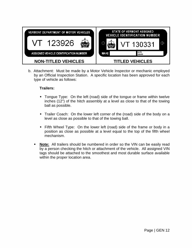
NON-TITLED VEHICLES TITLED VEHICLES
b. Attachment: Must be made by a Motor Vehicle Inspector or mechanic employed
by an Official Inspection Station. A specific location has been approved for each type of vehicle as follows:
Trailers: Tongue Type: On the left (road) side of the tongue or frame within twelve
inches (12”) of the hitch assembly at a level as close to that of the towing ball as possible.
Trailer Coach: On the lower left corner of the (road) side of the body on a
level as close as possible to that of the towing ball. Fifth Wheel Type: On the lower left (road) side of the frame or body in a
position as close as possible at a level equal to the top of the fifth wheel mechanism.
Note: All trailers should be numbered in order so the VIN can be easily read
by a person checking the hitch or attachment of the vehicle. All assigned VIN tags should be attached to the smoothest and most durable surface available within the proper location area.
Page | GEN 12

ASSIGNED VEHICLE IDENTIFICATION NUMBER LOCATIONS
ATTACH VERMONT ASSIGNED VIN’S IN THE AREAS MARKED BY THE
ARROW AND BOX.
Boat Trailer
Lowboy Trailer
Utility Trailer
Page | GEN 13
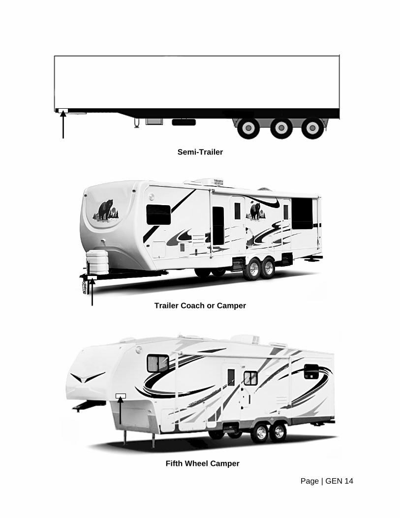
Semi-Trailer
Trailer Coach or Camper
Fifth Wheel Camper
Page | GEN 14

Rebuilt, Reconstructed or Homemade Vehicles (Cars and Trucks):
The VIN plate will be attached to the left front door pillar post high enough
so it may be easily read when opening the door. The assigned VIN tag must be located in a position where it can be easily
read from the operator's side of the vehicle. The type and rigidity of the material should be considered. All tags should be on an outside surface which is smooth and clean. The tag should be right side up, if possible, and away from any place where it will experience any kind of wear.
LOST PLATE Whenever a registration plate has been lost, damaged, worn or faded to the extent that it is not plainly legible, the vehicle cannot be inspected until the following is completed:
1. Collect fee for duplicate plate. 2. Submit fee and request for replacement plate to the Department of Motor Vehicles. Note: A trailer cannot be inspected without a plate.
Page | GEN 15

REPLACEMENT FORMS
1. The duplicate registration form (TA-VL-15) can be obtained from the Department of
Motor Vehicles via the submission of a Stockroom Order Form. Order forms can be obtained by calling (802) 828-2090.
2. Lost registration plate forms (TA-VD-16) can be obtained from the Department of
Motor Vehicles via the submission of a Stockroom Order Form. Order forms can be obtained by calling (802) 828-2090.
AUTOMATED VEHICLE INSPECTION PROGRAM
After a date to be established by the Commissioner, all inspections shall be conducted online to the Automated Vehicle Inspection Program (AVIP) database. No offline inspections will be permitted except as expressly authorized by the Commissioner. Inspection Stations shall acquire their workstations from the designated vendor or as determined by the Commissioner. An Inspection Station’s workstation computer shall transmit the inspection data required by the Commissioner to the AVIP database.
MANDATORY INSURANCE Vermont is a mandatory insurance state. Refer to Section 1 ~ Registration and Insurance.
Page | GEN 16


SCHEDULE OF PENALTIES AND SUSPENSION
VIOLATIONS OF STATE INSPECTION REGULATIONS
DEFINITIONS
For the purposes of this Section, words and terms shall have the following meanings, unless the context clearly indicates otherwise: Certificate of Inspection: The nontransferable inspection sticker (and
accompanying number of expiration month) which is issued by an Inspection Mechanic to a vehicle to certify the vehicle to which it is attached has successfully passed all the state's inspection requirements. All losses of certificates of inspection must be reported to the Department immediately. If for any reason a certificate of inspection (sticker) is voided it must be attached to the corresponding log sheet for the inspection book and returned to the Department along with the rest of the log sheet when the book is used or otherwise returned.
Department: The Department of Motor Vehicles. Hearing: If an inspection station owner/operator, and/or Certified Inspection
Mechanic wishes to contest a warning, administrative penalty or order of suspension, he/she shall have a right to a hearing before a hearings examiner of the Transportation Policy and Hearing Section provided the inspection station owner or operator or Certified Inspection Mechanic submits a request for such hearing within fifteen (15) days of the notice, in writing, to the Agency of Transportation, Transportation Policy and Hearing Section, National Life Building, Drawer 33, Montpelier, VT 05633-5001. When a hearing is requested the warning, suspension or the administrative penalty shall be held in abeyance until the decision of the hearing, unless the Commissioner has cause to believe the inspection station or Certified Inspection Mechanic will continue to act in such a manner as to be detrimental to the state or any existing or potential customers, in which case the warning, suspension or administrative penalty shall become effective as indicated in the original order.
Inspection Area: The specifically approved area of an inspection station inside a building in which all vehicle inspections must be conducted, unless prior approval has been obtained from the Department of Motor Vehicles. Trailers may be inspected outside the building. The road test must be conducted outside. The Inspection Area is also the only location at which the certificate of inspection shall be issued and affixed to the vehicle.
Page | S/P 1
Inspection Books: The books containing the certificates of inspection and accompanying log sheet. These books must immediately be returned to the Department when completely used or before the last day of February following the issue of new stickers, unless a fleet or replacement station or when expired or when the station is no longer in business or certified to inspect vehicles.
Inspection Fee: If a fee is charged, it must be approved by the Commissioner and
shall be determined by the time actually spent to complete the inspection multiplied by the posted hourly rate or be a posted flat rate fee based upon the average time to conduct a complete inspection. Costs of parts and time for repairs shall be recorded separately.
Certified Inspection Mechanic: Any individual who is at least 18 years of age and
has successfully completed the Certified Inspection Mechanic exam is qualified and capable of conducting safety inspections of the various kinds of vehicles and who actually conducts the state inspection of the vehicle for which he/she is qualified. The mechanic signing the inspection log sheet shall have conducted the inspection of the vehicle and be responsible for the road test. If the road test is performed by someone other than the inspecting mechanic, that person must hold a valid operator license in the proper class and/or endorsement for the vehicle being inspected and must sign the inspection log along with the inspecting mechanic. Periodic inspections may be performed only by mechanics that have been certified by the Commissioner. An uncertified person employed as an Inspection Mechanic may perform inspections during the first thirty (30) days that he or she is employed by the inspection station, under the direct supervision of the station supervisor, or a certified mechanic.
Individuals age 16 or 17 that have completed an approved vocational school
Inspection Mechanic credentialing program may be issued a “provisional” inspection license. Upon being issued a provisional inspection license, these individuals may perform vehicle inspections, except for the vehicle road test (a fully Certified Inspection Mechanic must perform this test). Additionally, their inspection must be approved and signed off by a fully Certified Inspection Mechanic, vouching for their work. The provisional inspection license may be surrendered any time on or after the licensee’s 18th birthday in favor of a full certification.
Inspection Period: Shall mean the two (2) month period within which a Certificate
of Inspection may be issued. Example: Only a number "2" may be affixed during the period between January 1st and the last day of February; a number "4" between March 1st and April 30th; and so on for each of the six (6) periods.
Inspection Record: The legible information log sheet attached to and including the
certificate of inspection. The log sheet, sticker and OBD II form if applicable must be completely and accurately filled out at inspection time.
Page | S/P 2

Inspection Station License: The certificate of designation issued by the Department to verify the facility is properly equipped and has adequate space and qualified personnel to conduct state inspection of vehicles as stated on the certificate. The license must be conspicuously displayed at the place for which it has been issued. It shall be valid only for the Official Inspection Station in whose name it has been issued and for transacting business only at the designated place.
Inspection Station Supervisor: Any person designated by the inspection station
owner to supervise/manage the operation of the respective inspection station. Official Inspection Station: A government agency owned or leased, or privately
owned or leased facility designated and licensed by the Department to conduct state inspections of vehicles as stated on the license certificate.
Periodic Inspection Manual: Those books, pamphlets or bulletins distributed by
the Department containing the rules that govern the action of Official Inspection Stations and Certified Inspection Mechanics to determine whether the motor vehicles are properly equipped and maintained in good mechanical condition.
Person: A natural person, firm, co-partnership, association or corporation that
owns the business to which the inspection station license has been issued. Proof of Insurance: Shall be one of the following: An insurance identification card.
The declaration page from the policy or a photocopy of that page.
A temporary card or binder, or a photocopy of a binder.
A self-insurance card.
Evidence of a bond issued by a surety company.
Registration: The authority for a vehicle to be operated on a public highway as evidenced by the issuance of an identifying certificate and plate or plates issued by a governmental entity. A temporary registration plate does qualify as a registration.
SAE: The Society of Automotive Engineers International (SAE) is a professional
organization for engineering professionals in aerospace, automotive and the commercial vehicle industries. The Society is a standards development organization for the engineering of powered vehicles of all kinds, including cars, trucks, boats, aircraft and others.
State Inspection Requirements: All the rules as described in the Periodic
Inspection Manual distributed by the Department, used for the purpose of
Page | S/P 3

determining whether the motor vehicles are properly equipped and maintained in good mechanical condition.
Secure Location: Shall mean a lockable desk, file cabinet, strongbox, safe or other
non-portable similar device where all Certificates of Inspection shall be kept safe and secure when in the possession of an Official Inspection Station.
Suspend: To withdraw temporarily by formal action of the Department any license,
certification, registration or privilege issued or granted by the Department. On the effective date, an inspector shall pick up the following applicable items: any inspection stickers, logs and official inspection certificate from the station or mechanic whose designation has been suspended.
Revoke: To withdraw permanently by formal action of the Department any license,
certification, registration or privilege issued or granted by the Department. On the effective date, an inspector shall pick up the following applicable items; any inspection stickers, logs and official inspection certificate from the station or mechanic whose designation has been revoked.
VIN – Vehicle Identification Number: A combination of numerals or letters or both
which the manufacturer assigns to a vehicle for identification purposes or, in the absence of a manufacturer-assigned number, which the Department assigns to a vehicle for identification purposes.
Serious Violation:
(1) Three or more violations of Category 1, Category 2, Category 3 or Category 4, or any combination thereof, occurring during the same inspection of a single vehicle;
(2) Three or more violations of Category 1, Category 2, Category 3 or Category 4,
or any combination thereof, occurring during the inspections conducted by a fleet inspection station during the same inspection period.
CAUSE FOR ADMINISTRATIVE PENALTY AND SUSPENSION
Schedule: The complete operation of an inspection station shall be the
responsibility of the owner. Failure to comply with the provisions of this Section will be considered sufficient cause for suspension of any or all Inspection Mechanic or inspection station certificates. Administrative penalties or suspensions may be imposed upon the inspection station or Inspection Mechanic, or both, that had primary responsibility for the violation. All requests for penalties or suspensions will be reviewed and approved by the Commissioner prior to being effectuated. An inspection station owner/operator or Certified Inspection Mechanic to whom an administrative penalty or suspension has been issued will be afforded the
Page | S/P 4
opportunity for a hearing. In addition thereto, violators may be subject to criminal or civil prosecution.
Inspection Station: After the full term of suspension has been served,
inspection privileges will not be restored until an application for reappointment has been reviewed and the station has been approved by the Department.
Certified Inspection Mechanic: After the full term of suspension has been
served, the Inspection Mechanic certificate shall be restored. Warning: The Department, or authorized agent of the Commissioner of Motor
Vehicles in its discretion, may issue written warnings to the inspection station or Certified Inspection Mechanic for any violation in Category 2 through 5 inclusive. In either case, written documentation and a written acknowledgment of receipt of the warning must be submitted to the Department by the authorized agent of the Commissioner of Motor Vehicles. The warning receipt acknowledgment must be signed by the station owner, Certified Inspection Mechanic, operator or supervisor.
Subsequent: Determination of second and subsequent violations is made on the
basis of previous violations in the same category. Multiple Violations: In the case of multiple violations considered at one time, the
Department will impose separate penalties for each violation as required by schedule, however, in the case of multiple violations considered at one time, the Department may, in its discretion, direct that any suspensions be served concurrently.
Sale of Business: If an inspection station that is currently suspended is sold or
leased to a new owner, an application will be considered provided the suspended parties have no interest whatsoever in the new inspection station.
Failure to Pay the Administrative Penalty: In the case of failure to pay an
administrative penalty, the Department of Motor Vehicles shall mail a notice to the Inspection Station or Inspection Mechanic at their last known address notifying the inspection station and/or Inspection Mechanic failure to pay or otherwise satisfy the administrative penalty within sixty (60) days of the notice will result in suspension of the inspection certificate of the station and/or the mechanic, whichever is appropriate, until the penalty is paid in full or otherwise satisfied. The inspection station or Inspection Mechanic shall be entitled to a hearing if requested within fifteen (15) days.
Serious Violation: The Commissioner may suspend, the certificate of the
inspection station or the Inspection Mechanic or both, whichever is deemed appropriate by the Commissioner, in addition to the administrative penalty or penalties set forth in Categories 1 through Category 5, when a serious violation has occurred. Additionally, the Commissioner may revoke the inspection certification
Page | S/P 5

from a mechanic who has been found to be stealing or fraudulently gaining stickers for his/her own use or illegal sale.
Page | S/P 6
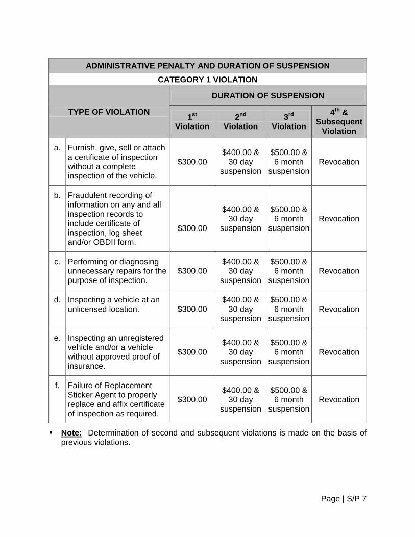
ADMINISTRATIVE PENALTY AND DURATION OF SUSPENSION
CATEGORY 1 VIOLATION
TYPE OF VIOLATION
DURATION OF SUSPENSION
1st Violation
2nd Violation
3rd Violation
4th & Subsequent
Violation
a. Furnish, give, sell or attach a certificate of inspection without a complete inspection of the vehicle.
$300.00 $400.00 &
30 day suspension
$500.00 & 6 month
suspension Revocation
b.
Fraudulent recording of information on any and all inspection records to include certificate of inspection, log sheet and/or OBDII form.
$300.00
$400.00 & 30 day
suspension
$500.00 & 6 month
suspension Revocation
c. Performing or diagnosing unnecessary repairs for the purpose of inspection.
$300.00 $400.00 &
30 day suspension
$500.00 & 6 month
suspension Revocation
d. Inspecting a vehicle at an unlicensed location. $300.00
$400.00 & 30 day
suspension
$500.00 & 6 month
suspension Revocation
e. Inspecting an unregistered vehicle and/or a vehicle without approved proof of insurance.
$300.00 $400.00 &
30 day suspension
$500.00 & 6 month
suspension Revocation
f. Failure of Replacement Sticker Agent to properly replace and affix certificate of inspection as required.
$300.00 $400.00 &
30 day suspension
$500.00 & 6 month
suspension Revocation
Note: Determination of second and subsequent violations is made on the basis of previous violations.
Page | S/P 7

ADMINISTRATIVE PENALTY AND DURATION OF SUSPENSION
CATEGORY 2 VIOLATION
TYPE OF VIOLATION
DURATION OF SUSPENSION
1st Violation
2nd Violation
3rd Violation
4th & Subsequent
Violation
a. Inspection of a vehicle not owned by and registered to the fleet inspection station.
$120.00 $220.00 $300.00 &
30 day suspension
1 year suspension
b. Inspection by uncertified, unauthorized or suspended mechanic.
$120.00 $220.00 $300.00 &
30 day suspension
1 year suspension
c. Inspecting a vehicle with missing registration certificate or registration plate or validation sticker(s) or unreadable registration plate.
$120.00 $220.00 $300.00 &
30 day suspension
1 year suspension
d. Failure to verify VIN and registration information with vehicle or inspection of a vehicle with unreadable or missing VIN plate.
$120.00 $220.00 $300.00 &
30 day suspension
1 year suspension
e. Faulty or incomplete inspection, inspecting a vehicle with inoperable, illegal or defective equipment.
$120.00 $220.00 $300.00 &
30 day suspension
1 year suspension
f. Inspection of a vehicle in a facility without the required tools, equipment, space or any of the requirements of the provisions for designation.
$120.00 $220.00 $300.00 &
30 day suspension
1 year suspension
g. Inspection of a vehicle of which the vehicle was taken on a road test by a mechanic with a suspended operator’s license.
$120.00 $220.00 $300.00 &
30 day suspension
1 year suspension
Page | S/P 8

ADMINISTRATIVE PENALTY AND DURATION OF SUSPENSION CATEGORY 2 VIOLATION
TYPE OF VIOLATION
DURATION OF SUSPENSION
1st Violation
2nd Violation
3rd Violation
4th & Subsequent
Violation
h. Failure to return all Department materials to the Department immediately upon revocation, suspension, cancellation or discontinuance of business.
$120.00 $220.00 $300.00 &
30 day suspension
1 year suspension
i. Failure to comply with any of the provisions for inspection station designation.
$120.00 $220.00 $300.00 &
30 day suspension
1 year suspension
Note: Determination of second and subsequent violations is made on the basis of previous violations.
Page | S/P 9

ADMINISTRATIVE PENALTY AND DURATION OF SUSPENSION CATEGORY 3 VIOLATION
TYPE OF VIOLATION
DURATION OF SUSPENSION
1st Violation
2nd Violation
3rd Violation
4th & Subsequent
Violation a. Failure to produce inspection
records or related work orders to the Department, or agent on request.
$65.00 $120.00 $200.00 &
30 day suspension
6 month suspension
b. Failure to maintain inspection log, or improper, inaccurate or incomplete recording of information on inspection records.
$65.00 $120.00 $200.00 &
30 day suspension
6 month suspension
c. Failure to assign correct expiration/date month on certificate of inspection.
$65.00 $120.00 $200.00 &
30 day suspension
6 month suspension
d. Failure to conspicuously display inspection station license, hourly rate or flat fee rate.
$65.00 $120.00 $200.00 &
30 day suspension
6 month suspension
e. Failure to notify the Department immediately in writing of changes of ownership, name or location affecting an Official Inspection Station.
$65.00 $120.00 $200.00 &
30 day suspension
6 month suspension
f. Failure to report within two (2) business days of the loss or theft of certificate of inspection to the Department.
$65.00 $120.00 $200.00 &
30 day suspension
6 month suspension
g. Failure to immediately notify the Department of Motor Vehicles upon temporary or permanent closing of the inspection station or a change of business hours.
$65.00 $120.00 $200.00 &
30 day suspension
6 month suspension
Note: Determination of second and subsequent violations is made on the basis of previous violations.
Page | S/P 10

ADMINISTRATIVE PENALTY AND DURATION OF SUSPENSION
CATEGORY 4 VIOLATION
TYPE OF VIOLATION
DURATION OF SUSPENSION
1st Violation
2nd Violation
3rd Violation
4th & Subsequent
Violation a. Failure to affix certificate of
inspection to correct vehicle. $25.00 $30.00 $65.00 3 month suspension
b. Loaning certificates of inspection to or borrowing certificates of inspection from another inspection station.
$25.00 $30.00 $65.00 3 month suspension
c. Failure to return unused inspection stickers before the end of February following the use of the next year’s stickers.
$25.00 $30.00 $65.00 3 month suspension
Note: Determination of second and subsequent violations is made on the basis of previous violations.
Page | S/P 11

ADMINISTRATIVE PENALTY AND DURATION OF SUSPENSION
CATEGORY 5 VIOLATION
TYPE OF VIOLATION
DURATION OF SUSPENSION
1st Violation
2nd Violation
3rd Violation
4th & Subsequent
Violation a. Illegible recording of
information on any and all inspection records to include certificate of inspection, log sheet and/or OBDII form.
Warning $10.00 $25.00 30 day suspension
b. Failure of 2nd mechanic to sign log sheet when primary Inspection Mechanic’s operator’s license is under suspension or does not hold a valid class or endorsement on driver’s license; or holds a provisional inspection license.
Warning $10.00 $25.00 30 day suspension
c. Failure to maintain and/or update station’s Vermont Periodic Inspection Manual.
Warning $10.00 $25.00 30 day suspension
Note: Determination of second and subsequent violations is made on the basis of previous violations.
Page | S/P 12


TABLE OF CONTENTS
PLEASURE CAR AND LIGHT TRUCK SECTION
SUBJECT PAGE NUMBER
Section 1 ~ Registration and Insurance CAR 1.1 – CAR 1.2
Section 2 ~ Wheels and Tires CAR 2.1 – CAR 2.4
Section 3 ~ Steering and Suspension CAR 3.1 – CAR 3.6
Section 4 ~ Brake Systems CAR 4.1 – CAR 4.6
Section 5 ~ Lighting and Electrical System CAR 5.1 – CAR 5.11
Section 6 ~ Vehicle Glazing (Glass) CAR 6.1 – CAR 6.7
Section 7 ~ Body and Sheet Metal CAR 7.1 – CAR 7.10
Section 8 ~ Exhaust System CAR 8.1 – CAR 8.2
Section 9 ~ Fuel System CAR 9.1 – CAR 9.2
Section 10 ~ Reconstructed and/or Special Motor Vehicles CAR 10.1 – CAR 10.13
Section 11 ~ Emission Controls CAR 11.1 – CAR 11.6
Section 12 ~ Flaps and Fenders CAR 12.1 – CAR 12.2


SECTION 1 – REGISTRATION AND INSURANCE
The first step in the inspection of a vehicle should be a short review of the registration, plates and insurance certificate. Agreement Among Papers: Procedure:
Inspect registration certificate, license plates, vehicle description and vehicle identification number or numbers. Compare to determine if there is proper agreement among them.
Reject vehicle if: 1. Vehicle description or identification number is not in agreement with registration
certificate. 2. Numbers on license plates are not in agreement with numbers on registration
certificate. 3. Registration certificate is lost or missing.
Note: Vehicle registrations obtained via the Vermont DMV website are valid for a period of 10 days from the date of issue and serve as temporary registrations. These are permissible for inspection purposes.
4. If VIN tag on vehicle’s dash area has been removed, tampered with or not visible.
Note: If the VIN has been removed or tampered with, contact your local Police Department to report it.
Plate Mounting and Condition: Procedure:
1. Inspect license plates to see they are securely mounted and are clean and clearly visible.
2. Ensure license plates are mounted horizontally.
3. Rear plate must be mounted in required position in order to be illuminated by rear
plate light.
4. Ensure plates are clearly visible.
Page | CAR 1.1
5. Ensure rear validation sticker is unobstructed and affixed in the lower right corner
of the license plate. Reject vehicle if:
1. License plates are hanging loosely from their mounting bracket or if the plate or plates are missing. (Refer to the preceding page for detailed instructions.)
2. Either the front or rear plate is missing, covered in a way that inhibits clearly viewing the numbers and letters, has been lost, damaged, worn or faded to the extent that it is not plainly legible, or otherwise not visible.
Insurance Certificate: Procedure:
Inspect for proof of insurance and ensure that the card properly describes the vehicle and owner. Examine the effective and expiration dates to determine if the policy is valid.
Reject vehicle if:
1. No insurance identification card, or
2. No declaration page from the policy or a photocopy of that page, or 3. No temporary card or binder, or a photocopy of a binder, or 4. No self-insurance card, or
5. No evidence of a bond by a surety company.
6. Information on card does not match vehicle and/or owner.
7. Insurance card is not in effect or has expired.
Page | CAR 1.2


SECTION 2 – WHEELS AND TIRES
Reference is made to the figures below for visual aid in determining tire wear. This inspection is visual. Equipment: Tread depth-measuring gauge. Procedure: 1. Inspect for tire wear. a. Tires without tread wear indicators. Reject vehicle if:
Tire is worn so that less than 2/32” tread remains in any two (2) adjacent major grooves at three (3) locations spaced equally around outside of tire. (Figure 1)
b. Tires with tread wear indicators. Reject vehicle if:
Tire is worn so that the tread wear indicators contact the road in any two (2) adjacent major grooves at three (3) locations spaced equally around outside of tire. (Figure 2)
Figure 1 – Tire Tread Depth
2/32” = 1.6 MM
Page | CAR 2.1

Figure 2 – Tire Wear
Any tire worn to the level of the tread wear indicators in any two (2) or more adjacent tread grooves or when cord or fabric is exposed.
Any tire worn to the point where less than 2/32” of an inch of tread design depth remains in any two (2) or more adjacent major tread groves, exclusive of tie bars, or when cord or fabric is exposed.
2. Inspect for cord exposure. Reject vehicle if: Tire has a worn spot that exposes the cord through the tread (Figure 3).
Figure 3 – Tire Construction
Bias-Ply Radial-Ply Bias-Belted 3. Inspect for tread cuts, snags or sidewall cracks. Reject vehicle if:
Tire has tread cuts, snags or sidewall cracks.
Page | CAR 2.2
4. Inspect for bumps, bulges or knots. Reject vehicle if:
Tire has visible bumps, bulges or knots indicating partial failure or separation of the tire structure.
5. Inspect for regrooved or recut tires. Reject vehicle if:
Tire has been regrooved or recut below original groove depth, except special tires that have undertread rubber for this purpose and can be identified as such by markings on the tire.
6. Inspect wheel bolts, nuts or lugs. Reject vehicle if: Wheel bolts, nuts, studs or lugs are loose, missing or damaged. 7. Inspect for wheel damage. Reject vehicle if:
Any part of wheel is bent, cracked, rewelded, damaged or has elongated boltholes so as to affect safe operation of the vehicle.
8. Inspect for equal tire size. Reject vehicle if: Tires on the same axle are not the same type construction or size. Note: As a general rule, do not mix different size tires on the same axle.
However, it may be permissible to mount tires having different size descriptions (U.S. standard metric) on the same axle when construction, dimensions and load capacity are compatible. Consult the manufacturer for specific permissible practice.
9. Inspect for restricted usage markings on tires. Reject vehicle if:
Tire is marked "FOR FARM USE ONLY", "OFF HIGHWAY USE ONLY" or "FOR RACING USE ONLY", etc.
Page | CAR 2.3

10. Inspect for low-pressure air warning light/indicator being on. Reject vehicle if: Low-pressure air warning light/indicator is activated.
Page | CAR 2.4


SECTION 3 – STEERING AND SUSPENSION
WHEEL BEARINGS
Lifting techniques and wheel bearing movement vary. Consult manufacturer’s specifications for proper lifting techniques and bearing movement. Equipment: Floor jack or lift, rule or gauge Procedure: With vehicle lifted properly, grasp tire at top and bottom, rock in and out and record movement. Caution: If air suspension vehicles are lifted via body support area, air spring
damage may occur if the air suspension switch is not turned off. Reject vehicle if: If relative movement is more than manufacturer’s specifications.
Page | CAR 3.1

STEERING LINKAGE LASH/TRAVEL
Lifting techniques vary for measuring steering linkage play. Refer to manufacturer’s specifications for proper lifting and testing procedures. (Refer to diagram on previous page if necessary.) 1. Steering linkage play: Procedure: Test vehicle per manufacturer’s specification. Reject vehicle if:
Measured movement exceeds manufacturer’s specifications. 2. Lash or free play: Equipment: Ruler, scale or lash-checking instrument. Procedure:
Measure per manufacturer’s specifications. Reject vehicle: If lash or freeplay exceeds manufacturer’s specifications. 3. Power steering: Procedure: a. Check fluid level and belt tension on power steering pump.
b. Bring fluid to proper level and make certain that belts are properly tensioned before proceeding.
Page | CAR 3.2

4. Steering system travel: Procedure:
Turn steering wheel through a full right and left turn. (On vehicles without power steering, it may be desirable to unload front wheels slightly by raising wheels off the surface.)
Reject vehicle if:
Front wheels are incapable of being turned to the right and left steering stops without binding or interference.
Note: Some light trucks and older pleasure cars are equipped with kingpins.
Refer to Section 3 of the Heavy Truck and Bus Section for tolerances.
STEERING AND SUSPENSION 1. Check all electric and/or hydraulic power steering system components for proper
function.
Reject vehicle if: Any electric and/or hydraulic power steering system component fails to function as designed.
2. Check power steering system for excessive fluid leaks.
Reject vehicle if: Any power steering system component exhibits excessive fluid leak.
3. Check power steering belt for dry rot and/or cracks. Reject vehicle if: Power steering belt exhibits dry rot and/or cracks.
TORSION BARS, SPRINGS, SHOCK ABSORBERS/STRUTS
1. Visually inspect springs and torsion bars. Equipment: Lift or hydraulic jack, safety stand and trouble light.
Page | CAR 3.3
Procedure:
a. With unloaded vehicle on a level surface, visually inspect the heights of the four corners of the vehicle. If necessary, use measuring device and determine differences from side to side.
b. Visually inspect for broken leaf springs, coil springs, air springs or torsion bar
damage. Inspect spring shackles, bushings and "U" bolts. Caution: If air suspension vehicles are lifted via body support area, air spring
damage may occur if the air suspension switch is not turned off. Reject vehicle if:
a. Vehicle height is not within the manufacturer's recommended specifications. b. Spring or torsion bars are broken. c. Shackles or "U" bolts worn or loose. d. Air springs are collapsed.
2. Inspect shock absorbers/shock struts. Equipment: Lift or hydraulic jack and safety stand. Procedure:
a. With vehicle on a level surface, push down on all four corners of vehicle and release.
b. With vehicle on a lift or jacked up, visually inspect shock absorbers for excessive
leakage, looseness or mounting brackets and bolts. Reject vehicle if:
a. Vehicle continues free rocking motion after release, indicating loss of shock absorber function.
b. Severe leakage (not slight dampness) is evident. c. Mounting bolts or mounts are loose or broken.
Page | CAR 3.4

BALL JOINT WEAR
Procedure: Inspect ball joint(s) per manufacturer’s instructions. Reject vehicle if: Ball joint wear exceeds manufacturer’s specifications.
HYME JOINTS – CONTROL ARM ASSEMBLIES The design of some upper and/or lower control arm assemblies consists of an inner steel sleeve mounted in a rubber bushing on one end of an adjustable or non-adjustable shaft and a ball joint on the other end of the shaft. The bushing style end of the control arm is sometimes referred to as a “Hyme Joint”.
Equipment:
Floor jack or lift, rule or gauge. Procedure: 1. With vehicle lifted properly grasp tire at top and bottom,
rock in and out and record movement. There should be no movement or play in the Hyme Joint part of the control arm assembly.
2. Consult manufacturer accepted tolerance for ball joint wear. Caution: If air suspension vehicles are lifted via body support area, air spring
damage may occur if the air suspension switch is not turned off. Reject vehicle if: 1. There is any play in the Hyme Joint, or the ball joint wear exceeds manufacturer
limits. 2. Control arm is severely rusted to a point where its integrity is compromised. Illustrated is a typical control arm assembly, made up of a ball joint and Hyme Joint connected by an adjustable shaft. Check for deterioration of the rubber which bonds the inner bushing to the control arm on the Hyme Joint. If there is zero play in the joint but the rubber bushing is severely deteriorated consider changing the assembly.
Page | CAR 3.5
CV JOINT / U-JOINTS
Equipment:
Floor jack or lift. Procedure: Check for excessive play in knuckles or U-joints. Note: Potential problems with CV joints and U-joints can be detected during vehicle
test drive. Reject vehicle if: CV joints or U-joints are loose enough to cause a dangerous driving condition.
Page | CAR 3.6


SECTION 4 – BRAKE SYSTEMS
It is required the vehicle be road tested either on the highway or in the station yard provided there is sufficient space to conduct the road test safely. If during the road test the inspector detects or suspects a problem with one (1) or more of the brakes, all four wheels must be removed and inspected per the requirements described in “Brake Lining Thickness” located further on in this section. Note: With prior approval from the Department, automated brake testing equipment
can be used in lieu of a road test.
ROAD TEST – SERVICE BRAKE PERFORMANCE REQUIREMENTS Procedure: 1. At a speed of 20 MPH, apply service brake firmly without lockup. 2. Observe whether vehicle comes to a smooth stop within the distance prescribed by
state law (twenty-five feet [25’]) without pulling to the right or left.
3. Driver should have firm control of the steering wheel throughout the test. Reject vehicle if: 1. The vehicle requires more than twenty-five feet (25’) in which to stop from 20 MPH.
2. The vehicle swerves enough for any wheel to leave the twelve-foot (12’) lane.
FAILURE INDICATOR LAMP/BRAKE WARNING LIGHT The failure indicator lamp is required on all passenger cars manufactured after January 1, 1968 and all other vehicles after January 1, 1975. Procedure: 1. Apply parking/hand brake and turn ignition to "ON" position or verify lamp operation
by other means indicated by vehicle manufacturer.
2. Start the engine. The warning light should illuminate in the "ON" or "START" position.
Page | CAR 4.1

3. Release the parking/hand brake. The warning light should turn itself off unless it is an anti-lock brake system and the hydraulic pump has not reached its minimum pressure.
Reject vehicle if: 1. The brake system failure indicator light or warning light does not illuminate.
2. The brake system failure indicator light or warning light remains illuminated after the
engine is started and the parking/hand brake released.
3. The brake and/or anti-lock warning light remains on longer than sixty (60) seconds.
BRAKE SYSTEM INTEGRITY/PEDAL RESERVE The brake system shall demonstrate integrity as indicated by no noticeable/visible decrease in pedal height under one hundred and fifty (150) pound force applied to the brake pedal or by no illumination of the brake system failure indicator lamp. The brake system must withstand the application of force to the pedal without failure of any line or other part. Equipment: Use a pedal pressure gauge or inspector judgment for measuring the one hundred and fifty (150) pound force. Procedure: While the vehicle is stopped and the engine running on vehicles with power brakes, apply one hundred and fifty (150) pounds (68 kgs.) pressure to the brake pedal. Reject vehicle if: Brake warning light illuminates or the brake pedal falls away under pressure or contacts some object that prohibits brake pedal travel.
Page | CAR 4.2

Note: Visual check of brake hoses, assemblies and master cylinder. Always
inspect a brake assembly that shows evidence of throwing fluid or grease.
HYDRAULIC PARTS/BRAKE HOSES AND ASSEMBLIES Procedure: Visually inspect hoses, tubing and connections, inspecting front brake hoses through all wheel positions from full left to full right for conditions indicated. Protective devices, such as "rub rings", shall not be considered part of the hose or tubing. Reject vehicle if: 1. Wheel cylinders leak. 2. Hoses or tubing leak or are cracked, chafed, flattened, restricted, insecurely
fastened, improperly retained or rusted. 3. If repairs have been made with copper tubing or compression fittings.
MASTER CYLINDER Procedure: 1. Inspect for leaking and fluid level. 2. Thoroughly clean the area, remove cover and check fluid level. (Be sure no dirt gets
into reservoir when cover is removed and that the gasket is serviceable.) Reject vehicle if: 1. Master cylinder leaks.
Page | CAR 4.3

2. The fluid level is more than one-half of an inch (½”) below the lowest edge of the
filler opening in either reservoir chamber or is below the minimum level indicated by manufacturer on the reservoir.
3. The gasket is torn, damaged or swollen (swollen gasket may indicate oil in system). Note: Low fluid in master cylinder reservoir chambers may be due to normal wear
of the front or rear linings. Brake Fluid Requirements: The law states after January 1, 1967, no person may distribute or provide any fluid for use in the hydraulic brake system of a motor vehicle unless it meets the Society of Automotive Engineers Standards of 70 R1 or better, and any container must bear a statement of its classification such as SAE 70 R1 or SAE 70 R3.
BRAKE ROTORS Procedure: 1. Check rotor(s) for warping and excessive rust and corrosion.
2. Check thickness of rotor(s) with rotor thickness caliper. Reject vehicle if: 1. Rotor(s) thickness is less than manufacturer’s listed minimum tolerance. 2. Cooling vanes on vented rotors are corroded or rusted to the point where the rotor
collapses when pressure is applied by the brake caliper.
Page | CAR 4.4

3. Rust exists on contact surface of rotor or drum. 4. Evidence of cracks exist on rotor or drum.
BRAKE DRUMS Procedure: Check drum(s) inside diameter with proper measuring tool. Reject vehicle if: 1. Drum inside diameter exceeds manufacturer’s listed maximum tolerance.
2. Rust and/or cracks exist on drum contact surface.
PARKING/HAND BRAKE OPERATIONS Note: Prior to road testing the vehicle, the parking/hand brake should be inspected
for reserve travel. The parking/hand brake system is a brake system used to hold and maintain a vehicle in a stationary position when the vehicle is unattended. Procedure: 1. Inspect parking/hand brake function for setting and release.
2. With vehicle transmission in neutral, set the parking/hand brake firmly to determine
the reserve travel of the hand lever or foot pedal. Reject vehicle if: 1. There is no reserve travel in the lever or pedal.
2. If the parking/hand brake will not hold the vehicle stationary with the engine running
at slightly accelerated speed with shift lever in drive position for automatic transmission or shift lever in low gear with clutch engaged for standard shift transmission.
Page | CAR 4.5

CONDITION OF MECHANICAL COMPONENTS
Procedure: Inspect for worn pins, missing or defective cotter pins, broken or missing springs, worn or frozen cables, clevises, couplings, rods and anchor pins. Reject vehicle if: Mechanical parts are missing, frozen, broken or badly worn. Note: Service brake tests should be conducted on a substantially dry, hard, smooth
surface road or area free from loose material, oil or grease.
BRAKE LINING THICKNESS REQUIREMENTS Note: This does not apply to heavy trucks per the Heavy Truck and Bus section of
this manual. Procedure: The Inspection Mechanic must remove at least one wheel from the vehicle and inspect brake lining for cracks, chips and thickness. Note: Removing a wheel is not required when conducting a first-time inspection on
a new car, unless a problem is detected during the vehicle road test. Reject vehicle if: 1. Brake lining does not meet manufacturer’s minimum thickness recommendations.
2. If brake lining shows evidence of cracks, chips or if adhesion to backing plate is
compromised.
Page | CAR 4.6


SECTION 5 – LIGHTING AND ELECTRICAL SYSTEMS
General lamp and reflector inspection. This includes all original equipment, exterior lighting plus whatever lights have been added. If a vehicle is equipped with a light, it must work properly. Visual Check of Lamp Function: If only one inspector is checking, large mirrors may be placed so that all lamps may be observed from driver's position. Procedure: Turn on the night driving lights and visually check the following (check 1 and 2 with ignition switch on): 1. Actuate turn signal level to right and left and observe function of turn signal lights,
indicator lamps and front cornering lamps.
2. Place vehicle in reverse gear and check back-up lamps (if car is so equipped).
3. If car is so equipped, actuate the following and observe lamps. Brake warning lamps Indicator lamps
Hazard warning lamps Stop lamps, including high center mount stop lamp Headlamps – upper and lower beam
4. Observe function of all other lamps: Clearance lamps Reflex reflectors Emergency warning lamps Side marker lamps Identification lamps Tail lamps Parking lamps All others
5. All lamps and reflectors should be approved and marked with the proper code letter.
Although it is impractical to inspect all items for these markings, this method can be used for rejection if a lamp is not functioning properly or is not properly marked.
Reject vehicle if: 1. Any required lamp is missing.
2. Any bulb or sealed beam unit fails to light.
3. Turn signals do not properly indicate right and left when so switched.
Page | CAR 5.1

4. Back-up light system does not turn off automatically when the vehicle goes forward.
5. Lamp shows color contrary to law.
6. Lamp fails to light the proper filament indicated at switch position.
7. Any lamp or reflector does not direct light properly.
8. Auxiliary equipment (to include truck caps) is placed on, in or in front of any lamp
(except transparent covers which are part of original manufacturer's equipped headlamps and marked DOT Approved, i.e. after-market tinted lamp covers).
9. Lamp assembly improperly fastened.
10. Lamp has a cracked, broken or missing lens, or visible moisture on interior.
11. Any lamp fails to have the letters "DOT" horizontally or vertically on the lens.
12. Auxiliary or after-market "undercarriage" glow light(s) is placed on or under the
vehicle, whether flashing or steady burning.
13. Auxiliary or after-market "license plate" glow light(s) is placed on the vehicle, whether flashing or steady burning.
14. Any additional auxiliary or after market light(s), not designed to enhance safety and
have not been approved by the Commissioner, are placed on or in the vehicle, whether flashing or burning.
15. If vehicle is equipped with LED lamps, no more than fifty percent (50%) of any one
(1) lamp may be inoperable. NOTE: To save time, the inspector should develop a plan or sequence for
checking miscellaneous electrical items, many of which can be inspected while looking at other items.
ELECTRICAL SYSTEM COMPONENTS
HORN
Procedure: Horn should be securely fastened and work properly.
Page | CAR 5.2

Reject vehicle if: Horn is loose or fails to function.
ELECTRICAL SWITCHES Procedure: All switches should function properly. Reject vehicle if: Switches fail to function or turn signal switch fails to cancel, (if so designed).
ELECTRICAL WIRING Procedure: Check to make sure all wiring is well insulated and wires are not broken. Reject vehicle if: 1. Wiring insulation is worn.
2. Wire is broken.
3. Wire is rubbed bare.
4. Wire shows any evidence of burning or short-circuiting.
ELECTRICAL CONNECTIONS Procedure: All connectors should be tight and secure. Reject vehicle if: 1. Connector shows signs of excessive corrosion.
2. Connector terminals have backed out of plastic connector housing.
Page | CAR 5.3

3. Connectors used for trailer towing are not made through properly indexed and oriented matched connectors, or if permanent connection, wires are not properly spliced and insulated.
AUTOMATIC TRANSMISSION ONLY
Procedure: Check neutral safety starting system to determine starter operates only with gear selector in "P" and "N". Set parking/hand brake, place wheel blocks and with foot brake applied, turn on ignition switch. Reject vehicle if: Starter operates with gear selector in any gear other than "P" or "N".
HEADLAMP AIMING INFORMATION All equipment for testing headlamps must comply with the Society of Automotive Engineers Recommended Practice for Headlamps Inspection Equipment. When examining headlamps for illumination, if beams appear to be out of alignment, headlamp aim must be checked using one of the following methods. Photoelectric Testing Machine: Approved photoelectric testing machine that will
give essentially equivalent results. Headlamp Testing Machine: If a headlamp testing machine is used, it shall give
results equivalent to those obtained using the screen procedure shown below. It shall be in good repair and adjustment, and shall be used in accordance with the manufacturer's instructions. The machine using a photoelectric cell or cells to determine aim should also have a visual screen upon which the beam pattern is projected proportional to its appearance and aim on a screen at twenty-five feet (25’). Such visual screen shall be plainly visible to the operator and should have horizontal and vertical reference lines to permit visual appraisal of the lamp beam.
Headlamp Aiming by the Screen Method: Use per manufacturer’s instructions. Aiming Area Required: It is desirable to have a specific aiming area in a darkened
location. This should be sufficient for the vehicle and an additional twenty-five feet (25’) measured from face of lamps to the front of the visual screen.
The floor on which the car rests must be flat and level with the bottom of the screen. If the floor is not level, compensate.
Page | CAR 5.4

PRIOR TO INSPECTION Procedure: 1. Remove excessive ice and mud from under fenders, bumpers, etc.
2. Inflate tires to specified pressures.
3. See that the vehicle contains no load other than the driver in his normal position.
4. Be sure lenses are clean; check for burned out bulbs and proper beam switching.
Replace headlamps with cracked or broken aiming pads.
5. Check suspension. See that vehicle does not lean to one side or the other. Rock the vehicle sideways to free and equalize suspension.
6. Ensure all lamps to be inspected are D.O.T. approved. Reject vehicle if: 1. Lamps are not D.O.T. approved. 2. Lamps cannot be properly aimed.
ALTERNATIVE HEADLAMP and FOGLAMP AIMING TOLERANCE High Mounted Headlamps/Foglamps (Light Trucks): The following vertical aim corrections are recommended for use to relieve some of the direct glare and rear glare experienced from vehicles with "higher" mounted headlamps and fog lamps. The correction is accomplished so the seeing distance is approximately the same for all mounting heights and the "seeing distance" is equivalent to the normal passenger car. Corrective Aim Specifications:
Headlamp/Fog Lamp Mounting Height
Correct Screen Aim
22” – 36” 0.0” 37” – 48” -2.0” 49” – 54” -2.5” 55” – 64” -3.0” 65” – 74” -3.5”
Page | CAR 5.5

LAMP AIMING – OTHER THAN HEADLAMPS On vehicles equipped with "Auxiliary Lamps", "Driving Lamps" or "Fog Lamps", these lamps must be checked for proper aim before an inspection sticker is attached. The vehicle should be prepared in the same fashion as for regular headlamp aim. Procedure: 1. With the vehicle properly located and loaded, check the horizontal and vertical aim
of these lamps. 2. If the aim cannot be properly checked with mechanical aimers, they must be
checked with a screen or photoelectric aimer.
FOG LAMPS Check lamp aim using the same process and pass/fail criteria as for low beam headlamps.
DRIVING LAMPS Check lamp aim using the same process and pass/fail criteria as for high beam headlamps.
AUXILIARY LAMPS Check lamp aim using the same process and pass/fail criteria as for high beam headlamps.
LIGHTING TERMS AND DEFINITIONS *Required: These lights must be present and operational if installed as original
equipment by the manufacturer. **Optional: These lights are not required even if they were factory installed, but if
they are on the vehicle, the must function properly. Asymmetrical Beam (Non-symmetrical): An asymmetrical beam is one in which
both sides are not symmetrical with respect to the medial vertical plane of the beam. All lower beams are asymmetrical.
Page | CAR 5.6
**Auxiliary Lamps: Whenever motor vehicle equipment (e.g., mirrors, snow plows, wrecker booms, back hoes and winches) prevent any lamp from meeting the visible requirements specified in any SAE standard or recommended practice, then auxiliary lamps or devices must be provided which meet the same standards. Example: If a plow attached obscures the headlamps, a set of auxiliary headlamps must be attached to be visible above the plow.
**Backup Lamps: Backup lamps are lamps used to provide illumination behind the
vehicle, and to provide a warning signal when the vehicle is in reverse gear. **Cornering Lamps: Cornering lamps are steadily burning lamps used only when
the turn signal system is operating to supplement the headlamps by providing additional road illumination in the direction of the turn, mounted on side at front and also may be mounted on side at rear.
**Driving Lamp: An auxiliary lamp or lamps that may be used to supplement the
upper beam of the regular headlamps. Not more than two (2) permitted. **Emergency Warning Lamps: Emergency warning lamps are lamps that provide
a flashing light to identify an authorized vehicle on an emergency mission. The emergency signal may be either a rotating beacon or pairs of alternately or simultaneously flashing lamps.
**Fog Lamps: Fog lamps are lamps that may be used with or in lieu of the lower
beam headlights to provide illumination under conditions of rain, snow, dust or fog. Not more than two (2) permitted.
Halogen Sealed Beam Unit: An integral and hermetically sealed optical assembly
containing a halogen inner bulb. Headlamp Lower Beam: A distribution of light so directed as to avoid glare in the
eyes of oncoming drivers while providing illumination ahead of the vehicle and intended for use in congested areas and on highways when meeting other vehicles within a distance of five hundred feet (500’).
Headlamp Upper Beam: A distribution of light intended primarily for distance
illumination and for use on the open highway when not meeting other vehicles. **Hazard Warning Lamps: Hazard warning lamps are turn signal lamps that flash
simultaneously to warn of the presence of a vehicular hazard (1968 and newer models).
**Indicator Lamps: Indicator lamps are lamps visible to the operator of a vehicle
that indicate: Appropriate electrical circuits are in operation;
Page | CAR 5.7

Malfunction of vehicle performance; and,
Requirement for remedial action by the operator of the vehicle (if installed by
manufacturer). *Lane Changer: A lane changer is a device, usually incorporated in the turn signal
switch that will actuate the turn signal lamps when held by the driver. It is intended for momentary use for signaling a lane change. When released by the operator, it will return to neutral and deactivate the signal lamp (if installed by manufacturer).
*License Plate Lamps: License plate lamps are lamps used to illuminate the
license plate on the rear of a vehicle. Does NOT include after-market lights designed to be located around the outside of the plate that glow or flash.
*Operating Units or Switches: Operating units or switches are devices by which
the functioning of lamps are controlled. *Parking Lamps: Parking lamps are lamps used to designate the front of a parked
vehicle (if installed by manufacturer). *Passing Lamp (Auxiliary Low Beam): An auxiliary lamp or lamps that may be
used to supplement the low beam of a standard headlamp system. It is not intended for winding roads or congested city areas.
Replaceable Bulb Headlamp: A headlamp unit comprising of one (1) or two (2)
replaceable standard light source (bulb and a housing lens/reflector unit). Replaceable bulb type headlamps are aimed on the lower beam.
SAE Lighting Identification Code: The SAE lighting identification code is a series
of standardized markings for lighting devices which a manufacturer or supplier may use to mark his product to indicate the SAE Lighting Standard or Standards to which the device is designed to conform. The code is not intended to limit the manufacturer or supplier in applying other markings to the devices.
Sealed Beam Headlamp Assembly: A sealed beam headlamp assembly is a
major lighting device used to provide general illumination ahead of the vehicle. It consists of the following:
One (1) or more sealed beam units (bulb assembly).
Means for mounting securely to the vehicle.
Means to permit required aim adjustment.
Page | CAR 5.8
**Side Marker Lamps: Side marker lamps are lamps on the left and right sides, beamed to the side. They are located near the front and rear on each side and for vehicles over thirty feet (30’) in length, are also located at the midpoint (intermediate side marker).
**Spot Lamps: Spotlights are permissible on motor vehicles; no aiming or adjusting
required by inspection stations. Standard Replaceable Light Source: An assembly of a headlamp halogen bulb
and base for use with replaceable bulb headlamps. The bulb may have one (1) or two (2) filaments, one providing lower beam, upper beam or both, depending on application.
*Stop Lamps: Stop lamps are lamps giving a steady warning light to the rear of a
vehicle when brakes are applied, to indicate the intention of the operator of the vehicle to reduce speed or stop.
Symmetrical Beam: A symmetrical beam is one in which both sides are
symmetrical with respect to the median vertical plane of the beam. *Tail Lamps: Tail lamps are steady illuminated lamps used to designate the rear of
a vehicle. *Turn Signal Lamps: Turn signal lamps are lamps that provide a flashing warning
light to indicate the intended direction of the turn (1955 and newer models). Turn signal lamps approved for use on pleasure cars, trucks and buses are as follows:
At or near the front, one (1) amber on each side of the vertical centerline at the same height and as far apart as practical. On the rear, one (1) red or amber on each side of the vertical center line at the same height and as far apart as practicable. Turn signal lamps shall be mounted with the center of the lamp not less than fifteen inches (15”) nor more than eighty-three inches (83”) above the road surface.
SPECIAL NOTES
1. Turn signal lamps, hazard warning signal lamps and school bus warning lamps shall
flash; all other lamps shall be steady burning. 2. All lamps or lighting devices mounted on the exterior of a motor vehicle must be of a
type approved by the Commissioner of Motor Vehicles, or must meet the standards prescribed in 49 CFR 571.108, or have been tested by an AAMVA accredited laboratory and be in compliance with an AAMVA recognized standard for a specified usage. Such approval shall only be granted where it is clearly shown the lamp or lighting device promotes safety and/or driver visibility. All lamps mounted on the exterior of a motor vehicle must be used only for the explicit purpose to promote safety and driver visibility to which such lamp is designed to be used.
Page | CAR 5.9
3. No lights other than standard equipment that are visible from the exterior are
permitted on the interior of a vehicle unless authorized by permit. This includes lights in stuffed animals, statues, colored lights, etc.
Exception: Red stop and turn signal lamps in rear window are allowed.
4. Authorized Emergency Vehicles: Alternately flashing headlights will be permitted on the high beam filaments only.
The vehicle must be wired to automatically disengage the alternately flashing headlights when the "high beam" switch is activated.
NOTE: No permit will be issued authorizing both blue and red lights together.
All permits for sirens and/or colored signal lamps shall be checked with the registration certificate to verify the vehicle make, year, type and serial number is identical with the motor vehicle being presented for inspection. All permits shall expire when the registration is transferred to another vehicle. Permits issued by the Commissioner shall be carried in some easily accessible place in the vehicle authorized to use the equipment, and shall be available for inspection of vehicles by the mechanics of any Official Inspection Station.
5. Colored Lights and Siren:
No motor vehicle shall be operated upon a highway of this state equipped with a siren or colored signal lamp visible from the motor vehicle unless a permit authorizing such equipment, issued by the Commissioner of Motor Vehicles, is carried in the vehicle. a. Sirens and/or blue or blue and white signal lamps for all Law Enforcement
vehicles. b. Sirens and/or red or red and white signal lamps for all ambulances, fire
apparatus, vehicles owned by volunteer firemen and voluntary rescue squad members, and motor vehicles used solely in rescue organizations.
6. Driving and Fog Lamps:
Two (2) driving lamps and two (2) fog lamps are permitted on a vehicle provided they are wired to prevent lighting more than two (2) at the same time.
a. Fog to assist low beam only.
Page | CAR 5.10

b. Driving to assist high beam only.
Any driving or fog lights mounted higher than the headlights must be covered when vehicle is being operated on the highway.
7. Advertising Signs:
Signs which are designed and used to advertise a business, product or service including taxicab signs are permissible on the roof of a vehicle provided: a. The color emitted to the front or rear is not blue or red. b. If any color light emitted is not so bright as to interfere with the vision of an
operator of another vehicle approaching or following. c. The light does not flash.
Page | CAR 5.11


SECTION 6 – VEHICLE GLAZING (GLASS)
Automotive safety glazing is marked with the manufacturer's trademark and the letters "AS" followed by a number from 1 through 11. Only AS1 (or AS10 Bullet Resistant) may be used in the windshield. Safety glazing for 1966 and later models also has a glass manufacturer's model number or a DOT code number. A person shall not operate on a highway in this state, a motor vehicle registered in Vermont, manufactured or assembled after January 1, 1936, unless such vehicle is equipped with safety glass, wherever glass is used in doors, windows and windshields. A person shall not paste, stick or paint advertising matter or other things on or over any transparent part of a motor vehicle windshield, vent windows or side windows located immediately to the left and right of the driver, except in a space not over four inches (4”) high and twelve inches (12”) long in the lower right hand corner of the windshield, in such a location of any sticker required by governmental regulation, or in a space not over two inches (2”) high and two and one-half inches (2½”) long in the upper left-hand corner of the windshield. Refer to Additional Glazing Information further on in this section for position numbers, discoloration areas and markings.
PROPER MARKINGS Procedure: Inspect glass for proper markings. Reject vehicle if: 1. Improper or unmarked glazing materials are used for specific positions.
2. Non-transparent materials such as plywood, cardboard, plastic sheathing or similar
materials are used to replace glass.
WINDOWS Procedure: Check for proper function of all manually operated and/or power operated windows to include rear slider.
Page | CAR 6.1

Reject vehicle if: Any manually or power operated window, to include rear slider, fails to operate properly.
LEFT FRONT WINDOW Procedure: 1. Inspect operation of window at driver's left. 2. Window must open readily even though the vehicle has approved and operating turn
signals. Reject vehicle if: Window at driver's left cannot be readily opened to permit arm signals.
STICKERS – TINTING Procedure: Inspect all glass for unauthorized material or conditions that obscure driver's vision. Reject vehicle if: 1. Glazed surfaces contain any stickers not permitted by law or regulation.
2. Unauthorized tinting material has been used. Any after-market tinting material
sprayed, pasted, stuck or otherwise applied to the windshield or windows directly to the right or left of the driver.
NOTE: The rear side windows and the back window only may be obstructed,
provided the motor vehicle is equipped on each side with a rear-view mirror. All periodic inspection stickers shall be placed on the inside top center of the windshield. If the windshield is tinted, the inspection sticker shall be centered on the windshield just below the tint edge. On divided windshields, the inspection sticker shall be placed at the top of the windshield, just to the right of the divider strip. If rear-view mirror contains a camera or sensor, the sticker shall be affixed to the right of the device.
WINDOW TINTING EXEMPTION 23 VSA 1125(a)(6) provides an exemption for any person who must be shielded from direct sunlight for medical reasons. The person may be either the driver or a regular
Page | CAR 6.2

passenger in the vehicle. A permit for such an exemption shall be issued by the Department of Motor Vehicles for either a four (4) year term (for temporary conditions) or indefinitely for a condition, which is permanent and stable. This permit must be kept in the primary vehicle listed and a copy of it must be housed in each subsequently exempted vehicle. The affected vehicles will be listed on the permit. The provisions of the permit terminate upon the sale or transfer of the approved vehicle(s) and at that time, the seller must remove the applicable tinting. Furthermore, if the approved window tinting tears or bubbles or is otherwise worn to prohibit clear vision, it must be removed. Procedure: 1. For a vehicle with a window tinting exemption, examine the tinting applied and check
for tears, bubbles or any other defect in its application, which could in any way prohibit clear vision.
2. Inspect the window-tinting permit, which should be available for inspection along with the vehicle’s registration and insurance documents. Check the permit’s expiration date to make sure it is valid. Confirm the vehicle being inspected matches the vehicle listed on the permit for the tinting exemption.
3. Examine the window tinting exemption sticker affixed to the vehicle’s windshield,
adjacent to the inspection sticker. Ensure the sticker is valid by checking its expiration date with the expiration date listed on the permit.
Reject vehicle if: 1. The window tinting permitted by the exemption permit is torn, bubbled or is
otherwise worn or applied in a way in which clear vision is prohibited.
2. The window tinting medical exemption permit is not available for inspection.
3. The vehicle being inspected does not have a window tinting exemption sticker affixed to the windshield, adjacent to the inspection sticker.
4. The information on the window tinting exemption permit does not match the vehicle
being inspected. 5. The information on the window tinting exemption sticker does not match either the
vehicle being inspected, the information on the window tinting exemption permit or both.
Window tinting exemption stickers shall be placed directly to the right of the vehicle’s inspection sticker, as viewed from the interior.
Page | CAR 6.3

CRACKS – CHIPS – DISCOLORATION The word "discoloration" used below refers to anything which impairs the transparency of the glazing. Procedure: 1. Inspect windshield and all windows for hazardous cracks, chips, sharp edges and
discoloration of the glazing. 2. Advise driver if there are signs of the beginning of glazing discoloration. 3. Advise driver if there is a crack or chip which will likely expand or lengthen beyond
acceptable limits. Reject vehicle if: 1. There are cracks, discoloration or scratches to the front, right, left or rear of the
driver which interfere with vision.
2. There is outright breakage (glass shattered either on the inside or outside surface and/or broken glass leaving sharp or jagged edges).
3. The rear window is so discolored that the driver does not have a clear view to the rear of the vehicle. (This only applies if vehicle does not have two [2] side mirrors.)
4. There is any star break larger than two inches (2”) located in the critical area.
5. There are two (2) or more stars and/or bulls eyes larger than three-quarters of an inch (¾”) in diameter in the critical area.
6. There are three (3) or more stars and/or bulls eyes larger than two inches (2”) in diameter in any area of the windshield.
7. There is any discoloration or any star, or chip or bulls eye larger than one-half of an inch (½”) in diameter in the acute area.
8. There is sand pitting or discoloration which interferes with the driver's vision.
9. There is, in any area, a crack twenty-four inches (24”) in length or two (2) or more cracks originating from the same or separate points with a cumulative total of twenty-four inches (24”) or more.
10. There is any crack in the acute area.
Page | CAR 6.4
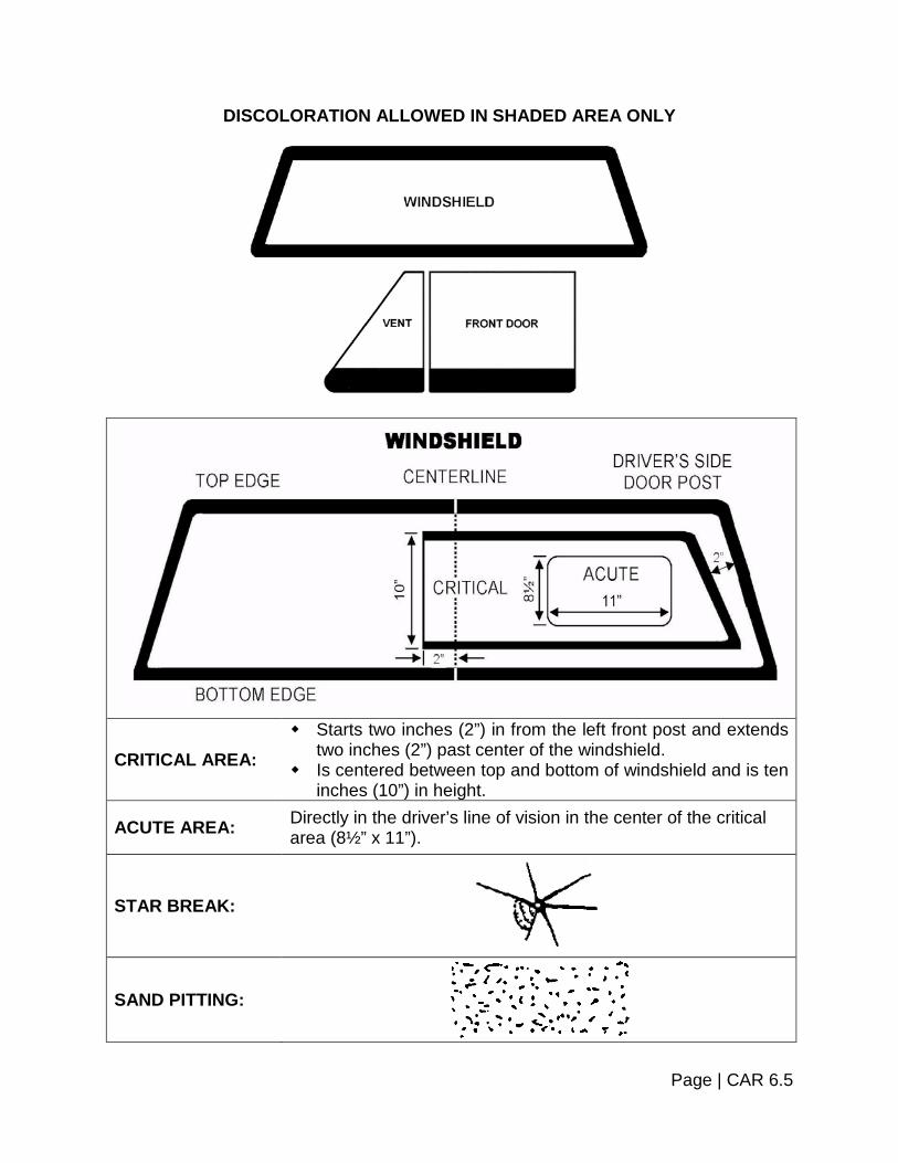
DISCOLORATION ALLOWED IN SHADED AREA ONLY
CRITICAL AREA: Starts two inches (2”) in from the left front post and extends
two inches (2”) past center of the windshield. Is centered between top and bottom of windshield and is ten
inches (10”) in height.
ACUTE AREA: Directly in the driver’s line of vision in the center of the critical area (8½” x 11”).
STAR BREAK:
SAND PITTING:
Page | CAR 6.5

CRACKS:
BULL’S EYE: (Non-vented or circular chips)
STONE NICKS OR CHIPS:
ADDITIONAL GLAZING INFORMATION Glazing Material Position Markings: The numbers on the chart below indicate the numerical markings following the letters AS, which should be found on glazing materials in the positions indicated. These numbers come from American National Standards Institute (ANSI) Glazing Standard Z26.1 (1977) and the meaning of each item as follows: Position Number Description
1 Safety Glazing Material for use anywhere in motor vehicle. 2 Safety Glazing Material for use anywhere in motor vehicle except
windshields. 3 Safety Glazing Material for use in a motor vehicle except windshields and
certain specified locations. 4 Safety Glazing Material for use in motor vehicles only in the following
locations. 5 Safety Glazing Materials for use in motor vehicles only in the following
specific locations at levels not requisite for driving visibility. 6 Safety Glazing Materials for use only in house or property carrying trailers,
in the rear windows of convertible passenger car tops, in windscreens for motorcycles, in flexible curtains or readily removable windows, or in ventilators used in conjunction with readily removable windows.
Page | CAR 6.6
Position Number Description
7 Safety Glazing Materials for use in house or property carrying trailers and at levels not requisite for driving visibility in the rear window of convertible passenger car tops, in windscreens for motorcycles, in flexible curtains or readily removable windows, or in ventilators used in conjunction with readily removable windows.
10 Bullet Resistant Glass for use anywhere in motor vehicle. 11 Bullet Resistant Glass for use anywhere in motor vehicles except
windshields.
Page | CAR 6.7


SECTION 7 – BODY AND SHEET METAL
Body components and sheet metal are subject to rejections if a condition exists which is hazardous to occupants, pedestrians or other vehicles. Care should be taken to ensure substandard repairs to these components have not been made by using items such as “duct tape”, “foam spray insulation” or other materials. All vehicles manufactured after January 1, 1968 were equipped at the factory with a left-hand exterior rear-view mirror.
EXTERIOR REAR-VIEW MIRROR Procedure: 1. From the driver's position, visually inspect exterior mirror on driver's side for a clear
and reasonably unobstructed view to the rear. 2. Look for correct location, stable mounting, cracks, sharp edges, unnecessary
protrusion and ease of adjustment. 3. Repeat visual check for exterior mirror on passenger side of vehicle, if equipped. Reject vehicle if: 1. The mirror is loose enough that rear vision could be impaired. 2. Mirror is obscured by a pillar or unwiped portion of windshield. 3. Mirror is mounted so it cannot be adjusted from driver's seated position. 4. Mirror is cracked, pitted or clouded to the extent that rear vision is obscured. 5. If rear side windows or back windows are obstructed or tinted and both exterior rear-
view mirrors are not present or do not afford a clear view to the rear. 6. If mirror is missing or cannot be adjusted.
Page | CAR 7.1

INTERIOR REAR-VIEW MIRROR
Procedure: From the driver's position, visually inspect interior mirror for proper mounting, location, cracks, sharp edges and ease of adjustment. No items should be hanging from the rearview mirror. Reject vehicle if: 1. Mirror is loosely mounted.
2. Mirror does not provide a clear view of highway.
3. Mirror is cracked, broken, has sharp edges or cannot be cleaned, such that rear
vision is obscured.
4. Mirror is very difficult to adjust or will not maintain a set adjustment. 5. Mirror is missing.
SPEEDOMETER AND ODOMETER Procedure: All motor vehicles, excluding trailers, semi-trailers and trailer coaches must be equipped with a speedometer and odometer so connected to the vehicle as to render both operable. The dial and calibrations on the speedometer shall be legible and unobstructed from the view of the operator of the vehicle. Reject vehicle if: Speedometer and/or odometer is not operational.
WINDSHIELD WIPERS U.S. vehicles produced after January 1, 1969 must be equipped with wiper systems capable of operating at two (2) or more speeds. A cycle shall consist of blade movement from one extreme of the wiper pattern to the other and return.
Page | CAR 7.2

Equipment: Source of clean water and a contact pressure-measuring device (recommended only). Procedure: 1. Inspect for satisfactory operation. (If vacuum operated, engine must be idling and
control full on.)
a. Windshield must be free of insects, oil film or other foreign matter, and must be continuously wet when tested.
2. Inspect for damaged, torn or hardened rubber elements of blades. 3. Inspect for damaged metal parts of wiper blades or arms. 4. Inspect for proper contact of blades with windshield. 5. Raise arm away from windshield and release. Arm should return to original position
and wiper blade should contact the windshield firmly.
6. Recommend replacement if arm fails to meet recommended pressure of one (1) once per inch of blade length by more than twenty percent (20%).
Reject vehicle if: 1. Windshield wipers are not operational.
a. If the vehicle is equipped with a rear window wiper, this wiper is not required to be operational provided the vehicle is equipped with a securely attached mirror on each side, however, it is a recommended best practice the wiper functions.
b. If the vehicle is equipped with headlamp wipers, these wipers are not required to
be operational; however, it is a recommended best practice the wipers function. 2. Wipers do not operate at a minimum speed of forty-five (45) cycles per minute, on
one (1) of the speed settings. 3. Vehicles produced after January 1, 1969, do not have two (2) or more speed
systems. 4. Blades smear or severely streak windshield after five (5) cycles. 5. Blades show signs of physical breakdown of rubber wiping element. 6. Parts of blades or arms are missing or are severely damaged.
Page | CAR 7.3
7. Arm fails to return to original position or the blade fails to contact the windshield firmly.
WINDSHIELD WASHER
Procedure: If the vehicle is equipped with a windshield washer system, inspect for proper operation of hand or foot control and an effective amount of fluid delivered to the outside of the windshield. Note: System must function when temperature is both above and below the
freezing point of water. If fluid level is low, advise driver. Reject vehicle if: 1. System fails to function.
2. Fluid in system is frozen.
3. System is not capable of cleaning an effective wash area.
PROTRUDING METAL Body exterior components and sheet metal parts, if damaged and/or dislocated so that they protrude from the vehicle to present a safety hazard to occupants, pedestrians or other vehicles; may be cause for rejection of the vehicle. Procedure: Inspect for torn metal parts, moldings and rust holes with sharp/jagged edges which may protrude from vehicle and cause a hazard to occupants or pedestrians. Reject vehicle if: 1. Torn metal, glass or other loose or dislocated parts protrude from the surface of the
vehicle causing a safety hazard to pedestrians or cyclists. 2. Body and/or sheet metal exhibits rust holes with sharp/jagged edges which may
cause a hazard to occupants or pedestrians.
Page | CAR 7.4

BUMPERS
Procedure: Inspect bumpers for hazardous condition or unsafe mounting. Note: If not original equipment, refer to “Bumpers” in Section 10. Trucks are exempt
when not manufactured with bumpers. Reject vehicle if: 1. The bumper is badly misplaced, loosely attached or a broken or torn portion is
protruding, creating a hazard. 2. The bumper is not of a type installed by the manufacturer or suitable material
capable of absorbing a reasonable impact. Advise driver if: Bumper is loose.
BUMPER HEIGHT Equipment: A yardstick or equivalent. Procedure: With vehicle on a level surface, measure the height of both front and rear bumpers to both top and bottom of horizontal bumper bar. Reject vehicle if: Some part of the horizontal bumper bar does not fall within manufacturer's specifications above the level ground surface. Note: For bumper height specifications, refer to “Bumpers” in Section 10.
Page | CAR 7.5
FENDERS
Procedure: Inspect for removal of front or rear fenders. Reject vehicle if: 1. Any fender has been removed.
2. Fender fails to cover the tread portion of tire.
Fender and/or fender well(s) is rusted or damaged so it allows exhaust gas to enter passenger compartment.
FLAPS Note: Refer to Section 10 of the Heavy Truck and Bus Section to determine if mud
flaps are required. Although the information is located in the Heavy Truck and Bus Section, the same formula is applicable to any vehicle with truck plates, including pickup trucks.
DOORS
Procedure: Inspect door latches, locks, hinges and handles for proper operation, fastening, bad adjustment, broken or missing components. (Try doors and locks.) Reject vehicle if: Doors or door parts are missing, broken, sagging so the door cannot be tightly closed or opened from both the inside and outside. Advise driver if: Door latching device is out of adjustment so extra effort is required to close. Note: Law enforcement vehicles used to secure persons may have inside rear door
handles removed.
Page | CAR 7.6
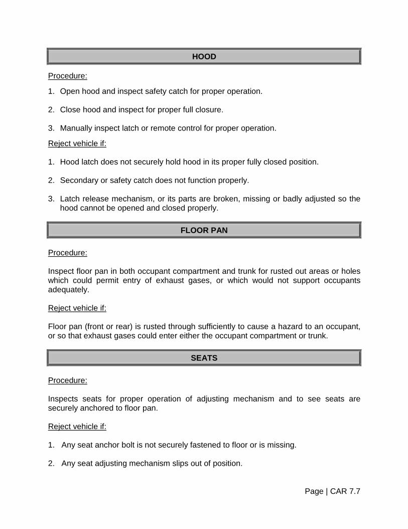
HOOD Procedure: 1. Open hood and inspect safety catch for proper operation.
2. Close hood and inspect for proper full closure.
3. Manually inspect latch or remote control for proper operation. Reject vehicle if: 1. Hood latch does not securely hold hood in its proper fully closed position.
2. Secondary or safety catch does not function properly.
3. Latch release mechanism, or its parts are broken, missing or badly adjusted so the hood cannot be opened and closed properly.
FLOOR PAN
Procedure: Inspect floor pan in both occupant compartment and trunk for rusted out areas or holes which could permit entry of exhaust gases, or which would not support occupants adequately. Reject vehicle if: Floor pan (front or rear) is rusted through sufficiently to cause a hazard to an occupant, or so that exhaust gases could enter either the occupant compartment or trunk.
SEATS Procedure: Inspects seats for proper operation of adjusting mechanism and to see seats are securely anchored to floor pan. Reject vehicle if: 1. Any seat anchor bolt is not securely fastened to floor or is missing. 2. Any seat adjusting mechanism slips out of position.
Page | CAR 7.7

SAFETY BELTS (MANUAL) Procedure: Inspect safety belts for frayed, split or torn webbing; malfunctioning webbing; malfunctioning buckles or retractors; loose or damaged anchorage's or floor pan. Reject vehicle if: 1. Seat belt webbing is frayed, split or worn. 2. Belt buckles do not operate properly. 3. Belt anchorage's are loose, badly corroded, missing or not fastened to belt. 4. Belt mounting surfaces are badly deformed, damaged or corroded.
SAFETY BELTS (MOTORIZED) Procedure: Actuate motorized belt by entering vehicle and turning ignition key to the “ON” position with door closed. Reject vehicle if: 1. Seat belt does not move and secure in locked position properly. 2. Indicator lamp continues to flash. Advise driver if: Seat belts are on floor, tucked under the seat or are obviously not being used.
AIR BAG READINESS LIGHT Note: Airbags may be equipped with an on/off switch if the vehicle owner can
produce a Federal Exemption. Procedure: Inspect Air Bag Readiness by turning ignition key to the “ON” position.
Page | CAR 7.8

Reject vehicle if: 1. If the air bag indicator fails to light, or continually flashes, or if five (5) sets or five (5)
"beeps" are heard (concurrent with indicator failing to light). 2. If the air bag indicator fails to light or continuously flashes or illuminates.
SUN VISOR
Procedure: Inspect sun visor for broken, bent, loose parts which prevent the visor from being positioned; or for visor which will not stay in a set position. Reject vehicle if: Driver visor is missing. Advise driver if: Visor cannot be positioned to protect driver's eyes from sun, or if vibration from running engine causes visor to move from set position.
WINDSHIELD DEFROSTER All vehicles produced after January 1, 1964 must be equipped with windshield defroster systems. Procedure: Turn on windshield defroster fan and inspect for heated air blowing over inside of the windshield, covering areas directly in front of the driver and the front seat passenger. (Engine must be warm and all elements of the defroster system must be on). Reject vehicle if: 1. Defroster fan fails to function.
2. Fan functions but a stream of air cannot be "felt" blowing against the proper area of
the windshield. (Ribbons may be useful in checking air movement).
Page | CAR 7.9

FRAME OR UNI-BODY INTEGRITY
Procedure: 1. With the vehicle on a lift or on jacks, inspect frame, cross members or uni-body for
broken, cracked or severely rusted areas. 2. If so equipped, check front and/or rear sub-frame assemblies. Reject vehicle if: Any structural part of the undercarriage is broken, cracked or so severely rusted so as to cause a hazard.
TRUCK CAPS AND BED LINERS Procedure: Inspect pickup truck caps, bed liners, and any associated fastening devices. Reject vehicle if: 1. Cap or bed liner is not securely attached.
2. If fasteners are loose, rusted or worn to an extent that allows the cap or liner to
become disconnected from the vehicle by the wind or other forces.
Page | CAR 7.10


SECTION 8 – EXHAUST SYSTEM
The exhaust system includes the piping leading from the flange or the exhaust manifold to and including the mufflers, resonators, catalytic converter and the tail piping. Procedure: 1. Visually examine mufflers, resonators, catalytic converters, tail pipes, exhaust pipes
and supporting hardware while vehicle is on a lift.
2. Rusted or corroded surfaces should be given particular attention. Note: Holes in the system made by the manufacturer for drainage are not cause
for rejection. Reject vehicle if: 1. Vehicle has no muffler or catalytic converter (required if installed as original
equipment by Manufacturer). 2. There are loose or leaking joints. 3. There are holes caused by corrosion, leaking seams or patches on exhaust pipe,
muffler, catalytic converter or tail pipe. 4. Tail pipe end is pinched, plugged or crushed which would restrict the exhaust flow. 5. Elements of system are not securely fastened. 6. There is a muffler cutout or similar device that allows excessive noise. 7. Any part of system passes through occupant compartment. 8. Does not discharge exhaust fumes at proper location. Advise driver if: There is excessive rust or corrosion. Note: Exhaust systems on passenger vehicles and pick up trucks shall discharge
the exhaust fumes at a location to the rear of the vehicle body or direct the exhaust fumes outward from the side of the vehicle body at a location rearward of any operable side windows. Vehicles in which the exhaust systems are manufactured with a different configuration are also acceptable as long as the exhaust systems are original factory equipment and have not been altered in any way.
Page | CAR 8.1

Note: If you are unsure whether the vehicle you are inspecting was manufactured
with a catalytic converter refer to Section 11 ~ Emission Control Systems.
Page | CAR 8.2


SECTION 9 – FUEL SYSTEM
The fuel system includes the fuel tank(s), fuel pump(s), carburetor or fuel injection system and necessary piping to carry the fuel from the tank to the engine fuel delivery system. Note: Vehicles with pressurized fuel systems (e.g., most vehicles equipped with fuel
injection systems) should be examined with the engine running.
FUEL TANK Procedure: Visually examine the fuel tank, fuel tank support straps, filler tube (rubber, plastic, metal) tube clamps, fuel tank vent holes or tubes, filler housing drain, overflow tubes and filler cap. Note: "Standard Equipment" and "Properly Equipped" as applied to a motor vehicle
shall include only such motor fuel tank or tanks as are regularly installed by the manufacturer.
Reject vehicle if: 1. Any part of system is not securely fastened. 2. There is vapor or liquid fuel leakage caused by deterioration at any point in the
system. 3. Fuel tank filler cap is missing. 4. Fuel tank is an auxiliary or added tank, if the primary tank has been removed or is
not operational. 5. Fuel hoses or tubes are contacting moving components.
FUEL CAP Procedure: Visual examination of the fuel cap is required.
Page | CAR 9.1

Reject vehicle if: Cap is missing or defective.
Page | CAR 9.2


SECTION 10 – RECONSTRUCTED AND/OR SPECIAL MOTOR VEHICLES
MINIMUM REQUIREMENTS FOR CONSTRUCTION AND EQUIPMENT OF SPECIAL MOTOR VEHICLES: Definition: Passenger vehicles and trucks with unladen weight of 10,000 pounds or less equipped with two (2) or more axles having at least two (2) wheels per axle. The term "Special Motor Vehicles" shall include the following types:
Specific questions regarding definitions or equipment should be routed to the Inspector closest to your area.
DEFINITIONS Antique: These can be exhibition vehicles as above but need be only a vehicle
twenty-five (25) years old or older. Exhibition: Any motor vehicle maintained solely for use as an exhibit at club
activities, parades, and other functions of public interest. (These could include trailers, as well as other vehicles and might be early model or late model vehicles and vehicles of special design; i.e., trick cars, or replicas of railroad locomotives or railroad box cars).
Kit-Car: "Kit-car" shall mean a commercially manufactured body and/or body and
frame which may resemble a regularly manufactured vehicle or whose body may be of a unique design but is manufactured to fit on a commercially manufactured frame.
Neighborhood Electric Vehicle: “Neighborhood Electric Vehicle” means a self-
propelled, electrically-powered motor vehicle which: Is emission free;
Is designed to carry four or fewer persons;
Is designed to be, and is, operated at speeds of 25 MPH or less;
Has at least four wheels in contact with the ground;
Has a gross vehicle weight rating less than 3,000 pounds;
Conforms to minimum safety equipment requirements as adopted in the Federal Motor Vehicle Safety Standard No. 500, Low Speed Vehicles (49 CFR. 571.500).
Replica: "Replica" means a body or frame commercially manufactured which
resembles that of the original vehicle or duplicated vehicle and which retains the basic style and dimensions as originally manufactured and whose major
Page | CAR 10.1

components such as grill shell, hood and doors are readily interchangeable with the original component.
Street Rod: "Street Rod" shall mean a vehicle, the body and frame of which were
manufactured prior to the year 1949 and which has been modified for safe road use, or a replica thereof which resembles that of an original pre 1949 vehicle and has also been modified for safe road use. For the purposes of this Section "modified" means, but is not limited to, a substantial and material alteration or replacement of the engine, drive-train, suspension or brake system or alteration of the body which may be chopped, channeled, sectioned, filled or otherwise changed dimensionally from the original manufactured body.
Any such modification may be made only if said modification equals, improves or enhances the safety aspects of the original equipment so modified.
Type I: Those vehicles which are restored to their original body configuration and
which may contain changed steering, brake, power train or suspension systems, and may include "Street Rods", "Replicas of Street Rods", "Replicas" or "Kit-cars".
Type II: Those vehicles changed from the recognized vehicle manufacturer's
original body configuration but which retain the general appearance, including changes to the body chassis or engine of the original vehicle. This type may also include changes and modifications to engine, chassis, brake system, power train, steering and suspension systems, and may include "Street Rods", "Replicas of Street Rods", "Replicas" or "Kit-cars".
Type III: Other than Type I and Type II special vehicles, those vehicles custom built
with fabricated parts, or parts taken from existing vehicles.
EQUIPMENT REQUIRED Antique: Need only exhibit the equipment originally installed by the manufacturer,
and all such equipment shall be in proper mechanical condition. Exhibition: These vehicles are generally very unique and the specific equipment
required would include at a minimum; adequate tires, brakes, fuel and exhaust systems.
Homebuilt Vehicles: All homebuilt vehicles 1996 and newer registered as a
pleasure car or truck must meet all the requirements of the inspection manual, including OBD II. Homebuilt vehicles registered for a special purpose, as listed under definitions are exempt from OBD II, but must still include at a minimum; adequate tires, brakes, fuel and exhaust systems.
Kit-Car: These vehicles must meet all the criteria as specified in Section 10 ~
Reconstructed or Special Motor Vehicles".
Page | CAR 10.2

Neighborhood Electric Vehicles (NEVs): NEVs must conform to the minimum
safety equipment requirements as adopted in the Federal Motor Vehicle Safety Standard No. 500, Low Speed Vehicles (49 CFR. 571.500). NEVs must be equipped with the following functional equipment:
Headlamps Stop lamps Parking/Hand brakes Tail lamps Rear-view mirrors Turn signals Reflex reflectors Vehicle identification numbers Seat belts Windshields
Replica: These vehicles are often equipped in the same manner and with the same
components as the original duplicated vehicle and should be inspected using the same criteria as for the original vehicle.
Street Rod: These vehicles must meet all the criteria specified in Section 10 ~
"Reconstructed and/or Special Motor Vehicles".
"Street Rods" may be inspected using the criteria specified below only after having been certified as such by a person authorized by the Commissioner to make such determination. At the time of inspection, the owner or operator must present the certificate of verification properly executed.
You may call the inspector closest to you or the Inspections Unit in Montpelier to obtain the name, phone number and address of the closest authorized person to obtain certification as a "Street Rod".
BODY REQUIREMENTS
DEFROSTER AND DEFOGGING DEVICE
Every special vehicle manufactured in 1964 or later shall be equipped with a device capable of defogging or defrosting the windshield.
DOOR LATCHES Every special vehicle equipped with doors leading directly into a compartment that contains one or more seating accommodations shall be equipped with mechanically or electrically activated door latches which firmly and automatically secure the door when pushed closed and which allow each door to be opened from the inside by the activation of a convenient lever, handle or other suitable device.
Page | CAR 10.3

FLOOR PAN
Every special vehicle shall be equipped with a floor pan under the entire passenger-carrying compartment. The floor pan shall support the weight of the number of occupants the vehicle is designed to carry. The floor pan shall be so constructed that it prevents the entry of exhaust fumes.
GLAZING Every special vehicle shall be equipped with a laminated safety glass windshield that complies with the provisions appearing in the current ANSI Z 26.1 Standard, AS1 or AS10. The windshield shall be in such a position that it affords continuous horizontal frontal protection to the driver and front seat occupants. The minimum vertical height of the unobstructed windshield glass shall be not less than six inches (6”), or as originally equipped by a recognized manufacturer.
SIDE AND REAR GLASS
These items are not required but if they are present, they must comply with the provisions of current ANSI Z 26.1 Standard. (AS1, AS2, AS4, AS6, AS10 or AS11.) Glass to the rear of the driver may be Lexan or tempered glass in a "Street Rod".
WINDOW TINTING Shall be allowed only as permitted in Section 6 of the Pleasure Car and Light Truck Section.
CRACKS, CHIPS OR DISCOLORATION Shall be allowed only as permitted in Section 6 of the Pleasure Car and Light Truck Section.
DRIVER VISIBILITY The vehicle shall be provided with a windshield and side windows or openings which allow the driver a minimum outward horizontal vision capability ninety degrees (90°) each side of a vertical plane passing through the fore and aft centerline of the vehicle. This range of vision may be interrupted by window framing not exceeding two inches
Page | CAR 10.4
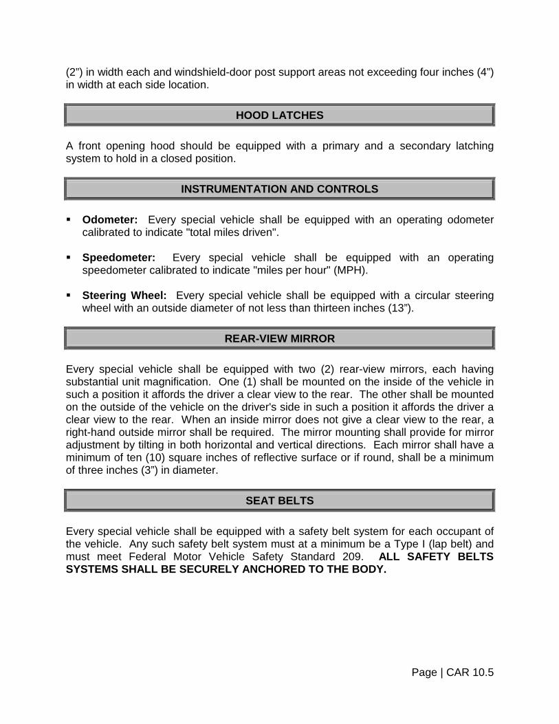
(2”) in width each and windshield-door post support areas not exceeding four inches (4”) in width at each side location.
HOOD LATCHES A front opening hood should be equipped with a primary and a secondary latching system to hold in a closed position.
INSTRUMENTATION AND CONTROLS Odometer: Every special vehicle shall be equipped with an operating odometer
calibrated to indicate "total miles driven". Speedometer: Every special vehicle shall be equipped with an operating
speedometer calibrated to indicate "miles per hour" (MPH). Steering Wheel: Every special vehicle shall be equipped with a circular steering
wheel with an outside diameter of not less than thirteen inches (13”).
REAR-VIEW MIRROR Every special vehicle shall be equipped with two (2) rear-view mirrors, each having substantial unit magnification. One (1) shall be mounted on the inside of the vehicle in such a position it affords the driver a clear view to the rear. The other shall be mounted on the outside of the vehicle on the driver's side in such a position it affords the driver a clear view to the rear. When an inside mirror does not give a clear view to the rear, a right-hand outside mirror shall be required. The mirror mounting shall provide for mirror adjustment by tilting in both horizontal and vertical directions. Each mirror shall have a minimum of ten (10) square inches of reflective surface or if round, shall be a minimum of three inches (3”) in diameter.
SEAT BELTS Every special vehicle shall be equipped with a safety belt system for each occupant of the vehicle. Any such safety belt system must at a minimum be a Type I (lap belt) and must meet Federal Motor Vehicle Safety Standard 209. ALL SAFETY BELTS SYSTEMS SHALL BE SECURELY ANCHORED TO THE BODY.
Page | CAR 10.5

WINDSHIELD WIPERS
Every special motor vehicle shall be equipped with at least one (1) windshield wiper with a blade not less than five and one-half inches (5½”) long and properly centered upon the driver's position which effectively clears the windshield area directly in front of the driver. The operation of the windshield wiper(s) shall be controlled by the driver from within the vehicle and shall be electrically or vacuum operated.
ACCELERATOR CONTROL SYSTEM Every special motor vehicle shall be equipped with an accelerator control system that returns the engine throttle to an idle position when the driver removes the actuating force from the accelerator control.
BRAKES: SERVICE BRAKES Every special motor vehicle shall be equipped with hydraulic brakes acting on all wheels. The service brakes, upon application, must be capable of: Meeting all the requirements as specified in Section 4 of the Pleasure Car and Light Truck Section.
CHASSIS REQUIREMENTS
PARKING/HAND BRAKE
Shall meet all the requirements of Section 4 of the Pleasure Car and Light Truck Section.
BUMPERS 1. Every motor vehicle registered in this state and operated upon the public streets or
highways shall be equipped with front and rear bumpers if such vehicle was equipped with such bumpers as standard equipment except that bumpers shall be optional on street rods as defined earlier in this section.
2. Bumpers must extend no less than the width of their respective wheel track
distances. The horizontal bumper or customized bumper or grill bar structure shall be at least four and one- half inches (4½”) in vertical height, centered on the
Page | CAR 10.6
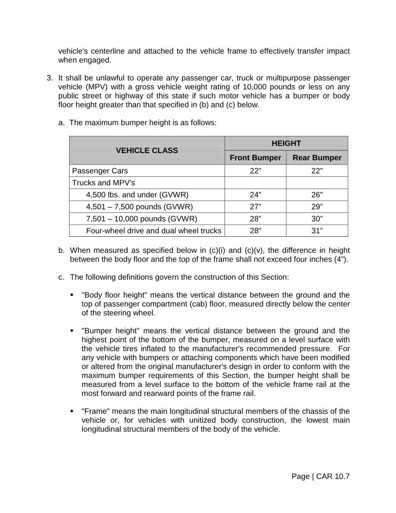
vehicle's centerline and attached to the vehicle frame to effectively transfer impact when engaged.
3. It shall be unlawful to operate any passenger car, truck or multipurpose passenger
vehicle (MPV) with a gross vehicle weight rating of 10,000 pounds or less on any public street or highway of this state if such motor vehicle has a bumper or body floor height greater than that specified in (b) and (c) below. a. The maximum bumper height is as follows:
VEHICLE CLASS HEIGHT
Front Bumper Rear Bumper Passenger Cars 22” 22” Trucks and MPV's
4,500 lbs. and under (GVWR) 24” 26” 4,501 – 7,500 pounds (GVWR) 27” 29” 7,501 – 10,000 pounds (GVWR) 28” 30” Four-wheel drive and dual wheel trucks 28” 31”
b. When measured as specified below in (c)(i) and (c)(v), the difference in height
between the body floor and the top of the frame shall not exceed four inches (4”). c. The following definitions govern the construction of this Section:
"Body floor height" means the vertical distance between the ground and the
top of passenger compartment (cab) floor, measured directly below the center of the steering wheel.
"Bumper height" means the vertical distance between the ground and the highest point of the bottom of the bumper, measured on a level surface with the vehicle tires inflated to the manufacturer's recommended pressure. For any vehicle with bumpers or attaching components which have been modified or altered from the original manufacturer's design in order to conform with the maximum bumper requirements of this Section, the bumper height shall be measured from a level surface to the bottom of the vehicle frame rail at the most forward and rearward points of the frame rail.
"Frame" means the main longitudinal structural members of the chassis of the
vehicle or, for vehicles with unitized body construction, the lowest main longitudinal structural members of the body of the vehicle.
Page | CAR 10.7
"GVWR" means the manufacturer's gross vehicle weight rating whether or not the vehicle is modified by use of parts not originally installed by the manufacturer.
Height of the "top of the frame" means the vertical distance between the
ground and the top of the frame, measured directly below the center of the steering wheel.
"Multipurpose passenger vehicle (MPV)" means a motor vehicle with motive
power, except a trailer, designed to carry ten (10) persons or fewer which is constructed either on a truck chassis or with special features for occasional off-road operation.
"Passenger car" means a motor vehicle with motive power; except a
multipurpose passenger vehicle, motorcycle or trailer designed for carrying ten (10) persons or fewer.
"Truck" means a motor vehicle with motive power, except a trailer designed
primarily for the transportation of property or special purpose equipment.
EXHAUST SYSTEM
Every special motor vehicle shall be equipped with an exhaust system free of leaks including the exhaust manifolds (including headers), the piping leading from the flange of the exhaust manifold(s), the muffler(s) and the tail piping. Vehicles registered as “Exhibition Vehicles” are exempt from OBD II requirements. Exhaust systems on property-carrying vehicles shall discharge the exhaust fumes to the rear of that part of the vehicle designed for, and normally used for, carrying the driver and passengers. Note: Exhaust systems on passenger vehicles and pick up trucks shall discharge
the exhaust fumes at a location to the rear of the vehicle body or direct the exhaust fumes outward from the side of the vehicle body at a location rearward of any operable side windows. Vehicles in which the exhaust systems are manufactured with a different configuration are also acceptable as long as the exhaust systems are original factory equipment and have not been altered in any way.
FENDERS
All wheels of every special motor vehicle shall be equipped with fenders designed to cover the entire tire tread width that comes in contact with the road surface. Coverage of the tire tread circumference shall be from at least fifteen degrees (15°) in front to at least seventy-five degrees (75°) to the rear of the vertical center line at each wheel measured from the center of wheel rotation. At no time shall the tire come in contact
Page | CAR 10.8

with the body, fender or chassis of the vehicle. Fenders shall be optional on "Street Rods" for any model year prior to 1935.
FUEL SYSTEM Every special motor vehicle shall have all fuel system components, such as tank, tubing, hoses, clamps, etc., securely fastened to the vehicle with fasteners designed for this purpose so as not to interfere with the vehicle operation and shall be leak proof. Fuel lines shall be positioned so as not to be in contact with high temperature surfaces or moving components. The fuel tank must be vented to the outside of the vehicle and must have a sealed inlet (filler) pipe cap.
STEERING A special motor vehicle shall have no steering components extending below the wheel rims in their lowest position. The use of unconventional steering components such as chain drive, sprockets or electric solenoids shall be prohibited. The steering system shall remain unobstructed when turned from lock to lock. While the vehicle is in a sharp turn at a speed between 5 MPH and 15 MPH, release of the steering wheel shall result in a distinct tendency for the vehicle to increase its turning radius. (Stability tests shall be performed on a dry, level concrete or asphalt road having no loose surface contaminant and the vehicle tires shall be inflated to the recommended pressure in accordance with the tire load per Federal Motor Vehicle Safety Standard No. 109. The vehicle shall contain a front seat passenger or a simulated equivalent to one hundred and fifty (150) pounds weight secured to the seat in addition to the driver.)
SUSPENSION No special motor vehicle shall be constructed or loaded so the weight on the wheels of any axle is less than thirty percent (30%) of the gross weight of the vehicle. Special vehicles shall be equipped with a damping device at each wheel location providing a minimum relative motion between the unsprung axle and wheel and the chassis body of plus and minus two inches (2”). When each corner of the vehicle is depressed and released, the damping device shall stop vertical body motion within two (2) cycles.
Page | CAR 10.9

SCRUB LINE
On "Street Rods" as defined earlier in this section, on both the front and rear suspension of the vehicle, stretch a taut string from the bottom of each wheel rim to the bottom of each of the other three (3) tires at the road surface. If any part of the steering, suspension or chassis is below this string, the vehicle will not pass inspection. Allow an additional one-quarter of an inch (¼”) assuming the tire will not come off the rim if the tire should go flat. Items which may extend below the scrub line include body sheet metal, bumpers, exhaust system components, oil and transmission pans.
TIRES AND WHEELS The tires on special motor vehicles shall comply with current Federal Motor Vehicle Safety Standards and VESC-1 and VESC-7. Front tires must measure a minimum of sixty percent (60%) of the tread width of the rear tires. Front tires on street rods shall have a minimum of five inches (5”) of tread width in contact with the road surface and shall be of a type approved for use on pleasure cars or trucks. Tires shall meet all other standards as specified in Section 2 of the Pleasure Car and Light Truck Section.
ELECTRICAL SYSTEMS REQUIREMENTS
DIMMER SWITCH
The headlamp circuit shall be equipped with a driver-controlled switch used to select the high or low beam.
HEADLAMP SWITCH The headlamp switch must activate the headlamps, tail lamps, license plate lamp, parking lamps and the speedometer illumination lamp(s).
HEADLAMP SYSTEM Every special motor vehicle shall be equipped with headlamp units as described in Section 5 of the Pleasure Car and Light Truck Section. The headlamps shall be mounted not less than twenty-four inches (24”) or more than fifty-four inches (54”) above the road surface when measured to the headlamp center. Lamp sub-body(ies) shall be constructed with adequate adjustment to afford aiming of the headlamp(s).
Page | CAR 10.10
HIGH BEAM INDICATOR
An indicator shall be provided to show the driver when the upper beam of the headlamp system is energized. The indicator shall emit a light other than white plainly visible to the driver under normal driving conditions.
HORN Every special vehicle shall be equipped with a horn that is electrically operated and that will emit a minimum sound level of ninety-two decibels (92 db) measured at a distance of two hundred feet (200’) directly in front of the vehicle under clear weather conditions. The switch used to actuate the horn shall be easily accessible to the driver when operating the vehicle.
LICENSE PLATE LAMP At least one (1) white lamp shall be provided at the rear license plate to illuminate the plate.
PARKING LAMPS Two (2) amber or white parking lamps in compliance with SAE J222 shall be mounted on the front, one (1) on each side and equidistant from the vertical centerline of the vehicle, at the same height, and as far apart as practical. The parking lamps shall be mounted not less that fifteen inches (15”), or more than seventy-two inches (72”), above the roadway.
REFLEX REFLECTORS Two (2) red Class A reflectors in compliance with SAE J594d shall be mounted on the rear symmetrically disposed about the vertical centerline. The reflex reflectors shall be mounted not less than fifteen inches (15”), or more than sixty inches (60”), above the roadway. (Combination lighting devices are acceptable.)
STOP LAMPS Two (2) red stop lamps in compliance with SAE Standard J586b shall be mounted on the rear, one (1) on each side equidistant from the vertical centerline of the vehicle, at the same height, and as far apart as practical.
Page | CAR 10.11

Type I or Type II vehicles, which were originally equipped with only one (1) stop lamp need not be equipped with two (2) stop lamps providing the original lamp is located in accordance with the original design configuration. The stop lamps shall be mounted not less than fifteen inches (15”), or more than seventy-two inches (72”), above the roadway. (Combination lighting devices are acceptable.)
TAIL LAMP SYSTEM Two (2) red lamps in compliance with SAE Standard J585c shall be mounted on the rear, one (1) on each side equidistant from the vertical centerline, and the same height, and as far apart as practical. The tail lamps shall be mounted not less than fifteen inches (15”), nor more than seventy-two inches (72”) above the roadway. Type I vehicles, which were originally equipped with only one (1) tail lamp need not be equipped with two (2) tail lamps providing the original lamp is located in accordance with the original design configuration. (Combination lighting devices are acceptable.)
TURN SIGNAL INDICATOR If the front signal lamp(s) are not readily visible to the driver, there shall be an illuminated indicator to give a clear and unmistakable indication the turn signal system is turned on. The illuminated indicator shall consist of one (1) or more bright lights flashing at the same frequency as the signal lamps and it shall emit a light other than white. (Combination lighting devices are acceptable.)
TURN SIGNAL LAMPS Two (2) Class A red or amber turn signal lamps and two (2) Class A amber turn signal lamps in compliance with SAE J588d shall be mounted as follows: At or near the front, one (1) amber lamp on each side equidistant from the vertical centerline, at the same height, and as far apart as practical. On the rear, one (1) red or amber lamp on each side equidistant from the vertical centerline, at the same height, and as far apart as practical. All turn signal lamps shall be mounted not less than fifteen inches (15”), or more than eighty-three inches (83”), above the roadway. Type I vehicles which were originally equipped with only one (1) tail lamp need not be equipped with two (2) tail lamps providing the original lamp is located in accordance with the original design configuration. (Combination lighting devices are acceptable.)
TURN SIGNAL SWITCH Every special vehicle shall be equipped with a switch controlled by the operator of the vehicle that shall cause the turn signal lamps to function. The switch shall be self-canceling and capable of cancellation by a manually operated control.
Page | CAR 10.12

REPLACEMENT LENSES On "Street Rods" as defined earlier in this section, where an original lens cannot be found to replace a cracked or defective stop, tail or rear lens it shall be acceptable to replace the lens with a portion of a similarly approved lens cut and shaped to the appropriate size so long as the original lens was of an approved type.
AUTOMATIC TRANSMISSION Automatic transmission only – neutral safety starting switch. Determine the starter operates with gear selector in "P" or "N" only. If the starter operates in any gear other than "Park" or "Neutral" the vehicle cannot pass inspection.
ENGINE ENCLOSURE Rear mounted engines: Must be equipped with an enclosure providing coverage for all pulleys, belts and external moving engine parts. The cover must be made of rigid material and completely cover all moving parts. If a flat cover is used, it must extend at least one inch (1”) beyond all parts being covered. If the cover encases the moving parts, it need not extend the required one inch (1”) beyond all edges. Engines with pulleys, belts and other moving parts encased need only enclose the air intake with rigid mesh material. The openings in the mesh shall not exceed one-quarter of an inch (¼”). Front mounted engines: If the hood is removed from vehicles with a front mounted engine, the fan must be enclosed within a shroud of substantial rigid material to prohibit anyone from inadvertently being injured and to prevent the fan from flying up from the engine compartment should it become loose.
FIREWALL The vehicle must be equipped with a firewall constructed of a metal or comparable insulated fire retarding material protective barrier to separate the engine compartment from the passenger compartment, capable of withstanding forces normally encountered in collisions and designed to retard the spread of fire from the engine compartment into the passenger compartment.
Page | CAR 10.13


SECTION 11 – EMISSION CONTROLS
CATALYTIC CONVERTER
Procedure: If the vehicle was originally equipped with a catalytic converter, visually examine for the presence of a properly installed catalytic converter(s) while vehicle is on a lift. Special consideration should be given to the following: 1. Many resonators or mufflers look like catalytic converters. Consult manufacturer’s
specification, if necessary, for catalytic converter location. 2. Look beyond the converter heat shield to verify the converter itself is present. 3. On many imported vehicles, the converter is located close to the engine. It may be
necessary to raise the hood to verify the converters presence. 4. Some engines have two (2) converters, one (1) on each pipe of the manifold "Y"
pipe, while others have only one (1) converter. Consult manufacturer’s specifications for design details.
5. Many "dual-bed" catalytic converters have an air injection tube installed between the
beds. This tube must be present and connected for approval. Reject vehicle if: 1. The catalytic converter is disconnected or removed. 2. When applicable, if the air supply to the converter is disconnected or removed.
c. To determine if a vehicle was originally equipped with a catalytic converter: d. Locate the VEHICLE EMISSION CONTROL INFORMATION (VECI) label found
under the hood. Vehicles built during 1966 – 1970 model years in conformity to U.S. standards may not have this label, but can be easily identified by a Department of Transportation (DOT) doorpost label indicating conformity with Federal safety standards. All 1971 and newer cars, light-duty trucks or multipurpose vehicles are required to have this label placed in the engine compartment. This label, should indicate "Catalyst" if the vehicle was originally equipped with a converter.
e. If unable to locate the VECI label, consult the manufacturer.
Page | CAR 11.1

f. In some instances, especially in the cases of pickup trucks and vans, it may be
necessary to verify the gross vehicle weight rating (GVWR) of the vehicle. The GVWR can be determined by opening the driver’s door and reading the label on the edge of the doorpost.
g. If it cannot be determined if the vehicle was originally equipped with a catalytic
converter, contact the manufacturer for specifications. 3. If the catalytic converter shows signs of tampering.
FUEL CAP FILLER TEST Procedure: Visual examination of the fuel cap is required. Reject vehicle if: Fuel cap is missing or defective
ON-BOARD DIAGNOSTICS (OBD II) TEST Procedure: Conduct a visual and electronic examination of the on-board diagnostic (OBD) system on all 1996 and newer gasoline powered vehicles with a gross vehicle weight rating (GVWR) of 8,500 pounds or less, and all 1997 and newer diesel powered vehicles with a GVWR of 8,500 pounds or less. Record the results of the OBD inspection on the OBD Inspection Test Form (Form TA- VN-208). 1. Applicability:
For gasoline powered vehicles, confirm vehicle is model year 1996 or newer with a GVWR of 8,500 pounds or less. For diesel powered vehicles, confirm vehicle is model year 1997 or newer with a GVWR of 8,500 pounds or less. GVWR can be found on the driver’s side doorpost label. To determine model year of vehicle, use either the registration certificate or the vehicle emission control information label located under the hood. Do not use date of manufacture to determine vehicle model year, as date of manufacture and model year are not necessarily the same.
Page | CAR 11.2
2. Visual Inspection of Malfunction Indicator Light (MIL): Note: The “Check Engine Light”, “Malfunction Indicator Light” (MIL) may
illuminate on some hybrid electric vehicles as the result of a code(s) unrelated to vehicle safety and/or engine emissions. It is the inspection mechanic’s responsibility to determine if the illuminated Malfunction Indicator Light (MIL) is related to vehicle safety and/or engine emissions.
a. Determine if the instrument panel Malfunction Indicator Light (MIL) illuminates
when the ignition key is turned to the “Key on, Engine off” position.
b. The Malfunction Indicator Light (MIL) is the official term for the warning light that is illuminated by the vehicle’s OBD system when a malfunction occurs. Depending on the vehicle make, the MIL will either display “Service Engine Soon,” “Check Engine,” the international engine symbol along with the word “Check,” or some combination of these. The MIL must come on when the ignition key is turned to the “Key on, Engine off” position. This is to allow technicians to check that the MIL is capable of illuminating if a malfunction were to occur. On most vehicles, the MIL will stay illuminated as long as the key is in the “Key on, Engine off” position. However, on some vehicles (e.g., Chrysler, Honda) the MIL will illuminate very briefly when the key is turned to the “Key on, Engine off” position and then will go out. This is acceptable. Be sure to be watching for the MIL to illuminate when you turn the key to the “Key on, Engine off” position, or you may miss it.
c. Start the engine. Determine if the MIL is illuminated while the engine is running.
Shut off the engine.
d. If the MIL is illuminated while the engine is running, the vehicle’s OBD system has determined that there is a problem with the vehicle.
3. Scan Tool Check:
a. With the ignition key off, locate the vehicle’s diagnostic connector and plug an acceptable scan tool into the vehicle’s diagnostic connector.
The diagnostic connector is required to be located between the driver’s end of the instrument panel and approximately one foot (1’) beyond the vehicle centerline, on or below the instrument panel. On most vehicles, the connector is located beneath the instrument panel, near the steering column. Also, on most vehicles the connector is exposed, but on some vehicles the connector is behind a small panel, which must be opened to gain access. On a few vehicles, the connector may be more difficult to locate. An acceptable scan tool is a scan tool which complies with SAE Recommended Practice J1978, or has been approved by the Commissioner of Motor Vehicles.
Page | CAR 11.3
b. Start the engine. Use the scan tool to check the readiness status of the vehicle’s OBD monitors.
The purpose of the readiness status check is to determine if the vehicle’s OBD system has tested all emission control components or systems. Note that not all vehicles will be equipped with all eleven components or systems. If a vehicle is not equipped with a particular component or system, the scan tool will either not list those items, or will indicate “not available”, “not supported”, or other similar wording. If any of the eleven components or systems are not ready, the OBD system has not yet completed testing of those items, and malfunctions may be present, but not yet identified. In that case, the current state of that particular component or system is undetermined. Some of the eleven components or systems are continuously tested by the vehicle’s OBD system, while others are tested only under specific vehicle operating conditions. Once testing of a component or system by the vehicle’s OBD system is complete, the readiness status for that particular component or system will be set to “ready”. Normally, the readiness status of all components or systems will be “ready”. However, if the vehicle’s battery has been recently disconnected, or if diagnostic trouble codes (DTCs) have recently been cleared with a scan tool, components or systems will be set to “not ready”.
c. With the engine still running, use the scan tool to identify MIL status. The MIL will
either be commanded “ON” or “OFF” by the vehicle’s OBD system.
The purpose of checking MIL status using the scan tool is to determine if the vehicle’s OBD system has commanded the MIL to turn on due to a malfunction. This allows you to determine if there is a malfunction even if the MIL is not actually illuminated because of a problem with the MIL itself, or due to tampering with the MIL. It is very important for this step to be done with the engine running, because certain vehicles will incorrectly fail this part of the test if done with the engine off.
d. If the MIL is commanded “OFF”, and if your visual check of the MIL showed it is
not illuminated with the engine running, shut off the engine, then disconnect the scan tool from the vehicle’s diagnostic connector.
Only complete the next step if the MIL is commanded “ON”, and/or your visual check of the MIL showed it to be illuminated with the engine running. Otherwise, completing the next step will only waste your time and possibly cause confusion for the vehicle owner/operator.
e. If the MIL is commanded “ON”, or if your visual check of the MIL showed it to be
illuminated with the engine running, use the scan tool to identify diagnostic trouble codes (DTC’s). Shut off the engine then disconnect the scan tool from the vehicle’s diagnostic connector.
Page | CAR 11.4
Reject vehicle if: 1. The diagnostic link connector has been removed, tampered with or is otherwise
inoperable. Advise the owner/operator of the need to have the vehicle serviced or repaired, and that repair costs may be covered by the vehicle manufacturer’s warranty.
2. The MIL does not illuminate at all when the ignition key is turned to the “Key on,
Engine off” position. It is acceptable for the MIL to illuminate very briefly when the key is turned to the “Key on, Engine off” position and then go out. However, if the MIL does not illuminate at all, the vehicle must be rejected. Advise the owner/operator of the need to have the vehicle serviced or repaired, and that repair costs may be covered by the vehicle manufacturer’s warranty.
The reason for rejection is because when the vehicle’s OBD system detects a
malfunction it turns the MIL on to alert the driver to a problem. However, if the MIL cannot illuminate, the driver could not be alerted to the problem.
3. The MIL is illuminated while the engine is running. Advise the owner/operator of the
need to have the vehicle serviced or repaired, and that repair costs may be covered by the vehicle manufacturer’s warranty.
The reason for rejection is because the vehicle’s OBD system has detected a
malfunction and turned on the MIL to alert the driver. 4. The Illuminated Check Engine Light (MIL) is related to vehicle safety and/or engine
emissions, in those hybrid electric vehicles referred to in the “Note”, in Step 2 of the procedure for Visual Inspection of Malfunction Indicator Light (MIL).
5. Three (3) or more of the vehicle’s OBD monitors, as indicated by the scan tool, are
not ready. Advise the owner/operator that a recently disconnected or discharged battery, or recent servicing using a scan tool may explain why the vehicle’s OBD monitors are not ready. Also advise the owner/operator the vehicle must be driven under a variety of normal operating conditions in order for the OBD monitors to become ready. These operating conditions include a mix of highway driving and stop and go, city type driving and at least one (1) overnight-off period.
The reason for rejection is because the vehicle’s OBD system has not yet
completed testing, and malfunctions may be present, but not yet identified. Exceptions: Do not reject the following vehicles if three (3) or more of the vehicle’s
OBD monitors, as indicated by the scan tool, are not ready: All new vehicles having less than 1,000 miles;
Page | CAR 11.5

1996 Chrysler (Avenger, Sebring, Talon, Cirrus, Stratus, Breeze, Intrepid, Concorde, New Yorker, LHS, Vision, Neon);
1996 Subaru (all models);
1996 – 1998 Mitsubishi (all models);
1996 – 1998 Volvo 850 (all models);
1996 – 1998 Saab (all models).
6. The MIL status, as indicated by the scan tool, is “ON”. In this case, the MIL should also be illuminated with the engine running. However, even if the MIL is not illuminated with the engine running, the vehicle must be rejected because the scan tool shows the vehicle’s OBD system had detected a malfunction and tried to illuminate the MIL.
Page | CAR 11.6


SECTION 12 – FLAPS AND FENDERS
MUD FLAPS AND FENDERS
Equipment: Measuring Device. Procedure: 1. Inspect fenders and flaps to determine they are solidly attached and of substantial
material, cover the full width of the tread to prevent throwing dirt, water or other material onto the windshield of vehicles following.
2. If a flap is required, the following standards will be followed:
The splash pans stone throw protection device shall extend laterally for at least the width of the tires and shall be composed of material or flexible materials substantial enough to withstand ripping or tearing by ordinary means, and also shall be long enough so the clearance from the ground to the bottom edge of the device shall be not more than one-half (½) of the distance from the bottom edge of the device to the center line of the rearmost axle of the vehicle. However, the bottom edge of such device need be no closer to the road than six inches (6”) when loaded.
Reject vehicle if: 1. Fenders or flaps are not solidly attached. 2. Are not constructed of substantial materials. 3. Are not of sufficient size or are not attached properly. 4. Do not meet the criteria set out in the following pictures. 5. Fenders do not cover the entire tread width. 6. Come into contact with the tire or wheel.
Page | CAR 12.1

Flaps required, as the distance from rear edge of truck body to the ground is over half (½) the distance from center of rearmost axle to rear edge of body.
Flaps required, as the distance from rear edge of fender to the ground is over half (½) the distance from center of rearmost axle to rear edge of fender.
Page | CAR 12.2


TABLE OF CONTENTS
HEAVY TRUCK AND BUS SECTION
SUBJECT PAGE NUMBER
Section 1 ~ Registration and Insurance TRK 1.1 – TRK 1.2
Section 2 ~ Wheels and Tires TRK 2.1 – TRK 2.6
Section 3 ~ Steering Mechanism and Suspension TRK 3.1 – TRK 3.8
Section 4 ~ Coupling Devices TRK 4.1 – TRK 4.4
Section 5 ~ Lighting and Electrical Systems TRK 5.1 – TRK 5.12
Section 6 ~ Vehicle Glazing (Glass) TRK 6.1 – TRK 6.3
Section 7 ~ Brake Systems TRK 7.1 – TRK 7.20
Section 8 ~ Fuel System TRK 8.1
Section 9 ~ Exhaust System TRK 9.1
Section 10 ~ Flares, Flags, Flaps and Fenders TRK 10.1 – TRK 10.2
Section 11 ~ Body and Sheet Metal TRK 11.1 – TRK 11.4
Section 12 ~ Frame TRK 12.1 – TRK 12.2
Section 13 ~ Specialized Vehicles TRK 13.1
Section 14 ~ Heavy Vehicles Excess Weight Permit Inspection and Certification TRK 14.1
Note: In addition to the materials provided in this section, Inspection
Mechanics should be thoroughly familiar with Federal Motor Carrier inspection standards. To obtain a copy of the Federal Motor Carrier inspection standards, they can be found online at www.fmcsa.dot.gov
For the purposes of this Inspection Manual, a “Heavy Truck” is
defined as A TRUCK HAVING A GROSS VEHICLE WEIGHT RATING OF 10,001 POUNDS OR MORE AS DETERMINED BY THE MANUFACTURER.


SECTION 1 – REGISTRATION
The first step in the inspection of a vehicle should be a short review of the registration, plates and insurance certificate. Agreement Among Papers:
Procedure:
Inspect registration certificate, license plates, vehicle description and vehicle identification number or numbers. Compare to determine if there is proper agreement among them.
Reject vehicle if:
1. Vehicle description or identification number is not in agreement with registration
certificate.
2. Numbers on license plates are not in agreement with numbers on registration certificate.
3. Registration certificate is lost or missing.
Note: Vehicle registrations obtained via the Vermont DMV website are valid
for a period of 10 days from the date of issue and serve as temporary registrations. These are permissible for inspection purposes.
4. If VIN tag on vehicle’s dash area has been removed, tampered with or not visible.
Note: If the VIN has been removed or tampered with, contact your local
Police Department to report it. Plate Mounting and Condition:
Procedure:
1. Inspect license plates to see they are securely mounted and are clean and clearly visible.
2. Ensure license plates are mounted horizontally.
3. Rear plate must be mounted in required position in order to be illuminated by rear
plate light.
4. Ensure plates are clearly visible.
Page | TRK 1.1

5. Ensure rear validation sticker is unobstructed and affixed in the lower right corner
of the license plate.
Reject vehicle if:
1. License plates are hanging loosely from their mounting bracket or if the plate or plates are missing. (Refer to the preceding page for detailed instructions.)
2. Either the front or rear plate is missing, covered in a way that inhibits clearly viewing the numbers and letters, has been lost, damaged, worn or faded to the extent that it is not plainly legible, or otherwise not visible.
Insurance Certificate:
Procedure:
Inspect for proof of insurance and ensure that the card properly describes the vehicle and owner. Examine the effective and expiration dates to determine if the policy is valid.
Reject vehicle if:
1. No insurance identification card, or
2. No declaration page from the policy or a photocopy of that page, or 3. No temporary card or binder, or a photocopy of a binder, or 4. No self-insurance card, or
5. No evidence of a bond by a surety company.
6. Information on card does not match vehicle and/or owner.
7. Insurance card is not in effect or has expired.
Page | TRK 1.2


SECTION 2 –WHEELS AND TIRES
For the purpose of these inspections, the most important aspects of a tire to examine are the tire condition, tread depth and inflation. For wheel inspections, the most important aspects are wheel condition and inspection for cracks. This inspection is visual.
TIRE INSPECTION – STEERING AXLE Procedure: 1. Inspect for tire wear.
Equipment: Tread depth-measuring gauge.
Reject vehicle if:
a. Any tire has less than 4/32” tread when measured in any two (2) adjacent major
tread grooves at any location on the tire. b. Any part of the breaker strip or casing ply is showing in the tread.
2. Inspect for regrooved tires. Reject vehicle if:
a. Regrooved tires are found on front axle that have a load carrying capacity equal to or greater than that of 8.25 x 20, eight (8) ply rating tires.
b. Any bus is equipped with recapped or retreated or regrooved tire(s) on the
steering axle. 3. Inspect for cord exposure.
Reject vehicle if:
Sidewall is cut, worn or damaged to the extent ply cord is exposed.
Page | TRK 2.1

4. Inspect for proper mounting. Reject vehicle if: Tire(s) are so mounted or inflated that it comes in contact with any part of the
vehicle. 5. Inspect for proper tire inflation. Reject vehicle if: Tire is flat or has noticeable leak (e.g., can be heard or felt). 6. Inspect for bulges, knots or separations. Reject vehicle if:
There is a visually observable bump, bulge or knot apparently related to tread or sidewall separation.
7. Inspect for fabric breaks, boots, blowout patches and exposed or damaged body
cords. Reject vehicle if: There is a boot, blowout patch or other ply repair. 8. Inspect tire type on same axle. Reject vehicle if: There is mixing of bias and radial tires on the same axle. 9. Inspect for equal tire size.
Reject vehicle if: Tires on the same axle are not the same type construction or size. Note: As a general rule, do not mix different size tires on the same axle.
However, it may be permissible to mount tires having different size descriptions (U.S. standard/metric) on the same axle when construction, dimensions and load capacity are compatible. Consult the manufacturer for specific permissible practice.
Page | TRK 2.2

TIRE INSPECTION – OTHER THAN STEERING
Procedure: 1. Inspect tire pressure. Reject vehicle if: Tire is flat or has noticeable leak (e.g., can be heard or felt). 2. Inspect for restricted usage marking on tires. Reject vehicle if:
Tire is marked "NOT FOR HIGHWAY USE" or otherwise marked and having the same meaning. Exception: Floatation tires on any axle used on vehicles designed and used to transport waste from a waste treatment plant are acceptable if restricted to a maximum speed.
3. Inspect for cord exposure (bias ply and radial). Reject vehicle if:
The tire has more than one (1) ply exposed in the tread area or sidewall or when the exposed area of the top ply exceeds two (2) square inches.
4. Inspect mounting. Reject vehicle if:
The tire is so mounted or inflated that it comes in contact with any part of the vehicle (this includes any tire contacting its mate in a dual set).
5. Inspect for damage. Reject vehicle if:
Any tire has a visually observable bump or knot apparently related to tread or sidewall separation.
Page | TRK 2.3

6. Inspect tire tread depth. Reject vehicle if:
The tire is so worn that less than 2/32” tread remains when measured in any two (2) adjacent major tread grooves at three (3) locations spaced approximately equally around the outside of the tire.
WHEEL AND RIM INSPECTION
Procedure: 1. Inspect disc wheels. Reject vehicle if:
a. Disc wheel has a crack extending between any two (2) holes including hand holes, stud holes and center holes.
b. Stud or boltholes are elongated.
2. Inspect lock or side ring. Reject vehicle if: They are bent, broken, cracked, improperly seated or if sprung or mismatched
ring(s). 3. Inspect for rim cracks. Reject vehicle if: There is any circumferential crack except at valve hole. 4. Inspect spoke wheel for cracks. Reject vehicle if: a. There are cracks across a spoke or hub section. b. There are web areas with cracks.
Page | TRK 2.4

5. Inspect fasteners. Reject vehicle if: a. They are loose, broken, cracked or stripped (both spoke and disc wheels). b. They are defective or missing. 6. Inspect welds. Reject vehicle if: a. There are any cracks in weld attaching disc wheel to rim. b. There are any cracks in welds attaching tubeless de-mountable rim to adapter. c. There are any welded repairs on aluminum wheel(s) on a steering axle. d. There are any welded repairs other than disc to rim attachment on steel disc
wheel(s) mounted on the steering axle.
Disc Type Wheel Spoke Type Wheel
Split Side Ring Continuous Side Ring Rim
Page | TRK 2.5
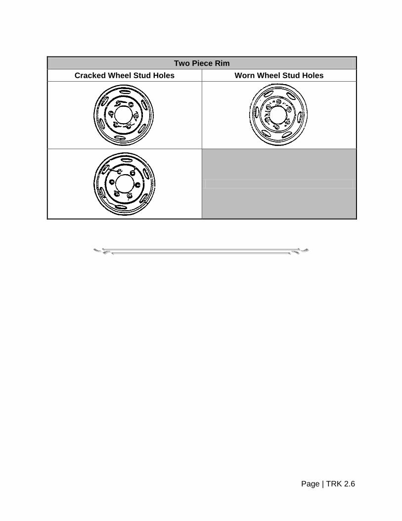
Two Piece Rim
Cracked Wheel Stud Holes Worn Wheel Stud Holes
Page | TRK 2.6


SECTION 3 – STEERING MECHANISM AND SUSPENSION
The steering system of the vehicle must be inspected to determine if excessive wear and/or maladjustment of the linkage and/or steering gear exists. Vehicles equipped with power steering must have the engine running, with fluid level and belt tension adequate before testing. The suspension system must be inspected to determine if excessive wear, cracks or breakage exists which would prevent securement of the vehicle's axles to the vehicle frame.
STEERING MECHANISM Procedure: 1. Inspect steering wheel. Reject vehicle if: Steering wheel not properly secured. 2. Inspect steering lash equipment needed: rule or tape measure, chalk or marker. Reject vehicle if:
Steering Wheel Diameter
Manual Steering System
Power Steering System
16" or less 2" + 4½" + 18" 2¼" + 4¾" + 20" 2½" + 5¼" + 22" 2¾" + 5¾” +
For power steering, if steering wheel movement exceeds forty-five degrees (45°) before steering axle tires move, proceed as follows: Rock steering wheel left to right between points of power steering valve resistance. If that motion exceeds thirty degrees (30°), or the inch movement values shown for manual steering, vehicle shall be rejected.
Page | TRK 3.1

3. Inspect steering column. Reject vehicle if: a. Any absence or looseness of U-bolts or positioning parts. b. Worn faulty or obvious repair; welded universal joints. 4. Inspect front axle beam. Reject vehicle if:
a. Any cracks. b. Any obvious welded repair(s).
5. Inspect steering gear box. Reject vehicle if:
a. Any mounting bolt(s) loose or missing.
b. Any cracks in gearbox or mounting brackets. 6. Inspect pitman arm. Reject vehicle if: Any looseness of the pitman arm or the steering gear output shaft. 7. Inspect power steering. Reject vehicle if: a. Auxiliary power assist cylinder loose. b. Power steering fluid is leaking or dripping from any point in the system and fluid
in the reservoir is below the proper operating level. 8. Inspect ball and socket joints. Reject vehicle if: a. Any movement under steering load of a stud nut.
Page | TRK 3.2

b. Any motion, other than rotational, between any linkage member and its attachment point of more than one-quarter of an inch (¼”).
9. Inspect tie rod and drag links. Reject vehicle if:
a. Loose clamp(s) or clamp bolt(s) on tie rods or drag links. b. Any looseness in any threaded joint.
10. Inspect nuts. Reject vehicle if: Loose or missing nuts on tie rods, pitman arm, drag link, steering arm or tie rod arm. 11. Inspect steering system. Reject vehicle if:
Any modification or other condition that interferes with free movement of any steering component.
Page | TRK 3.3

HEAVY TRUCK STEERING SYSTEM
12. Inspect kingpin. Procedure: a. Grasp top and bottom of tire (or use pry bar) and attempt to rock in and out to
determine king pin looseness as in the diagram below. b. Measure the movement at top or bottom of tire at the outer circumference using a
dial indicator.
Page | TRK 3.4
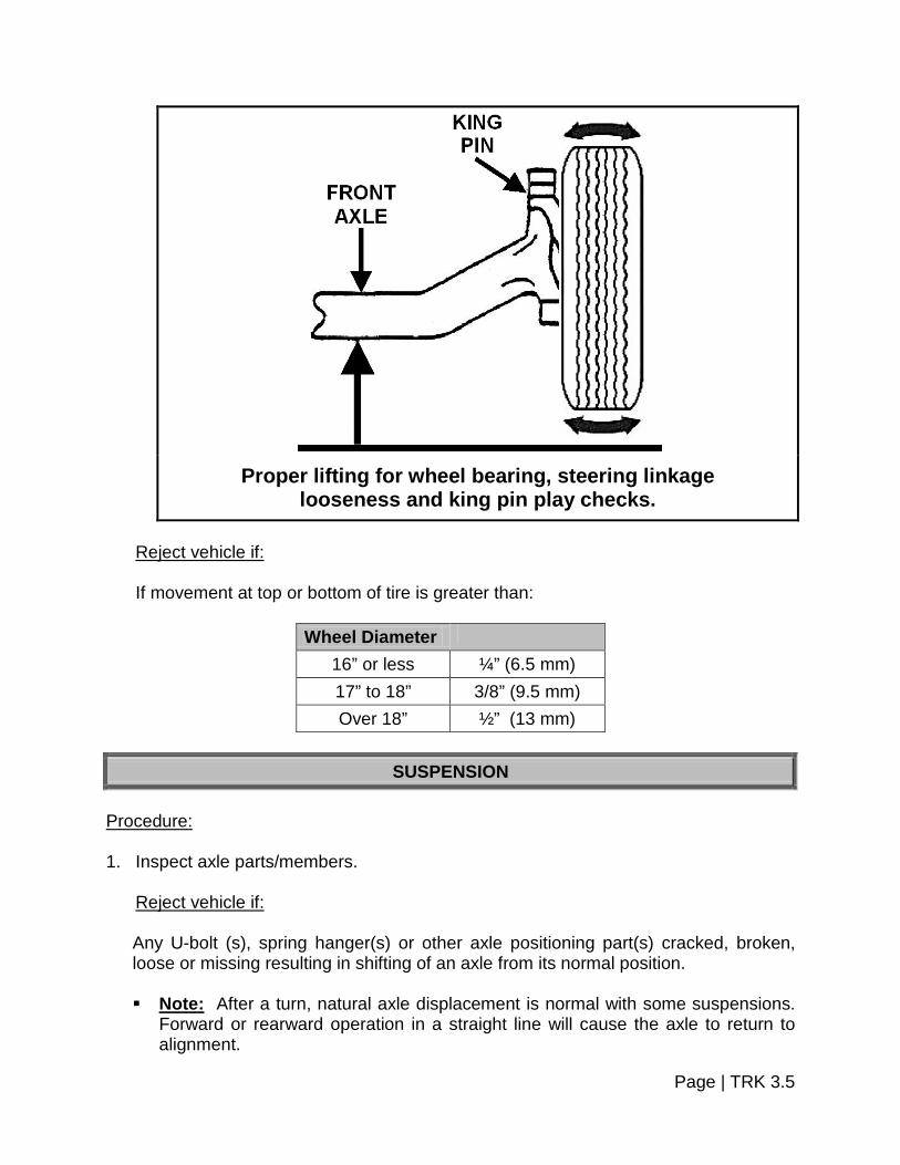
Proper lifting for wheel bearing, steering linkage
looseness and king pin play checks. Reject vehicle if: If movement at top or bottom of tire is greater than:
Wheel Diameter
16” or less ¼” (6.5 mm) 17” to 18” 3/8” (9.5 mm) Over 18” ½” (13 mm)
SUSPENSION
Procedure: 1. Inspect axle parts/members. Reject vehicle if:
Any U-bolt (s), spring hanger(s) or other axle positioning part(s) cracked, broken, loose or missing resulting in shifting of an axle from its normal position. Note: After a turn, natural axle displacement is normal with some suspensions.
Forward or rearward operation in a straight line will cause the axle to return to alignment.
Page | TRK 3.5

2. Inspect spring assembly. Reject vehicle if:
a. Any leaves in any leaf spring assembly broken or missing.
b. Any broken main leaf in a leaf spring.
c. Coil spring broken.
d. Rubber spring missing.
e. One (1) or more leaves displaced in a manner that could result in contact with a tire, rim, brake drum or frame.
f. Broken torsion bar spring in torsion bar suspension.
g. Deflated air suspension; i.e., system failure, leak, etc.
h. Spring shackles, pins and bushings are worn to a point where spring shackles
contact frame. 3. Inspect torque, radius or tracking components. Reject vehicle if: Any part of a torque, radius or tracking component assembly or any part used for
attaching same to the vehicle frame or axle is cracked, loose, broken or missing (including missing bushings, but not loose bushings in torque or track rods).
Page | TRK 3.6

HYME JOINTS – CONTROL ARM ASSEMBLIES The design of some upper and/or lower control arm assemblies consists of an inner steel sleeve mounted in a rubber bushing on one end of an adjustable or non-adjustable shaft and a ball joint on the other end of the shaft. The bushing style end of the control arm is sometimes referred to as a “Hyme Joint”.
Equipment:
Floor jack or lift, rule or gauge.
Page | TRK 3.7

Procedure: 1. With vehicle lifted properly grasp tire at top and bottom, rock in and out and record
movement. There should be no movement or play in the Hyme Joint part of the control arm assembly.
2. Consult manufacturer accepted tolerance for ball joint wear. Caution: If air suspension vehicles are lifted via body support area, air spring
damage may occur if the air suspension switch is not turned off. Reject vehicle if: 1. There is any play in the Hyme Joint, or the ball joint wear
exceeds manufacturer limits. 2. Control arm is severely rusted to a point where its integrity
is compromised. Illustrated is a typical control arm assembly, made up of a ball joint and Hyme Joint connected by an adjustable shaft. Check for deterioration of the rubber which bonds the inner bushing to the control arm on the Hyme Joint. If there is zero play in the joint but the rubber bushing is severely deteriorated consider changing the assembly.
Page | TRK 3.8


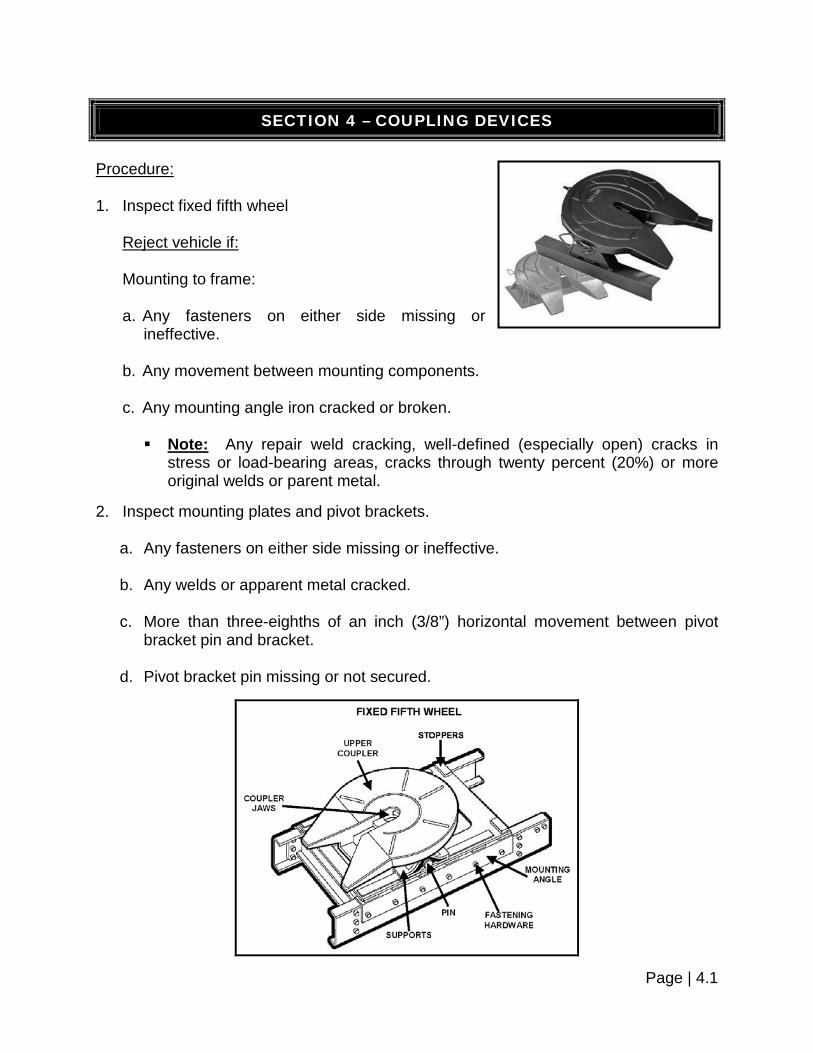
SECTION 4 – COUPLING DEVICES
Procedure: 1. Inspect fixed fifth wheel Reject vehicle if: Mounting to frame: a. Any fasteners on either side missing or
ineffective. b. Any movement between mounting components. c. Any mounting angle iron cracked or broken.
Note: Any repair weld cracking, well-defined (especially open) cracks in stress or load-bearing areas, cracks through twenty percent (20%) or more original welds or parent metal.
2. Inspect mounting plates and pivot brackets.
a. Any fasteners on either side missing or ineffective.
b. Any welds or apparent metal cracked.
c. More than three-eighths of an inch (3/8”) horizontal movement between pivot bracket pin and bracket.
d. Pivot bracket pin missing or not secured.
Page | 4.1

3. Inspect sliding fifth wheel. Reject vehicle if:
a. Any latching fasteners missing or ineffective.
b. Any fore or aft stop missing or not securely attached.
c. Movement of more than three-eighths of an inch
(3/8”) between slider bracket and slider base.
d. Any slider component cracked in parent metal or weld.
4. Inspect lower coupler. Reject vehicle if:
a. Horizontal movement between the upper and lower fifth wheel halves exceed one-half of an inch (½”).
b. Operating handle not in closed or locked position.
c. Kingpin not properly engaged.
d. Separation between upper and lower coupler allowing light to show through from
side to side.
e. Cracks in fifth wheel plate.
Page | 4.2

Exceptions: (1) Cracks in fifth wheel approach ramps, and
(2) Casting shrinkage cracks in the ribs of the body of a cast fifth wheel.
f. Locking mechanism parts missing, broken or deformed to the extent the kingpin
is not securely held. 5. Inspect pintle hooks. Equipment: Tape measure or micrometer. Reject vehicle if: a. Inspect mounting to frame.
(1) Any missing or ineffective fasteners.
Note: A fastener is not considered missing if there is an empty hole in the device but no corresponding hole in the frame and vice versa.
(2) Mounting surface cracks extending from points of attachment.
(3) Loose mounting.
(4) Frame cross-member providing pintle hook attachment not secured or cracked.
b. Inspect integrity of pintle hook.
(1) Any cracks in pintle hook assembly.
(2) Section reduction visible when coupled.
Note: No part of the eye should have any section reduced by more than twenty percent (20%). If wear can be seen when the hook and eye are coupled, it is probable that either this condition or that wear in the drawbar eye exists.
(3) Latch insecure.
(4) Any welded repairs to the pintle hook. c. Pintle hook does not pivot as designed.
Page | 4.3

PINTLE HOOKS
Pintle hooks are attached to the TOWING vehicle. They hook onto some type of drawbar on the TOWED vehicle with a locking latch that closes over the pintle eye to prevent detachment. The mounting of the pintle hook must be reinforced as it carries a tremendous amount of weight.
TYPES OF PINTLE HOOKS
AIR RIGID
SPRING SWIVEL
Page | 4.4


SECTION 5 – LIGHTING AND ELECTRICAL SYSTEMS
Preparation for headlamp and aim inspection to be done by owner of vehicle prior to inspection. Equipment: Mechanical aimer or screen. (Refer to Section 5 of the Pleasure Car and Light Truck Section for details.) Procedure: 1. Inspect headlight adjustment. (Refer to “Headlamp Aiming Information” in Section 5
of the Pleasure Car and Light Truck Section.) Reject vehicle: Vehicle does not meet the following high beam and low beam minimum limits:
a. If horizontal aim is more than:
4” to the left, or
4” to the right
b. If vertical aim is:
Higher than 4” up, or
Lower than 4” down 2. Inspect all other lamps for missing, inoperative, improper color, insecure mounting or
poor electrical connection. Reject vehicle if:
At anytime, day or night:
a. Does not have at least one (1) operative stop lamp on the rear of a single unit vehicle or the rearmost vehicle of a combination of vehicles (if equipped with two [2], both must work).
b. Does not have operative turn signal on each side of the rear of a single unit
vehicle or the rearmost vehicle of a combination of vehicles.
Page | TRK 5.1
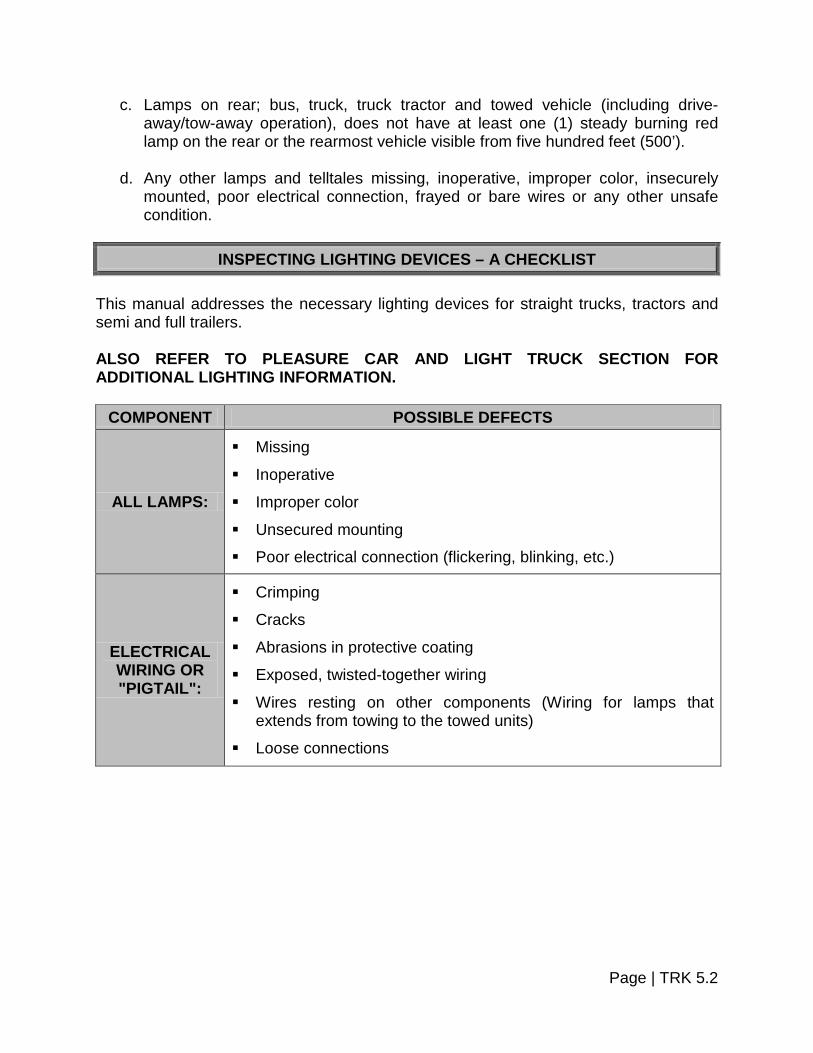
c. Lamps on rear; bus, truck, truck tractor and towed vehicle (including drive-away/tow-away operation), does not have at least one (1) steady burning red lamp on the rear or the rearmost vehicle visible from five hundred feet (500’).
d. Any other lamps and telltales missing, inoperative, improper color, insecurely
mounted, poor electrical connection, frayed or bare wires or any other unsafe condition.
INSPECTING LIGHTING DEVICES – A CHECKLIST
This manual addresses the necessary lighting devices for straight trucks, tractors and semi and full trailers. ALSO REFER TO PLEASURE CAR AND LIGHT TRUCK SECTION FOR ADDITIONAL LIGHTING INFORMATION.
COMPONENT POSSIBLE DEFECTS
ALL LAMPS:
Missing
Inoperative
Improper color Unsecured mounting Poor electrical connection (flickering, blinking, etc.)
ELECTRICAL WIRING OR "PIGTAIL":
Crimping
Cracks
Abrasions in protective coating
Exposed, twisted-together wiring
Wires resting on other components (Wiring for lamps that extends from towing to the towed units)
Loose connections
Page | TRK 5.2

STRAIGHT TRUCKS
STRAIGHT TRUCK FRONT:
At least two (2) headlamps, an equal number on each side (white)
Two (2) turn signals, one (1) on each side (white or amber)
Two (2) emergency flashers usually combined with turn signals Two (2) clearance lamps (amber) Three (3) identification lamps (amber)
Page | TRK 5.3

STRAIGHT TRUCKS
STRAIGHT TRUCK REAR:
Two (2) tail lamps, one (1) on each side (red)
Two (2) stop lamps, one (1) on each side (red)
Two (2) turn signals, one (1) at each side (red, yellow or amber)
Two (2) emergency flashers, usually combined with turn signals Two (2) clearance lamps (red) Three (3) identification lamps (red)
Page | TRK 5.4
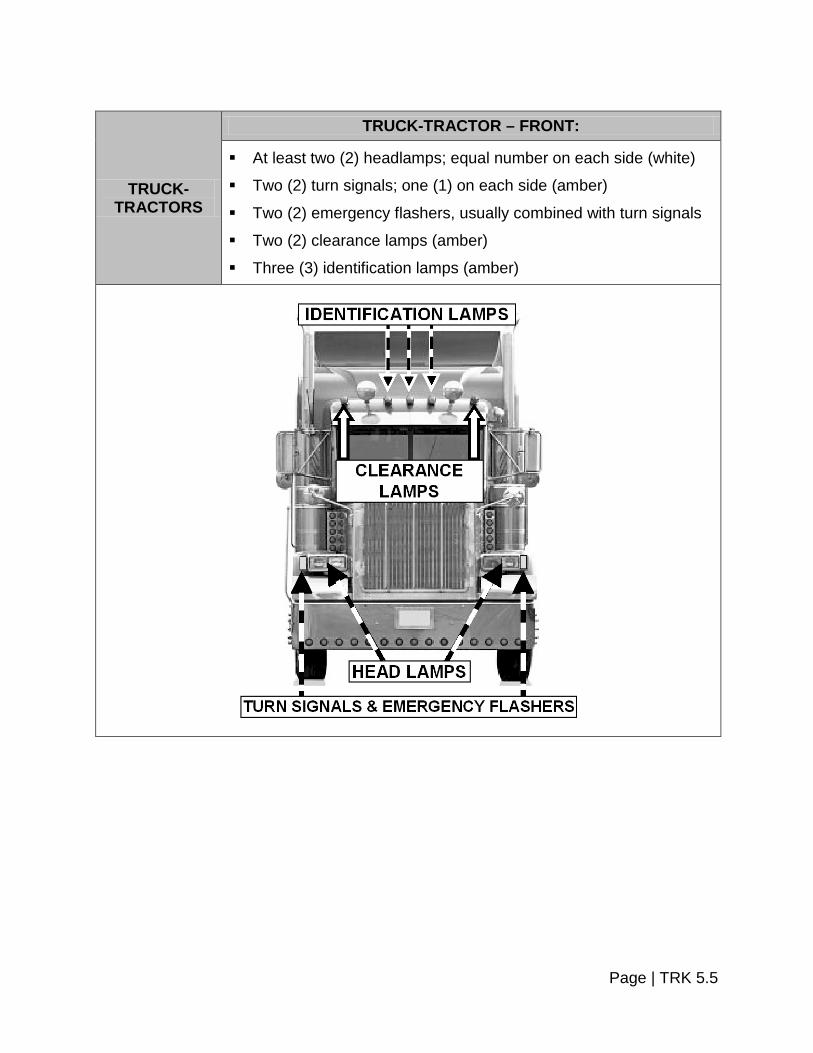
TRUCK- TRACTORS
TRUCK-TRACTOR – FRONT:
At least two (2) headlamps; equal number on each side (white)
Two (2) turn signals; one (1) on each side (amber)
Two (2) emergency flashers, usually combined with turn signals Two (2) clearance lamps (amber) Three (3) identification lamps (amber)
Page | TRK 5.5

TRUCK- TRACTORS
TRUCK-TRACTOR – REAR:
One (1) tail lamp minimum on back of frame (red)
One (1) stop lamp minimum on back of frame (red)
Unless the turn signals on the front are double-faced and visible to passing drivers, two (2) turn signals on the rear of the cab, one (1) at each side (red, yellow or amber)
Two (2) emergency flashers usually combined with turn signals
Page | TRK 5.6

REQUIRED VEHICLE LIGHTING EQUIPMENT
Item on the vehicle Qty. Color Location Position
Height above road in inches from the center
of the lamp
Required Devices by
Vehicle Type
Headlamps 2 White at least Front
On the front at the same height an equal number at each side of the
vertical centerline as far apart as
practicable.
Not less than 22 nor more
than 54. A, B, C
Turn signal (front): See Footnotes #2 & #12
2 Amber At or near front
One (1) on each side of the vertical centerline at the
same height as far apart as
practicable.
Not less than 15 nor more
than 83. A, B, C
Identification lamp front:
See Footnote #1
3 Amber Front
Mounted on the vertical centerline of the vehicle or
the vertical centerline of the
cab where different from the centerline
of the vehicle.
All three (3) on the same level as close as practicable to the top of the vehicle with lamp centers
spaced not less than six inches (6”) or
more than twelve inches (12”) apart.
B, C
Tail Lamp: See Footnotes
#5 & #11 2 Red Rear
One (1) lamp each side of the vertical centerline at the same height and as far apart as
practicable.
Both on the same level between 15
and 72.
A, B, C, D, E, F, G, H
Stop Lamp: See Footnotes
#5 & #13 2 Red Rear
One (1) lamp each side of the vertical centerline at the same height and as far apart as
practicable.
Both on the same level between 15
and 72.
A, B, C, D, E, F, G, H
Page | TRK 5.7

REQUIRED VEHICLE LIGHTING EQUIPMENT
Item on the vehicle Qty. Color Location Position
Height above road in inches from the center
of the lamp
Required Devices by
Vehicle Type
Clearance Lamps: See
Footnotes #9, #10 & #11
2 Amber
One (1) on each side of front
One (1) on each side of the vertical
centerline to indicate overall
width.
Both on same level as high
as practicable.
B, C, D, G, H
2 Red
One (1) on each side of
rear
One (1) on each side of the vertical
centerline to indicate overall
width.
Both on same level as high as
practicable.
B, D, G, H
Side Marker Lamp
Intermediate 2 Amber
One (1) on each
side
At or near midpoint between front and rear side marker
lamps, if over thirty feet (30’) in length.
Not less than 15.
A, B, D, F, G
Reflex Reflector
Intermediate (side)
2 Amber One (1) on each
side
At or near midpoint between front and rear side reflectors
if over thirty feet (30’) in length.
Between 15 and 60.
A, B, D, F, G
Reflex Reflector
(rear): See Footnotes #5,
#6, & #8
2 Red Rear
One (1) on each side of vertical
centerline, as far apart as
practicable.
Both on same level between
15 and 60.
A, B, C, D, E, F, G
Reflex Reflector (Rear
Side): See Footnote #4
2 Red One (1) on each side rear
As far to the rear as practicable.
Both on same level between
15 and 60.
A, B, D, F, G
Reflex Reflector
(front side) 2 Amber
One (1) on each side front
As far to the front as practicable.
Between 15 and 60.
A, B, C, D, F, G
License plate lamp (rear):
See Footnote #11
1 White At rear plate
To illuminate the license plate from the top or sides.
No requirements. A, B, C
Side Marker Lamp (front) 2 Amber
One (1) on each
side
As far to the front as practicable.
Not less than 15.
A, B, C, D, F
Page | TRK 5.8

REQUIRED VEHICLE LIGHTING EQUIPMENT
Item on the vehicle Qty. Color Location Position
Height above road in inches from the center
of the lamp
Required Devices by
Vehicle Type
Side Marker Lamp (rear): See Footnote
#11
2 Red One (1) on each
side
As far to the rear as practicable.
Not less than 15 and on the rear of trailer, not more than
60.
A, B, D, F, G
Turn signal (rear): See Footnotes #5 & #12
2 Amber or Red Rear
One (1) on each side of vertical
centerline, as far apart as
practicable.
Both on the same level between 15
and 83.
A, B, C, D, E, F, G
Identification lamp (rear):
See Footnotes #3, #7 & #15
3 Red Rear
One (1) as close as practicable to
vertical centerline. One (1) on each side with lamp
centers spaced not less than six inches
(6”) or more than twelve inches (12”)
apart.
All three (3) on same level
as close as practicable to the top of the
vehicle.
B, D, G
Vehicle Hazard Warning Flashing
Lamps: See Footnote #12
2 Amber or Red Rear N/A N/A N/A
Backup Lamp: See Footnote
#14 1 White Rear Rear No
requirements. A, B, C
Parking Lamp 2 Amber
or White
Front
One (1) on each side of vertical
centerline, as far apart as
practicable.
Both on same level between
15 and 72. A
*Lighting requirements per Type of Commercial Vehicle as Shown in Last Column of Table: A – Small buses and trucks less than eighty inches (80”) in overall width. B – Buses and trucks eighty inches (80”) or more in overall width. C – Truck-Tractors.
Page | TRK 5.9

D – Large semi-trailers and full trailers eighty inches (80”) or more in overall width except converter dollies.
E – Converter dolly. F – Small semi-trailers and full trailers less than eighty inches (80”) in overall width. G – Pole trailers. H – Projecting loads. Lamps and reflectors may be combined as permitted by Paragraphs 393.22 and 4.4 of 49 – CFR 571.108, Equipment Combinations. FOOTNOTE 1:
Identification lamps may be mounted on the vertical centerline of the cab where different from the centerline of the vehicle, except where the cab is not more than forty-two inches (42”) wide at the front roof- line, then a single lamp at the center of the cab shall be deemed to comply with the requirements for identification lamps. No part of the identification lamps or their mountings may extend below the top of the vehicle windshield.
FOOTNOTE 2:
Unless the turn signals on the front are so constructed (double-faced) and located as to be visible to passing drivers, two (2) turn signals are required on the rear of the truck tractor, one (1) at each side as far apart as practicable.
FOOTNOTE 3:
The identification lamps need not be visible or lighted if obscured by a vehicle in the same combination.
FOOTNOTE 4:
Any semi-trailer or full trailer vehicles manufactured on and after March 1, 1979, shall be equipped with rear side-marker lamps at a height of not less than fifteen inches (15”) (381 mm) nor more than sixty inches (60”) (1524 mm) above the road surface, as measured from the center of the lamp on the vehicle at curb weight. The rear side marker lamps shall be visible in the vehicle's rear-view mirrors when the trailer is tracking straight.
FOOTNOTE 5:
For purposes of these regulations, each converter dolly shall be equipped with one (1) stop lamp, one (1) tail lamp, and two (2) reflectors on the rear at each side when towed singly by another vehicle. Each converter dolly shall be equipped with turn
Page | TRK 5.10

signals at the rear if the converter dolly obscures the turn signals at the rear of the towing vehicle when towed singly by another vehicle.
FOOTNOTE 6:
Pole trailers will have two (2) reflectors, one (1) on each side, placed to indicate extreme width of the trailer.
FOOTNOTE 7:
Pole trailers may have three (3) identification lamps mounted on the vertical centerline of the rear of the cab of the truck tractor drawing the pole trailer, and higher than the load being transported, in lieu of the three (3) identification lamps mounted on the rear vertical centerline of the trailer.
FOOTNOTE 8:
Pole trailers shall have on the rearmost support of the load, one (1) combination marker lamp or two (2) single lamps showing amber to the front and red to the rear and side, mounted on each side to indicate maximum width of the pole trailer, and one (1) red reflector on each side of the rearmost support for the load.
FOOTNOTE 9:
Any motor vehicle transporting a load which extends more than four inches (4”) beyond the width or the motor vehicle, or having projections beyond the rear of such vehicles, shall be equipped with the following lamps in addition to other required lamps, have the loads marked with red flags, twelve inches (12”) square. Loads projecting more than four inches (4”) beyond sides of motor vehicles:
(1) The foremost edge of the projecting load at its outermost extremity shall be
marked with an amber lamp visible from the front and both sides.
(2) The rearmost edge of the projecting load at its outermost extremity shall be marked with a red lamp visible from the rear and side.
(3) If any portion of the projecting load extends beyond both the foremost and
rearmost edge, it shall be marked with an amber lamp visible from the front, both sides, and rear.
(4) If the projecting load does not measure more than two feet (2’) from front to rear,
it shall be marked with an amber lamp visible from the front, both sides, and rear, except that if the projection is located at or near the rear it shall be marked by a red lamp visible from front, side, and rear.
Page | TRK 5.11
FOOTNOTE 10:
Projections beyond rear of motor vehicles. Motor vehicles transporting loads which extend more than four feet (4’) beyond the rear of the motor vehicle, or which have these tail boards or tailgates extending more than four feet (4’) beyond the body, shall have projections marked as follows: (1) On each side of the projecting load, one (1) red lamp, visible from the side,
located so as to indicate maximum overhang. (2) On the rear of the projecting load, two (2) red lamps, visible from the rear, one (1)
at each side and two (2) red reflectors visible from the rear, one (1) at each side, located so as to indicate maximum width.
FOOTNOTE 11:
To be illuminated when tractor headlamps are illuminated. FOOTNOTE 12:
Every bus, truck, and truck tractor shall be equipped with a signaling system that, in addition to signaling turning movements, shall have a switch or combination of switches that will cause the two (2) front turn signals and the two (2) rear signals to flash simultaneously as a vehicular traffic signal warning. The system shall be capable of flashing simultaneously with the ignition of the vehicle on or off.
FOOTNOTE 13:
To be actuated upon application of service brakes. FOOTNOTE 14:
Backup lamp (and alarm if so equipped) are required to operate when bus, truck or truck tractor is in reverse.
FOOTNOTE 15:
When the rear identification lamps are mounted at the extreme height of a vehicle, rear clearance lamps need not meet the requirement that they be located as close as practicable to the top of the vehicle.
Page | TRK 5.12

SECTION 6 – VEHICLE GLAZING (GLASS)
PROPER MARKINGS
Procedure: Inspect glass for proper markings. (Refer to Section 6 of the Pleasure Car and Light Truck Section for detailed information.) Reject vehicle if: 1. Improper or unmarked glazing materials are used for specific positions. 2. Non-transparent materials such as plywood, plastic sheathing or similar materials
are used to replace glass.
LEFT FRONT WINDOW Procedure: 1. Inspect operation of window at driver's left. 2. Window must open readily even though the vehicle has approved and operating turn
signals. Reject vehicle if: Window at driver's left cannot be readily opened to permit arm signals.
STICKERS – TINTING Procedure: Inspect all glass for unauthorized material or conditions that obscure driver's vision. Reject vehicle if: 1. Glazed surfaces contain any stickers not permitted by law or regulation.
2. Unauthorized tinting material has been used. Any after-market tinting material
sprayed, pasted, stuck or otherwise applied to the windshield or windows directly to the right or left of the driver.
Page | TRK 6.1

NOTE: The rear side windows and the back window only may be obstructed,
provided the motor vehicle is equipped on each side with a rear-view mirror. All periodic inspection stickers shall be placed on the inside top center of the windshield. If the windshield is tinted, the inspection sticker shall be centered on the windshield just below the tint edge. On divided windshields, the inspection sticker shall be placed at the top of the windshield, just to the right of the divider strip. If rear-view mirror contains a camera or sensor, the sticker shall be affixed to the right of the device.
WINDOW TINTING EXEMPTION 23 VSA 1125(a)(6) provides an exemption for any person who must be shielded from direct sunlight for medical reasons. The person may be either the driver or a regular passenger in the vehicle. A permit for such an exemption shall be issued by the Department of Motor Vehicles for either a four (4) year term (for temporary conditions) or indefinitely for a condition, which is permanent and stable. This permit must be kept in the primary vehicle listed and a copy of it must be housed in each subsequently exempted vehicle. The affected vehicles will be listed on the permit. The provisions of the permit terminate upon the sale or transfer of the approved vehicle(s) and at that time, the seller must remove the applicable tinting. Furthermore, if the approved window tinting tears or bubbles or is otherwise worn to prohibit clear vision, it must be removed. Procedure: 1. For a vehicle with a window tinting exemption, examine the tinting applied and check
for tears, bubbles or any other defect in its application, which could in any way prohibit clear vision.
2. Inspect the window-tinting permit, which should be available for inspection along with the vehicle’s registration and insurance documents. Check the permit’s expiration date to make sure it is valid. Confirm the vehicle being inspected matches the vehicle listed on the permit for the tinting exemption.
3. Examine the window tinting exemption sticker affixed to the vehicle’s windshield,
adjacent to the inspection sticker. Ensure the sticker is valid by checking it’s expiration date with the expiration date listed on the permit.
Reject vehicle if: 1. The window tinting permitted by the exemption permit is torn, bubbled or is
otherwise worn or applied in a way in which clear vision is prohibited.
2. The window tinting medical exemption permit is not available for inspection.
Page | TRK 6.2
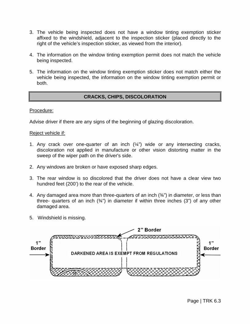
3. The vehicle being inspected does not have a window tinting exemption sticker affixed to the windshield, adjacent to the inspection sticker (placed directly to the right of the vehicle’s inspection sticker, as viewed from the interior).
4. The information on the window tinting exemption permit does not match the vehicle
being inspected. 5. The information on the window tinting exemption sticker does not match either the
vehicle being inspected, the information on the window tinting exemption permit or both.
CRACKS, CHIPS, DISCOLORATION
Procedure: Advise driver if there are any signs of the beginning of glazing discoloration. Reject vehicle if: 1. Any crack over one-quarter of an inch (¼”) wide or any intersecting cracks,
discoloration not applied in manufacture or other vision distorting matter in the sweep of the wiper path on the driver's side.
2. Any windows are broken or have exposed sharp edges. 3. The rear window is so discolored that the driver does not have a clear view two
hundred feet (200’) to the rear of the vehicle. 4. Any damaged area more than three-quarters of an inch (¾”) in diameter, or less than
three- quarters of an inch (¾”) in diameter if within three inches (3”) of any other damaged area.
5. Windshield is missing.
Page | TRK 6.3


SECTION 7 – BRAKE SYSTEMS
ROAD TEST – PERFORMANCE ABILITY OF BRAKES
Brakes should perform as outlined in 23 VSA §1308, which is described below: Procedure: 1. The service brakes upon any motor truck, truck, and tractor or combination of
vehicles shall be adequate to stop such vehicle or vehicles when traveling 20 MPH within a distance of 30 feet when upon dry asphalt or concrete pavement surface free from loose material where the grade does not exceed one percent.
2. Under the above conditions, the hand brake shall be adequate to hold such vehicle
or vehicles stationary on any grade upon which it is operated. 3. All braking distances specified in this section shall apply to all vehicles mentioned,
whether such vehicles are not loaded or are loaded to the maximum capacity permitted.
4. All brakes shall be maintained in good working order and shall be so adjusted as to
operate as equally as practicable with respect to the wheels on opposite sides of the vehicle.
Reject vehicle if: Brakes do not meet any of the above requirements.
Page | TRK 7.1

THE "S" CAM BRAKE
Uses an "S" shaped cam to expand the brake shoes against the drum.
Page | TRK 7.2

THE WEDGE BRAKE
Uses a wedge forced between two (2) brake shoes to expand the shoes against the drum.
Page | TRK 7.3

THE DISC BRAKE
Uses two (2) brake pads pinched against a rotating disc or rotor.
DISC BRAKE, SIDE VIEW
(This particular disc is from a hydraulic system.)
EXAMPLE DISC BRAKE (This particular disc is from an
air system.)
Page | TRK 7.4

Note: Trucks and truck-tractors having three (3) or more axles need not have brakes on front axle on vehicles manufactured prior to July 25, 1980.
HYDRAULIC BRAKES
Procedure: 1. Check master cylinder for fluid level. Reject vehicle if: Master cylinder less than one-quarter (¼) full. Note: Normally to be inspected when readily visible or problems are apparent.
2. Inspect all lines and hoses and wheel areas for visual leaks, worn brake hoses,
crimped or restricted lines. Reject vehicle if:
a. Seeping or swelling brake hose(s) under application of pressure.
b. Any visually observed leaking hydraulic fluid in the brake system.
c. Hydraulic hose(s) chafed through outer cover to fabric layer.
d. Fluid lines or connections restricted, crimped, cracked or broken. 3. Depress foot pedal and see how far it descends. Reject vehicle if:
a. Pedal descends to floor upon first application
b. No apparent pedal reserve with engine running except by pumping brake 4. Inspect vacuum assisted hydraulic system. Depress pedal hard and while holding it,
start engine. If the power unit is working, the pedal should drop appreciably under foot pressure.
Reject vehicle if: Power assist unit fails to operate.
Page | TRK 7.5

5. Inspect brake failure lamp or low brake fluid lamp.
Reject vehicle if: Lamp fails to illuminate during the indicator lamp test sequence; or if the lamp remains illuminated after the lamp test sequence has finished.
BROKEN OR UNSECURED PARTS AND LOOSE CONNECTIONS
Procedure: Visually inspect brake components at the wheels. Reject vehicle if: 1. No braking action occurs upon application of the service brakes. 2. There is missing or broken components such as shoes, linings, pads, springs,
anchor pins, spiders, cam rollers, push rods and air chamber mounting bolts. 3. Components are loose or insecurely mounted. 4. There is an audible air leak at the brake chamber. 5. Any lining or pad is not firmly attached to the shoe or is saturated with oil, grease or
brake fluid. 6. Readjustment limits are as follows: With engine off and reservoir pressure of eighty (80) to ninety (90) PSI with brakes
fully applied.
a. One (1) brake at one-quarter of an inch (¼”) or more beyond the readjustment limit. Example: Type 30 clamp type brake chamber push rod measured at two and one-quarter of an inch (2¼”) would be one (1) defective brake.
b. Two (2) brakes at the readjustment limit or less than one-quarter of an inch (¼”)
beyond the readjustment limit also equal one (1) defective brake. Example: Clamp type 30 push rods measure:
Two (2) at 2-1/8”;
One (1) at 2-1/8” and one (1) at 2”; or,
Two (2) at 2”.
Each example would equal one (1) defective brake.
Page | TRK 7.6

7. Mismatched brake chamber types/sizes are present across an axle. 8. Slack adjusters of mismatched effective lengths are present across an axle.
BRAKE LINING Procedure: 1. Visually inspect brake lining for excessive wear or missing pieces. 2. Visually inspect brake linings for saturation with oil or grease. Equipment: Measuring device. Reject vehicle if: 1. Vehicle is equipped with air brakes and lining is less than one-quarter of an inch (¼”)
thick or if lining is worn to wear indicator (if so marked) measured at the shoe center for drum brakes or less than one-eighth of an inch (1/8”) for disc brakes.
2. Vehicle is equipped with hydraulic and/or electric brakes and the lining is one-
sixteenth of an inch (1/16”) or less in thickness at the shoe center for drum brakes. 3. There is a missing brake(s) on any axle required to have brakes. 4. Any brake lining is saturated with oil or grease.
BRAKE ROTORS If the inspector obtains permission to pull the wheel(s) to more closely inspect the brake assemblies. Procedure: 1. Check rotor(s) for warping and excessive rust and corrosion.
2. Check thickness of rotor(s) with rotor thickness caliper. 3. Check for crack(s) in rotor friction surfaces.
Page | TRK 7.7

Reject vehicle if: 1. Rotor(s) thickness is less than manufacturer’s listed minimum tolerance. 2. Cooling vanes on vented rotors are corroded or rusted to the point where the rotor
collapses when pressure is applied by the brake caliper. 3. Rotor is cracked across more than 75% of the friction surface when the friction
surface is measured linearly from the inside diameter to the outside diameter.
BRAKE DRUMS Procedure: 1. Visually inspect the brake drums for cracks. 2. Check drum(s) inside diameter with proper measuring tool. Reject vehicle if: 1. The brake drums are cracked on the friction surface or the crack extends to the open
edge, or if the outside surface of drum is cracked. 2. The friction surface of the drum is contaminated with oil, grease or brake fluid. 3. Drum inside diameter exceeds manufacturer’s listed maximum tolerance. 4. Any portion of the brake drum is missing.
BRAKE COMPONENTS ON THE STEERING AXLE Procedure: Visually examine components, inspect air chambers and slack adjusters. Equipment: Measuring device. Reject vehicle if: 1. There is absence of braking action on any steering axle of any vehicle required to
have steering brakes.
Page | TRK 7.8
2. Air chamber sizes or slack adjuster length are mismatched across any power unit steering axle.
3. The lining thickness is less than three-sixteenths of an inch (3/16”) for a shoe with a
continuous strip of lining or one-quarter of an inch (¼”) for a shoe with two (2) pads for drum brakes or to wear indicator if lining is so marked, or less than one-eighth of an inch (1/8”) for air disc brakes, and one-sixteenth of an inch (1/16”) or less for hydraulic disc and electric brakes.
PARKING/HAND BRAKE
Procedure: Visually inspect parking/hand brake components for proper function. Reject vehicle if: No brakes on the vehicle or combination are applied upon activation of the parking/hand brake control, including driveline hand controlled parking/hand brake.
BRAKE HOSE AND TUBING Procedure: Visually inspect brake hose and tubing for damage, leaks and improper splicing. Reject vehicle if: 1. Hoses show any damage extending through the outer reinforcement ply. (Rubber
impregnated fabric cover is not a reinforcement ply.) (Thermoplastic nylon may have braid reinforcement or color difference between cover and inner tube. Exposure of second color is cause for rejection.)
2. Bulging or swelling occurs when air pressure is applied. 3. There is an audible leak in a hose at other than a proper connection. 4. Hose splices can be moved or separated by hand. 5. Hose splices are made by sliding the hose ends over a piece of tubing and clamping
the hose to the tube. 6. Tubing is cracked, broken or crimped.
Page | TRK 7.9
AIR SYSTEM
Procedure: 1. Inspect the complete system for improper air loss. Reject vehicle if:
An air leak is discovered and the reservoir pressure is not maintained when: a. Governor is cut in, b. Reservoir pressure is between eighty (80) and ninety (90) PSI, c. Engine is at idle and service brakes are fully applied.
2. Release sufficient air from the system to cause the low air-warning device to
activate. Reject vehicle if:
The low air warning device is missing, inoperative or does not operate at fifty five (55) PSI and below, or half (½) the governor cut out pressure, whichever is less.
3. Inspect air pressure gauge. Reject vehicle if: Gauge is missing, inoperable or does not indicate pressure in pounds per square
inch. 4. Inspect tractor protection valve(s) (vehicles in combination).
a. Release the emergency brakes by pushing in the dash valves.
b. Break the supply emergency line at the hose couplers between the tractor and the trailer. Air will leak from the tractor side of the line until the pressure in tractors system drops to the twenty (20) to forty-five (45) PSI range.
c. Depress the service brake.
Reject vehicle if: a. Valves are missing or inoperable
Page | TRK 7.10

b. Trailer brakes fail to activate properly c. A loss of air in the tractor system below the twenty (20) to forty-five (45) PSI
range indicates a malfunctioning tractor protection valve.
d. Air escapes through the service glad hand with the service brake depressed. 5. Inspect air reservoir. Reject vehicle if: Mounting bolts are broken, missing or loose (not including defective bushings). 6. Inspect air compressor. Reject vehicle if:
a. Mounting bolts are loose.
b. Pulley is loose, cracked or broken. 7. Visually inspect vacuum brake system. Reject vehicle if:
a. Vacuum reserve is insufficient to permit one (1) full brake application after engine is shut off.
b. Vacuum hose(s) or line(s) are restricted, chafed through outer cover to cord ply,
crimped, cracked, broken or has collapse of vacuum hose(s) when vacuum is applied.
c. Low vacuum warning device is missing or inoperative.
d. Vacuum gauge that indicates to the driver the vacuum in inches of mercury
available for braking is missing or inoperative.
MEASURING PUSH ROD TRAVEL Caution: Faulty brake chambers may explode, especially upon brake application.
Maintain a safe distance from chambers at all times, and never position yourself behind the chamber when the driver applies the brakes.
Page | TRK 7.11
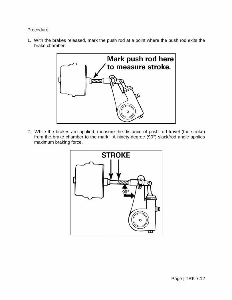
Procedure: 1. With the brakes released, mark the push rod at a point where the push rod exits the
brake chamber.
2. While the brakes are applied, measure the distance of push rod travel (the stroke)
from the brake chamber to the mark. A ninety-degree (90°) slack/rod angle applies maximum braking force.
Page | TRK 7.12
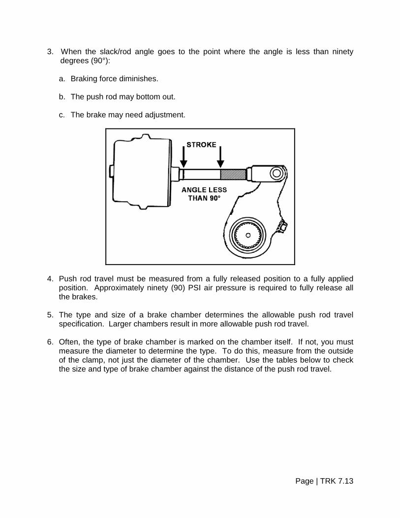
3. When the slack/rod angle goes to the point where the angle is less than ninety degrees (90°):
a. Braking force diminishes.
b. The push rod may bottom out.
c. The brake may need adjustment.
4. Push rod travel must be measured from a fully released position to a fully applied position. Approximately ninety (90) PSI air pressure is required to fully release all the brakes.
5. The type and size of a brake chamber determines the allowable push rod travel
specification. Larger chambers result in more allowable push rod travel. 6. Often, the type of brake chamber is marked on the chamber itself. If not, you must
measure the diameter to determine the type. To do this, measure from the outside of the clamp, not just the diameter of the chamber. Use the tables below to check the size and type of brake chamber against the distance of the push rod travel.
Page | TRK 7.13

ROTOCHAMBER TYPE (Diameter in Inches)
Type
Effective Area
(Square In.)
Outside diameter
Maximum stroke at which brakes should
be readjusted 9 9” 4-9/32” 1½”
12 12” 4-13/16” 1½” 16 16” 5-13/32” 1-7/8” 20 20” 5-15/16” 1-7/8” 24 24” 6-13/32” 1-7/8” 30 30” 7-1/16” 2¼” 36 36” 7-5/8” 2-5/8” 50 50” 8-7/8” 3”
“STANDARD” CLAMP TYPE BRAKE CHAMBER DATA
Type Outside Diameter
Rated Stroke
Maximum stroke at which brakes must
be readjusted 9 5-1/4” 1.75” 1-3/8” 12 5-11/16” 1.75” 1-3/8” 16 6-3/8” 2.25” 1-3/4” 20 6-25/32” 2.25” 1-3/4” 24 7-7/32” 2.25” 1-3/4” 30 8-3/32” 2.50” 2” 36* 9” 3.00” 2-1/4”
*Note: If type 36 chamber is used, slack length should be less than 6”.
“LONG STROKE” CLAMP TYPE BRAKE CHAMBER DATA
Type Outside Diameter
Rated Stroke
Maximum stroke at which brakes must
be readjusted 16 6-3/8” 2.50” 2” 20 6-25/32” 2.50” 2” 24 7-7/32” 2.50” 2” 24* 7-7/32” 3.00” 2-1/2” 30* 8-3/32” 3.00” 2-1/2”
*Note: Identified by square air port bosses. Note: Automatic brake slack adjusters are required on air brake equipped vehicles
manufactured on and after October 20, 1994. Replacing or re-adjusting a self-adjusting brake adjuster that exceeds the maximum push rod stroke does not guarantee that the defect is corrected. There may be defects in other components of the foundation brake system.
Page | TRK 7.14

INSPECTING WEDGE BRAKE ADJUSTMENT
Procedure: 1. With the inspection hole cover removed from the brake dust shield, check the
adjustment at each wheel visually or using a feeler gauge.
2. With the brakes fully released, inspect this distance from the drum to the brake shoe
(lining surface). This distance must not exceed one-sixteenth of an inch (1/16”). (If using a feeler gauge, the gap must not exceed .0625).
Page | TRK 7.15

INSPECTING LINING WITH FEELER GAUGE
If the edge of the lining is not visible, mark the lining and then apply the brakes. When the brake shoe moves, watch the mark or measure the movement with a gauging device. Any brake shoe travel beyond one-sixteenth of an inch (1/16”) (.0625) is excessive. Failure of the brake shoes to move is a condition of improper maintenance.
CROSS SECTION OF WEDGE BRAKE MEASUREMENT Brake shoe contact or non-contact is also indicated by striking the drum with a metal tool. The drum will echo or ring if the shoes are not contacting; if the shoes are contacting the drum, a dull sound will result.
ANTILOCK BRAKE SYSTEM Procedure: Inspect antilock brake system in accordance with the ABS Inspection Procedure. Reject vehicle if: ABS, including the ABS malfunction lamp, does not function in accordance with the ABS Inspection Procedure.
Page | TRK 7.16
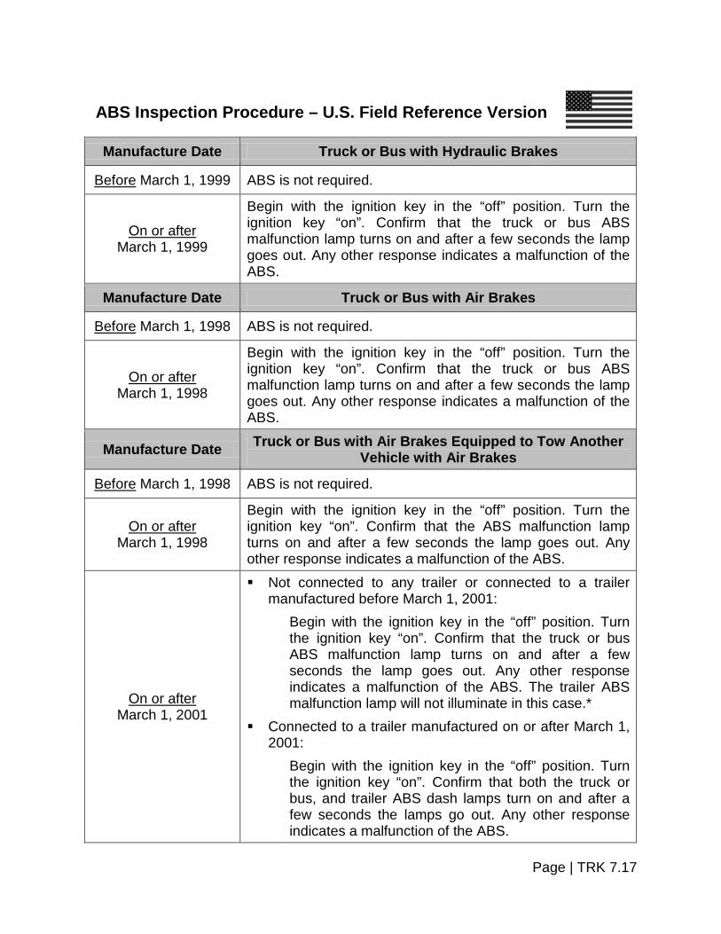
ABS Inspection Procedure – U.S. Field Reference Version
Manufacture Date Truck or Bus with Hydraulic Brakes
Before March 1, 1999 ABS is not required.
On or after March 1, 1999
Begin with the ignition key in the “off” position. Turn the ignition key “on”. Confirm that the truck or bus ABS malfunction lamp turns on and after a few seconds the lamp goes out. Any other response indicates a malfunction of the ABS.
Manufacture Date Truck or Bus with Air Brakes
Before March 1, 1998 ABS is not required.
On or after March 1, 1998
Begin with the ignition key in the “off” position. Turn the ignition key “on”. Confirm that the truck or bus ABS malfunction lamp turns on and after a few seconds the lamp goes out. Any other response indicates a malfunction of the ABS.
Manufacture Date Truck or Bus with Air Brakes Equipped to Tow Another Vehicle with Air Brakes
Before March 1, 1998 ABS is not required.
On or after March 1, 1998
Begin with the ignition key in the “off” position. Turn the ignition key “on”. Confirm that the ABS malfunction lamp turns on and after a few seconds the lamp goes out. Any other response indicates a malfunction of the ABS.
On or after March 1, 2001
Not connected to any trailer or connected to a trailer manufactured before March 1, 2001:
Begin with the ignition key in the “off” position. Turn the ignition key “on”. Confirm that the truck or bus ABS malfunction lamp turns on and after a few seconds the lamp goes out. Any other response indicates a malfunction of the ABS. The trailer ABS malfunction lamp will not illuminate in this case.*
Connected to a trailer manufactured on or after March 1, 2001:
Begin with the ignition key in the “off” position. Turn the ignition key “on”. Confirm that both the truck or bus, and trailer ABS dash lamps turn on and after a few seconds the lamps go out. Any other response indicates a malfunction of the ABS.
Page | TRK 7.17

Manufacture Date Truck Tractor with Air Brakes
Before March 1, 1997 ABS is not required.
On or after March 1, 1997
Begin with the ignition key in the “off” position. Turn the ignition key “on”. Confirm that the ABS malfunction lamp turns on and after a few seconds the lamp goes out. Any other response indicates a malfunction of the ABS.
On or after March 1, 2001
Not connected to any trailer or connected to a trailer manufactured before March 1, 2001:
Begin with the ignition key in the “off” position. Turn the ignition key “on”. Confirm that the tractor ABS malfunction lamp turns on and after a few seconds the lamp goes out. Any other response indicates a malfunction of the ABS. The trailer ABS malfunction lamp will not illuminate in this case.*
Connected to a trailer manufactured on or after March 1, 2001:
Begin with the ignition key in the “off” position. Turn the ignition key “on”. Confirm that both tractor and trailer dash-mounted ABS malfunction lamps turn on and after a few seconds the lamps go out. Any other response indicates a malfunction of the ABS.
Manufacture Date Trailer with Air Brakes (Including a Trailer Converter Dolly)
Before March 1, 1998 ABS is not required.
On or after March 1, 1998
Connected to a truck or truck tractor manufactured before March 1, 1997.
Apply the brake pedal and confirm that the trailer-mounted ABS malfunction lamp turns on and after a few seconds goes out before the brake is released. Any other response indicates a malfunction of the ABS.
Connected to a truck or truck tractor manufactured on or after March 1, 1997. **
Begin with the ignition key in the “off” position. Turn the ignition key “on”. Confirm that the trailer-mounted ABS malfunction lamp turns on and after a few seconds the lamp goes out. Any other response indicates a malfunction of the ABS.
Page | TRK 7.18

Manufacture Date Continued – Trailer with Air Brakes (Including a Trailer Converter Dolly)
On or after March 1, 2001
Connected to a truck or truck tractor manufactured before March 1, 2001.
Test in the same manner as trailers manufactured on or after March 1, 1998.
Connected to a truck or truck tractor manufactured on or after March 1, 2001.
Begin with the ignition key in the “off” position. Turn the ignition key “on”. Confirm that both the trailer dash-mounted ABS malfunction lamp and the trailer-mounted ABS malfunction lamp turn on and after a few seconds the lamps go out. Any other response indicates a malfunction of the ABS.
* The trailer ABS lamp in the dash only operates when the tractor is connected to a trailer manufactured after March 1, 2001.
** Power to the trailer’s ABS circuit is delivered by a dedicated circuit from the truck
tractor. In the U.S. the following vehicles are exempt from the requirements to have ABS: Any trailer that has a width of more than 102.36 inches with extendable equipment in
the fully retracted position and is equipped with two short track axles in a line across the width of the trailer.
Any vehicle equipped with an axle that has a gross axle weight rating (GAWR) of
29,000 pounds or more. Any truck or bus that has a speed attainable in 2 miles of not more than 33 MPH. Any truck that has a speed attainable in 2 miles of not more than 45 MPH, an
unloaded vehicle weight that is not less than 95 percent of its gross vehicle weight rating (GVWR), and no capacity to carry occupants other than the driver and operating crew.
Any trailer that has a GVWR of more than 120,000 pounds and whose body
conforms to that described in the definition of heavy hauler trailer set forth in S4 of the Federal Motor Carrier Safety Administration regulations; Heavy hauler trailer means a trailer which has one or more of the following characteristics, but which is not a container chassis trailer:
Page | TRK 7.19

Its brake lines are designed to adapt to separation or extension of the vehicle frame, or
Its body consists only of a platform whose primary cargo-carrying surface is not
more than 40 inches above the ground in an unloaded condition, except that it may include sides that are designed to be easily removable and a permanent "front end structure" as that term is used in §393.106 of the Federal Motor Carrier Safety Administration regulations.
Any trailer that has an unloaded vehicle weight which is not less than 95 percent of
its GVWR. Any load divider dolly.
Page | TRK 7.20


SECTION 8 – FUEL SYSTEM
Procedure: Visually inspect fuel tanks, fuel lines and mounting hardware including tanks, lines and mounting hardware for refrigeration or heating units. Reject vehicle if: 1. The fuel system has a visible leak at any point. 2. Tank(s) not securely attached to the motor vehicle by reason of loose, broken or
missing mounting bolts or brackets. 3. Fuel tank filler cap is loose or missing. 4. The fuel tank(s) extend outside the perimeter of the vehicle. 5. Fuel lines are routed so that damage to them is likely to occur. 6. Fill pipe is located so that fuel may spill onto exhaust while filling. 7. There is no internal venting system (for tanks that can contain twenty-five (25)
gallons or more).
Page | TRK 8.1


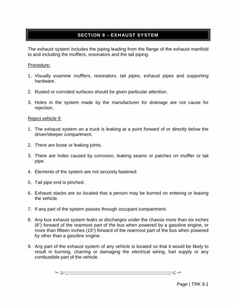
SECTION 9 – EXHAUST SYSTEM
The exhaust system includes the piping leading from the flange of the exhaust manifold to and including the mufflers, resonators and the tail piping. Procedure: 1. Visually examine mufflers, resonators, tail pipes, exhaust pipes and supporting
hardware. 2. Rusted or corroded surfaces should be given particular attention. 3. Holes in the system made by the manufacturer for drainage are not cause for
rejection. Reject vehicle if: 1. The exhaust system on a truck is leaking at a point forward of or directly below the
driver/sleeper compartment. 2. There are loose or leaking joints. 3. There are holes caused by corrosion, leaking seams or patches on muffler or tail
pipe. 4. Elements of the system are not securely fastened. 5. Tail pipe end is pinched. 6. Exhaust stacks are so located that a person may be burned on entering or leaving
the vehicle. 7. If any part of the system passes through occupant compartment. 8. Any bus exhaust system leaks or discharges under the chassis more than six inches
(6”) forward of the rearmost part of the bus when powered by a gasoline engine, or more than fifteen inches (15”) forward of the rearmost part of the bus when powered by other than a gasoline engine.
9. Any part of the exhaust system of any vehicle is located so that it would be likely to
result in burning, charring or damaging the electrical wiring, fuel supply or any combustible part of the vehicle.
Page | TRK 9.1


SECTION 10 – FLARES, FLAGS, FLAPS AND FENDERS
MUD FLAPS AND FENDERS
Equipment: Measuring Device. Procedure: 1. Inspect fenders and flaps to determine that they are solidly attached and of
substantial material, cover the full width of the tread to prevent throwing dirt, water or other material onto the windshield of vehicles following.
2. If a flap is required, the following standards will be followed:
The splash pans stone throw protection device shall extend laterally for at least the width of the tires and shall be composed of material or flexible materials substantial enough to withstand ripping or tearing by ordinary means, and also shall be long enough so that the clearance from the ground to the bottom edge of the device shall be not more than one-half (½) of the distance from the bottom edge of the device to the center line of the rearmost axle of the vehicle. However, the bottom edge of such device need be no closer to the road than six inches (6”) when loaded.
Reject vehicle if: 1. Fenders of flaps are not solidly attached. 2. Are not constructed of substantial materials. 3. Are not of sufficient size or are not attached properly. 4. Do not meet the criteria set out in the following pictures. 5. Fenders do not cover the entire tread width. 6. Come into contact with the tire or wheel.
Page | TRK 10.1

Flaps required, as the distance from rear edge of truck body to the ground is over half (½) the distance from center of rearmost axle to rear edge of body.
Flaps required, as the distance from rear edge of fender to the ground is over half (½) the distance from center of rearmost axle to rear edge of fender.
FLARES AND FLAGS
Procedure: Inspect for presence of emergency warning devices. Reject vehicle if: 1. The vehicle is not transporting hazardous materials and there is not three (3)
reflective triangles, or six (6) fuses, or three (3) liquid burning flares in the vehicle.
2. The vehicle is transporting hazardous materials and there is not three (3) reflective triangles in the vehicle.
Page | TRK 10.2


SECTION 11 – BODY AND SHEET METAL
Body components and sheet metal are subject to rejections if a condition exists which is hazardous to occupants, pedestrians or other vehicles. Most truck tractors are inspected without attached trailers, and allowance should be made for protruding exterior mirrors to include the width of a towed load when checking "unnecessary protrusion".
EXTERIOR REAR-VIEW MIRROR Procedure: 1. From the driver's position, visually inspect exterior mirror on driver's side for a clear
and reasonably unobstructed view to the rear. 2. Look for correct location, stable mounting, cracks, sharp edges, unnecessary
protrusion and ease of adjustment. 3. All motor trucks shall be equipped with a mirror not less than five inches (5”) in
diameter, or a mirror with at least sixteen (16) square inches of reflective area. Reject vehicle if: 1. Mirror not mounted on stable support. 2. Mirror protrudes an unnecessary amount beyond line offering satisfactory rear
vision. 3. Mirror obscured by a pillar or unwiped portion of windshield. 4. Mirror cracked, pitted or clouded to the extent that rear vision is obscured. 5. Mirror does not meet required size.
SPEEDOMETER AND ODOMETER/HUBOMETER Procedure: All motor vehicles, excluding trailers, semi-trailers, motorcycles, mopeds and trailer coaches must be equipped with a speedometer and odometer/hubometer so connected to the vehicle as to render both operable. The dial and calibrations on the speedometer shall be legible and unobstructed from the view of the operator of the vehicle
Page | TRK 11.1

Reject vehicle if: Speedometer and/or odometer/hubometer is not operational.
HORN Procedure: Should be securely fastened. Reject vehicle if: 1. If horn is loose. 2. Fails to function.
WINDSHIELD WIPERS Reject vehicle if: Any power unit that has an inoperative wiper or damaged parts that render it ineffective on the driver's side.
BUMPERS Refer to Section 7 of the Pleasure Car and Light Truck Section.
DEFROSTERS Refer to Section 7 of the Pleasure Car and Light Truck Section.
DOORS Refer to Section 7 of the Pleasure Car and Light Truck Section.
HOOD Refer to Section 7 of the Pleasure Car and Light Truck Section.
Page | TRK 11.2

FLOOR PAN
Refer to Section 7 of the Pleasure Car and Light Truck Section.
PROTRUDING METAL Refer to Section 7 of the Pleasure Car and Light Truck Section.
CAPS AND BED LINERS Refer to Section 7 of the Pleasure Car and Light Truck Section. SEATS, SEAT BELT ASSEMBLIES, AND SEAT BELT ASSEMBLY ANCHORAGES
1. Buses:
a. Buses manufactured on or after January 1, 1965, and before July 1, 1971. After June 30, 1972, every bus manufactured on or after January 1, 1965, and before July 1, 1971, must be equipped with a Type I or Type 2 seat belt assembly that conforms to Federal Motor Vehicle Safety Standard No. 209 (571.209) installed at the driver's seat and seat belt assembly anchorage's that conform to the location and geometric requirements of Federal Motor Vehicle Safety Standard No. 210 (571.210) for that seat belt assembly.
b. Buses manufactured on or after July 1, 1971. Every bus manufactured on or
after July 1, 1971, must conform to the requirements of Federal Motor Vehicle Safety Standard No. 208 (571.208) (relating to installation of seat belt assemblies) and Federal Motor Vehicle Safety Standard No. 210 (571.210) (relating to installation of seat belt assembly anchorage's).
c. Buses manufactured on or after January 1, 1972. Every bus manufactured on
or after January 1, 1972, must conform to the requirements of Federal Motor Vehicle Safety Standards No. 207 (571.207) (relating to seating systems).
2. Trucks and truck tractors:
a. Trucks and truck tractors manufactured on or after January 1, 1965, and before July 1, 1971. Except as provided in paragraph (d) of this Section, after June 30, 1972, every truck and truck tractor manufactured on or after January 1, l965, and before July 1, 1971, must be equipped with a Type I or Type 2 seat belt assembly that conforms to Federal Motor Vehicle Safety Standard No. 209 (571.209) installed at the driver's seat and at the right front outboard seat, if the
Page | TRK 11.3
vehicle has one, and seat belt assembly anchorage's that conform to the location and geometric requirements of Federal Motor Vehicle Safety Standards No. 210 (571.210) for each seat belt assembly that is required by this subparagraph.
b. Trucks and truck tractors manufactured on or after July 1, 1971. Every truck
and truck tractor manufactured on or after July 1, 1971, except a truck or truck tractor being transported in driveaway-towaway operation and having an incomplete vehicle seating and cab configuration, must conform to the requirements of Federal Motor Vehicle Safety Standard No. 208 (571.208) (relating to installation of seat belt assemblies) and Federal Motor Vehicle Safety Standard No. 210 (571.210) (relating to installation of seat belt assembly anchorage's).
c. Trucks and truck tractors manufactured on or after January 1, 1972. Every
truck and truck tractor manufactured on or after January 1, 1972, except a truck or truck tractor being transported in driveaway-towaway operation and having an incomplete vehicle seating and cab configuration, must conform to the requirements of Federal Motor Vehicle Safety Standard No. 207 (571.207) (relating to seating systems).
3. Effective date of Standards. Whenever paragraphs (a) or (b) of this Section
requires conformity to a Federal Motor Vehicle Safety Standard, the vehicle or equipment must conform to the version of the Standard that is in effect on the date the vehicle is manufactured or on the date the vehicle is modified to conform to the requirements of paragraph (a) or (b) of this Section, whichever is later.
Page | TRK 11.4


SECTION 12 – FRAME
The purpose of the inspection is to determine, through visual inspection, whether any defects exist in the frame rails, cross-members and sliding sub-frames (if so equipped).
BASIC FRAME COMPONENTS Two Frame Rails:
The frame rails are the foundation of the vehicle. The engine, transmission, cab, suspensions, etc., are attached to it.
Cross-Members:
Cross-members hold the frame rails the proper distance apart and control rotational and longitudinal motion. They provide protection and support for wires and air lines that cross the vehicle from one side to the other.
INSPECTING THE FRAME – A CHECKLIST
Component Possible Defects
1. Frame: Cracked, loose, sagging, broken. Broken or loose bolts or brackets. Accessories loosely bolted to frame. Holes drilled into top or bottom of rail flange, except
where specified by manufacturer.
2. Rear End Protection Clearance between the bottom of the rear end protection and the ground greater than thirty inches (30”) with vehicle empty.
Procedure: 1. Inspect frame members. Reject vehicle if:
a. Any cracked, loose, sagging or broken frame member permitting shifting of the body onto moving parts or other condition indicating an imminent collapse of the frame.
Page | TRK 12.1

b. Any cracked, loose or broken frame member adversely affecting support of functional components such as steering gear, fifth wheel, engine, transmission, body parts and suspension.
c. Any bolts or brackets securing the cab or body to the frame are loose, broken or
missing.
d. Any frame rail flange between the axles is bent, cut or notched, except as specified by the manufacturer.
e. Any hole drilled in the top or bottom rail flanges, except as specified by the
manufacturer. 2. Check tire and wheel clearance. Reject vehicle if:
Any condition, including loading that causes the body or frame to be in contact with a tire or any part of the wheel assemblies, at the time of inspection.
FLANGE AND WEB PORTIONS OF A FRAME RAIL
Page | TRK 12.2

SECTION 13 – SPECIALIZED VEHICLES
Registration may be required on a variety of vehicles, such as bucket loaders, road making appliances, highway building equipment, tractors and others. The act of registration requires these vehicles be inspected. Due to the fact these vehicles are not equipped with passenger carrying facilities and often not for nighttime use, the complete requirements need not be met unless the vehicle came so equipped. However, these vehicles must meet these minimum requirements. They must have adequate tires, brakes, muffler, number plate brackets and the complete vehicle be in good mechanical condition. If the vehicle is equipped with lights, they must be of an approved type and in good operating condition.
Page | TRK 13.1


SECTION 14 – HEAVY VEHICLE EXCESS WEIGHT PERMIT INSPECTION AND CERTIFICATION
For the purpose of promoting safer vehicles, Official Inspection Stations may be authorized to conduct safety inspections of heavy vehicles or combinations seeking excess weight permits.
SEPARATE APPLICATION REQUIRED Authorization to conduct such inspections shall be contingent upon the following minimum standards in addition to the requirements of a regular inspection station: You must at a minimum: 1. Be, or employ, a person knowledgeable of heavy vehicle components and capable
of inspecting them to certify them safe and in good working order to include: Axles Rims/wheels Brakes Steering components Chassis Suspension system Manufacturer's GVW rating Tires
2. Have the following equipment in addition to that required by regular inspection: Wheel dolly (wheel pulling is not mandatory but may be required in some
instances for proper inspection). Heavy-duty jack – eight (8) ton or more.
Drum micrometer or other similar measuring device.
Adequate box, open end and socket wrenches for truck sizes.
Building size – minimum of:
Door opening 13' 6" high x 10' wide.
Work area forty feet (40') long excluding parts and office areas.
Page | TRK 14.1


TABLE OF CONTENTS
TRAILER EQUIPMENT SECTION
SUBJECT PAGE NUMBER
Section 1 ~ Coupling Devices TLR 1.1 – TLR 1.3
Section 2 ~ Lighting TLR 2.1 – TLR 2.2
Section 3 ~ Wheels and Tires TLR 3.1 – TLR 3.3
Section 4 ~ Brakes TLR 4.1 – TLR 4.18
Section 5 ~ Frame TLR 5.1 – TLR 5.2
Section 6 ~ Safety Devices TLR 6.1 – TLR 6.2
Note: Trailers or semi-trailers with a gross (registered) weight of less
than 1,500 pounds (to include trailer and load) are exempt from inspection. These are light duty trailers displaying the small registration plate. The trailer must still be in good mechanical condition, and must meet the applicable standards of this inspection manual.


SECTION 1 – COUPLING DEVICES
Note: For Pintle Hooks, refer to Section 4 of the Heavy Truck and Bus Section. Equipment: Tape measure or micrometer. Procedure: 1. Inspect Drawbar Eye. Reject vehicle if: a. Mounting:
Any cracks in attachment welds.
Any missing or ineffective fasteners.
b. Integrity:
Any cracks.
Section reduction visible when coupled. Note: No part of eye should have any section reduced twenty percent (20%).
2. Inspect Drawbar Tongue. Reject vehicle if: Integrity: Any cracks.
Movement of one-quarter of an inch (¼”) between outer frame and drawbar at
point of attachment.
Drawbars are connected to the trailer on one end with two (2) hinge-type pins that allow the bar to pivot vertically. On the other end of the drawbar is a Pintle eye that connects to the Pintle hook.
Page | TLR.1.1

3. Inspect sliding fifth wheel. Slider (power/manual): Reject vehicle if:
a. Ineffective latching mechanism.
b. Missing or ineffective stop.
c. Movement of more than one-quarter of an inch (¼”) between slider and housing.
d. Any leaking air or hydraulic cylinders, hoses or chambers (other than slight oil weeping normal with hydraulic seals).
4. Safety devices. Reject vehicle if: a. Safety chain or cable not present. b. Ultimate strength chain or cable not equal to or greater than gross weight of
trailer and load being towed. c. Unattached or incapable of secure attachment. d. Chain or hooks:
(1) Worn to the extent of a measurable reduction in link cross-section.
Page | TLR.1.2

(2) Improper repairs including welding, wire, small bolts, rope or tape.
(3) Links in safety chain are broken, bent, twisted, or stretched.
e. Kinked or broken cable strands. f. Improper clamps or clamping. Exception: This provision does not apply to truck-tractors and semi-trailers
equipped with fifth wheel mechanisms. 5. Inspect Saddle Mounts. Inspect method of attachment. Reject vehicle if:
a. Any missing or ineffective fasteners.
b. Loose mountings.
c. Any cracks or breaks in a stress or load-bearing member.
d. Horizontal movement between upper and lower saddle mount halves exceeds one-quarter of an inch (¼”).
Page | TLR.1.3


SECTION 2 – LIGHTING
Procedure: 1. Inspect taillights. Reject vehicle if: Trailer does not have at least one (1) steady burning red lamp (if more than one [1],
all must work). 2. Inspect directional signals. Reject vehicle if: Does not have operating turn signal on each side (if manufactured after January 1,
1955). 3. Inspect stop lamps. Reject vehicle if: Does not have at least one (1) red operative stop lamp (if more than one [1] all must
work). 4. Inspect hazard-warning lights. Reject vehicle if: Emergency flashers does not function properly. 5. Inspect clearance lights. Reject vehicle if:
a. Trailer is not equipped with two (2) to the front (amber), one (1) on each side, and two (2) to the rear (red), one (1) on each side, to mark the extreme width of the vehicle.
b. Trailer is forty feet (40’) or over in length and is not equipped with one (1)
(amber) light on each side at the approximate center of the trailer.
c. Any of the above does not function properly.
Page | TLR 2.1

Refer to Section 5 of the Heavy Truck and Bus Section for more information on lighting on trailers and semi-trailers.
6. Inspect identification lamps (trailer or semi-trailer over eighty inches [80”] in width). Reject vehicle if: Trailer is not equipped on the rear with three (3) properly functioning red lamps
equally spaced about the vertical center line and as close to the top of the trailer is practical.
7. Inspect number plate light. Reject vehicle if: Trailer is not equipped with light to illuminate plate or light is present but does not
function or does not adequately illuminate the plate. Refer to Section 5 of the Heavy Truck and Bus Section for more information on
trailer lighting.
Page | TLR 2.2


SECTION 3 – WHEELS AND TIRES
Reference is made to the figures below for visual aid in determining tire wear. This inspection is visual. Equipment: Tread depth-measuring gauge. Procedure: 1. Inspect for tire wear. a. Tires without tread wear indicators. Reject vehicle if:
Tire is worn so that less than 2/32” tread remains in any two (2) adjacent major grooves at three (3) locations spaced equally around outside of tire. (Figure 1)
b. Tires with tread wear indicators. Reject vehicle if:
Tire is worn so that the tread wear indicators contact the road in any two (2) adjacent major grooves at three (3) locations spaced equally around outside of tire. (Figure 2)
Figure 1 – Tire Tread Depth
2/32” = 1.6 MM
Page | TLR 3.1
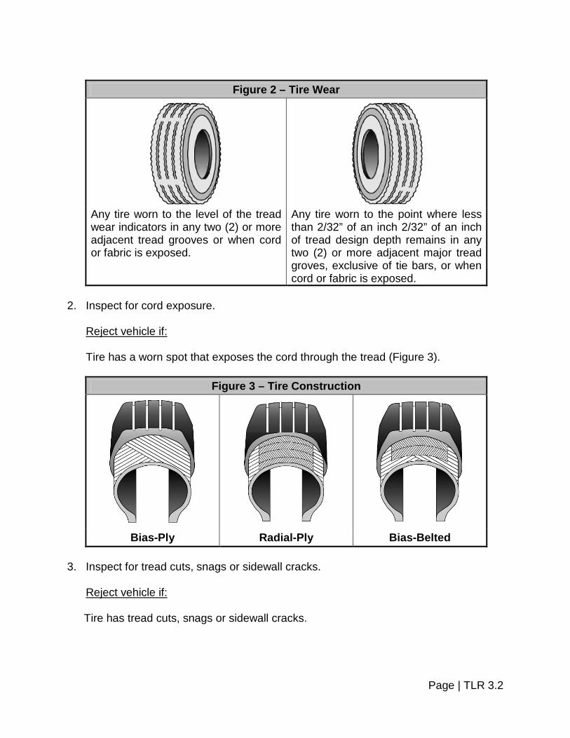
Figure 2 – Tire Wear
Any tire worn to the level of the tread wear indicators in any two (2) or more adjacent tread grooves or when cord or fabric is exposed.
Any tire worn to the point where less than 2/32” of an inch 2/32” of an inch of tread design depth remains in any two (2) or more adjacent major tread groves, exclusive of tie bars, or when cord or fabric is exposed.
2. Inspect for cord exposure. Reject vehicle if: Tire has a worn spot that exposes the cord through the tread (Figure 3).
Figure 3 – Tire Construction
Bias-Ply Radial-Ply Bias-Belted 3. Inspect for tread cuts, snags or sidewall cracks. Reject vehicle if:
Tire has tread cuts, snags or sidewall cracks.
Page | TLR 3.2

4. Inspect for bumps, bulges or knots. Reject vehicle if:
Tire has visible bumps, bulges or knots indicating partial failure or separation of the tire structure.
5. Inspect for regrooved or recut tires. Reject vehicle if:
Tire has been regrooved or recut below original groove depth, except special tires that have undertread rubber for this purpose and can be identified as such by markings on the tire.
6. Inspect wheel bolts, nuts or lugs. Reject vehicle if: Wheel bolts, nuts, studs or lugs are loose, missing or damaged. 7. Inspect for wheel damage. Reject vehicle if:
Any part of wheel is bent, cracked, rewelded, damaged or has elongated boltholes so as to affect safe operation of the vehicle.
8. Inspect for equal tire size. Reject vehicle if: Tires on the same axle are not the same type construction or size. Note: As a general rule, do not mix different size tires on the same axle.
However, it may be permissible to mount tires having different size descriptions (U.S. standard metric) on the same axle when construction, dimensions and load capacity are compatible. Consult the manufacturer for specific permissible practice.
9. Inspect for restricted usage markings on tires. Reject vehicle if:
Tire is marked "FOR FARM USE ONLY", "OFF HIGHWAY USE ONLY" or "FOR RACING USE ONLY", etc.
Page | TLR 3.3


SECTION 4 – BRAKES
BRAKE EQUIPMENT REQUIRED
Trailers, semi-trailers, trailer coaches: Weight not exceeding 3,000 pounds. Requirement: Need not have brakes as long as weight of the trailer does not exceed forty percent
(40%) of the weight of the towing vehicle. Trailer, semi-trailer, trailer coach: Weight more than 3,000 – 6,000 pounds. Requirement: Brakes are required on at least one (1) axle and the trailer must also be equipped
with a breakaway brake device. Trailer, semi-trailer, trailer coach: Weight over 6,000 pounds. Requirement: Brakes are required on all wheels and be equipped with breakaway brake device.
ELECTRIC BRAKES – FUNCTION Procedure: 1. Inspect for loose or corroded terminal connections, broken, frayed or unsupported
wires. Reject vehicle if: a. Electrical terminals are loose or excessively corroded. b. Wires or connectors are broken, frayed or not properly supported. 2. Inspect for braking action. Reject vehicle if: Braking action is absent on one (1) or more of the wheels required to be equipped
with brakes.
Page | TLR 4.1

3. Inspect for breakaway brake device. Pull pin in the device and observing automatic brake application. Reject vehicle if:
a. Missing or inoperable breakaway brake device.
b. Missing or broken wire(s) on breakaway device.
c. If no application occurs.
d. Brakes do not release when pin is returned to the breakaway switch.
e. Brakes do not remain applied for at least fifteen (15) minutes.
EMERGENCY BRAKE – MANUAL CONTROL Procedure: Brakes can be checked for operation by activating manual control without activating tractor service brakes and attempting to move trailer while brakes are applied. Reject vehicle if: Brakes do not apply and release by operating manual control.
EMERGENCY BRAKE – AIR ONLY Procedure: 1. Connect trailer couplings and build up system to governor cutout point. 2. Stop engine and operate control, observe automatic trailer brake application. 3. Make a series of foot brake applications and observe automatic trailer brake
application. Reject vehicle if: 1. Emergency brakes do not apply automatically.
2. Brakes apply automatically when tractor pressure is above forty-five (45) PSI.
3. Brakes fail to apply automatically when pressure is by foot application.
Page | TLR 4.2
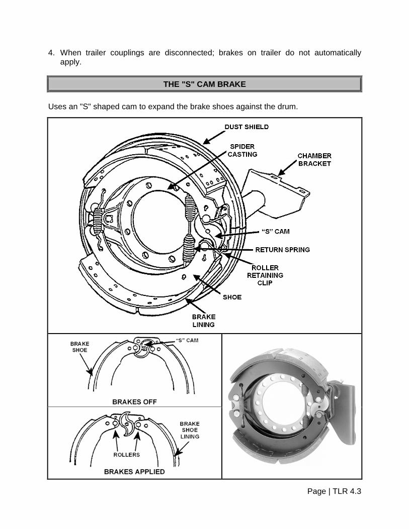
4. When trailer couplings are disconnected; brakes on trailer do not automatically apply.
THE "S" CAM BRAKE
Uses an "S" shaped cam to expand the brake shoes against the drum.
Page | TLR 4.3
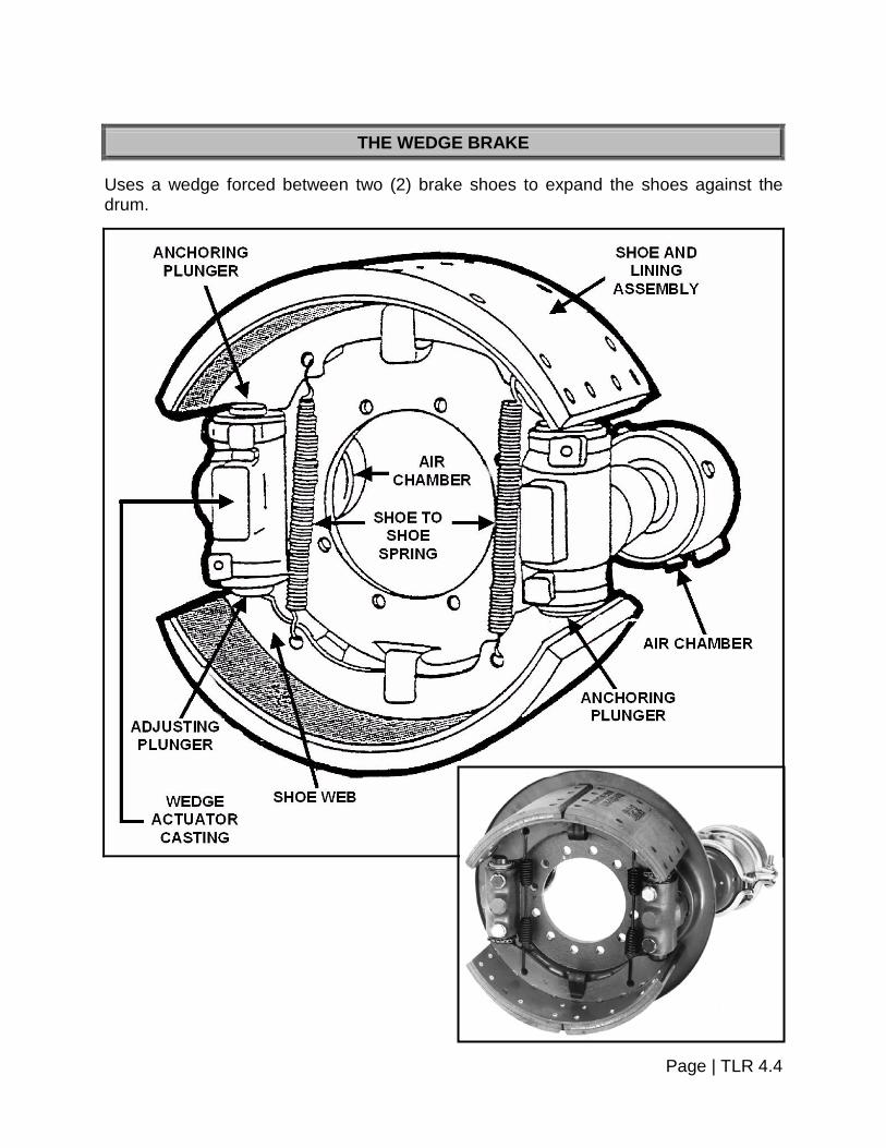
THE WEDGE BRAKE
Uses a wedge forced between two (2) brake shoes to expand the shoes against the drum.
Page | TLR 4.4

THE DISC BRAKE
Uses two (2) brake pads pinched against a rotating disc or rotor.
DISC BRAKE, SIDE VIEW
(This particular disc is from a hydraulic system.)
EXAMPLE DISC BRAKE (This particular disc is from an
air system.)
Page | TLR 4.5

Note: Trucks and truck-tractors having three (3) or more axles need not have brakes on front axle on vehicles manufactured prior to July 25, 1980.
HYDRAULIC BRAKES – SURGE BRAKES – VACUUM ASSIST HYDRAULIC
Procedure: 1. Check master cylinder for fluid level. Reject vehicle if: Master cylinder less than one-quarter (¼) full. Note: Normally to be inspected when readily visible or problems are apparent.
2. Inspect all lines and hoses and wheel areas for visual leaks, worn brake hoses,
crimped or restricted lines. Reject vehicle if:
a. Seeping or swelling brake hose(s) under application of pressure.
b. Any visually observed leaking hydraulic fluid in the brake system.
c. Hydraulic hose(s) chafed through outer cover to fabric layer.
d. Fluid lines or connections restricted, crimped, cracked or broken. 3. Inspect vacuum assisted hydraulic system. 4. Depress pedal hard and while holding it, start engine. 5. If the power unit is working, the pedal should drop appreciably under foot pressure. Reject vehicle if: Power assist unit fails to operate.
BROKEN OR UNSECURED PARTS AND LOOSE CONNECTIONS Procedure: Visually inspect brake components at the wheels.
Page | TLR 4.6
Reject vehicle if: 1. No braking action occurs upon application of the service brakes.
2. There is missing or broken components such as shoes, linings, pads, springs,
anchor pins, spiders, cam rollers, push rods and air chamber mounting bolts. 3. Components are loose or insecurely mounted. 4. There is an audible air leak at the brake chamber. 5. Any lining or pad is not firmly attached to the shoe or is saturated with oil, grease or
brake fluid. 6. Readjustment limits are as follows: With engine off and reservoir pressure of eighty (80) to ninety (90) PSI with brakes
fully applied.
a. One (1) brake at one-quarter of an inch (¼”) or more beyond the readjustment limit. Example: Type 30 clamp type brake chamber push rod measured at two and one-quarter of an inch (2¼”) would be one (1) defective brake.
b. Two (2) brakes at the readjustment limit or less than one-quarter of an inch (¼”)
beyond the readjustment limit also equal one (1) defective brake. Example: Clamp type 30 push rods measure:
Two (2) at 2-1/8”;
One (1) at 2-1/8” and one (1) at 2”; or,
Two (2) at 2”. Each example would equal one (1) defective brake. 7. Mismatched brake chamber types/sizes are present across an axle. 8. Slack adjusters of mismatched effective lengths are present across an axle.
BRAKE LINING Procedure: 1. Visually inspect brake lining for excessive wear or missing pieces. 2. Visually inspect brake linings for saturation with oil or grease.
Page | TLR 4.7

Equipment: Measuring device. Reject vehicle if: 1. Vehicle is equipped with air brakes and lining is less than one-quarter of an inch (¼”)
thick or if lining is worn to wear indicator (if so marked) measured at the shoe center for drum brakes or less than one-eighth of an inch (1/8”) for disc brakes.
2. Vehicle is equipped with hydraulic and/or electric brakes and the lining is one-
sixteenth of an inch (1/16”) or less in thickness at the shoe center for drum brakes. 3. There is a missing brake(s) on any axle required to have brakes. 4. Any brake lining is saturated with oil or grease.
BRAKE DRUMS Procedure: Visually inspect the brake drums for cracks. Reject vehicle if: 1. The brake drums are cracked on the friction surface and the crack extends to the
open edge or if the outside surface of drum is cracked. 2. The friction surface of the drum is contaminated with oil, grease or brake fluid. 3. The lining thickness is less than three-sixteenths of an inch (3/16”) for a shoe with a
continuous strip of lining or one-quarter of an inch (¼”) for a shoe with two (2) pads for drum brakes or to wear indicator if lining is so marked, or less than one-eighth of an inch (1/8”) for air disc brakes, and one-sixteenth of an inch (1/16”) or less for hydraulic disc and electric brakes.
4. Any portion of the brake drum is missing.
BRAKE HOSE AND TUBING Procedure: Visually inspect brake hose and tubing for damage, leaks and improper splicing.
Page | TLR 4.8

Reject vehicle if: 1. Hoses show any damage extending through the outer reinforcement ply. (Rubber
impregnated fabric cover is not a reinforcement ply.) (Thermoplastic nylon may have braid reinforcement or color difference between cover and inner tube. Exposure of second color is cause for rejection.)
2. Bulging or swelling occurs when air pressure is applied. 3. There is an audible leak in a hose at other than a proper connection. 4. Hose splices can be moved or separated by hand. 5. Hose splices are made by sliding the hose ends over a piece of tubing and clamping
the hose to the tube. 6. Tubing is cracked, broken or crimped.
AIR SYSTEM Procedure: 1. Inspect the complete system for improper air loss. Reject vehicle if: a. Valves are missing or inoperable. b. Trailer brakes fail to activate properly. 2. Inspect air reservoir. Reject vehicle if: Mounting bolts are broken, missing or loose (not including defective bushings). 3. Visually inspect vacuum brake system. Reject vehicle if:
a. Vacuum reserve is insufficient to permit one (1) full brake application after engine is shut off.
b. Vacuum hose(s) or line(s) are restricted, chafed through outer cover to cord ply,
crimped, cracked, broken or has collapse of vacuum hose(s) when vacuum is applied.
Page | TLR 4.9
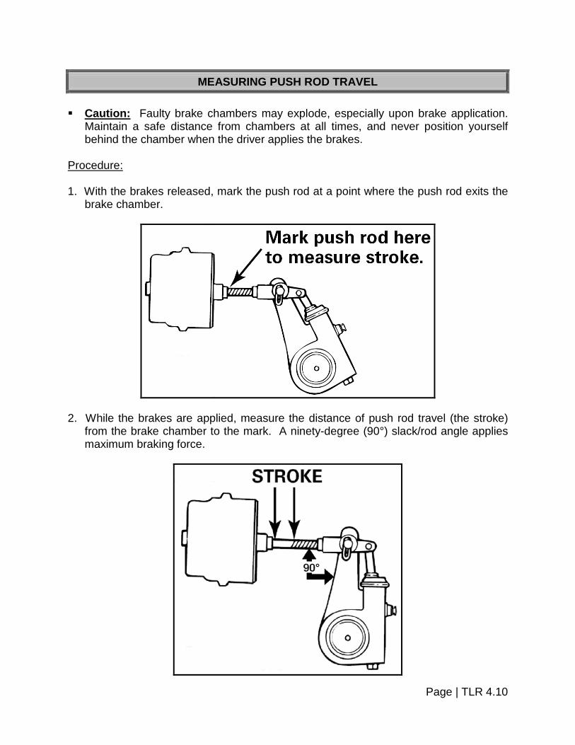
MEASURING PUSH ROD TRAVEL Caution: Faulty brake chambers may explode, especially upon brake application.
Maintain a safe distance from chambers at all times, and never position yourself behind the chamber when the driver applies the brakes.
Procedure: 1. With the brakes released, mark the push rod at a point where the push rod exits the
brake chamber.
2. While the brakes are applied, measure the distance of push rod travel (the stroke)
from the brake chamber to the mark. A ninety-degree (90°) slack/rod angle applies maximum braking force.
Page | TLR 4.10
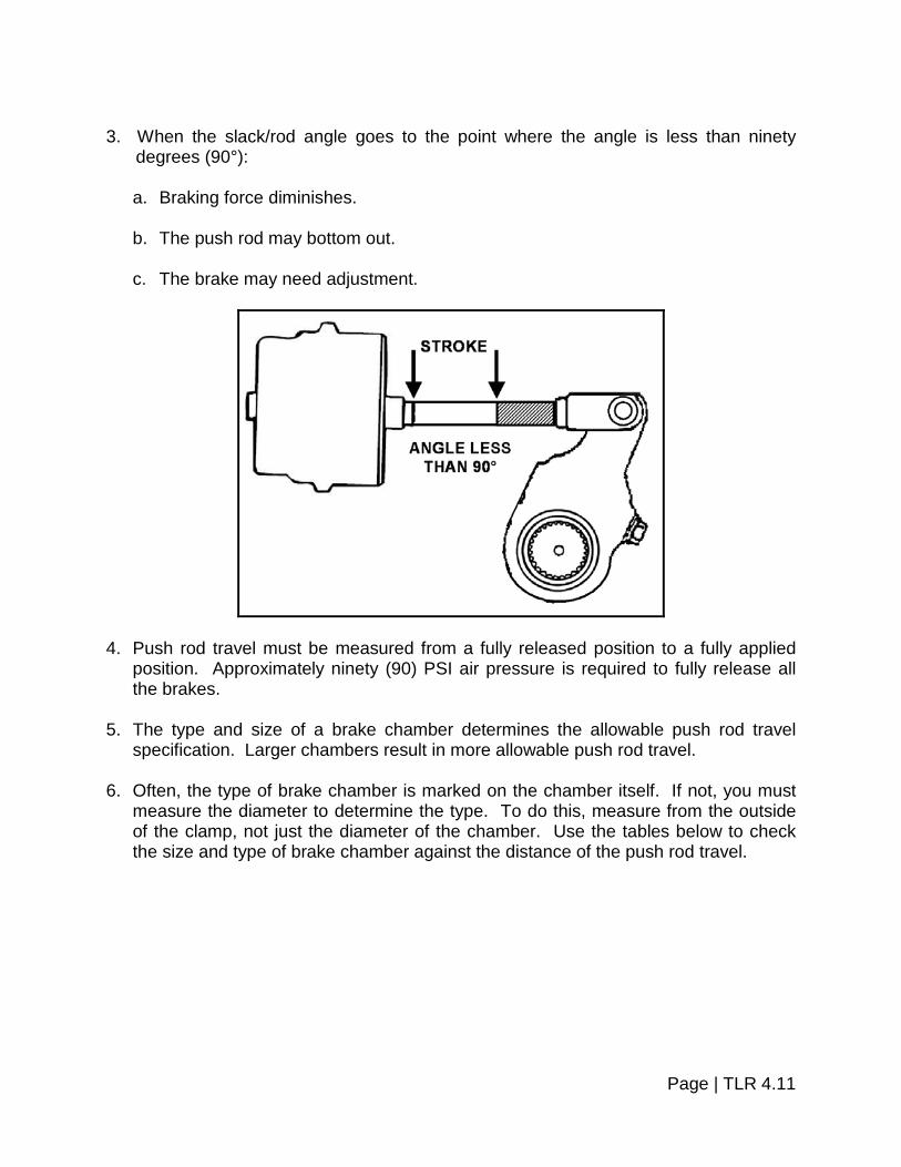
3. When the slack/rod angle goes to the point where the angle is less than ninety
degrees (90°):
a. Braking force diminishes.
b. The push rod may bottom out.
c. The brake may need adjustment.
4. Push rod travel must be measured from a fully released position to a fully applied position. Approximately ninety (90) PSI air pressure is required to fully release all the brakes.
5. The type and size of a brake chamber determines the allowable push rod travel
specification. Larger chambers result in more allowable push rod travel. 6. Often, the type of brake chamber is marked on the chamber itself. If not, you must
measure the diameter to determine the type. To do this, measure from the outside of the clamp, not just the diameter of the chamber. Use the tables below to check the size and type of brake chamber against the distance of the push rod travel.
Page | TLR 4.11
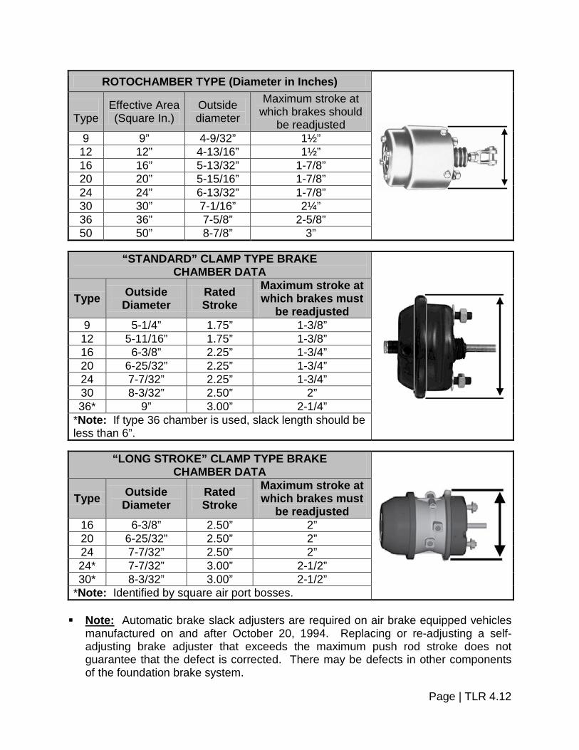
ROTOCHAMBER TYPE (Diameter in Inches)
Type
Effective Area (Square In.)
Outside diameter
Maximum stroke at which brakes should
be readjusted 9 9” 4-9/32” 1½”
12 12” 4-13/16” 1½” 16 16” 5-13/32” 1-7/8” 20 20” 5-15/16” 1-7/8” 24 24” 6-13/32” 1-7/8” 30 30” 7-1/16” 2¼” 36 36” 7-5/8” 2-5/8” 50 50” 8-7/8” 3”
“STANDARD” CLAMP TYPE BRAKE
CHAMBER DATA
Type Outside Diameter
Rated Stroke
Maximum stroke at which brakes must
be readjusted 9 5-1/4” 1.75” 1-3/8” 12 5-11/16” 1.75” 1-3/8” 16 6-3/8” 2.25” 1-3/4” 20 6-25/32” 2.25” 1-3/4” 24 7-7/32” 2.25” 1-3/4” 30 8-3/32” 2.50” 2” 36* 9” 3.00” 2-1/4”
*Note: If type 36 chamber is used, slack length should be less than 6”.
“LONG STROKE” CLAMP TYPE BRAKE
CHAMBER DATA
Type Outside Diameter
Rated Stroke
Maximum stroke at which brakes must
be readjusted 16 6-3/8” 2.50” 2” 20 6-25/32” 2.50” 2” 24 7-7/32” 2.50” 2” 24* 7-7/32” 3.00” 2-1/2” 30* 8-3/32” 3.00” 2-1/2”
*Note: Identified by square air port bosses. Note: Automatic brake slack adjusters are required on air brake equipped vehicles
manufactured on and after October 20, 1994. Replacing or re-adjusting a self-adjusting brake adjuster that exceeds the maximum push rod stroke does not guarantee that the defect is corrected. There may be defects in other components of the foundation brake system.
Page | TLR 4.12

INSPECTING WEDGE BRAKE ADJUSTMENT Procedure: 1. With the inspection hole cover removed from the brake dust shield, check the
adjustment at each wheel visually or using a feeler gauge.
2. With the brakes fully released, inspect this distance from the drum to the brake shoe
(lining surface). This distance must not exceed one-sixteenth of an inch (1/16”). (If using a feeler gauge, the gap must not exceed .0625).
Page | TLR 4.13

INSPECTING LINING WITH FEELER GAUGE
Procedure: If the edge of the lining is not visible, mark the lining and then apply the brakes. When the brake shoe moves, watch the mark or measure the movement with a gauging device. Any brake shoe travel beyond one-sixteenth of an inch (1/16”) (.0625) is excessive. Failure of the brake shoes to move is a condition of improper maintenance.
CROSS SECTION OF WEDGE BRAKE MEASUREMENT Brake shoe contact or non-contact is also indicated by striking the drum with a metal tool. The drum will echo or ring if the shoes are not contacting; if the shoes are contacting the drum, a dull sound will result.
ANTILOCK BRAKE SYSTEM Procedure: Inspection antilock brake system in accordance with the ABS Inspection Procedure. Reject vehicle if: ABS, including the ABS malfunction lamp, does not function in accordance with the ABS Inspection Procedure.
Page | TLR 4.14

ABS Inspection Procedure – U.S. Field Reference Version
Manufacture Date Truck or Bus with Hydraulic Brakes
Before March 1, 1999 ABS is not required.
On or after March 1, 1999
Begin with the ignition key in the “off” position. Turn the ignition key “on”. Confirm that the truck or bus ABS malfunction lamp turns on and after a few seconds the lamp goes out. Any other response indicates a malfunction of the ABS.
Manufacture Date Truck or Bus with Air Brakes
Before March 1, 1998 ABS is not required.
On or after March 1, 1998
Begin with the ignition key in the “off” position. Turn the ignition key “on”. Confirm that the truck or bus ABS malfunction lamp turns on and after a few seconds the lamp goes out. Any other response indicates a malfunction of the ABS.
Manufacture Date Truck or Bus with Air Brakes Equipped to Tow Another Vehicle with Air Brakes
Before March 1, 1998 ABS is not required.
On or after March 1, 1998
Begin with the ignition key in the “off” position. Turn the ignition key “on”. Confirm that the ABS malfunction lamp turns on and after a few seconds the lamp goes out. Any other response indicates a malfunction of the ABS.
On or after March 1, 2001
Not connected to any trailer or connected to a trailer manufactured before March 1, 2001:
Begin with the ignition key in the “off” position. Turn the ignition key “on”. Confirm that the truck or bus ABS malfunction lamp turns on and after a few seconds the lamp goes out. Any other response indicates a malfunction of the ABS. The trailer ABS malfunction lamp will not illuminate in this case.*
Connected to a trailer manufactured on or after March 1, 2001:
Begin with the ignition key in the “off” position. Turn the ignition key “on”. Confirm that both the truck or bus, and trailer ABS dash lamps turn on and after a few seconds the lamps go out. Any other response indicates a malfunction of the ABS.
Page | TLR 4.15

Manufacture Date Truck Tractor with Air Brakes
Before March 1, 1997 ABS is not required.
On or after March 1, 1997
Begin with the ignition key in the “off” position. Turn the ignition key “on”. Confirm that the ABS malfunction lamp turns on and after a few seconds the lamp goes out. Any other response indicates a malfunction of the ABS.
On or after March 1, 2001
Not connected to any trailer or connected to a trailer manufactured before March 1, 2001:
Begin with the ignition key in the “off” position. Turn the ignition key “on”. Confirm that the tractor ABS malfunction lamp turns on and after a few seconds the lamp goes out. Any other response indicates a malfunction of the ABS. The trailer ABS malfunction lamp will not illuminate in this case.*
Connected to a trailer manufactured on or after March 1, 2001:
Begin with the ignition key in the “off” position. Turn the ignition key “on”. Confirm that both tractor and trailer dash-mounted ABS malfunction lamps turn on and after a few seconds the lamps go out. Any other response indicates a malfunction of the ABS.
Manufacture Date Trailer with Air Brakes (Including a Trailer Converter Dolly)
Before March 1, 1998 ABS is not required.
On or after March 1, 1998
Connected to a truck or truck tractor manufactured before March 1, 1997.
Apply the brake pedal and confirm that the trailer-mounted ABS malfunction lamp turns on and after a few seconds goes out before the brake is released. Any other response indicates a malfunction of the ABS.
Connected to a truck or truck tractor manufactured on or after March 1, 1997. **
Begin with the ignition key in the “off” position. Turn the ignition key “on”. Confirm that the trailer-mounted ABS malfunction lamp turns on and after a few seconds the lamp goes out. Any other response indicates a malfunction of the ABS.
Page | TLR 4.16

Manufacture Date Continued – Trailer with Air Brakes (Including a Trailer Converter Dolly)
On or after March 1, 2001
Connected to a truck or truck tractor manufactured before March 1, 2001.
Test in the same manner as trailers manufactured on or after March 1, 1998.
Connected to a truck or truck tractor manufactured on or after March 1, 2001.
Begin with the ignition key in the “off” position. Turn the ignition key “on”. Confirm that both the trailer dash-mounted ABS malfunction lamp and the trailer-mounted ABS malfunction lamp turn on and after a few seconds the lamps go out. Any other response indicates a malfunction of the ABS.
* The trailer ABS lamp in the dash only operates when the tractor is connected to a trailer manufactured after March 1, 2001.
** Power to the trailer’s ABS circuit is delivered by a dedicated circuit from the truck
tractor. In the U.S. the following vehicles are exempt from the requirements to have ABS: Any trailer that has a width of more than 102.36 inches with extendable equipment in
the fully retracted position and is equipped with two short track axles in a line across the width of the trailer.
Any vehicle equipped with an axle that has a gross axle weight rating (GAWR) of
29,000 pounds or more. Any truck or bus that has a speed attainable in 2 miles of not more than 33 MPH. Any truck that has a speed attainable in 2 miles of not more than 45 MPH, an
unloaded vehicle weight that is not less than 95 percent of its gross vehicle weight rating (GVWR), and no capacity to carry occupants other than the driver and operating crew.
Any trailer that has a GVWR of more than 120,000 pounds and whose body
conforms to that described in the definition of heavy hauler trailer set forth in S4 of the Federal Motor Carrier Safety Administration regulations; Heavy hauler trailer means a trailer which has one or more of the following characteristics, but which is not a container chassis trailer:
Page | TLR 4.17

Its brake lines are designed to adapt to separation or extension of the vehicle frame, or
Its body consists only of a platform whose primary cargo-carrying surface is not
more than 40 inches above the ground in an unloaded condition, except that it may include sides that are designed to be easily removable and a permanent "front end structure" as that term is used in §393.106 of the Federal Motor Carrier Safety Administration regulations.
Any trailer that has an unloaded vehicle weight which is not less than 95 percent of
its GVWR. Any load divider dolly.
Page | TLR 4.18


SECTION 5 – FRAME
BASIC FRAME COMPONENTS
Two frame rails: The frame rails are the foundation of the vehicle. Cross-members:
Cross-members hold the frame rails the proper distance apart and control rotational and longitudinal motion. They provide protection and support for wires and air lines that cross the vehicle from one side to the other.
Sliding Sub Frame:
Both full frame and short frame trailers may have a sliding sub frame. This allows the axles to be moved in relationship to the trailer. (Also called sliding tandem axles.)
Procedure: 1. Inspect Sliding Sub Frame. Reject vehicle if:
a. Frame cracked, loose, sagging or broken.
b. Broken or loose bolts or brackets.
c. Cracked or loose frame members. 2. Inspect adjustable axle. Reject vehicle if:
a. Adjustable axle assembly (sliding sub-frame) with any locking pins missing or not engaged.
b. Locking bar not closed or not in the locked position.
Note: Refer to Section 12 of the Heavy Truck and Bus Section.
Page | TLR 5.1

3. Inspect Rear End Protection. Reject vehicle if:
a. Bottom of the device is more than thirty inches (30”) from the ground with vehicle loaded.
b. There is more than twenty-four inches (24”) between the devices if more than
one (1) is used.
c. The maximum transverse distance from the widest part of the vehicle at the rear to the device is more than eighteen inches (18”).
d. The device is more than twenty-four inches (24”) forward of the rear most part of
the vehicle.
e. The device is not made of a substantial material or is not securely fastened.
SLIDING SUB FRAME AND REAR END PROTECTION
Page | TLR 5.2


SECTION 6 – SAFETY DEVICES
MUD FLAPS AND FENDERS
Equipment: Measuring Device. Procedure: 1. Inspect fenders and flaps to determine that they are solidly attached and of
substantial material to cover the full width of the tread to prevent throwing dirt, water or other material onto the windshield of vehicles following.
2. If a flap is required, the following standards will be followed:
The splash pans stone throw protection device shall extend laterally for at least the width of the tires and shall be composed of material or flexible materials substantial enough to withstand ripping or tearing by ordinary means, and also shall be long enough so that the clearance from the ground to the bottom edge of the device shall be not more than one-half (½) of the distance from the bottom edge of the device to the center line of the rearmost axle of the vehicle. However, the bottom edge of such device need be no closer to the road than six inches (6”) when loaded.
Reject vehicle if: 1. Fenders of flaps are not solidly attached. 2. Are not constructed of substantial materials. 3. Are not of sufficient size or are not attached properly. 4. Do not meet the criteria set out in the following pictures. 5. Fenders do not cover the entire tread width. 6. Come into contact with the tire or wheel.
Page | TLR 6.1

Flaps required, as the distance from rear edge of truck body to the ground is over half (½) the distance from center of rearmost axle to rear edge of body.
Flaps required, as the distance from rear edge of fender to the ground is over half (½) the distance from center of rearmost axle to rear edge of fender.
FIRE EXTINGUISHER
TRAILER COACHES ONLY Procedure: 1. Inspect only trailer coaches to ensure that the fire extinguisher is present, is in good
usable condition and is easily accessible. 2. If the extinguisher is of a CO2 type it must be not less five (5) pound capacity, and if
it is a dry chemical type it must be not less than two and one-half (2½) pound capacity.
Reject vehicle if: 1. Fire extinguisher is not present or is not of an approved type. 2. Fire extinguisher is not in usable condition. 3. Fire extinguisher is not easily accessible.
Page | TLR 6.2

