state-of-the-art filter regeneration management · state-of-the-art filter regeneration management...
TRANSCRIPT
State-of-the-Art Filter Regeneration Management
Concepts realized by LDV companies
Uwe H. Zink
Timothy V. Johnson

Diesel TechnologiesCorning Proprietary
2
Agenda• Introduction
– Primary task and elements of DPF system management• Overview of actual active DPF system designs• DPF system management concepts
– Temperature control & management– Regeneration management concepts
• Summary

Diesel TechnologiesCorning Proprietary
3
Elements of Filter Regeneration Management:Control DPF soot load and regeneration
• Monitor, detect, and control filter loading conditions– Primarily: Soot– Secondarily: Ash
• Initiate and control regeneration to targeted inlet temperatures– Within entire engine map and at transient conditions

Diesel TechnologiesCorning Proprietary
4
DPF Soot loading considerations• Targeted operational soot load
– Regeneration frequency• Driven by e.g. engine parameters
(e.g. oil dilution)– Fuel economy
• Driven by regeneration frequency and pressure drop
• Filter model– Soot accumulated as function of
engine-out performance– “Vehicle mission profile”– Residual soot from previous
regeneration
• DPF pressure drop vs. soot load characteristics
• Impact of ash load shifting Δp“calibration”
Source:
Peugeot
Ref.: Fiat GM Powertrain (1)
Ref.: PSA
DPF Differential Pressure as Function of Exhaust Mass Flo
0
50
100
150
200
250
300
350
0 50 100 150 200 250 300 350 400exhaust mass flowrate [kg/hr]
deltaP [mbar]
10 g/l
8 g/l
4 g/l
0 g/l

Diesel TechnologiesCorning Proprietary
5
Engine management strategy based upon multiple injections ensures DPF inlet temperature across wide range of engine mapSource: Fiat GM Powertrain (1)
Note: Two DOCs upfront of catalyzed DPF
Different injection variants employed at different engine load conditions to ensure required filter inlet temperature

Overview of Actual ActiveDPF Systems

Diesel TechnologiesCorning Proprietary
7
Active DPF SystemSource: Fiat GM Powertrain (1)

Diesel TechnologiesCorning Proprietary
8
Active DPF SystemSource: DCX (3)

Diesel TechnologiesCorning Proprietary
9
DOC + CDPF System at Hyundai-KiaSource: HMC-Kia presentation (5)
Diesel TechnologiesCorning Proprietary
10
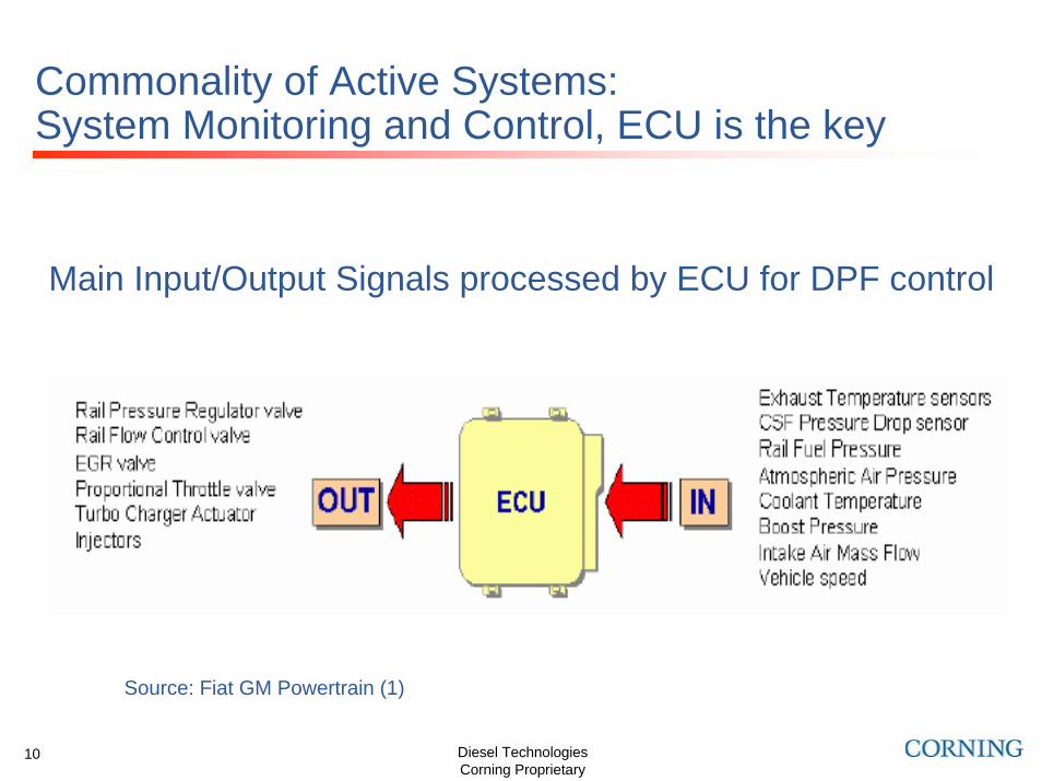
Commonality of Active Systems:System Monitoring and Control, ECU is the key
Main Input/Output Signals processed by ECU for DPF control
Source: Fiat GM Powertrain (1)

Diesel TechnologiesCorning Proprietary
11
DPF Control Software ArchitectureSource: Fiat GM Powertrain (1)

Approaches to ensure sufficient filter inlet temperature

Diesel TechnologiesCorning Proprietary
13
Filter Heating StrategiesInjection Variants for DPF RegenerationSource: DCX (2)
Normal OperationVE1 VE2 HE NE1
°CATDC
VE1 VE2 HE NE1
°CATDC
CAT Heating
DPF-RegenerationVE1 VE2 HE NE1
°CATDCDPF-Regeneration (coasting) NE2
°CATDC
VE1 Pilot Injection 1VE2 Pilot Injection 2HE Main InjectionNE1 Post Injection 1NE2 Post Injection 2

Diesel TechnologiesCorning Proprietary
14
Closed loop control of exhaust gas temperature ensures reliable regeneration process also during transient operationSource: Fiat GM Powertrain (1)

Regeneration Management

Diesel TechnologiesCorning Proprietary
16
Flow Diagram DPF RegenerationSource: BMW (2)

Diesel TechnologiesCorning Proprietary
17
Function of the DPF SystemRegeneration Control of the DPFSource: DCX (2)

Diesel TechnologiesCorning Proprietary
18
Control systems enable tight thermal control during regeneration in city mode driving and key-off events-as observed during Corning on-road vehicle test Source: Corning (6)
Vehicle: 2.2l, EU IV calibrated passenger car, OEM calibration, OE-Filter replaced by Corning DuraTrap®AT Filter
Example of the thermocouple readings during a city test in which the regeneration was terminated two times when the driver stopped the engine.
Diesel TechnologiesCorning Proprietary
19
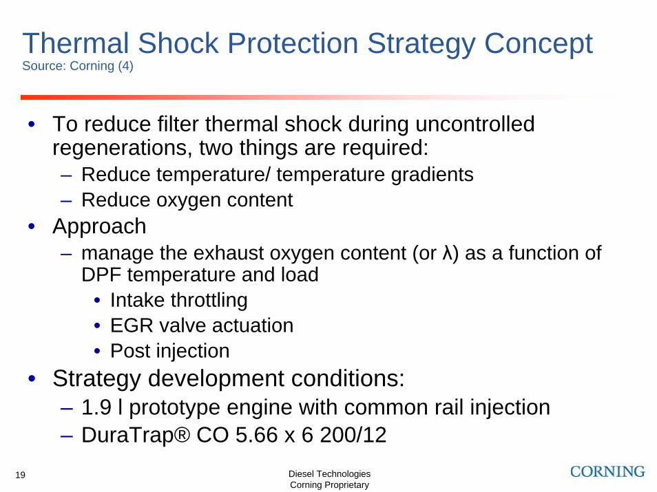
Thermal Shock Protection Strategy ConceptSource: Corning (4)
• To reduce filter thermal shock during uncontrolled regenerations, two things are required:– Reduce temperature/ temperature gradients– Reduce oxygen content
• Approach– manage the exhaust oxygen content (or λ) as a function of
DPF temperature and load• Intake throttling • EGR valve actuation• Post injection
• Strategy development conditions:– 1.9 l prototype engine with common rail injection– DuraTrap® CO 5.66 x 6 200/12

Diesel TechnologiesCorning Proprietary
20
DPF Thermal Shock Protection Strategy with Intake throttling, EGR, Post Injection (on engine)
• Significant reduction in both peak filter temperatures and maximum temperature gradients
• Uncontrolled regenerations eliminated
• Key enabler for lower filter system cost
Thermal shock protection strategy ON:
P e ak T e m p e ra tu re s in D P F
0
1 00
2 00
3 00
4 00
5 00
6 00
7 00
8 00
9 00
1 0 00
1 2 3 4 5 6 7 8 9 10 11 12 13 14 15 16 17 18 19 20 21
wo/ TSP
T e s tru n
Te
mp
era
ture
[
In le t S ide T e m pe ra tu re s
O utle t S id e T em p e ra tu re s
- 400 oC
OFFStrategy ON
P e ak T e m p e ra tu re s in D P F
0
1 00
2 00
3 00
4 00
5 00
6 00
7 00
8 00
9 00
1 0 00
1 2 3 4 5 6 7 8 9 10 11 12 13 14 15 16 17 18 19 20 21
wo/ TSP
T e s tru n
Te
mp
era
ture
[
In le t S ide T e m pe ra tu re s
O utle t S id e T em p e ra tu re s
- 400 oC
OFFStrategy ON
P e a k A b s o lu te T e m p e ra tu re G ra d ie n ts in D P F
0
1 0 0
2 0 0
3 0 0
4 0 0
5 0 0
6 0 0
7 0 0
1 2 3 4 5 6 7 8 9 1 0 1 1 1 2 1 3 1 4 1 5 1 6 1 7 1 8 1 9 2 0 2 1 w o /T S P
T e s tru n
Te
mp
era
ture
Gra
die
nt
[°
In le t S id e T e m p era tu re G ra d ie n tsO utle t S id e T em pe ra tu re G rad ien ts
OFF
- 450 oC/cm
Strategy ON
Source: Corning (4)

Diesel TechnologiesCorning Proprietary
21
Summary• Advanced DPF regeneration management strategies are implemented in LDV
application– Filter loading monitoring and control
• Multiple, redundant and thus plausible soot & ash control– Regeneration initiation & control
• In-cylinder based• Post injection timing & quantity• Insurance that system is at required operating temperature
• Thermal Shock Protection Strategy demonstrated as concept
• It is conceivable that similar strategies need to be applied to HDV as well
• The control logics would apply even if non-in-cylinder DPF heating concepts are being used – Possible application of in-cylinder late injections, “mild” post-injections,
throttling, etc. for system warm-up phase prior to regeneration initiation
Diesel TechnologiesCorning Proprietary
22
References1. G. Boretto, et al.; 2004V068, Fisita Barcelona May 2004
2. W. Mattes, et al.; MTZ 7-8/2004 Vol 65
3. “Das neue Mercedes Benz Dieselpartikelfilterkonzept fuer PKW in Verbindung mit der AbgasstufeEU4”; J. Schommers, et al.; 25. Wiener Motorensymposium, April 2004
4. “Regeneration Control – Key to successful application of new DPF systems”, Zink et al., Proceedings of 13. Aachen Kolloquium Fahrzeug- und Motorentechnik, October 2004.
5. “Application of Catalyzed Diesel Particulate Filter System (CPF) To Small SUVs for Euro IV”, WonkunKim, et al., 4th HMC Diesel Symposium, October 21, 2004
6. “Performance and Durability Evaluation of the new Corning DuraTrap® AT Diesel Particulate Filter –Results from Engine Bench and Vehicle Tests“, (in Engl.) Heibel et al., To be published: Proceedings of 14. Aachen Kolloquium Fahrzeug- und Motorentechnik, October 2005.