state of the art and technology -...
TRANSCRIPT

State of the Art and Related Technologies
ITEA2 11020 Project
VERSION 1.4
Editors Antonio M. Ortiz (Institut Mines-Telecom)
Contributors Alcatel, Arcelik, KoçSistem, Gemalto, GS
Technologies, Institut Mines-Telecom,
Instituto de Telecomunicaçöes,
Mobilera, MobiquiThings, Prodevelop,
Planet Media, Sen.se, Soft4Energy,
Starhome, Thales, University of Alcala,
University of Seville, UPV-PROS,
University Paris-Est Marne-la-Valée
Date January, 2014
Status Version 1.4

2
COPYRIGHT
Copyright 2014 The SITAC Consortium.
The information contained in this report is subject to change without notice and should not be construed
as a commitment by any members of the SITAC Consortium. In the event of any software or algorithms
being described in this report, the SITAC Consortium assumes no responsibility for the use or inability to
use any of its software or algorithms. The information is provided without any warranty of any kind and
the SITAC Consortium expressly disclaims all implied warranties, included but not limited to the implied
warranties of merchantability and fitness for a particular use.
This document may not be copied, reproduced, or modified in whole or in part for any purpose without
written permission from the SITAC Consortium. In addition to such written permission to copy, reproduce
or modify this document in whole or part, an acknowledgement of the authors of the document and all
applicable portions of the copyright notice must be clearly referenced.
All rights reserved.

3
DOCUMENT HISTORY
Version Date Editor Comments
0.1 Draft 1 June, 2013 Antonio M. Ortiz Initialization for partner contributions
0.1 Draft 2 June, 2013 Prodevelop Data storage & aggregation
0.1 Draft 3 June, 2013 UAH Data management
0.1 Draft 4 June, 2013 Prodevelop Review Data management section
0.1 Draft 5 July, 2013 Alcatel-Lucent Introduction to Data Management. Data
Collection
0.2 Draft 1 July 2013 Institut Mines-
Telecom
Contribution aggregation
0.3 Draft 1 August 2013 Planet Media Physical objects contribution
0. 3 Draft 2 September
2013
Institut Mines-
Telecom
Crowd-based Technologies contribution
0.3 Draft 3 September
2013
Instituto de
Telecomunicacoes
LTE: Low cost M2M and the proposed
D2D architecture contribution
0.3 Draft 4 October 2013 Prodevelop Apache Mahout for Hadoop
0.3 Draft 5 October 2013 UPV Web of Objects, Services and
Applications
0.3 Draft 6 November 2013 Gemalto ETSI architecture
0.3 Draft 9 December 2013 KoçSistem ZigBee, 6LoWPAN, Bluetooth
0.3 Draft 11 December 2013 UPEMLV Devices and communications, Data
Management, Crowd based
technologies
0.3 Draft 12 January 2014 UPEMLV Services and applications
0.3 Draft 13 January 2014 UAH References updated in Section 5
0.4 Draft 1 January 2014 IMT Updated contributions
0.4 Draft 2 January 2014 IMT Updated references in Section 4
0.4 Draft 3 January 2014 IMT Added introduction
4
1.0 Candidate January 2014 IMT First candidate version, copyright
added, homogeneous style, references
corrected, list of figures and tables
1.1 Candidate January 2014 IMT-UAH Included Social Networks description,
comments from UAH, and first global
check
1.2 Candidate
January 2014 IMT-UAH-US Included conclusions for chapters 3 and
4, comments from UAH, resource
modeling section from US
1.4 Final January 2014 IMT-US-Gemalto Added Section 7, format check and
general review

5
Table of Contents
1. Introduction .......................................................................................................................................... 10
1.1. Organization and Deliverables .................................................................................................... 11
2. Related Paradigms, Projects and Architectures ................................................................................. 12
2.1. Internet of Things ........................................................................................................................ 12
2.1.1. Internet of Things Architecture (IoT-A), FP7 project ........................................................... 12
2.1.2. FI-WARE ............................................................................................................................. 16
2.1.3. Web of Objects (WoO) ITEA2 project ................................................................................. 19
2.1.4. Standardized ETSI – TC – M2M architecture ..................................................................... 22
2.2. Social Networks........................................................................................................................... 25
2.2.1. Definition of Social Networks .............................................................................................. 25
2.2.2. Growth of Social Networks .................................................................................................. 26
2.2.3. Motives for Utilizing Social Networks .................................................................................. 26
2.2.4. Research Fields Underlying the Use of Social Networks.................................................... 26
3. Devices and Communications ............................................................................................................. 30
3.1. Physical Objects .......................................................................................................................... 30
3.1.1. Gateways ............................................................................................................................ 30
3.1.2. Repeaters ............................................................................................................................ 30
3.1.3. Sensors ............................................................................................................................... 31
3.1.4. Sensors enabled smartphones ........................................................................................... 32
3.1.5. Actuators ............................................................................................................................. 33
3.1.6. RFID .................................................................................................................................... 34
3.2. Network Technologies ................................................................................................................. 35
3.2.1. ZigBee ................................................................................................................................. 35
3.2.2. IPv6 over Low Power Wireless Personal Area Network (6LowPAN) .................................. 38
3.2.3. Bluetooth ............................................................................................................................. 40
3.2.4. Near Field Communication .................................................................................................. 41
3.2.5. Radio Frequency ID ............................................................................................................ 42
3.2.6. LTE: Low cost-M2M and the proposed D2D architecture ................................................... 45
3.3. Resource modeling ..................................................................................................................... 47
3.3.1. AMON .................................................................................................................................. 47
3.3.2. Device Kit ............................................................................................................................ 48
6
3.3.3. EDDL ................................................................................................................................... 48
3.3.4. ECHONET ........................................................................................................................... 48
3.3.5. IEEE 1451 ........................................................................................................................... 49
3.3.6. FlowTalk .............................................................................................................................. 49
3.3.7. Ptolemy ............................................................................................................................... 49
3.3.8. SensorML ............................................................................................................................ 49
3.3.9. ThingML .............................................................................................................................. 51
4. Services and Applications ................................................................................................................... 56
4.1. Service Creation and Discovery .................................................................................................. 56
4.1.1. Dynamic Host Configuration Protocol (DHCP) ................................................................... 56
4.1.2. Zeroconf, Bonjour, Avahi ..................................................................................................... 57
4.1.3. UPnP ................................................................................................................................... 57
4.1.4. Service Location Protocol (SLP) ......................................................................................... 57
4.1.5. Web Services Dynamic Discovery (WS-Discovery) ............................................................ 58
4.1.6. Discovering Services in the Internet of Things .................................................................... 58
4.2. Service Composition ................................................................................................................... 59
4.3. Services & Applications ............................................................................................................... 59
4.3.1. Apple Find My Friends ........................................................................................................ 60
4.3.2. Google Now ......................................................................................................................... 60
4.3.3. Waze ................................................................................................................................... 60
4.3.4. Amazon Cloud Services ...................................................................................................... 60
4.3.5. Uber ..................................................................................................................................... 60
4.3.6. Gimbal ................................................................................................................................. 61
4.3.7. Locale .................................................................................................................................. 61
5. Data Management ............................................................................................................................... 63
5.1. Data Collection ............................................................................................................................ 63
5.1.1. Data Collection via Mobile phones: Crowdsensing ............................................................. 65
5.2. Data Storage ............................................................................................................................... 66
5.2.1. SQL Scalable Technologies ................................................................................................ 66
5.2.2. NoSQL Databases .............................................................................................................. 67
5.2.3. Strengths and Weaknesses of NoSQL Databases ............................................................. 68
5.2.4. Comparison of some NoSQL technologies ......................................................................... 71
5.3. Data Aggregation ........................................................................................................................ 84

7
5.3.1. Hadoop Framework ............................................................................................................. 84
5.4. Data Analysis .............................................................................................................................. 85
5.4.1. Machine Learning: Techniques and Algorithm for Data Analysis ....................................... 86
5.4.2. Distributed and Parallel Architectures for Machine Learning .............................................. 91
6. Crowd-based Technologies ................................................................................................................ 98
6.1. Crowd-based Services ................................................................................................................ 98
6.2. Crowd-based Applications .......................................................................................................... 99
7. Security, trust, and privacy ................................................................................................................ 102
7.1. Legacy M2M architecture. ......................................................................................................... 102
7.2. Security concepts. ..................................................................................................................... 103
7.2.1. End to end security............................................................................................................ 103
7.2.2. Security of Communication ............................................................................................... 104

8
List of Figures
Figure 1. IoT-A general view. ..................................................................................................................... 15 Figure 2. FI-WARE overview of chapters and Generic Enablers................................................................ 17 Figure 3. Generic enblers of FI-WARE Data/Context chapter. ................................................................... 18 Figure 4. Main Generic Enablers of FI-WARE IoT chapters. ...................................................................... 19 Figure 5. Woo functional architecture. ........................................................................................................ 21 Figure 6. Generic architecture model standardized by ETSI TC M2M. ...................................................... 23 Figure 7. Horizontal approach in line with ETSI TC M2M specifications. ................................................... 25 Figure 8. A wireless sensor and actuator network. ..................................................................................... 33 Figure 9. WSAN architecture without explicit controllers. ........................................................................... 34 Figure 10. 6lowpan architecture .................................................................................................................. 39 Figure 11. Protocol stack ............................................................................................................................ 40 Figure 12. NFC structure ............................................................................................................................. 42 Figure 13. The LTE Network Controlled Device to Device Communication. .............................................. 47 Figure 15. TO END SECURITY USING THIRD PARTY. ......................................................................... 104 Figure 16. SSL Handshake from Oracle® Fusion Middleware Administrator's Guide. ............................ 108 Figure 17. SAML transaction. ................................................................................................................... 112 Figure 18. OpenID overview. .................................................................................................................... 113 Figure 19. OAuth overview........................................................................................................................ 114 Figure 20. GBA architecture. .................................................................................................................... 116

9
List of Tables
Table 1. Zigbee specifications and standards. ........................................................................................... 36 Table 2. Zigbee technical specifications. .................................................................................................... 37 Table 3.Common RFID frequency bands. .................................................................................................. 43 Table 4. Resource modeling comparative table.......................................................................................... 51 Table 5. Strengths and weaknesses of NoSQL databases. ....................................................................... 69 Table 6. Comparison of HBase, Cassandra, MongoDB, CouchDB, SimpleDB, Redis and Neo4j ............. 74 Table 7. Comparison of Scalaris, Riak, Terrastore, Voldemort, Tokyo cabinet/Tokyo Tyrant, CouchBase
and Hypertable. ........................................................................................................................................... 78
10
1. Introduction
The Internet of Things (IoT) envisions a world where everything is connected, from houses to cities,
going through vehicles and infrastructures, users will be able to handle millions of objects that can
sense the environment and communicate through wireless links.
Nowadays, the technology is evolving so fast that the computing and storage power are becoming
higher and higher, and the devices are reducing their size.
With that huge number of devices, often called “objects” or “things”, there exists the need for
managing such an amount of information; services offered by ubiquitous computing, and applications
derived from these services must be completely configurable and available for the users, so they can
customize the system capabilities to match their needs.
Considering an enormous number of devices with a massive number of users, the interactions of the
latter also play an important role in the system. Social Networks appear as a solution that models the
different user capabilities and relationships that can occur when making use of the system. They also
facilitate the cooperation among different users, and are a perfect environment where users can
share experiences, as well as devices.
The inclusion of objects in the Social Network brings new potential to the whole system, so enhancing
the interaction among users and devices, but also carrying new challenges in terms of modeling,
interactivity, security and trust among others, as well as adding more complexity to the management
of the whole system.
This new framework, composed by users and devices, is aimed at producing a huge amount of data
that have to be efficiently managed, requiring efficient collection, aggregation and analysis
mechanisms. Communications, mostly wireless, and the possibility of managing the system through
different devices (smartphones, tablets, PCs, etc.) augment the complexity of the system and
represent an amazing research challenge.
But how to make this system attractive for users and stakeholders may be the most difficult point;
how to manage all the information, making services available, and designing interesting crowd-based
applications is the main focus of the SITAC project.
SITAC project aims at creating a unifying architecture and ecosystem comprising platforms, tools and
methodologies that enable the seamless connection and cooperation of many types of network-
connected entities, whether systems, machines, devices or humans with handled devices. SITAC will
deliver an open platform to enable such actors to monetize their products and services (whether
communication infrastructures, installed sensors, data flows or labour) as well as share revenue,
much in the way that cloud computing platforms do. The project will innovate by using the ‘social
networking’ paradigm to facilitate and unify interactions both between people and devices and among
devices. It will propose a distributed framework for enabling the Web-based service representation of
smart spaces and the object they include.
To reach this goal, SITAC project mainly covers the following innovative aspects:
Facilitating seamless connection and cooperation among devices and users through

11
Facilitating seamless connection and cooperation among devices and users through the use
of social networks and crowd-based applications.
Allowing casual users to take control of such massively deployed objects in a convenient and
safe manner.
Providing a platform which enables the development of Social IoT and crowd-based
applications and its relevant business-wise ecosystem.
Enabling in-node content analysis and decision making to decrease the amount of data flows.
Addressing technical challenges related to data analysis and recommendation techniques
when leveraging the social network and crowd-based paradigms.
1.1. Organization and Deliverables
This deliverable is structured in seven main sections, which cover the main research aspects of the
project. Each section is further decomposed into a number of subsections. The followings are the
outline of this deliverable.
Related paradigms, projects and architectures: as key technological domains, this section
addresses the Internet of Things, and Social Networks paradigms, as well as some related
European research projects.
Devices and communications: this section, divided into physical objects and network
technologies shows an overview of the related technological developments that will be the
basis of the SITAC developments.
Services and applications: how users and devices capabilities are organized and structured is
detailed in this section, from service creation and composition, to application development.
Data management: a deep review on the state of the art related to data collection, aggregation
and analysis is presented in this section.
Crowd-based technologies: some this section reviews the state of the art in the design of
services and applications based on the crowd.
Security, trust and privacy: final user trustfulness is very important for the SITAC
developments. This section reviews several mechanisms related to the security, trust and
privacy that will be considered during the design and development of SITAC products.
12
2. Related Paradigms, Projects and Architectures
This section constitutes a review of the SITAC related technological developments in terms of paradigms
and architectures, as well as projects that afford similar scientific approaches. It is divided into Internet of
Things and Social Networks subsections, since they represent the most relevant approaches to the
SITAC paradigm.
2.1. Internet of Things
Nowadays, Internet of Things [1] represents a global network interconnecting smart objects by means of
extended Internet technologies. It is built on three pillars related to the ability of smart objects to be
identifiable, to communicate, and to interact, either among themselves, building networks of
interconnected objects, or with end-users or other entities in the network. IoT can be described from
different perspectives:
From the conceptual point of view, IoT is about entities acting as provides and/or consumers of
data related to the physical world. The focus is on data and information rather than on point-to-
point communications.
From a system-level standpoint, the IoT can be described as a highly dynamic and radically
distributed networked system, composed of a very large number of smart objects producing and
consuming information.
From a service-level perspective, the main issue related to how to integrate or compose the
functionalities and/or resources provided by smart objects into services.
Finally, from the user point of view, the IoT will enable a large amount of always responsive
services, which shall answer to users’ needs and support them in everyday activities.
At present, a large number of researchers are focused on developing technologies related to IoT. Next, a
description of the main IoT-related European project is provided.
2.1.1. Internet of Things Architecture (IoT-A), FP7 project
During the last years, we have witnessed the emergence of plenty of communication solutions targeted at
specific domains of the Internet of Things. On one hand, this can be seen as positive as long as it helps
to uncover the real potential of IoT related technologies. On the other hand, there is a risk related to the
potential isolation of the developed applications: specific applications with specific architectures, which
are not able to interoperate or even communicate. Unfortunately, this lack of interoperability and
cooperation means that it is not possible to take full advantage of this new family of technologies.
Moreover, IoT related technologies are associated to a high level of heterogeneity and as a result of that,
the IoT environment is highly fragmented. Because of the previous reasons, it has been said that more
than an Internet of Things, we should be talking about an Intranet of Things.
The IoT-A project (http://www.iot-a.eu/public) is focused on promoting interoperability both at the
communication level and at the service and knowledge levels across different platforms established on a
common grounding. IoT-A proposes an architectural reference model, providing foundations to build
upon, such as unified protocols and protocol stacks and machine-to-machine (M2M) interfaces.
Moreover, IoT will provide guidance to future designers on IoT protocols, in form of system calls and
13
architecture interfaces description, so that they are able to develop their solutions in an interoperable
manner.
In order to achieve this goal, the IoT-A project propose first to establish a common understanding
framework, which is called Reference Model and then provide to developers a common foundation for
establishing the IoT system architecture, which is called Reference Architecture.
A Reference Architecture, according to the terminology of this project, covers all the possible
functionalities, mechanisms and protocols that can be used to build an architecture for the Internet of
Things. Taking into account the requirements and constraints of one particular case, it would be possible
to select the protocols, functional components and architectural options needed to build a concrete IoT
system.
With their main focus set on interoperability, the idea behind this project is to ease down the creation of
different Internet of Things systems, potentially in different application domains, that are able to
cooperate. One of the main sources of heterogeneity in Internet of Things systems is related to the
diversity of communication protocols (6lowpan, Zigbee, IPv6…) and device technologies. This serves as
a foundation layer for different kinds of application that as they provide the applications with the ability to
communicate. The combination of the Reference Architecture and the Reference Model of IoT-A project
is intended to offer to system architects a set of models, guidelines, best practices, views and
perspectives that can be used for the construction of fully interoperable IoT architectures and systems.
The underlying idea would be to choose a minimal set of technologies and, taking into account the
requirements of the application we are dealing with, choose the necessary set of enablers and building
blocks using the IoT-A as a guideline. It is important to highlight the IoT-A does not propose a concrete
architecture but a set of methodologies and guidelines to generate one; depending on the exact
environment you are working on. The benefit of this approach is twofold; first, it is possible to automate
the process to some extent and second, the generated architecture will intrinsically provide
interoperability with other architectures that have been generated using this same procedure.
The approach followed by IoT-A project has been to base its work on the current state of the art. An
Architectural Reference Model (ARM) is based on the main features extracted from the state of the art, in
an effort to ensure backward-compatibility and to enable the adoption of existing solutions to various
aspects of the IoT. This ARM also takes into account end users, organized into a stakeholders group,
who will help to introduce new requirements in the model building process.
The IoT ARM consists of four parts:
The vision: provides an explanation about how the ARM can be used, the way the
methodology can help to build the architecture and how it encompasses business scenarios
and stakeholders requirements.
Business scenarios and stakeholders: it can be seen as a subset of the vision and drives the
architecture work. Taking into account business scenarios and stakeholder analysis, it is
possible to understand which aspects of the architectural reference model need to be
addressed. Also, it allows validating concrete instances of the reference architecture.

14
IoT Reference Model: it is the highest abstraction level for the definition of the IoT-A ARM. It
models general aspects of the IoT domain, information and information flows and
communication aspects. It conforms to OASIS reference model definition.
IoT Reference Architecture: it is the reference for building compliant IoT architectures. It is
focused on abstract set of mechanisms, which take into account view and perspectives on
different architectural aspects.
As a whole, the IoT-A ARM provides best practices for the creation of IoT Architectures for different
application domains. There concrete IoT-A Architectures are instances from the Reference Architectures.
These instances are created from the basis of Reference Architectures along with some architectural
choices, e.g. real-time requirements, security… The common basis of all reference architectures ensures
interoperability. The role of the ARM is to provide transformation rules for translating the rather abstract
models into a concrete architecture using the use case and the requirements.
Reference models and reference architectures provide descriptions with different level of abstraction. The
IoT Reference Model provides the higher level of abstraction and it is defined taking into account
stakeholder concerns, business scenarios and existing architectures. It provides a model for the common
understanding of the IoT domain from different inputs and it is created by experts, which extract the main
concepts and relationships from available knowledge. If we transform this into application-specific
requirements and extrapolate them, we can build a set of unified requirements to be used to provide a
guideline for the creation of the IoT Reference Architecture. This created dependencies between
Reference Model and Reference Architectures; a change in a Reference Model can be followed and lead
to changed in the Reference Architecture. This ensures the consistency of the IoT-A Architecture
Reference Model.
The ARM development process consists of one process, the ARM derivation. The ARM derivation models
the domain in order to construct the IoT Reference Model and also makes a functional modeling, which
will be taken into account to create the IoT Reference Architecture. The main inputs for this process are
the requirements, coming from the requirement-collection phase and the state of the art surveys, which
are provided directly from IoT-A.
Once you have an ARM draft, you can use it for guiding the set-up of public use-case demonstrator and
the technical work packages, which will review the ARM draft. This review will serve as an input for a
review of the ARM. This way we are establishing a spiral design and prototyping model.
IoT-A also provides to the user of the ARM with best practices for deriving use-case and application-
specific architectures. When translating the ARM into a specific architecture, potential inconsistencies can
be exposed. These inconsistencies can help to point out which areas need further enhancement and the
whole process help to achieve a better understanding of the IoT domain.

15
FIGURE 1. IOT-A GENERAL VIEW.
In the next sections, we are going to focus on the main components of the ARM, the Reference Model
and the Reference Architecture.
2.1.1.1. Reference Model
The Reference Model is the part of the ARM that provides the concepts and definitions on which the IoT
architectures are built. Different sub-models compose it:
The Domain Model is mandatory for working with IoT-A. Describes the concepts that are
relevant in the Internet of Things. All other models and the Reference Architecture are based
on concepts introduced in the Domain Model. This model introduces the main concepts for
the Internet of Things like devices, services, virtual entities and the relations between these
concepts. These concepts are independent of specific technologies and are use-case and
are not expected to change over time.
The Information Model defines the structure (e.g., relations, attributes) of all information that
is handled in an IoT system but without discussing how it is represented. It models the
information pertaining to the concepts of the Domain Model, e.g. information about devices,
services and virtual entities.
The Functional Model identifies groups of functionalities needed to interact with the
instances of the concepts defined in the Domain Model or to manage the information related
to the concepts. These functionalities model information according to the concepts defined in
the Information Model.
The Communication Model introduces concepts for handling the complexity of
communication in heterogeneous IoT environments.
The Security Model is related to the functionalities and interactions needed. Both,
Communication and Security Model, constitute also functional groups in the Functional
Model.

16
2.1.1.2. Reference Architecture
The Reference Architecture is a reference for building compliant IoT architectures suited to specific
requirements. The Reference Architecture is rather abstract in order to enable many potentially different
architectures.
The definition of the Reference Architecture follows the approach of views and perspectives, adapted to
IoT-specific needs. The user of an architecture expects an architectural description. One way of providing
this description is by means of views: system aspects that can be isolated. A view can be defined as a
representation of one or more structural aspects of an architecture that illustrates how the architecture
addresses one or more concerns held by one or more of its stakeholders. Unfortunately, views are not
enough to describe system architectures, especially to describe stakeholder aspirations of qualitative
nature, e.g. privacy. That is when the use of perspectives comes handy.
The IoT-A Reference Architecture defines the following views:
Functional view: it is constructed using the unified requirements and the Functional Model
Information View: based on the Information Model, provides more detailed information about
how the relevant information is to be represented in an IoT system. Various representation
alternatives will be considered as we are describing a Reference Architecture not a specific
system architecture. This view also describes the components that handle the information,
the flow of information through the system and the life cycle of information in the system.
Deployment and Operation View: provide users of the IoT-A Reference Model with a set of
guidelines to drive them through the different design choices that they have to face with
designing the actual implementation of the services. This will constitute a great help to move
from the service description and the identification of the different functional elements to the
selection among the available technologies in the IoT to build up the networking diagram for
the deployment.
Architectural decisions often affect to more than one view and even to non-functional or quality properties.
In the context of IoT-A, we define a perspective as “a collection of activities, tactics and guidelines that
are used to ensure that a system exhibits a particular set of related quality properties that require
consideration across a number of the system’s architectural views”. Based on the stakeholder
requirements, the IoT-A project identified the most important perspectives for IoT systems. These
perspectives are more focused on a concrete system architecture than in a reference architecture. The
most important perspectives are as follows:
Evolution and Interoperability
Availability and Resilience
Security and Privacy
Performance and Scalability
2.1.2. FI-WARE

17
The goal of the FI-WARE project is to advance the global competitiveness of the EU economy by
introducing an innovative infrastructure for cost-effective creation and delivery of services, providing high
QoS and security guarantees. FI-WARE is designed to meet the demands of key market stakeholders
across many different sectors, e.g., healthcare, telecommunications, and environmental services. FI-
WARE unites major European industrial actors. The key deliverables of FI-WARE will be an open
architecture and a reference implementation of a novel service infrastructure, building upon generic and
reusable building blocks developed in earlier research projects.
FIGURE 2. FI-WARE OVERVIEW OF CHAPTERS AND GENERIC ENABLERS.
FI-Ware proposes a set of open specification for a set of Generic Enablers classified in different chapters,
including, Internet of Things, Big Data and security which are relevant for SITAC [1]. In addition, several
implementations of those specifications are proposed in a service Catalog [2].
In the next section, we propose a quick walkthrough of the most relevant chapters:
2.1.2.1. Data/Context management

18
This section proposes Generic Enablers that will aims to gather, publish, process and exploit information
and data streams in real-time and at massive scale.
FIGURE 3. GENERIC ENBLERS OF FI-WARE DATA/CONTEXT CHAPTER.
2.1.2.2. Internet of Things services enablement
This chapter is dedicated to the integration of devices into information system. It is typically distributed
across a large number of device, several gateways and the backend. This chapters defines GEs spread
in two domains: (i) Gateway, providing inter-networking and protocol conversion functionalities between
devices and the backend, and (ii) Backend, which provides management functionalities for the devices
and IoT domain specific support for applications.

19
FIGURE 4. MAIN GENERIC ENABLERS OF FI-WARE IOT CHAPTERS.
Among those chapters, several Generic Enablers are particularly in relevant with the objectives of SITAC
project.
Backend Device Management [3]
Orion Context Broker (Configuration Management) [4]
BigData Analysis [5]
Access Control (Administration & Enforcement of RESTful API Authorization Policy) [6]
Data Handling [7]
Additional Generic Enablers may also be useful for SITAC, and will be analyzed with future SITAC
requirements in mind. In addition, GEs are young and probably not already stable enough for external
usage. Further experimentations with Generic Enablers will be done to select some of them as part of
SITAC architecture.
2.1.3. Web of Objects (WoO) ITEA2 project
The Web Of Objects (WoO) project’s goal is to simplify object and application deployment, maintenance
and operation on IoT infrastructures. The project will therefore leverage service architecture concepts to

20
propose a coherent architecture applicable to heterogeneous (wired/wireless, different protocols) and
dynamic environments of objects embedded in smart environments. As the nature of the envisioned
resources (real-world objects ranging from battery-powered, low-bandwidth wireless networked sensors
to complex and powerful devices) makes it necessary to have a much less strict separation of layers in
the whole approach compared to the current paradigm – WoO should be much more “resource/network
aware” than its well-known counterpart. This means that mechanisms such as offering scalability over
tens of thousands of points, providing event filtering and aggregation, or support for heterogeneous media
including wireless networks with low bandwidth availability should be made visible to the WoO layer.
To reach this goal, the project mainly covers the following:
For Network & Devices: This project proposes enhancements to a set of low-level networking
technologies covering Low Power Wireless Technologies and protocols including IPv6 and
propose enhanced network mechanisms potentially accessible from upper layers (routing,
localization). The project also investigates the security mechanisms necessary to protect user’s
privacy at the device level.
For Elementary Services: This project proposes a semantic modeling describing objects, their
capabilities and provide mechanisms to expose and manage them with respect to existing
regulations and adapt existing embedded services technology to the specific requirements of
resource-constrained devices. The project also provides mechanisms allowing objects to be
aware of and to react to their environment.
For Composition & Semantic Mechanisms: This project specifies and develop mechanisms for
creation, composition, deployment and management of objects and aggregated services usable
in applications and propose a way to test existing empowered objects behaviour and composed
services consistency via ad-hoc simulation. The project also provides a way to integrate legacy
systems in the WoO.
And, this project showcases the technology through several demonstrators covering business scenarios
in professional and home buildings.

21
FIGURE 5. WOO FUNCTIONAL ARCHITECTURE.
Taken everything above into account and other ongoing works concerning IoT, Figure 5. Woo functional
architecture. depicts a functional overview of the WoO reference architecture, explained in detail below.
Device Layer: This layer involves all kinds of devices in charge of gathering or metering
information from the environment, communicating with others devices, modifying the
environment, etc. Each of them will provide different means and capabilities for interacting or
communicating with other WoO architecture artifacts.
Communication Layer: This layer considers every issue regarding the communication between
devices and the rest of layers but security and management. The latters could need to access
directly device resources.
Management Layer: This layer combines all functionalities that are needed to govern the
system.
Service Layer: An open homogeneous distributed service infrastructure is introduced according
to the functions and characteristics of the overall architecture. In addition, a context-aware service
adaptation layer is formed targeting all the smart objects, which can collaborate together to
accomplish assigned tasks. Within the service infrastructure, service & device registry, service
discovery & look up, a semantic and adaptive service composition and service execution platform
are introduced.

22
Security Layer: This layer defines the security components for the system that provide a safe
and reliable way to access the system, and ensure the security and privacy of the system. All the
components can be divided into two parts. The first one is related to service security, and
contains authorization; identify management, trust as well as authentication. The other one is
about communication security in which key exchange and management is taken into
consideration. It also defines security mechanisms that help protect the network from possible
attacks that may occur.
Application Layer: An Application (known as application or app) is a computer
software designed to help the user to perform specific tasks. Depending on the activity it was
designed for, an application can manipulate text, numbers, graphics, or a combination of these
elements. Take a Web-based application for example, with desktop and smartphone interface
that will allow users to interact with the system.
2.1.4. Standardized ETSI – TC – M2M architecture
The generic architecture model standardized by ETSI TC M2M is represented in Figure 6, which also
shows the reference points for communication between elements. The blue boxes in particular represent
the standardized M2M Service Capabilities Layer (SCL), which comprises a computing extension (e.g. in
a Cloud) to a Wide Area telecommunication Network as well as computing components on Devices and
Gateways directly connected to this WAN. These elements provide an Application Programming Interface
to make the M2M functionalities available to M2M server applications on the Network side and M2M client
applications on the Device/Gateway side. The difference between a standard M2M Device (D) and a
Gateway (G) is that the later provides connectivity to so-called “D’” type devices, which support a
compliant M2M application that will use the SCL of the Gateway to access the M2M functionalities.
Several related standardization efforts map well to this general architecture, such as the OMA Converged
Personal Network Services (personal consumer networks, interconnecting M2M consumer devices
around a telecommunication terminal) and the ETSI Customer Premises Network services standardized
by ETSI TISPAN Industry verticals on the other hands had long ago started their independent
standardization efforts resulting in very different directions. To a large extend they can still map to the
logical architecture above, but the lack of incentive for existing working system to migrate to a new
architecture has prevented full integration. For example while the OMA and BBF Device management
architectures can be integrated into the ETSI M2M Service Capabilities Layer, interworking with particular
technologies is generally provided by an “interworking Proxy” capability in the SCL, as developed for
example in TR 102 966. ETSI is working with ESMIG to map the Smart Metering Architecture of the
M/441 standardization mandate on its system, and discussions have also be initiated with ETSI TC ITS to
map their Intelligent Transport System architecture on the M2M platform. Other verticals such as the
Home Gateway initiative expressed willingness to converge toward the ETSI platform.

23
FIGURE 6. GENERIC ARCHITECTURE MODEL STANDARDIZED BY ETSI TC M2M.
However ETSI and the OneM2M partnership remain centered on the needs of telecommunication
network operators: This leads to difficulties in working with certain verticals such as Energy utilities (for
smart grid standards), and leaves a risk that other players from the Internet involved e.g. in social
networking will be able to capture part of the market by promoting simpler approaches, especially in the
consumer application domains.
2.1.4.1. Communication aspects
The high-level architecture developed within TC M2M is designed to be agnostic to the communication
technology used to transport the data, though some awareness of the technology remains needed to
benefit from their specificities. The general assumption is that an Internet Protocol connection can be
established over the WAN and over the local network, but whether this is established using fixed or
mobile lines or whatever network technology is not considered.
On the WAN side, fixed IP networks and converged networks such as defined by ETSI TISPAN, or mobile
networks (GSM/3GPP/LTE or CDMA) are the main technologies. The differences between these
technologies, especially in terms of security, explain the multiplicity of options proposed in the ETSI M2M
specifications.
On the area network side, technologies such as Bluetooth, WiFi, wireless M-Bus or Zigbee are obvious
candidates. The applications requirements in the various verticals may greatly vary, leading to
predominance of given technologies in particular verticals.
Communication may be synchronous or asynchronous, and also unicast, multicast or broadcast, although
the later modes have not been fully addressed yet.
Commentaire [ED1]: The rest of figure captions are left aligned

24
Standard IETF protocols such as HTTP and CoAP are used to transport the data over the defined
reference points.
2.1.4.2. Data and context management
ETSI M2M has adopted a stateless, RESTful (Representational State Transfer) based architecture style.
In this model, all information is represented as resources which are structured hierarchically as a tree.
The specifications standardize the resource structure that resides on the M2M Service Capability Layer
(SCL, spread between Device/Gateway and Network). Each SCL keeps relevant information in a
resource structure. M2M Applications and/or M2M SCLs exchange all information by means of these
resources, using standardized procedures to handle them over the defined reference points. An access
right mechanism is used to handle resource access. This basically enables cloud-based implementation
of the M2M Service Capability layer.
2.1.4.3. System management
The system management capabilities provided by ETSI M2M rely on existing already deployed
specifications from other committees, which are integrated in the M2M system:
• The TR069 specification from the BroadBand Forum (BBF) is used as the reference to
provide M2M system management functionalities over wireline access networks
• The Device Management specifications from the Open Mobile Alliance are used to provide
such capabilities over wireless networks.
2.1.4.4. Service Layer
The M2M Service layer is based on standardized APIs used by local M2M applications to access the SCL
services. In the end Release 1 provides mostly the following features:
• Identification of the M2M application and M2M device
• Mutual authentication between the Network SCL and the connected Device/Gateway SCL
• Secure channel for transporting data in confidentiality over the mId reference point
• Store and Forward mechanism based on policies for optimizing the communication: This is
especially precious in the context of battery-powered devices (e.g. mobile devices, or
sensors/meters with no access to main powered and desired long lifetime), which cannot
afford to be always reachable online.
• Location information
• Communication management functionalities (see above)
• Device/System management functionalities (see above)
The ongoing work on release 2 may add several features such as end-to-end encryption (with credentials
management), service discovery, charging functionalities, use of standardized access network interfaces,
peer-to-peer communication across different service providers, Area network management and definition
of data models and semantics functionalities.
ETSI M2M is designed for breaking the silo model, and separates the M2M application from the network
(with their 3G, 4G, Wi-Fi…) and also from the device manufacturer.

25
Figure 7 is taken from a public presentation of Fraunhofer Fokus demonstrating the ETSI principles.
FIGURE 7. HORIZONTAL APPROACH IN LINE WITH ETSI TC M2M SPECIFICATIONS.
2.2. Social Networks
Social Networks since its proliferation has evolved rapidly changing the way people represent themselves and interact with each other on the Web. Social networks were basically introduced as a social forum bringing people in close communication with their circle of friends/acquaintances and encouraging them to build and expand a network centered on their own preferences and interests. These networks of people rely to a big extent on user-generated content, where users not only share resources of various textual and multimedia formats to their circle of interested friends, they can also contribute to the published content through rating, commenting, tagging, etc. hence they can endorse or denounce a content. All this contributed towards accumulating information to build rich user profiles, which became a
cornerstone for studies utilizing social networks.
2.2.1. Definition of Social Networks
Recent years have witnessed an extensive and increasing participation of people over the web in various
online activities centering on content publishing and evaluation. Such extensive online presence is not
only initiated through individuals, communities also can participate in producing or rating content. This
paradigm led to the production of a rich set of information including various resources and information
content, it also includes relationships and interaction among individuals and communities. A tremendously
growing phenomenon that has had a big influence on this online presence and supports the diversity of
generated data is called Social Networks.

26
Social networks are a particular type of virtual community and social software. However, there is neither
one generally accepted term nor one well-established definition for social networks. There rather exist
numerous similar terms such as social networking service, social networking site, or social network site.
2.2.2. Growth of Social Networks
Since the launch of the first recognizable network, Six-Degrees in 1997 [9], multiple Social Networks such
as Facebook, LinkedIn, or Google+ have become popular Internet platforms, where people around the
world gather and get connected. The use of social networks has reached an enormous scale: the fraction
of Internet users visiting OSNs at least once a month is expected to grow from 41% in 2008 to over 65%
in 2014 [10].
This growing phenomenon has been applied in many fields ranging from social sciences, to distributed
artificial intelligence and e-businesses. Social networks generally consist of nodes and edges. These
nodes refer to any type of object or entity such as individuals and organizations, whereas the edges refer
to relationships or associations between these nodes, such as the degree of relationship between two
persons or the distance between two cities. Relationships in this sense could be directional, bidirectional,
weighted, or a combination of all of this. Scientists in different academic fields have been studying social
networks on all levels, from individuals, communities to nations. Such studies proves to play a crucial role
in determining the way problems are being solved, predicting users’ feedback about a certain product or
content based on analyzing their social behavior, and to which extent are certain applications, products or
content succeeding in meeting users goals and expectations [8].
2.2.3. Motives for Utilizing Social Networks
Existing literature intensively deals with the users’ motives for using social networks. While the majority of
studies focus on the most popular and well-known social network platform such as Facebook, it is
important to keep in mind that a generalization of these findings for all other kinds of social networks is
hardly possible due to their different nature.
Many research contributions in that field suggests that building and maintaining a personal profile to
present oneself, is a major motive to use social networks [11]. In this regard Larsen [12] found that mainly
the motives for using social networks are represented through the process of when user provide
information on their own profile and when others puts more information about friends/acquaintances,
through a message board.
In [13] moreover the major motive for using social networks centers around social motives which is
represented in searching for personal contacts, and interests, i.e., interest in a certain type of contacts or
activity. In this context, the management and maintenance of existing contacts appears as major motives
for using social networks.
2.2.4. Research Fields Underlying the Use of Social Networks
To sum-up the research fields underlying the utilization and the investigation of social networks, next we
highlight some of the important research fields.

27
In the field of distributed artificial intelligence, social networks can be used to aid the specification of
coordination, cooperation, and negotiation mechanisms of software agents. According to
Castelfranchi,“an agent can be helped or damaged, favored or threatened, it can compete or co-operate”
[14].
In [15], the social networks to recommend individuals for possible collaboration based on their needed
expertise are proposed. A similar process suggested in [16], which is a system that analyzes paper co-
citation and co-authoring relationships.
The increasing importance of social networks in many aspects of everyday life also has an impact in
collaborative workgroups and communities [17]. Internal social networks in enterprises and organizations
offer an attractive means to create social structures and can serve as a channel for information transfer
between individuals [18]. Research studies emphasized that internal social networks open up new
possibilities for skill-based staffing of knowledge intensive projects [19] [20].
Whereas in [21] and [22] the concept of utilizing social networks as an infrastructure to enable the
interaction between people and their physical world of devices and objects is surveyed, offering
applications for the social web of things.
In [20, 23] a community detection scheme based on graph mining is proposed for an integrated Internet of
things and social networks architecture is proposed. This proposal would help in detection and search
operations undertaken by people or IoT nodes in such complex network of SIoT.
The emergence of social networks and increasing participation of people in activities in these sites along
with the huge amount of various information like interactions, reviews, interests and different kinds of
published contents that are logged by users have attracted researchers and other parties to have access
to this information or to the results of analyzing it. This huge generated information raises indeed lots of
benefits as well as challenges in studying and analyzing for various social, business and network
communication benefits.
Conclusion
Today, the sectorial approach to machine-to-machine communication (based on industry-specific
standards (such as for Industrial Control/SCADA, power substations or electric metering) remain the
dominant model. This model prevents open data exchange between applications from different fields,
which should be a fundament for the Internet of Things. New machine-to-machine deployments such as
Smart Grids or Smart Cities already require a less siloed approach to M2M standardization. This need
has been recognized by the telecommunication industry more than 5 years ago, and the ETSI TC M2M
specifications represent the result of their efforts to standardize a horizontal M2M approach during this
period.
Unfortunately most current M2M deployments are still driven by proprietary initiatives that have limited
incentive to migrate to open communication infrastructures such as specified by the telecom industry.
Therefore adoption of the ETSI horizontal model has remained limited to this day.
This limited audience was the reason for ETSI to consolidate their efforts with other accredited
telecommunication standards organizations worldwide, by initiating the oneM2M partnership with TIA and
ATIS (North America), TTA (Korea), ARIB and TTC (Japan) and CCSA (China). The oneM2M structure

28
also facilitates involvement of sectorial industry actors in the standards development process.
Unfortunately the oneM2M effort really started only about a year ago and is not expected to produce
results before the end of 2014 at best.
References
[1] https://forge.fi-ware.eu/plugins/mediawiki/wiki/fiware/index.php/FI-WARE_Architecture
[2] http://catalogue.fi-ware.eu
[3] http://catalogue.fi-ware.eu/enablers/backend-device-management
[4] http://catalogue.fi-ware.eu/enablers/publishsubscribe-context-broker-orion-context-broker
[5] http://catalogue.fi-ware.eu/enablers/bigdata-analysis-cosmos
[6] http://catalogue.fi-ware.eu/enablers/access-control-tha-implementation
[7] http://catalogue.fi-ware.eu/enablers/data-handling-ppl
[8] Duen Horng Chau, Shashank Pandit, Samuel Wang, and Christos Faloutsos. 2007. Parallel crawling
for online social networks. In Proceedings of the 16th international conference on World Wide Web
(WWW '07). ACM, New York, NY, USA, 1283-1284.
[9] D.M. Boyd, N.B. Ellison, Social network sites: definition, history, and scholarship, Journal of Computer-
Mediated Communication 13 (1) (2007) 210–230.
[10] D.A. Williamson, Social Network Demographics and Usage, 2010.
<http://www.emarketer.com/Reports/All/Emarketer_2000644.aspx> (accessed 13.01.14).
[11] D. Kreps, My Facebook profile: copy, resemblance or simulacrum, in: Proceedings of the European
Conference on Information Systems – ECIS, 2008.
[12] M.C. Larsen, Understanding social networking: on young people’s construction and co-construction
of identity online, in: Proceedings of the Internet Research 8.0: Let’s Play Conference of the Association
of Internet Researchers, 2007.
[13] J. vom Brocke, D. Richter, K. Riemer, Motives for using social network sites (SNSs) – an analysis of
SNS adoption among students, in: Proceedings Bled eConference, 2009 (paper 40).
[14] C. Castelfranchi, Commitments: From individual intentions to groups and organizations. In:
Proceedings of the international conference on multiagent systems (ICMAS’1995), San Francisco, CA, pp
41–48, 1995.
[15] D. W. McDonald , Recommending collaboration with social networks: A comparative evaluation. In:
Proceedings of the SIGCHI conference on human factors in computing systems (CHI’2003), Ft.
Lauderdale, FL, pp 593–600, 2003.
[16] H. Kautz, B. Selman, M. Shah, Referral web: Combining social networks and collaborative filtering.
Communun ACM 40(3):63–65, 1997.

29
[17] J.M. DiMicco, D.R. Millen, Identity management: multiple presentations of self in Facebook, in:
Proceedings on the International ACM Conference on Supporting Group, Work, 2007, pp. 383–386.
[18] R. Agarwal, A.K. Gupta, R. Kraut, The interplay between digital and social networks, Information
Systems Research 19 (3) (2008) 243–252.
[19] K. Breu, C.J. Hemingway, Making organizations virtual: the hidden costs of distributed teams, Journal
of Information Technology 19 (3) (2004) 191–202.
[20] D. Richter, K. Riemer, J. vom Brocke, Internet social networking – research state of the art and
implications for enterprise 2.0, Business and Information Systems Engineering 53 (2) (2011) 89–103.
[21] L. Atzori; A. Iera; G. Morabito, "SIoT: Giving a Social Structure to the Internet of
Things," Communications Letters, IEEE , vol.15, no.11, pp.1193,1195, November 2011.
[22] Luigi Atzori, Antonio Iera, Giacomo Morabito, Michele Nitti, The Social Internet of Things (SIoT) –
When social networks meet the Internet of Things: Concept, architecture and network characterization,
Computer Networks, Volume 56, Issue 16, 14 November 2012, Pages 3594-3608, ISSN 1389-1286.
[23] Misra, S.; Barthwal, R.; Obaidat, M.S., "Community detection in an integrated Internet of Things and
social network architecture," Global Communications Conference (GLOBECOM), 2012 IEEE, vol., no.,
pp.1647,1652, 3-7 Dec 2.
Also see:
http://pda.etsi.org/pda/AQuery.asp
http://docbox.etsi.org/SmartM2M/Open/Latest_Drafts/
ETSI TS 102 689, “M2M Service Requirements”
ETSI TS 102 690, ”M2M Functional Architecture”
ETSI TS 102 921, “mIa, dIa and mId interfaces”
ETSI TS 103 092, “OMA DM compatible management objects for ETSI M2M”
ETSI TS 103 093, “BBF TR-069 compatible management objects for ETSI M2M”
ETSI TR 103 167, “Threat analysis and Counter measures to M2M service layer”
ETSI TR 101 584, “Study of semantic support for M2M data”
ETSI TS 103 104, “Interoperability test specification for CoAP binding of ETSI M2M primitives”

30
3. Devices and Communications
This section presents a review of the different devices and communication paradigms that will be
considered in the SITAC developments, representing an overview of the current technology related to
IoT-based platforms.
3.1. Physical Objects
3.1.1. Gateways
A gateway is a device that provides inter-networking and protocol conversion functionalities between
devices and IoT backend. It is usually located at proximity of the devices to be connected. An example of
an IoT gateway is a home gateway that may represent an aggregation point for all the sensors/actuators
inside a smart home. The IoT gateway will support all the IoT backend features, taking into consideration
the local constraints of devices such as the available computing, power, storage and energy
consumption.
One of the main roles of the Gateway is to work as a bridge with devices based on different technologies.
The second main role is deployment of optimized smart services as closely as possible to the Things to
enable smart applications development.
The level of functional split between the IoT backend and the IoT gateway will also depend on the
available resources on the IoT gateway, the cost and quality of connectivity and the desired level for the
distribution of intelligence and service abstraction.
It is becoming clearer that ‘smart things’ will need IoT Gateways for communicating with the Internet and
various web services.
IoT Gateway should feature:
Interfaces to networks like Bluetooth, RFID, ZigBee, XRF, etc.
A way to forward communication from the device to the Internet and vice versa.
● Provide security, like proper authentication of the devices and the services, as well as data
encryption.
It´s important to notice that the IoT Gateway will not always support all the IoT Backend features, taking
into consideration the local constraints of gateway devices such as the available computing, power,
storage and energy consumption. Gateways are connected northbound to the Backend via IP connectivity
and southbound to:
● IoT compliant devices with or without IP connectivity.
● Legacy devices that needs protocol conversion.
3.1.2. Repeaters
31
In a Smart City (SC) environment, the target is to deploy millions of sensors in order to perform wide-
scale monitoring. Obviously, there exist a wide variety of sensors, and we will therefore need to harvest a
massive amount of heterogeneous data. The data sinks are IoT gateways in the SC architecture. The
goal is to gather the heterogeneous sensed data provided by all of IoT nodes, comprising sensors, at the
IoT gateways. In order to reach this goal, we need some forwarding nodes also known as repeaters.
Repeaters receive the data from different types of IoT nodes and forward them to the gateways. Normally
these components are high-raised in street lights, semaphores, information panels, and so on. The
communication between IoT nodes and repeaters performs through IEEE 802.15.4 protocol. Last but not
least, there are also some sensors embedded in the repeaters for sensing different kinds of parameters
such as temperature, CO, noise, light, car presence, soil temperature, soil humidity. There are a few
existing examples of SC testbeds, which are built based on this three tiered architecture (IoT nodes,
repeaters, and gateways). From among we can refer to the SC of Santander in Spain [1].
3.1.3. Sensors
Sensors are devices that convert a physical parameter into a signal that can be measured electrically or
read by an observer. Sensors are a bridge between the physical world and the Internet.
There are many types of sensors: chemical, magnetic, mechanical, position, pressure, temperature, CCD
and CMOS image sensors, motion sensing, RFID etc. Each year hundreds of millions of sensors are
manufactured. The application of nanotechnology to sensors should allow improvements in functionality.
In particular, new biosensor technology combined with micro and nanofabrication technology can deliver
a huge range of applications. They should also lead to much decreased size, enabling the integration of
nanosensors into many other devices. Sensor/actuator combinations will deliver ‘smart’ and precise
functions in products and processes. Many applications demand miniaturization to reduce power
consumption for integration into portable devices. Affordable mass production is also a prerequisite for
sensors for consumer products, and for disposable devices such as sensors pollution monitoring.
Sensors (wired and wireless) are ubiquitous and are in domestic appliances, medical equipment,
industrial control systems, air-conditioning systems, aircraft, satellites, smoke detectors, robotics, missiles
and toys. They are built into many consumer electronic devices, cars, medical devices, security and
safety devices, and systems for monitoring pollution and environmental conditions. Sensors support
applications across the economy - industrial processes, and those in construction, extractive industries,
agriculture, health care and so on - and can be incorporated into new or existing products. In a city,
ambient noise levels, CO2 levels, atmospheric temperature, humidity, wind speed, radiation levels etc.
are monitored.
The following is a list of some application areas of wireless sensor networks:
● Asset and warehouse management
● Automotive
● Building monitoring and control
● Environmental monitoring
● Health care

32
● Industrial process control
● Security and surveillance
Sensors can produce large volumes of continuous data over a period of time. The data can be live data,
existing data, low resolution, high resolution etc.
Sensors get physical parameter data which are used to make decisions, control systems etc. Once the
physical parameter has been converted to an electrical equivalent it is easily input into a computer or
microprocessor for manipulating, analyzing and displaying. Information from the data can then be used to
make better decisions and smarter solutions leading to for example a smarter city which in turn results in
better quality of life for the people.
One appropriate hardware platform for sensor-enabled Smart Cities (SCs), which recently has retained
the attention of research community, is Libelium Waspmote. The hardware architecture, thanks to the
different sleep modes, has been designed to be extremely low power consumption (0.07uA). Waspmote
devices are able to perform wireless communication through eight different kinds of interfaces consist on
long range (3G / GPRS), medium range (802.15.4, ZigBee, WiFi), and short range (Bluetooth, RFID,
NFC). There are more than 60 sensors available to connect to Waspmote: CO, CO2, soil moisture,
presence, humidity, temperature, vehicle detection, radiation, current, liquid, luminosity, etc. Yet another
excellent privilege of Waspmotes is that they can be programmed over the air. Over the air programming
(OTAP) enables firmware upgrades of the motes without the need of physical access. Firmware upgrades
can be made within minutes and it is possible to choose between updating single nodes (unicast),
multiple nodes (multicast) or an entire network (broadcast) [2]. Last but not least, there is a 6LoWPAN
stack source code available on Waspmotes, and it is possible to program the nodes in Java and C#. So,
interested users can simulate thousand of motes working in the same network [3].
3.1.4. Sensors enabled smartphones
In recent years, there is a tremendous growth in the number of mobile devices globally. These devices
are typically equipped with various types of sensors such as; GPS, accelerometer, proximity and light
sensors, gyroscope, microphone and built-in cameras.
The proximity and light sensors allow the phone to perform several types of context recognition
associated with the user interface. The proximity sensor is used to detect the phone’s position such as in
cases where the user holds the phone close to the ear in order to disable the touchscreen and keypad.
Similarly, light sensors are used to adjust the screen brightness in accordance to the ambient light.
The positioning sensor (GPS) allows the phone to localize itself, thus enabling new location-based
applications such as local search, mobile social networks, and navigation. The gyroscope represents an
extension of location, providing the phone an increasing awareness of its position in relation to the
physical world (e.g., its direction and orientation). The accelerometer detects the different states of the
phone user (walking, sitting, etc.) [4].
The microphone and camera are the most powerful tools to identify the different user behavior. This can
be achieved by analyzing the ambient level of noise and the picture samples respectively.

33
Thus, a mobile device can be considered as a multimedia sensor with higher computation, processing
and storage capacity. Different health and environment related sensors can either communicate with the
mobile phone or integrated within in order to provide additional sensing capabilities. Moreover, its
constant connectivity to the communication networks such as Cellular, Wi-Fi and Bluetooth further
enhances sensing on a massive scale.
3.1.5. Actuators
Wireless Sensor and Actuator Networks (WSANs) are composed of large numbers of minimal capacity
sensing, computing, and communicating devices and various types of actuators.
Sensors gather information about the state of physical world and transmit the collected data to actuators
through single-hop or multi-hop communications over the radio channel. Upon receipt of the required
information, the actuators make the decision about how to react to this information and perform
corresponding actions to change the behaviour of the physical environment. As such, a closed loop is
formed integrating the cyber and physical worlds. In addition to sensor and actuator nodes, there is
commonly a base station in the WSAN (see Figure 8), which is principally responsible for monitoring and
managing the overall network through communicating with sensors and actuators [5].
FIGURE 8. A WIRELESS SENSOR AND ACTUATOR NETWORK.
The primary functionality of WSNs is to sense and monitor the state of the physical world. In most cases,
they are unable to affect the physical environment. In many applications, however, it is not sufficient to
just observe the state of the physical system; it is also expected to respond to the sensed events/data by
performing corresponding actions upon the physical system. For instance, in a fire handling system, it is
necessary for the actuators to turn on the water sprinklers upon receipt of a report of fire. WSANs can
satisfy such requirements by enabling the application systems to sense, interact, and change the physical
world, e.g., to monitor and manipulate the lighting in a smart office or the speed of a mobile robot. Yet
another example is an HVAC system. In an HVAC system, we might have a control loop designed around
reading temperature and CO2 values that need to be processed in order to actuate the heaters, coolers
and blowers in different parts of the building [6].
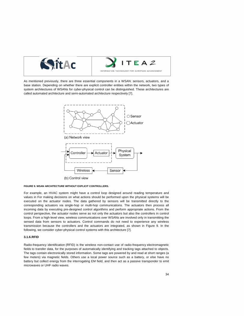
34
As mentioned previously, there are three essential components in a WSAN: sensors, actuators, and a
base station. Depending on whether there are explicit controller entities within the network, two types of
system architectures of WSANs for cyber-physical control can be distinguished. These architectures are
called automated architecture and semi-automated architecture respectively [7].
FIGURE 9. WSAN ARCHITECTURE WITHOUT EXPLICIT CONTROLLERS.
For example, an HVAC system might have a control loop designed around reading temperature and
values in For making decisions on what actions should be performed upon the physical systems will be
executed on the actuator nodes. The data gathered by sensors will be transmitted directly to the
corresponding actuators via single-hop or multi-hop communications. The actuators then process all
incoming data by executing pre-designed control algorithms and perform appropriate actions. From the
control perspective, the actuator nodes serve as not only the actuators but also the controllers in control
loops. From a high-level view, wireless communications over WSANs are involved only in transmitting the
sensed data from sensors to actuators. Control commands do not need to experience any wireless
transmission because the controllers and the actuators are integrated, as shown in Figure 9. In the
following, we consider cyber-physical control systems with this architecture [7].
3.1.6. RFID
Radio-frequency identification (RFID) is the wireless non-contact use of radio-frequency electromagnetic
fields to transfer data, for the purposes of automatically identifying and tracking tags attached to objects.
The tags contain electronically stored information. Some tags are powered by and read at short ranges (a
few meters) via magnetic fields. Others use a local power source such as a battery, or else have no
battery but collect energy from the interrogating EM field, and then act as a passive transponder to emit
microwaves or UHF radio waves.

35
The term of RFID encompasses different kinds of technologies. They can be distinguished by their
capability of reading distance and the induced applications. Realization of IoT paradigm depends on
integration of RFID systems (tracing and addressing items non-contact and automatically).
RFID tags could be used for identification of objects with reading distance which can reach 7 to 8 meters.
These tags can work with an important variety of frequency: 135 kHz, 13.56 MHz, 433 MHz, 860 to 950
MHz, 2.45 GHz and 5.8 GHz.
In an IoT scenario, there would be billions of devices that could be addressable and could be connected
to IP-based networks. RFID identified as an important identification technology with communication
capabilities. Because of its low power consumption in case of active tag and passive tag, large-scale
deployment drives it to enable on IoT environments.
3.2. Network Technologies
This section describes the various networking approaches that provide communication capabilities to the
different nodes detailed above.
3.2.1. ZigBee
ZigBee as a trademark of ZigBee Alliance is Network Layer (OSI layer 3) protocol facilitating energy
efficient wireless mesh networking features on top of IEEE 802.15.4 which is a standard addressing OSI
Layer 1 and 2 for devices with constrained resources such as energy and processing. ZigBee
specifications which are created and maintained by ZigBee Alliance are as follows [8];
• ZigBee Specification is the basis for energy-efficient mesh networking but also provides a
security layer and an application framework. ZigBee specification provides these features
under two feature sets;
o ZigBee PRO
o ZigBee
While ZigBee PRO is the mostly used implementation among developers, both implementations are
designed to interoperate with each other. The main difference between two specifications is the size of
the network; ZigBee PRO is capable of supporting larger networks of thousands of devices whereas
ZigBee supports smaller networks of hundred devices. For both ZigBee and ZigBee PRO feature sets,
the compatibility tests and certification of devices are conducted by ZigBee Alliance.
• ZigBee IP Specification defines IPv6 for wireless sensor network on top of IEEE 802.154. It is
an open standard-based specification aiming seamless internet connection of constrained
devices via standard internet protocols such as TCP, UDP, 6LowPAN, PANA but without the
need of intermediate gateways.
• ZigBee RF4CE Specification provides a simplified network stack with bi-directional device-to-
device communication features. Just like the other two specification, RF4CE specification
also defines a network layer on top of IEEE 802.15.4 but narrowing the target field of
application to simple control applications where full-featured mesh networking is not
necessary. Therefore, RF4CE specification provides a less complex implementation yielding
lower memory and cost requirements.

36
Beyond these three specifications ZigBee Alliance also defines application profiles so called ZigBee
Standards which provide customized ZigBee stack for specific application domains which also helps
device manufactures to focus more on business needs. The list of these standards and the specification
that supports these standards is shown in Table 1 [9]:
TABLE 1. ZIGBEE SPECIFICATIONS AND STANDARDS.
4. ZigBee Specification ZigBee IP Specification ZigBee RF4CE
Specification
Building Automation ✓
Remote Control ✓
Smart Energy ✓
Smart Energy v2 ✓
Health Care ✓
Home Automation ✓
Input Device ✓
Light Link ✓
Retail Services ✓
Telecom Services ✓
As stated before, ZigBee provides the connectivity of ZigBee nodes by constituting a mesh network so
that the output power requirement and the cost of ZigBee devices are lower than WiFi, Even though both
WiFi and ZigBee operates on the same ISM band and for an home area network (HAN) the coexistence
of these two technology is a common situation, channel variation and the CSMA-CA protocol defined
within IEEE 802.15.4 provide robust network connectivity in the coexistence of WiFi devices and other
ZigBee devices. On the other hand to satisfy the goal of being low power and low cost, most of the time
not only the output power but also the processing and memory capacity of devices are constrained, which
has to be taken into account depending on the application specific purposes. For example, in an home
automation use case, using ZigBee for the control of battery powered and low cost devices such as
thermostats and switches may be a better choice however for white appliances having AC power
supplies, built-in control units and circuitry, it may not be the optimum solution.
From the technical specification’s point of view the three ZigBee specifications have a lot in common;
however there are also some differences which are summarized in the table below.

37
TABLE 2. ZIGBEE TECHNICAL SPECIFICATIONS.
5. ZigBee Specification ZigBee IP Specification ZigBee RF4CE Specification
Physical
Radio
IEEE 802.15.4 IEEE 802.15.4 IEEE 802.15.4
Operating
Frequency
2.4 GHz plus 915MHz
Americas, 868 MHz
Europe
2.4 GHz plus 915MHz
Americas, 868 MHz
Europe and 920 MHz
Japan
2.4 GHz plus 915MHz
Americas, 868 MHz Europe
Number of
Channels
16 channels @ 2.4GHz
10 channels @
915MHz
1 channel @ 868MHz
16 channels @ 2.4GHz
10 channels @ 915MHz
1 channel @ 868MHz
3 channels @2.4GHz
Channels: 15, 20, 25
Raw Data
Throughput
250Kbp @ 2.4GHz
40Kbp @915MHz
20Kbs @868MHz
250Kbp @ 2.4GHz
40Kbp @915MHz
20Kbs @868MHz
250Kbp @ 2.4GHz
Transmission
Range
10-100m (depends on
power output and
environmental
characteristics)
50-200m (depends on
power output and
environmental
characteristics)
10-100m (depends on power
output and environmental
characteristics)
Security AES128 Encryption/
Authentication/ Trust
Centers
AES-128-CCM @ link
layer
TLS v1.2 @ application
layer
PANA/EAP for
authentication
128-bit AES-CCM
128-bit link keys

38
Topology
ZigBee Coordinator
ZigBee Router
ZigBee End Device
internet
ZigBee IP Border Router
ZigBee IP Coordinator
ZigBee IP Router
ZigBee IP Hosts
6.
ZigBee RF4CE Controller
ZigBee RF4CE Target
6.1. Scalabilit
y
6.2. 64.000 nodes per
network
6.3. No explicit limitation
6.3.1. IPv6 over Low Power Wireless Personal Area Network (6LowPAN)
Since the concept of wireless sensor and actuator networks came into view, many protocols and
standards have been defined regarding to machine to machine communication of constrained devices.
However most of the focus of these studies is on the protocol efficiency within the network constituted by
these constrained devices. Interfacing these devices to the outer world is the responsibility of gateway
hardware and/or software. As the concept of internet of things comes up, the machine to machine
communication turned into machine to cloud communication, and this brought the necessity of a more
standard mechanism to interface these constrained devices to the internet. While the existing IPv6
infrastructure with its upper layer protocol support, existing know-how and tools is a good candidate to
connect billions of things, it has never been designed by concerning constrained devices.
Having these requirements, IETF (Internet Engineering Task Force) which is an organization defining
standards of the internet, proposed a set of standards; RFC4944 (2007), RFC6282 (2011), RFC6775
(2012) so called 6loWPAN to enable IPv6 routing over low power personal area networks and more
specifically over 802.15.4 networks, typically having the following architecture (see Figure 10);
Commentaire [ED2]: No content in this row

39
FIGURE 10. 6LOWPAN ARCHITECTURE
As depicted in Figure 11Erreur ! Source du renvoi introuvable., the most important layer in the
6LoWPAN stack is the adaptation layer which is sitting on top of MAC layer. Among many others, the
most significant functionalities addressed within this layer are;
● Header Compression: The header overhead of IP and other upper layer protocols such as UDP,
TCP is large. More specifically:
25 bytes for 802.15.4 maximum frame overhead
21 bytes for link layer security
40 bytes for IP header
8 bytes for UDP header
Since 802.15.4 has a maximum transmission unit (MTU) of 127 bytes, only 33 bytes left for actual
data and it gets even smaller if TCP is used (20 bytes for TCP header). To resolve this issue the
adaptation layer facilitates a header compression mechanism which compresses the IP address
and upper protocol headers.
● Packet fragmentation and reassembling: IPv6 packets with an MTU of 1280 bytes are too large to
fit in 802.15.4 packets. The adaptation layer specifies a fragmentation and a flow control
mechanism to overcome this issue.
● Routing: The routing mechanism of 6LoWPAN stack is defined under two cases;

40
○ Mesh Under: routing of packets in LoWPAN. Routing operations such as packet
forwarding, path calculation takes place in adaptation layer. There are several routing
protocols defined for mesh-under routing such as; Hi-Low, Extended Hi-Low, LOAD,
MLOAD, DYMO-Low.
○ Route Over: routing of packets in between IPv6 domain and LoWPAN domain. Routing
operations take place in IPv6 layer.
FIGURE 11. PROTOCOL STACK
As stated above, 6LoWPAN is designed to provide IP capability to constrained devices, therefore the
following domains; Home & Building automation, physical security, environment monitoring are all good
use cases for 6LoWPAN applications just like ZigBee. On the other hand 6LoWPAN does not specify
application profiles unlike ZigBee. This was used to be evaluated as a down side; one can easily come
across few years old journals and studies on which ZigBee and 6LoWPAN are considered competitors.
However, today they are more like complement of each other and this becomes more obvious after the
ZigBee Alliance announced the new ZigBee IP specification for smart energy profile (SEP2) based on the
6LoWPAN.
6.3.2. Bluetooth
Bluetooth is a set of specifications providing wireless connectivity for electronic devices and peripherals. It
is mainly designed for low data rate, low cost, low energy consumption and short range communication.
Bluetooth technology was first developed by Ericsson researchers in 1994. Today, maintained by
Bluetooth Special Interest Group (SIG) which was founded by Ericsson, IBM, Intel, Nokia and Toshiba in
1998, since that time there are several specifications published [11]:
● Core version 2.0 + Enhanced Data Rate (EDR), 2004
● Core version 2.1 + EDR, 2007
● Core Specification Addendum (CAS) 1, 2008

41
● Core version 3.0 + HS, 2009
● Core version 4.0, 2010
● Core Specification Addendum (CAS) 2, 2011
● Core Specification Addendum (CAS) 3, 2012
● Core Specification Addendum (CAS) 4, 2013
● Core version 4.1, 2013
The technology was also standardized as IEEE 802.15.1 by IEEE 802.15 WPAN Task Group 1 in 2002
[12] and 2005 [13]. Among these specifications, version 4.0 has to be explained in more detail; this is
because the specification introduced a new protocol stack which is called Bluetooth Low Energy (BLE) for
low energy applications besides the classical Bluetooth (v1.0 to v3.0). One of the significant differences
between BLE and the classic Bluetooth is that, BLE is not backward compatible with the previous
specifications. However, specification allows implementing either or both of the protocols and the devices
which implement both are capable of communicating with both the classical Bluetooth and Bluetooth Low
Energy devices. These dual-mode devices are branded as Bluetooth SMART Ready and devices
implementing only BLE stack are branded as Bluetooth SMART.
Classic Bluetooth device network is composed of at least 1 master device and 1 (up to 7) slave device(s)
and it is called piconet. The communication is initiated by the master device but once the connection the
roles may change as requested by slave(s). Slave devices do not communicate with each other directly
but over the master device. So that each piconet needs and may have only one master device, on the
other hand slave devices can be members of different piconets which form the topology called
scatternets.
6.3.3. Near Field Communication
Near Field Communication (NFC) technology allows a simpler way to make payments, pair/connect
devices or exchange content just with proximity contact. A standards-based connectivity technology, NFC
harmonizes today's diverse contactless technologies, enabling solutions in areas such as: Access control,
consumer electronics, Healthcare, Information collection and Exchange, Loyalty and coupons, Payments
or Transport. NFC-Forum promotes the use of NFC short-range, was founded in 2004 by Nokia, Philips
and Sony, and now has more than 160 members. The Forum also promotes NFC and certifies device
compliance. NFC standards cover communications protocols and data exchange formats, and are based
on existing radio-frequency identification (RFID) standards including ISO/IEC 14443 and FeliCa.
Structurally, NFC Forum specifications are based on existing radio-frequency identification (RFID) and
recognized standards like ISO/IEC 18092 and ISO/IEC 14443-2,3,4, as well as JIS X6319-4. NFC
structure is shown in Figure 12.

42
FIGURE 12. NFC STRUCTURE
NFC provides a range of benefits to consumers and businesses, such as:
Intuitive: NFC interactions require no more than a simple touch
Versatile: NFC is ideally suited to the broadest range of industries, environments, and uses
Open and standards-based: The underlying layers of NFC technology follow universally
implemented ISO, ECMA, and ETSI standards
Technology-enabling: NFC facilitates fast and simple setup of wireless technologies, such as
Bluetooth and Wi-Fi.
Inherently secure: NFC transmissions are short range (from a touch to a few centimeters)
Interoperable: NFC works with existing contactless card technologies
Security-ready: NFC has built-in capabilities to support secure applications
6.3.4. Radio Frequency ID
RFID is a contactless system for wireless communication which uses frequency bands as shown in Table
5.2. This technology uses electromagnetic fields to transfer data between a passive component and a
device or between enabled devices, for example mobile phones.
Passive tags require no battery, there are powered by the electromagnetic field used to read them. RFID
tags can be attached to any kind of objects (e.g. cloths, wallets, cars) or devices (e.g. mobile phones,
tablets.), enabling the possibility of reading personally linked information.

43
These are some examples of use cases: commerce, product tracking, telemetry, transportation payments,
animal identification, access control or advertising. Main problems around the RFID technology are: data
flooding, global standardization, privacy or XMPP temperature exposure.
TABLE 3.COMMON RFID FREQUENCY BANDS.
7. Band 8. Regulations 9. Range 10. Data
speed
11. Remarks 12. Approximate
tag cost
(USD) in
volume
(2006)
13. 120-150 kHz
(LF)
14. Unregulated 15. 10 cm 16. Low 17. Animal
identification
, factory
data
collection
18. $1
19. 13.56 MHz
(HF)
20. ISM band
worldwide
21. 1 m 22. Low to
moderate
23. Smart cards 24. $0.50
25. 433 MHz
(UHF)
26. Short Range
Devices
27. 1-100
m
28. Moderate 29. Defense
applications,
with active
tags
30. $5
31. 868-870
MHz
(Europe)
902-928 MHz
(North America)
UHF
ISM band 1-2 m Moderate to
high
EAN, various
standards
$0.15 (passive
tags)
2450-5800 MHz
(microwave)
ISM band 1-2 m High 802.11 WLAN,
Bluetooth
standards
$25
(active tags)
3.1-10 GHz
(microwave)
Ultra wide band to 200 m High Requires semi-
active or active
tags
$5 projected
Standards that have been made regarding RFID technology include:
ISO 14223 – Radiofrequency identification of animals – Advanced transponders
ISO/IEC 14443: This standard is a popular HF (13.56 MHz) standard for HighFIDs, which is being
used as the basis of RFID-enabled passports under ICAO 9303. The Near Field Communication
standard that let’s mobile devices act as RFID readers/transponders is also based on ISO/IEC
14443.

44
ISO/IEC 15693: This is also a popular HF (13.56 MHz) standard for HighFIDs widely used for
non-contact smart payment and credit cards.
ISO/IEC 18000: Information technology—Radio frequency identification for item management:
Part 1: Reference architecture and definition of parameters to be standardized
Part 2: Parameters for air interface communications below 135 kHz
Part 3: Parameters for air interface communications at 13.56 MHz
Part 4: Parameters for air interface communications at 2.45 GHz
Part 6: Parameters for air interface communications at 860–960 MHz
Part 7: Parameters for active air interface communications at 433 MHz
ISO/IEC 18092 Information technology—Telecommunications and information exchange between
systems—Near Field Communication—Interface and Protocol (NFCIP-1)
ISO 18185: This is the industry standard for electronic seals or "e-seals" for tracking cargo
containers using the 433 MHz and 2.4 GHz frequencies.
ISO/IEC 21481 Information technology—Telecommunications and information exchange between
systems—Near Field Communication Interface and Protocol -2 (NFCIP-2)
ASTM D7434, Standard Test Method for Determining the Performance of Passive Radio
Frequency Identification (RFID) Transponders on Palletized or Unitized Loads
ASTM D7435, Standard Test Method for Determining the Performance of Passive Radio
Frequency Identification (RFID) Transponders on Loaded Containers
ASTM D7580 Standard Test Method for Rotary Stretch Wrapper Method for Determining the
Readability of Passive RFID Transponders on Homogenous Palletized or Unitized Loads
In order to ensure global interoperability of products several organizations have setup additional
standards for RFID testing. These standards include conformance, performance and interoperability tests.
Groups concerned with standardization are:
DASH7 Alliance: international industry group formed in 2009 to promote standards and
interoperability among extensions to ISO/IEC 18000-7 technologies
EPCglobal – this is the standardization framework that is most likely to undergo International
Standardizations according to ISO rules as with all sound standards in the world, unless residing with
limited scope, as customs regulations, air-traffic regulations and others. Currently the big distributors and
governmental customers are pushing EPC heavily as a standard well accepted in their community, but
not yet regarded as for salvation to the rest of the world.

45
31.1.1. LTE: Low cost-M2M and the proposed D2D architecture
31.1.1.1. The LTE access technology
LTE is a cellular wireless access technology developed for wideband data access, ubiquitous coverage
and universal access. Enhancements have been provided and, unquestionably, enhanced LTE identified
as LTE Advanced (LTE-A) will be the leading global 4G standard fulfilling the defined ITU-R requirements
[18] on IMT-Advanced identified as the peak data rates beyond 1Gbps. While further enhancements to
LTE-Advanced have just been completed in 3GPP Release 11, the new technology trends become visible
to serve the continuously growing traffic demand.
There are new key technologies that the LTE Release 12 will address. These are: Small Cell
Enhancements, a New Carrier Type, 3D-MIMO Beamforming, Machine-Type-Communication, LTE-WiFi
Integration at radio level and Public Safety incl. Device-to-Device communication. The completion of
Release 12 is expected for the mid of 2014 and deployments might be seen around the end of 2015 and
later. This section will present in detail some of the key technologies addressed by the LTE R12 and what
can be its evolution, R13 and R14/ R15. For this project, the Machine type communication is what is on
our interest.
31.1.1.2. The new LTE Releases
Standardization work and release timing in 3GPP used to be splited into three stages. The Stage 1 for
Requirements and Service Aspects, Stage 2 for Architecture and Technical Design and Stage 3 for
Detailed Specifications. For the Release 12 the Stage-1 work started in 2011. Nevertheless in the radio
groups little time was spent on it due to a 3 month delay of Release 11 completion. The following are the
official completion dates of Release 12 as of today:
● Stage 1: March 2013 RAN
● Stage 2: December 2013 RAN
● Stage 3: June 2014 RAN
● ASN.1 freeze likely in September 2014
First products should not be expected sooner than 15 to 18 months after ASN.1 freeze. Therefore actual
deployment could be expected end of 2015 and later.
At 3GPP RAN Plenary#58 in December 2012 in Barcelona [15] major decisions concerning the content of
Release 12 where made where respective decisions were made respective to the Release 12. In this
section we summarize the technology proposals and explained in relative detail, most taken from [16].
Surely the content and timing of Release 13 will depend on progress in Release 12.
It can be deduced there will be another release to further enhance LTE-A technology, a Release 13.
Dates of Release 13 are still hypothetical and not official, yet. Planning are to Start on June 2014 for RAN
and Completion for December 2015

46
The timing of Release 14/15 is likely to be influenced by the World Radio Conference (WRC) 2015
scheduled to take place in September 2015. Potential candidate bands allocated at WRC 2015 might
include the bands 1427-1525 MHz, 3.4-3.6 GHz and 3800-4200 MHz
As consequence a completely new access technology might be defined in the Rel.14/15 time frame for
commercial deployment at the end of this decade. Up to today most companies call this technology
Beyond 4G.
31.1.1.3. Low Cost Machine Type Communication
A massive growth of Machine to Machine (M2M) communication, devices and traffic is expected to
support smart grid, transport, logistics, e-health, energy, safety applications etc. Therefore the LTE radio
interface shall be prepared to efficiently support the massive transfer of small, infrequent packets using
very low cost, low complexity and low power devices. Quite some work on Machine Type Communication
(MTC) was already standardized in Release 11. The work covers service requirements, architecture and
security issues. Among others, a MTC Interworking Function and Service Capability Server [17] are
defined in Release 11. Significant link budget enhancements are targeted in this work to improve indoor
penetration. The use case is that some MTC UEs are installed in the basements of residential buildings or
locations shielded by foil-backed insulation, metalized windows or traditional thick-walled building
construction, and these UEs would experience significantly greater penetration losses on the radio
interface than normal LTE devices. Most promising and simple techniques are around adding time
diversity (e.g. TTI bundling), extensive use of HARQ repetition as well as power boosting.
31.1.1.4. LTE Device to Device Communication architecture
Device to device communication allows direct communication between UEs that are in proximity to each
other. Besides its potential to save energy, reduce interference and extend coverage, the key driver for
this work is to ensure that 3GPP LTE meets the needs of Public Safety. Until today different technologies
are used for public cellular networks and for dedicated public safety networks. LTE is already globally
promoted as future public safety system.
Once D2D is standardized the market might also see new proximity-based applications and services
[18][18]. Focus is mostly given to network controlled D2D communication as shown in Figure 13. In this
case, the control signaling (e.g. initial access, authentication, connection control) as well as resource
reservation is handled by the network

47
FIGURE 13. THE LTE NETWORK CONTROLLED DEVICE TO DEVICE COMMUNICATION.
This way Quality of Service can be guaranteed and the network operator still remains in control of the
transmission. Although standardization did not start yet, it can be assumed that schemes that are
transparent to the user equipment will be preferred. Although not shown in Figure 1, it is also likely that a
radio bearer for potential data transmission to the network is being maintained all the time.
The Radio Resource Control System Information might require that a new specification also supports an
autonomous control by the UEs or a hybrid approach with a distributed control between network and UEs.
31.2. Resource modeling
The use of different sensors in one system leads to architectural and language incompatibilities making
them expensive and difficult to maintain and extend. This is because specific proprietary software is
traditionally designed for each sensor. Therefore, the integration of a system is major concern which
usually requires from developing complex and redundant software code, which in many cases turns to be
inefficient.
Moreover, the data gathered from different sensors is liable to be in different formats hindering the
management and processing of the information. Proper storage and access is also an important activity
when needing to manage large volumes of information.
To alleviate or even eliminate those problems, several sensor system modeling techniques have been
developed.
This section includes a review of the most relevant techniques to this matter that has been proposed in
the last decades analyzing their characteristics according to SITAC project requirements.
Within SITAC concept, any resource: sensor, actuator, device, user or process is treated in the same way
and as a part of a social network. According to that, a common standard for the definition and modeling of
resources (either devices or users) is required, allowing an easy and full integration of any of them in the
SITAC platform without special requirements to higher levels of abstraction due to their nature.
31.2.1. AMON
48
AMON [19] is a standard developed by AMEE UK Limited with the assistance of expert companies in the
metering/monitoring device industry; it defines an appropriate data format to describe the exchange of
measurement data and device monitoring. It is an open source, released under Creative Commons
Attribution 2.0 UK: England & Wales License.
AMON’s objectives are: to be appropriate for the description and exchange of measuring and monitoring
device data; to be human readable and self-documenting, to be widely supported, bandwidth sensitive,
simple, extensible and easily support new types of data.
AMON data format defines a number of commonly used data fields for devices (such as the device name,
its location etc.), and a number of commonly used data fields for device readings. This ensures that the
data format is suitable for the description and exchange of metering/monitoring device data and is simple
to use. Moreover, it uses JSON encoding which ensures that the data format balances the need to be
human readable and self-documenting against the need to be bandwidth sensitive. Additionally, as other
languages that have library support for JSON encoding, AMON is widely supported. Finally, although the
data format does define commonly used data fields for devices and device readings, it does not exclude
the use of custom device data or reading data. These can be described and exchanged using the AMON
data format without modification to the data format, ensuring that the format is extensible.
Therefore, AMON provides a quick and efficient data exchange from both device and their
measurements. It can be complemented with Storage platform for metering/monitoring device and a
RESTful. However, it lacks dictionaries to assist and facilitate the modeling and the introduction of
processes to the system.
31.2.2. Device Kit
The Device Kit [20] is OSGi based technology that uses XML language and that enables the development
of applications for devices when the information about the hardware is unknown. It uses the publication
and subscription methods, thus, an application subscribes to a service and it is notified when an event is
published.
31.2.3. EDDL
Electronic Device Description Language (EDDL) was originally developed by the University of Florida and
currently standardized under the IEC 61804-3 [21]. It supports device integration, including sensors and
actuators. EDDL assumes that devices have no networking capabilities and are connected to
applications via sensor platform, thus, it is just focused on device to device connections.
31.2.4. ECHONET
ECHONET (the Energy Conservation and Home care Network) standard is a Japanese initiative that
started in 1997 which specifies and open system architecture that enables the integration of a variety of
home appliances and sensors [22]. It supports basically energy consumption monitoring and
management and allows networked applications and services to access and control home appliances. It
provides a definition of properties and access methods to devices, however, it requires vendors to create
the same interface in their devices and it is not suitable for scalable systems.

49
31.2.5. IEEE 1451
The IEEE 1451 [23], [24], a family of Smart Transducer Interface Standards, describes a set of open
common network-independent communication interfaces in TDL (template description language) for
connecting transducers (sensors or actuators) to communication networks and processors. The key
feature of these standards is the definition of a TEDS (Transducer Electronic Data Sheet). The TEDS is a
memory device attached to the transducer, which stores transducer identification, calibration, correction
data, and manufacture-related information. The goal of 1451 is to allow the access of transducer data
through a common set of interfaces whether the transducers are connected to systems or networks via a
wired or wireless means. The family of IEEE 1451 standards is sponsored by the IEEE Instrumentation
and Measurement Society’s Sensor Technology Technical Committee.
31.2.6. FlowTalk
FlowTalk [26] is an object-oriented programming language. It is designed to develop easily software for
embedded wireless sensor devices. It adapts the models that usually come from using sensors with
controlled disruption and light-weight continuation mechanism. The model converts asynchronous long-
latency operations into synchronous and blocking method calls. In addition, Built for TinyOS, FlowTalk
exchanges dynamism for a reduction in memory consumption.
31.2.7. Ptolemy
The Ptolemy Project [26] studies the modeling, simulation and design of embedded real-time concurrent
systems. The basic objective is the assembly of concurrent components. Its principle is the use of well-
defined models of computation. These models govern the interaction between components. The use of
heterogeneous mixtures of models of computation is proposed.
A software system called Ptolemy II is being constructed in Java. The work is conducted in the Center for
Hybrid and Embedded Software Systems (CHESS) in the Department of Electrical Engineering and
Computer Sciences of the University of California at Berkeley.
31.2.8. SensorML
Sensor Model Language (SensorML) [27], is a standard of the Open Geospatial Consortium (OGC) which
provides standard formats and models in Extensible Markup Language (XML) to describe sensors and
measurement processes. It can be used to describe a wide range of sensors including both static or
dynamic platforms and both remote or in-situ sensors.
SensorML is defined and built on common data definitions that are used throughout the OCG Sensor
Web Enablement (SWE) framework. Although it does not depend upon the presence of the other SWE
components, it can be complemented by the use of other SWE techniques and tools, such as
Observations and Measurements (O&M), Transducer Markup Language (TML), Sensor Observation
Service (SOS), Sensor Planning Service (SPS), Sensor Alert Service (SAS), Web Notification Service
(WNS) and TML which are described below.
Therefore, it provides a common framework for any process and process chain but it is particularly well-
suited, but not exclusively intended, for the description of sensors, systems and the processing of sensor

50
observations. Specifically, it provides the required information for sensor discovery, geolocation,
programming, alert subscription and support for on-demand processing of the observations.
According to this standard, every device or component can be modeled as a “Process”. Processes are
entities that take inputs and through the application of well-defined methods using specific parameters,
results in outputs. Additionally, they provide relevant metadata.
These processes are classified according to their nature into two groups, physical and non-physical
process. Among those considered as physical processes, we can found transducers, actuators and
processors that are treated as “Process Components1” and sensors and platforms that are modeled as
“Systems2”. Among those considered as non-physical processes, we have “Process Models
3” that provide
executable process description of processes and “Process Chains4”. In addition, “Process Methods”
provide relevant pieces of information for validating and enabling the execution of individual atomic
processes (either process components or process models).
Thanks to the SensorML definition, a quick and efficient data exchange from any type of device,
component, entity or system is achieved. It also provides efficient management of device observations
taking care of their sampling and processing. Thus, this standard is suitable for the definition of any kind
of resource independently of its nature and includes predefined dictionaries to ease the addition of new
“processes” to the system.
It is important to highlight that SensorML describe measurement processes but it does not encode the
data coming from those measurements. Therefore, to achieve a complete model of the system,
measurements need to be represented by other methods. The tandem SensorML/O&M is the most
versatile and widely used.
31.2.8.1. O&M
Observations and Measurements (O&M) [28], ISO 19156 standard defines an XML implementation of the
conceptual models for describing observations and sampling features.
An observation has a single and observable procedure and a single result. The description of the
procedure provides important metadata to support the interpretation of the result. If it is a sensor, then it
may be a “sensor package” measuring an “aggregate observable” and producing a resulting “aggregate
value”. But when associated with an observation, the sensor, the observable and the result are single
logical entities.
1 Atomic physical process that transforms information from one form to another.
2 Components physical model consisting of a group of physical process.
3 Atomic non-physical blocks of processing.
4 No-physical compound modeling blocks, composed of interconnected threads that can be both models and chain
processes.

51
Thus, it is through its association with an observation feature that a value is bound to a feature of interest
or a geospatial location, to a time instant or period and to the sensor instance responsible for that
observation.
31.2.8.2. TML
Transducer Markup Language (TransducerML or TML) [29] is a standard developed by OGC. It defines a
set of models describing the hardware response characteristics of a transducer and an efficient method
for transporting sensor data and preparing it for fusion through spatial and temporal associations. It
basically provides a conceptual approach and XML schema to support real-time transmission of data and
sensor systems.
TML is capable of precise time-tagging of data, so that it is possible to know precisely when a physical
phenomenon was measured at the individual measurement level, and also captures latency or delay
information at a fine resolution. This enables the precise determination of when a data point was taken,
as well as aiding in interpolation between data points and the reconstruction of events.
31.2.9. ThingML
ThingML [30] is a modeling language for embedded and distributed systems. It is proprietary language
developed by the Networked Systems and Services department of SINTEF in Oslo, Norway. It is focused
on models for embedded systems with limited resources such as sensors or microcontroller-based
devices.
ThingML has been developed as a domain-specific modeling language. It includes concepts to describe
software components and communication protocols. The formalism used is a combination of architecture
models, state machines and language. Also, ThingML includes tools such as text editors to create and
edit ThingML models and code generators to compile ThingML to C, Java and Scala.
TABLE 4. RESOURCE MODELING COMPARATIVE TABLE

AMON DEVICE KIT EDDL ECHONET
DESCRIPTION Appropriate data format to
describe the exchange of
measurement data and device
monitoring.
OSGi based technology
for the description of
devices
Description language for
device integration
Open system
architecture for the
integration of devices
LANGUAGE USED JSON XML ------ ------
APPLICATION ------ Development of
applications for devices
Device to device
connection
Home appliances and
sensor integration
FEATURES Quick and efficient data
exchange
Description of devices
when the HW is
unknown
Service-oriented.
Assumes no networking
capabilities for devices
Definition of interface
(properties and access
methods). Requires
vendors to include the
interface in the device
TOOLS Storage platform for
metering/monitoring and a
RESTful
Publication and
subscription methods
------ ------

IEEE 1451 FLOWTALK PTOLEMY SENSORML THINGML
DESCRIPTION Set of open
common network-
independent
communication
interfaces
Software
development
language for
embedded
wireless
sensors
devices.
Software
system for
design of
concurrent
embedded real-
time system.
Standard for modelling,
observation and
measurement of devices.
Language for
modelling
embedded and
distributed system
such as sensors
and
microcontrollers
devices.
LANGUAGE
USED
TDL FlowTalk Java XML ThingML
APPLICATION Connection of
devices to
networks or
processors
Built for
TinyOS.
Still under
development.
Description of any kind of
resources (devices,
entities, processes, etc)
Embedded
systems with
limited resources.
FEATURES Inclusion of TEDs Low memory
consumption.
------ Quick and efficient data
exchange. Importance of
sampling and processing.
Easy incorporation of new
processes to the system.
Proprietary
solution.
Combined
formalism of
architecture
models, state
machines and
language

54
TOOLS TEDs ------ ------ Additional techniques and
tools: O&M, TML, etc. and
predefined dictionaries.
Text editors and
code generators
to C, Java and
Scala
Conclusion
The variety of devices that conforms the IoT, together with their different characteristics and capabilities,
and the different communication mechanisms that make them interoperate are a key concept when
designing services and applications for IoT. This, together with the addition of Social Networks, and the
inclusion of different users in the loop, significantly augments the complexity of the final system.
This chapter depicts a review of the different technologies that are part of the IoT. First, a revision of the
physical objects: sensors, actuators, and RFID, that can be fixed or mobile, even included in
smartphones, as well as those components such as gateways and repeaters that are part of the
communication infrastructure which is the bridge from the sensors and actuators to the rest of the system.
The current developments regarding networking technologies are also detailed. At present, there exist a
number of communication technologies that enable the orchestration of the different devices to be able to
efficiently gather their data. ZigBee and 6LowPAN represent the new wave in sensor communications,
but other well-known technologies such as Bluetooth and LTE are also considered in order to augment
the communication capabilities of the IoT.
References
[1] http://www.smartsantander.eu/
[2] http://www.libelium.com/products/waspmote/ota/
[3] http://www.libelium.com/products/waspmote-mote-runner-6lowpan/
[4] Nicholas D. Lane, Emiliano Miluzzo, Hong Lu, Daniel Peebles, Tanzeem Choudhury,and Andrew T.
Campbell, Dartmouth College : A survey of mobile phone sensing , Communications Magazine, IEEE , 2010
[5] Ian F. Akyildiz, et al. "Wireless sensor networks: a survey." Computer networks 38.4 (2002): 393-422.
[6] X. Cao, et al. "Control systems designed for wireless sensor and actuator networks." Communications,
2008. ICC'08. IEEE International Conference on. IEEE, 2008.
[7] Xia, Feng, Xiangjie Kong, and Zhenzhen Xu. "Cyber-Physical Control over Wireless Sensor and Actuator
Networks with Packet Loss." Wireless Networking Based Control. Springer New York, 2011. 85-102.
[8] ZigBee Specifications, http://www.zigbee.org/Specifications.aspx
[9] ZigBee Standards, http://www.zigbee.org/Standards/Overview.aspx
[10] G. Mulligan, “The 6LoWPAN architecture,” in Proceedings of the 4th Workshop on Embedded Networked
Sensors (EmNets '07), pp. 78–82, June 2007.
[11] Adopted Bluetooth® Core Specifications, Bluetooth.org.
[12] IEEE Std 802.15.1–2002 – IEEE Standard for Information technology – Telecommunications and information
exchange between systems – Local and metropolitan area networks – Specific requirements Part 15.1: Wireless
Medium Access Control (MAC) and Physical Layer (PHY) Specifications for Wireless Personal Area Networks
(WPANs)".
[13] IEEE Std 802.15.1–2005 – IEEE Standard for Information technology – Telecommunications and information
exchange between systems – Local and metropolitan area networks – Specific requirements Part 15.1: Wireless
Medium Access Control (MAC) and Physical Layer (PHY) Specifications for Wireless Personal Area Networks (W
Pans)".
[14] RWS-120052, Report of 3GPP TSG RAN Workshop on Release 12 and onwards, Ljubljana, Slovenia, June
2012
[15] RP-13xxxx, Draft Report of 3GPP TSG RAN meeting#58, Barcelona, Spain, Dec. 2012
[16] Eiko Seidel, 3GPP LTE-A Standardisation in Release 12 and Beyond, Nomor Research GmbH, Munich,
Germany, January 2013, http://www.nomor.de/home/technology/white-papers/lte-a-rel12-and-beyond

56
[17] 3GPP TS23.682 “Architecture enhancements to facilitate communications with packet data networks and
applications (Release 11)”
[18] RP-121699, Background on “LTE D2D Proximity Services” Study Item proposal
[19] AMEE/AMON standard https://github.com/AMEE/AMON
[20] Chao Chen, Helal, S. “Sifting Through the Jungle of Sensor Standards,” IEEE, vol,:7 , issue 4, pp. 84,88,
Oct-Dec 2008.
[21] http://www.eddl.org/
[22] http://www.echonet.gr.jp/english/
[23] http://grouper.ieee.org/groups/1451/0/body%20frame_files/Family-of-1451_handout.htm
[24] http://standards.ieee.org/develop/regauth/tut/tdl.pdf
[25] Bergel, A.; Harrison, W.; Cahill, V.; Clarke, S., "FlowTalk: Language Support for Long-Latency Operations in
Embedded Devices," Software Engineering, IEEE Transactions on , vol.37, no.4, pp.526,543, July-Aug. 2011
[26] BModeling Event-Based Systems in Ptolemy II: Project Report. EE249: Design of Embedded Systems:
Models, Validation, and Synthesis Fall 2001.
[27] SensorML http://www.opengeospatial.org/standards/sensorml
[28] Observations and Measurements - XML Implementation http://www.opengeospatial.org/standards/om
[29] Transducer Markup Language Implementation Specification http://www.ogcnetwork.net/infomodels/tml
[30] http://thingml.org/
32. Services and Applications
Building an application that used many devices can be seen as been a service composition, while each
device offers one or more services. It is then possible to create an application that calls or requests data,
actions from/to these devices. This approach is similar to SOC (Services Oriented Computing) [1], in
which devices are seen as services, in a so called “Object as a service” paradigm. To be achieved, SOC
needs to have information about each service, and then to compose them.
32.1. Service Creation and Discovery
Service discovery protocols (SDP) [2] are protocols which allow automatic detection of devices and
services offered by these devices on a computer network. Service discovery requires a common
language to allow software agents to make use of one another's services without the need for continuous
user intervention.
There are several SDP protocols such as:
32.1.1. Dynamic Host Configuration Protocol (DHCP)
DHCP [3] is a network protocol used to configure devices that are connected to a network so they can
communicate using the Internet Protocol (IP). The protocol is implemented in a client-server model, in
which DHCP clients request configuration data, such as an IP address, a default route, and one or more
DNS server addresses from a DHCP server. This protocol is for host configuration only. It does not fit
request for a service when the requester does not known the device he is looking for
DHCP uses UDP broadcasts, and configuration is done with a unicast answer.
57
32.1.2. Zeroconf, Bonjour, Avahi
Zeroconf [4] is an IETF standard protocol for host configuration and services requesting. It can resolve
name to address without a central server. Zeroconf has the same role than DHCP and DNS without
having a dedicated server. Based on multicast request, each node builds its own host lists, and answers
requests if they are concerned by the query. Discovering a service is done by altering the request,
changing the name by the service description. Each node offering a service that fits the request will
respond.
Some other protocols are based on the same approach. Bonjour (made by Apple) uses a mDNS
(multicast DNS) and a DNS-SD (DNS Service Discovery) to retrieve hosts and services.
Avahi is an implementation of Zeroconf under Linux and BSD, while Microsoft offers its own solution
named SSDP.
32.1.3. UPnP
UPnP [5] is a set of protocols for the SoHo (Smart office, Home office) that provide the global
configuration and discovery of devices and services inside a small network. Based on IP, it can work
without a DHCP server, as it provides all the steps to auto configure each node, or to join an already set
network. Once connected to the network and able to communicate with other nodes, a UPnP device will
announce its services. This is done through a udp multicast message. This announcement will be
received by all nodes of the multicast network. The description of the service is provided by the node
itself, and can be accessed with an HTTP request.
SSDP, the Simple Service Discovery Protocol, uses these announcements to set a Control point inside
the network, that will collect all announces made by nodes, or send a request on the multicast network to
ask for it.
UPnP has good results, but is limited to small network (as it uses multicast) and is not secure enough to
be use in other conditions.
32.1.4. Service Location Protocol (SLP)
The Service Location Protocol (SLP, srvloc) [6] is a service discovery protocol that allows computers and
other devices to find services in a local area network without prior configuration. SLP has been designed
to scale from small, unmanaged networks to large enterprise networks. It has been defined in RFC 2608
and RFC 3224 as Standards Track document.
SLP is used by devices to announce services on a local network. Each service must have a URL that is
used to locate the service. Additionally it may have an unlimited number of name/value pairs, called
attributes. Each device must always be in one or more scopes. Scopes are simple strings and are used to
group services, comparable to the network neighborhood in other systems. A device cannot see services
that are in different scopes.
SLP has three different roles for devices. A device can also have two or all three roles at the same time.
User Agents (UA) are devices that search for services

58
Service Agents (SA) are devices that announce one or more services
Directory Agents (DA) are devices that cache services. They are used in larger networks to reduce
the amount of traffic and allow SLP to scale
32.1.5. Web Services Dynamic Discovery (WS-Discovery)
WS-Discovery [7] is a technical specification that defines a multicast discovery protocol to locate services
on a local network. As the name suggests, the actual communication between nodes is done using web
services standards, notably SOAP-over-UDP.
The protocol was originally developed by BEA Systems, Canon, Intel, Microsoft, and WebMethods. On
July 1st 2009 it was approved as a standard by OASIS.
A Service Provider can explicitly register a service with a Web Services Registry such as Universal
Description Discovery and Integration (UDDI) or publish additional documents intended to facilitate
discovery such as Web Services Inspection Language (WSIL) documents. The service users or
consumers can search Web Services manually or automatically. The implementation of UDDI servers and
WSIL engines should provide simple search APIs or web-based GUI to help find Web services.
32.1.6. Discovering Services in the Internet of Things
DHCP, ZeroConf or UpnP answer the need of discovering services inside a controlled network, where
everything is under the control of an administrator, secured from external attack, and in a limited zone
where the number of services and nodes is quite stable and limited. The choice made for these protocols
is then coherent with the needs and the ability of each stakeholder.
But regarding the huge size of the Internet of things, with 50 billion devices offering and consuming
services, involved in a great number of applications, dynamically requesting for services, using them and
then moving to another place, the approach of devices announcing their services through multicasts
messages is not scalable.
The solution of a central server storing all services offered everywhere, by every device, is also an issue:
Who has the right to store services description? According to which model? How to request for a specific
service, without being overwhelmed by multiple answers?
Service discovering in very large networks needs to be restricted to a limited part of the overall offer. This
“Context aware” limitation can be based on the user, his devices and the public devices accessible from
the place he is located at the moment.
The use of messaging protocol can solve this issue, because it is user-oriented, and it offers some
mechanisms that can be used for the dynamicity of context change (presence information for example).
32.1.6.1. Extensible Messaging and Presence Protocol (XMPP)
XMPP [8] is a communication protocol for message-oriented middleware based on XML (Extensible
Markup Language). The protocol was originally named Jabber, and was developed by the Jabber open-
source community in 1999 for near real-time, instant messaging (IM), presence information, and contact
59
list maintenance. Designed to be extensible, the protocol has also been used for publish-subscribe
systems, signaling for VoIP, video, file transfer, gaming, Internet of Things applications such as the
smart grid, and social networking services.
Unlike most instant messaging protocols, XMPP is defined in an open standard and uses an open
systems approach of development and application, by which anyone may implement an XMPP service
and interoperate with other organizations' implementations. Because XMPP is an open protocol,
implementations can be developed using any software license; although many server, client, and library
implementations are distributed as free and open-source software, numerous freeware and commercial
software implementations also exist.
32.2. Service Composition
Service compositions [9] can be defined as the way a set of single services can be linked to produce as a
result a new service. More technically, such compositions are defined as the process of coordinating an
exchange of information through service interactions. However, depending on how this coordination is
performed we refer to service orchestration (when the coordination is performed by a central entity,
usually a workflow engine) or service choreography (when there is not a central entity managing such
coordination). The main differences between these two types of compositions lie in their executability and
control. For example, the existence of a central entity in service orchestrations ensures that every single
task is been executed properly and it also avoids the exchange of multiple messages as it is required in
service choreographies. In fact, service choreographies are defined by protocols which define legal peer-
to-peer interactions, i.e., message exchanges between two partners. There are different languages to
represent both, service orchestrations and choreographies.
Examples of orchestration languages are BPEL (Business Process Execution Language) and its
extensions to consider humans in the orchestration (BPEL4People and WS-Human Task), BPMN 2.0
(Business process Model and Notation), Orc (academic language built at the University of Texas), YAWL
(Yet Another Workflow Language, a language inspired in Petri-Nets), EPC (Event-driven Process Chain,
a language based on graphs).
On the other hand, examples of choreography languages are the W3C specifications WS-CDL (Web
Service Choreography Description Language) and WSCI (Web Service Choreography Interface (WSCI),
academic initiatives such as BPEL4Chor (a BPEL extension to support service choreographies) or Let’s
Dance (a generic description of requirements for languages to support service interactions) and BPMN
2.0, a specification from the OMG which includes diagrams to represent service choreographies.
In addition to these two ways of creating service compositions, a more light way of composing services
are mashups. Mashups allow connecting open APIs and data sources to produce enriched results that
were not necessarily the original reason for producing the raw source data. Examples of tools allowing
the construction of mashups are Pipes by Yahoo or Deri Pipes.
All these languages can be used to compose any service that is exposed in the Internet to produce as a
result a new service with an added value.
32.3. Services & Applications

60
During last years, the adoption of Web2.0 and IoT related technologies, lead to an explosion of public
applications and services available. Some of these services are designed to help developers to develop
its own composed services or applications easily, providing components such as frameworks, APIs or
standard communication protocols.
Some of these derived services and applications are described below:
32.3.1. Apple Find My Friends
With Find My Friends [10], users can follow people and track where they are at a certain moment. Users
can also share their location with the people they choose. Location is determined using GPS in the iOS
device when Location Services are turned on. Notifications appear when a user requests another user to
see where they are. The feature can be turned on and off at any time. Like many iOS application that use
Location Services, parental controls are available, and the application synchronizes with other
applications with locations, such as Maps and Contacts.
32.3.2. Google Now
Google Now [11] is implemented as an aspect of the Google Search application. It recognizes repeated
actions that a user performs on the device (common locations, repeated calendar appointments, search
queries, etc.) to display more relevant information to the user. The system leverages Google's Knowledge
Graph project, a system used to assemble more detailed search results by analyzing their meaning and
connections. Some examples of information shown to the user are: Events, Mail, Places, Weather, News,
etc.
32.3.3. Waze
Waze [12] is a GPS-based geographical navigation application program for smartphones with GPS
support and display screens which provides turn-by-turn information and user-submitted travel times and
route details, downloading location-dependent information over the mobile telephone network. Waze
differs from traditional GPS navigation software as it is a community-driven application which gathers
some complementary map data and other traffic information from users. Like other GPS software it learns
from users' driving times to provide routing and real-time traffic updates. People can report accidents,
traffic jams, speed and police traps, and can update roads, landmarks, house numbers, etc. Waze also
identifies the cheapest fuel station near a user or along their route.
32.3.4. Amazon Cloud Services
Amazon Web Services (abbreviated AWS) [13] is a collection of remote computing services (also called
web services) that together make up a cloud computing platform, offered over the Internet by Amazon.
Amazon cloud offers different services database or remote storage management, to computation and
network cloud services.
32.3.5. Uber
Uber [14] uses your phone's GPS to detect your location and connects you with the nearest available
driver. The concept behind Uber is: ‘Get picked up anywhere - even if you don't know the exact address’.
61
32.3.6. Gimbal
By creating fully customizable digital boundaries around physical spaces, Gimbal Geofence [15] links with
your customer’s mobile device to create a streamlined, battery optimized system of geographical
awareness, so you can deliver your message when and where it matters most.
With Gimbal Geofence, it is possible to set up the places that matter most to your app and interact with
customers at those locations. Once an individual enters into a geofence you set, you can choose to send
content to their mobile device or simply use that data to further refine offers based on their personal
preferences. When enabled by the end-user, Geofence works in the background even when the app is
closed.
32.3.7. Locale
With Locale [16], you create situations specifying conditions under which your phone's settings should
change. For example, your "At School" situation notices when your Location condition is "77
Massachusetts Ave." and changes your volume setting to vibrate.
Conclusion
One of the main innovation points of the SITAC project is related to the creation of a platform enabling a
diverse group of users to collaboratively create its own services and applications. In order to achieve this
goal, two main areas must be explored: service and application discovery and service composition
technologies. Regarding service discovery, scalability is the key point taking into account the huge
number of potential and heterogeneous services and devices. The utilization of messaging protocols, like
XMPP, will be explored.
Service composition and creation could greatly benefit from existing APIs and services aimed to help
developers with the task of composing and orchestrating applications and services. SITAC will further
explore the technologies listed and will use both those services and ideas derived from them for the
creation of its own service and application platform.
References
[1] Bichier, M.; Lin, K.-J. Service-oriented computing. Computer, 2006, vol. 39, no 3, p. 99-101.
[2] Mian, Adnan Noor; Baldoni, Roberto; Beraldi, Roberto. A survey of service discovery protocols in
multihop mobile ad hoc networks. Pervasive Computing, IEEE, 2009, vol. 8, no 1, p. 66-74.
[3] Droms, Ralph. Dynamic host configuration protocol. 1997. Available at
http://tools.ietf.org/html/rfc2131.html.
[4] Hattig, M. Zeroconf Requirements, draft-ietf-zeroconf-reqts-03. txt. 2000.
[5] Miler, Brent A., et al. Home networking with universal plug and play. Communications Magazine,
IEEE, 2001, vol. 39, no 12, p. 104-109.
[6] Veizades, John; Perkins, Charles E. Service location protocol. 1997.

62
[7] Beatty, John. Web services dynamic discovery (ws-discovery). http://msdn. microsoft.
com/library/en-us/dnglobspec/html/ws-discovery1004. pdf, 2004.
[8] Saint-Andre, Peter. Extensible messaging and presence protocol (XMPP): Core. 2011.
[9] Rao, Jinghai; Su, Xiaomeng. A survey of automated web service composition methods. En
Semantic Web Services and Web Process Composition. Springer Berlin Heidelberg, 2005. p. 43-54.
[10] http://www.apple.com/apps/find-my-friends/
[11] http://www.google.com/landing/now/
[12] http://www.waze.com
[13] http://aws.amazon.com/
[14] http://www.uber.com/
[15] https://developer.qualcomm.com/mobile-development/mobile-technologies/context-aware-gimbal
[16] http://www.twofortyfouram.com/
63
33. Data Management
Nowadays everything is a data. Data is the common denominator for all of the activities in our lives. But
what is really crucial is to have the right and accurate data when is need it. That is the focus of the “Data
Management” systems.
There could be four different phases or steps before you get the data you need in a “Data Management”
system:
● Data collection – basically means to transfer data from an external source to the “Data
Management” system.
● Data Storage – storage of the information in the appropriate hardware and software, allowing it to
be stored and retrieved.
● Data Aggregation – data aggregation is the process of gathering information and showing it in a
summary form for different purposes, as for example statistical analysis. Data aggregation also
has the goal of putting together information about particular groups based on specific criteria.
● Data Analysis - Analysis of data is a process of inspecting, cleaning, transforming, and modeling
data with the goal of highlighting useful information, suggesting conclusions, and supporting
decision making.
33.1. Data Collection
Data Collection means to transfer data from an external source to the “Data Management” system.
There could be different methods (formats) to collect data from the data sources, some of them are
typically used by all “Data Management” system and applications and others are proprietary.
The most common formats used by every “data management” system are the followings:
● Text-Delimited – the method most commonly used for data loading. Most of the applications
and data management systems are able to open files containing data structured as “Text-
Delimited”.
Every value of a field or column ends with a delimiter, and each set of these values of rows of
records has and end-of-record delimiter, typically a new line character.
Column headers are sometimes included as the first line, and each subsequent line is a row
of data.
● Fixed-Length – A fixed record length file is one where each record takes up the same
amount of space, regardless of how many characters are in each field. Each field is also a
fixed length. This format allows increasing the kinds of data formats and the layouts that can
be loaded.
Data gathering can be categorized to data collection and data aggregation. Data aggregation works with
the aggregated values such as minimum, maximum, and average values of the entire data. However data
collection harvests all the data without any aggregation. Some seminal works prefer to categorize the
data collection to Snapshot Data Collection (SDC) and Continuous Data Collection (CDC). Snapshot
64
refers to the union of all sensed data at some particular time instance, and collecting one snapshot is
called SDC. On the other hand, the act of collecting multiple snapshots is CDC. The performance of data
collection can be measured by data collection capacity, which is the data reception rate at the sink. Some
works propose different set of algorithms for maximizing the capacity of SDC and CDC for large-scale
WSNs. From among, we can refer to Cell-based Path Scheduling (CBPS) and Segment-based Pipeline
Scheduling (SBPS), which are proposed for SDC and CDC respectively. CBPS is based on network
partitioning, and SBPS is a combination of Compressive Data Gathering (CDG) technology and pipeline
technology [5].
Some works propose the fastest ways of SDC/CDC data collection. Among different types of traffics, they
concentrate on convergecast traffic, which is the most common type of traffic in tree-based sensor
networks. They consider aggregated convergecast in case of CDC, and raw-data convergecast in case of
SDC. For the MAC layer, they take into account contention free protocols (e.g. TDMA), which are better fit
for fast data collection. Interference in the wireless medium, half-duplex transceivers of sensors, and the
topology of the network are the factors that limit fast data collection. In order to decrease the interference,
a number of clues exist in the literature. First, nodes have to transmit not with maximum transmission
power but only with enough transmission power. Second, using multi-frequency scheduling can almost
eliminate most of the interference (For moderate scales, up to 100 nodes, it almost eliminates all of the
interference). The last factor, which affects the scheduling performance, is the topology of routing trees.
Therefore, after proposing clues for alleviating interference, they propose algorithms such as BFS-
TIMESLOTASSIGNMENT and LOCAL-TIMESLOTASSIGNMENT to construct spanning degree-
constrained trees as well as capacitated minimal spanning trees, in order to boost the scheduling
performance [6].
The IoT envisions to connect 20 billions of heterogeneous devices to the Internet till 2020. Undoubtedly,
one of the major targets is to perform wide-scale monitoring. Large-scale WSNs as an indispensible part
of IoT nodes, are supposed to monitor the environment of Smart Cities (SCs). Even if there have been
lots of good papers on data harvesting form WSNs up to now, effective collection is crucial for classes of
smart city services that require a timely delivery of urgent data such as environmental monitoring,
homeland security, and city surveillance. An original solution is to integrate and opportunistically exploit
MANET overlays, impromptu, and collaboratively formed over WSNs, to boost urban data harvesting in
IoT. Indeed, it should be mentioned that MANET-WSN integration could be dynamically activated only for
specific classes of WSN traffic, for example data labeled by source nodes as urgent. More precisely, the
monitoring application should trigger an alert to be delivered faster than other normal sensor readings to
WSN data collection points, when one critical event is detected. The idea is to reduce the delivery time of
only most relevant urgent data without sacrificing battery. To glue together WSNs and MANETs, MANET
nodes exploit their WSN interfaces to participate to urgent data routing by dynamically discovering WSN
nodes during their roaming and by advertising their presence to them.
To overcome mobility and scalability issues typical of large and dense MANET deployments, novel
solutions and standards to organize MANET nodes in small local clusters is required. Roots are sensor
nodes that advertise themselves as collection tree roots, typically acting as gateways to the Internet. All
other sensor nodes build routing trees to forward collected data toward roots at the WSN layer. A WSN
exit point is any WSN node in visibility of at least one MANET node and able to jump urgent data over the
MANET, while a WSN entry point is the WSN node with the lowest gradient cost that the MANET cluster
can reach. Finally, MANET entry/exit points are MANET nodes that can respectively receive/forward data
from/to the WSN. Our solution is general enough to work with most tree- based sensor data collection

65
standards and related research- oriented protocols, such as IETF RPL and CTP. IETF RPL is a very
promising standard specification in the field, but at the current stage there are still a very few examples of
its deployment and it suffers from limited testing in realistic in-the-field scenarios. Therefore, in our current
prototype of the proposal, we have decided to be fully compliant with CTP because of its thoroughly
assessed robustness and its strong developers community working on it. In this scenario the value of the
gradient of a sensor node is defined as the sum of the expected transmission hops to route a packet from
that node to the root [7].
A WSN exit point is any WSN node in visibility of at least one MANET node and able to jump urgent data
over the MANET, while a WSN entry point is the WSN node with the lowest gradient cost that the MANET
cluster can reach. Finally, MANET entry/exit points are MANET nodes that can respectively
receive/forward data from/to the WSN. Our solution is general enough to work with most tree- based
sensor data collection standards and related research- oriented protocols, such as IETF RPL and CTP.
IETF RPL is a very promising standard specification in the field, but at the current stage there are still a
very few examples of its deployment and it suffers from limited testing in realistic in-the-field scenarios.
Therefore, in our current prototype of the proposal, we have decided to be fully compliant with CTP
because of its thoroughly assessed robustness and its strong developers community working on it. In this
scenario the value of the gradient of a sensor node is defined as the sum of the expected transmission
hops to route a packet from that node to the root [8].
About MANET-WSN integration, two facilities can enable a MANET to play the role of WSN backbone:
discovery, to let MANET nodes explore the WSN topology and select the WSN node with the best
gradient, i.e., WSN entry point, and advertising, to inform the WSN of the presence of MANET entry
points.
In fact, regardless of WSN traffic, keeping the MANET-WSN integration support always active would
impose an additional traffic load on the WSN thus worsening node power consumption. Hence, the
solution avoids packet exchanges between MANET and WSN nodes in normal situations, by keeping
MANET nodes usually idle. MANET only passively snoop CTP traffic to obtain information about the
underlying WSN tree topology and, only upon sniffing an urgent packet, MANET nodes start coordinating
and communicating with WSN ones to self-organize as relays for urgent WSN packets
Thus, upon snooping an urgent WSN packet, MANET nodes should organize themselves in local
independent clusters, each one with its own MANET entry and exit points. Note that, due to diversity in
wireless coverage ranges between IEEE 802.15.4 and IEEE 802.11, even small clusters can significantly
improve data collection performance, by making it possible to jump several WSN hops by traversing fewer
MANET ones. In addition, small clusters are intrinsically more tolerant with regard to node mobility if
compared with fully connected mobile networks because they have to keep a limited number of routing
paths. The MANET-WSN integration exploits MANET clusters formed opportunistically in localized areas
that need urgent data transmission. Elaborating on the cluster formation protocol is indeed out of the
scope of this deliverable, but we refer the interested reader to [8].
33.1.1. Data Collection via Mobile phones: Crowdsensing
Crowdsensing is defined in [6] as individuals with sensing and computing devices collectively sharing
information to measure and map phenomena of common interest.

66
Initially, crowdsensed inputs were analyzed offline for different mapping applications such as traffic and
transportation monitoring. However, in more recent crowdsensing applications, the collected inputs are
processed in real time such as collaborative searching or public safety.
For collecting data from sensor enabled mobile devices, we can proceed in two different ways:
participatory sensing and opportunistic sensing. The participatory sensing requires active involvement of
the individuals while collecting data (e.g., taking a picture, recording voices, activating GPS).
Consequently, people involved in such data collection usually ask for “rewards”. In recent works, there
are different proposals and solutions to provide incentives to the respective participants.
On the other hand, the opportunistic sensing is more autonomous where minimal user involvement is
required (e.g., continuous location sampling without any explicit action from the user). However, the user
should interfere at least once to allow the data collection via its device for privacy issues.
The obtained data can be in different formats such as videos, images, texts etc. This data can also be of
different quality depending on the sampling rate, accuracy and the network or the device performance.
33.2. Data Storage
Big data refers to a massive amount of data, too large to be managed, analyzed or stored with traditional
infrastructures. Thus, every day, we create 2.5 quintillion bytes of data. So much that 90% of the data in
the world today has been created in the last two years alone. Big Data is not a single technology but a
combination of old and new technology. It is the capability to manage a huge volume of disparate data, at
the right speed and within the right time frame to allow real time analysis and reaction. The main
characteristics of big data are:
1. Velocity
2. Variety
3. Volume
The challenge is to have the most useful information through those data. One of the most important
issues of big data management is the data storage. The different possibilities of big data storage will be
developed in the following parts.
33.2.1. SQL Scalable Technologies
MySQL Cluster: It replaces InnoDB engine from MySQL with a distributed NDB layer. It is open
source, although there is a proprietary version with more management functionalities.
VoltDB: System designed for high performance in each node and high scalability. Tables are
partitioned in multiple servers. Allows table replication across the servers, and provides
replication for failovers.
Clustrix: Similar to VoltDB and MySQLCluster, but nodes are defined as devices mounted on
racks. Provides sharding, replication and failover recovery. It supports ACID transactions, and its
distribution and load balancing is transparent to users. MySQL compatible.
67
ScaleDB: Derived from MySQL, it replaces the InnoDB engine, and uses multiple server
clustering to obtain scalability. It needs shared discs between the nodes. It allows adding new
servers at any time, and has automatic fail recovery.
ScaleBase: Obtains horizontal scalability by defining a layer over MySQL, instead of modifying it.
It includes a partial SQL parser and a optimization to provide sharding over the MySQL tables. It
introduces the problem of no spanning of transactions across the different MySQL databases.
NimbusDB: It uses MVCC and object-based distributed storage. It uses SQL for the queries and
provides a transaction optimizer and AVL tree based indexes. It offers transaction isolation
without blocking and a massive parallel processing. It is now called NuoDB.
DBMS-X: SQL based parallel database system. It stores data in a row based system. It does not
compress data by default, but allows the compression of tables using a Dictionary based scheme.
It has replication functionalities.
Vertica: Another parallel database system, designed of huge data warehouses. The main
difference with other systems is that data is stored in columns instead of rows. It uses an engine
specifically designed to operate over a column storage based layer. It compresses data by
default, and it is possible to operate with compressed tables.
33.2.2. NoSQL Databases
A new alternative to RDBM is the NoSQL database. A NoSQL database provides a mechanism for
storage and retrieval of data that uses looser consistency models rather than traditional relational
databases. Motivations for this approach include simplicity of design, horizontal scaling and finer control
over availability [7]. There are different kinds of NoSQL databases:
Key-Value Pair Database
Columnar Databases
Documents Database
Graph Database
33.2.2.1. Key-value pair database
It is the simplest NoSQL database: It stores key-value pairs in memory. Each key-value pair (KVP)
identifies a Binary Large Object (Blob), which stands for data. KVPs do not require a schema and offers a
great scalability and flexibility. As well, KVP databases do not respect ACID and are not typed. So, data
are often stored as strings.
Examples: DynamoDB, Riak, Redis.
33.2.2.2. Columnar Databases

68
In this kind of database, the data is stored across rows. It is very easy to add columns and it offers high
flexibility, performance and scalability. It has very high throughout for big data and has a strong
partitioning support and a great read write access.
Example: Google BigTable, HBase from Apache, Cassandra, HyperTable, Vertica.
33.2.2.3. Documents Databases
There are two types of document databases. The first one is a repository for full document style content
and the second one is a database for storing document components for a permanent storage as a static
entity or for dynamic assembly of the parts of a document
Examples: MongoDB, CouchDB, Terrastore, RavenDB, SimpleDB, RaptorDB.
33.2.2.4. Graph databases
It is a kind of database based on node relationship. It is very useful to deal with highly interconnected
data. Nodes and relationships support properties, a key value pair where the data is stored. Graph
databases are very helpful in social networking, classification of biological or medical domains and for
creating dynamic communities of practice and interest.
Examples: hypergraphDB, Neo4j, FlocKdb.
33.2.3. Strengths and Weaknesses of NoSQL Databases
The different types of NoSQL databases are designed for different needs. So, it is important to compare
them in order to know their strength and weaknesses, and to choose the most efficient for the project.
Table 5 presents an overview of NoSQL databases strengths, weaknesses, uses cases and
implementations.

TABLE 5. STRENGTHS AND WEAKNESSES OF NOSQL DATABASES.
34. NOSQL
DATABASES
35. KEY VALUE PAIR 36. COLUMNAR 37. DOCUMENTS 38. GRAPH
STRENGTH
Parallel processing
Links and link walking
Speed search
Do not need feature set
after add/delete query
Very simple
High consistency
Sharding
High availability
Management of semi
structured data
High scalability (use
MapReduce for the
scalability)
Response in real time
High availability and
replication services for
scaling across local and
wide area networks
Sharding services
Querying service with ad
hoc queries, distributed
queries, and full text
search
Do not need
maintenance after
add/delete query
Node relationship
Key Value Pair when the
data is stored
Navigation following the
relationships
Trustworthy and scalable
WEAKENESSES
Too simple
Just CRUD for
Queries
Not useful for linked data
Need feature set after
add/delete query
Slowness with
MapReduce algorithm
Not adapted for
interconnected data
Can use only key and
indexes for querying
Complex
USING
Sensor´s data
Log´s data
Consumer’s data
High volume,
Media-rich data gathering
EBay for the optimization
of the search
Data processing for
Business Intelligence (BI)
Television channels to
get information about
Web analysis
Real time analysis
Social networking
Archiving
Business Intelligence
Web semantic
Social computing
Geospatial data
Linked and hierarchic
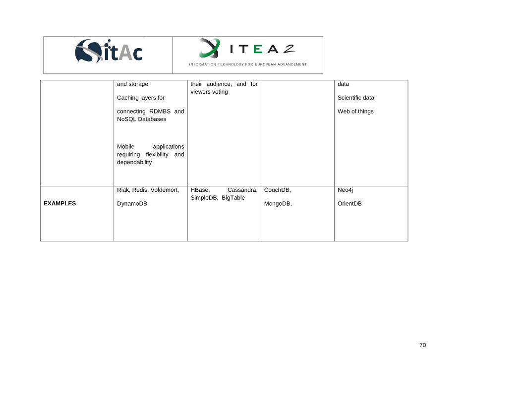
70
and storage
Caching layers for
connecting RDMBS and
NoSQL Databases
Mobile applications
requiring flexibility and
dependability
their audience, and for
viewers voting
data
Scientific data
Web of things
EXAMPLES
Riak, Redis, Voldemort,
DynamoDB
HBase, Cassandra,
SimpleDB, BigTable
CouchDB,
MongoDB,
Neo4j
OrientDB

38.1.1. Comparison of some NoSQL technologies
There are many implementations of each type of NoSQL databases. For this part, we have chosen to
introduce one of the most popular of each type, and then, to compare them.
38.1.1.1. Cassandra
Apache Cassandra is an open source distributed database management system. It is an Apache
Software Foundation top-level project designed to handle very large amounts of data spread out across
many commodity servers while providing a highly available service with no single point of failure. It is
under Apache License 2.0 [8]. Apache Cassandra is the technology of choice for such data-driven
organizations as Netflix, eBay, Constant Contact, Adobe, Comcast, Barracuda Networks and scores of
others [9].
38.1.1.2. CouchBase
CouchBase Server, originally known as Membase, is an open source, distributed NoSQL document-
oriented database that is optimized for interactive applications. CouchBase is licensed under the Apache
2.0 License [10].
38.1.1.3. CouchDB
Like MongoDB, CouchDB is open source. It is maintained by the Apache Software Foundation and is
made available under the Apache License v2.0. Unlike MongoDB, CouchDB was designed to mimic the
web in all respects [11].
38.1.1.4. HBase
HBase is a columnar database project in the Apache Software Foundation distributed under the Apache
Software License v2.0. HBase uses the Hadoop file system and MapReduce engine for its core data
storage needs.
38.1.1.5. MongoDB
MongoDB (from "humongous") is an open-source document database, and the leading NoSQL database
[12]. It is maintained by a company called 10gen as open source and is freely available under the GNU
AGPL v3.0 license. Commercial licenses with full support are available from 10gen.
38.1.1.6. Neo4j
One of the most widely used graph databases is Neo4J. A supported, commercial version is provided by
Neo Technology under the GNU AGPL v3.0 and commercial licensing [13]. Due to its graph data model,
Neo4j is highly agile and blazing fast. For connected data operations, Neo4j runs a thousand times faster
than relational databases [14].
38.1.1.7. Redis
Redis is an open-source, networked, in-memory, key-value data store with optional durability. It is written
in ANSI C. The development of Redis is sponsored by VMware. It is available on BSD Licenses [15].
38.1.1.8. Tokyo Cabinet/Tokyo Tyrant

72
Tokyo Cabinet is a key value pair library of routines for managing a database. The database is a simple
data file containing records. It is free, and licensed under the GNU Lesser General Public License.
38.1.1.9. SimpleDB
Amazon SimpleDB is a highly available and flexible non-relational data store that offloads the work of
database administration. Developers simply store and query data items via web services requests and
Amazon SimpleDB does the rest [16]. Amazon SimpleDB is licensed by Amazon Web Services, Inc.
38.1.1.10. Scalaris
Scalaris is a scalable, transactional, distributed key-value store. It was the first NoSQL database, which
supported the ACID properties for multi-key transactions. It can be used for building scalable Web 2.0
services [17].
38.1.1.11. Riak
One widely used open source key-value pair database is called Riak. It is developed and supported by a
company called Basho Technologies and is made available under the Apache Software License v2.0.
Riak is a very fast and scalable implementation of a key-value database. It supports a high-volume
environment with fast-changing data because it is lightweight [18].
38.1.1.12. Terrastore
Terrastore is a distributed, scalable and consistent document store supporting single-cluster and multi-
cluster deployments. It provides advanced scalability support and elasticity feature without loosening the
consistency at data level [19]. Terrastore is a very young Apache Licensed document.
38.1.1.13. Voldemort
Voldemort is a distributed data store that is designed as a key-value store used by LinkedIn for high-
scalability storage. The source code is available under the Apache 2.0 license [20].
38.1.1.14. Hypertable
Hypertable is a high performance, open source, massively scalable database modelled after BigTable,
Google's proprietary, massively scalable database [21]. It is available under the GNU General Public
License 2.0.
Table 6 and Table 7 depict different characteristics of those NoSQL databases. They present these
technologies following some characteristics:
● Data model: specifies the type of NoSQL database
● Consistency concept: the politic adopted for data consistency
● Storage model: defines how the NoSQL database manage the data storage
● Horizontal scalability: evaluate how the database can add nodes to the system
● Query possibilities: the query language used to manage data
● Data access and API: different possibilities to access to the data

73
● Adapted tasks (optimized for): the most performing task with this kind of database
● Replication: how the data is stored on multiples devices
● Graphical monitoring/Admin console
● Implementation language
● Programming language

TABLE 6. COMPARISON OF HBASE, CASSANDRA, MONGODB, COUCHDB, SIMPLEDB, REDIS AND NEO4J
39. EVALUATIO
N CRITERIA
40. HBASE 41. CASSAND
RA
42. REDIS 43. MONGODB 44. NEO4J 45. COUCHDB 46. SIMPLEDB
47. DATA
MODEL
48. Columnar 49. Columnar
Key Value Document store Graph Document store Key Value
CONSISTENCY
CONCEPT
Immediate
consistency
Eventual
consistency
Immediate
consistency
(can be
individually
decided for
each write
operation)
Optimistic
locking
Eventual
consistency
mediate
consistency
(can be
individually
decided for
each write
operation)
ACID compliant
Eventual
consistency
ACID compliant
Eventual
consistency
Eventual
consistency
Immediate
consistency
(can be
specified for
read operation)
STORAGE
MODEL
HDFS
Data is
distributed
across the
cluster and
every node of
the cluster has
the same role
Dictionary of
key value pairs
stored in
memory
BSON
documents with
GridFS
Nodes
relationship and
properties
JSON
Document
In pair based
distributed
database
Hosted on
Amazon Cloud
HORIZONTAL
SCALA
BILITY
Scale linearly
and
automatically
with a new
node
Read and write
throughput both
increase
linearly as new
machines are
added, with no
downtime or
The scalability
will be as good
as running on a
single partition
MongoDB
scales
horizontally
using sharding
Neo4j is
designed to run
in one machine
but has
massive
scalability
Can scale with
Read requests,
Writes requests
and
Data
SimpleDB also
enables
scalability by
allowing you to
partition your
workload
across multiple

75
interruption to
applications.
domains
QUERY Using of Hive Cassandra
Query
Language
(insert, get,
delete)
Redis Query
language
CRUD requests Cypher Query
Language
JavaScript Amazon
SimpleDB
Query
Language
DATA ACCESS
AND API
JAVA API
RESTFULL
HTTP API
Thrift
Thrift API
CLI
Proprietary
protocol
Mongo Wire
Protocol
Java API
RESTFUL
HTTP API
RESTFUL
HTTP API
JSON API
SOAP and Web
services
OPTIMIZED FOR
Random,
real-time
read/write
data access
Writes
Sorted sets CRUD
(Create, read,
update and
delete)
operations
Complex and
linked data
Web High availability
and flexibility,
with little data
REPLICATION
Selectable
replication
factor
Replication
strategies are
configurable
In default
Master-slave
replication
Master-slave
replication
Master-slave
replication (only
available on the
Enterprise
Master-master
replication
Master-slave
replication
Writes are
automatically
replicated
across
availability
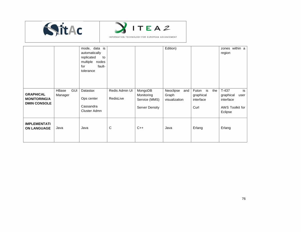
76
mode, data is
automatically
replicated to
multiple nodes
for fault-
tolerance
Edition) zones within a
region
GRAPHICAL
MONITORING/A
DMIN CONSOLE
HBase GUI
Manager
Datastax
Ops center
Cassandra
Cluster Admn
Redis Admin UI
RedisLive
MongoDB
Monitoring
Service (MMS)
Server Density
Neoclipse and
Graph
visualization
Futon is the
graphical
interface
Curl
T-437 is
graphical user
interface
AWS Toolkit for
Eclipse
IMPLEMENTATI
ON LANGUAGE
Java
Java
C
C++
Java
Erlang
Erlang

77
SUPPORTED
PROGRAMMING
LANGUAGES
C, C#, C++,
Groovy, Java,
PHP, Python
C, C++,
Clojure, Erlang,
Go, Haskell,
Java,
JavaScript,
Perl, PHP,
Python, Ruby,
Scala
C, C++, C#,
Clojure, Dart,
Erlang, Go,
Haskell, Java,
JavaScript,
Lisp, Lua
,Objective-C,
Perl, PHP,
Python, Ruby,
Scala,
SmallTalk, Tcl
ActionScript, C,
C++, C#,
Clojure,
ColdFusion, D,
Dart, Delphi,
Erlang, Go,
Groovy,
Haskell, Java,
JavaScript,
Lisp, Lua ,
Matlab, Perl,
PHP,
PowerShell,
Prolog, Python,
R, Ruby, Scala,
SmallTalk
. Net, Clojure,
Go, Groovy,
Java,
JavaScript,
Perl, PHP,
Python, Ruby,
Scala
C, C# ,
ColdFusion,
Erlang, Haskell,
Java,
JavaScript ,
Lisp, Objective-
C, OCaml,
Perl, PHP,
PL/SQL,
Python, Ruby,
Smalltalk
.Net, C, C++,
C#, Erlang,
Java, PHP,
Python, Ruby,
Scala

TABLE 7. COMPARISON OF SCALARIS, RIAK, TERRASTORE, VOLDEMORT, TOKYO CABINET/TOKYO TYRANT, COUCHBASE AND HYPERTABLE.
50. EVALUATION
51. CRITERIA
52. VOLDEM
ORT
53. RIAK 54. SCALARI
S
55. TOKYO
CABINET/T
OKYO
TYRANT
COUCH
BASE
(previous
membase)
TERRASTORE HYPERTABL
E
DATA MODEL key value
key value Key value Key value Document
store
Document store Columnar
CONSISTENCY
CONCEPT
Optimistic
locking. It
updates
replicas
asynchronous
ly, so it does
not guarantee
consistent
data.
Eventual
consistency
Transaction
processing
with strong
consistency
over replicas
While a writer is
connected to a
database,
neither readers
nor writers can
be connected.
While a reader
is connected to
a database,
other readers
can be
connected, but
writers cannot.
According to
this
mechanism,
data
consistency is
guaranteed with
Couchbase
Server
includes a
built-in
object-level
cache,
based on
memcached
, proven
data
caching
technology.
This provide
consistency
and high
performance
Terrastore provides
per-document
consistency
features: you're
guaranteed to
always get the
latest value of a
single document,
with read committed
isolation for
concurrent
modifications. More
complex
consistency/transac
tional requirements,
such as multi-
document
consistency, are not
supported in order
Consistency
is achieved
through a
distributed
consensus
protocol.

79
simultaneous
connections in
multitasking
environment.
to guarantee
scalability.
STORAGE
MODEL
It can store
data in RAM,
but it also
permits
plugging in a
storage
engine. It
supports a
Berkeley DB
and Random
Access File
storage
engine.
Riak objects
can be
fetched and
stored in
JSON format.
Objects can
be grouped
into buckets,
like the
Collections
supported by
document
stores. Does
not support
indices on
any fields
except the
primary key.
Scalaris uses
a structured
overlay with a
non-blocking
Paxos commit
protocol
The database is
a simple data
file containing
records, each is
a pair of a key
and a value.
Table database
does not
express simple
key/value
structure but
expresses a
structure like a
table of
relational
database. Each
record is
identified by the
primary key and
has a set of
multiple
columns named
with arbitrary
strings.
Couchbase
Server
persists all
data to disk
asynchrono
usly and lets
you store
datasets
larger than
the physical
RAM size.
Couchbase
automaticall
y moves
data
between
RAM and
disk and
keeps the
working set
in the
object-level
cache. The
storage
model is
Terrastore is a
distributed
document store
supporting single-
cluster and multi-
cluster
deployments. It is
elastic: you can add
and remove nodes
dynamically to/from
your running
cluster(s) with no
downtime and no
changes at all to
your configuration.
It uses
column
families that
can have any
number of
column
“qualifiers”. It
uses
timestamps
on data with
MVCC. It
requires an
underlying
distributed file
system such
as Hadoop,
and a
distributed
lock manager.

80
based in
JSON
documents
and
Memcache.
HORIZONTAL
SCALABILITY
Supports
automatic
sharding of
data.
Consistent
hashing is
used to
distribute data
around a ring
of nodes.
Data is
distributed
across nodes
using
consistent
hashing.
Consistent
hashing
ensures data
is evenly
distributed
around the
cluster and
new nodes
can be added
automatically,
with minimal
reshuffling.
Supports
sharding by
hashing on
the primary
key
In distributing
data over
nodes, it
allows key
ranges to be
assigned to
nodes, rather
than simply
hashing to
nodes. A
query on a
range of
values does
not need to
go to every
node, and it
also may
allow better
load
balancing,
depending on
key
distribution.
Scalability of
Tokyo Cabinet
is great. The
database size
can be up to
8EB (9.22e18
bytes).
Auto-
sharding
distributes
data
uniformly
across
servers,
enabling
direct
routing of
requests to
the
appropriate
server
without any
application
changes.
Adding (or
removing) a
server
initiates data
rebalancing
across the
cluster with
continuous
Documents are
partitioned and
distributed among
your nodes, with
automatic and
transparent re-
balancing when
nodes join and
leave. Query and
update operations
are distributed to
the nodes which
actually holds the
queried/updated
data, minimizing
network traffic and
spreading
computational load.
Hypertable
will break
tables into
ranges and
distribute
them to what
are known as
RangeServer
processes. T
hese
processes
manage
ranges of
table data
and run on all
slave server
machines in
the cluster.
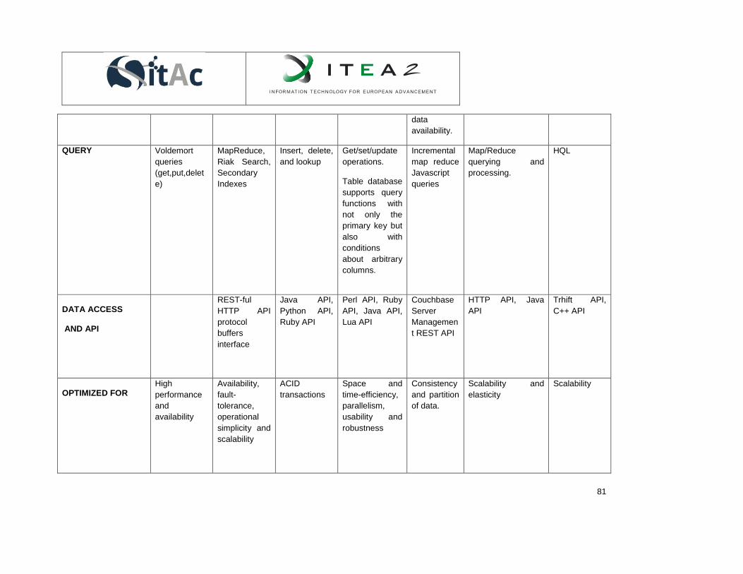
81
data
availability.
QUERY Voldemort
queries
(get,put,delet
e)
MapReduce,
Riak Search,
Secondary
Indexes
Insert, delete,
and lookup
Get/set/update
operations.
Table database
supports query
functions with
not only the
primary key but
also with
conditions
about arbitrary
columns.
Incremental
map reduce
Javascript
queries
Map/Reduce
querying and
processing.
HQL
DATA ACCESS
AND API
REST-ful
HTTP API
protocol
buffers
interface
Java API,
Python API,
Ruby API
Perl API, Ruby
API, Java API,
Lua API
Couchbase
Server
Managemen
t REST API
HTTP API, Java
API
Trhift API,
C++ API
OPTIMIZED FOR
High
performance
and
availability
Availability,
fault-
tolerance,
operational
simplicity and
scalability
ACID
transactions
Space and
time-efficiency,
parallelism,
usability and
robustness
Consistency
and partition
of data.
Scalability and
elasticity
Scalability
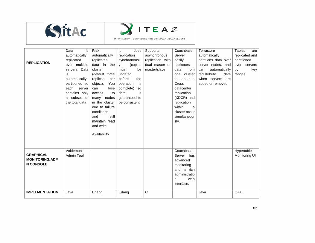
82
REPLICATION
Data is
automatically
replicated
over multiple
servers. Data
is
automatically
partitioned so
each server
contains only
a subset of
the total data
Riak
automatically
replicates
data in the
cluster
(default three
replicas per
object). You
can lose
access to
many nodes
in the cluster
due to failure
conditions
and still
maintain read
and write
Availability
It does
replication
synchronousl
y (copies
must be
updated
before the
operation is
complete) so
data is
guaranteed to
be consistent
Supports
asynchronous
replication with
dual master or
master/slave
Couchbase
Server
easily
replicates
data from
one cluster
to another.
Cross
datacenter
replication
(XDCR) and
replication
within a
cluster occur
simultaneou
sly.
Terrastore
automatically
partitions data over
server nodes, and
can automatically
redistribute data
when servers are
added or removed.
Tables are
replicated and
partitioned
over servers
by key
ranges.
GRAPHICAL
MONITORING/ADMI
N CONSOLE
Voldemort
Admin Tool
Couchbase
Server has
advanced
monitoring
and a rich
administratio
n web
interface.
Hypertable
Monitoring UI
IMPLEMENTATION Java Erlang Erlang C Java C++.

83
LANGUAGE
SUPPORTED
PROGRAMMING
LANGUAGES
Java, Python,
Perl, Erlang,
Ruby, PHP,
.NET, etc.
Java, Python,
Ruby
Perl, Ruby,
Java, Lua
Java, C#,
PHP, C,
Python and
Ruby.
Java C++. Java,
PHP, Python,
Perl, Ruby.

The first point we can retain is the fact that considered NoSQL databases provides huge possibilities of
Data access with APIs. The most of them provide high scalability and replication possibilities. As well,
they support, for the most of them, different programming languages. Java is the most common
supported language.
55.1. Data Aggregation
55.1.1. Hadoop Framework
Hadoop is an Apache-managed software framework derived from MapReduce [22]. Hadoop allows
applications based on MapReduce to run a large cluster of commodity hardware. It is designed to
parallelize data processing across computing nodes to computation and hide latency. It is based on a
distributed file system called HDFS (Hadoop Distributed File System) [23]. HDFS is a clustered approach
based on two components:
NameNode: the NameNode manage the arborescence of the file system. The location of the data
blocks is centralized on the NameNode. It also assigns tasks for each DataNode. In order to do it,
the namenode uses a daemon, the JobTracker. There is one NameNode in a cluster
DataNode: the DataNode store and returns data to the namenode when it is asked. It also uses a
TaskTracker to execute his tasks and to give information back to the NameNode
Hadoop is based on MapReduce algorithm. MapReduce is a processing model designed by Google as a
way of efficiently executing a set of functions against a large amount of data with a parallel and distributed
algorithm on a cluster. MapReduce comprises two processing programs: Map and Reduce.
The Map step consists to split up and to process data in a form of Key Value Pairs (KVP). The Reduce
step is a merging of KVP in a final result.
NoSQL databases use Hadoop to complete their tasks. Indeed, for example, queries and searching
operations are converted to MapReduce tasks.
Hadoop is a very powerful technology to deal with big data. However, to tackle big data challenges it is
also important to have some tools.
The most useful tools of Hadoop ecosystem are: Hive, Apache Pig, Sqoop, and Zookeeper. There are
also packages that bring statistical analysis and big data algorithm capabilities to Hadoop. One known
package is Apache Mahout.
55.1.1.1. Hive
Hive is a batch-oriented, data warehousing layer built on the core elements of Hadoop. It gives a SQL lite
interface to users. Hive is used for data mining and deeper analytics that do not require real time
behaviors. Hive uses three mechanisms for data organization for tables, partitions and buckets.
55.1.1.2. Apache Pig
Apache Pig is a platform for analyzing large data sets that consists of a high-level language for
expressing data analysis programs, coupled with infrastructure for evaluating these programs [24]. It is
designed to make Hadoop more approachable and usable by non-developers. Pig is very interactive and
support a language used to express data flows: Ping Latin. This language is very rich and allows doing
some operations like:

85
Loading and storing of data
Streaming data
Filtering data
Grouping and joining data
Sorting data
Combining and splitting data
55.1.1.3. Sqoop
Sqoop (SQL-to-Hadoop) is a tool designed for efficiently transferring bulk data between Hadoop and
structured data stores such as relational databases. So, it offers the capability to extract data from non-
Hadoop data stores, transform the data into a form usable by Hadoop and then, load the data into HDFS.
It is the ETL process (Extract, Transform, and Load). Its allows to do some tasks like
Import and map SQL directly into Hive
Generate Java classes
55.1.1.4. Zookeeper
Zookeeper is a centralized service for maintaining configuration information, naming, providing distributed
synchronization, and providing group services [25]. Zookeeper is very powerful and has the capability to
do:
Process synchronization
Configuration management
Self-election reliable messaging
55.1.1.5. Apache Mahout
The Apache Mahout machine learning library's goal is to build scalable machine learning libraries. The
Apache Mahout team defines its goal as following (from Mahout Project wiki):
Our core algorithms for clustering, classification and batch based collaborative filtering are implemented
on top of Apache Hadoop using the map/reduce paradigm. However we do not restrict contributions to
Hadoop based implementations: Contributions that run on a single node or on a non-Hadoop cluster are
welcome as well. The core libraries are highly optimized to allow for good performance also for non-
distributed algorithms
Mahout can be used for clustering of objects into categories, and identify M2M devices in a cellular
network, for example.
55.2. Data Analysis

86
55.2.1. Machine Learning: Techniques and Algorithm for Data Analysis
Machine learning can be defined as the set of techniques and methods that can be used to automatically
learn programs from data. It can be seen as an intersection of Computer Science and Statistics. While
Computer Science focuses on how to write programs and Statistics on how to infer conclusions from
data, Machine Learning focuses on how to get computers to program themselves in order to analyze
those data efficiently and effectively. Machine learning is actively used in a wide amount of disciplines like
Web search, spam filters, recommender systems, ad placement, credit scoring, fraud detection, stock
trading, drug design and many other applications [26]. It has been pointed out that machine learning will
be one of the key technologies of the next big wave of innovation [27].
According to the desired outcome of the algorithm, we can divide machine-learning algorithms into the
following types:
Supervised learning
Unsupervised learning
Semi-Supervised learning
55.2.1.1. Supervised Learning
The main goal of supervised learning algorithms is to learn a classification system that has been created
in advance.
Supervised learning is the most common technique used to train neural networks and decision trees. In
both cases, we want to be able to classify input data into one of the pre-determined classifications. These
techniques make use of supervision in the sense of these pre-existing categories that will be used for
classification. For neural networks, the supervision allow to minimize the error of the classification
produced by the network and for decision trees, the supervision is intended to choose the attributes that
provide the most power to discriminate categories.
Every supervised learning technique starts with the collection of the dataset. Although it is not
compulsory, it is recommended to take into account expert recommendations about which fields or
features to collect. If this is not feasible, as much information as possible should be collected hoping for
further discrimination of the proper features. Nevertheless, in most cases this proves to be inadequate to
perform induction, as it tends to contain noise and missing feature values, which force to perform
intensive pre-processing [28].
As we have just seen, depending on the data collection method, it may be necessary to perform
additional procedures in the dataset, for instance, to handle missing data or to perform noise detection.
Instance selection is also used when dealing with very large datasets for keeping the mining quality while
reducing the sample size.
It is critical also to be able to identify the subset of feature that is really relevant for the classification. The
existence of dependencies among features influenced negatively the accuracy of the supervised
classifiers. The discovery of meaningful features greatly contributes to a better understanding of the
classifier. Supervised models try to minimize the classification error on given inputs. This is how they are

87
built. These given inputs are the training set. There is an inherent risk associated to the use of this
training method, which is memorizing the training set rather than generalizing to learn a classification
technique. This risk is called over-fitting and can appear too if the training set has classification errors.
The design challenge for supervised learning is to construct algorithms powerful enough to learn complex
functions while robust enough to be able to generalize results.
As we have seen, supervised learning is closely related to classification. Next, we are going to present
the most typical types of supervised learning algorithms used for classification:
Decision Trees
Rule-based Classifiers
Linear Classifiers
Artificial Neural Networks
Bayesian Networks
Instance-based Classifiers
55.2.1.1.1. Decision Trees
Decision trees are a special case of trees that classify data points based on feature values. In these
trees, there is direct correspondence between each node in the tree and a feature in an instance to be
classified, and between each branch and a certain value of that feature. Classification for an instance is
performed starting at the root node and depending on their feature values.
Although there is plenty of methods for finding the feature that best divides the training data, according to
the studies found in the state of the art, it seems that there is no single best method [29]. Decision trees
are usually univariate although there are a few methods that construct multivariate trees like [30,31].
The most common and well-known algorithm for building decision trees is the C4.5 algorithm. C4.5 shows
a good compromise between error rate and speed. Its main drawback is that the training data must fit in
memory, although some authors [32,33] have proposed modifications to overcome these limitations.
55.2.1.1.2. Rule-based Classifiers
Rule-based classifiers can be defined from decision trees just by creating a separate rule for each path
from the root to the leaf in the tree. Nevertheless, it is also usual to derive them directly from training data.
The goal is to construct the smallest rule-set consistent with that training set.
A rule induction system has to generate decision rules both with high predictability or reliability. These two
properties are typically measured by the rule quality.
There are many rule-based algorithms. The two main paradigms for rule generation are creating rules
from decision trees and the separate-and-conquer rule-learning technique. Genetic algorithms have also
been used for rule learning. In these cases, the fitness function scores the classification accuracy of the
rule over a set of training instances. There is an iterative process that takes the population at each
iteration and generates a new population such that the overall fitness is increased.
Rule-based classifiers are better suited than decision trees for learning binary problems because they are
more comprehensible. On the contrary, if we deal with multiple class definitions, the learner has to be run
independently for each class. This is prone to rule inconsistency, something that simply does not happen

88
with decision trees. For this kind of problems, the divide and conquer approach used by decision trees is
more suitable than the separate and conquer approach used by rule-based algorithms. Separate and
conquer algorithms focus on one class at a time and create rules for identifying that class. This is, as we
have seen, independent from the rules created for the other classes. Because of this, for small datasets it
may be better to opt for the divide and conquer approach, which focus on the entire dataset, not in
specific classes.
Finally, notice that, as it happened with decision trees, the most remarkable feature of rule-based
algorithms is its comprehensibility.
55.2.1.1.3. Linear Classifiers
A linear classifier uses a linear combination of the features to be able to perform the classification. The
input feature to the classifier is a vector where each of its components corresponds with a particular
feature. To compute the output, a dot product with a weight vector is performed and a certain function f is
applied to the result. The weight vector is learned from a set of labelled training examples. Because of its
simplicity, linear classifiers are used when speed of classification is an issue.
Support Vector Machines (SVM) [34] perform classification by constructing a N-dimensional hyperplane
that divides the data into two categories. SVM are closely related to classical neural networks. In the SVM
context, predictor variables are known as attributes. For the hyperplane definition, attributes are
transformed into features. By feature selection, we mean the process of choosing the most appropriate
representation for the features. A set of features, which is nothing but a row of predictor values, is known
as vector. According to this definition, we could reformulate the goal of SVM as to find the optimal
hyperplane that separates cluster of vectors so that cases with different categories of the target variable
are at different sides of the hyperplane. The set of vector that are closest to the hyperplane are the
support vectors.
Depending on the complexity of the data set, it may be necessary to employ more than two predictor
variables or using non-linear curves for the separation of categories. Also there are situations where the
categories cannot be completely separated or where more than two categories have to be used.
55.2.1.1.4. Artificial Neural Networks
Artificial Neural networks (ANN) can be viewed as weighted directed graphs in which artificial neurons are
nodes and directed edges (with weights) are connections between neuron outputs and neuron inputs [35].
The most popular architecture for ANN is multilayer perceptrons. In this architecture, the units perform a
biased weighted sum of their inputs. This sum itself will be the input to its transfer function to compute the
neuron output. Under this scheme, the units are arranged in a layered feed forward topology. The
network complexity will depend on the number of layers and the number of inputs in each layer. While the
number of inputs and output units is usually defined by the problem, the number of hidden units to use is
not that straightforward and to be defined carefully.
Once we have defined the structure of the network, weights and thresholds have to be defined to
minimize the error made by the network. To evaluate this error, we use a training algorithm. The error of a
particular configuration of the network is evaluated by processing all the available cases in the training
data set and comparing the obtained output with the expected output. The network error is defined as a
combination of the target outputs. While in traditional linear model, it is possible to determine the

89
configuration that minimizes the error, because of the non-linearity of ANN we cannot be sure whether the
error is at its minimum or it can still be lowered.
To model the network error, the concept of error surface is introduced. For any possible configurations of
the N weights assigned, the error can be plotted as a function of the weights in the N+1 dimension as an
error surface. Our goal would be to find the minimum, if any, in that surface. Because of the complexity of
neural networks, it is not possible to analytically determine the global minimum. Alternative techniques
must have to be taken into account, typically gradient-based techniques, which try to find and then
improve local minima.
One desirable property would be the ability to generalize to new cases. There are no guarantees about
the error we will obtain when dealing with new data. Associated to this situation, it is the problem of over-
fitting. The more weights an ANN has, the more prone to over-fitting that it is. To deal with this, the
concept of selection set is introduced. The selection set is a portion of the training dataset that is reserved
and actually not used for training. As training progresses, training error naturally decreases and selection
error (that is, the error obtained when evaluating versus the selection set) decreases too. If the training
error stops dropping, it is god indicator that over-fitting is starting to occur, and training should stop
because the network is powerful enough to model the underlying function. Finally, a third set is reserved,
the test set, to ensure that the results of the selection and training are real and not something artificially
created from the training process. Notice that for this approach to be effective the test set must only be
used once, otherwise it becomes training data.
ANN has been applied to plenty of real-world problems. Their main drawback is their lack of ability to
reason about their output in a way that allows effective communication. Many researchers have tried to
improve the comprehensibility of ANN, for instance, by extracting symbolic rules from trained neural
networks [36].
55.2.1.1.5. Bayesian Networks
Bayesian Networks (BN) can be defined as a graphical model of the probability relationships existing
among a set of variables. It can be seen as a directed acyclic graph (DAG) where there is a one to one
relationship among nodes and features. Each node is random variable in the Bayesian sense. When
there exists an influence between features, there will be an arc joining them, while the absence of arcs
means conditional independence.
Bayesian networks can be used for learning. In order to accomplish that, two conditions must be fulfilled.
First, the structure of the DAG network has to be determined. Second, the parameters of the network
have to be found. There is a table for each of the variables (nodes) where it is reflected the local
conditional distribution of the variable with respect to its parents. From these relationships, the joint
distribution can be constructed just by multiplying the tables.
The dominant approach for learning Bayesian networks from data is based on the use of a scoring metric,
that evaluates the fitness of any given candidate network to the data, and a search procedure, that
explores the space of possible solutions. Most existing learning tools apply standard heuristic search
techniques. It has been shown that the selection of a single good hypothesis using scoring and greedy
search often leads to accurate predictions [37,38]
90
There are proposals [39] that focus on reducing the search space thus improving efficiency. Ant Colony
Optimization has also been proposed for finding the optimal structure of Bayesian networks [40].
Naïve Bayesian networks (NB) are a specific case of Bayesian networks where the DAG only has one
parent and several children and with a strong assumption of independence among child nodes in the
context of their parent. This assumption is wrong in most cases and this is why NB is less accurate than
other methods. The main advantage of NB classifiers is the short computational time for training.
To summarize, we would like to stress that BN are specially interesting, compared to decision trees or
neural networks, when there is prior information that can be taken into account about a certain problem,
e.g. some expertise or domain knowledge. On the other hand, BN are not suitable for datasets with many
features because of the complexity of the network construction.
55.2.1.1.6. Instance-based Classifiers
Instance-based learning algorithms store the training samples and instead of first generalizing and later
classifying, they just store the training samples and try to compute the generalization only when
classification is needed. They are examples of lazy-learning algorithms. This kind of algorithms requires
less computation time during the training phase but, on the contrary, more computational time during the
classification process.
k-Nearest Neighbor (kNN) is based on the fact that instances in a dataset will tend to be closer to other
instances that have similar features. Taking this into account, a particular instance could be classified by
observing the class of its nearest neighbors. kNN uses the k-nearest neighbors and identify the most
frequent class label. Weighting schemes can be used to model the influence of each instance. Also,
attributes can be weighted.
kNN has large storage requirements and is very sensitive to the similarity function used to compare
instances and to the choice of k. It has been shown that the performance of kNN is not sensitive to the
choice of k when k is large, which will be the case in high dimensionality cases.
55.2.1.2. Unsupervised Learning
While supervised learning starts from labeled data and tries to generalize from the already classified
examples, unsupervised learning tries to find any structure underlying unlabeled data. Among the
approaches used for unsupervised learning, we can find clustering techniques (like k-Means or mixture
models) and blind signal separation using feature extraction techniques for dimensionality reduction.
K-means [42] tries to classify data point into a set a certain number of clusters. The goal is to minimize
the distance from the data points to the center of the cluster where it has been classified. K-means is an
iterative procedure. First, taking into account the a priori clusters, we have to set the k initial centroids,
one for each cluster. Second, we associate every data point to its nearest centroid. Finally, we
recomputed the centroids. Taking into account these new centroids, we start over. We iterate over this
process until there is no change in centroids’ positions.
The k-means method is widely used because of its simplicity but has some drawbacks, though. There is
no guarantee that an optimal solution will be found and it is quite sensitive to the initial location of the
centroids. Also it is not robust to outlying data. Another shortcoming of k-means based methods is that
they only can process isotropic clusters such as circles, spheres, etc.
91
Fuzzy clustering algorithms or Soft K-Means (as opposed hard K-means), e.g. C-means [43], allow a data
point to belong to more than one cluster and associated to every data point there is a set of membership
levels, which measure the strength of the association of the data point to each particular cluster.
Unsupervised learning can also be applied to topology learning. This family of algorithms tries to infer the
representation of the topology structure of a high-dimension data distribution. Most of the proposals
require a predetermination of the network size [44], the network structure or both [45].
55.2.1.3. Semi-supervised learning
Semi-supervised learning is the kind of learning algorithms where we a have a small subset of labeled
data and a big amount of unlabeled data. Under suitable assumptions, it uses unlabeled data to help
supervised learning task. The cost associated to labeling the data may deem impossible to label the
whole data set, while acquisition of labeled data may be easy and cheap. In such situations, semi-
supervised learning can be of great value. A good review of semi-supervised learning techniques can be
found in [46].
55.2.2. Distributed and Parallel Architectures for Machine Learning
In the context of the SITAC project, the amount of data that is expected to be collected stored and
processed is huge. The first part of this document is devoted to how to efficiently store and process those
heterogeneous data sets. One of the strongest points in the project is to be able to classify, infer and
extract valuable information from data. While traditional machine learning approaches have proven
valuable for those tasks, if we have to deal with data sets too large not to be handled on a single machine
or that require statistical inference to be fast or in near real-time, those approaches just fail. The best
algorithm for a given problem may change dramatically as more data becomes available [47]. This new
situation has led to an increasing interest in distributed algorithms for machine learning, taking advantage
of the increasing availability of multi-core architectures and the commoditization of grid computing.
There are scenarios where it can be found appropriate to move from single-machine processing to
parallel and distributed architectures. According to [48], these scenarios are characterized by:
Large number of data instances: the number of potential training examples is big enough to make
not feasible to process that in one single machine.
High input dimensionality: in some cases, data instances are represented by a high number of
features. Machine learning algorithms may partition computation across the set of features, which
allow for dealing with very complex scenarios.
Model and algorithm complexity: there are machine learning algorithms that are based either on
complex or on computationally expensive routines to provide high-accuracy results. Distributing
the computation across multiple processing units could help to deal with learning on very large
datasets.
Inference time constraints: tight constraints on inference time may only be met if we opt for
parallelized versions of algorithms.

92
Prediction cascades: Sequential, interdependent predictions may be associated with highly
complex joint output states that could take advantage of parallelization.
Model selection and parameter sweeps: Tuning parameters of algorithms that require multiple
executions of learning and inference are naturally suited for concurrent execution.
If we have a deeper look into the problem of scaling up machine learning algorithms, it can be seen that
the problem must be tackled from different approaches. First, there is a need for programming
frameworks adapted for parallelizing learning algorithms. MapReduce can be employed for parallelizing
the training of decision trees ensembles, a class of algorithms that includes methods such as boosting
and bagging. PLANET [49] is able to distribute the tree construction across multiple processing units
expanding multiples nodes in each tree, leveraging the data partitioning which is implicit in the tree and
using both parallel and local execution when convenient. A two-orders-of-magnitude on a 200-node
MapReduce cluster on datasets large enough not be processed on a single node can be achieved using
PLANET. DryadLINQ [50] is a declarative data-parallel programming language that compiles programs
down to reliable distributed computations, which are executed by the Dryad execution engine. The Dryad
execution engine is able to scale up computations across large clusters of machines. It main advantages
are the ease of programming and its strong performance across multi-gigabyte datasets. IBM Parallel
Machine Learning Toolbox (PML) eases down the implementation of parallel versions of machine learning
algorithms. PML represents algorithms as a sequence of operators subject to algebraic rules of
commutability and associability. Such operators correspond with algorithm steps during which training
instances can be exchanged and partitioned in different ways, which helps it parallelization. Other
interesting project is Apache mahout. Apache Mahout provides a library of machine learning algorithms
developed for Hadoop.
On the other hand, we can also deal directly with the construction of parallelized versions of machine
learning algorithms. Several authors have shown how to parallelize the training of Support Vector
Machines (SVM) [51,52]. LambdaMART is a boosted decision tree algorithm for learning to rank. There
are different distributed versions of LambdaMART [53] that improve the algorithm performance up to one
order of magnitude by partitioning the features across nodes (citation needed). Statistical latent variable
model, such as topic models, can also be distributed. This allows to scale up to large datasets by
distributing data instances and exchange statistics across nodes. The underlying idea is to distribute the
distributed collapse Gibbs sampling, a Markov Chain Monte Carlo technique, for algorithms such as
Latent Dirichlet Allocation and Hierarchical Dirichlet Processes as well as Bayesian networks in general.
Clustering methods can be parallelized using different techniques. Parallel spectral clustering techniques
[54] are one of them. They are composed of three stages: sparsification of the affinity matrix, subsequent
eigende composition and obtaining final clusters via k-means using projected instances. Sparsification
can be distributed using MapReduce and the other two steps using MPI.
Apart from traditional supervised and unsupervised learning schemes, there are other interesting
proposals. In online learning algorithms, training instances arrive in a stream and learning is performed on
one example at a time. Features are partitioned (“sharded”) across cores and nodes achieving a speedup
factor of 6 on a cluster of nine machines [55]. For graph-based semi-supervised classification, heuristics
have been proposed to reorder graph nodes for the optimization of message passing, both for multicore
and distributed settings, which are able to scale up to a 85% efficiency on a 1000 core distributed
computer for a dataset of 120 million graph instances, in the context of speech recognition. Several other
93
proposals for transfer learning and distributed learning selection can also be found. P2P networks have
also been studied for distributed data mining [56].
Conclusion
Big data management induces issues like data collection, storage, aggregation and analysis. For the data
storage, data have to be stored with in an efficient, scalable and powerful database. The database also
has to deal with real time stream information. In view of those needs, a first approach should be to test
some NoSQL databases in order to choose the most adaptable for the project. Thus, it will be interesting
to test:
CouchDB due to his web oriented approach
Neo4j because it offers a great possibilities of query and is based on Graph model. This model is
very adapted to manage linked data
Hbase: it allows an efficient random access in real time for read and writes. In addition, its HDFS
data storage model enables an easy integration with Hadoop
MongoDB: it is the most common NoSQL databases.
DynamoDB, as a good representative of key-value pair NoSQL databases.
Finally, regarding data analysis, it is necessary to take into account the requirements imposed by the type
and volume of data, which will be collected in this project. While traditional machine learning approaches
have proven valuable for those tasks, if we have to deal with data sets too large not to be handled on a
single machine or that require statistical inference to be fast or in near real-time, those approaches just
fail. There is a need for either parallelized implementations of existing machine learning algorithms or for
developing parallel versions of existing machine learning techniques. Both approaches will be considered
during this project.
References
[1] Ji, Shouling, et al. "Cell-based snapshot and continuous data collection in wireless sensor
networks." ACM Transactions on Sensor Networks (TOSN) 9.4 (2013): 47.
[2] Durmaz Incel, Ozlem, et al. "Fast data collection in tree-based wireless sensor networks." Mobile
Computing, IEEE Transactions on 11.1 (2012): 86-99.
[3] D. S. De Couto, D. Aguayo, J. Bicket, and R. Morris, “A high-throughputpath metric for multi-hop
wireless routing,” Wireless Netw., vol. 11,no. 4, pp. 419–434, 2005.
[4] Bellavista, Paolo, et al. "Convergence of MANET and WSN in IoT Urban Scenarios." Sensors
Journal, IEEE 13.10 (2013): 3558-3567.
[5] R.K. Ganti, Y. Fan Ye, L. Hui, “Mobile crowdsensing: current state and future challenges,” IEEE
Comm. Mag., Vol. 49, No. 11, pp. 32-39, 2011.
[6] "ibm," What is big data, [Online]. Available: http://www-01.ibm.com/software/data/bigdata/.
[Accessed 26 June 2013].
[7] "Wikipedia," NoSQL, 23 June 2013. [Online]. Available: https://en.wikipedia.org/wiki/NoSQL.
[Accessed 25 June 2013].
94
[8] "Wikipedia," 19 june 2013. [Online]. Available: http://en.wikipedia.org/wiki/Apache_Cassandra.
[Accessed 25 june 2013].
[9] "Datastax," Apache Cassandra, 2013. [Online]. Available: http://www.datastax.com/what-we-
offer/products-services/datastax-enterprise/apache-cassandra. [Accessed 25 June 2013].
[10] "Wikipedia," Couchbase Server, 23 june 2013. [Online]. Available:
http://en.wikipedia.org/wiki/Couchbase_Server. [Accessed 25 june 2013].
[11] K. Marcia, H. Judith , N. Alan, H. Fern and K. Dan, "www.dummies.com," Document Databases in
a Big Data Environment, April 2013. [Online]. Available: http://www.dummies.com/how-
to/content/document-databases-in-a-big-data-environment.html. [Accessed 24 June 2013].
[12] "MongoDB official web site," Agile and Scalable, 2013. [Online]. Available:
http://www.mongodb.org/. [Accessed 25 June 2013].
[13] H. Judith, N. Alan, H. Fern and K. Marcia , "www.dummies.com," Graph databases in a big data
environment, April 2013. [Online]. Available: http://www.dummies.com/how-to/content/graph-databases-
in-a-big-data-environment.html. [Accessed 25 June 2013].
[14] "Neo4j official web site," The World's Leading Graph Database, 2013. [Online]. Available:
http://www.neo4j.org/. [Accessed 24 June 2013].
[15] "Wkipedia," Redis, 25 June 2013. [Online]. Available: http://en.wikipedia.org/wiki/Redis.
[Accessed June 25 2013].
[16] "SimpleDB official web site," Amazon SimpleDB (beta), 2013. [Online]. Available:
http://aws.amazon.com/simpledb/. [Accessed 25 June 2013].
[17] "Google Code," Scalaris, a distributed transactional key-value store, [Online]. Available:
http://code.google.com/p/scalaris/. [Accessed 2013 June 2013].
[18] M. Kaufman, H. Judith , N. Alan and H. Fern, Big Data for Dummies, Wiley, 2013.
[19] "Live dbpedia," About: Terrastore, [Online]. Available: http://live.dbpedia.org/page/Terrastore.
[Accessed 25 June 2013].
[20] "Project voldemort web site," Project Voldemort a distributed database, [Online]. Available:
http://www.project-voldemort.com/voldemort/. [Accessed 25 June 2013].
[21] "Hypertable Web site," Overview, [Online]. Available: http://hypertable.com/documentation/.
[Accessed 25 June 2013].
[22] J. Dean and S. Ghemawat, "MapReduce: simplified data processing on large clusters," in
Proceedings of the 6th conference on Symposium on Opearting Systems Design \& Implementation -
Volume 6, Berkeley, CA, USA, 2004.

95
[23] K. Shvachko, H. Kuang, S. Radia and R. Chansler, "The Hadoop Distributed File System," in
Proceedings of the 2010 IEEE 26th Symposium on Mass Storage Systems and Technologies (MSST),
Washington, DC, USA, 2010.
[24] "Apache pig," Welcome to Apache Pig, 2012. [Online]. Available: http://pig.apache.org/.
[Accessed 25 June 2013].
[25] "Apache Zookeper," What is Zookeeper?, 2010. [Online]. Available: http://zookeeper.apache.org.
[Accessed 25 June 2013].
[26] P. Domingos, "A few useful things to know about machine learning," Commun.ACM, vol. 55, no.
10, pp. 78-87, oct 2012.
[27] J. Manyika, M. Chui, B. Brown, J. Bughin, R. Dobbs, C. Roxburgh and A. H. Byers, "Big data: The
next frontier for innovation, competition, and productivity," 2011.
[28] S. Zhang, C. Zhang and Q. Yang, "Data preparation for data mining," Applied Artificial
Intelligence, vol. 17, pp. 375-381, 2003.
[29] S. K. Murthy, "Automatic Construction of Decision Trees from Data: A Multi-Disciplinary Survey,"
Data Min.Knowl.Discov., vol. 2, no. 4, pp. 345-389, dec 1998.
[30] J. Gama and P. Brazdil, "Linear tree," Intelligent Data Analysis, vol. 3, no. 1, p. 1, 1999.
[31] Z. Zheng, "Constructing X-of-N Attributes for Decision Tree Learning," Mach.Learn., vol. 40, no.
1, pp. 35-75, jul 2000.
[32] S. Baik and J. Bala, "A Decision Tree Algorithm for Distributed Data Mining: Towards Network
Intrusion Detection," vol. 3046, pp. 206-212, 2004.
[33] J. Gehrke, R. Ramakrishnan and V. Ganti, "RainForest\—A Framework for Fast Decision Tree
Construction of Large Datasets," Data Min.Knowl.Discov., vol. 4, no. 2-3, pp. 127-162, jul 2000.
[34] L. González, C. Angulo, F. Velasco and C. A., "Rapid and brief communication: Unified dual for
bi-class SVM approaches," Pattern Recogn., vol. 38, no. 10, pp. 1772-1774, oct 2005.
[35] A. K. Jain, J. Mao and K. M. Mohiuddin, "Artificial neural networks: a tutorial," Computer, vol. 29,
no. 3, pp. 31-44, 1996.
[36] Z.-H. Zhou, Y. Jiang and S.-F. Chen, "Extracting symbolic rules from trained neural network
ensembles," AI Commun., vol. 16, no. 1, pp. 3-15, jan 2003.
[37] D. M. Chickering, "Optimal structure identification with greedy search," J.Mach. Learn.Res., vol.
3, pp. 507-554, mar 2003.
[38] I. H. Witten and E. Frank, Data Mining: Practical Machine Learning Tools and Techniques, Third
Edition (Morgan Kaufmann Series in Data Management Systems), San Francisco, CA, USA: Morgan
Kaufmann Publishers Inc, 2011.

96
[39] S. Acid and L. M. de Campos, "Searching for Bayesian Network Structures in the Space of
Restricted Acyclic Partially Directed Graphs," J.Artif.Intell.Res.(JAIR), vol. 18, pp. 445-490, 2003.
[40] L. M. de Campos, J. M. Fernández-Luna, J. A. Gómez and J. M. Puerta, "Ant colony optimization
for learning Bayesian networks," International Journal of Approximate Reasoning, vol. 31, no. 3, p. 291,
2002.
[41] M. G. Madden, "The Performance of Bayesian Network Classifiers Constructed Using Different
Techniques," in In Working notes of the ECML/PKDD-03 workshop on, 2003.
[42] A. Likas, N. Vlassis and J. J. Verbeek, "The global k-means clustering algorithm," Pattern
Recognition, vol. 36, no. 2, p. 451, 2003.
[43] J. C. Bezdek, R. Ehrlich and W. Full, "FCM: The fuzzy c-means clustering algorithm," Computers
& Geosciences, vol. 10, no. 2–3, p. 191, 1984.
[44] T. M. Martinetz, S. G. Berkovich and K. J. Schulten, "`Neural-gas' network for vector quantization
and its application to time-series prediction," Neural Networks, IEEE Transactions on, vol. 4, no. 4, pp.
558-569, 1993.
[45] T. Kohonen, "Self-organized formation of topologically correct feature maps," Biological
cybernetics, vol. 43, no. 1, pp. 59-69, 1982.
[46] X. Zhu, "Semi-Supervised Learning Literature Survey," 2005.
[47] M. Banko and E. Brill, "Scaling to very very large corpora for natural language disambiguation," in
Proceedings of the 39th Annual Meeting on Association for Computational Linguistics, Stroudsburg, PA,
USA, 2001.
[48] M. B. (. ,. J. L. (. Ron Bekkerman (Editor), Scaling up Machine Learning: Parallel and Distributed
Approaches, Cambridge: Cambridge University Press, 2011.
[49] B. Panda, J. S. Herbach, S. Basu and R. J. Bayardo, "PLANET: massively parallel learning of
tree ensembles with MapReduce," Proc.VLDB Endow., vol. 2, no. 2, pp. 1426-1437, aug 2009.
[50] Y. Yu, M. Isard, D. Fetterly, M. Budiu, \. Erlingsson, P. K. Gunda and J. Currey, "DryadLINQ: a
system for general-purpose distributed data-parallel computing using a high-level language," in
Proceedings of the 8th USENIX conference on Operating systems design and implementation, Berkeley,
CA, USA, 2008.
[51] S. Fine and K. Scheinberg, "Efficient svm training using low-rank kernel representations,"
J.Mach.Learn.Res., vol. 2, pp. 243-264, mar 2002.
[52] J. C. Platt, "Advances in kernel methods," B. Sch\{o}lkopf, C. J. C. Burges, A. Smola and e. J.,
Eds., Cambridge, MA, USA, MIT Press, 1999, pp. 185-208.
[53] Y. Ganjisaffar, R. Caruana and C. V. Lopes, "Bagging gradient-boosted trees for high precision,
low variance ranking models," in Proceedings of the 34th international ACM SIGIR conference on
Research and development in Information Retrieval, New York, NY, USA, 2011.
97
[54] W.-Y. Chen, Y. Song, H. Bai, C.-J. Lin and E. Y. Chang, "Parallel Spectral Clustering in
Distributed Systems," IEEE Trans.Pattern Anal.Mach.Intell., vol. 33, no. 3, pp. 568-586, mar 2011.
[55] D. Hsu, N. Karampatziakis, J. Langford and A. J. Smola, "Parallel Online Learning," CoRR, vol.
abs/1103.4204, 2011.
[56] S. Datta, C. R. Giannella and H. Kargupta, "Approximate Distributed K-Means Clustering over a
Peer-to-Peer Network," IEEE Transactions on Knowledge and Data Engineering, vol. 21, no. 10, pp.
1372-1388, 2009.

98
56. Crowd-based Technologies
This chapter aims to identify what is Crowd-based Technologies for the future. This foresight will help
expose future research themes with high innovation and business potential, based on a timeframe
roughly 15 years ahead at least. The purpose of crowd-based technologies is to establish a strong
community across multi-technology fusion from partner organizations.
Trends
● Emergence of a new model of computation named crowdsourcing, which exploits human
computation - "wisdom of the crowd".
● Crowdsourcing or crowd-based services, the trend is toward "everyone as a service" [1].
● Emergence of distributed sensing, using mobile phones, where the sophisticated sensing,
processing, and communication capabilities of millions of smartphone users can be used towards
a common sensing goal [2]. Moreover, the distributed sensing data collection from mobile
phones and other devices will produce an essential part of the big data trend.
● The rise of social media platforms has shown that people want to create and share their content
with others [3]. In the future, this will be included in the future Internet of Things (IoT) as part of
social media.
● Public organizations will provide open data for the creation of new services. As part of the open
data, public authorities also allow the generation from crowd behavior in people's daily lives. This
also enables rethinking of data as learning human behavior, with history and future planning.
● Big data, including IoT, and open data trends will enable digital service fuse together with crowd-
based data. This kind of fusion also make the data appear in new forms, while gluing these
together can be used to create new service business models.
56.1. Crowd-based Services
Crowd-based services must be revisited and redefined when big data opportunities become clearer. The
interplay between things and people based on various sensor-embedded devices makes massive data
gathering possible. In the future, we will have to revise our conceptualization of how we look at the world,
due to these new sources of data and big data. So a service system can be broadly understood to
consist of people and ICT (Information and Communication Technology) systems for providing smart
service (it can be named as: ecology ICT system, where the Ecology is the scientific study of interactions
among organisms and their environment, that is, the interactions which organisms have with each other
and with their abiotic environment). What is the essence of smartness? It is the idea that the services
have some goals as systems that bring benefits to themselves, e.g., better user experience based on ICT
system and big data mining. In summary, not only recognize, link and manage the things (IoT), and even
mine the essence and laws inside the "things" (include people).
99
Which aspects will be included for crowd-based services? As described above, our "crowd-based" is
based on big data mining. Crowdsourcing, and further mobile crowdsourcing, open data, and Internet of
things all are steps that elaborate the link between the crowd and big data.
● Crowdsourcing. In its broadest sense, crowdsourcing could be viewed as synonymous with
collective intelligence. But in the information service domain, this conception is used more
frequently: everyone has ideas about how to improve the products or services which they use,
how to simplify processes, or how to reduce costs. Crowdsourcing is based on the "crowd"
process. The crowd can bring interesting, nontrivial, and non-overlapping information, insights, or
skills, which, when are used through appropriate aggregation and selection mechanisms, can add
the quality of solutions [4].
● Mobile crowdsourcing. A remarkable trend in crowdsourcing is the use of mobile devices: it
breaks the time and space barriers between people and enables them to share information and
knowledge [5]. Mobile crowdsourcing has the potential to help to tackle an array of new problems
that involve real-time data collection from a large number of participants.
● Open data. In recent years, open data initiatives have emerged, and are now available in several
countries [6]. Such initiatives consist of opening and sharing the public data of a country/city.
The data can be reused to develop added-value services and applications or improve the quality
of existing services and applications.
● Internet of Things (IoT). IoT is a computing concept that describes a future where everyday
physical objects will be connected to the Internet and will be able to identify themselves to other
devices. Based on the daily data from the IoT, the big-data-based research will spring up.
56.2. Crowd-based Applications
Currently research trend is shifted towards developing rich set of social networking, environmental and
infrastructure mobile applications. In particular, with the proliferation of smartphones and their apps
stores, mobile crowdsensing is used in a plethora of different applications of which we enumerate a few
here.
CenceMe [9], a social networking application developed by Darmouth College, classifies citizen activities
(walking, driving, exercising…) by sensing the level of noise or the mobile direction and then
subsequently share these activities via social networks.
For the environmental MCS (Mobile CrowdSensing), the mobile user is involved to measure some natural
phenomenon. In PEIR [10], authors measured the urban pollution level based on collected data samples
through the individual’s mobile microphones. Impact of Citizens on their respective environment is studied
(ex: carbon emission) based on the sensed activities and locations. Another example is the IBM project,
CreekWatch, where users report the water level and its quality in creeks by sending captured pictures or
even simple text messages.
Researchers are also working on several transportation and traffic monitoring applications. MIT VTrack
project [11] provides fine-grained traffic information on a large scale using mobile phones that facilitate
services such as accurate travel time estimation for improving commute planning. Similarly, Nericell

100
project [12] utilizes individuals mobile phones to not only determine average speed or traffic delays, but
also detect honking levels and potholes on roads .
Mobile crowdsensing is an emerging field of research requiring further attention from researchers and
developers in order to overcome several challenges concerning the heterogeneity of mobile hardware
and OS, the energy efficiency and the network bandwidth reuse.
In recent years, in the crowdsourcing domain, mobile crowdsourcing is an increasingly popular
mechanism to realize crowd-based applications which use a large volume of real-time data to improve
daily life. Twitter is a breakthrough for mobile-crowdsourcing-based applications. Yan et al. [2]
demonstrated "mCrowd", an iPhone-based mobile crowdsourcing platform, which enables mobile users to
fully utilize the rich sensors with which the iPhones are equipped to participate and accomplish
crowdsourcing tasks.
Väätäjä et al. [3] conducted two user studies to support the development of future mobile crowdsourcing
processes and mobile tools for news reporting. Moreover, the findings of literature [3] revealed that SMS
messages were experienced as an easy and handy means for news assignments.
A mobile application called "txteagle" [7] is a system that enables people to earn small amounts of money
by completing simple tasks (such as translation, transcription, and surveys) on their mobile phone.
Mobile crowdsourcing can also be used to design smart parking. Chen et al. [5] studied the properties of
crowdsourcing in the context of smart parking, and also investigated the use of information collected
through crowdsourcing for parking guidance, which is integrated into a road navigation system (as a
design alternative to lower the cost to install and maintain a dedicated infrastructure). The basic idea of
the parking guidance system is: each participant driver helps with data acquisition, and in return, either
the system provides the aggregate parking availability map and users make uncoordinated decisions, or
the system provides customized recommendations of parking locations and navigation to the participants
and thus attempts to coordinate their behavior.
Ubiquitous crowdsourcing is another popular mechanism to realize crowd-based applications [8]. With
the adoption of mobile, digital and social media the crowd is increasingly reporting and acting upon
events in smart environments; and sharing their data and experiences. The design goal of ubiquitous-
crowdsourcing-related applications: engage crowd members as sensors, controllers and actuators to
make the environments around us smart.
Conclusion
Using the "wisdom of the crowd" is main idea for crowd-based technologies. Moreover, in current days,
along with the construction of digital (or smart) cities, big data era is coming. The big-data-based "crowd"
will be different from the traditional one. Therein, the mobile and ubiquitous "crowd", are two promising
aspects. In the future, the concept of service needs to be revisited based on the "smart city" frame - what
is the essence of smartness? The "crowd" will be an attractive mechanism for processing data from the
massive data, and for improving the quality of service (make the environment around us smart).
References

101
[1] C. Petrie, "Plenty of Room Outside the Firm," IEEE Internet Computing, vol. 14, no. 1, pp. 92-96,
2010.
[2] T. Yan et al., "Demo Abstract: mCrowd: A Platform for Mobile Crowdsourcing," SenSys'09,
November 4-6, Berkeley, CA, USA, ACM, pp. 347-348, 2009.
[3] H. Väätäjä et al., "Crowdsourced News Reporting: Supporting News Content Creation with Mobile
Phones," MobileHCI’11, August 30-September 2, Stockholm, Sweden, ACM, pp. 435-444, 2011.
[4] J.G. Davis, "From Crowdsourcing to Crowdservicing," IEEE Internet Computing, vol. 15, no. 3, pp.
92-94, 2011.
[5] Chen, X., Santos-Neto, E. and Ripeanu, M. "Crowd-based Smart Parking: A Case Study for Mobile
Crowdsourcing," 5th International Conference on Mobile Wireless Middle Ware, Operating Systems
and Applications, Berlin, Germany, pp. 16-30, 2013.
[6] http://www.data.gov/ and http://data.gov.uk/
[7] Eagle, N., "txteagle: Mobile Crowdsourcing," DGD'09 Proceedings of the 3rd International
Conference on Internationalization, Design and Global Development. Springer-Verlag, pp. 447-456,
2009.
[8] M. Vukovic et al., "Ubiquitous Crowdsourcing," Proceedings of the 12th ACM International
Conference Adjunct Papers on Ubiquitous Computing Adjunct, Copenhagen, Denmark, pp. 523-
526, 2010.
[9] E. Miluzzo et al., “Sensing meets Mobile Social Networks: The Design, Implementation, and
Evaluation of the CenceMe Application,” Proc. 6th ACM SenSys, 2008, pp. 337–50.
[10] M. Mun et al., “Peir, the Personal Environmental Impact Report, as a Platform for Participatory
Sensing Systems Research,” Proc. 7th ACM MobiSys, 2009, pp. 55–68.
[11] A. Thiagarajan et al., “VTrack: Accurate, Energy-Aware Traffic Delay Estimation Using Mobile
Phones,” Proc. 7th ACM SenSys, Berkeley, CA, Nov. 2009.
[12] P. Mohan, V. Padmanabhan, and R. Ramjee, “Nericell: RICH monitoring of Road and Traffic
Conditions Using Mobile Smartphones,” Proc. ACM SenSys, 2008, pp. 323–36.
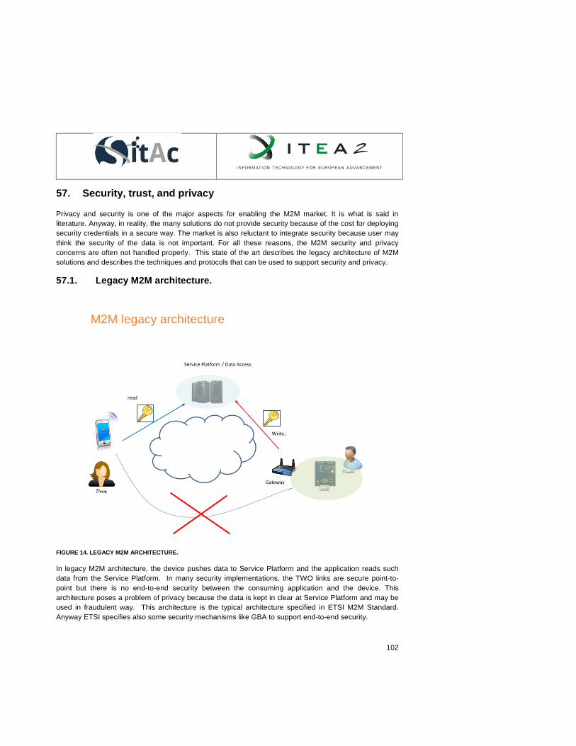
102
57. Security, trust, and privacy
Privacy and security is one of the major aspects for enabling the M2M market. It is what is said in
literature. Anyway, in reality, the many solutions do not provide security because of the cost for deploying
security credentials in a secure way. The market is also reluctant to integrate security because user may
think the security of the data is not important. For all these reasons, the M2M security and privacy
concerns are often not handled properly. This state of the art describes the legacy architecture of M2M
solutions and describes the techniques and protocols that can be used to support security and privacy.
57.1. Legacy M2M architecture.
Daisy
Donald
Service Platform / Data Access
Gateway
M2M legacy architecture
Write..
read
FIGURE 14. LEGACY M2M ARCHITECTURE.
In legacy M2M architecture, the device pushes data to Service Platform and the application reads such
data from the Service Platform. In many security implementations, the TWO links are secure point-to-
point but there is no end-to-end security between the consuming application and the device. This
architecture poses a problem of privacy because the data is kept in clear at Service Platform and may be
used in fraudulent way. This architecture is the typical architecture specified in ETSI M2M Standard.
Anyway ETSI specifies also some security mechanisms like GBA to support end-to-end security.

103
In OneM2M standard which is worldwide in progress M2M standard, a huge effort is provided to support
authorization mechanism and end-to-end security. Nevertheless, the underlying problems for end-to-end
security are the deployment of the security credentials and the notion of user and owner of devices and
objects and related data.
See first proposed SITAC Trust Model in SITAC Architecture document for an overview of the SITAC
vision of t M2M Trust Model.
Anyway, even in legacy architecture, they are security issues at alllevel of the communication links.
57.2. Security concepts.
The security concepts are the following:
Confidentiality: the data shall be available/disclosure to legitimate entities.
Authentication: the way to insure that a peer entity is legitimate
Integrity: the data shall not be modified during data transfer.
Non-repudiation: the receiving entity cannot claim that it has not received a message.
Availability: the resilience of the communication network against attacks.
In M2M communication level, the security techniques rely on authentication, digital signature and
encryption protocols. Anyway, all these techniques use initial bootstrap credentials to setup security
session keys. The object themselves can be located in unsecure environment and are therefore subject
to physical attacks.
57.2.1. End to end security
End-to-end security is a concepts allowing secure exchange of data between source of data and entity
consuming the data. All technical components used to transfer the data shall not be able to have access
to clear data. The machinism allowing such paradigm shall securely setup keys available only by the
source and the destination and cannot be retrieved by any entities in the communication stack.
The mechanisms allowing such concept can be classified in two categories.
1. The mechanisms relying on public key infrastructure that do not use external third party for setting up
the session keys. Diffie-Hellman mechanism is a well-known example. Anyway, such mechanism
does not allow one-to-many paradigm where the device sends ciphered data (the one) to several
applications (the many). This is quite important to reduce the required bandwidth for transferring data
and the energy consumption at device which can is typically a constrained both according the CPU
and memory and the according consumption of energy.
2. Mechanism using a third party for secret key distribution. This party is called a Trust Provider which -
by design - is not involved in data transfer.
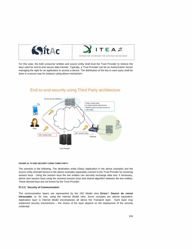
104
For this case, the both consumer entities and source entity shall trust the Trust Provider to retrieve the
keys used for end-to-end secure data transfer. Typically, a Trust Provider can be an Authorization Server
managing the right for an application to access a device. The distribution of the key to each party shall be
done in a secure way for instance using above mechanism.
Daisy Donald
Trust Provider
Service Access Platform
Gateway
End-to-end security using Third Party architecture
Get session keysGet sessions keys
Using session keysFor data transfer (the Service Platform does not have access to clear data)
FIGURE 15. TO END SECURITY USING THIRD PARTY.
The scenario is the following. The destination entity (Daisy Application in the above example) and the
source entity (Donald Device in the above example) separately connect to the Trust Provider for receiving
session keys. Using the session keys the two entities can securely exchange data and, if necessary,
derive new session keys using the received session keys and shared algorithm between the two entities.
These derived keys are not known by the Trust Provider.
57.2.2. Security of Communication
The communication layers are represented by the ISO Model view Erreur ! Source du renvoi
introuvable. or, for now, using the Internet Model view. Some concepts are almost equivalent.
Application layer is Internet Model encompasses all above the Transport layer. Each layer may
implement security mechanisms – the choice of the layer depend on the deployment of the security
credential.

105
57.2.2.1. Security at Network Layer
On the network layers, the source and destination hosts can be located on different network. In
consequence, this layer shall support addressing and routing mechanisms. The well known protocol is the
Internet Protocol. This layer relies on Data Link layer for transmitting data on each network. The studied
network stacks is based on EAP which is the most used stack in M2M environment. IPSEC Erreur !
Source du renvoi introuvable. is mainly used to setup Virtual Private Network for Corporate
Environment.
57.2.2.1.1. EAP
Description
EAP stands for “Encapsulated Authentication Protocol”. Typically EAP runs over Data Link Layer –
.e.g. PPP - and does not require by itself Internet Protocol. It is designed for use in network access
authentication. EAP has been designed to support many authentication methods by delegating
authentication to back-end authentication server. In this case, authenticator runs as a pass-through
authenticator – this is the typical architecture.
The EAP typical architecture is the following: a specific EAP method is carried over EAP which is itself
carried over Lower Link Layer
EAP method EAP method EAP method EAP method
EAP EAP EAP EAP
PP Lower Layer PP Lower Layer AAA Lower
Layer
AAA Lower Layer
Peer Pass-through Authenticator Auth Server
PP for Peer to Pass-through Authenticator link: example PPP, PANA Erreur ! Source du renvoi
introuvable.
AAA for Authenticator to Auth Server link: example Radius , Diameter

106
The generic EAP Protocol is the following:
1) The authenticator sends a Get- Identity request to the peer.
2) The peer responses with the peer identity.
3) The authenticator forwards the identity to the authentication server
4) The authentication server deducts from the identity the authentication method to apply.
5) Thru the Authenticator, the peer and authentication server exchange authentication messages
according the selected authentication method (see details descriptions of EAP-XXX methods).
6) On successful completion of the authentication, the Authenticator receives Master Session Key
(MSK) from the Authentication Server and allows access to the peer. The MSK is computed by the
EAP-XXX method and shall be - at least - 64 bytes long. The protocol to transport MSK from
authentication server to authenticator is out-of-scope EAP specifications.
7) Peer to authenticator messages are exchanged using a Transient Session Key derived from MSK.
The derivation mechanism depends on Peer To Authenticator protocol and shall be independent
of EAP-Method (separation of authentication and data protection) and is handled by the lower
layer protocol – IEEE 802.1X-2004, PPP, IKEv2, IEEE 802.11, PANA….
The 3 main methods are EAP-SIM, EAP-AKA and EAP-TLS.
EAP-SIM Erreur ! Source du renvoi introuvable. is an authentication method that uses the
authentication engine of a SIM card (A3/A8 algorithm, IMSI/Ki) and the authentication infrastructure of
a telecom operator (HLR) to prove user's identity. With EAP-SIM, the supplicant's functionalities are
split between the user's device and the SIM card, the authentication server is a Radius server
delegating authentication to the HLR.
EAP-SIM implements mutual authentication and replay protection above the 2G authentication
algorithm.
EAP-AKAErreur ! Source du renvoi introuvable. is based on the same principle than EAP-SIM
except that it uses 3G authentication algorithm (Authentication and Key Agreement, usually called
"milenage") instead of 2G one (A3/A8). In this case mutual authentication and replay protection are
"natively" supported by the authentication algorithm. Similar to EAP-SIM, EAP-AKA specifies an EAP-
based mechanism for mutual authentication and session key agreement using the Authentication and
Key Agreement (AKA) mechanism used in the Third Generation (3G) mobile networks (UMTS and
CDMA2000). AKA is based on symmetric keys and runs on any type of smart cards, e.g. USIM card.
EAP-Transport Layer Security (EAP-TLS) Erreur ! Source du renvoi introuvable. is an IETF open
standard. The security of the TLS protocol is strong, as long as the user understands potential
warnings about false credentials. It uses PKI to secure communication to the RADIUS authentication
server or another type of authentication server.
EAP-TLS is the original standard wireless LAN EAP authentication protocol. The highest security
available is when the client-side keys are housed in smartcards. This is because there is no way to
107
steal a certificate's corresponding private key from a smartcard without stealing the smartcard itself. It
is significantly more likely that the physical theft of a smartcard would be noticed (and the smartcard
immediately revoked) than a (typical) password theft would be noticed.
Security Summary
The Key Agreement depends on the method. Mutual Authentication between peer and Authentication
Server is optional and depends on the implemented EAP-method.
In case the Authenticator is separate from the backend authentication server, the security analysis is
more complicated as the peer authenticates the authentication server but not the authenticator. Case
by case security analysis shall be provided – it is out-of-scope EAP specification.
57.2.2.2. Security at Transport Layer
The Transport Layer implements reliability of data transmission over the network link. TCP and UDP –
even not fully consistent with L4 - ISO specification – are the most well-know protocols used at this level.
The Transport Layer may support security of the data transmission.
We describe here SSL/TLS which is the most used implementation of Security at Transport Layer over
TCP and DTLS over UDP.
57.2.2.2.1. SSL/TLS
Description
Transport Layer Security Erreur ! Source du renvoi introuvable. is a major protocol securing
communications on the Internet. The earlier version of the protocol was called Secure Sockets Layer
(SSL). TLS is currently supported by the IETF and is described in Erreur ! Source du renvoi
introuvable. (TLSv1.2) published in 2008. Basically, TLS builds a secure tunnel through the network
between two hosts. Data packets are encrypted so that only the specified receiver can access the content
to prevent eavesdropping, tampering, or message forgery.
TLS is based on several principles that led to his popularity and current massive usage to secure Internet
communications for client/server applications: the server is authenticated, the integrity and confidentiality
of data are proven thanks to the encrypted session, application data are transparently transferred
(application independent), and client authentication is possible if needed.
To provide privacy and data integrity, TLS is based on two protocols: TLS Record and TLS Handshake
protocol. TLS Record provides connection security and the TLS Handshake performs the authentication.
First, the TLS Handshake Protocol allows the client and the server to authenticate each other and to
negotiate the secret that will be used to generate the symmetric keys used to specifically secure the
communication. Server authentication is done through public key cryptography and relies mostly on the
usage of a certification authority (CA).
The TLS Handshake Protocol process includes two phases:

108
Server Authentication in which the client requests the server’s certificate. In response, the server
returns its digital certificate and signature to the client. The server certificate provides the server’s
public key. The signature proves that the server currently has the private key corresponding to the
certificate.
Client Authentication (optional) in which the server requests the client’s certificate. In response, the
client sends the digital certificate and signature to the server.
The secret is securely negotiated so that a man in the middle attack (eavesdropping) cannot obtain it;
neither modifies the negotiation without being detected. The two parties also negotiate the encryption
algorithm to be used as presented in Figure 8 – step 1 and 2. Once set, symmetric cryptographic keys are
generated (step 7) based on the shared secret and further communications are private.
FIGURE 16. SSL HANDSHAKE FROM ORACLE® FUSION MIDDLEWARE ADMINISTRATOR'S GUIDE.
We can see that TLS protocol uses a combination of public-key (step 5) and symmetric key encryption
(step 9). In fact, symmetric key encryption is much faster than public-key encryption, but public-key

109
encryption is needed to provide authentication techniques. The handshake allows the server to
authenticate it to the client using public-key techniques, and then allows the client and the server to
cooperate in the creation of symmetric keys used for rapid encryption, decryption, and tamper detection
during the session that follows. Optionally, the handshake also allows the client to authenticate itself to
the server.
Then, the TLS Record Protocol encapsulates the application data and securely transports it. It relies on
symmetric cryptography using previously generated keys for data encryption and is totally application
independent. Message integrity can be checked by adding a keyed MAC which is generated by a hash
function.
TLS provides the following security functions:
Data Encryption to ensure data security and privacy. Both public key and secret key encryption are
used to achieve maximum security. All traffic between a TLS server and TLS client is encrypted using
both public key and secret key algorithms. Encryption thwarts the capture and decryption of TCP/IP
sessions.
Data Integrity to ensure that TLS session data is not manipulated en route. TLS uses hash functions
to provide the integrity service.
Mutual Authentication to verify the identities of the server and, on server request, may require client
authentication. Identities are digital certificates. The entity presenting the certificate must digitally sign
the data to prove ownership of the certificate. The combination of the certificate and signature
authenticates the entity.
Security Summary
- TLS secures the link from eavesdroppers but if the host is directly compromised, TLS cannot secure
the communication
- Some older version of SSL/TLS can still use cryptographic algorithms that are proven breakable
Using TLS in constrained objects.
- If the client needs to be authenticated to the server, the technology requires complex and huge
deployment process of client certificates and therefore it is not well suited for M2M. The CA must be
trustworthy and is a single point of failure in the system. It is not suited to secure pervasive and peer-
to-peer M2M communications. Moreover, the required bandwidth and resource consumption have not
been optimized for M2M communications with strict constraints (generally, the client authentication is
based on RSA technology which is time and CPU consuming).
- However, message encryption and integrity is performed using symmetric cryptography (for example:
AES) which is well suited for IoT objects.
57.2.2.2.2. DTLS
Description

110
The DTLS Erreur ! Source du renvoi introuvable. protocol provides communications privacy for
datagram based networks. It is almost similar to TLS, with important modifications to be compliant with
datagram transport.
The TLS cannot be applied directly in datagram environments, reason that packets may be lost or
reordered during transmissions. During handshake of TLS, all messages are follows defined order for
transmitting and receiving whereas in DTLS it is not. TLS has no built in facilities to handle this kind of
unreliability, and therefore TLS implementations are not suitable for datagram transport directly. DTLS
uses a simple retransmission timer to handle packet loss. Some design requirements were mentioned
from Erreur ! Source du renvoi introuvable., which are summarized as follows,
1. Datagram Transport
DTLS must be capable of handling complete key negotiation and data transfer over a single datagram
channel.
2. Reliable Session Establishment
As DTLS runs entirely over unreliable datagram transport, a reliable key establishing and secure
negotiation should be performed. It must implement a retransmission mechanism for ensuring that
handshake messages are reliably delivered.
3. Security Services
DTLS must maintain confidentiality and integrity for the data transmitted over it.
DTLS Handshake Protocol
The DTLS handshake is almost similar to TLS with minor adaptations. Because the DTLS handshake
operated over datagram transport, it is vulnerable to two denials of service attacks that TLS is not. The
first attack is the standard resource consumption attack. The second attack is an amplification attack
where the attacker sends a Client Hello message apparently sourced by the victim. The server then
sends a Certificate Message - which is much larger to the victim. To mitigate such attacks, DTLS added
following changes in its handshake protocol as compared to TLS Handshake,
1. Stateless cookie exchange to prevent denial of service.
2. Reliability maintained by means of modifying the handshake header to handle message loss,
reordering, and fragmentation.
3. Retransmission timers to handle message loss.
In DTLS, during transmissions messages may get lost, re ordered or modified. Clearly, this is
incompatible with TLS handshake. Messages may larger than any given datagram, thus creating the
problem of fragmentation. DTLS provides following fixes for these problems.
Packet Loss
DTLS uses a simple retransmission timer to handle packet loss.

111
Reordering
In DTLS, a specific sequence number assigned to each handshake message within that handshake.
When a peer receives a handshake message, it can quickly determine whether that message is the next
message it expects. If it is, then it processes it. If not, it queues it up for future handling once all previous
messages have been received.
Fragmentation
Each DTLS handshake message may be fragmented over several DTLS records. Each DTLS
handshake message contains both a fragment offset and a fragment length. Thus, a recipient in
possession of all bytes of a handshake message can reassemble the original un fragmented message.
DTLS Record Layer
The DTLS record layer is very close TLS 1.1. The only change is the inclusion of an explicit sequence
number and Epoch number in the record. This sequence number allows the recipient to correctly verify
the DTLS MAC. Epoch numbers are also used by endpoints to determine which cipher state has been
used to protect the record payload.
Security Summary
- DTLS includes a cookie exchange designed to protect against denial of service.
- Reliable transmissions are achieved by implementing suitable packet loss handling mechanisms, re
ordering techniques.
Using DTLS in constrained objects.
Message encryption and integrity is often performed using symmetric cryptography (for example: AES)
which is well suited for IoT objects that does not have huge deployment issue. DTLS is designed to IoT
object because it is based on UDP protocol. It is often used to transport COAP protocol.
57.2.2.3. Security at Application Layer
In case the lower layer security is not sufficient and/or cannot be exploited at application level, it could be
necessary to implement security at application level. It is particularly the case when, application provider
cannot rely on single security environment but has to integrate security implemented by other security
providers. The rational can be the cost of the deployment of the security credential, the ease of uses the
partner technologies and solutions particularly when the required technology is provided by bug actors of
the market (FaceBook, Google,).
57.2.2.3.1. SAML 2.0
Description
SAML Erreur ! Source du renvoi introuvable.Erreur ! Source du renvoi introuvable. stands for
Security Assertion Markup Language and is issued by the OASIS standard in 2005. This is a XML-based
framework for federated identity management. SAML is used by many systems like Liberty/Kantara

112
Framework Erreur ! Source du renvoi introuvable. and Microsoft Cardspace Erreur ! Source du
renvoi introuvable..
SAML specification allows token specification as well as exchange protocol. Different usages are
specified – each binding correspond to a SAML Profile. The most famous on is the “SAML Web Browser
SSO Profile”.
SAML Web Brower SSO Profile. In this Profile, the SAML assertion encompasses the Identity data.
Other profile may expose only an artifact that shall be used to retrieve the Identity at the Identity Provider.
SP: the service provider
IdP: the identity provider
The SAML 2.0 standard is able to support either “identity federation” paradigm or “claim based identity”
paradigm. The SAML assertion shall be signed with the private key of the IdP. It contains information
about the user according the schema on which it is applied.
Security Summary
User SP
Requests access
Sends back SAML
request and redirects
To IdP
SAML request
User authentication (if needed for
supporting SSO)
SAML response
SAML assertion
User is logged
IdP
FIGURE 17. SAML TRANSACTION.
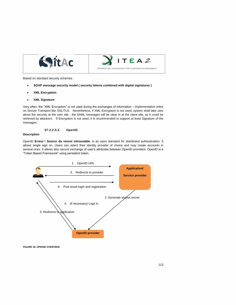
113
Based on standard security schemes :
SOAP message security model ( security tokens combined with digital signatures )
XML Encryption
XML Signature
Very often, the “XML Encryption” is not used during the exchanges of information – implementation relies
on Secure Transport like SSL/TLS. Nevertheless, if XML Encryption is not used, system shall take care
about the security at the user site - the SAML messages will be clear in at the client site, so it could be
retrieved by attackers. If Encryption is not used, it is recommended to support at least Signature of the
messages.
57.2.2.3.2. OpenID
Description
OpenID Erreur ! Source du renvoi introuvable. is an open standard for distributed authentication. It
allows single sign on. Users can select their identity provider of choice and may create accounts in
several ones. It allows also secure exchange of user’s attributes between OpenID providers. OpenID is a
“Token Based Framework” using persistent token.
Application/
Service provider
OpenID provider
1. OpenID URL
2. Generate shares secret
4. (if necessary) Logs in
5. Redirects to application
3. Redirects to provider
6. Post result login and registration info (token)
FIGURE 18. OPENID OVERVIEW.
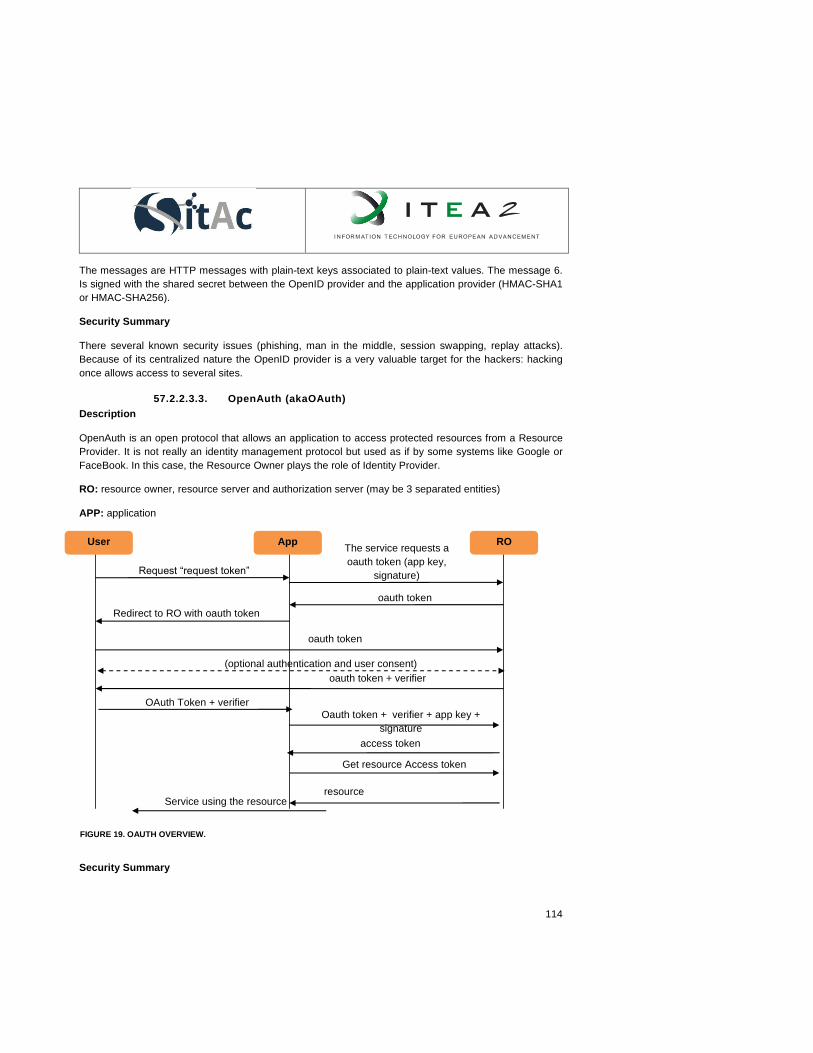
114
The messages are HTTP messages with plain-text keys associated to plain-text values. The message 6.
Is signed with the shared secret between the OpenID provider and the application provider (HMAC-SHA1
or HMAC-SHA256).
Security Summary
There several known security issues (phishing, man in the middle, session swapping, replay attacks).
Because of its centralized nature the OpenID provider is a very valuable target for the hackers: hacking
once allows access to several sites.
57.2.2.3.3. OpenAuth (akaOAuth)
Description
OpenAuth is an open protocol that allows an application to access protected resources from a Resource
Provider. It is not really an identity management protocol but used as if by some systems like Google or
FaceBook. In this case, the Resource Owner plays the role of Identity Provider.
RO: resource owner, resource server and authorization server (may be 3 separated entities)
APP: application
Security Summary
User App RO
Request “request token”
oauth token
oauth token
The service requests a
oauth token (app key,
signature)
Redirect to RO with oauth token
oauth token + verifier
Oauth token + verifier + app key +
signature
access token
OAuth Token + verifier
Get resource Access token
(optional authentication and user consent)
resource Service using the resource
FIGURE 19. OAUTH OVERVIEW.

115
Used as an identification protocol, the security of this protocol is very weak because one can reuse an
access token obtained for a given application to log into another one. Security relies completely on the
HTTPS protocol. Nevertheless, OAuth is vulnerable to several known attacks :
Network eavesdropping
Cross-site scripting
Impersonation and session swapping
Cross-site request forgery
Even OAuth does not strictly specify the format the “access token”, it is often related to the resource itself
and is not linked to the application that requested the token.
57.2.2.3.4. Generic Bootstrapping Architecture - GBA
Description
GBA Erreur ! Source du renvoi introuvable. standard provides an application free mechanism able to
build a shared secret between a user agent (generally running on a mobile phone) and a server. This
shared secret enables client-server authentication. GBA relies on 3GPP AKA Erreur ! Source du
renvoi introuvable. (Authentication and Key Agreement) used in 3G networks (USIM application), and
also used in IMS infrastructure. GBA may also rely on 2G network infrastructure via ISIM application.
The GBA components are the following:
UE (User Equipment). It is generally the user mobile phone and its SIM card.
NAF (Network Access Function): the service provider the user would like to reach.
BSF (Bootstrapping Server Function) : the MNO server is able to build the GBA shared secret
between the User Agent and the NAF. The BSF relies to HSS (Home Subscriber System) : MNO
server. The server describes the user’s subscription in its home network. It enables to specify, User
identities, Registration data and Access parameter

116
FIGURE 20. GBA ARCHITECTURE.
The User Equipment authenticated to the BSF using AKA protocol. BSF relies on HSS to perform the
SIM card authentication. On completion, UE and BSF derive a session key. When the UE wants to
reach a NAF, UE via the SIM application derives a new key (computed using NAF identifiers). The NAF
requests the UE-NAF key to the BSF and the NAF is now able:
1) to check the UE is a valid one
2) to establish a secure communication with the UE.
Security Summary
Mutual Authentication of Card and BSF
Mutual Authentication of BSF and NAF.
The Card does not authenticates the NAF, but the NAF is able to check the UE is a valid one
NAF-UE Confidentiality: Link Layer can use GBA generated encryption key
NAF-UE Integrity : Link Layer can use GBA generated MAC key
Conclusions
SP=NAF
GBA/Ua (HTTP/S)
PLMN
UE (mobile phone)
BSF HSS
GBA/Zh (Diameter)
GBA/Ub (HTTP/S) GBA/Zn (Diameter, HTTP/S)
117
The security and privacy state-of-the-art highlights many difficulties to support security in M2M solutions.
The issues concern the deployment of the security credentials on M2M device; the constraints according
the CPU and memory required for algorithm implementation and the security of the storage of the
credentials at low cost. The easy-of-use of the security protocols for consuming application and according
the implementation at the device is one the major problem for enabling security in real deployment of
M2M solutions.
SITAC will explore such issues and will propose some solutions.
References
[1] ISO/IEC 7498-1 http://www.iso.org/iso/fr/catalogue_detail.htm?csnumber=20269
[2] IPSEC http://www.ietf.org/rfc/rfc2401.txt
[3] EAP-SIM and EAP-AKA
http://www.3gpp.org/ftp/tsg_sa/WG3_Security/TSGS3_25_Munich/Docs/PDF/S3-020549.pdf
[4] OpenID 2.0 http://openid.net/specs/openid-authentication-2_0.html
[5] EAP-TLS http://tools.ietf.org/html/rfc5216
[6] TLS - http://tools.ietf.org/html/rfc5246
[7] DTLS - E. Rescorla; N. Modadugu, "Datagram Transport Layer Security". IETF RFC 4347 - April
2006
[8] OASIS, “Security and Privacy Considerations for the OASIS Security Assertion Markup Language
(SAML) V2.0”, OASIS Standard, 15 March 2005, http://docs.oasis-open.org/security/saml/v2.0
[9] Liberty Framework http://www.projectliberty.org/specs/ and Kantara http://kantarainitiative.org/
[10] Windows/Microsoft CardSpace http://msdn.microsoft.com/en-us/library/aa480189.aspx
[11] PCI-DSS 2.0 Requirements and Security Assessment Procedures
https://www.pcisecuritystandards.org/documents/pci_dss_v2.pdf
[12] GBA http://www.3gpp.org/ftp/Specs/archive/33_series/33.220
[13] PANA - http://tools.ietf.org/html/rfc5191