state of connecticut cross connection control …
TRANSCRIPT

STATE OF CONNECTICUT
CROSS CONNECTION CONTROL MANUAL
Prepared by:
The State of ConnecticutDepartment of Public Heal
Drinking Water Division410 Capitol Avenue, MS #51 W
P.O. Box 340308 Hartford, Connecticut 06134-
and
Connecticut Section – American Water WCross Connection Control Com
Fifth Edition January 2003
Table of Contents
th
AT
0308
orks Association, mittee

Page ii
1 PREFACE............................................................................................................................................1
2 DEFINITIONS ....................................................................................................................................3
3 REGULATIONS OF CONNECTICUT STATE AGENCIES ............................................................5
4 DEVICES………………………………………………………………………………………… ..11
4.1 AIR GAP .................................................................................................................................11 4.1.1 Introduction ..........................................................................................................11 4.1.2 Operation .............................................................................................................11 4.1.3 Installation ...........................................................................................................11 4.1.4 Uses ......................................................................................................................11 4.2 ATMOSPHERIC VACUUM BREAKER .........................................................................................13 4.2.1 Introduction ..........................................................................................................13 4.2.2 A.S.S.E. And/Or AWWA Standard........................................................................13 4.2.3 Operation .............................................................................................................13 4.2.4 Installation ...........................................................................................................14 4.2.5 Uses ......................................................................................................................14 4.3 HOSE BIBB VACUUM BREAKERS .............................................................................................15 4.3.1 Introduction ..........................................................................................................15 4.3.2 A.S.S.E. And/Or AWWA Standard........................................................................15 4.3.3 Operation .............................................................................................................15 4.3.4 Installation ...........................................................................................................15 4.3.5 Uses ......................................................................................................................15 4.4 LABORATORY VACUUM BREAKERS..........................................................................................16 4.4.1 Introduction ..........................................................................................................16 4.4.2 A.S.S.E. And/Or AWWA Standard ........................................................................16 4.4.3 Operation .............................................................................................................17 4.4.4 Installation ...........................................................................................................17 4.4.5 Uses ......................................................................................................................17 4.5 PRESSURE VACUUM BREAKER ................................................................................................18 4.5.1 Introduction ..........................................................................................................18 4.5.2 A.S.S.E. And/Or AWWA Standard ........................................................................18 4.5.3 Operation .............................................................................................................18 4.5.4 Installation ...........................................................................................................19 4.5.5 Uses ......................................................................................................................19 4.5.6 Field Testing.........................................................................................................19 4.5.6.1 Troubleshooting...............................................................................21 4.6 SPILL-RESISTANT PRESSURE VACUUM BREAKER....................................................................22 4.6.1 Introduction ..........................................................................................................22 4.6.2 A.S.S.E. And/Or AWWA Standard ........................................................................22 4.6.3 Operation .............................................................................................................22 4.6.4 Installation ...........................................................................................................22 4.6.5 Uses ......................................................................................................................23 4.6.6 Test Procedure for Spill Resistant Vacuum Breaker ............................................23 4.7 INTERMEDIATE AIR VENT TYPE BACKFLOW PREVENTER ...........................................................24 4.7.1 Introduction ..........................................................................................................24 4.7.2 A.S.S.E. And/Or AWWA Standard........................................................................24 4.7.3 Operation .............................................................................................................24 4.7.4 Installation ...........................................................................................................25 4.7.5 Uses ......................................................................................................................25

Page iii
4.8 AIR VENT TYPE BACKFLOW PREVENTER FOR BEVERAGE MACHINE CARBONATORS.................25 4.8.1 Introduction ..........................................................................................................25 4.8.2 A.S.S.E. And/Or AWWA Standard........................................................................25 4.8.3 Operation .............................................................................................................26 4.8.4 Installation ...........................................................................................................26 4.8.5 Uses ......................................................................................................................26 4.9 DOUBLE CHECK VALVE ASSEMBLY.........................................................................................27 4.9.1 Introduction ..........................................................................................................27 4.9.2 A.S.S.E. And/Or AWWA Standard........................................................................27 4.9.3 Operation .............................................................................................................27 4.9.4 Installation ...........................................................................................................28 4.9.5 Uses ......................................................................................................................28 4.9.6 Field Testing.........................................................................................................28 4.9.6.1 Test Procedure..................................................................................29 4.9.6.2 Troubleshooting................................................................................31 4.10 REDUCED PRESSURE PRINCIPLE BACKFLOW PREVENTERS.....................................................31 4.10.1 Introduction..........................................................................................................31 4.10.2 A.S.S.E. And/Or AWWA Standard........................................................................31 4.10.3 Operation ..........................................................................................................32 4.10.4 Installation of RP Devices....................................................................................32 4.10.5 Uses ........... ..........................................................................................................32 4.10.6 Maintenance .........................................................................................................33 4.10.7 Maintenance of Large RP Devices .......................................................................33 4.10.8 Field Testing.........................................................................................................35 4.10.8.1 Test Procedure..................................................................................35 4.10.8.2 Troubleshooting................................................................................37 4.11 TRAP PRIMER.............. ..........................................................................................................38 4.11.1 Introduction..........................................................................................................38 4.11.2 A.S.S.E. And/Or AWWA Standard........................................................................38 4.11.3 Operation ..........................................................................................................38 4.11.4 Installation ..........................................................................................................38 4.12 EQUIPMENT REVIEW LIST.......................................................................................................39
5 TESTING PROGRAM......................................................................................................................40 5.1 BACKFLOW CERTIFICATION CATEGORIES...............................................................................40 5.2 DIFFERENTIAL PRESSURE GAUGE ..........................................................................................41 5.3 RECORD KEEPING..................................................................................................................42 5.3.1 Cross Connection Sample Inspection Form.........................................................43 5.3.2 Cross Connection Annual Test Sample Report ....................................................44 5.3.3 Cross Connection Survey Report Form Instructions............................................45 5.3.4 Cross Connection Survey Report Form................................................................46 5.3.5 Cross Connection Survey Report Form for Small Systems ..................................47 5.3.6 Cross Connection Sample Inspection Procedure .................................................48 5.3.7 Violation Letter ....................................................................................................50 5.3.8 No Violations Found Letter..................................................................................51 5.3.9 Compliance Letter ................................................................................................52 5.3.10 Letter of Transmittal.............................................................................................53 5.3.11 Annual Testing Notification Letter .......................................................................54 5.3.12 Annual Testing Final Notice Letter ......................................................................55

Page iv
6 FACILITIES TO BE INSPECTED ...................................................................................................56 6.1 COMMON INSTALLATIONS.......................................................................................................56 6.1.1 Boilers ....... ..........................................................................................................56 6.1.2 Fire Sprinkler Systems..........................................................................................57 6.1.3 Irrigation/Lawn Sprinkler Systems.......................................................................57 6.1.4 Toilets or Urinals .................................................................................................57 6.1.5 Hose Connections.................................................................................................57
6.1.6 Air Conditioning Units, Heat Exchanges and Other Water Cooled Equipment ..57 6.1.7 Auxiliary Sources .................................................................................................58 6.2 FACILITY INSPECTIONS...........................................................................................................58 6.2.1 Sewage Plants, Pump Stations and Water Reduction Facilities ..........................58 6.2.2 Plating and Chemical Companies ........................................................................58 6.2.3 Hospitals.... ..........................................................................................................59 6.2.4 Convalescent and Nursing Homes .......................................................................59 6.2.5 Funeral Homes and Mortuaries ...........................................................................59 6.2.6 Schools and Universities ......................................................................................59 6.2.7 Medical Laboratories ...........................................................................................60 6.2.8 Car Wash Facilities..............................................................................................60 6.2.9 Animal Hospitals, Grooming Establishments.......................................................60 6.2.10 Potable Water Tanks ............................................................................................60 6.2.11 Marinas, Yacht Clubs and Docks .........................................................................60 6.2.12 Swimming Pools ...................................................................................................61 6.2.13 Greenhouses .........................................................................................................61 6.2.14 Tank Trucks and Sprayers....................................................................................61 6.2.15 Automobile or Radiator Repair Facilities............................................................61 6.2.16 Photo Developers .................................................................................................62 6.2.17 Laundries, Dry Cleaners, and Dye Works ...........................................................62 6.2.18 Solar Heating Systems..........................................................................................62 6.2.19 Food Processing Such as Bottling Companies, Canneries & Meat Packing.......62 6.2.20 Beauty Salons – Barber Shops – Beauty Schools.................................................62 6.2.21 Doctor’s and Dentist’s Offices .............................................................................63 6.2.22 Restaurants and Food Establishments .................................................................63 6.3 EQUIPMENT TO BE INSPECTED ...............................................................................................64
7 REGULATORY CLARIFICATION LETTERS AND STATEMENT ............................................66 7.1 Regulatory Clarification - Section 19-13-B38a(c)(1) of the RCSA ......................................66 7.2 Regulatory Clarification - Section 19-13-38a (c)(1) of the RCSA........................................68 7.3 Trap Primers – Regulation Clarification .............................................................................69 7.4 Contaminated Private Well – Regulation Clarification .......................................................70 7.5 Washing Machines – Regulation Clarification.....................................................................71 7.6 Letter – Intermediate Air Vent Backflow Preventer .............................................................73 7.7 Home Booster Pumps – Recommended Procedure ..............................................................74 7.8 Make-Up Water Line Recommended Procedure ..................................................................75 7.9 Enforcement of Cross Connection Control Regulations – Guidance Document..................76 7.10 Interruption of Water Supply – Guidance Document ...........................................................78 7.11 Backflow Prevention at Dental Offices – Fact Sheet............................................................80
8 CASE HISTORIES……………………………………………………………………………………82
9 APPENDIX........................................................................................................................................................... 9.1 APPENDIX A – TECHNICAL INFORMATION ON FIRE SPRINKLER REGULATIONS……………………84
9.2 Appendix B – Plumbing Hazards& Cross Connections in Food Establishments ........................85

Page 1
1 PREFACE This manual is provided as a guidance to the water purveyor. The water purveyor may have requirements which exceed the regulations as stated in this manual. What are cross connections and why are we concerned about them? A cross connection is a connection between a potable water system and a non-potable system. It can lead to contamination of a public water system with the results ranging from an aesthetic problem to illness or death and possible lawsuits. There are many case histories, some of which are discussed in this manual, which illustrate that the need for cross connection control is based on more than theory. A cross connection can be either direct or indirect. A direct connection is one where an actual physical connection exists such as a line to a chemically treated boiler or a bypass around a backflow prevention device. An indirect connection is one where the potential exists for a connection to be created such as a garden hose which can be submerged in a bucket of soapy water or connected to a pesticide sprayer. Contamination will result when a cross connection exists and backflow or a reversal of flow occurs. There are two types of backflow: backsiphonage and back pressure. Backsiphonage results when there is a negative pressure in the system and the contaminant is pulled into the drinking water supply. This can be caused by such items as a main break or large fire demand. Back pressure occurs when the pressure on the non-potable system is greater than the potable system and the contaminant is pushed into the drinking water system. This can be caused by such items as a boiler or pump in the distribution system. Protection of the drinking water and the water distribution system is possible only through regular surveillance by inspectors who are knowledgeable and experienced in piping installations. Without such knowledge and experience, it will be impossible to detect and eliminate cross connections. Because plumbing systems are continually being installed, altered, or extended, continuous inspections and re-inspections are required to insure against the danger of a cross connection. The Cross Connection Control Manual has been prepared by the Department of Public Health (DPH) Drinking Water Division (DWD) with the assistance of the Cross Connection Control Committee of Connecticut Section of the American Water Works Association to help inspection officials who are responsible for the safety of the water supply within the distribution system. The manual will aid in defining the legal requirements of surveillance, delineate the procedures, identify the problem areas and possible points of contamination, provide types of equipment available for use to aid in protecting a water supply distribution system and list sources of other information available for more detailed study in this area. Members of the Cross Connection Control Committee who worked on the preparation of the manual are listed below:
Gregg Bassetti Norwich Water Department Patrick Bernardo Mashantucket Pequot Tribal Nation Tom Caliolo, Sr. Waterbury Water Department Al D’Amato Bristol Water Department Tom Ferlazo Manchester Water Department Barry Fontaine Southington Water Department Edward Forcier Norwalk Second Taxing District Water Department Ray Foster Connecticut Water Company John Gabor Aquarion Water Company of Connecticut David Gagliardi New Britain Water Department Mark A. Hanson Metropolitan District Commission

Page 2
Ed Harper Mashantucket Pequot Tribal Nation Jim Hatcher Groton Department of Utilities Dave Kuzminski Portland Water Department Bob Malouf Norwich Public Utilities Mike Martello Aquarion Water Company of Connecticut Joe Mrozowski Wallingford Department of Public Utilities Ted O’Donnell Waterbury Water Department Robert Rivard Dept. of Public Health, Drinking Water Division John Scasino South Central CT Regional Water Authority Pete Sweeney Bethel Water Department Anthony West Meriden Water Department Michael Witek Birmingham Utilities
Backflow of harmful liquids into a drinking water system can occur very easily unless officials responsible for such inspections become very familiar with the contents of this manual and supplement that knowledge with attendance at seminars and training sessions. This manual shows schematic diagrams of backflow prevention equipment and procedures of field testing such installations. Sections herein delineate the type of consumers requiring inspection, suggested inspection forms, record keeping and other information necessary for a cross connection control program. The manual will enable the user to outline a cross connection control program and to show the magnitude and frequency of inspections required to comply with the Regulations of Connecticut State Agencies (RCSA).

Page 3
2 DEFINITIONS Air gap - The unobstructed vertical distance through the free atmosphere between the lowest opening from any
pipe or outlet supplying water to a tank, plumbing fixture, or other device and the flood level rim of the receptacle. The vertical physical separation shall be at least two times the inside diameter of the water inlet pipe above the flood rim level but shall not be less than one inch.
Air vent type backflow preventer - A device containing two independently operating check valves separated by
a chamber which can automatically vent to the atmosphere if backflow occurs. Approved water supply - A water supply which is monitored by the State Department of Public Health as a
public water system. Atmospheric vacuum breaker - A mechanical device which automatically air vents a pipeline to prevent
backsiphonage. Backflow - The reverse flow of any liquid or substance in the distributing pipes of a public water supply. Backpressure - Backflow resulting from pressures greater than the public water supply pressure. Backflow prevention device tester, certified - A person who has completed and passed a course on the testing of
backflow prevention administered or approved by the Department of Public Health. Backsiphonage - Backflow resulting from negative pressures in the distributing pipes of a public water supply. Contamination - Any physical, chemical, biological or radiological foreign substance that tends to degrade water
quality so as to constitute a hazard or to impair its usefulness. Cross Connection – An actual or potential connection between a public water system and any other source or
system through which it is possible to introduce into the water system any contamination or polluting agent.
Cross Connection Survey Inspector – A person who has completed and passed a course on cross connection
inspections administered or approved by the Department of Public Health. Degree of Hazard - The evaluation of a health, system, plumbing or pollutional hazard. Double check valve assembly (DCVA) - A device which contains two independently acting check valves located
between two tightly closing shut-off valves and fitted with properly located test cocks. Fire Sprinkler System - An integrated system of underground and overhead piping designed to provide fire
protection for a building or structure. The installation includes one or more automatic water supplies. The portion of the sprinkler system aboveground is a network of specially sized or hydraulically designed piping installed in a building, structure, or area generally overhead, and to which sprinklers are attached in a systematic pattern. The valve controlling each system riser is located in the sprinkler riser or its supply piping. Each sprinkler system riser includes a device for actuating an alarm when the system is in operation. The system is usually activated by heat from a fire and discharges water over the fire area.

Page 4
Hose bibb vacuum breaker - An atmospheric vacuum breaker designed to be attached to an outlet having a hose
connection thread. Industrial fluids - Any fluid or solution which may be chemically, biologically or otherwise contaminated or
polluted in a form or concentration such as would constitute a health, system, pollutional or plumbing hazard if introduced into an approved water supply. This may include, but not be limited to: polluted or contaminated used waters; all types of process waters and "used waters" originating from the public potable water system which may deteriorate in sanitary quality; chemicals in fluid form; plating acids and alkalies; circulated cooling waters connected to an open cooling tower and/or cooling waters that are chemically or biologically treated or stabilized with toxic substances; contaminated natural waters such as from wells, springs, streams, rivers, bays, harbors, seas, irrigation canals or systems, etc.; oils, glycerine, paraffines, caustic and acid solutions and other liquid and gaseous fluids used in industrial or other processes or for fire fighting purposes.
Owner - The customer of a public water system. Pressure vacuum breaker - A device which contains a spring loaded check valve and a spring loaded
atmospheric vent which opens when the pressure approaches atmospheric. The unit shall include two tightly closing shut-off valves located at each end of the device and two test cocks properly located for testing the device.
Reduced pressure principle backflow preventer - A device containing within its structure a minimum of two
independently acting, approved check valves, together with an automatically operating pressure differential relief valve located between the two check valves. The first check valve reduces the system pressure a predetermined amount so that during normal flow and a cessation of normal flow the pressure between the checks shall be less than the system pressure. In case of leakage of either check valve, the differential relief valve, by discharging to atmosphere, shall operate to maintain the pressure between the checks less than the system pressure. The unit shall include tightly closing shut-off valves located at each end of the device and each device shall be fitted with properly located test cocks.
Siamese Connection - An inlet equipped with one or more couplings to which a fire hose can be attached and
through which water can be delivered by a fire department pumper to a sprinkler system. Spill-Resistant Pressure Vacuum Breaker – A device which contains an internally loaded check valve and a
loaded air inlet valve opening to the atmosphere on the discharge side of the check valve between two resilient seated shutoff valves. The assembly includes one properly located resilient seated test cock, and one vent valve. The air inlet valve opens when the inlet pressure is 1 PSI or greater, and outlet pressure is atmospheric. The check valve is internally loaded and is designed to hold tight in the normal direction of flow with the inlet pressure at 1 PSI and the outlet under atmospheric pressure.
Sprinkler system - A plumbing system design to spray a water source for fire protection, irrigation or cooling. Submerged inlet - A public water supply pipe extending into a tank, vessel fixture or appliance where the liquid
level or overflow rim is higher than the inlet. Toxic or objectionable substance - Any compound which could affect the public health, the potability, or the
aesthetic quality of the water. Water utility - The owner or operator of a public water system.
Page 5
3 REGULATIONS OF CONNECTICUT STATE AGENCIES SECTION 19-13-B37. Cross Connections Between Water Supplies Prohibited No physical connection between the distribution system of a public water system and that of any other water supply shall be permitted, unless such other water supply is of safe sanitary quality and the interconnection of both supplies is approved by the State Department of Public Health. No officer, board, corporation or other person or group of persons, owning, managing or controlling any public water system, shall provide new water service to a site where any person, firm or corporation either maintains such connection or is not in compliance with section 19-13-B38a of the Regulations of Connecticut State Agencies at this location. Upon written order by the local health department or the Department of Public Health, an officer, board, corporation or other person or group of persons, owning, managing or controlling any public water system, shall terminate existing water service to a site where any person, firm or corporation either maintains such connection or is not in compliance with section 19-13-B38a of the Regulations of Connecticut State Agencies at this location. SECTION 19-13-B38a. Permissible Arrangements for Connections to Public Water Supply Lines (a) Definitions. As used in this section: (1) “Air gap” means the unobstructed vertical distance through the free atmosphere between the lowest
opening from any pipe or outlet supplying water to a tank plumbing fixture, or other device, and the flood level rim of the receptacle. The vertical physical separation shall be at least two times the inside diameter of the water inlet pipe above the flood rim level but shall not be less than one inch;
(2) “Air vent type backflow preventer” means a device containing two independently operating check
valves separated by a chamber which can automatically vent to the atmosphere if backflow occurs; (3) “Atmospheric vacuum breaker” means a mechanical device which automatically air vents a pipeline
to prevent backsiphonage;
(4) “Double check valve assembly” (DCVA) means a device which contains two independently acting check valves located between two tightly closing shut-off valves and fitted with properly located test cocks;
(5) “Fire sprinkler system” for fire protection purposes means an integrated system of underground and
overhead piping designed to provide fire protection for a building or structure. The installation includes one or more automatic water supplies. The portion of the sprinkler system above-ground is a network of specially sized or hydraulically designed piping installed in a building, structure, or area generally overhead, and to which sprinklers are attached in a systematic pattern. The valve controlling each system riser is located in the sprinkler riser or its supply piping. Each sprinkler system riser includes a device for actuating an alarm when the system is in operation. The system is usually activated by heat from a fire and discharges water over the fire area;
(6) “Hose bibb vacuum breaker” means an atmospheric vacuum breaker designed to be attached to an
outlet having a hose connection thread; (7) “Owner” means the customer of a public water system; (8) “Pressure vacuum breaker” means a device which contains a spring loaded check valve and a spring
loaded atmospheric vent which opens when the pressure approaches atmospheric. The unit shall include two tightly closing shut-off valves located at each end of the device and two test cocks properly located for testing the device;

Page 6
(9) “Reduced pressure principle backflow preventer” (RPD) means a device containing within its structure a minimum of two independently acting, approved check valves, together with an automatically operating pressure differential relief valve located between the two check valves. The first check valve reduces the system pressure a predetermined amount so that during normal flow and a cessation of normal flow the pressure between the checks shall be less than the system pressure. In case of leakage of either check valve, the differential relief valve, by discharging to atmosphere, shall operate to maintain the pressure between the checks less than the system pressure. The unit shall include tightly closing shut-off valves located at each end of the device and each device shall be fitted with properly located test cocks;
(10) “Siamese connection” means an inlet equipped with one or more couplings to which a fire hose can be
attached and through which water can be delivered by a fire department pumper to a sprinkler system; and
(11) “Toxic or objectionable substance” means any compound, which could affect the public health, the
potability, or the aesthetic quality of the water.
(b) Air Gap. An air gap is required between all potable water lines and equipment or systems, which may be subject to contamination.
(c) Reduced pressure principle backflow preventer.
(1) A reduced pressure principle backflow preventer (RPD) is required on a line to all facilities where
toxic or objectionable substances are used in addition to the required air gap, vacuum breaker or RPD on individual pieces of equipment unless the public water system has determined that an RPD is not necessary. Where such substances are used in a specific area, an RPD on the line to that area may be used in place of the RPD on the line to the facility.
(2) The owner shall install a reduced pressure principle backflow preventer (RPD) or an air gap in the
following instances:
(A) On a line to fire sprinkler systems (including tanks) where chemicals are added or to foam fire fighting systems;
(B) On a line to pressurized water systems on ships; (C) On a line used to supply car wash facilities where pressure is boosted; (D) On a line to irrigation or lawn sprinkler systems where chemicals are added; (E) On a line to all boiler systems where chemicals are added; (F) On a line to heat exchangers where chemicals are added; (G) On a line to solar heating systems where chemicals are added; (H) On a line to plating tanks or areas. No potable water use will be allowed downstream of the
device pursuant to section 19-13-B38a(e)(2) of the Regulations of Connecticut State Agencies.
(3) Unless otherwise required by sections 19-13-B38a(b) or 19-13-B38a(c) of the Regulations of Connecticut State Agencies, the owner shall install either an RPD or an air vent type backflow preventer or an air gap in the following instances:
(A) Water supply lines to all boiler systems where chemicals are not added; (B) Water supply lines to carbonators for beverage machines, water conditioning systems, and
commercial ice making equipment; (C) Water supply lines connected to solar heating systems where chemicals are not added and heat
exchangers where chemicals are not added; (D) Water supply lines to storage tanks used for fire protection where chemicals are not added.

Page 7
(d) Double Check Valve Assembly. The owner shall install a double check valve assembly (DCVA) on
public water supply lines to fire sprinkler systems with siamese connections unless chemicals are added to the fire sprinkler system. Where chemicals are added to such systems, the owner shall install an RPD pursuant to section 19-13-B38a(c)(2)(A) of the Regulations of Connecticut State Agencies. An owner may install an RPD instead of a DCVA on public water supply lines to fire sprinkler systems with siamese connections.
(e) Vacuum breaker. The owner shall install either an atmospheric vacuum breaker or a pressure vacuum
breaker or an air gap in the following instances:
(1) Irrigation or lawn sprinkler systems where chemicals are not added; (2) Flush valve toilets; (3) Inlets which are or may become submerged, except where an RPD is required pursuant to section 19-
13-B38a(c)(2) of the Regulations of Connecticut State Agencies; (4) Hemodialysis units; (5) At marinas and docks on all hose bibbs or other outlets to which a hose may be connected.
(f) Installation and maintenance. The devices required by section 19-13-B38a of the Regulations of Connecticut State Agencies shall be purchased, owned, installed, and maintained by the owner in compliance with the following conditions:
(1) New devices shall conform to the revision of American Water Works Association Standard C510,
C511 or the revision of the applicable standard of the American Society of Sanitary Engineering in effect at the time of building permit application.
(2) There shall be no connection made for potable water use downstream of an RPD and upstream of the
equipment or systems subject to contamination except where the device is installed on the service line and the required air gap, vacuum breaker, or RPD is provided on all individual pieces of equipment.
(3) Each RPD, DCVA and pressure vacuum breaker shall be located in a room or structure that is well
lighted, properly drained, and not subject to flooding. These devices shall be easily accessible for repair, testing and inspection.
(4) There shall not be any bypass around a device without appropriate protection as required by section 19-13-B38a of the Regulations of Connecticut State Agencies.
(5) If an RPD or DCVA cannot be removed from service for maintenance and testing during normal working hours, then a second device of the same type shall be installed in parallel so as to permit inspection and repair of either unit.
(6) The owner shall notify the public water system prior to the installation of any RPD, DCVA or pressure vacuum breaker required by section 19-13-B38a of the Regulations of Connecticut State Agencies. Immediately after installation of such devices, the owner shall arrange for the public water system to have each device tested by a person who has met the requirements of section 25-32-11(e) of the Regulations of Connecticut State Agencies.
(7) The public water system shall have each RPD, DCVA and pressure vacuum breaker tested annually and shall maintain records of the test. Any malfunctioning device shall be promptly restored to proper operating condition by the owner. A summary of the results shall be forwarded to the Department of Public Health as a part of the annual cross connection survey report. All tests must be performed by a person who has met the requirements of section 25-32-11(e) of the Regulations of Connecticut State Agencies.

Page 8
(8) Atmospheric vacuum breakers shall be located beyond the last control valve prior to the first outlet. All vacuum breakers shall be installed at an elevation higher than any outlet according to manufacturer’s instructions.
(9) An atmospheric vacuum breaker shall be installed so that it is not subject to backpressure or continuous operating pressure of more than twelve (12) hours duration. Where vacuum breakers are to be installed under section 19-13-B38a(d) of the Regulations of Connecticut State Agencies and a continuous operating pressure exists, a pressure vacuum breaker shall be used.
(10) An atmospheric vacuum breaker shall be installed in such a fashion that it will not be subject to
corrosion, which will render it inoperative.
(11) The owner is responsible for complying with all building, plumbing, fire safety or other applicable codes, regulations or requirements.
(g) Civil Penalties.
(1) Notice of violation. When the commissioner determines that a violation of section 19-13- B38a(d) of the Regulations of Connecticut State Agencies has occurred or is occurring, the commissioner may so notify the violator and may impose a civil penalty in accordance with this subsection if compliance is not achieved by the date specified in the notice of violation.
(2) Appeals. Within twenty days (20) after such notice is sent by the commissioner, an owner in receipt
of a notice of violation issued pursuant to this subsection may petition the commissioner in writing, by U.S. mail, certified or registered, postage prepaid, return receipt requested, for an opportunity to contest the determination that a violation occurred, the determination a violation has not been corrected, the initial date of the imposition of the penalty, and the imposition of a penalty.
(3) Penalty. Failure to install a device required pursuant to Section 19-13-B38a(d) of the Regulations of
Connecticut State Agencies shall result in a penalty of not more than $2,000. SECTION 19-13-B39. Quality of Water Supplies Made Available for Public and For Employees. No water supply shall be used or rendered available for drinking and for other personal or domestic purposes in any industrial plan, mercantile establishment, hotel, lodging or boarding house, tenement house, hospital, theatre, park or public building, or on any outdoor or construction work, unless such supply is of safe sanitary quality approved by the state department of health. If a water supply for industrial or fire protection purposes is obtained entirely or in part from a source not approved for drinking purposes, this supply shall be distributed through an independent piping system having no connection with the systems for drinking and for other domestic use. SECTION 19-13-B45. Minimum Requirements for Drainage and Toilet Systems. (a) Plumbing and drainage systems shall be so constructed as to avoid contamination of safe drinking water
supplies in houses or buildings. There shall be no cross connections between such safe water supplies and unsafe water supplies nor shall such safe supplies be piped to refrigeration, air conditioning or other mechanical equipment provided with direct connections to drains or constructed in such a manner as to permit contaminated water to be siphoned or drawn into the water supply pipes. Storage of drinking water in buildings shall be only in covered tanks so constructed as to avoid any possible contamination of the water in the tanks. Sewer or waste lines located above storage tanks and direct overflows and drains to sewer systems are expressly prohibited.

Page 9
(t) No plumbing fixture nor waste outlet shall be installed which will provide a cross connection between a distributing system of water for drinking and domestic purposes and a drainage system, soil or waste pipe and permit or make possible the back flow or siphonage of sewage or waste into the water supply.
NOTE: Attention is directed to the danger from underrim water inlet fixtures and flushometer valves
without adequate vacuum breakers. SECTION 19-13-B51c. Interconnections. No physical connection between piping carrying water from a public water supply and piping carrying water from any other source shall be permitted unless such other water supply is of safe, sanitary quality and the interconnection is approved by the commissioner of health.
SECTION 19a-37a-1. Notification of Sprinkler Installation. Any person engaged in the installation or modification of an automatic fire extinguishing system in any building served by a public water system, as defined in subsection (a) of section 25-33d of the General Statutes, shall notify that public water system of such installation. Such persons shall be subject to all applicable rules of such public water system. SECTION 19-13-B102. Standards for Quality of Public Drinking Water. (f) Protection of distribution system.
(1) All service connections shall have a water pressure at the main of at least 25 psi under normal conditions. Where pressure is normally less than 25 psi, special provision as approved by the department, shall be made to furnish adequate service to the consumer.
(2) Each public water system which serves water to any of the consumer premises listed in subparagraph
(a) of this subdivision shall report the following information to the Department by March 1 of each year covering the preceding calendar year, or upon notification by the department.
(A) A list of all consumer premises where the following categories of concern are known to exist:
(1) Any water supply source other than that of the public water system is known to exist. (2) Toxic or objectionable chemical or biological substances are used in water solution on
public, commercial or industrial premises. (3) Water pressure is raised by pumping on other than residential premises above that
furnished by the supplier. (4) There is a water storage tank, public swimming pool or water filter, for other than
residential use. (5) There is known to be a sprinkler system for either fire protection or irrigation.
This list shall identify the category or categories of concern for each premise listed.

Page 10
(B) Date of last inspection of each consumer premises listed in item (A). Also, the number of violations detected of the RCSA relating to water distribution systems, and the status of correction of these violations. Listings under item (A) (2) shall be inspected at least once each year and the remaining items shall be inspected at least once every five years. At premises where the public water system has determined a reduced pressure principle backflow preventer, double check valve assembly or pressure vacuum breaker is required, the type(s) of device(s) shall be specified and a summary of test results shall be included.
(3) Each public water system which serves water to any of the consumer premises listed in subdivision
(2) (a) of this subsection shall have those premises inspected for cross connections by a person who has met the requirements of Section 25-32-11(h) of the Regulations of Connecticut State Agencies.
(4) Each public water system which does not serve water to any of the consumer premises listed in
subdivision (2) (a) of this subsection shall verify to the department that it does not serve water to any of those premises. The system shall provide such verification on a form provided by the department by March 1, 2002, and every five years thereafter.
(l) Record maintenance.
(1) Any owner or operator of a public water system subject to the provisions of this section shall retain on its premises or at a convenient location near its premises the following records,
. . .
(H) Records of any reports, test results, correspondence or other records collected as part of the
system’s cross connection control program, pursuant to subsection (f) of this section, shall be kept for a period of not less than five (5) years.
SECTION 25-32-11. Qualifications for Certified Distribution System Operators (e) Every community water supply distribution system which serves 1,000 or more persons shall employ at
least one person who has completed and passed a course on testing of backflow preventers administered or approved by the Department.
(h) On and after January 1, 1989, every community water supply which serves 1,000 or more persons shall
employ at least one person who has completed and passed a course on cross connection inspections administered or approved by the Department of Health Services.

Page 11
4 DEVICES There are several devices which can be used for protection against cross connections. This section identifies the acceptable devices and explains the operation, installation and typical uses of each. Several brands and models of each type of device are available. No particular brand is recommended but the device must comply with the latest revision of AWWA standard C5l0 or C5ll or the latest revision of the applicable Standard of the American Society of Sanitary Engineering to be approved for use in the State of Connecticut. The appropriate type of device to use in a particular installation is determined by the Regulations of Connecticut State Agencies (RCSA) based on the degree of hazard and the type of equipment in use. Guidelines for selecting the appropriate device for a particular installation are described in Section 6 of this manual.
4.1 AIR GAP
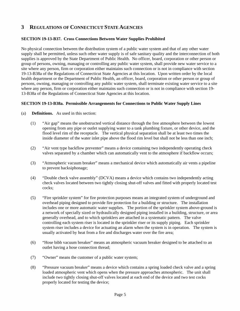
4.1.1 INTRODUCTION An air gap is required between all potable water lines and equipment or systems which may be subject to contamination. Exceptions are allowed by the RCSA to this requirement only if the appropriate approved device is substituted in place of the air gap. An air gap can be used for all toxic substances.
4.1.2 OPERATION An air gap is a physical unobstructed separation through free atmosphere between the free flowing discharge end of any pipe or outlet supplying potable water and the flood-level rim of a receiving receptacle. The air gap, when properly maintained and inspected, is the most reliable means of protection because it is not subject to mechanical failure. However, backflow prevention devices are substituted in place of an air gap in many cases because of operational problems such as loss of pressure or the introduction of contaminated air into the water supply.
4.1.3 INSTALLATION An approved air gap shall be installed with a minimum separating distance of at least two (2) times the inside diameter of the water supply pipe (measured vertically above the flood level rim of the receptacle). In no case, however, shall the separation be less than one (1) inch Careful attention must be paid in situations where a hose or extension piece can be attached to the potable water supply line. Fixtures equipped with an air gap must be re-inspected periodically to make sure that the air gap is not bypassed.
4.1.4 USES The use of the air gap for backflow prevention is governed by Section 19-13-B38a(b) of the RCSA. Unless devices are installed pursuant to Sections 19-13-B38a(c), (d), and (e) of the RCSA.
Page 12
Typical Uses
bathtubs; sinks; swimming pool fill inlets; fills for tank trucks and spraying equipment
Page 13
4.2 ATMOSPHERIC VACUUM BREAKER
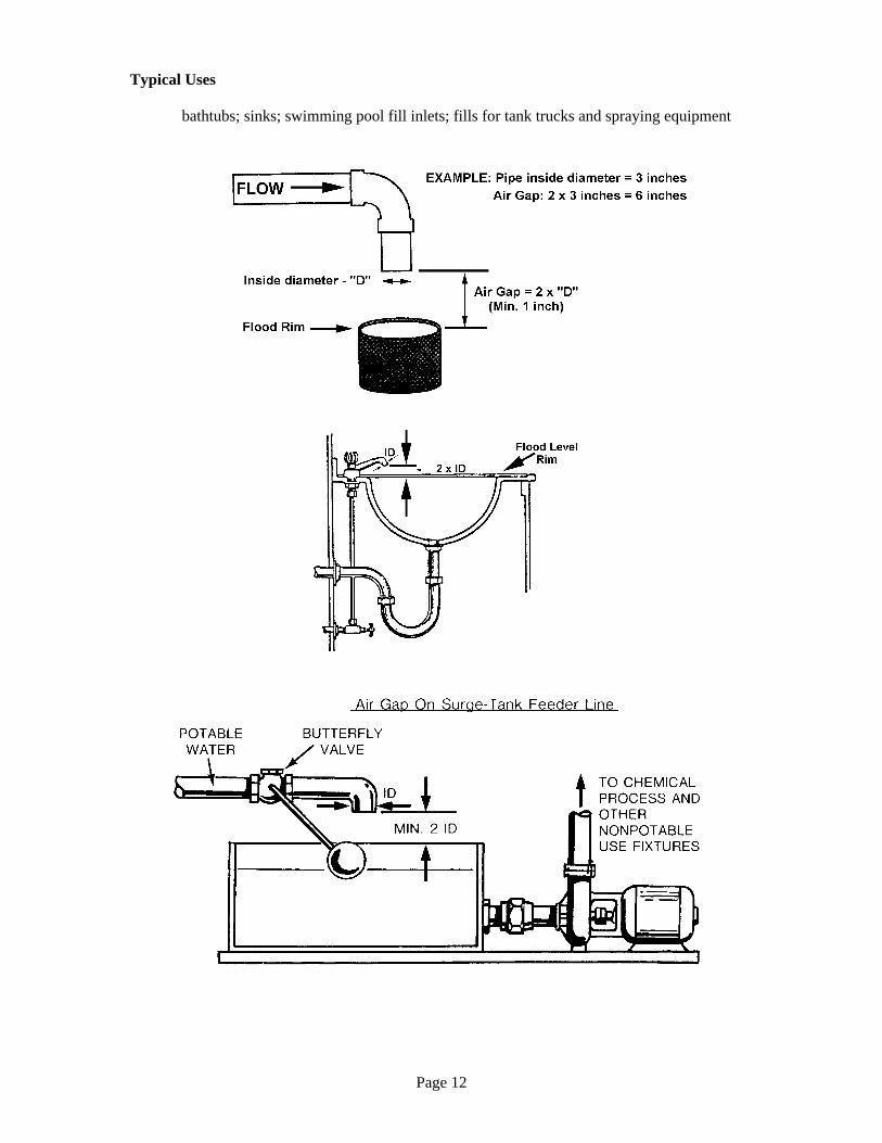
4.2.1 INTRODUCTION As stated in Sec. 19-13B38a(a), an atmospheric vacuum breaker is a mechanical device which automatically air vents a pipeline to prevent back-siphonage. It may be substituted for an air gap in instances such as irrigation or lawn sprinkler systems where chemicals are not added, flush valve toilets or inlets which are or may become submerged, or at marinas and docks on all hose bibbs other outlets to which a hose may be connected. It is important to be aware that this device protects against backsiphonage only.
4.2.2 A.S.S.E. AND/OR AWWA STANDARD A.S.S.E. Standard No. 1001 – Performance Requirements for Atmospheric Vacuum Breaker
4.2.3 OPERATION
During normal flow through this device incoming water lifts the poppet and simultaneously closes the atmospheric vent. If a negative pressure is created in the incoming line, the poppet drops, opening the atmospheric vent at the same time closing the water inlet. This prevents the creation of a vacuum in the discharge line downstream of the vacuum breaker and prevents back-siphonage.

Page 14
4.2.4 INSTALLATION The atmospheric vacuum breaker (A.V.B.) is effective against backflow caused by back-siphonage and should not be used if back-pressure can develop within the piping. The A.V.B. shall be installed so that it is not subject to back-pressure or continuous operating pressure of more than twelve (12) hours duration. There shall not be any means of shut-off downstream on the outlet side of the device. The A.V.B. shall be installed at least 6" higher than any outlet or height to which a hose or portable line could be raised. The A.V.B. shall not be installed in a location where toxic or objectionable fumes could enter and contaminate the potable water lines. The A.V.B. shall be installed in such a fashion that it will not be subject to corrosion which will render it inoperative.
4.2.5 USES The use of this device is governed by Section 19-13-B38a(e) of the RCSA.
Typical uses:
Flush valve toilets; hose bibb outlet to which a hose may be connected; dishwashers; photo developing machines; janitors slop sinks; beauty salon sinks and laboratory goose neck faucets.

Page 15
4.3 HOSE BIBB VACUUM BREAKERS
4.3.1 INTRODUCTION Permissible arrangements for connections to public water supply lines, allows the use of a hose bibb vacuum breaker designed to be attached to an outlet having a hose connection thread.
4.3.2 A.S.S.E. AND/OR AWWA STANDARD A.S.S.E. Standard No. 1011 – Performance Requirements for Hose Connection Vacuum Breakers.
4.3.3 OPERATION The HBVB consists of a check valve biased to a normally closed position and an atmospheric vent valve, which is loaded to a normally open position. When the device is pressurized, the check valve will open and the atmospheric vent will close allowing water to flow through the device. Under a backflow condition, the check valve will close and the vent will open allowing air into the system to prevent backsiphonage.
4.3.4 INSTALLATION This device can be installed without plumbing changes as it is screwed directly to the sill cock. They are available with a non removable feature to prevent unauthorized removal. When installed where freezing conditions exist it should have a draining feature. When installed on a hose with a spray nozzle attached the sudden opening and closing can cause a small discharge of water from the atmospheric ports.
4.3.5 USES The use of this device is governed by Section 19-13-B38a(e) of the RCSA.

Page 16
Typical Uses:
Janitors slop sink, marinas, wash down hoses, swimming pools, and all hose uses in general.
4.4 LABORATORY VACUUM BREAKERS
4.4.1 INTRODUCTION This device is specially designed for laboratory faucets where portable hoses can be attached. This device will prevent the back-siphonage of contaminated water back into the potable water supply.
4.4.2 A.S.S.E. AND/OR AWWA STANDARD A.S.S.E. Standard No. 1035 - Performance Requirements for Laboratory Vacuum Breakers.

Page 17
4.4.3 OPERATION Under pressure but with no demand on downstream equipment. Primary check seats against diaphragm, with diaphragm sealing off the atmospheric port. Secondary check seals against downstream seat . With flow through the valve. Primary check opens away from the diaphragm seal. The atmospheric ports remain closed by deflection of the diaphragm seal. Secondary check opens away from the downstream seat allowing water to flow through the valve. With a back-siphonage condition created. Secondary check seals tightly against downstream seat. Primary check seals tightly against diaphragm. Atmospheric port is now open permitting air to enter air break chamber. In the event of a fouled or leaking downstream check valve, leakage would be vented to atmosphere through the vent port.
4.4.4 INSTALLATION In most cases this device can be installed without plumbing changes. It is recommended that the device be secured to the faucet with loctite to prevent tampering.
4.4.5 USES The use of this device is governed by Section 19-13-B38a(e) of the RCSA.
Typical Uses: Laboratory gooseneck faucets, faucets installed outside laboratory ventilation hoods and all laboratory faucets where portable hoses attached.

Page 18
4.5 PRESSURE VACUUM BREAKER
4.5.1 INTRODUCTION The pressure vacuum breaker is designed for areas where back-siphonage could occur and there is a continuous operating pressure. It must not be installed in areas subject to back pressure.
4.5.2 A.S.S.E. AND/OR AWWA STANDARD A.S.S.E. Standard No. 1020 – Performance Requirements for Pressure Vacuum Breaker Backflow Assembly
4.5.3 OPERATION A device which contains a spring loaded check valve and a spring loaded atmospheric vent which opens when the pressure approaches atmospheric. The unit shall include two tightly closing shut-off valves located at each end of the device and two test cocks properly located for testing the device. As water flows through the device, it opens the first check valve and lifts the second which closes the air inlet. When water pressure drops to one (1) psi or below, the first check valve closes and the air inlet opens allowing air to enter the device and prevent a vacuum.

Page 19
4.5.4 INSTALLATION The device cannot be subject to back pressure but can be used under continuous pressure. It must be installed welve (12) inches above the highest outlet and must be tested annually. t
4.5.5 USES The use of this device is governed by Section 19-13-B38a(e) and (f) of the RCSA.
Typical Uses:
Lawn sprinkler systems (no chemicals), photo developers.
4.5.6 FIELD TESTING

Page 20
Test No. 1 Purpose To test the opening pressure differential of the air inlet valve. Requirement The air inlet valve shall open when the pressure in the body is 1.0 psi above atmospheric pressure. And, the air opening valve shall be fully open when the water drains from the body.
Steps:
a . Remove air opening canopy. b. Install the high-pressure hose of the differential pressure gage to test cock #2 and bleed air from the
hose and gage. c . Close shut-off valve #2; then close shut-off valve #1. d. Slowly open the high-pressure vent needle valve. Note and record the pressure differential at which
the air inlet valve opens. e . Close test cock #2 and remove equipment. f. Open shut-off valve #1.
Test No. 2 Purpose To test the check valve for tightness in the direction of flow. Requirement: The check valve shall be drip-tight in the normal direction of flow when the inlet pressure is 1 psi and the outlet pressure is atmospheric.
Steps:
a . Install a transparent tube approximately 27 3/4 inches long in test cock #1 and fill with water. b . Close shut-off valve #1. c. Open test cocks #1 and #2. Air inlet valve will open; and, if water remains at 27 3/4 inches in the
transparent tube the check valve is reported as "tight" or "OK". d . Close test cocks #1 and #2. Remove the transparent tube and open the shut-off valves #1 and #2. e. Replace air opening canopy.
Alternate method using a differential gage
Steps:
a . Attach high pressure hose of differential gage to the #1 test cock and vent all air from hose and gage. b . Close shut-off valve #1. c. Open test cocks #1 and #2. Air inlet valve will open; and the differential pressure indicated by the
gage will be the pressure drop across the check valve. This must be 1.0 psi or greater. Record this differential.
d . Close test cocks #1 and #2. Remove gage and open shut-off valves #1 and #2. e. Replace air opening canopy.

Page 21
4.5.6.1 TROUBLESHOOTING
Pressure Vacuum Breaker Trouble Shooting Guide
SYMPTOM CAUSE SOLUTION
a. Debris on sealing surface or guide surfaces
Disassemble and clean check valve surfaces
b . Damaged seat disc Disassemble and replace seal
1. Check valve fails to hold
1.0 PSID minimum
c. Weak or broken spring
Disassemble and replace spring
a. Debris restricting free operation
Disassemble and clean parts
b. Poppet seal adhering to bonnet
Disassemble and clean and/or replace defective parts
2. Poppet fails to open at 1.0
PSIG minimum
c. Weak spring load Replace bonnet assembly (1/2 – 1-1/4 ) Replace spring ( 1-1/2 & larger )
a. Damaged poppet seal Disassemble and replace seal
b. Cracked or damaged poppet
Disassemble and replace poppet seal
c. Cracked bonnet or damaged sealing edge
Disassemble and replace bonnet assembly
3. Minor leakage though air
vent
d. Debris on sealing surface
Disassemble and clean
a. Poppet not properly guided
Disassemble and replace defective parts
b. Major poppet or seal failure Disassemble and replace defective parts
c. Low down stream pressure Check pressure at No. 2 test cock; should e higher than 5 PSID if low system b
4. Significant discharge
through air vent
d. Insufficient inlet volume to operate device
Pressure needs to be increased or partially closed outlet gate valve to create higher pressure on poppet
5. Chatter during flow
conditions
a. Worn, damaged or
defective check valve guide
Disassemble and repair or replace guide

Page 22
4.6 SPILL-RESISTANT PRESSURE VACUUM BREAKER
4.6.1 INTRODUCTION The spill resistant vacuum breaker (SVB) is designed for areas were back-siphonage could occur. The SVB is ideally suited for indoor applications supplied with continuous pressure. It must not be installed in areas subject to back pressure.
4.6.2 A.S.S.E. AND/OR AWWA STANDARD A.S.S.E. Standard No. 1056 - Performance Requirements for Spill-Resistant Pressure Vacuum Breaker.
4.6.3 OPERATION The SVB includes an internally loaded check valve and a loaded air inlet valve opening to the atmosphere on the discharge side of the check valve between two resilient seated shutoff valves. The assembly includes one properly located resilient seated test cock, and one vent valve. The air inlet valve opens when the inlet pressure is 1 PSI or greater, and outlet pressure is atmospheric. The check valve is internally loaded and is designed to hold tight in the normal direction of flow with the inlet pressure at 1 PSI and the outlet under atmospheric pressure.
4.6.4 INSTALLATION 1. Install a minimum of 1" above flood level of fixture if factory deck mounted or not less than 6" if general
plumbing field application. 2 . Install bonnet side up and allow for accessibility for testing and servicing. 3. Do not install where back pressure could occur. Note: Do not install in concealed locations or areas where water leakage due to normal wear of the internal parts can cause water damage.

Page 23
4.6.5 USES
The use of this device is governed by Section 19-13-B38a (e) and (f) of the RCSA.
4.6.6 TEST PROCEDURE FOR SPILL RESISTANT VACUUM BREAKER
Test No.1 - Differential Test Requirement: Differential Pressure across check must be 1.0 psi or above Step 1. Remove air opening canopy. Step 2. Install hose between test cock and connection " A " high side of test kit. Step 3. Open test cock then bleed valve " A " on top of test kit. Bleed air from hose then close bleed valve "A"
on top of test kit. Step 4. Open needle valve "A" on high side of test kit. Step 5. Close shutoff valve No.2 then shut off valve No.1 on test assembly. Step 6. Slowly unscrew bleed screw on spill proof vacuum breaker body to relieve pressure down stream of
check (about 3 turns). Step 7. When dripping from bleed screw stops and psi needle on gauge stabilizes, record the differential
Pressure Test No.2 - Air Inlet -Vent Opening Requirement: Air inlet must start to open when supply pressure is 1.0 psi or above. Air inlet must be fully open when supply pressure is atmospheric. Step 8. Slowly open needle valve "C" bypass until psi gauge reads 1.0 psi then close needle valve "C" bypass
holding pressure at 1.0 psi. Step 9. Visually inspect that the vent on top is slightly open, about 1/32" to pass test. Step 10. Open needle valve "C" bypass fully until dripping from connection stops. Step 11. Visually inspect that the vent is fully open to pass test. Step 12. Replace air opening canopy on top of assembly. Step 13. Restore valve to original working order. Note: For both of the above test the kit must be held at the same level as the assembly being tested.

Page 24
4.7 INTERMEDIATE AIR VENT TYPE BACKFLOW PREVENTER
4.7.1 INTRODUCTION The air vent type back flow preventer, also referred to as a backflow preventer with intermediate vent, is used in low hazard areas and can be subject to continuous pressure.
4.7.2 A.S.S.E. AND/OR AWWA STANDARD A.S.S.E. Standard No. 1012 – Performance Requirements for Backflow Preventers with Intermediate Atmospheric Vent.
4.7.3 OPERATION The device consists of two independently operating check valves separated by a chamber which can vent to the atmosphere if backflow occurs.
Normal Flow – Checks Open – Vent Closed Negative Supply Pressure – Checks Closed – Vents Open
With flow through valve, primary check (1) opens away With a back-siphonage condition created, secondary From diaphragm seal (2). Atmospheric vent remains check (4) seals tightly against downstream seat (5). Primary Closed by deflection of diaphragm seal (2). Secondary check (1) seals tightly against diaphragm (2). Atmospheric Check (4) opens away from downstream seat (5) vent (3) is now open permitting air to enter air break Permitting flow of water through valve. Chamber. In the event of fouling of downstream check Valve, leakage would be vented to atmosphere through the Vent port thereby safeguarding the potable water from Contamination.

Page 25
4.7.4 INSTALLATION The device can be used for back-siphonage or back pressure and under continuous pressure. The vent must not be plugged or piped directly to a drain (unless an air gap is installed). It is only available up to ¾". It can be tested if installed with valves and test cocks although this is not commonly done and testing is not required.
4.7.5 USES The use of this device is governed by Section 19-13-B38a(c) (3) of the RCSA.
Typical Uses:
Boiler with no treatment. Heat exchanger with no treatment. Carbonator (special device see illustration).
4.8 AIR VENT TYPE BACKFLOW PREVENTER FOR BEVERAGE MACHINE CARBONATORS
4.8.1 INTRODUCTION
The air vent backflow preventer for beverage machines are used to prevent backflow of carbon dioxide gas and carbonated water in to the water supply to vending machines, thus eliminating the hazardous reaction of carbon dioxide with copper tubing.
4.8.2 A.S.S.E. AND/OR AWWA STANDARD A.S.S.E. Standard No. 1022 – Performance Requirements for Air Vent Type Backflow Device.

Page 26
4.8.3 OPERATION This backflow prevention device consists of two independently acting check valves biased to a normally closed position. An atmospheric port is located between the check valves and is biased to a normally open position. The dual check with atmospheric vent will discharge liquids, gases, or both if there is a failure of the downstream check and the backpressure exceeds the supply pressure.
4.8.4 INSTALLATION
The device must be installed downstream from copper pipes and immediately downstream from a removable in-line mesh screen located in the water pump inlet.
4.8.5 USES
The use of this device is governed by Section 19-13-B38a(c) (3) of the RCSA.

Page 27
4.9 DOUBLE CHECK VALVE ASSEMBLY
4.9.1 INTRODUCTION The double check valve assembly (DCVA) is approved only for use on fire sprinkler systems with siamese connections. The Double Check Valve Assembly consists of two internally spring loaded check valves, two resilient seated shutoff valves, and four properly located resilient seated test cocks. This assembly shall be installed as a unit as furnished by the manufacturer. This assembly is effective against backflow caused by back pressure and back-siphonage.
4.9.2 A.S.S.E. AND/OR AWWA STANDARD A.S.S.E. Standard No. 1015 – Performance Requirements for Double Check Backflow Prevention Assembly. AWWA CC510 – AWWA Standard for Double Check Valve Backflow-Prevention Assembly.
4.9.3 OPERATION The Double Check Valve Assembly consists of two internally spring loaded check valves, two resilient seated shutoff valves, and four properly located resilient seated test cocks. This assembly shall be installed as a unit as furnished by the manufacturer. This assembly is effective against backflow caused by back pressure and back siphonage.

Page 28
4.9.4 INSTALLATION It is critical that all DCVAs be installed with adequate space consideration for testing, repair, and maintenance. All assemblies require a minimum clearance for removal of pins and/or check assemblies. Again, consult the specific manufacturer's installation instructions prior to installation. IN ALL CASES, CONSULT WITH THE RESPONSIBLE LOCAL WATER PURVEYOR FOR THEIR SPECIFIC SPACE AND INSTALLATION REQUIREMENTS. All DCVAs shall be tested after installation and repairs to insure their proper installation and satisfactory operation. In all vault installations, consult the responsible local water purveyor for their specific requirements. The vault shall be large enough for free access for workers to enter for testing and/or repairing the assembly. This includes adequate clearance all around the assembly for maintenance. Include an adequate hatch in the cover, or complete cover removal through which personnel may access the vault. Provisions must be made for crane access for removing and installing larger assemblies. Large vaults must also be provided with ladders. Check the specific manufacturer's recommendations. IN ALL CASES, WHENEVER ACCESS TO A VAULT IS REQUIRED, FOLLOW AND COMPLY WITH STATE AND LOCAL SAFETY REQUIREMENTS REGARDING CONFINED SPACE ENTRY. Be careful to insure that the assembly is not installed where the temperature and pressure is maintained above the assembly's rated and labeled capacities. Thermal water expansion and/or water hammer downstream of the assembly can cause excessive pressure. To avoid possible damage to the system and assembly from this situation, use water hammer arresters or surge protectors. Have the assembly sized hydraulically to avoid excessive pressure loss. The head loss is not necessarily proportional to flow. Some assemblies have a high head loss at low flows and low head loss at high flows. The water purveyor is not responsible for sizing backflow prevention devices. In areas where debris content in the water supply is high, good plumbing practice recommends a strainer with blowout tapping ahead of the assembly. THOROUGHLY FLUSH THE LINES BEFORE INSTALLING THE ASSEMBLY. Years of experience have shown that most "failure to test satisfactory" results in new installations are caused by debris fouling one of the check valves or the relief valves.
4.9.5 USES The use of this device is governed by Section 19-13-B38a(d) of the RCSA. It may also be used where no devices are required by the RCSA.
4.9.6 FIELD TESTING The following field testing procedure is currently being taught by NEWWA instructors. It is based upon a proven method of testing that obtains a fast and accurate assessment of the performance of the device based upon nationally accepted performance criteria. At the same time it accomplishes the testing with a minimum of complication, and in a logical work saving sequence. This test procedure is recommended, and will work for virtually all current production differential pressure test kits. Also, it is assumed that prior to initiating a test, the following preliminary testing procedures will have been followed:

Page 29
1. The type of device to be tested has been correctly determined. 2. The direction of flow has been obtained. 3. The test cocks have been numbered 4. Test adapters have been assembled and "blown out". 5. Permission to shut down the water supply has been obtained.
We will be checking the double check valve assembly for the following performance characteristics:
1. The first check valve is tight, and has a minimum pressure differential across it of 1 psid. 2. The second check valve is tight and has a minimum pressure differential across it of 1 psid.
4.9.6.1 TEST PROCEDURE Some field testing procedures for testing double check valve assemblies require that the number 1 shut-off valve be closed to accomplish the test. This procedure may introduce debris such as rust and tuberculin into the valve that will impact against check valve number 1 or number 2 and compromise the sealing quality. This potential problem should be considered prior to the selection of the appropriate test method. The test method requiring closing the number 2 shut-off is detailed in the USEPA Cross Connection Control Manual on page 29. The NEWWA test method which does not require closing the number 1 shut-off is detailed as follows: NEWWA Test Method Utilizing the differential pressure gauge and not shutting off number 1 shut-off valve. (Figure 41). Step 1: Checking check valve number 1
1. Verify that the number 1 shut-off is open. Shut-off number 2 shut-off valve. 2. Connect the high hose to test cock number 2. 3. Connect the low hose to test cock number 3. 4. Open test cocks 2 and 3. 5. Open high side bleed needle valve on test kit bleeding the air from the high hose. Close the high side
bleed needle valve. 6. Open low side bleed needle valve on test kit bleeding air from the low hose. Close the low side bleed
needle valve. 7. Record the differential gauge pressure reading. It should be a minimum of 1 psid. 8. Disconnect the hoses.

Page 30
Step 2: Checking check valve number 2
1. Connect the high hose to test cock number 3. 2. Connect the low hose to test cock number 4. 3. Open test cocks number 3 and 4. 4. Open high side bleed needle valve on the test kit bleeding the air from the high hose. Close the high
side bleed needle valve. 5. Open high side bleed needle valve on test kit bleeding the air from the
high hose. Close the high side bleed needle valve. 6. Record the differential gauge pressure reading. It should be a minimum of 1 psid. 7. Disconnect the hoses.
To check tightness of number 2 shut-off valve, both the check valves must be tight and holding a minimum of 1 psid. Also, little or no fluctuation of inlet supply pressure can be tolerated.
The testing is performed as follows:
1. Connect the high hose to number 2 test cock. 2. Connect the low hose to number 3 test cock. 3. Connect the by-pass hose to number 4 test cock. 4. Open test cocks number 2, 3 and 4. 5. Open high side bleed needle valve on the test kit bleeding air from the high hose. Close the high side
bleed needle valve. 6. Open low side bleed needle valve on test kit bleeding air from the low hose. Close the low side bleed
needle valve. 7. The differential gauge pressure should read a minimum of 1 psid. 8. Open the high side control needle valve and the by-pass hose control needle valve on the test kit (This
supplies high pressure water downstream of check valve number 2). 9. Close test cock number 2. (This stops the supply of any high pressure water downstream of number 2
check valve). If the differential pressure gauge holds steady, the number 2 shut-off valve is recorded as being tight. If the differential pressure gauge drops to zero, the number 2 shut-off valve is recorded as leaking.
With a leaking number 2 shut-off valve, the device is, in most cases, in a flow condition, and the previous test readings taken are invalid. Unless a non-flow condition can be achieved, either through the operation of an additional shut-off downstream, or the use of a temporary compensating by-pass hose, accurate test results will not be achieved. This completes the standard field test for a double check valve assembly. Prior to removal of the test equipment, the tester should insure that he opens number 2 shut-off valve thereby reestablishing flow. All test dates should be recorded on appropriate forms and the test kit drained of water It should be noted that this test procedure checks the tightness of both the first and second check valves in-the direction of flow. It does not back pressure test either check valves. Extensive field testing has proven, without a doubt, that a fouled first or second check valve, in a double check valve assembly, can seal tightly against backpressure and appear as satisfactory to the tester. These same fouled checks will fall a tightness check when tested in the direction of the flow. The backpressure test will, in many cases, cause the disc rubber to seat around the foul. Testing for tightness and the minimum differential pressure of 1 psid in the direction of flow is a true indication of the tightness of the check assemblies. It also insures correct alignment of the faces of the disc rubber and seat.
Page 31
As stated in the preliminary introduction to the detailed test procedure, this test procedure does not require the closure of the upstream gate valve by so doing, we do not introduce debris into the check valve assemblies.
4.9.6.2 TROUBLESHOOTING
Double Check Valve Assembly Trouble Shooting Guide SYMPTOM CAUSE SOLUTION
a. Shut off valve not closed completely
a. Close # 2 shut off valve or inspect for possible though leakage
b. Check valve fouled with debris
b. Inspect and clean seat disc and seat
Check valve fails to hold 1 PSID
c. Check poppet stem not moving freely in guide
c. Inspect for debris or deposits on poppet stem or guide
4.10 REDUCED PRESSURE PRINCIPLE BACKFLOW PREVENTERS
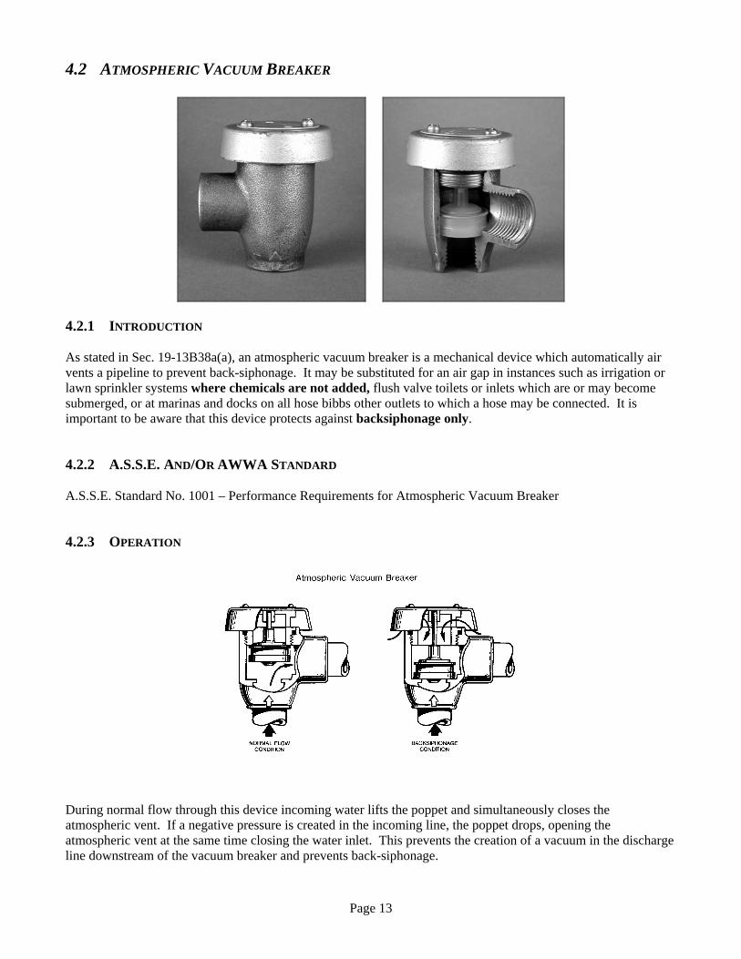
4.10.1 INTRODUCTION Also called RPD or RPZ (zone). These devices are the best mechanical protection made and are used for high hazard applications. Reduced pressure devices consist of two independently operating spring loaded check valves with a relief port assembly between the two checks, adding up to three securities. If both checks fail the relief port would be the third protection against backflow. The high reliance factor simply derives from the fact that as these devices are tested once every year it is highly unlikely that all three securities will fail within that time period.
4.10.2 A.S.S.E. AND/OR AWWA STANDARD A.S.S.E. Standard No. 1013 – Performance Requirements for Reduced Pressure Principle Backflow Preventers. AWWA C511 – AWWA Standard for Reduced-Pressure Principle Backflow-Prevention Assembly.

Page 32
4.10.3 OPERATION RPDs work under the principle, that water passing through a sequence of two spring loaded check valves, has less or reduced pressure after passing through the first check valve, compared to the supply pressure before the check. A minimum of 5 pounds for the spring -load of the first check is required, while the second check usually has only 1 pound. That means that if the supply pressure were 60 PSI, the water in the reduced pressure zone would have at least 5 PSI less pressure and after passing through the second check an additional 1 PSI less pressure. So, based on the fact that the pressure between the two checks is reduced or less than the incoming supply pressure, the relief port is held shut by routing the supply (full) pressure against a diaphragm that works against the spring load of the relief port. The spring load on the relief port must be no less than 2 pounds, so that when the supply pressure drops to less than 2 pounds difference (between supply side and reduced pressure zone) the relief port will open and drain the water out of the reduced pressure zone. Although there are many different manufacturers with sometimes odd looking devices, they all work under the same principle. On the following pages there are some examples with cross-sections of Reduced Pressure Principle Devices that will illustrate the working principle.
4.10.4 INSTALLATION OF RP DEVICES
1. All RPD's should be installed in an easily accessible area to facilitate maintenance and testing. Have plumbers contact you prior to installation to verify the location of the device. (Check manufacturers recommendation for minimum clearance, etc.)
2. Do not install an RPD in a structure below ground level unless approved provisions are made to keep the
pit dry. If a device is installed in a deep chamber, the chamber should be well ventilated, drained by gravity and have a removable top to facilitate access to the device. IN ALL CASES, CONSULT WITH THE RESPONSIBLE LOCAL WATER PURVEYOR FOR THEIR SPECIFIC SPACE AND INSTALLATION REQUIREMENTS.
3. Bypassing an RPD during testing or repair is prohibited. Installation of another RPD in parallel is
required if continuous supply is required.
4. RPD's should be located in an area where water spillage is not objectionable. A drain, capable of handling the maximum flow from the relief port should be provided but is not mandatory. However, when installing a drain for the relief valve an air gap must be provided between the drain and the relief port. All devices must be protected against freezing, flooding, and mechanical damage.
5. When installing an RPD on the feed line to a pressure vessel, always install the pressure relief between
the RPD and the pressure vessel. On fire sprinkler systems, always install the RPD (before) upstream of the siamese connection.
6. It is recommended to install a strainer before the device to prevent unnecessary maintenance.
7. Owners shall label all piping to the satisfaction of the inspector. Upstream of the RPD shall be labeled
potable and downstream of the RPD shall be labeled non-potable, other than when a device is installed to contain a building’s plumbing system.
4.10.5 USES The use of this device is governed by Section 19-13-B38a(c) of the RCSA. Reduced Pressure Devices are used for protection in high hazard applications as found in plating shops, sewer plants, hospitals and chemical plants, treated boiler systems, etc., just to mention a few.

Page 33
4.10.6 MAINTENANCE Most RPD failures are due to dirt and debris. Many times, if a customer needs to call in an outside plumber to do the repair job, the plumber will recommend a new device because he does not know how to repair an RPD. That is why it is important that the inspector has a basic idea of how easy a failing device can be repaired by cleaning the checks and have that done before calling on outside help or the manufacturer. Although the inspector is not obliged to give any advice on repairs, it can be very helpful and lead to an excellent business relationship. However, should it be necessary to remove the device for repair, make sure that the owner does not install a spool piece and leave the line unprotected. Remember to check the atmosphere if the device is installed in a deep chamber and provide a jumper wire to bypass stray electric currents, if the device is to be removed. All confined space entry regulations (OSHA) shall be followed. Valve springs on large devices are strong and should be removed with caution. On many RPD's the parts in #1 check valve are not necessarily interchangeable with the parts in check valve#2. If an RPD is continuously draining either check or the relief port has failed. If the water starts dripping from an RPD after the #2 shutoff valve has been closed, the #1 check valve is probably leaking. When both shutoff valves are closed and test cock #2 is opened, water should begin to discharge from the relief port.
4.10.7 MAINTENANCE OF LARGE RP-DEVICES With larger devices you may run into the problem, that when the checks have been cleaned out and the water is turned back on, the #1 check is still or again leaking. This is often due to the fact that for repairs the #1 gate valve has to be shut as well as the #2 gate valve. Most of these valves are old and have dirt in them. Now, after repairs have been made and the #1 gate valve is opened, the shearing effect of releasing the water through the valve loosens new debris that will immediately foul the first check again. The best way to avoid this is to open and close the #1 gate valve several times before the repairs are started. Then, once the checks have been cleaned out, it may also be necessary to slowly charge the RPD with water through a hose connection between test cock #1 and test cock #2. Then, when gate valve #1 is opened the water will not gush into the RPD and subsequently will not loosen any additional debris off the valve.

Page 34
Reduced-Pressure-Principle Device – Reverse Flow
Reduced-Pressure-Principle Device – Reverse Flow

Page 35
4.10.8 FIELD TESTING The following field testing procedure is currently being taught by NEWWA instructors. It is based upon a proven method of testing that obtains an accurate assessment of the performance of the device based upon nationally accepted performance criteria, and at the same time accomplishes the testing with a minimum of complication, and in a logical work saving sequence. This test procedure is recommended, and will work for, virtually all current production differential pressure test kits. Also, it is assumed that prior to initiating a test, the following preliminary testing procedures will have been followed:
1 . The type of device to be tested has been correctly determined. 2 . The direction of flow has been obtained. 3 . The test cocks have been numbered. 4 . Test adapters have been assembled and "blown out". 5 . Permission to shut down the water supply has been obtained. 6 . The downstream shut-off valves have been shut off. 7. No water has emitted from the relief valve discharge.
We will be checking the reduced pressure principle device for the following four performance characteristics:
1 . The first check valve is tight, and has a minimum pressure differential across it of 5 psid. 2 . The second check valve is tight. 3 . The downstream shut-off is tight and not leaking. 4. The relief valve opens at a minimum pressure of 2 psi below the inlet supply pressure.
4.10.8.1 TEST PROCEDURE Field testing of a reduced pressure principle backflow preventer is accomplished utilizing a differential pressure gauge. Step 1
Test to insure that the first check valve is tight and maintains a minimum pressure differential across it of 5 psi. (Figure 39).
1. Verify that number 1 shut-off valve is open. Close number 2 shut-off valve. If there is no drainage
from the relief valve, it is assumed that the first check is tight 2. Close high side and low side test kit valves. Leave by-pass, or drain hose test kit valve open. 3. Connect the high pressure hose to test cock number 2. 4. Connect the low pressure hose to test cock number 3. 5. Open test cocks number 2 and number 3. 6. Open high-side bleed needle valve on test kit bleeding the air from the high hose. Close the high side
bleed needle valve. 7. Open the low side bleed needle valve on test kit bleeding air from the low hose. Close the low side
bleed needle valve. Record the differential gauge pressure. It should be a minimum of 5 psid.

Page 36
Step 2
Test to insure that the second check is tight against backpressure. (Figure 40). 1. Leaving the hoses hooked up as in the conclusion of Step 1 above, connect the bypass hose to test
cock number 4. 2. Open test cock number 4, the high control needle valve and the bypass hose control needle valve on
the test kit. (This supplies high pressure water downstream of check valve number 2.) If the differential pressure gauge falls off and water comes out of the relief valve, the second check is recorded as leaking. If the differential pressure gauge remains steady, and no water comes out of the relief valve, the second check valve is considered tight.
Step 3
To check the tightness of number 2 shut-off valve, leave the hoses hooked up the same as at the conclusion of Step 2 above, and then close test cock number 2. This stops the supply of any high pressure water downstream of check valve number 2. If the differential pressure gauge reading holds steady, the number 2 shut-off valve is recorded as being tight. If the differential pressure gauge drops to zero, the number 2 shut-off valve is recorded as leaking. With a leaking number 2 shut-off valve, the device is, in most cases, in a flow condition and the previous readings taken are invalid. Unless a non-flow condition can be achieved, either through the operation of an additional shut-off downstream, or the use of a compensating temporary by-pass hose, (Ref: Fig. 40), accurate test results will not be achieved.

Page 37
Step 4
To check that the relief valve opens at a minimum pressure of 2 psi below inlet pressure.
With the hoses hooked up the same as at the conclusion of Step #2, open test cock number 2 and then slowly open up the low control needle valve on the test kit and record the differential pressure gauge reading at the point when the water initially starts to drip from the relief valve opening. This pressure reading should not be below 2 psid.
This completes the standard field test for a reduced pressure principle backflow preventer. Before removal of the test equipment, the tester should insure that he opens number 2 shut-off valve thereby reestablishing flow. Also, the test kit should be thoroughly drained of all water to prevent freezing by opening all control needle valves and bleed needle valves.
All test data should be recorded on appropriate forms.
Note: The steps outlined above may vary in sequence depending upon local regulations and/or preferences.
It should be noted that in this test procedure, the performance check of the second check valve consists of a backpressure test. If the second check valve is fouled, the downstream shut-off tight, and the relief valve operating properly, water will exit from the relief valve and the differential pressure gauge will drop simultaneously. This constitutes ample indication that the second check valve is fouled and is a true representation of actual field conditions with a fouled second check in a reduced pressure principle device.
4.10.8.2 TROUBLESHOOTING While it is not the utility cross connection inspector's responsibility to diagnose or repair problems with cross connection devices, it may be useful to understand the possible source of a problem in a failed device. The following tables list some problems and possible causes for failure in RPD’s and Pressure Vacuum Breakers.
REDUCED PRESSURE PRINCIPLE BACKFLOW PREVENTER TROUBLESHOOTING GUIDE
PROBLEM POSSIBLE CAUSE Relief valve discharges continuously. 1. Faulty 1st check.
2. Faulty 2nd check with back-pressure condition. 3. Faulty relief valve. Relieve valve discharges after No. 2 shut-off valve is closed.
1. Faulty first check a. dirty of damaged disc b. dirty or damaged seat
Pressure drop across 1st check less than 5 psi.
1. Faulty spring.
Relief valve discharges. 1. Line pressure fluctuation occurs intermittently.
2. Device working property, back-siphonage condition exists. 3. Water hammer.
Leaky 2nd Check. 1. Dirty or damaged disc. 2. Dirty or damaged seat.
Relief valve does not open, Differential drops to zero.
1. Relief valve stuck shut from corrosion or scale. 2. Relief valve sensing line(s) plugged, not functioning.
Relief valve does not open, differential on gage does not drop.
1. Leaky No. 2 Shut-Off Valve is allowing flow through device.

Page 38
4.11 TRAP PRIMER
4.11.1 INTRODUCTION A trap primer shall be installed in plumbing systems to prevent floor drain traps from losing their water seal by evaporation. Maintaining the water seal will prevent the backflow of sewer gas into the buildings or rooms where the traps are installed.
4.11.2 A.S.S.E. AND/OR AWWA STANDARD A.S.S.E. Standard No. 1018 – Performance Requirements for Trap Primer.
4.11.3 OPERATION Water flow acting against the main reaction disc (1), which forces the reaction disc in the upward position and removes the trap disc (2) from the plastic trap seat (3). A spurt of water is then delivered to the trap. However, with increased flow, the main reaction disc (1) continues to lift and seals off the closing disc (4) to stop the flow to the trap. When the flow through valve is stopped, the trap disc (2) is returned to the closed position, and in the process, delivers a spurt of water to the trap before closing off.
4.11.4 INSTALLATION The device must be installed so it is accessible for inspection and repair and must be at least 6" above the grid of the floor drain of the flood rim of the equipment which the primer serves.
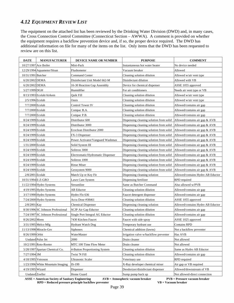
Page 39
4.12 EQUIPMENT REVIEW LIST The equipment on the attached list has been reviewed by the Drinking Water Division (DWD) and, in many cases, the Cross Connection Control Committee (Connecticut Section – AWWA). A comment is provided on whether the equipment requires a backflow prevention device and, if so, the proper device required. The DWD has additional information on file for many of the items on the list. Only items that the DWD has been requested to review are on this list.
DATE MANUFACTURER DEVICE NAME OR NUMBER PURPOSE COMMENT 10/27/1997 Ace Boiler Mini-Pack Instantaneous hot water heater No device needed 12/29/1994 Aquameter/Sloan Flushometer Vacuum breaker Allowed 10/31/1991 Butcher Command Center Cleaning solution dilution Allowed w/air vent type 6/20/2002 DEMA Disinfectant Unit Model 662-M Disinfectant dilution Allowed with VB 6/20/2002 DEMA 16-30 Reaction Gap Assembly Device for chemical dispenser ASSE 1055 approved 5/27/1999 DGH Humidifier For air conditioners Needs air vent type or VB 8/13/1993 Ecolab/Airkem Quik Fill Cleaning solution dilution Allowed w/air vent type
2/5/1996 Ecolab Oasis Cleaning solution dilution Allowed w/air vent type 7/7/2000 Ecolab Control Tower IV Cleaning solution dilution Allowed/contains air gap 7/7/2000 Ecolab Compac B.A. Cleaning solution dilution Allowed/contains air gap 7/7/2000 Ecolab Compac P.B. Cleaning solution dilution Allowed/contains air gap
8/24/1999 Ecolab Distributor 600 Dispensing cleaning solution from solid Allowed/contains air gap & AVB 8/24/1999 Ecolab Distributor 3000 Dispensing cleaning solution from solid Allowed/contains air gap & AVB 8/24/1999 Ecolab Ecoclean Distributor 2000 Dispensing cleaning solution from solid Allowed/contains air gap & AVB 8/24/1999 Ecolab FX-3 Dispenser Dispensing cleaning solution from solid Allowed/contains air gap & AVB 8/24/1999 Ecolab Power Activator/Vanguard Washmax Dispensing cleaning solution from solid Allowed/contains air gap & AVB 1/31/2000 Ecolab Solid System III Dispensing cleaning solution from solid Allowed/contains air gap & AVB 8/24/1999 Ecolab Solitron 3000 Dispensing cleaning solution from solid Allowed/contains air gap & AVB 8/24/1999 Ecolab Electromatic/Hydromatic Dispenser Dispensing cleaning solution from solid Allowed/contains air gap & AVB 8/24/1999 Ecolab Solitron 1000 Dispensing cleaning solution from solid Allowed/contains air gap & AVB 8/24/1999 Ecolab Rinse Miser Dispensing cleaning solution from solid Allowed/contains air gap & AVB 8/24/1999 Ecolab Geosystem 9000 Dispensing cleaning solution from solid Allowed/contains air gap & AVB
2/8/2001 Ecolab Match Up or Key Fit Dispensing cleaning solution Allowed/contains Hydro AB Eductor 10/31/1994 E-Z-GRO Lawn Care System Dispensing fertilizer RPD required 11/22/1994 Hydro Systems Streamline Same as Butcher Command Also allowed w/PVB 4/19/1995 Hydro Systems AB Eductor Cleaning solution dilution Allowed/contains air gap 3/17/1990 Hydro Systems Hydro Flo 636 Faucet detergent dispenser Allowed/contains air gap 7/24/2000 Hydro Systems Accu Dose #38461 Cleaning solution dilution ASSE 1055 approved
2/8/2001 Kay Chemical Dispenser Dispensing cleaning solution Allowed/contains Hydro AB Eductor 8/30/1996 SC Johnson Professional SCJP Air Gap Eductor Cleaning solution dilution Allowed/contains air gap 7/24/1997 SC Johnson Professional Single Port Integral AG Eductor Cleaning solution dilution Allowed/contains air gap 8/26/2002 Moen 7430 Kitchen Faucet Faucet with side spray ASSE 1025 approved 3/31/1995 Melco Mfg Hydrant Watch Dog Temporary hydrant use Contains RPD
11/13/1998 Miracle-Gro Siphonex Chemical addition (lawns) Not a backflow preventer 8/26/1999 Orbit WaterMaster Irrigation valve w/backflow preventer Has AVB
Undated Pulse Jet 2000 Drain cleaner Not allowed 10/2/1991 Roto-Rooter MTC 100 Time Flow Meter Drain cleaner Not allowed 5/28/1997 Spartan Chemical Co. 4-Button Proportioning System Cleaning solution dilution Same as Hydro AB Eductor 7/27/1994 3M Twist 'N Fill Cleaning solution dilution Allowed/contains air gap 4/18/1995 Vetroson Ultrasonic Scaler Veterinary use RPD required 1/23/1996 White Mountain Imaging IS-199 X-Ray developer chemical mixer Air gap or VB required 4/19/1995 Wizard Dispenser Deodorizer/disinfectant dispenser Allowed/downstream of VB
Undated Zoeller Home Guard Sump pump back up Not allowed-direct connection ASSE = American Society of Sanitary Engineering AVB = Atmospheric vacuum breaker PVB = Pressure vacuum breaker
RPD = Reduced pressure principle backflow preventer VB = Vacuum breaker

Page 40
5 TESTING PROGRAM Annual testing of RPD's, DCVA's and pressure vacuum breakers (PVB's) is necessary to assure that they continue to operate properly and serve the purpose for which they were installed. The interval between tests should not exceed one (1) year. New devices should be inspected and tested shortly after installation to assure that they have been installed properly and debris resulting from the installation has not interfered with the function of the device. At the time of testing you should always check that the device has not been bypassed. The maintenance of backflow preventers and the responsibility of keeping them in good working order lies with the owners of the device. The customer should be notified of the annual test. Depending on your setup this can he done either by letter or by telephone. After the test of a device you should fill out the test form and give a copy of it to the customer. If a device fails the test, a time limit for the repair should be noted on the form. A record of all RPD's, DCVA's, and PVB's must be kept on a history card or on computer file. All tests and failures must be noted. It is recommended that devices be tagged after they are tested for easy identification and as a test reminder.
Example of a Device Tag
5.1 BACKFLOW CERTIFICATION CATEGORIES 1. Certified Backflow Preventer Testers
Section 19-13-B38a(e)(7) of the RCSA requires that public water systems with testable backflow preventers, have the devices tested by a person who has completed and passed a course on testing of backflow preventers, administered or approved by the Department of Public Health. Although some systems will accept test results from non-system personnel, testing is the responsibility of the utility. Prior to testing devices, the tester should verify if the appropriate system will accept the test results. GENERAL TESTER - A person employed by a water utility to perform the required testing on all devices. LIMITED TESTER - An employee of a utility's consumer who has been delegated the duty of testing and maintaining the device(s) located only within a specific company.
Page 41
MANUFACTURER'S AGENT - A person who is employed by or a distributor for a manufacturer of backflow-equipment. He is restricted to testing and maintaining only the line(s) of products he represents. Test results cannot be used to fulfill annual testing requirements. PRIVATE TESTER -A person hired by a consumer or a water utility to perform the required testing.
2. Certified Cross Connection Survey Inspectors
Section 19-13-B102(f)(3) of the RCSA requires that public water systems with certain types of premises have these premises inspected for cross connection by a person who has completed and passed a course on cross connection inspections administered or approved by the Department of Public Health. Although some utilities may contract with private companies to perform this work, surveying is the responsibility of the utility. Certification does not guarantee that survey reports will be accepted by all water utilities. GENERAL INSPECTOR - A person employed by a water utility to perform the required cross connection surveys. PRIVATE INSPECTOR - A person hired by a water utility to perform the required cross connection surveys. NOTE: All tests and inspections must be done by certified personnel. The utility should spot check 5% of the tests or surveys done by the tester/inspector.
5.2 DIFFERENTIAL PRESSURE GAUGE
The differential pressure gauge is the main working part of the backflow preventer test kit. With this gauge, the tester can see if there are fouled check valves, test relief valve openings and accurately test for differential pressure zones. This gauge enables the tester to visually locate problems that otherwise would be impossible. The differential pressure gauge is a precision instrument designed to perform under conditions of shock, vibration and overpressure. There will be times when this gauge will require inspection and testing by a company that is equipped to calibrate this instrument to the following criteria recommended by the Cross Connection Control Committee and the Connecticut Department of Public Health.
A. The differential pressure gauge should be tested for accuracy and recalibrated if necessary every 100 tests or one year, whichever occurs first.
B. The testing and recalibration must be performed by a reputable company that is equipped to do such work.
C. Retain receipt of payment as proof that the gauge was tested and calibrated and enter this notice when gauge was tested on the cross connection form to the Connecticut Department of Public Health.
D. No unauthorized personnel should attempt to calibrate or tamper in any manner with the differential pressure gauge.
E. The differential pressure gauge must be tested and recalibrated to be accurate to within 1/4 of a pound.

Page 42
5.3 RECORD KEEPING It shall be the duty of the cross connection control inspector to keep, maintain and update any and all records, reports or correspondence that may be related to cross connection control. The file on all inspections or any related inspection, copies of all correspondence and a copy of the inspection report should be kept and telephone conversations should be documented. Any important phone call should be followed by a letter confirming the conversation. Records and schedules should be kept and maintained in reference to annual testing of reduced pressure devices, pressure vacuum breakers and double check valves. The amount of necessary correspondence is up to the judgment of the inspector and his capability of writing letters or have someone type his letters. One suggestion is the two part inspection form where the customer receives a copy at the end of the inspection and no further correspondence is necessary. With small businesses a telephone call to make an appointment for testing or an inspection may be sufficient while with larger companies a written notice may be more appropriate. However, if problems occur, they should always be documented in a letter. There are a variety of ready made computer software programs for backflow prevention record keeping on the market but any good database program can easily be tailored to your needs and may even be better. The annual Cross Connection Survey Report, which must include all inspections and tests done during that year, is due on the 1st of March of the following year. Therefore it should be started as soon as possible and constantly updated, to avoid unnecessary pressure and delay at the time it is due. On the following pages are sample letters, reports forms, etc., which may give you some guidelines.

Page 43
5.3.1 CROSS CONNECTION SAMPLE INSPECTION FORM
Our Cross Connection Inspector visited your premise today to check for compliance to Sections 19-13-B37, 19-13-B38, 19-13-B39, 19-13-B45, and 19-13-B102 of the Regulations of Connecticut State Agencies (RCSA). You are expected to make these corrections as soon as possible but no later than the reinspection date.

Page 44
5.3.2 CROSS CONNECTION ANNUAL TEST SAMPLE REPORT

Page 45
5.3.3 CROSS CONNECTION SURVEY REPORT FORM INSTRUCTIONS 1. This report is due annually by March 1 for the preceding calendar year pursuant to Section 19-13-B102(f)
of the Regulations of Connecticut State Agencies. 2. Fill in the water system name, survey year and page number on each page.
Inspection Summary pages – Annual and Five Year 3. In the “Categories of Concern” column write one or more of the following codes for any of these items that
exist on the property:
(1) Any water supply source other than that of the public water system is known to exist. (2) Toxic or objectionable chemical or biological substances are used in water solution on public,
commercial or industrial premises. (3) Water pressure is raised by pumping on other than residential premises above that furnished by the
supplier. (4) There is a water storage tank, public swimming pool or water filter, for other than residential use. (5) There is known to be a sprinkler system for either fire protection or irrigation.
4. Under “Violations” in the “Status” column, enter one or more of the following codes:
(1) Correction has been scheduled (include the completion date on the Comments page). (2) Referred to local director of health for enforcement (3) Referred to State Department of Public Health for enforcement (4) Service terminated (5) Violation letter issued (6) Other (provide specific information on Comments page)
5. Under “Testable Backflow Preventers”, only list devices that are required to be tested pursuant to Section
19-13-B38a of the Regulations of Connecticut State Agencies.
6. Under “Testable Backflow Preventers”, report numbers for all ANNUAL tests performed during the survey
(calendar) year, even if the facility was not surveyed during the year. 7. Use additional pages if all of the inspections do not fit on one page.
Comments Page
8. If an inspection was not done or devices were not tested because an account is no longer in service, indicate “Not in service” in the comment section. This cannot be applied to seasonal customers. All cross connection issues must be resolved prior to the service being restored.
9. If a system changed ownership during the year, list the previous owner’s name on the Comments page. 10. Include information on any enforcement actions taken on the Comments page.
Page 46
5.3.4 CROSS CONNECTION SURVEY REPORT FORM
The survey form can be found at http://www.dph.state.ct.us/BRS/Water/DWD.htm Click on “Drinking Water Division Programs” Click on “Operator Certification Program” Click on “Backflow Prevention/Cross Connection Control” Look under “Forms”
Page 47
5.3.5 CROSS CONNECTION SURVEY REPORT FORM FOR SMALL SYSTEMS
The survey form can be found at http://www.dph.state.ct.us/BRS/Water/DWD.htm
Click on “Drinking Water Division Programs” Click on “Operator Certification Program” Click on “Backflow Prevention/Cross Connection Control” Look under “Forms”

Page 48
5.3.6 CROSS CONNECTION SAMPLE INSPECTION PROCEDURE Office Procedure
1. Review all existing reports to familiarize yourself with the layout and the previous survey details.
2. Contact the person interviewed on the last inspection survey. If this is a new inspection, contact the facilities supervisor so that they can direct you to the proper contact person
3. For new construction, you must review the site plans to determine what type of backflow equipment is needed before construction begins.
4. A letter of intent should be mailed to the customer, along with a telephone call to set up a date for the cross connection survey and to briefly discuss the process of the survey, including a conference with the contact person and their staff.
Initial Meeting & Inspection
1. If at all possible, send two inspectors.
2. Make proper introductions and list all names and titles of those present at the initial meeting.
3. Explain the reasons for cross connection control. Let them know that questions are encouraged at any time during the survey. Also inform them that the water purveyor is responsible to the last free flowing outlet.
4. At this time, proceed to the detailed explanation of the cross connection survey and your particular program. This should include, but is not limited to:
• It is a must to have access to every room (containment on hot and cold water feed lines shall
be required if access is denied).
• List all appropriate building names and numbers
• All plumbing plans, site plans, as-built and equipment locations should be made available if necessary
• Discuss how you determine the degree of hazard
• Is there any special safety equipment needed or hazards that the inspector should be aware of
• All testable devices must be tested upon installation and tested annually
• If the fireline backflow device is going to be tested, the customer must notify the alarm monitoring service, fire department, police or anyone else that might respond to an alarm
• Give examples of past backflow encounters. This way the customer will understand that a backflow condition can become a serious problem.

Page 49
5. Explain that cooperation between all parties is essential to accomplish the end result of protecting the
potable drinking water supply.
6. Gather all available information about the facility such as type of equipment used, auxiliary water sources and how the water is used within the facility. Ask about future expansions.
7. Any existing violations from the previous year should be addressed before starting the survey.
8. Make it very clear to the customer that he must send the proper employee with the inspector on the survey. The inspector will be hindered if the employee is not knowledgeable of the facility and it’s plumbing system.
9. Any existing or potential cross connections should be noted on the inspection report. Any violation that is corrected at the time of the inspection should also be reported on the inspection report.
10. The inspection report should be filled out as violations are found. The exact location should be noted along with each violation.
11. During the inspection, be helpful in explaining how to eliminate or correct the violation.
12. If the inspector discovers a hazardous situation where contaminants are actually in the process of or suspected of entering the distribution system, he should notify the facilities manager and the water utility immediately.
13. It will be the customer’s responsibility to eliminate the cross connection, or contain it by the means stated in the inspection report.
14. Once the survey is completed, return to the conference room to discuss the report findings.
15. Once a cross connection survey is made, a complete record file shall be set up and a regular inspection should take place in accordance with the degree of hazard. This will be either an annual or a five year inspection.
16. Set up a definite length of time after the report is issued for the customer to agree upon a tangible format for compliance. If the facility is large and complicated, work may start prior to completion of the survey.
17. The report should be signed by the inspector and the customer. You should also leave a copy of the inspection report so that work can begin on correcting the violations as soon as possible.
18. In cases of noncompliance, the local health director should be notified in writing. They might be able to help you work with the customer to correct existing violations.

5.3.7 VIOLATION LETTER
VIOLATION LETTER
DATE RE: ADDRESS
TOWN FACILITY NAME ATTN: ADDRESS TOWN, CT ZIP Dear Mr.: In order to comply with the requirements of the Regulations of Connecticut State Agencies, the [WATER UTILITY] is required to make inspections of buildings within its service area, as stated in Section 19-13-B102 of the Regulations of Connecticut State Agencies. A cross-connection is an actual or potential connection between a potable system and any source or system through which it is possible to introduce into the water system any contamination or polluting agent. The State of Connecticut Department of Public Health mandates the program. The [WATER UTILITY] allows 30 days to set a compliance schedule to correct any violations. The following violation list was generated as a result of the inspection conducted by [INSPECTOR] on [DATE] at the above referenced property. ITEM VIOLATION
1. INSTALL RPD ON BOILER FEEDLINE. Should you have any questions regarding the outstanding violations or wish to arrange for an appointment to conduct a follow-up inspection, please contact [INSPECTOR] at [TELEPHONE NUMBER]. Respectfully, [NAME] [TITLE]
Page 50

Page 51
5.3.8 NO VIOLATIONS FOUND LETTER
NO VIOLATIONS FOUND
[Date] [COMPANY] [NAME] [ADDRESS] [TOWN, STATE, ZIP] Dear Mr. [NAME]:
In order to comply with the requirements of the Regulations of Connecticut State Agencies, the [WATER UTILITY] is required to make an inspection of all facilities served by the [WATER UTILITY], as stated in Section 19-13-B102 of the Regulations of Connecticut State Agencies. A cross-connection is an actual or potential connection between a potable system and any source or system through which it is possible to introduce into the water system any contamination or polluting agent. On [DATE] a cross-connection inspection was conducted by [INSPECTORS NAME] at the above referenced property. The inspection was conducted to determine whether any actual or potential cross-connections exist. No violations were found at the time of the inspection. Should you have any questions regarding our inspection or the enclosed report please call [INSPECTOR] at [TELEPHONE NUMBER].
Respectfully,
[NAME] [TITLE]

5.3.9 COMPLIANCE LETTER
COMPLIANCE LETTER
[DATE]
RE: [ADDRESS] [TOWN]
[COMPANY NAME] [ATTN:] [ADDRESS] [TOWN, STATE, ZIP] Dear Mr.: Please accept our thanks for the cooperation our inspector [INSPECTOR], received while conducting the required cross-connection inspection at [COMPANY NAME, ADDRESS, TOWN, STATE]. All the corrections have been completed as indicated on the following report. 1 03/20/2000 C WATER SERVICE ROOM, EAST SIDE OF BLDG.-
INSTALL A NEW #1 OS&Y GATE VALVE ON DOUBLE CHECK VALVE ASSEMBLY.
Should you have any questions regarding the inspection or the report please call[INSPECTOR] at [TELEPHONE NUMBER].
Respectfully,
[NAME] [TITLE]
Page 52
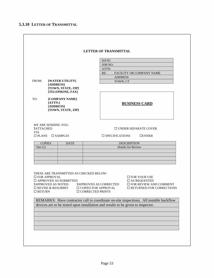
Page 53
5.3.10 LETTER OF TRANSMITTAL
LETTER OF TRANSMITTAL
DATE: JOB NO. ATTN: RE: FACILITY OR COMPANY NAME ADDRESS TOWN, CT
BUSINESS CARD
WE ARE SENDING YOU: ATTACHED UNDER SEPARATE COVER
VIA PLANS SAMPLES SPECIFICATIONS OTHER
COPIES DATE DESCRIPTION
One (1) Details for Review
THESE ARE TRANSMITTED AS CHECKED BELOW: FOR APPROVAL FOR YOUR USE APPROVED AS SUBMITTED AS REQUESTED
APPROVED AS NOTED: APPROVED AS CORRECTED FOR REVIEW AND COMMENT REVISE & RESUBMIT COPIES FOR APPROVAL RETURNED FOR CORRECTIONS RETURN CORRECTED PRINTS
REMARKS: Have contractor call to coordinate on-site inspections. All testable backflow devices are to be tested upon installation and results to be given to inspector.
FROM: [WATER UTILITY] [ADDRESS] [TOWN, STATE, ZIP] [TELEPHONE, FAX] TO: [COMPANY NAME] [ATTN:] [ADDRESS] [TOWN, STATE, ZIP]

Page 54
5.3.11 ANNUAL TESTING NOTIFICATION LETTER
ANNUAL TESTING NOTIFICATION LETTER
DATE FACILITY NAME Facility # NAME ADDRESS TOWN Dear _____: Annual testing of backflow prevention devices is required by both Section 19-13-B38a of the Regulations of Connecticut State Agencies and The Ordinances of the [WATER UTILITY] (copy attached). Annual test results must be forwarded to the [WATER UTILITY]. The owner of the premises where a testable backflow device exists, shall, when the device is first installed and annually thereafter, have the device tested by a State of Connecticut certified backflow prevention device tester. All costs associated with installation, repair, and testing of backflow devices is the responsibility of the owner. Our records for the calendar year 2000 indicate that, all or some, of the testable backflow devices located at the above captioned facility have not been tested. Please arrange for a State of Connecticut certified backflow tester, (list enclosed) to test each device and submit the results to this office within 30 days of the receipt of this letter. Should you not have each backflow device tested and the report submitted to [WATER UTILITY] by December 31, 2000, a letter of non-compliance will be forwarded to both the Local and State Health Departments. Please note that any removal or relocation of a testable backflow device must have prior approval from this office. In the event that a testable device has been removed or relocated, an inspection of the facility by the [WATER UTILITY] is required to determine if the facility is in compliance. If devices at your facility have been tested and reports have been sent to the [WATER UTILITY], or you have any further questions, please contact [INSPECTOR] at [TELEPHONE NUMBER]. Sincerely, NAME TITLE cc: Local Health Dept. State of CT DPH

5.3.12 ANNUAL TESTING FINAL NOTICE LETTER
FACILITY NAMNAME ADDRESS TOWN Dear _____: Annual testing of Regulations of Co(copy attached). A The owner of the installed and annbackflow preventibackflow devices Our records for thlocated at the aboConnecticut certifthis office within Should you not haUTILITY] by MaState Health Depa Please note that anfrom this office. Iof the facility by tcompliance. If devices at your UTILITY], or yoNUMBER].
ANNUAL TESTING FINAL NOTIFICATION LETTER
DATE
E Facility # FINAL NOTICE
backflow prevention devices is required by both Section 19-13-B38a of the nnecticut State Agencies and The Ordinances of the [WATER UTILITY] nnual test results must be forwarded to the [WATER UTILITY].
premises where a testable backflow device exists, shall, when the device is first ually thereafter, have the device tested by a State of Connecticut certified on device tester. All costs associated with installation, repair, and testing of is the responsibility of the owner.
e calendar year 1999 indicate that, all or some, of the testable backflow devices ve captioned facility have not been tested. Please arrange for a State of ied backflow tester, (list enclosed) to test each device and submit the results to 30 days of the receipt of this letter.
ve each backflow device tested and the report submitted to [WATER y 15, 2000, a letter of non-compliance will be forwarded to both the Local and rtments.
y removal or relocation of a testable backflow device must have prior approval n the event that a testable device has been removed or relocated, an inspection he [WATER UTILITY] is required to determine if the facility is in
facility have been tested and reports have been sent to the [WATER u have any further questions, please contact [INSPECTOR] at [TELEPHONE
Page 55
Page 56
6 FACILITIES TO BE INSPECTED
The list of facilities to be inspected may vary as to the degree of hazard and is subject to the inspector's judgment. After each facility listed, there is an indication of whether the premises need to be inspected every year or every 5 years, and if an RPD or DCVA is required on the main line. In areas where use of toxic or objectionable substances can be isolated, an RPD would only be required in that area. This list of facilities is submitted as a guideline.
Animal Hospitals 1 Beauty Salons -Barber Shops -Beauty Schools 1 Car Washes 1, RPD Commercial Laundries and Dye Works 1, RPD Convalescent and Nursing Homes 1, RPD Doctors' and Dentists' Offices 1, RPD Fire Sprinkler Systems (with chemicals added) 1, RPD Fire Sprinkler Systems (with Siamese connection) 5, DCVA Food Processing 1, RPD Funeral Homes and Mortuaries 1, RPD Gas Storage 1 Greenhouses 1, RPD Hospitals 1, RPD Irrigation Systems (with chemicals injected) 1, RPD Marinas -Yacht Clubs –Docks 1, RPD Medical Laboratories 1, RPD Photo Developers 1 Plating and Chemical Companies 1, RPD Potable Water Tanks 5 Radiator Repairers 1 Restaurants (see facility descriptions) Schools –Universities 1 Sewage Plants, Pump Stations and Waste Reduction Facilities 1, RPD Solar Heat Systems 1 Swimming Pools 5 Tank Trucks -Tree Sprayers 1, RPD Wells or Auxiliary Supplies 5
6.1 COMMON INSTALLATIONS
There are several hazards which require cross connection protection that are found in many facilities regardless of the specific activities conducted on the premises. These include such common items as boilers, fire sprinklers systems, irrigation system, toilets and urinals, janitor sinks and other hose connections, etc. Since these are encountered frequently, they will not be identified in each facility description in the following section. The recommended protections outlined below should be required wherever these hazards are found.
6.1.1 BOILERS Boilers are a concern because chemicals are often added or the water is otherwise rendered non-potable. If there was a loss of pressure in the system, this non-potable water could enter the plumbing system. If the facility operator is uncertain as to whether or not chemicals are or have been added, protection should be required.
Appropriate Protection: RPD on boiler feed

Page 57
6.1.2 FIRE SPRINKLER SYSTEMS Fire Sprinkler systems are a concern because the pressure and volume demands in a fire emergency can draw non-potable water into the public water supply system. RPD protection is required on a line to any fire sprinkler system if chemicals are added. A DCVA is required on a fire sprinkler system with a Siamese connection.
Appropriate Protection: RPD on system where chemicals are added RPD on new system with Siamese connection
DCVA on existing system with Siamese connection See “Cross Connection Control Facts for Fire Sprinkler Systems” in Appendix A.
6.1.3 IRRIGATION/LAWN SPRINKLER SYSTEMS Irrigation systems are a concern because of the likelihood that chemicals will be added to the system or applied to the ground. This would include any pesticides, herbicides, or fertilizer applications. When chemicals are applied to the ground they may be introduced into the water system through the inlets on inground sprinkler heads.
Appropriate Protection: RPD on sprinkler system with chemical injection, vacuum breaker on all other systems. NOTE: The design of the lawn sprinkler system may require a PVB instead of an atmospheric vacuum breaker.
6.1.4 TOILETS OR URINALS Toilets and urinals are a concern because of the nature of the wastewater and the indirect connection to the sewage system. Each toilet or urinal should he equipped with backflow prevention devices. Appropriate Protection: Flush valve toilet or urinal -vacuum breaker. Tank toilet –Antisiphon ball
cock Hose Connections
6.1.5 HOSE CONNECTIONS Hose connections are a concern because of the possibility that they may become submerged in a contaminated, non-potable liquid. If the hose inlet is submerged and there is a loss of pressure, backsiphonage could occur, drawing the contaminated supply into the system. The connections are common on janitor wash sinks where hoses are attached to fill or rinse buckets with cleaning solutions and other chemical mixtures. These connections are also found on laboratory sinks where the hoses may come in contact with solution containing chemical biological hazards. Appropriate Protection: Vacuum Breakers
Hose bibb vacuum breaker on all threaded faucets Laboratory faucet vacuum breaker on lab sinks
6.1.6 AIR CONDITIONING UNITS, HEAT EXCHANGERS, AND OTHER WATER COOLED EQUIPMENT Air conditioning units, heat exchangers and other water cooled equipment are a concern because they may be connected to the sewer system, may be contaminated with algae or bacterial slime, or may be treated with chemicals. These units are found in numerous types of facilities and require backflow protection to prevent introduction of the contaminated water into the potable water system.
Appropriate Protection: Air gap or RPD

Page 58
6.1.7 AUXILIARY SOURCES No physical connection shall be permitted between the distribution system of a potable public water supply and that of any other water supply, unless the other water supply is of safe, sanitary quality and the interconnection of both supplies is approved by the State Department of Public Health. A water supply for industrial or fire protection purposes, obtained entirely or in part from a source not approved for drinking purposes, shall be distributed through an independent piping system having no connection with the systems for drinking or for other domestic use.
Appropriate Protection: Physically disconnected, independent distribution systems unless source is approved by DPH for interconnection. An RPD is also required if auxiliary source contains toxic or objectionable substances.
6.2 FACILITY INSPECTIONS The requirements for backflow prevention devices are dictated by Section 19-13-B38a of the RCSA. The selection of the appropriate device in a particular installation depends on the degree of hazard present and the type of equipment where the device is to be installed. In many cases the inspector must make a recommendation for installation based on the specific situation using the regulation and technical guidelines. The following section provides a guide to interpret the regulations identifying (1) facilities to be inspected; (2) common installations; (3) facility descriptions; and (4) equipment to be inspected. In all cases the regulations in the RCSA would supersede any guidance documents and be the absolute determinant of the requirements. Questions or serious conflicts should be referred to the Department of Public Health, Water Supplies Section for interpretation.
6.2.1 SEWAGE PLANTS, PUMP STATIONS AND WATER REDUCTION FACILITIES The hazards normally found in plants of this type include cross connections between the public water supply and:
(1) sewage pumps for priming, cleaning, flushing or unclogging purposes; (2) water operated sewage sump ejectors; (3) chlorinators using potable water when disinfecting waste water; (4) sewer lines for purpose of disposing of filter or softener backwash water or water from cooling systems.
6.2.2 PLATING AND CHEMICAL COMPANIES The hazards normally found in plants of this type include cross connections between the public water supply and:
(1) plating facilities involving the use of highly toxic cyanides, heavy metals in solution, acids and caustic solutions;
(2) plating solution filtering equipment with pumps and circulating lines; (3) tanks, vats or other vessels used in painting, descaling, anodizing, cleaning, stripping, oxidizing, etc. for
the preparation or finishing of products; (4) steam generating facilities and lines which may be contaminated with boiler compounds; (5) water cooled equipment which may be sewer connected such as compressors, heat exchangers, and air
conditioning equipment.

Page 59
6.2.3 HOSPITALS The hazards normally found in facilities of this type include cross connections between the public supply and:
(1) contaminated or sewer-connected equipment such as bedpans washers, flush valve toilets and urinals, autoclaves, specimen tanks, sterilizers, aspirators, autopsy and mortuary equipment laboratories;
(2) sewer lines for the purpose of disposing of filter or softener backwash water; (3) water cooled equipment such as compressors, heat exchangers, air conditioning equipment, etc; (4) high pressured coil systems; (5) cooling towers which may be heavily contaminated with bird droppings, vermin, algae, etc., or with toxic
water treatment compounds; (6) steam generating facilities and lines; (7) kitchen and food processing equipment including dishwashers, ice makers, carbonated beverage
machines; (8) hemodialysis units; (9) auxiliary emergency water supplies.
6.2.4 CONVALESCENT AND NURSING HOMES The hazards normally found in facilities of this type include cross connections between the public water supply and:
(1) contaminated or sewer connected equipment such as bedpan washers, flush valve toilets, urinals and whirlpool baths;
(2) kitchen and food processing equipment including dishwashers, ice makers, carbonated beverage machines;
(3) auxiliary emergency water supplies.
6.2.5 FUNERAL HOMES AND MORTUARIES The hazards normally found in this type of facility include cross connection between the public water supply and:
(1) prep room equipment such as hose connections and aspirators; (2) boilers with chemicals added
6.2.6 SCHOOLS AND UNIVERSITIES The hazards normally to be found in a facility of this type include cross connections between the consumer's water system and:
(1) contaminated and/or sewer connected facilities such as inadequately protected flush valve toilets, urinals, aspirators, retorts, pipet tube washers, etc.;
(2) laboratory equipment which may be chemically or bacteriologically contaminated; (3) steam sterilizers, autoclaves, specimen tanks, autopsy and morgue equipment; (4) sewer connected plumbing fixtures such as flush valve toilets and urinals; (5) steam generating facilities and lines which may be contaminated with boiler compounds; (6) water cooled equipment which must be sewer connected such as compressors, heat exchangers, air
conditioning equipment, etc.
Page 60
(7) high pressured coil systems; (8) irrigation systems which may be equipped with pumps, injectors, or other facilities for injecting
chemicals or subject to contamination from submerged inlets, auxiliary water supplies, or polluted or contaminated waters;
(9) tanks, automatic film processing machines or facilities; (10) auxiliary water supplies; (11) lab sinks and other hose connections.
6.2.7 MEDICAL LABORATORIES The hazards normally found in this type of facility are cross connections between the public water supply and:
(1) lab sinks and hose connections; (2) pipet washers, sterilizers, autoclaves, etc.; (3) sewer lines for the purpose of disposing of samples, etc.; (4) filter equipment, deionizers, membrane filters, distillers.
6.2.8 CAR WASH FACILITIES The hazard normally found with this type of facility would be a cross connection between the public water supply and:
(1) the scrubber and rinser plumbing, which would enable a recirculating pump to force recycled water back into the public water supply;
(2) water booster pumps.
6.2.9 ANIMAL HOSPITALS, GROOMING ESTABLISHMENTS The hazards normally found in this type of facility would be a cross connection between the public water supply and:
(1) bath tubs where animals are washed with chemicals for treatment of fleas, skin disorders, etc.; (2) hoses used to wash wastes from pens and run areas; (3) medical equipment such as X-ray development.
6.2.10 POTABLE WATER TANKS The hazards normally associated with this type of facility would be a cross connection between the public water supply and:
(1) water pumped with a booster pump and held in a storage reservoir for use (i.e. on upper floors of a multi-storied buildings) which could backflow into the potable system with a loss in pressure in the distribution main.
6.2.11 MARINAS, YACHT CLUBS AND DOCKS The hazards normally found in water front facilities include cross connections between the public water supply and:
(1) outlets available for supplying water to docks using common garden hoses;

Page 61
(2) large supply lines used to supply drinking water for larger seagoing vessels; (3) swimming pools;
(4) kitchen/restaurant facilities such as dishwashers, ice machines, carbonated beverage machines; (5) gas tanks which hydraulically raise gas levels; (6) cooling towers; (7) fire protection systems; (8) high pressure washing systems; (9) motor testing tank with bottom feeds.
6.2.12 SWIMMING POOLS The hazards normally found at swimming pools are cross connections between the public water supply and:
(1) below rim inlets; (2) hoses left running and dropped into the pool; (3) direct connections at the chlorination equipment; (4) steam generating facilities and lines which may be contaminated with boiler compounds.
6.2.13 GREENHOUSES The hazards normally found at greenhouses are cross connections between the public water supply and:
(1) chemical injectors; (2) irrigation systems; (3) hoses left running on the floor or in planters where there is a possibility of backsiphonage; (4) steam generating facilities which may be contaminated with boiler compounds.
6.2.14 TANK TRUCKS AND SPRAYERS The hazards normally found with tank trucks and sprayers is a cross connection between the public water supply nd: a
(1) a fill pipe which becomes submerged in the tank during filling. (2) hydroseeders, sweepers, sewer vacuums, sewer rodders or lawn maintenance equipment which may be
subject to backsiphonage during use.
6.2.15 AUTOMOBILE OR RADIATOR REPAIR FACILITIES The hazards normally found with these types of facilities are cross connections between the public water supply and:
(1) submerged inlets into testing tanks where chemicals are present; (2) rinse hoses lying on the floor stuck into tanks; (3) steam generating lines which may be contaminated with boiler compounds.

Page 62
6.2.16 PHOTO DEVELOPERS The hazards normally found in this type of facility are a cross connection between the public water supply and:
(1) tanks or automatic film processing machines which may be contaminated with chemicals
6.2.17 LAUNDRIES, DRY CLEANERS AND DYE WORKS The hazards normally found in this type of facility are cross connections between the public water supply and:
(1) laundry machines having under rim inlets; (2) steam generating facilities which may be contaminated with boiler compounds; (3) water storage tanks equipped with recirculating pumps; (4) dye vats using chemicals; (5) high pressure coil heat exchangers; (6) sewer connected compressors; (7) dry cleaning equipment with solvents and heat exchangers.
6.2.18 SOLAR HEATING SYSTEMS The hazards normally found with solar heating and/or cooling systems include cross connections between the public water supply and:
(1) reservoirs and/or solar collector fluids which may have antifreeze, toxic corrosion inhibitors, or nonpotable water;
(2) single wall heat exchanges between the consumer's water and non-potable water or fluids; (3) negative pressure zones created by circulation pumps.
6.2.19 FOOD PROCESSING SUCH AS BOTTLING COMPANIES, CANNERIES & MEAT PACKING The hazards normally found in this type of facility would be cross connections between the public water supply and:
(1) steam connected facilities such as pressure cookers, autoclaves, retorts, etc.; (2) equipment used for washing, cooking, cleaning, blanching, flushing or fluming or for transmission of
foods; (3) fertilizers or wastes; (4) can and bottle washing machines and lines where caustics, acids, detergents, and other compounds are
used in cleaning, sterilizing, etc; (5) cooling towers and circulating systems which may be contaminated with bird droppings, vermin, algae,
bacterial slimes, or with toxic water treatment compounds; (6) steam generating facilities and lines which may be contaminated with boiler compounds.
6.2.20 BEAUTY SALONS -BARBER SHOPS -BEAUTY SCHOOLS The hazards normally found in these facilities are cross connections between the public water supply and:
(1) hair wash sinks that have hoses for rinsing hair during washing, dying or other chemical treatments

Page 63
6.2.21 DOCTOR’S AND DENTIST’S OFFICES The hazards normally found in these facilities are cross connections between the public water supply and:
(1) autoclaves; (2) specimen tanks; (3) sterilizers; (4) aspirators; (5) laboratory sinks; (6) dental suction hoses; (7) X-ray equipment; (8) air compressor lines; (9) water cooled equipment such as air conditioning equipment which may be connected to sewers.
See 7.11 “Backflow Prevention at Dental Offices – Fact Sheet” on pages 79 and 80.
6.2.22 RESTAURANTS AND FOOD ESTABLISHMENTS The hazards normally found in these types of facilities would be cross connections between public water supplies and:
(1) dishwashing sinks particularly with detergent injectors; (2) deep sinks with aspirators with soaps, detergents, etc. (3) janitorial sinks; (4) toilets and urinals; (5) air conditioning units piped directly to sewers; (6) steam generating facilities which may be contaminated with boiler compounds; (7) water cooled equipment such as air conditioners, which may be connected to the sewers; (8) garbage can washers; (9) garbage disposal units; (10) soda equipment, expresso boilers with salt filters; (11) lawn sprinklers.
See “2001 Updated Guideline for Correcting Plumbing Hazards and Cross Connections in Food Establishments” in Appendix B.

Page 64
6.3 EQUIPMENT TO BE INSPECTED This Section is included to assist the inspector in selecting the proper device to correct violations on certain installations. The chart provides guidance based on the RCSA. An air gap would be acceptable in any situation, however, this column is only checked where an air gap would usually be feasible. It should be noted that any device which provides a greater degree of protection, than the required device, would be allowable (e.g. an RPD could be used in place of a vacuum breaker). Nevertheless, this may increase the cost considerably and other devices should not be recommended unless there is appropriate cause. The list includes those situations which will normally be encountered. Should any unique situation arise where the inspector cannot determine the proper device to use, the State Department of Public Health, Drinking Water Division, should be contacted.

Page 65
Backflow Prevention Devices Abbreviated Terms
A.G. – Air Gap A.V. – Air Vent Type Backflow Preventer D.C.V.A. – Double Check Valve Assembly R.P.D. – Reduced Pressure Principle Backflow Preventer V.B. – Vacuum Breaker (Atmospheric, Pressure, Hose Bibb, etc.)
DEVICES EQUIPMENT A.G. R.P.D. A.V. V.B. D.C.V.A.
Aspirator X Auxiliary Water System X Bedpan Washer X Boiler (chemicals added) X Boiler (no chemicals) X X Carbonator (soda machine) X Cash Wash X Chlorinator or Other Chemical Injection System X Cooling Tower X X Dental Equipment X Film Processing Equipment X Fire Sprinkler System (chemicals added) X Fire Sprinkler System (w/Siamese connection, no chemicals)
X
Flush Valve Toilet X Garbage Can Washer X X Garbage Disposal X X Gas Storage (under pressure) X Hair Wash Sink X Heat Exchanger (chemicals added – single wall) X Heat Exchanger (no chemicals – single wall) X X Heat Exchanger – Vented Double Wall Hemodialysis Unit X X X Ice Machines X X Irrigation/Lawn Sprinkler (chemicals added to system) X Irrigation/Lawn Sprinkler (no chemicals) X Laboratory Sinks X Laundry Machines X X Marina, Dock X X Plating or Dye Tanks, Vats X X Pressurized Water System (ship) X Sewage Pumps/Sewage – Connected Equipment X Service Line (toxic or objectionable substance) X Soap Injector X Solar System (chemicals added) X Solar System (no chemicals) X X Steam Generating Equipment X Storage Tank (fire protection, no chemicals) X X Submerged Inlet X Tank Truck (lawn care, sweeper) X X X Water Cooled Equipment X X Water Treatment Equipment X X X-Ray Developer X

Page 66
7 REGULATORY CLASSIFICATION LETTERS AND STATEMENT
7.1 REGULATION CLARIFICATION - SECTION 19-13-B38a (c) (1) OF THE RCSA

Page 67

Page 68
7.2 REGULATION CLARIFICATION - SECTION 19-13-38a (c) (1) OF THE RCSA

Page 69
7.3 TRAP PRIMERS – REGULATION CLARIFICATION
WATER SUPPLIES SECTION
TRAP PRIMERS BACKGROUND: Trap Primers are installed to maintain the trap seal in areas subject to high rates of evaporation (e.g floor drains). The purpose of maintaining the trap seal is to prevent the entrance of sewer gas to the building. The State of Connecticut Basic Building Code allows these devices and many local building officials require them. Section 19-13-B45 of the RCSA requires that plumbing systems be constructed to avoid contamination of safe drinking water systems. Cross connections between supply and drainage systems are prohibited. PROCEDURE: Trap primers, installed on public water system lines, would be allowed under the RCSA provided that the following conditions are met: 1. The trap primer should meet American Society of Sanitary Engineering (ASSE) Standard 1018 - Trap
Seal Primer Valves. 2. The trap primer should be installed where it is accessible for inspection and repair.
Note: In addition to our concern about cross connections, we also are concerned that if the device does not function properly, it could waste water unnecessarily.
3. The trap primer should be installed at least six (6) inches above the grid of a floor drain or the flood rim
of the equipment which the trap is to serve. Greater installation height is required if specified by the manufacturer.
4. The water utility must inspect the device when it conducts its cross connection survey. 5. The device should not be used for anything other than its intended use as a trap primer. Effective Date: May 24, 1994 Revised: August 12, 1997
Page 70
7.4 CONTAMINATED PRIVATE WELL – REGULATION CLARIFICATION
WATER SUPPLIES SECTION
CONTAMINATED PRIVATE WELL
ABANDONMENT & INTERCONNECTION TO PUBLIC SUPPLY
A private well owner, with a contaminated well who elects to receive water service from a public water system main, should abandon the contaminated well in accordance with the Connecticut Well Drilling Code [Regulations of Connecticut State Agencies Sections (RCSA) 25-128-56 and 25-128-57]. In the event the private well owner decides to retain the contaminated well for non-domestic water use, the following apply: 1. The public water service line to the building shall be equipped with a Reduced Pressure Device (RPD)
pursuant to Section 19-13-B38(c)(1) of the RCSA; and, 2. The private well water system (i.e. well, pump and tank) shall be physically disconnected from the
building plumbing pursuant to Section 19-13-B37(a) of the PHC; and, 3. The public water system shall test the RPD annually and inspect the physical disconnection at least once
every five years (5) pursuant to Sections 19-13-B38(e)(6) and 19-13-B102(f) (2) of the PHC. Revised date: 8/12/97

Page 71
7.5 WASHING MACHINES – REGULATION CLARIFICATION
September 16, 2002 Mr. Mark Hanson, Manager of Utility Services Metropolitan District Commission 555 Main Street. P.O. Box 800 Hartford, CT 06142-0800 Dear Mr. Hanson: I am writing in response to your letter of August 28, 2002 concerning backflow prevention on washing machines at hospitals and nursing homes. I would first like to note that we discussed the issue of tempered water at these types of institutions with this department’s Division of Health Care Systems. This division regulates nursing homes and hospitals. The water is tempered for water available to patients only. Water for washing machines is adjusted to the temperature recommended by the manufacturer of the machines. This is usually greater than 1400 F. and is checked by the department’s inspectors. In response to your question on the protection required, Section 19-13-B38a(e) of the Regulations of Connecticut State Agencies requires an air gap or vacuum breaker in this situation. This would only be the case if there is not a potential for backpressure. The elevation of atmospheric vacuum breakers is based on the manufacturer’s instructions according to Section 13-B38a(f)(8). It is not based directly on the ASSE standards. Sincerely, Robert W. Rivard, P.E. Supervising Sanitary Engineer Water Supplies Section

August 28, 2002 Robert Rivard Dept. of Public Health 410 Capitol Ave., MS #51 WAT P.O. Box 340308 Hartford, CT 06134 Dear Bob: On August 27th I met with Ed Forcier and Dana Dube to take a thorough look at commercial dishwashers and washing machines. The various types of dishwashers met code with vacuum breakers. The washing machines presented many different scenarios. Many top fed washing machines either had a vacuum breaker or were air gap fed. The large bottom fed washing machines appear to be the greatest concern. The machines located in hospitals and nursing homes have a higher degree of human wastes, disease, etc. associated with them. Should these machines in these locations be addressed with a higher measure of concern and be afforded a higher degree of protection? It was pointed out that many institutions are using a tempered water of no more than 120 degrees. The question was raised if this temperature is high enough to kill harmful bacteria and disease. A consistent policy is needed on protection of commercial washing machines. I know time is getting short to our next committee meeting but we would appreciate your input on the following questions. • Should we have a concern that bacteria and disease in certain institutions is more prevalent and
requires a higher degree of protection? • Is a temperature of no more than 120 degrees a problem with the elimination of most bacteria
and disease? • If the first two questions are of no concern is a vacuum breaker still acceptable for the
submerged inlet in a commercial washing machine? Also it was brought to my attention that according to ASSE, any vacuum breaker installed by the manufacturer only has to be 3” above the highest outlet. Is this ASSE standard accepted by DPH? As always your input is greatly appreciated.
Sincerely, Mark A. Hanson Manager of Utility Services Department of Engineering & Planning
Page 72

7.6 LETTER – INTERMEDIATE AIR VENT BACKFLOW PREVENTER
February 21, 2002 Mr. Edward Forcier, Operations Second Taxing District Water De164 Water Street P.O. Box 468 South Norwalk, CT 06856-0468 Dear Mr. Forcier: I am writing in response to yourvent backflow preventers (air venthe Regulations of Connecticut specified in the regulations are towner can install a different devor better protection. Section 19-13-B38a(e) requires could be substituted since it prAmerican Society of Sanitary Enrevision of this section of the reg Sincerely, Robert W. Rivard, P.E. Supervising Sanitary Engineer Water Supplies Section
Telep
P
STATE OF CONNECTICUTDEPARTMENT OF PUBLIC HEALTH
Supervisor partment
letter of February 13, 2002 concerning the use of intermediate air t type backflow preventer as defined in Section 19-13-B38a(a)(2)of
State Agencies). The devices and methods of backflow prevention he minimum protection required. Unless specifically prohibited, an ice than the one required by the regulations, if it provides equivalent
a vacuum breaker or an gap. An air vent type backflow preventer ovides equivalent protection in accordance with standards of the gineers. This is an area that my need to be clarified during a future ulations.
hone410
.O. BAn
Phone: (860) 509-7333 Device for the Deaf (860) 509-7191 Capitol Avenue - MS # 51WAT ox 340308 Hartford, CT 06134 Equal Opportunity Employer
Page 73

Page 74
7.7 HOME BOOSTER PUMPS – RECOMMENDED PROCEDURE
WATER SUPPLIES SECTION
HOME BOOSTER PUMPS
Home booster pumps have been used in the past to add customers on water lines that cannot provide adequate water pressure. Pursuant to Section 19-13-B102(f)(1) of the RCSA, a minimum of 25 pounds per square inch (psi) shall be provided at the main under normal conditions unless a special provision is made. Individual home booster pumps are to be used as a special provision in specific individual cases where: 1. The building to be served is an excessive distance from the street main or its elevation precludes adequate
water pressure and, there is at least 25 psi in the street main or; 2. The public water system signs a Consent Order with this Department to upgrade its water distribution
system to the affected area by the installation of larger mains or additional booster stations, or by some other long term solution. In this case, the pressure in the main is less than 25 psi.
3. Water pressure in the main is more than 25 but less than 35 psi. In this case, the DPUC must initially
authorize the installation for systems that fall under the 16-262m requirements. Where an individual booster pump is used the installation shall: a. Have an air vent type backflow preventer installed on the line to the booster pump, unless the
public water system determines that conditions warrant the installation of a reduced pressure principle backflow preventer and;
b. Have low water cut-off switches. All such special provisions pursuant to 19-13-B102(f)(1) shall be reviewed and approved by the Department before installation. Revised 8/18/97

Page 75
7.8 MAKE-UP WATER LINE RECOMMENDED PROCEDURE
WATER SUPPLIES SECTION
MAKE-UP WATER LINE FOR CHEMICAL TREATMENT, CROSS CONNECTION PROTECTION For the purpose of this recommendation, the Make-up Water Line is defined as any water line connected to a public potable water supply which may supply dilution water for chemical treatment or process purposes (e.g. dilution water for flushing, day tank solution preparation or carrying water for chemical feed lines). The Make-up Water Line must have either a reduced pressure principle backflow preventer (RPD) in a location covering all chemical treatment systems, or a vacuum breaker, RPD, or physical air gap protection for each chemical mixing tank or individual treatment system. In the event that a chemical solution is used for pre and post treatment, separate chemical feed systems, with no interconnecting piping, are necessary. In new treatment stations or in an upgrade of an existing treatment station, it is recommended that the make-up water line be a dedicated line serving only the treatment and process systems. Safety eyewash, showers and water fountains, etc. should not be supplied by this line. There must be an RPD or air gap on the dedicated line to all chemical treatment systems. It is recommended that in addition to the RPD or air gap there be a vacuum breaker or physical air gap at each chemical mixing tank on this line. Note: If vacuum breaker protection is provided on the treatment system, it must be installed pursuant to the
RCSA Regulation 19-13-B38a and in accordance with the current edition of the “State of Connecticut Cross Connection Control Manual” and manufacturer’s recommendations.
Effective Date: September 1, 1990 Revised: August 12, 1997

Page 76
7.9 ENFORCEMENT OF CROSS CONNECTION CONTROL REGULATIONS – GUIDANCE
DOCUMENT
WATER SUPPLIES SECTION
ENFORCEMENT OF CROSS CONNECTION CONTROL REGULATIONS PURPOSE: To ensure a consistent process for the enforcement of RCSA regulations (such as, but not limited to, Sections 19-13-B37, 19-13-B38a, 19-13-B39, 19-13-B45 and 19-13-B51c). The process will combine the efforts of public water systems, local health departments and the Department of Public Health (DPH) in a progressive step approach to protect the public health from contamination of public water systems through cross connections. OUTREACH: The DPH shall make public water systems and local health departments aware of this enforcement process and the appropriate responsibilities for each party through mailings and through participation at ongoing forums. PROCESS: The following process shall be followed: 1. The public water system shall perform inspections pursuant to PHC Sections 19-13-B102 and 19-13-B37. 2. The public water system shall take reasonable efforts to have the customer correct outstanding violations.
Reasonable efforts shall include documenting the violation and providing technical assistance to the customer. If the public water system has the authority to terminate service for cross connection violations, it may utilize this authority, as appropriate, and notify the local health department.
3. If the public water system is not successful in resolving violations utilizing item # 2 (above), it shall contact
the local health department for enforcement of the PHC pursuant to Section 19a-207 of the Conn. General Statutes. This section states that the local director of health shall enforce or assist in the enforcement of the PHC and the regulations adopted by the Commissioner of Public Health. (see statutory text at the end of this document).
4. When necessary, the local director of health and/or the public water system shall notify the DPH, Drinking
Water Division (DWD) of unresolved violations, in writing, to request action. 5. The DWD will verify that the public water system has taken reasonable efforts, including notification to the
local health department, to have the customer correct outstanding violations. If appropriate, the DPH will proceed with the next steps.
6. The DPH shall contact the local health department to discuss the violation, any actions taken to date and
request them to issue an order to the customer to correct the violation.
Page 77
7. The DPH may also issue an order to the water system to terminate service and/or an order to the customer to correct the violation by eliminating the cross connection or installing an appropriate backflow prevention device in accordance with the PHC. For violations on fire sprinkler systems, the DPH may assess a civil penalty against the owner of the sprinkler system.
Effective Date: March 13, 2000 Connecticut General Statutes Section 19a-207. (Formerly Sec. 19-80). Duties of local officials. Emergencies. Regulations. The local director of health or his authorized agent or the board of health shall enforce or assist in the enforcement of the RCSA and such regulations as may be adopted by the Commissioner of Public Health. Towns, cities and boroughs may retain the power to adopt, by ordinance, sanitary rules and regulations, but no such rule or regulation shall be inconsistent with the RCSA as adopted by said commissioner. In any emergency when the health of any locality is menaced or when any local board of health or director of health fails to comply with recommendations of the Department of Public Health, said department may enforce such regulations as may be required for the protection of public health.

Page 78
7.10 INTERRUPTION OF WATER SUPPLY – GUIDANCE DOCUMENT
WATER SUPPLIES SECTION
INTERRUPTION OF WATER SUPPLY - WATER QUALITY
If an interruption in public water service resulting in a water outage to any consumer occurs, the public water supply must notify the Department of Public Health and all applicable local health departments in accordance with Section 19-13-B46 of the RCSA, and the Department of Public Utility Control (if applicable), as soon as possible. Every effort to re-establish service with the shortest possible delay consistent with the safety of the consumers and the general public must be made. Whenever an unplanned interruption in water service occurs (i.e., source failures, power outages, main breaks, etc.), a set of circumstances is created that poses a threat to water quality. Atmospheric and negative pressures created in the distribution system can permit ground and surface water to enter the system via joints, cracks, and holes in the piping network and set the stage for cross connections to contaminate the system. Despite a public water supply’s best efforts to ensure a tight distribution network free of cross connections, no system can be totally immune from the threat of a water quality problem in the event of water service interruption. Every effort to avoid outages should be implemented as the best safeguard against this threat. However, should an unplanned outage occur, the following procedures should be followed: UNCHLORINATED SYSTEMS: When an unplanned interruption in service water occurs for any reason in any unchlorinated system or portion of such system, the following precautions should be implemented: a. Consumers are to be notified of the interruption and precautionary measures, such as boiling the water
used for drinking and cooking at a rolling boil for at least five minutes or water should be obtained from an alternate potable source (i.e., bottled water) until notified that the water is safe to drink.
b. After repairs are made, the distribution system should be disinfected properly in accordance with
AWWA Standards. c. Distribution water samples should be collected as soon as chlorine residual has dissipated and analyzed
for coliform bacteria and heterotrophic plate count (HPC). d. If the coliform bacterial results are negative, consumers should be notified that the water is safe to
consume; however, if the results are unsatisfactory, boiling notices should remain in effect, the Water Supplies Section of the Department of Public Health should be notified, and chlorination of the system implemented. Consumers should be notified that the water is safe to consume only after all chlorine has been flushed from the system and distribution samples of unchlorinated water indicate satisfactory bacterial results.
CHLORINATED SYSTEMS: When an unplanned interruption in water service occurs for any reason in any continuously chlorinated system, the following precautions should be implemented: a. Consumers should be notified of the interruption. b. After repairs are made, the repaired area should be disinfected in accordance with AWWA standards. c. Upon resumption of water service, chlorine dosage rates should be increased as a precaution against
increased chlorine demand due to the possible introduction of bacteria and sediments into the system.

Page 79
d. Free chlorine residuals should be tested at remote areas of the system and chlorine dosages increased
until at least a 0.2 mg/1 residual is detected at all points in the system. e. If a free chlorine residual cannot be maintained:
(i) Consumers should be notified that all water used for drinking and cooking should be boiled at a rolling boil for at least five minutes or water should be obtained from an alternate potable source (i.e., bottled water) until notified that the water is safe to drink.
(ii) Distribution water samples should be collected immediately in the areas of inadequate chlorine residual and analyzed for coliform bacteria and HPC.
(iii) If the coliform bacterial results are negative, consumers should be notified that the water is safe to consume; however, if the results are unsatisfactory, boiling notices should remain in effect; and the Water Supplies Section of the Department of Public Health should be notified to discuss further actions.
Revised: 8/18/97

Page 80
7.11 BACKFLOW PREVENTION AT DENTAL OFFICES – FACT SHEET

Page 81

Page 82
8 CASE HISTORIES There are numerous case histories of contamination due to cross connections which have occurred throughout the country. These can be found in various cross connection manuals, references listed in this manual and manufacturer's literature. The following are events that we are aware of that have happened in Connecticut and help to illustrate the need for a cross connection control program. There are probably many other cases which have gone unreported. 1974 While fighting a fire at a marina, a fire department pumped salt water into a public water system through a fire hydrant. Three days of flushing were necessary to clean the system. 1977 A line break caused approximately 500 gallons of cooling tower water containing algacide and corrosion control chemicals to flow into the potable water system. Contamination was restricted to the building. 1980 At a waterfront facility, a vessel testing its salt water pumps had pumped salt water into the public water system. Extensive flushing and chlorination were necessary. A backflow preventer was installed to prevent future occurrences. 1982 A connection was made between a water line and a propane tank to purge the gas tank. Propane entered the water lines through backpressure. Five hundred persons had to be evacuated and two explosions occurred. Follow-up involved extensive flushing, gas monitoring and water testing. 1983 A service line break caused backsiphonage of the toilet tank which contained a bright blue toilet tank cleaner. 1985 At a water treatment plant, hydrofluosilicic acid was siphoned out of a day tank into a clearwell. The problem was caused by a fouled backpressure valve and an antisiphon device which had been valved off. A contractor connected a chemically treated fire sprinkler line to the domestic water system in a building. The problem was discovered after numerous water quality complaints. 1986 Blue water was found in the drinking water in a medical building. The cause was found to be a toilet tank cleaner which was siphoned out through a ballcock valve without an antisiphon valve. A hose connection was made from a janitor sink to a cooling system. Backsiphonage caused glycol
to get into the drinking water system. Several floors of an office building were contaminated with pink water. Extensive sampling and flushing were necessary to resolve the problem. The suspected cause was ethylene glycol from an air conditioning system, which was temporarily cross connected to the drinking water system. It was reported that several people had gotten sick from the water at a time sharing facility. While working on an irrigation sprinkler system, the cold water supply line to the building had been turned off several times. The water from the boiler then apparently backflowed to the drinking water
system.

Page 83
1987 To repair a leak in a pump discharge line from a public water supply well, the line was dewatered. This siphoned the contents of a sodium hypochlorite day tank into the effluent main. Highly chlorinated water was later pumped into the distribution system. Metallic tasting water at a bowling alley was caused by a water line connection to a carbonated soda machine without any backflow protection. The carbon dioxide from the carbonator corroded the copper from the water lines. Approximately two homes near a golf course had excessive air in their water lines. The cause was determined to be the connection of a compressor to the irrigation system at the golf course. While fighting an industrial fire, firemen pumped river water into the distribution system of a public water supply. As a result, all customers had to be notified not to drink the water. Extensive flushing and testing were necessary to resolve the problem. 1988 During a meter replacement, green water was found to be flowing from a house. The cause was
found to be a toilet bowl cleaner and an improper ballcock. 1993 A customer complained of blue water in the bathtub and in ice cubes. Upon investigation, it was found that a toilet tank contained a blue bleach tablet and an improper (not anti-siphon) ballcock had been installed.

Page 84
9 APPENDIX 9.1 APPENDIX A – TECHNICAL INFORMATION ON FIRE SPRINKLER REGULATIONS

Page 85
9.2 APPENDIX B – PLUMBING HAZARDS AND CROSS CONNECTIONS IN FOOD ESTABLISHMENTS
Circular Letter No. DEH 2001-2 TO: Directors of Health Certified Food Inspectors FROM: Roger Mshar Environmental Sanitarian 2 Food Protection Program Steven C. Nattrass Environmental Sanitarian 2 Food Protection Program Robert W. Rivard, P.E. Supervising Sanitary Engineer Water Supplies Section DATE: January 9, 2001 SUBJECT: 2001 Updated Guideline for Correcting Plumbing Hazards and Cross Connections Found in Food Establishments In 1999, circular letter DEH 99-5, a guideline for correcting plumbing hazards and cross connections in food establishments, was distributed to local health departments. The enclosed 2001 updated version, DEH #2001-2, includes additional information on the relatively new standard, ASSE Standard No. 1022, for air vent type backflow preventers for carbonators, and on the existing ASSE Standard No. 1002, for antisiphon fill valves (ball cocks) for tank toilets(see equipment item numbers 3 and 7 and attachments). In addition, a list of antisiphon tank toilet ball cock valves that meet ASSE Standard No. 1002 is included in the appendix to assist in the identification of these devices in tank toilets. The following equipment item numbers that have been highlighted with an asterisk on pages 3 and 4 have been changed:
Equipment Item No. Equipment Description #3 Carbonators for beverage dispensers #7 Tank toilets #7a Tank within a tank toilet #8 Threaded faucets inside and outside of establishments #11(h) Water wash exhaust hoods #12 Nonapproved sources #13 Fire sprinkler system #14 Soda guns #15 Chemical proportioner #17 Water Conditioning Systems
The 2001 updated guideline was prepared by the Food Protection Program and Water Supplies Section with review and assistance provided by the Connecticut Section of the American Water Works Association (AWWA). An upcoming training opportunity for cross connection control is being planned for this spring. Please direct any questions regarding cross-connection control in food establishments to Food Protection Program Staff (860) 509-7297 or the Water Supplies Section (860) 509-7333.

Page 86
2001 Updated Guideline for Correcting Plumbing Hazards and Cross Connections Found in Food Establishments
The following guide has been prepared to assist in the identification and correction of plumbing hazards and cross connections in food establishments. Section 19-13-B42( f ) of the RCSA requires, in pertinent part, that for food service establishments:
“Plumbing shall be so sized, installed and maintained as to prevent contamination of the water supply; as to properly convey sewage and liquid wastes from the establishment to the sewerage or sewage disposal system; and as not to constitute a source of contamination of food equipment or multi-use utensils or create an unsanitary condition or nuisance.”
The relevant item on the form (Inspection Report Food Service Establishments) is item #34: “No cross-connection, backsiphonage, backflow.” This is a four (4) point demerit item. For other food establishment settings (including those regulated by PHC Sections: 19-13-B40, 19-13-B48 and 19-13-B49) equivalent language or interpretations of requirements are provided to protect the water supply, food and food-contact surfaces from sources of contamination conveyed by plumbing systems. Cross Connection Definition The State of Connecticut Department of Public Health “Cross-Connection Control Manual” defines a cross-connection as an actual or potential connection between a public water system (including those serving food establishments) and any other source or system through which it is possible to introduce into the water system any contamination or polluting agent. Sections 19-13-B37 and 19-13-B45 of the RCSA expressly prohibit cross-connections between public potable water systems and non-potable water systems, including those in food establishments. Plumbing Hazards/Cross Connection Control To aid in enforcing the above PHC requirements the following chart provides examples of plumbing hazards and cross-connections frequently found in food establishments and recommended corrections. It should be noted that an air gap may be substituted for any required mechanical cross-connection control device and that a reduced pressure or air vent type device may be substituted for atmospheric vacuum breakers. Devices shall conform to the revision of the American Water Works Association Standard C510, C511 or the revision of the applicable standard of the American Society of Sanitary Engineering. Definitions and descriptions of the cross-connection control devices referred to below may be found in PHC Sec. 19-13-B38a(a)-(e).

Page 87
2001 Updated Guideline for Correcting Plumbing Hazards and Cross-Connections Found in Food Establishments
Equipment Backflow/Backsiphonage Preventer Required in Lieu of Air GapI
1. Boiler with chemicals
added. Reduced pressure device VII (RPD).
2. Boiler with no chemicals added.
Air vent type backflow preventer V (e.g., Watts model 9D).
*3. Carbonators for beverage dispensers.
For devices installed prior to May 27, 1999: Air vent type backflow preventerV which contains 2 spring-loaded check valves plus an atmospheric vent (e.g., Watts model 9BD, or Chudnow model 911 plus 2 check valves, Chudnow Model 914 plus 1 check valve, or Carmun Industries part #77-4030 or part #77-6050 plus 1 check valve). Required backflow preventers must be installed downstream from copper pipes and immediately downstream from a removable in-line 100 mesh screen located in the water pump inlet. (See attachment 2). For new or replacement installations or installations to correct deficiencies (e.g., inadequate number of check valves) on or after May 27, 1999: Air vent type backflow preventer that meets ASSE Standard No. 1022 such as Conbraco 4C-100 and Watts No. SD-3. (See attachments 3, 4 and 5).
4. Ice making equipment. If the inlet to the water reservoir is not air gappedI an atmosphericII or pressure vacuum breakerIII or air vent type backflow preventer V is needed.
5. Lawn sprinkler system If no chemicals are added an atmosphericII or pressure vacuum breakerIII is needed. If supply line is under continuous pressure for 12 or more hours a pressure vacuum breaker is needed. If chemicals are added a reduced pressure device (RPD) is needed.
6. Flush valve toilets. Atmospheric vacuum breakerII.
* 7. Tank toilets Antisiphon ball cock that meets ASSE Standard No. 1002. See Appendix on Page 6 and 7 for list of devices that meet this standard. See attachment 6 for diagram of typical antisiphon ball cock.
*7 a. Tank within a tank toilet
“Flushmate” flushometer tank toilet Models M-101228, M-101500, M101525, M-101526 and M-101550 have approved integral backflow protection. (See attachment 7)
* 8. Threaded faucets inside and outside of establishments.
Hose bibb type vacuum breaker if a hose is attached and no chemicals are added to the system.
9. Preflush hose with a nozzle head that may be submerged. (Normally found in the dishwashing area.)
Atmospheric vacuum breakerII. If the shutoff is downstream from vacuum breaker, a pressure vacuum breaker III or an air vent type backflow preventer V is needed if the line is under continuous pressure for 12 or more hours.
10. Coffee urns. A reduced pressure device is needed if chemicals are added to a jacketed urn. Where the submerged inlet supplies water to an enclosed coffee maker tank for heating the water and the water is intended for downstream consumption no backflow protection is required.
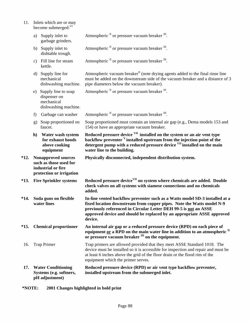
Page 88
11. Inlets which are or may become submerged:VI
a) Supply inlet to garbage grinders.
Atmospheric II or pressure vacuum breaker III.
b) Supply inlet to dishtable trough.
Atmospheric II or pressure vacuum breaker III.
c) Fill line for steam kettle.
Atmospheric II or pressure vacuum breaker III.
d) Supply line for mechanical dishwashing machine.
Atmospheric vacuum breakerII (note drying agents added to the final rinse line must be added on the downstream side of the vacuum breaker and a distance of 3 pipe diameters below the vacuum breaker).
e) Supply line to soap dispenser on mechanical dishwashing machine.
Atmospheric II or pressure vacuum breaker III.
f) Garbage can washer Atmospheric II or pressure vacuum breaker III.
g) Soap proportioned on faucet.
Soap proportioned must contain an internal air gap (e.g., Dema models 153 and 154) or have an appropriate vacuum breaker.
h) Water wash system for exhaust hoods above cooking equipment
Reduced pressure device VII installed on the system or an air vent type backflow preventer V installed upstream from the injection point of the detergent pump with a reduced pressure device VII installed on the main water line to the building.
*12. Nonapproved sources such as those used for industrial or fire protection or irrigation
Physically disconnected, independent distribution system.
*13. Fire Sprinkler systems Reduced pressure deviceVII on system where chemicals are added. Double check valves on all systems with siamese connections and no chemicals added.
*14. Soda guns on flexible water lines
In-line vented backflow preventer such as a Watts model SD-3 installed at a fixed location downstream from copper pipes. Note the Watts model N-9 previously referenced in Circular Letter DEH 99-5 is not an ASSE approved device and should be replaced by an appropriate ASSE approved device.
*15. Chemical proportioner An internal air gap or a reduced pressure device (RPD) on each piece of equipment or a RPD on the main water line in addition to an atmospheric II or pressure vacuum breaker III on the equipment.
16. Trap Primer Trap primers are allowed provided that they meet ASSE Standard 1018. The device must be installed so it is accessible for inspection and repair and must be at least 6 inches above the grid of the floor drain or the flood rim of the equipment which the primer serves.
17. Water Conditioning Systems (e.g. softners, pH adjustment)
Reduced pressure device (RPD) or air vent type backflow preventer, installed upstream from the submerged inlet.
*NOTE: 2001 Changes highlighted in bold print

Page 89
Drains Except for properly trapped open sinks, there shall be no direct connection between the sewerage system and any drains originating from equipment in which food, portable equipment or utensils are placed. When a dishwashing machine is located within 5 feet of a trapped floor drain, the dishwasher waste outlet may be connected directly on the inlet side of a properly vented floor drain trap. (It should be noted that the Compliance Guide for Food Service Inspection Form is incorrect in specifying the sewer side of the trap - see diagram attached.) Please note that the State of Connecticut Basic Building Code and Plumbing Code permit but do not require that dishwashing machines be directly connected to sewer lines. The RCSA does require an indirect drain connection from the dishwashing machine except when the machine drain is properly connected to a floor drain as described above. Other examples of required drain line connections are: Equipment Drain Line Connection Required to Sewer Line
1. Air-cooled condenser for an ice machine or other
refrigeration system.
Air breakIV.
2. Water-cooled condenser for ice machine or other refrigeration system.
Air GapI.
3. Floor drain inside a walk-in refrigerator.
Air break IV.
4. Ice bin. Air break IV. The reference to specific product names in the guideline is for illustrative purposes and does not constitute an endorsement by the department. I. An air gap means the unobstructed vertical distance through the free atmosphere between the lowest
opening from any pipe or outlet supplying water to a tank plumbing fixture, or other device, and the flood level rim of the receptacle. The vertical physical separation shall be at least two times the inside diameter of the water inlet pipe above the flood rim level but shall not be less than one inch.
II. Atmospheric vacuum breaker means a mechanical device which automatically air vents a pipeline to
prevent backsiphonage. Installation shall be located beyond the last control valve prior to the first outlet and at an elevation higher than any outlet according to the manufacturer’s instructions. Atmospheric vacuum breakers shall be installed so as not be to subjected to backpressure or continuous operating pressure of more than twelve (12) hours duration. Where vacuum breakers may be installed and a continuous operating pressure exists a pressure vacuum breaker shall be used.
III. Pressure vacuum breaker means a device which contains a spring loaded check valve and a spring loaded
atmospheric vent which opens when the pressure approaches atmospheric. The unit shall include two tightly closing shut-off valves located at each end of the device and two test cocks properly located for testing the device.
IV. An air break is a piping arrangement in which a drain from a fixture, appliance, or device discharges
indirectly into another fixture, receptacle, or interception at a point below the flood level rim. V. “Air vent type backflow preventer” means a device containing two independently operating check valves
separated by a chamber which can automatically vent to the atomosphere if backflow occurs. These devices may be substituted for atmospheric vacuum breakers and are appropriate for use in low hazard, continuous pressure (more than twelve hour duration) applications such as installation on carbonators, soda guns, water inlets to garbage grinders, etc.

Page 90
VI. Submerged inlet means a public water supply pipe extending into a tank, vessel fixture or appliance where the liquid level or overflow rim is higher than the inlet.
VII. Reduced Pressure Device (RPD) means a device containing within its structure a minimum of two
independently acting, approved check valves, together with an automatically operating pressure differential relief valve located between the two check valves. The first check valve reduces the supply pressure a predetermined amount so that during normal flow and a cessation of normal flow the pressure between the checks shall be less than the supply pressure. In case of leakage of either check valve, the differential relief valve, by discharging to atmosphere, shall operate to maintain the pressure between the checks less than the supply pressure. The unit shall include tightly closing shut-off valves located at each end of the device and each device shall be fitted with properly located test cocks.
List of Antisiphon Ball Cock Valves Commonly Used in Tank Toilets Note: This list is not all inclusive. Some devices that meet ASSE Standard No. 1002 and subsequently are antisiphon do not appear on this list. The listing is intended to assist in identifying various makes and models of antisiphon ball cocks. ASSE - Standard #1002 Anti-siphon Fill Valves (Ballcocks) for Gravity Water Closet Flush Tanks Coast Foundry Mfg. Co. Master Ballcocks: Model 1B1, 1B1(P) 1B1A, 1B1-MKIII, 1B1 Sheath Pilot Valve: Model triumph Delta Faucet Co. Model: F95A – Model RPFP 716A Great Water Closet Corp. Model: 1316 Hunter Plumbing Products Model: 528 Moen, Inc. Model: Hoov-R-Line, 8121-1AS, 8121-ADJ, 8121-BRS Watts Regulator Company Model: “Governor” 80 Waxman Consumer Products Group Model: B1026, B2026, B1046, B2046, B3111, B3121ballcock WDI International, Inc. Model: B1026, B2026, B1046, B2046, B3111 Model: B3121, Model: B3046 Wolverine Brass Works Model: 50577, 50579, Model: 92 Anti-siphon For up to date list http//www.asse-plumbing.org/seal.html Please direct any questions to Food Protection Program staff (860-509-7297) or the Drinking Water Division (860-509-7333).