state-dependent riccati equation control for motion...
TRANSCRIPT

Send Orders for Reprints to [email protected]
The Open Mechanical Engineering Journal, 2015, 9, 851-858 851
1874-155X/15 2015 Bentham Open
Open Access
State-Dependent Riccati Equation Control for Motion Planning of Space Manipulator Carrying a Heavy Payload Qingxuan Jia, Yong Liu*, Gang Chen and Hanxu Sun
Automation School, Beijing University of Posts and Telecommunications, Haidian, Beijing, 100876, China
Abstract: In this paper, a nonlinear optimal control approach is proposed to plan the motion of a redundant free-floating space manipulator (FFSM) when carrying a heavy payload. Optimal joint trajectories are determined to track a desired end-effector path, for which limitations of the manipulator’s load-carrying capacity and tracking accuracy are simultaneously considered. In this method, FFSM is described as a nonlinear system using the dynamics equation. The integrated performance indicator is proposed as the cost function, which includes tracking error punishment of the end-effector, joint-torques optimization, total energy improvement and instability avoidance of the base. Then the state-dependent Riccati equation (SDRE) is established and solved by Taylor series approximation method. The motion planning algorithm is presented, subject to multi-constraints. Simulations are performed for a 7-DOF space manipulator and the results are discussed to illustrate the effectiveness of the proposed approach.
Keywords: Free-floating space manipulator, load-carrying capacity, motion planning, optimal control, trajectory tracking.
1. INTRODUCTION
With the rapid progress of space technology, especially the successful application of spacecrafts, space manipulators are becoming indispensable for load-carrying operations of large structures during on-orbit construction, maintenance and service [1, 2]. In the free-floating situation, the payload with bigger mass and inertia tensor may not only challenge joint’s drive capability capacity, but can also cause instability of the base [3]. Considering that load-carrying capacity of manipulators always depends on the dynamic motion [4], proper joint trajectories are needed to be planned for a predefined path of the end-effector when carrying a heavy payload. For the purpose of obtaining trajectory tracking strategy for FFSM, Chu et al. [5] proposed an adaptive disturbance-observer-based output feedback control method to accomplish robust tracking control of an electrically driven free-floating space manipulator. Wang et al. [6] introduced a prediction error based adaptive Jacobian controller into task-space trajectory tracking control for free-floating space robots, for which stability results and asymptotic convergence of the end-effector motion tracking errors were obtained. These studies primarily focused on adjusting the manipulators’ motion quickly and stably to satisfy the tracking accuracy requirements, without concerning the dynamic characteristics of FFSM under the influence of payload. Considering vibration suppression and trajectory tracking of a free-floating space rigid-flexible coupling manipulator with a rigid payload, the composite control approach which met the requirements of two respects
*Address correspondence to this author at the Automation School, Beijing University of Posts and Telecommunications, Haidian, Beijing, 100876, China; E-mail: [email protected]
was proposed [7], and the grasping force between the end-effector and the payload was taken into account in this study. However, when carrying a heavy load along the given path (the motion of the payload is confirmed), bigger inertia forces/torques need to be provided by the end-effector. Hence, the limitation of load-carrying capacity for FFSM and the trajectory tracking problem are both needed to be considered when selecting proper motions of the joints. Considering space manipulator as a dynamic system, Jia et al. [8] derived Riccati equation to solve trajectory tracking problem of a fixed-base flexible space manipulator with large payloads, the dynamics equation of which can be linearized [9]. Nonlinear control methods were also employed: Korayem et al. [10] formulated maximum payload path planning problem as a two-point boundary value problem. The optimal joint trajectories of a two-link mobile manipulator to track a given end-effector path were determined; Similar method was adopted to solve optimal trajectory planning problem of a flexible cable-suspended manipulator [11]; A nonlinear optimal feedback control law (which was solved using generalized Hamilton-Jacobi-Bellman differential equations) was designed to find the maximum load-carrying capacity and corresponding motion of a Puma robot [12]. These studies were carried out for certain ground manipulators, and the dynamics equations were easily established in analytical form. However, for FFSM, the dynamic equation becomes more complicated and nonlinear in the free-floating situation, and the tracking accuracy is not only related to the current joint states but is also influenced by the previous joint movements [13]. Moreover, only the constraints of joint actuator capacity and tracking accuracy were emphasized in the mentioned studies. When carrying a heavy payload, instability of the base and greater energy consumption [14] absolutely cannot be ignored. Considering that the nonlinear optimal control using SDRE is an efficient approach for the motion planning

852 The Open Mechanical Engineering Journal, 2015, Volume 9 Jia et al.
problem of manipulator systems which have a large number of DOF and multiple objects [15, 16], it is employed in this paper. In this paper, determining the optimal joint trajectories of FFSM is solved by using SDRE. In Section 2, the dynamics equation is formed and rewritten to describe the nonlinear system. Section 3 formulates motion planning as a nonlinear optimal control problem and establishes the state-dependant Riccati equation. Taylor series approximation method is employed in Section 4, and the motion planning algorithm concerning multi-constraints is explained. Section 5 shows the simulation results of a 7-DOF space manipulator with a heavy payload. Section 6 presents the conclusions of this study.
2. MODELLING OF FFSM WITH A PAYLOAD
As shown in Fig. (1), the system is composed of n + 2 rigid bodies, adjacent bodies are connected by revolute joints, and the payload is attached to the end-effector. The symbols are defined as follows:
I! : inertial frame, which is the reference system if not specifically indicated;
b! : the base frame of the system;
k! : the k th link frame of the manipulator;
E! : the end-effector frame of the manipulator;
Jk : joint k of the manipulator;
Ck : mass center of link k ;
pk : vector from k! to Ck ;
mk : mass of link k ;
Ik : inertia tensor of link k with respect to its mass center;
xe : pose (position and orientation) of the end-effector,
!xe = [veT ,! e
T ]T "R6 ;
xb : pose of the base, I yz ;
qk : joint angle of joint k , q = [q1 ,q2 ,!,qn ]T !Rn ;
The general dynamics equation of free-floating space manipulators can be expressed in the following form:
Hb Hbm
HbmT Hm
!
"##
$
%&&
!!xb!!q
!
"##
$
%&&+
cbcm
!
"##
$
%&&=
Fb
' m
!
"##
$
%&&+
JbT
JmT
!
"##
$
%&&
Fe (1)
where Hm denotes inertia matrix of the manipulator, Hb denotes inertia matrix of the base and Hbm denotes the coupled inertia matrix; cb !R
6"1 and cm !Rn"1 denote velocity dependent nonlinear term for the base and the
manipulator, respectively. Link n and payload can be treated as a single composite rigid body, the mass and inertia tensor of which can be easily obtained to compute inertia matrices.
IΣ
⋯⋯
bΣ
Link 1
Link 2
Link k
1J1Σ
1C
2C
Link nkJ
kΣ
Payload
nJ
nΣ
2Σ2J
kC
Base
ManipulatorCn
npkp
2p
1p
EΣPredefined Path
Fig. (1). Simplified model of the system.
In free-floating situation, the external forces/torques on the base Fb and the end-effector Fe are assumed zero, motion of the system is governed by only joint torques, and hence the momenta of the system are constant. Then we have:
H b !xb + H bm !q = 0 (2)
The kinematics equation of free-floating space manipulators can be written as [17]:
!xe = Jb !xb + Jm !q (3)
where Jb !R6 and Jm !R6 denote Jacobian matrix of the
base and the manipulator, respectively. According to Eq. (2) and Eq. (3), we can obtain:
!xb = Jbm !q, !xe = J float !q (4)
where Jbm = !H b!1H bm "R6#n denotes the relationship
between joint angular velocity and base velocity, and
J float = Jm + JbJbm !R6"n denotes the generalized Jacobian matrix of the system.
Separating Eq. (1) and eliminating !!xb , we can obtain:
H*!!q + c*(q, !q) = ! m (5)
where H* = Hm ! H bm
T H b-1H bm is the generalized inertial
tensor; c* = cm ! H bm
T H b-1cb is the velocity-dependent term,
which is the function of q and !q .
3. PROBLEM FORMULATION OF OPTIMAL MOTION PLANNING
Consider FFSM as a nonlinear dynamic system and define X = [X1,X2 ] = [q, !q]!R
2n"1 as the state vector. According to Eq. (5) we have:
!X1 = X2, !X2 = [H
!(q)]"1[# m " c!(q, !q)] (6)

Motion Planning of Space Manipulator Carrying a Heavy Payload The Open Mechanical Engineering Journal, 2015, Volume 9 853
Then the dynamics equation is expressed as the following form of state equation:
!X = "f [X(t),u(t),t] = f [X(t)]+ B[X(t)]u(t)
f (X) =On En
On On
!
"##
$
%&&X '
On(1
[H )(X1)]'1c)[(X 1 ,X2 )
!
"##
$
%&&
B(X) =On
[H )(X1)]'1
!
"##
$
%&&
*
+
,,,
-
,,,
(7)
where u(t) = [u1(t),!,un(t)] = ! m "Rn#1 denotes the control vector.
We define Xq_des !R2n as the desired state of the joints, so the state error is:
e(t) = Xq_des(t)! X(t) (8)
Considering limitations of load-carrying capacity and tracking accuracy, the following integrated performance indicator is given as cost function:
J = [eTQe + uTRu + !xb
TS !xb]t0
t f
! dt (9)
This cost function is a dynamic index which consists of three parts: the first part reflects the punishment for pose tracking error of the end-effector; the second part is introduced to balance joint torque optimization with improvement of total energy involved during the load-carrying process; the third part is considered for instability of the base. Q(t)!R2n and
S(t)!R6 are both positive semi-definite matrices, while
R(t)!Rn is positive definite. Q , R and S are diagonal weighting matrices, whose corresponding elements are large when certain boundaries of the constraints are nearly to be reached, and small otherwise. Considering that motion of the base is caused by joint movement in the free-floating situation, which means that the state of the base is related to state vector. In state space, we find
Xb = C(X)X
C(X) =On On
On Jbm(X1)
!
"##
$
%&&
'
())
*))
(10)
Defining S(X) = C(X)S(t)C(X)!R6 , then the cost function becomes:
J = F[X(t),u(t),t]dtt0
t f
!F = eT(t)Q(t)e(t)+ uT(t)R(t)u(t)+ XTS(X)X
"#$
%$ (11)
Considering the nonlinearity and strong coupling of the dynamics equations, the state-dependent Riccati equation is applied to solve the mentioned nonlinear optimal control problem. It was proved that the optimal control law can be derived as follows [18]:
u(t) = !R!1(t)BT[X(t)]"(t) (12)
where ! "R2n is the costate vector. Considering that
f [X(t)] is a nonlinear function of X , we define:
f (X) = A(X)X (13)
Similarly, we have:
! = K(X)X (14)
K(X) is the unique solution of SDRE, which is formed as follows:
KA + ATK ! KBR!1BK +Q + S = 0 (15)
4. SOLVE OPTIMAL CONTROL PROBLEM USING SDRE
Exact solution of SDRE is very difficult to solve analytically for any but the simplest systems [19]. In order to obtain the numerical solution of SDRE, Taylor series approximation method is introduced in this section.
4.1. Taylor Series Approximation Method
Considering that A(X) , B(X) and S(X) are state-
dependent, they are rewritten in the following form:
A(X) = A0 + !"A(X)B(X) = B0 + !"B(X)
S(X) = S0 + !"S(X)
(16)
where A0 , B0 and S0 denote the constant part, !A(X) ,
!B(X) and !S(X) denote variable part, ! is temporary variable.
K(X) can be regarded as expansion of a Taylor series as follows:
K(X,! ) = ! nLn(X) = K(X) !=0 +"[K(X)]
"!n=0
#
$ !=0 !
+ "2[K(X)]"! 2 !=0
! 2
2+!
(17)
Substituting Eq. (16) and Eq. (17) into SDRE, then matching terms involving the same powers of ! , the iterative equations can be obtained:
L0A0 + A0TL0 ! L0B0R
!1B0L0 +Q + S0 = 0L0"A(X)+ "A(X)TL0 + L1(A0 ! B0R
!1B0TL0 )
+(A0T ! L0B0R
!1B0T )L1 ! L0[B0R
!1"B(X)T
+"B(X)R!1B0T ]+ L0"S(X) = 0
Ln!1"A(X)+ "A(X)TLn!1 + Ln(A0 ! B0R!1B0
TL0 )
+(A0T ! L0B0R
!1B0T )Ln ! Lk
k=1
n!1
# B0R!1B0
TLn-k
! Lk[k=1
n!1
# B0R!1"B(X)T + "B(X)R!1B0
T ]Ln-k-1
! Lk["k=0
n!2
# B(X)R!1"B(X)TLn-k-2 ] = 0,n = 2,3,4,!
(18)

854 The Open Mechanical Engineering Journal, 2015, Volume 9 Jia et al.
According to the state equation, A(X) can be expressed as:
A(X) =On En
On On
!
"##
$
%&&'
On(1
(H ))'1c)(X1,X2 )
!
"##
$
%&&X + (19)
We choose A0 =
On En
On On
!
"##
$
%&&
and specify !A(X) as:
!A(X) = fi(X)(!Ai )C
i=1
j
" (20)
where f1(X), f1(X),!, f j (X) are different nonlinear terms of
A(X) and (!Ai )C denotes constant matrix. Similarly, we specify:
!B(X) = gi(X)(!Bi )Ci=1
j
"
!S(X) = hi(X)(!Si )Ci=1
j
" (21)
Using two terms of SDRE, we have:
L1 = fi(X)(LAi )C
i=1
n1
! +
gi(X)(LBi )C + hi(X)(LS
i )Ci=1
n3
!i=1
n2
! (22)
According to Eq.(18), L0 and !7 (0) can be easily obtained by computing the following equations:
L0A0 + A0TL0 ! L0B0R
!1B0L0 +Q +CTSC = 0(LA
i )C (A0 ! B0R!1B0
TL0 )+ (A0T ! L0B0R
!1B0T )(LA
i )C+L0 ("Ai )C + ("Ai )C
T L0 = 0(i = 1,2,!,n1)(LB
i )C (A0 ! B0R!1B0
TL0 )+ (A0T ! L0B0R
!1B0T )(LB
i )C!L0[("Bi )C R
!1B0T + B0R
!1("Bi )CT ]L0 = 0(i = 1,2,!,n2 )
(LSi )C (A0 ! B0R
!1B0TL0 )+ (A0
T ! L0B0R!1B0
T )(LSi )C
+("Si )C = 0(i = 1,2,!,n3)
(23)
Finally, the optimal control law is ( ! = 1 ):
uN (X) = !R!1BT (L0 + L1)X (24)
4.2. Algorithm Flow of Motion Planning
In order to track the desired pose of the end-effector in task space, the state of the end-effector is needed to be tracked in state space. Using Eq. (4), we have:
xe(t + !t) = xe(t)+ !xe(t)!t
= fkine[xb(t),q(t)]+ J float (t) !q(t)!t (25)
where fkine is defined as the forward kinematics function. According to Eq. (4), pose of base can be formulated as
xb(t) = {Jbm[q(t)] !q(t)}dt
0
t
! , then Eq. (25) can be rewritten as
the form of transfer function:
xe(t + !t) = Fkine[q(t), !q(t)] (26)
where Fkine denotes the corresponding function of fkine in state space. Then state transition equation is:
Xe(t) = Fkine[X(t - !t)] (27)
Eq. (27) indicates that Xe(t) is determined by
X(t0 ),X(t0 + !t),!,X(t) . We define X!_des "R6 as the
desired state of the end-effector. To make sure that the FFSM can carry the heavy load along the predefined trajectory within sufficient accuracy, the following constraint is given by:
E(t) ! " e
E(t) = Xe_des (t)# Xe(t) = [x, y,z,$ ,%,& ]T
'()
*) (28)
where ! e denotes allowable tracking error of the end-effector. According to this, the elements Qii(i = 1,2,!,n) of the weight matrix Q are needed to be adjusted when Eq. (28) is not satisfied.
Another main constraint which must be considered during load-carrying process is instability of the base. Defining positive rational numbers ! b"
max , ! b"max and ! b"
max as the limitations of the base angular velocity, then the weight matrix S is decided as follows:
S44 = !S / " b#max $max " b# (t){ }( )
S55 = !S / " b%max $max " b% (t){ }( )
S66 = !S / " b&max $max " b& (t){ }( )
'
(
)))
*
)))
(29)
Considering the limitation of joint torque, the weight matrix R is time-varying, which can be given as:
Rii(t) = !R / min{[u(t)" uimin ]2,[ui
max " ui(t)]2} (30)
where !S and !R are both weighing coefficients. The optimal motion for FFSM when carrying a heavy payload is determined using the algorithm as shown in Fig. (2). The proper desired trajectory is selected to meet the load-carrying requirement, and then the nonlinear optimal control is applied. The obtained optimal control law is used to compute the actual state trajectory. Motion planning can be finally solved if the constraints are satisfied, or else the weight matrices are needed to be adjusted, subject to tracking accuracy of the end-effector, drive capability of the joints and attitude stability of the base.
5. SIMULATION RESULTS
In this case study, a seven link space manipulator mounted on a base is considered, a3 = a4 = 5.8m ,

Motion Planning of Space Manipulator Carrying a Heavy Payload The Open Mechanical Engineering Journal, 2015, Volume 9 855
d1 = d7 = 1.2m , d2 = d3 = d5 = d6 = 0.53m , d4 = 0.52m . Joint frames according to DH method are shown in Fig. (3) and the relative parameters are listed in Tables 1 and 2. Pose of
1! is [!0.2m,0m,2m,0!,0!,0!] with respect to b! as shown in Fig. (3).
Start
Select proper trajectory for the end-effector
Solve inverse kinematics and derive desired state trajectory
Derive the dynamics equation using Eq.(5) and rewrite it in state
space form according to Eq.(7)
Select the cost function as Eq.(9)
Derive the the state-dependent Riccati equation using Eq.(15)
Select the initial control law and execute the time reverse recursive
computation
Solve SDRE to obtain using Eq.(22-23)( )K X
Select initial state and execute forward recursive computation
Obtain the optimal control law using Eq.(24)
Compute dynamics and kinematics equations to obtain
actual state of FFSM during the load-carrying process
Select proper weighting matrixes
Whether the constraints are
satisfied?
End
Yes
No
Fig. (2). Flow chart of motion planning algorithm.
0X 1X0Z
2X
1Z2Z
3X
3Z 4X
4Z
5X
5Z
6X 6Z7X 7Z
1d 2d
3d4d
5d
6d
7d
3a
4a
Fig. (3). 7-DOF free-floating space manipulator.
Simulations are carried out to find optimal motions of the 7-DOF FFSM when tracking a given trajectory of the end-effector in task space. Desired trajectory of the end-effector is shown in Fig. (4) and the corresponding joint trajectories are given in Fig. (5). Initial pose of the base is assumed as
xb (t0 ) = [0,0,0,0,0,0]T ; total time of load-carrying process is
120s; initial joint angles are set as
qini = [!20!,0,!10!,!140!,110!,155!, 70!] ; parameters of the
heavy payload are set as: mload = 2.5e + 04kg ,
Ixx = Izz = 6.34e + 05kg.m2 and I yy = 6.36e + 04kg.m2 ; the
absolute angular velocity of the base is limited as 1! s ;
!" = 2.5 #10$3 .
Using the optimal control algorithm proposed in Section 4, the tracking errors of the end-effector are computed according to Eq. (28) and plotted in Fig. (6). Maximum position/orientation errors of end-effector are 0.0167 m and 1.078 , respectively.
E(t)
max= 2.1224 !10
"3(t #[t0,t f ])satisfies the constrain condition. Finally, absolute position/ orientation error of the end-effector is
[0.0039m,0,0040m,0,0170m,0.3926!,0.4061! , ,0.2086!] ,
with the deviations being acceptable. Table 1. D-H parameters of the 7-DOF FFSM.
Link i !i (°) di (m) ai-1 (m) ! i"1 (°)
1 !1(0) d1 0 90
2 !2 (90) d2 0 -90
3 !3(0) 0 a3 0
4 !4 (0) d3 + d4 + d5 a4 0
5 !5 (0) 0 0 90
6 !6 ("90) d6 0 -90
7 !7 (0) d7 0 0
Fig. (4). Desired/actual trajectory of end-effector.
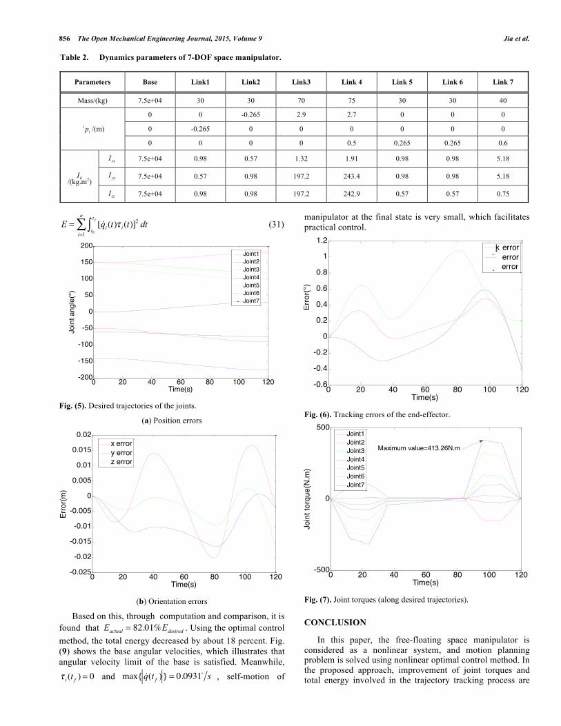
By computing the dynamics equation of the 7-DOF FFSM, the joint torques are obtained when executing desired and actual path, respectively. As shown in Fig. (7), when carrying the heavy payload along the desired path, the maximum value of joint torques is 413.26 N.m. By contrast, maximum torque decreased by about 15 percent when carrying the heavy payload along the actual optimal path (354.73 N.m, as shown in Fig. 8). Besides that, in order to illustrate effectiveness of the proposed algorithm in improving total energy involved during the load-carrying process, the following index is introduced to measure the energy consumption of the space manipulator system [20]:
44.5
55.5
6
66.26.46.66.8
7
7.5
8
Desired PathActual Path
X(m)
Y(m)
Z(m)
856 The Open Mechanical Engineering Journal, 2015, Volume 9 Jia et al.
E = [ !qi(t)! i(t)]
2 dtt0
t f
"i=1
n
# (31)
Fig. (5). Desired trajectories of the joints.
(a) Position errors
(b) Orientation errors
Based on this, through computation and comparison, it is found that Eactual = 82.01%Edesired . Using the optimal control method, the total energy decreased by about 18 percent. Fig. (9) shows the base angular velocities, which illustrates that angular velocity limit of the base is satisfied. Meanwhile,
! i (t f ) = 0 and max{ !q(t f )} = 0.0931
" s , self-motion of
manipulator at the final state is very small, which facilitates practical control.
Fig. (6). Tracking errors of the end-effector.
Fig. (7). Joint torques (along desired trajectories).
CONCLUSION
In this paper, the free-floating space manipulator is considered as a nonlinear system, and motion planning problem is solved using nonlinear optimal control method. In the proposed approach, improvement of joint torques and total energy involved in the trajectory tracking process are
0 20 40 60 80 100 120-200
-150
-100
-50
0
50
100
150
200
Time(s)
Join
t ang
le(°
)
Joint1Joint2Joint3Joint4Joint5Joint6Joint7
0 20 40 60 80 100 120-0.025
-0.02
-0.015
-0.01
-0.005
0
0.005
0.01
0.015
0.02
Time(s)
Erro
r(m)
x errory errorz error
0 20 40 60 80 100 120-0.6
-0.4
-0.2
0
0.2
0.4
0.6
0.8
1
1.2
Time(s)
Erro
r(°)
ķ error error error
0 20 40 60 80 100 120-500
0
500
Time(s)
Join
t tor
que(
N.m
)
Joint1Joint2Joint3Joint4Joint5Joint6Joint7
Maximum value=413.26N.m
Table 2. Dynamics parameters of 7-DOF space manipulator.
Parameters Base Link1 Link2 Link3 Link 4 Link 5 Link 6 Link 7
Mass/(kg) 7.5e+04 30 30 70 75 30 30 40
i pi /(m)
0 0 -0.265 2.9 2.7 0 0 0
0 -0.265 0 0 0 0 0 0
0 0 0 0 0.5 0.265 0.265 0.6
Ik/(kg.m2)
Ixx 7.5e+04 0.98 0.57 1.32 1.91 0.98 0.98 5.18
I yy 7.5e+04 0.57 0.98 197.2 243.4 0.98 0.98 5.18
Izz 7.5e+04 0.98 0.98 197.2 242.9 0.57 0.57 0.75

Motion Planning of Space Manipulator Carrying a Heavy Payload The Open Mechanical Engineering Journal, 2015, Volume 9 857
considered for limitation of load-carrying capacity. In order to track the predefined path in task space and achieve the
Fig. (8). Joint torques (along actual trajectories).
Fig. (9). Angular velocities of the base.
goal of avoiding instability of the base, both tracking accuracy of the end-effector pose and angular velocity control are included in the cost function. SDRE is derived, and optimal control law is obtained by using Taylor series approximation method, which is adopted to overcome the difficulties in obtaining solution of complicated nonlinear system. The optimal motion planning algorithm is finally proposed. In the simulation experiment of a 7-DOF FFSM, maximum value of joint torques and total energy of the system declined by no less than 15%, while the constraints of tracking accuracy and base movement are satisfied. The results demonstrate validity and practicability of the presented algorithm.
CONFLICT OF INTEREST
The authors confirm that this article content has no conflict of interest.
ACKNOWLEDGEMENTS
This work is supported by the National Natural Science Foundation of China (No. 61175080), the National Key Basic Research Program of China (No. 2013CB733000), the Specialized Research Fund for the Doctoral Program of Higher Education (No. 20130005110009).
REFERENCES
[1] A. Flores-Abada, O. Maa, K. Phamb, and S. Ulrich, “A review of space robotics technologies for on-orbit servicing,” Progress in Aerospace Sciences, vol. 68, pp. 1-26, 2014.
[2] E. Coleshill, L. Oshinowo, R. Rembala, B. Bina, D. Rey, and S. Sindelar, “Dextre: ımproving maintenance operations on the International Space Station,” Acta Astronautica, vol. 64, no. 9-10, pp. 869-874, 2009.
[3] Q. Jia, Y. Liu, G. Chen, H. Sun, and J. Peng, “Analysis of load-carrying capacity for redundant free-floating space manipulators in trajectory tracking task,” Mathematical Problems in Engineering, vol. 2014, pp. 1-12, 2014.
[4] L. T. Wang, and B. Ravani, “Dynamic load carrying capacity of mechanical manipulators - part i: problem formulation,” Journal of Dynamic Systems, Measurement and Control, Transactions of the ASME, vol. 110, no. 1, pp. 46-52, 1988.
[5] Z. Chu, J. Cui, and F. Sun, “Fuzzy adaptive disturbance-observer-based robust tracking control of electrically driven free-floating space manipulator,” IEEE Systems Journal, vol. 8, no. 2, pp. 343-352, 2014.
[6] H. Wang, and Y. Xie, “Prediction error based adaptive jacobian tracking for free-floating space manipulators,” IEEE Transactions on Aerospace and Electronic Systems, vol. 48, no. 4, pp. 3207-3221, 2012.
[7] A. Wang, P. Wu, X. Zhou, and X. Pei, “Composite sliding mode control for a free-floating space rigid-flexible coupling manipulator system,” International Journal of Advanced Robotic Systems, vol. 10, pp. 1-9, 2013.
[8] Q. Jia, W. Yao, G. Chen, and H. Sun, "The trajectory tracking of space flexible manipulator with large payloads based on optimal control," Proceedings of the 2013 IEEE 8th Conference on Industrial Electronics and Applications, ICIEA, 2013. pp. 1569-1573.
[9] C.J. Li, “A new method of dynamics for robot manipulators,” Systems, IEEE Transactions on Man and Cybernetics, vol. 18, no. 1, pp. 105-114, 1988.
[10] M. H. Korayem, and A. Nikoobin, “Maximum payload path planning for redundant manipulator using indirect solution of optimal control problem,” International Journal of Advanced Manufacturing Technology, vol. 44, no. 7-8, pp. 725-736, 2009.
[11] M. H. Korayem, E. Davarzani, and M. Bamdad, “Optimal trajectory planning with the dynamic load carrying capacity of a flexible cable-suspended manipulator,” Scientia Iranica Transaction B-Mechanical Engineering, vol. 17, no. 4, pp. 315-326, 2010.
[12] M. H. Korayem, and M. Irani, “Maximum dynamic load determination of mobile manipulators via nonlinear optimal feedback,” Scientia Iranica Transaction B-Mechanical Engineering, vol. 17, no. 2, pp. 121-135, 2010.
[13] W.-F. Xu, Y. Liu, W.-Y. Qiang, B. Liang, and C. Li, “Cartesian continuous-path planning for free-floating space robot,” Kongzhi yu Juece/Control and Decision, vol. 23, no. 3, pp. 278-282+287, 2008.
[14] Y. Liu, Q. Jia, G. Chen, and H. Sun, “Load maximization trajectory optimization for free-floating space robot using multi-objective particle swarm optimization algorithm,” Jiqiren/Robot, vol. 36, no. 4, pp. 402-410, 2014.
[15] M. H. Korayem, A. Zehfroosh, H. Tourajizadeh, and S. Manteghi, “Optimal motion planning of non-linear dynamic systems in the presence of obstacles and moving boundaries using SDRE: application on cable-suspended robot,” Nonlinear Dynamics, vol. 76, no. 2, pp. 1423-1441, 2014.
0 20 40 60 80 100 120-500
0
500
Time(s)
Join
t tor
que(
N.m
)
Joint1Joint2Joint3Joint4Joint5Joint6Joint7
Maximum value=354.73N.m
0 20 40 60 80 100 120-0.8
-0.6
-0.4
-0.2
0
0.2
0.4
0.6
0.8
Time(s)
Angu
lar v
eloc
ity(°
/s)
ķ

858 The Open Mechanical Engineering Journal, 2015, Volume 9 Jia et al.
[16] M. H. Korayem, M. Irani, and S. R. Nekoo, “Analysis of manipulators using SDRE: a closed loop nonlinear optimal control approach,” Scientia Iranica Transaction B-Mechanical Engineering, vol. 17, no. 6, pp. 456-467, Nov-Dec, 2010.
[17] Y. Umetani, and K. Yoshida, “Resolved motion rate control of space manipulators with generalized Jacobian matrix,” IEEE Transactions on Robotics and Automation, vol. 5, no. 3, pp. 303-314, 1989.
[18] H. T. Banks, B. M. Lewis, and H. T. Tran, “Nonlinear feedback controllers and compensators: a state-dependent Riccati equation
approach,” Computational Optimization and Applications, vol. 37, no. 2, pp. 177-218, 2007.
[19] S. C. Beeler, H. T. Tran, and H. T. Banks, “Feedback control methodologies for nonlinear systems,” Journal of Optimization Theory and Applications, vol. 107, no. 1, pp. 1-33, 2000.
[20] G. Field, and Y. Stepanenko, "Iterative dynamic programming: an approach to minimum energy trajectory planning for robotic manipulators," In: Proceedings - IEEE International Conference on Robotics and Automation, pp. 2755-2760, 1996.
Received: February 17, 2014 Revised: March 21, 2015 Accepted: June 9, 2015 © Jia et al.; Licensee Bentham Open This is an open access article licensed under the terms of the (https://creativecommons.org/licenses/by/4.0/legalcode), which permits unrestricted, non-commercial use, distribution and reproduction in any medium, provided the work is properly cited.