starfood 120v - Век Вендинга · starfood 120v doc. no. h 216u 02 edition 3 2004 -01. ......
TRANSCRIPT
INSTALLATION, USE AND MAINTENANCE MANUAL
UK English
StarFood 120V
DOC. NO. H 216U 02
EDITION 3 2004 -01

DICHIARAZIONE DI CONFORMITA’
DECLARATION OF CONFORMITY
DÉCLARATION DE CONFORMITÉ
KONFORMITÄTSERKLÄRUNG
DECLARACIÓN DE CONFORMIDAD
DECLARAÇÃO DE CONFORMIDADE
VERKLARING VAN OVEREENSTEMMING
INTYG OM ÖVERENSSTÄMMELSE
OVERENSSTEMMELSESERKLÆRING
YHDENMUKAISUUSTODISTUS
Dichiara che la macchina descritta nella targhetta di identificazione, è conforme alle disposizioni legislative delle direttive:89/392, 89/336, 73/23 CEE e successive modifiche ed integrazioni.
Declares that the machine described in the identification plate conforms to the legislative directions of the directives: 89/392, 89/336, 73/23 EEC and further amendments and integrations.
Déclare que l’appareil décrit dans la plaque signalétique satisfait aux prescriptions des directives: 89/392, 89/336, 73/23 CEE et modifications/intégrations suivantes.
Erklärt, daß das im Typenschild beschriebene Gerät den EWG Richtlinien 89/392,89/336, 73/23 sowie den folgenden Änderungen/Ergänzungen entspricht.
Declara que la máquina descripta en la placa de identificación, resulta conforme a las disposiciones legislativas de lasdirectivas: 89/392, 89/336, 73/23 CEE y modificaciones y integraciones sucesivas.
Declara que o distribuidor descrita na chapa de identificação é conforme às disposições legislativas das directivas CEE89/392, 89/336 e 73/23 e sucessivas modificações e integrações.
Verklaart dat de op de identificatieplaat beschreven machine overeenstemt met de bepalingen van de EEG richtlijnen89/392, 89/336 en 73/23 en de daaropvolgende wijzigingen en aanvullingen.
Intygar att maskinen som beskrivs på identifieringsskylten överensstämmer med lagstiftningsföreskrifterna i direktiven:89/392, 89/336, 73/23 CEE och påföljande och kompletteringar.
Det erklæres herved, at automaten angivet på typeskiltet er i overensstemmelse med direktiverne89/392, 89/336 og 73/23 EU og de senere ændringer og tillæg.
Forsikrer under eget ansvar at apparatet som beskrives i identifikasjonsplaten, er i overensstemmelse med vilkårene iEU-direktivene 89/392, 89/336, 73/23 med endringer.
Vahvistaa, että arvokyltissä kuvattu laite vastaa EU-direktiivien 89/392, 89/336, 73/23 sekä niihin myöhemmin tehtyjenmuutosten määräyksiä.
Valbrembo, 03/05/2001
ANTONIO CAVO
C.E.O

1© by NECTA VENDING SOLUTIONS SpA 0401 216 - 02
TABLE OF CONTENTS
INTRODUCTION PAGE 2IDENTIFICATION OF THE VENDING MACHINE PAGE 2
IN THE EVENT OF FAILURES PAGE 2
TRANSPORT AND STORAGE PAGE 2
USING THE VENDING MACHINE PAGE 2
POSITIONING THE VENDING MACHINE PAGE 3
WARNING FOR INSTALLATION PAGE 3
PRECAUTIONS IN USING THE MACHINE PAGE 3
WARNING FOR SCRAPPING PAGE 3
TECHNICAL SPECIFICATIONS PAGE 4POWER CONSUMPTION PAGE 4
MAIN FEATURES PAGE 4
LOADING AND CLEANING PAGE 5VENDING SYSTEMS PAGE 5
DISPENSING CYCLE PAGE 5
WARNING FOR LOADING PAGE 5
CONTROLS AND INFORMATION PAGE 5INTERNAL COMPONENTS PAGE 6
LOADING SWITCH PAGE 6
PROGRAMMING SWITCH PAGE 6
HYGIENE AND CLEANING PAGE 7
LOADING PRODUCTS PAGE 7
ROUTINE MAINTENANCE PAGE 8
PERIODICAL CLEANING PAGE 8
SUSPENDING FROM USE PAGE 8
INSTALLATION PAGE 9UNPACKING THE VENDING MACHINE PAGE 9
CONNECTION TO THE POWER SUPPLY PAGE 9
INSTALLING THE PAYMENT SYSTEM PAGE 9
OPERATING MODES PAGE 10USER INTERFACE PAGE 10
NORMAL OPERATING MODE PAGE 10
LOADING PAGE 11
AUTO-CONFIGURATION PAGE 11
FILLER MENU PAGE 12STATISTICS PAGE 12
SELECTION PRICES PAGE 12
CHANGE TUBES CONTROL PAGE 12
ADJUSTING THE AIRFLOW PAGE 12
ANTI-TAMPERING CHECK PAGE 13
TEST PAGE 13
EVADTS TRANSFER PAGE 13
TECHNICIAN MENU PAGE 14PRESENT FAILURES PAGE 14
PROGRAMMING THE PARAMETERS PAGE 15
CASH PAGE 15
COIN MECHANISMS PAGE 15
COMMON FUNCTIONS PAGE 17
DRUMS / SLIDERS PAGE 17
COLD PARAMETERS PAGE 18
DISPLAY PAGE 18
MISCELLANEOUS PAGE 19
PASSWORD PAGE 19
ENERGY SAVING PAGE 19
DISPLAYING THE FILLER MENU PAGE 19
STATISTICS PAGE 19
TEST PAGE 21
SLIDER TEST PAGE 21
COMPLETE SELECTIONS PAGE 21
MISCELLANEOUS PAGE 21
MACHINE INFORMATION PAGE 21
INITIALISING PAGE 21
GSM PAGE 22
EVADTS CODES PAGE 22
MAINTENANCE PAGE 23
PRINTED BOARD FUNCTIONSAND INDICATOR LAMPS PAGE 23
CPU BOARD PAGE 23
ACTUATION BOARD PAGE 24
CONFIGURING THE C.P.U. BOARD PAGE 24
SOFTWARE UPDATE PAGE 24
SELF-DIAGNOSIS FUNCTION PAGE 25
DRUM MAINTENANCE PAGE 26ASSEMBLY OF THE PRODUCT DRUMS PAGE 26
CHANGING THE COMPARTMENTS OF A DRUM PAGE 26
DISASSEMBLING THE DRUM STACK PAGE 27
COOLING SYSTEM PAGE 28
AUTOMATIC DEFROSTING DEVICE PAGE 28
MAINTENANCE AND CLEANING PAGE 28
POWER SUPPLY UNIT PAGE 28
PROGRAMMING MENU - SUMMARY PAGE 29WIRING DIAGRAM PAGE 54

2© by NECTA VENDING SOLUTIONS SpA 0401 216 - 02
IN THE EVENT OF FAILURES
In most cases, any technical problems are corrected bysmall repair operations; however, before contacting themanufacturer we recommend that this manual be readcarefully.Should there be serious failures or malfunctions, thencontact the following:
NECTA VENDING SOLUTIONS SpAVia Roma 2424030 ValbremboItaly - Tel. +39 035606111
TRANSPORT AND STORAGE
To prevent any damage, special care should be takenwhen loading or unloading the vending machine.The machine can be lifted by a motor-driven or manualforklift truck, and the forks are to be placed underneath themachine from the side clearly indicated by the symbol onthe cardboard package.
Do not:
- overturn the vending machine;
- drag the vending machine with ropes or similar;
- lift the vending machine by its sides;
- lift the vending machine with slings or ropes;
- shake or jolt the vending machine and its packing.
The machine should be stored in a dry room where thetemperature remains between 0°C and 40°C.Avoid stacking machines one on top of the other andalways keep it upright as indicated by the arrows on thepacking.
USING THE VENDING MACHINE FORHERMETICALLY SEALED PRODUCTS
A different sale price can be set for each product selectionby the machine electronic control. The various functionsare programmed through the selection buttons without anyneed for additional equipment.All models are fitted with variable configuration drums,permitting the number of partitions to be either increasedor reduced to adapt the machine to the size of the productsto be dispensed, thus optimising the machine capacity.
INTRODUCTION
This technical documentation is part and parcel of thevending machine and must always follow the machinein case it is moved or transfer of ownership, so as toallow consultation by different operators.
Before starting installation and using the machine, it is firstnecessary to carefully read and understand the instruc-tions contained in this manual, as they offer importantinformation on installation safety, operating instructionsand maintenance.
This manual is divided into three chapters.The first chapter describes the loading and routine main-tenance operations which are carried out in areas of themachine accessible with simple use of the door key,without using any other tools.The second chapter contains the instructions for correctinstallation and all information necessary for optimum useof the machine.The third chapter describes maintenance operationswhich involve the use of tools to access potentially danger-ous areas.
The operations described in the second and thirdchapters must be carried out only by personnel whohave the specific knowledge of the machine function-ing from a point of view of electrical safety and healthregulations.
IDENTIFICATION OF THE VENDINGMACHINE AND ITS CHARACTERISTICS
Each machine is identified by its own serial number,indicated on the rating plate attached inside the cabinet onthe right side.This plate is the only one acknowledged by the manufac-turer as identification of the machine, and carries all datawhich readily and safely gives technical information sup-plied by the manufacturer. It also assists in the spare partsmanagement.
Absorbed power
Operating voltage
Type
Current
Frequency
Serial number
Model
Product code
Refrigeration system class Type and amountof refrigerant
3© by NECTA VENDING SOLUTIONS SpA 0401 216 - 02
The vending machine is suitable for dispensing foodthat is hermetically sealed and kept refrigerated.
Strictly comply with the producer’s specificationsregarding storage temperature and expiry date foreach product.
Any other use is unsuitable and thus potentially dan-gerous.
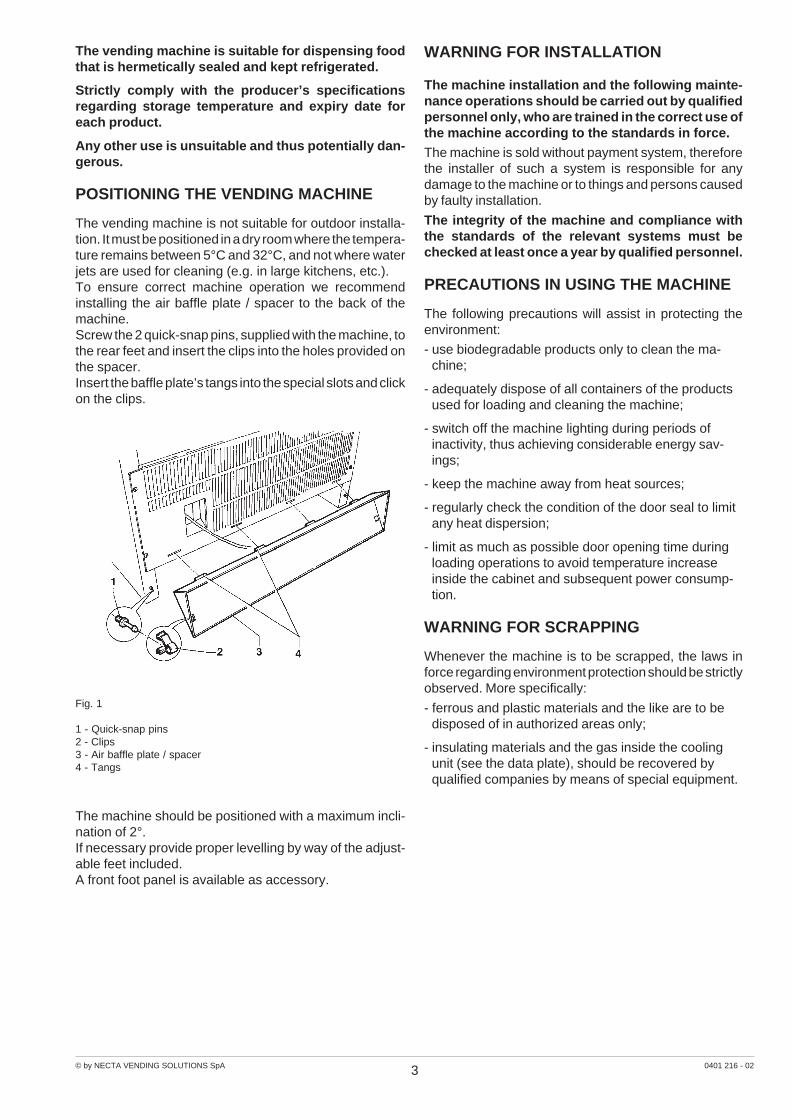
POSITIONING THE VENDING MACHINE
The vending machine is not suitable for outdoor installa-tion. It must be positioned in a dry room where the tempera-ture remains between 5°C and 32°C, and not where waterjets are used for cleaning (e.g. in large kitchens, etc.).To ensure correct machine operation we recommendinstalling the air baffle plate / spacer to the back of themachine.Screw the 2 quick-snap pins, supplied with the machine, tothe rear feet and insert the clips into the holes provided onthe spacer.Insert the baffle plate’s tangs into the special slots and clickon the clips.
WARNING FOR INSTALLATION
The machine installation and the following mainte-nance operations should be carried out by qualifiedpersonnel only, who are trained in the correct use ofthe machine according to the standards in force.The machine is sold without payment system, thereforethe installer of such a system is responsible for anydamage to the machine or to things and persons causedby faulty installation.
The integrity of the machine and compliance withthe standards of the relevant systems must bechecked at least once a year by qualified personnel.
PRECAUTIONS IN USING THE MACHINE
The following precautions will assist in protecting theenvironment:
- use biodegradable products only to clean the ma-chine;
- adequately dispose of all containers of the productsused for loading and cleaning the machine;
- switch off the machine lighting during periods ofinactivity, thus achieving considerable energy sav-ings;
- keep the machine away from heat sources;
- regularly check the condition of the door seal to limitany heat dispersion;
- limit as much as possible door opening time duringloading operations to avoid temperature increaseinside the cabinet and subsequent power consump-tion.
WARNING FOR SCRAPPING
Whenever the machine is to be scrapped, the laws inforce regarding environment protection should be strictlyobserved. More specifically:
- ferrous and plastic materials and the like are to bedisposed of in authorized areas only;
- insulating materials and the gas inside the coolingunit (see the data plate), should be recovered byqualified companies by means of special equipment.
Fig. 1
1 - Quick-snap pins2 - Clips3 - Air baffle plate / spacer4 - Tangs
The machine should be positioned with a maximum incli-nation of 2°.If necessary provide proper levelling by way of the adjust-able feet included.A front foot panel is available as accessory.

4© by NECTA VENDING SOLUTIONS SpA 0401 216 - 02
TECHNICAL SPECIFICATIONS
Power supply voltage 120 V~
Power supply frequency 60 Hz
Max absorbed power 1400 W
Lighting lamps 2x 36 W
DIMENSIONS
Height (A) 1830 mm
Width (B) 850 mm
Depth (C) 895 mm
Overall depth (D) 1650 mm
Weight (with packing) 359 Kg
PAYMENT SYSTEM
The machine is supplied with all electrical prearrangementfor systems with Executive, BDV and MDB protocol, aswell as for installation of 24 V DC validators.Beside the coin mechanism housing, suitable space isprovided for the installation (optional) of the most widelyused payment systems.
SALES PRICESFor each single selection, a different price can be set in 4time bands, programmable for each day of the week;the standard setting has the same price for all selections,without using time bands.
COIN BOX
Cover and lock are available as an optional feature.
POWER CONSUMPTION
The machine power consumption depends on many fac-tors, such as temperature and ventilation of the roomwhere it is installed, temperature of loaded products,internal temperature of the refrigerated box.Under average conditions, and namely:
- Ambient temperature: 20° C
- Refrigerated box temperature: 3° C
- temperature of loaded products(machine completely empty) 5° C
the following power consumption levels resulted:
- to reach operating temperature 12,460 Wh
- Hourly stand-by power consumption 505 Wh
The above power consumption calculated from averagedata should only be taken as an indication.
PERFORMANCE
The machine has been designed to dispense productswhich are very different from each other; therefore alldrums are modular and can be configured with variouscombinations to satisfy many different needs.
- Each drum can be subdivided into 6, 12, 18, 24 or 36sectors.
- Microprocessor control.
- Coin mechanisms or electronic payment systems withinterface for the most widely used communicationprotocols can be installed (Executive, BDV, MDB),alternatively, parallel-type validators can be used.
- Liquid Crystal Display, for messages to the user andfor programming functions.
- Liquid Crystal Display for each drum to indicate thesales price.
- Cooling unit with electronic temperature control.
Fig. 2
REFRIGERATING SYSTEM
Operating conditions:
Max temperature: 32° C, max relative humidity: 75%
Compressor: 18 cm3
Kg 0.4 of R134a refrigerant
Fan-forced evaporator
Programmable defrosting cycle
5© by NECTA VENDING SOLUTIONS SpA 0401 216 - 02
Chapter 1LOADING AND CLEANING
VENDING SYSTEMS
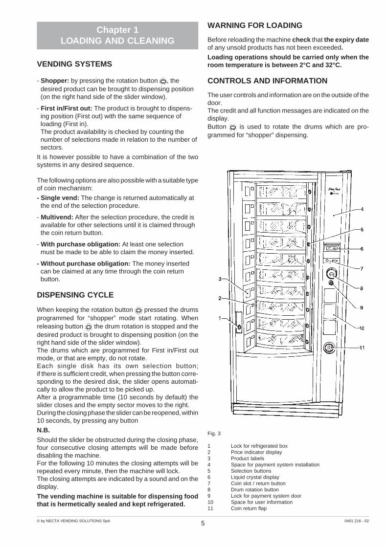
- Shopper: by pressing the rotation button , thedesired product can be brought to dispensing position(on the right hand side of the slider window).
- First in/First out: The product is brought to dispens-ing position (First out) with the same sequence ofloading (First in).The product availability is checked by counting thenumber of selections made in relation to the number ofsectors.
It is however possible to have a combination of the twosystems in any desired sequence.
The following options are also possible with a suitable typeof coin mechanism:
- Single vend: The change is returned automatically atthe end of the selection procedure.
- Multivend: After the selection procedure, the credit isavailable for other selections until it is claimed throughthe coin return button.
- With purchase obligation: At least one selectionmust be made to be able to claim the money inserted.
- Without purchase obligation: The money insertedcan be claimed at any time through the coin returnbutton.
DISPENSING CYCLE
When keeping the rotation button pressed the drumsprogrammed for “shopper” mode start rotating. Whenreleasing button the drum rotation is stopped and thedesired product is brought to dispensing position (on theright hand side of the slider window).The drums which are programmed for First in/First outmode, or that are empty, do not rotate.Each single disk has its own selection button;if there is sufficient credit, when pressing the button corre-sponding to the desired disk, the slider opens automati-cally to allow the product to be picked up.After a programmable time (10 seconds by default) theslider closes and the empty sector moves to the right.During the closing phase the slider can be reopened, within10 seconds, by pressing any button
N.B.
Should the slider be obstructed during the closing phase,four consecutive closing attempts will be made beforedisabling the machine.For the following 10 minutes the closing attempts will berepeated every minute, then the machine will lock.The closing attempts are indicated by a sound and on thedisplay.
The vending machine is suitable for dispensing foodthat is hermetically sealed and kept refrigerated.
WARNING FOR LOADING
Before reloading the machine check that the expiry dateof any unsold products has not been exceeded.
Loading operations should be carried only when theroom temperature is between 2°C and 32°C.
CONTROLS AND INFORMATION
The user controls and information are on the outside of thedoor.The credit and all function messages are indicated on thedisplay.Button is used to rotate the drums which are pro-grammed for “shopper” dispensing.
Fig. 3
1 Lock for refrigerated box2 Price indicator display3 Product labels4 Space for payment system installation5 Selection buttons6 Liquid crystal display7 Coin slot / return button8 Drum rotation button9 Lock for payment system door10 Space for user information11 Coin return flap

6© by NECTA VENDING SOLUTIONS SpA 0401 216 - 02
INTERNAL COMPONENTS
The cooling unit positioned in the lower section of thecabinet ensures correct product temperature.The evaporator is defrosted automatically every 6 hours byreversing the gas flow. The timing can however be pro-grammed between 1 and 99 hours.The C.P.U. (central processing unit) board, accessed fromthe payment system compartment, and the power board,located on the door, control the different functions of thevending machine.The power supply unit, located in the lower section of thecabinet, contains the protection fuses and the main switch.
Fig. 4
1 Cooling unit2 Power supply unit3 Actuation board4 Loading switch5 Slider motors6 Slider opening microswitch7 Slider guide assemblies8 Loading buttons
PROGRAMMING SWITCH
When opening the payment system compartment door theprogramming switch is triggered.The message “Loading” is indicated on the display and theselection buttons are assigned programming functions.This allows programming and/or loading operations to becarried out with the refrigerated box door closed.The vending cycle is disabled.
IMPORTANT NOTICE!!
The loading and programming switches DO NOT dis-connect the power supply from the machine.
To switch the machine off the main switch must beused and the plug must be pulled out.
All operations which require the machine to be ener-gised and the protective casings removed must becarried out by qualified personnel, informed about thespecific risks of such condition.
LOADING SWITCH
The loading microswitch is fitted on the lower right-handside of the door.When the door is open, the drum rotation buttons areenabled for loading.The message “Loading with the door open” is indicated onthe display and dispensing is disabled.
Fig. 5
1 CPU board2 RS 232 serial port3 Programming access button4 Failure reset button5 Programming switch6 Liquid crystal display7 Coin chute8 Coin return lever

7© by NECTA VENDING SOLUTIONS SpA 0401 216 - 02
HYGIENE AND CLEANING
According to current health and safety regulations, thevending machine operator is responsible for its hygieneand maintenance.It is advisable to use sanitising products (chlorine baseddetergent or similar) to clean all surfaces even if not indirect contact with food.Some parts of the machine can be damaged by strongdetergents.
Do not use any soaked cloth to clean motors, lightinglamps, loading buttons or the front cover of the powersupply unit (see Fig. 4).The manufacturer declines all responsibility for damagecaused by noncompliance with the above instructions or bythe use of strong or toxic chemical agents.
Under no circumstances should sprayed water beused.
Always disconnect the machine from the power sup-ply grid before any cleaning operations.
The integrity of the machine and compliance with thestandards of the relevant systems must be checked atleast once a year by qualified personnel.
LOADING PRODUCTS
Important notice!!!
Products must be hermetically sealed.
When starting the machine for the first time, before loadingthe refrigerated products it is necessary to switch thepower on and then wait until the normal operating tempera-ture is reached (up to 3 hours of pull-down time).
Before loading, it is necessary to check that the inter-nal temperature of the machine is lower than 5°C.
Before refilling the machine check that the expiry date ofany unsold products has not been exceeded.The machine control system allows storage of the numberof days to the expiry date for each disk sector; and after thisis exceeded the sector is considered empty and thereforethe product not to be sold.When opening the front or rear door (on models where it isfitted), the relevant loading buttons are enabled.Pressing one of loading buttons will cause the correspond-ing drum to rotate, bringing each sector into loading posi-tion.
The drum will be considered completely full and thecounting of days to the expiry date for the sectors ofthat drum will be reset.
Special attention must be paid to the dispensing modesetting for the drum being loaded, if programmed for“shopper” it will be possible to leave some sectors empty,if programmed for F.I.F.O. it will be necessary to fill allsectors.
For loading, the instructions indicated on the inside of thedoor must be followed, particularly ensuring that:
- no items of refrigerated food with a temperatureabove 5°C are inserted, and that all spaces are filled;
- the bottom of the products rest at the bottom of thecompartment with the label facing the window so thatthey can be identified;
- the product packaging does not interfere with thepartition counter lever.
LOADING WITH THE DOOR CLOSED
If only few products are to be loaded, it might be convenientto insert them into the machine through the dispensingsliders without opening the door, thus ensuring that theproducts already in the machine stay cold.By opening the payment system compartment door, themachine goes into manual loading mode and the numberof empty sectors, or with expired products, for each drumis indicated on the price display.When pressing the selection button, the first empty/ex-pired sector is presented and the slider opens so that theproduct can be inserted.Then, when pressing the selection button again, the nextsector is presented for filling or the slider closes if the drumis full.Loading operations for a drum can be interrupted bypressing the button of another selection.
All loading operations must however be carried out asquickly as possible, to avoid that the temperature ofproducts exceeds the safety temperature.
NOISE LEVEL
The continuous, weighted equivalent acoustic pressurelevel is below 70 dB.
Fig. 6
1 Partitions2 Partition counting lever
8© by NECTA VENDING SOLUTIONS SpA 0401 216 - 02
ROUTINE MAINTENANCE
Before carrying out any cleaning or maintenance opera-tions, disconnect the machine from the mains powersupply.
Under no circumstances should sprayed water beused to wash the machine.
PERIODICAL CLEANING
Clean metal parts with lukewarm water and mild detergent,then rinse thoroughly and wipe dry carefully.
When cleaning metal parts do not use detergentscontaining abrasive or corrosive agents; do not usecommon steel wool, wire brushes or steel scrapers.
Switch off the machine in the event of failure ormalfunction. Any repairs should be carried out exclu-sively by qualified personnel using original spareparts only.
SUSPENDING FROM USE
For long periods of inactivity the following recommenda-tions should be observed:
- disconnect the plug from the power outlet;
- remove all products from the drums and clean theinside and all accessories;
- using a cloth lightly damp with Vaseline oil, apply aprotective film on all metal surfaces.
9© by NECTA VENDING SOLUTIONS SpA 0401 216 - 02
Chapter 2INSTALLATION
Installation and the following maintenance operationsshould be carried out with the machine switched on andtherefore by qualified personnel only, who are trained in thecorrect use of the machine and informed about the specificrisks of such situation.
The machine is not suitable for outdoor installation, itmust be installed in a dry room where the temperatureremains between 5°C and 32°C.
It cannot be positioned where water jets are used forcleaning (e.g. in large kitchens, etc.).
The machine should be positioned with a maximuminclination of 2°.
UNPACKING THE VENDING MACHINE
After removing the packing, ensure that the machine isintact.If the vending machine is found to be damaged, immedi-ately inform the carrier and do not use the machine.
No packing elements (i.e. plastic bags, polystyrenefoam, nails, etc.) should be left within the reach ofchildren, as they are potentially dangerous.
Packing materials must be disposed of in authorisedcontainers and the recyclable ones must be recovered byqualified companies.
CONNECTING THE MACHINE TO THEPOWER SUPPLY
The machine is designed to operate under single-phase120 V~ voltage and is protected by 20 A fuses.Before making the connection, ensure that the ratingcorresponds to that of the power grid, and more specifi-cally:
- the supply voltage rating must be within the rangerecommended for the connection points;
- the main switch should be capable of withstanding thepeak load required, and at the same time ensureproper omnipolar disconnection from the power gridwith an opening gap of the contacts of at least 3 mm.
The switch, the power outlet and the plug must belocated in an easily accessible position.
The electrical safety of the machine is ensured only whenit is correctly earthed according to the safety standards inforce.
This fundamental safety requirement must be dulyverified, and if in doubt the system must be carefullytested by qualified technicians.
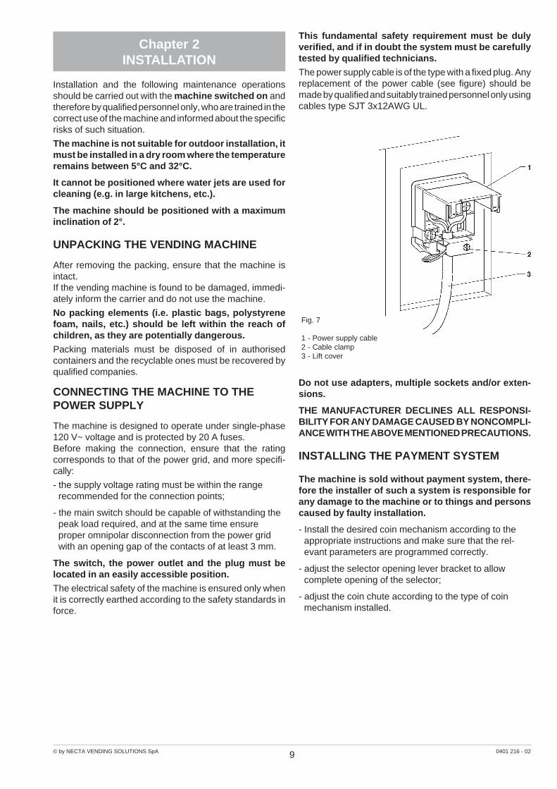
The power supply cable is of the type with a fixed plug. Anyreplacement of the power cable (see figure) should bemade by qualified and suitably trained personnel only usingcables type SJT 3x12AWG UL.
Fig. 7
1 - Power supply cable2 - Cable clamp3 - Lift cover
Do not use adapters, multiple sockets and/or exten-sions.
THE MANUFACTURER DECLINES ALL RESPONSI-BILITY FOR ANY DAMAGE CAUSED BY NONCOMPLI-ANCE WITH THE ABOVE MENTIONED PRECAUTIONS.
INSTALLING THE PAYMENT SYSTEM
The machine is sold without payment system, there-fore the installer of such a system is responsible forany damage to the machine or to things and personscaused by faulty installation.
- Install the desired coin mechanism according to theappropriate instructions and make sure that the rel-evant parameters are programmed correctly.
- adjust the selector opening lever bracket to allowcomplete opening of the selector;
- adjust the coin chute according to the type of coinmechanism installed.

10© by NECTA VENDING SOLUTIONS SpA 0401 216 - 02
OPERATING MODES
The vending machines in this range have four differentfunction levels, and namely:
- normal operation;
- loading;
- filler menu;
- technician menu.
According to the operating mode, the display and keypadfunctions change as described in the following paragraphs.
USER INTERFACE
The interaction between system and user occurs throughthe following components:
- Button , used to rotate those drums that are pro-grammed for “Shopper” mode or, with the door open,all drums.
- Liquid crystal display (LCD) 4 lines of 20 characters.
- The first four selection buttons, which in maintenanceand programming mode have the following functions(see Fig. 8):
Scrolling buttons “ ” and “ ”:
To move to the next or previous menu option.
Confirm button “ ”:
To move from a menu to a sub-menu or it is used to confirmthe current information on the display.
Exit button “ ”:
To move back from a sub-menu to the higher level menu,or used to cancel the current information on the display.
Programming button “ ”:
(See Fig. 5) To move back from a sub-menu requiring theuse of selection buttons to the higher level menu.
NORMAL OPERATING MODE
The machine is preset to “Normal operation” mode whenconnected to the power supply with the door closed (seeprogramming switch).The lighting lamps are switched on and the product dis-pensing messages are indicated on the display, as well asother information like temperature and time or details ofany current failures.When pressing button the drums programmed for“shopper” mode will rotate until the button is released.If there is sufficient credit, when pressing a selection buttonthe corresponding slider, driven by the motor, opens auto-matically to the slider stop.
Fig. 8
Fig. 9
1 - Product slider2 - Rack3 - Slider stop4 - Cog wheel5 - Slider microswitch6 - Motor snap tangs7 - Slider motor
The control system detects the increase in electrical ab-sorption of the motor and stops it for a programmable time(10 seconds by default).After this time lapses, the motor starts closing the slider.During the closing phase the slider can be opened again bypressing a selection button:Should the slider be obstructed in some way, four consecu-tive closing attempts will be made before disabling themachine.For the following 10 minutes the closing attempts will berepeated every 60 seconds.The closing attempts are indicated by a sound and on thedisplay.

11© by NECTA VENDING SOLUTIONS SpA 0401 216 - 02
Each drum is monitored by a device which counts thesectors with sold products, so that the empty drums areidentified, as well as allowing or preventing the rotation bymeans of a magnet.
LOADING
With the door openA special switch (see Fig. 4) signals to the control systemthat the door is open.The loading buttons are activated and product vending isdisabled.When pressing a loading button, the corresponding drumrotates, to allow refilling, until the button is released.As soon as it is operated, the drum is considered com-pletely full and the counter of number of days to the expirydate for that drum is reset.
With the door closed
In order to avoid a temperature increase inside the refrig-erated box, the products can be loaded through the dis-pensing sliders.The machine is preset for loading with the door closed(release of a single slider) by opening the payment systemcompartment door; the number of empty sectors is indi-cated on the price display of each drum.When pressing the selection button, the first empty/ex-pired sector is presented and the slider opens so that theproduct can be inserted.Then, when pressing the selection button again, the nextsector is presented for filling or the slider closes if the drumis full.Loading operations for a disk can be interrupted by press-ing the button of another selection.
AUTO-CONFIGURATION
If the machine is disconnected from the mains powersupply by unplugging the cable or using the main switch(see Fig. 20), when restarting the machine will go throughan auto-configuration cycle.The drums will be rotated at least a full turn, then thenumber of detected compartments for each drum and theposition of the home point magnet will be stored.
Fig. 10
1 - Securing screw2 - Sector counting lever3 - Home point magnet sensor4 - Stop magnet pin5 - Drum monitoring device6 - Anti-rotation lever7 - Quick snap hook
Counting is by means of a lever, operated by the passageof partitions.A sensor detects the passage of a magnet, located on theedge of each drum, identifying the home point.

12© by NECTA VENDING SOLUTIONS SpA 0401 216 - 02
FILLER MENU
The machine is preset to “filler menu” mode when thepayment system compartment door is opened and theprogramming button is pressed (see Fig. 5).The keys “ ” and “ ” scroll through the menu items, whichinclude:
“Statistics” Data reading
“Prices” Changing the price for oneselection
“Tubes control” Manual refill and release ofchange tubes
“Air adjustment” Movement of stack and drumsto align the air flow regulators
“Anti-tampering” Checking if the soldcompartments contain objects
“Test” activating the drums;activating the sliders;test dispensing for each drum.
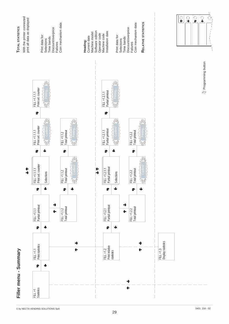
STATISTICS
Data on the machine operations is stored in both generalcounters and relative counters, which can be reset withoutlosing total data.
Connect an RS232 serial printer having a Baud rate of9600, 8 data bit, no parity, 1 stop bit to the serial port locatedon the push button board to print all of the statistics, andnamely:
Total
1 - counter by single selection;
2 - counter by time bands;
3 - failure counter;
4 - coin mechanism data.
Relative
1 - counter by single selection;
2 - counter by time bands;
3 - failure counter;
4 - coin mechanism data.
The printout will also contain the machine code, the dateand the software version.
To connect the printer, do as follows:
- press the confirm print button “ ”, displaying themessage “Confirm?”;
- connect the printer before confirming;
- press the confirm button “ ” to start printing.
DISPLAY
When pressing the confirm button “ ” the data describedin the paragraph “Printing the statistics” is sequentiallydisplayed.
RESET
Statistics can be reset for relative counters globally (alltypes of data) or selectively for:
- selections
- failures
- coin mechanism data
Press the confirm button “ ”, and the message “Confirm?”starts blinking.Press the confirm button “ ”, the message “Working” isdisplayed for a few seconds and all statistics are reset.
SELECTION PRICES
This function is used to change the sales price for allcompartments of a drum, for time band 0 and for all daysof the week.
CHANGE TUBES CONTROL
By accessing the “Tube control” function the change tubescan be filled or released manually.Confirm refilling, and the display will indicate“Credit: ——” which is the value of money available inchange the tubes; insert the desired coin into the selectorand the display will indicate the value of money available inthe change tubes.When confirming releasing, it will be possible to decidewhich tube to release. Each time the confirm button “ ” ispressed, a coin is ejected from the active tube.
ADJUSTING THE AIRFLOW
The cold air flow coming from the central stack can beadjusted for each drum by means of the special adjust-ment screw. In order to make any adjustment the screwsmust be aligned with the corresponding holes on thedrums.With this function the entire stack can be rotated bypressing a loading button, until the screws are positionedin front of the operator.It is also possible to unlock a single drum to be rotatedmanually until the hole is aligned with the adjustmentscrew.

13© by NECTA VENDING SOLUTIONS SpA 0401 216 - 02
ANTI-TAMPERING CHECK
This function is used to align to vending position thecompartments recognised as empty by the machine con-trol software to visually check that no products wereaccidentally left.
TEST
DRUM TEST
With this function the correct functioning of the drumrotation can be tested by pressing the selection buttons.With these function, pressing the loading buttons does notchange the status of a drum and/or of a sector (full/empty/expired).
SLIDER TEST
With this function the correct functioning of the sliders canbe tested by pressing the selection buttons without rotatingthe drums.With these function, pressing the loading buttons does notchange the status of a drum and/or of a sector (full/empty/expired).
COMPLETE SELECTIONSNormal product dispensing can be simulatedwithout inserting any money.With this function, pressing the selection button changesthe status of a drum and/or of a sector (full/empty/expired).
GSM PRE-ALARMS
The control software can send, via GSM modem, a signalindicating an “ending product” signal, when there is only acertain (programmable) number of pieces or grams ofpowder of a given product left. With this function thecounters that control the pre-alarms are reset.
EVADTS TRANSFER
When activating this function, the machine awaits theconnection with a device to acquire the EVADTS statistics.
14© by NECTA VENDING SOLUTIONS SpA 0401 216 - 02
TECHNICIAN MENU
Using the programming procedures described in this sec-tion, it is possible to set all variables regarding machineconfiguration.The machine is preset to “technician menu” mode whenconnected to the power supply with the payment systemdoor open and the programming button is pressed twice.
N.B. When pressing the button again while in theprogramming menu, the machine will return to “load-ing” mode.
The keys “ ” and “ ” scroll through the technician menuitems, which include:
Failures Reading present failuresReading drum/slider failuresDeleteLighting Lamps On/Off
with out of service
Prog. parameters Cash PricesCoin mech.
Decimal pointBonus
Drums/sliders Drumparameters
Sliderparameters
Cold parameters TemperatureDefrostingAir adjustmentCooling unit
Display LanguageUser messagesPromotional
messagePersonal. stringsEuroDisplaycounters
Miscellaneous PasswordEnergy savingProgr. level
Statistics Print PartialTotal
Print relative PartialTotal
Display SelectionsTime bandsFailuresCoin mech.
Display relative SelectionsTime bandsFailuresCoin mech.
Delete PartialTotal
Cancel relative PartialTotal
Test DrumSliderComplete selection
Miscellaneous Machine info Installation dateMachine codeOperator code
Initialising
GSM Pin codePre-alarms
EVADTS Pass codeSecurity codeConnection
PRESENT FAILURES
READINGWhen the “Failure” function is displayed, press the confirmbutton “ ” to display the present failures.If no failures are currently present, after pressing theconfirm button “ ” the message “End failures” will bedisplayed.The monitored failures are:
Compressor
The machine is locked if the compressor runs nonstop formore than 24 hours.
Coin mechanism
The machine is locked if it receives a pulse longer than 2seconds on a validator line or the communication with theserial coin mechanism does not take place for more than30 seconds (Executive protocol) or 75 seconds (BDVprotocol).
RAM Data
One or more areas of the RAM contain wrong data whichwas corrected with the default values.The machine will continue to function, but it would beadvisable to initialise as soon as possible.
Probe
The machine is locked after 5 minutes if the internaltemperature sensor is disconnected; the display will indi-cate a temperature of -11° C.The machine is locked after one hour if a sensor shortcircuit is detected; in this case the display will indicate atemperature of +41° C.
Machine control board
Failed dialogue between C.P.U. board and machine con-trol board.
Gas temperature sensor
The display will indicate the message if a short-circuit isdetected on the temperature control sensor of the hot-gasevaporator.

15© by NECTA VENDING SOLUTIONS SpA 0401 216 - 02
DISPLAYING DRUMS / SLIDERS
Slider failureIf the motor electrical absorption is absent or above theprogrammed threshold, power is disconnected from themotor and the selection is disabled.
Slider open
If the microswitch does not return to normal position within3 attempts of 10 seconds after opening the slider, themachine is set out of service.10 more closing attempts are made at 60 second intervals.
Drum failureIf the “home” point magnet is not detected after a completedrum rotation, or if a microswitch does not detect thepassage of the partition after making a selection, theselection is disabled.
RESET
By confirming this function all current failures will be reset
EXTERNAL LIGHTINGSetting whether or not the lighting lamps in the externalpanels are to be switched on when the machine is out ofservice or during the “Energy saving” time band.
PROGRAMMING THE PARAMETERS
CASH
This set of functions controls all parameters regarding thepayment systems and the sales prices.
SELECTION PRICES
Four different prices can be set for each selection, and foreach day of the week, programmed according to the timebands, if enabled.For each of the 4 time bands prices (0 to 65,535) can beprogrammed globally (same price for all selections) or forthe single selections.Should the majority of products be sold at the same price,it will be convenient to set the price globally and thenchange the figure of the selections with different prices.
TIME BANDSFour programmable time bands are provided for sellingproducts at different prices.The time periods are programmable for beginning and endtime by hours (00 to 23) and minutes (00 to 59).If the values for start and end of the time band are set to00.00 the time period is disabled.The reference time is kept by an internal clock, program-mable as:day/month/year weekday 1-7and thenhour/minutes/seconds.
COIN MECHANISMS
It is possible to decide which of the payment systemprotocols available are to be enabled for the functions.The available payment systems are:
- Executive
- Validators
- BDV
- MDB
By selecting one of the systems it is possible to control itsfunctions.
EXECUTIVEThe following payments systems are available for theExecutive system:
- Standard
- Price Holding
- Coges
- U-Key
VALIDATORS
When the “Validat. Lines” (line setting) function of the“technician” menu is displayed, the value of the 6 validatorcoin lines, A to F, can be changed.
BDVThe BDV protocol menus are used for defining the follow-ing functions:
Type of vending
Setting the operating mode for multiple or single dispens-ing. With multiple dispensing, the change is not automati-cally returned after a successful selection, however thecredit is available for further selections. When pressing thecoin return button, the available credit is returned if its valueis lower than the maximum change value.
Change controlThis function enables/disables the return of credit if noselections are made.If enabled, this function allows the return of coins even if thefirst selection was not dispensed.If however a selection fails for any reason, the change willbe returned if requested.Maximum creditThis function is used to define the maximum acceptedcredit.Maximum changeIt is possible to set a limit to the total amount of changereturned by the coin mechanism when pressing the coinreturn button or after a single dispensing serving.Any credit exceeding the amount programmed with thisfunction will be cashed.
Accepted coins
It is possible to define which, among the coins recognisedby the validator, are to be accepted.Check the label on the coin mechanism for the correct cointo value matching, indicating the position of the coins.

16© by NECTA VENDING SOLUTIONS SpA 0401 216 - 02
Not accepted coins
This function programs the rejection of coins when in“exact amount” mode.Check the label on the coin mechanism for the correct cointo value matching, indicating the position of the coins.
Dispensing buttonsThis function enables or not the buttons on the coinmechanism used to release the coins in the change returntubes.
Value of “exact amount”
This value defines the combination of empty coin tubes,setting the coin mechanism in “exact amount” mode. Thepossible combinations of empty coin tubes are indicatedbelow.For greater simplicity, the combination is described withreference to tubes A, B and C, where tube A receives thelower value coins and tube C the greater value coins.
0 = A or (B and C)1 = A and B and C2 = A and B only3 = A and (B or C)4 = A only5 = A or B (default) only6 = A or B or C7 = A or B only8 = A or C only9 = B and C only10 = B only11 = B or C only12 = C only
C.P.C. deviceIt dialogues with the coin mechanism if devices are in-stalled or removed from the serial interface (C.P.C.-typedevices - the monitoring unit is always enabled by default).
Minimum level of tubes
It brings forward the “Insert exact amount” message for theuser, by adding a number of coins between 0 and 15 to theprogrammed number of coins, to set the “full changetubes” status.
Free Vend VMCMost payment systems with the BDV protocol control thefree vend function.However, there are some payment systems without suchfunction.In this case, if free selections are to be dispensed, freevending must be enabled with VMC (vending machinecontrol, enabled by default) and the price of the selectionsmust be set to zero.
MDB
The MDB protocol menus are used for defining the follow-ing functions:
Type of vendingSetting the operating mode for multiple or single dispens-ing. With multiple dispensing, the change is not automati-cally returned after a successful selection, however thecredit is available for further selections. When pressing thecoin return button (if the function is enabled), the availablecredit is returned up to the maximum change value.
Change control
To enable/disable the operation of the coin return button.Maximum creditThis function is used to define the maximum acceptedcredit.Maximum changeIt is possible to set a limit to the total amount of changereturned by the coin mechanism when pressing the coinreturn button or after a single dispensing serving.Any credit exceeding the amount programmed with thisfunction will be cashed.
Accepted coinsIt is possible to define which, among the coins recognisedby the validator, are to be accepted when the change tubesare full.Check the coin mechanism configuration for the correctcoin to value matching.
Returned coins
It is possible to define which, among the coins available inthe tubes, are to be used for returning the change. Thisparameter is active only with coin mechanisms that do notautomatically control the choice of tube to be used (Autochanger payout).Check the coin mechanism configuration for the correctcoin to value matching.
Accepted billsIt is possible to define which, among the bills recognised bythe reader, are to be accepted.Check the reader configuration for the correct bill to valuematching.
Minimum level of tubes
This function is used for setting the number of coins (0 to15) to determine the status of full change tubes and the“Insert exact amount” message for the user.
Accepted coins with “exact amount”It is possible to define which, among the coins recognisedby the validator, are to be accepted when the machine is inthe “exact amount” condition.Check the coin mechanism configuration for the correctcoin to value matching.

17© by NECTA VENDING SOLUTIONS SpA 0401 216 - 02
COMMON FUNCTIONS
Other menus are available, common to the three protocols,used for defining the following functions:
IMMEDIATE CHANGE
Normally, the amount of credit inserted for a selection iscashed after the machine sends the message “Selectionsuccessful”.When this function is enabled, disabled by default, thecash message is sent at the beginning of dispensing.
DECIMAL POINTPress the confirm button “ ” to display the position of thedecimal point, i.e.:
0 decimal point disabled
1 XXX.X
2 XX.XX
3 X.XXX
Press the confirm button “ ”, these values will start blinkingand can then be modified as necessary.
FREE VEND BONUS
This function, compatibly with the national laws, permitsthe dispensing of a free product every certain programma-ble number of sold selections. In any case the free selec-tion is random within the programmed number. The ma-chine emits an intermittent sound signal and the displayindicates a congratulations message.
DRUMS / SLIDERS
This set of functions is used to define the control param-eters of the different drums and sliders.
DRUM VENDING PARAMETERS
The programmable drum parameters are as follows:
Type of vending
Setting the vending mode (Shopper or First In - First Out)for each drum;
Drum statusEnabling or disabling a drum for vending
Drum status by time band
Enabling or disabling a drum for vending according to theprogrammed time bands.
Drum expiry dateSetting the number of days from the last refill after whichthe sectors are considered expired (vending disabled).The counter is reset for all sectors of a drum at each refill.With the number of days to expiry date set to zero (default)this function is disabled.
Drum rotation
Setting the amount of time between the slider closing andthe moment when the drum rotation can start.During this time the slider can be reopened.
Drum codesA four-digit code can be assigned to each drum, identifyingthe drum when processing the statistical data.
SLIDER PARAMETERS
Slider opening timeSetting the amount of time for slider opening (10 sec. bydefault).
18© by NECTA VENDING SOLUTIONS SpA 0401 216 - 02
COLD PARAMETERS
The operation of the refrigeration system can be pro-grammed for the following functions.
TEMPERATURE
Internal temperature
The internal temperature of the machine during normaloperation can be set directly in °C (3 to 25); the defaultsetting is 3° C.
Safety temperatureThis function enables the control over the temperature (4°C higher than the rated internal temperature) to be reachedwithin 45 minutes from switching the machine on, fromclosing the door or after 15 minutes of normal operation.When this function is active, if the temperature is notreached the machine is locked.
Temperature log
The internal temperature is stored every 10 minutes.With this function, it is possible to read the date, time andstored temperature.
DEFROSTING
Automatic defrosting (with hot gas)
This function allows for a defrosting cycle (flow of hot gasto the evaporator) of 10 minutes maximum. The timeinterval between cycles can be programmed from 0 to 99hours (the default setting is 6 hours); the time interval willbe determined according to the relative ambient humidityand to the frequency of door openings.With the timing set to 0 the function is disabled.
Defrosting cycle logThe duration in minutes of every defrosting cycle is stored.With this function, it is possible to read the date, time andstored duration.
ADJUSTING THE AIRFLOW
The cold air flow coming from the central stack can beadjusted for each drum by means of the special adjust-ment screw. In order to make any adjustment the screwsmust be aligned with the corresponding holes on thedrums.With this function the entire stack can be rotated bypressing a loading button, until the screws are positionedin front of the operator.It is also possible to unlock a single drum to be rotatedmanually until the hole is aligned with the adjustmentscrew.
ENABLE COLD UNITThe cooling unit operation can be disabled. The changewill apply when restarting the machine.
DISPLAY
This set of functions is used to manage the messagesindicated on the external display.
LANGUAGE
There is a choice of language, selected among the onesincluded in the EPROM, to be used for the messages onthe display.
DISPLAYING MESSAGES FOR THE USERIt is possible to choose the kind of information to beindicated on the display during normal operation.The following information can be displayed:
- No information
- Internal temperature
- Date and time
It is possible to choose the language for the displayedmessages.
PROMOTIONAL MESSAGE
Enable
When in this menu, press the confirm button “ ” to displaythe status of the message (enabled or disabled). Thestatus can then be changed using the “ ” and “ ” buttons.
SettingThe 4-line message can be written using the “ ” and “ ”buttons to scroll through the available characters.Press the confirm button “ ”, the first character will startblinking and can be modified.The message is stored by pressing button “ ”.
PERSONALISING THE MESSAGES
The machine uses standard messages to give informa-tion to the user during normal operation (e.g. “Ready”,“Take” etc.). When this function is enabled, the messagecan be changed in the same manner as setting thepromotional message. Changes are stored as copies ofthe standard messages.Therefore, if this function is disabled, the standard mes-sages will be displayed again, but the changed messagesare still stored.
EUROIt is possible to decide whether the selection prices are tobe displayed in Euro, the local currency or both.
DISPLAY THE SELECTION COUNTERS
This function is used to enable/disable the display of thetotal number of sales since the last statistic reset, duringthe start-up phase of the machine.
19© by NECTA VENDING SOLUTIONS SpA 0401 216 - 02
MISCELLANEOUS
This set of functions contains some sub-menus, used lessfrequently, which permit control of the functions describedbelow.
PASSWORD
Entering the passwordIt is a 5-digit numeric code which is required to accessprogramming.The default value of this code is set to 00000.
Enabling the password
This function is used to enable the option of requesting thepassword to access programming; the password requestis disabled by default.
ENERGY SAVING
In order to save electric energy when the machine is notin use, this function is used to switch off the externallighting.2 switch-off time bands can be programmed on a weeklybasis; the week days are identified by a progressivenumber (1=Monday, 2=Tuesday etc.).The same time band cannot include days from differentweeks.If time bands are set overlapping, the machine will remainswitched on for the shorter period.For example, in order to set energy saving time bands torun the vending machine from 07.00 to 22.00 during theweek and leave it switched off on the weekend, the timebands should be set, using the special menu, as indicatedin the table below.
STATISTICS
Data on the machine operations is stored in both generalcounters and relative counters, which can be reset withoutlosing total data.
Connect an RS232 serial printer having a Baud rate of9600, 8 data bit, no parity, 1 stop bit to the serial portlocated on the push button board to print all of thestatistics, and namely:
Total1 - counter by single selection;2 - counter by time bands;3 - failure counter;4 - coin mechanism data;
Relative
1 - counter by single selection;2 - counter by time bands;3 - failure counter;4 - coin mechanism data;The hardcopy printout will also contain the machine infor-mation, and namely:- date/time of print- machine name- software version- operator code- machine code- Installation date.To connect the printer, do as follows:
- press the confirm print button “ ”, displaying themessage “Confirm?”;
- connect the printer before confirming;
- press the confirm button “ ” to start printing.
DISPLAY
When pressing the confirm button “ ” the data describedin the paragraph “Printing the statistics” is sequentiallydisplayed.
RESETTING THE STATISTICSStatistics can be reset for counters globally (all types ofdata) or selectively for:
Total
- selections- failures- coin mechanism data
Relative- selections- failures- coin mechanism dataPress the confirm button “ ”, and the message “Con-firm?” starts blinking.Press the confirm button “ ”, the message “Working” isdisplayed for a few seconds and all statistics are reset.N.B.: when resetting the total statistics also the relativestatistics are reset.
DISPLAYING THE FILLER MENU
This function is used to determine the filler menu optionsto be left active or to be disabled.The reference numbers of the menus do not change evenif some are disabled.
yaD 1 2 3 4 5 6 7
1dnab trats 00.00 00.00 00.00 00.00 00.00 00.00 00.00
dne 00.70 00.70 00.70 00.70 00.70 95.32 95.32
2dnab trats 00.22 00.22 00.22 00.22 00.22 00.00 00.00
dne 95.32 95.32 95.32 95.32 95.32 00.00 00.00

20© by NECTA VENDING SOLUTIONS SpA 0401 216 - 02
BDV protocol Audit
The information regarding the coin mechanism indicatesthe actual currency of:
Audit 1 Money in the tubesMoney present in the change tube that moment
Audit 2 Money to the tubesMoney sent to the change tubes
Audit 3 Money to the boxMoney sent to the coin box
Audit 4 Return of changeTotal money returned
Audit 5 Dispensed moneyTotal money dispensed manually
Audit 6 ExcessExcess money. Extra amounts paid by the customer thatwere not returned (in the event there was no moneyavailable for return)
Audit 7 Total salesTotal value of sales
Audit 8 Exact changeValue of sales in the “no change” condition.
Audit 9 Mixed dispensingTotal value of dispensing paid differently; for example alsoother types of payment (C.P.C., token).
Audit 10 Manual loadingMoney inserted in the coin mechanism through the manualfilling function.
MDB protocol Audit
Audit 1 Money in the tubesMoney present in the change tubes that moment
Audit 2 Money to the tubesMoney sent to the change tubes
Audit 3 Money to the boxMoney sent to the coin box
Audit 4 Change returnTotal money returned
Audit 5 ExcessExcess money. Extra amounts paid by the customer thatwere not returned (in the event there was no moneyavailable for return)
Audit 6 Release tubesValue of coins dispensed with the “Tubes control” function
Audit 7 Loading tubesValue of money cashed with the manual loading function
Audit 8 Cash salesValue of total sales with cash money (coins + bills)
Audit 9 Cashed billsValue of cashed bills
Audit 10 Charge keyValue of money changed into the key
Audit 11 Sales with keyValue of money cashed for dispensing with key
Audit 12 Money dispensed manuallyValue of coins dispensed manually with the dispensingbuttons on the coin mechanism.
21© by NECTA VENDING SOLUTIONS SpA 0401 216 - 02
TEST
DRUM TEST
With this function the correct functioning of the drumrotation can be tested by pressing the loading buttons.With these function, pressing the loading buttons doesnot change the status of a drum and/or of a sector (full/empty/expired).
SLIDER TEST
With this function the correct functioning of the sliders canbe tested by pressing the loading buttons without rotatingthe drums.With these function, pressing the loading buttons doesnot change the status of a drum and/or of a sector (full/empty/expired).
COMPLETE SELECTIONS
Normal product dispensing can be simulatedwithout inserting any money.With this function, pressing the selection button changesthe status of a drum and/or of a sector (full/empty/expired).
MISCELLANEOUS
This menu contains some sub-menus, used less fre-quently, which permit control of the functions describedbelow.
MACHINE INFORMATION
The machine can memorize a series of codes which willidentify it when retrieving statistics.More specifically the following can be stored:
- The 6-digit operator code which also represents thepassword to access code change mode;
- 8-digit vending machine code which identifies themachine.
INSTALLATION DATE
This function is used to store the current date of system asinstallation date.The date is printed when retrieving the statistics.
MACHINE CODEWhen the “Machine code” function is displayed the eight-digit numeric code identifying the machine can be changed(from the default 0).
OPERATOR CODE
When the “Operator code” function is displayed the six-digit numeric code identifying groups of machines can bechanged (from the default 0).
INITIALISING
When the “Initialise” function is displayed the vendingmachine can be initialised restoring all default data.This function should be used if there is a memory dataerror or when the EPROM is replaced.All statistic information will be reset.Press confirm button “ ” and the display will indicate themessage “Confirm?”. Press confirm button “ ” a secondtime and the message “Working” is displayed for a fewseconds.

22© by NECTA VENDING SOLUTIONS SpA 0401 216 - 02
GSM
The control software can send, via GSM modem, a signalindicating a machine failure or an “ending product” “pre-alarm”, after dispensing a certain (programmable) numberor quantity of a given product.The machine fitted with the modem can have the functionof “master GSM”, i.e. collect and transmit data from otherbanked machines.
PIN CODE
This function is used for programming the identificationcode of the SIM card (0000 by default) that will be sent tothe GSM modem (optional) when switching the machineon.
SETTING THE THRESHOLDSThis function is used for defining the number of pieces orgrams of powder for a given product, after which a“running-out” “pre-alarm” is signalled via modem.
RESETTING THE COUNTERS
With this function the counters that control the pre-alarmsare reset.When pressing the confirm button “ ” the values arereset.
EVADTS CODES
The EVADTS (European Vending Association Data Trans-fer System) communication protocol has two codes foridentifying the machine and for recognising the datatransfer terminal:
PASS CODE
It is a four-digit alphanumeric code (0-9; A-F) that must bethe same as the one in the data transfer terminal to allowits identification.Press the confirm button “ ” and the code is displayed as“0000” regardless of the actual value; then press thecorrection button “ ” and the first digit will start blinking.Using the scrolling buttons, its value can be changed(during the change operation the value becomes visible).Press the change button “ ” and the next digit startsblinking.Press the confirm button “ ” after changing the fourthdigit; the value is stored and the display indicates “0000”again.
SECURITY CODEIt is a further alphanumeric code for reciprocal recognitionbetween machine and EVADTS terminal.Programming works as in the “Pass” code.
EVADTS CONNECTION
When activating this function, the machine awaits theconnection with a device to acquire the EVADTS statis-tics.

23© by NECTA VENDING SOLUTIONS SpA 0401 216 - 02
Fig. 11
1 - Battery2 - Green LED: RUN3 - Yellow LED: 5 V DC4 - Red LED: program error5 - Red LED: board reset6 - LCD contrast control trimmer7 - LCD connector8 - Flash EPROM: EVEN9 - Flash EPROM: ODD10 - Configuration dip-switches11 - Service buttons connector12 - Price display connector13 - Selection buttons connector14 - Connector not used15 - Connectors for control board communication16 - 24 V DC power supply to board17 - BDV connector18 - MDB connector19 - Coin mechanism setting dip-switches20 - Connector not used21 - Buzzer22 - RS232 connector23 - Connector not used24 - Validator connector
Chapter 3MAINTENANCE
PRINTED BOARD FUNCTIONSAND INDICATOR LAMPS
CPU BOARD
The C.P.U. board (Central Processing Unit) is locatedinside the payment system compartment; it communi-cates with the machine control board and processes theinput signals from the push-buttons, the payment systemand controls the display.The card houses the “Flash EPROM” (the chips thatcontain the program) and a series of dip-switches (seeFig. 14) permitting the card to be configured according tothe use of the machine (see relevant chapter).The card also houses some LEDs which, during themachine operation, give the following indications:
- green LED (2) blinking during the normal operation ofthe C.P.U. board
- Yellow LED (3): glows when 5 V DC are detected;
- red LED (4): glows in the event of a program error;
- red LED (5): glows during the card reset.
24© by NECTA VENDING SOLUTIONS SpA 0401 216 - 02
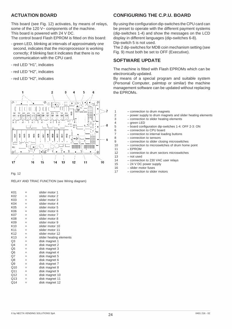
ACTUATION BOARD
This board (see Fig. 12) activates, by means of relays,some of the 120 V~ components of the machine.This board is powered with 24 V DC.The control board Flash EPROM is fitted on this board:
- green LED, blinking at intervals of approximately onesecond, indicates that the microprocessor is workingcorrectly; if blinking fast it indicates that there is nocommunication with the CPU card.
- red LED “H1”, indicates
- red LED “H2”, indicates
- red LED “H2”, indicates
CONFIGURING THE C.P.U. BOARD
By using the configuration dip-switches the CPU card canbe preset to operate with the different payment systems(dip-switches 1-4) and show the messages on the LCDdisplay in different languages (dip-switches 6-8).Dip-switch 5 is not used.The 2 dip-switches for MDB coin mechanism setting (seeFig. 9) must both be set to OFF (Executive).
SOFTWARE UPDATE
The machine is fitted with Flash EPROMs which can beelectronically updated.By means of a special program and suitable system(Personal Computer, palmtop or similar) the machinemanagement software can be updated without replacingthe EPROMs.
Fig. 12
RELAY AND TRIAC FUNCTION (see Wiring diagram)
K01 = slider motor 1K02 = slider motor 2K03 = slider motor 3K04 = slider motor 4K05 = slider motor 5K06 = slider motor 6K07 = slider motor 7K08 = slider motor 8K09 = slider motor 9K10 = slider motor 10K11 = slider motor 11K12 = slider motor 12K13 = slider heating elementsQ3 = disk magnet 1Q4 = disk magnet 2Q5 = disk magnet 3Q6 = disk magnet 4Q7 = disk magnet 5Q8 = disk magnet 6Q9 = disk magnet 7Q10 = disk magnet 8Q11 = disk magnet 9Q12 = disk magnet 10Q13 = disk magnet 11Q14 = disk magnet 12
1 – connection to drum magnets2 – power supply to drum magnets and slider heating elements3 – connection to slider heating elements4 – green LED5 – board configuration dip-switches 1-4: OFF 2-3: ON6 – connection to CPU board7 – connection to internal loading buttons8 – connection to sensors9 – connection to slider closing microswitches10 – connection to microswitches of drum home point11 – EPROM12 – connection to drum sectors microswitches13 – not used14 – connection to 230 VAC user relays15 – 24 V DC power supply16 – slider motor fuses17 – connection to slider motors
25© by NECTA VENDING SOLUTIONS SpA 0401 216 - 02
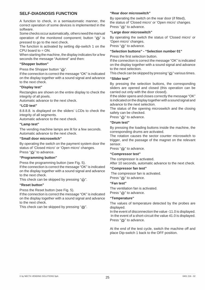
SELF-DIAGNOSIS FUNCTION
A function to check, in a semiautomatic manner, thecorrect operation of some devices is implemented in thesoftware.Some checks occur automatically, others need the manualoperation of the monitored component; button “ ” ispressed to go to the next check.The function is activated by setting dip-switch 1 on theCPU board to = ON.When starting the machine, the display indicates for a fewseconds the message “Autotest” and then:
“Shopper button”
Press the Shopper button “ ”.If the connection is correct the message “OK” is indicatedon the display together with a sound signal and advanceto the next check.
“Display test”
Rectangles are shown on the entire display to check theintegrity of all pixels.Automatic advance to the next check.
“LCD test”
8.8.8.8. is displayed on the sliders’ LCDs to check theintegrity of all segments.Automatic advance to the next check.
“Lamp test”
The vending machine lamps are lit for a few seconds.Automatic advance to the next check.
“Small door microswitch”
By operating the switch on the payment system door thestatus of ‘Closed micro’ or ‘Open micro’ changes.Press “ ” to advance.
“Programming button”
Press the programming button (see Fig. 5).If the connection is correct the message “OK” is indicatedon the display together with a sound signal and advanceto the next check.This check can be skipped by pressing “ ”.
“Reset button”
Press the Reset button (see Fig. 5).If the connection is correct the message “OK” is indicatedon the display together with a sound signal and advanceto the next check.This check can be skipped by pressing “ ”.
“Rear door microswitch”
By operating the switch on the rear door (if fitted),the status of ‘Closed micro’ or ‘Open micro’ changes.Press “ ” to advance.
“Large door microswitch”
By operating the switch the status of ‘Closed micro’ or‘Open micro’ changes.Press “ ” to advance.
“Selection buttons” - “Selection number 01”
Press the first selection button.If the connection is correct the message “OK” is indicatedon the display together with a sound signal and advanceto the next selection.This check can be skipped by pressing “ ” various times.
“Slider test”By pressing the selection buttons, the correspondingsliders are opened and closed (this operation can becarried out only with the door closed).If the slider opens and closes correctly the message “OK”is indicated on the display together with a sound signal andadvance to the next selection.The status of the opening microswitch and the closingsafety can be checked.Press “ ” to advance.
“Drum test”
By pressing the loading buttons inside the machine, thecorresponding drums are activated.The rotation causes the sector counter microswitch totrigger, and the passage of the magnet on the relevantsensor.Press “ ” to advance.
“Compressor test”
The compressor is activated.After 10 seconds, automatic advance to the next check.
“Compressor fan test” The compressor fan is activated.Press “ ” to advance.
“Fan test”The ventilation fan is activated.Press “ ” to advance.
“Temperature”
The values of temperature detected by the probes aredisplayed.In the event of disconnection the value -11.0 is displayed. In the event of a short-circuit the value 41.0 is displayed.Press “ ” to advance.
At the end of the test cycle, switch the machine off andplace Dip-switch 1 back to the OFF position.
26© by NECTA VENDING SOLUTIONS SpA 0401 216 - 02
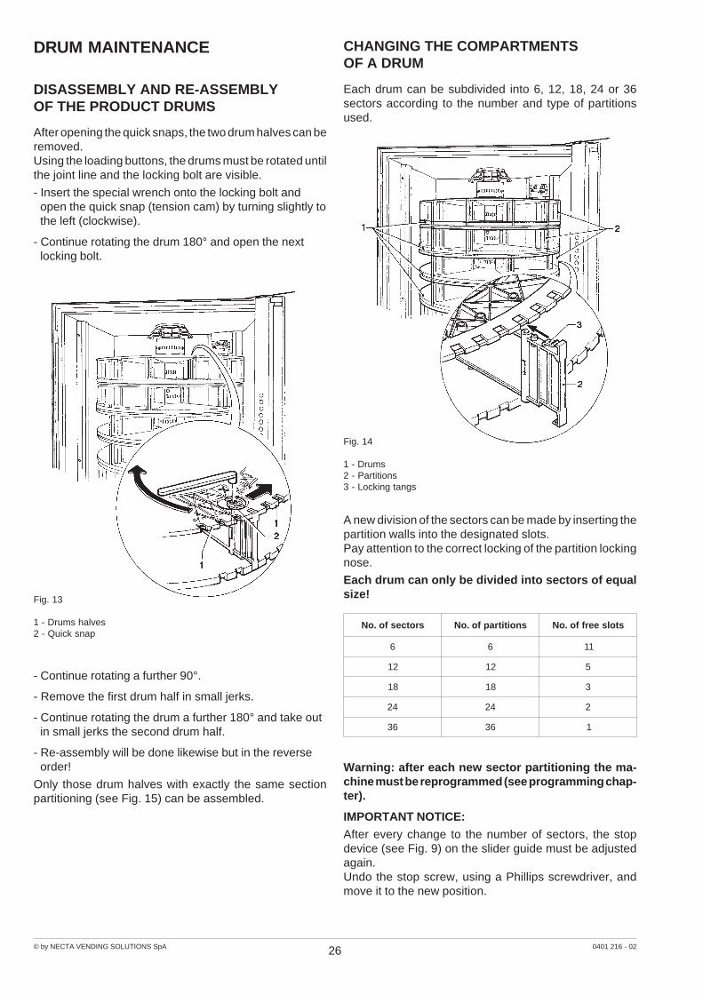
DRUM MAINTENANCE
DISASSEMBLY AND RE-ASSEMBLYOF THE PRODUCT DRUMS
After opening the quick snaps, the two drum halves can beremoved.Using the loading buttons, the drums must be rotated untilthe joint line and the locking bolt are visible.
- Insert the special wrench onto the locking bolt andopen the quick snap (tension cam) by turning slightly tothe left (clockwise).
- Continue rotating the drum 180° and open the nextlocking bolt.
Fig. 13
1 - Drums halves2 - Quick snap
- Continue rotating a further 90°.
- Remove the first drum half in small jerks.
- Continue rotating the drum a further 180° and take outin small jerks the second drum half.
- Re-assembly will be done likewise but in the reverseorder!
Only those drum halves with exactly the same sectionpartitioning (see Fig. 15) can be assembled.
CHANGING THE COMPARTMENTSOF A DRUM
Each drum can be subdivided into 6, 12, 18, 24 or 36sectors according to the number and type of partitionsused.
A new division of the sectors can be made by inserting thepartition walls into the designated slots.Pay attention to the correct locking of the partition lockingnose.
Each drum can only be divided into sectors of equalsize!
Warning: after each new sector partitioning the ma-chine must be reprogrammed (see programming chap-ter).
IMPORTANT NOTICE:
After every change to the number of sectors, the stopdevice (see Fig. 9) on the slider guide must be adjustedagain.Undo the stop screw, using a Phillips screwdriver, andmove it to the new position.
Fig. 14
1 - Drums2 - Partitions3 - Locking tangs
srotcesfo.oN snoititrapfo.oN stolseerffo.oN
6 6 11
21 21 5
81 81 3
42 42 2
63 63 1
27© by NECTA VENDING SOLUTIONS SpA 0401 216 - 02
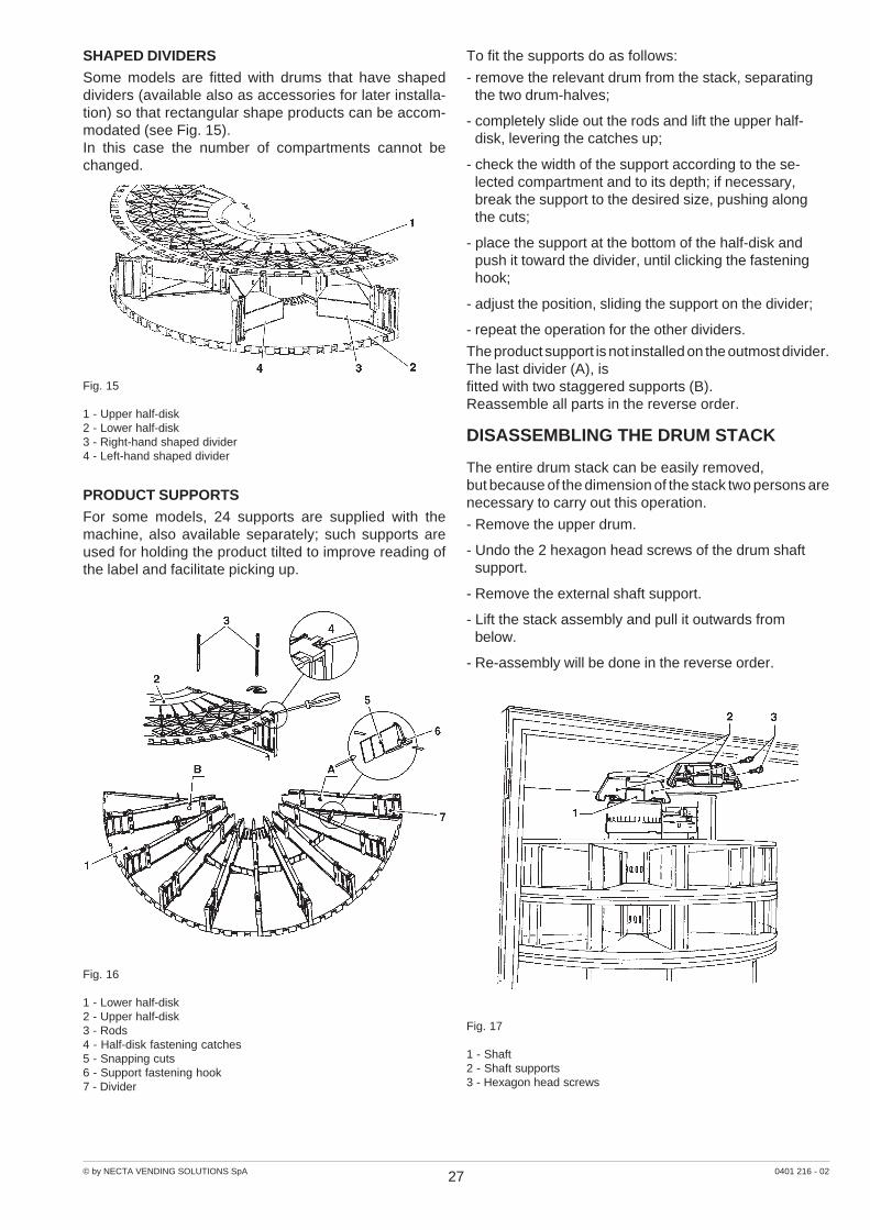
SHAPED DIVIDERS
Some models are fitted with drums that have shapeddividers (available also as accessories for later installa-tion) so that rectangular shape products can be accom-modated (see Fig. 15).In this case the number of compartments cannot bechanged.
Fig. 17
1 - Shaft2 - Shaft supports3 - Hexagon head screws
Fig. 15
1 - Upper half-disk2 - Lower half-disk3 - Right-hand shaped divider4 - Left-hand shaped divider
PRODUCT SUPPORTS
For some models, 24 supports are supplied with themachine, also available separately; such supports areused for holding the product tilted to improve reading ofthe label and facilitate picking up.
To fit the supports do as follows:
- remove the relevant drum from the stack, separatingthe two drum-halves;
- completely slide out the rods and lift the upper half-disk, levering the catches up;
- check the width of the support according to the se-lected compartment and to its depth; if necessary,break the support to the desired size, pushing alongthe cuts;
- place the support at the bottom of the half-disk andpush it toward the divider, until clicking the fasteninghook;
- adjust the position, sliding the support on the divider;
- repeat the operation for the other dividers.
The product support is not installed on the outmost divider.The last divider (A), isfitted with two staggered supports (B).Reassemble all parts in the reverse order.
DISASSEMBLING THE DRUM STACK
The entire drum stack can be easily removed,but because of the dimension of the stack two persons arenecessary to carry out this operation.
- Remove the upper drum.
- Undo the 2 hexagon head screws of the drum shaftsupport.
- Remove the external shaft support.
- Lift the stack assembly and pull it outwards frombelow.
- Re-assembly will be done in the reverse order.
Fig. 16
1 - Lower half-disk2 - Upper half-disk3 - Rods4 - Half-disk fastening catches5 - Snapping cuts6 - Support fastening hook7 - Divider

28© by NECTA VENDING SOLUTIONS SpA 0401 216 - 02
Fig. 19
1 - Compressor2 - Condenser3 - Dehumidifying filter4 - Capillary pipe5 - Evaporator
6 - Liquids trap7 - Suction pipe8 - Bypass valve9 - Hot gas pipe10 - Evaporator fans11 - Condenser fan
Fig. 20
1 Transformer primary winding fuse2 Executive coin mechanism fuse3 24 V DC fuse4 Heating element fuse5 Drum magnet fuse6 Line fuse7 Line fuse8 Main switch9 Power supply to drum magnets and heating elements10 Connection to stack motor11 Connection to door lamp12 Connection to cabinet lamp13 Power supply to coin mechanism and CPU board14 Connection to sensors15 Connection to cold unit16 Connection to control board
COOLING SYSTEM
The cooling unit is mounted onto the base.The cooling temperature, between 0° C and 3° C, is presetby the manufacturer.
MAINTENANCE AND CLEANING
The machine must be kept clean at all times, both insideand outside.Normally available products, as long as they are mild, maybe used for cleaning.When cleaning the drum halves in a dish washer, thewater temperature should never exceed 60° C.
Any detergent residue can cause unpleasant odourinside the machine!
To ensure perfect operation, the product slider guidesshould always be kept clean.
Never use grease or oil!IMPORTANT NOTICEThe drums must never come into contact with grease oroil!The condenser must be kept clean using a vacuumcleaner, a brush etc.
POWER SUPPLY UNIT
The fuses, switches and connectors which are on the frontof the power supply unit have the functions indicatedbelow.When the protective casing is fitted, only the fuses and themain switch are accessible.
When replacing any fuses the machine must be dis-connected from the power supply.
Fig. 18
1 - Stack of magnets2 - Drive cog wheel3 - Drum sliding guide4 - Rear evaporator
5 - Compressor6 - Central ventilation7 - Condenser8 - Front evaporator9 - Temperature sensor
AUTOMATIC DEFROSTING DEVICE
Automatic defrosting is enabled through programming.The defrosting system operation, indicated in Fig. 19, is asfollows:The bypass solenoid valve stays open until the sensor onthe evaporator detects a temperature of 4° C.However, the software ensures that the defrosting cycledoes not exceed 10 minutes.
The hot gas produced by the compressor flows directly tothe evaporator through the bypass pipe.With the bypass solenoid valve open the evaporator fansare stopped, to avoid a temperature increase inside therefrigerated box.
© by NECTA VENDING SOLUTIONS SpA 0401 216 - 02
29
Pro
gram
min
g bu
tton
FILL
>1
Stat
istic
s
With
the
prin
ter
conn
ecte
dpr
int
all d
ata
as d
ispl
ayed
FILL
>1.
1.1.
1Pr
int s
el. c
ount
er
Sele
ctio
ns
FILL
>1.
1.1
Parti
al p
rinto
ut
FILL
>1.
1.2
Tota
l prin
tout
FILL
>1.
1Pr
int s
tatis
tics
TO
TA
L S
TA
TIS
TIC
S
Prin
t da
ta f
or:
Sel
ectio
nsT
ime
band
sD
isco
unt/o
verp
rice
Fai
lure
sC
oin
mec
hani
sm d
ata
FILL
>1.
1.1.
1Pr
int s
el. c
ount
erFI
LL >
1.1.
1.1
Prin
t sel
. cou
nter
Con
firm
?Pr
intin
g...
FILL
>1.
1.2
Tota
l prin
tout
FILL
>1.
1.2
Tota
l prin
tout
Con
firm
?Pr
intin
g...
Hea
din
g:
Cur
rent
dat
eM
achi
ne m
odel
Sof
twar
e ed
ition
Ope
rato
r co
deM
achi
ne c
ode
Inst
alla
tion
date
Fill
er m
enu
- S
um
mar
y
Prin
t da
ta f
or:
Sel
ectio
nsT
ime
band
sD
isco
unt/o
verp
rice
Fai
lure
sC
oin
mec
hani
sm d
ata
FILL
>1.
2.1.
1Pa
rtial
prin
tout
Sele
ctio
ns
FILL
>1.
2.1
Parti
al p
rinto
ut
FILL
>1.
2.2
Tota
l prin
tout
FILL
>1.
2Pr
int r
elat
ive
stat
istic
s
RE
LA
TIV
E S
TA
TIS
TIC
S
FILL
>1.
2.1.
1Pa
rtial
prin
tout
FILL
>1.
2.1.
1Pa
rtial
prin
tout
Con
firm
?Pr
intin
g...
FILL
>1.
2.2
Tota
l prin
tout
FILL
>1.
2.2
Tota
l prin
tout
Con
firm
?Pr
intin
g...
FILL
>1.
3D
ispl
ay s
tatis
tics
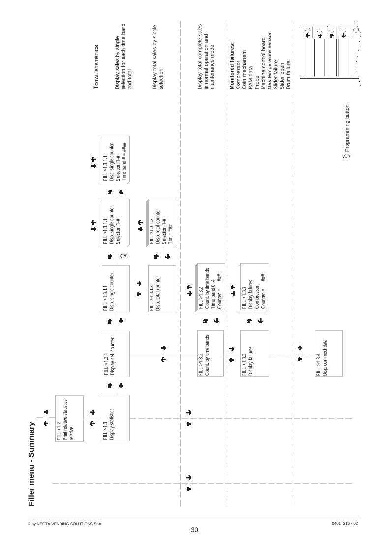
© by NECTA VENDING SOLUTIONS SpA 0401 216 - 02
30
Pro
gram
min
g bu
tton
Fill
er m
enu
- S
um
mar
y
Dis
play
sal
es b
y si
ngle
sele
ctio
n fo
r ea
ch t
ime
band
and
tota
l
Dis
play
tot
al s
ales
by
sing
lese
lect
ion
Dis
play
tot
al c
ompl
ete
sale
sin
nor
mal
ope
ratio
n an
dm
aint
enan
ce m
ode
FILL
>1.
3D
ispl
ay s
tatis
tics
FILL
>1.
3.1
Dis
play
sel
. cou
nter
FILL
>1.
3.1.
1D
isp.
sin
gle
coun
ter
FILL
>1.
3.1.
2D
isp.
tota
l cou
nter
FILL
>1.
3.1.
1D
isp.
sin
gle
coun
ter
Sele
ctio
n 1-
#Ti
me
band
# =
###
#
FILL
>1.
3.1.
1D
isp.
sin
gle
coun
ter
Sele
ctio
n 1-
#
FILL
>1.
3.1.
2D
isp.
tota
l cou
nter
Sele
ctio
n 1-
#To
t. =
###
TO
TA
L S
TA
TIS
TIC
S
FILL
>1.
2Pr
int r
elat
ive
stat
istic
sre
lativ
e
FILL
>1.
3.2
Cou
nt. b
y tim
e ba
nds
FILL
>1.
3.2
Cou
nt. b
y tim
e ba
nds
Tim
e ba
nd 0
÷4C
ount
er =
###
FILL
>1.
3.3
Dis
play
failu
res
FILL
>1.
3.3
Dis
play
failu
res
Com
pres
sor
Cou
nter
=
##
#
Mo
nit
ore
d f
ailu
res:
Com
pres
sor
Coi
n m
echa
nism
RA
M d
ata
Pro
beM
achi
ne c
ontr
ol b
oard
Gas
tem
pera
ture
sen
sor
Slid
er f
ailu
reS
lider
ope
nD
rum
fai
lure
FILL
>1.
3.4
Disp
. coin
mec
h da
ta
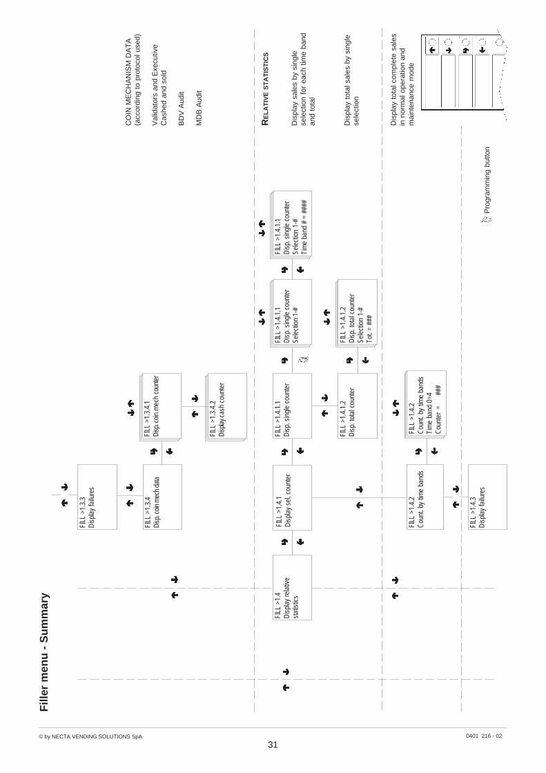
© by NECTA VENDING SOLUTIONS SpA 0401 216 - 02
31
Pro
gram
min
g bu
tton
Fill
er m
enu
- S
um
mar
y
FILL
>1.
3.3
Dis
play
failu
res
FILL
>1.
3.4
Disp
. coin
mec
h da
ta
CO
IN M
EC
HA
NIS
M D
AT
A(a
ccor
ding
to
prot
ocol
use
d)
Val
idat
ors
and
Exe
cutiv
eC
ashe
d an
d so
ld
BD
V A
udit
MD
B A
udit
FILL
>1.
3.4.
1Di
sp. c
oin
mec
h co
unte
r
FILL
>1.
3.4.
2Di
splay
cas
h co
unte
r
Dis
play
sal
es b
y si
ngle
sele
ctio
n fo
r ea
ch t
ime
band
and
tota
l
Dis
play
tot
al s
ales
by
sing
lese
lect
ion
FILL
>1.
4D
ispl
ay re
lativ
est
atis
tics
FILL
>1.
4.1
Dis
play
sel
. cou
nter
FILL
>1.
4.1.
1D
isp.
sin
gle
coun
ter
FILL
>1.
4.1.
2D
isp.
tota
l cou
nter
FILL
>1.
4.1.
1D
isp.
sin
gle
coun
ter
Sele
ctio
n 1-
#Ti
me
band
# =
###
#
FILL
>1.
4.1.
1D
isp.
sin
gle
coun
ter
Sele
ctio
n 1-
#
FILL
>1.
4.1.
2D
isp.
tota
l cou
nter
Sele
ctio
n 1-
#To
t. =
###
RE
LA
TIV
E S
TA
TIS
TIC
S
FILL
>1.
4.2
Cou
nt. b
y tim
e ba
nds
FILL
>1.
4.2
Cou
nt. b
y tim
e ba
nds
Tim
e ba
nd 0
÷4C
ount
er =
###
Dis
play
tot
al c
ompl
ete
sale
sin
nor
mal
ope
ratio
n an
dm
aint
enan
ce m
ode
FILL
>1.
4.3
Dis
play
failu
res

© by NECTA VENDING SOLUTIONS SpA 0401 216 - 02
32
Pro
gram
min
g bu
tton
FILL
>1.
4.2
Cou
nt. b
y tim
e ba
nds
FILL
>1.
4.3
Dis
play
failu
res
FILL
>1.
4.3
Dis
play
failu
res
Com
pres
sor
Cou
nter
=
##
#
Mo
nit
ore
d f
ailu
res:
Com
pres
sor
Coi
n m
echa
nism
RA
M d
ata
Pro
beM
achi
ne c
ontr
ol b
oard
Gas
tem
pera
ture
sen
sor
Slid
er f
ailu
reS
lider
ope
nD
rum
fai
lure
FILL
>1.
4.4
Disp
. coin
mec
h da
ta
CO
IN M
EC
HA
NIS
M D
AT
A(a
ccor
ding
to
prot
ocol
use
d)
Val
idat
ors
and
Exe
cutiv
eC
ashe
d an
d so
ld
BD
V A
udit
MD
B A
udit
FILL
>1.
4.4.
1Di
sp. c
oin
mec
h co
unte
r
FILL
>1.
4.4.
2Di
splay
cas
h co
unte
r
Fill
er m
enu
- S
um
mar
y
RE
LA
TIV
E S
TA
TIS
TIC
S
Del
ete
data
for
:S
elec
tions
Dis
coun
t/ove
rpric
eF
ailu
res
Coi
n m
echa
nism
dat
a
FILL
>1.
5.1.
1D
elet
e pa
rtial
Sele
ctio
ns
FILL
>1.
5.1
Del
ete
parti
alFI
LL >
1.5
Del
ete
rela
tive
stat
istic
s
RE
LA
TIV
E S
TA
TIS
TIC
S
FILL
>1.
5.1.
1D
elet
e pa
rtial
FILL
>1.
5.1.
1D
elet
e pa
rtial
Con
firm
?Pr
intin
g...
FILL
>1.
5.2
Del
ete
tota
lFI
LL >
1.5.
2.1
Del
ete
tota
lFI
LL >
1.5.
2.1
Del
ete
tota
l
Con
firm
?Pr
intin
g...
FILL
>2
Pric
es

© by NECTA VENDING SOLUTIONS SpA 0401 216 - 02
33
Pro
gram
min
g bu
tton
FILL
>1
Stat
istic
s
FILL
>2
Pric
es
Fill
er m
enu
- S
um
mar
y
Opt
ion
of c
hang
ing
sale
spr
ice
for
each
dru
m
X +
1
X - 1
FILL
>2.
1Se
lect
dru
m
#FI
LL >
2.1
Sele
ctio
n #
Pric
e##
##
FILL
>3.1
Fill
tube
sFI
LL>3
.1Fi
ll tu
bes
Cre
dit:#
####
BD
V o
nly
Man
ual c
hang
e tu
be r
efill
FILL
>3Tu
be c
ontro
l
FILL
>3.2
Rel
ease
tube
s
Cre
dit:#
####
Man
ual t
ube
rele
asin
g
FILL
>3.2
Tube
A ÷
XR
elea
se o
ne c
oin
from
the
activ
e tu
be
FILL
>4Ai
rflow
adj
ustm
ent
FILL
>4.1
Posi
tioni
ng s
tack
FILL
>4.2
Posi
tioni
ng d
rum
Pre
ss b
utto
n t
o ro
tate
all
drum
s
Pre
ss a
load
ing
butto
n to
rele
ase
the
corr
espo
ndin
gm
agne
t fo
r m
anua
l rot
atio
n
FILL
>5An
ti-ta
mpe
ring

© by NECTA VENDING SOLUTIONS SpA 0401 216 - 02
34
Pro
gram
min
g bu
tton
Fill
er m
enu
- S
um
mar
y
FILL
>6.1
Dru
m te
st
FILL
>6.2
Slid
er te
st
FILL
>6.1
Sele
ctdr
um#
FILL
>6.2
Sele
ctsl
ider
#
Pre
ss a
sel
ectio
n bu
tton
Pre
ss a
sel
ectio
n bu
tton
FILL
>1Fa
ilure
s
FILL
>5An
ti-ta
mpe
ring
FILL
>6.3
Com
plet
e se
lect
ion
FILL
>6.3
Sele
ctdr
um#
Pre
ss a
sel
ectio
n bu
tton
FILL
>6Te
st
FILL
>5.1
Anti-
tam
perin
g
FILL
>7.1
Res
et p
re-a
larm
coun
ters
FILL
>7G
SM
FILL
>8EV
ADTS
FILL
>8.1
Con
nect
ion
FILL
>7.1
Del
ete
tota
lFI
LL>7
.1D
elet
e to
tal
Con
firm
?W
orki
ng...
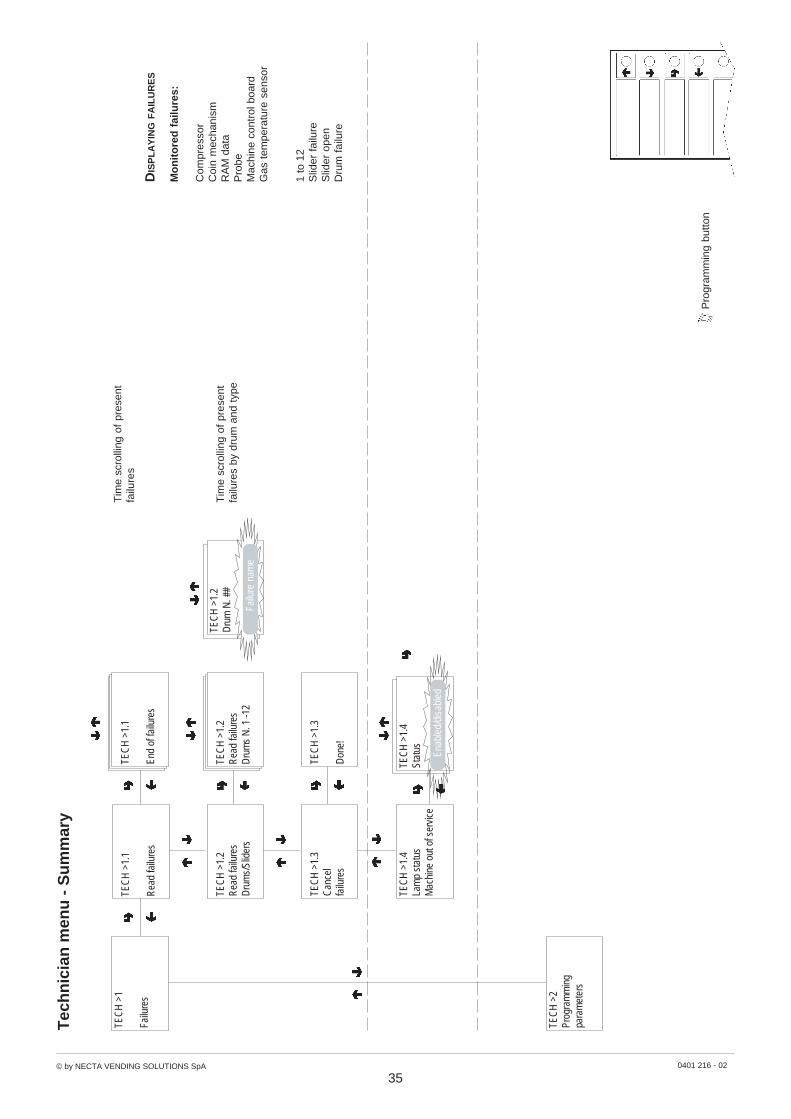
© by NECTA VENDING SOLUTIONS SpA 0401 216 - 02
35
Pro
gram
min
g bu
tton
Tec
hn
icia
n m
enu
- S
um
mar
y
Mo
nit
ore
d f
ailu
res:
Com
pres
sor
Coi
n m
echa
nism
RA
M d
ata
Pro
beM
achi
ne c
ontr
ol b
oard
Gas
tem
pera
ture
sen
sor
DIS
PL
AY
ING F
AIL
UR
ES
TEC
H >
1.3
Can
cel
failu
res
TEC
H >
1.3
Don
e!
TEC
H >
1.1
End
of fa
ilure
s
TEC
H >
1
Failu
res
TEC
H >
1.2
Rea
d fa
ilure
sD
rum
s/Sl
ider
s
TEC
H >
1.2
Rea
d fa
ilure
sD
rum
s N
. 1 -1
2
TEC
H >
1.2
Dru
m N
. ##
Failu
re n
ame
1 to
12
Slid
er f
ailu
reS
lider
ope
nD
rum
fai
lure
Tim
e sc
rolli
ng o
f pr
esen
tfa
ilure
s
Tim
e sc
rolli
ng o
f pr
esen
tfa
ilure
s by
dru
m a
nd t
ype
TEC
H >
1.1
Rea
d fa
ilure
s
TEC
H >
1.4
Stat
us Enab
led/
disa
bled
TEC
H >
1.4
Lam
p st
atus
Mac
hine
out
of s
ervi
ce
TEC
H >
2Pr
ogra
mm
ing
para
met
ers

© by NECTA VENDING SOLUTIONS SpA 0401 216 - 02
36
Pro
gram
min
g bu
tton
Tec
hn
icia
n m
enu
- S
um
mar
y
4 tim
e ba
nds
plus
ban
d 0
(no
time
band
set)
ava
ilabl
e w
ith d
iffer
ent
pric
es f
orea
ch s
elec
tion,
app
licab
le t
o th
e en
tire
wee
k or
onl
y to
som
e da
ys
X +
1
X - 1
TEC
H >
2.1.
1.2.
1Ti
me
band
0 -
4
TEC
H >
2.1.
1.1
Sing
lese
lect
ion
TEC
H >
2.1.
1.1.
1Ti
me
band
0 -
4TE
CH
>2.
1.1.
1.1
Tim
e ba
nd
#Se
lect
dru
m
#
TEC
H >
2.1.
1.2.
1
Tim
e ba
nd #
Pric
e##
##
TEC
H >
2.1.
1.1.
1Ti
me
band
#"
Sele
ctio
n #
Pric
e #
###
TEC
H >
2.1.
1.2
Glo
bal
sele
ctio
ns
TEC
H >
2.1.
1.1.
1Ti
me
band
#
Wee
k - D
ay 1
÷ 7
TEC
H >
2.1.
1Pr
ices
TEC
H >
2Pr
ogra
mm
ing
para
met
ers
TEC
H >
2.1.
1.2.
1Ti
me
band
#
Wee
k - D
ay 1
÷ 7
####
TEC
H >
2.1
Cas
h
TEC
H >
2.1.
1.3.
2Ti
me
band
1St
art b
and
##
End
band
##
##
CL
OC
K
Whe
n co
nfirm
ing
the
blin
king
val
ues,
day,
mon
th, y
ear
and
wee
k da
y ar
een
tere
d on
e af
ter
the
othe
r. W
hen
conf
irmin
g th
e w
eek
day
hour
and
min
utes
are
dis
play
ed,
that
can
the
n be
chan
ged
and
conf
irmed
.
TIM
E B
AN
DS
Whe
n co
nfirm
ing
the
blin
king
val
ues,
hour
and
min
ute
for
star
t an
d en
d of
tim
eba
nd a
re e
nter
ed o
ne a
fter
the
othe
r.W
hen
star
t an
d en
d of
tim
e ba
nd a
re s
etto
24.
00 t
he b
ands
are
not
act
ivat
ed.
TEC
H >
2.1.
1.3
Tim
e ba
nds
TEC
H >
2.1.
1.3.
1Se
t dat
e an
d tim
e
TEC
H >
2.1.
1.3.
2Ti
me
band
1- 4
##
TEC
H >
2.1.
1.3.
1Se
t dat
e an
d tim
e
Tim
e:
/##
TEC
H >
2.1.
1.3.
1Se
t dat
e an
d tim
e
Dat
e:
/##/
## d
d### ##
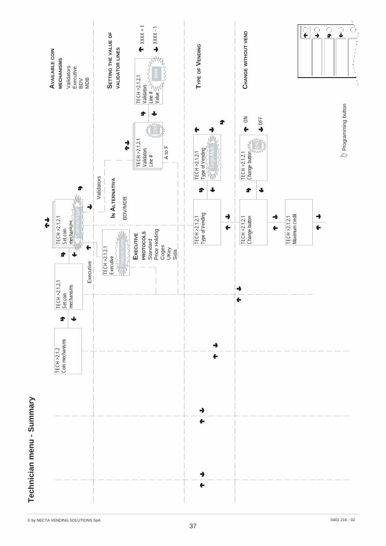
© by NECTA VENDING SOLUTIONS SpA 0401 216 - 02
37
Pro
gram
min
g bu
tton
Tec
hn
icia
n m
enu
- S
um
mar
y
AV
AIL
AB
LE C
OIN
ME
CH
AN
ISM
S
Val
idat
ors
Exe
cutiv
eB
DV
MD
B
TY
PE O
F V
EN
DIN
G
CH
AN
GE W
ITH
OU
T V
EN
D
TEC
H >
2.1.
2C
oin
mec
hani
sms
TEC
H >
2.1.
2.1
Set c
oin
mec
hani
sms
TEC
H >
2.1.
2.1
Type
of V
endi
ngTE
CH
>2.
1.2.
1Ty
pe o
f Ven
ding
TEC
H >
2.1.
2.1
Cha
nge
butto
nTE
CH
>2.
1.2.
1C
hang
e bu
tton
TEC
H >
2.1.
2.1
Max
imum
cre
dit
TEC
H >
2.1.
2.1
Set c
oin
mec
hani
sms
"Coi
n m
ech
type
"
TEC
H >
2.1.
2.1
Valid
ator
sLi
ne #
Valu
e##
##
IN A
LT
ER
NA
TIV
A
BD
V/M
DBV
alid
ator
s
Exe
cutiv
e
A to
F
XXXX
+ 1
XXXX
- 1
SE
TT
ING
TH
E V
AL
UE O
F
VA
LID
AT
OR L
INE
S
Sing
le/M
ulti
TEC
H >
2.1.
2.1
Valid
ator
sLi
ne #
ON
EX
EC
UT
IVE
PR
OT
OC
OL
SS
tand
ard
Pric
e H
oldi
ngC
oges
UK
eyS
ida
TEC
H >
2.1.
2.1
Exec
utiv
e
Prot
ocol
nam
e
ON
OFF
ON

© by NECTA VENDING SOLUTIONS SpA 0401 216 - 02
38
Pro
gram
min
g bu
tton
Tec
hn
icia
n m
enu
- S
um
mar
y
XXXX
+ 1
XXXX
- 1
TEC
H >
2.1.
2.1
Max
imum
cre
dit
TEC
H >
2.1.
2.1
Valu
e =
####
#
TEC
H >
2.1.
2.1
Valu
e =
Coi
ns A
to F
XXXX
+ 1
XXXX
- 1
TEC
H >
2.1.
2.1
Max
imum
cha
nge
TEC
H >
2.1.
2.1
Valu
e =
####
#
TEC
H >
2.1.
2.1
Acce
pted
coi
nsTE
CH
>2.
1.2.
1C
oin
ATE
CH
>2.
1.2.
1C
oin
A
Coi
ns A
to F
TEC
H >
2.1.
2.1
Not
acc
epte
d co
ins
TEC
H >
2.1.
2.1
Coi
n A
TEC
H >
2.1.
2.1
Coi
n A
TEC
H >
2.1.
2.1
Dis
pens
ing
butto
ns
TEC
H >
2.1.
2.1
Butto
nE
nabl
e
Dis
able
A DA
TEC
H >
2.1.
2.1
Exac
t am
ount
Coi
n re
turn
tube
rel
ease
butto
ns
####
TEC
H >
2.1.
2.1
Valu
e =
####
Ena
ble
Dis
able
Yes
No
Ena
ble
Dis
able
Yes
No
Yes
Yes

© by NECTA VENDING SOLUTIONS SpA 0401 216 - 02
39
Pro
gram
min
g bu
tton
Tec
hn
icia
n m
enu
- S
um
mar
y
TEC
H >
2.1.
2.1
Exac
t am
ount
TEC
H >
2.1.
2.1
Com
bina
tion
1-12
TEC
H >
2.1.
2.1
Com
bina
tion ##
##
TEC
H >
2.1.
2.1
Valu
e =
TEC
H >
2.1.
2.1
Valu
e =
####
#
TEC
H >
2.1.
2.1
C.P
.C.
devi
ce
TEC
H >
2.1.
2.1
C.P
.C.
devi
ce
TEC
H >
2.1.
2.1
Empt
y-st
ate
leve
l
TEC
H >
2.1.
2.2
Imm
edia
te c
hang
e
Ena
ble
Dis
able
A D
XXXX
+ 1
XXXX
- 1
####
#
A
#
TEC
H >
2.1.
2.2
Imm
edia
te c
hang
eE
nabl
e
Dis
able
A DA
0 =
A o
r (B
and
C)
1 =
A a
nd B
and
C2
= A
and
B o
nly
3 =
A a
nd (
B o
r C
)4
= A
onl
y5
= A
or
B o
nly
(def
ault)
6 =
A o
r B
or
C7
= A
or
B o
nly
8 =
A o
r C
onl
y9
= B
and
C o
nly
10 =
B o
nly
11 =
B o
r C
onl
y12
= C
onl
y
TEC
H >
2.1.
3D
ecim
alpo
int
0 to
3

© by NECTA VENDING SOLUTIONS SpA 0401 216 - 02
40
Pro
gram
min
g bu
tton
Tec
hn
icia
n m
enu
- S
um
mar
y
TEC
H >
2.1.
3D
ecim
alpo
int
0 to
3
TEC
H >
2.1.
4Fr
ee v
end
bonu
s
TEC
H >
2.2
Dru
ms/
Slid
ers
TEC
H >
2.1.
4En
able
Bon
usO
NO
N
OF
F
TEC
H >
2.1.
4Bo
nus
frequ
ency
one
ever
y
##
# se
l.#
If O
N t
he a
vera
ge n
umbe
r of
sele
ctio
ns (
0001
to
9999
)be
twee
n tw
o bo
nuse
s is
requ
este
d
TEC
H >
2.1.
3N
umbe
rof
dec
imal
#

© by NECTA VENDING SOLUTIONS SpA 0401 216 -02
41
Pro
gram
min
g bu
tton
Tec
hn
icia
n m
enu
- S
um
mar
y
TEC
H >
2.2
Dru
ms/
Slid
ers
TEC
H >
2.2.
1D
rum
par
amet
ers
TEC
H >
2.2.
1.2
Dru
m #
Stat
us
TEC
H >
2.2.
1.1
Type
of V
endi
ng F
IFO
TEC
H >
2.2.
1.1
Type
of V
endi
ng FI
FOFI
FO
Shop
per
TEC
H >
2.2.
1.2
Sele
ctdr
um #
AEn
able
d
Dis
able
d
TEC
H >
2.2.
1.4
Dru
m e
xpiry
dat
e
TEC
H >
2.2.
1.3.
1Ti
me
band
#D
ay #
Dru
m #
A
Enab
led
Dis
able
dTE
CH
>2.
2.1.
4D
rum
exp
iry d
ate
Dru
m 1
-12
X +
1
X - 1
TEC
H >
2.2.
1.3
Dru
m s
tatu
s ##
Tim
e ba
nd #
TEC
H >
2.2.
1.3.
1Ti
me
band
1 -
4TE
CH
>2.
2.1.
3.1
Tim
e ba
nd #
Wee
k - D
ay 1
- 7
TEC
H >
2.2.
1.3.
1Ti
me
band
#D
ay #
Dru
m 1
-12
TEC
H >
2.2.
1.4
Dru
m e
xpiry
dat
eD
rum
#D
ays
#
TEC
H >
2.2.
1.5
Dru
m ro
tatio
nTE
CH
>2.
2.1.
5D
rum
rota
tion
Slid
er 1
-12
X +
1
X - 1
TEC
H >
2.2.
1.5
Dru
m ro
tatio
nD
rum
#Se
cond
s:##
Sta
tus
appl
icab
le t
oen
tire
wee
k or
onl
y to
som
e da
ys

© by NECTA VENDING SOLUTIONS SpA 0401 216 -02
42
Pro
gram
min
g bu
tton
Tec
hn
icia
n m
enu
- S
um
mar
y
TEC
H >
2.2.
1.6
Dru
m c
ode
TEC
H >
2.2.
1.6
Dru
m c
ode
Cod
e =
###
#
4-di
git
num
ber
iden
tifyi
ngth
e dr
um
TEC
H >
2.2.
2.1
Ope
n sl
ider
TEC
H >
2.2.
2.1
Ope
n sl
ider
Slid
er 1
-12
X +
1
X - 1
TEC
H >
2.2.
2.1
Ope
n sl
ider
Slid
er #
Seco
nds:
##
TEC
H >
2.3
Col
d pa
ram
eter
s
TEC
H >
2.2.
2Sl
ider
par
amet
ers
Ope
ratin
g te
mpe
ratu
re3°
C t
o 15
°C.
3°C
by
defa
ult
TEC
H >
2.3.
1.1
Col
d pa
ram
eter
sIn
tern
al te
mpe
ratu
re
TEC
H >
2.3.
1.1
Col
d pa
ram
eter
sIn
t. te
mpe
ratu
re =
##
X +
1
X - 1
TEC
H >
2.3.
1.2
Col
d pa
ram
eter
sSa
fety
tem
pera
ture
TEC
H >
2.3.
1.2
Col
d pa
ram
eter
sTe
mpe
rat.
S ic
.A
TEC
H >
2.3.
1.3
Col
d pa
ram
eter
sTe
mpe
ratu
re lo
g
TEC
H >
2.3.
1.3
Inte
rnal
tem
pera
ture
Dat
e:xx
.xx.
xxtim
e:xx
.xx
Tem
pera
ture
°C
xx
Enab
led
Dis
able
d
TEC
H >
2.3.
1Te
mpe
ratu
re
TEC
H >
2.3.
2D
efro
stin
g
+10
min
utes
-10
min
utes
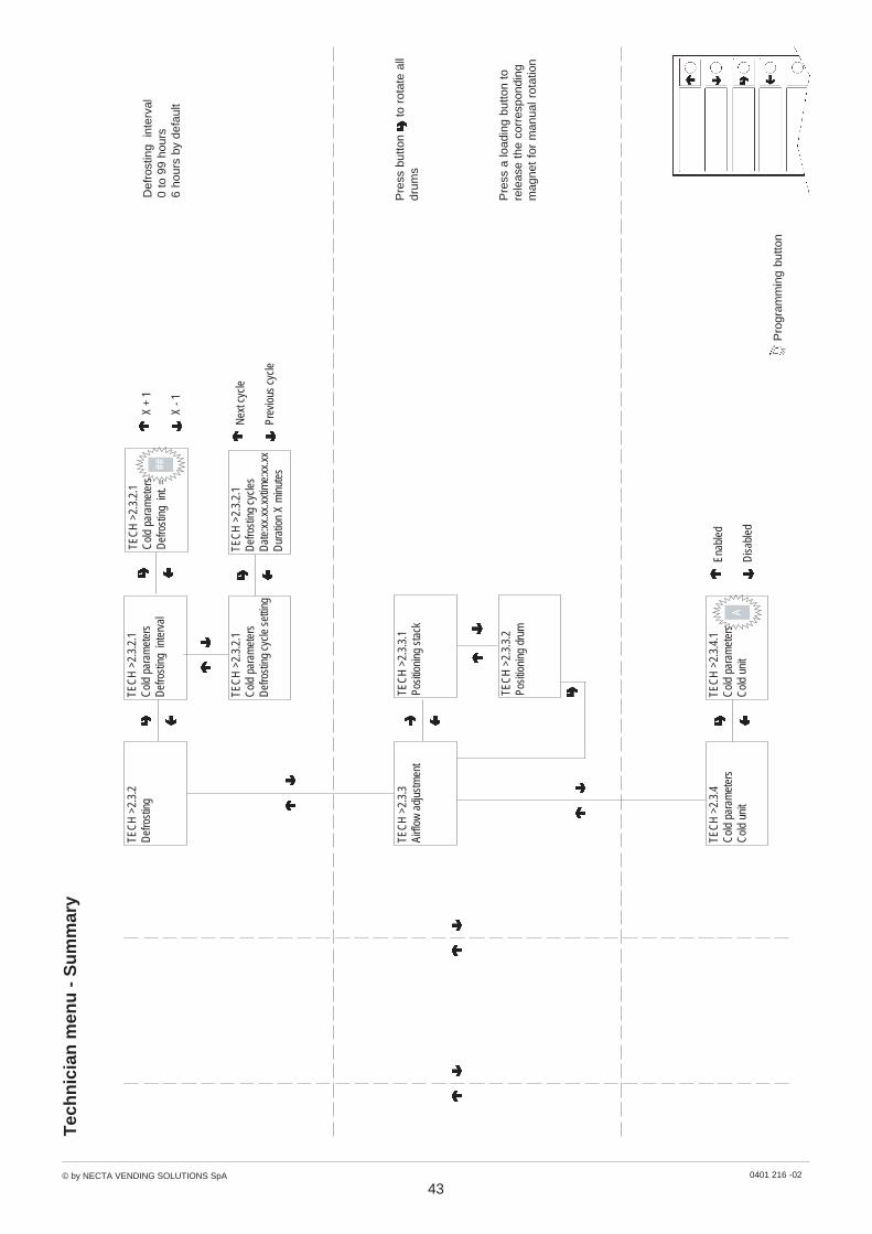
© by NECTA VENDING SOLUTIONS SpA 0401 216 -02
43
Pro
gram
min
g bu
tton
Tec
hn
icia
n m
enu
- S
um
mar
y
TEC
H >
2.3.
4C
old
para
met
ers
Col
d un
it
TEC
H >
2.3.
4.1
Col
d pa
ram
eter
sC
old
unit
A
Enab
led
Dis
able
d
X +
1
X - 1
Def
rost
ing
inte
rval
0 to
99
hour
s6
hour
s by
def
ault
TEC
H >
2.3.
2.1
Col
d pa
ram
eter
sD
efro
stin
g in
terv
al
TEC
H >
2.3.
2.1
Col
d pa
ram
eter
sD
efro
stin
g in
t. =
##
TEC
H >
2.3.
2.1
Col
d pa
ram
eter
sD
efro
stin
g cy
cle
setti
ng
TEC
H >
2.3.
2.1
Def
rost
ing
cycl
esD
ate:
xx.x
x.xx
time:
xx.x
xD
urat
ion
X m
inut
es
Nex
t cyc
le
Prev
ious
cyc
le
TEC
H >
2.3.
3Ai
rflow
adj
ustm
ent
TEC
H >
2.3.
2D
efro
stin
g
TEC
H >
2.3.
3.1
Posi
tioni
ng s
tack
TEC
H >
2.3.
3.2
Posi
tioni
ng d
rum
Pre
ss b
utto
n t
o ro
tate
all
drum
s
Pre
ss a
load
ing
butto
n to
rele
ase
the
corr
espo
ndin
gm
agne
t fo
r m
anua
l rot
atio
n
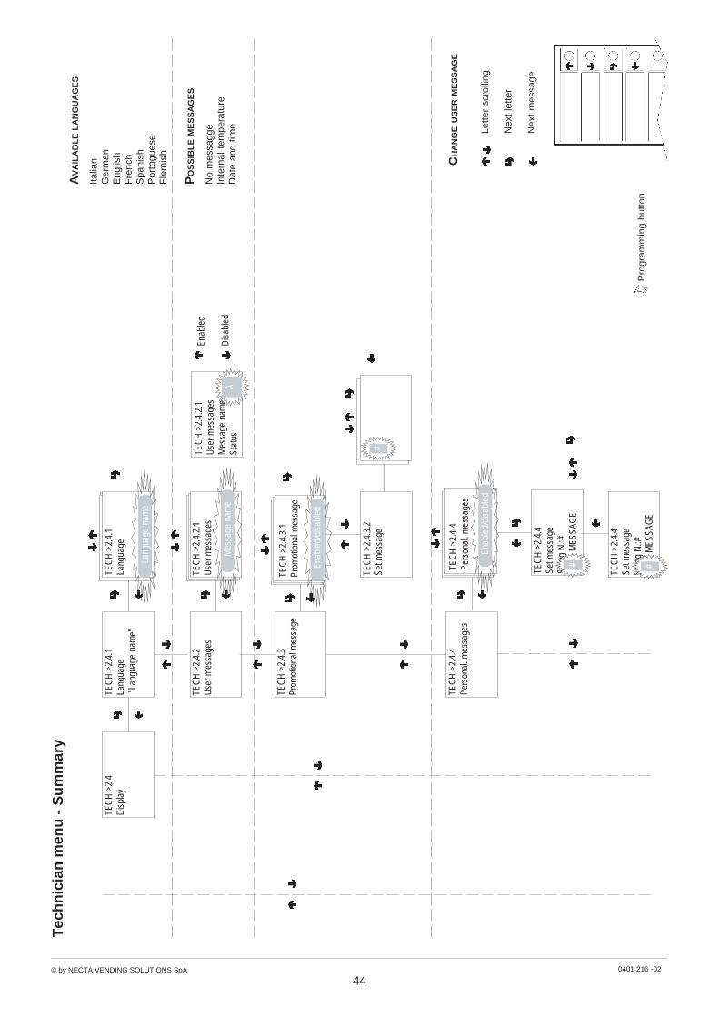
© by NECTA VENDING SOLUTIONS SpA 0401 216 -02
44
Pro
gram
min
g bu
tton
Tec
hn
icia
n m
enu
- S
um
mar
y
TEC
H >
2.4
Dis
play
Italia
nG
erm
anE
nglis
hF
renc
hS
pani
shP
orto
gues
eF
lem
ish
AV
AIL
AB
LE L
AN
GU
AG
ES
TEC
H >
2.4.
1La
ngua
ge "L
angu
age
nam
e"
TEC
H >
2.4.
2U
ser m
essa
ges
TEC
H >
2.4.
1La
ngua
ge
Lang
uage
nam
e
TEC
H >
2.4.
2.1
Use
r mes
sage
sTE
CH
>2.
4.2.
1U
ser m
essa
ges
Mes
sage
nam
eSt
atus
Enab
led
Dis
able
d
No
mes
sagg
eIn
tern
al t
empe
ratu
reD
ate
and
time
PO
SS
IBL
E M
ES
SA
GE
S
TEC
H >
2.4.
3Pr
omot
iona
l mes
sage
TEC
H >
2.4.
3.1
Prom
otio
nal m
essa
ge
Enab
led/
disa
bled
#TE
CH
>2.
4.3.
2Se
t mes
sage
Mes
sage
nam
e
TEC
H >
2.4.
4Pe
rson
al. m
essa
ges
TEC
H >
2.4.
4Pe
rson
al. m
essa
ges
Enab
led/
disa
bled
TEC
H >
2.4.
4Se
t mes
sage
Strin
g N
.:#
MES
SAG
E#
Le
tter
scro
lling
Nex
t le
tter
Nex
t m
essa
ge
CH
AN
GE U
SE
R M
ES
SA
GE
TEC
H >
2.4.
4Se
t mes
sage
Strin
g N
.:#
MES
SAG
E#
A

© by NECTA VENDING SOLUTIONS SpA 0401 216 -02
45
Pro
gram
min
g bu
tton
Tec
hn
icia
n m
enu
- S
um
mar
y
TEC
H >
2.4.
5D
ispl
ay E
uro
TEC
H >
2.4.
5D
ispl
ay
Enab
led/
disa
bled
Enab
led
Dis
able
d
TEC
H >
2.4.
6D
is. c
ount
at s
tart-
upSt
atus
Enab
led/
disa
bled
TEC
H >
2.4.
6D
ispl
ay c
ount
erat
sta
rt-up
Enab
led
Dis
able
d
TEC
H >
2.5
Mis
cella
neou
sTE
CH
>2.
5.1
Pass
wor
d
TEC
H >
2.5.
1.2
Stat
us
Fiv
e-di
git
num
ber
to a
cces
spr
ogra
mm
ing.
If se
t to
Zer
o (d
efau
lt) t
hepa
ssw
ord
is n
ot r
equi
red.
TEC
H >
2.5.
1.1
Pass
wor
d
TEC
H >
2.5.
1.2
Pass
wor
d
TEC
H >
2.5.
1.1
Ente
r pas
swor
d
Pass
wor
d =
#
###
Enab
led/
disa
bled
Whe
n co
nfirm
ing
the
blin
king
valu
es,
hour
and
min
ute
for
star
t an
d en
d of
tim
e ba
ndar
e en
tere
d on
e af
ter
the
othe
r.W
hen
star
t an
d en
d of
tim
eba
nd a
re s
et t
o 00
.00
the
band
s ar
e no
t ac
tivat
ed.
TEC
H >
2.5.
2.2
Tim
e ba
nd 1
÷ 2
TEC
H >
2.5.
2.2
Tim
e ba
nd 1
Star
t ban
d
#
#En
d ba
nd #
# ####
TEC
H >
2.5.
2.2
Day
1÷
7
TEC
H >
2.5.
2En
ergy
sav
ing
TEC
H >
2.5.
2.1
Ener
gy s
avin
g
Enab
led/
disa
bled
TEC
H >
2.5.
2.1
Switc
h of
f lam
ps
Enab
led/
disa
bled
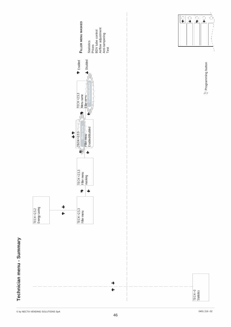
© by NECTA VENDING SOLUTIONS SpA 0401 216 -02
46
Pro
gram
min
g bu
tton
Tec
hn
icia
n m
enu
- S
um
mar
y
TEC
H >
2.5.
3Fi
ller m
enu
TEC
H >
3St
atis
tics
TEC
H >
2.5.
3Fi
ller m
enu
mas
king
Men
u na
me
TEC
H >
2.5.
3
Fille
r men
uEn
able
d/di
sabl
ed
Enab
led
Dis
able
d
TEC
H >
2.5.
3M
enu
nam
eFi
ller m
enu
Enab
led/
disa
bled
Sta
tistic
sP
rices
BD
V t
ube
cont
rol
Airf
low
adj
ustm
ent
Ant
i-tam
perin
gT
est
FIL
LE
R M
EN
U M
AS
KE
D
TEC
H >
2.5.
2En
ergy
sav
ing
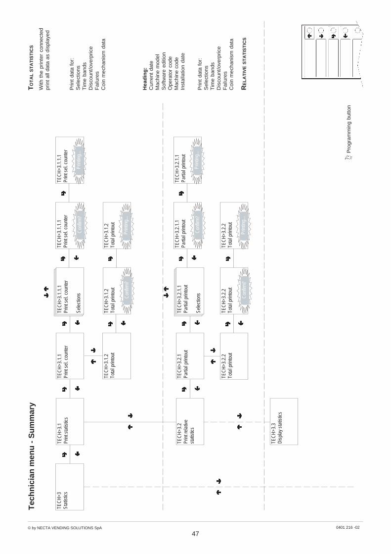
© by NECTA VENDING SOLUTIONS SpA 0401 216 -02
47
Pro
gram
min
g bu
tton
Tec
hn
icia
n m
enu
- S
um
mar
y
TEC
H>3
Stat
istic
s
With
the
prin
ter
conn
ecte
dpr
int
all d
ata
as d
ispl
ayed
TEC
H>3
.1.1
.1Pr
int s
el. c
ount
er
Sele
ctio
ns
TEC
H>3
.1.1
Prin
t sel
. cou
nter
TEC
H>3
.1.2
Tota
l prin
tout
TEC
H>3
.1Pr
int s
tatis
tics
TO
TA
L S
TA
TIS
TIC
S
Prin
t da
ta f
or:
Sel
ectio
nsT
ime
band
sD
isco
unt/o
verp
rice
Fai
lure
sC
oin
mec
hani
sm d
ata
TEC
H>3
.1.1
.1Pr
int s
el. c
ount
erTE
CH
>3.1
.1.1
Prin
t sel
. cou
nter
Con
firm
?Pr
intin
g...
TEC
H>3
.1.2
Tota
l prin
tout
TEC
H>3
.1.2
Tota
l prin
tout
Con
firm
?Pr
intin
g...
Hea
din
g:
Cur
rent
dat
eM
achi
ne m
odel
Sof
twar
e ed
ition
Ope
rato
r co
deM
achi
ne c
ode
Inst
alla
tion
date
Prin
t da
ta f
or:
Sel
ectio
nsT
ime
band
sD
isco
unt/o
verp
rice
Fai
lure
sC
oin
mec
hani
sm d
ata
TEC
H>3
.2.1
.1Pa
rtial
prin
tout
Sele
ctio
ns
TEC
H>3
.2.1
Parti
al p
rinto
ut
TEC
H>3
.2.2
Tota
l prin
tout
TEC
H>3
.2Pr
int r
elat
ive
stat
istic
s
RE
LA
TIV
E S
TA
TIS
TIC
S
TEC
H>3
.2.1
.1Pa
rtial
prin
tout
TEC
H>3
.2.1
.1Pa
rtial
prin
tout
Con
firm
?Pr
intin
g...
TEC
H>3
.2.2
Tota
l prin
tout
TEC
H>3
.2.2
Tota
l prin
tout
Con
firm
?Pr
intin
g...
TEC
H>3
.3D
ispl
ay s
tatis
tics

© by NECTA VENDING SOLUTIONS SpA 0401 216 -02
48
Pro
gram
min
g bu
tton
Tec
hn
icia
n m
enu
- S
um
mar
y
Dis
play
sal
es b
y si
ngle
sele
ctio
n fo
r ea
ch t
ime
band
and
tota
l
Dis
play
tot
al s
ales
by
sing
lese
lect
ion
Dis
play
tot
al c
ompl
ete
sale
sin
nor
mal
ope
ratio
n an
dm
aint
enan
ce m
ode
TEC
H>3
.3D
ispl
ay s
tatis
tics
TEC
H>3
.3.1
Dis
play
sel
. cou
nter
TEC
H>3
.3.1
.1D
isp.
sin
gle
coun
ter
TEC
H>3
.3.1
.2D
isp.
tota
l cou
nter
TEC
H>3
.3.1
.1D
isp.
sin
gle
coun
ter
Sele
ctio
n 1-
#Ti
me
band
# =
###
#
TEC
H>3
.3.1
.1D
isp.
sin
gle
coun
ter
Sele
ctio
n 1-
#
TEC
H>3
.3.1
.2D
isp.
tota
l cou
nter
Sele
ctio
n 1-
#To
t. =
###
TO
TA
L S
TA
TIS
TIC
S
TEC
H>3
.2Pr
int r
elat
ive
stat
istic
s
TEC
H>3
.3.2
Cou
nt. b
y tim
e ba
nds
TEC
H>3
.3.2
Cou
nt. b
y tim
e ba
nds
Tim
e ba
nd 0
÷4C
ount
er =
###
TEC
H>3
.3.3
Dis
play
failu
res
TEC
H>3
.3.3
Dis
play
failu
res
Com
pres
sor
Cou
nter
=
##
#
Mo
nit
ore
d f
ailu
res:
Com
pres
sor
Coi
n m
echa
nism
RA
M d
ata
Pro
beM
achi
ne c
ontr
ol b
oard
Gas
tem
pera
ture
sen
sor
Slid
er f
ailu
reS
lider
ope
nD
rum
fai
lure
TEC
H>3
.3.4
Disp
. coin
mec
h da
ta
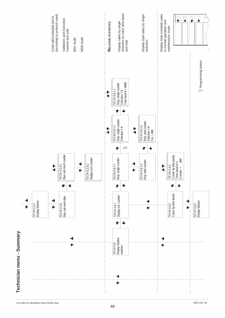
© by NECTA VENDING SOLUTIONS SpA 0401 216 -02
49
Pro
gram
min
g bu
tton
Tec
hn
icia
n m
enu
- S
um
mar
y
TEC
H>3
.3.3
Dis
play
failu
res
TEC
H>3
.3.4
Disp
. coin
mec
h da
ta
CO
IN M
EC
HA
NIS
M D
AT
A(a
ccor
ding
to
prot
ocol
use
d)
Val
idat
ors
and
Exe
cutiv
eC
ashe
d an
d so
ld
BD
V A
udit
MD
B A
udit
TEC
H>3
.3.4
.1Di
sp. c
oin
mec
h co
unte
r
TEC
H>3
.3.4
.2Di
splay
cas
h co
unte
r
Dis
play
sal
es b
y si
ngle
sele
ctio
n fo
r ea
ch t
ime
band
and
tota
l
Dis
play
tot
al s
ales
by
sing
lese
lect
ion
TEC
H>3
.4D
ispl
ay re
lativ
est
atis
tics
TEC
H>3
.4.1
Dis
play
sel
. cou
nter
TEC
H>3
.4.1
.1D
isp.
sin
gle
coun
ter
TEC
H>3
.4.1
.2D
isp.
tota
l cou
nter
TEC
H>3
.4.1
.1D
isp.
sin
gle
coun
ter
Sele
ctio
n 1-
#Ti
me
band
# =
###
#
TEC
H>3
.4.1
.1D
isp.
sin
gle
coun
ter
Sele
ctio
n 1-
#
TEC
H>3
.4.1
.2D
isp.
tota
l cou
nter
Sele
ctio
n 1-
#To
t. =
###
RE
LA
TIV
E S
TA
TIS
TIC
S
TEC
H>3
.4.2
Cou
nt. b
y tim
e ba
nds
TEC
H>3
.4.2
Cou
nt. b
y tim
e ba
nds
Tim
e ba
nd 0
÷4C
ount
er =
###
Dis
play
tot
al c
ompl
ete
sale
sin
nor
mal
ope
ratio
n an
dm
aint
enan
ce m
ode
TEC
H>3
.4.3
Dis
play
failu
res

© by NECTA VENDING SOLUTIONS SpA 0401 216 -02
50
Pro
gram
min
g bu
tton
Tec
hn
icia
n m
enu
- S
um
mar
y
TEC
H>3
.4.2
Cou
nt. b
y tim
e ba
nds
TEC
H>3
.4.3
Dis
play
failu
res
TEC
H>3
1.4.
3D
ispl
ay fa
ilure
sC
ompr
esso
rC
ount
er =
###
Mo
nit
ore
d f
ailu
res:
Com
pres
sor
Coi
n m
echa
nism
RA
M d
ata
Pro
beM
achi
ne c
ontr
ol b
oard
Gas
tem
pera
ture
sen
sor
Slid
er f
ailu
reS
lider
ope
nD
rum
fai
lure
TEC
H>3
.4.4
Disp
. coin
mec
h da
ta
CO
IN M
EC
HA
NIS
M D
AT
A(a
ccor
ding
to
prot
ocol
use
d)
Val
idat
ors
and
Exe
cutiv
eC
ashe
d an
d so
ld
BD
V A
udit
MD
B A
udit
TEC
H>3
.4.4
.1Di
sp. c
oin
mec
h co
unte
r
TEC
H>3
.4.4
.2Di
splay
cas
h co
unte
r
RE
LA
TIV
E S
TA
TIS
TIC
S
Del
ete
data
for
:S
elec
tions
Dis
coun
t/ove
rpric
eF
ailu
res
Coi
n m
echa
nism
dat
a
TEC
H>3
.5.1
.1D
elet
e pa
rtial
Sele
ctio
ns
TEC
H>3
.5.1
Del
ete
parti
alTE
CH
>3.5
Del
ete
stat
istic
s
ST
AT
IST
ICS
TEC
H>3
.5.1
.1D
elet
e pa
rtial
TEC
H>3
.5.1
.1D
elet
e pa
rtial
Con
firm
?Pr
intin
g...
TEC
H>3
.5.2
Del
ete
tota
lTE
CH
>3.5
.2.1
Del
ete
tota
lTE
CH
>3.5
.2.1
Del
ete
tota
l
Con
firm
?Pr
intin
g...

© by NECTA VENDING SOLUTIONS SpA 0401 216 -02
51
Pro
gram
min
g bu
tton
Tec
hn
icia
n m
enu
- S
um
mar
y
Del
ete
data
for
:S
elec
tions
Dis
coun
t/ove
rpric
eF
ailu
res
Coi
n m
echa
nism
dat
a
TEC
H>3
.6.1
.1D
elet
e pa
rtial
Sele
ctio
ns
TEC
H>3
6.1
Del
ete
parti
alTE
CH
>3.6
Del
ete
rela
tive
stat
istic
s
RE
LA
TIV
E S
TA
TIS
TIC
S
TEC
H>3
.6.1
.1D
elet
e pa
rtial
TEC
H>3
.6.1
.1D
elet
e pa
rtial
Con
firm
?Pr
intin
g...
TEC
H>3
.6.2
Del
ete
tota
lTE
CH
>3.6
.2.1
Del
ete
tota
lTE
CH
>3.6
.2.1
Del
ete
tota
l
Con
firm
?Pr
intin
g...
TEC
H >
3.7
Dis
. cou
nt .a
t sta
rt-up
Stat
usEn
able
d/di
sabl
ed
TEC
H >
3.7
Dis
play
cou
nter
at s
tart-
up
Enab
led
Dis
able
d
TEC
H >
4.1
Dru
m te
st
TEC
H >
4.2
Slid
er te
st
TEC
H >
4.1
Sele
ctdr
um#
TEC
H >
4.2
Sele
ctsl
ider
#
Pre
ss a
sel
ectio
n bu
tton
Pre
ss a
sel
ectio
n bu
tton
TEC
H >
4.3
Com
plet
e se
lect
ion
TEC
H >
4.3
Sele
ctdr
um#
Pre
ss a
sel
ectio
n bu
tton
TEC
H >
4Te
st

© by NECTA VENDING SOLUTIONS SpA 0401 216 -02
52
Pro
gram
min
g bu
tton
Tec
hn
icia
n m
enu
- S
um
mar
y
TEC
H >
5M
isce
llane
ous
TEC
H >
5.1
.1In
stal
latio
n da
teD
ate
=
XX.X
X.XX
TEC
H >
5.1
.1In
stal
latio
n da
te
Con
firm
?
Whe
n co
nfirm
ing,
the
cur
rent
date
will
be
set
as in
stal
latio
nda
te.
TEC
H >
5.1
Mac
hine
info
8-di
git
num
ber
iden
tifyi
ng t
hem
achi
ne.
TEC
H >
5.1
.2M
achi
ne c
ode
TEC
H >
5.1
.2M
achi
ne c
ode
Cod
e =
###
###
TEC
H >
5.1
.3O
pera
tor c
ode
TEC
H >
5.1
.3O
pera
tor c
ode
Cod
e =
###
##
6-di
git
num
ber
to id
entif
ygr
oups
of
vend
ing
mac
hine
s.
INIT
IAL
ISIN
G D
AT
AB
AS
ES
TEC
H >
5.2
Wor
king
...
TEC
H >
5.2
Con
firm
?
TEC
H >
5.2
Initi
alis
ing
dB S
TAR
T
# #
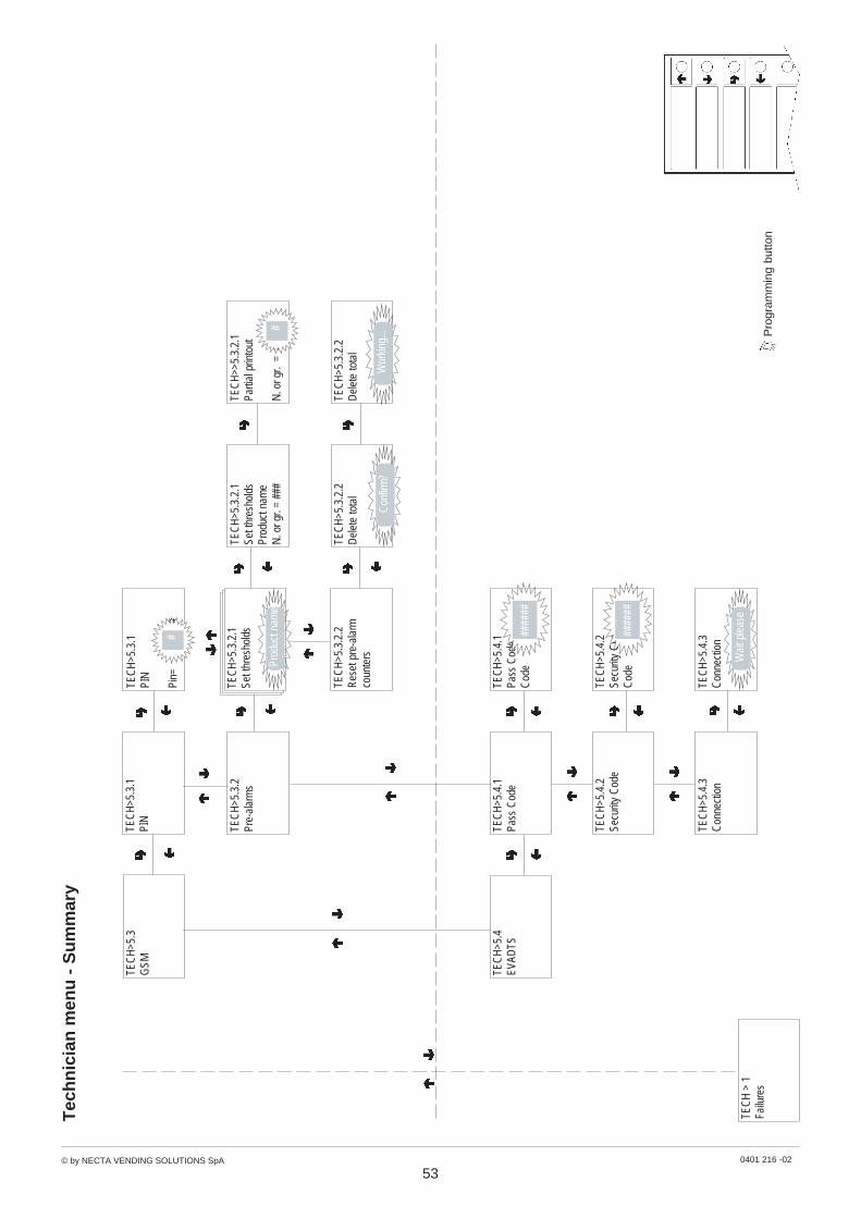
© by NECTA VENDING SOLUTIONS SpA 0401 216 -02
53
Pro
gram
min
g bu
tton
Tec
hn
icia
n m
enu
- S
um
mar
y
TEC
H>5
.3G
SM
TEC
H>5
.3.2
.2R
eset
pre
-ala
rmco
unte
rs
TEC
H>5
.3.2
.2D
elet
e to
tal
TEC
H>5
.3.2
.2D
elet
e to
tal
Con
firm
?W
orki
ng...
TEC
H>5
.3.2
Pre-
alar
ms
TEC
H>5
.3.1
PIN
TEC
H>5
.3.1
PIN
Pin=
##
###
#
TEC
H>5
.3.2
.1Se
t thr
esho
lds
Prod
uct n
ame
N. o
r gr.
= ##
#
TEC
H>>
5.3.
2.1
Parti
al p
rinto
ut
N. o
r gr.
= #
#
TEC
H>5
.3.2
.1Se
t thr
esho
lds
Prod
uct n
ame
#
TEC
H>5
.4EV
ADTS
TEC
H>5
.4.1
Pass
Cod
eTE
CH
>5.4
.1Pa
ss C
ode
Cod
e##
####
TEC
H>5
.4.2
Secu
rity
Cod
eTE
CH
>5.4
.2Se
curit
y C
ode
Cod
e##
####
TEC
H>5
.4.3
Con
nect
ion
TEC
H>5
.4.3
Con
nect
ion
Wai
t ple
ase
TEC
H >
1Fa
ilure
s
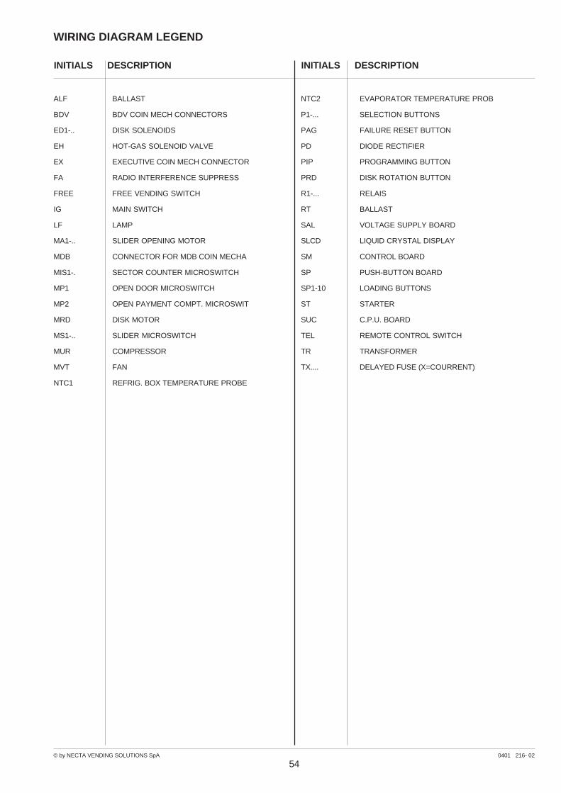
© by NECTA VENDING SOLUTIONS SpA 0401 216- 02
INITIALS DESCRIPTION
WIRING DIAGRAM LEGEND
INITIALS DESCRIPTION
54
ALF BALLAST
BDV BDV COIN MECH CONNECTORS
ED1-.. DISK SOLENOIDS
EH HOT-GAS SOLENOID VALVE
EX EXECUTIVE COIN MECH CONNECTOR
FA RADIO INTERFERENCE SUPPRESS
FREE FREE VENDING SWITCH
IG MAIN SWITCH
LF LAMP
MA1-.. SLIDER OPENING MOTOR
MDB CONNECTOR FOR MDB COIN MECHA
MIS1-. SECTOR COUNTER MICROSWITCH
MP1 OPEN DOOR MICROSWITCH
MP2 OPEN PAYMENT COMPT. MICROSWIT
MRD DISK MOTOR
MS1-.. SLIDER MICROSWITCH
MUR COMPRESSOR
MVT FAN
NTC1 REFRIG. BOX TEMPERATURE PROBE
NTC2 EVAPORATOR TEMPERATURE PROB
P1-... SELECTION BUTTONS
PAG FAILURE RESET BUTTON
PD DIODE RECTIFIER
PIP PROGRAMMING BUTTON
PRD DISK ROTATION BUTTON
R1-... RELAIS
RT BALLAST
SAL VOLTAGE SUPPLY BOARD
SLCD LIQUID CRYSTAL DISPLAY
SM CONTROL BOARD
SP PUSH-BUTTON BOARD
SP1-10 LOADING BUTTONS
ST STARTER
SUC C.P.U. BOARD
TEL REMOTE CONTROL SWITCH
TR TRANSFORMER
TX.... DELAYED FUSE (X=COURRENT)
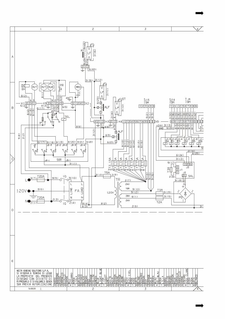
StarFoodUL 120 V
Sx38100
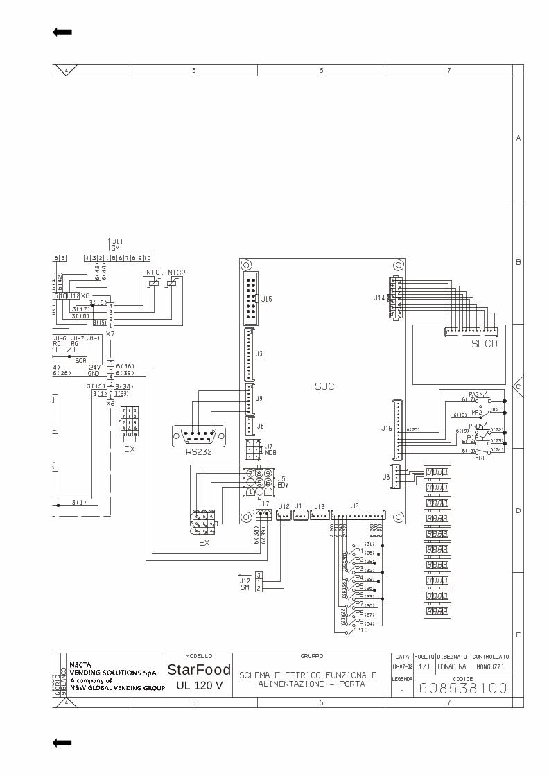
StarFoodUL 120 V
Sx38100

StarFood
Sx38200
UL 120 V
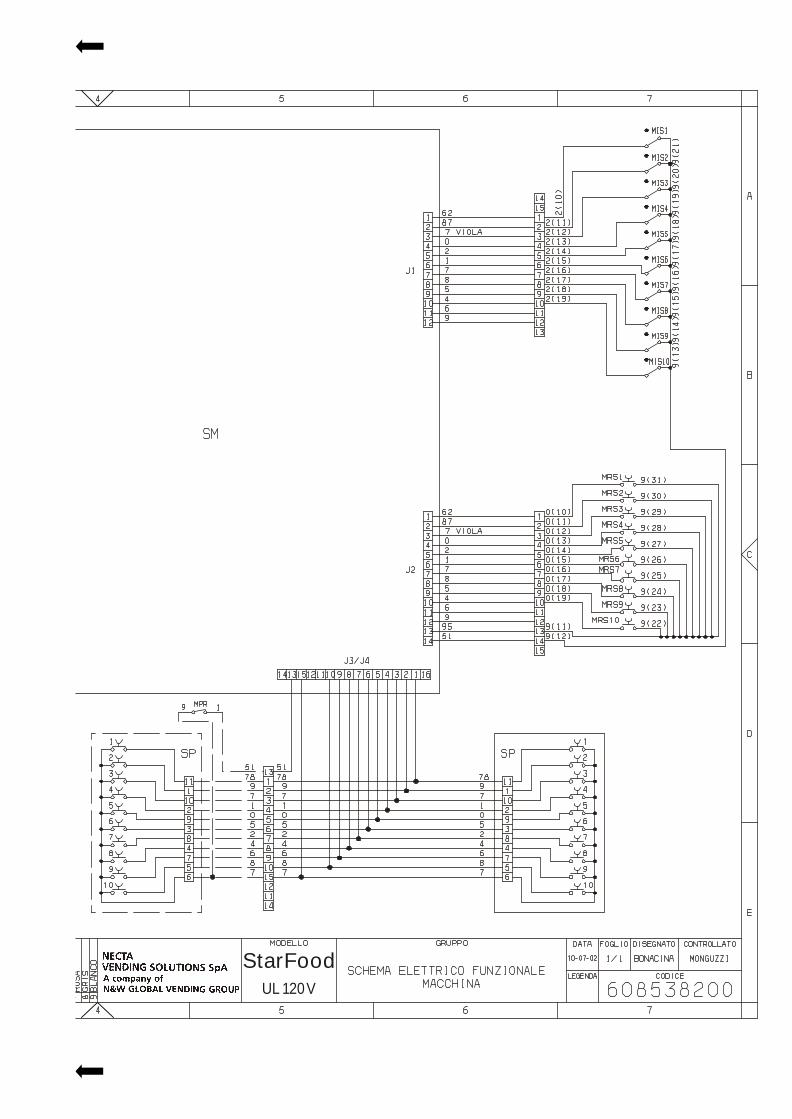
StarFood
Sx38200
UL 120 V
EDITION 04 01 CODE: H 216U 02
The Manufacturer reserves the right to modify, without prior notice, the characteristics of the equipment described in thispublication; and further declines to accept any responsibility for any inaccuracies contained in this publication which can beascribed to printing and/or transcription errors.All instructions, drawings, tables and information contained in this publication are confidential and can neither be repro-duced completely or in part, nor be transmitted to third parties without the written permit of the Manufacturer, who has thesole ownership.