stardom network
TRANSCRIPT

Technical Information TI 34P02K25-01E
STARDOM Network Configuration Guide
TI 34P02K25-01E3rd Edition Apr. 2006

Blank Page

i
All Rights Reserved. Copyright © 2002, Yokogawa Electric Corporation TI 34P02K25-01E Apr.20, 2006-00
Introduction
About This Document STARDOM system consists of autonomous controller FCNs/FCJs, field devices, VDS, HMI clients, and network devices, from which a user can select the optimum configuration. Components of STARDOM (FCN/FCJ, VDS, and HMI clients), with highly independent functions, are acquired through open technologies, allowing flexible configurations of devices. This document explains basic information needed for constructing networks of STARDOM system and detailed setting procedures along with specific cases.
Organization of This Document
Devices Overview This chapter explains the devices that configure STARDOM system.
STARDOM Network Functions This chapter explains basic network functions of STARDOM system.
Examples of Network Configurations This chapter explains setting procedures of the system through specific cases of network configurations.

Blank Page
Toc-1
TI 34P02K25-01E Apr.20, 2006-00
CONTENTS Introduction................................................................................................i 1. Devices Overview.............................................................................1
1.1 STARDOM Network Overview ................................................................... 1 1.2 Autonomous Controller FCN/FCJ............................................................. 4 1.3 VDS .............................................................................................................. 8 1.4 Network Devices....................................................................................... 10 1.5 Communication Protocols....................................................................... 17
2. Network Features of STARDOM....................................................19 2.1 Varieties of Basic Configurations........................................................... 19 2.2 Network Basic Definitions (IP Address Settings) ................................. 24 2.3 Communication Performances ............................................................... 33 2.4 Security ..................................................................................................... 43 2.5 Network Functions of FCN/FCJ .............................................................. 44 2.6 Duplexing Control Network..................................................................... 49 2.7 Cautions for Network Configuration ...................................................... 62
3. Examples of Network Configurations...........................................63 3.1 Small Two-layered System (Standard) ................................................... 63 3.2 Small One-layered System ...................................................................... 65 3.3 Medium Scale Two-layered System........................................................ 66 3.4 Installing Controllers in a Field as Standalone ..................................... 68 3.5 Connecting Simple HMI to Standalone Controller in a Field ............... 70 3.6 Connecting Routers to Control Networks ............................................. 73 3.7 Connecting Several Control Networks to VDS...................................... 75 3.8 Duplexing Networks................................................................................. 76 3.9 Connecting Devices (e.g.PLCs) Other than FCN/FCJ to VDS ............ 79 3.10 Connecting PLC to FCN/FCJ................................................................... 81 3.11 Operation with Remote HMI .................................................................... 85 3.12 Send Mails to/Receive Mails from VDS and FCN/FCJ ......................... 87 3.13 Monitoring and Maintaining FCN/FCJ Remotely................................... 89 3.14 Setting FCN/FCJ and VDS Remotely...................................................... 92 3.15 Connecting FCN/FCJ and VDS via WAN................................................ 93 3.16 Connecting Remote Devices to Duplexed Control Network............... 95 3.17 Synchronizing Times among Nodes ...................................................... 97
STARDOM Network Configuration Guide
TI 34P02K25-01E

Toc-2
TI 34P02K25-01E Apr.20, 2006-00
3.18 Using Hand-held Devices in a Field ..................................................... 103 3.19 Connecting Remote Sites Using Wireless Devices ............................ 105 3.20 Connecting to Existing ASTMAC.......................................................... 107
Revision Information .................................................................................i

<1. Devices Overview> 1
TI 34P02K25-01E Apr.20, 2006-00
1. Devices Overview This chapter explains the devices you need to take into consideration when constructing STARDOM system networks.
1.1 STARDOM Network Overview This section explains an example of basic network configuration of STARDOM system. STARDOM system consists of the following hardware:
Table Devices of STARDOM
Devices Contents
Controller FCN/FCJ, PLC, etc.
Data server VDS
HMI Devices with Web browser
Network device Hub, router, etc.
Field device Sensor, valve, contact I/O device, etc.
FCN FCJ
Control Network
PLC
VDS Data Server
HMI VDS
HMI Server
HMI
Firewall Router
Control System Information Network
Configuration PC
Field Device
Field Network
Information Network
Wide Area Network
HMI
HMI
Firewall Router
Field Device
Figure Basic Network Configuration
<1. Devices Overview> 2
TI 34P02K25-01E Apr.20, 2006-00
Control Network A control network is a Local Area Network (LAN) that connects controller devices such as autonomous controller FCNs/FCJs or PLCs, and VDS data servers. The reliability and real-time operation are required by this type of network that performs critical communications continuously over the network.
Field Network A field network is a small and slow network connecting FCNs/FCJs and intelligent filed devices or remote I/O devices. Typical examples are FF-H1, PROFIBUS, DEVICENET and Ethernet. FCNs/FCJs support FF-H1 and Ethernet in R1.11 and later.
Control System Information Network A control system information network is a LAN that connects VDS data servers, VDS HMI servers (commonly exist on the same PC with VDS data server) and HMI clients. On a small system, the level of control system information network can be submitted by connecting VDS HMI servers and HMI clients to control networks.
Information Network (Intranet) An information network is a backbone of intra-company information system LAN.
Wide Area Network (WAN, Internet) A WAN is a network that spans geographically dispersed area, such as public line or internet; a variety of network are available through public switched phone networks, leased lines, satellites, IP networks, etc.
FCN An FCN is a controller of the module mount type that is connected to control networks, with highly reliable features, allowing to duplex the control network, CPU, power supply and internal bus for connecting I/O module.
FCJ An FCJ is a small controller of the all-in-one type STARDOM that is connected to control networks, and can be installed in devices at sites. It is possible to duplex control networks. FCJ cannot be enhanced with I/O modules since it has a built-in I/O interface. In addition, it cannot duplex the CPU, power supply and internal bus for connecting I/O module. Other functions are same with FCN.
Field Devices (supporting field networks) These are intelligent field devices supporting field networks. These devices support FF-H1 and Ethernet.
PLC Other suppliers' PLCs supporting Ethernet communication can be connected to control networks.
VDS Data Server A VDS data server acquires control data from controllers on control networks, providing upper computer such as VDS HMI servers with abstracted data.

<1. Devices Overview> 3
TI 34P02K25-01E Apr.20, 2006-00
VDS HMI Server A PC equipped with Web-based HMI server functions. Normally, HMI servers and data servers run on the same PC. On some large scale systems, they can run on separate PCs.
HMI (HMI Client) An HMI is a Web-based HMI client device that provides operation and monitoring windows. A PC equipped with Internet Explorer and Java VM (Virtual Machine) is used.
Configuration PC A configuration PC is a PC that creates and downloads control logics of FCN/FCJ or field devices, and configures devices. You use this PC with installing configuration tools, to connect to control networks when starting up the system. You can install configuration tools on a PC on which VDS runs, to reduce the number of PCs. The configurations other than the basic network settings (IP addresses) of FCN/FCJ can be made from remote PCs connected via routers.
Table Main Configuration Tools
Tools Contents
Resource Configurator Configurations of FCN/FCJ
Logic Designer FCN/FCJ control logic design and download
Web browser Advanced configurations of FCN/FCJ
Graphic Designer Design of HMI operation and monitoring windows
Network Devices (Hub, Router, etc.) Components are connected to a hub, composing a star topology. When configuring separate network domains or connecting remote sites, you should construct networks via routers or firewalls. You need to choose the optimum devices according to the conditions of infrastructures in your area.
<1. Devices Overview> 4
TI 34P02K25-01E Apr.20, 2006-00
1.2 Autonomous Controller FCN/FCJ This chapter explains network interfaces of the autonomous controller FCN/FCJ. FCN/FCJ has two Ethernet network interfaces. Each interface has the number (1 or 2), and the label with the corresponding MAC address. If you do not duplex the control network, use only network interface1. Alternatively, they can be used as two separated networks. Each port is 10/100 Mbps, supporting full-duplex and auto negotiation functions.
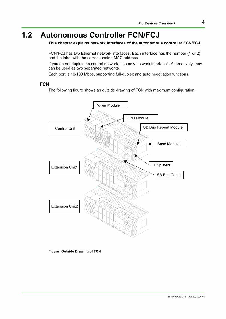
FCN The following figure shows an outside drawing of FCN with maximum configuration.
Control Unit
Extension Unit1
Extension Unit2
Power Module
CPU Module
SB Bus Repeat Module
T Splitters
SB Bus Cable
Base Module
Figure Outside Drawing of FCN

<1. Devices Overview> 5
TI 34P02K25-01E Apr.20, 2006-00
The network interface of FCN is installed on the front of the CPU module.
Display LED from left
RDY : Control program CTRL : Control Right
Reset Switch
Network Interface 1
Serial Port
Shutdown Switch
System Card Eject Button
System Card
MAC AddressCommunication Status LED from topLINK : Normal HUB connection statusACT : Send/Receive status
Network Interface 2
Figure CPU Module of FCN
Two network interfaces are installed; the above is 2 and the below is 1. Each MAC address is written on the side of the CPU module. The upper line indicates the MAC address of network interface1; the lower line is the MAC address of interface2.

<1. Devices Overview> 6
TI 34P02K25-01E Apr.20, 2006-00
FCJ
***********
Pressure Clamp Terminalfor Analog Input
FOUNDATIONFieldbus (H1)Signal Connection
Operating Status Display LEDHRDY : Normal hardware statusRDY : Normal system statusCTL : Normal control operation status
Pressure Clamp Terminalfor Digital Input
Pressure Clamp Terminalfor Digital Output
Pressure Clamp Terminalfor Analog Output
Figure Front Elevation of FCJ
Serial Port 2COM2
ResetSwitchSystem Card
Shutdown Switch
Network Interface(upper:2, lower:1)RJ45 Modular ConnectorCommunication Status LED LINK : Normal HUB connection status ACT : Send/Receive status
Pressure ClampTerminalfor Power Supply
Serial Port 1COM1
Figure Side View of FCJ from the Right

<1. Devices Overview> 7
TI 34P02K25-01E Apr.20, 2006-00
Two network interfaces are installed; the above is 2 and the below is 1. Each MAC address is written on the side of the CPU module. The upper line indicates the MAC address of network interface1; the lower line is the MAC address of interface2.
Devices that can be connected to FCN/FCJ The following devices can be connected. For communications on control applications, communication application portfolios corresponding to each device are required.
Table Devices that can be connected to FCN/FCJ
Types Devices Interfaces
Yokogawa Electric FA-M3 series Ethernet, RS-232-C PLC
Mitsubishi Electric MELSEC series Ethernet
Omron SYSMAC series RS-232-C, RS-422/RS-485
Power Monitor Yokogawa Electric power monitor RS-485
Temperature Controller Yokogawa Electric Green series RS-422/RS-485
Programmable Display Digital Co. GP-77 series TypeR, GP2000 series RS-232-C
Others Devices supporting MODBUS Ethernet, RS-232-C
For the detailed information on connecting devices, refer to instruction manuals or technical information published separately.

<1. Devices Overview> 8
TI 34P02K25-01E Apr.20, 2006-00
1.3 VDS This section explains the network interfaces of VDS. The network interface cards used on a PC on which VDS is implemented, can be general-purpose ones supporting Fast Ethernet. STARDOM realizes duplexed control networks by software; therefore, it is not required that you use the same suppliers' network cards for both of them.
TIP Some suppliers' network adapters provide duplexed networks by themselves with two identical network adapters mounted. However, you cannot use the supplier-provided duplex function for STARDOM control network.
Network Adapter Track Usage Records The following adapters were used for inspections of our products.
Table Track Usage Records of Network Adapters
Suppliers Adapters Models
3Com Fast EthernetLink XL PCI10-100 3C905B-J-TX
Intel EtherExpress Pro/100 Management PILA8460C3J

<1. Devices Overview> 9
TI 34P02K25-01E Apr.20, 2006-00
Devices that can be Connected to VDS Data Server The following devices can be connected to VDS Data server.
Table Devices that can be Connected to Data Server
Types Devices Interfaces Remarks
Yokogawa Electric FA-M3 series Ethernet, RS-232-C Standard
Mitsubishi Electric MELSEC series
Ethernet, Serial, MELSECNET II/ 10/H, CC-Link, etc.
Supporting Mitsubishi Electric middleware, "EZSocket"
Omron SYSMAC series (CPU unit:C/CV/CS1/FinsGateWay unit)
Ethernet, Serial, ControllerLink, SYSMACLINK, etc.
Supporting Omron middleware, "FinsGateWay"
Fuji Electric MICREX-F RS-232-C OPC server connection(*1)
Hitachi HIDEC-S10/2 α Ethernet OPC server connection(*1)
Sharp JW series Ethernet, RS-232-C OPC server connection(*1)
Matsushita Electric Works MEWNET-FP Ethernet, RS-232-C OPC server connection(*1)
KEYENCE KZ-A300/KZ-A500 RS-232-C OPC server connection(*1)
AB SLC series Ethernet OPC server connection(*1)
PLC
Siemens SIMATIC series Ethernet OPC server connection(*1)
Programmable Display Digital GP-77 series TypeR, GP2000 series Ethernet Digital middleware, "Pro
Server" is required
Power monitor Yokogawa Electric power monitor UZ005,PR201,UPM01/UPM02/UPM03/UPM100
RS-485
Thermometer Yokogawa Electric Green series RS-422/RS-485 Connected through FA-FM driver
Data acquisition Yokogawa Electric DARWIN series (DA100) Ethernet
Recorder Yokogawa Electric DAQSTATION (DX100/DX200/DX100P/DX200P) Ethernet
Others Options Options Created using VB *1: can be connected using an OPC server communication package.
<1. Devices Overview> 10
TI 34P02K25-01E Apr.20, 2006-00
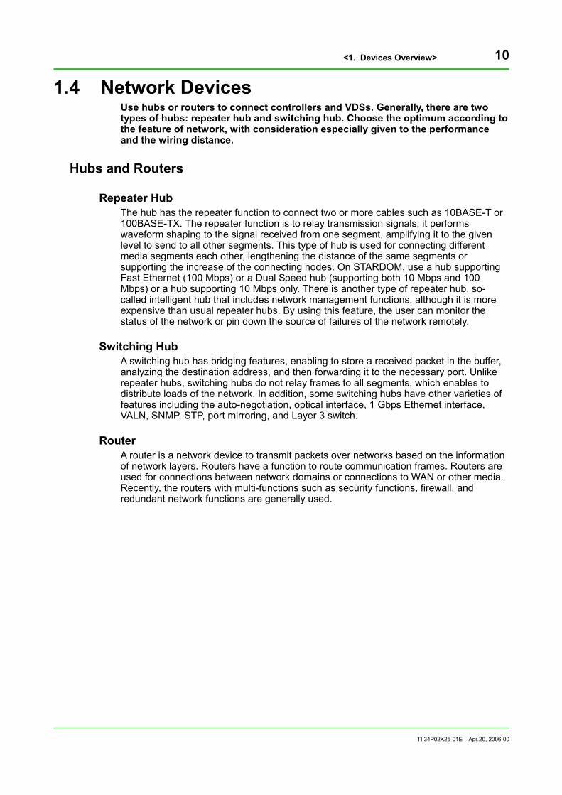
1.4 Network Devices Use hubs or routers to connect controllers and VDSs. Generally, there are two types of hubs: repeater hub and switching hub. Choose the optimum according to the feature of network, with consideration especially given to the performance and the wiring distance.
Hubs and Routers
Repeater Hub The hub has the repeater function to connect two or more cables such as 10BASE-T or 100BASE-TX. The repeater function is to relay transmission signals; it performs waveform shaping to the signal received from one segment, amplifying it to the given level to send to all other segments. This type of hub is used for connecting different media segments each other, lengthening the distance of the same segments or supporting the increase of the connecting nodes. On STARDOM, use a hub supporting Fast Ethernet (100 Mbps) or a Dual Speed hub (supporting both 10 Mbps and 100 Mbps) or a hub supporting 10 Mbps only. There is another type of repeater hub, so-called intelligent hub that includes network management functions, although it is more expensive than usual repeater hubs. By using this feature, the user can monitor the status of the network or pin down the source of failures of the network remotely.
Switching Hub A switching hub has bridging features, enabling to store a received packet in the buffer, analyzing the destination address, and then forwarding it to the necessary port. Unlike repeater hubs, switching hubs do not relay frames to all segments, which enables to distribute loads of the network. In addition, some switching hubs have other varieties of features including the auto-negotiation, optical interface, 1 Gbps Ethernet interface, VALN, SNMP, STP, port mirroring, and Layer 3 switch.
Router A router is a network device to transmit packets over networks based on the information of network layers. Routers have a function to route communication frames. Routers are used for connections between network domains or connections to WAN or other media. Recently, the routers with multi-functions such as security functions, firewall, and redundant network functions are generally used.
<1. Devices Overview> 11
TI 34P02K25-01E Apr.20, 2006-00
Main Functions of Network Devices This subsection explains the main functions and features of network devices for reference purposes to choose the optimum network device.
Full-Duplex Full-duplex enables the transmission of data in two directions simultaneously (send and receive), avoiding the collision of the two. With Fast Ethernet, 200 Mbps bandwidth is enabled.
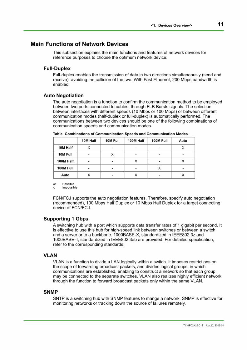
Auto Negotiation The auto negotiation is a function to confirm the communication method to be employed between two ports connected to cables, through FLB Bursts signals. The selection between interfaces with different speeds (10 Mbps or 100 Mbps) or between different communication modes (half-duplex or full-duplex) is automatically performed. The communications between two devices should be one of the following combinations of communication speeds and communication modes.
Table Combinations of Communication Speeds and Communication Modes
10M Half 10M Full 100M Half 100M Full Auto
10M Half X - - - X
10M Full - X - - -
100M Half - - X - X
100M Full - - - X -
Auto X - X - X X: Possible -: Impossible FCN/FCJ supports the auto negotiation features. Therefore, specify auto negotiation (recommended), 100 Mbps Half Duplex or 10 Mbps Half Duplex for a target connecting device of FCN/FCJ.
Supporting 1 Gbps A switching hub with a port which supports data transfer rates of 1 gigabit per second. It is effective to use this hub for high-speed link between switches or between a switch and a server or to a backbone. 1000BASE-X, standardized in IEEE802.3z and 1000BASE-T, standardized in IEEE802.3ab are provided. For detailed specification, refer to the corresponding standards.
VLAN VLAN is a function to divide a LAN logically within a switch. It imposes restrictions on the scope of forwarding broadcast packets, and divides logical groups, in which communications are established, enabling to construct a network so that each group may be connected to the separate switches. VLAN also realizes highly efficient network through the function to forward broadcast packets only within the same VLAN.
SNMP SNTP is a switching hub with SNMP features to mange a network. SNMP is effective for monitoring networks or tracking down the source of failures remotely.

<1. Devices Overview> 12
TI 34P02K25-01E Apr.20, 2006-00
Layer3 Switch Layer3 switch is a switching hub with routing functions implemented in the hardware. Faster routing operations and relatively reasonable prices than usual routers are attained in this switching hub.

<1. Devices Overview> 13
TI 34P02K25-01E Apr.20, 2006-00
Track Usage Record of Network Devices
Track Usage Record of Hubs The following products were used for labo test of STARDOM.
Table Track Usage Record of Hubs
Manufacturers Product names/type names Remarks
Cisco Catalyst2912/24 XL-EN Switching hub with management features
Cisco Catalyst2950-24 Switching hub with management features
3Com SuperStack 3 Switch 3300SM 3C16985 Switching hub with management features
3Com Office connect Dual Speed Hub 8 Dual speed hub
Allied Telesis CentreCOM FS708XL Switching hub
Allied Telesis CentreCOM FS708EXL Switching hub
HP ProCurve Switch 2512/2524 Switching hub,0-55 °C
TIP • It takes several tens of seconds for switching hubs with management features to start a packet relay
operation, because the initialization processing is generally carried out after they are turned on. Therefore, if an FCN with duplexed CPUs is connected to such a switching hub and if the FCN and the switching hub are turned on simultaneously, the APC (All Program Copy) processing may fail when the FCN is turned on. In this case, turn on the switching hub first. After the initialization processing of the switching hub is finished, turn on the FCN.
• By default, the spanning tree protocol (a function to automatically set usual routes or routes when making detours in networks with multiple routes) is configured to Cisco’s switching hubs. In this case, hubs do not forward data to relevant ports for about 30 seconds after devices connected to the hubs were turned on. In order to avoid this problem, cancel the configuration for using the spanning tree protocol.
Track Usage Record of Routers The following products were used for labo test of STARDOM.
Table Track Usage Record of Routers
Manufacturers Product names/type names Remarks
YAMAHA RT140f VPN, firewall features
Allied Telesis CentreCOM AR320 Firewall features
Hubs for Industrial Environments For reference purposes, hubs used for industrial environments on the market are listed below; however, they are not used for labo test of STARDOM.
Table Hubs used for Industrial Environments
Manufacturers Product names/type names Remarks
Hirchmann RS2-TX 8 Port, 10/100Base-Tx, 24 VDC, 0-60 °C
Phoenix Contact FL HUB 10BASE-T 10BaseT, 24 VDC, 0-55 °C
CONTEC SH-8008L 8 Port, 10/100Base-Tx, 100Vac, 0-55 °C

<1. Devices Overview> 14
TI 34P02K25-01E Apr.20, 2006-00
Cables Please avoid unplugging cables attached to a device by fixing it to a rack or other furniture, or taking other measures. Generally used LAN cables are listed as follows.
UTP Cables A UTP cable is the most commonly used unshielded twisted pair cable. Use category 5 or higher UTP cables. There are 4-conductor cables and 8-conductor cables; the both type can be used. Make a choice between a cross cable and straight cable according to the intended purpose. Generally, a straight cable is used when the connection is made between a node and a hub; a cross cable is used when the connections are made between only hubs or only nodes. Refer to the manual of each network device because the specification may differ by the device. Select generally used RJ-45 type plugs for the connectors of both ends.
STP Cables In environments with much noise, use shielded twisted pair (STP) to reduce the effects of noise. However, conditions of usage may differ by the network device; use the cable on your own authority referring to the manual of the network device in use.
Optical Fiber Cables It is recommended to use this type of cable when you lengthen distances, wire between separate buildings or use the device in the environment with much noise. The following LAN standards are provided for the use of optical fiber cables: 10BASE-FL, 100BASE-FX, 1000BASE-SX and 1000BASE-LX. Each standard defines the type of optical fiber and maximum distances. For the detailed specification, refer to manuals of the network device in use or manuals of IEEE802 or the standard itself. Media converters having optical interfaces or switching hubs supporting optical interfaces are needed because optical interfaces have not been mounted on FCNs/FCJs.
Specifications of Major Cables Specifications of major network cables are shown below.
Table Specifications of Major Network Cables
Standard Bandwidth Cable Maximum Distance Remarks
10BASE-T 10 Mbps UTP (Category 3) 100 m Copper cable of 10 Mbps
100BASE-TX 100 Mbps UTP (Category 5) STP (Type 1, 2) 100 m Copper cable of
100 Mbps
100BASE-FX 100 Mbps GI/MMF wavelength 1300 nm 62.5/125 μm
412 m (half duplex) 2000 m (full duplex)
Optical fiber cables of 100 Mbps

<1. Devices Overview> 15
TI 34P02K25-01E Apr.20, 2006-00
Installing Network Devices
Power Dispatching When the power of one of network devices such as a hub is shut down, the entire communications of all devices attached to the network device stop. You should determine the power routing considering the scope of effects as described above. In the case where the reliability is severely required, it is recommended to prepare backup powers, or duplex network devices, each of which be powered via separate routing.
Selecting Devices As far as possible, install network devices including a hub for each area, with minimum number of wirings among the area. Choose network devices according to the purpose, among several types e.g., devices for mounting to a 19-inch rack, to a desktop or to a wall. For the number of ports, it is recommended to choose a hub with more ports than you actually use at present, in consideration of the future expansion or the use as a port for monitoring when failures will occur. According to the environment (temperature, moisture, dust, noise, etc.) where the network device is installed, select the optimum one.
Checking LED Display LEDs for checking statuses are implemented on each network interface of FCN/FCJ. Generally, LEDs are also implemented on ports of network adapters and network devices. When finished connecting the cable, you need to check if the Link light flashes, and Act, Send, Rcv and other lights flash while communication is performed.
Table Network Interface LEDs of FCN/FCJ
Colors Names Contents
Yellow LINK Connection is normal
Orange ACT Send/receive
For the LED displays of hubs or network adapters, refer to the manual of each device since the number and role of each LED differ by the device.
Communication Test When you finished setting the device and connections, check if the communication is normally established by executing Ping command or other methods.
Replacing Network Devices You can replace network devices such as hubs, cables or routers on-line. The communication stops while the device is replaced; however, it starts again when you connect the cable after the replacement. If the control network is duplexed, the network has the feature to switch communication paths automatically, enabling to change the device maintaining the communication. Please follow the right steps to change the device checking the messages notifying the failure or the recovery of the network.

<1. Devices Overview> 16
TI 34P02K25-01E Apr.20, 2006-00
Restrictions on total distances of networks According to the 100BASE-T/10BASE-T standards, cables of up to 100 meters can be used. It is possible to extend the total distance via hubs on many levels with cascade connections. However, if a repeater hub is used, the following restrictions are applied to total distances: • If a repeater hub is used with 10BASE-T cables: The total distance is up to 500 meters, with up to 4 levels in cascade connections
and within 100 meters for cable lengths between devices. • If a repeater hub is used with 100BASE-T cables The total distance is up to 205 meters, with up to 2 levels in cascade connections,
within 100 meters for cable lengths between devices and within 5 meters for cable length between hubs (IEEE802.3u Standard).
If a network requires a total distance exceeding these restrictions, use switching hubs or routers to configure such a network.
<1. Devices Overview> 17
TI 34P02K25-01E Apr.20, 2006-00
1.5 Communication Protocols This chapter explains the communication protocols used in the devices that configure STARDOM system. STARDOM system uses Ethernet for control networks and the upper control system information network. For network layers and transport layers, the industry-standard TCP/IP is employed.
Communications between VDS Data Server and FCN/FCJ For communications between VDS data server and FCN/FCJ, a communication protocol based on Fast Ethernet and TCP/IP is employed.
Time Synchronization FCN/FCJ has SNTP client functions and time adjusting functions as standard features, enabling to synchronize times among nodes. In addition, it is possibe to operate the SNTP server feature by installing a time synchronization server portfolio in the FCN/FCJ.
Utility Communications Configuration tools for defining FCN/FCJ or field network devices and designing control logics, establish communications with FCN/FCJ using dedicated protocols. More specifically, the tools download definitions of devices defined on Resource Configurator or other configuration tools, download control logics created on Logic Designer, and execute maintenance communications of control logics using Logic Designer.
Communications between VDS Data Server and VDS HMI Server OPC-DA is employed for communications between VDS data server and VDS HMI server, or VDS data server and other computers.
Communications between VDS HMI Server and HMI Client HMI client does not require any software other than Web browsers. For communications between HMI and VDS HMI server, HTTP used by a Web browser is employed.
Network Features of FCN/FCJ FCN/FCJ normally supports the protocols needed to communicate with open network devices: receiving and sending mails, HTTP, FTP, TELNET, and other protocols.

Blank Page

<2. Network Features of STARDOM> 19
TI 34P02K25-01E Apr.20, 2006-00
2. Network Features of STARDOM This chapter explains basic network features of STARDOM system.
2.1 Varieties of Basic Configurations Several examples of basic network configurations are shown in this section.
Small Two-layered System (Standard) In this type of network, the control system information network connecting HMI clients and the broadcast domain of the control network connecting controllers are separately configured. This is one of the standard system configurations of STARDOM. Generally, two network adapters are mounted on a VDS data server; one is used for control network, and the other is used for control system information network.
FCN FCN FCJ
VDS Data Server HMI Server
PLC
Control Network (Up to 126 controllers)
HMI HMI
Control System Information Network
Upper Computer
(Up to 4 VDSs)
(Up to 32 controllers per VDS)
Figure Small Two-layered System
Restrictions on Implementation • The maximum node number connected to a control network: 126 • The maximum number of controllers including FCN/FCJ and PLC connected to a
single data server: 32 • The maximum number of VDS data servers connected to a control network: 4 • The maximum HMI clients (sessions) connected to a single VDS HMI server: 50 • There are no restrictions on total distances of the network.

<2. Network Features of STARDOM> 20
TI 34P02K25-01E Apr.20, 2006-00
• Routing of communication frames is needed if a control system information network directly communicate to devices on a control network. For routing, use VDS as a router or set a local router between the control system information network and the control network. In consideration of the features of a control network, performing real-time and reliable communications, you should not include frames unnecessary for the network by routing.
SEE ALSO • For the maximum number of data objects and data points upon per VDS data server, see "2.3
Communication Performances".
• For IP address settings on a small two-layered system, see "3.1 Small Two-layered System (Standard)".
• For examples of configuration with routing, see "3.6 Connecting Routers to Control Networks".

<2. Network Features of STARDOM> 21
TI 34P02K25-01E Apr.20, 2006-00
Small One-layered System On a small system, HMI clients can be connected to a control network when there is no need to configure a control network and a control information network separately. In this case, one network adapter mounted on a VDS is sufficient.
FCN FCN FCJ
VDS Data Server HMI Server HMI Client
PLC
Control Network (up to 126 devices)
HMI HMI (Up to 4 VDSs)
(Up to 32 controllers upon a VDS)
Figure Small One-layered System
SEE ALSO • For restrictions on implementation, see "Small Two-layered System (Standard)" in this section.
• For IP address settings on a small one-layered system, see "3.2 Small One-layered System".

<2. Network Features of STARDOM> 22
TI 34P02K25-01E Apr.20, 2006-00
Medium Scale Two-layered System This medium scale system consists of several VDSs. A VDS HMI server collects and consolidates data from VDS data servers, giving these data to HMI clients. You can implement VDS HMI data server functions on one of VDS data servers. In the following cases, it is recommended to connect several VDS data servers. • Many controllers to be connected • Many data points • Controllers are distributed in remote areas
FCN FCN FCJ
VDS Data Server
Control Network1
Upper Computer HMI
Control System Information Network
VDS HMI Server
...
FCN FCN FCJ
VDS Data Server
Control Network2
...
HMI
(Up to 4 VDS data servers)
Figure Medium Scale Two-layered System
Restrictions on Implementation • The maximum number of VDS data servers connected to a single VDS HMI data
server: 4
SEE ALSO • For other restrictions on the implementation, see "Small Two-layered System (Standard)".
• For the number of maximum data objects and data points upon a single VDS HMI data server, see "2.3 Communication Performances".
• For IP address settings on a medium scale two-layered system, see "3.3 Medium Scale Two-layered System".

<2. Network Features of STARDOM> 23
TI 34P02K25-01E Apr.20, 2006-00
Three-layered System (Remote Operations) For example, this network configuration may contain remotely installed HMI clients (e.g. in offices) monitored via intra-company information network (e.g. intranet). For the purpose of improving securities, routers or other devices are connected between the information network and the control system information network.
FCN FCN FCJ
VDS Data
Server
PLC
Control Network
HMI HMI
Control System Information Network
VDS HMI Server
VDS Data
Server
Router
...
... ...
Remote Area
Information Network Router
Figure Three-layered System
SEE ALSO For restrictions on implementation, see "Small Two-layered System (Standard)" and "Medium Scale Two-layered System".

<2. Network Features of STARDOM> 24
TI 34P02K25-01E Apr.20, 2006-00
2.2 Network Basic Definitions (IP Address Settings) This section explains IP address settings of FCN/FCJ and VDS connected to control networks of STARDOM.
Rules for IP Address Allocation STARDOM’s control networks can take two types of configurations: single and duplex. Moreover, CPUs can be duplexed in the FCN, where an IP address is allocated to each of the duplexed CPUs. The rules for IP address allocation in each configuration are described below:
Single Network Configuration [If the FCN does not use a configuration of duplexed CPUs] There are no restrictions on the IP addresses that can be used. [If the FCN uses a configuration of duplexed CPUs] Arbitrary IP addresses can be set to both the control side CPU and the standby side CPU of the FCN. Use the Resource Configurator and specify an IP address for the control side CPU. Then, select the “Detail…” button of the “General” tab under “CPU Module”, remove the tick for “Auto” in the IP address checkbox for the standby side CPU, and explicitly specify an IP address for the standby-side CPU.
TIP • If there are multiple control system network domains, change the respective network addesses.
e.g.
Domain 1: 192.168.0.0
Domain 2: 192.168.1.0
• When the FCN has duplexed CPUs, the IP address of the standby side CPU is, by default, automatically allocated on the basis of the IP address of the control side CPU according to certain rules as explained in the “IP Address Decision Rules” section in “2.6 Duplexing Control Network” Therefore, if the default IP address of the standby side CPU is used as it is, specify a value for the IP address of the control side CPU in such a way that the value will not contradict the IP address of the standby side CPU.
In a single network configuration, the default value for the IP address of the standby side CPU can be changed by the Resource Configurator. Therefore, if you wish to designate an arbitrary IP address for the control side CPU, change the default value for the IP address of the standby side CPU, too.

<2. Network Features of STARDOM> 25
TI 34P02K25-01E Apr.20, 2006-00
Duplexed Network Configuration [If the FCN does not use a configuration of duplexed CPUs] It is recommended to use class C private addresses of IPv4. The setting procedures of IP addresses are explained as follows: • Set an address in the range of 192.168.x.1-192.168.x.254, in which “x” is a multiple
of 3 in the range of 0-252. • Set a subnet mask to 255.255.255.0. • Specify the address of a default router connected to the control network for the
default gateway. If you do not connect a router to the control network, it is not needed to specify the address.
• Example of IP address settings IP address: 192.168.3.1
Subnet mask: 255.255.255.0
Default gateway: none
This setting reserves 192.168.4.1 and 192.168.5.1 as IP addresses. [If the FCN uses a configuration of duplexed CPUs] Basically, use IP addresses according to the same rule as in the case of not using a configuration of duplexed CPUs. However, IP addresses must be within the range of 192.168.x.1 – 192.168.x.126 so that no contradiction will occur in the automatic IP address allocation for the standby side CPU of the FCN to be described later. In this case, an IP address for the standby side CPU will fall within the range of 192.168.x.129 – 192.168.x.254.
TIP • When several network domains exist, different addresses should be set to each of them.
e.g. Domain 1: 192.168.0.0
Domain 2: 192.168.3.0
• IP addresses with X other than multiples of 3 are automatically used as physical IP addresses (PIP-A and PIP-B).
• It is recommended to define each IP address allocation depending on the device; for example, the controller begins from 192.168.x.1 and the VDS begins from 192.168.x.101, etc.
• If you set IP addresses other than those of Class C, read the “IP Address Decision Rules” section in “2.6 Duplexing Control Network” and set the IP addresses for automatic allocation in such a way that they will not be the same as the IP addresses of other devices. Notice that, in a duplexed network, automatically allocated IP addresses cannot be changed with respect to both IP addresses for PIP-A and PIP-B or the IP address for the standby side CPU.
• The FCN/FCJ allows a configuration of separated networks (in which two network ports are used as separate networks). However, in this network configuration, use the same concept as in the case of a single network to decide IP addresses.

<2. Network Features of STARDOM> 26
TI 34P02K25-01E Apr.20, 2006-00
Network Configuration of the FCN/FCJ The FCN/FCJ has two network ports per CPU. These ports can take the following three network configurations: • Single network configuration (in which network port 2 is not used) • Duplexed network configuration • Separated network configuration (connected to two separated networks)
Each configuration is set in the “Network Group” combo box of the “Basic Configuration” tab in the CPU Module Setting window of the Resource Configurator. The overview of how each network configuration works is described below:
Single Network Configuration A single network is configured as follows:
VDS
Control Network Subnet mask 255.255.255.0
FCN/FCJ Single CPU
FCN FCN duplexed CPU
192.168.0.101
192.168.0.1 192.168.0.2 192.168.0.130
Router
Network for PLC Subnet mask 255.255.255.0
PLC1 PLC2
192.168.20.1 192.168.20.2
192.168.0.124
192.168.20.124
Figure Example of a Single Network Configuration
If control right is alternated when CPUs are duplexed in the FCN, IP addresses are changed as follows:
FCN (standby)
1
2
FCN (control)
1
2
192.168.0.130192.168.0.2
Without IP
Alternation of Control
FCN (control)
1
2
FCN (stop)
1
2
192.168.0.2
FCN (control)
1
2
FCN (standby)
1
2
192.168.0.2 192.168.0.130
APC
Without IP
Without IP
Without IP
Without IP
Without IP
Without IP
Figure Operations when Control Right is Alternated in a Single Network Configuration

<2. Network Features of STARDOM> 27
TI 34P02K25-01E Apr.20, 2006-00
Duplexed Network Configuration A duplexed network is configured as follows:
VDS
Control Network Subnet mask 255.255.255.0 VIP (NetAdr): 192.168.0.0
FCN/FCJ Single CPU
FCN FCN duplexed CPU
192.168.0.101 (VIP)
192.168.0.1 (VIP) 192.168.0.2 (VIP)
PIP-B (NetAdr):192.168.2.0
192.168.1.101 192.168.2.101
192.168.1.1 192.168.2.1 192.168.1.2
192.168.2.2 192.168.1.130
192.168.2.130
Control System Information Network Subnet mask 255.255.0.0 172.16.1.64
PC
172.16.1.21
PIP-A (NetAdr):192.168.1.0
NetAdr: Network Address
Figure Example of a Duplexed Network Configuration
If control right is alternated when CPUs are duplexed in the FCN, IP addresses are changed as follows:
192.168.0.2 (VIP)
192.168.1.2 (PIP-A)
Alternation of Control
192.168.0.2 (VIP)
APC
Without IP
192.168.1.130 (PIP-A)
192.168.2.130 (PIP-B) 192.168.2.2 (PIP-B)
192.168.1.130 (PIP-A)
192.168.2.130 (PIP-B)
PIP on the left remains as it is.
192.168.0.2 (VIP)
192.168.1.130 (PIP-A)
192.168.2.130 (PIP-B)
192.168.1.2 (PIP-A)
192.168.2.2 (PIP-B)
PIP on the rightremains as it is.
Without IP
FCN (standby)
1
2
FCN (control)
1
2
FCN (control)
1
2
FCN (stop)
1
2
FCN (control)
1
2
FCN (standby)
1
2
Figure Operations when Control Right is Alternated in a Duplexed Network Configuration
TIP VIP means a virtual IP address. PIP-A and PIP-B mean physical IP address A and physical IP address B respectively. For details, see “Various IP Addresses” in “2.6 Duplexing Control Network”

<2. Network Features of STARDOM> 28
TI 34P02K25-01E Apr.20, 2006-00
Separated Network Configuration In a separated network configuration, port 1 of the FCN/FCJ is used for a control network, while port 2 is used for a network independent of the control network: for example, it is connected to a network dedicated to PLC, in which one port is used for PLC communications. However, when connecting PLCs or PCs to the FCN/FCJ via a network, the network must be configured to avoid having influences on FCN/FCJ control by communication load lead from other devices.
SEE ALSO Refer to “2.7 Cautions for Network Configuration” when connecting devices other than VDS and FCN/FCJ devices to the network.
This network configuration has the following restrictions: • No routing can be performed between port 1 and port 2. • With respect to FCN/FCJ communications using the communication function block,
port 1 allows communications via routers (communications to separate subnets), while port 2 does not.
Separated networks are configured as follows:
192.168.20.1
VDS
Control network Subnet mask 255.255.255.0
FCN/FCJ Single CPU
FCN FCN Duplexed CPU
192.168.0.101
192.168.0.1 192.168.0.130
Control system information networkSubnet mask 255.255.0.0 172.16.1.1
PC
172.16.1.21
PLC1 PLC2 PLC3 PLC4
192.168.20.3
192.168.20.2 192.168.40.1 192.168.40.2
192.168.40.3 192.168.40.131
Router
PLC5
192.168.60.1
192.168.40.124
192.168.60.124
192.168.0.2
Network 2 dedicated to PLCSubnet mask
255.255.255.0
Network 3 dedicated to PLCSubnet mask
255.255.255.0
Network 1 dedicated to PLC Subnet mask
255.255.255.0
Figure Example of a Separated Network Configuration

<2. Network Features of STARDOM> 29
TI 34P02K25-01E Apr.20, 2006-00
If control right is alternated when CPUs are duplexed in the FCN, IP addresses are changed as follows:
FCN
(standby)
1
2
FCN (control)
1
2
192.168.0.130 192.168.0.2
192.168.40.131
Alternation of Control
FCN (control)
1
2
FCN (stop)
1
2 192.168.40.3
Without IP 192.168.0.2
Without IP
FCN (control)
1
2
FCN (standby)
1
2 192.168.40.131
192.168.0.2 192.168.0.130
APC
192.168.40.3
192.168.40.3
Figure Operations when Control Right is Alternated in a Separated Network Configuration
<2. Network Features of STARDOM> 30
TI 34P02K25-01E Apr.20, 2006-00
IP Address Settings to FCN/FCJ You can configure IP addresses to an FCN/FCJ on Resource Configurator as follows: 1. Connect a PC on which Resource Configurator is installed to FCN/FCJ, and start
Resource Configurator on the PC. Resource Configurator and FCN/FCJ must be connected on the same broadcast domain. The IP addresses cannot be set via a router.
2. To the network interface1 of FCN/FCJ, connect an Ethernet cable. IP addresses
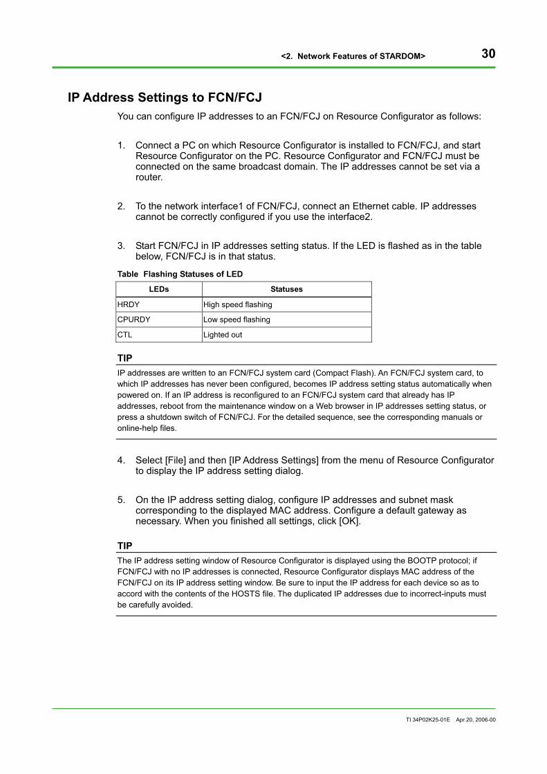
cannot be correctly configured if you use the interface2. 3. Start FCN/FCJ in IP addresses setting status. If the LED is flashed as in the table
below, FCN/FCJ is in that status.
Table Flashing Statuses of LED
LEDs Statuses
HRDY High speed flashing
CPURDY Low speed flashing
CTL Lighted out
TIP IP addresses are written to an FCN/FCJ system card (Compact Flash). An FCN/FCJ system card, to which IP addresses has never been configured, becomes IP address setting status automatically when powered on. If an IP address is reconfigured to an FCN/FCJ system card that already has IP addresses, reboot from the maintenance window on a Web browser in IP addresses setting status, or press a shutdown switch of FCN/FCJ. For the detailed sequence, see the corresponding manuals or online-help files.
4. Select [File] and then [IP Address Settings] from the menu of Resource Configurator
to display the IP address setting dialog. 5. On the IP address setting dialog, configure IP addresses and subnet mask
corresponding to the displayed MAC address. Configure a default gateway as necessary. When you finished all settings, click [OK].
TIP The IP address setting window of Resource Configurator is displayed using the BOOTP protocol; if FCN/FCJ with no IP addresses is connected, Resource Configurator displays MAC address of the FCN/FCJ on its IP address setting window. Be sure to input the IP address for each device so as to accord with the contents of the HOSTS file. The duplicated IP addresses due to incorrect-inputs must be carefully avoided.

<2. Network Features of STARDOM> 31
TI 34P02K25-01E Apr.20, 2006-00
With these settings, the IP address settings of the single control network configuration have been completed. If you are to have the duplexed or separated control network configuration, perform the following settings: 6. Use the Resource Configurator to connect to the FCN/FCJ and configure a control
network. For detailed operation methods, see the “Network functions” section on the [FCN/FCJ Setting] – [CPU Module Setting] page of the Resource Configurator’s online help and set a duplexed or separated network configuration.
IP Address Settings to VDS You will set IP addresses to a PC onto which you will mount functions of VDS (VDS data server, VDS HMI server, and HMI client). Configure the same network addresses of FCN/FCJ to the network interface of VDS data server connected to the control network. If you do not use the duplexed control network function, configure the IP addresses according to the Windows standard procedures.
VIP (Virtual IP Address) Settings If you use the duplexed control network function, you need to start FCN/FCJ connection setting tool to configure virtual IP addresses (VIP).
SEE ALSO For settings of the duplexed control network function and VIP, see "2.6 Duplexing Control Network".
<2. Network Features of STARDOM> 32
TI 34P02K25-01E Apr.20, 2006-00
Creating HOSTS Files The correspondences between IP addresses connected to a control network and host names are managed in HOSTS files. The HOSTS files are referred for host name resolution while communicating, or IP address settings of FCN/FCJ on Resource Configurator.
TIP HOSTS files are used for managing each node with the logical name. If you set nodes to be managed with only IP addresses, it is possible to omit the procedure to create HOSTS files.
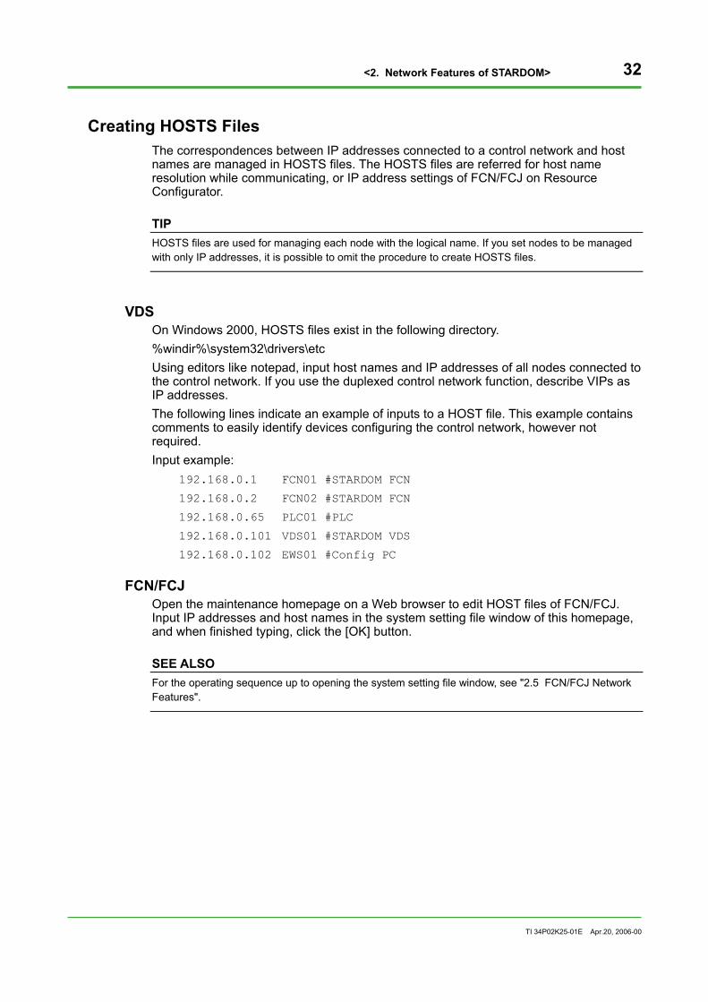
VDS On Windows 2000, HOSTS files exist in the following directory. %windir%\system32\drivers\etc Using editors like notepad, input host names and IP addresses of all nodes connected to the control network. If you use the duplexed control network function, describe VIPs as IP addresses. The following lines indicate an example of inputs to a HOST file. This example contains comments to easily identify devices configuring the control network, however not required. Input example:
192.168.0.1 FCN01 #STARDOM FCN
192.168.0.2 FCN02 #STARDOM FCN
192.168.0.65 PLC01 #PLC
192.168.0.101 VDS01 #STARDOM VDS
192.168.0.102 EWS01 #Config PC
FCN/FCJ Open the maintenance homepage on a Web browser to edit HOST files of FCN/FCJ. Input IP addresses and host names in the system setting file window of this homepage, and when finished typing, click the [OK] button.
SEE ALSO For the operating sequence up to opening the system setting file window, see "2.5 FCN/FCJ Network Features".

<2. Network Features of STARDOM> 33
TI 34P02K25-01E Apr.20, 2006-00
2.3 Communication Performances A STARDOM system collects and monitors data from controllers via networks. Therefore, it is important to estimate communication performances of the network. This chapter details the approximate scale of a standard STARDOM system and how to estimate communication loads.
Standard System Scale The approximate calculation of data (data object number, data point number) and communication time (data acquisition time, starting time) are indicated in the table below:
Table Approximate Traffic
Types Items Specifications
Amount of data per FCN/FCJ At most 3200 points/sec
Data number per VDS data server At most 400 objects/sec, At most 6400 points/sec
Communication time per object (accessing a single object, 100 Mbps) At most 50 ms
VDS data server and FCN/FCJ
Communication time per 100 objects (accessing several objects, 100 Mbps) At most 400 ms
Amount of data per VDS data server At most 400 objects/sec, At most 6400 points/sec
Amount of data per VDS HMI server At most 1600 objects/sec, At most 25600 points/sec
VDS data server and VDS HMI server
Communication time per object 100 ms or less
HMI clients per VDS HMI server At most 50 clients VDS HMI server and HMI client Communication time per object 100 ms or less
Necessity of Network Load Calculation It is necessary to calculate network load factor accurately when you construct a large-scale system or employ low band including wide area network as the communication infrastructure. For a small high-speed network system, the accurate calculation is not always necessary, however, it is recommended to estimate approximate network load factor.

<2. Network Features of STARDOM> 34
TI 34P02K25-01E Apr.20, 2006-00
Estimating Network Load It is possible to estimate network load by calculating the entire traffics passed through hubs, nodes, and ports of hubs (see the figure below). It is necessary to estimate the amount considering features of two types of hubs: switching hubs and repeater hubs. A repeater hub forwards frames received from a port to all ports; therefore, traffics received by and forwarded to all ports of hubs should be calculated. On a switching hub, a unicast communication between two ports is not forwarded to other ports. As indicated in the figure below, calculate traffics that may be passed through each port of hubs. In a general configuration, it is presumed that communication loads center on the port connected to VDS data server or the port connecting switching hubs.
Switching HUB Switching HUB
VDSData
Server
VDS HMI
Server
FCNVDS HMI
FCJ PLC
Figure Estimating Network Load
TIP When estimating system performances, you should include CPU loads of FCN/FCJ and the one of VDS data server, in addition to network communication loads.

<2. Network Features of STARDOM> 35
TI 34P02K25-01E Apr.20, 2006-00
Reducing Network Load If it becomes clear that the network is overloaded as the result of calculating network load factor, the following methods can reduce the load. • Leave only data needed to be referred and window needed to be displayed • Lengthen the interval of updating data • Employ a switching hub and configure the system so as to minimize collisions on
communications between devices • Configure the system so as to minimize communications between switching hubs • Employ broadband network configurations for the loaded part of the network; e.g.
supporting gigabit, or employing port aggregation (a function to use multiple ports for the connection of two hubs and to enable high throughput using them as one network connection).
• Divide a broadcast domain using the VLAN or Layer3 switch. • Use a switching hub with higher data forwarding performance. • Distribute the loads to several VDS data servers. • Distribute the loads to several FCNs or FCJs.

<2. Network Features of STARDOM> 36
TI 34P02K25-01E Apr.20, 2006-00
Network Load Factor Calculation (Steady State) A network load factor can be calculated from total traffic per second. R (%) = 100 * (VDSD + OPCD + HMID + FCXD + PLCD + ETCD) / A ......................... (1) The steady-state network load factor (R) should fall within the following range. R (%) < 20..................................................................................................................... (2) When the value falls within the range above, the real time processing is guaranteed to a degree even if collisions frequently occur on the communication frame.
VDSD VDSD is the traffic (byte) per second that occurs between FCN/FCJ and VDS data server. It can be calculated as follows: VDSD = VDSD(DA) + VDSD(AE) + VDSD(DG) [byte] .................................................. (3)
VDSD (DA) VDSD (DA) is the amount of data access communication (byte) per second to be calculated from the number of data points and sampling period. If several sampling periods exist, it should be the total amount calculated from each sampling period. VDSD(DA) = DataNum * 50 / T(DA) [byte] .................................................................... (4) DataNum: number of data points T(DA): data sampling period (sec) To simplify, the overhead to communicate a data point is assumed to be 50byte.
VDSD(AE) VDSD (AE) is the amount of data per second to be calculated from the amount of message occurrences. VDSD(AE) = MsgNum * 160 [byte]................................................................................ (5) MsgNum: number of messages per second To simplify, the overhead to communicate a message is assumed to be 160 byte.
VDSD(DG) VDSD (DG) is the amount of diagnostic communication (byte) that occurs when the duplexed network function is enabled. It is calculated from the number of nodes for which the duplexed network function is enabled and the diagnostic transmission interval. VDSD(DG) = NodeNum * 300 * Ntpgy / T(DG)[byte]..................................................... (6) NodeNum: number of nodes Ntpgy: network topology
Ntpgy= 1: single LAN, dual LAN
T(DG): diagnostic communication interval (sec)
If a network is not duplexed, you do not consider the above. To simplify, the overhead to communicate a message is assumed to be 300byte.

<2. Network Features of STARDOM> 37
TI 34P02K25-01E Apr.20, 2006-00
OPCD OPCD is the traffic per second that occurs between VDS data server and VDS HMI data server. It can be calculated as follows: OPCD = OPCD(DA) + OPCD (AE) + OPCD (HDA) ...................................................... (8)
OPCD (DA) OPCD (DA) is the traffic that occurs when the data on VDS data server changes in reference to the data that is monitored on a Web browser of HMI client. OPCD (DA) per second can be calculated as follows: OPCD(DA) = DataNum * 100 [byte] .............................................................................. (9)
DataNum: number of data items
To simplify, the overhead to communicate a data item is assumed to be 100byte.
OPCD (AE) OPCD (AE) is the traffic (byte) that occurs when a new message occurs on VDS data server when the message window is displayed on a Web browser of HMI client. OPCD (AE) per second can be calculated as follows: OPCD(AE) = MsgNum * 160 [byte] ............................................................................. (10)
MsgNum: number of messages per second
To simplify, the overhead to communicate a message is assumed to be 160byte.
OPCD (HDA) OPCD (HDA) is the data traffic that occurs when the historical trend window is displayed on a Web browser of an HMI client. OPCD (HDA) per second can be calculated as follows: OPCD(HDA) = HdaDataNum * 800 [byte] ....................................................................(11)
HdaDataNum: number of historical trend data points
To simplify, the overhead to communicate a historical trend data point is assumed to be 800 bytes.
HMID HMID is the traffic per second (byte) between VDS HMI server and HMI client, which can be calculated as follows. HMID = HMID(DA) + HMID(AE) + HMID(HDA) ........................................................... (12)
HMID (DA) HMID (DA) is the traffic that occurs when the data on VDS HMI data server changes in reference to the data that is monitored on a Web browser of HMI client. HMID (DA) per second can be calculated as follows: HMID (DA) = 1800 + DataNum * 150 [byte] ................................................................ (13)
DataNum: number of data items
HMID (AE) HMID (AE) is the amount of data communication that occurs when an alarm summary window is displayed on a Web browser of HMI client. HMID (AE) per second can be calculated as follows: HMID(AE) = AeNum * 2700[byte] ................................................................................ (14)
AeNum: number of message generation per second

<2. Network Features of STARDOM> 38
TI 34P02K25-01E Apr.20, 2006-00
HMID (HDA) HMID (HDA) is the data traffic that occurs when the trend window is displayed on a Web browser of HMI client. HMID (HDA) per second can be calculated as follows: HMID(HDA) = 10000 + HdaNum * 100 [byte] .............................................................. (15)
HdaNum: number of displayed trend pens per second
FCXD FCXD is the traffic (byte) via the communication FB, which can be calculated as follows. FCXD = DataNum * 50 [byte] ...................................................................................... (16)
DataNum: number of data items
To simplify, the overhead to communicate a data item is assumed to be 50byte.
PLCD PLCD is the traffic (byte) between PLC and VDS data server or PLC and FCN/FCJ, which can be determined by the communication protocol, amount of data, data updating method, data interval, etc. With FA-M3, PLCD can be calculated as follows. PLCD = DataNum * 20 [byte] ...................................................................................... (17)
DataNum: number of data items
To simplify, the overhead to communicate a data item is assumed to be 20byte.
ETCD ETCD is the traffic that occurs by the factors other than the above communications.
A A is the transmission rate on a line (byte/sec). With Fast Ethernet, it will be as follows. A = 12500000 (byte/sec) ............................................................................................. (18)

<2. Network Features of STARDOM> 39
TI 34P02K25-01E Apr.20, 2006-00
Network Load Factor Calculation (Startup) VDS and HMI perform communications differently at startup and at steady state. In some cases, a startup can consume longer time; you should additionally calculate each starting time.
Starting Time of VDS Data Server This subsection explains the calculation of communication time, through calculating traffic occurs when the first communication starts (a session is established) between FCN/FCJ and VDS data server. The communication to establish a session includes uploading time of database (ADLST.csv) for accessing data, and reading time of messages. The communication time can be calculated as follows: VDSST [s] = (SesOp + DataNum * 100 + MsgNum * 160 [byte]) / A ........................... (20)
SesOp: time for establish connections
DataNum: number of data items
MsgNum : number of messages per second
A: transmission rate on a line (byte/sec)
To simplify, it is assumed that the amount of database per a point of data be 100byte and the overhead to communicate a message be 160byte. While starting up, VDS data server reads all messages managed by FCN/FCJ. When calculating communication time, you need to consider that VDS data server reads off the maximum number of messages (MaxMsgNum).
Starting Time of HMI Client Through calculating traffic occurs during the time between starting of HMI client (by specifying the URL on a Web browser) and being ready for monitoring data on HMI, the communication time can be calculated. Actually, in addition to the communication time, the time for authorizing each logon and displaying graphics are added. The communication time should be considered as an approximate guide for starting time of HMI client. The communication time can be calculated as follows: HMIST [s] = (HMID(STT) + HMID(APP) + HMID(GRA) ) / A + HMID(INT) .................. (22)
HMID (STT) HMID (STT) is the traffic on HMI client from invoking a server on a Web browser to logging on. HMID (STT) = 20 [kbyte] ............................................................................................. (23)
HMID (APP) HMID (APP) is the traffic that occurs when displaying a graphic window only for the first display of the window. HMID (APP) = 500 [kbyte] ........................................................................................... (24)
HMID (GRA) HMID (GRA) is the size of a graphic file (.sgr). For a typical graphic window, the following should be assumed as an approximate value. HMID (GRA) = 100 [kbyte] .......................................................................................... (25)

<2. Network Features of STARDOM> 40
TI 34P02K25-01E Apr.20, 2006-00
HMID (INT) HMID (INT) is the time from the completion of downloading a graphic display program till the completion of a display. While this time depends not on communication time but on the PC’s CPU performance, the following should be assumed as an approximate value: HMID (INT) = 20 [sec] ................................................................................................. (26) If displayed again using the same Web browser, the following should be assumed as an approximate value: HMID (INT) = 5 [sec]

<2. Network Features of STARDOM> 41
TI 34P02K25-01E Apr.20, 2006-00
Example of Network Load Estimation For the example of network load estimation, we assume the following small system configuration.
FCN FCN FCJ
VDS Data Server HMI Server HMI Client
PLC
Control Network
HMI HMI
Figure Example of System Configuration
A VDS data server and an HMI server was implemented on a single PC, with two HMIs, a PLC (FA-M3) and an FCN and an FCJ are connected on a same network domain. The VDS data server acquires data from two FCNs, a FCJ, and a PLC, and monitors these data using two HMIs.
Network Wiring As indicated in the figure below, a 100 Mbps switching hub connects all devices.
Switching HUB
VDSData Server
FCN 1VDS HMI 1
FCJ PLC VDS HMI 2
FCN 2
Figure Example of Connecting Network Devices

<2. Network Features of STARDOM> 42
TI 34P02K25-01E Apr.20, 2006-00
Data for Estimating Traffic of Data on Controllers (Example) FCN1 FCN2 FCJ
Number of objects 5 5 3
Number of data points 80 80 48
Number of operation and monitoring points 80 80 48
Maximum messages 1000 1000 1000
Data acquiring interval (S) 1 1 1
Example of Calculation of Traffic on Ports
HMI 1 HMI 2 Data Server FCN 1 FCN 2 FCJ PLC Remarks
VDSD(DA) - - 11400 4000 4000 2800 -
VDSD(AE) - - 4800 1600 1600 1600 - Assuming 10/sec per FCN/FCJ
VDSD(DG) - - - - - - -
OPCD(DA) - - - - - - -
OPCD(AE) - - - - - - -
OPCD(HDA) - - - - - - -
HMID(DA) 4800 4800 9600 - - - - Assuming 10 % changes
HMID(AE) 45 45 45 - - - - Assuming 1 message/sec
HMID(HDA) 12000 12000 24000 - - - - Monitors 20 points
FCXD - - - 500 500 - - Assuming 10 points
PLCD - - 600 600 Monitors 30 points
ETCD - - - - - - -
Total 16845 16845 50490 7100 7100 4200 600
R(Communication load) 0.135 0.135 0.404 0.057 0.057 0.034 0.005

<2. Network Features of STARDOM> 43
TI 34P02K25-01E Apr.20, 2006-00
2.4 Security This chapter explains the security features on STARDOM networks.
Security on Control Networks For communications between VDS data server and controllers, the original idea is applied to the design of session management and database, to prevent wiretapping activities, passing-off, and tampers from outside of the networks.
Security Features between VDS Data Server and VDS HMI Server For communications between VDS data server and VDS HMI server, DCOM is employed ensuring security functions working with the Windows-system user management.
SEE ALSO For the detailed information on security functions, see "VDS/ASTMAC Security"(IM 34P02D12-01E).
Security Features between VDS HMI Server and HMI Client Considering the features of HMI client that can be set on remote offices via a LAN or WAN, it is furthermore important to ensure security functions for this type of network. Between VDS HMI server and HMI client, an authorization was given by user name and password at logging on of the user. The typed password is encrypted before transmission. If you use a WAN, the security control described above is insufficient. You should connect routers supporting VPN, which allows communication frames to be encrypted, preventing wiretapping activities, tampers and other accesses from outsiders. In addition, a firewall should be implemented between external networks and internal networks to minimize accessing from outside; basically, only HTTP communications to HMI server are authorized.
SEE ALSO For cases of installing firewalls and VPN routers, see "3.11 Operation with Remote HMI".

<2. Network Features of STARDOM> 44
TI 34P02K25-01E Apr.20, 2006-00
2.5 Network Functions of FCN/FCJ FCN/FCJ supports Web server functions, forwarding files, and sending/receiving mails that are general communication protocols on TCP/IP. FCN/FCJ also is able to operate and acquiring data independent of VDS.
Maintenance Homepage (Web Server) FCN/FCJ comes with Web server functions. When you access on a Web browser, the maintenance homepage is displayed. In this homepage, you can refer to setting information and maintenance information; configure parameters, reboot and other operations on Web browsers. You can change settings using the maintenance windows in the sequence below. 1. For a URL on a Web browser, type the IP address of the FCN/FCJ adding /mnt at
the end of the address; the maintenance homepage is displayed. 2. Clicking the link of "Maintenance Menu" on the homepage opens the maintenance
menu. Since the page is normally displayed in online mode, you can only refer to parameters. If you want to configure or change the parameters, you should reboot the FCN/FCJ in maintenance mode.
3. Clicking the link of [Reboot] displays the reboot window. On this window, select
"Reboot(Maintenance Mode)" and click [OK]. 4. After rebooted, follow the sequence described in step1 to open the maintenance
homepage.
System Setting File You can edit the system setting file on the window displayed when you click the link of [Edit] in "System Setting Files" on the maintenance menu.

<2. Network Features of STARDOM> 45
TI 34P02K25-01E Apr.20, 2006-00
FCN/FCJ Java Functions FCN/FCJ Java functions allow the user to create Java applications, enabling to provide Java applications with various services of the OS, e.g. access to hardware including RS-232-C, access to various data of the control function, and send/receive mails, which ensures radical trimming of man-hours needed for programming, and strong maintainability and reliability. FCN/FCJ Java functions provide multi-task environment for Java applications; the application unit is referred to as Duolet. For the details, see the TI “STARDOM FCN/FCJ Java Function Programmer’s Guide” and the online help of the FCN/FCJ Java Application Development Kit.
Development Environment The user can originally develop Java applications using the Java development environments of Sun Microsystems, Inc., the FCN/FCJ Java Application Development Kit, and Webmetry basic library portfolios.
Example of Application You can easily create Java applications, e.g. monitoring a given data, detecting original alarms, or diagnosing I/O paths. It is also possible to forward alarms or other information to mail servers or beepers.

<2. Network Features of STARDOM> 46
TI 34P02K25-01E Apr.20, 2006-00
JEROS Basic Configuration On a Web browser, you can define basic operations of the system by editing JEROS basic setting files. The following table shows the list of setting items.
Table Setting Items in JEROS Basic Configuration File
Functions Setting items Keys Default values
Host name HostName None
IP address IpAddress None
Subnet mask SubnetMask Default mask Network
Default gateway GatewayAddress None
Serial communication Console display COM port ConsoleComPort None
System shutdown Shutdown timer ShutDownTimer 30 sec
Java start parameter JavaStart None Java execution
Additional Java class path AdditionalClassPath None
Start FTP server FtpdStart YES FTP server
FTP server data reception timeout FtpdDataTimeout 60 sec
Start Web server HttpdStart YES Web server
HTTP open space HttpOpenSpace /JEROS/WWW
Maintenance Security in maintenance operations MaintenanceSecurity NO
DNS client Start DNS client DnsStart NO
SNTP client Start time synch client SntpStart NO
Time zone Set time zone TIMEZONE JST::-540
Table Setting Items in Duolet Environment Setting File
Functions Setting items Keys Default values
Log server name LogServerName None
Server transmission log level LogServerLevel INFO System log
other logs submitted
Duolet monitor Shutdown password ShutdownPassword None
Start Duolet RootDuolet None
Duolet storage address RemoteClassBase None Duolet
Duolet wait time (msec) DuoletTimedOut 10000 ms
Communication port number SystemPort 34101
Communication time out NetTimeOut 500 msec
Communication retry times NetRetryTimes 3 Communication
Communication trace output NetTrace OFF

<2. Network Features of STARDOM> 47
TI 34P02K25-01E Apr.20, 2006-00
Send and Receive Mails You can send and receive internet mails on FCN/FCJ. On remote FCN/FCJ, it is easy to transmit warning messages to an administrator without any intermediate manual operations, contact to a mobile of someone by transmitting a message, etc. You can also remotely send a mail for checking conditions of the site to be replied to FCN/FCJ. For sending, SMTP protocol is used; for receiving, POP3 is used.
SEE ALSO For an example of system configuration for send/receive mails, see "3.12 Send Mails to/Receive Mails from VDS and FCN/FCJ".
PPP (Point to Point Protocol) Connections You can exchange data by installing a modem to a serial port of FCN/FCJ via a public line. You can access from a PC to FCN/FCJ.
SEE ALSO For an example of the system configuration with PPP connection, see "3.13 Monitoring and Maintaining FCN/FCJ Remotely".
CAUTION
If you duplex a CPU of FCN, this feature is unavailable.
Webmetry Functions Webmetry functions are class libraries to create monitoring applications on Web browsers of PCs on networks by acquiring data on controllers. By using data display applets (digital, bar, and trend displays) on Web browsers along with data communication part to the applets, simple monitoring windows can be obtained only through programming of data acquisition part. These functions are enabled by using the Webmetry basic libraries in the FCN/FCJ Java Application Development Kit. The following table shows estimated operating performances of monitoring windows using Webmetry.
Table Performances of Webmetry
Items Contents
Data point numbers Approximately 50 points
Interval 1-2 sec
Simultaneously connected clients 5 clients (Web browser)

<2. Network Features of STARDOM> 48
TI 34P02K25-01E Apr.20, 2006-00
FTP Client and Server This function is to exchange files or data between external systems and FCN/FCJ. Through this function, it is possible to forward files from FCN/FCJ to your data server or from external systems to FCN/FCJ.
InfoWell InfoWell is a package running on FCN/FCJ Java functions. It is unprogrammed and enables you to create web pages or send e-mails. This package allows you to use simple settings and send information from an FCN/FCJ without Java programming knowledge. InfoWell enables you to perform all settings in a Web page. You can also make basic settings of the above-mentioned JEROS simply using this package. InfoWell is comprised of the following portfolios:
Web Application Portfolio The Web Application Portfolio is a function with which an FCN/FCJ becomes a Web server to allow transmission of control function data to various Web pages.
E-mail Application Portfolio The E-mail Application Portfolio is a function to use data messages of FCN/FCJ control functions as triggers to send e-mails.
SEE ALSO For details, see the IM "InfoWell.”

<2. Network Features of STARDOM> 49
TI 34P02K25-01E Apr.20, 2006-00
2.6 Duplexing Control Network A control network connecting VDS data servers and controllers, requiring real-time operations and high reliabilities, supports duplexed network function. By duplexing network between nodes, VDS data servers and controllers can switch immediately and automatically even if one of the communication paths fails, minimizing affects on applications.
Scope of Duplexing Network The duplexed network function provided on STARDOM is implemented in control network layer and effective in the scope of broadcast domain of the control network. The following figure shows the scope of a network duplexing.
Scope of Duplexing Network
Scope of Duplexing Network
Scope of Duplexing Network
FCJ FCN
Router HMI
HMI
VDS HMI Server
FCN FCJ FCN FCJ PLC
Router
Information System Network
Control System Information Network
VDSData Server
VDS Data Server
VDS Data Server
PLC
HMI
Control Network
Figure Scope of Duplexing Network

<2. Network Features of STARDOM> 50
TI 34P02K25-01E Apr.20, 2006-00
Features Duplexing of STARDOM control network is attained by general-purpose network adapters, device drivers, network devices (switch, cable, etc.) based on TCP/IP protocol. Each node has several network interfaces and controls communication paths between them by routing table. For applications, the duplexed network is invisible because they communicate using each node name or IP address. It is outstanding for short switching time between network paths and seamless switching for applications. In addition, you can connect devices that do not have the duplexed network function like PLCs to the duplexed control network.
Related Terms The following subsections explain an example of dual network and related terms.
FCN/FCJ
PLC
HUB-A HUB-B
A B
VDS Data Server
A B
Dual Interface Device
HMI
Single Interface Device
FCN/FCJ
A B B A
Control -side
Standby -side
Figure Basic Configuration of Duplexed Network
Network-A The network indicated in solid lines is referred to as Network-A, which is used normally. If Network-B is used and an abnormal situation is detected in Network-B, Network-A is used as a substitute for Network-B.
Network-B The network indicated in dotted lines is referred to as Network-B. If an abnormal situation is detected in Network-A, Network-B is used as a substitute for Network-A.
HUB-A A hub used for Network-A is referred to as HUB-A.
HUB-B A hub used for Network-B is referred to as HUB-B.

<2. Network Features of STARDOM> 51
TI 34P02K25-01E Apr.20, 2006-00
Two Networks In duplexed STARDOM network, there are two routes for nodes engaged in communications: the above-mentioned Network-A and Network-B. Two respective networks are on an equal basis. Which network is used for data communications is determined in each node (peer-to-peer) engaged in communications. Therefore, if we focus on a certain VDS, there can be a situation in which Network-A is used between the VDS and a controller, while Network-B is used between the VDS and another controller. However, if a node is activated in a situation where both network cables of the node are properly connected to networks, Network-A is generally used.
Single Interface Device A single interface device is the node that has only a single network interface for control networks or does not have STARDOM duplexed network function.
Dual Interface Devices Dual interface device is the node that has dual network interfaces for control networks and STARDOM duplexed network function. It refers to FCN/FCJ and VDS which has configured duplexed network function.
Interface A The first network interface on each node is referred to as interface A. Network interface of a single interface device is interface A. On VDS, the network interface to which VIP and PIP-A are configured is interface A. On FCN/FCJ, network interface1 is interface A.
Interface B The second network interface on each node is referred to as interface B. Network interface of a single interface device does not have interface B. On VDS, the network interface to which PIP-B is configured is interface B. On FCN/FCJ, network interface2 is interface B.

<2. Network Features of STARDOM> 52
TI 34P02K25-01E Apr.20, 2006-00
Various IP Addresses For realizing the duplexed network, it is necessary to configure virtual IP addresses and physical IP addresses for nodes. An application simply recognizes virtual IP addresses. Physical IP addresses are used for maintenances of communication paths through the duplexed network function. If you do not use the duplexed network function, the distinction between virtual and physical IP addresses is not needed; replace virtual IP addresses to IP addresses for understanding this manual.
Virtual IP Address (VIP) VIP is the typical IP address defined by a node. Resource Configurator defines this IP address. General applications communicate using node names and VIP. A VIP is configured for a network interface for which PIP-A is configured.
Physical IP Address (PIP) PIP is the IP address configured in network interfaces and created automatically based on rules defined in advance.
Physical IP Addresses A (PIP-A) PIP-A is the IP address configured to interfaces on interfaces A sides. PIP-A of each node is set so as to be identical Net ID. General applications do not realize this address.
Physical IP Addresses B (PIP-B) PIP-B is the IP address configured to interfaces on interfaces B side. PIP-B of each node is set so as to be identical Net ID and different from the one of PIP-A. General applications do not realize this address.
IP Address Decision Rules Physical IP addresses (PIP-A, PIP-B) when FCN/FCJ networks are duplexed or the IP address of the standby side CPU when CPUs are duplexed in the FCN are decided according to certain rules, depending on the virtual IP address (VIP) to be set by a user to the FCN/FCJ. The IP calculation rules are described below. If the user wishes to build a control network without using private IP addresses of class C, understand the rules below and set a virtual IP address (VIP) without causing contradictions.
Necessary Information Prior to Deciding IP Addresses Although IP addresses are usually expressed as four decimal numbers such as 192.168.1.1, they are internally treated as 32-bit binary numbers. For the notation of 192.168.1.1, a 32-bit number is divided into four 8-bit numbers from the top, each of these being converted into decimal numbers and connected with a dot (.). This address becomes C0A80101 if expressed in hexadecimal notation. An IP address is divided into a network address and a host address according to its subnet mask. A subnet mask is set as, for example, 255.255.255.0. A network address is decided by an IP address and a subnet mask are respectively converted into binary numbers and a “logical AND” of each bit is performed. If an IP address is 192.168.1.1 and a subnet mask is 255.255.255.0, they are converted into hexadecimal numbers of C0A80101 and FFFFFF00 respectively. Thus, the network address is C0A80100 = 192.168.1.0.
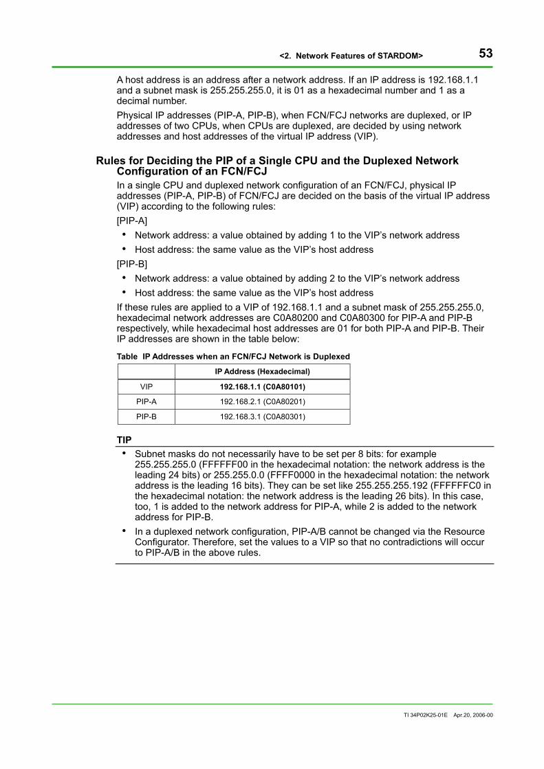
<2. Network Features of STARDOM> 53
TI 34P02K25-01E Apr.20, 2006-00
A host address is an address after a network address. If an IP address is 192.168.1.1 and a subnet mask is 255.255.255.0, it is 01 as a hexadecimal number and 1 as a decimal number. Physical IP addresses (PIP-A, PIP-B), when FCN/FCJ networks are duplexed, or IP addresses of two CPUs, when CPUs are duplexed, are decided by using network addresses and host addresses of the virtual IP address (VIP).
Rules for Deciding the PIP of a Single CPU and the Duplexed Network Configuration of an FCN/FCJ In a single CPU and duplexed network configuration of an FCN/FCJ, physical IP addresses (PIP-A, PIP-B) of FCN/FCJ are decided on the basis of the virtual IP address (VIP) according to the following rules: [PIP-A] • Network address: a value obtained by adding 1 to the VIP’s network address • Host address: the same value as the VIP’s host address
[PIP-B] • Network address: a value obtained by adding 2 to the VIP’s network address • Host address: the same value as the VIP’s host address
If these rules are applied to a VIP of 192.168.1.1 and a subnet mask of 255.255.255.0, hexadecimal network addresses are C0A80200 and C0A80300 for PIP-A and PIP-B respectively, while hexadecimal host addresses are 01 for both PIP-A and PIP-B. Their IP addresses are shown in the table below:
Table IP Addresses when an FCN/FCJ Network is Duplexed
IP Address (Hexadecimal)
VIP 192.168.1.1 (C0A80101)
PIP-A 192.168.2.1 (C0A80201)
PIP-B 192.168.3.1 (C0A80301)
TIP • Subnet masks do not necessarily have to be set per 8 bits: for example
255.255.255.0 (FFFFFF00 in the hexadecimal notation: the network address is the leading 24 bits) or 255.255.0.0 (FFFF0000 in the hexadecimal notation: the network address is the leading 16 bits). They can be set like 255.255.255.192 (FFFFFFC0 in the hexadecimal notation: the network address is the leading 26 bits). In this case, too, 1 is added to the network address for PIP-A, while 2 is added to the network address for PIP-B.
• In a duplexed network configuration, PIP-A/B cannot be changed via the Resource Configurator. Therefore, set the values to a VIP so that no contradictions will occur to PIP-A/B in the above rules.

<2. Network Features of STARDOM> 54
TI 34P02K25-01E Apr.20, 2006-00
Rules for Deciding the IP Address of a Duplexed CPU and a Single Network Configuration of an FCN In a duplexed CPU and single network configuration or a separated network configuration of an FCN, the IP address of the standby side CPU is decided on the basis of the IP address of the control side CPU according to the following rules: • Network address: the same value as the network address of the control side CPU • Host address: a value obtained by setting the most significant bit of the host
address of the control side CPU as 1 If these rules are applied to an IP address of 192.168.1.1 with a subnet mask of 255.255.255.0 for the control side CPU in a single network configuration, the network address remains C0A80100 and the host address is 81 (10000001 in the binary notation) in the hexadecimal notation with respect to the IP address of the standby side CPU. Thus, the IP address of the standby side CPU is C0A80181 = 192.168.1.129. IP addresses of control side/standby side CPUs are shown in the table below:
Table IP Addresses of Control Side/Standby Side CPUs
IP Address of Control Side CPU (Hexadecimal) IP Address of Standby Side CPU (Hexadecimal)
192.168.1.1 (C0A80101) 192.168.1.129 (C0A80181)
In this configuration, the IP addresses of two duplexed CPUs are alternated every time they switch from the control side to the standby side and vice versa.
TIP • In a single network configuration or in a separated configuration, there is no distinction between the
virtual IP address (VIP) and the physical IP address (PIP). IP addresses are simply treated as those of the control side/standby side.
• The IP address of the standby side CPU when CPUs are duplexed in the FCN is, as mentioned above, the value obtained by setting the most significant bit of the host address of the control side IP address as 1. For the IP address of the control side CPU, therefore, use a host address whose most significant bit is 0. For example, if a subnet mask is 255.255.255.0 and 1 to 126 (01 to 7E in the hexadecimal notation) is used for the host address of the control side CPU, the host address of the standby side CPU becomes 129 to 254 (81 to FE in the hexadecimal notation). Similarly, if a subnet mask is 255.255.255.192 and 1 to 62 (01 to 3E in the hexadecimal notation) is used for the host address of the control side CPU, the host address of the standby side CPU becomes 65 to 126 (41 to 7E in the hexadecimal notation).
• In a single network configuration or in a separated configuration, the standby side CPU’s IP address decided according to the above rules can be changed via the Resource Configurator.

<2. Network Features of STARDOM> 55
TI 34P02K25-01E Apr.20, 2006-00
Rules for Deciding the IP Address of a Duplexed CPU and a Duplexed Network Configuration of an FCN In a duplexed CPU and a duplexed network configuration of an FCN, the PIP-A/B of left/right CPUs are determined on the basis of the FCN’s VIP regardless of the control side/standby side according to the following rules: [PIP-A of the left CPU] • Network address: a value obtained by adding 1 to the VIP’s network address • Host address: the same value as the VIP’s host address
[PIP-B of the left CPU] • Network address: a value obtained by adding 2 to the VIP’s network address • Host address: the same value as the VIP’s host address
[PIP-A of the right CPU] • Network address: a value obtained by adding 1 to the VIP’s network address • Host address: a value obtained by setting the most significant bit of the VIP’s host
address as 1 [PIP-B of the right CPU] • Network address: a value obtained by adding 2 to the VIP’s network address • Host address: a value obtained by setting the most significant bit of the VIP’s host
address as 1 As described above, host addresses of the PIP-A/B of the right CPU are the values obtained by setting the most significant bit of the VIP’s host address as 1. If this is applied to a VIP of 192.168.1.1 with a subnet mask of 255.255.255.0 (the host address is 01 in the hexadecimal notation), the PIP-A/B host addresses of the right CPU become 81 in the hexadecimal notation (10000001 in the binary notation) or 129 in the decimal notation. If these rules are applied to a VIP of 192.168.1.1 with a subnet mask of 255.255.255.0, PIP/A and PIP-B are decided as in the table below:
Table IP Addresses of Righ/Left CPUs
IP Address of the Left CPU (Hexadecimal) IP Address of the Right CPU (Hexadecimal)
VIP 192.168.1.1 (C0A80101) < to be allocated to the control side CPU >
PIP-A 192.168.2.1 (C0A80201) 192.168.2.129 (C0A80281)
PIP-B 192.168.3.1 (C0A80301) 192.168.3.129 (C0A80381)
In this configuration, VIP allocations of two duplexed CPUs are changed every time CPUs switch from the control side to the standby side and vice versa. However, PIP-A and PIP-B are fixed for use without being changed.

<2. Network Features of STARDOM> 56
TI 34P02K25-01E Apr.20, 2006-00
TIP • The IP address of the right CPU when CPUs are duplexed in an FCN is, as mentioned above, the
value obtained by setting the most significant bit of the VIP’s host address as 1. For the VIP, therefore, use a host address whose most significant bit is 0. For example, if a subnet mask is 255.255.255.0 and 1 to 126 (01 to 7E in the hexadecimal notation) is used for a host address of VIP, a host address of the right CPU becomes 129 to 254 (81 to FE in the hexadecimal notation). Similarly, if a subnet mask is 255.255.255.192 and 1 to 62 (01 to 3E in the hexadecimal notation) is used for a host address of VIP, a host address of the right CPU becomes 65 to 126 (41 to 7E in the hexadecimal notation).
• In a duplexed network configuration, PIP-A/B cannot be changed via the Resource Configurator. Therefore, set the values to a VIP so that no contradictions will occur with PIP-A/B in the above-mentioned rules.
SEE ALSO For an example of IP address value, see "3.8 Duplexing Networks".

<2. Network Features of STARDOM> 57
TI 34P02K25-01E Apr.20, 2006-00
Various Topologies For duplexed control networks, various network topologies can be employed. The following subsections explain each topology briefly, and which to be employed through comparing each feature.
Single LAN
FCN/FCJ
PLC
HUB
A B
VDS Data Server
A
Dual Interface Device
HMI
Single Interface Device
FCN/FCJ
A B B A
Control -side
Standby -side
Figure Single LAN Configuration
In this configuration, the network path is not duplexed, which does not provide alternative path on the occasion of network failure.
Dual LAN
FCN/FCJ
PLC
HUB-A HUB-B
A B
VDS Data Server
A B
Dual Interface Device
HMI
Single Interface Device
FCN/FCJ
A B B A
Control -side
Standby -side
Figure Dual LAN Configuration
This is a network topology where network interfaces of nodes are duplexed and cables and hubs connecting them each other are duplexed, as well as physically independent. The highest fault tolerance is assured. Connect single interface devices to HUB-A. The network is not duplexed on a single interface device and used only with Network-A.

<2. Network Features of STARDOM> 58
TI 34P02K25-01E Apr.20, 2006-00
Guide for Selecting an Optimum Network Topology The following table lists features of network topologies, which may be helpful as a measure for selecting the optimum topology.
Table Comparing Network Topologies Single LAN Dual LAN
Reliability Low High (No common part ) Network load Low Low
Cost (Network devices) Low High Wiring Simple Relatively complicated
Choose the optimum network topology according to the features of your application (intended purpose, connecting devices, location, etc.). For a standard network configuration that consists of FCN/FCJ and VDS, it is recommended to employ dual LAN in the light of reliability and easy maintenance.
Internal Operations in the Duplexed Network Function This section explains the internal operations in the duplexed network function of STARDOM.
Network Status Table (NSTBL) Network functions of FCN/FCJ or VDS connected to a control network manage statuses of network interfaces (network statuses) of each node as a network interface status table (NSTBL). For nodes with the duplexed network function, information of standby side network interface is also managed. All VDSs and FCNs/FCJs have NSTBLs used for algorisms of network failure, switching between network paths, network recovery, etc. NSTBL contains the following information:
Table Example of Network Status Table Network Path Information Device
Index VIP PIP-A PIP-B Network-A Network-B
1 192.168.0.1 192.168.1.1 192.168.2.1 OK OK 2 192.168.0.2 192.168.1.2 192.168.2.2 OK OK 3 192.168.1.130 192.168.2.130 OK OK

<2. Network Features of STARDOM> 59
TI 34P02K25-01E Apr.20, 2006-00
Diagnostic Communication Frame Duplexed network function of FCN/FCJ or VDS connected to a control network performs periodically multicast transport of network interface statuses as diagnostic communication frames, for updating NSTBL. The diagnostic communication frames store NSTBL managed by the node. A node that received diagnostic communication frames of other node updates its NSTBL based on the information stored in that frame. Diagnostic communication frames are transmitted by each dual interface individually. The default diagnostic communication interval is 500ms. The two consecutive failures of diagnostic communications are recognized as a failure, making switching time 1000 to 1500 ms when diagnostic communication interval is 500ms. Diagnostic communication frames are sent in conjunction with the number of duplexed devices (such as FCNs or VDSs) to a network and are received by the devices. These devices process frames every time they are received: the greater the number of duplexed devices, the greater the reception processing of diagnostic communication frames, thereby increasing the load on CPUs. Therefore, if the number of duplexed devices is substantial, the transmission cycle of diagnostic communication frames should be extended. The table below provides a guide for the number of devices and diagnostic cycles.
Table Guide for the Number of CPUs and the Diagnostic Cycles
Number of CPUs Diagnostic Cycle (msec) Remarks
Up to 12 500 Default value for diagnostic cycles
13 to 25 1,000
26 to 37 1,500
38 to 50 2,000
51 to 62 2,500
63 to 75 3,000
76 to 87 3,500
88 to 100 4,000
101 to 112 4,500
113 to 125 5,000
126 to 137 5,500
138 to 150 6,000
151 to 162 6,500
163 to 175 7,000
176 to 187 7,500
188 to 200 8,000
201 to 212 8,500
213 to 225 9,000
226 to 237 9,500
238 to 248 10,000 Note: The number of CPUs is the total number of FCNs/FCJs/VDSs in a network which uses the network duplex function (if
CPUs of an FCN are duplexed, the number of CPUs is 2).

<2. Network Features of STARDOM> 60
TI 34P02K25-01E Apr.20, 2006-00
SEE ALSO For the communication load of diagnostic communication frames, see "2.3 Communication Performances".
Network Failure A network failure is the status where one of dual network paths is unavailable. The network failure is managed per node. If diagnostic communication frames cannot be received from a node, the network path to the node is recognized to be failed, which is notified to the operator as a message. The cause of failures can be as follows: failure of network interface of own node, failure of network interface of the destination node, failure of network devices (hubs and cables) on the network path between the two nodes, communication jamming due to the temporary noises, etc.
Switching between Network Paths If a network failure to a node is detected, Routing Table is automatically changed, switching immediately over another of dual network paths.
Network Recovery The node that detects a network failure continues to monitor the failed network. If the recovery is detected, the message notifying the network recovery is sent to the operator.

<2. Network Features of STARDOM> 61
TI 34P02K25-01E Apr.20, 2006-00
Supporting Duplexed CPU of FCN When a control side CPU (controlling the system) of FCN fails, the control right is moved to a standby side CPU (: this side always equalizes with the control side and in waiting status to receive the control right in the case that the control side fails). The equalization between the control side and standby side is performed via the control network. The CPU that newly acquires the control right continues to communicate, by succeeding the network information (virtual IP addresses, host names, etc.) of the CPU that previously had the control. Other nodes that had been communicated with FCN whose CPU was switched, detect the switching between network paths, switching over another path automatically. This function ensures seamless operations for applications of the nodes that had been communicated with the FCN.
Host Name and IP Address A host name and IP address (VIP) with duplexed CPU is consistent and can be recognized as a single device for applications of a client (e.g. VDS). When the switching takes place between CPUs in FCN, the VIP is also moved to the CPU that takes control immediately.
Standby Side CPU Network Interface Status The network interface statuses of the standby side CPU are always checked and the results are reflected to NSTBL.

<2. Network Features of STARDOM> 62
TI 34P02K25-01E Apr.20, 2006-00
2.7 Cautions for Network Configuration
Connecting other devices on to network The communication loads between FCN/FCJ and other devices such as PLC, field devices, PC may influence the control function shown in the following table.
Table Influences on FCN/FCJ Communication Protocol Protocol Method Effects on FCN/FCJ
Unicast Communications to one specific node
Multicast Communications to one specific group of nodes
Communications to any devices other than FCN/FCJ never adversely affect FCN/FCJ.
Broadcast Communications to all nodes in the network
As communication processing has high priority, all types of communication frames, including irrelevant ones, are received by the FCN/FCJ. When broadcast communication loads are too high, the control processing of the FCN/FCJ is influenced (for example, processing delay can occur).
The broadcast communications increase the communication loads, so that connecting FCN/FCJ to the network with broadcast communications should be avoided. If the connections are required, separate broadcast domain via router or VLAN shown in the following documentation.
SEE ALSO For the use of routers, refer to the following:
1. “Figure Example of a Single Network Configuration” and “Figure Example of a Separated Network Configuration” in “2.2 Network Basic Definitions (IP Address Settings)”
2. “3.6 Connecting Routers to Control Networks”
CAUTION
1. The broadcast communications are also used as ARP (Address Resolution Protocol). If a number of devices using ARP are connected to the network, the massive broadcast communications may occur.
2. Even if under not frequent broadcast communication environment, the massive broadcast communication might occur due to the abnormal condition of devices.
Therefore the switching HUBs with the broadband suppression function are recommended to be installed.

<3. Examples of Network Configurations> 63
TI 34P02K25-01E Apr.20, 2006-00
3. Examples of Network Configurations Devices and functions provided by STARDOM are highly independent, enabling to construct various systems in combination with other open devices. This chapter explains needed information for constructing a system and examples of network configuration.
3.1 Small Two-layered System (Standard)
FCJ
HUB
1 2
VDS Data Server
1
2
HUB
HMI2
HMI 1
Control System Information Network
Control Network
FCN
1 2
I/O I/O I/O I/O
Figure Example of Small Two-layered System

<3. Examples of Network Configurations> 64
TI 34P02K25-01E Apr.20, 2006-00
Connection Implement a network adapter on VDS, connect FCN/FCJ and HMI on the same control network. Use port 1 for network interface of FCN/FCJ.
Table Example of IP Address Setting in Small Two-layered System
Nodes Ports IP Addresses Settings Remarks
FCN 1 192.168.0.1 Resource Configurator Control network Single network setting
FCJ 1 192.168.0.2 Resource Configurator Control network Single network setting
1 172.16.1.1 Windows setting Control system information networkVDS data server
2 192.168.0.101 Windows setting Control network
HMI1 172.16.1.21 Windows setting Control system information network
HMI2 172.16.1.22 Windows setting Control system information network
SEE ALSO For the restrictions on connecting devices, see "2.1 Varieties of Basic Configurations".

<3. Examples of Network Configurations> 65
TI 34P02K25-01E Apr.20, 2006-00
3.2 Small One-layered System
FCJ
HUB
1 2
VDS Data Server
1 HMI 2
HMI 1
Control Network
FCN
1 2
I/O I/O I/O I/O
Figure Example of small One-layered System
Connection Implement a network adapter on VDS, connect FCN/FCJ and HMI on the same control network. Use port 1 for network interface of FCN/FCJ.
Table Example of IP Address Configuration in Small One-layered System
Nodes Ports IP Addresses Settings Remarks
FCN 1 192.168.0.1 Resource Configurator Single network setting
FCJ 1 192.168.0.2 Resource Configurator Single network setting
VDS data server 1 192.168.0.101 Windows setting
HMI1 192.168.0.121 Windows setting
HMI2 192.168.0.122 Windows setting
SEE ALSO For the restrictions on connecting devices, see "2.1 Varieties of Basic Configurations".

<3. Examples of Network Configurations> 66
TI 34P02K25-01E Apr.20, 2006-00
3.3 Medium Scale Two-layered System
FCJ 1
HUB
1 2
VDS
Data Server 1
1
2
HUB
HMI 2
HMI 1
Control System Information Network
Control Network
FCN 1
1 2
VDS
Data Server 2
1
2
FCJ 2
1 2
HUB
FCN 2
1 2
I/O I/O I/O I/O I/O I/O I/O I/O
Figure Example of Medium Scale Two-layered System

<3. Examples of Network Configurations> 67
TI 34P02K25-01E Apr.20, 2006-00
Connection Implement two network adapters per VDS, one for control network connecting FCN/FCJ, the other for control system information network connecting HMI or upper computers. One of VDSs is used as an HMI server. Use port 1 for network interface of FCN/FCJ.
Table Example of IP Address Setting in Medium Scale Two-layered System
Nodes Ports IP Addresses Settings Remarks
FCN1 1 192.168.0.1 Resource Configurator Control network Single network setting
FCJ1 1 192.168.0.2 Resource Configurator Control network Single network setting
1 172.16.1.1 Windows setting Control system information networkVDS data server1 2 192.168.0.101 Windows setting Control network
FCN2 1 192.168.20.1 Resource Configurator Control network Single network setting
FCJ2 1 192.168.21.2 Resource Configurator Control network Single network setting
1 172.16.1.2 Windows setting Control system information networkVDS data server2 2 192.168.20.101 Windows setting Control network
HMI1 172.16.1.21 Windows setting Control system information network
HMI2 172.16.1.22 Windows setting Control system information network
SEE ALSO For the restrictions on connecting devices, see "2.1 Varieties of Basic Configurations".

<3. Examples of Network Configurations> 68
TI 34P02K25-01E Apr.20, 2006-00
3.4 Installing Controllers in a Field as Standalone An autonomous controller FCN/FCJ can be installed on the devices of the field as a standalone controller. VDS is not needed for this type of configuration.
FCN/FCJ
Resource Configurator Web Browser
Ethernet Cross Cable
1 2Serial Port
Modem
WAN
I/O I/O
RS232C Cable
Figure Example of Standalone Installation
Configuration and Maintenance When you perform configurations, maintenances or checks of devices, connect a PC on which Resource Configurator and Web browser are implemented, to the interface1 of FCN/FCJ (see the figure above). Using Ethernet cross cable, the wiring without network devices (e.g. hubs) are obtained. However, you can use hubs and straight cables as usual.
Remote Connection Connecting a modem to a serial port of FCN/FCJ enables connections to a WAN. You can create an application for accessing and monitoring information acquired by FCN/FCJ once a day.
SEE ALSO For remote connections, see "3.13 Monitoring and Maintaining FCN/FCJ Remotely".

<3. Examples of Network Configurations> 69
TI 34P02K25-01E Apr.20, 2006-00
When Duplexing CPU When CPU is duplexed on FCN, the equalization from the control side to the standby side is performed via the control network. Therefore, even when the FCN is installed as a standalone controller, it is necessary to connect the control side and the standby side over the network in the case that the CPU is duplexed. Use a cross cable to connect network interface2 or use a straight cable and a hub to connect network interface1.
Control -side
Resource Configurator Web Browser
Ethernet Cross Cable
1 2 1 2
Standby -side
EthernetCross Cable
Resource Configurator Web Browser
Ethernet Straight Cable HUB
FCN
Control -side
1 2 1 2
Standby -side
FCN
Figure Standalone Installation with duplexed CPU

<3. Examples of Network Configurations> 70
TI 34P02K25-01E Apr.20, 2006-00
3.5 Connecting Simple HMI to Standalone Controller in a Field This section explains the configuration for monitoring control operations by connecting simple HMI with FCN/FCJ installed in the field.
Using VDS as HMI
FCN/FCJ
HMI (Web browser) Data/HMI Server
Resource Configurator
Ethernet Cross Cable
1 2
Hub Connecting to Upper Device
Ethernet Straight Cable
I/O I/O
Figure Connecting VDS as HMI to an FCN/FCJ
As HMI, use a PC on which VDS Data/HMI Server functions, Web browsers, Resource Configurator and Logic Designer are installed. For wiring, use Ethernet cross cables to connect to the network interface1 of FCN/FCJ. There is no problem if you use hubs and straight cables. If you connect the network to upper devices, connect from HMI to upper computers. Configure router functions to HMI if you want to communicate from the upper devices to FCN/FCJ directly.
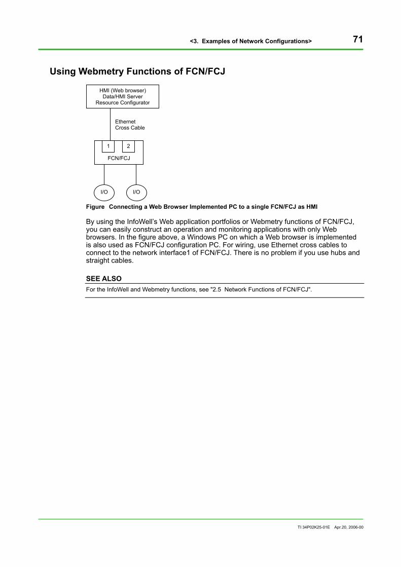
<3. Examples of Network Configurations> 71
TI 34P02K25-01E Apr.20, 2006-00
Using Webmetry Functions of FCN/FCJ
FCN/FCJ
HMI (Web browser) Data/HMI Server
Resource Configurator
Ethernet Cross Cable
1 2
I/O I/O
Figure Connecting a Web Browser Implemented PC to a single FCN/FCJ as HMI
By using the InfoWell’s Web application portfolios or Webmetry functions of FCN/FCJ, you can easily construct an operation and monitoring applications with only Web browsers. In the figure above, a Windows PC on which a Web browser is implemented is also used as FCN/FCJ configuration PC. For wiring, use Ethernet cross cables to connect to the network interface1 of FCN/FCJ. There is no problem if you use hubs and straight cables.
SEE ALSO For the InfoWell and Webmetry functions, see "2.5 Network Functions of FCN/FCJ".

<3. Examples of Network Configurations> 72
TI 34P02K25-01E Apr.20, 2006-00
Connecting Programmable Displays to Serial Port
FCN/FCJ
Web Browser Resource Configurator
Ethernet Cross Cable
1 2Serial Port
Programmable Displays
RS232CCable
I/O I/O
Figure Connecting Programmable Displays to FCN/FCJ
Using FA-M3 emulation features of FCN/FCJ, you can connect GP series programmable displays of Digital Electronics Co. via RS-232C port. For wiring to programmable displays, use serial communication cables connecting to COM port of FCN/FCJ. For configurations of FCN/FCJ, connect a PC on which Web browsers and Resource Configurator are installed, to the network interface1 of FCN/FCJ via Ethernet cross cables. There is no problem if you use hubs and straight cables.

<3. Examples of Network Configurations> 73
TI 34P02K25-01E Apr.20, 2006-00
3.6 Connecting Routers to Control Networks To connect control network devices directly to upper devices like the ones on control system information network, you need to install routers between the networks for routing of communication frames. There are two ways for routing: routing communication frames using a PC on which VDS data server is mounted, and installing exclusive router devices.
FCJ
Router
HUB
1 2
VDS Data Server
1HMI
2
HUB
HMI HMI
HMI Control System Information Network
Control Network
HUB
FCN
1 2
Figure Connecting Routers to Control Network
Security The control network is highly secure network requiring real-time operations and reliability; you need to be careful when you perform routing functions between the control network and other networks. Take count of securities or loads of control networks, introducing filtering of unneeded accesses or firewalls.

<3. Examples of Network Configurations> 74
TI 34P02K25-01E Apr.20, 2006-00
Configuration of Routing Information You need to perform default gateway settings to the devices connected to control networks that communicate to upper networks.
SEE ALSO For the configuration of default gateway, see "2.2 Network Basic Definitions (IP Address Settings)".
You need to add routing information besides default gateway settings when connecting two or more routers to a control network as in the example of this chapter and configuring routers to switch according to the target device.
How to Configure FCN/FCJ 1. Click the link of [Edit] in "System File Setting" from the maintenance menu. Select
"IP Routing File" on the system configuration file window and click [OK]. 2. On the IP routing file edit window, add the routing information in the following
format. net <destination> gateway <gateway>
host <destination> gateway <gateway>
"net" is the keyword that indicates the <destination> is a network; "host" is the keyword that indicates the <destination> is a host. Specify names or IP addresses for <destination> and <gateway>.
e.g. net 192.168.3.0 gateway vds01
net 192.168.9.0 gateway 192.168.0.252
host hmi10 gateway 192.168.0.252
How to Configure VDS Add routing information using the ROUTE command on the DOS command window. e.g.
ROUTE -P ADD 192.168.99.0 MASK 255.255.255.0.192.168.6.10

<3. Examples of Network Configurations> 75
TI 34P02K25-01E Apr.20, 2006-00
3.7 Connecting Several Control Networks to VDS When connecting devices other than FCN/FCJ (e.g. PLC), you may well connect to another network, separating physically from the network connecting to FCN/FCJ. Thereby communications with devices other than FCN/FCJ using exclusive protocols (e.g. MELSEC-NET, FL-NET) can be guarded from external perturbations arise from the communications to FCN/FCJ.
FCJ
HUB
1 2
VDS Data Server
3
1
HUB
HMI 1
HMI2
Control System Information Network
Control Network1
FCN
1 2
HUB
2PLC2
PLC 1
Control Network2
Figure Connecting Several Control Network to VDS
In the example above, three network adapters are installed on a VDS; connecting network interface1 to control network1; interface2 to control network2; interface3 to control network3.
Table Example of IP Address Setting when Connecting Several Control Networks to VDS
Nodes Ports IP Addresses Settings Remarks
FCN 1 192.168.0.1 Resource Configurator Control network1 Single network setting
FCJ 1 192.168.0.2 Resource Configurator Control network1 Single network setting
1 172.16.1.1 Windows setting Control system information network
2 192.168.0.101 Windows setting Control network1 VDS data server
3 192.168.20.101 Windows setting Control network2
PLC1 192.168.20.1 Setting Defined by the PLC Control network2
PLC2 192.168.20.2 Setting Defined by the PLC Control network2
HMI1 172.16.1.21 Windows setting Control system information network
HMI2 172.16.1.22 Windows setting Control system information network

<3. Examples of Network Configurations> 76
TI 34P02K25-01E Apr.20, 2006-00
3.8 Duplexing Networks For control networks, it is possible to duplex network interfaces, cables and hubs using the duplexed network function of STARDOM. This section explains a typical example of duplexed network system attained through the duplexed network function of STARDOM.
FCJ
HUB-A
HUB-A
PLC
HUB-B
FCN
Configu-ration
PC
HMIClient
HUB-A
VDS
HUB-B HUB-B
FCJ Control-side
Standby -side
1
2
1
2 2
1
2 2
1
2
FCN 1 1
Figure Example of Duplexed Network Configuration
Installation of Devices and Wirings Install hubs for Networks-A and Networks-B separately. Connect a single interface device to HUBs-A.
SEE ALSO For the features of network topologies, see "2.6 Duplexing Control Network".
Connecting FCN/FCJ Connect interface1 to HUB-A, interface2 to HUB-B. For the FCN with a duplexed CPU, install wirings for both control side CPU and standby side CPU.

<3. Examples of Network Configurations> 77
TI 34P02K25-01E Apr.20, 2006-00
IP Address Setting to FCN/FCJ Configure VIP to IP addresses using Resource Configurator.
SEE ALSO For IP address settings to FCN/FCJ, see "2.2 Network Basic Definitions (IP Address Settings)".
For your reference, the examples of IP addresses configured to each network interface of the FCN with duplexed CPU are indicated as follows: [Control side] Interface A: IP address = 192.168.0.1, Subnet mask = 255.255.255.0 (VIP) IP address = 192.168.1.1, Subnet mask = 255.255.255.0 (PIP-A) Interface B: IP address = 192.168.2.1, Subnet mask = 255.255.255.0 (PIP-B) [Standby side] Interface A: IP address = 192.168.1.129, Subnet mask = 255.255.255.0 (PIP-A) Interface B: IP address = 192.168.2.129, Subnet mask = 255.255.255.0 (PIP-B)
Parameter Settings of FCN/FCJ Set the “Network” of “CPU Module” – “General” of the Resource Configurator to “Duplex.”

<3. Examples of Network Configurations> 78
TI 34P02K25-01E Apr.20, 2006-00
Connecting VDS Install two network interface cards, each of which connects to HUB-A and HUB-B.
IP Address Configuration to VDS Configure VIP, PIP-A and PIP-B on Windows 2000/XP network configurations. Configure VIP and PIP-A to the network interface card connecting to HUB-A; configure PIP-B to the network interface card connecting to HUB-B.
SEE ALSO For IP address settings to VDS, see "D2.3 IP Address Setting Procedure to VDS" in "FCN/FCJ Guide" (IM 34P02Q01-01E).
Parameter Settings of VDS Configure VIP using "FCN/FCJ Connection Setting Tool" of VDS. Start the tool and type VIP to "Virtual IP Address" in the "General" tab.
Connection and Configuration of Single Interface Device Be sure to connect a single interface device to HUB-A. If Network-A fails, the communication also fails because the communications are performed via Networks-A. Configure VIP for an IP address. For the sequence of configuration, see the manual of each device.

<3. Examples of Network Configurations> 79
TI 34P02K25-01E Apr.20, 2006-00
3.9 Connecting Devices (e.g.PLCs) Other than FCN/FCJ to VDS You can connect devices (e.g.PLCs) other than FCN/FCJ to VDS data server.
Basic (Single) Configuration You can connect devices other than FCN/FCJ including PLCs on the same network to which FCN/FCJ is connected. The following example shows a typical configuration and IP address settings.
FCJ
PLC
HUB
1 2
VDS Data Server
1HMI
FCN
1 2 2 1
Control -side
Standby -side
2
HUB
HMI
HMIHMI
Control System Information Network
Control Network
Figure Connecting Devices Other than FCN/FCJ to Control Network
Use port 1 as network interface of FCN/FCJ.
Table Example of IP Address Setting when Connecting VDS and PLC (Single Configuration)
Nodes Ports IP Addresses Settings Remarks
FCN 1 192.168.0.1 Resource Configurator Single network setting
FCJ 1 192.168.0.2 Resource Configurator Single network setting
PLC 192.168.0.3 Setting Defined by the PLC
VDS data server 1 192.168.0.101 Windows setting Control system information network (port2) requires individual setting
HMI 192.168.0.121 Windows setting
SEE ALSO For the restrictions on the number of connecting devices, see "2.1 Varieties of Basic Configurations".

<3. Examples of Network Configurations> 80
TI 34P02K25-01E Apr.20, 2006-00
When Control Network is Duplexed You can connect devices other than FCN/FCJ to a duplexed control network connecting FCN/FCJ. The following figure shows a typical example of configuration and IP address settings.
FCJ
PLC
HUB-B
1 2
VDS Data Server
1HMI
FCN
1 2 2 1
Control -side
Standby -side
3
HUB
HMI HMIHMI
Control System Information Network
Control Network
HUB-A
2
Figure Connecting Devices Other than FCN/FCJ to Duplexed Control Network
Connect PLCs to Network-A of the control network.
Table Example of IP Address Setting When Connecting VDS and PLC (Duplexed Configuration)
Nodes Ports IP Addresses Settings Remarks
FCN 1/2 192.168.0.1 Resource Configurator Configure only VIP. PIP is automatically set. Duplexed network setting
FCJ 1/2 192.168.0.2 Resource Configurator Configure only VIP. PIP is automatically set. Duplexed network setting
PLC 192.168.0.3 Setting Defined by the PLC
Configure the same network address as VIP set to FCN/FCJ or VDS.
1 192.168.0.101(VIP) 192.168.1.101(PIP-A) Windows setting
VDS data server 2 192.168.2.101(PIP-B) Windows setting
Configure VIP and PIP-A to network interface1; PIP-B to network interface2. Control system information network side (port3) requires exclusive IP address.
HMI 192.168.0.121 Windows setting Configure the same network address as VIP set to FCN/FCJ or VDS.

<3. Examples of Network Configurations> 81
TI 34P02K25-01E Apr.20, 2006-00
3.10 Connecting PLC to FCN/FCJ FCN/FCJ can communicate to devices like PLCs, other than FCN/FCJ or VDS, via control networks. However, the network must be configured to avoid having influences on FCN/FCJ control by communication load lead from other devices.
SEE ALSO Refer to “2.7 Cautions for Network Configuration” when connecting devices other than VDS and FCN/FCJ devices to the network.
Basic (Single) Configuration You can connect devices (e.g.PLCs) other than FCN/FCJ to the same control network to which FCN/FCJ is connected. The following figure shows a typical example of configuration and IP address settings.
FCJ
PLC 1 2
VDS Data Server
1HMI
FCN
1 2 2 1
Control -side
Standby -side
3
HUB
HMI HMIHMI
Control System Information Network
Control Network
HUB
2
Figure Connecting PLC to FCN/FCJ
Use port1 for the network interface of FCN/FCJ. Use function block for PLC connections as control application of FCN/FCJ.
Table Example of IP Address when Connecting FCN/FCJ to PLC (Single Configuration)
Nodes Ports IP Addresses Settings Remarks
FCN 1 192.168.0.1 Resource Configurator Single network setting
FCJ 1 192.168.0.2 Resource Configurator Single network setting
PLC 192.168.0.3 Setting Defined by the PLC
VDS data server 1 192.168.0.101 Windows setting Control system information network side (port2) requires exclusive IP address
HMI 192.168.0.121 Windows setting

<3. Examples of Network Configurations> 82
TI 34P02K25-01E Apr.20, 2006-00
SEE ALSO For the restrictions on the number of connecting devices, see "2.1 Varieties of Basic Configurations".

<3. Examples of Network Configurations> 83
TI 34P02K25-01E Apr.20, 2006-00
When Control Network is Duplexed The following example explains the configuration when connecting devices other than FCN/FCJ to a duplexed control network connecting to FCN/FCJ.
FCJ
PLC
HUB-B
1 2
VDS Data Server
1HMI
FCN
1 2 2 1
Control -side
Standby -side
3
HUB
HMI HMIHMI
Control System Information Network
Control Network
HUB-A
2
Figure Example of Connecting PLC to FCN/FCJ on duplexed Network
Connect PLCs to Network-A of a control network. Use function block for PLC connections as the control application of FCN/FCJ.
Table Example of IP Address Setting When Connecting FCN/FCJ and PLC (Duplexed Configuration)
Nodes Ports IP Addresses Settings Remarks
FCN 1/2 192.168.0.1 Resource Configurator Configure only VIP. PIP is automatically set. Duplexed network setting
FCJ 1/2 192.168.0.2 Resource Configurator Configure only VIP. PIP is automatically set. Duplexed network setting
PLC 192.168.0.3 Setting Defined by the PLC
Configure the same network address as VIP set to FCN/FCJ or VDS.
1 192.168.0.101(VIP) 192.168.1.101(PIP-A) Windows setting
VDS data server 2 192.168.2.101(PIP-B) Windows setting
Configure VIP and PIP-A to network interface1; PIP-B to network interface2. Control system information network side (port3) requires exclusive IP address.
HMI 192.168.0.121 Windows setting Configure the same network address as VIP set to FCN/FCJ or VDS.
SEE ALSO For the restrictions on the number of connecting devices, see "2.1 Varieties of Basic Configurations".

<3. Examples of Network Configurations> 84
TI 34P02K25-01E Apr.20, 2006-00
Separated Network Configuration The figure below shows a configuration example in which network port 1 of the FCN/FCJ is connected to a control network (for communications with the VDS), while network port 2 is connected to a PLC-dedicated network (for communications with the PLCs).
VDS HMI
VDS HMI
VDS Data Server
FCN FCJ
PLC1 PLC2
Control Network
Control System Information Network
PLC-dedicated Network
2
1
1
2
1
Figure Example of a Separated Network with PLCs Connected to the FCN/FCJ
Table Examples of IP Addresses for Connection between the FCN/FCJ and the PLCs (Separated Network Configuration)
Nodes Ports IP Addresses Settings Remarks
FCN 1 192.168.0.1 Resource Configurator Single network setting
1 192.168.0.2 Resource Configurator Separated network setting (port 1 address) FCJ
2 192.168.20.3 Resource Configurator Separated network setting (port 2 address)
PLC1 192.168.20.1 Setting Defined by the PLC
PLC2 192.168.20.2 Setting Defined by the PLC
Specify the same network address as the address of FCJ’s port 2.
1 192.168.0.101 Windows setting For control networks VDS data server
2 172.16.1.1 Windows setting For control system information networks
HMI 172.16.1.21 Windows setting Specify the same network address as the control system information network side (port 2) of the VDS.
SEE ALSO For restrictions on the number of connecting devices, see "2.1 Varieties of Basic Configurations".

<3. Examples of Network Configurations> 85
TI 34P02K25-01E Apr.20, 2006-00
3.11 Operation with Remote HMI STARDOM realizes Web-based configuration of HMIs, allowing you to easily construct a system for operation and monitoring remotely via WAN including telephone lines and internet.
Example of Construction The following figure shows an example of system configuration using a WAN.
FCN FCN FCJ
VDS Data Server HMI Server
PLC
Control Network
HMI HMI
Control System Information Network
HMI
VDS Data
Server
Firewall VPN
Router
Information Network
... ...
Firewall VPN
Router
Remote Operation
WAN
Figure Example of Remote Operation
• As a WAN, you can use ISDN, leased line, frame relay or inexpensive internet. If you perform operation and monitoring remotely, choose an optimum WAN after due consideration of traffic at operation and monitoring, available network infrastructure, etc. To realize a full-scale operation, it is recommended to employ high-speed infrastructure, assured bandwidth, depending on the scale of operation.
• For connection part of a WAN, routers supporting protocols for connecting telephone lines, ISDN, leased lines, etc. are needed. If necessary, consider the installation of a firewall, VPN (Virtual Private Network) to acquire the needed security and band. Firewalls protect against external unauthorized accesses and tampering. VPN protects against wiretapping activities and passing off. For the network securities, follow the network policy of your company.
• For communication band of the part of WAN, calculate the actual traffic and employ the infrastructure with excess capacities. Consider the traffic when starting HMIs or time when events are concentrated as well as steady communication load when collecting data.
SEE ALSO For the estimation of traffic, see "2.3 Communication Performances".
• For infrastructures of WAN, use services provided by manufacturers of
communication infrastructure of each area (e.g. in Japan, NTT). WAN may be suspended due to accidents or engineering works. You can set backup WAN or duplex routers as necessary. See manuals of the router in use for the detailed procedures.

<3. Examples of Network Configurations> 86
TI 34P02K25-01E Apr.20, 2006-00
Internet Connection If failures occur in the system at a site, you can send internet mails to remote terminals from FCN/FCJ or VDS in the field or send mails to a cell phone via telephone lines. With that it is possible to notify the contact person who is not in the site of important events immediately. The same person can also simply send Internet mails to ask conditions of the site. By these functions, a contact person who has received an urgency mail calls Web browsers using a cell phone or a hand-held device to check conditions of the site. You can acquire the application that enables these functions.

<3. Examples of Network Configurations> 87
TI 34P02K25-01E Apr.20, 2006-00
3.12 Send Mails to/Receive Mails from VDS and FCN/FCJ If failures occur in the system at a site, you can send Internet mails to remote terminals from FCN/FCJ or VDS in the field or send mails to a cell phone via telephone lines. With that it is possible to notify the contact person who is not in the site of important events immediately. The same person can also simply send Internet mails to ask conditions of the site. By these functions, a contact person who has received an urgency mail calls Web browsers using a cell phone or a hand-held device to check conditions of the site. You can acquire the application that enables these functions.
Example of Construction The following figure indicates an example of system configuration to realize the following functions: inquire remote FCN/FCJ or VDS using internet mail functions and send urgent mails from remote FCN/FCJ to VDS.
FCN FCN FCJ
VDS HMI Server Data Server
PLC
Control Network
Cell Phones,
etc.
Control System Information Network
VDSHMI
Server
Dial-up Router
... ...
WAN
POP Server SMTP Server HMI
Figure Example of System Configuration with Mail Functions
• Connection between the devices of the field and WAN is performed using commercially available routers with dial-up, ISDN and ADSL connection functions. In the example above, a dial-up router for analog lines is used. See manuals of each router for the setting procedures.
• To connect to a WAN, take due account of securities. • For send and receive mails, a server dedicated to send/receive mails is required. In
the example above, POP server and SMTP server are installed in a company. If you cannot install a server for sending and receiving mails, you may use a server provided by providers or manufacturer of cell phones instead, according to your condition.
• Between a dial-up router and a VDS or FCN/FCJ, install firewalls or VPN routers as necessary.

<3. Examples of Network Configurations> 88
TI 34P02K25-01E Apr.20, 2006-00
Configurations of FCN/FCJ Mail Functions FCN/FCJ supports SMTP as send mail protocol; POP3 as receive mail protocol. Send/receive mail functions of FCN/FCJ can be defined in the maintenance windows on a Web browser. The following table lists setting items. For details of each, see other instruction manuals or online help files.
Table Configurations List of Mail Setting File
Functions Setting items Keys Default values
POP3 user name PopUser None
Communication trace output TraceMode NO Send/receive mails
Send/receive log output MailLog YES
POP3 password PopPassward None
POP3 server address PopServer None
Receive mail cycle RecvCycle 0 (m)
Maximum mail size MaxMailSize 2 (Kbyte)
Authorization phase AuthPhase None
Receive mails
Authorization error handling OnAuthError Send
SMTP server address SmtpServer None
Domain name Domain None
Mail sender TrueName None
Error mail send destination ErrorsTo None
Reply mail destination ReplyTo None
Send mail cycle SendCycle 0 (m)
Send mail spool size QueueSize 0 (Kbytes)
Send mail spool type QueueType Memory
Send mails
Maximum send error QueueExpire 5 (times)
Configuration Procedures 1. Click the link of [Edit] in "System Setting File" of the maintenance menu. Select "E-
Mail Configuration File" on the system setting file window and click [OK]. 2. On the mail function setting window, perform the needed configuration. For the
detailed explanation, see the online help files.
TIP When using the E-mail Application Portfolio of the InfoWell, the above configuration can be set in the portfolio’s setting window. Therefore, there is no need to be aware of the above E-mail Configuration File when using the portfolio.

<3. Examples of Network Configurations> 89
TI 34P02K25-01E Apr.20, 2006-00
3.13 Monitoring and Maintaining FCN/FCJ Remotely FCN/FCJ is an autonomous network controller, enabling easily to realize systems for operation and monitoring or maintaining remotely via a WAN. The following figure shows an example of system configuration for simple operation and monitoring and maintenances of FCN/FCJ remotely installed, via a WAN including telephone lines or internet.
FCN FCN FCJ
VDS Data Server HMI Server
PLC
Control Network
Web Browser
Control System Inforamtion Network
HMI
VDS Data
Server
Firewall VPN
Router
... ...
Firewall VPN
Router
Remote Operation
WAN
Figure Example of Monitoring Operation from Remote FCN/FCJ
Routing You need to install firewalls, authorization, and enciphere for securities of connections to a WAN. In the figure above, routers supporting firewalls and VPN are employed. The routing operations between a control network and a control system network are performed on VDS data server in the example above; however, another router can be installed.
SEE ALSO For the installation of routers, see "3.6 Connecting Routers to Control Networks".

<3. Examples of Network Configurations> 90
TI 34P02K25-01E Apr.20, 2006-00
Maintenances of FCN/FCJ By specifying URL of an FCN/FCJ on a Web browser, the maintenance homepage of the FCN/FCJ is displayed. Using this function, you can check or change configurations of FCN/FCJ remotely.
Operation and Monitoring on Web Browser Using the Web Application Portfolio or Webmetry functions, you can construct simple operation and monitoring windows.
CAUTION
Communication protocols for some Web windows of the Web Application Portfolio and windows of the Webmetry functions do not generally pass through firewalls. If these windows need to be displayed via a firewall, set passage to be allowed through the firewall’s port 34170.
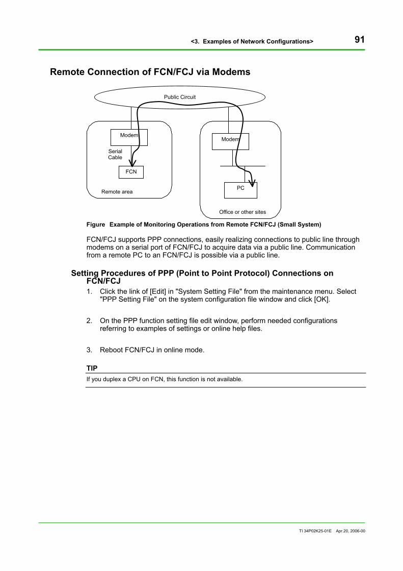
<3. Examples of Network Configurations> 91
TI 34P02K25-01E Apr.20, 2006-00
Remote Connection of FCN/FCJ via Modems
FCN
PC
Modem
Office or other sites
Public Circuit
Modem
Remote area
SerialCable
Figure Example of Monitoring Operations from Remote FCN/FCJ (Small System)
FCN/FCJ supports PPP connections, easily realizing connections to public line through modems on a serial port of FCN/FCJ to acquire data via a public line. Communication from a remote PC to an FCN/FCJ is possible via a public line.
Setting Procedures of PPP (Point to Point Protocol) Connections on FCN/FCJ 1. Click the link of [Edit] in "System Setting File" from the maintenance menu. Select
"PPP Setting File" on the system configuration file window and click [OK]. 2. On the PPP function setting file edit window, perform needed configurations
referring to examples of settings or online help files. 3. Reboot FCN/FCJ in online mode.
TIP If you duplex a CPU on FCN, this function is not available.

<3. Examples of Network Configurations> 92
TI 34P02K25-01E Apr.20, 2006-00
3.14 Setting FCN/FCJ and VDS Remotely If you install FCN/FCJ remotely from VDS data server, or in a separated building, the configuration can be as follows:
FCN FCN
VDS Data
Server
Control Network
HMIVDS HMI Server
...
Switching HUB
Optical Fiber Optical Fiber
Area1
Area2 Area3
Switching HUB
Switching HUB
FCN FCN
...
Figure Example of Control Network in Remote Areas
Wiring If you connect devices in separate buildings or remote places, use optical fiber that enables long-distance transmissions and is fairly resistant to noise. However, the total distance of CAT5 twisted pair cable is 100 m at most because it is exclusive of indoor wiring; it is not appropriate for wiring between separated buildings or in long distances. To use optical fibers, prepare a switching hub with an optical fiber interface of at least 100 Mbps.
Setting Parameters There are no parameters to be set.
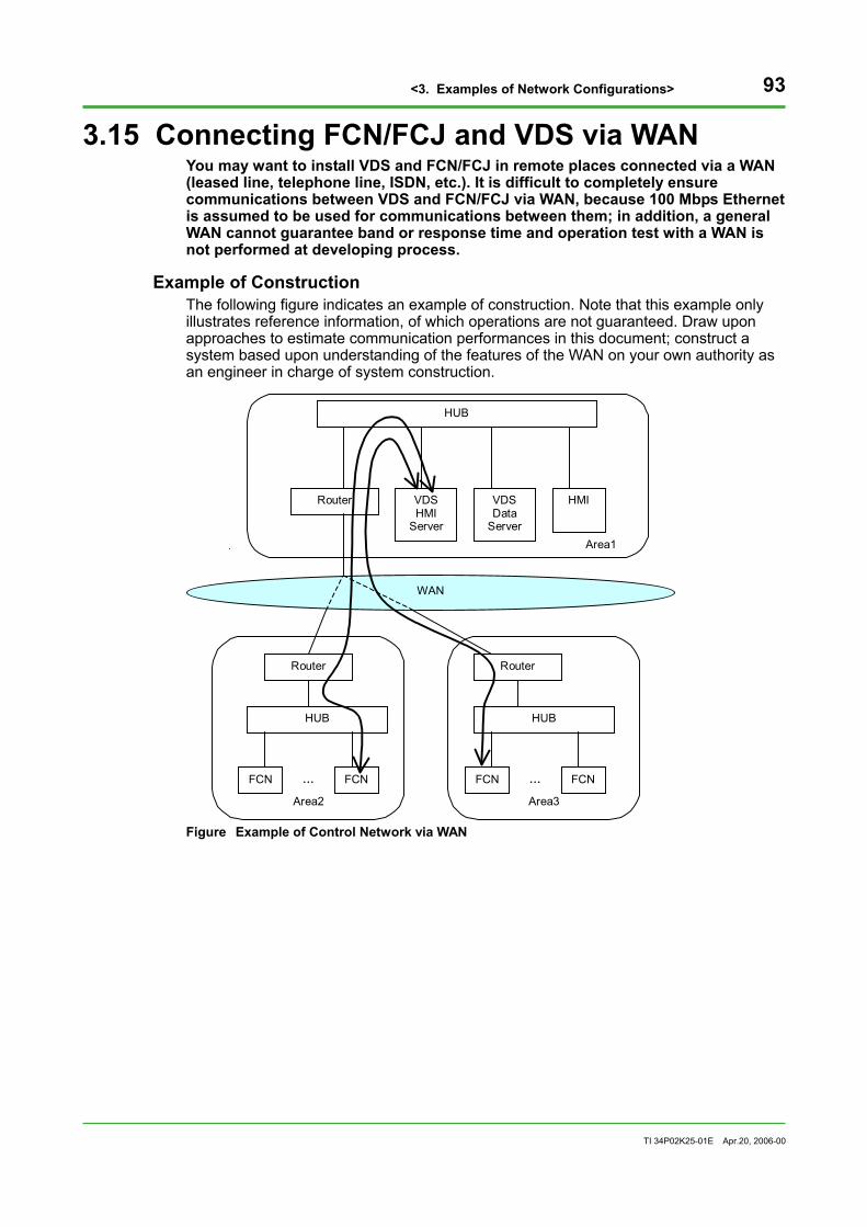
<3. Examples of Network Configurations> 93
TI 34P02K25-01E Apr.20, 2006-00
3.15 Connecting FCN/FCJ and VDS via WAN You may want to install VDS and FCN/FCJ in remote places connected via a WAN (leased line, telephone line, ISDN, etc.). It is difficult to completely ensure communications between VDS and FCN/FCJ via WAN, because 100 Mbps Ethernet is assumed to be used for communications between them; in addition, a general WAN cannot guarantee band or response time and operation test with a WAN is not performed at developing process.
Example of Construction The following figure indicates an example of construction. Note that this example only illustrates reference information, of which operations are not guaranteed. Draw upon approaches to estimate communication performances in this document; construct a system based upon understanding of the features of the WAN on your own authority as an engineer in charge of system construction.
Area1
Area3
Area2
FCN FCN
VDSData
Server
HMIVDS HMI
Server
...
Router
Router
Router
WAN
HUB
HUB
FCN FCN...
HUB
Figure Example of Control Network via WAN

<3. Examples of Network Configurations> 94
TI 34P02K25-01E Apr.20, 2006-00
Notes for Communication Performances In the example above, VDS data server acquires data of remote FCN/FCJ. Between a WAN and the connecting part, routers according to the infrastructure are installed. The communications between VDS data server and FCN/FCJ include steady data acquisitions as well as uploading of definition data at starting-up, and concentrations of events. Therefore, you should employ the infrastructure with excess band for the WAN to correspond to the traffic during starting-up and event concentration, in addition to the steady state.
SEE ALSO For the estimation of communication performances, see "2.3 Communication Performances".
Configurations Be sure to configure the default gateway of remote FCN/FCJ and VDS correctly.
SEE ALSO For the settings of default gateway, see "2.2 Network Basic Definitions (IP Address Settings).

<3. Examples of Network Configurations> 95
TI 34P02K25-01E Apr.20, 2006-00
3.16 Connecting Remote Devices to Duplexed Control Network This section explains the network configuration when connecting remote devices to duplexed control networks.
Example of Construction STARDOM duplexed network function is not available for communications to remote devices. Therefore, the connection to a WAN is performed only in HUB-A as shown in the figure below.
HUB-A
HUB-A
HUB-B
FCJ
HUB-B
VDS
HUB-A
WAN
Router
Router
Router
Router
2
1
2
1
FCN 2
1 FCJ
2
1
Control-side
Standby -side 2 2
FCN 1 1
Figure Example of Connecting Control Network to WAN
Connection A router connecting to a WAN is connected to HUB-A as a single interface device. When performing routing, you need to configure the related devices. For the configuration of the router, see the instruction manual of each router.

<3. Examples of Network Configurations> 96
TI 34P02K25-01E Apr.20, 2006-00
Duplexing WAN Part The part of router and WAN can be duplexed using a duplexed network function of the router. As shown in doted lines in the figure above, connect backup routers to HUBs-A and to the WAN for the backup side. The WAN on the primary side and on the backup side should be physically different. With that configuration, if the WAN (or the router supporting WAN) fails, the path is switched automatically over another one. For a duplexed network function of a router, see the manual of each router.
TIP Because the communication band on a WAN is not completely guaranteed, the STARDOM duplexed control network function does not apply to the part of the WAN network.
Configurations Be sure to configure the default gateway of the remote FCN/FCJ and VDS correctly.
SEE ALSO For the settings of default gateway, see "2.2 Network Basic Definitions (IP Address Settings)".
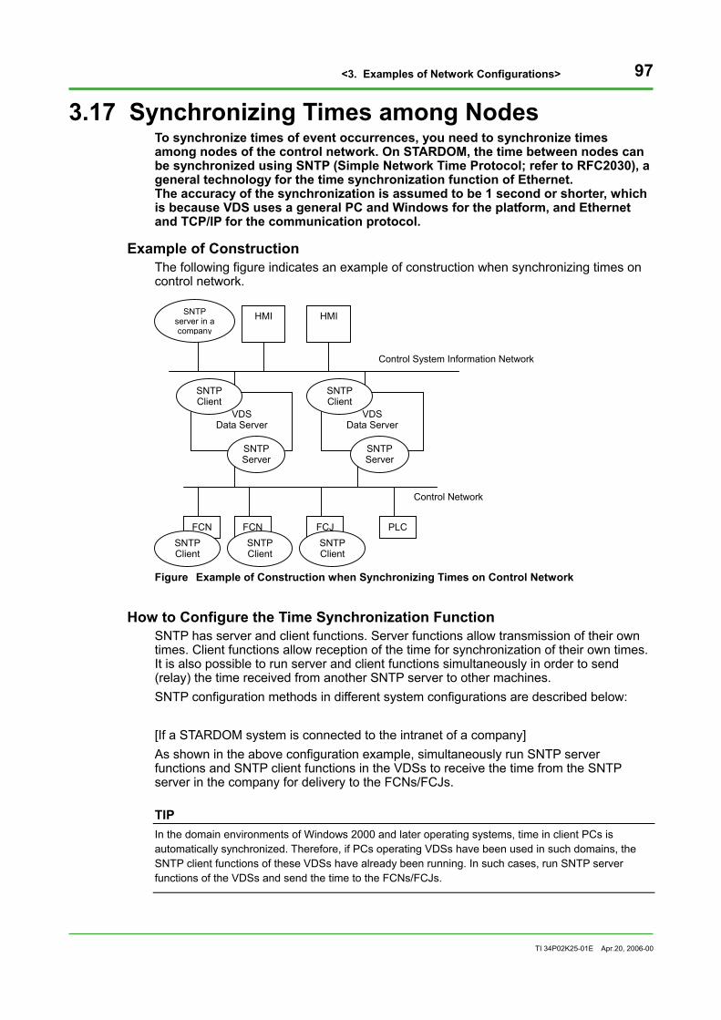
<3. Examples of Network Configurations> 97
TI 34P02K25-01E Apr.20, 2006-00
3.17 Synchronizing Times among Nodes To synchronize times of event occurrences, you need to synchronize times among nodes of the control network. On STARDOM, the time between nodes can be synchronized using SNTP (Simple Network Time Protocol; refer to RFC2030), a general technology for the time synchronization function of Ethernet. The accuracy of the synchronization is assumed to be 1 second or shorter, which is because VDS uses a general PC and Windows for the platform, and Ethernet and TCP/IP for the communication protocol.
Example of Construction The following figure indicates an example of construction when synchronizing times on control network.
VDS
Data Server
FCN FCN FCJ
VDS
Data Server
PLC
Control Network
HMI HMI
Control System Information Network
SNTP Server
SNTP Client
SNTP Client
SNTP Client
SNTP server in a company
SNTP Client
SNTP Server
SNTP Client
Figure Example of Construction when Synchronizing Times on Control Network
How to Configure the Time Synchronization Function SNTP has server and client functions. Server functions allow transmission of their own times. Client functions allow reception of the time for synchronization of their own times. It is also possible to run server and client functions simultaneously in order to send (relay) the time received from another SNTP server to other machines. SNTP configuration methods in different system configurations are described below: [If a STARDOM system is connected to the intranet of a company] As shown in the above configuration example, simultaneously run SNTP server functions and SNTP client functions in the VDSs to receive the time from the SNTP server in the company for delivery to the FCNs/FCJs.
TIP In the domain environments of Windows 2000 and later operating systems, time in client PCs is automatically synchronized. Therefore, if PCs operating VDSs have been used in such domains, the SNTP client functions of these VDSs have already been running. In such cases, run SNTP server functions of the VDSs and send the time to the FCNs/FCJs.

<3. Examples of Network Configurations> 98
TI 34P02K25-01E Apr.20, 2006-00
[If a STARDOM system is independent of the intranet of a company] If VDSs are already operating on Windows 2000, run SNTP server functions of a VDS, which is then used as the time master machine. Run SNTP client functions of the other VDSs and FCNs/FCJs to synchronize their time to the time of this time master VDS. If VDSs are operating on Windows XP, they do not become time master machines. In this case, install a time synchronization server portfolio in an FCN or an FCJ, which is then used as the time master machine. Other FCNs/FCJs or VDSs receive the time from this time master machine.
TIP Windows XP allows the operation of SNTP client functions or the simultaneous operation of the SNTP client and server functions, but not the operation of SNTP server functions only. Therefore, a single WindowsXP machine cannot become the time master.
[When multiple FCNs/FCJs are used exclusively] Install a time synchronization server portfolio in an FCN or an FCJ, which is then used as the time master machine. Other FCNs/FCJs receive time from this time master machine.
Basic Operations of SNTP Time synchronization communications are performed between SNTP client functions implemented on each node and SNTP server connected to a network. There are two approaches for time synchronization communications: multicasting time to network from SNTP server functions, and inquiring time to SNTP server from SNTP client, that is a client-server (unicast) mode.

<3. Examples of Network Configurations> 99
TI 34P02K25-01E Apr.20, 2006-00
Adjusting Time on FCN/FCJ FCNs/FCJs have SNTP client functions installed as standard features. Moreover, FCN/FCJ has a function to adjust OS time gradually (smooth adjustment) for synchronizing with times received by SNTP clients, preventing skips or reverses of time. By default, it performs time synchronization of unicast communication every 100 seconds; it performs smooth adjustment for the difference of 5 sec or less; and it does not perform any adjustments for the difference of 500 ms or less. These parameters can be configured in the maintenance homepage on a Web browser. In addition, installation of a time synchronization server portfolio on an FCN/FCJ makes it possible to run SNTP server functions.
Adjusting Time of VDS VDSs use the time synchronization function of Windows operating systems. The following descriptions provide setting methods for Windows 2000 and Windows XP. [If Windows 2000 is used] To enable SNTP client/server functions, use the FCN/FCJ connection setting tool of VDS. • To enable SNTP client functions, check "Acquiring Time" on the "Time
Synchronization" tab and type the name of the SNTP server for which you want to acquire time.
• To enable SNTP server functions, check "Time Delivery" on the "Time Delivery" tab in the FCN/FCJ connection setting tool.
After the above settings have been entered, restart the PC. [If Windows XP is used] To enable SNTP client/server functions, use the following methods: • To enable SNTP client functions, activate the command prompt and enter the
following command: net time /setsntp:(SNTP server computer name or IP address)
To stop SNTP client functions, enter the following command: net time /setsntp
• To enable SNTP server functions, check "Time Delivery" on the "Time Synchronization” tab in the FCN/FCJ connection setting tool. Notice that if this function is used on Windows XP, SNTP client functions need to be already enabled.
After the above settings have been entered, restart the PC.

<3. Examples of Network Configurations> 100
TI 34P02K25-01E Apr.20, 2006-00
Connecting to External SNTP Server As necessary, configure settings to perform the time synchronization with your standard SNTP server or an external standard SNTP server. In the example above, the time is synchronized between SNTP server in a company and VDS.
TIP SNTP servers are managed in a tree structure on the Internet. They can be generally accessed. However, in view of loads on public SNTP servers, it is not practical that all computers acquire time from public SNTP servers.
Therefore, it is recommended that an SNTP server in your company be used for VDSs. If you wish to use an external SNTP server, refer for example, to the information that is available at http://www.ntp.org/.
In some connecting methods to the Internet, SNTP packets may be blocked by firewalls or other systems.

<3. Examples of Network Configurations> 101
TI 34P02K25-01E Apr.20, 2006-00
Configurations on SNTP of FCN/FCJ Configurations of SNTP client functions are performed in the maintenance homepage on a Web browser by editing the SNTP (synch time) setting file. The following table lists setting items.
Table SNTP Setting Items
Setting items Keys Default values
Operation mode SntpMode UNICAST
Server address1 SntpServer1
Server address2 Sntpserver2
Server address3 Sntpserver3
Server address4 Sntpserver4
Server timeout (ms) ServerResponseTime 3000
Request retransmission RequestRetry 3
Time inquiring polling interval (sec) SyncIntervalTime 100
Maximum ignore time (ms) MaxIgnoreTime 500
Maximum smooth adjusting time (sec) MaxSmoothTime 5
Maximum round trip time (ms) MaxRtt 500
Communication trace TraceMode NO
As a time server address, configure the IP address of VDS; configure the VIP with duplexed network. In the example above, configure IP addresses of two VDS data servers to server address1 and server address2. Other setting items operate in default values without problems. If you want to make advanced settings, change the parameters referring to the instruction manuals of Duonus or online-help files on maintenance windows on a Web browser.
Initial Time Setting to FCN/FCJ Time is not set to FCN/FCJ when shipped. The following sequence explains how to set time initially to FCN/FCJ. 1. Access to FCN/FCJ on a Web browser and click the link of [Reboot] in the
maintenance menu of the maintenance homepage. FCN/FCJ is restarted in the maintenance mode.
2. Click the link of [Set Data and Time] in the maintenance menu. 3. Set the present time and click [OK] in the date/time setting window. 4. Open the initial window of the maintenance homepage to check if the time is
correctly set.

<3. Examples of Network Configurations> 102
TI 34P02K25-01E Apr.20, 2006-00
SNTP Client Settings to FCN/FCJ The following sequence is for the configurations of SNTP operation parameters on FCN/FCJ. 1. Access to FCN/FCJ on a Web browser and click the link of [Edit] in "System Setting
File" in the maintenance menu on the maintenance homepage. 2. Select "JEROS Basic Setting File" and click [OK]. 3. Configure SNTP and time zone. Type "YES" in the part of SntpStart; input the
parameter of your area for TIMEZONE. 4. Configure parameters. Set the time synchronization mode to SntpMode (unicast or
broadcast) and set the SNTP server address to SntpServer. Up to 4 time servers can be configured. Default values are set to other parameters and can be changed if necessary. When you finished inputting the parameters, click [OK].
5. Restart FCN/FCJ in online mode.
SNTP Server Settings for the FCN/FCJ No special settings are required for SNTP server functions of the FCN/FCJ. Installation of a time synchronization server portfolio in the FCN/FCJ enables you to run SNTP server functions.

<3. Examples of Network Configurations> 103
TI 34P02K25-01E Apr.20, 2006-00
3.18 Using Hand-held Devices in a Field You can monitor operations, perform adjustment and maintenance of a device at a site by connecting hand-held devices to control networks via a wireless LAN.
Example of Construction The following figure indicates a system with a wireless LAN.
HUB
HUB
FCN HMI FCJ
HUB
Wireless Access Point
FCJ Control-side
Standby-side FCNVDS
Hand-held HMI
Hand-heldHMI
WirelessAccess Point
Figure Example of Network Connecting Hand-held Devices and Wireless LAN
Wireless LAN As a typical wireless communication, you can use the wireless LAN standardized by IEEE802.11. In the example above, the radio wave called spread spectrum (SS) is used as the infrastructure mode. The SS mode provides high confidentiality and is resistant against noise. Prepare additional access points or exclusive communication cards.
How to Set Wireless Devices Install access points for the IEEE802.11 wireless LAN for each site as in the example. Connect the access points to hubs (with dual network, to HUBs-A). Install IEEE802.11 wireless LAN adapters on hand-held devices. If the access points and hand-held devices are physically remote, or radio waves are not well received due to obstructions, install several access points to use roaming functions. IEEE802.11b communications are performed with radio waves of 2.4 GHz; be careful if the devices using the same band exist in the same area.
Securities Comparing to a cable LAN, a wireless LAN is more vulnerable to tapping and unauthorized accesses; you need to install security functions including encipher or user authorization systems. You can use build-in security functions of hand-held devices.
Band Note that the speed of a wireless communication is slower than the one with cables. As the maximum communication speed, 11 Mbps (a logical value) can be obtained with 802.11b devices; 54 Mbps (a logical value) can be obtained with 802.11a or 802.11g devices. Estimate communication loads using examples in "Communication Performances" of chapter 2 and choose a wireless LAN device leaving some extra capacities.

<3. Examples of Network Configurations> 104
TI 34P02K25-01E Apr.20, 2006-00
Reliability Duplexing can be attained by installing several access points. For the detailed procedures of installation, see the instruction manual of each wireless device.
TIP Duplexed network function of STARDOM on the part of wireless LAN is not guaranteed in performances and reliabilities.

<3. Examples of Network Configurations> 105
TI 34P02K25-01E Apr.20, 2006-00
3.19 Connecting Remote Sites Using Wireless Devices You may want to connect remote sites, e.g., between buildings, factories or bases where cable communication infrastructures are not prepared or communication cables cannot be installed (at sea, in a desert, forest, etc.). In these conditions, it is relatively easy and inexpensive to install networks with wireless technologies. Typically, install antennas at two remote sites to communicate using territorial or communication satellite. According to your communication equipment and infrastructure of your area, choose the optimum communication infrastructure. (This document does not cover the specific communication infrastructures.)
Example of Construction
Remote Area
Data Center
FCJ
HMI
Wireless device
FCN
HUB
HUB
VDS
Wireless device
Figure Example of Remote Connection with Wireless Devices
Install wireless devices and antennas at two remote sites. Connect the wireless devices to hubs (to HUBs-A with duplexed network) connected to STARDOM devices. For the types and procedures of installation, see the instruction manuals of each device.
Securities A wireless LAN is more vulnerable to tapping and unauthorized accesses; you need to install security functions including encipher or user authorization systems. Most of hand-held devices have built-in security functions. Read the manuals of the device in use carefully to configure the device properly.
Communication Band Estimate communication loads to choose a wireless LAN infrastructure leaving some extra capacities.
SEE ALSO For the estimations of communication load, see "2.3 Communication Performances".

<3. Examples of Network Configurations> 106
TI 34P02K25-01E Apr.20, 2006-00
Reliability Duplex the system by installing several wireless devices or antennas if necessary. For the detailed procedures of installation, see the instruction manual of each wireless device.
TIP Duplexed network function of STARDOM on the part of wireless LAN is not guaranteed in performances and reliabilities. Installing wireless devices for communications between a VDS and a controller is not guaranteed. If you actually employ these configurations, be sure to check operations in advance and construct the system on your own authority.

<3. Examples of Network Configurations> 107
TI 34P02K25-01E Apr.20, 2006-00
3.20 Connecting to Existing ASTMAC This section explains the points to keep in mind when you connect an existing ASTMAC and the VDS or FCN/FCJ on the same network.
FCN FCN FCJ
VDS Data Server HMI Server
PLC
Control Network
VDS HMI
VDSHMI
Control System Information Network
ASTMAC
PLC Figure Example of Connecting FCN/FCJ and VDS Data Server to ASTMAC
When connecting ASTMAC and VDS on the same network, you can view various data on ASTMAC (data, trends, reports, and messages) via VDS data server; and data on VDS (data, trends, reports, and messages) via ASTMAC.
Notices When Setting IP Addresses STARDOM devices have rules to decide IP addresses. Therefore, when connecting the VDS or FCN/FCJ to the existing ASTMAC system, you should check if the scope of IP addresses on the VDS or FCN/FCJ is not used on the ASTMAC system. If they are duplicated, you should change the settings of the IP addresses.
SEE ALSO For the rules of IP addresses on STARDOM, see "2.2 Network Basic Definitions (IP Address Settings)" and "2.6 Duplexing Control Network".

Blank Page

i
TI 34P02K25-01E Apr.20, 2006-00Subject to change without notice.Subject to change without notice.
Revision Information Title : STARDOM Network Configuration Guide Manual No. : TI 34P02K25-01E Sep. 2002/1st Edition Newly published
Feb. 2004/2nd Edition Revised
Errors correction
Addition of the new network function of STARDOM
Apr. 2006/3rd Edition Revised
• Addition of “Cautions for Network Configuration (for devices frequently conducting broadcast communication)”
• Error correction (VDS redisplay time)
Written by Open Systems Dept Industrial Automation Systems Business Div. Yokogawa Electric Corporation Published by Yokogawa Electric Corporation 2-9-32 Nakacho, Musashino-shi, Tokyo 180-8750, Japan