standing seam technology - riba product … · expansion factor: 2.2 mm/m x 100 k chemical...
TRANSCRIPT
DESIGN AND APPLICATION
STANDING SEAM TECHNOLOGYChecklist

Exclusion of Liability
RHEINZINK GmbH & Co. KG takes account of state-of-the-art technology, product development and research at all times in its technical opinions. Such comments or
recommendations are based on installation as is possible in standard cases in a European climate, specifically the indoor climate prevailing in Europe. We are of course
unable to cater for all conceivable circumstances, which may call for restrictions and/or further measures in individual cases. This means that on no account are such
comments provided by RHEINZINK GmbH & Co. KG any substitute for the advice or planning offered by an architect/consultant or contractor in charge of a specific
building project under consideration of the specific circumstances prevailing on site.
Usage of documentation made available by RHEINZINK GmbH & Co. KG constitutes a service for which no liability can be assumed for losses or further claims of
whatever nature. This does not affect liability arising in the case of intent, gross negligence or injury to life, limb or human health. Claims to compensation governed by
the German Product Liability Act shall be likewise by unaffected thereby.
6th updated edition
© 2011 RHEINZINK GmbH & Co. KG
All rights reserved. No part of this book may be reproduced in any form without written permission of RHEINZINK GmbH & Co. KG.
For up-to-date information, technical reports, advanced technical information, parts lists, standard details or specifications
please visit our website www.rheinzink.com

Checklist
Important points to note
Attention!
Warning with respect to processing errors
1. MATERIAL Page
1.1 Overview 4 - 5 What is RHEINZINK? What does RHEINZINK look like? How is RHEINZINK delivered ? How is RHEINZINK transported and stored properly ? How is RHEINZINK protected from corrosion? What is the life expectancy of RHEINZINK?
2. KNOW HOW Page
2.1 Roofing Ventilated roof structure, underlay 6 Double standing seam system, clips, 7 square tiles, diamond tiles, flat lock tiles
2.2 Roofing details Eaves 8 Gable roof ridge, pent roof ridge 9 Valley, interior box gutters 10 Hip, verge, lateral wall connection 11 Pent roof, hipped gable roof 12 -13 Roof penetration, connections, expansion strip, cross-seam 14
2.3 Faade cladding Ventilated substructure, angled standing seam system, tile system 15
2.4 Details of Faade cladding Window opening, window sill flashing, lintel, jamb, 16 corner of building, wall penetration 2.5 Roofing and accessories Lightning protection system, snow guard system, 17
ice guards for snow guard system, support for roof steps, roof anchor 2.6 Jointing techniques Soft soldering, bonding 18
2.7 Roof drainage systems and coping Roof drainage system, wall copings, connections, expansion elements 19
Dear Tradespeople!
By choosing RHEINZINK, your customer has chosen a high-quality, durable mate-rial. The first step towards guaranteeing a long-term, maintenance-free service life is appropriate storage and processing for this type of quality material. Proper handling of RHEINZINK material is a must! This applies to transportation, storage and processing. Many things can be done incorrectly by the time installa-tion is complete. This Checklist provides some insight into the most important rules, which must be complied with when working with RHEINZINK. Please read these thoroughly and keep them close at hand.
Good luck!
Best regardsYour RHEINZINK-Team
CHECKLIST
Legend
NOTE!

MATERIAL1.1 OVERVIEW
4|5
......... 1 2503 10 / 05 0,70 ...........
Metal thickness
Coil number
Year 2010
Day/month
Smelter number
What is RHEINZINK?
RHEINZINK is titanium zinc according to DIN EN 988. The material has a high ductile yield and thus good processing capability. Precisely defined alloy com-ponents guarantee uniform colour for system products. RHEINZINK is a build-ing metal with comparatively low CO2-emissions during manufacturing and helps therewith protecting the climate.
RHEINZINK-Material PropertiesMelting point: 418° C ■
Specific weight: 7.2 g/cm ■ 3
Expansion factor: ■
2.2 mm/m x 100 K Chemical composition/alloy com- ■
ponents: 99.995 % pure zinc 0.08-1.00 % copper 0.07-0.12 % titanium Surface: natural finish ■
RHEINZINK guarantees precise alloy proportions to ensure uniform weathering for the entire building. Do not combine zinc with that of other manufacturers.
RHEINZINK Certification Natural material ■
Minor energy consumption ■
Durability ■
An established cycle for valuable ■
resourcesHigh rate of recycling > 95 % ■
Shielded from electromagnetic ■
radiation DIN EN ISO 9001:2008 ■
DIN EN ISO 14001:2004 ■
What does RHEINZINK look like?
RHEINZINK-SurfacesRHEINZINK-bright rolled ■
RHEINZINK-“preweathered ■ pro blue-grey“RHEINZINK-“preweathered ■ pro graphite-grey“
Properties of RHEINZINK-bright rolledForms a natural patina, which, de- ■
pending on the location, orientation and roof pitch of the building, will appear different at different times
Properties and features of RHEINZINK-“preweathered pro“
Natural surface ■
No coating ■
Finished surface look ■
Very little reflection ■
Surface finish to reduce appearance ■
of finger prints “Self-healing“ (scratches become ■
weathered over time)
Protective plastic filmTo protect surfaces during transportation, storage and installation, RHEINZINK-strips and panels can be covered with plastic film. The one-sided, self-adhesive plastic film is applied at the plant.
Following installation and, at the end ■
of each working day, the plastic film must be removed!
How is RHEINZINK delivered? RHEINZINK-Strips (Coils)
Standard width for roofing: 670 mm, ■
600 mm Standard width for façade cladding: ■
500 mm Weight: max. 1000 kg ■
Small Coil - weight: max. 200 kg ■
Inner diameter: ■
≥ 500 kg = 508 mm < 500 kg = 400 mm
RHEINZINK-SheetsStandard width: 1000 mm ■
(for “preweathered pro graphite-grey surfaces”: 700 mm) Standard thickness: 0.7 mm, ■
0.8 mm, 1.0 mm Standard length: 2000 mm, ■
3000 mmPallet weight: max. 1000 kg ■
RHEINZINK-Strips and Panels are ■
shipped on leased pallets
Markings – absolute certainty !Each component comes with very specif-ic identification, including material data and certification, which is stamped onto the product. This facilitates follow-up in the event of claims or disputes, even for components that have already been in-stalled.
RHEINZINK® Datteln Titanzink/Titanium Zinc/Zinc titane EN 988 MADE IN GERMANY TÜV QUALITY ZINC RHEINZINK® Rückseite/back side/verso 125034/05 0.70
RHEINZINK® Datteln Titanzink/Titanium Zinc/Zinc titane EN 988 MADE IN GERMANY TÜV QUALITY ZINC RHEINZINK® Rückseite/back side/verso 125034/05 0.70
RHEINZINK® Datteln Titanzink/Titanium Zinc/Zinc titane EN 988 MADE IN GERMANY TÜV QUALITY ZINC RHEINZINK® Rückseite/back side/verso 125034/05 0.70
* Te
rms
and
cond
ition
s of
gua
rant
ee o
n re
ques
t

MATERIAL 1.1 OVERVIEW
How is RHEINZINK transported and stored properly?
External Influences
Oxidation – acidic corrosion
Using seals made of non-protected ■
bitumen or certain synthetic materi-als can lead to acidic erosion (low pH-value). RHEINZINK should be protected with a full-surface coat-ing (e.g. ENKE Metall Protect; sign maintenance agreements)Have the manufacturer of bituminous ■
roofing sheets sign off on the capa-bilities of the product when used together with RHEINZINK
Contact corrosion with metals
Avoid placing copper on top of zinc ■
RHEINZINK can be combined with ■
aluminum, stainless steel, galvanized steel, as well as lead
Mortar corrosion
Avoid contact with fresh mortar ■
(high basic pH-value)Protective measures: full-surface ■
coating
Corrosion in areas where wall termination profiles are used, e.g. on balconies
Where wall termination profiles are ■
installed, avoid constant moisture or acidic chemical components Full-surface coating on angled plates ■
up to 2 cm above accessible sealant
Hot water corrosion
Pay attention to design safety, e.g. ■
minimum roof pitch, jointing tech-nique, etc. Use suitable underlays or structured ■
underlays
What should you look for when working with the material ?
Do not knock over or throw coils ■
Do not step or run on profiles ■
Do not buckle profiles/panels or ■
package them unprofessionally Do not place on moist floor ■
What can damage the RHEINZINK-surface?
Improper storage or transportation ■
causes the formation of zinc hydrox-ide (durability is not affected) Sulfur deposits from oil heating ■
causes brown discolouration (dura-bility is not affected) Negative influences of other building ■
materials (acidity, caustic solutions) or contact with other metals
If zinc becomes moist while in storage or during transportation, the contact surfaces of materials stacked on top of each other begin to oxidize – and zinc hydroxide begins to form. This white, water-insoluble coating is very unattractive and, in most cases, can-not be removed. However, durability is not affected.
No truck transport without tarpaulin ■
Store dry and well ventilated ■
Do not place on wet floors ■
For work done by painters, ■
plasters and other Trades after installation: temporary protective barriers (e.g. plastic films, tarps) must be removed at the end of each day!Do not stack panels on top of ■
each other; transport panels in an upright position
What is the life expectancy of RHEINZINK?
Life cycle assessments are using an life ex-pectancy of RHEINZINK unlike to coated materials of 75 years. (Institute TNO, NL).
Request a dry, well-ventilated room ■
at the construction site, or store the material in containers
Zinc hydroxide (surface rust)

2.1 ROOFING KNOW HOW
6|7
Protects the structure during the con- ■
struction phaseFunction level or second drain-off ■
level in the event of leakage, ice dam water, etc.For roof pitches ≤ 15°: ■
for underlays on site, e.g. V13, a structured mat, e.g. RHEINZINK-AIR-Z must be installedFor roof pitches ≥ 15° ≤ 70° and ■
ventilated roof structure on wooden sheathing: underlay is not requiredFor roof pitches ≥ 3° ≤ 70° with ■
large surface plywood boards: structured underlay VAPOZINC or install structured mat AIR-Z on suit-able underlayAll underlays can be used, depend- ■
ing on requirements (e.g. plastic sheets, bituminous sheets, structured underlays)Underlays should not trap or absorb ■
water
Ventilated roof structure 1with non-ventilated supporting structure and full rafter insulation
RHEINZINK can be installed directly ■
onto wooden sheathing.Simple fastening of clip ■
Optimum ventilation technique ■
(no arching of insulation)Optimum heat insulation technique ■
using a wind barrier (underlay)Protected from snow penetration ■
Resistant against external fire expo- ■
sure
Ventilated roof structure 2with ventilated supporting structure,without full rafter insulation and with a structured underlay
Do not use water absorbing under- ■
laysAvoid the use of double underlays ■
Unfavourable ventilation technol- ■
ogy (insulation arches = reduced net section)Thermal insulation technique is not ■
optimum (no wind barrier)No protection from snow penetration ■
Resistant against external fire expo- ■
sure*
1 RHEINZINK-Standing Seam System
2 Structured underlay VAPOZINC or bituminous
sheeting V13 with AIR-Z from RHEINZINK
3 Wooden sheathing 160 mm x 24 mm
4 Ventilated space (see Tab. 1)
5 Thermal insulation/rafters
6 Airtight layer with vapour barrier function
(glue joints/edge connections and fasten
directly to substructure)
123
4
5
6
1 RHEINZINK-Standing Seam System
2 Wooden sheathing 160 mm x 24 mm
3 Ventilated space (see Tab. 1)
4 Underlay as a sub-roof (function layer)
5 Thermal insulation/rafters
6 Airtight layer with vapour barrier function
(glue joints/edge connections and fasten di-
rectly to substructure)
1
5
6
234
Structured underlay VAPOZINC or structured mat AIR-Z from RHEINZINK
V13 with RHEINZINK-AIR-Z
~ 8 mm
Tab. 1: Height of ventilated space in relation to roof pitch
For a full overview of roofing sub-structures, please request RHEINZINK-Design Recommendations for Roof coverings!
* Applies for: n RHEINZINK-Vapozinc for roof pitches < 20° n V13 + RHEINZINK-AIR-Z for all roof pitches
Roof pitch ≥ 3° to ≤ 15° > 15°
Ventilated space, minimum height 80 mm 40 mm
Intake and exhaust vent openings, min. net width 40 mm 30 mm
Gross cross-section of RHEINZINK-Diamond Mesh Sheet with 63 % free ventilation shaft
approx. 65 mm
approx. 50 mm
Gross cross-section of perforated sheet with approx. 45 % free ventilation shaft
approx.90 mm
approx.70 mm

KNOW HOW 2.1 ROOFING
Arrangement of fixed clips
Dependent on roof pitch ■
1-3 m for panel lengths of ≤ 10 m ■
3 m for panel lengths > 10 m ■
Use sliding clips for the rest of the ■
roof surface
Clips, minimum number of clipsThe amount of clips depends on buil - ■
ding height and panel width/materi-al thickness according to DIN 1055 Part 4 design loads or prEC 1Windloads according to static ■
calculationn = min. no. of clips/m ■ 2 s = max. distance of clips in mm ■
RHEINZINK-Standing Seam System
Panel width
3-5 mm
Surfaces: bright rolled, ■
“preweathered pro blue-grey”, ”preweathered pro graphite-grey“Metal thickness: 0.7 mm ■
Coil width: 670 mm (600 mm) ■
It is absolutely essential to comply ■
with the seam dimensions specified, otherwise, problems will arise during profiling and mechanical seaming Coil width minus 70 mm ■
(loss of seam) = ca. panel widthFor roof pitches ≥ 3° ≤ 7° with seal- ■
ant tapeIf using a sealant tape, close the ■
panel every ca. 0.5 m immediately following installation – otherwise the sealant tape will expandProcessing temperature for seam - ■
ing and forming involving impact: ≥ 10°C metal temperature
Under-cloakOver-cloak
RHEINZINK-Square Tiles/ Diamond Tiles
10 mm
Surfaces: bright rolled, ■
“preweather ed pro blue-grey“, ”preweathered pro graphite-grey“ (except diamond tile)Roof pitch ≥ 25°, recommended ■
roof structure: ventilated roof struc-ture 1, see page 6, other structures on requestMaterial thickness: 0.7 mm ■
Standard size (standard tiles): ■
400 mm, 250 mm
RHEINZINK-Flat Lock Tiles
Surfaces: bright rolled, ■
“preweathered pro blue-grey“ and ”preweathered pro graphite-grey“Roof pitch ≥ 25°, recommended roof ■
structure: ventilated roof structure 1 other structures upon requestMaterial thickness: 0.7, 0.8 and ■
1.0 mmStandard size: 333 mm x 600 mm ■
and 400 mm x 800 mm (other sizes available)
~ 2
5 m
m
1 2 3
Sealant tape
9 mm
Fixed clip
Sliding clips
1-3 m
1/2 1/2 2/3 1/3 3/4 1/4 top
3° > 3°-10° > 10°-30° > 30°
1-3 m 1-3 m 1-3 m
1) Coil widths for pent roofs and roofs in exposed areas ≤ 500 mm, material thickness 0.8 mm
2) RHEINZINK-clips
Wall Roof
Coil width in mmPanel width, ca., in mmMaterial thickness in mmmin. number of clips 2) per m2/max clip intervals in mm
500 430 0,8
n/s
670 1)
600 0,7
n/s
Wind loads (kN/m2) ≤ -0,3≤ -0,6≤ -0,9≤ -1,2≤ -1,5≤ -1,8≤ -2,1≤ -2,4≤ -2,7≤ -3,0≤ -3,3≤ -3,6≤ -3,9≤ -4,2≤ -4,5≤ -4,8≤ -5,1
4/500 4/500 4/500 4/500 6/350 7/300 8/250 8/250 10/200 11/200 11/200 13/150 13/150 15/150 15/150 17/100 17/100
4/500 4/500 4/500 4/500 6/300 7/300 9/250 9/250 10/200 11/150 11/150 13/150

KNOW HOW2.2 ROOFING DETAILS
8|9
Adhesive tape
Fascia board has not been ■
loweredGutter bracket has not been ■
flush-mountedEaves flashing without galva- ■
nized continuous cleat (unstable)Eaves termination too long ■
Panel backfold has been pressed ■
shutInsufficient room for expansion ■
Result: “leaky eaves“ because the roof ■
pitch has been reduced to ≤ 3° at the edge of the drainage area due to the poor detail solutions Capillary penetration as a result ■
of an extremely flat pitch (unfa-vourable drainage conditions) Standing water (puddles) leads ■
to formation of zinc hydroxideLack of expansion area; panels ■
arch as they contract during low temperatures = potential counter-incline
Eaves on wooden sheathing with negative detail designs
Eaves on wooden sheathing without structured underlay
Lowered fascia board ■
Gutter brackets, flush-mounted ■
Galvanized continuous cleats 1.0 mm ■
RHEINZINK- eaves flashings 0.7 mm ■
Panel backfold open ■
Comply with expansion area ■
Result: guaranteed water course at ■
the edge of the eave; no standing water!
1 Fascia board, lowered
2 Continuous cleats made of galvanized steel
1.0 mm
3 Eaves flashing made of RHEINZINK, 0.7 mm
4 Round eave termination with backfold
5 Gutter, gutter bracket, snap-lock bracket
6 Install clip adjacent to eaves flashing
(ca. 200 mm)
7 Eaves profile for function layer (underlay)
Detail optimization: Eaves Flashings
Eaves termination with structured underlay
Roof pitch ≥ 3° ≤ 10° ■
Water check at the end of the eaves ■
flashing = reduced capillary action Increase fold in eaves flashing by 5° ■
in area where panel is being hung = improved drainage
Remove approx. 50 mm of the un- ■
derlay including structured matOptional: glue underlay onto eaves ■
flashing as additional measure
3
5
1
2
4
6
7
Eaves termination,
standing round
(favoured solution)
Eaves termination, standing straight
(only recommended for areas
where aesthetics are less important)
Eaves termination,
standing diagonal
~ 200 mm
Re 1: Eaves design with turned down seam = potential stress fracturesRe 2: Thermal expansion (contrac-tion of panels) not possible = dents or stress fractures
1
2

KNOW HOW 2.2 ROOFING DETAILS
Gable roof ridge without expansion area and insufficient installation height
Non-waterproof termination due ■
to lack of upstand on panelWater overrun at edge of ridge ■
Eaves termination is too long ■
and no expansion area = poten-tial leaking
Edges of turned down seam are ■
too sharp = pinched material No water check ■
Insufficient installation height ■
No expansion area = dents, ■
stress fractures, etc.
Ridge for a vented gable roof – high design with ventilation cross-sections
Gable roof ridge with wooden battens Gable roof ridge – eaves termination
Wooden substructure ■
Set-up height of panel, per roof pitch ■
≥ 80/100/150 mm Upper termination with water check ■
Design of panel termination: turned ■
down seam or pinched seam (in order to avoid tearing the material, do not set the turned down seam on anything with a sharp-edgeWatch for size of intake and exhaust ■
vent openingsProvide expansion area for panels ■
With no function layer (membrane), ■
only a restricted solution with regard to snow penetration is possible
Overlap of RHEINZINK-Coping on ■
the façade, depending on height of building ≥ 50 mm/ 80 mm/ 100 mmDesign of panel termination: turned ■
down seam with connection height of ≥ 60 mm; proper connecting height for expansion strip is ≥ 40 mm to ac commodate thermal expansion of panelUpper termination complete with ■
water checkDesign expansion area for panel ■
≥ 15 mm
1 RHEINZINK-Coping
2 Continuous cleat made of galvanized steel
1.0 mm
3 Wooden sheathing 160 mm x 24 mm
4 Perforated sheet acts as protection from snow
5 Panel termination – turned down seam
6 Panel termination – pinched seam
1 RHEINZINK-Coping
2 1.0 mm continuous cleats made of galvanized
steel
3 Wooden batten, height ≥ 60 mm
4 Panel termination – turned down seam
5 Overlap façade depending on height of
building ≥ 50 mm ≤ 100 mm
3
46
5
12
3
1
2
4
5
Expansion strip on gable roof ridge with wooden batten

KNOW HOW2.2 ROOFING DETAILS
10|11
Valley gutter recessed on structured mat
For roof pitch of ≤ 10° ■
Opening ≥ 150 mm ■
Height of valley ≥ 60 mm ■
Valley to drain into the roof gutter at ■
the eave Set up snow guard system ■
Additional waterproofing of roofs on ■
wooden sheathing ca. 50 cm wide Design cross-vent in valley! ■
Valley by using tapered panels
Valley with a single seam and soldered continuous cleat
Valley with a single seam
For roof pitches of ≥ 5° to ≤10° ■
Panel width eave min. 100 mm ■
Expensive/difficult with panels that ■
are 6 m and longer due to the dia-gonal cut of the strips and creating the seam using tapered panels A better solution: a recessed valley ■
gutter/channel
Seamed valley
Only valley lengths up to ■
max. 3 mRoof and valley panels are ■
seamed together. Stress fractures occur as a result of varying ther-mal expansion Intersections are difficult to design ■
and realize (material cut-outs etc.)
Valley gutter with lined overflow gutter
≥ 150 mm
For a roof pitch of > 10° ■
Girth ≥ 800 mm ■
Girth of soldered cleat ca. 80 mm, ■
solder with panelProfile joints for valley pitch of ■
≤ 10°, solder with expansion elements Development of soldered cleat ■
(s. page 14)Design cross-vent in valley! ■
For roof pitch of ≥ 25° (35° *) ■
Designed with a water check, ■
50 mm wideGirth ≥ 400 mm ■
Profile joint designed as a single ■
seam; with soldered cleat or solder with expansion elementsDesign cross-vent in valley! ■
Design overflows: design according ■
to size of gutter (dimensioning)Position snow guard system ■
Install expansion elements, clear- ■
ance max. 6 m (s. Tab. page 19)Position gutter heaters ■
Design roof drains for overflow gut- ■
ter (take into account height-width dimensions)
* in areas with heavy snowfall

KNOW HOW 2.2 ROOFING DETAILS
Hip with batten and coping profile Hip without batten, with coping profile
Hip or ridge designed as a double standing seam
Only for panel lengths of < 3 m, ■
otherwise possibly problems with stress cracks due to thermal length expansion Seam gradient is not straight ■
Seams must be stagered, cut outs ■
are necessary, cracks are still possible
Verge with Batten
Verge for dormers, attics, fascias and small surfaces with short panels
Connection height ≥ 25 mm de- ■
signed as a profile or standing seam fasciaSuitable for round dormers and small ■
surfaces (position sealant tape) Segmentation of fascia (round): ■
work is done manually or products manufactured by Krehle (Germany) can be used
Lateral wall termination
Connection height ■
≥ 80/100/150 mm Upper termination with water check ■
Coping using cover flashing or ■
façade componentsDesign variations on stucco wall, ■
brick work or EIFS (exterior insulated finish system)
Connection height ≥ 40 mm ■
Design type: turned down seam ■
Seam layout without offset possible ■
Design and expansion technique ■
benefits vis-á-vis “hip designed as a double standing seam“ Coordinate connection height with ■
verge and pent roof ridge with batten
Connection height ≥ 40 mm ■
Alternative to ”Hip with batten and ■
coping profile“Design type: turned down seam ■
Seam layout without offset possible ■
Narrower solution is suited particu- ■
larly for smaller components, e.g. dormers
Connection height ≥ 40 mm ■
Design: lateral panel connection ■
with water checkDepending on height of building, ■
overlapping width of fascia in the façade area is ≥ 50 mm or ≥ 100 mmCoordinate connection height: see ■
hip and pent roof ridge detail

KNOW HOW2.2 ROOFING DETAILS
12|13
Installation sequence for pent roof without roof penetrations
Roof pitch 7° ■
Panel length 10 m (max. 16 m), coil ■
width 570 mm Installation using Profimat/Falzomat ■
Design/steps:Symmetrical panel segmentation, ■
verge panel 1 + 12, installation height ≥ 40 mm with water check (see page 11)Do not piece panels together ■
Eave and pent roof ridge details ■
(see page 8 + 9)Length to be added to panel: ca. ■
15 cm for eave, ca. 10 cm for ridgeCheck profile dimension ■
Profile panel using Profimat (rollformer), ■
under-cloak 9 mm, no plus tolerance Over-cloak (vertical leg) 10 mm, ■
tolerance ± 0,5 mmNote: if the over-cloak is too wide ■
(e.g. 12 mm) seaming by machine is no longer possibleEstablish fixed clip area (each fixed clip ■
is to be designed as illustrated below.)Fasteners to be distributed equally ■
on clip Distance between clips (see page 7) ■
Each day, prior to leaving the con- ■
struction site, the panels should be seamed shut or partially terminated like an angled seam (see page 7)
Installation sequence for a gabled roof with a hipped end and eaves off-set
Roof penetration: back apron with tilting fillet and cross seam, front area with pinched seam, side flashing with expansion strip and double standing seam
Panel length ≤ 10 m ■
Roof pitch ≥ 3° ≤ 15° ■
Roof penetrations on left side of roof: ■
eaves area (1), centre of roof (2) and ridge area (3)Roof penetrations on right side of ■
roof: (4) + (5) one behind the other
Design/steps:Hip area: location of hip and expan- ■
sion strips (7)Note direction of installation ■
Ridge development (see page 9) ■
Fixed clip (see page 7) ■
Distance between clips (see page 7) ■
Each day, prior to leaving the con- ■
struction site, the panels should be seamed shut or partially terminated like an angled seam (see page 7)Penetration (2): within fixed clip area ■
without expansion stripPenetration (1) + (3): outside fixed ■
clip area (6) with expansion stripsPenetration 4: located one behind ■
the other; optimum design: elevated design of 10 cm (planning stage)
Roof penetration: connections
1a: Rounded seam, H = 150 mm in linear seam (preferred option, if penetration is located within fixed clip area)
1b: Rounded seam in expansion strip2: Pinched seam to front area3: Double pinched seam to back
apron4: Intersection, linear seam in cross
seam (double seamed)5: Panel on expansion strip6: Panel on linear seam7: Back apron with tilted fillet 8a: Side flashing on linear seam8b: Side flashing on expansion strip-
width ≥ 20 cm (8a and b)9: Cross joint panel/back apron:
double seamed with sealant tape running diagonally
Note: For roof pitches starting at ≥ 10°, a cross joint – single seam with soldered cleat (see page 14) is preferred!
Direction of installation
Roof gutter
Pent roof ridge
Verge Verge
1 2 3 4 5 6 7 8 9 10 11 12
7
56
2
3
94
1b1a
8b8a
Installation of fixed clips
Direction of incline
Fixed clip area 1-3 m
5
2
1
8
6
3
4
7
Direction of movement
Arrangement of fixed clips
Expansion beads
Hip-/ridge-/verge bead

KNOW HOW 2.2 ROOFING DETAILS
Expansion strips
To ensure lengthwise panel expan- ■
sion where roof penetrations are located outside areas with fixed clips If temperatures (metal temperatures) ■
are < 10° C, seam termination de-tails should always be heated using hot air
Result:Detail design and implementation for roof penetrations requires expert crafts-manship.
Expansion strip with wood
Expansion strip with metal
bracket
Rounded seam connection (1a)Upstand ≥ 150 mm with water check, pinched seam round seamed to double standing seam
Rounded seam connection (1b)As 1a, but seamed to expansion strip
Pinched seam on roof penetration (2)Front area
Double pinched seam in cross joint (3)Back apron
Cross-joint designed as double standing seam, horizontal (9)with sealant tape
Expansion strip with wood or metal
Details should be designed exclu- ■
sively using a seaming technique!Do not solder seam terminations with ■
panel surfacesDo not place any ventilators or other ■
penetrations in the linear seamDo not fasten any safety hooks ■
directly onto the panel surfaceDuring installation, please observe ■
the following sequence: front, side, back apron
Intersection (4)Panel on cross joint, back apron
Roof penetrationDetails: proper seaming technique design (drawing – see page 12)
KNOW HOW2.2 ROOFING DETAILS
14|15
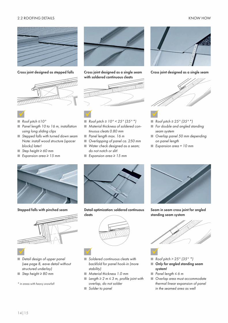
Detail design of upper panel ■
(see page 8, eave detail without structured underlay)Step height ≥ 80 mm ■
Cross joint designed as stepped falls
Seam in seam cross joint for angled standing seam system
Cross joint designed as a single seam with soldered continuous cleats
Roof pitch ≤10° ■
Panel length 10 to 16 m, installation ■
using long sliding clipsStepped falls with turned down seam ■
Note: install wood structure (spacer blocks) later!Step height ≥ 60 mm ■
Expansion area ≥ 15 mm ■
Roof pitch ≥ 10° < 25° (35° *) ■
Material thickness of soldered con- ■
tinuous cleats 0.80 mmPanel length max. 16 m ■
Overlapping of panel ca. 250 mm ■
Water check designed as a seam; ■
do not notch or slit!Expansion area ≥ 15 mm ■
Roof pitch > 25° (35° *) ■
Only for angled standing seam ■
system!Panel length ≤ 6 m ■
Overlap area must accommodate ■
thermal linear expansion of panel in the seamed area as well
Cross joint designed as a single seam
Roof pitch ≥ 25° (35° *) ■
For double and angled standing ■
seam systemOverlap panel 50 mm depending ■
on panel lengthExpansion area = 10 mm ■
Stepped falls with pinched seam Detail optimization: soldered continuous cleats
Soldered continuous cleats with ■
backfold for panel hook-in (more stability)Material thickness 1.0 mm ■
Length ≥ 2 m ≤ 3 m, profile joint with ■
overlap, do not solderSolder to panel ■
* in areas with heavy snowfall

KNOW HOW 2.3 FAÇADE CLADDING
RHEINZINK-Angled Standing Seam System
Ventilated substructure 1 Wood design
Ventilated substructure 2Metal Design
1 Thermal insulation
2 Wooden batten
3 Ventilation space
4 Wooden sheathing
5 Angled standing seam system
Surfaces: “preweathered ■ pro blue-grey“ and ”preweathered pro graphite-grey“Coil width: 500 mm ■
Material thickness: 0.8 mm ■
Optimum aesthetics when using sheets ■
Always produce wall claddings from ■
the same batch in order to avoid colour discrepancies
1 Thermal insulation
2 Bracket system made of metal with thermal
break
3 Ventilation space
4 Trapezoidal profile
5 Underlay (buffer)
6 Angled standing seam system
Sheet material preferred ■
Angled standing seam system ■
coil width 500 mm x 0.8 mmPanel length ≤ 6 m (handling) ■
Always fabricate panels and ■
adapter panels from the same batch (colour discrepancies!)Panel fastening – see “Roofing – ■
Double Standing Seam System“Wooden sheathing 100 mm x ■
24 mm or suitable OSB/BFU-boards, 22 mmVentilation space ≥ 20 mm ■
Thermal insulation ■
(as per country standard)Windproofing is done on site! ■
Fix panel on ridge, length of fixed ■
clip area – 1 m
Sheet material preferred ■
Angled standing seam system ■
coil width 500 mm x 0.8 mmPanel length ≤ 6 m (handling) ■
Always fabricate panels and ■
adapter panels from the same batch (colour discrepancies!)For panel fastening, see “Roofing – ■
Double Standing Seam System“ – using suitable rivets/screws Use suitable underlay as a buffer ■
Trapezoidal profile, galvanized ■
steel with/without coating – type of profile depends on wind loadMetal substructures are used as ■
fasteners Ventilation space ≥ 20 mm ■
Thermal insulation ■
Windproofing is done on site! ■
Fix panel at ridge point, length of ■
fixed clip area: 1 m
RHEINZINK-Tile Systems
Surfaces: “preweathered ■ pro blue-grey“ and ”preweathered pro graphite-grey“Standard size: 333 mm x 600 mm ■
und 400 mm x 800 mm (other sizes are available)Material thickness: 0,7, 0,8 and ■
1,0 mm
~ 13 mm
3-5 mm
~ 2
5 m
m
1234
5
12
3456
Vertical section Horizontal section Vertical section Horizontal section

KNOW HOW2.4 FAÇADE CLADDING DETAILS
16|17
This is the result of unprofessional ■
craftsmanship and lack of planning. A design using only one coil ■
width is seldom possible.Change of seam is not designed. ■
Soffit/lintel overlap is a sloppy ■
detail
Coping should be full-surface ■
bonded with Enkolit®, in order to prevent drumming sounds!Indirect fastening using continuous ■
cleats is required if the leg height is ≥ 50 mm
Window opening with symmetrical segmentation
Panel width change up to ca. 50 mm ■
is not discernable visually Seam should always be used at ■
jamb locations If cross joints are used, these should ■
be in the lintel area No soldering work around window ■
sills. Traces left by soldering fluid cannot be repaired
Window sill coping
Lintel
Air intake through perforated sheets ■
or stamped openings in lintel profiles Lintel attached to window frame us- ■
ing receiver strips Surface connection flush with edge ■
of eave
Assymetrical window opening
Jamb
Angled standing seam designed at ■
jamb connectionConnect jamb to window frame us- ■
ing a receiver strip No direct fastening using screws or ■
nailsDo not solder window sill coping to ■
jamb
Symmetrical design ■
Stable solution to prevent arching of ■
corner panels
Corner of Building

KNOW HOW 2.5 ROOFING AND ACCESSORIES
Snow Guard System S5
Latchways Roof Anchor Type 65618-00Fall protection for craftsman working on standing seam roofs
Do not use galvanized components ■
(risk of rust formation)Do not use snow guard clamps that ■
are too narrow (cracks as a result of construction errors and installation in seam area)As a rule, install one snow guard ■
clamp per seam
Guides force directly into the con- ■
struction without damaging the panel Fastened to the standing seam using ■
S5 brackets – without penetration Coil in roof anchor dampens dy- ■
namic forces Allowed for eave and verge load ■
according to DIN 4426
Fasten clamping brackets to double ■
standing seams Can be used for roof pitch of ≤ 40° ■
Retainers for roof stepsLightning Protection SystemEave design with flexible brackets
Lightning protectionFix panel on point of eave = expansion cracks on panel
InstalI ice guards to prevent sheet ice ■
from falling Install 1 to 2 ice guards per panel, ■
as requiredDo not use fasteners made of galva- ■
nized steel (risk of rust formation)
Ice guards for snow guard system
Snow guard systemThe clamp has to allow thermal length expansion of the tube.
Use lightning protection clamps ■
made of aluminum wrought alloy Flexible connecting wires can ac- ■
commodate changes in panel length Arrester devices should be placed ■
every ca. 20 m as per specificationsMetal roof surfaces function as ■
outer lightning protection, if there is grounding

KNOW HOW2.6 JOINTING TECHNIQUES
18|19
Soft solderingSoft soldering is an impervious solid con-nection performed in one operation
Flux for soft soldering Coat the RHEINZINK-surface
Proper handling of hammer bit
Alloy formation
Continuous alloy formation
Solder protective coating
Texture of solder
The following steps are to be taken into account to create a proper, profession-ally soldered seam:
Preparation: Clean dirty surfaces manually or ■
with chemicals Sheet metal overlap ≥ 10 mm ■
≤ 15 mmUsing a brush, apply flux full-surface ■
and generously to the parts to be connected
Soldering process:Hammer bit > 350 g, preferably ■
500 gWorking temperature ca. 250 °C ■
Soldered gap ≤ 0,5 mm, the nar- ■
rower the soldered gap, the stronger the soldered seam Using the pre-tinned hammer edge, ■
heat the parts to be joined to melting temperature The solder will be melted on the ■
soldering bit in the amount required Soldering tin S-Pb60Sn40, (low in ■
antimony) penetrates the soldering gap with capillary action Pre-tin metal if metal thickness is ■
> 0.8 mm Finishing:
Remove residual flux with a damp ■
cloth = this is important aesthetically (see RHEINZINK-Soldering Instruc-tions)
Guide soldering iron, thoroughly ■
solder overlapHeat to right temperature ■
(ca. 250°C)Solder using even speed ■
Wrong soldering bit (pointed ■
soldering bit)Overheated bit ■
Soldering too quickly ■
Insufficient weight = insufficient ■
heat transferUnsuitable flux (acid, etc.) ■
Overlap of metal parts too big ■
Soldering temperature too cold ■
Do not leave profile joints for ■
days without soldering (dirt re-duces strength of soldered seam)
Sources of error when soft soldering
Apply flux
Apply flux
Clean substructure ■
Full-surface application of Enkolit ■ ® using a notched trowelCreate joints using butt straps or ■
UDS connectors For vertical legs ≥ 50 mm, continu- ■
ous cleats should be used
The permanently elastic bituminous adhesive, Enkolit®, has been used suc-cessfully in sheet metal technology for 40 years.For proper usage, please see installa-tion instructions provided by Enke for Enkolit®.
Adhesive bonding of copings
Removes oxide residue and rolling ■
emulsion Soldering flux is discharged ■
Suitable for bright-rolled and ■
“preweathered pro blue-grey“: liquid flux ”ZD-pro“ by FelderSuitable for “preweathered ■ pro graphite-grey“: solvent + liquid flux “ZD-pro“ (pre-clean manually or by using chemicals)

KNOW HOW 2.7 ROOF DRAINAGE SYSTEMS AND COPING
Surfaces: bright rolled, ■
“preweathered pro blue-grey“, ”preweathered pro graphite-grey“It’s always a good fit: our complete ■
roof drainage system consists of over 500 parts. Just ask!
RHEINZINK-Roof Drainage System
Maximum distance for expansion elements
RHEINZINK-Coping
Surfaces: bright rolled, “preweath- ■
ered pro blue-grey“,“preweathered ■ pro graphite-grey“ (Profile up to max. 700 mm cut length)Material thickness: 0.8 mm ■
(as a rule)Connect profile lengths properly and ■
professionally Lateral inclination ≥ 3° ■
Fasten indirectly using continuous ■
cleats or through adhesive bonding using Enkolit®
Connections and Expansion Elements
Soft Soldering and Expansion Ele- ■
ments (industrial)
UDS-Connectors (industrial) ■
Flat Expansion Joint (manually) ■
Single Seam (manually) ■
* cut max. distance in front of corners and other fixed-points in half!
Gutters, half-round or box-shaped
Material thickness for standard sizes ■
≤ 333 mm = min. 0.7 mmMaterial thickness for standard sizes ■
≥ 400 mm = min. 0.8 mmStandard sizes: 200 mm, 250 mm, ■
280 mm (only for half-round gut-ters), 333 mm, 400 mm, 500 mmStandard length: 3 m ■
Fasten with suitable gutter brackets: ■
RHEINZINK covered or galvanizedFasten with proven snap-lock ■
bracket system made of aluminum die castingClearance of gutter bracket/snap- ■
lock bracket or bracket retainer: ≥ 50 cm ≤ 90 cmSoft solder profile joint ■
Expansion elements – see Table ■
Downpipe, roundDownpipe according to DIN EN 612 ■
Material thickness for standard sizes ■
≤ 60/80 mm = 0.65 mm Material thickness for standard sizes ■
≥ 100/120/150 mm = 0.7 mmAll pipe sizes are high frequency ■
welded Standard length: 2 m or 3 m, ■
Fasten with RHEINZINK-Downpipe ■
Bracket or RHEINZINK-Universal-Downpipe Bracket
2
3
4
9
10
1 Half-round gutter
2 Eaves profile
3 Leaf guard
4 Fixing rail/snap-lock
bracket system
5 Stopend
6 Gutter corner
7 Plug-in outlet
8 Extended pipe bend
9 Pipe bend
10 Universal-downpipe brack-
et with lightning conductor
clamp
11 Rainwater collector
12 Patented high-frequency
welded downpipe
13 Cover sleeve
14 Standpipe
4
11
12
13
14
5
6
8
71
Gutters Standard size/cut length max. distance (m)* for expansion elements
Bracket-mounted gutters ≤ 500 15.0
Edge gutter > 500 8.0
Valley gutters (not glued in place) > 500 8.0
Shed roof gutters > 800 6.0
Building profiles fastened indirectly all standard sizes 8.0
Building profiles – glued in place all standard sizes 6.0
* Te
rms
and
cond
ition
s of
gua
rant
ee o
n re
ques
t

10
46
63
-RZ
-GB
_STA
MM
-00
7-1
2-1
2
RHEINZINK GmbH & Co. KGPostfach 145245705 DattelnGermany
Tel.: +49 2363 605 - 0Fax: +49 2363 605 - 209