standing device for a six year old student
TRANSCRIPT
i
MQP AHH-1401
Standing Device for a Six Year Old Student
April 29, 2015
A Major Qualifying Project Proposal
Submitted to the Faculty
Of the
Worcester Polytechnic Institute
In partial fulfillment of the requirements for the
Degree of Bachelor of Science
In Mechanical Engineering
By:
Collin Glynn
Michael Guarino
Juan Ordonez
Zhaoyu Zheng
_______________________ _______________________
Professor Allen H. Hoffman Professor Holly K. Ault
Mechanical Engineering Mechanical Engineering
i
Abstract A six-year-old student with cerebral palsy is unable to stand on her own due to her condition
which inhibits control of motor skills and hinders muscular development. While several commercial
standing devices currently exist, these devices do not accommodate for knee flexion and therefore
are ineffective for this student. The goal of this project was to design and manufacture an easily
operable standing device tailored to her specific needs and school environment. The device will
accommodate her growth over the next five years and allows for a wide range of adjustability of both
angle inclination of the user’s body as well as the angle support of knee flexion. Initial field tests were
successful and the device was met with great satisfaction from the client and her physical therapist.

ii
Authorship This report represents the cumulative work of Collin Glynn, Michael Guarino, Juan Ordonez
and Zhaoyu Zheng. All members of the team contributed to the completion of the project and the
accompanying report.
iii
Acknowledgements This completion of this project was achieved successfully due to the support of a number of people
throughout its duration:
Sally Goodhile, PT and the Roosevelt Elementary School – Project Sponsors
Professor Allen Hoffman and Professor Holly Ault – Co-Advisors
Mikhail Tan – WPI Machine Shop
Barbara Fuhrman – Mechanical Engineering Department

iv
Table of Contents Abstract ........................................................................................................................................... i
Authorship ...................................................................................................................................... ii
Acknowledgements ....................................................................................................................... iii
Table of Contents……………………………………………………………………………………………………………………v
List of Figures ............................................................................................................................... viii
List of Tables .................................................................................................................................. ix
Chapter 1: Introduction ..................................................................................................................1
Chapter 2: Background ...................................................................................................................2
2.1 Spastic Cerebral Palsy ................................................................................................................. 2
2.1.1 Impact on Development ...................................................................................................... 2
2.1.2 Treatment ............................................................................................................................ 4
2.2 Standing Devices ......................................................................................................................... 5
2.2.1 Prone Standers .................................................................................................................... 5
2.2.2 Supine Standers ................................................................................................................... 6
2.2.3 Vertical Standers ................................................................................................................. 7
2.2.4 Sit-to-Stand Standers .......................................................................................................... 7
2.2.5 Mobile Standers ................................................................................................................... 8
2.3 Needs Assessment ....................................................................................................................... 8
2.3.1 Condition of the Client ............................................................................................................... 9
2.3.2 Description of the School and the Classroom .......................................................................... 9
2.3.3 Current and Previous Devices used by the Client .................................................................. 10
2.3.4 Client’s Abilities and Physical Attributes ............................................................................... 11
Chapter 3: Goal Statement: ........................................................................................................... 14
Chapter 4: Design Specifications .................................................................................................. 14
4.1 Functional ........................................................................................................................................ 14
4.2 Stability and Support ...................................................................................................................... 14
4.3 Ergonomics ...................................................................................................................................... 15
4.4 Transfer ............................................................................................................................................ 15
4.5 Operability ....................................................................................................................................... 15
4.6 Transportability .............................................................................................................................. 16
4.7 Safety ................................................................................................................................................ 16
4.8 Maintenance .................................................................................................................................... 16
v
4.9 Manufacturing ................................................................................................................................. 16
4.10 Materials ........................................................................................................................................ 16
Chapter 5: Functional Decomposition ......................................................................................... 18
5.1 Balance and Safety .......................................................................................................................... 18
5.2 Adjustability..................................................................................................................................... 18
5.3 Transportability .............................................................................................................................. 18
Chapter 6: Preliminary Design Process ....................................................................................... 19
6.1 Morphological Chart ....................................................................................................................... 19
6.1.1 Body Support ............................................................................................................................ 19
6.1.2 Head/Neck Support ................................................................................................................. 19
6.1.3 Knee Flexion ............................................................................................................................. 19
6.1.4 Ankle Flexion ............................................................................................................................ 20
6.1.5 Growth Adjustability ................................................................................................................ 20
6.1.6 Lift Assistance ........................................................................................................................... 20
6.1.7 Adjustability of Lift Assistance ................................................................................................ 20
6.1.8 Stability ..................................................................................................................................... 20
6.1.9 Transportability ....................................................................................................................... 20
6.2 Creation of Design Alternatives ..................................................................................................... 20
6.2.1 Design 1 ..................................................................................................................................... 21
6.2.2 Design 2 ..................................................................................................................................... 24
4.2.3 Design 3 ..................................................................................................................................... 25
4.3 Design Selection .............................................................................................................................. 26
4.3.1 Decision Matrix ......................................................................................................................... 26
4.3.2 Feedback from Physical Therapist .......................................................................................... 27
Chapter 7: Final Design................................................................................................................. 29
7.1 Iterations and Changes made to Design ........................................................................................ 29
7.1.1 Replacement of thigh board with knee board ........................................................................ 30
7.1.2 Placement of the screw rod ..................................................................................................... 30
7.2 Final Design Decomposition ........................................................................................................... 31
7.2.1 Frame Assembly ....................................................................................................................... 31
7.2.2 Board Assembly ........................................................................................................................ 32
7.2.3 Other components .................................................................................................................... 36
7.3 Detailed Analysis ............................................................................................................................. 37

vi
7.3.1 Statics Analysis ......................................................................................................................... 37
7.3.2 Stress Analysis .......................................................................................................................... 39
Chapter 8: Manufacturing ............................................................................................................ 42
8.1 Frame Assembly .............................................................................................................................. 42
8.1.1 Base ........................................................................................................................................... 42
8.1.2 Central Beam ............................................................................................................................ 42
8.2 Front Board Assembly .................................................................................................................... 44
8.2.1 Assembly of Boards .................................................................................................................. 44
8.2.2 Padding ..................................................................................................................................... 46
8.2.3 Straps ........................................................................................................................................ 46
8.2.4 Lateral Supports ....................................................................................................................... 46
8.3 Tray and Tray Connector ................................................................................................................ 47
8.4 Front Board Angle Adjuster/Support ............................................................................................ 48
8.4.1 Telescoping Tube Mechanism ................................................................................................. 48
Chapter 9: Verification and Testing ............................................................................................. 49
9.1 Safety and Stability .......................................................................................................................... 49
9.2 Adaptability and Ease of Operation ............................................................................................... 50
9.3 Comfort ............................................................................................................................................ 51
9.4 Transportability .............................................................................................................................. 53
9.5 Miscellaneous .................................................................................................................................. 53
Chapter 10: Results and Discussion ............................................................................................. 54
10.1 Functionality Testing .................................................................................................................... 54
10.1.1 Effective Range of Motion ...................................................................................................... 54
10.1.2 Support of Loading ................................................................................................................. 54
10.2 Integration within User Environment ......................................................................................... 54
10.2.1 Classroom and Caregiver Interaction ................................................................................... 55
10.2.2 User Interaction ..................................................................................................................... 55
10.3 Physical and Social Development ................................................................................................ 55
Chapter 11: Future Work ............................................................................................................. 56
Chapter 12: Conclusion................................................................................................................. 57
Bibliography .................................................................................................................................. 59
Appendices .................................................................................................................................... 60
Appendix A: Decision Matrix used on Preliminary Designs ............................................................... 60

vii
Appendix B: Free Body Diagrams and Static Analysis of Final Design.............................................. 61
Appendix C: Statics Analysis Calculations ........................................................................................... 68
Appendix D: Stress Analysis Calculations............................................................................................ 71
Appendix E: Prototype testing Protocols ............................................................................................ 80
Appendix F: Part Drawings ................................................................................................................... 85
Appendix G: Photos of Client and Device ............................................................................................. 92
Appendix H: User Manual for Final Device .......................................................................................... 94

viii
List of Figures Figure 1: Prone stander manufactured by Rifton (Rifton 2014). ........................................................................ 5
Figure 2: Rifton Prone Stander Height Adjustment (Rifton 2014). .................................................................... 6
Figure 3: Rifton Prone Stander Inclination Adjustment (Rifton 2014). ............................................................ 6
Figure 4: Supine Stander manufactured by Rifton (Rifton 2014). ...................................................................... 7
Figure 5: Vertical Stander by Patterson Medical (Patterson 2013). .................................................................. 7
Figure 6: Felicity's Sit-to-stand Device. .......................................................................................................................... 8
Figure 7: Sit-to-stand device by Altimate Medical (Altimate Medical, 2012). .............................................. 10
Figure 8: Felicity's Rifton Gait Trainer (Rifton 2014). ........................................................................................... 10 Figure 9: Felicity using a Prone Stander. ................................................................................................................... 13
Figure 10: First iteration of Design 1. ........................................................................................................................... 21
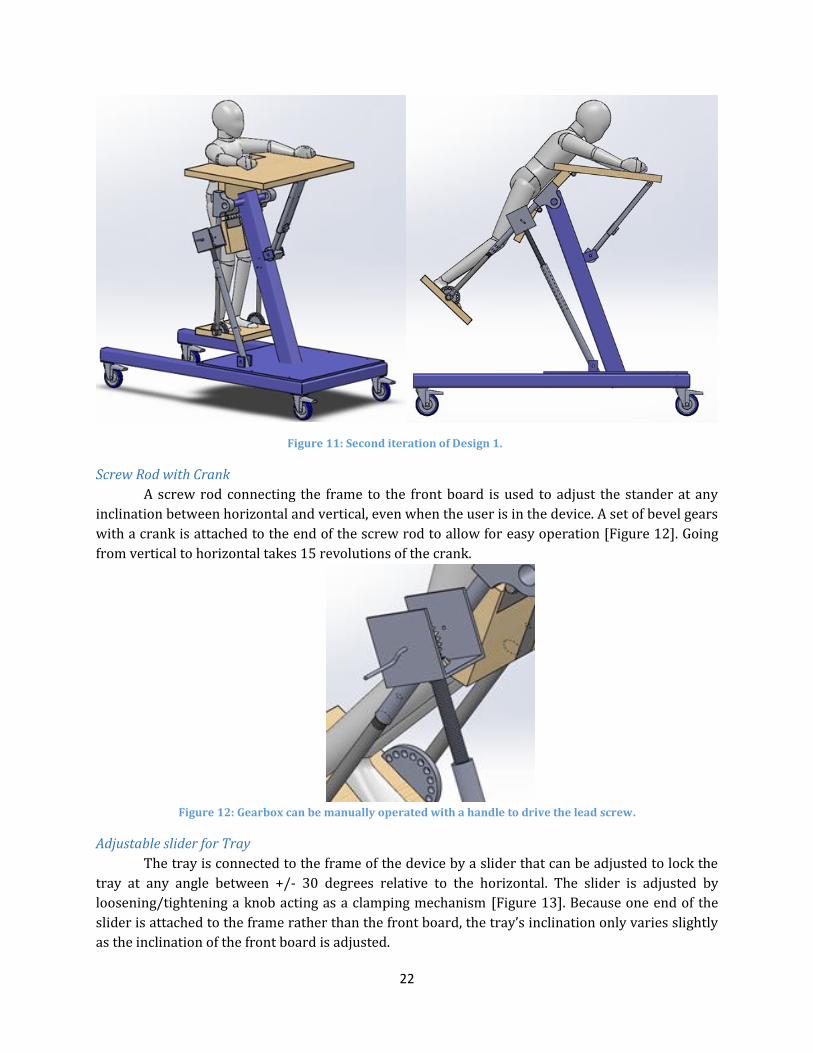
Figure 11: Second iteration of Design 1. ...................................................................................................................... 22
Figure 12: Gearbox can be manually operated with a handle to drive the lead screw. ............................ 22
Figure 13: The slider's length can be adjusted to change the inclination of the tray. ............................... 23
Figure 14: Thigh board adjusted at a position enabling the user to flex the knees. .................................. 23
Figure 15: Footboard can pivot around an axis to enable ankle flexion. ........................................................ 24
Figure 16: Design 2. .............................................................................................................................................................. 24
Figure 17: Air spring used for design 2. ....................................................................................................................... 25
Figure 18: Scissor Jack used in Design 2 to provide growth adjustability. .................................................... 25
Figure 19: Design 3. .............................................................................................................................................................. 25
Figure 20: Lever system used in Design 3 to provide lift assistance. .............................................................. 26
Figure 21: Office Chair Lift used in Design 3 to provide growth adjustability. ............................................ 26
Figure 22: Final Design........................................................................................................................................................ 29
Figure 23: The kneeboard supports the lower half of the user’s legs.............................................................. 30
Figure 24: The screw rod is now placed in the middle of the device. .............................................................. 30
Figure 25: Isometric view of Frame Assembly. ......................................................................................................... 31
Figure 26: Base frame made of square tubing. .......................................................................................................... 31
Figure 27: Side view of Central Beam. .......................................................................................................................... 32
Figure 28: Lockable hinges and steel plates are used to connect the front and kneeboards. ............... 34
Figure 29: Tube connecting the screw rod to the front board. ........................................................................... 34
Figure 30: Bearings are used to connect to a pin on the central beam to allow the Front Board to
pivot. ........................................................................................................................................................................................... 35
Figure 31: Telescoping tubes connecting the footboard with the kneeboard. ............................................ 35
Figure 32: Mechanism used to adjust and lock footboard at different angles. ............................................ 36
Figure 33: Screw Rod Mechanism. ................................................................................................................................. 36
Figure 34: Isometric view of tray. ................................................................................................................................... 37
Figure 35: Side-view of tray connector. ....................................................................................................................... 37
Figure 36: Joints (Letters on Diagram) whose forces were identified after statics analysis. ................ 38
Figure 37: Results of stress analysis of critical components of the design. ................................................... 40
Figure 38: Results of stress analysis of critical components of the design (Continued). ........................ 41
Figure 39: T-Bracket Assembly........................................................................................................................................ 42
Figure 40: Base Plate Assembly. ...................................................................................................................................... 43
Figure 41: Center Beam Pivoting Connection. ........................................................................................................... 44
Figure 42: Sample of counter-bore Holes constructed within the front board. .......................................... 44
Figure 43: Hinge Assembly connecting front board and thigh board. ............................................................. 45
Figure 44: Underside view of bearing assembly responsible for supporting footboard. ........................ 45
ix
Figure 45: Arch-Shaped Pin Locking Mechanism. .................................................................................................... 46
Figure 46 Lateral Supports to Secure User ................................................................................................................. 47
Figure 47: L Brackets and Tray Connection. .............................................................................................................. 47
Figure 48 Device showed no signs of risk or danger when loaded with weight plates adding up to
120 lbs. for an hour ............................................................................................................................................................... 49
Figure 49: The front board (45° angle with ground) supports the upper body and the thighs; the
kneeboard supports the lower portion of the knees and the shins; the footboard supports the user’s
feet. .............................................................................................................................................................................................. 52
Figure 50: Felicity using device with the front board at a 45° angle. .............................................................. 52
Figure 51: Client Performing Activities On Device. ................................................................................................. 57
Figure zz Client showing positive reactions while using the standing device ............................................. 92
Figure aaa A front board inclination closer to horizontal minimizes the weight bared by the user .. 93
Figure bbb The device was tested prior to putting the client on it to ensure it was safe to use .......... 93
List of Tables Table 1: Basic Anthropomorphic Measurements for Felicity (1/28/2015) ................................................. 11
Table 2: Range of Motion Measurements for Felicity (1/28/2015) ................................................................. 12
Table 3: Body Circumference Measurements (1/28/2015). ............................................................................... 12
Table 4: Weight Support Measurements. .................................................................................................................... 13
Table 5: Morphological Chart used for Primary Designs ...................................................................................... 19
Table 6: Final Decision Matrix. ......................................................................................................................................... 27
Table 7: Values of critical loads at three different angles of inclination. ........................................................ 39
Table 8: Cost of Project Device Compared to Retail Prices of Commercial Devices. ................................. 57

i
Chapter 1: Introduction The client, around whom this project has been designed, is a six-year-old student enrolled in
the Worcester public school system. She has been diagnosed with a spastic form of cerebral palsy,
preventing the average muscular development expected for a child her age. The condition also
inhibits her motor control, preventing the student from standing in an upright position under her
own power. Despite the abundant physical limitations she faces on a regular basis, the student
participates with the remainder of her class as much as possible, even attending gym and music
classes with her peers. Although aware of her condition, the student displays a permanently
contagious smile, bringing happiness to each of the members of the school staff with whom she comes
in contact.
In order to allow for her aided navigation throughout the school, as well as to and from the
school bus each day, the client has an assistive stroller, in which she spends the majority of the day.
The stroller has been outfitted with an anterior tray that allows her to complete classroom activities
without requiring a desk like her fellow classmates. She is relocated about the school while remaining
in her stroller at the discretion of her schedule. Although the benefits offered by the use of the stroller
may quantitatively outnumber those of a different device, this is certainly not true under qualitative
speculation. Due to the convenience and level of comfort provided by her stroller, however, the
student spends most of her day in a seated position, further hampering the muscular development of
her lower extremities.
There exist a variety of assistive standing devices within the room of the school utilized by
the physical therapist that regularly meets with the student. The devices remain in this room, and are
only used by the student under the close supervision of her therapist. In addition, she does not spend
much time at all using any of the devices due to the level of discomfort they create for her, due to the
fact that they fail to accommodate the specific attributes unique to her condition. This further
compels her school-day caregivers to leave the student in her stroller.
The lack of an assistive standing device that caters to the specific needs of this student has
required the development of this project. In order to properly assist muscular development within
her legs, the client requires a device that will allow her to stand in a supported position, ideally
containing a variant degree of assistance to be utilized as she gradually develops the strength to
support herself. The device must accommodate adjustable angles of flexion within all major joints of
the lower body – hips, knees, and ankles.
2
Chapter 2: Background In order to successfully complete the project, it was essential to develop a thorough
understanding of the client’s condition, as well as the unique details of her condition requiring a
personally designed device. Research was conducted on the client’s condition and current standing
devices. Several meetings were held with the client and her physical therapist in order to obtain
specific information involving Felicity and her environment. The following sections encompass the
main outcomes of the research, with additional details presented in the appendix.
2.1 Spastic Cerebral Palsy Cerebral Palsy, often referred to as CP, is a condition that brings permanent disorders of
growth accompanied with disturbances of sensation, perception, cognition, communication,
behavior, as well as epilepsy and secondary musculoskeletal problems. This condition is caused by
non-progressive disturbances, which occur during the development of the fetal or infant brain
(Rosenbaum, 2006). CP is considered to be the most common cause of serious physical disability in
childhood, affecting 2 to 3 babies per 1000 births. The earliest indications of cerebral palsy can be
difficult to properly interpret, due to the unpredictable development of an infant. Infants may display
spasticity of specific muscles or seizures as an early sign of the condition. There are, however, less
detectable signs, which may go unnoticed by parents for as long as a year. In more mild cases,
newborn children may exhibit reliance on one side of their body, difficulty with sucking and
swallowing, and a lack of energy. Each case of cerebral palsy is different, and each child may
demonstrate different disabilities brought by the condition. CP is categorized into five classes:
spastic, dyskinetic, ataxic, hypotonic, and mixed.
The client, Felicity, has been diagnosed with spastic CP. This is the most common type, affecting
about 70 to 80% of all persons diagnosed with CP. A characteristic of spastic cerebral palsy is stiffness
and tightness in muscle groups, caused by damage to the outer layer of the fetal or infant brain. This
maintains substantially negative effects on muscles and joints, disrupting normal growth throughout
childhood. Likewise, spastic CP can be broadly explained as a combination of orthopedic and
neuromuscular issues; this means that, in addition to stiffness and tightness of muscle tones, the
condition also leads to different levels of difficulties in communication skills. However, it remains
unclear how the cognitive abilities of a person with spastic CP are affected by the developmental
complications incited by the condition. Our client is non-verbal but able to understand conversations,
displaying sensitivity and responsiveness during interactions with other individuals. Her exact level
of cognitive skill remains unknown. Spastic CP can cause various types of deformities over time, but
this is largely dependent upon the severity of the condition. Felicity’s form of CP has affected her
knees, ankles and arms, limiting her overall mobility.
2.1.1 Impact on Development
Physical Development:
Cerebral Palsy is “an umbrella term covering a group of non-progressive, but often changing,
motor impairment syndromes secondary to lesions or anomalies of the brain arising in the early
stages of its development” (Wood, 2006). The condition often manifests itself in the presence of a
substantially reduced amount of posture control. Although the skills may be acquired later than those

3
without the condition, children with Cerebral Palsy typically develop the ability to control direction-
specific activity. Difficulties typically arise with actions that do not involve progressive movement.
These areas include maintaining control of their own bodyweight and establishing the simplest
senses of balance.
The condition can affect the development of the entire skeletal system and is a common cause
of progressive musculo-skeletal deformity. Subject to unnatural movements due to the
underdeveloped skeletal system, individuals with Cerebral Palsy unavoidably subject their bodies to
different strains than would a healthy complement. The change in biomechanical forces due to CP
can often lead to the progressive dislocation and deformity of a joint (Turner, 2013).
The physical limitations to typical physiologic maturity common among children with CP at
the elementary school age collectively serve to delay the development of motor skills. As they
continue to age and develop, children living with physical disabilities often experience an increasing
regression in their functional abilities. The basic motor skills affected by this phenomenon include
crawling, standing, sitting, or walking without assistance. The difficulty in performing these tasks can
be attributed to limited ranges of motion and poor muscular control.
Cognitive Skills:
Along with the physical impairments characteristic of this condition, Cerebral Palsy can
disrupt the intellectual growth of a child. This can be due to underdevelopment within the brain of
the child, or simply development at a much slower pace. This greatly complicates the process of
learning and interacting within the educational system. Children with Cerebral Palsy often
experience symptoms of speech impairments, memory loss, and can struggle with the most
rudimentary forms of comprehension.
Testing the cognitive ability at such a young age is fairly difficult, but this process becomes
significantly more complex when the child is unable to effectively communicate thoughts or
understand what is being asked of them. Therefore, the cognitive abilities of children with CP can be
even more difficult to evaluate.
Social Abilities:
The social and psychological toll of a developmental condition upon the affected individual is
often an area that remains overlooked when analyzing the impacts of the condition. Along with the
physical impairments characteristic of the condition, those with Cerebral Palsy often display signs of
social impairment. Children with CP are at risk for worse social outcomes, including decreased social
functional capability, smaller friendship networks, poorer quality friendships, and reduced social
participation (Whittingham, 2010).
As the average child progresses through his/her childhood and teenage years, they become
increasingly less dependent upon their parents for support. This is not the case among children with
Cerebral Palsy. This population of children remains dependent upon constant assistance from others
well into, and often including, adulthood. Studies conducted comparing healthy students and those
with Cerebral Palsy have shown that, although it is not often, Cerebral Palsy can cause reduced values
of self-esteem in those affected (Manuel, 2003). Throughout the preliminary contact made with the
4
client, Felicity, along with confirmation for her PT, it is apparent that she is not affected by this
phenomenon.
2.1.2 Treatment
Cerebral Palsy is a condition caused by permanent damage and therefore treatments are
aimed at mitigating the effects of the damage. Such treatments often relax the tightness and stiffness
in muscle groups, aimed at lessening the negative effects of spasticity. Unfortunately, cases in which
treatment completely relieves individuals of this spasticity are very rare. Nonetheless, treatment
promises the possibility of a drastically more independent life.
Treatment of spastic CP is based on careful evaluation of the relative strength of certain
muscles against their antagonists and is often conducted in rehabilitation centers. Sequential tests
are performed to obtain a more thorough understanding for each specific case of CP. Based on the
results of these tests, each patient is provided a personalized plan aimed at alleviating his or her
unique symptoms, generally including a variety of stretches.
In addition to the adoption of physical therapy plans, patients also have access to many
practical and efficient drug therapies used for spastic CP. Valium and baclofen two of the most
commonly prescribed oral medications. Valium, also called diazepam, affects chemicals in the brain,
which often reduces spasticity by relaxing the patient (Drugs.com 2014). Baclofen, on the other hand,
is a type of agonist that functions at the spinal cord level to impede the release of excitatory
neurotransmitters that cause spasticity (Neurol 1996). Neither oral medication, unfortunately, has
been shown to substantially stifle spasticity among individuals with CP. The use of Botox injections
at the site of muscular stiffness is a more effective method, weakening muscles and consequently
lowering the levels of spasticity they experience. Effects of this treatment can last up to 3 to 4 months
per injection with minimal side effects. A final alternative is surgery; orthopedic surgery decreases
spasticity by stretching tendons and releasing muscles (Zeiter 1946). Methods of performing
orthopedic surgery on a patient depend on which muscle groups are affected. This surgery for
children with CP should be considered when following conditions appear (Staff 2012):
- A bone or joint deformity that causes pain or interferes with function and is getting
worse over time
- Permanent stiff joints (contracture)
- Dislocated or irregularly functioning joints
- A spinal deformity that is not improving with other treatment
- A deformity that makes some caregiving functions, such as bathing, extremely difficult
or impossible
Numerous articles and studies point to the importance of standing and the physiological
benefits of providing standing therapy to children with special needs. The human body is designed
to be upright, and the bones, muscles, organs and nervous system function best when standing
(Bundonis 2009). When in an upright position, the spine extends and the pelvis moves into an
anterior tilt, providing more space throughout the trunk for organs to function.
Therapists believe that after wheelchairs, standing devices are the assistive technology most
beneficial to children with special needs (Warner 2007). Mark P. Warner, a professional physical

5
therapist and certified brain injury specialist, explains that children with CP are often more likely to
develop scoliosis and joint deformities than other kids. Standing devices help these children maintain
a correct posture, avoiding the need for corrective surgical interventions. For children who cannot
stand on their own, standing devices present even more physiological benefits, as these devices give
them the opportunity to bear weight on their lower extremities as well as to extend their joints. This
facilitates bone and muscle development, preserves range of motion, decreases the effects of
spasticity, and prevents a loss of bone mineral density. In fact, a study conducted among children
with cerebral palsy indicated that participation in longer periods of standing improved their
vertebral bone mineral density and reduced the risk of vertebral fractures (Caulton 2004).
However, standing devices offer more than just physiological benefits to children; they also
bring cognitive and psychological benefits. Standing stimulates the reticular activating system in the
brainstem, which increases natural awareness. This allows for more alert and engaging interactions,
improving learning and development (Bundonis 2009). Additionally, by positioning children at eye
level with their peers, standing devices greatly enhance social interactions and self-confidence.
2.2 Standing Devices There are several different types of standing devices for children, each with different
characteristics for different needs. Most standers fall under 3 classic types: prone standers, supine
standers, and vertical standers. Additionally, there are sit-to-stand standers and mobile standers,
which often take form as one of the three main types with additional functions. In order to
understand what type of device a child needs, it is crucial to understand the specific characteristics
and benefits of each stander.
2.2.1 Prone Standers
Prone standers provide front body support, allowing the user to lean forward [Figure 1]. This
position stretches out hip flexor and leg contractures and allows the user to develop his or her head
control. Prone standers often incorporate a tabletop and encourage both the use of arms and
participation in engaging activities. However, this design puts the user
in a gravity-dependent position due to the fact that the main board
only provides support from the ankles to the chest. All other body
parts, such as the arms and head, are left unsupported against gravity.
The lack of head support is critical because it means that the user must
have sufficient neck control to hold up his or her head. For the same
reason, the majority of prone standers are an effective way of
challenging and further strengthening the user’s neck control.
Most prone standers use straps to support the user at four points: the
feet, the knees, the waist, and the upper trunk. They offer many
adjustable features, such as the height of the straps that support the
upper body of the user and of the footboard. Figure 2 shows how a
Prone Stander from manufacturer Rifton allows the positioning of the
supports and straps to be adjusted with a simple slide mechanism to
fit several user heights and account for growth. With this product (the
small Rifton Prone Stander), the resulting range for user heights is 25
Figure 1: Prone stander manufactured by Rifton (Rifton 2014).

6
to 48 inches. The angle of inclination at which the user is supported is another typical adjustment,
usually allowing for a range of 0 to 90 degrees [Figure 3]. Changing the angle alters the amount of
weight that the user is responsible for supporting on his or her own, which can be helpful if using one
device for different users or if the user progresses and can bear more weight over time.
Figure 2: Rifton Prone Stander Height Adjustment (Rifton 2014).
Figure 3: Rifton Prone Stander Inclination Adjustment (Rifton 2014).
2.2.2 Supine Standers
Supine standers are designed for individuals who do not possess the required strength or
body control to use prone standers effectively. In a supine stander, the user lies on his or her back
against a firm mainboard tilted at an angle suitable for his or her abilities. The mainboard provides

7
support from the heels all the way up to the back of the head as shown [Figure 4]. This makes supine
standers ideal for users with significant musculoskeletal weakness (Noble 2014).
Similar to prone standers, supine standers use straps to
firmly hold the user from the feet, knees, waist, and upper trunk.
Additionally, there is a support for the back of the head to reduce
stress on the neck. Often, this support can be removed if the intent is
to strengthen the user’s neck control. Depending on the
manufacturer, several other adjustable features are offered. In
almost all cases, the angle of inclination of the mainboard can be
adjusted from 0 to 90 degrees to promote gradual progression to a
vertical position. Adjusting the device to a horizontal position makes
transfer from a wheelchair more convenient.
Removable armrests are also a common option and are
useful to encourage body control. As with prone standers, supine
standers often incorporate a tabletop to encourage participation in
engaging activities. Finally, supine standers can accommodate a significant range of user heights. The
small supine stander from Rifton, for example, is suitable for children from 30” to 50” tall.
2.2.3 Vertical Standers
Vertical standers, also known as upright standers, stabilize the user in an upright standing
position. Due to the comparatively basic design of the vertical stander, they are often less expensive,
and require less space (Daigle 1999). These types of standers are typically intended for use by those
with good balance and trunk control. Vertical standers are best suited
for those who have postural insecurity or for developing lateral weight-
shifting skills.
Figure 5 is an image of a Hug Vertical Stander made by
Patterson Medical (Patterson, 2014) This is a basic design of a vertical
stander, which is designed for children between the heights of 30-52
inches tall. All support straps (chest, pelvic, and knees) are fully
adjustable to account for different size users. The segmented supports
can slide up and down along the frame, allowing for a wide range of
heights, while the flexible supports utilize velcro to adjust for different
chest/pelvic/leg circumferences. The simplistic structure of the frame
allows for the user to be strapped in from either the front or back side
of the device for easy transfers. The frame can also be removed from
the base, allowing for easy transportation and storage. The frame is
made out of cylindrical metal tubes and therefore it has no sharp edges, increasing the overall safety
of the device.
2.2.4 Sit-to-Stand Standers
Sit-to-stand standers allow users to transition between the sitting and standing position
either independently or with minimal assistance from an aide. These standers are often implemented
Figure 4: Supine Stander manufactured by Rifton (Rifton 2014).
Figure 5: Vertical Stander by Patterson Medical (Patterson 2013).
8
into the standard prone/supine/vertical designs. There are two main types of transfers, those that
use a seat and those that use straps (Daigle, 1999). The sit-to-stand devices that utilize a seat are
designed to be used in a seated position as well as any angle between seated and upright. This allows
the user to gradually build strength to be able to stand in the fully vertical position. The strap-based
devices use one or two straps to lift the user into the upright position. The strap method allows the
user to be transferred from almost any seated device. Sit-to-stand standers are often used for heavier
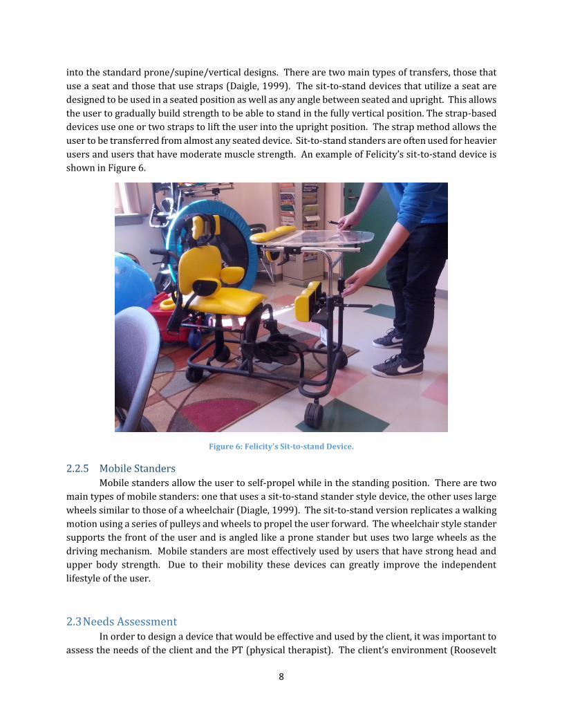
users and users that have moderate muscle strength. An example of Felicity’s sit-to-stand device is
shown in Figure 6.
Figure 6: Felicity's Sit-to-stand Device.
2.2.5 Mobile Standers
Mobile standers allow the user to self-propel while in the standing position. There are two
main types of mobile standers: one that uses a sit-to-stand stander style device, the other uses large
wheels similar to those of a wheelchair (Diagle, 1999). The sit-to-stand version replicates a walking
motion using a series of pulleys and wheels to propel the user forward. The wheelchair style stander
supports the front of the user and is angled like a prone stander but uses two large wheels as the
driving mechanism. Mobile standers are most effectively used by users that have strong head and
upper body strength. Due to their mobility these devices can greatly improve the independent
lifestyle of the user.
2.3 Needs Assessment In order to design a device that would be effective and used by the client, it was important to
assess the needs of the client and the PT (physical therapist). The client’s environment (Roosevelt
9
Public School) as well as the client’s abilities and physical attributes were assessed to better
understand the goal of the project.
2.3.1 Condition of the Client
The client for whom the device was designed, Felicity, has a fairly complicated form of spastic
Cerebral Palsy. Upon meeting with the six-year-old student, the design team was able to gather a
good understanding of her physical limitations.
The spastic nature of the young girl’s condition prevents her from relaxing much of her body.
Her muscles experience constant contractions, which significantly reduces her flexibility, rendering
ordinary tasks near impossible. Felicity remains unable to fully straighten most of her lower
extremities, displaying constant flexure within her ankle and knee joints. The muscle stiffness also
manifests itself in a bowed gait displayed during the use of assistive devices. The condition and its
effects are not confined to the lower portion of her body.
The Asymmetrical Tonic Neck Reflex (ATNR) is a normal characteristic of the human infant
during the first 12 weeks of waking life(Gesell 1938). In Cerebral Palsy patients, however, it is not
uncommon to see a continuation of this postural attitude well into childhood. The habit is
characterized by extension of the arm in the direction of an individual’s head and involuntary flexion
of the opposite arm. Continuation of this routine can interrupt developmental activities, such as
rolling and grasping objects in front of the head, characteristic of this point in growth. The client
currently struggles to overcome the lingering effects of this habit which, coupled with her poor head
control, hinders many of her anterior motor skills.
The effects of reduced muscle control, in addition to their influence upon physical freedoms,
can threaten the physiologic activities of an individual as well. One of these areas is the ability to
communicate freely with others. Felicity, for instance, displays symptoms of a non-verbal case.
Unable to verbally communicate her thoughts, she is reliant upon eye contact and physical gestures
to signal her thoughts to those responsible for providing constant assistance. Felicity also has a case
of gastro-esophageal acid reflux that complicates her daily activities even further. Common among
some Cerebral Palsy patients, her stomach, a muscle, remains contracted during times that it should
be relaxed, causing a backup of stomach acid.
2.3.2 Description of the School and the Classroom
Roosevelt School is located at 1006 Grafton Street, Worcester, Massachusetts, and is a branch
of the Worcester Public School system. The present school opened in 2000, therefore meets all ADA
codes and provides education from kindergarten to elementary level. It covers an area of 121,000
square feet. The hallways inside the building are wide, approximately 6 feet wide, and would allow
for easy turnings between hallways for a 30in wide standing device. Elevators and stairs are both
available from floor to floor. The elevators can fit 2 normal wheelchairs. Finally, the school has
allocated a large room for storing assistive devices.

10
2.3.3 Current and Previous Devices used by the Client
The client has tried a variety of devices to help her stand, but none have been entirely
successful. Analyzing how these devices work and why they have failed to satisfy the client will give
us a better understanding of her needs.
The Altimate Medical’s EasyStand Magician
[Figure 7] is a sit-to-stand device designed to
accommodate individuals ranging between 3’ and 4’ 6’’
tall and that weigh up to 100 lbs. (Altimate Medical Inc
2003). The device features a planar seating system
along with an adjustable tabletop. The table can be
moved in the horizontal and vertical direction and has a
padded edge to allow the table to double as added
frontal support.
The seat includes several adjustable straps and
supports to secure the user. Both the back angle and seat
depth are adjustable using pin slots in order to allow for
any body type. Two pelvic guides, on the left and right
sides of the seat, provide additional hip support. Two independent kneepads are attached to the front
of the frame to provide additional leg stabilization and to accommodate for knee contractures. There
are also two independent footplates which can be adjusted in three directions: plantar/dorsi, toe-
in/toe-out, and forward/aft. The device also has an optional head support accessory in order to
compensate for the user’s diminished neck strength. The device uses a hydraulic system to raise and
lower the seat in an inclined position. The hydraulic system can be operated by pressing a lever on
the base of the unit while gently lifting the handles located on the back of the seat. The seat is
supported by a linkage system that causes the seat to rotate from the horizontal position to the
vertical position as the hydraulic system raises the seat up. This motion can be stopped at any time
allowing for any angled position of the seat.
According to the physical therapist, this device did not work effectively for the client because
it did not provide enough head support to allow her to hold her head against gravity. Moreover, the
client did not respond well to the sit-to-stand motion due to her spasticity. The device did not provide
the support needed and she did not enjoy the
experience overall.
The second device currently being used by the
client is the Rifton Pacer Gait Trainer [Figure 8].
Although this device is not a stander, it allows the user
to function in the upright position. Rifton has a wide
range of model sizes; the device currently being used
by the client is the K051, Small Pacer. This size is
designed for children with elbow heights between
18.5-27.5’’ and supports up to 75 lbs. (Rifton 2014).
The basic support structure is similar to that of a
Figure 7: Sit-to-stand device by Altimate Medical (Altimate Medical, 2012).
Figure 8: Felicity's Rifton Gait Trainer (Rifton 2014).
11
walker with a 3 rail base, 3 bar top support and two bars connecting the top to the base. The device
includes a variety of safety features that limit movement while in use. Casters with swivel lock brakes
allow for controllable movement in any direction, variable drag slows down fast-moving clients to
prevent veering and better navigation of corners, and one-way ratchet controls prevent involuntary
backwards motion. The Pacer is designed to fit through 32’’ doorways and adjusts to the user’s
stature in 1’’ increments.
While the basic function of the device is a walker, our client uses several attachments in order
to use it in a sling-supported manner. The device includes a hip positioner that can be used as a safety
sling to reduce the load exerted on the user’s feet. Our client also uses a chest support attachment,
which has the ability to accommodate a wide range of torso sizes. Both the width and angle of the
chest support can be adjusted using knobs and securing straps.
According to the PT, the client enjoys using the gait trainer. She fits comfortably in the device
and is able to propel herself using both feet at the same time, typically in a “bunny hopping” manner.
The PT stressed that this was not a functional method of transportation because she is not strong
enough to control her exact motions. This device currently serves as a good way of providing the
client some standing time.
2.3.4 Client’s Abilities and Physical Attributes
Anthropomorphic, range of motion, and weight bearing measurements were carried out
through a series of six tests.
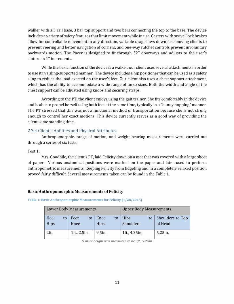
Test 1:
Mrs. Goodhile, the client’s PT, laid Felicity down on a mat that was covered with a large sheet
of paper. Various anatomical positions were marked on the paper and later used to perform
anthropometric measurements. Keeping Felicity from fidgeting and in a completely relaxed position
proved fairly difficult. Several measurements taken can be found in the Table 1.
Basic Anthropomorphic Measurements of Felicity
Table 1: Basic Anthropomorphic Measurements for Felicity (1/28/2015)
Lower Body Measurements Upper Body Measurements
Heel to
Hips
Feet to
Knee
Knee to
Hips
Hips to
Shoulders
Shoulders to Top
of Head
2ft. 1ft., 2.5in. 9.5in. 1ft., 4.25in. 5.25in.
*Entire height was measured to be 3ft., 9.25in.
12
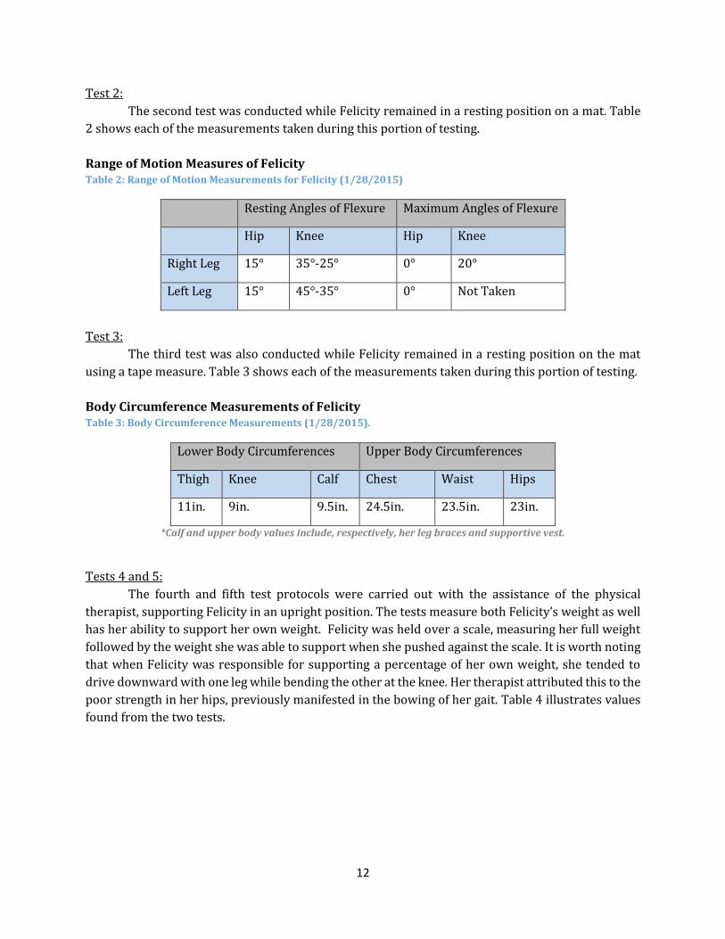
Test 2:
The second test was conducted while Felicity remained in a resting position on a mat. Table
2 shows each of the measurements taken during this portion of testing.
Range of Motion Measures of Felicity Table 2: Range of Motion Measurements for Felicity (1/28/2015)
Resting Angles of Flexure Maximum Angles of Flexure
Hip Knee Hip Knee
Right Leg 15° 35°-25° 0° 20°
Left Leg 15° 45°-35° 0° Not Taken
Test 3:
The third test was also conducted while Felicity remained in a resting position on the mat
using a tape measure. Table 3 shows each of the measurements taken during this portion of testing.
Body Circumference Measurements of Felicity Table 3: Body Circumference Measurements (1/28/2015).
Lower Body Circumferences Upper Body Circumferences
Thigh Knee Calf Chest Waist Hips
11in. 9in. 9.5in. 24.5in. 23.5in. 23in.
*Calf and upper body values include, respectively, her leg braces and supportive vest.
Tests 4 and 5:
The fourth and fifth test protocols were carried out with the assistance of the physical
therapist, supporting Felicity in an upright position. The tests measure both Felicity’s weight as well
has her ability to support her own weight. Felicity was held over a scale, measuring her full weight
followed by the weight she was able to support when she pushed against the scale. It is worth noting
that when Felicity was responsible for supporting a percentage of her own weight, she tended to
drive downward with one leg while bending the other at the knee. Her therapist attributed this to the
poor strength in her hips, previously manifested in the bowing of her gait. Table 4 illustrates values
found from the two tests.

13
Table 4: Weight Support Measurements.
Weight Measurements Resting Angles of Flexure
Bodyweight Weight Supported Knee Hip
36lbs 17lbs-23lbs Left Leg 40° Not Taken
Right Leg 50° 15°
Test 6:
The final test was to observe the transfer of the client into a prone stander. The entire transfer
was recorded by video. Substantial observations were made during this test, suggesting key features
to be incorporated within the design process. Figure 9 demonstrates one of the most important
observations; when positioned in the existing prone stander, which contains a collinear front-board
and thigh-board, Felicity supported herself by resting her flexed knees in the gap between padding
of the respective support boards. In order to accommodate the method of support demonstrated by
Felicity, it was necessary to include an adjustment to the design to include a shin-board that would
pivoted at an angle, allowed to operate nonlinear with respect to the front-board.
Figure 9: Felicity using a Prone Stander.

14
Chapter 3: Goal Statement: The goal of this project was to design, manufacture and deliver a device that would allow the
client to bear weight in an upright position, ideally facilitating healthy growth and development. The
device should accommodate the client’s spastic muscle condition and accommodate for growth.
Therefore the device must be highly adjustable to account for growth, changes in muscle strength,
and variability in hip/knee flexion. The device must allow the user to perform common activities such
as button pushing and playing with blocks. The device is intended for school use only and therefore
does not need to be designed for other environments.
Chapter 4: Design Specifications Design specifications were created using information gathered from background research
and meetings with the client’s physical therapist. The design specifications are organized in ten
categories: Functional, Stability and Support, Ergonomics, Transfers, Operability, Transportability,
Safety, Maintenance, Manufacturing, and Materials. Each design specification is labeled as “essential”,
“important”, or “optional”. The complete list is shown in the following sections, along with
explanations for the most important design specifications. Essential specifications had to be met
whereas important specifications did not need to meet the exact criteria and often did not dictate the
design process. Optional specifications were unnecessary to perform the basic functionality.
4.1 Functional The width of the device must be less than 30in ESSENTIAL
o ADA standards require a 32in minimum for the width of a door opening. In order for the device to be
easily maneuverable through doorways with the minimum width the design spec has a 2in clearance.
The length of the device must be less than 50in ESSENTIAL o ADA standards for elevators require a minimum length of 51in from the back wall to front wall (inside
the elevator). Making the device less than 50in long will ensure the device fits in all ADA approved
elevators
The height of the device must not exceed 78in ESSENTIAL o The device must fit through standard door frames, which have a height of 80in.
The weight of the device must not exceed 100 lbs. IMPORTANT o In case the intended transport mechanism fails, the aides and staff at the school must be able to safely
transport the device by lifting it. According to the US Department of Labor, a person can safely lift up to
50 lbs. Putting the weight limit at 100 lbs. will ensure that the device can safely be lifted by 2 people.
4.2 Stability and Support The device must firmly support the user’s upper and lower body. ESSENTIAL
o The client cannot stand on her own and therefore needs to be well supported to prevent her from falling
The combined center of gravity of the device and user must never fall outside the base of
support of the device while in use ESSENTIAL
The device must include head supports. IMPORTANT o The client has poor head control and this has been a cause for failure of other standers in the past
The device must provide lateral support for stability for both the upper and lower body
IMPORTANT o The client lacks the strength to properly balance herself

15
4.3 Ergonomics Upper body support of device must comfortably allow for presence of spinal support
jacket. ESSENTIAL o The client continuously wears a spinal support jacket therefore any torso supports must allow for
additional size of user’s circumference.
The device must accommodate a range of angles of knee flexion (0°-90°). ESSENTIAL o The client’s spasticity prevents her from fully extending her legs which is a reason other standers do not
work for her. The PT is working to reduce her spasticity and so the angle of knee flexion is expected to
change over time.
The device must accommodate a range of angles of ankle plantar flexion (0°-60°).
ESSENTIAL o The client’s spasticity keeps her ankle in a plantar flexion state, which is a reason other standers do not
work for her. The PT is working to reduce her spasticity and so the angle of flexion is expected to change
over time.
Device must accommodate user growth/different users (40in.-54in.). ESSENTIAL o According to CDC charts, this range should allow the client to use the device for 6 years until she is 12
years old. At this age, the client will need a new device tailored to her adolescent height, weight, and
environment.
Head supports must allow the user to rotate her head +/- 90 degrees to allow for
asymmetrical tonic neck reflex (ATNR). IMPORTANT o The client requires a 180 degree range of motion in order to extend her arms. In order to facilitate our
client’s development the device must allow for +/- 90 degrees of head rotation.
Leg support portion must accommodate presence of, and possible integration with,
ankle-foot orthoses (AFOs). IMPORTANT o The client currently utilizes AFOs to help support her ankles and reduce plantar flexion.
Weight bearing on the client’s legs must be adjustable. IMPORTANT o This is to account for the client making progress in the future and being able to bear more weight on her
legs
The device must allow the user to use both hands. IMPORTANT
The device must include or allow for the use of a flat surface to enable the user to
participate in engaging activities. IMPORTANT
4.4 Transfer The device must require only one person to safely transfer the user both in and out of the
device. IMPORTANT
The device must be stable while the user is being transferred. ESSENTIAL
The device must support the weight of the user while she is being secured. ESSENTIAL
The height of the device must be adjustable to facilitate transfer. IMPORTANT
4.5 Operability The device and its adjustable features must be operable by any adult trained to use the
device. ESSENTIAL

16
o The client does not have a personal aide but is assisted by different persons throughout the day: school
aides, teachers, physical therapists and others. The device must, therefore, be operable by all of these
people. This means adjustment of the device must be intuitive and must only require the physical
strength of an average adult. It must be as user-friendly as possible.
All the features (supports, adjustments, attachments...) of the device must be able to be
operated by one person. ESSENTIAL
All the features of the device must be operable by hand, i.e. must not require tools such
as wrenches and screwdrivers. IMPORTANT
4.6 Transportability The device must be able to be moved in any direction on a horizontal plane. ESSENTIAL
The device must be able to rotate a full 360 degrees. ESSENTIAL
The device must have a steering mechanism giving the transporter full control of the
motion of the device. ESSENTIAL
The turning space of the device must not exceed a diameter of 60in. IMPORTANT
4.7 Safety
The device must support up to 120 lbs. with a safety factor of 2. ESSENTIAL o According to the growth chart, the client will weigh 70 lbs. by age twelve. A maximum weight limit of
120 is more than sufficient for her needs and will allow for other persons to use the device
The support adjustments must be out of user’s reach. ESSENTIAL
No sharp edges can be exposed. ESSENTIAL
There must be no moving components while the device is in use. IMPORTANT
4.8 Maintenance
The device must minimize the amount of maintenance it needs throughout its life cycle.
IMPORTANT o The school staff will not have easy access to qualified individuals to perform major maintenance on the
device. Therefore, the device must ideally require no maintenance, aside from a washcloth to clean the
surface areas, during its intended use of 6 years.
All surfaces of the device must be easily accessible to clean. OPTIONAL o The client has a condition of gastro-esophageal acid reflux which will lead to necessary cleanings of the
device
4.9 Manufacturing Should be able to be manufactured using machinery available on WPI’s campus.
OPTIONAL
Must be able to be manufactured in 7 weeks. OPTIONAL
4.10 Materials The material used in the device must not trigger any allergies the user might have.
IMPORTANT
The surface finish of the material must not cause abrasion to the user. IMPORTANT
Material must be water resistant. OPTIONAL

17
Must be resistant to corrosion. OPTIONAL
18
Chapter 5: Functional Decomposition Based on the design specifications, the intended design was decomposed into the main
functions needed to be performed. The goal was divided into three main function categories; Balance
and Safety, Adjustability, and Transportability.
5.1 Balance and Safety The most important aspect of the device was to ensure the safety of those involved with its
operation, both users and caregivers. The device must secure the user’s body in place and provide
head/neck support. Due to the fact that the user is intended to stand upright in the device, it is
important that it remains stable with a factor of safety of at least 2.
5.2 Adjustability The goal of this project was to create a customized standing device in order to cater
specifically to Felicity’s spastic needs. Therefore it was necessary to account for various angles of
knee and ankle flexion. It was also important to provide height adjustments to accommodate for the
user’s growth to ensure six years of use. Felicity is unable to support her own weight in the upright
position and therefore the device needed to include a method of support that could be adjusted to
account for gradual increases in personal strength; it is anticipated that, over time, Felicity will
improve her strength and develop the strength to support an increasing percentage of her
bodyweight.
5.3 Transportability The device is intended to be used within Felicity’s public school and therefore it was
important for the device to meet all requirements for use within the school environment. The device
needed to fit through doorways and must be easily transported by the caregivers.

19
Chapter 6: Preliminary Design Process
6.1 Morphological Chart A morphological chart was created to generate different options that accomplished each
function from the functional decomposition. The idea behind creating a morphological chart was to
gather and understanding of the possible combinations that could be created and survey the design
space of the project. Additionally, the chart revealed unusual combinations and designs that had not
been previously considered.
The morphological chart shown in Table 5 provides different options for the functions of
body support, head/neck support, knee/ankle flexion, growth adjustability, lift assistance,
adjustability of lift assistance, stability and transportability.
Table 5: Morphological Chart used for Primary Designs
6.1.1 Body Support
The manner in which the user is supported by the device was the most important design
decision, serving as the largest cause of design variations. Three methods were identified: a
backboard to provide posterior support, a front board to provide anterior support, and a harness to
support the user in a gait walker fashion.
6.1.2 Head/Neck Support
It was important to provide head and neck support to the user. To promote prolonged usage
of the device, five different ways to help relieve the stress on the user’s head and/or neck were
created.
6.1.3 Knee Flexion
As noted before, one of the client’s crucial needs is to be able to flex her knees while using the
device. Depending on what kind of body support option was chosen, this function involved some
important design decisions. For the designs involving a board, this meant that the design had to be
modified to accommodate for the user’s bent knees.

20
6.1.4 Ankle Flexion
Similarly, the client also requires the ability to flex her ankles while using the device. Several
ways of accomplishing this were identified.
6.1.5 Growth Adjustability
The device needed to accommodate for user growth, and therefore needed to be adjustable
for different user heights. To allow Felicity to use the device until the age of twelve, the device needed
to offer a height range of 20 inches, according to clinical growth charts from the Centers for Disease
Control and Prevention (CDC 2000).
6.1.6 Lift Assistance
The client is not able to support her weight on her own when in a standing position. Therefore
the device needed to provide the user some amount of lift assistance to ease weight bearing on the
legs. This design decision resulted in several design variations. Springs or counterweights were
considered to provide an active push, but also considered offering a passive/static support with
methods such as seats and crutches.
6.1.7 Adjustability of Lift Assistance
To promote strengthening and progress of the user’s physical capabilities, the amount of lift
assistance provided by the device had to be adjustable. Depending on what kind of lift assistance was
chosen, this involved design features with varying levels of complexity.
6.1.8 Stability
For safety reasons the device had to be stable at all times. This meant it had to have at least
three contact points. Other options were considered, such as 4 contact points and continuous contact
points. These design decisions resulted in different levels of maneuverability.
6.1.9 Transportability
The device had to be easily transportable throughout the environment in which its use was
intended, the Roosevelt School. For example, the storage room for the device is located on a different
floor than the client’s classroom. Ideally, the device would employ wheels at each position that the
base contacted the floor.
6.2 Creation of Design Alternatives The morphological chart was used to create preliminary designs. To ensure that the resulting
designs would be functional, all the combinations that were impossible or irrelevant were identified.
Designs employing conflicting methods of support and manners of adjustments, for instance, were
eliminated. Once these combinations were removed, twelve preliminary designs were initially
created. These designs were purposefully created to maximize diversity in order to ensure the
coverage of as much of the design space as possible. The sketches of these designs can be found in
Appendix H.
An initial decision matrix was used to eliminate six of the twelve designs (see Appendix A).
The remaining six designs were then presented to the client’s physical therapist who gave her
feedback on each of them. Her feedback was used to combine the best features of each design and
generate three final preliminary designs.

21
6.2.1 Design 1
The first design was similar to existing commercial products, but was altered to meet the
client’s unique needs. It uses a long board to support the user by the front, from the chest to the feet.
The lower part of the board was hinged so that its angle could be changed with respect to the upper
portion of the board, enabling the user to flex at his or her hips. Similarly, the footboard would also
incorporate angular adjustment. To accommodate for user growth, it would be possible to slide the
footboard up and down until the user outgrows the board.
Figure 10: First iteration of Design 1.
This design showed several opportunities for improvement. The inclination of the front board
would be adjusted by manually pivoting the board and placing a locking pin in one of several available
holes. However, this mechanism would have made it impossible to adjust while the user is in the
device. Another area of improvement concerned the tray and its mechanism to change angles. The
problem was that this adjustment was also incremental. For certain inclinations of the front board,
maintaining the tray in a horizontal position would be impossible.
To fix these problems, a second iteration of the design was created. This version employed an
extendable lead screw to drive the inclination of the front board. Similarly, an extendable rod was
implemented to adjust the angle of the tray. The following sections detail the unique features of this
design.
Tray
Frame
Thigh Board
Front Board
Foot Board
22
Figure 11: Second iteration of Design 1.
Screw Rod with Crank
A screw rod connecting the frame to the front board is used to adjust the stander at any
inclination between horizontal and vertical, even when the user is in the device. A set of bevel gears
with a crank is attached to the end of the screw rod to allow for easy operation [Figure 12]. Going
from vertical to horizontal takes 15 revolutions of the crank.
Figure 12: Gearbox can be manually operated with a handle to drive the lead screw.
Adjustable slider for Tray
The tray is connected to the frame of the device by a slider that can be adjusted to lock the
tray at any angle between +/- 30 degrees relative to the horizontal. The slider is adjusted by
loosening/tightening a knob acting as a clamping mechanism [Figure 13]. Because one end of the
slider is attached to the frame rather than the front board, the tray’s inclination only varies slightly
as the inclination of the front board is adjusted.
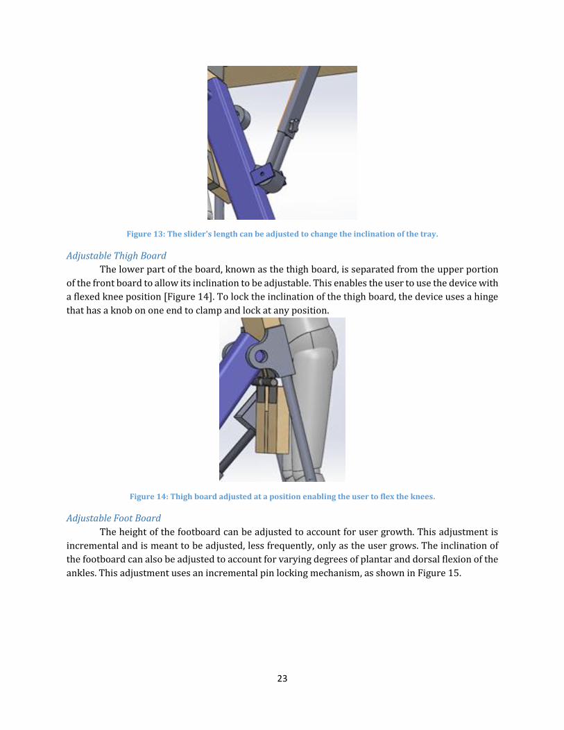
23
Figure 13: The slider's length can be adjusted to change the inclination of the tray.
Adjustable Thigh Board
The lower part of the board, known as the thigh board, is separated from the upper portion
of the front board to allow its inclination to be adjustable. This enables the user to use the device with
a flexed knee position [Figure 14]. To lock the inclination of the thigh board, the device uses a hinge
that has a knob on one end to clamp and lock at any position.
Figure 14: Thigh board adjusted at a position enabling the user to flex the knees.
Adjustable Foot Board
The height of the footboard can be adjusted to account for user growth. This adjustment is
incremental and is meant to be adjusted, less frequently, only as the user grows. The inclination of
the footboard can also be adjusted to account for varying degrees of plantar and dorsal flexion of the
ankles. This adjustment uses an incremental pin locking mechanism, as shown in Figure 15.

24
Figure 15: Footboard can pivot around an axis to enable ankle flexion.
6.2.2 Design 2
Design 2 was inspired from one of the client’s current devices. The client enjoys using her gait
walker so this design was created to offer a similar user experience. The design consisted of a harness
in which the user would be supported. An airspring would give the user a boost to ease weight on his
or her legs. The amount of air in the spring would be adjustable to change the amount lift force
provided as the user grows stronger. Since this design does not restrict the knees, the user is free to
flex his or her knees. A pivoting footboard would allow the user to flex his or her ankles as well.
Finally, this design would be growth adjustable by sliding the tray and airspring upwards [Figure 16].
Figure 16: Design 2.
Air Spring
The air spring shown in Figure 17 provides lift support to the user. The air spring is capable
of compensating any standing force that Felicity is unable to provide. The pressure of the air spring
can be adjusted with an onboard, battery powered, air compressor.
Tray Assembly
Air Spring
Scissor Jack
Frame
Harness

25
Figure 17: Air spring used for design 2.
Scissor Jack
The scissor jack shown in Figure 18 is incorporated in order to change the height of the air
spring based on Felicity’s growth.
Figure 18: Scissor Jack used in Design 2 to provide growth adjustability.
4.2.3 Design 3
Design 3 used the same concept as design 2 but used a counterweight system instead of an
airspring to provide the lifting force to the user [Figure 19].
Figure 19: Design 3.
Tray Assembly
Frame
Support Lever
Office Chair Lift
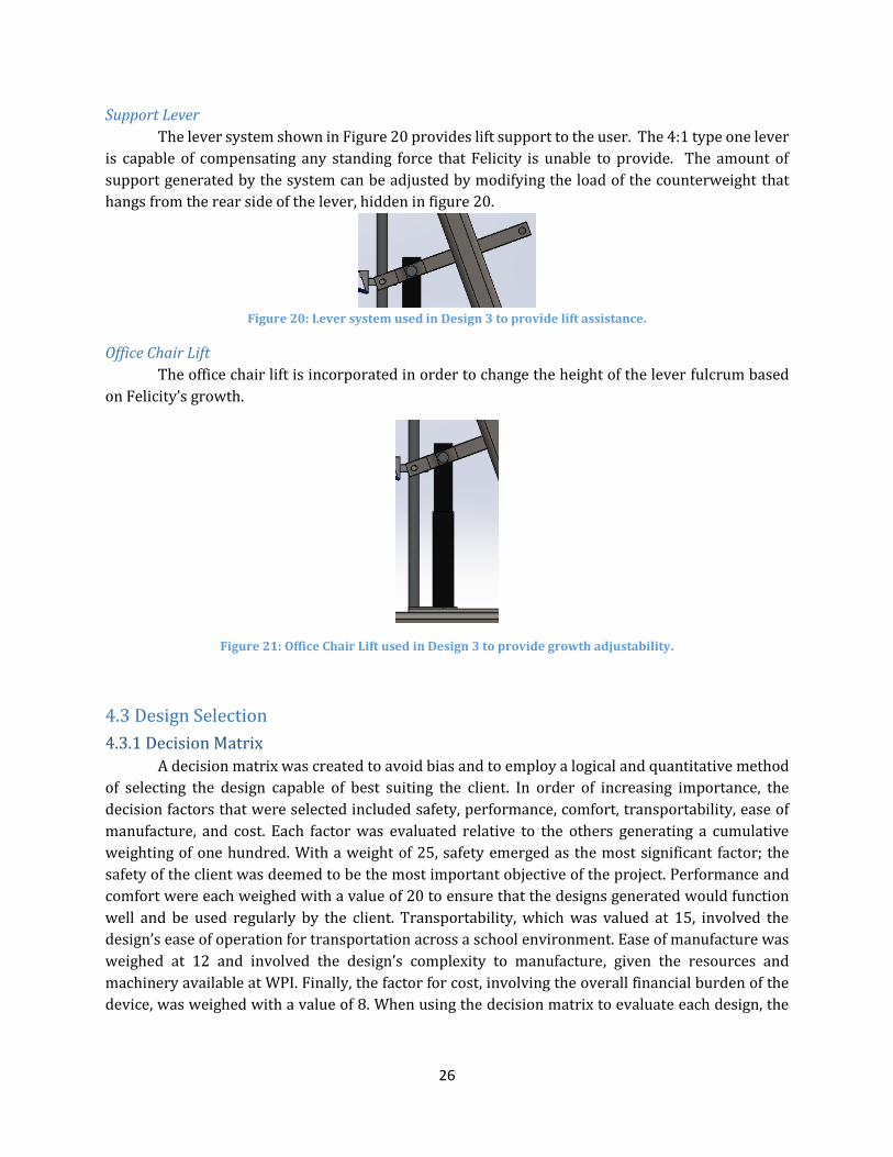
26
Support Lever
The lever system shown in Figure 20 provides lift support to the user. The 4:1 type one lever
is capable of compensating any standing force that Felicity is unable to provide. The amount of
support generated by the system can be adjusted by modifying the load of the counterweight that
hangs from the rear side of the lever, hidden in figure 20.
Figure 20: Lever system used in Design 3 to provide lift assistance.
Office Chair Lift
The office chair lift is incorporated in order to change the height of the lever fulcrum based
on Felicity’s growth.
Figure 21: Office Chair Lift used in Design 3 to provide growth adjustability.
4.3 Design Selection
4.3.1 Decision Matrix
A decision matrix was created to avoid bias and to employ a logical and quantitative method
of selecting the design capable of best suiting the client. In order of increasing importance, the
decision factors that were selected included safety, performance, comfort, transportability, ease of
manufacture, and cost. Each factor was evaluated relative to the others generating a cumulative
weighting of one hundred. With a weight of 25, safety emerged as the most significant factor; the
safety of the client was deemed to be the most important objective of the project. Performance and
comfort were each weighed with a value of 20 to ensure that the designs generated would function
well and be used regularly by the client. Transportability, which was valued at 15, involved the
design’s ease of operation for transportation across a school environment. Ease of manufacture was
weighed at 12 and involved the design’s complexity to manufacture, given the resources and
machinery available at WPI. Finally, the factor for cost, involving the overall financial burden of the
device, was weighed with a value of 8. When using the decision matrix to evaluate each design, the
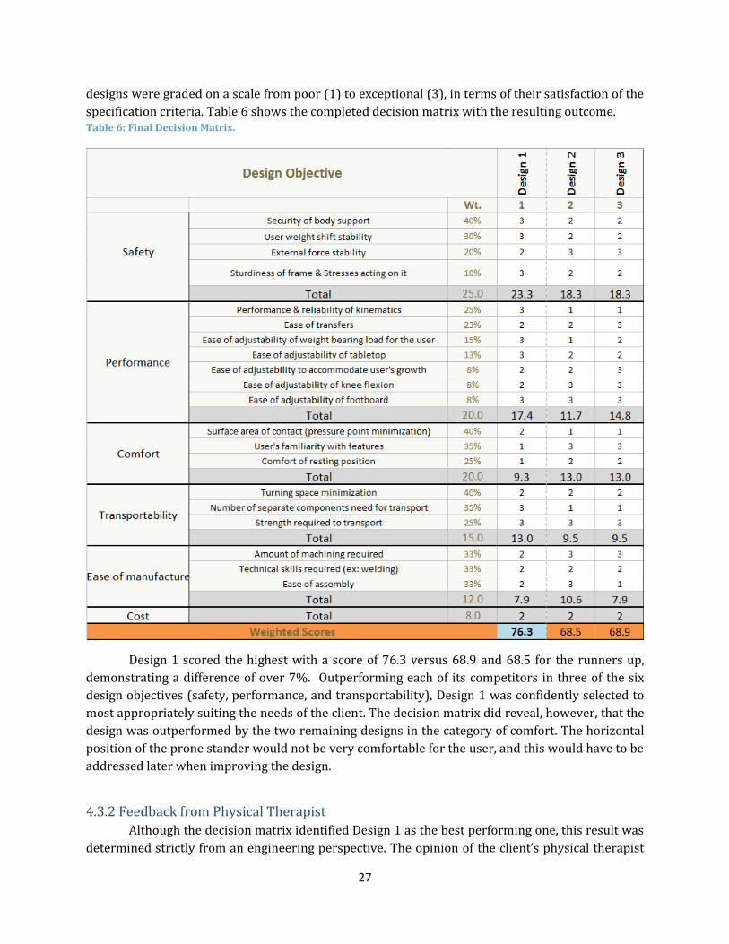
27
designs were graded on a scale from poor (1) to exceptional (3), in terms of their satisfaction of the
specification criteria. Table 6 shows the completed decision matrix with the resulting outcome. Table 6: Final Decision Matrix.
Design 1 scored the highest with a score of 76.3 versus 68.9 and 68.5 for the runners up,
demonstrating a difference of over 7%. Outperforming each of its competitors in three of the six
design objectives (safety, performance, and transportability), Design 1 was confidently selected to
most appropriately suiting the needs of the client. The decision matrix did reveal, however, that the
design was outperformed by the two remaining designs in the category of comfort. The horizontal
position of the prone stander would not be very comfortable for the user, and this would have to be
addressed later when improving the design.
4.3.2 Feedback from Physical Therapist
Although the decision matrix identified Design 1 as the best performing one, this result was
determined strictly from an engineering perspective. The opinion of the client’s physical therapist

28
would be valuable because of her expertise with rehabilitation devices. Therefore, the three designs
performing highest in the decision matrix evaluation were presented to her for observations.
Without disclosing the results of the engineering evaluation previously conducted, the physical
therapist was afforded the opportunity to provide her unbiased opinions of the three designs. The
objective was see if the client’s therapist would also choose Design 1, confirming the reliability of the
design selection process.
Feedback for Design 1:
Mrs. Goodhile was very impressed with the method of support illustrated by this design,
noting the level of familiarity Felicity would have with a prone stander. She also stated her preference
of the adjustable angle of inclination for which Design 1 would allow. Similar to devices previously
used by Felicity, she felt that this design would provide a strong level of familiarity while supporting
the client in a much more accommodating manner. She mentioned the stiff kneeboards in other
devices that rendered them unusable by Felicity due to her inability to achieve full lower-leg
extension.
Feedback for Design 2:
The physical therapist seemed to like this design, stating how impressed she was with the
two-tiered system allowing both height adjustments and vertical freedom. She noted, however, that
she did not feel the design would be best to suit the specific needs of Felicity. Mrs. Goodhile explained
that she felt the frame of Design 2 might serve as a distraction to both Felicity and her classmates,
therefore serving as more of a hindrance than an assistive device.
Feedback for Design 3:
Similar to the concerns expressed regarding Design 2, the therapist commented that the
frame may create too much of a distraction to other students, even if Felicity were to be placed in the
rear of the classroom. Although the design also simulated an enlarged version of a standard student
desk, she felt that the frame of Design 1 more closely mirrored that of a traditional standing device.
Although impressed with all three designs, the client’s physical therapist ultimately selected
Design 1 as that which would best cater to the needs of Felicity. This selection was made impartially,
prior to being informed of any other evaluative methods, fortifying the confidence in the selection of
Design 1 for the foundation of the project. With the design selection process complete, the next phase
was to finalize the design.

29
Chapter 7: Final Design
7.1 Iterations and Changes made to Design A variety of adjustments were made to the selected design following the conduction of
different analyses; these included both mathematical evaluations, such as static and stress analyses,
and observatory assessments using the client. Figure 22 shows the CAD model of the final design. The
most significant changes addressed the function of the device. The majority of changes, however,
affected the device’s overall dimensions, which improved manufacturability and load distribution on
the cirtical joints/structures of the device.
Figure 22: Final Design.
Tray Connector
Frame Assembly
Screw Rod
Board Assembly

30
7.1.1 Replacement of thigh board with knee board
The thigh board was merged with the main front board and a knee board was introduced, as
shown in Figure 23. This change was made after seeing Felicity in a prone stander and noticing that
she needed the kneeboard to support her weight.
Figure 23: The kneeboard supports the lower half of the user’s legs.
7.1.2 Placement of the screw rod
Figure 24 shows how the screw rod was moved to the middle plane of the device to distribute
the loads evenly across the device. This makes the device more stable and reduces potential tipping
hazards. The connection point of the screw rod on the front board was also moved closer to the base,
in order to increase the moment arm about the main beam of the device.
Figure 24: The screw rod is now placed in the middle of the device.
Kneeboard
Screw Rod
Main Beam

31
7.2 Final Design Decomposition
7.2.1 Frame Assembly
Figure 25 shows the Frame Assembly, which is the core structure that holds the board and
tray assemblies. It is composed of two main components, the base frame and the central beam.
Figure 25: Isometric view of Frame Assembly.
Base Frame
Figure 26 shows the base frame which is built out of 2in x 2in tubing with a thickness of ¼”.
Purchased T-brackets are used to attach the two short tubes to the two long tubes on the side. Four
casters (all with brakes) are bolted to the ends of the long tubes.
Figure 26: Base frame made of square tubing.
Central Beam
Base Frame

32
Central Beam
The central beam of the device is made out of a 3in x 3xin steel tube [Figure 27]. One end of
this tube is cut at a 20-degree angle. This end is welded to a .190in thick alloy steel plate, providing
the 70-degree angle of the support member. The plate is then bolted to the frame at each of its corner.
The brackets and pins on the central beam are for connecting the other sub-assemblies of the device
(the front board and the tray connector).
Figure 27: Side view of Central Beam.
7.2.2 Board Assembly
Figure 28 shows the board sub-assembly, which supports Felicity in a prone position from
her feet to her upper torso. The front board supports her from her thighs to her chest. Her knees are
supposed to fall in the gap underneath the front board and rest within the gap between the kneeboard
and front board. The third main component of the assembly is the footboard, on which the feet of the
user are to be strapped.

33
Figure 28: (a) Front and (b) rear views of front board.
Front, Knee and Foot boards
These components are made out of particle board with a thickness of .75 in. The panels are
cut using a circular saw. Counter boreholes are drilled for the bolts to go through and conceal the
heads of the bolts, preventing any discomfort for the user resting on top of the board.
Front board/knee board connection
Figure 29 shows the mechanism used to connect the front board and the kneeboard. Two
hinges are mounted on steel plates, which are bolted to each of the boards. The material for these
plates comes from the frame (.190in thick Alloy Steel). The plates give the space necessary for the
user’s knees. The hinges are lockable so that the kneeboard can be adjusted to any angular position
between -35° and +180°, where 0° is the condition in which the two plates are coplanar.
Front Board
Knee Board
Foot Board
Front board –
Knee Board
Connection
Tube for Screw
Rod Connection
Connection to
Central Beam
Tube for Foot Board
Connection
Angle adjustment
of Foot Board a b

34
Figure 28: Lockable hinges and steel plates are used to connect the front and kneeboards.
Tube for screw rod connection
The steel tube (1in outer diameter) shown in Figure 30 is attached to the front board with a
special aluminum clamp that was purchased. A pin, absent from the figure 29, connects this tube to
the screw rod at the lower end of the tube.
Figure 29: Tube connecting the screw rod to the front board.
Connection to central beam
Figure 31 shows two bearings (for ½” shaft) that are bolted to the bottom of the front board
to connect the assembly with the frame. The bearings rotate around a ½” diameter pin on the central
beam. There is a spacer in between the bearings and the board to prevent the bearings from colliding
with the central beam as the front board pivots.
Lockable
Hinge
Steel Plate
Location for Pin

35
Figure 30: Bearings are used to connect to a pin on the central beam to allow the Front Board to pivot.
Telescoping tubes for foot board connection
The footboard is attached to the kneeboard with two sets of telescoping tubes [Figure 32].
The inner tubes have a 1in outer diameter and are made out of aluminum. They are attached to the
kneeboard with a metal clamp and a bolt for additional security. There is a spacer between the board
and the tube to provide space for the movement of the outer tube. The outer tubes are locked to the
inner tubes with a snap button, similar to those found in standard crutches. The outer tubes have
eight holes spaced 0.6in apart, allowing the telescoping tubes to be locked at variant positions. This
mechanism enables the footboard to be lowered and provides growth adjustability for the user.
Figure 31: Telescoping tubes connecting the footboard with the kneeboard.
Angle adjustment of foot board
To make the angle of the footboard adjustable, it is connected to a ½” diameter tube with two
bearings. This tube is press fit into the two sets of telescoping tubes that are attached to the
kneeboard. This way, the footboard is able to pivot around the tube beneath it. An arc made of
aluminum plate has nine holes to lock the board at different angular positions using a removable pin
that goes through the outer tube and the arc. Figure 33 shows a picture of the entire mechanism.
Inner
tube
Outer tube
Holes for snap
button

36
Figure 32: Mechanism used to adjust and lock footboard at different angles.
7.2.3 Other components
Screw Rod
The screw rod assembly consists of the following components:
1) ½-10 ACME ROD
2) ½-10 ACME Cylindrical Nut
3) Metal tube
4) Huco Right Angle Gearbox (1:1 Ratio)
5) Crank
The cylindrical nut is press fit inside the metal tube, which is pinned to the plate of the base
assembly on its bottom end. The gearbox is connected to the rod by press fitting one of its shafts in
the side face of the ACME rod. The gearbox is mounted on an aluminum housing, which is pinned to
the pipe of the mounting pipe of the front board. Finally, a crank is connected to the remaining shaft
of the gearbox to enable the operator to conveniently drive the ACME rod.
Figure 33: Screw Rod Mechanism.
Arc with
incremental
holes
Hole for pin to lock
angular position

37
Tray
The tray is made out of the same particleboard as the other wood components of the device.
It is attached to the board assembly with hinges. The tray connector is pinned underneath on the
opposite side [Figures 35 and 36].
Figure 34: Isometric view of tray.
Tray Connector
The tray connector consists of a set of telescoping tubes that can be adjusted and locked by
operating a quick-release clamp like the one found under bicycle seats [Figure 36].
Figure 35: Side-view of tray connector.
7.3 Detailed Analysis To choose the proper dimensions and materials for the components of the device, a statics
analysis was performed followed by a stress analysis. Accompanied by manual calculations,
SolidWorks analyses were used to find the dimensions and material properties that would results in
the best compromise between performance and cost.
7.3.1 Statics Analysis
Free Body Diagrams
The objective of the static analysis was to determine the forces acting on the points shown in
Figure 37. To create a solvable set of equations, the analysis was separated into seven sections: the
Tray, Front Board, Center Beam, Screw Rod, Front Middle Beam, Back Middle Beam, and the Side

38
Beams. The free body diagrams and sets of equations for each of these sections can be found in
Appendix B. Several assumptions were made to make the analysis feasible. These assumptions were
intended to model the maximum anticipated loads, in order to calculate correct safety factors.
Figure 36: Joints (Letters on Diagram) whose forces were identified after statics analysis.
Assumptions:
1. Weight of user is 60 lbs., anticipating Felicity’s growth
2. Felicity’s body weight is separated as follows; 10% arms, 70% torso/head/thighs,
30% lower legs/feet
3. Front board force calculations includes the weight of Felicity’s arms, therefore the
front board supports full body load (i.e. there is no load on the tray)
4. Table top is horizontal (changes in table angle are negligible)
5. Knee-board angle is 20 degrees relative to the front board for comparative purposes
however horizontal and parallel positions were checked
6. Locations of user’s center of gravity were based on anthropometric tables and
measurements taken of Felicity (CDC 2000).

39
Calculated Values
A Mathcad file was created to solve the system of equations for each component of the device
(See Appendix C). The results revealed three critical components of the device requiring considerable
attention to ensure the safe performance of the device. The first of these forces was the one acting on
the screw rod (Point A). Because the screw rod acts as a link pinned at both ends, this force follows
the same direction as the screw rod. The second and third critical forces were the horizontal and
vertical forces acting on Point B, which is a pin joint. Finally, the last critical load was the moment at
point G caused by the front board sub-assembly, which would contain the user during use.
Table 7 shows the values of these critical loads for three different angles of inclination of the
front board relative to the ground. The force at Point A and the vertical force at Point B are greatest
while the device is in the vertical position. However, the moment at Point G is largest when the angle
of the device is 45 degrees, and the horizontal force on B is largest when the angle is 67.5 degrees.
Identifying the maximum values for each of the critical loads was essential to the stress analysis,
which was performed next.
Table 7: Values of critical loads at three different angles of inclination.
Angle of
Front Board
Force on
Point A
Vertical Force on
Point B
Horizontal Force on
Point B
Moment at point G
90ᴼ 54 lbs. 19 lbs. 32 lbs. 1082 lbs.*in
67.5ᴼ 26 lbs. 13 lbs. 61 lbs. 1223 lbs.*in
45ᴼ 21 lbs. 10 lbs. 49 lbs. 1516 lbs.*in
7.3.2 Stress Analysis
Analysis of individual components
Material selection and component sizing were determined based on stress analyses at critical
points within the assembly. The critical sections and components can be found in Figures 38 and 39.
Prior to performing a component selection, the tensile/compressive forces and moments, to which
each critical part would be subject, were calculated based upon a state of maximized loading. These
values were obtained through similar Free-Body Diagram processes that allowed for calculation of
the internal forces acting throughout the assembly (See Appendix D).
Standard parts components were then selected from industrial suppliers, and material data
was obtained for further analysis. Dependent upon the loads to which each part would be exposed, a
factor of safety analysis was conducted. The factor of safety values found for each component are
representative of the parts determined to be most cost effective, for their specified duty.

40
Knee-Hinge Connector (Bolts) Bolts at Joint Q Bolts at Front of Central Plate
Tensile Stress Tensile Stress Tensile Stress
Tensile Stress at Max Tensile
Force Max Stress at/between Max Loads Max Stress at/between Max Loads
σ = 1249 psi σ = 87.85 psi σ = 39.22 psi
UTS of Steel (σ) = 58000 psi UTS of Steel (σ) = 58000 psi UTS of Steel (σ) = 58000 psi
Factor of Safety = 46.4 Factor of Safety = 660.2 Factor of Safety = 1478.8
Shear Stress Shear Stress Shear Stress
Shear Stress at Max Shear Force Shear Stress at Max Shear Force Shear Stress at Max Shear Force
τ = 809.78 psi τ = 10.205 psi τ = 16.65 psi
UTS of Steel (σ) = 34800 psi UTS of Steel (σ) = 34800 psi UTS of Steel (σ) = 34800 psi
Factor of Safety = 43.0 Factor of Safety = 3410 Factor of Safety = 2090
Figure 37: Results of stress analysis of critical components of the design.
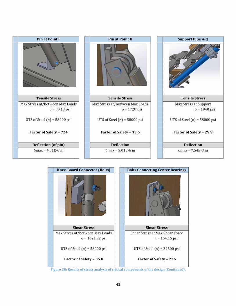
41
Pin at Point F Pin at Point B Support Pipe A-Q
Tensile Stress Tensile Stress Tensile Stress
Max Stress at/between Max Loads Max Stress at/between Max Loads Max Stress at Support
σ = 80.13 psi σ = 1728 psi σ = 1940 psi
UTS of Steel (σ) = 58000 psi UTS of Steel (σ) = 58000 psi UTS of Steel (σ) = 58000 psi
Factor of Safety = 724 Factor of Safety = 33.6 Factor of Safety = 29.9
Deflection (of pin) Deflection Deflection
δmax = 4.01E-6 in δmax = 3.01E-6 in δmax = 7.54E-3 in
Knee-Board Connector (Bolts) Bolts Connecting Center Bearings
Shear Stress Shear Stress
Max Stress at/between Max Loads Shear Stress at Max Shear Force
σ = 1621.32 psi τ = 154.15 psi
UTS of Steel (σ) = 58000 psi UTS of Steel (σ) = 34800 psi
Factor of Safety = 35.8 Factor of Safety = 226
Figure 38: Results of stress analysis of critical components of the design (Continued).

42
Chapter 8: Manufacturing Following the completion of the design and analysis of each component, the manufacturing
of the device was set to begin. A variety of components were purchased pre-assembled and the
remainder of the parts were manufactured and assembled from raw materials. The raw materials
were milled, drilled, and welded to manufacture a functioning device.
8.1 Frame Assembly The frame was constructed with both aluminum and steel square tubing. The frame was
assembled in two parts, the base and the central beam.
8.1.1 Base
The base was constructed using 2 inch square aluminum tubing with a wall thickness of 0.25
inches. A 12 foot tube of aluminum was cut into four parts using a band saw: two 35 inch side
members and two 25 inch cross members. Each side member was drilled with two holes to attach
casters. Each cross member was drilled using the drill press with two holes, used to attach the center
beam subassembly described in Section 7.1.2. The side members and cross members were then laid
out to drill the appropriately placed holes for T-brackets. These T-brackets were placed on the top
and bottom of the base assembly to securely fasten the side members and cross members together
(Figure 40).
Figure 39: T-Bracket Assembly.
8.1.2 Central Beam
The central beam of the device was constructed of two main components; a 9in x 13in steel
base plate and a 3in square steel tube cut to a length of 28 inches. The central beam was designed to
support the upper portion of the device at an at an angle of approximately 70 degrees with respect
to the horizontal, allowing an additional support member (support pipe A-Q) to be concealed within
the space created within the angle created by the weld [Figure 41]. In order to ensure the strength of
the connection between the steel square tube and the steel plate, which were anticipated to sit at an
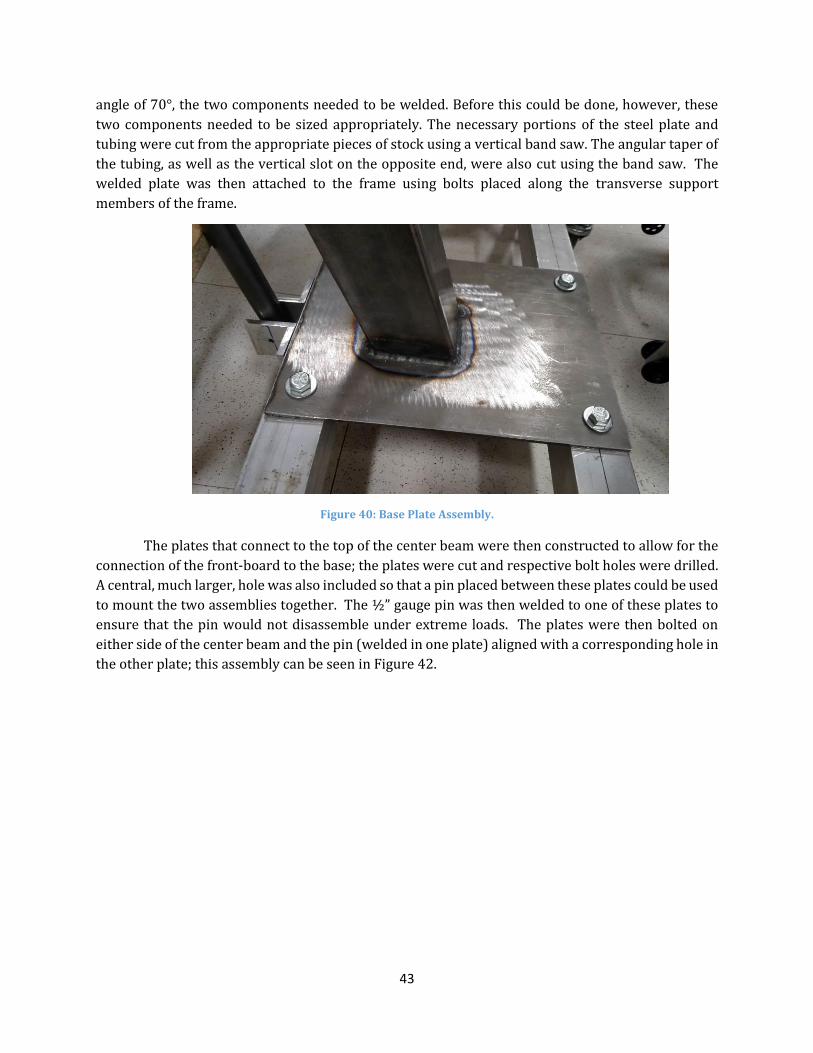
43
angle of 70°, the two components needed to be welded. Before this could be done, however, these
two components needed to be sized appropriately. The necessary portions of the steel plate and
tubing were cut from the appropriate pieces of stock using a vertical band saw. The angular taper of
the tubing, as well as the vertical slot on the opposite end, were also cut using the band saw. The
welded plate was then attached to the frame using bolts placed along the transverse support
members of the frame.
Figure 40: Base Plate Assembly.
The plates that connect to the top of the center beam were then constructed to allow for the
connection of the front-board to the base; the plates were cut and respective bolt holes were drilled.
A central, much larger, hole was also included so that a pin placed between these plates could be used
to mount the two assemblies together. The ½” gauge pin was then welded to one of these plates to
ensure that the pin would not disassemble under extreme loads. The plates were then bolted on
either side of the center beam and the pin (welded in one plate) aligned with a corresponding hole in
the other plate; this assembly can be seen in Figure 42.

44
Figure 41: Center Beam Pivoting Connection.
8.2 Front Board Assembly
8.2.1 Assembly of Boards
The wood material used for the board assembly was ¾” particleboard due to its availability
and material strength. The four wood components (tray, torso board, knee board, and foot board)
were cut using a band saw from a 4 x 6 foot stock of particleboard. The components were cut to the
designed dimensions and were then drilled with counter-bore holes using a drill press. Counter-bore
holes were used to prevent bolt heads from sticking out of the boards and causing potential harm to
the user [Figure 43].
Figure 42: Sample of counter-bore Holes constructed within the front board.
The boards that support the torso and knees were manufactured first. Once the boards were
cut and drilled, the metal plates for the hinges were then bolted to the board [Figure 44].
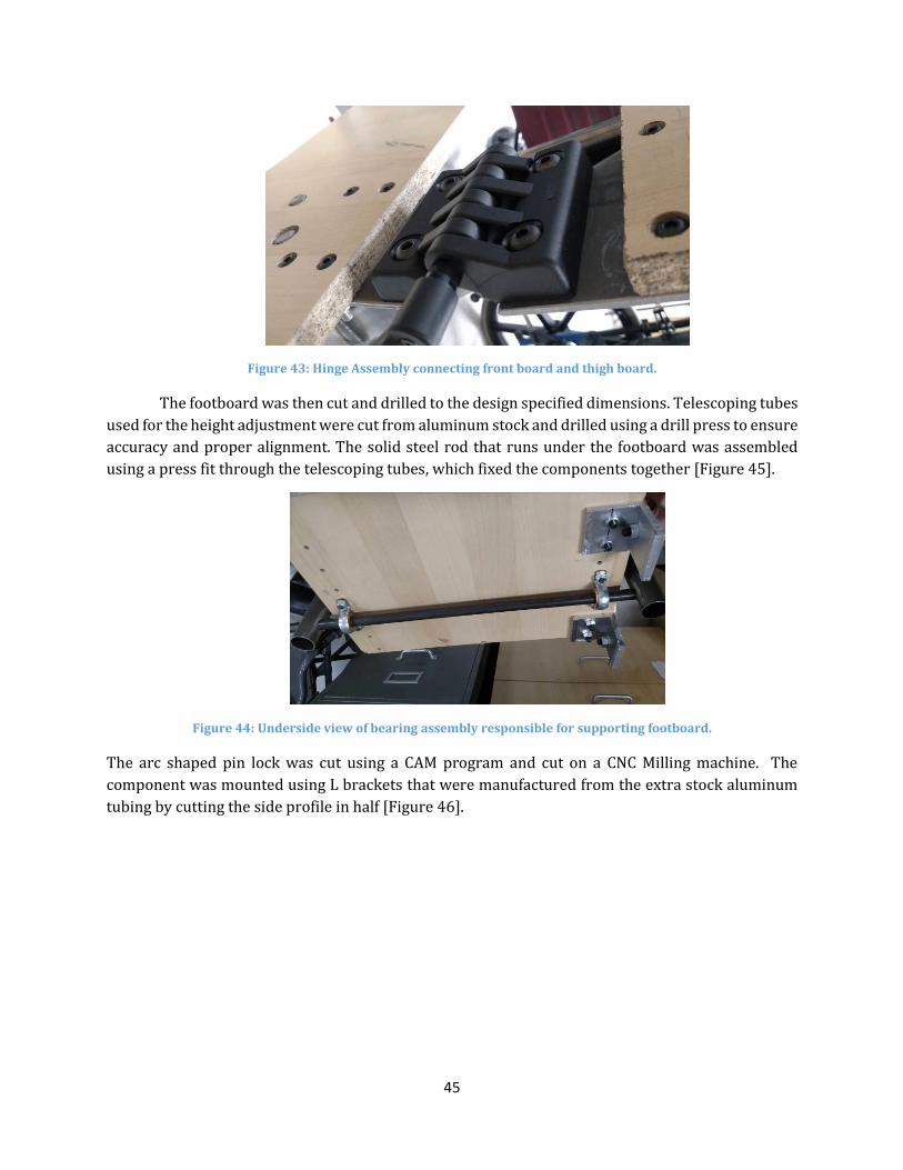
45
Figure 43: Hinge Assembly connecting front board and thigh board.
The footboard was then cut and drilled to the design specified dimensions. Telescoping tubes
used for the height adjustment were cut from aluminum stock and drilled using a drill press to ensure
accuracy and proper alignment. The solid steel rod that runs under the footboard was assembled
using a press fit through the telescoping tubes, which fixed the components together [Figure 45].
Figure 44: Underside view of bearing assembly responsible for supporting footboard.
The arc shaped pin lock was cut using a CAM program and cut on a CNC Milling machine. The
component was mounted using L brackets that were manufactured from the extra stock aluminum
tubing by cutting the side profile in half [Figure 46].

46
Figure 45: Arch-Shaped Pin Locking Mechanism.
8.2.2 Padding
Both the front board and kneeboard were covered with padding cut from exercise mats. The
mats were chosen due to the ability to resist water absorption and due to the thick cushion material.
The mats were cut down to size and glued to the boards using gorilla glue.
8.2.3 Straps
Straps were added to the device to act as another method of support. The straps were
attached to the device through slots cut into the wood boards. Four holes were drilled in the front
board, each at the starting location for the intended slots. The slots were cut using a handheld power
jigsaw, starting at the pre-drilled locations.
8.2.4 Lateral Supports
Adjustable lateral supports were added to the top portion of the front board, intended to
secure the upper body of a user in a central position. Manufactured using leftover particleboard and
padding, there are a total of six support blocks. Attached to one another with Velcro, the blocks can
be added or removed as the width of the user dictates. The supports are shown in Figure 46.
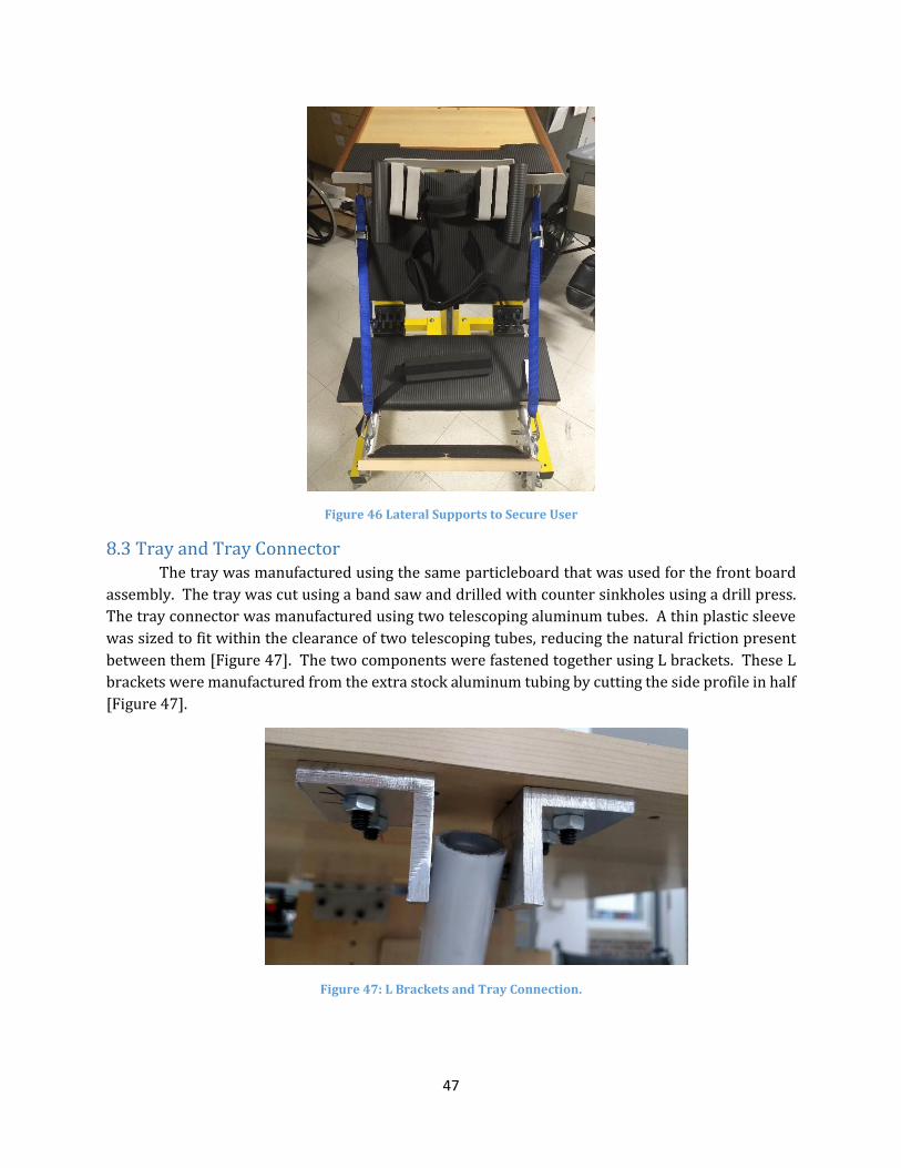
47
Figure 46 Lateral Supports to Secure User
8.3 Tray and Tray Connector The tray was manufactured using the same particleboard that was used for the front board
assembly. The tray was cut using a band saw and drilled with counter sinkholes using a drill press.
The tray connector was manufactured using two telescoping aluminum tubes. A thin plastic sleeve
was sized to fit within the clearance of two telescoping tubes, reducing the natural friction present
between them [Figure 47]. The two components were fastened together using L brackets. These L
brackets were manufactured from the extra stock aluminum tubing by cutting the side profile in half
[Figure 47].
Figure 47: L Brackets and Tray Connection.

48
8.4 Front Board Angle Adjuster/Support
8.4.1 Telescoping Tube Mechanism
The telescoping tube mechanism attached to the front board was manufactured similarly to
that of the tray connector, however the main difference is the tube length. Each tube was cut to a
length of 12 inches using a band saw. The other main difference is the presence of six additional
holes on the outer tube and one extra hole in the inner tube. These holes allow for the incremental
insertion of a ¼” to further ensure the safety of the locking mechanism. The telescoping mechanism
was then assembled to the base plate and front board using similar L brackets as previously used
throughout the device.
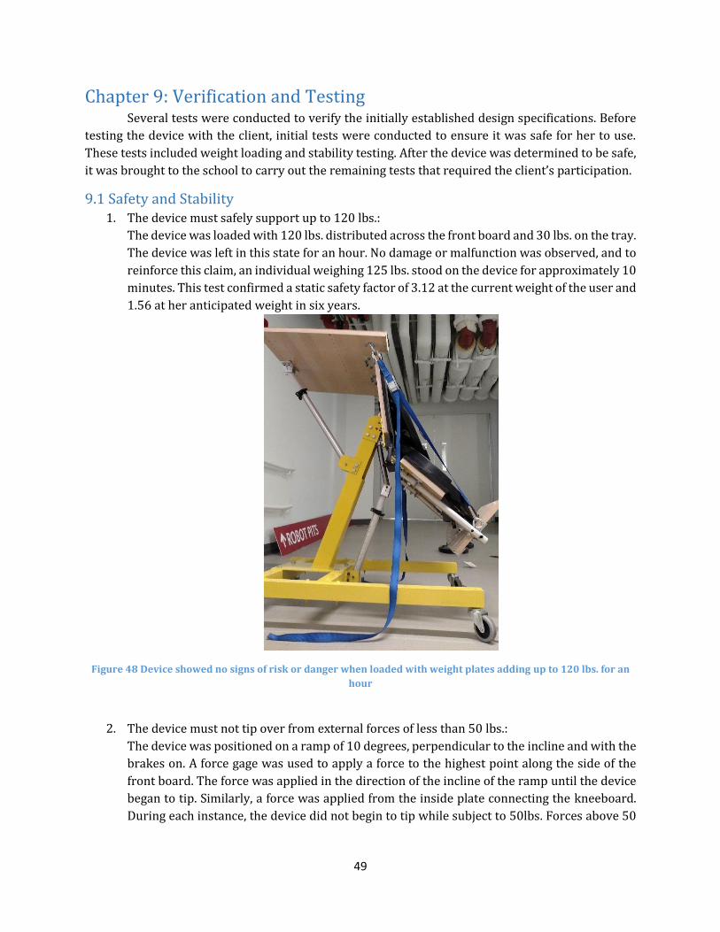
49
Chapter 9: Verification and Testing Several tests were conducted to verify the initially established design specifications. Before
testing the device with the client, initial tests were conducted to ensure it was safe for her to use.
These tests included weight loading and stability testing. After the device was determined to be safe,
it was brought to the school to carry out the remaining tests that required the client’s participation.
9.1 Safety and Stability 1. The device must safely support up to 120 lbs.:
The device was loaded with 120 lbs. distributed across the front board and 30 lbs. on the tray.
The device was left in this state for an hour. No damage or malfunction was observed, and to
reinforce this claim, an individual weighing 125 lbs. stood on the device for approximately 10
minutes. This test confirmed a static safety factor of 3.12 at the current weight of the user and
1.56 at her anticipated weight in six years.
Figure 48 Device showed no signs of risk or danger when loaded with weight plates adding up to 120 lbs. for an
hour
2. The device must not tip over from external forces of less than 50 lbs.:
The device was positioned on a ramp of 10 degrees, perpendicular to the incline and with the
brakes on. A force gage was used to apply a force to the highest point along the side of the
front board. The force was applied in the direction of the incline of the ramp until the device
began to tip. Similarly, a force was applied from the inside plate connecting the kneeboard.
During each instance, the device did not begin to tip while subject to 50lbs. Forces above 50
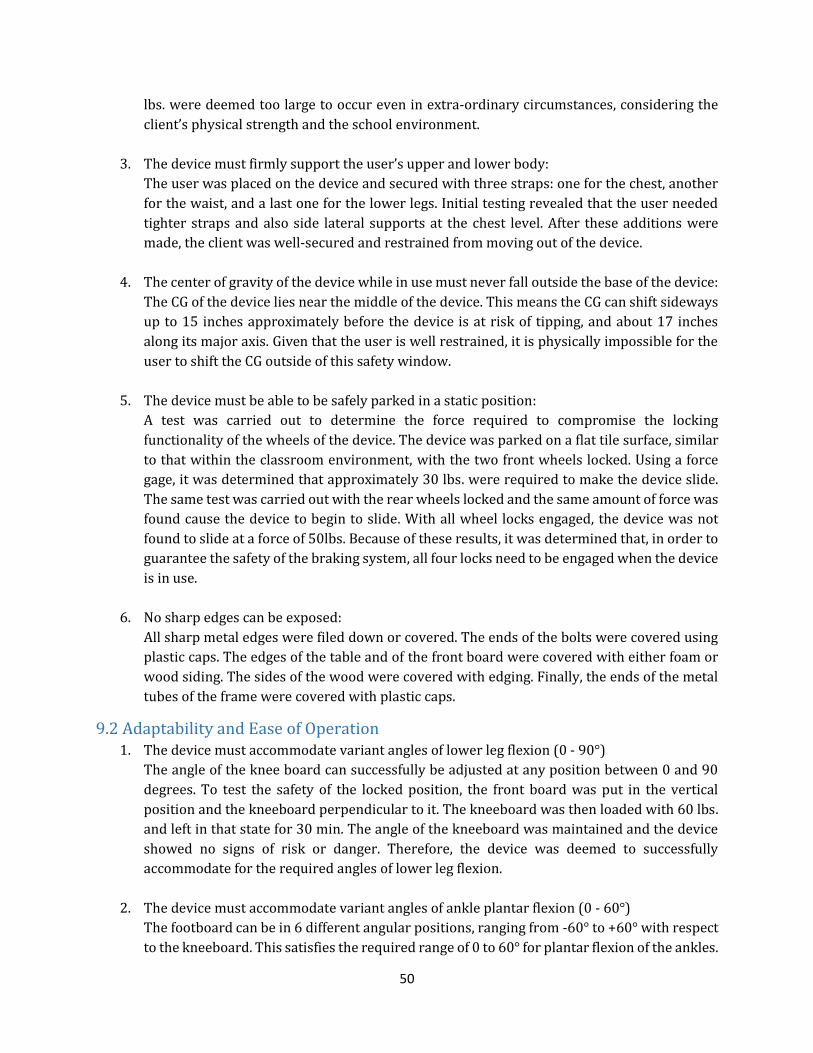
50
lbs. were deemed too large to occur even in extra-ordinary circumstances, considering the
client’s physical strength and the school environment.
3. The device must firmly support the user’s upper and lower body:
The user was placed on the device and secured with three straps: one for the chest, another
for the waist, and a last one for the lower legs. Initial testing revealed that the user needed
tighter straps and also side lateral supports at the chest level. After these additions were
made, the client was well-secured and restrained from moving out of the device.
4. The center of gravity of the device while in use must never fall outside the base of the device:
The CG of the device lies near the middle of the device. This means the CG can shift sideways
up to 15 inches approximately before the device is at risk of tipping, and about 17 inches
along its major axis. Given that the user is well restrained, it is physically impossible for the
user to shift the CG outside of this safety window.
5. The device must be able to be safely parked in a static position:
A test was carried out to determine the force required to compromise the locking
functionality of the wheels of the device. The device was parked on a flat tile surface, similar
to that within the classroom environment, with the two front wheels locked. Using a force
gage, it was determined that approximately 30 lbs. were required to make the device slide.
The same test was carried out with the rear wheels locked and the same amount of force was
found cause the device to begin to slide. With all wheel locks engaged, the device was not
found to slide at a force of 50lbs. Because of these results, it was determined that, in order to
guarantee the safety of the braking system, all four locks need to be engaged when the device
is in use.
6. No sharp edges can be exposed:
All sharp metal edges were filed down or covered. The ends of the bolts were covered using
plastic caps. The edges of the table and of the front board were covered with either foam or
wood siding. The sides of the wood were covered with edging. Finally, the ends of the metal
tubes of the frame were covered with plastic caps.
9.2 Adaptability and Ease of Operation 1. The device must accommodate variant angles of lower leg flexion (0 - 90°)
The angle of the knee board can successfully be adjusted at any position between 0 and 90
degrees. To test the safety of the locked position, the front board was put in the vertical
position and the kneeboard perpendicular to it. The kneeboard was then loaded with 60 lbs.
and left in that state for 30 min. The angle of the kneeboard was maintained and the device
showed no signs of risk or danger. Therefore, the device was deemed to successfully
accommodate for the required angles of lower leg flexion.
2. The device must accommodate variant angles of ankle plantar flexion (0 - 60°)
The footboard can be in 6 different angular positions, ranging from -60° to +60° with respect
to the kneeboard. This satisfies the required range of 0 to 60° for plantar flexion of the ankles.
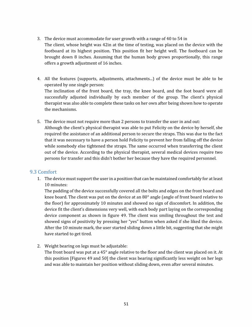
51
3. The device must accommodate for user growth with a range of 40 to 54 in
The client, whose height was 42in at the time of testing, was placed on the device with the
footboard at its highest position. This position fit her height well. The footboard can be
brought down 8 inches. Assuming that the human body grows proportionally, this range
offers a growth adjustment of 16 inches.
4. All the features (supports, adjustments, attachments...) of the device must be able to be
operated by one single person:
The inclination of the front board, the tray, the knee board, and the foot board were all
successfully adjusted individually by each member of the group. The client’s physical
therapist was also able to complete these tasks on her own after being shown how to operate
the mechanisms.
5. The device must not require more than 2 persons to transfer the user in and out:
Although the client’s physical therapist was able to put Felicity on the device by herself, she
required the assistance of an additional person to secure the straps. This was due to the fact
that it was necessary to have a person hold Felicity to prevent her from falling off the device
while somebody else tightened the straps. The same occurred when transferring the client
out of the device. According to the physical therapist, several medical devices require two
persons for transfer and this didn’t bother her because they have the required personnel.
9.3 Comfort 1. The device must support the user in a position that can be maintained comfortably for at least
10 minutes:
The padding of the device successfully covered all the bolts and edges on the front board and
knee board. The client was put on the device at an 80° angle (angle of front board relative to
the floor) for approximately 10 minutes and showed no sign of discomfort. In addition, the
device fit the client’s dimensions very well, with each body part laying on the corresponding
device component as shown in figure 49. The client was smiling throughout the test and
showed signs of positivity by pressing her “yes” button when asked if she liked the device.
After the 10 minute mark, the user started sliding down a little bit, suggesting that she might
have started to get tired.
2. Weight bearing on legs must be adjustable:
The front board was put at a 45° angle relative to the floor and the client was placed on it. At
this position [Figures 49 and 50] the client was bearing significantly less weight on her legs
and was able to maintain her position without sliding down, even after several minutes.
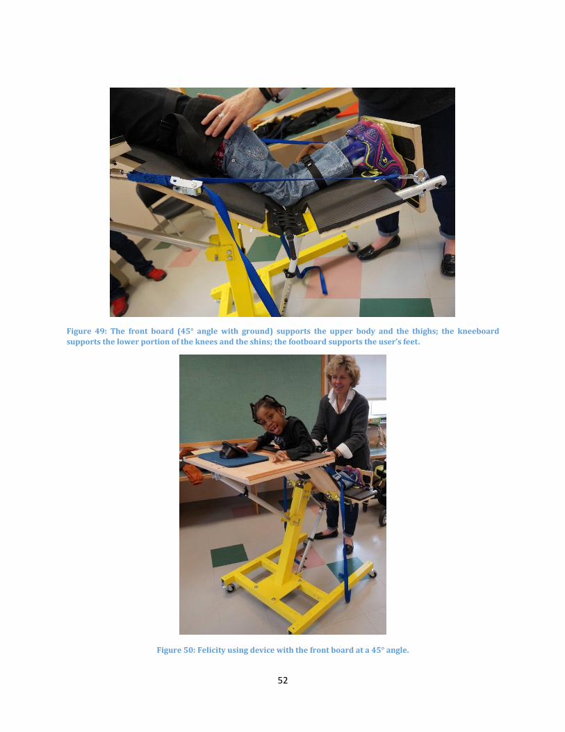
52
Figure 49: The front board (45° angle with ground) supports the upper body and the thighs; the kneeboard
supports the lower portion of the knees and the shins; the footboard supports the user’s feet.
Figure 50: Felicity using device with the front board at a 45° angle.
53
9.4 Transportability 1. The width of the device must be less than 30in:
The device is 29in at its widest point.
2. The length of the device must be less than 50in:
The device is 36in at its longest point.
3. The height of the device must be less than 78in:
The maximum height of the device is 44in.
4. The turning diameter of the device must not exceed 60in:
The device has four swivel casters giving the device a turning radius of 23 in (the diagonal
measurement of the device is 46in).
5. The device must be easily transportable throughout the Roosevelt School:
The device was transported from the entrance of the school to the physical therapy room,
where it will be used most often. The device was easily transported through several doors
and through an elevator. In addition, the device also traversed an ADA compliant ramp at
Worcester Polytechnic Institute.
9.5 Miscellaneous 6. The device must include or allow for the use of a flat surface to enable the user to participate
in engaging activities:
The device includes a large tray of dimensions 15in by 20in. When on the device, Felicity was
able to place both her arms comfortably on the tray. The table was large enough to fit the
client’s Velcro tray on which she places several of her toys. While on the device, Felicity
played with her “Yes” and “No buttons. The table has lips on the edges that prevented Felicity
from pushing her toys off the table.
7. The device must minimize the amount of maintenance it needs throughout its life cycle:
The device only uses simple fasteners such as bolts. All the bolts were tightened and those
undergoing the biggest loads were secured with a lock nut to prevent them from loosening
over time. The device does not require any regular maintenance other than occasional
cleaning as it is deemed necessary.

54
Chapter 10: Results and Discussion The proper analysis of the device required the cumulative efforts of a variety of isolated, as
well as user-incorporated, testing protocols. Following the completion and preliminary refinement
of the standing device, the previously mentioned evaluative methods were utilized to ascertain the
effectiveness with which the prototype was able to successfully improve the situation of the client.
10.1 Functionality Testing In order to successfully fulfill the anticipated requirements, specifically with regard to the
level of adjustability in the amount of support offered by the device, an array of specifications was
established. Each adjustable component was assigned a desired angular range of operation. In
addition, a preferred range of support was also generated for each component, based upon the
anticipated growth of the client.
10.1.1 Effective Range of Motion
As previously mentioned, a complication regarding the gradual angular adjustment of the
device, presented itself as construction neared completion; the strength of the gearbox, necessary to
allow for this feature, could not be guaranteed, and it needed to be removed from the design. In its
place, a system of telescoping tubes, affording intermittent angular adjustments, was included within
the design.
Although slightly obtrusive to the anticipated success of the device, the corrective measures
did not detract from the effective range of motion provided by the device. The desired range of
support, ideal to the muscular abilities of the client, was still achieved, although the angle of
inclination was ultimately unable to be adjusted with a user in the device.
10.1.2 Support of Loading
In order to properly satisfy load requirements, several iterations were required once initial
assembly had begun. The hinges connecting the kneeboard to the front board were identified to be
responsible for sustaining a majority of the weight exerted by the user, provided the manner in which
she was observed to support her bodyweight. The components selected, however, were incapable of
fulfilling the necessary load requirements. Although this realization momentarily hampered the
construction process, additional methods of support were designed to compensate for the weakness
displayed by these components.
The system of straps included to assist the problematic hinges fit seamlessly among the
remainder of the remaining parts. Their inclusion exceeded the anticipated load capabilities of the
device substantially, promoting a much wider range of loads capable of being supported.
10.2 Integration within User Environment The ability of the device to fit seamlessly within the daily routines of both the caregiver and
the student user was paramount to the success of the standing device. Success in this aspect would
ensure the continued use of this device, promoting the assistive effects that it has been designed to
encompass.
55
10.2.1 Classroom and Caregiver Interaction
The design of the device was completed in a fashion that paid attention to the limitations of
the specific classroom within which it was to be utilized. The design also considered the physical
requirements to be exhibited by a caregiver attempting to place the client within the device. Just as
important as the safety of the client, the safety of the caregiver was also judiciously taken into
account. While observed utilizing the final product, the physical therapist expressed gratitude for the
ease of adjustability and for the level of personalization included within the design.
10.2.2 User Interaction
The interaction of the user with her device went exactly as envisioned, largely due to the
several intervals of revisions following the initial testing of the device. Each time the device was
subject to testing involving the client, additional areas of improvement, allowing for further catering
to the specific needs of the student, were observed and implemented. The final product was observed
to successfully satisfy each of her needs, promoting a level of support unlike that promoted by any of
the other devices used previously.
10.3 Physical and Social Development Through the success of the device’s support functionality, the user has the ability to be
positioned in an upright position, satisfying the overall goal to facilitate physical and social
development. The use of this device will potentially lead to several health benefits including
improved bone integrity and skeletal development, improved circulation, and improved physical
strength. In addition, the height of the device will allow for the user to interact with peers at equal
eye level.

56
Chapter 11: Future Work Although the design currently meets each of the client needs and design objectives, there is
still ample room for further improvement. The device is composed of many components containing
holes, requiring precise alignment so that they may be properly fastened to one another. One example
of such subassembly is the telescoping tubes responsible for connecting the footboard to the
kneeboard. To accommodate user growth, the length of these tubes can be manipulated by
depressing a button and locking it within a different, collinear hole, much like the mechanism found
on standard crutches. The holes of these components were drilled using a manual drill press, which
may have compromised the linearity of these holes. To offset such error, the diameter of each hole
was increased slightly, avoiding any misalignment that might have otherwise been allowed to occur
during assembly. Unfortunately, the downside of such allowances is a reduction in the sturdiness of
the subassembly; the inclusion of slightly larger diametric tolerances to, ensure the linear alignment
of the two sets of telescoping tubes, allows subtle instability upon the redistribution of weight during
the loading of the footboard. Although the device is sufficiently steady for safe use, manufacturing by
means of CNC could ensure an enhanced level of precision, especially among the aforementioned
components. In addition, a more carefully tailored installation of subassemblies, expected to provide
adjustability, would also simplify any required force to carry out such adjustments.
Another opportunity for improvement would be the addition of features capable of
facilitating transfer. Currently, the device requires two persons to safely secure the client. Adding
supports to hold the user while a single caregiver secures the safety straps would simplify the process
greatly by removing the need for assistance provided by a second individual. This could be, for
instance, a seat, on which the client could be placed, while the caregiver performs the necessary
safety adjustments. This would also benefit the slightly under-staffed teaching community of the
Roosevelt School capable of providing care for a student requiring the use of the device.
A final area of improvement encompasses the material selection used during assembly of the
device. Using hardwood instead of composite board for the tray, front, and knee boards, for example,
would result in a more aesthetically pleasing and sturdier device; the particle board used provides
significantly weaker shear resistance and, consequently, does not support assembly techniques
utilizing threading. The aesthetics of the frame could also be improved by applying additional, but
thinner, layers of paint. Finally, using casters with larger lock pedals would simplify the process of
engaging these features for the caregivers.

57
Chapter 12: Conclusion The device safely and successfully meets the needs of the client and has been received with
great enthusiasm by her physical therapist. The device will enable the client to bear weight on her
legs, promoting the bone and muscle development that can be hampered in a seated position. The
device will, unlike those used previously by the client, also help to promote a gradual reduction in
the joint flexion exhibited in her lower extremities. The large tabletop provides ample room for her
to complete all of her typical classroom activities (Figure 51). Due to the size and manner in which
she is supported, the device allows the user to interact with her peers at eye level.
Figure 51: Client Performing Activities On Device.
Compared to the assistive standers previously used by the client, her new device more
properly accommodates the specific complexities of her condition. Because the device allows the
knee flexion that she displays, the client appears much more comfortably supported than when
observed in other devices. The overall cost of the device, which includes extraneous materials,
coupled with an anticipated profit margin and labor estimates, places the device comparable among
existing products in terms of consumer cost. Table 8 lists the material cost of the device in addition
to retail costs for various assistive standers.
Table 8: Cost of Project Device Compared to Retail Prices of Commercial Devices.
Device Price
Final Assisted Standing Device $780
Rifton Prone Stander $1,790
TherAdapt Prone Stander $1,010
Prospect Designs Alicia Stander $1,454
In addition to meeting the functional specifications identified, the device was enthusiastically
accepted by both the user and her physical therapist. According to the physical therapist, the device
will be slowly incorporated within the exercises performed during their appointments together; once

58
the student develops a sufficient level of comfort while using the device, however, they plan to slowly
implement the device into the remainder of her school day. Use of the device in the absence of the
physical therapist will also require a trial period in the classroom, in which classroom aides will need
to develop a level of familiarity with the operation of the device. While the integration of the device
into the user’s school day will be gradual, her physical therapist expressed confidence in the ability
of the device to eventually lead to the anticipated physical and social benefits to the user.

59
Bibliography
Altimate Medical Inc (2003). Magician Owner's Manual, EasyStand: 28.
Bundonis, J. (2009). "Benefits of Early Mobility with an Emphasis on Gait Training."
Caulton, J. M. (2004). "A randomised controlled trial of standing programme on bone mineral density in non-ambulant children with cerebral palsy." Arch Dis Child 89: 5.
CDC (2000). 2 to 20 years: Girls Stature Weight-for-age percentiles.
Daigle, A. (1999). "Fact Sheet on Standing Aids." Retrieved September 15, 2014, from http://www.abledata.com/abledata_docs/standaid.htm.
Drugs.com (2014). from http://www.drugs.com/valium.html.
Gesell, A. (1938). "The tonic neck reflex in the human infant: Morphogenetic and clinical science." The Journal of Pediatrics 13(4): 9.
Neurol, J. C. (1996). Baclofen in the treatment of cerebral palsy.
Noble, E. (2014) Choosing Between Adaptive Standers.
Rifton (2014). "Rifton Pacer Gait Trainers." Features and Accessories. Retrieved September 28, 2014, from http://www.rifton.com/products/gait-trainers/pacer-gait-trainers.
Rifton (2014). Rifton Prone Stander.
Staff, H. (2012, September 20, 2012). "Orthopedic Surgery for Cerebral Palsy." from http://www.webmd.com/children/orthopedic-surgery-for-cerebral-palsy.
Warner, M. P. (2007). "Standing Tall: The Benefits of Standing Devices." Exceptional Parent 37(3): 2.
Zeiter, F. B. H. a. W. J. (1946). "Treatment of Cerebral Palsy."

60
Appendices Appendix A: Decision Matrix used on Preliminary Designs

61
Appendix B: Free Body Diagrams and Static Analysis of Final Design
FBD for Tray
Defined Variables: WFelicity = Weight of Felicity WA = Weight of
arms (10% of body weight)
WT = Weight of tray DϴTC = Load caused by
tray connection
Knowns: WA, WT
Unknowns: CY, Cx, DϴTC
Equations:
1.
2. 3.

62
FBD for Board Assembly
Defined Variables: WTT = Weight of Felicity’s upper body (70% of her
weight)
WL = Weight of Felicity’s lower legs and feet (20% of
body weight)
WF = Weight of front board assembly ϴb =
Angle of board
ϴkb = Angle of knee board ϴSR =
Angle of screw rod
Knowns: CY, Cx, WL, WF, WTT, ϴSR, ϴb, ϴkb
Unknowns: BX, BY, AϴSR
Equations:
1.
2.
WF
WF

63
3. FBD for Central Beam
Defined Variables: WB = Weight of center beam ϴCB = Angle
of center beam
Knowns: BY, BX, WB, DϴTC
Unknowns: GY, GX, MG

64
Equations:
1.
2. 3.
FBD for Middle Beam 1
Defined Variables: WB2 = Weight of middle beam
GY = Center beam load distributed by steel plate
Knowns: GY, AϴSR, WB2, IXX, E
Unknowns: LY1, KY1
Equations:
1.
2. 3. Deflection due to screw rod
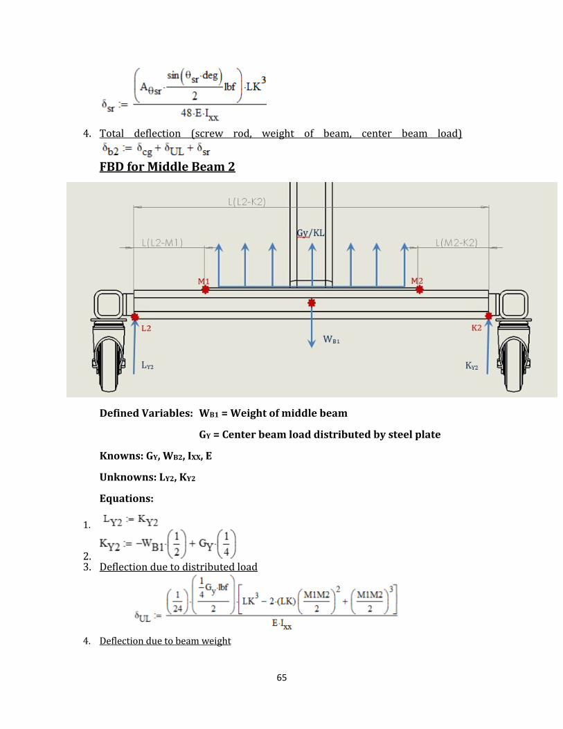
65
4. Total deflection (screw rod, weight of beam, center beam load)
FBD for Middle Beam 2
Defined Variables: WB1 = Weight of middle beam
GY = Center beam load distributed by steel plate
Knowns: GY, WB2, IXX, E
Unknowns: LY2, KY2
Equations:
1.
2. 3. Deflection due to distributed load
4. Deflection due to beam weight

66
5. Total Deflection
FBD for Base Frame
Defined Variables: WBase = Weight of base WS1 = Load due to
middle beam 1
WS2 = Load due to middle beam 2
Knowns: AϴSR, WS1, WS2, WBase
Unknowns: IY, JY
Equations:
1. Deflection due to beam weight
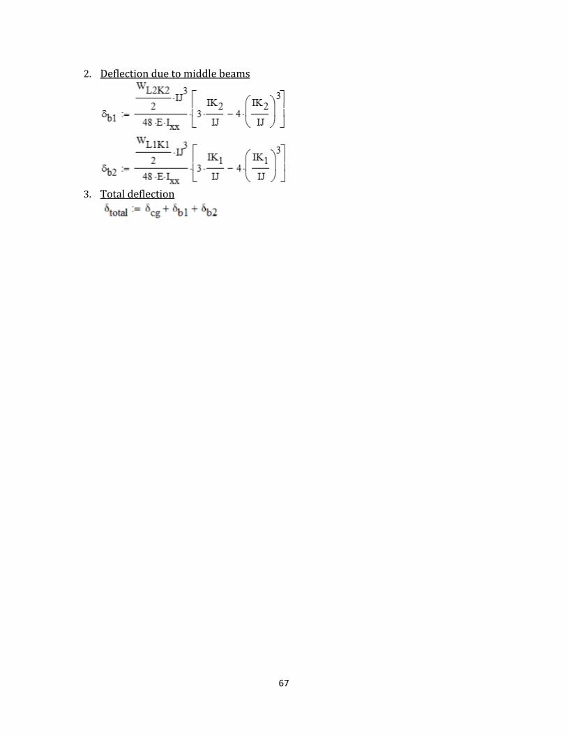
67
2. Deflection due to middle beams
3. Total deflection
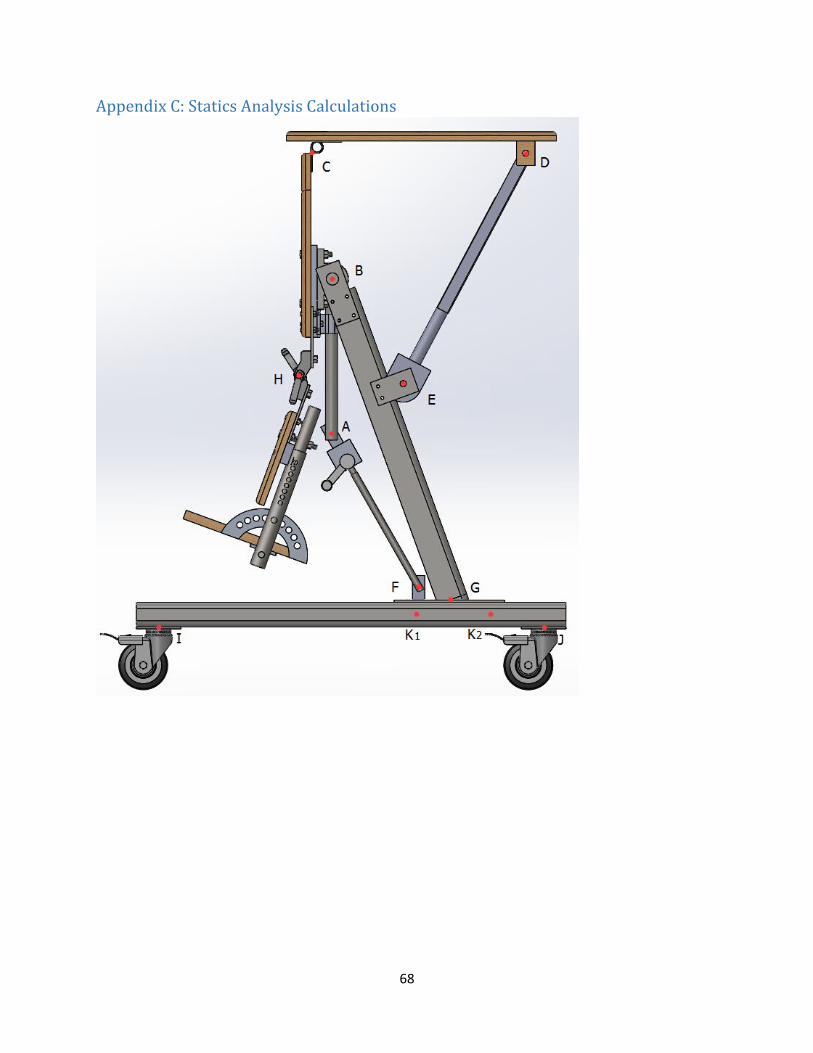
68
Appendix C: Statics Analysis Calculations

69
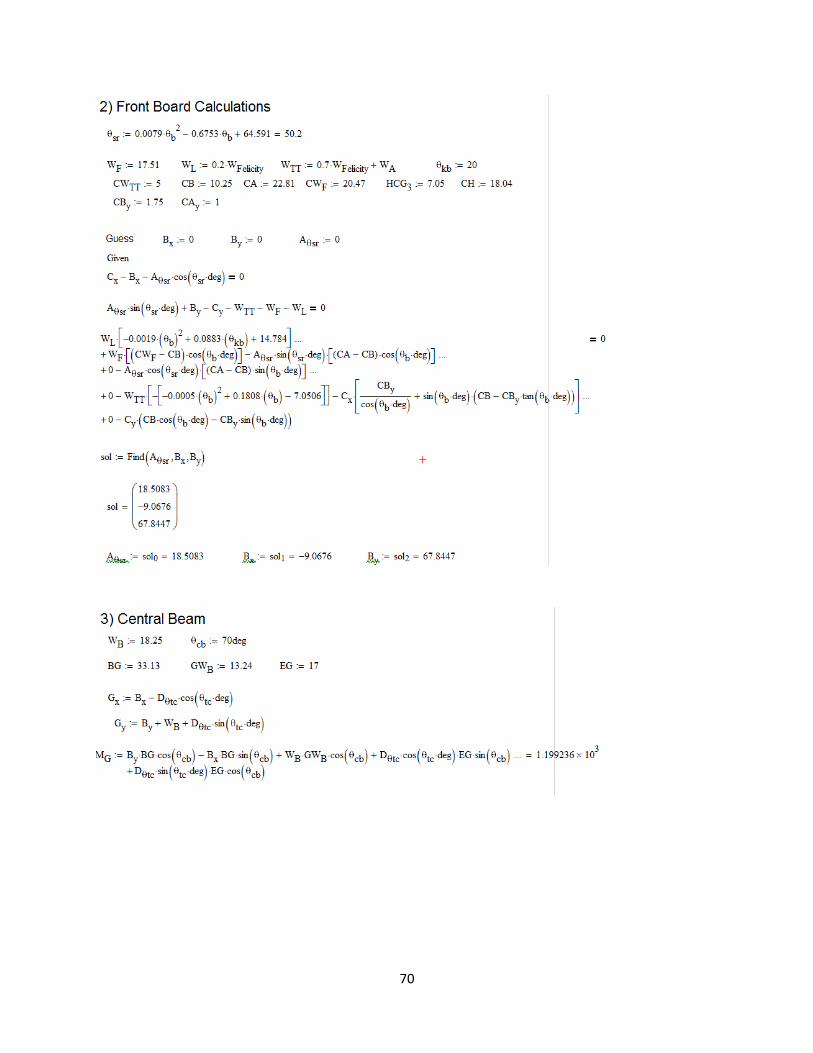
70

71
Appendix D: Stress Analysis Calculations

72

73
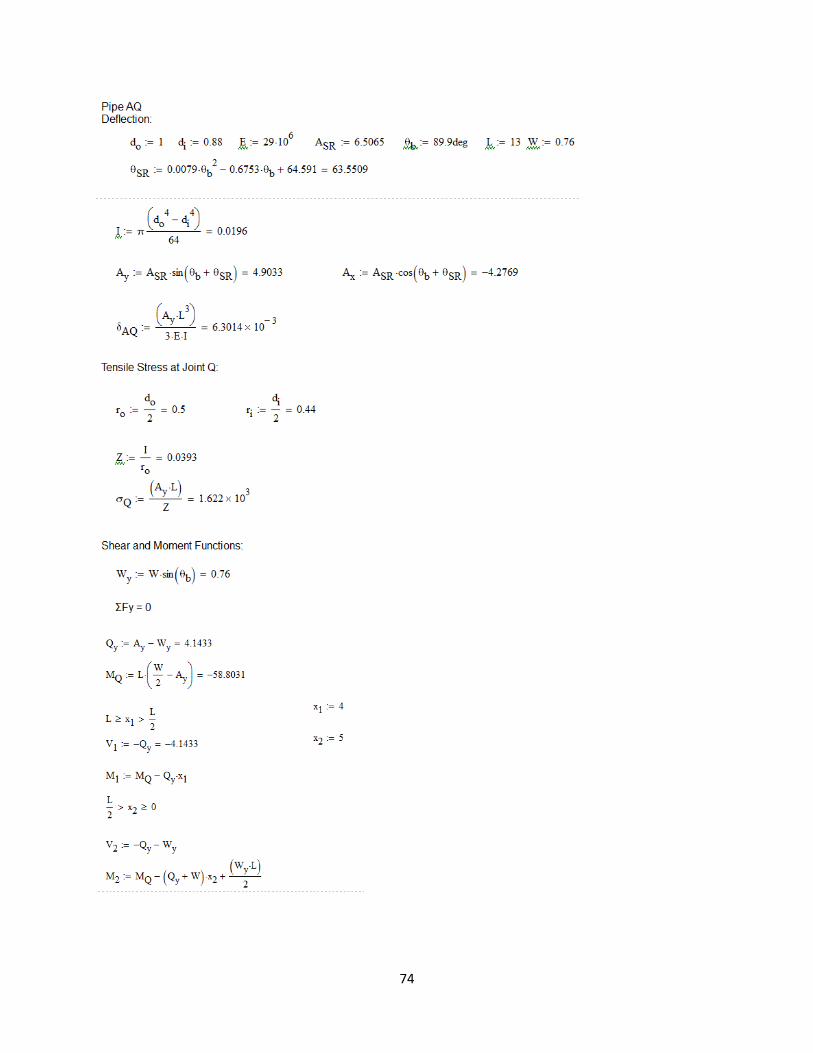
74
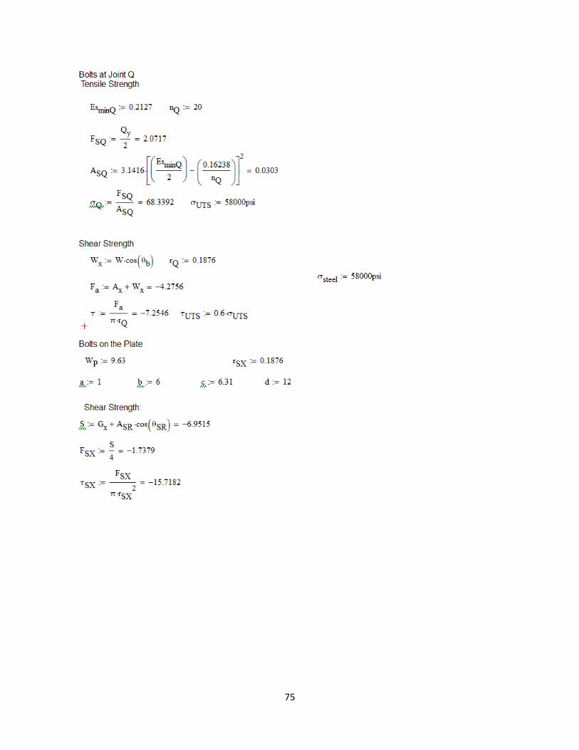
75
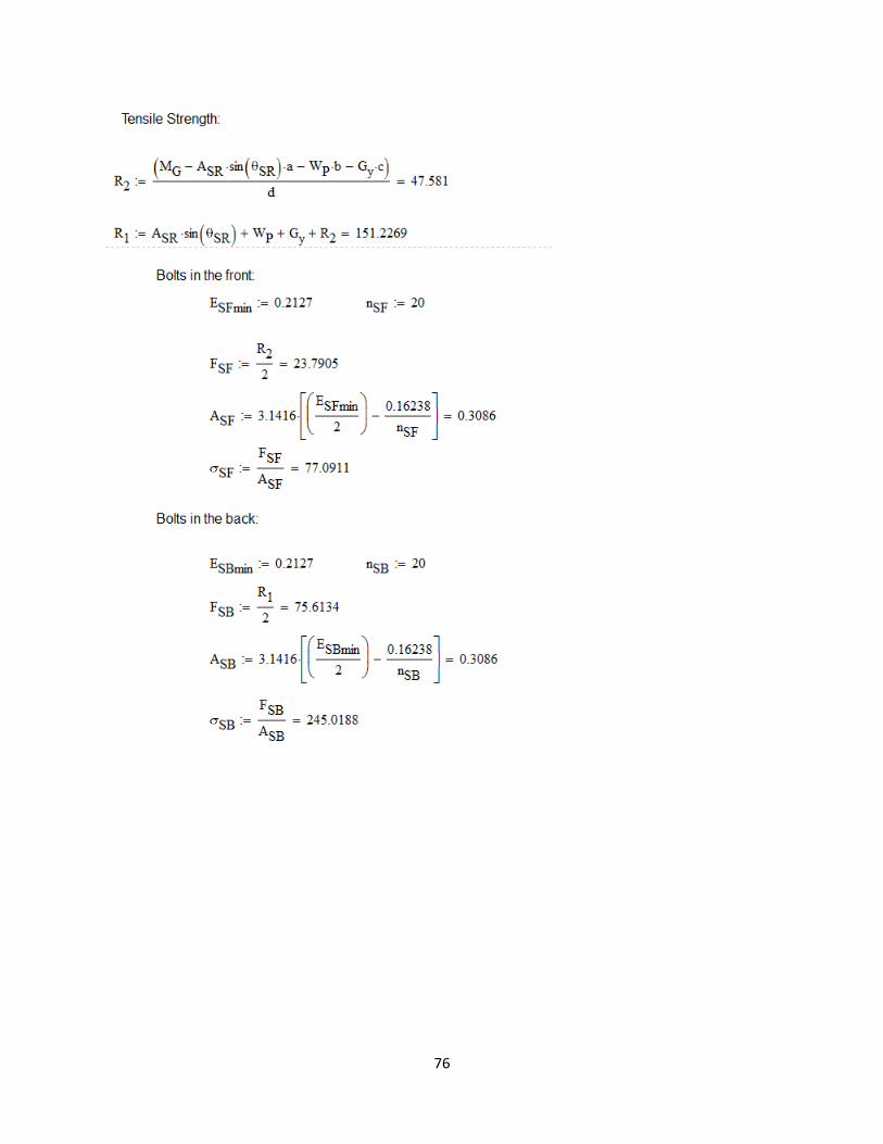
76

77
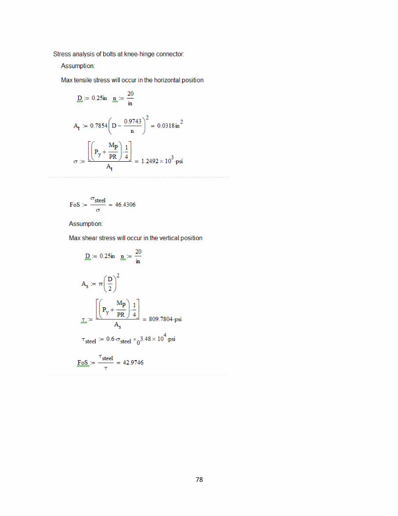
78

79

80
Appendix E: Prototype testing Protocols
Basic Functionality Test Protocols
The following test protocols are to be carried out in sequential order, each involving the use of
the device in a locked, stationary position. During the tests, the device will be equipped with 180 lbs. of weight distributed about the front-board [B] to simulate an oversized user.
Test 1: Front-Board Range of Motion/Functionality
PURPOSE: To confirm the angular range of the Front-Board and the force required to adjust
this angle.
MATERIALS: Standing device, 180 lbs. of weight, and goniometer.
PROCEDURE:
Position the front-board [B] in its most vertical position (perpendicular with the ground).

81
Rotate the handle of the device to change the angle of the front-board [B], recording the
force/effort/number of rotations, required to position the front-board [B] at its most recessed angle of 45° with the ground.
Test 2: Knee-Board Range of Motion/Functionality
PURPOSE: To confirm the angular range of the Knee-Board and the force supported by the
hinges supporting this component.
MATERIALS: Standing device, 60 lbs. of weight, and goniometer.
PROCEDURE:
With the front-board [B] of the device in its most vertical position (perpendicular with the
ground), position the knee-board [C] in its most horizontal position (parallel with the ground).
Apply weight to the knee-board in 10 lb. increments, stopping at 60 lbs.
Tipping Test Protocols
The following test protocols are to be carried out in sequential order, each involving the use of
the device in a locked, stationary position. During the tests, the device will not be equipped
with any additional weight, to simulate minimum forces required to alter the equilibrium of the device.
Test 1: External Force Tipping Stability
PURPOSE: Confirm the stability of the device when positioned on an ADA standard ramp (5 degrees) while device is subject to external forces.
MATERIALS: Standing device, Force Gauge and Wood Sheets (materials to build ramp).
PROCEDURE:
Construct a 5° ramp using wood sheets located in the Rehab Lab.
Position the device so that the front-board [B] of the device sits perpendicular to the inclination
of the ramp.
Using the adjustability features on the device, rotate the front-board [B] to an angle of 45° to
ensure that the following testing is completed with the user’s center of gravity at its highest
point.
Using the force gauge, apply a force to the highest point along the side of the front-board [B]
until the device begins to tip.
Record the force necessary to accomplish this.
82
Test 2: Internal Force Tipping Stability
PURPOSE: Confirm the stability of the device when positioned on an ADA standard ramp (5 degrees) when an internal force is applied.
MATERIALS: Standing device, Force Gauge and Wood Sheets (materials to build ramp).
PROCEDURE:
Construct a 5° ramp using wood sheets located in the Rehab Lab.
Position the device so that the front-board [B] of the device sits perpendicular to the inclination
of the ramp.
Using the adjustability features on the device, rotate the front-board [B] to an angle of 45° to
ensure that the following testing is completed with the user’s center of gravity at its highest
point.
Using the force gauge, apply a force along the central side of the hinge connecting the front-board to the thigh-board [2] until the device begins to tip.
Record the force necessary to accomplish this.
Brake Test Protocols
The following test protocols are to be carried out in sequential order, each involving the use of
the device in a locked, stationary position. During the tests, the device will be equipped with 60 lbs. of weight distributed about the front-board [B] to simulate the expected weight of a user.
Test 1: Brake Functionality
PURPOSE: Determine the required amount of force to compromise the locking functionality of the wheels of the device.
MATERIALS: Standing device, 60 lbs. of weight, and Force Gauge.
PROCEDURE:
Position the device on a flat surface with the two front wheels [E] in a locked position and the
two rear wheels in an unlocked position.
Using the force gauge, apply a force at the front-board pivot [1] until the device moves.
Record the force reading at the point of initial wheel displacement.
Lock the previously unlocked rear set of wheels [F] of the device, so that all four wheels are
now in a locked position.
Repeat steps 2 and 3.
83
Caretaker/User Operation Test Protocols
The following test protocols are to be carried out in sequential order, each involving the use of
the device in a locked, stationary position. The tests are to be carried out ONLY in the event
that the device passes the aforementioned tests demonstrating its safe operation.
Test 1: Ease of Transfer (In)
PURPOSE: Evaluate the ease (for the caretaker) of the transfer of a user into the device.
MATERIALS: Standing Device, Felicity (or other simulated user), and Caretaker
PROCEDURE:
Begin with the front-board [B] of the device in a completely vertical position and each of the
casters in their locked state.
Allow the caretaker to load the user into the device, adjusting the device for his/her height and utilizing the fastening features (straps and buckles) of the stander.
Document any difficulties noted by the Caretaker (constantly asking for feedback).
Test 3: Variant Angular Simulation of Tabletop
PURPOSE: Assess the ease of use and adjustment of the tabletop of the device associated with the loading of a user at three critical angles of support.
MATERIALS: Standing Device, Felicity (or other simulated user), Caretaker, Pencil, and Paper.
PROCEDURE:
With the user still in strapped into position within the device, ask the caretaker to rotate the tabletop to a horizontal position.
Allowing the user to rest the entire weight of his/her arms on the upper surface of the tabletop,
provide him/her with a pencil and paper and, using the tabletop as a desk, allow them to draw
or write their name.
At each angular instance, document any difficulties noted by the Caretaker (constantly asking
for feedback) and make note of the following actions shown by the user.
Felicity’s facial expressions
Arm movement
Location of Felicity’s knees, hips, chest, shoulders, and arms
Repeat the previous steps with tabletop superior and anterior angles of 15 degrees.
Test 4: Ease of Transfer (Out)

84
PURPOSE: Evaluate the ease (for the caretaker) of the transfer of a user into the device.
MATERIALS: Standing Device, Felicity (or other simulated user), and Caretaker
PROCEDURE:
Allow the caretaker to remove the user from the device, first removing all of the fastening
features (straps and buckles) of the stander.
Document any difficulties noted by the Caretaker (constantly asking for feedback).

85
Appendix F: Part Drawings
Tray
Front Board

86
Bracket for Telescoping Tubes
Inner Tube for Tray

87
Outer Tube Tray
Knee Board
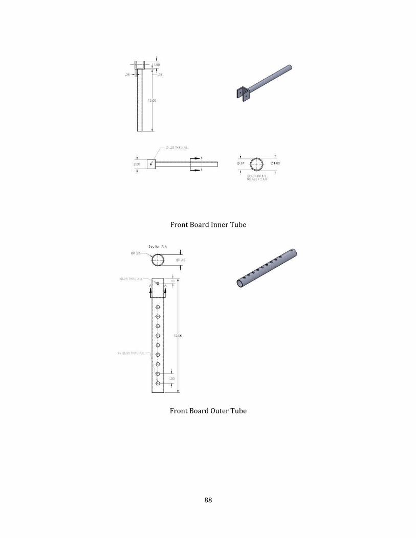
88
Front Board Inner Tube
Front Board Outer Tube

89
Foot Board Angle Adjustment
Foot Board
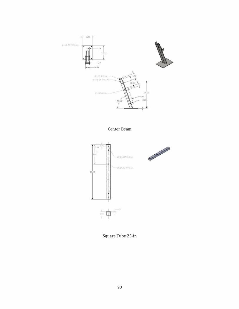
90
Center Beam
Square Tube 25-in

91
Square Tube 35-in

92
Appendix G: Photos of Client and Device
Figure zz Client showing positive reactions while using the standing device

93
Figure aaa A front board inclination closer to horizontal minimizes the weight bared by the user
Figure bbb The device was tested prior to putting the client on it to ensure it was safe to use

94
Appendix H: User Manual for Final Device
Prone Standing Device
User Manual
This device was developed as part of a Major Qualifying Project at WPI by the following students:
Collin Glynn, Michael Guarino, Juan Ordonez, Zhaoyu Zheng
April 29th 2015
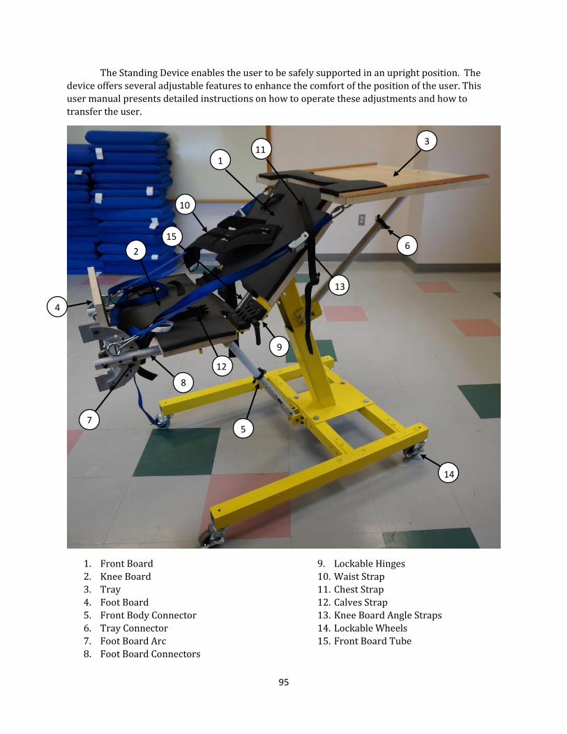
95
The Standing Device enables the user to be safely supported in an upright position. The
device offers several adjustable features to enhance the comfort of the position of the user. This
user manual presents detailed instructions on how to operate these adjustments and how to
transfer the user.
1. Front Board
2. Knee Board
3. Tray
4. Foot Board
5. Front Body Connector
6. Tray Connector
7. Foot Board Arc
8. Foot Board Connectors
9. Lockable Hinges
10. Waist Strap
11. Chest Strap
12. Calves Strap
13. Knee Board Angle Straps
14. Lockable Wheels
15. Front Board Tube
9
8
10
14
5
6
7
1
2
4
3
13
11
12
15

i
General Instructions
A. Adjust the inclination of the Front Board (1) if needed. B. Adjust the inclination of the Knee Board (2) if needed.
C. Adjust the inclination of the tray (3) if needed. D. Adjust the inclination of the Foot Board (4) if needed. E. Adjust the height of the Foot Board if needed. F. Make sure all the adjustments are properly locked. G. Engage the locks on all wheels (14). H. Transfer the user on the device.
A. Adjusting Inclination of Front Board
The inclination of the Front Board is set by adjusting the length of the Foot Board Connector (5).
The following instructions provide step by step procedure to complete this task.
1. WARNING! It is not safe to adjust the inclination of the Front Board while the device is being used.
2. Remove the safety pin from the hole it is in. 3. Firmly hold the Front Board Tube (15) 4. Pull on the lever of the black clamp to unclamp it. 5. Slowly adjust the inclination of the Front Board by either pulling up or pushing down until
the desired position is reached. 6. Re-clamp the clamp by pushing the lever down. Make sure the tubes are tightly clamped. 7. Put the safety pin back in the hole closest to the bottom of the inside tube.
B. Adjusting Inclination of Knee Board
The inclination of the Knee Board is set by adjusting the Knee Board Angle Straps (13) and the Lockable Hinges (9). The following instructions provide step by step procedure to complete this
task.
1. WARNING! It is not safe to adjust the inclination of the Knee Board while the device is being used.
2. Loosen the Knee Board Angle Straps on both sides by pushing the metal clip and pulling on the strap.
3. Adjust the inclination of the Knee Board to the desired position by using your hands to push it downwards or pull it upwards.
4. Tighten the knee board angle straps as much as possible.
C. Adjusting Inclination of Tray
The inclination of the Tray is set by adjusting the length of the Tray Connector (6). The
following instructions provide step by step procedure to complete this task.
1. Remove any items placed on the table.
2. Firmly hold the tray and pull the lever of the black clamp on the tray connector to unclamp it.
3. Slowly adjust the inclination of the tray to the desired position.
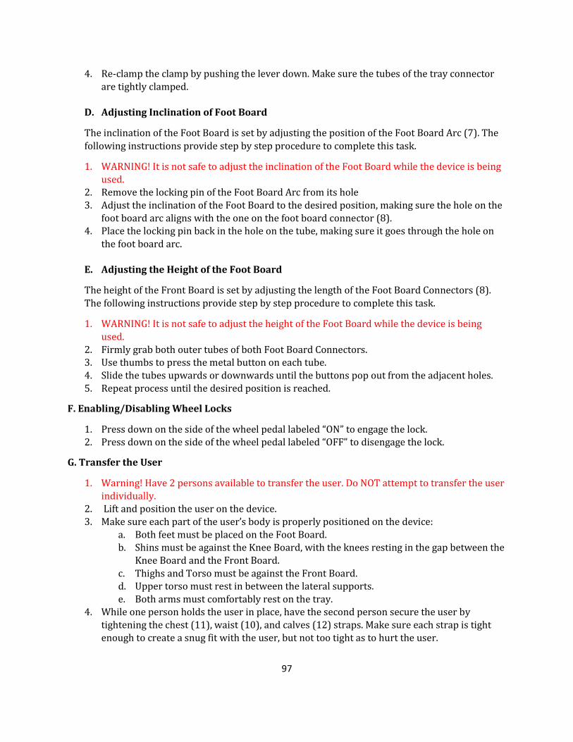
97
4. Re-clamp the clamp by pushing the lever down. Make sure the tubes of the tray connector
are tightly clamped.
D. Adjusting Inclination of Foot Board
The inclination of the Foot Board is set by adjusting the position of the Foot Board Arc (7). The
following instructions provide step by step procedure to complete this task.
1. WARNING! It is not safe to adjust the inclination of the Foot Board while the device is being used.
2. Remove the locking pin of the Foot Board Arc from its hole 3. Adjust the inclination of the Foot Board to the desired position, making sure the hole on the
foot board arc aligns with the one on the foot board connector (8). 4. Place the locking pin back in the hole on the tube, making sure it goes through the hole on
the foot board arc.
E. Adjusting the Height of the Foot Board
The height of the Front Board is set by adjusting the length of the Foot Board Connectors (8).
The following instructions provide step by step procedure to complete this task.
1. WARNING! It is not safe to adjust the height of the Foot Board while the device is being used.
2. Firmly grab both outer tubes of both Foot Board Connectors. 3. Use thumbs to press the metal button on each tube. 4. Slide the tubes upwards or downwards until the buttons pop out from the adjacent holes.
5. Repeat process until the desired position is reached.
F. Enabling/Disabling Wheel Locks
1. Press down on the side of the wheel pedal labeled “ON” to engage the lock. 2. Press down on the side of the wheel pedal labeled “OFF” to disengage the lock.
G. Transfer the User
1. Warning! Have 2 persons available to transfer the user. Do NOT attempt to transfer the user individually.
2. Lift and position the user on the device. 3. Make sure each part of the user’s body is properly positioned on the device:
a. Both feet must be placed on the Foot Board. b. Shins must be against the Knee Board, with the knees resting in the gap between the
Knee Board and the Front Board.
c. Thighs and Torso must be against the Front Board. d. Upper torso must rest in between the lateral supports. e. Both arms must comfortably rest on the tray.
4. While one person holds the user in place, have the second person secure the user by tightening the chest (11), waist (10), and calves (12) straps. Make sure each strap is tight enough to create a snug fit with the user, but not too tight as to hurt the user.

98
5. To remove the user from the device, have one person hold the user in place while the
second person unbuckles the straps. Carefully lift the user out of the device.