standards border templatedownloads.semi.org/web/wstdsbal.nsf/2c1bceb05c9a0e... · web viewasme...
TRANSCRIPT

Background Statement for SEMI Draft Document #4400CRevision to SEMI S18-1102: Environmental, Health and Safety Guideline for Silane Family Gases Handling with title change to “Environmental, Health and Safety Guideline for Flammable Silicon Compounds” Note: This background statement is not part of the balloted item. It is provided solely to assist the recipient in reaching an informed decision based on the rationale of the activity that preceded the creation of this document.
Note: Recipients of this document are invited to submit, with their comments, notification of any relevant patented technology or copyrighted items of which they are aware and to provide supporting documentation. In this context, “patented technology” is defined as technology for which a patent has issued or has been applied for. In the latter case, only publicly available information on the contents of the patent application is to be provided.
Background Statement:
This is the fourth technical ballot for revision to SEMI S18-1102.
After an attempt to pass S18 with minimal editorial revision failed, discussions on how we should revise the document to make the document useful and up-to-date for not only semiconductor manufacturing related use but also other electronics manufacturing (for example, FPD, PV) were held a couple of times in various venues.
It was also intensely discussed how the Safety Guideline should address quite different chemical and physical properties of so called “Silane Family Gases” in current SEMI S18.
As the result of above discussions the document was intensively rewritten to cover safety criteria needed to be observed for each class of flammable silicon compounds covered by the new scope. Although the second ballot, 4400A, received many negatives, it seemed that new scope and structure of the document were generally accepted by the global EH&S committee.
There were still number of technically persuasive negatives and comments on the third ballot, 4400B, and it was failed as TF recommended.
In the following ballot, TF tries to incorporate all the TF’s responses to negatives and comments on 4400B while keeping direction of revising S18 same as the previous ballot.
Because of the extent of the changes from S18-1102, the changes are not identified within this ballot. You are to vote to Accept or Reject replacing the currently-published SEMI S18 with what is in this ballot.
The voting result of Doc.4400C will be reviewed by the S18 Revision Task Force (date is TBD). The formal adjudication of this ballot is scheduled for the EHS Committee meeting, September 26, 2011 at SEMI Japan. Anyone wishing to participate in the discussions should advise Supika Mashiro, Moray Crawford (TF co-leaders), Eric Sklar (NA Support TF leader) or SEMI Staff responsible for EH&S, so that the leaders can ensure that the individual is added to the TF Roster and advised of the teleconference access information and the availability of drafts for review.
If you have any questions, please contact the following TF leaders or SEMI staff:
S18 Revision TF co-leaders:Supika Mashiro (TOKYO ELECTRON LTD.); e-mail: [email protected],Moray Crawford (Hatsuta Seisakusho); e-mail: [email protected]
S18 Revision NA Support TF leader:Eric Sklar (Safety Guru); e-mail: [email protected]
SEMI staff:Akiko Yamamoto (SEMI Japan); e-mail: [email protected]

Safety Checklist for SEMI Draft Document #4400CRevision to SEMI S18-1102: Environmental, Health and Safety Guideline for Silane Family Gases Handling with title change to “Environmental, Health and Safety Guideline for Flammable Silicon Compounds”
Developing/Revising BodyName/Type: S18 Revision Task ForceTechnical Committee: EHSRegion: Japan
LeadershipPosition Last First AffiliationLeader Mashiro Supika TOKYO ELECTRON LTD.Leader Crawford Moray Hatsuta SeisakushoAuthor/Editor* Sklar Eric Safety Guru, LLCChecklist Author** Only necessary if different from leaders
Documents, Conflicts, and ConsiderationSafety related codes, standards, and practices used in developing the safety guideline, and the manner in which each item was considered by the technical committee# and Title Manner of ConsiderationSEMI F1 Referenced applicable criteria.SEMI F6 Referenced applicable criteria.SEMI F5 Referenced applicable criteria.SEMI S1 Referenced applicable criteria.SEMI S2 Referenced applicable criteria.SEMI S4 Referenced applicable criteria.SEMI S5 Referenced applicable criteria.SEMI S6 Referenced applicable criteria.SEMI S10 Referenced applicable criteria.SEMI S13 Referenced applicable criteria.SEMI S14 Referenced applicable criteria.ASME B31.3 Referenced applicable criteria.ASTM Manual, MNL33 “Manual on Chlorosilane Emergency Response Guidelines”
Referenced applicable criteria.
ISO 10156 Referenced applicable criteria.ISO 10298 Referenced applicable criteria.NFPA 1 Referenced applicable criteria.NFPA 70 — National Electrical Code (NEC)
Referenced applicable criteria.
NFPA318 Referenced applicable criteria.CGA G13 Referenced applicable criteria.CGA P20 Referenced applicable criteria.CGA P23 Referenced applicable criteria.29CFR 1900.1200 Referenced applicable criteria.Pressure Equipment Directive 97/23/EC
Referenced applicable criteria.
High Pressure Gas Safety Law Referenced applicable criteria.

KHK Application Guide for the High Pressure Gas Safety Law
Referenced applicable criteria.
NIOSH Pocket Guide Referenced applicable criteria.FM Global Property Loss Prevention Sheets 7-7R “SEMICONDUCTOR FABRICATION FACILITIES”
Referenced applicable criteria.
Known inconsistencies between the safety guideline and any other safety related codes, standards, and practices cited in the safety guideline# and Title Inconsistency with This Safety GuidelineHigh Pressure Gas Safety Law Definition of “highly toxic”, “toxic”, “high pressure gas”
Other conflicts with known codes, standards, and practices or with commonly accepted safety and health principles to the extent practical# and Title Nature of Conflict with This Safety Guideline
Participants and ContributorsLast First AffiliationSakura Hidetoshi IntelSugihara Kenichi Taiyo NissanIbuka Shigehito TELYamauchi Yasuhiro Mitsubishi Heavy IndustriesFessler Mark TELNgai Eugene Chemically Speaking LLCFunk Rowland SalusDesrosiers Robert IBMSexton David TUV RNANogawa Kaoru Safe TechnoLarson Sean LAMClane Lauren AMATYakimow Byron Cymer
The content requirements of this checklist are documented in Section 14.2 of the Regulations Governing SEMI Standards Committees.

LETT
ER (Y
ELLO
W) B
ALL
OT
Informational (Blue) Ballot1000A
SEMI Draft Document #4400CRevision to SEMI S18-1102: Environmental, Health and Safety Guideline for Silane Family Gases Handling with title change to “Environmental, Health and Safety Guideline for Flammable Silicon Compounds”
1 Purpose1.1 This Safety Guideline is intended as a minimum set of safety and health criteria for storage, handling, and use of flammable silicon compounds from supply to abatement.
1.2 This guideline is also intended as a minimum set of safety and health design criteria for semiconductor, FPD, PV manufacturing equipment and other equipment that uses flammable silicon compounds for processing.
2 Scope2.1 Flammable silicon compounds that are within the scope of this Safety Guideline are shown in Table 1.
Table 1 Chemicals Within the Scope of This Safety Guideline
Compressed Gas Liquefied Gas Liquid
Not Corrosive monosilane disilanemonomethylsilane
dimethylsilanetrimethylsilane
trisilanetetramethylsilane
Corrosive monochlorosilanedichlorosilane
trichlorosilane methylchlorosilane
methyldichlorosilane dimethyldichlorosilane methyltrichlorosilane
1: The term “chemicals” includes liquids and gases.
2: “Silane” without modifiers usually means silicon tetrahydride. The synonym “monosilane” is also used for clarification.
2.2 Flammable mixtures containing flammable silicon compounds included in the Table 1 are also within the scope of this Safety Guideline.
3: Silane is often mixed with highly toxic flammable gas such as phosphine. In such case additional requirements apply.
2.3 This Safety Guideline includes the following sections:
1. Purpose
2. Scope
3. Limitations
4. Referenced Standards and Documents
5. Terminology
6. General Principles
7. Evaluation
8. Education and Training
9. Emergency Response
10. Offline Storage Facilities
This is a draft document of the SEMI International Standards program. No material on this page is to be construed as an official or adopted standard. Permission is granted to reproduce and/or distribute this document, in whole or in part, only within the scope of SEMI International Standards committee (document development) activity. All other reproduction and/or distribution without the prior written consent of SEMI is prohibited.
Page 1 Doc. 4400C SEMI
Semiconductor Equipment and Materials International3081 Zanker RoadSan Jose, CA 95134-2127Phone:408.943.6900 Fax: 408.943.7943
DRAFTDocument Number: 4400C
Date: 5/6/2023

LETT
ER (Y
ELLO
W) B
ALL
OT
Informational (Blue) Ballot1000A11. Supply from Outdoor Storage/Dispensing Facilities
12. Supply from Indoor Storage/Dispensing Facilities
13. Indoor Distribution System
14. Equipment Using Flammable Silicon Compounds
15 Exhaust Ventilation, Flammable Silicon Compound Effluent, and Abatement Systems
Appendix 1 ― System Configurations – Cylinder sources
Appendix 2 ― System Configuration – Bulk Sources
Appendix 3 ― Piping and Flow Components
Appendix 4 ― Pressurization Testing and Leak Testing
Appendix 5 ― Gas Monitoring
Appendix 6 ― Fire Detection, Suppression, and Alarm Systems
4: This Safety Guideline contains the following Related Information sections: Related Information 1 ― Physical and Chemical Properties of Flammable Silicon Compounds Commonly Used in
Semiconductor, FPD, and PV Manufacturing Related Information 2 ― Silane Safety Control Systems
2.4 In some sections of this Safety Guideline, as well as in some of the included supplementary materials, the columns to the right of the text designate to which flammable silicon compounds the text applies. In the headers of those columns: “CG” designates “compressed gas”, “LG” designates “liquefied compressed gas”, and “L” designates “liquid”. Where there are no such columns, the material applies to all of the flammable silicon compounds included in the Scope of this document.
NOTICE: This safety guideline does not purport to address all of the safety issues associated with its use. It is the responsibility of the users of this safety guideline to establish appropriate safety and health practices and determine the applicability of regulatory or other limitations prior to use.
3 Limitations3.1 This document is not intended to apply to facilities of gas manufacturers or distribution companies or to operations in those facilities.
4 Referenced Standards and Documents4.1 SEMI Standards and Safety Guidelines
SEMI F1 — Specification for Leak Integrity of High-Purity Gas Piping Systems and Components
SEMI F5 — Guide for Gaseous Effluent Handling
SEMI F6 — Guide for Secondary Containment of Hazardous Gas Piping Systems
SEMI S1 — Safety Guideline for Equipment Safety Labels
SEMI S2 — Environmental, Health, and Safety Guideline for Semiconductor Manufacturing Equipment
SEMI S4 — Safety Guideline for the Separation of Chemical Cylinders Contained in Dispensing Cabinets
SEMI S5 — Safety Guideline for Sizing and Identifying Flow Limiting Devices for Gas Cylinder Valves
SEMI S6 — EHS Guideline for Exhaust Ventilation of Semiconductor Manufacturing Equipment
SEMI S10 Safety Guideline for Risk Assessment and Risk Evaluation Process
SEMI S13 Environmental, Health and Safety Guideline for Documents Provided to the Equipment User for Use with Semiconductor Manufacturing Equipment
This is a draft document of the SEMI International Standards program. No material on this page is to be construed as an official or adopted standard. Permission is granted to reproduce and/or distribute this document, in whole or in part, only within the scope of SEMI International Standards committee (document development) activity. All other reproduction and/or distribution without the prior written consent of SEMI is prohibited.
Page 2 Doc. 4400C SEMI
Semiconductor Equipment and Materials International3081 Zanker RoadSan Jose, CA 95134-2127Phone:408.943.6900 Fax: 408.943.7943
DRAFTDocument Number: 4400C
Date: 5/6/2023

LETT
ER (Y
ELLO
W) B
ALL
OT
Informational (Blue) Ballot1000ASEMI S14 Safety Guidelines for Fire Risk Assessment and Mitigation for Semiconductor Manufacturing Equipment
4.2 ASME Standard1
ASME B31.3 Standards for Pressure Piping Process Piping
4.3 Compressed Gas Association2
CGA G-13 Storage and Handling of Silane and Silane Mixtures
CGA P-20 — Standard for the Classification of Toxic Gas Mixtures
CGA P-23 Standard for Categorizing Gas Mixtures Containing Flammable and Nonflammable Components
4.4 ISO Standards3
ISO 10156 Gases and gas mixtures -- Determination of fire potential and oxidizing ability for the selection of cylinder valve outlets
ISO 10298 — Determination of toxicity of a gas or gas mixture
4.5 National Fire Protection Association (NFPA) Standards4
NFPA 1 — Fire Code
NFPA 70 — National Electrical Code (NEC)
NFPA 318 Standard for the Protection of Semiconductor Fabrication Facilities
4.6 US Code of Federal Regulations
29CFR 1910.12005 Hazard Communication (OSHA)
4.7 EU Directive
Pressure Equipment Directive 97/23/EC
4.8 Other Documents
ASTM Manual, MNL33 “Manual on Chlorosilane Emergency Response Guidelines”
FM Global Property Loss Prevention Sheets 7-7R “SEMICONDUCTOR FABRICATION FACILITIES”6
High Pressure Gas Safety Law7
The High Pressure Gas Safety Institute of Japan (KHK), Application Guide for the High Pressure Gas Safety Law8
NIOSH Pocket Guide9
NOTICE: Unless otherwise indicated, all documents cited shall be the latest published versions.
5 Terminology5.1 Refer to the Terminology defined in SEMI S2 except for terms specified below.
5.2 Abbreviations and Acronyms
5.2.1 ESOV Emergency Shut Off Valve1 American Society of Mechanical Engineers, Three Park Avenue, New York, NY 10016-5990 Website: www.asme.org2 Compressed Gas Association, 4221 Walney Road, 5th Floor, Chantilly, VA 20151, Website: www.cganet.com3 International Organization for Standardization, ISO Central Secretariat, 1 rue de Varembé, Case postale 56, CH-1211 Geneva 20, Switzerland. Telephone: 41.22.749.01.11; Fax: 41.22.733.34.30; http://www.iso.ch4 National Fire Protection Association, 1 Batterymarch Park, PO Box 9101, Quincy, MA 02269-9101 Website: www.nfpa.org5 Occupational Safety and Health Administration,U.S. Department of Labor, http://www.osha.gov6 FM Global, http://www.fmglobal.com7 KHK, Sumitomo-Tranomon Bldg., 4-3-9 Toranomon, Minatoku, Tokyo 105-84478 KHK, Sumitomo-Tranomon Bldg., 4-3-9 Toranomon, Minatoku, Tokyo 105-84479 Centers for Disease Control and Prevention, Website: www.cdc.gov/Niosh/
This is a draft document of the SEMI International Standards program. No material on this page is to be construed as an official or adopted standard. Permission is granted to reproduce and/or distribute this document, in whole or in part, only within the scope of SEMI International Standards committee (document development) activity. All other reproduction and/or distribution without the prior written consent of SEMI is prohibited.
Page 3 Doc. 4400C SEMI
Semiconductor Equipment and Materials International3081 Zanker RoadSan Jose, CA 95134-2127Phone:408.943.6900 Fax: 408.943.7943
DRAFTDocument Number: 4400C
Date: 5/6/2023

LETT
ER (Y
ELLO
W) B
ALL
OT
Informational (Blue) Ballot1000A5.2.2 IDLH Immediately Dangerous to Life and Health
5.2.3 MAWP Maximum Allowable Working Pressure
5.2.4 MOP Maximum Operating Pressure
5.2.5 MSDS Material Safety Data Sheet
5.2.6 PTFE Polytetrafluoroethylene
5.2.7 TLV® Threshold Limit Value for a chemical substances in the work environment adopted by ACGIH®
(TLV® is a registered trademark of the American Conference of Governmental Industrial Hygienists.) [SEMI F6]
5.2.8 TWA — Time Weighted Average
5.2.9 VMB — Valve Manifold Box
5.3 Definitions
5.3.1 abatement system — a system used to modify the effluent from a process in order to reduce emissions of hazardous materials to levels that do not present unacceptable risk.
5.3.2 bulk able to contain 454L (volume of 0.5 US tons of water) or more.
NOTE 2: The volume is of the container, not the volume of gas or liquid.
5.3.3 carriage a hand cart for carrying one or two gas cylinders.
5.3.4 chlorosilane any substance designated in Table 1 as being corrosive.
5.3.5 compressed gas— a gas that exerts a gauge pressure of 200 kPa (29.0 psig/43.8 psia) or greater at 20 °C (68 °F).
5.3.6 controlled condition when related to flammable silicon compounds, a condition in which the chemical is controlled within the confines of an approved piping system with controls that can determine if the safe parameters of the piping system have failed.
5.3.7 exhaust ventilation any of primary, secondary, or additional exhaust ventilation (that is, PEV, SEV, or AEV), as defined herein. [SEMI S6]
5.3.7.1 primary exhaust ventilation (PEV) airflow that, in normal operation, extracts substances of concern from the equipment. [SEMI S6]
5.3.7.2 secondary exhaust ventilation (SEV) airflow that, in normal operation of the equipment, does not extract substances of concern, but operates continuously to extract substances of concern should they be released from their primary containment due to failure or to maintenance or service operations. [SEMI S6]
5: For example, the exhaust ventilation through gas panels is considered SEV, because in normal operation, the hazardous gases are within their piping and only under failure, maintenance, or service are hazardous gases removed by the exhaust ventilation.
5.3.7.3 additional exhaust ventilation (AEV) airflow that is not present during normal operation but is provided to extract substances of concern during maintenance or in the case of an abnormal release from primary containment. [SEMI S6]
5.3.8 flammable mixture — any mixture that forms an ignitable mixture in air at 20°C (68°F) and 101.3 kPa (14.7 psia). This includes, by definition, any pyrophoric mixture. (As used in this definition, “an ignitable mixture in air” is a mixture that can be ignited.)
6:ISO10156 provides information on how to decide if a mixture is flammable or not.
5.3.9 flammable silicon compounds — within this document, the chemicals listed in Table 1.
5.3.10 flammable silicon compound effluent — flammable silicon compounds or mixtures of flammable silicon compounds with process gases, purge gases, or process byproducts, but not with air, for which there is no intended use in the manufacturing processes.
This is a draft document of the SEMI International Standards program. No material on this page is to be construed as an official or adopted standard. Permission is granted to reproduce and/or distribute this document, in whole or in part, only within the scope of SEMI International Standards committee (document development) activity. All other reproduction and/or distribution without the prior written consent of SEMI is prohibited.
Page 4 Doc. 4400C SEMI
Semiconductor Equipment and Materials International3081 Zanker RoadSan Jose, CA 95134-2127Phone:408.943.6900 Fax: 408.943.7943
DRAFTDocument Number: 4400C
Date: 5/6/2023

LETT
ER (Y
ELLO
W) B
ALL
OT
Informational (Blue) Ballot1000A5.3.11 flow components components (such as valves regulators, pressure gauges, elbows, and tees) used in a piping system that normally come in contact with the chemical flowing in the piping system.
5.3.12 flow limiting device a device that will reduce maximum flow rate under full flow conditions. [SEMI S5]
7: One such device is a Restricted Flow Orifice (RFO).
5.3.13 gas cylinder — a cylindrical container of less than 454 L volume used to store, transport, or dispense compressed gases and liquefied compressed gases.
5.3.14 highly toxic having a median lethal concentration (LC50) in air of 200 parts per million by volume or less of gas or vapor, or 2 milligrams per liter or less of mist, fume, or dust, when administered by continuous inhalation for one hour (or less if death occurs within one hour) to albino rats weighing between 200 and 300 grams each.
5.3.15 immediately dangerous to life and health (IDLH) the concentration of airborne contaminants, normally expressed in parts per million or milligrams per cubic meter, which represents the maximum level from which one could escape within thirty minutes without any escape-impairing symptoms or irreversible health effects. This level is established by the National Institute of Occupational Safety and Health (NIOSH). [SEMI F6]
8: OSHA has the following definition “An atmospheric concentration of any toxic, corrosive or asphyxiant substance that poses an immediate threat to life or would cause irreversible or delayed adverse health effects or would interfere with an individual's ability to escape from a dangerous atmosphere.” [29 CFR 1910.120]
5.3.16 inert gas A gas that is not generally reactive (for example, N2 and Ar).
5.3.17 liquefied compressed gas a gas which under the charged pressure is partially liquid at a temperature of 21.1°C (70°F). [SEMI C3]
5.3.18 liquid container a container of less than 454 L volume used to store, transport, or dispense liquids.
5.3.19 maximum allowable working pressure (MAWP) the maximum internal pressure permitted in a vessel or a piping system for continued operation at the most severe condition of coincident internal and external pressure and temperature (minimum or maximum) expected. Its value is limited by the pressure-temperature rating of the equipment and the maximum allowable stress used in the design.
9: MAWP is generally the same as the Design Pressure as defined in ASME B31.3.
5.3.20 maximum operating pressure (MOP) the maximum pressure at which a vessel or piping system is normally operated (that is Process Pressure), generally less than, and never greater than, MAWP.
5.3.21 occupational exposure limit (OEL) the maximum airborne concentration of a substance to which a worker may be exposed for the specified time. OELs include TWAs, STELs, and Ceiling limits, which differ in the time period for which they specify concentrations. Various terms are used to refer to OELs, such as permissible exposure levels, Threshold Limit Values®, maximum acceptable concentrations, maximum exposure limits, and occupational exposure standards. The criteria used in determining OELs can differ among the countries that have established values. [SEMI S6]
5.3.22 offline storage facilities storage facilities for flammable silicon compounds containers (for example, gas cylinders or liquid containers) that are not physically connected to any distribution system.
5.3.23 oxidizer gas a gas which will support combustion or increase the burning rate of a combustible material with which it may come in contact. [SEMI F51]
5.3.24 pyrophoric chemical a chemical which upon contact with air may ignite spontaneously at or below a temperature of 54°C (130°F).
5.3.25 qualified personnel those persons trained and capable of performing activities involving the risks associated with the defined tasks.
5.3.26 safe shutdown condition a condition in which all hazardous energy sources are removed or suitably contained and hazardous production materials are removed or contained, unless this results in increased risk.
This is a draft document of the SEMI International Standards program. No material on this page is to be construed as an official or adopted standard. Permission is granted to reproduce and/or distribute this document, in whole or in part, only within the scope of SEMI International Standards committee (document development) activity. All other reproduction and/or distribution without the prior written consent of SEMI is prohibited.
Page 5 Doc. 4400C SEMI
Semiconductor Equipment and Materials International3081 Zanker RoadSan Jose, CA 95134-2127Phone:408.943.6900 Fax: 408.943.7943
DRAFTDocument Number: 4400C
Date: 5/6/2023

LETT
ER (Y
ELLO
W) B
ALL
OT
Informational (Blue) Ballot1000A5.3.27 safe state a condition in which the equipment does not present any unacceptable risk to itself or to personnel. It does not allow hazardous production chemicals to flow. An acceptable safe state is determined by the designer of the equipment and is based on the hazards in the design.
5.3.28 time weighted average — an occupational exposure limit (OEL) for an exposure period of one work shift, typically eight hours. The time period is specified as part of the TWA. [SEMI S6]
5.3.29 toxic having a median lethal concentration (LC50) in air of more than 200 parts per million but not more than 2,000 parts per million by volume of gas or vapor, or more than 20 milligrams per liter but not more than 200 milligrams per liter of mist, fume, or dust, when administered by continuous inhalation for one hour (or less if death occurs within one hour) to albino rats weighing between 200 and 300 grams each.
5.3.30 unacceptable risk — a risk of Medium, High, or Very High as defined by SEMI S10 or S14.
5.3.31 unsafe gas condition a condition with a risk of Medium, High, or Very High as defined by SEMI S10 or S14.
6 General PrinciplesNot
Corrosive Corrosive
Paragraph CG LG L CG LG L
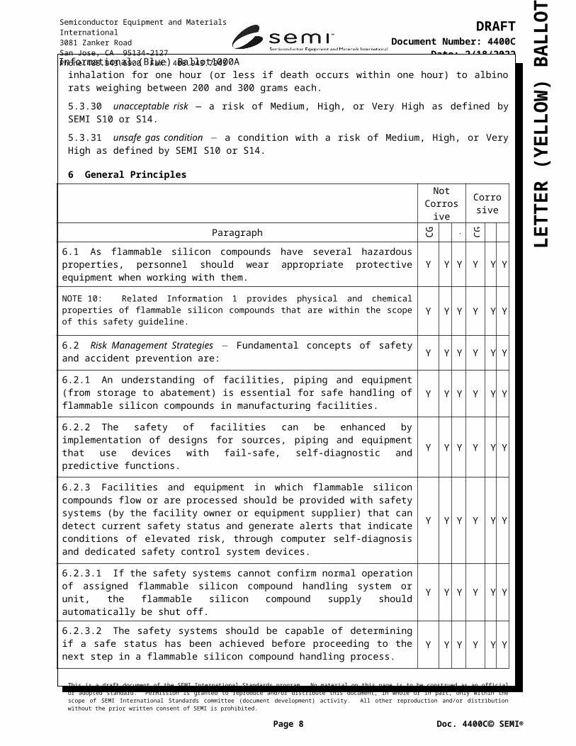
6.1 As flammable silicon compounds have several hazardous properties, personnel should wear appropriate protective equipment when working with them. Y Y Y Y Y Y
10: Related Information 1 provides physical and chemical properties of flammable silicon compounds that are within the scope of this safety guideline. Y Y Y Y Y Y
6.2 Risk Management Strategies Fundamental concepts of safety and accident prevention are: Y Y Y Y Y Y
6.2.1 An understanding of facilities, piping and equipment (from storage to abatement) is essential for safe handling of flammable silicon compounds in manufacturing facilities. Y Y Y Y Y Y
6.2.2 The safety of facilities can be enhanced by implementation of designs for sources, piping and equipment that use devices with fail-safe, self-diagnostic and predictive functions.
Y Y Y Y Y Y
6.2.3 Facilities and equipment in which flammable silicon compounds flow or are processed should be provided with safety systems (by the facility owner or equipment supplier) that can detect current safety status and generate alerts that indicate conditions of elevated risk, through computer self-diagnosis and dedicated safety control system devices.
Y Y Y Y Y Y
6.2.3.1 If the safety systems cannot confirm normal operation of assigned flammable silicon compound handling system or unit, the flammable silicon compound supply should automatically be shut off.
Y Y Y Y Y Y
6.2.3.2 The safety systems should be capable of determining if a safe status has been achieved before proceeding to the next step in a flammable silicon compound handling process.
Y Y Y Y Y Y
6.2.4 Safe design depends on equipment designers’ and facilities designers’ understanding of flammable silicon compounds properties and hazards. Design methods for controlling the risks of these hazards require full integration of measures from all portions of the delivery and use systems.
Y Y Y Y Y Y
6.2.4.1 Safety control systems should be provided in distribution facilities, cylinder cabinets, process equipment, gas treatment systems, and the like. Y Y Y Y Y Y
This is a draft document of the SEMI International Standards program. No material on this page is to be construed as an official or adopted standard. Permission is granted to reproduce and/or distribute this document, in whole or in part, only within the scope of SEMI International Standards committee (document development) activity. All other reproduction and/or distribution without the prior written consent of SEMI is prohibited.
Page 6 Doc. 4400C SEMI
Semiconductor Equipment and Materials International3081 Zanker RoadSan Jose, CA 95134-2127Phone:408.943.6900 Fax: 408.943.7943
DRAFTDocument Number: 4400C
Date: 5/6/2023

LETT
ER (Y
ELLO
W) B
ALL
OT
Informational (Blue) Ballot1000ANot
Corrosive Corrosive
Paragraph CG LG L CG LG L
11: Information on the hazards of flammable silicon compounds is available from various sources, including: regulations, MSDSs, Factory Mutual Loss Prevention Data Sheets, NFPA Standards, consensus building codes, and various research papers. Related Information 1 also provides some information on the hazardous properties of flammable silicon compounds.
Y Y Y Y Y Y
6.2.4.2 The supplier should complete, prior to use, a hazard identification and risk assessment [such as Process Hazard Analysis (PHA), Hazard and Operability Analysis (Haz-Op), Failure Mode Effects Analysis (FMEA)], for all flammable silicon compound systems.
Y Y Y Y Y Y
12: Different analytical methods will identify different system hazards; no single method will find them all. It takes a combination of techniques for thorough hazard identification and risk assessment. Y Y Y Y Y Y
6.2.4.3 The results of the analysis should be reported using the SEMI S10 risk matrix. Y Y Y Y Y Y
6.2.5 Minimization of Quantity The quantity of any flammable silicon compounds online and in use should be limited to the smallest amount necessary for effective production. This can be achieved, for example, by the introduction of restrictive flow orifices within equipment or in facility supply lines.
Y Y Y Y Y Y
6.2.6 Periodic accident prevention assessments should be performed to assist in minimizing incident frequency. Y Y Y Y Y Y
6.3 Hazardous Energy Isolation (Lockout/Tagout)
6.3.1 Hazardous energy isolation (previously called “lock out/tag out”) capability should be provided for all flammable silicon compound sources at all levels necessary to perform service or maintenance on flammable silicon compound systems safely.
Y Y Y Y Y Y
6.3.2 Hazardous energy isolation of all other energy sources (for example, electrical, mechanical) should be performed, as necessary, to provide safety for personnel working on systems associated with flammable silicon compounds.
Y Y Y Y Y Y
13:It may not be necessary to isolate non-hazardous voltage and non-hazardous power energy sources if piping systems associated with flammable silicon compounds have been isolated and purged sufficiently prior to opening the containment.
6.4 All personnel concerned in flammable silicon compound handling should be trained for the jobs they are to perform and the hazards to which they will be exposed. All such training should be formally documented and, if regulations apply, the documentation should be in accordance with the regulations.
Y Y Y Y Y Y
6.4.1 Inspection of system status and equipment condition should be performed and documented on a periodic basis.
Y Y Y Y Y Y
6.4.2 The operator or technician should be capable of checking the current status and any abnormal condition before beginning work on any system or subsystem.
Y Y Y Y Y Y
6.5 Evacuation and Purging
6.5.1 When connecting flammable silicon compounds' piping to equipment, the piping should be purged with inert gas, such as nitrogen, into a safe location to prevent the reaction of air with flammable silicon compounds.
Y Y Y Y Y Y
This is a draft document of the SEMI International Standards program. No material on this page is to be construed as an official or adopted standard. Permission is granted to reproduce and/or distribute this document, in whole or in part, only within the scope of SEMI International Standards committee (document development) activity. All other reproduction and/or distribution without the prior written consent of SEMI is prohibited.
Page 7 Doc. 4400C SEMI
Semiconductor Equipment and Materials International3081 Zanker RoadSan Jose, CA 95134-2127Phone:408.943.6900 Fax: 408.943.7943
DRAFTDocument Number: 4400C
Date: 5/6/2023

LETT
ER (Y
ELLO
W) B
ALL
OT
Informational (Blue) Ballot1000ANot
Corrosive Corrosive
Paragraph CG LG L CG LG L
6.5.2 A means of purging should be provided for closed piping systems. If an occasional use purge port is provided for this purpose, it should have a cap or plug to seal the port when it is not connected to the purge gas.
Y Y Y Y Y Y
6.5.3 The user should introduce flammable silicon compounds only after purging oxidizing gases and other incompatible gases, materials or substances from the system.
Y Y Y Y Y Y
6.5.4 Flammable silicon compound systems should have procedures based on calculated minimum purge cycles, minimum purge gas pressures, and necessary vacuum levels to insure the system has been adequately purged before being opened to atmosphere. Calculations are needed to define minimum number of cycles. Process purges typically far exceed this number of cycles, therefore testing is usually not necessary.
Y Y Y Y Y Y
6.5.5 An adequate means should be provided to avoid a cross contamination of purge gases and the process gases by accidental backflow.
Y Y Y Y Y Y
6.5.5.1 Separation of purge gas and any flammable silicon compounds should not depend solely on check valves. A control valve, such as a pneumatic valve placed before or after the check valve, is preferred for isolating flammable silicon compounds from purge gases during procedures that might allow reverse flow.
Y Y Y Y Y Y
6.5.5.2 The purge gas for flammable silicon compounds should be supplied from dedicated higher-than-flammable-silicon-compounds-pressure source.
Y Y Y Y
6.5.5.3 Purge gas pressures should be always greater than process gas pressures to prevent backflow of process gases.
Y Y Y Y
6.5.5.4 The purge gas sources for flammable silicon compounds should not be connected to distribution systems for gases or chemicals that can form an ignitable mixture with flammable silicon compounds.
Y Y Y Y Y Y
14: Some regional codes (for example, Japan’s High Pressure Gas Safety Law) require a purge gas source which is totally separated from the purge gas source for oxidizer gas lines for compressed gas or liquefied compressed gas supply system of flammable silicon compounds.
Y Y Y Y
6.5.5.5 Purge lines from dedicated bulk supplies (where allowed at all by the jurisdiction) should have multi-level back-flow prevention and pressure differential protection to prevent back-flow of flammable silicon compounds into bulk systems.
Y Y Y Y Y Y
15: Back-flow into these bulk purge systems has been known to generate ignitable mixtures when the purge gas is exposed to atmosphere far from the source of contamination.
Y Y Y Y Y Y
This is a draft document of the SEMI International Standards program. No material on this page is to be construed as an official or adopted standard. Permission is granted to reproduce and/or distribute this document, in whole or in part, only within the scope of SEMI International Standards committee (document development) activity. All other reproduction and/or distribution without the prior written consent of SEMI is prohibited.
Page 8 Doc. 4400C SEMI
Semiconductor Equipment and Materials International3081 Zanker RoadSan Jose, CA 95134-2127Phone:408.943.6900 Fax: 408.943.7943
DRAFTDocument Number: 4400C
Date: 5/6/2023

LETT
ER (Y
ELLO
W) B
ALL
OT
Informational (Blue) Ballot1000A
7 Evaluation7.1 Conformance to SEMI S18 of distribution system, process equipment, exhaust ventilation, flammable silicon compound effluent, and abatement systems should be technically evaluated in accordance with the criteria of §8 through §15 that are applicable to the system or equipment under evaluation.
8 Education and Training
16: It is important for managers as well as employees to deepen their understanding of the characteristics of flammable silicon compounds that they handle, so as to ensure safe work practices. If employees do not handle flammable silicon compounds, this section is not applicable.
8.1 Everyone who handles flammable silicon compounds should be specially educated about the hazardous properties and safe handling methods of them.
17: Some jurisdictions (such as Japan, U.S. and Europe) require that users of “specialty high-pressure gases” provide special safety education to their employees.
8.1.1 In regard to safety education and training, each organization should maintain an appropriate program for implementing all the necessary education and training, assign a person responsible for education and training, and implement a periodic training plan.
8.1.2 Instructors should be persons who have sufficient knowledge and experience about the hazards, use and safe control of flammable silicon compounds.
18: It may be necessary to obtain the assistance of outside experts, depending on an organization’s capabilities.
8.1.3 Training should include safe use, handling, hazardous properties and by-products, and emergency procedures of flammable silicon compounds as well as case studies of past accidents.
8.1.4 Training should be performed periodically and the training results documented. Follow up training should be held when new technology is introduced, equipment failures occur, operator errors are identified, or changes in the system operation occur.
8.2 Equipment and facilities suppliers, maintenance service providers, and users should:
establish education curricula for job specific environmental, safety, and health (ES&H)
train their personnel, and
keep records or issue certificates.
8.3 Maintenance personnel should be fully trained in their own areas of responsibility.
8.3.1 Maintenance personnel should understand the overall design of facilities and equipment for flammable silicon compounds.
8.3.2 Hazardous energy isolation training should be provided to all employees who are expected to perform service or maintenance on flammable silicon compound systems.
8.4 Persons performing periodic inspections should be appropriately trained to ensure that the inspections are performed and documented properly.
This is a draft document of the SEMI International Standards program. No material on this page is to be construed as an official or adopted standard. Permission is granted to reproduce and/or distribute this document, in whole or in part, only within the scope of SEMI International Standards committee (document development) activity. All other reproduction and/or distribution without the prior written consent of SEMI is prohibited.
Page 9 Doc. 4400C SEMI
Semiconductor Equipment and Materials International3081 Zanker RoadSan Jose, CA 95134-2127Phone:408.943.6900 Fax: 408.943.7943
DRAFTDocument Number: 4400C
Date: 5/6/2023
LETT
ER (Y
ELLO
W) B
ALL
OT
Informational (Blue) Ballot1000A
9 Emergency ResponseNot
CorrosiveCorrosive
Paragraph
CG LG L CG LG L
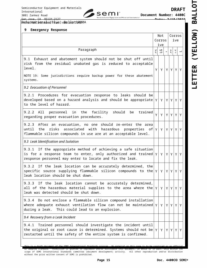
9.1 Exhaust and abatement system should not be shut off until risk from the residual unabated gas is reduced to acceptable level.
19: Some jurisdictions require backup power for these abatement systems.Y Y Y Y Y Y
9.2 Evacuation of Personnel
9.2.1 Procedures for evacuation response to leaks should be developed based on a hazard analysis and should be appropriate to the level of hazard. Y Y Y Y Y Y
9.2.2 All personnel in the facility should be trained regarding proper evacuation procedures. Y Y Y Y Y Y
9.2.3 After an evacuation, no one should re-enter the area until the risks associated with hazardous properties of flammable silicon compounds in use are at an acceptable level. Y Y Y Y Y Y
9.3 Leak Identification and Isolation
9.3.1 If the appropriate method of achieving a safe situation is for a response team to enter, only authorized and trained response personnel may enter to locate and fix the leak. Y Y Y Y Y Y
9.3.2 If the leak location can be accurately determined, the specific source supplying flammable silicon compounds to the leak location should be shut down. Y Y Y Y Y Y
9.3.3 If the leak location cannot be accurately determined, all of the hazardous material supplies to the area where the leak was detected should be shut down. Y Y Y Y Y Y
9.3.4 Do not enclose a flammable silicon compound installation where adequate exhaust ventilation flow can not be maintained during a leak. This could lead to an explosion. Y Y Y Y Y Y
9.4 Recovery from a Leak Incident
9.4.1 Trained personnel should investigate the incident until the original or root cause is determined. Systems should not be restarted until the safety of the entire system is confirmed. Y Y Y Y Y Y
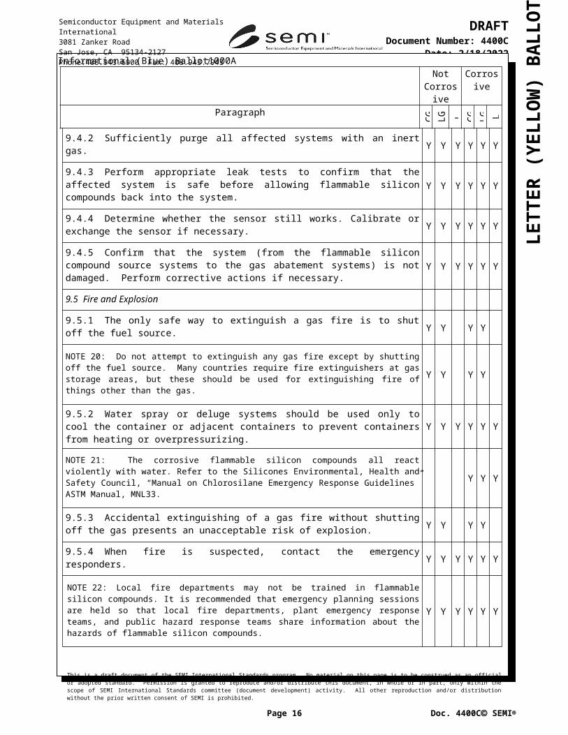
9.4.2 Sufficiently purge all affected systems with an inert gas. Y Y Y Y Y Y
9.4.3 Perform appropriate leak tests to confirm that the affected system is safe before allowing flammable silicon compounds back into the system. Y Y Y Y Y Y
9.4.4 Determine whether the sensor still works. Calibrate or exchange the sensor if necessary. Y Y Y Y Y Y
9.4.5 Confirm that the system (from the flammable silicon compound source systems to the gas abatement systems) is not damaged. Perform corrective actions if necessary. Y Y Y Y Y Y
9.5 Fire and Explosion
9.5.1 The only safe way to extinguish a gas fire is to shut off the fuel source. Y Y Y Y
20: Do not attempt to extinguish any gas fire except by shutting off the fuel source. Many countries require fire extinguishers at gas storage areas, but these should be used for extinguishing fire of things other than the gas.
Y Y Y Y
9.5.2 Water spray or deluge systems should be used only to cool the container or adjacent containers to prevent containers from heating or overpressurizing. Y Y Y Y Y Y
This is a draft document of the SEMI International Standards program. No material on this page is to be construed as an official or adopted standard. Permission is granted to reproduce and/or distribute this document, in whole or in part, only within the scope of SEMI International Standards committee (document development) activity. All other reproduction and/or distribution without the prior written consent of SEMI is prohibited.
Page 10 Doc. 4400C SEMI
Semiconductor Equipment and Materials International3081 Zanker RoadSan Jose, CA 95134-2127Phone:408.943.6900 Fax: 408.943.7943
DRAFTDocument Number: 4400C
Date: 5/6/2023

LETT
ER (Y
ELLO
W) B
ALL
OT
Informational (Blue) Ballot1000ANot
CorrosiveCorrosive
Paragraph
CG LG L CG LG L
21: The corrosive flammable silicon compounds all react violently with water. Refer to the Silicones Environmental, Health and Safety Council, “Manual on Chlorosilane Emergency Response Guidelines” ASTM Manual, MNL33.
Y Y Y
9.5.3 Accidental extinguishing of a gas fire without shutting off the gas presents an unacceptable risk of explosion. Y Y Y Y
9.5.4 When fire is suspected, contact the emergency responders. Y Y Y Y Y Y
22: Local fire departments may not be trained in flammable silicon compounds. It is recommended that emergency planning sessions are held so that local fire departments, plant emergency response teams, and public hazard response teams share information about the hazards of flammable silicon compounds.
Y Y Y Y Y Y
9.5.5 Only trained personnel should enter an area affected by a flammable silicon compound fire. Y Y Y Y Y Y
9.5.5.1 Trained responders to a fire event should be wearing appropriate protective equipment before entering the area. Y Y Y Y Y Y
9.5.5.2 After a fire event, check the installed fire detectors. Change the detectors if necessary. Y Y Y Y Y Y
This is a draft document of the SEMI International Standards program. No material on this page is to be construed as an official or adopted standard. Permission is granted to reproduce and/or distribute this document, in whole or in part, only within the scope of SEMI International Standards committee (document development) activity. All other reproduction and/or distribution without the prior written consent of SEMI is prohibited.
Page 11 Doc. 4400C SEMI
Semiconductor Equipment and Materials International3081 Zanker RoadSan Jose, CA 95134-2127Phone:408.943.6900 Fax: 408.943.7943
DRAFTDocument Number: 4400C
Date: 5/6/2023

LETT
ER (Y
ELLO
W) B
ALL
OT
Informational (Blue) Ballot1000A
10 Offline Storage FacilitiesNot
CorrosiveCorrosive
Paragraph
CG LG L CG LG L
10.1 General Considerations
10.1.1 Offline storage facility construction materials should be non-combustible and compatible with the hazards presented by flammable silicon compounds that are present. Y Y Y Y Y Y
23: For certain chemicals, it may be necessary to consider multiple hazards, such as in the case of dichlorosilane, which is both flammable and corrosive. Y Y Y Y Y Y
10.1.2 Flammable silicon compounds should be separated from other chemicals per SEMI S4. Y Y Y Y Y Y
10.1.3 The recommended storage temperature is lower than 40°C. Y Y Y Y Y Y
10.1.4 A water deluge or sprinkler system should be installed over storage area for flammable silicon compounds to cool the containers during a fire event and reduce the effect of impingement of flame from one container on another.
Y Y Y Y Y
EXCEPTION: Containers of volume of 1 liter or less are exempt from this criterion. Y Y Y Y Y
24: Sprinkler system over water-reactive liquid is dangerous. A medium expansion foam system is recommended for corrosive flammable silicon compound liquids. Y
10.1.5 Containers of flammable silicon compounds in storage should have their valve plugs securely tightened and their valve protective caps in-place. Y Y Y Y Y Y
10.1.6 Containers should be stored in an area adequately designed to protect the building from reasonably foreseeable incidents in the storage area. Y Y Y Y Y Y
10.1.7 If containers of flammable silicon compounds are stored in a structure independent of occupied buildings, mechanical or natural ventilation at a minimum of 0.005 meter/second (1cfm/square foot) should be provided for the structure in which the containers are stored.
Y Y Y Y Y Y
25: Refer to standards such as NFPA 318 or High Pressure Gas Safety Law for more details. Y Y Y Y Y Y
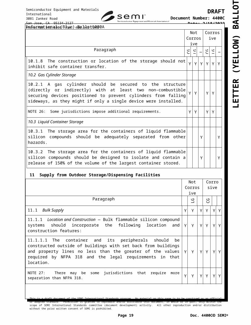
10.1.8 The construction or location of the storage should not inhibit safe container transfer. Y Y Y Y Y Y
10.2 Gas Cylinder Storage
10.2.1 A gas cylinder should be secured to the structure (directly or indirectly) with at least two non-combustible securing devices positioned to prevent cylinders from falling sideways, as they might if only a single device were installed.
Y Y Y Y
26: Some jurisdictions impose additional requirements. Y Y Y Y
10.3 Liquid Container Storage
10.3.1 The storage area for the containers of liquid flammable silicon compounds should be adequately separated from other hazards. Y Y
10.3.2 The storage area for the containers of liquid flammable silicon compounds should be designed to isolate and contain a release of 150% of the volume of the largest container stored. Y Y
This is a draft document of the SEMI International Standards program. No material on this page is to be construed as an official or adopted standard. Permission is granted to reproduce and/or distribute this document, in whole or in part, only within the scope of SEMI International Standards committee (document development) activity. All other reproduction and/or distribution without the prior written consent of SEMI is prohibited.
Page 12 Doc. 4400C SEMI
Semiconductor Equipment and Materials International3081 Zanker RoadSan Jose, CA 95134-2127Phone:408.943.6900 Fax: 408.943.7943
DRAFTDocument Number: 4400C
Date: 5/6/2023

LETT
ER (Y
ELLO
W) B
ALL
OT
Informational (Blue) Ballot1000A11 Supply from Outdoor Storage/Dispensing Facilities
Not Corrosive
Corrosive
Paragraph
CG LG L CG LG L
11.1 Bulk Supply Y Y Y Y Y Y
11.1.1 Location and Construction — Bulk flammable silicon compound systems should incorporate the following location and construction features: Y Y Y Y Y Y
11.1.1.1 The container and its peripherals should be constructed outside of buildings with set back from buildings and property lines no less than the greater of the values required by NFPA 318 and the legal requirements in that location.
Y Y Y Y Y Y
27: There may be some jurisdictions that require more separation than NFPA 318. Y Y Y Y Y Y
28: Additional protective barriers may be required to shield nearby structures or activities from potential flying objects. Y Y Y Y Y Y
29: CGA G-13 contains an example layout. Y
11.1.1.2 The storage area should have at least two exits. Y Y Y Y Y Y
11.1.1.3 A full risk assessment should be performed to determine if there are other risks with the location such as vehicular traffic and sabotage. Y Y Y Y Y Y
11.1.1.4 The storage configuration should be of open construction and have natural ventilation that does not allow for pocketing of flammable silicon compounds that could result in explosion.
Y Y Y Y Y Y
30:Enclosure is required in some country.
11.1.1.5 Bulk systems should be separated from each other and from the regulator station by 2-hour-rated firewalls. Y Y Y Y Y Y
11.1.2 Controls and Safeguards Y Y Y Y Y Y
11.1.2.1 Bulk systems should be equipped with the following controls and safeguards: Y Y Y Y Y Y
a) Excess flow protection, Y Y Y Yb) Secondary containment for spills, Y Yc) A manual shutdown valve at both the point of supply and the point of use and
dispensing, Y Y Y Y Y Y
d) Overpressure monitors with pressure relief and automatic gas shut off, Y Y Y Ye) A system to prevent overfilling for automated delivery systems, and Y Yf) Gas/chemical detection Y Y Y
31: Detection of byproducts between target gas/chemical and air is sometimes more important. For example, dichlorosilane (SiH2Cl2) reacts in moist air to form two molecules of HCl for each molecule of SIH2Cl2. Therefore, HCl is generated at twice the rate as the molar release rate of SiH 2Cl2. As stated in ¶ A1-5.2 of SEMI S6, both the hazards of SiH2Cl2 and of HCl must be considered, although the release rates should not be added, as a molecule of SiH2Cl2 ceases to exist upon creation of HCl from it.
Y Y Y
11.1.2.2 Access control should be provided to ensure entry is restricted to trained and authorized personnel. Y Y Y Y Y Y
This is a draft document of the SEMI International Standards program. No material on this page is to be construed as an official or adopted standard. Permission is granted to reproduce and/or distribute this document, in whole or in part, only within the scope of SEMI International Standards committee (document development) activity. All other reproduction and/or distribution without the prior written consent of SEMI is prohibited.
Page 13 Doc. 4400C SEMI
Semiconductor Equipment and Materials International3081 Zanker RoadSan Jose, CA 95134-2127Phone:408.943.6900 Fax: 408.943.7943
DRAFTDocument Number: 4400C
Date: 5/6/2023

LETT
ER (Y
ELLO
W) B
ALL
OT
Informational (Blue) Ballot1000ANot
CorrosiveCorrosive
Paragraph
CG LG L CG LG L
11.1.2.3 Workers from the gas supplier and trained site personnel should be the only persons authorized to work in bulk flammable silicon compound areas. Y Y Y Y Y Y
11.1.2.4 A flow limiting device should be placed in the outlet valve of the delivery manifold serving bulk source. The flow limiting device [for example, restricted flow orifice (RFO)] size used on the outlet valve should be as small as possible to meet combined process needs. See SEMI S5 for instructions as to how to choose the appropriate size flow limiting device.
Y Y Y Y
32: Combined process needs include the influences of the length of the delivery line. Y Y Y Y
11.2 Open Dispensing Racks for Cylinders
11.2.1 Open dispensing racks for silane should not be located in rooms inside of any building. Y
11.2.2 Exterior dispensing areas should be separated from structures in accordance with applicable standards, such as CGA G13. The dispensing area should be open on at least three sides with cylinders secured to noncombustible structures. Where a canopy is provided, the height should be a minimum of 3.7 m (12 ft). [NFPA318]
Y
33: CGA G-13 contains an example layout. Y
11.3 Manifolded Systems
34: Jurisdictions may impose additional requirements. Y Y Y Y Y Y
11.3.1 A system of controls regarding how many and which cylinders are on-line should be implemented. This includes how many cylinders can be connected in any given bundle as well as the capacity of the cylinders.
Y Y
11.3.2 Manifolded Systems should not be used for liquefied gas cylinders. Y Y
35: In a manifolded system, a difference of just a few degrees in temperature between cylinders can cause the gas in the warmer cylinder to travel into the cooler cylinder and condense as the product in that cylinder equilibrates. The risk increases with the temperature differential between the cylinders and when the cylinders are stored for long periods of time, as on a product reserve bank.
Y Y
11.3.3 Cylinders should be equipped with normally closed automatic pneumatic shutoff valves. Y Y
11.3.4 Cylinders should be equipped with restricted flow orifices. Y Y
36: The industry has moved almost exclusively to this condition. Y Y
11.4 Cylinder Pack Systems
37: For cylinder pack systems, a gas detection system may be required by some jurisdictions. The detection should close all cylinders ESOVs upon activation. Y Y
38:An example of the recommended arrangement in a cylinder gas supply system is shown in Appendix 1. Y Y Y Y Y Y
This is a draft document of the SEMI International Standards program. No material on this page is to be construed as an official or adopted standard. Permission is granted to reproduce and/or distribute this document, in whole or in part, only within the scope of SEMI International Standards committee (document development) activity. All other reproduction and/or distribution without the prior written consent of SEMI is prohibited.
Page 14 Doc. 4400C SEMI
Semiconductor Equipment and Materials International3081 Zanker RoadSan Jose, CA 95134-2127Phone:408.943.6900 Fax: 408.943.7943
DRAFTDocument Number: 4400C
Date: 5/6/2023

LETT
ER (Y
ELLO
W) B
ALL
OT
Informational (Blue) Ballot1000ANot
CorrosiveCorrosive
Paragraph
CG LG L CG LG L
11.4.1 If multiple cylinders are used in parallel for continuous supply during a cylinder replacement, an automated switching system should be employed for the system. Y Y Y Y Y Y
11.4.2 Flow limiting devices should be only as large as necessary to meet process flow requirements. Y Y Y Y
12 Supply from Indoor Storage/Dispensing FacilitiesNot
CorrosiveCorrosive
Paragraph
CG LG L CG LG L
12.1 Bulk supply systems should not be located indoors. Y Y Y Y Y
EXCEPTION: Non-corrosive liquid flammable silicon compound bulk supply systems may be located indoors. Y
12.2 Gaseous flammable silicon compounds should not be stored in locations below ground level. Y Y Y Y
12.3 Open dispensing cylinder racks for silane should not be located indoors. Y
12.4 Cylinder Systems Using Gas Cabinet
39: Liquid flammable silicon compounds may be supplied from cylinders. Y Y
12.4.1 Labeling — Labeling on Gas Cabinets should include the following information:1. Name of the process or equipment supplied by the cabinet2. Name of the flammable silicon compounds contained in the cabinet3. Name of the purge gas used
Y Y Y Y Y Y
12.4.2 Exhaust Ventilation
12.4.2.1 A forced exhaust system should be provided for cabinets. Air flow should be directed across potential leak points to prevent pocketing. Y Y Y Y Y Y
40: Recommendations for cabinet exhaust can be found in FM Global Property Loss prevention Sheet 7-7R. Y Y Y Y Y Y
12.4.2.2 The exhaust ventilation system for flammable silicon compounds should have the capability of treating a worst case leak. The treatment may be accomplished by either an abatement system or dilution of flammable silicon compounds to less than 25% of the lower flammable limit and less than 50% of IDLH.
Y Y Y Y Y Y
41: A worst case leak is typically a full-flow release rate from the largest cylinder installed through the flow limiting device at full cylinder pressure. Y Y Y Y
12.4.2.3 The exhaust ventilation system should be provided with automatic emergency source of backup power. Y Y Y Y Y Y
42: Jurisdictional requirements may define backup power. Y Y Y Y Y Y
This is a draft document of the SEMI International Standards program. No material on this page is to be construed as an official or adopted standard. Permission is granted to reproduce and/or distribute this document, in whole or in part, only within the scope of SEMI International Standards committee (document development) activity. All other reproduction and/or distribution without the prior written consent of SEMI is prohibited.
Page 15 Doc. 4400C SEMI
Semiconductor Equipment and Materials International3081 Zanker RoadSan Jose, CA 95134-2127Phone:408.943.6900 Fax: 408.943.7943
DRAFTDocument Number: 4400C
Date: 5/6/2023

LETT
ER (Y
ELLO
W) B
ALL
OT
Informational (Blue) Ballot1000ANot
CorrosiveCorrosive
Paragraph
CG LG L CG LG L
43: Many jurisdictions require sensors, detectors, and lighting fixtures all to be of electrical construction meeting hazardous location requirements [for example, not less than NFPA 70 (NEC) Class 1 Div. 2.] in rooms classified as flammable rooms.
Y Y Y Y Y Y
44: In some jurisdictions, the exhaust ventilation and abatement systems may not be required to operate continuously, provided when a leak is detected, the exhaust ventilation and abatement system be activated to abate the leak.
Y Y Y Y Y Y
12.4.2.4 Mechanical ventilation should be provided for the gas cabinet to keep the pressure inside the cabinet below that of the surrounding atmosphere. The effectiveness of the exhaust ventilation should be monitored.
Y Y Y Y Y Y
12.4.2.5 Vent lines of the high pressure side of the regulator of flammable silicon compound cylinders should be routed to an abatement system. The system should have the capability to abate the largest possible flow through the cylinder flow restrictor.
Y Y Y Y
45: It is recommended not to install regulator to liquefied gas which vapor pressure is less than 0.2 MPa (29 psi), such as dichlorosilane. [Dichlorosilane has a vapor pressure of 0.16 MPa (23.8 psi).]
Y Y
12.4.2.6 If there is no mechanical means of flow restriction (for example, RFO) at the cylinder outlet, excess flow switches should be provided upstream of the regulator, either in conjunction with high pressure process valves or on the pigtail immediately downstream of the cylinder valve. This is to limit the maximum flow of gas to the regulator.
Y Y Y Y
12.4.3 Single-cylinder flammable silicon compound cabinets are recommended. When there is more than one flammable silicon compound cylinder in a gas cabinet, and one or more cylinder is made of aluminum, each aluminum cylinder should be separated from other cylinders by a 6 mm (1/4 in.) thick steel plate.
Y
46: CGA G-13 contains an example of steel plate separators. Y Y Y Y
12.5 Liquid Container Cabinets
12.5.1 Total volume of liquid flammable silicon compound containers in a cabinet should not exceed 460 liters. Y Y
12.5.2 Cabinets for containers of liquid should meet either or both of ¶¶12.5.2.1 and 12.5.2.2. Y Y
12.5.2.1 Storage cabinets designed and constructed to limit the internal temperature at the center of the cabinet and 25 mm (1 in.) from the top of the cabinet to not more than 163°C (325°F), when subjected to a 10-minute fire test that simulates the fire exposure of the standard time–temperature curve specified in NFPA 251, or equivalent. All joints and seams remain tight and the door should remain securely closed during the test.
Y Y
12.5.2.2 Metal storage cabinets that satisfy all of the following:(a) The bottom, top, door, and sides of the cabinet should be at least 1.2 mm thick (No. 18 gauge sheet) steel and be double-walled, with 38 mm (11⁄2 in.) air space.(b) Joints shall be riveted, welded, or made tight by some equally effective means.(c) The door should be provided with a three-point latch arrangement, and the door sill should be raised above the bottom of the cabinet to retain a spill of 110% of the volume of the largest container.
Y Y
This is a draft document of the SEMI International Standards program. No material on this page is to be construed as an official or adopted standard. Permission is granted to reproduce and/or distribute this document, in whole or in part, only within the scope of SEMI International Standards committee (document development) activity. All other reproduction and/or distribution without the prior written consent of SEMI is prohibited.
Page 16 Doc. 4400C SEMI
Semiconductor Equipment and Materials International3081 Zanker RoadSan Jose, CA 95134-2127Phone:408.943.6900 Fax: 408.943.7943
DRAFTDocument Number: 4400C
Date: 5/6/2023
LETT
ER (Y
ELLO
W) B
ALL
OT
Informational (Blue) Ballot1000ANot
CorrosiveCorrosive
Paragraph
CG LG L CG LG L
12.5.3 Liquid Flammable Silicon Compound Containers Used in Liquid Container Cabinet Systems
47: Liquid flammable silicon compound containers typically have a valve with a diptube (liquid) and a valve to the top (vapor space) of the container. They are most commonly used in a cabinet as:
a bubbler where a carrier gas enters the diptube, is saturated with the flammable silicon compounds' vapor and exits from the vapor valve,
a bulk supply container (This is pressured with an inert gas through the vapor valve to push liquid through the diptube valve to fill a bubbler in the system.), or
a process container. (This is pressurized with an inert gas through the vapor valve to push liquid through the diptube to feed a vaporizer in the system.)
Y Y
12.5.3.1 The valves and outlets of the liquid container are typically oriented vertically. Liquid can be trapped and released when the connection is loosened. Procedures should ensure that any liquid remaining in the lines be pushed back into the container prior to the container being disconnected.
Y Y
48: Figure 1 shows an example of a typical liquid container configuration. Y Y
12.5.3.2 Care should be used to connect the proper side. The dip tube connection should be female and the vapor connection should be male. Y Y
49: SEMI F96 gives typical specification for port configuration of liquid containers. Y Y
12.5.3.3 Gas pressure to the containers should be regulated to a pressure below the MAWP of the container. Y Y
This is a draft document of the SEMI International Standards program. No material on this page is to be construed as an official or adopted standard. Permission is granted to reproduce and/or distribute this document, in whole or in part, only within the scope of SEMI International Standards committee (document development) activity. All other reproduction and/or distribution without the prior written consent of SEMI is prohibited.
Page 17 Doc. 4400C SEMI
Semiconductor Equipment and Materials International3081 Zanker RoadSan Jose, CA 95134-2127Phone:408.943.6900 Fax: 408.943.7943
DRAFTDocument Number: 4400C
Date: 5/6/2023
LETT
ER (Y
ELLO
W) B
ALL
OT
Informational (Blue) Ballot1000A
Figure 1Typical Liquid Container Configuration
This is a draft document of the SEMI International Standards program. No material on this page is to be construed as an official or adopted standard. Permission is granted to reproduce and/or distribute this document, in whole or in part, only within the scope of SEMI International Standards committee (document development) activity. All other reproduction and/or distribution without the prior written consent of SEMI is prohibited.
Page 18 Doc. 4400C SEMI
Semiconductor Equipment and Materials International3081 Zanker RoadSan Jose, CA 95134-2127Phone:408.943.6900 Fax: 408.943.7943
DRAFTDocument Number: 4400C
Date: 5/6/2023

LETT
ER (Y
ELLO
W) B
ALL
OT
Informational (Blue) Ballot1000A
Not Corrosive
Corrosive
Paragraph
CG LG L CG LG L
12.6 Cylinder Change Procedures - General
12.6.1 Cylinder replacement should be performed by two persons. Each should have received appropriate training to perform his tasks safely. Y Y Y Y
12.6.2 Appropriate personal protective equipment (PPE) should be worn during cylinder handling and changing. Y Y Y Y
12.6.3 To prevent accidental intake of air into the cylinder, the cylinder replacement should take place before the pressure drops to atmospheric pressure unless the cylinder is intended to operate below atmospheric pressure.
Y Y Y Y
12.6.3.1 At a certain minimum pressure, a warning should be provided to an attended location and the gas shut down. Y Y Y Y
EXCEPTION: This is not applicable to cylinders used under sub-atmospheric pressure from the beginning of use. Y Y Y Y
12.6.4 It is recommended to shut gas cylinder valves of all the gas cylinders, except purge gas cylinders, in the same cabinet that contains the cylinder to be exchanged. Y Y Y Y
EXCEPTION: When it is not practical to shut gas cylinder valves of all the gas cylinders in the same cylinder cabinet, special administrative controls such as temporary guarding should be considered to prevent damage to the in-use, pressurized lines which are in close proximity to the cylinder to be changed.
Y Y Y Y
50: When using an auto-switching system, there is potential for increased exposure when changing the empty cylinder when the other cylinder is still in use. It is recognized that the pressurized lines of the in-use cylinder may inadvertently bumped during the tasks of loosening and tightening fittings on the empty cylinder.
Y Y Y Y
51: Some monosilane cylinder cabinets have metal walls between cylinders. Y
12.6.5 Before opening the cabinet door to replace a cylinder, a visual inspection for powder deposits at potential leak points should be performed. If powder deposits are present, they are evidence of a leak in the system, and the door should not be opened. Only personnel specifically trained for handling such a situation should attempt to stop the leak and to fix the cause of the leak.
Y Y Y Y
52:It is recommended to have view port for cylinder cabinet or other type of secondary containment. A camera can be set out side of the secondary containment to observe the window to see if there is fire. Y Y Y Y
53:Deposits any color other than white indicates that reactive silicon compounds have been formed. Y Y Y Y Y Y
12.6.6 When cylinder is installed or exchanged, a well defined method of leak checking (See Appendix 4) should be performed to insure cylinder connection leak-tight integrity. Y Y Y Y Y
12.6.7 Auto-sequence Controllers Auto-sequence controllers are recommended whenever possible to reduce the potential for human error in cylinder change. Y Y Y Y
This is a draft document of the SEMI International Standards program. No material on this page is to be construed as an official or adopted standard. Permission is granted to reproduce and/or distribute this document, in whole or in part, only within the scope of SEMI International Standards committee (document development) activity. All other reproduction and/or distribution without the prior written consent of SEMI is prohibited.
Page 19 Doc. 4400C SEMI
Semiconductor Equipment and Materials International3081 Zanker RoadSan Jose, CA 95134-2127Phone:408.943.6900 Fax: 408.943.7943
DRAFTDocument Number: 4400C
Date: 5/6/2023

LETT
ER (Y
ELLO
W) B
ALL
OT
Informational (Blue) Ballot1000ANot
CorrosiveCorrosiv
eParagraph
CG LG L CG LG L
12.6.7.1 When an auto sequence controller is used, the leak test after replacement of the cylinder should be designed to monitor the pressures continuously within the purging supply system. Interrupted monitoring may not capture a pressure change that indicates ineffective purging.
Y Y Y Y
12.6.7.2 The design of automatic-sequence control systems for cylinder cabinets should incorporate the following features:a) Fault-tolerant design,b) The ability to perform a leak check of the container valve by measuring pressure rise in the
system, with the container valve closed, under the condition that the container has been connected and the purge gas eliminated,
c) Continuous pressure monitoring of the system during all purges and operating conditions, and
d) Written procedures for safe source container replacement including verification requirements for the leak testing and verification of the sensing system function.
Y Y Y Y
12.7 Step by Step Cylinder Change Procedure
12.7.1 Removal of the Used Cylinder
12.7.1.1 Shut off the cylinder valve. Y Y Y Y
12.7.1.2 Pump and purge the piping between the cylinder valve and the supply valve for the pre-determined cycles. Y Y Y Y
12.7.1.3 Before proceeding to cylinder removal step, confirm that there is no internal leakage of the cylinder valve. Y Y Y Y
12.7.1.4 Disconnect the cylinder at the cylinder valve outlet connection and secure the cylinder valve plug and the cylinder valve protective cap before removing the used cylinder from the cabinet.
Y Y Y Y
12.7.2 Installation of the New Cylinder
12.7.2.1 Carefully install the new cylinder in the cabinet and secure it in place. Remove the valve protective cap and the cylinder valve plug. Y Y Y Y
12.7.2.2 Remove the used gasket from the cylinder valve outlet connection. Place a new gasket at the gasket seat of the supply piping side of the cylinder valve outlet connection. Y Y Y Y
12.7.2.3 Connect the supply piping and the cylinder at the cylinder valve outlet connection and tighten the nut by hand. Confirm that there is no unusual resistance when tightening the nut. Y Y Y Y
12.7.2.4 After that, tighten the nut with the appropriate wrench to the proper torque.Y Y Y Y
12.7.3 Pressurization Test — The integrity of the cylinder valve outlet connection should be confirmed by the pressurization test in Appendix 4. Y Y Y Y
12.7.4 Inert Gas Purge — The line between the cylinder valve to the supply valve should be pumped and purged for pre-determined cycles to remove air components. Y Y Y Y
12.8 Transportation of Cylinders
This is a draft document of the SEMI International Standards program. No material on this page is to be construed as an official or adopted standard. Permission is granted to reproduce and/or distribute this document, in whole or in part, only within the scope of SEMI International Standards committee (document development) activity. All other reproduction and/or distribution without the prior written consent of SEMI is prohibited.
Page 20 Doc. 4400C SEMI
Semiconductor Equipment and Materials International3081 Zanker RoadSan Jose, CA 95134-2127Phone:408.943.6900 Fax: 408.943.7943
DRAFTDocument Number: 4400C
Date: 5/6/2023
LETT
ER (Y
ELLO
W) B
ALL
OT
Informational (Blue) Ballot1000ANot
CorrosiveCorrosiv
eParagraph
CG LG L CG LG L
12.8.1 Cylinder should be transported with the cylinder valve plug securely tightened and the cylinder valve protective cap in place. Y Y Y Y
12.8.2 Cylinders should be transported on appropriate carriages with adequate means for fixing the cylinders to the carriages. Y Y Y Y
12.9 Container Systems Using Liquid Cabinet
12.9.1 Liquid Container Change Procedures - General
12.9.1.1 Appropriate personal protective equipment (PPE) should be worn during liquid container handling and changing. Y Y
12.9.1.2 A means of determining the amount of liquid in the liquid container should be provided. Y Y
12.9.1.3 Before opening the cabinet door to replace a liquid container, a visual inspection for powder deposits at potential leak points should be performed. If powder deposits are present, they are evidence of a leak in the system, and the door should not be opened. Only personnel specifically trained for handling a such situation should attempt to stop the leak and to fix the cause of the leak.
Y Y
54: Deposits any color other than white indicates that reactive silicon compounds have been formed. Y Y
12.9.1.4 When liquid containers are installed or exchanged, a well defined method of leak checking (See Appendix 4) should be performed to insure container connection leak-tight integrity.
Y Y
12.9.1.5 Liquid container should be transported with the container valve plugs securely tightened and the container protective cover in place. Y Y
12.9.1.6 Liquid containers should be transported on appropriate carriages with adequate means for fixing the container to the carriage. Y Y
12.9.1.7 Liquid container replacement should be performed by two persons. Each should have received appropriate training to perform their tasks safely. Y Y
12.9.1.8 Auto-sequence Controllers - Auto-sequence controllers are recommended whenever possible to reduce the potential for human error in supply change-out. Y Y
12.9.1.9 When an auto-sequence controller is used, the leak test after replacement of the liquid container should be designed to monitor the pressures continuously within the purging supply system. Interrupted monitoring may not capture a pressure change that indicates ineffective purging.
Y Y
This is a draft document of the SEMI International Standards program. No material on this page is to be construed as an official or adopted standard. Permission is granted to reproduce and/or distribute this document, in whole or in part, only within the scope of SEMI International Standards committee (document development) activity. All other reproduction and/or distribution without the prior written consent of SEMI is prohibited.
Page 21 Doc. 4400C SEMI
Semiconductor Equipment and Materials International3081 Zanker RoadSan Jose, CA 95134-2127Phone:408.943.6900 Fax: 408.943.7943
DRAFTDocument Number: 4400C
Date: 5/6/2023

LETT
ER (Y
ELLO
W) B
ALL
OT
Informational (Blue) Ballot1000ANot
CorrosiveCorrosiv
eParagraph
CG LG L CG LG L
12.9.1.10 The design of automatic-sequence control systems for container cabinets should incorporate the following features:
1. Fault-tolerant design,
2. The ability to perform a leak check of the container valve by measuring pressure rise in the system, with the container valve closed, under the condition that the container has been connected and the purge gas eliminated,
3. Continuous pressure monitoring of the system during all purges and operating conditions, and
4. Written procedures for safe source container replacement including verification requirements for the leak testing and verification of the sensing system function.
Y Y
13 Indoor Distribution SystemNot Corrosive Corrosive
Paragraph
CG LG L CG LG L
13.1 General Considerations
13.1.1 To enable purging without venting into unsafe locations, a purge port should be installed at locations where sealed systems require purging. Each purge port should have a stop valve with a mechanical pressure gauge between the port and the valve and, if it is not connected to the purge gas, the purge port should be sealed with a cap or plug.
Y Y Y Y Y Y
13.1.2 Dead leg sections should be the smallest volume practical. Y Y Y Y Y Y
13.1.3 Flammable silicon compound delivery systems should be equipped with manual shutoff valves at both the point of dispensing and in the distribution line near the equipment gas panel.
Y Y Y Y Y Y
13.1.4 Flammable silicon compound delivery systems should be equipped with over-pressure monitors with pressure relief and automatic gas shutoff when pressure is detected above the designed limit.
Y Y Y Y
13.1.5 An excess flow control valve should be installed on every flammable silicon compounds' gas piping system as close as practical to the source. The excess flow control valve should be sized to deliver only as much gas as necessary to meet the process requirements.
Y Y Y Y
EXCEPTION: Excess flow control valves are not needed when the flow is limited by a mechanical device (for example, a flow restricting orifice) that cannot be set to a flow greater than the appropriate set point for an excess control valve in that location.
Y Y Y Y
55: A flow restricting orifice may become plugged, reducing the available flow, so the choice of which device to use requires careful consideration of the application, including the properties of the gas.
Y Y Y Y
13.2 Valve Manifold Boxes
13.2.1 Piping in valve manifold boxes should be purged with an inert gas by means that ensure complete purging of the piping and control system before the system is used to deliver flammable silicon compounds to the process and before the system is allowed to be opened for maintenance.
Y Y Y Y Y Y
This is a draft document of the SEMI International Standards program. No material on this page is to be construed as an official or adopted standard. Permission is granted to reproduce and/or distribute this document, in whole or in part, only within the scope of SEMI International Standards committee (document development) activity. All other reproduction and/or distribution without the prior written consent of SEMI is prohibited.
Page 22 Doc. 4400C SEMI
Semiconductor Equipment and Materials International3081 Zanker RoadSan Jose, CA 95134-2127Phone:408.943.6900 Fax: 408.943.7943
DRAFTDocument Number: 4400C
Date: 5/6/2023

LETT
ER (Y
ELLO
W) B
ALL
OT
Informational (Blue) Ballot1000ANot Corrosive Corrosive
Paragraph
CG LG L CG LG L
56: Recommended locations of valve manifold branch purging points are given in CGA G-13. Y
13.2.2 Valve manifold boxes should be provided with gas monitoring. Activation of the gas monitoring system should shut down the source of flammable silicon compounds. Y Y Y Y Y Y
13.2.3 Valve manifold boxes should be provided with fire detection. Activation of the fire detection system should shut down the source of flammable silicon compounds. Y Y Y Y Y Y
13.3 Piping and Components
13.3.1 Piping of indoor distribution systems should meet the following criteria in addition to general criteria described in Appendix 3. Y Y Y Y Y Y
13.3.1.1 Connection of piping should be welded or contained within an exhausted enclosure. Y Y Y Y Y Y
13.3.1.2 Piping should be labeled with the name of gas or liquid and flow direction. Y Y Y Y Y Y
13.3.1.3 If the piping diverges into two or more lines, each line should be provided with a shut off valve. Y Y Y Y Y Y
57: Some jurisdictions require both manual and automatic shut off valves. Y Y Y Y Y Y
13.3.1.4 A shutoff valve for each branch should be provided as close as is practical to where the branch begins. Y Y Y Y Y Y
58: The purpose of having these valves is to enable cycle purging of each line. Y Y Y Y Y Y
13.3.1.4.1 These shut off valves should be provided within an exhausted enclosure. Y
59: Exhausted enclosures are required for all valves on monosilane or highly toxic gas piping in CGA G13 and NFPA 318 respectively. Y
13.3.1.4.2 The enclosure should be monitored with detectors for the flammable silicon compounds present. Y Y Y Y Y Y
13.3.1.5 The ventilated enclosures should have exhaust ventilation monitoring per SEMI S2. Y Y Y Y Y Y
13.3.1.6 The piping of oxidizer gases should be isolated from the piping of flammable silicon compound gases. The isolation should also be applied to flammable silicon compound gas purge lines.
Y Y Y Y Y Y
13.3.2 Coaxial Piping
60: See Appendix 3, A3-3 about coaxial piping. Y Y Y Y
13.3.3 Valves — The state of a valve (open or closed) should be indicated through display or on the valve itself. The supplier should provide the user with reliability data for repeated operations, and the user should replace or service the valve, as directed by the valve manufacturer, within its expected lifetime.
Y Y Y Y Y Y
This is a draft document of the SEMI International Standards program. No material on this page is to be construed as an official or adopted standard. Permission is granted to reproduce and/or distribute this document, in whole or in part, only within the scope of SEMI International Standards committee (document development) activity. All other reproduction and/or distribution without the prior written consent of SEMI is prohibited.
Page 23 Doc. 4400C SEMI
Semiconductor Equipment and Materials International3081 Zanker RoadSan Jose, CA 95134-2127Phone:408.943.6900 Fax: 408.943.7943
DRAFTDocument Number: 4400C
Date: 5/6/2023

LETT
ER (Y
ELLO
W) B
ALL
OT
Informational (Blue) Ballot1000ANot Corrosive Corrosive
Paragraph
CG LG L CG LG L
13.3.4 Heaters and Heat Insulation Materials — External heating of piping and regulators may be required in outside locations or long distance lines to prevent re-liquification. In such cases, the following should be considered:
Y Y Y Y
13.3.4.1 If electrical resistance heating is used with insulation, the insulation should be visually inspected periodically for degradation or exposed wiring to avoid electrical arcing and damage to the piping.
Y Y Y Y
13.3.4.2 Electrical resistance piping heating systems should not be placed in wet areas because of the increased possibility of damage from corrosion. Y Y Y Y
13.3.4.3 Electrical resistance piping heating systems should be monitored. Monitors should alarm in the event of over temperature, an open circuit, earth leakage, or a short circuit and should shut off the heater power supply and gas supply.
Y Y Y Y
61: Increased earth leakage indicates degradation of the heater insulating material. Y Y Y Y
62: Gas supply shutdown may be required by some jurisdictions. Y Y Y Y
63: Heaters must conform to jurisdictional requirements for the device type. Y Y Y Y
This is a draft document of the SEMI International Standards program. No material on this page is to be construed as an official or adopted standard. Permission is granted to reproduce and/or distribute this document, in whole or in part, only within the scope of SEMI International Standards committee (document development) activity. All other reproduction and/or distribution without the prior written consent of SEMI is prohibited.
Page 24 Doc. 4400C SEMI
Semiconductor Equipment and Materials International3081 Zanker RoadSan Jose, CA 95134-2127Phone:408.943.6900 Fax: 408.943.7943
DRAFTDocument Number: 4400C
Date: 5/6/2023

LETT
ER (Y
ELLO
W) B
ALL
OT
Informational (Blue) Ballot1000A
14 Equipment Intended to Use Flammable Silicon Compounds14.1 Materials of Construction — Structural components of the equipment and components used for support of the equipment that can contact flammable silicon compounds under normal or reasonable foreseeable single point failure conditions should not be made of combustible materials (as defined in SEMI S2).
14.2 Design
14.2.1 Piping for flammable silicon compounds between equipment gas panel and process chambers should have secondary containment if the gas in the piping is above atmospheric pressure and the piping has one or more mechanical joints outside of exhausted and leak-monitored enclosures.
64: Secondary containment, including coaxial piping, within process equipment is not usually necessary if inside the primary containment is always kept below atmospheric pressure.
14.2.2 Safe State Equipment should be designed so that detection of a flammable silicon compound release by a detection system integral to the equipment, or part of the facility, immediately brings the equipment into a condition in which the equipment does not present any unacceptable risk to itself or to personnel. This condition includes not allowing hazardous production chemicals to flow. An acceptable condition is defined by the designer of the equipment and is based on the hazards in the design. Shutdown of the equipment may be appropriate.
65:If equipment is not provided with an integral detection system, then an interface (input) port connection that initiates equipment safe state can meet this requirement.
14.2.3 Process vacuum pumps for chambers in which flammable silicon compounds are used should be maintained and monitored for their ability to remove potentially hazardous flammable silicon compounds safely from equipment.
14.2.4 Equipment should be designed to shut off supply of flammable silicon compounds as well as of any other flammable gases and liquids upon activation of the fire detection system for the equipment.
66:Shutting off flammable silicon compound supply is the only safe method of extinguishing gas fires involving the substances.
14.2.5 Equipment should be capable of performing a purge/vacuum sequence to remove flammable silicon compounds from, and to reduce their volatile byproducts in, the process chamber so that risks associated with reaction between atmosphere and flammable silicon compounds or reactive byproducts are at an acceptable level before service or maintenance.
14.2.5.1 The minimum number of purge/vacuum cycles should be decided based on the results of tests that evaluate the effectiveness of such cycles.
14.2.5.2 The equipment supplier should specify the minimum number of cycles in the documentation provided to the user for each baseline process as defined by the supplier.
14.2.5.3 If adjustable, this minimum number of cycles should be controlled in such a way that only maintenance and service personnel have access to the means of changing the cycle count. The supplier should provide information in the user documentation about possible consequences of reducing the number of the cycles.
14.2.5.4 The equipment supplier should provide information in the user documentation with the minimum allowable number of cycles user may set for the user’s own processes. If the minimum allowable number of cycles vary with the process condition range (e.g., flowrate range of flammable silicon compounds, composition range of co-flown chemicals, etc.), the minimum allowable number of cycles should be provided for each process condition range.
14.2.6 If equipment is designed to flow any flammable silicon compounds with oxidizer gases with flammable silicon compounds to a chamber simultaneously, the flows should be controlled so that concentrations and pressures of those gases do not pose unacceptable risks.
14.2.7 The equipment should be designed so that, if gas remains from the preceding process step, the equipment will not initiate the next process step if mixing gas from the next process step with the gas that remains from the preceding process step can pose unacceptable risks.
This is a draft document of the SEMI International Standards program. No material on this page is to be construed as an official or adopted standard. Permission is granted to reproduce and/or distribute this document, in whole or in part, only within the scope of SEMI International Standards committee (document development) activity. All other reproduction and/or distribution without the prior written consent of SEMI is prohibited.
Page 25 Doc. 4400C SEMI
Semiconductor Equipment and Materials International3081 Zanker RoadSan Jose, CA 95134-2127Phone:408.943.6900 Fax: 408.943.7943
DRAFTDocument Number: 4400C
Date: 5/6/2023

LETT
ER (Y
ELLO
W) B
ALL
OT
Informational (Blue) Ballot1000A14.2.8 Flammable silicon compounds and oxidizer gases should have separate piping up to the point where gas flow can be automatically shut off by the equipment itself upon detection of unsafe gas condition (e.g., high pressure in process chamber) downstream of that point.
14.2.9 No single component failure should allow flammable silicon compounds and oxidizer gases to form a mixture, in manifolds or other areas, at masses, pressures and concentrations that would pose unacceptable risks.
14.3 Construction
14.3.1 Equipment interface points for the facilities gas supply piping should be designed with seismic bracing as needed to achieve the seismic protection detailed in SEMI S2.
14.3.2 The external forces on the bending points should be minimized by use of reverse bending or other methods.
14.3.3 Dead leg sections (internal piping which can trap gases) should be the smallest volume practical.
14.3.4 Process Chambers
14.3.4.1 Chambers intended for processes using flammable silicon compounds should be evaluated for their ability to control risks associated with reasonably foreseeable unsafe condition such as acute pressure rise resulted from reasonably foreseeable single point failures or misuse.
14.3.4.2 Process chambers using flammable silicon compounds should be provided with safety interlocks between chamber pressure and gas supply that prevents chamber pressure from increasing above the designed range.
14.3.4.3 Viewing Ports
14.3.4.3.1 If viewing ports are used they should be designed to withstand the maximum pressure that could result from a reasonably foreseeable single-point failure, or be provided with guard to capture any flying debris before it affects personnel or other equipment.
14.3.4.3.2 If viewing ports are intended to be user replaceable, the user documentation should specify the part and the change procedure and warn the user of the possible consequences of using non-authentic parts.
14.3.5 Enclosures
14.3.5.1 If an enclosure is required to contain hazardous gas mixture in the event of chamber rupture, the enclosure should be ventilated and evaluated per SEMI S2 and SEMI S6.
14.3.5.2 If the chamber rupture protection is an enclosure, all the removable enclosure panels or access doors should be interlocked to prevent process initiation or continuance if the enclosure is open.
14.3.6 The results of the tests specified in SEMI S6, should indicate that ambient concentration of flammable silicon mixture is controlled within the level specified in SEMI S2 during maintenance activities.
14.4 Vacuum Pump Systems
14.4.1 Materials of construction for vacuum pumps that are exposed to the gas stream should be compatible with the gas stream.
14.4.2 Vacuum pumps that are exposed to the gas stream should be dry type or, if a lubricated pump is to be used, only inert (non-hydrocarbon) oil should be used.
14.4.3 Purge gases for vacuum pumps should be inert. The flow rate of the purge gas should be within the range specified by the pump manufacturers for the condition the pump to be used.
14.4.4 If inert gas is added at the pump outlet for dilution purpose, the sum of purge gas and gas introduced for dilution should be sufficient to dilute the flammable silicon compounds' concentration in the piping between vacuum pump outlet and the abatement system below the minimum concentration in the diluent that can form an ignitable mixture with air.
EXCEPTION: If the intent is to treat the exhaust by combustion, a lesser amount of inert gas may be added, as long as the risk of fire is not unacceptable.
This is a draft document of the SEMI International Standards program. No material on this page is to be construed as an official or adopted standard. Permission is granted to reproduce and/or distribute this document, in whole or in part, only within the scope of SEMI International Standards committee (document development) activity. All other reproduction and/or distribution without the prior written consent of SEMI is prohibited.
Page 26 Doc. 4400C SEMI
Semiconductor Equipment and Materials International3081 Zanker RoadSan Jose, CA 95134-2127Phone:408.943.6900 Fax: 408.943.7943
DRAFTDocument Number: 4400C
Date: 5/6/2023

LETT
ER (Y
ELLO
W) B
ALL
OT
Informational (Blue) Ballot1000A67:Adding inert gas as described in Paragraph 14.4.4 can decrease the efficiency of exhaust treatment systems that use combustion. There are other ways to mitigate the fire risk, including the management of pressure in that piping and double containment.
68: If positive pressure is used to prevent backflows, then a additional pressure piping code requirements may need to be satisfied.
69: More purge gas flow may be necessary if other flammable gases are used with flammable silicon compounds.
14.4.5 The flow rate of purge gas flow should be interlocked to shut off the supply of flammable silicon compounds if the purge gas flow drops below the amount needed to insure adequate dilution.
14.5 Protection
14.5.1 Fire Detection and Suppression — Use the results of the risk assessment described in SEMI S14 to determine the need for fire detection and suppression.
14.5.2 As for any other safety design consideration aspect of process equipment, SEMI S2 provides criteria for assessing and managing safety risks.
14.6 Exhaust Ventilation that may be Necessary for the Equipment — Exhaust ventilation should be provided for the applicable part of equipment where failure of primary containment of flammable silicon compounds is reasonably foreseeable. Such parts include equipment gas panel enclosures and process gas pump enclosures.
14.6.1 Enclosures should be designed to minimize collection of flammable silicon compounds into pockets.
14.6.2 Mixing of flammable silicon compounds and oxidizer gases within the primary exhaust piping should be avoided.
14.6.3 Mixing of flammable silicon compounds and oxidizer gases within the secondary containment enclosures (and the secondary exhaust ducts from those enclosures) should be avoided if they can react each other under normal operating conditions or reasonably foreseeable fault conditions.
70: In addition to mixing two reactive process chemicals, it is noted that any pressurized pyrophoric gas and air also make an ignitable mixture, thus, air should be also be prevented from entering exhaust piping if pyrophoric gas is above LFL.
14.6.4 SEMI S6 should be used to design exhaust ventilation of enclosures.
14.7 Information on Exhaust Ventilation and Flammable Silicon Compound Effluents
14.7.1 The equipment supplier should provide exhaust ventilation information to the user. The information should be based on the baseline process and should include:
the chemicals and their composition,
the hazards expected if duct is open to air during the maintenance,
recommended maintenance procedures when the equipment exhaust ventilation is connected to a point-of-use gas abatement system,
recommended duct size and flow volumes, and
information on potential maintenance issues associated with the process (such as silicate deposits and reactive by-product generation).
71: An example of anticipated hazards created by exposing the duct to atmosphere is production of unstable polymer such as highly reactive types of polysiloxane.
14.7.2 The equipment supplier should provide flammable silicon compound effluent information to the user. The information should be based on the baseline process and should include:
the chemicals and their composition,
compatibility requirements and type of connection expected at the outlet of the vacuum pump,
the hazards expected if duct is open to air during the maintenance,
This is a draft document of the SEMI International Standards program. No material on this page is to be construed as an official or adopted standard. Permission is granted to reproduce and/or distribute this document, in whole or in part, only within the scope of SEMI International Standards committee (document development) activity. All other reproduction and/or distribution without the prior written consent of SEMI is prohibited.
Page 27 Doc. 4400C SEMI
Semiconductor Equipment and Materials International3081 Zanker RoadSan Jose, CA 95134-2127Phone:408.943.6900 Fax: 408.943.7943
DRAFTDocument Number: 4400C
Date: 5/6/2023

LETT
ER (Y
ELLO
W) B
ALL
OT
Informational (Blue) Ballot1000A recommended maintenance procedures when the equipment flammable silicon compound effluent stream is
connected to a point-of-use gas abatement system,
recommended piping size and flow volumes,
information on potential maintenance issues associated with the process (such as silicate deposits and reactive by-product generation),
maximum distance from the reaction chamber to the vacuum pump, and
maximum distance from the pump to the facility connection or the point-of-use abatement.
14.7.3 The need to route the flammable silicon compound effluents to the proper gas abatement system may require consideration of separate pump systems for oxidizer gases.
14.8 Other Information
14.8.1 Manuals, as defined in SEMI S13, should include information and training requirement on flammable silicon compounds, their hazards, and recommended protective measures.
14.8.2 Hazard alert labels should be designed in conformance with SEMI S1. Where such labels are to be placed should be decided in accordance with SEMI S2.
This is a draft document of the SEMI International Standards program. No material on this page is to be construed as an official or adopted standard. Permission is granted to reproduce and/or distribute this document, in whole or in part, only within the scope of SEMI International Standards committee (document development) activity. All other reproduction and/or distribution without the prior written consent of SEMI is prohibited.
Page 28 Doc. 4400C SEMI
Semiconductor Equipment and Materials International3081 Zanker RoadSan Jose, CA 95134-2127Phone:408.943.6900 Fax: 408.943.7943
DRAFTDocument Number: 4400C
Date: 5/6/2023

LETT
ER (Y
ELLO
W) B
ALL
OT
Informational (Blue) Ballot1000A
15 Exhaust Ventilation, Flammable Silicon Compound Effluent, and Abatement SystemsNot
CorrosiveCorrosive
Paragraph
CG LG L CG LG L
15.1 Design of Flammable Silicon Compound Effluent Systems (from Pump to the Inlet of Abatement System)
15.1.1 Materials of Construction
15.1.1.1 Materials for piping containing flammable silicon compound effluents should be compatible with the effluents including byproducts and should provide protection from heat and reactions, which may be present downstream of the reaction chamber.
Y Y Y Y Y Y
15.1.1.2 No combustible joint compound (including adhesive or tape) should be used to seal joints. Y Y Y Y Y Y
15.1.1.3 Flammable silicon compound effluent piping should withstand the maximum potential pressure generated by the reaction of the of flammable silicon compound effluents in a reasonably foreseeable worst case, single-point failure of the process equipment.
Y Y Y Y Y Y
15.1.1.4 Metal-gasket face-seal fittings should be used wherever possible. Compression fittings lead to increased risk of leaks, especially when subjected to expansion and contraction caused by internally burning and extinguishing of flammable silicon compounds.
Y Y Y Y Y Y
15.1.1.5 Mechanical fittings that can be exposed to above atmospheric pressure at normal operation condition or in reasonable foreseeable failure should be enclosed in exhausted enclosures.
Y Y Y Y Y Y
72: Leaking can be caused by the result of assembly and disassembly during pump and treatment system maintenance. Y Y Y Y Y Y
15.1.2 Ports for chemical sampling should be provided in order to enable inspection of deposits and sampling of gas composition and concentration in the piping. Each port should have a stop valve and, if not connected to a sampling device, should be sealed with a cap or plug.
Y Y Y Y Y Y
15.1.3 The system should be designed to have a means of determining if the piping is blocked. View ports should be periodically cleaned to provide for adequate viewing capability. If effluents including byproducts are corrosive, these ports should be compatible with the hazards presented.
Y Y Y Y Y Y
15.2 Flammable Silicon Compound Effluent and Exhaust Ventilation System Maintenance
15.2.1 Prior to performing maintenance, maintenance personnel should inspect piping and ducts to examine if there is any liquid or solid material accumulated. Y Y Y Y Y Y
73: Liquid or solid indicates build-up of reaction products. Such reaction products are often very unstable and very reactive to atmosphere. Y Y Y Y Y Y
15.2.1.1 This inspection should be performed periodically to insure gas composition and quantities have not generated new hazards and to characterize deposits and ensure they are being removed.
Y Y Y Y Y Y
This is a draft document of the SEMI International Standards program. No material on this page is to be construed as an official or adopted standard. Permission is granted to reproduce and/or distribute this document, in whole or in part, only within the scope of SEMI International Standards committee (document development) activity. All other reproduction and/or distribution without the prior written consent of SEMI is prohibited.
Page 29 Doc. 4400C SEMI
Semiconductor Equipment and Materials International3081 Zanker RoadSan Jose, CA 95134-2127Phone:408.943.6900 Fax: 408.943.7943
DRAFTDocument Number: 4400C
Date: 5/6/2023

LETT
ER (Y
ELLO
W) B
ALL
OT
Informational (Blue) Ballot1000ANot
CorrosiveCorrosive
Paragraph
CG LG L CG LG L
15.2.1.2 If the investigation indicates the deposit is reactive or unstable, a procedure to stabilize or neutralize the deposit before opening the piping or duct to air should be implemented.
Y Y Y Y Y Y
15.2.2 Due to the hazards associated with deposits formed from flammable silicon compound effluents, only maintenance workers trained to handle the potential for reactions, small fires or explosions should be allowed to perform maintenance on flammable silicon compound effluent piping and exhaust ducts.
Y Y Y Y Y Y
15.2.2.1 Equipment suppliers should provide, in the maintenance manuals, stabilizing or neutralizing procedures for substances likely to be accumulated in the exhaust lines. Y Y Y Y Y Y
15.2.2.2 Equipment suppliers should also notify users that stabilizing or neutralizing procedures provided in the maintenance manuals might not work if the exhaust lines are connected to other process equipment using flammable silicon compounds.
Y Y Y Y Y Y
15.3 Abatement Systems
15.3.1 Selection of Abatement System
15.3.1.1 Refer to SEMI F5 for techniques and information to determine the appropriate abatement system. Y Y Y Y Y Y
15.3.1.2 An abatement system should be selected with consideration for both equipment and facilities. Y Y Y Y Y Y
15.3.1.3 The user should determine the composition, concentration, amount per minute and possible phases (solid, liquid or gas) of all chemicals to be treated, before requesting quotations on abatement systems. This information is very important to selecting or designing an appropriate abatement system.
Y Y Y Y Y Y
15.3.1.4 The user should also provide name and maximum flow rate of all the gases and chemicals that can flow into the abatement equipment that do not need to be treated. The information should be provided for normal operation and all reasonable foreseeable failures.
Y Y Y Y Y Y
15.3.1.5 The abatement system manufacturer should provide the user with information about necessity of inert gas dilution or having chemicals having negative effects on abatement process bypass the abatement system.
Y Y Y Y Y Y
15.3.1.6 The abatement system manufacturer should provide the user with recommended maintenance procedures, in written form, considering the characteristics of flammable silicon compound effluents that can be treated by the gas abatement system, even if the manufacturer maintains the system. Maintenance workers should be trained as specified by the manufacturer.
Y Y Y Y Y Y
15.3.2 Interlocks
15.3.2.1 Interlocks should be provided at appropriate locations to stop the flow of process effluent to the abatement system during maintenance and service. Y Y Y Y Y Y
15.3.2.2 Interlocks should be provided at appropriate locations to stop the flow of process effluent to the abatement system when abnormal status of an abatement system is detected. Y Y Y Y Y Y
This is a draft document of the SEMI International Standards program. No material on this page is to be construed as an official or adopted standard. Permission is granted to reproduce and/or distribute this document, in whole or in part, only within the scope of SEMI International Standards committee (document development) activity. All other reproduction and/or distribution without the prior written consent of SEMI is prohibited.
Page 30 Doc. 4400C SEMI
Semiconductor Equipment and Materials International3081 Zanker RoadSan Jose, CA 95134-2127Phone:408.943.6900 Fax: 408.943.7943
DRAFTDocument Number: 4400C
Date: 5/6/2023

LETT
ER (Y
ELLO
W) B
ALL
OT
Informational (Blue) Ballot1000ANot
CorrosiveCorrosive
Paragraph
CG LG L CG LG L
15.3.2.3 Some abatement systems need enclosures. Such enclosures should be monitored for leaks. Upon leak detection, an alarm should be activated and gas and the flow of effluent to the abatement system should be shut off.
Y Y Y Y Y Y
74: Shutting off of the gas and chemicals at the source may be deemed necessary depending on over all configuration of facility including the process equipment and the abatement system. Y Y Y Y Y Y
15.3.3 Absorbent Systems
15.3.3.1 Gas leak detection and breakthrough detection should be provided for absorbent systems. To ensure that each gas abatement system functions properly, it should have gas detection and alarm system that detects breakthrough of absorbent. The location of sample points should be appropriate to detect breakthrough of the absorbent according to the abatement system instructions.
Y Y Y Y Y Y
15.3.3.2 When breakthrough is detected, the gas and chemical supplies to the equipment connected to the failed abatement system should be shut off. Absorbent in the consumed abatement system should be replaced immediately. Alternatively, a switching system can be employed to switch to a back-up absorbent bed or redundant abatement system.
Y Y Y Y Y Y
15.3.4 Combustion Systems — In a combustion-type abatement system, a flame detector, an airflow rate sensor, an exhaust temperature monitor and a gas/chemical concentration monitor at the outlet should be used for detecting abnormal status of those parameters.
Y Y Y Y Y Y
15.3.5 Combination with Wet-type Abatement Systems — If a wet-type abatement system is used downstream of an adsorbent or combustion type abatement system, it should be designed to prevent reverse flow of water into the upstream systems
Y Y Y Y Y Y
15.3.5.1 Monitoring to determine any abnormal operating condition of the wet-type system should be provided. Y Y Y Y Y Y
15.3.5.2 The system should be equipped with a water leak sensor. Y Y Y Y Y Y
15.3.6 Operation
15.3.6.1 Adequate performance of the abatement system should be ensured at all times. Y Y Y Y Y Y
75: Constant monitoring of the concentration at the outlet may be required by some jurisdictions. The source gas may also have to be shut down if the emissions reach the maximum allowable amount.
Y Y Y Y Y Y
76: It may not be necessary for abatement systems to be constantly “on-line” in some jurisdictions when gas is “stored” and not “dispensed”. In such a situation, the abatement system may be allowed to start when a leak is detected.
Y Y Y Y Y Y
15.3.6.2 When the abatement system has been stopped by malfunction, it should not automatically restart. Y Y Y Y Y Y
This is a draft document of the SEMI International Standards program. No material on this page is to be construed as an official or adopted standard. Permission is granted to reproduce and/or distribute this document, in whole or in part, only within the scope of SEMI International Standards committee (document development) activity. All other reproduction and/or distribution without the prior written consent of SEMI is prohibited.
Page 31 Doc. 4400C SEMI
Semiconductor Equipment and Materials International3081 Zanker RoadSan Jose, CA 95134-2127Phone:408.943.6900 Fax: 408.943.7943
DRAFTDocument Number: 4400C
Date: 5/6/2023

LETT
ER (Y
ELLO
W) B
ALL
OT
Informational (Blue) Ballot1000A
APPENDIX 1System Configuration – Cylinder SourcesNOTICE: The material in this appendix is an official part of SEMI S18 and was approved by full letter ballot procedures on (date of approval).
A1-1 Indoor Cylinder InstallationsA1-1.1 Equipment for indoor installations consists of gas cabinet, process gas panel, and purge gas panel. VMBs are used for multiple use points.
Figure A1-1 Typical Purge Gas Panel
Figure A1-2 Typical Process Gas Panel
This is a draft document of the SEMI International Standards program. No material on this page is to be construed as an official or adopted standard. Permission is granted to reproduce and/or distribute this document, in whole or in part, only within the scope of SEMI International Standards committee (document development) activity. All other reproduction and/or distribution without the prior written consent of SEMI is prohibited.
Page 32 Doc. 4400C SEMI
s
Semiconductor Equipment and Materials International3081 Zanker RoadSan Jose, CA 95134-2127Phone:408.943.6900 Fax: 408.943.7943
DRAFTDocument Number: 4400C
Date: 5/6/2023

LETT
ER (Y
ELLO
W) B
ALL
OT
Informational (Blue) Ballot1000A
Figure A1-3 Typical VMB Schematic
This is a draft document of the SEMI International Standards program. No material on this page is to be construed as an official or adopted standard. Permission is granted to reproduce and/or distribute this document, in whole or in part, only within the scope of SEMI International Standards committee (document development) activity. All other reproduction and/or distribution without the prior written consent of SEMI is prohibited.
Page 33 Doc. 4400C SEMI
Semiconductor Equipment and Materials International3081 Zanker RoadSan Jose, CA 95134-2127Phone:408.943.6900 Fax: 408.943.7943
DRAFTDocument Number: 4400C
Date: 5/6/2023

LETT
ER (Y
ELLO
W) B
ALL
OT
Informational (Blue) Ballot1000A
APPENDIX 2System Configuration – Bulk SourcesNOTICE: The material in this appendix is an official part of SEMI S18 and was approved by full letter ballot procedures on (date of approval).
Figure A2-1 Typical Monosilane Bulk System Flow
77: Separation and setback considerations for flammable silicon compound storage and dispensing areas must be in accordance with jurisdictional requirements.
This is a draft document of the SEMI International Standards program. No material on this page is to be construed as an official or adopted standard. Permission is granted to reproduce and/or distribute this document, in whole or in part, only within the scope of SEMI International Standards committee (document development) activity. All other reproduction and/or distribution without the prior written consent of SEMI is prohibited.
Page 34 Doc. 4400C SEMI
Semiconductor Equipment and Materials International3081 Zanker RoadSan Jose, CA 95134-2127Phone:408.943.6900 Fax: 408.943.7943
DRAFTDocument Number: 4400C
Date: 5/6/2023

LETT
ER (Y
ELLO
W) B
ALL
OT
Informational (Blue) Ballot1000A
APPENDIX 3Piping and Flow Components
NOTICE: The material in this appendix is an official part of SEMI S18 and was approved by full letter ballot procedures on (date of approval).
Not Corrosive
Corrosive
Paragraph
CG LG L CG LG L
A3-1 Materials
A3-1.1 Materials selected for use with corrosive and flammable silicon compounds should be suitable for maintaining structural integrity and provide adequate protection from corrosion. Y Y Y
78: Materials such as SUS304, SUS316, SUS316L, Monel, Hastelloy or XM-27 may be considered. Y Y Y
A3-1.2 Piping for liquid flammable silicon compounds should be conductive. Y Y
79: In most cases, the liquid silicon compounds are transferred as a liquid to process containers, such as bubblers. If nonconductive piping (for example, PTFE flexible lines with stainless steel metal braid) are used, the large static charge can discharge through the PTFE, puncturing it.
Y Y
A3-1.3 Plastic gaskets or O-rings used for corrosive and flammable silicon compounds should be made of chemically stable and heat-resistive materials. Y Y Y Y Y Y
80: Some jurisdictions do not permit the use of PTFE for this purpose, although it is recommended by other jurisdictions. Y Y Y Y Y Y
81: Refer to § 13 for criteria on heating insulation. Y Y Y Y Y Y
A3-2 Flow Components
A3-2.1 Flow components should be selected so as not to increase risk under normal conditions or reasonably foreseeable single point failure conditions. Y Y Y Y Y Y
82: Some regions require components to be approved. Y Y Y Y Y Y
A3-2.2 When cylinder connection gaskets are used they should be single-use metal-surface compression gaskets (unless incompatible) that do not provide a source of additional fuel. Y Y Y Y Y Y
A3-2.3 Components with structures that minimize pocketing should be used in the piping . Y Y Y Y Y Y
A3-2.4 Gas cabinet or equipment suppliers should provide users with reliability data for repeated operations, so users can schedule replacement of the components within their expected lifetimes.
Y Y Y Y Y Y
A3-2.5 Pressure Components Selection — Pressure fatigue, corrosion, creep, thermal cycling, and other external effects should be considered an integral part of the design analyses to ensure mechanical integrity over time. The individual component (for example, valves, pressure transducers, gauges, filters, fittings) selection process for the piping system should ensure that each is “a component certified by an ATL (Accredited Testing Laboratories) to conform to an appropriate standard or regulation (for example, ASME code, PED, or KHK)” and that each component is deemed suitable for its intended use.
Y Y
This is a draft document of the SEMI International Standards program. No material on this page is to be construed as an official or adopted standard. Permission is granted to reproduce and/or distribute this document, in whole or in part, only within the scope of SEMI International Standards committee (document development) activity. All other reproduction and/or distribution without the prior written consent of SEMI is prohibited.
Page 35 Doc. 4400C SEMI
Semiconductor Equipment and Materials International3081 Zanker RoadSan Jose, CA 95134-2127Phone:408.943.6900 Fax: 408.943.7943
DRAFTDocument Number: 4400C
Date: 5/6/2023

LETT
ER (Y
ELLO
W) B
ALL
OT
Informational (Blue) Ballot1000ANot
CorrosiveCorrosi
veParagraph
CG LG L CG LG L
83: The ASME (B31.3 Piping Code) defines approved components specifically as “Listed” components (ref. B31.3 Paragraph 304.7.1) or as an ASME approved “Unlisted” component (ref. B31.3 Paragraph 304.7.2), and have the supporting documentation to justify to the final auditors/inspectors.
Y Y
84: European Notified Body (under the PED) approves these piping system components for “suitability for use” (Annex I). Equivalency tests may need to be performed to show conformance to both ASME and PED requirements. If a component has been approved for use by testing, then the supplier’s engineering change control processes, and periodic quality system audits are necessary to verify that compliance is not lost as future design modifications occur.
Y Y
85: An important part of component selection is related to the types of over-pressure relief devices selected. Within the international pressure regulations, these are the primary safety means to prevent an over-pressurization of piping systems and vessels.
Y Y
A3-3 Coaxial Piping
86: Some jurisdictions require flammable silicon compound gas piping inside buildings to be of secondarily contained (coaxial) construction. Some believe there is little evidence that coaxial piping for these gases is appropriate, as long as non-welded fittings are within secondary enclosures. Coaxial piping may add substantial costs and other hazards which should then be addressed. However, pressurized, monitored, and interlocked coax lines provide a local warning to persons who accidentally damage the jacket. The sound of the escaping inert gas used to pressurize the jacket alerts the worker. The interlock alerts the facility of the breach, and may reduce the total amount of process gas released if the inner line is damaged.
Y Y Y Y
A3-3.1 When coaxial piping is installed, the annular space should be pressurized with inert gas (for example, Nitrogen, Argon), purged, or maintained at a vacuum. Y Y Y Y
A3-3.1.1 If a purge method is used, the purge gases from the coaxial piping should be monitored with detectors for the flammable silicon compound in the inner piping. This detector should shut off the source when a leak is detected.
Y Y Y Y
A3-3.1.2 If a pressure or vacuum method is used, the pressure or vacuum in this annular space should be monitored and should alarm at a constantly attended location when a change occurs. The pressure sensor should also shut off the flammable silicon compound gas at the nearest up-stream valve.
Y Y Y Y
A3-4 Construction
A3-4.1 Equipment, facilities and piping should be protected from electrostatic discharge. Y Y Y Y Y Y
A3-4.2 Assembly of stainless steel components should be by welding wherever possible to reduce the need for exhausted enclosures. Y Y Y Y Y Y
A3-4.3 Fittings — Fittings should be welded, (preferably orbital-butt-welded) wherever possible. Mechanical joints (metal-gasket face-seal fittings) should be used when disassembly will be required.
Y Y Y Y Y Y
87: Compression fittings lead to increased risk of leaks, especially when subjected to expansion and contraction by temperature changes. Y Y Y Y Y Y
A3-4.4 Only cylinder connections approved by a recognized authority should be used on gas Y Y Y Y Y Y
This is a draft document of the SEMI International Standards program. No material on this page is to be construed as an official or adopted standard. Permission is granted to reproduce and/or distribute this document, in whole or in part, only within the scope of SEMI International Standards committee (document development) activity. All other reproduction and/or distribution without the prior written consent of SEMI is prohibited.
Page 36 Doc. 4400C SEMI
Semiconductor Equipment and Materials International3081 Zanker RoadSan Jose, CA 95134-2127Phone:408.943.6900 Fax: 408.943.7943
DRAFTDocument Number: 4400C
Date: 5/6/2023

LETT
ER (Y
ELLO
W) B
ALL
OT
Informational (Blue) Ballot1000ANot
CorrosiveCorrosi
veParagraph
CG LG L CG LG L
cylinders.
A3-4.5 The connection to the cylinder should be selected so as to prevent connection of a cylinder containing an oxidizer gas. Y Y Y Y Y Y
88: Special style connections, such as CGA-DISS, can provide added protection by their use of “keyed” differentiation between gas types. Y Y Y Y Y Y
This is a draft document of the SEMI International Standards program. No material on this page is to be construed as an official or adopted standard. Permission is granted to reproduce and/or distribute this document, in whole or in part, only within the scope of SEMI International Standards committee (document development) activity. All other reproduction and/or distribution without the prior written consent of SEMI is prohibited.
Page 37 Doc. 4400C SEMI
Semiconductor Equipment and Materials International3081 Zanker RoadSan Jose, CA 95134-2127Phone:408.943.6900 Fax: 408.943.7943
DRAFTDocument Number: 4400C
Date: 5/6/2023

LETT
ER (Y
ELLO
W) B
ALL
OT
Informational (Blue) Ballot1000A
APPENDIX 4Pressurization Testing and Leak TestingNOTICE: The material in this appendix is an official part of SEMI S18 and was approved by full letter ballot procedures on (date of approval).
A4-1 Pressurization and Leak TestingA4-1.1 Each supply piping system should be both pressure-tested and leak tested.
89: Leak testing alone (as in SEMI F1 purity testing) will not detect potential increased-pressure failures.
A4-1.2 Pressurization Testing
90: There are two different pressurization tests which are necessary to be done based on what type of mechanical integrity you are checking for (for example, initial weld integrity testing or mechanical fitting integrity, which is a verification of correct assembly or re-assembly after maintenance).
A4-1.2.1 Pressurization testing should be performed to determine the integrity of the assembled piping.
A4-1.2.2 A calibrated pressure gauge that is accurate in the range to be tested should be used for pressurization testing.
A4-1.2.3 Procedure Seal the test target and pressurize it to the test pressure. Maintain the test condition for the duration specified in the standard or regulation, or where no specification exists for a duration that allow pressure change to be detected if integrity of piping is breached. Read the pressure gauge and confirm that the pressure deviation (with temperature correction) is within the error of the gauge.
A4-1.2.4 Weld Integrity Testing — The weld integrity of pressure piping system should be validated through following the appropriate process piping standard or regulation (for example, ASME code, PED, or KHK). The test plan needs to be documented prior to initial operation, and the piping system’s welds should be pressure tested at 110% MAWP using an inert gas following the appropriate process piping standard or regulation (for example, A.S.ME B31.3, Section 345, PED (97/23/EC) Annex1 Section 3.2.2).
91: There may be pressure requirements to higher levels under some regulations.
A4-1.2.5 Mechanical Fitting Integrity Testing —Each piping system should be validated for its mechanical integrity through static pressure testing (outboard testing) after any disassembly/re-assembly task. The static test plan should be completed successfully prior to continued operation, and it requires that only the effected section under maintenance to be pressure tested at 110% of the MOP using an inert gas, and following the appropriate process piping standard or regulation (for example, A.S.ME PCC-2, Part 5, EEMUA 168) Each of these test plans should be documented prior to testing.
A4-1.2.6 Leak Testing — Leak testing should be done by using inboard leak testing and outboard testing.
EXCEPTION: For the piping that always operate below atmospheric pressure, outboard testing is not necessary
92: Some regulations require testing both inboard and outboard.
93: It is recommended that leak testing be performed with a gas such as helium.
A4-1.2.7 Inboard Leak Testing (Vacuum testing) — Generate a vacuum within the test section with a leak check system. Expose the exterior of the piping, its joints and fittings to a tracer gas source. While exposing the exterior of the piping to the tracer gas, watch the leak detection system for detection of the tracer gas. Detection of any tracer gas indicates a leak.
A4-1.2.8 Outboard Leak Testing — For portion of the systems which operate above atmospheric pressure but not higher than 1MPa, pressurize the test section with the tracer gas to 150% of the pressure expected during normal operation at room temperature. Use a leak detection system to search the exterior of the piping for presence of the tracer gas. Detection of any tracer gas indicates a leak. For systems which operate higher than 1MPa, pressurize the test section with the tracer gas to 110% of the pressure expected during normal operation at room temperature.
This is a draft document of the SEMI International Standards program. No material on this page is to be construed as an official or adopted standard. Permission is granted to reproduce and/or distribute this document, in whole or in part, only within the scope of SEMI International Standards committee (document development) activity. All other reproduction and/or distribution without the prior written consent of SEMI is prohibited.
Page 38 Doc. 4400C SEMI
Semiconductor Equipment and Materials International3081 Zanker RoadSan Jose, CA 95134-2127Phone:408.943.6900 Fax: 408.943.7943
DRAFTDocument Number: 4400C
Date: 5/6/2023

LETT
ER (Y
ELLO
W) B
ALL
OT
Informational (Blue) Ballot1000A94: Outboard Leak Testing for systems which operate higher than 1MPa can be performed in one test by using tracer gas (He and Nitrogen mix) for the Weld Integrity Testing and Mechanical Fitting Integrity Testing.
95: Authorities Having Jurisdiction (AHJs) may require higher pressures.
A4-1.2.9 Corrective Actions — If any pressure or tracer gas gauge change is detected, repair the leak and retest.
A4-2 Testing of Flammable Silicon Compound Effluent Piping
96: Flammable silicon compound effluent piping does not include facility exhaust ducts.
A4-2.1 Flammable silicon compound effluent and abatement system piping should be pressure tested to 100% of the expected pressure within the piping during a worst case reasonable foreseeable single point failure. The expected pressure is determined by evaluation of the foreseen operating pressure and exhaust piping contents.
This is a draft document of the SEMI International Standards program. No material on this page is to be construed as an official or adopted standard. Permission is granted to reproduce and/or distribute this document, in whole or in part, only within the scope of SEMI International Standards committee (document development) activity. All other reproduction and/or distribution without the prior written consent of SEMI is prohibited.
Page 39 Doc. 4400C SEMI
Semiconductor Equipment and Materials International3081 Zanker RoadSan Jose, CA 95134-2127Phone:408.943.6900 Fax: 408.943.7943
DRAFTDocument Number: 4400C
Date: 5/6/2023

LETT
ER (Y
ELLO
W) B
ALL
OT
Informational (Blue) Ballot1000A
APPENDIX 5Gas MonitoringNOTICE: The material in this appendix is an official part of SEMI S18 and was approved by full letter ballot procedures on (date of approval).
A5-1 GeneralA5-1.1 Audible and visual alarms from a gas monitoring system should be provided at a location where they can be seen and heard by workers.
A5-1.2 Remote audible and visual alarms should be provided at a constantly attended location so that appropriate actions can be taken.
A5-2 Flammable Silicon Compounds Gas Monitoring PracticeA5-2.1 Leaks can be detected directly with gas detectors or indirectly with heat or flame detectors.
97: Heat detector may not be effective to detect leak in a gas cabinet with high exhaust ventilation air flow rate as air flow can prevent the temperature rise.
A5-2.1.1 Chemical detection in working areas should be capable of detecting the flammable silicon compounds down to a level at most one-half of the OEL level.
A5-2.1.2 If UV/IR detection is used for fire protection purpose, it should be designed to detect in all areas within the flammable silicon compounds’ exhausted enclosure where leaks may occur.
98: UV/IR detection may be able to detect the heat signature at levels lower than detectable limits for gas detectors in some situations. However, UV/IR sensors may not detect leak when silane is leaking from high pressure container or piping system as silane may not ignite under such condition.
A5-3 Leak Detection InstallationA5-3.1 The location of detection points should be determined by considering airflow patterns, specific gravity of the gas or vapor, surrounding conditions, barriers, and equipment height.
A5-3.2 A leak detection system should be installed with detection points at intervals appropriate to the detection technology, so that it is able to detect a reasonably foreseeable leak in exhaust ducts or cylinder storage.
99: Some regions have regulations on the installation of leak detection. Some jurisdictions require back-up power.
A5-3.3 Leak detectors should also be placed:
in gas cabinets at locations that will detect leaks from the piping system or the cylinder,
in valve manifold boxes for flammable silicon compound gas distribution systems, and
to detect leaks within equipment gas panel enclosures for equipment using flammable silicon compounds .
A5-3.4 Gas detectors should be provided or specified for locations where potential exposure is anticipated during maintenance or service, when the normal detection points might not detect a release.
A5-3.4.1 The number and location of detection points should be determined from detector capabilities and the area (or volume) to be monitored by each detector.
100: A detection point is a collection opening for a suction type gas leak detection system or a detector for a diffusion-type gas-leak detection system.
A5-3.4.2 The coverage should be tested after installation to verify performance.
This is a draft document of the SEMI International Standards program. No material on this page is to be construed as an official or adopted standard. Permission is granted to reproduce and/or distribute this document, in whole or in part, only within the scope of SEMI International Standards committee (document development) activity. All other reproduction and/or distribution without the prior written consent of SEMI is prohibited.
Page 40 Doc. 4400C SEMI
Semiconductor Equipment and Materials International3081 Zanker RoadSan Jose, CA 95134-2127Phone:408.943.6900 Fax: 408.943.7943
DRAFTDocument Number: 4400C
Date: 5/6/2023

LETT
ER (Y
ELLO
W) B
ALL
OT
Informational (Blue) Ballot1000AA5-4 Leak Detection Systems CharacteristicsA5-4.1 Leak detection systems should be fail-safe.
A5-4.2 Leak detection systems should use effective detection that can generate warnings and alarms when a given concentration of gas is detected.
A5-4.3 Warnings, which may or may not activate the audible and visual alarms, should be generated at a concentration level equal to or below OEL or as specified in an applicable regulation of the country of use. Alarms, which do activate notifications and audible and visual alarms, should be activated at OEL concentration level. If the OEL value is not available for a flammable silicon compound, or if the value is lower than the detection limit for the system, the lowest detectable concentration or the concentration set by an applicable regulation should be used.
A5-4.4 The system should be capable of detecting the target gas beginning at a level at least ½ of the OEL or if the value is lower than the detection limit for the system, at the lowest detectable concentration, and continuing to at least ½ IDLH (Immediately Dangerous to Life and Health) levels.
A5-4.5 Detection should be capable of detecting a release, within one minute of exposure of the detection point, to a leak, which has a concentration above the concentration of the warning or alarm level.
A5-4.6 The alarm should continue until it is manually reset, even if the concentration varies after detection.
A5-4.7 Activation of the leak detection system in a gas cabinet should close the automatic cylinder shut off valve referenced in § 14.3.5.
A5-4.8 The gas leak detection system should have back up power (for example, UPS, emergency power, etc.) to maintain its function during short-term power interruption or it should be fail-safe.
A5-5 MaintenanceA5-5.1 Gas leak detection and alarm systems should be periodically inspected and maintained following the procedures provided by the gas detection system manufacturer. Inspection and maintenance should be recorded.
A5-5.2 The system should be calibrated at intervals specified by the detection system manufacturer.
A5-5.3 Calibration should be performed frequently enough to meet the accuracy criteria.
A5-5.4 The back up power should be periodically tested or inspected and the test or inspection documented.
101: The testing, the inspection, and the documentation must be in accordance with any applicable regulations.
102: There may be a need for gas detection in some abatement systems to detect breakthrough. See the Abatement System section for details.
103: Gas detection in ducts may be required by regulation or permits.
This is a draft document of the SEMI International Standards program. No material on this page is to be construed as an official or adopted standard. Permission is granted to reproduce and/or distribute this document, in whole or in part, only within the scope of SEMI International Standards committee (document development) activity. All other reproduction and/or distribution without the prior written consent of SEMI is prohibited.
Page 41 Doc. 4400C SEMI
Semiconductor Equipment and Materials International3081 Zanker RoadSan Jose, CA 95134-2127Phone:408.943.6900 Fax: 408.943.7943
DRAFTDocument Number: 4400C
Date: 5/6/2023

LETT
ER (Y
ELLO
W) B
ALL
OT
Informational (Blue) Ballot1000A
APPENDIX 6Fire Detection, Suppression, and Alarm Systems
NOTICE: The material in this appendix is an official part of SEMI S18 and was approved by full letter ballot procedures on (date of approval).
A6-1 Alarm SystemsA6-1.1 Alarms should connect to the facility in accordance with SEMI S2.
A6-2 Fire Detection and Suppression SystemA6-2.1 Fire detection and suppression system(s) should be operational at all times, including when equipment or facilities are shut down or in maintenance modes. See SEMI S14 for guidelines for determining whether such systems are appropriate and SEMI S2 for designing them.
EXCEPTION 1: Maintenance of the fire detection system.
A6-2.2 Activation of the fire detection system should not remove power from fire detection system and safety systems.
A6-2.3 Fire Detection and Suppression for Bulk Silane Systems
A6-2.3.1 An automatic fixed water spray system should be provided for any bulk silane system only for the purpose of cooling the system.
A6-2.3.2 The regulator station and control panel areas should also be protected by a water spray system only for the purpose of cooling the system.
104: NFPA 318 provides a method to calculate the design density, area and duration appropriate to the surface area of the container.
A6-2.3.3 Activation of the optical flame detectors, heat detectors, heat-link activators, or manual activation, should initiate the water spray system and should close emergency shutoff valves (ESOVs). ESOVs should be located directly on the source or as close to the container as possible on the piping.
A6-2.4 Fires within valve manifold boxes (VMBs) may impinge on other lines within the VMBs. Risk assessment should be used to determine the need for fire protection.
This is a draft document of the SEMI International Standards program. No material on this page is to be construed as an official or adopted standard. Permission is granted to reproduce and/or distribute this document, in whole or in part, only within the scope of SEMI International Standards committee (document development) activity. All other reproduction and/or distribution without the prior written consent of SEMI is prohibited.
Page 42 Doc. 4400C SEMI
Semiconductor Equipment and Materials International3081 Zanker RoadSan Jose, CA 95134-2127Phone:408.943.6900 Fax: 408.943.7943
DRAFTDocument Number: 4400C
Date: 5/6/2023

LETT
ER (Y
ELLO
W) B
ALL
OT
Informational (Blue) Ballot1000A
RELATED INFORMATION 1Physical and Chemical Properties of Flammable Silicon Compounds Commonly Used in Semiconductor, FPD, and PV Manufacturing NOTICE: This related information is not an official part of SEMI S18 and was derived from (origin of information). This related information was approved for publication by letter ballot on (date of approval).
Table R1-1 Physical and Chemical Properties of Flammable Silicon Compounds
Name Chemical formula
CAS Number
Form#1 Vapor Pressure @20ºC
[MPa]
Vapor Density
Relative to Air @20ºC
AIT
[ºC]
LFL
[%]
UFL
[%]
TLV-TWA
[ppm]
Acute Toxicity [LC50 (1 hr, rat), ppm]
Silane SiH4 7803-62-5 CG N/A 1.1-50-100 1.4 96 5 : 19,200
Disilane Si2H6 1590-87-0 LG 0.345 2.2 -75 0.5 99.8 #2 unknownTrisilane Si3H8 7783-26-8 L 0.037 unk unk unk unk #2 unknownmonomethylsilane SiCH3H3 992-94-9 LG 1.296 1.6 unk 1.3 88.0 #2 unknowndimethylsilane Si(CH3)2H2 1111-74-6 LG 0.385 unk unk unk unk #2 unknowntrimethylsilane Si(CH3)3H 993-07-7 LG 0.168 2.66 245 1.4 51.3 #2 unknowntetramethylsilane Si(CH3)4 75-76-3 L 0.080 unk 325 0.9 36.5 #2 unknown
monochlorosilane SiH3Cl 13465-78-6 LG 0.561 2.34 <304.64.8
98.094.0 #3 3262 #4
dichlorosilane SiH2Cl2 4109-96-0 LG 0.160 3.5 584.14.7
98.896.0 #3
314 1629
trichlorosilane SiHCl3 10025-78-2 L 0.065 4.7185215 6.9 80 #3 : 2767
methylchlorosilane SiCH3ClH2 993-00-0 L 0.018 unk unk unk unk #3 2810 methyldichloro-silane SiCH3Cl2H 75-54-7 L 0.047 4.0 230 3.1 70.0 #3 1785 methyltrichloro-silane SiCH3Cl3 75-79-6 L 0.018 5.2
345395 7.2 11.9 #3 1066 #4
dimethyldichloro-silane Si(CH3)2Cl2 75-78-5 L 0.015 4.5 425 3.4 10.4 #3 1629 #4
trimethylchloro-silane Si(CH3)4Cl 75-77-4 L 0.015 3.8 400 2.0 6.4 #3 3262 #4
#1: CG: Compressed gas, LG: Liquefied gas, L: Liquid
#2: In the absence of an established level, many users have adopted the TWA for silane.
#3: In the absence of an established level, many users have assumed the TWA for HCl which is the hydrolysis byproduct.
#4: The 2006 Dow Corning Study (Jean, P. A., Gallavan, R. H., Kolesar, G. B., Siddiqui, W. B., Oxley, J. A. and Meeks, R. G. “Chlorosilane Acute Inhalation Toxicity and Development of an LC50 Prediction Model” Inhalation Toxicology, 18:515–522, 2006) has determined that chlorosilane toxicity can be predicted based on HCl equivalency. Toxicologist from Europe and US have reviewed and accepted this study to estimate chlorosilane toxicity based on HCl equivalency in the ISO 10298 "Gas cylinders –Determination of toxicity of a gas or gas mixture" working group.
This is a draft document of the SEMI International Standards program. No material on this page is to be construed as an official or adopted standard. Permission is granted to reproduce and/or distribute this document, in whole or in part, only within the scope of SEMI International Standards committee (document development) activity. All other reproduction and/or distribution without the prior written consent of SEMI is prohibited.
Page 43 Doc. 4400C SEMI
Semiconductor Equipment and Materials International3081 Zanker RoadSan Jose, CA 95134-2127Phone:408.943.6900 Fax: 408.943.7943
DRAFTDocument Number: 4400C
Date: 5/6/2023

LETT
ER (Y
ELLO
W) B
ALL
OT
Informational (Blue) Ballot1000A
RELATED INFORMATION 2Silane Safety Control Systems
NOTICE: This related information is not an official part of SEMI S18 and was derived from (origin of information). This related information was approved for publication by letter ballot on (date of approval).
R2-1 Silane Safety Control SystemsR2-1.1 These systems should be fail-safe and fault-tolerant in order to perform effectively.
R2-1.2 In order for Silane Safety Control Systems to continually monitor the status of the gas delivery system that they control, they should be connected to devices that provide real-time information on the parameters of the system being monitored.
R2-1.3 Devices such as pressure transducers and cycle counters should operate in conjunction with the software that ensures the values (pressure, counts, etc.) are within the safe operating limits for the flammable silicon compounds controlled. Software (firmware) that monitors the data from such devices should have the following features:
1. Protected from access by unauthorized personnel,2. Require version testing before the version can be installed in active controller systems,3. Have tolerance to accidental keystroke errors (such as asking if you really want to make a change), and4. Require review and approval by a supervisory entity before it can be placed on line.
R2-1.4 In locations where ignitable mixtures of air and flammable gas can form in normal operation or as the result of a single, credible failure, the control devices should not be capable of igniting the mixture. This criterion applies to ALL types of controls, including fire protection, leak detection, and process safety monitoring.
NOTICE: SEMI makes no warranties or representations as to the suitability of the safety guidelines set forth herein for any particular application. The determination of the suitability of the safety guidelines is solely the responsibility of the user. Users are cautioned to refer to manufacturer's instructions, product labels, product data sheets, and other relevant literature, respecting any materials or equipment mentioned herein. These safety guidelines are subject to change without notice.By publication of this safety guideline, Semiconductor Equipment and Materials International (SEMI) takes no position respecting the validity of any patent rights or copyrights asserted in connection with any item mentioned in this safety guideline. Users of this guideline are expressly advised that determination of any such patent rights or copyrights, and the risk of infringement of such rights are entirely their own responsibility.
This is a draft document of the SEMI International Standards program. No material on this page is to be construed as an official or adopted standard. Permission is granted to reproduce and/or distribute this document, in whole or in part, only within the scope of SEMI International Standards committee (document development) activity. All other reproduction and/or distribution without the prior written consent of SEMI is prohibited.
Page 44 Doc. 4400C SEMI
Semiconductor Equipment and Materials International3081 Zanker RoadSan Jose, CA 95134-2127Phone:408.943.6900 Fax: 408.943.7943
DRAFTDocument Number: 4400C
Date: 5/6/2023