standard tender document -...
TRANSCRIPT

TENDER DOCUMENT- KAPLESIR WATER SUPPLY PROJECT 1
TENDERING DOCUMENT
FOR
PROCUREMENT OF WORKS FOR
CONSTRUCTION OF KAPLESIR
WATER PROJECT
TENDER
RVWSB/SR.WP/KAPLESIR/2016-2017
Telephone : (051) 221 3557
Fax: : (051) 221 4915
Cell : (+254) 718 313557
E-mail : info@ rvwsb.go.ke
Maji Plaza
Prisons Road
Off Nakuru-Eldama Ravine Highway
P.O. Box 2451- 20100
Nakuru
TENDER DOCUMENT- KAPLESIR WATER SUPPLY PROJECT 2
TABLE OF CONTENTS
INTRODUCTION ....................................................... Error! Bookmark not defined.
SECTION I: INVITATION FOR TENDERS .......... Error! Bookmark not defined.
SECTION II: INSTRUCTIONS TO TENDERER ........................................................5
SECTION III: TENDER DATA SHEET .....................................................................7
SECTION IV: GENERAL CONDITIONS OF CONTRACT.....................................37
SECTION V: CONTRACT DATA SHEET................................................................38
SECTION VI: SPECIFICATIONS............................. Error! Bookmark not defined.
SECTION VII: DRAWINGS ...................................................................................261
SECTION VIII: BILL OF QUANTITIES .................. Error! Bookmark not defined.
SECTION IX: TENDER FORMS ...........................................................................262
SECTION X: FORMS OF SECURITY ...................................................................277
SECTION XI: APPLICATION TO PUBLIC PROCUREMENT ADMINISTRATIVE REVIEW BOARD ............................................................283
TENDER DOCUMENT- KAPLESIR WATER SUPPLY PROJECT 3
ABBREVIATIONS AND ACRONYMS
CDS Contract Data Sheet
GCC General Conditions of Contract
IFT Invitation for Tender
ITT Instruction to Tenderers
PE Procuring Entity
PM Project Manager
PPDA 2005 Public Procurement and Disposal Act, 2005
PPDR 2006 Public Procurement and Disposal Regulations, 2006
PPOA Public Procurement Oversight Authority
STD Standard Tender Documents
SOR Statement of Requirements
SP Service Provider
TDS Tender Data Sheet
VAT Value Added Tax

TENDER DOCUMENT- KAPLESIR WATER SUPPLY PROJECT 4
thereafter in public and in the presence of Tenderers‟ representatives who choose to attend.

TENDER DOCUMENT- KAPLESIR WATER SUPPLY PROJECT 5
PROCUREMENT OF WORKS FOR WEST POKOT AND BARINGO COUNTIES –
EQUALIZATION AND STRATEGIC FUND PROGRAMMES
TENDER NOTICE
1.0 General Background Rift Valley Water Services Board (RVWSB) is a state corporation operating under the Ministry of Water and Irrigation. The Board's mandate is to develop and improve water infrastructure in the following counties: Nakuru, Narok, Nyandarua, Baringo, Elgeyo Marakwet, West Pokot and Turkana Counties
2.0 Project Background The Government through RVWSB has prioritized the development of Rural Water Supply Project for Baringo and West Pokot Counties under the equalization fund programme. In this regard, RVWSB now intends to commence the implementation of works in order to realize these goals.
3.0 Requirements and Projects Scope The Board (RVWSB) therefore invites qualified contractors to submit sealed Bids for the tenders as shown below. The minimum eligibility requirement comprises of:
a. Certified copies of tax compliance certificate
b. Proof of legal existence.
c. Proof of similar works of similar magnitude carried out in the last 3 years.
d. Dully filled and signed tender security declaration form .
e. Availability of appropriate equipment and relevant skills among staff.
f. Registration with National Construction Authority under categories and classes
stated below:
The proposed project comprise of.
Tender no. Project name County Project scope Category and
class of
registration
Target
Group
RVWSB/SR.WP/KAPLESIR/2016-2017
Kaplesir Water Supply Project
Baringo Intake Works Gravity Main Distribution
NCA 8 and
above Water works/Civil
Special
Groups
g) Mandatory Pretender site visit is to be carried out as follows:
Project name Date and time Assembling point Kaplesir Water Supply Project
20th
April,2017 at 10:00 am
Eldama Ravine Water County Office
5.0 Obtaining Bidding documents.
Interested contractors may purchase Tender documents at RVWSB Headquarters upon payment of KES. 1000 during normal working hours or freely download them from the Board‟s website www.rvwsb.go.ke or at http://supplier.treasury.go.ke/site/tenders.go/index.php/tenders. IFMIS portal, the bidders who choose to download the documents can send their details to [email protected].

TENDER DOCUMENT- KAPLESIR WATER SUPPLY PROJECT 6
6.0 Submission of bids
Completed tender documents enclosed in plain envelopes must be delivered to the address below at or before 28
th of April 2017, at 12.00 noon. Tenders will be opened in the presence
of Bidders‟ representatives, who choose to attend at 12.05p.m. on 28th
April 2017 at the
Board‟s conference room
The Tenders should be clearly marked with tender number and the project name.
The address referred to above is:
Chief Executive Officer
Rift Valley Water Services Board.
Maji Plaza, Prisons Rd
P.O. Box 2451-20100 Nakuru, Kenya.
MOBILE NO. 0718-313557, Fax (051) 2214915, E-mail: [email protected]
TENDER DOCUMENT- KAPLESIR WATER SUPPLY PROJECT 7
SECTION II: INSTRUCTIONS TO TENDERERS (ITT) Table of Clauses SECTION II: INSTRUCTIONS TO TENDERERS (ITT) ..................................................... 7
A. Introduction ........................................................................................................ 9 1. Scope of Tender ............................................................................................... 9 2. Source of Funds................................................................................................ 9 3. Eligible Tenderers ............................................................................................ 9 4. One Tender per Tenderer ................................................................................ 11 5. Alternative Tenders by Tenderers .................................................................... 11 6. Cost of Tendering ........................................................................................... 11 7. Site Visit and Pre-Tender Meeting ................................................................... 11
B. Tendering Documents ...................................................................................... 12 8. Content of Tendering Documents .................................................................... 12 9. Clarification of Tendering Documents ............................................................. 13 10. Amendments of the Tendering Documents ....................................................... 14
C. Preparation of Tenders ..................................................................................... 14 11. Language of Tender ........................................................................................ 14 12. Documents Constituting the Tender ................................................................. 14 13. Documents Establishing Eligibility and Qualifications of the Tenderer............... 15 14. Lots Package .................................................................................................. 16 15. Form of Tender .............................................................................................. 16 16. Tender Prices ................................................................................................. 16 17. Tender Currencies .......................................................................................... 17 18. Tender Validity Period .................................................................................... 17 19. Tender Security and Tender Securing Declaration............................................. 17 20. Format and Signing of Tender ......................................................................... 19
D. Submission of Tenders..................................................................................... 20 21. Sealing and Marking of Tenders ...................................................................... 20 22. Deadline for Submission of Tenders ................................................................ 20 23. Late Tenders .................................................................................................. 20 24. Modification, Substitution and Withdrawal of Tenders ...................................... 21
E. Opening and Evaluation of Tenders................................................................. 21 25. Opening of Tenders ........................................................................................ 21 26. Confidentiality ............................................................................................... 23 27. Clarification of Tenders .................................................................................. 23 28. Preliminary Examination of Tenders ................................................................ 23 29. Correction of Errors ........................................................................................ 24 30. Conversion to Single Currency ........................................................................ 25 31. Comparison of Tenders ................................................................................... 25 32. National Preference ........................................................................................ 25 33. Determination of the Lowest Evaluated Tender ................................................ 26 34. Post-qualification of Tenderer ......................................................................... 26
F. Award of Contract............................................................................................ 26 35. Criteria of Award............................................................................................ 26 36. Clarifications.................................................................................................. 27 37. Procuring Entity‟s Right to Accept any Tender and to Reject any or all Tenders . 27 38. Procuring Entities Right to Vary Quantities at the Time of Award ..................... 28 39. Notification of Award ..................................................................................... 28 40. Signing of Contract......................................................................................... 29 41. Performance Security...................................................................................... 29 42. Advance Payment ........................................................................................... 29 43. Adjudicator .................................................................................................... 30
G. Review of Procurement Decisions ................................................................... 30 44. Right to Review.............................................................................................. 30
TENDER DOCUMENT- KAPLESIR WATER SUPPLY PROJECT 8
45. Time Limit on Review .................................................................................... 31 46. Submission of Applications for Review by the Public Procurement Administrative
Review Board................................................................................................. 31 47. Decision by the Public Procurement Administrative Review Board.................... 31 48. Appeal on the decision of the Review Board..................................................... 32
TENDER DOCUMENT- KAPLESIR WATER SUPPLY PROJECT 9
A. Introduction
1. Scope of
Tender
1.1 The Procuring Entity indicated in the Tender Data Sheet (TDS) invites Tenders for the construction of works as specified in the Tender Data Sheet and Sections VI (Technical Specifications) and VII (Drawings).
1.2 The successful Tenderer will be expected to complete the works by the required completion date specified in the Tender Data
Sheet.
1.3 The objectives of the works are listed in the Tender Data Sheet. These are mandatory requirements. Any subsequent detail is offered to support these objectives and must not be used to dilute their importance.
2. Source of
Funds
2.1 The Government of Kenya has set aside funds for the use of the Procuring Entity named in the Tender Data Sheet during the Financial Year indicated in the Tender Data Sheet. It is intended that part of the proceeds of the funds will be applied to cover eligible payments under the contract for the works as described in the Tender Data Sheet.
Or The Government of Kenya through Procuring Entity named in the Tender Data Sheet has applied for/received/ intends to apply for a [loan/credit/grant] from the financing institution named in the Tender Data Sheet towards the cost of the Project named in the Tender Data Sheet. The Government of Kenya intends to apply a part of the proceeds of this [loan/credit/grant] to payments under the Contract described in the Tender Data
Sheet.
2.2 Payments will be made directly by the Procuring Entity (or by
financing institution specified in the Tender Data Sheet upon request of the Procuring Entity to so pay) and will be subject in all respects to the terms and conditions of the resulting contract placed by the Procuring Entity.
3. Eligible
Tenderers
3.1 A Tenderer may be a natural person, private or public company, government-owned institution, subject to sub-Clause 3.4 or any combination of them with a formal intent to enter into an agreement or under an existing agreement in the form of a joint venture, consortium, or association. In the case of a joint venture, consortium, or association, unless otherwise specified in the Tender Data Sheet, all parties shall be jointly and severally liable.
3.2 The Invitation for Tenders is open to all suppliers as defined in the Public Procurement and Disposal Act, 2005 and the Public Procurement and Disposal Regulations, 2006 except as provided hereinafter.
3.3 National Tenderers shall satisfy all relevant licensing and/or
TENDER DOCUMENT- KAPLESIR WATER SUPPLY PROJECT 10
registration with the appropriate statutory bodies in Kenya, such as the Ministry of Public Works or the Energy Regulatory Commission.
3.4 A Tenderer shall not have a conflict of interest. All Tenderers found to have a conflict of interest shall be disqualified. A Tenderer may be considered to have a conflict of interest with one or more parties in this Tendering process, if they: a) Are associated or have been associated in the past directly or
indirectly with employees or agents of the Procuring Entity or a member of a board or committee of the Procuring Entity;
b) Are associated or have been associated in the past, directly or
indirectly with a firm or any of its affiliates which have been engaged by the Procuring Entity to provide consulting services for the preparation of the design, specifications and other documents to be used for the procurement of the works under this Invitation for Tenders;
c) Have controlling shareholders in common; or d) Receive or have received any direct or indirect subsidy from
any of them; or e) Have the same legal representative for purposes of this
Tender; or f) Have a relationship with each other, directly or through
common third parties, that puts them in a position to have access to information about or influence on the Tender of another Tenderer, or influence the decisions of the Procuring Entity regarding this Tendering process; or
g) Submit more than one Tender in this Tendering process,
However, this does not limit the participation of subcontractors in more than one Tender, or as Tenderer and subcontractor simultaneously.
3.5 A Tenderer will be considered to have a conflict of interest if
they participated as a consultant in the preparation of the design or technical specification of the project and related services that are the subject of the Tender.
3.6 Tenderers shall not be under a declaration of ineligibility for corrupt and fraudulent practices issued by the Government of Kenya in accordance with GCC sub-Clause 3.2.
3.7 Government owned enterprises in Kenya may participate only if they are legally and financially autonomous, if they operate under commercial law, are registered by the relevant registration board or authorities and if they are not a dependent agency of the Government.
3.7 Tenderers shall provide such evidence of their continued
TENDER DOCUMENT- KAPLESIR WATER SUPPLY PROJECT 11
eligibility satisfactory to the Procuring Entity, as the Procuring Entity shall reasonably request.
4. One Tender
per Tenderer
4.1 A firm shall submit only one Tender, in the same Tenderingprocess, either individually as a Tenderer or as a partner in a joint venture pursuant to ITT Clause 5.
4.2 No firm can be a subcontractor while submitting a Tender individually or as a partner of a joint venture in the same Tendering process.
4.3 A firm, if acting in thecapacity of subcontractor in any Tender, may participate in more than one Tender but only in that capacity.
4.4 A Tenderer who submits or participates in more than one Tender (other than as a subcontractor or incases of alternatives that have been permitted or requested) will cause all the Tenders in which the Tenderer has participated to be disqualified.
5. Alternative
Tenders by
Tenderers
5.1 Tenderers shall submit offers that comply with the requirements of the Tendering documents, including the basic Tenderer‟s technical designas indicated in the specifications and Drawings and Bill of Quantities. Alternatives will not be considered, unless specifically allowed for in the Tender Data Sheet. If so allowed, sub-Clause 5.2 and 5.3 shall govern.
5.2 When alternative times for completion are explicitly invited, a statement to that effect will be included in the Tender Data
Sheet as will the method of evaluating different times for completion.
5.3 If so allowed in the Tender Data Sheet, Tenderers wishing to offer technical alternatives to the requirements of the Tendering documents must also submit a Tender that complies with the requirements of the Tendering documents, including the basic technical design as indicated in the specifications. In addition to submitting the basic Tender, the Tenderer shall provide all information necessary for a complete evaluation of the alternative by the Procuring Entity, including technical specifications, breakdown of prices, and other relevant details. Only the technical alternatives, if any, of the lowest evaluated Tenderer conforming to the basic technical requirements shall be considered by the Procuring Entity.
6. Cost of
Tendering
6.1 The Tenderer shall bear all costs associated with the preparation and submission of its Tender, and the Procuring Entity shall in no case be responsible or liable for those costs, regardless of the conduct or outcome of the Tendering process.
7. Site Visit and
Pre-Tender
Meeting
7.1 The Tenderer, at the Tenderer‟s own responsibility and risk, is advised to visit and examine the Site of Works and its surroundings and obtain all information that may be necessary for preparing the Tender and entering into a contract for construction of the Works. The costs of visiting the Site shall be
TENDER DOCUMENT- KAPLESIR WATER SUPPLY PROJECT 12
at the Tenderer‟s own expense.
7.2 The Procuring Entity may conduct a site visit and a pre-Tender meeting. The purpose of the pre-Tender meeting will be to clarify issues and to answer questions on any matter that may be raised at that stage.
7.3 The Tenderer‟s designated representative is invited to attend a
site visit and pre-Tender meeting which, if convened, will take place at the venue and time stipulated in the Tender Data Sheet.
7.4 The Tenderer is requested as far as possible, to submit any questions in writing or by electronic means to reach the procuring Entity before the pre-Tender meeting. It may not be practicable at the meeting to answer all questions, but questions and responses will be transmitted in accordance with sub-Clause 7.5.
7.5 Minutes of the pre-Tender meeting, including the text of the questions raised and the responses given together with any responses prepared after the pre-Tender meeting will be transmitted within the time stated in the Tender Data Sheet to all purchasers of the Tendering documents. Any modification of the Tendering documents listed in sub-Clause 8.1 that may become necessary as a result of the pre-Tender meeting shall be made by the Procuring Entity exclusively through the issue of an Addendum pursuant to ITT sub Clause 10.2 and not through the minutes of the pre-Tender meeting.
7.6 Non attendance during the site visit or pre-Tender meeting will not be a cause for disqualification of a Tenderer unless specified to the contrary in the Tender Data Sheet.
B. Tendering Documents
8. Content of
Tendering
Documents
8.1 The works required, Tendering procedures, and contract terms are prescribed in the Tendering Documents. In addition to the Section I Invitation for Tenders, Tendering documents which should be read in conjunction with any addenda issued in accordance with ITT sub Clause 10.2 include:
Section II Instructions to Tenderers Section IIITender Data Sheet Section IV General Conditions of Contract Section V Contract Data Sheet Section VI Specifications Section VII Drawings Section VIII Bill of Quantities Section IX Forms of Tender
Form of Tender
Appendix to Tender
Confidential Business Questionnaire
Integrity Declaration
TENDER DOCUMENT- KAPLESIR WATER SUPPLY PROJECT 13
Letter of Acceptance
Form of Contract Agreement Section X Forms of Security
Tender SecurityForm
Tender Securing Declaration
Performance Bank or InsuranceGuarantee Advance Payment Guarantee
Section XI Form RB 1 Application to Public Procurement Administrative Review Board
8.2 The number of copies to be completed and returned with the
Tender is specified in the Tender Data Sheet.
8.3 The Invitation for Tenders (Section I) issued by the Procuring
Entity is not part of the Tendering Documents and is included for reference purposes only. In case of discrepancies between the Invitation for Tenders and the Tendering Documents listed in sub-Clause 8.1 above, the said Tendering Documents will take precedence.
8.4 The Procuring Entity is not responsible for the completeness
of the Tendering Documents and their addenda, if they were not obtained directly from the authorized staff of the Procuring Entity.
8.5 The Tenderer is expected to examine all instructions, forms, terms and specifications in the Tendering documents. Failure to furnish all information required by the Tendering Documents or to submit a Tender substantially responsive to the Tendering documents in every respect will be at the Tenderer‟s risk and may result in the rejection of its Tender.
9. Clarification of
Tendering
Documents
9.1 A prospective Tenderer requiring any clarification of the Tendering documents may notify the Procuring Entity in writing, e-mail or facsimile at the Procuring Entity's address indicated in the Tender Data Sheet.
9.2 The Procuring Entity will within the period stated in the Tender Data Sheet respond in writing to any request for clarification provided that such request is received no later than the period indicated in the Tender Data Sheet prior to the deadline for the submission of Tenders prescribed in sub-Clause 22.1.
9.3 Copies of the procuring entity's response will be forwarded to all Purchasers of the Tendering documents, including a description of the inquiry, but without identifying its source.
9.4 Should the Procuring Entity deem it necessary to amend the Tendering documents as a result of a clarification, it shall do so following the procedure under ITT Clause 10.
TENDER DOCUMENT- KAPLESIR WATER SUPPLY PROJECT 14
10. Amendments of
the Tendering
Documents
10.1 Before the deadline for submission of Tenders, the Procuring Entity may, for any reason, whether at its own initiative or in response to a clarification requested by a prospective Tenderer, modify the Tendering documents by issuing addenda.
10.2 Any addendum issued shall be part of the Tender documents pursuant to sub-Clause 8.1 and shall be communicated in writing, by e-mail or facsimile to all who have obtained the Tendering documents directly from the Procuring Entity.
10.3 In order to allow prospective Tenderers reasonable time in which to take an addendum into account in preparing their Tenders, the Procuring Entity at its discretion shall extend, as necessary, the deadline for submission of Tenders, in accordance with sub-Clause 22.2
C. Preparation of Tenders
11. Language of
Tender
11.1 The Tender, and all correspondence and documents related to the Tender exchanged by the Tenderer and the Procuring Entity shall be written in the Tender language stipulated in the Tender Data Sheet. Supporting documents and printed literature furnished by the Tenderer may be in another language provided they are accompanied by an accurate translation of the relevant passages in the above stated language, in which case, for purposes of interpretation of the Tender, the translation shall prevail.
12. Documents
Constituting the
Tender
12.1 The Tender submitted by the Tenderer shall consist of the following components: a) The Form of Tender (in the format indicated in
Section IX) completed in accordance with ITT Clause 15, 16 and 17;
b) Information requested by Instructions to TenderersITT
sub-Clause 13.2; 13.3 and 13.4; c) Tender Security or Tender Securing Declaration in
accordance with Instructions to TenderersITT Clause 19;
d) Priced Bill of Quantities; e) Qualification Information Form and Documents; f) Alternative offers where invited in accordance with
Instructions to TenderersITT Clause 5; g) Written confirmation authorizing the signatory of the
Tender to commit the Tenderer in accordance with Instructions to TenderersITT sub Clause 19.2; and
TENDER DOCUMENT- KAPLESIR WATER SUPPLY PROJECT 15
h) And any information or other materials required to be
completed and submitted by Tenderers, as specified in the Tender Data Sheet.
13. Documents
Establishing
Eligibility and
Qualifications of
the Tenderer
13.1 Pursuant to ITT Clause 13, the Tenderer shall furnish, as part of its Tender, documents establishing the Tenderer‟s eligibility to Tender and its qualifications to perform the contract if its Tender is accepted.
13.2 In the event that pre-qualification of potential Tenderers has been undertaken, only Tenders from pre-qualified Tenderers will be considered for award of contract. These qualified Tenderers should submit their Tenders with any information updating the original pre-qualification applications or, alternatively, confirm in their Tenders that the originally submitted pre-qualification information remains essentially correct as of the date of Tender submission. The update or confirmation should be provided in Section IX.
13.3 If the Procuring Entity has not undertaken pre-qualification of potential Tenderers, to qualify for award of the contract, Tenderers shall meet the minimum qualifying criteria specified in the Tender Data Sheet:
13.4 Tenders submitted by a joint venture of two or more firms as partners shall comply with the following requirements, unless otherwise stated in the Tender Data Sheet: a) The Tender shall include all the information listed in
the Tender Data Sheet pursuant to sub-Clause 13.3 above for each joint venture partner;
b) The Tender shall be signed so as to be legally binding
on all partners; c) One of the partners will be nominated as being in
charge, and this authorization shall be evidenced by submitting a power of attorney signed by legally authorized signatories of all the partners;
d) The partner in charge shall be authorized to incur
liabilities and receive instructions for and on behalf of any and all partners of a joint venture and the entire execution of the Contract, including payment, shall be done exclusively with the partner in charge;
e) All partners of the joint venture shall be liable jointly
and severally for the execution of the contract in accordance with the contract terms and a statement to this effect shall be included in the authorization mentioned under (c) above as well as in the Tender and in the Agreement (in case of a successful Tender); and
TENDER DOCUMENT- KAPLESIR WATER SUPPLY PROJECT 16
f) A copy of the joint venture agreement entered into by
all partner shall be submitted with the Tender. Alternatively, a Letter of Intent to execute a joint venture agreement in the event of a successful Tender shall be signed by all partners and submitted with the Tender, together with a copy of the proposed Agreement.
g) The Tender Security and Tender Securing Declaration
as stated in accordance with ITT Clause 19, and in case of a successful Tender, the Agreement, shall be signed so as to be legally binding on all partners.
14. Lots Package 14.1 When Tendering for more than one contract under the lots arrangements, the Tenderer must provide evidence that it meets or exceeds the sum of all the individual requirements for the lots being tendered in regard to: a) Average annual turnover; b) Particular experience including key production rates; c) Financial means, etc; d) Personnel capabilities; and e) Equipment capabilities.
14.2 In case the Tenderer fail to fully meet any of these criteria, it may be qualified only for those lots for which the Tenderer meets the above requirement.
15. Form of Tender 15.1 The Tenderer shall fill the Form of Tender furnished in the Tendering Documents. The Form of Tender must be completed without any alterations to its format and no substitute shall be accepted.
16. Tender Prices 16.1 The Contract shall be for the whole Works, as described in sub-Clause 1.1, based on the priced Bill of Quantities submitted by the Tenderer.
16.2 The Tenderer shall fill in rates and prices for all items of the Works described in the Bill of Quantities. Items for which no rate or price is entered by the Tenderer will not be paid for by the Procuring Entity when executed and shall be deemed covered by the other rates and prices in the Bill of quantities.
16.3 All duties, taxes and other levies payable by the Contractor under the Contract, or for any other cause, as of the date 15 days prior to the deadline for submission of Tenders, shall be included in the rates, prices and total Tender price submitted by the Tenderer.
16.4 The rates and prices quoted by the Tenderer shall be subject to adjustment during the performance of the Contract if provided for in the Tender Data Sheet and the provisions of the Conditions of Contract. The
TENDER DOCUMENT- KAPLESIR WATER SUPPLY PROJECT 17
Tenderer shall submit with the Tender all the information required under the Contract Data Sheet.
17. Tender
Currencies
17.1 The unit rates and prices shall be quoted by the Tenderer in the currency as specified in the TenderData Sheet.
17.2 Tenderers shall indicate details of their expected foreign currency requirements in the Tender, if any. The rates of exchange to be used by the Tenderers in arriving at the local currency equivalent shall be the selling rates for similar transactions established by the authority specified in the Tender Data Sheet prevailing on the date 28 days prior to the latest deadline for submission of Tenders. These exchange rates shall apply for all payments so that no exchange risk will be borne by the Tenderer. In any case, payments will be computed using the rates quoted in the Tender.
17.3 Tenderers may be required by the Procuring Entity to clarify their foreign currency requirements and to substantiate that the amounts included in the rates and prices and in the Contract Data Sheet are reasonable and responsive to sub-Clause 17.1.
18. Tender Validity
Period
18.1 Tenders shall remain valid for the period specified in the Tender Data Sheet after the Tender submission deadline prescribed by the Procuring Entity, pursuant to ITT Clause 22. A Tender valid for a shorter period shall be rejected by the Procuring Entity as non responsive.
18.2 In exceptional circumstances, prior to expiry of the original Tender validity period, the Procuring Entity may request that the Tenderers extend the period of validity for a specified additional period. The request and the Tenderers' responses shall be made in writing or by cable. A Tenderer may refuse the request without forfeiting its Tender Security or causing to be executed its Tender Securing declaration. A Tenderer agreeing to the request will not be required or permitted to otherwise modify the Tender, but will be required to extend the validity of its Tender Security or Tender Securing declaration for the period of the extension, and in compliance with ITT Clause 19 in all respects.
18.3 In the case of fixed price contracts, if the award is delayed by a period exceeding sixty (60) days beyond the expiry of the initial Tender validity period, the contract price will be increased by a factor specified in the request for extension. The Tender evaluation shall be based on the Tender price without taking into consideration on the above correction.
19. Tender Security
and Tender
19.1 Pursuant to ITT Clause 12, where required in the Tender
Data Sheet, the Tenderer shall furnish as part of its Tender, a Tender Security in original form and in the
TENDER DOCUMENT- KAPLESIR WATER SUPPLY PROJECT 18
Securing
Declaration
amount and currency specified in the Tender Data Sheet. A Tender Securing Declaration as specified in the Tender
Data Sheet in the format provided in section X shall be provided as a mandatory requirement.
19.2 The Tender Security or Tender Securing Declaration is required to protect the Procuring Entity against the risk of Tenderer‟s conduct which would warrant the security‟s forfeiture, pursuant to ITT sub-Clause 19.9.
19.3 The Tender Security shall be denominated in the currency of the Tender and shall be in one of the following forms: a) Cash; b) A Bank Guarantee; c) An Insurance Bond issued by an insurance firm
approved by the PPOA located in Kenya; d) An irrevocable letter of credit issued by a reputable
bank.
19.4 The Tender Security shall be in accordance with the Form of the Tender Security included in Section X or another form approved by the Procuring Entity prior to the Tender submission.
19.5 The Tender Security shall be payable promptly upon written demand by the Procuring Entity in case any of the conditions listed in sub-Clause 19.8 are invoked.
19.6 Any Tender not accompanied by a Tender Security in accordance with sub-Clauses 19.1 or 19.3 shall be rejected by the Procuring Entity as non-responsive, pursuant to ITT Clause 28.
19.7 The Procuring Entity shall immediately release any Tender Security if: a) The procuring proceedings are terminated; b) The Procuring Entity determines that none of the
submitted Tenders is responsive; c) A contract for the procurement is entered into.
19.8 The Tender Security shall be forfeited and the Tender Securing Declaration executed if the Tenderer: a) Withdraws its Tenderafter the deadline for submitting
Tenders but before the expiry of the period during which Tenders must remain valid;
b) Rejects a correction of an arithmetic error pursuant to
TENDER DOCUMENT- KAPLESIR WATER SUPPLY PROJECT 19
sub-Clause 29.2; c) Refuse to enter into a written contract in accordance
with ITT Clause 40; d) Fails to furnish the Performance Security in
accordance with ITT Clause 41.
19.9 The Tender Security and Tender Securing Declaration of a joint venture must be in the name of the joint venture submitting the Tender.
19.10 A Tenderer shall be suspended from being eligible for Tendering in any contract with the Procuring Entity for the period of time indicated in the Tender Securing Declaration: a) If the Tenderer withdraws its Tender, except as
provided in ITT sub-Clauses 18.2 and 29.2; or b) In the case of a successful Tenderer, if the Tenderer
fails within the specified time limit to:
(i) Sign the contract; or (ii) Furnish the required Performance Security.
20. Format and
Signing of Tender
20.1 The Tenderer shall prepare one original of the documents comprising the Tender as described in ITT Clause 12 of these Instructions to Tenderers, with the Form of Tender, and clearly marked ―ORIGINAL‖. In addition, the Tenderer shall submit copies of the Tender, in the number specified in the Tender Data Sheet, and clearly marked as ―COPIES‖. In the event of discrepancy between them, the original shall prevail.
20.2 The original and all copies of the Tenders shall be typed or written in indelible ink and shall be signed by a person or persons duly authorized to sign on behalf of the Tenderer. This authorization shall consist of a written confirmation as specified in the Tender Data Sheet and shall be attached to the Tender. The name and position held by each person signing the authorization must be typed or printed below the signature. All pages of the Tender, except for un-amended printed literature, shall be initialled by the person or persons signing the Tender.
20.3 Any interlineations, erasures, or overwriting shall be valid only if they are initialled by the person or persons signing the Tender.
20.4 The Tenderer shall furnish information as described in the Form of Tender on commissions or gratuities, if any, paid or to be paid to agents relating to this Tender and to contract execution if the Tenderer is awarded the contract
TENDER DOCUMENT- KAPLESIR WATER SUPPLY PROJECT 20
D. Submission of Tenders
21. Sealing and
Marking of
Tenders
21.1 The Tenderer shall seal the original and each copy of the Tender in separate envelopes, duly marking the envelopes as ―ORIGINAL‖ and ―COPY‖. The envelopes shall then be sealed in an outer envelope securely sealed in such a manner that opening and resealing cannot be achieved undetected.
21.2 The inner and outer envelopes shall: a) Be addressed to the Procuring Entity at the address
given in the Tender Data Sheet; and b) Bear the Project name indicated in the Tender Data
Sheet, the Invitation for Tenders (IFB) title and number indicated in the Tender Data Sheet, and a statement: ―DO NOT OPEN BEFORE,‖ to be completed with the time and the date specified in the Tender Data
Sheet, pursuant to ITT sub-Clause 22.1.
21.3 In addition to the identification required in sub-Clause 21.2, the inner envelopes shall also indicate the name and address of the Tenderer to enable the Tender be returned unopened in case it is declared late, pursuant to sub-Clause 22.1 and for matching purpose under ITT Clause 23
21.4 If the outer envelope is not sealed and marked as required by ITT sub clause 21.2, the Procuring Entity shall assume no responsibility for misplacement or premature opening of the Tender.
22. Deadline for
Submission of
Tenders
22.1 Tenders shall be received by the Procuring Entity at the address specified under ITT sub-Clause 21.2 no later than the date and time specified in the Tender Data Sheet.
22.2 The Procuring Entity may, in exceptional circumstances
and at its discretion, extend the deadline for the submission of Tenders by amending the Tendering documents in accordance with ITT Clause 9, in which case all rights and obligations of the Procuring Entity and Tenderers previously subject to the deadline will thereafter be subject to the new deadline.
22.3 The extension of the deadline for submission of Tenders shall not be made later than the period specified in the Tender Data Sheet before the expiry of the original deadline.
23. Late Tenders 23.1 The Procuring Entity shall not consider for evaluation any Tender that arrives after the deadline for submission of Tenders, in accordance with ITT Clause 22.
TENDER DOCUMENT- KAPLESIR WATER SUPPLY PROJECT 21
23.2 Any Tender received by the Procuring Entity after the deadline for submission of Tenders shall be declared late, rejected and returned unopened to the Tenderer
24. Modification,
Substitution and
Withdrawal of
Tenders
24.1 A Tenderer may modify or substitute or withdraw its Tender after it has been submitted, provided that written notice of the modification, including substitution or withdrawal of the Tender, is received by the Procuring Entity prior to the deadline prescribed for submission of Tenders prescribed under ITT sub-Clause 22.1.
24.2 The Tenderer‟s modification or substitution or withdrawal notice shall be prepared, sealed, marked, and dispatched in accordance with the provisions of ITT Clauses 20 and 21 with the outer and inner envelopes additionally marked “MODIFICATION” or SUBSTITUTION or “WITHDRAWAL‖ as appropriate. The notice may also be sent by electronic mail and facsimile, but followed by a signed confirmation copy, postmarked not later than the deadline for submission of Tenders.
24.3 No Tender may be withdrawn, replaced or modified in the interval between the deadline for submission of Tenders and the expiration of the period of Tender validity specified by the Tenderer on the Tender Form. Withdrawal of a Tender during this interval shall result in the Tenderer‟s forfeiture of its Tender Security or execution of Tender Securing Declaration, pursuant to the ITT sub-Clause 19.9.
24.4 Withdrawal of a Tender between the deadline for submission of Tenders and the expiration of the period of Tender validity specified in the Tender Data Sheet or as extended pursuant to sub-Clause 22.2 shall result in the forfeiture of the Tender Security and execution of Tender Securing Declaration pursuant to ITT sub-Clause 19.9.
24.5 Tenderers may only offer discounts to, or otherwise modify the prices of their Tenders by submitting Tender modifications in accordance with this Clause, or included in the original Tender submission.
E. Opening and Evaluation of Tenders
25. Opening of
Tenders
25.1 The Procuring Entity will open all Tenders including modifications, substitution or withdraw notices made pursuant to ITT Clause 24, in public, in the presence of Tenderers or their representatives who choose to attend and other parties with legitimate interest and Tender proceedings, at the place on the date and at time specified in the Tender Data Sheet. The Tenderers‟ representatives who are present shall sign a register as proof of their attendance.
25.2 Envelopes marked ―WITHDRAWAL‖ shall be opened and read out first. Tenders for which an acceptable notice
TENDER DOCUMENT- KAPLESIR WATER SUPPLY PROJECT 22
of withdrawal has been submitted pursuant to ITT Clause 24 shall not be opened but returned to the Tenderer. If the withdrawal envelope does not contain a copy of the “Power of Attorney” confirming the signature as a person duly authorized to sign on behalf of the Tenderer, the corresponding Tender will be opened. Subsequently, all envelopes marked "MODIFICATION" shall be opened and the submissions therein read out in appropriate detail. Thereafter all envelopes marked or "SUBSTITUTION" opened and the submissions therein read out in appropriate detail.
25.3 All other envelopes shall be opened one at a time. The Tenderers' names, the Tender prices, the total amount of each Tender and of any alternative Tender (if alternatives have been requested or permitted), any discounts, the presence or absence of Tender security, and such other details as the appropriate tender opening committee may consider appropriate, will be announced by the Secretary of the Tender Opening Committee at the opening.
25.4 Tenders or modifications that are not opened and not read out at Tender opening shall not be considered further for evaluation, irrespective of the circumstances. In particular, any discount offered by a Tenderer which is not read out at Tender opening shall not be considered further.
25.5 Tenderers are advised to send in a representative with the knowledge of the content of the Tender who shall verify the information read out from the submitted documents. Failure to send a representative or to point out any un-read information by the sent Tenderer‟s representative shall indemnify the Procuring Entity against any claim or failure to read out the correct information contained in the Tenderer‟sTender.
25.6 No Tender will be rejected at Tender opening except for late Tenders which will be returned unopened to the Tenderer, pursuant to ITT Clause 23.
25.7 The Secretary of the appropriate tender opening committee shall prepare minutes of the Tender opening. The record of the Tender opening shall include, as a minimum: the name of the Tenderers and whether or not there is a withdrawal, substitution or modification, the Tender price per Lot if applicable, including any discounts and alternative offers and the presence or absence of a Tender Security or Tender Securing Declaration.
25.8 The Tenderers‟ representatives who are present shall be requested to sign the record. The omission of a Tenderer‟s signature on the record shall not invalidate the contents and affect the record.
25.9 A copy of the minutes of the Tender opening shall be
TENDER DOCUMENT- KAPLESIR WATER SUPPLY PROJECT 23
furnished to individual Tenderers upon request.
26. Confidentiality 26.1 Information relating to the examination, clarification, evaluation, and comparison of Tenders and recommendations for the award of a Contract shall not be disclosed to Tenderers or any other persons not officially concerned with such process until the award to the successful Tenderer has been announced.
26.2 Any effort by a Tenderer to influence the Procuring Entity‟s processing of Tenders or award decisions may result in the rejection of his Tender.
26.3 Notwithstanding sub-Clause 26.2, from the time of Tender opening to the time of Contract award, if any Tenderer wishes to contact the Procuring Entity on any matter related to the Tendering process, it should do so in writing.
27. Clarification of
Tenders
27.1 To assist in the examination, evaluation, comparison of Tenders and post-qualification of the Tenderer, the Procuring Entity may, at its discretion, ask a Tenderer for clarification of its Tender including breakdown of prices. Any clarification submitted by a Tenderer that is not in response to a request by the Procuring Entity shall not be considered.
27.2 The request for clarification and the response shall be in writing. No change in the prices or substance of the Tender shall be sought, offered, or permitted except to confirm the correction of arithmetic errors discovered by the Procuring Entity in the evaluation of Tenders in accordance with ITT Clause 29.
27.3 From the time of Tender opening to the time of Contract award if any Tenderer wishes to contact the Procuring Entity on any matter related to the Tender it should do so in writing.
28. Preliminary
Examination of
Tenders
28.1 Prior to the detailed evaluation of Tenders, the Procuring Entity will determine whether: a) The Tender has been submitted in the required format; b) Any Tender Security submitted is in the required form,
amount and validity period; c) The Tender has been signed by the person lawfully
authorized to do so; d) The required number of copies of the Tender have been
submitted; e) The Tender is valid for the period required; f) All required documents and information have been
TENDER DOCUMENT- KAPLESIR WATER SUPPLY PROJECT 24
submitted; and g) Any required samples have been submitted.
28.2 The Procuring Entity will confirm that the documents and information specified under ITT Clause 12 and ITT Clause 13 have been provided in the Tender. If any of these documents or information is missing, or is not provided in accordance with the Instructions to Tenderers, the Tender shall be rejected.
28.3 The Procuring Entity may waive any minor informality, nonconformity, or irregularity in a Tender which does not constitute a material deviation, provided such waiver does not prejudice or affect the relative ranking of any Tenderer
28.4 A substantially responsive Tender is one which conforms to all the terms, conditions, and specifications of the Tendering documents, without material deviation or reservation. A material deviation or reservation is one that: a) Affects in any substantial way the scope, quality, or
execution of the Works; b) Limits in any substantial way, inconsistent with the
Tendering documents, the Procuring Entity's rights or the Tenderer‟s obligations under the Contract; or
c) If rectified, would affect unfairly the competitive
position of other Tenderers presenting substantially responsive Tenders.
28.5 If a Tender is not substantially responsive, it will be
rejected by the Procuring Entity, and may not subsequently be made responsive by correction or withdrawal of the non-conforming deviation or reservation.
29. Correction of
Errors
29.1 Tenders determined to be substantially responsive will be checked by the Procuring Entity for any arithmetic errors. Errors will be corrected by the Procuring Entity as follows: a) If there is a discrepancy between unit prices and the
total price that is obtained by multiplying the unit price and quantity, the unit price shall prevail, and the total price shall be corrected, unless in the opinion of the Procuring Entity there is an obvious misplacement of the decimal point in the unit price, in which the total price as quoted shall govern and the unit price shall be corrected;
b) If there is an error in a total corresponding to the
addition or subtraction of subtotals, the subtotals shall prevail and the total shall be corrected; and
c) Where there is a discrepancy between the amounts in
TENDER DOCUMENT- KAPLESIR WATER SUPPLY PROJECT 25
figures and in words, the amount in words will govern.
29.2 The amount stated in the Tender will, be adjusted by the Procuring Entity in accordance with the above procedure for the correction of errors and, with, the concurrence of the Tenderer, shall be considered as binding upon the Tenderer. If the Tenderer does not accept the corrected amount, its Tender will then be rejected, and the Tender Security may be forfeited and the Tender Securing Declaration may be executed in accordance with sub-Clause 19.9.
30. Conversion to
Single Currency
30.1 To facilitate the evaluation and comparison, the Procuring Entity will convert all Tender prices expressed in the amounts in various currencies in which the Tender prices are payable toKenya Shillings at the selling exchange rate established for similar transactions by the Central Bank of Kenya ruling on the date specified in the Tender Data
Sheet.
31. Comparison of
Tenders
31.1 The Procuring Entity shall evaluate and compare only the Tenders determined to be substantially responsive in accordance with ITT Clause 28.
31.2 In evaluating the Tenders, the Procuring Entity will determine for each Tender the evaluated Tender price by adjusting the Tender price as follows: Making any correction for errors pursuant to ITT Clause 29; Excluding provisional sums and the provision, if any for contingencies in the Bill of Quantities, but including Day work , where priced competitively ; and Making appropriate adjustments to reflect discounts or other price modifications offered in accordance with sub-Clause 24.5.
31.3 The Procuring Entity may waive any minor informality or non-conformity, which does not constitute a material deviation, provided such waiver does not prejudice or affect the relative standing of any Tenderer. Variations, deviations, and alternative offers and other factors, which are in excess of the requirements of the Tendering documents or otherwise result in unsolicited benefits for the Procuring Entity will not be taken into account in Tender evaluation.
32. National
Preference
32.1 In the evaluation of Tenders the Procuring Entity shall apply exclusive preference to citizens of Kenya where: a) The funding is 100% from the Government of Kenya or
a Kenyan body; b) The amounts are below the prescribed threshold of
KShs.200 million;
TENDER DOCUMENT- KAPLESIR WATER SUPPLY PROJECT 26
32.2 To qualify for the preference the candidate shall provide evidence of eligibility by: a) Proving Kenyan citizenship by production of a Kenyan
Identity Card; or b) Providing proof of being a “citizen contractor” in terms
of section 3(1) of the Act, i.e. being a natural person or an incorporated company wholly owned and controlled by persons who are citizens of Kenya.
32.3 The Minister of Finance may prescribe additional
preference and/or reservation schemes, for example for procurements above these thresholds. If such additional preference schemes apply, details will be given in the Tender Data Sheet.
33. Determination of
the Lowest
Evaluated Tender
33.1 The Tender with the lowest evaluated price from among those which are eligible, compliant and substantially responsive shall be the lowest evaluated Tender.
34. Post-qualification
of Tenderer
34.1 If specified in the Tender Data Sheet, post-qualification shall be undertaken.
34.2 The Procuring Entity will determine to its satisfaction whether the Tenderer that is selected as having submitted the lowest evaluated responsive Tender is qualified to perform the contract satisfactorily, in accordance with the criteria listed in sub-Clause 13.3.
34.3 The determination will take into account the Tenderer‟s financial, technical, and production capabilities. It will be based upon an examination of the documentary evidence of the Tenderer‟squalifications submitted by the Tenderer, pursuant to sub-Clause 13.3, as well as such other information as the Procuring Entity deems necessary and appropriate. Factors not included in these Tendering documents shall not be used in the evaluation of the Tenderer‟s qualifications.
34.4 An affirmative determination will be a prerequisite for award of the contract to the Tenderer. A negative determination will result in rejection of the Tenderer‟s Tender, in which event the Procuring Entity will proceed to the next lowest evaluated Tender to make a similar determination of that Tenderer‟s capabilities to perform satisfactorily.
F. Award of Contract
35. Criteria of Award 35.1 Subject to ITT Clause 35 and 36, the Procuring Entity will award the Contract to the Tenderer whose Tender has been determined to be substantially responsive to the Tendering
TENDER DOCUMENT- KAPLESIR WATER SUPPLY PROJECT 27
documents and who has offered the lowest Evaluated Tender Price, provided that such Tenderer has been determined to be: a) Eligible in accordance with the provisions of
ITT Clause 3;
b) Is determined to be qualified to perform the
Contract satisfactorily;
c) Successful negotiations have been concluded.
35.2 If, pursuant to sub-Clause 14.1, this Contract is
being awarded on a “lot and package” basis, the lowest evaluated Tender price will be determined when evaluating this Contract in conjunction with other Contracts to be awarded concurrently, taking into account any discounts offered by the Tenderer for award of more than one Contract.
36. Clarifications 36.1 Clarifications may be undertaken with the lowest evaluated Tenderer relating to the following areas:
a) A minor alteration to the technical details of the statement of requirements;
b) Reduction of quantities for budgetary reasons,
where the reduction is in excess of any provided for in the Tendering documents;
c) A minor amendment to the Contract Data
Sheet; d) Finalizing payment arrangements; e) Mobilization arrangements; f) Agreeing final delivery or work schedule to
accommodate any changes required by the Procuring Entity;
g) The methodology or staffing; or h) Clarifying details that were not apparent or
could not be finalized at the time of Tendering.
36.2 Clarifications shall not change the substance of the tender.
37. Procuring Entity‘s Right
to Accept any Tender
and to Reject any or all
Tenders
37.1 Notwithstanding ITT Clause 35, the Procuring Entity reserves the right to accept or reject any Tender, and to cancel the Tendering process and reject all Tenders, at any time prior to the award of Contract, without thereby incurring any liability to the affected Tenderer or Tenderers.
TENDER DOCUMENT- KAPLESIR WATER SUPPLY PROJECT 28
37.2 Notice of the rejection of all Tenders shall be
given promptly within 14 days to all Contractors that have submitted Tenders.
37.3 The Procuring Entity shall upon request communicate to any Tenderer the grounds for its rejection of its Tenders, but is not required to justify those grounds.
38. Procuring Entities Right
to Vary Quantities at the
Time of Award
38.1 The Procuring Entity reserves the right at the time of contract award to increase or decrease the quantity of goods or related services originally specified in these Tendering documents (schedule of requirements) provided this does not exceed by the percentage indicated in the Tender Data
Sheet, without any change in unit price or other terms and conditions of the Tender and Tendering documents.
39. Notification of Award 39.1 The Tenderer whose Tender has been accepted will be notified of the award by the Procuring Entity prior to expiration of the Tender validity period by e-mail or facsimile confirmed by registered letter. This letter (hereinafter and in the Conditions of Contract called the "Letter of Acceptance") will state the sum that the Procuring Entity will pay the Contractor in consideration of the provision and maintenance of the Work(s) as prescribed by the Contract (hereinafter and in the Contract called the “Contract Price”).
39.2 The notification of award will constitute the formation of the Contract, subject to the Tenderer furnishing the Performance Security in accordance with ITT Clause 41 and signing the Contract in accordance with sub-Clause 40.2
39.3 At the same time as the person submitting the successful Tender is notified, the Procuring Entity will notify each unsuccessful Tenderer, the name of the successful Tenderer and the Contract amount and will discharge the Tender Security and Tender Securing Declaration of the Tenderer pursuant to ITT sub Clause 19.7.
39.4 If, after notification of award, a Tenderer wishes to ascertain the grounds on which it‟s Tender or application for pre-qualification was unsuccessful, it should address its request to the secretary of the Tender Committee that authorized the award of contract. The secretary of the Tender Committee shall, within fourteen days after a request, provide written reasons as to why the Tender, proposal or application to be pre-qualified was unsuccessful.
TENDER DOCUMENT- KAPLESIR WATER SUPPLY PROJECT 29
However, failure to take this opportunity to clarify the grounds for rejection does not affect the Tenderer‟s right to seek immediate review by the Public Procurement Administrative Review Board under Clause 45.
40. Signing of Contract 40.1 Promptly, and in no case later than 14 days, after notification, Procuring Entity shall send the successful Tenderer the Agreement and Contract Data Sheet, incorporating all agreements between the parties obtained as a result of Contract negotiations.
40.2 Within the period specified in the notification or Tender Data Sheet but not earlier than fourteen (14) days since notification of award of contract, the successful Tenderer shall sign and date the contract and return it to the Procuring Entity.
41. Performance Security 41.1 Within thirty (30) days but after 14 days after receipt of the Letter of Acceptance, the successful Tenderer shall deliver to the Procuring Entity a Performance Security in the amount and in the form stipulated in the Tender Data Sheet and the Contract Data Sheet, denominated in the type and proportions of currencies in the Letter of Acceptance and in accordance with the Conditions of Contract.
41.2 If the Performance Security is provided by the successful Tenderer in the form of a Bank Guarantee or Insurance Bond, it shall be issued either: a) At the Tenderer‟s option, by a bank or insurance
firm located in Kenya, or a foreign bank or insurance firm through a correspondent bank or insurance firm located in Kenya;
b) With the consent of the Procuring entity,
directly by a foreign bank acceptable to the Procuring entity.
41.3 Failure of the successful Tenderer to comply with
the requirement of sub-Clause 41.1 shall constitute sufficient grounds for the annulment of the award and forfeiture of the Tender Security, in which event the Procuring Entity may make the award to the next lowest evaluated Tenderer or call for new Tenders.
42. Advance Payment 42.1 The Procuring Entity will provide an Advance Payment as stipulated in the Conditions of Contract, subject to a maximum amount, as stated in the Tender Data Sheet.
TENDER DOCUMENT- KAPLESIR WATER SUPPLY PROJECT 30
42.2 The Advance Payment request shall be
accompanied by an Advance Payment Security (Guarantee) in the form provided in Section X. For the purpose of receiving the Advance Payment, the Tenderer shall make an estimate of, and include in its Tender, the expenses that will be incurred in order to commence work. These expenses will relate to the purchase of equipment, machinery, materials, and on the engagement of labour during the first month beginning with the date of the Procuring Entity‟s “Notice to Commence” as specified in the Contract Data Sheet.
43. Adjudicator 43.1 The Procuring Entity proposes the person named in the Tender Data Sheet to be appointed as Adjudicator under the Contract, at an hourly fee specified in the Tender Data Sheet, plus reimbursable expenses. If the Tenderer disagrees with this proposal, the Tenderer should so state in the Tender. If, in the Letter of Acceptance, the Procuring Entity has not agreed on the appointment of the Adjudicator, the Adjudicator shall be appointed by the Appointing Authority designated in the Contract Data Sheet at the request of either party.
G. Review of Procurement Decisions
44. Right to Review 44.1 A Tenderer who claims to have suffered or risk suffering, loss or damage or injury as a result of breach of a duty imposed on a Procuring Entity or an Approving Authority by the Public Procurement and Disposal Act, 2005 and the Public Procurement and Disposal Regulations 2006, the procurement proceedings or processes, may seek administrative review as prescribed by the Act. The following matters, however, shall not be subject to the administrative review: a) The choice of procurement method; b) a decision by the Procuring Entity to reject all
Tenders, proposals or quotations; c) Where a contract is signed in accordance to
Section 68 of the Public Procurement and Disposal Act,2005;
d) Where an appeal is frivolous.
TENDER DOCUMENT- KAPLESIR WATER SUPPLY PROJECT 31
45. Time Limit on Review 45.1 The Tenderer shall submit an application for review in the number of copies and pay fees as prescribed by the Public Procurement and Disposal Regulations 2006 within fourteen (14) days of the time the Tenderer became or should have become aware of the circumstances giving rise to the complaint or dispute.
46. Submission of
Applications for Review
by the Public
Procurement
AdministrativeReview
Board
46.1 Any application for administrative review shall be submitted in writing to the Secretary, Public Procurement Administrative Review Board on Form RB 1 at the address shown in the Tender Data Sheet. The secretary to the review board shall immediately after filing of the request, serve a copy thereof on the Procuring Entity or Director-General as the case may be.
46.2 The application for administrative review shall be in accordance with the requirements of Regulation 73 of the Public Procurement and Disposals Regulations,2006, including: a) Reasons for the complaint ,including any
alleged breach of the Act or Regulations; b) An explanation of how the provisions of the
Act and or Regulation has been breached or omitted, including the dates and name of the responsible public officer, where known;
c) Statements or other evidence supporting the
complaint where available as the applicant considers necessary in support of its request;
d) Remedies sought; e) Any other information relevant to the
complaint.
47. Decision by the Public
Procurement
Administrative Review
Board
47.1 The Administrative Review Board shall within thirty days after receipt of an application for administrative review deliver a written decision which shall indicate: a) Annulling anything the Procuring Entity has
done in the procurement proceedings, including annulling the procurement proceedings in their entirety;
b) Giving directions to the Procuring Entity with
respect to anything to be done or redone in the procurement proceedings;
c) Substituting the decision of the Review Board
for any decision of the Procuring Entity in the procurement proceedings;
TENDER DOCUMENT- KAPLESIR WATER SUPPLY PROJECT 32
d) Order the payment of costs as between parties
to the review.
47.2 The decision made by the Review Board shall, be final and binding on the parties unless judicial review thereof commences within fourteen (14) days from the date of the Review Board‟s decision.
48. Appeal on the decision of
the Review Board
48.1 Any party to the review aggrieved by the decision of the Review Board may appeal to the High Court and the decision of the High Court shall be final.
TENDER DOCUMENT- KAPLESIR WATER SUPPLY PROJECT 33
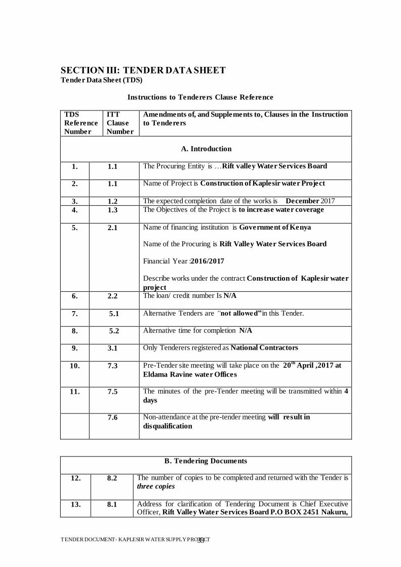
SECTION III: TENDER DATA SHEET Tender Data Sheet (TDS)
Instructions to Tenderers Clause Reference
TDS
Reference
Number
ITT
Clause
Number
Amendments of, and Supplements to, Clauses in the Instruction
to Tenderers
A. Introduction
1. 1.1 The Procuring Entity is …Rift valley Water Services Board
2. 1.1 Name of Project is Construction of Kaplesir water Project
3. 1.2 The expected completion date of the works is December 2017
4. 1.3 The Objectives of the Project is to increase water coverage
5. 2.1 Name of financing institution is Government of Kenya Name of the Procuring is Rift Valley Water Services Board Financial Year :2016/2017 Describe works under the contract Construction of Kaplesir water
project 6. 2.2 The loan/ credit number Is N/A
7. 5.1
Alternative Tenders are “not allowed‖in this Tender.
8. 5.2
Alternative time for completion N/A
9. 3.1 Only Tenderers registered as National Contractors
10. 7.3
Pre-Tender site meeting will take place on the 20th
April ,2017 at
Eldama Ravine water Offices
11. 7.5 The minutes of the pre-Tender meeting will be transmitted within 4
days
7.6 Non-attendance at the pre-tender meeting will result in
disqualification
B. Tendering Documents
12. 8.2 The number of copies to be completed and returned with the Tender is three copies
13. 8.1 Address for clarification of Tendering Document is Chief Executive Officer, Rift Valley Water Services Board P.O BOX 2451 Nakuru,
TENDER DOCUMENT- KAPLESIR WATER SUPPLY PROJECT 34
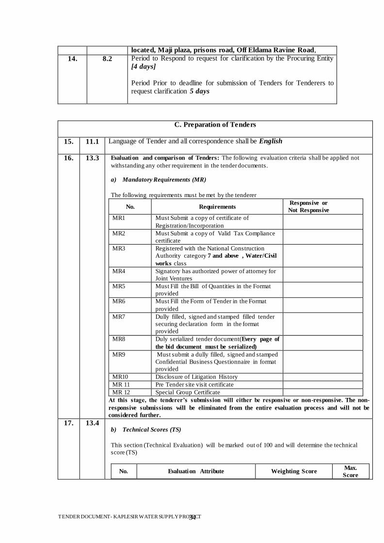
located, Maji plaza, prisons road, Off Eldama Ravine Road,
14. 8.2 Period to Respond to request for clarification by the Procuring Entity [4 days] Period Prior to deadline for submission of Tenders for Tenderers to request clarification 5 days
C. Preparation of Tenders
15.
11.1 Language of Tender and all correspondence shall be English
16. 13.3 Evaluation and comparison of Tenders: The following evaluation criteria shall be applied not
withstanding any other requirement in the tender documents.
a) Mandatory Requirements (MR)
The following requirements must be met by the tenderer
No. Requirements Responsive or
Not Responsive
MR1 Must Submit a copy of certificate of
Registration/Incorporation
MR2 Must Submit a copy of Valid Tax Compliance
certificate
MR3 Registered with the National Construction
Authority category 7 and above , Water/Civil
works class
MR4 Signatory has authorized power of attorney for
Joint Ventures
MR5 Must Fill the Bill of Quantities in the Format
provided
MR6 Must Fill the Form of Tender in the Format
provided
MR7 Dully filled, signed and stamped filled tender
securing declaration form in the format
provided
MR8 Duly serialized tender document(Every page of
the bid document must be serialized)
MR9 Must submit a dully filled, signed and stamped
Confidential Business Questionnaire in format
provided
MR10 Disclosure of Litigation History
MR 11 Pre Tender site visit certificate
MR 12 Special Group Certificate
At this stage, the tenderer‘s submission will either be responsive or non-responsive. The non-
responsive submissions will be eliminated from the entire evaluation process and will not be
considered further.
17. 13.4 b) Technical Scores (TS)
This section (Technical Evaluation) will be marked out of 100 and will determine the technical
score (TS)
No. Evaluation Attribute Weighting Score Max.
Score
TENDER DOCUMENT- KAPLESIR WATER SUPPLY PROJECT 35
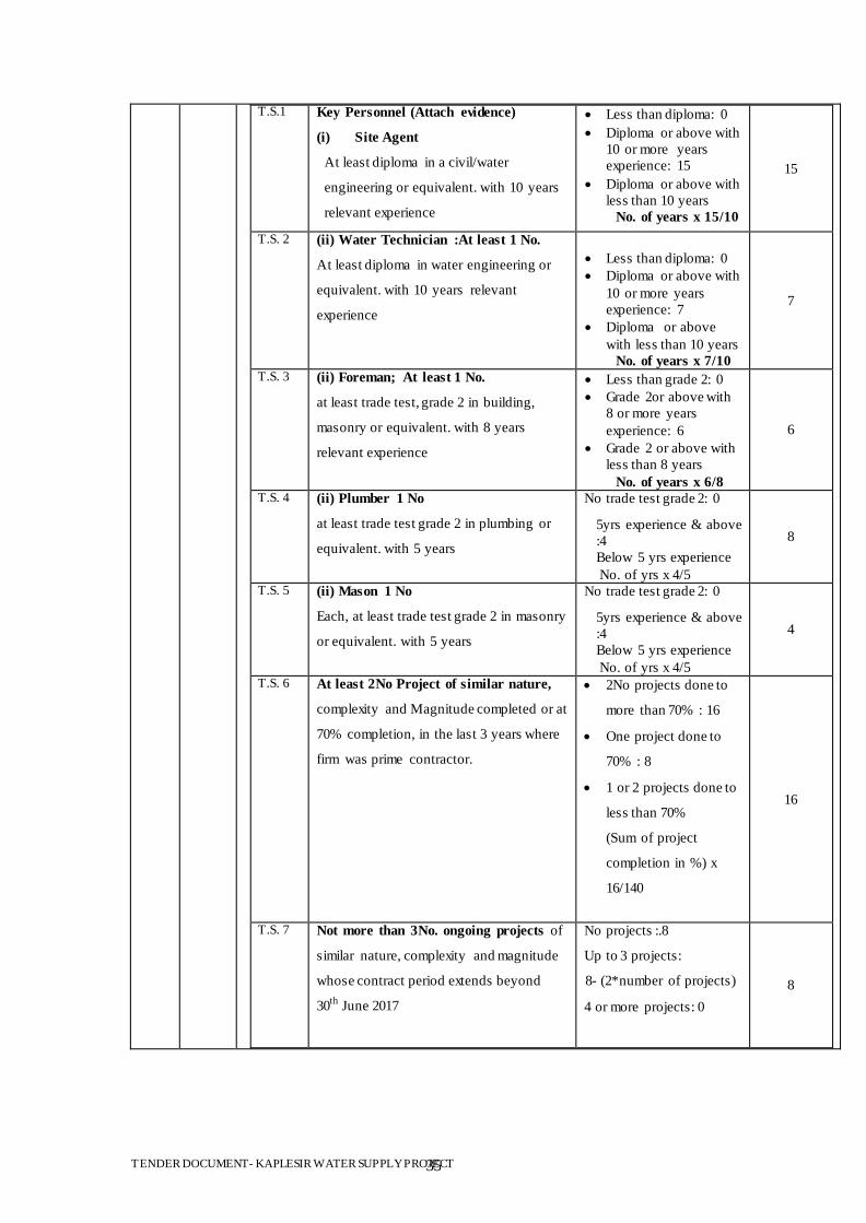
T.S.1 Key Personnel (Attach evidence)
(i) Site Agent
At least diploma in a civil/water
engineering or equivalent. with 10 years
relevant experience
Less than diploma: 0
Diploma or above with
10 or more years
experience: 15
Diploma or above with
less than 10 years
No. of years x 15/10
15
T.S. 2 (ii) Water Technician :At least 1 No.
At least diploma in water engineering or
equivalent. with 10 years relevant
experience
Less than diploma: 0
Diploma or above with
10 or more years
experience: 7
Diploma or above
with less than 10 years
No. of years x 7/10
7
T.S. 3 (ii) Foreman; At least 1 No.
at least trade test, grade 2 in building,
masonry or equivalent. with 8 years
relevant experience
Less than grade 2: 0
Grade 2or above with
8 or more years
experience: 6
Grade 2 or above with
less than 8 years
No. of years x 6/8
6
T.S. 4 (ii) Plumber 1 No
at least trade test grade 2 in plumbing or
equivalent. with 5 years
No trade test grade 2: 0
5yrs experience & above
:4
Below 5 yrs experience
No. of yrs x 4/5
8
T.S. 5 (ii) Mason 1 No
Each, at least trade test grade 2 in masonry
or equivalent. with 5 years
No trade test grade 2: 0
5yrs experience & above
:4
Below 5 yrs experience
No. of yrs x 4/5
4
T.S. 6 At least 2No Project of similar nature,
complexity and Magnitude completed or at
70% completion, in the last 3 years where
firm was prime contractor.
2No projects done to
more than 70% : 16
One project done to
70% : 8
1 or 2 projects done to
less than 70%
(Sum of project
completion in %) x
16/140
16
T.S. 7 Not more than 3No. ongoing projects of
similar nature, complexity and magnitude
whose contract period extends beyond
30th
June 2017
No projects :.8
Up to 3 projects:
8- (2*number of projects)
4 or more projects: 0
8
TENDER DOCUMENT- KAPLESIR WATER SUPPLY PROJECT 36
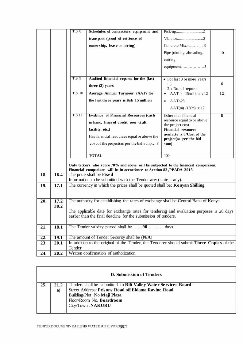
T.S. 8 Schedules of contractors equipment and
transport (proof of evidence of
ownership, lease or hiring)
Pick-up...........................2
Vibrator..........................2
Concrete Mixer...............3
Pipe jointing ,threading,
cutting
equipment………………3
10
T.S. 9 Audited financial reports for the (last
three (3) years
For last 3 or more years
: 6
2 x No. of reports
6
T.S. 10 Average Annual Turnover (AAT) for
the last three years is Ksh 15 million
AAT >= 15million : 12
AAT<25;
AAT(m) /15(m) x 12
12
T.S.11 Evidence of Financial Resources (cash
in hand, lines of credit, over draft
facility, etc.)
Has financial resources equal or above the
cost of the project(as per the bid sum)… 8
Other than financial
resource equal to or above
the project cost.
Financial resource
available x 8/Cost of the
project(as per the bid
sum)
8
TOTAL 100
Only bidders who score 70% and above will be subjected to the financial comparison.
Financial comparison will be in accordance to Section 82 ,PPADA 2015
18. 16.4 The price shall be Fixed Information to be submitted with the Tender are: (state if any).
19. 17.1
The currency in which the prices shall be quoted shall be: Kenyan Shilling
20. 17.2
30.2
The authority for establishing the rates of exchange shall be Central Bank of Kenya. The applicable date for exchange rates for tendering and evaluation purposes is 28 days earlier than the final deadline for the submission of tenders.
21. 18.1 The Tender validity period shall be ……90……….. days.
22. 19.1 The amount of Tender Security shall be (N/A)
23. 20.1
In addition to the original of the Tender, the Tenderer should submit Three Copies of the Tender
24. 20.2 Written confirmation of authorization
D. Submission of Tenders
25. 21.2
a)
Tenders shall be submitted to Rift Valley Water Services Board: Street Address: Prisons Road off Eldama Ravine Road Building/Plot No.Maji Plaza Floor/Room No. Boardroom City/Town .NAKURU
TENDER DOCUMENT- KAPLESIR WATER SUPPLY PROJECT 37
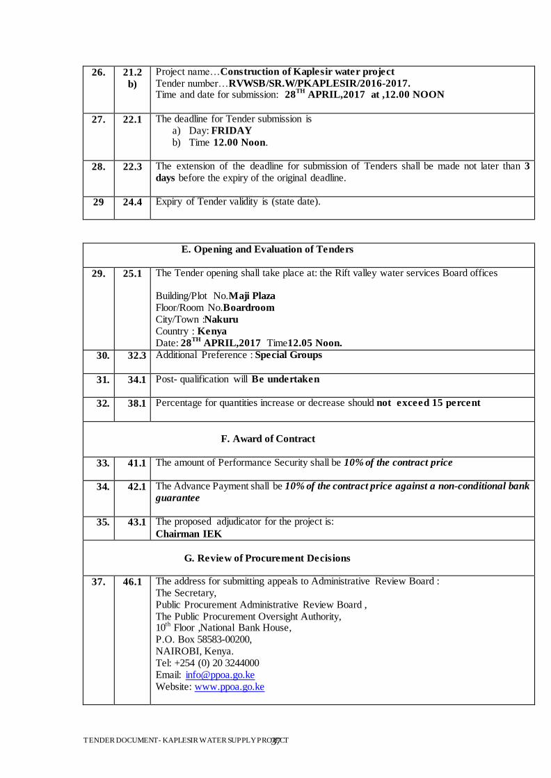
26. 21.2
b)
Project name…Construction of Kaplesir water project Tender number…RVWSB/SR.W/PKAPLESIR/2016-2017. Time and date for submission: 28
TH APRIL,2017 at ,12.00 NOON
27. 22.1 The deadline for Tender submission is a) Day: FRIDAY b) Time 12.00 Noon.
28. 22.3 The extension of the deadline for submission of Tenders shall be made not later than 3
days before the expiry of the original deadline.
29 24.4 Expiry of Tender validity is (state date).
E. Opening and Evaluation of Tenders
29. 25.1 The Tender opening shall take place at: the Rift valley water services Board offices Building/Plot No.Maji Plaza Floor/Room No.Boardroom City/Town :Nakuru
Country : Kenya Date: 28
TH APRIL,2017 Time12.05 Noon.
30. 32.3 Additional Preference : Special Groups
31. 34.1 Post- qualification will Be undertaken
32. 38.1 Percentage for quantities increase or decrease should not exceed 15 percent
F. Award of Contract
33. 41.1 The amount of Performance Security shall be 10% of the contract price
34. 42.1 The Advance Payment shall be 10% of the contract price against a non-conditional bank
guarantee
35. 43.1 The proposed adjudicator for the project is:
Chairman IEK
G. Review of Procurement Decisions
37. 46.1 The address for submitting appeals to Administrative Review Board : The Secretary, Public Procurement Administrative Review Board , The Public Procurement Oversight Authority, 10
th Floor ,National Bank House,
P.O. Box 58583-00200, NAIROBI, Kenya. Tel: +254 (0) 20 3244000 Email: [email protected] Website: www.ppoa.go.ke
TENDER DOCUMENT- KAPLESIR WATER SUPPLY PROJECT 38
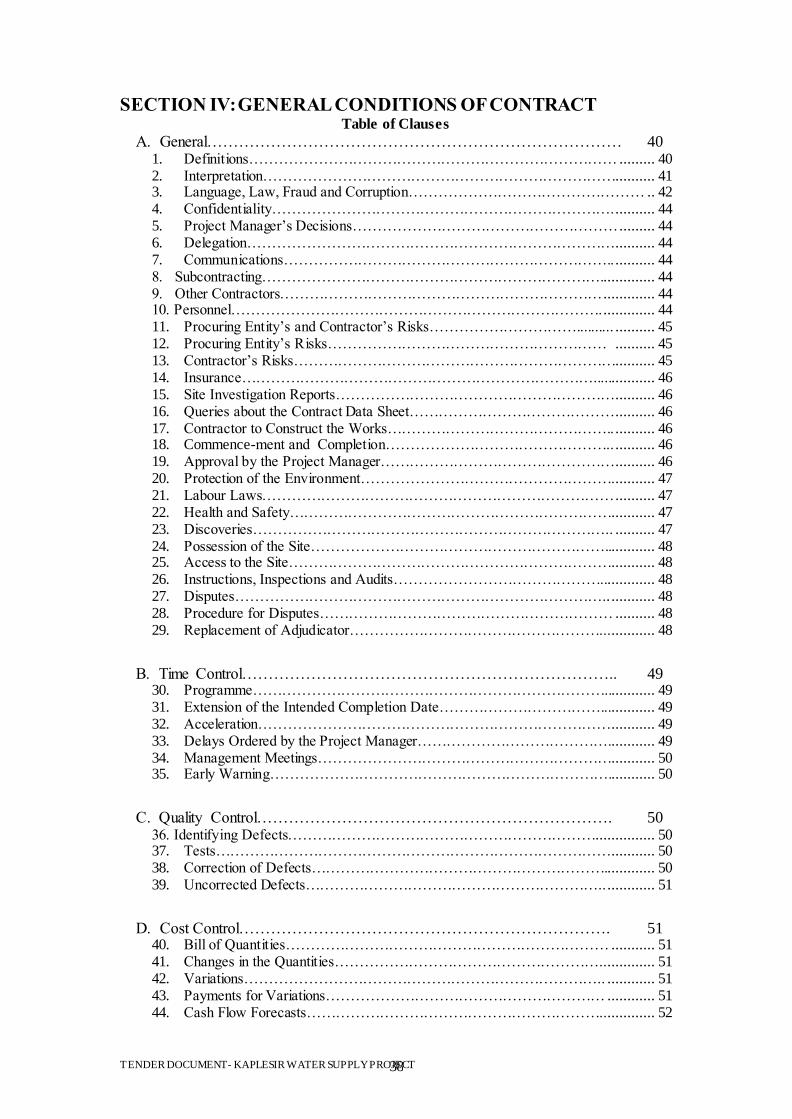
SECTION IV: GENERAL CONDITIONS OF CONTRACT Table of Clauses
A. General…………………………………………………………………… 40 1. Definitions………………………………………………………………… ......... 40 2. Interpretation……………………………………………………………….......... 41 3. Language, Law, Fraud and Corruption………………………………………… .. 42 4. Confidentiality……………………………………………………………. .......... 44 5. Project Manager‟s Decisions……………………………………………… ......... 44 6. Delegation………………………………………………………………… .......... 44 7. Communications………………………………………………………….. .......... 44 8. Subcontracting…………………………………………………………….............. 44 9. Other Contractors………………………………………………………… ............. 44 10. Personnel…………………………………………………………………. ............. 44 11. Procuring Entity‟s and Contractor‟s Risks………………………….......... .......... 45 12. Procuring Entity‟s Risks………………………………………………… .......... 45 13. Contractor‟s Risks………………………………………………………….......... 45 14. Insurance………………………………………………………………................ 46 15. Site Investigation Reports………………………………………………… .......... 46 16. Queries about the Contract Data Sheet…………………………………… .......... 46 17. Contractor to Construct the Works……………………………………….. .......... 46 18. Commence-ment and Completion……………………………………….. .......... 46 19. Approval by the Project Manager………………………………………… .......... 46 20. Protection of the Environment……………………………………………. .......... 47 21. Labour Laws……………………………………………………………… .......... 47 22. Health and Safety…………………………………………………………........... 47 23. Discoveries……………………………………………………………….. .......... 47 24. Possession of the Site……………………………………………………............. 48 25. Access to the Site…………………………………………………………........... 48 26. Instructions, Inspections and Audits…………………………………….............. 48 27. Disputes………………………………………………………………….. ........... 48 28. Procedure for Disputes…………………………………………………… .......... 48 29. Replacement of Adjudicator……………………………………………... ........... 48
B. Time Control…………………………………………………………….. 49 30. Programme………………………………………………………………............. 49 31. Extension of the Intended Completion Date…………………………….............. 49 32. Acceleration……………………………………………………………… ........... 49 33. Delays Ordered by the Project Manager…………………………………............ 49 34. Management Meetings……………………………………………………........... 50 35. Early Warning……………………………………………………………............ 50
C. Quality Control…………………………………………………………. 50 36. Identifying Defects………………………………………………………............... 50 37. Tests……………………………………………………………………… ........... 50 38. Correction of Defects……………………………………………………............. 50 39. Uncorrected Defects…………………………………………………….. ............ 51
D. Cost Control……………………………………………………………. 51 40. Bill of Quantities………………………………………………………… ........... 51 41. Changes in the Quantities……………………………………………….. ............ 51 42. Variations……………………………………………………………….. ............ 51 43. Payments for Variations………………………………………………… ............ 51 44. Cash Flow Forecasts…………………………………………………….. ............ 52
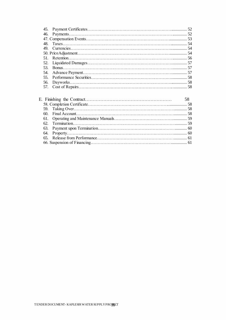
TENDER DOCUMENT- KAPLESIR WATER SUPPLY PROJECT 39
45. Payment Certificates…………………………………………………….............. 52 46. Payments…………………………………………………………………............ 52 47. Compensation Events……………………………………………………............... 53 48. Taxes…………………………………………………………………….............. 54 49. Currencies……………………………………………………………….. ............ 54 50. PriceAdjustment………………………………………………………… ............... 54 51. Retention…………………………………………………………………............ 56 52. Liquidated Damages…………………………………………………….. ............ 57 53. Bonus……………………………………………………………………. ............ 57 54. Advance Payment……………………………………………………….. ............ 57 55. Performance Securities………………………………………………….. ............ 58 56. Dayworks………………………………………………………………............... 58 57. Cost of Repairs………………………………………………………….. ............ 58
E. Finishing the Contract………………………………………………… 58 58. Completion Certificate………………………………………………….. ............... 58 59. Taking Over……………………………………………………………… ........... 58 60. Final Account…………………………………………………………… ............ 58 61. Operating and Maintenance Manuals…………………………………… ............ 59 62. Termination……………………………………………………………… ........... 59 63. Payment upon Termination……………………………………………… ........... 60 64. Property…………………………………………………………………. ............ 60 65. Release from Performance……………………………………………… ............ 61 66. Suspension of Financing………………………………………………… .............. 61
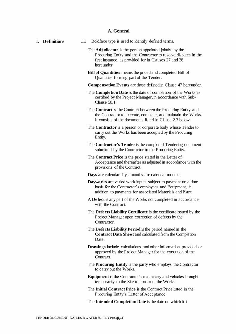
TENDER DOCUMENT- KAPLESIR WATER SUPPLY PROJECT 40
A. General
1. Definitions 1.1 Boldface type is used to identify defined terms.
The Adjudicator is the person appointed jointly by the Procuring Entity and the Contractor to resolve disputes in the first instance, as provided for in Clauses 27 and 28 hereunder.
Bill of Quantities means the priced and completed Bill of Quantities forming part of the Tender.
Compensation Events are those defined in Clause 47 hereunder.
The Completion Date is the date of completion of the Works as certified by the Project Manager, in accordance with Sub-Clause 58.1.
The Contract is the Contract between the Procuring Entity and the Contractor to execute, complete, and maintain the Works. It consists of the documents listed in Clause 2.3 below.
The Contractor is a person or corporate body whose Tender to carry out the Works has been accepted by the Procuring Entity.
The Contractor‘s Tender is the completed Tendering document submitted by the Contractor to the Procuring Entity.
The Contract Price is the price stated in the Letter of Acceptance and thereafter as adjusted in accordance with the provisions of the Contract.
Days are calendar days; months are calendar months.
Dayworks are varied work inputs subject to payment on a time basis for the Contractor‟s employees and Equipment, in addition to payments for associated Materials and Plant.
A Defect is any part of the Works not completed in accordance with the Contract.
The Defects Liability Certificate is the certificate issued by the Project Manager upon correction of defects by the Contractor.
The Defects Liability Period is the period named in the Contract Data Sheet and calculated from the Completion Date.
Drawings include calculations and other information provided or approved by the Project Manager for the execution of the Contract.
The Procuring Entity is the party who employs the Contractor to carry out the Works.
Equipment is the Contractor‟s machinery and vehicles brought temporarily to the Site to construct the Works.
The Initial Contract Price is the Contract Price listed in the Procuring Entity‟s Letter of Acceptance.
The Intended Completion Date is the date on which it is
TENDER DOCUMENT- KAPLESIR WATER SUPPLY PROJECT 41
intended that the Contractor shall complete the Works. The Intended Completion Date is specified in the Contract Data
Sheet. The Intended Completion Date may be revised only by the Project Manager by issuing an extension of time or an acceleration order.
Materials are all supplies, including consumables, used by the Contractor for incorporation in the Works.
Plant is any integral part of the Works that shall have a mechanical, electrical, chemical, or biological function.
The Project Manager is the person named in the Contract Data
Sheet (or any other competent person appointed by the Procuring Entity and notified to the Contractor, to act in replacement of the Project Manager) who is responsible for supervising the execution of the Works and administering the Contract and shall be an “Architect” or a “Quantity Surveyor” registered under the Architects and Quantity Surveyors Act Cap 525 or an “Engineer” registered under Engineers Registration Act Cap 530.
The Site is the area defined as such in the Contract Data Sheet.
Site Investigation Reports are those that were included in the Tendering documents and are factual and interpretative reports about the surface and subsurface conditions at the Site.
Specification means the Specification of the Works included in the Contract and any modification or addition made or approved by the Project Manager.
The Start Date is given in the Contract Data Sheet. It is the latest date when the Contractor shall commence execution of the Works. It does not necessarily coincide with any of the Site Possession Dates.
A Subcontractor is a person or corporate body who has a Contract with the Contractor to carry out a part of the work in the Contract, which includes work on the Site.
Temporary Works are works designed, constructed, installed, and removed by the Contractor that are needed for construction or installation of the Works.
A Variation is an instruction given by the Project Manager that varies the Works.
The Works are what the Contract requires the Contractor to construct, install, and turn over to the Procuring Entity, as defined in the Contract Data Sheet.
“Force Majeure” means an event which is beyond the reasonable control of a Party and which makes a Party‟s performance of its obligations under the Contract impossible or so impractical as to be considered impossible under the circumstances.
2. Interpretation 2.1 In interpreting these Conditions of Contract, singular also means plural, male also means female or neuter, and the other
TENDER DOCUMENT- KAPLESIR WATER SUPPLY PROJECT 42
way round. Headings have no significance. Words have their normal meaning under the language of the Contract unless specifically defined. The Project Manager will provide instructions clarifying queries about these Conditions of Contract.
2.2 If sectional completion is specified in the Contract Data Sheet, references in the Conditions of Contract to the Works, the Completion Date, and the Intended Completion Date apply to any Section of the Works (other than references to the Completion Date and Intended Completion Date for the whole of the Works).
2.3 The documents forming the Contract shall be interpreted in the order of priority given in the Contract Data Sheet:
(1) Agreement;
(2) Letter of Acceptance;
(3) Contract Data Sheet;
(4) Conditions of Contract;
(5) Technical Specifications;
(6) Contractor‟s Tender;
(7) Drawings;
(8) Bill of Quantities; and
(9) Any other document listed in the Contract Data Sheet as
forming part of the Contract.
3. Language, Law,
Fraud and
Corruption
3.1 The language of the Contract and the law governing the Contract are stated in the Contract Data Sheet.
3.2 The Government requires that Procuring Entities (including beneficiaries of Government funded projects) as well as Tenderers/Suppliers/Contractors under Government financed contracts, observe the highest standard of ethics during the procurement and execution of such contracts. It is the responsibility of the Procuring Entity to ensure that Tenderers, suppliers, and contractors and their subcontractors observe the highest standard of ethics during the procurement and execution of such contracts. In pursuance of this policy:
For the purpose of this provision, the following definitions are
provided: (i). “Corruption” has the meaning assigned to it in the
Anti Corruption and Economic Crime Act 2003 and includes the offering, giving, receiving or soliciting of anything of value to influence the action of a public official in the procurement or disposal process or in contract execution;
(ii). “Fraudulent Practice” includes a misrepresentation of fact in order to influence a procurement or
TENDER DOCUMENT- KAPLESIR WATER SUPPLY PROJECT 43
disposal process or the execution of a contract to the detriment of the Procuring Entity and includes collusive practices amongst Tenderers prior to or after Tender submission designed to establish Tender prices at artificial non competitive levels and deprive the Procuring Entity of the benefits of free and open competition;
(iii). ―Collusive Practice‖ meansan arrangement between two or more suppliers, contractors and subcontractors designed to achieve an improper purpose, including to influence improperly the actions of the Procuring Entity prior to or after Tender submission , designed to establish Tender prices at artificial non competitive levels and to deprive the Procuring Entity of the benefit of free and open competition;
(iv). ―Coercive Practice‖ means impairing or harming, or threatening to impair or harm, directly or indirectly a supplier, contractor or subcontractor or the property of any of them to influence improperly the actions of a Procuring Entity;
(v). ―Obstructive Practice‖ means deliberately destroying, falsifying, altering or concealing of evidence material to the investigation or making false statements to investigators in order to materially impede an investigation into allegations of a corrupt, fraudulent, coercive or collusive practice; and /or threatening, harassing or intimidating any party to prevent it from disclosing its knowledge of matters relevant to the investigation or from pursuing the investigation.
A Procuring Entity has the right to require that Tenderers, suppliers, and contractors and their subcontractors permit persons duly appointed by KACC/PPOA/KNAO to inspect their accounts and records and other documents relating to the Tender submission and contract performance;
The Procuring Entity will reject a proposal for award if it determines that the Tenderer recommended for award has engaged in corrupt, fraudulent practices or others stated under Clause 44.1.a in competing for the contract;
In pursuit of the policy defined in sub-Clause 44.1 the Procuring Entity will cancel the portion of the funds allocated to a contract for goods, works, or services if it at any time determines that corrupt or fraudulent practices were engaged in by representatives of the Procuring Entity or Approving Authority or of a beneficiary of the funds during the procurement or the execution of that contract;
In the event that the Procuring Entity or Approving Authority does not take timely and appropriate action satisfactory to the Government of Kenya to remedy the situation, then the Director-General may order an investigation of procurement
TENDER DOCUMENT- KAPLESIR WATER SUPPLY PROJECT 44
proceedings for the purpose of determining whether there has been a breach of the Public Procurement and Disposal Act, 2005.
3.3 The Director-General may, on the advice of the Advisory
Board, debar a person from participating in procurement proceedings on the ground that the person has committed an offence under the Public Procurement and Disposal Act, 2005. A debarment shall be for a period of time of not less than five years.Before a person is so debarred, he/she will be given an opportunity to make representations to the Director-General and may request the Review Board to review the debarment.
3.4 Any communication between the Tenderers and the
Procuring Entity related to matters of alleged fraud or corruption must be made in writing.
4. Confidentiality 4.1 The Service Providers, their Subcontractors, and the Personnel of either of them shall not disclose any proprietary or confidential information relating to the Project, the Services, this Contract, or the Procuring Entity‟s business or operations without the
prior written consent of the Procuring Entity.
5. Project
Manager‘s
Decisions
5.1 Except where otherwise specifically stated, the Project Manager will decide contractual matters between the Procuring Entity
and the Contractor in the role representing the Procuring Entity.
6. Delegation 6.1 The Project Manager may delegate any of his duties and responsibilities to other people except to the Adjudicator, after notifying the Contractor, and may cancel any delegation after
notifying the Contractor.
7. Communication
s
7.1 Communications between parties that are referred to in the Conditions shall be effective only when in writing. A notice
shall be effective only when it is delivered.
8. Subcontracting 8.1 The Contractor may subcontract with the approval of the Project Manager, but may not assign the Contract without the approval of the Procuring Entity in writing. Subcontracting
shall not alter the Contractor‟s obligations.
9. Other
Contractors
9.1 The Contractor shall cooperate and share the Site with other contractors, public authorities, utilities, and the Procuring Entity between the dates given in the Schedule of Other Contractors, as referred to in the Contract Data Sheet. The Contractor shall also provide facilities and services for them as described in the Schedule. The Procuring Entity may modify the Schedule of Other Contractors, and shall notify the Contractor of any such
modification
10. Personnel 10.1 The Contractor shall employ the key personnel named in the Schedule of Key Personnel, as referred to in the Contract Data
Sheet, who shall be appropriately qualified and registered with the appropriate bodies to carry out the functions stated in the Schedule or other personnel approved by the Project Manager.
TENDER DOCUMENT- KAPLESIR WATER SUPPLY PROJECT 45
The Project Manager will approve any proposed replacement of key personnel only if their relevant qualifications and abilities are substantially equal to or better than those of the personnel
listed in the Schedule.
10.2 If the Project Manager asks the Contractor to remove a person who is a member of the Contractor‟s staff or work force, stating the reasons, the Contractor shall ensure that the person leaves the Site within seven days and has no further connection
with the work in the Contract.
11. Procuring
Entity‘s and
Contractor‘s
Risks
11.1 The Procuring Entity carries the risks which this Contract states are Procuring Entity‟s risks, and the Contractor carries the risks
which this Contract states are Contractor‟s risks.
12. Procuring
Entity‘s Risks
12.1 From the Start Date until the Defects Correction Certificate has
been issued, the following are Procuring Entity‟s risks:
a) The risk of personal injury, death, or loss of or damage to property (excluding the Works, Plant, Materials, and Equipment), which are
due to:
(i) Use or occupation of the Site by the Works or for the purpose of the Works, which is the unavoidable
result of the Works; or
(ii) Negligence, breach of statutory duty, or interference with any legal right by the Procuring Entity or by any person employed by or contracted
to him except the Contractor.
b) The risk of damage to the Works, Plant, Materials, and Equipment to the extent that it is due to a fault of the Procuring Entity or in the Procuring Entity‟s design, or due to war or radioactive contamination directly affecting the country where the Works are
to be executed.
12.2 From the Completion Date until the Defects Correction Certificate has been issued, the risk of loss of or damage to the Works, Plant, and Materials is an Procuring Entity‟s risk except
loss or damage due to:
(a) A Defect which existed on the Completion Date;
(b) An event occurring before the Completion Date, which
was not itself an Procuring Entity‟s risk; or
(c) The activities of the Contractor on the Site after the
Completion Date.
13. Contractor‘s
Risks
13.1 From the Starting Date until the Defects Correction Certificate has been issued, the risks of personal injury, death, and loss of or damage to property (including, without limitation, the Works, Plant, Materials, and Equipment) which are not
Procuring Entity‟s risks are Contractor‟s risks.
TENDER DOCUMENT- KAPLESIR WATER SUPPLY PROJECT 46
14. Insurance 14.1 The Contractor shall provide, in the joint names of the Procuring Entity and the Contractor, insurance cover from the Start Date to the end of the Defects Liability Period, in the amounts and deductibles stated in the Contract Data Sheet for the following events which are due to the Contractor‟s risks:
(a) Loss of or damage to the Works, Plant, and Materials;
(b) Loss of or damage to Equipment;
(c) Loss of or damage to property (except the Works, Plant, Materials, and Equipment) in connection with the
Contract; and
(d) Personal injury or death.
14.2 Policies and certificates for insurance shall be delivered by the Contractor to the Project Manager for the Project Manager‟s approval before the Start Date. All such insurance shall provide for compensation to be payable in the types and proportions of
currencies required to rectify the loss or damage incurred.
14.3 If the Contractor does not provide any of the policies and certificates required, the Procuring Entity may effect the insurance which the Contractor should have provided and recover the premiums the Procuring Entity has paid from payments otherwise due to the Contractor or, if no payment is
due, the payment of the premiums shall be a debt due.
14.4 Alterations to the terms of insurance shall not be made without
the approval of the Project Manager.
14.5 Both parties shall comply with any conditions of the insurance
policies.
15. Site
Investigation
Reports
15.1 The Contractor, in preparing the Tender, shall rely on any Site Investigation Reports referred to in the Contract Data Sheet,
supplemented by any information available to the Tenderers.
16. Queries about
the Contract
Data Sheet
16.1 The Project Manager will clarify queries on the Contract Data
Sheet.
17. Contractor to
Construct the
Works
17.1 The Contractor shall construct and install the Works in accordance with the Specifications and Drawings.
18. Commencement
and Completion
18.1 The Contractor may commence execution of the Works on the Start Date and shall carry out the Works in accordance with the Programme submitted by the Contractor, as updated with the approval of the Project Manager, and complete them by the
Intended Completion Date.
19. Approval by the
Project
Manager
19.1 The Contractor shall submit Specifications and Drawings showing the proposed Temporary Works to the Project Manager, who is to approve them if they comply with the
Specifications and Drawings.
TENDER DOCUMENT- KAPLESIR WATER SUPPLY PROJECT 47
19.2 The Contractor shall be responsible for the design of
Temporary Works.
19.3 The Project Manager‟s approval shall not alter the Contractor‟s
responsibility for design of the Temporary Works.
19.4 The Contractor shall obtain approval of third parties to the
design of the Temporary Works, where required.
19.5 All Drawings prepared by the Contractor for the execution of the temporary or permanent Works, are subject to prior
approval by the Project Manager before their use.
20. Protection of
the
Environment
20.1 The Contractors shall take all reasonable steps to protect the environment and to limit damage and nuisance to people and property resulting from pollution, noise and other results of his
operations.
20.2 The Contractors shall ensure that emissions, surface discharges and effluent from his activities shall not exceed prescribed
values in the environmental laws.
21. Labour Laws 21.2 The Contractor shall comply with all the relevant labour laws applicable in the Country, including laws relating to workers employment, working hours, health, safety, welfare, and immigration, and shall allow them all their legal rights.
21.2 The Contractor shall require his employees to obey all
applicable laws, including those concerning safety at work.
22. Health and
Safety
22.1 The Contractor shall at all times take all reasonable precautions
to maintain the health and safety of his personnel.
22.2 The Contractor shall ensure that first aid facilities are available at all times at the site and that suitable arrangements are made for all necessary welfare and hygiene requirements and for the
prevention of epidemics.
22.3 The Contractor shall notify the Procuring Entity details of any accident as soon as practicable after its occurrence. The Contractor shall maintain records and make reports concerning health, safety, and welfare of persons, and damage to the
property, as the Procuring Entity may reasonably require.
22.4 The Contractor shall conduct an HIV-Aids awareness programme, and shall take other such measures as specified in the Contract Data Sheet to reduce the risk of transfer of HIV virus between and among Contractor personnel, the Procuring Entity‟s Staff and the surrounding community.
23. Discoveries 23.1 Anything of historical or other interest or of significant value unexpectedly discovered on the Site shall be the property of the Procuring Entity. The Contractor shall notify the Project Manager of such discoveries and carry out the Project
Manager's instructions for dealing with them.
TENDER DOCUMENT- KAPLESIR WATER SUPPLY PROJECT 48
24. Possession of
the Site
24.1 The Procuring Entity shall give possession of all parts of the Site to the Contractor. If possession of a part is not given by the date stated in the Contract Data Sheet, the Procuring Entity will be deemed to have delayed the start of the relevant activities, and this will be a Compensation Event.
25. Access to the
Site
25.1 The Contractor shall allow the Project Manager and any person authorized by the Project Manager access to the Site and to any place where work in connection with the Contract is being
carried out or is intended to be carried out.
26. Instructions,
Inspections and
Audits
26.1 The Contractor shall carry out all instructions of the Project Manager which comply with the applicable laws where the Site
is located.
26.2 The Contractor shall permit the Kenya Government to inspect the Contractor‟s accounts and records relating to the performance of the Contractor and to have them audited by auditors appointed by the Kenya Government, if so required by
the Kenya Government
27. Disputes 27. 1 If the Contractor believes that a decision taken by the Project Manager was either outside the authority given to the Project Manager by the Contract or that the decision was wrongly taken, the decision shall be referred to the Adjudicator within
14 days of the notification of the Project Manager‟s decision.
28. Procedure for
Disputes
28.1 The Adjudicator shall give a decision in writing within 28 days
of receipt of a notification of a dispute.
28.2 The Adjudicator shall be paid by the hour at the rate specified in the Tender Data Sheet and Contract Data Sheet, together with reimbursable expenses of the types specified in the Contract Data Sheet, and the cost shall be divided equally between the Procuring Entity and the Contractor, whatever decision is reached by the Adjudicator. Either party may refer a decision of the Adjudicator to an Arbitrator within 28 days of the Adjudicator‟s written decision. If neither party refers the dispute to arbitration within the above 28 days, the
Adjudicator‟s decision will be final and binding.
28.3 The arbitration shall be conducted in accordance with the arbitration procedure published by the institution named and in
the place shown in the Contract Data Sheet.
29. Replacement of
Adjudicator
29.1 Should the Adjudicator resign or die, or should the Procuring Entity and the Contractor agree that the Adjudicator is not functioning in accordance with the provisions of the Contract, a new Adjudicator will be jointly appointed by the Procuring Entity and the Contractor. In case of disagreement between the Procuring Entity and the Contractor, within 30 days, the Adjudicator shall be designated by the Appointing Authority designated in the Contract Data Sheet at the request of either
party, within 14 days of receipt of such request.
TENDER DOCUMENT- KAPLESIR WATER SUPPLY PROJECT 49
B. Time Control
30. Programme 30.1 Within the time stated in the Contract Data Sheet, the Contractor shall submit to the Project Manager for approval a Programme showing the general methods, arrangements, order, and timing for all the activities in the Works.
30.2 An update of the Programme shall be a programme showing the actual progress achieved on each activity and the effect of the progress achieved on the timing of the remaining work, including
any changes to the sequence of the activities.
30.3 The Contractor shall submit to the Project Manager for approval an updated Programme at intervals no longer than the period stated in the Contract Data Sheet. If the Contractor does not submit an updated Programme within this period, the Project Manager may withhold the amount stated in the Contract Data
Sheet from the next payment certificate and continue to withhold this amount until the next payment after the date on which the
overdue Programme has been submitted.
30.4 The Project Manager‟s approval of the Programme shall not alter the Contractor‟s obligations. The Contractor may revise the Programme and submit it to the Project Manager again at any time. A revised Programme shall show the effect of Variations
and Compensation Events
31. Extension of
the Intended
Completion
Date
31.1 The Project Manager shall extend the Intended Completion Date if a Compensation Event occurs or a Variation is issued which makes it impossible for Completion to be achieved by the Intended Completion Date without the Contractor taking steps to accelerate the remaining work, which would cause the Contractor
to incur additional cost.
31.2 The Project Manager shall decide whether and by how much to extend the Intended Completion Date within 21 days of the Contractor asking the Project Manager for a decision upon the effect of a Compensation Event or Variation and submitting full supporting information. If the Contractor has failed to give early warning of a delay or has failed to cooperate in dealing with a delay, the delay by this failure shall not be considered in
assessing the new Intended Completion Date.
32. Acceleration 32.1 When the Procuring Entity wants the Contractor to finish before the Intended Completion Date, the Project Manager will obtain priced proposals for achieving the necessary acceleration from the Contractor. If the Procuring Entity accepts these proposals, the Intended Completion Date will be adjusted accordingly and
confirmed by both the Procuring Entity and the Contractor.
32.2 If the Contractor‟s priced proposals for acceleration are accepted by the Procuring Entity, they shall be incorporated in the Contract Price and treated as a Variation.
33. Delays 33.1 The Project Manager may instruct the Contractor to delay the start

TENDER DOCUMENT- KAPLESIR WATER SUPPLY PROJECT 50
Ordered by
the Project
Manager
or progress of any activity within the Works.
34. Management
Meetings
34.1 Either the Project Manager or the Contractor may require the other to attend a management meeting. The business of a management meeting shall be to review the plans for remaining work and to deal with matters raised in accordance with the early
warning procedure.
34.2 The Project Manager shall record the business of management meetings and provide copies of the record to those attending the meeting and to the Procuring Entity. The responsibility of the parties for actions to be taken shall be decided by the Project Manager either at the management meeting or after the management meeting and stated in writing to all who attended the
meeting.
35. Early
Warning
35.1 The Contractor shall warn the Project Manager at the earliest opportunity of specific likely future events or circumstances that may adversely affect the quality of the work, increase the Contract Price or delay the execution of the Works. The Project Manager may require the Contractor to provide an estimate of the expected effect of the future event or circumstance on the Contract Price and Completion Date. The estimate shall be
provided by the Contractor as soon as reasonably possible.
35.2 The Contractor shall cooperate with the Project Manager in making and considering proposals for how the effect of such an event or circumstance can be avoided or reduced by anyone involved in the work and in carrying out any resulting instruction
of the Project Manager.
C. Quality Control
36. Identifying
Defects
36.1 The Project Manager shall check the Contractor‟s work and notify the Contractor of any Defects that are found. Such checking shall not affect the Contractor‟s responsibilities. The Project Manager may instruct the Contractor to search for a Defect and to uncover and test any work that the Project
Manager considers may have a Defect.
37. Tests 37.1 If the Project Manager instructs the Contractor to carry out a test not specified in the Specification to check whether any work has a Defect and the test shows that it does, the Contractor shall pay for the test and any samples. If there is no Defect, the test shall
be a Compensation Event.
38. Correction of
Defects
38.1 The Project Manager shall give notice to the Contractor of any Defects before the end of the Defects Liability Period, which begins at Completion, and is defined in the Contract Data Sheet. The Defects Liability Period shall be extended for as long as
Defects remain to be corrected.
38.2 Every time notice of a Defect is given, the Contractor shall correct the notified Defect within the length of time specified by
TENDER DOCUMENT- KAPLESIR WATER SUPPLY PROJECT 51
the Project Manager‟s notice.
38.3 If the Contractor has not corrected a defect within the time specified in the Procuring Entity‟s notice, a penalty for lack of performance will be paid by the Contractor. The amount to be paid will be calculated as a percentage of the cost of having the
defect correct, assessed as described in Clause 39.
39. Uncorrected
Defects
39.1 If the Contractor has not corrected a Defect within the time specified in the Project Manager‟s notice, the Project Manager will assess the cost of having the Defect corrected, and the Contractor will pay this amount.
D. Cost Control
40. Bill of
Quantities
40.1 The Bill of Quantities shall contain items for the construction, installation, testing, and commissioning work to be done by the
Contractor.
40.2 The Bill of Quantities is used to calculate the Contract Price. The Contractor shall be paid for the quantity of the work done at the rate in the Bill of Quantities for each item.
41. Changes in the
Quantities
41.1 If the final quantity of the work done differs from the quantity in the Bill of Quantities for the particular item by more than 25 percent, provided the change exceeds 1 percent of the Initial Contract Price, the Project Manager shall adjust the rate to allow
for the change.
41.2 The Project Manager shall not adjust rates from changes in quantities if thereby the Initial Contract Price is exceeded by more than 15 percent, except with the prior approval of the
Procuring Entity.
41.3 If requested by the Project Manager, the Contractor shall provide the Project Manager with a detailed cost breakdown of
any rate in the Bill of Quantities.
42. Variations 42.1 All Variations shall be included in the updated Programmes
produced by the Contractor.
43. Payments for
Variations
43.1 The Contractor shall provide the Project Manager with a quotation for carrying out the Variation when requested to do so by the Project Manager. The Project Manager shall assess the quotation, which shall be given within seven days of the request or within any longer period stated by the Project Manager and before the Variation is ordered.
43.2 If the work in the Variation corresponds with an item description in the Bill of Quantities and if, in the opinion of the Project Manager, the quantity of work is above the limit stated in Sub-Clause 41.1 or the timing of its execution do not cause the cost per unit of quantity to change, the rate in the Bill of Quantities shall be used to calculate the value of the Variation. If the cost per unit of quantity changes, or if the nature or timing of the work in the Variation does not correspond with items in
TENDER DOCUMENT- KAPLESIR WATER SUPPLY PROJECT 52
the Bill of Quantities, the quotation by the Contractor shall be in
the form of new rates for the relevant items of work.
43.3 If the Contractor‟s quotation is unreasonable, the Project Manager may order the Variation and make a change to the Contract Price, which shall be based on the Project Manager‟s own forecast of the effects of the Variation on the Contractor‟s
costs.
43.4 If the Project Manager decides that the urgency of varying the work would prevent a quotation being given and considered without delaying the work, no quotation shall be given and the
Variation shall be treated as a Compensation Event.
43.5 The Contractor shall not be entitled to additional payment for costs that could have been avoided by giving early warning.
44. Cash Flow
Forecasts
44.1 When the Programme is updated, the Contractor shall provide the Project Manager with an updated cash flow forecast. The cash flow forecast shall include different currencies, as defined in the Contract, converted as necessary using the Contract
exchange rates.
45. Payment
Certificates
45.1 The Contractor shall submit to the Project Manager monthly statements of the estimated value of the work executed less the
cumulative amount certified previously.
45.2 The Project Manager shall check the Contractor‟s monthly statement and certify the amount to be paid to the Contractor within twenty eight 28 days of receipt of the certificate from the
contractor.
45.3 The value of work executed shall be determined by the Project
Manager.
45.4 The value of work executed shall comprise the value of the
quantities of the items in the Bill of Quantities completed.
45.5 The value of work executed shall include the valuation of Variations and Compensation Events.
45.6 The Project Manager may exclude any item certified in a previous certificate or reduce the proportion of any item previously certified in any certificate in the light of later information.
45.7 The Project Manager shall not be bound to certify any payment, if the net amount, after all retentions and deductions would be less than minimum amount of Interim Payment Certificate stated in the Contract Data Sheet.
46. Payments 46.1 Payments shall be adjusted for deductions for advance payments and retention. The Procuring Entity shall pay the Contractor the amounts certified by the Project Manager within 28 days of the date of each certificate. If the Procuring Entity makes a late payment, the Contractor shall be paid interest on the late payment in the next payment Interest shall be calculated from
TENDER DOCUMENT- KAPLESIR WATER SUPPLY PROJECT 53
the date by which the payment should have been made up to the date when the late payment is made at the prevailing rate of interest for commercial borrowing for each of the currencies in which payments are made as indicated in the Contract Data Sheet..
46.2 If an amount certified is increased in a later certificate or as a result of an award by the Adjudicator or an Arbitrator, the Contractor shall be paid interest upon the delayed payment as set out in this clause. Interest shall be calculated from the date upon which the increased amount would have been certified in the absence of dispute.
46.3 Unless otherwise stated, all payments and deductions will be paid or charged in the proportions of currencies comprising the Contract Price.
46.4 Items of the Works for which no rate or price has been entered in will not be paid for by the Procuring Entity and shall be deemed covered by other rates and prices in the Contract.
47. Compensation
Events
47.1 The following shall be Compensation Events:
(a) The Procuring Entity does not give access to a part of the Site by the Site Possession Date stated in the Contract
Data Sheet.
(b) The Procuring Entity modifies the Schedule of Other Contractors in a way that affects the work of the Contractor under the Contract.
(c) The Project Manager orders a delay or does not issue Drawings, Specifications, or instructions required for execution of the Works on time.
(d) The Project Manager instructs the Contractor to uncover or to carry out additional tests upon work, which is then found to have no Defects.
(e) The Project Manager unreasonably does not approve a subcontract to be let.
(f) Ground conditions are substantially more adverse than could reasonably have been assumed before issuance of the Letter of Acceptance from the information issued to Tenderers (including the Site Investigation Reports), from information available publicly and from a visual
inspection of the Site.
(g) The Project Manager gives an instruction for dealing with an unforeseen condition, caused by the Procuring Entity, or additional work required for safety or other reasons.
(h) Other contractors, public authorities, utilities, or the Procuring Entity does not work within the dates and other constraints stated in the Contract, and they cause delay or
TENDER DOCUMENT- KAPLESIR WATER SUPPLY PROJECT 54
extra cost to the Contractor.
(i) The advance payment is delayed.
(j) The effects on the Contractor of any of the Procuring Entity‟s Risks.
(k) The Project Manager unreasonably delays issuing a Certificate of Completion.
(l) Other Compensation Events described in the Contract or determined by the Project Manager shall apply.
47.2 If a Compensation Event would cause additional cost or would prevent the work being completed before the Intended Completion Date, the Contract Price shall be increased and/or the Intended Completion Date shall be extended. The Project Manager shall decide whether and by how much the Contract Price shall be increased and whether and by how much the Intended Completion Date shall be extended.
47.3 As soon as information demonstrating the effect of each Compensation Event upon the Contractor‟s forecast cost has been provided by the Contractor, it shall be assessed by the Project Manager, and the Contract Price shall be adjusted accordingly. If the Contractor‟s forecast is deemed unreasonable, the Project Manager shall adjust the Contract Price based on the Project Manager‟s own forecast. The Project Manager will assume that the Contractor will react competently
and promptly to the event.
47.4 The Contractor shall not be entitled to compensation to the extent that the Procuring Entity‟s interests are adversely affected by the Contractor‟s not having given early warning or not
having cooperated with the Project Manager.
48. Taxes 48.1 The Project Manager shall adjust the Contract Price if taxes, duties, and other levies are changed between the date 28 days before the submission of Tenders for the Contract and the date of the last Completion certificate. The adjustment shall be the change in the amount of tax payable by the Contractor, provided such changes are not already reflected in the Contract Price or
are a result of Clause 50.
49. Currencies 49.1 Where payments are made in currencies other than the Kenya Shillings, the exchange rates used for calculating the amounts to be paid shall be the exchange rates stated in the Contractor‟s
Tender.
50. PriceAdjustme
nt
50.1 The amounts payable to the Contractor, in various currencies pursuant to Sub-Clause 45.1, shall be adjusted in respect of the rise or fall in the cost of labour, Contractor‟s Equipment, Plant, materials, and other inputs to the Works, by applying to such amounts the formulae prescribed in this clause based on the prevailing consumer price index obtained from the Central Bureau of Statistics or the monthly inflation rate issued by the
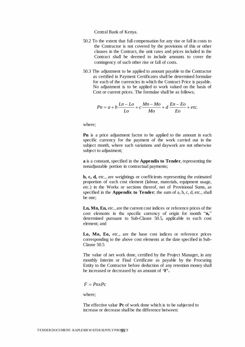
TENDER DOCUMENT- KAPLESIR WATER SUPPLY PROJECT 55
Central Bank of Kenya.
50.2 To the extent that full compensation for any rise or fall in costs to the Contractor is not covered by the provisions of this or other clauses in the Contract, the unit rates and prices included in the Contract shall be deemed to include amounts to cover the
contingency of such other rise or fall of costs.
50.3 The adjustment to be applied to amount payable to the Contractor as certified in Payment Certificates shall be determined formulae for each of the currencies in which the Contract Price is payable. No adjustment is to be applied to work valued on the basis of Cost or current prices. The formulae shall be as follows;
.etcEo
EoEnd
Mo
MoMnc
Lo
LoLnbaPn
where;
Pn is a price adjustment factor to be applied to the amount in each specific currency for the payment of the work carried out in the subject month, where such variations and daywork are not otherwise subject to adjustment;
a is a constant, specified in the Appendix to Tender, representing the nonadjustable portion in contractual payments; b, c, d, etc., are weightings or coefficients representing the estimated proportion of each cost element (labour, materials, equipment usage, etc.) in the Works or sections thereof, net of Provisional Sums, as specified in the Appendix to Tender; the sum of a, b, c, d, etc., shall be one; Ln, Mn, En, etc., are the current cost indices or reference prices of the cost elements in the specific currency of origin for month “n,” determined pursuant to Sub-Clause 50.5, applicable to each cost element; and Lo, Mo, Eo, etc., are the base cost indices or reference prices corresponding to the above cost elements at the date specified in Sub-Clause 50.5
The value of net work done, certified by the Project Manager, in any monthly Interim or Final Certificate as payable by the Procuring Entity to the Contractor before deduction of any retention money shall be increased or decreased by an amount of ‗F‘.
PnxPcF
where;
The effective value Pc of work done which is to be subjected to increase or decrease shall be the difference between:
TENDER DOCUMENT- KAPLESIR WATER SUPPLY PROJECT 56
(i) the amount which, in the opinion of the Project Manager, is due to the Contractor under Clause 45 (before deduction of retention money and before deducting sums previously paid on account) less:
any amount for payment or repayment of any advance payment;
any amount for materials on site (if any);
any amounts for nominated sub-contractors (if any)
any amounts for any other items based on actual cost or current prices; or
any sums for increase or decreases in the Contract Price paid under this Sub-Clause
and (ii) the amount calculated in accordance with (i) above of this
Sub-clause and included in the last preceding statement.
50.4The sources of indices shall be those listed in the Appendix to
Tender, as approved by the Engineer. Indices shall be appropriate for their purpose and shall relate to the Contractor‟s proposed source of supply of inputs on the basis of which his Contract Price and expected foreign currency requirements shall have been computed. As the proposed basis for price adjustment, the Contractor shall have submitted with his Tender the tabulation of Weightings and Source of Indices in the Appendix to Tender, which shall be subject to approval by the Engineer.
50.5 The base cost indices or prices shall be those prevailing on the
day 28 days prior to the latest date for submission of Tenders. Current indices or prices shall be those prevailing on the day 28 days prior to the last day of the period to which a particular Interim Payment Certificate is related. If at any time the current indices are not available, provisional indices as determined by the Engineer will be used, subject to subsequent correction of the amounts paid to the Contractor when the current indices become available.
50.6 If the Contractor fails to complete the Works within the time for
completion prescribed under Clause 58 adjustment of prices thereafter until the date of completion of the Works shall be made using either the indices or prices relating to the prescribed time for completion, or the current indices or prices, whichever is more favourable to the Procuring Entity, provided that if an extension of time is granted pursuant to Clause 28, the above provision shall apply only to adjustments made after the expiry of such extension of time.
50.7 The weightings for each of the factors of cost given in the
Appendix to Tender shall be adjusted if, in the opinion of the Engineer, they have been rendered unreasonable, unbalanced, or inapplicable as a result of varied or additional work already executed or instructed under Clause 43 or for any other reason.
51. Retention 51.1 The Procuring Entity shall retain from each payment due to the
TENDER DOCUMENT- KAPLESIR WATER SUPPLY PROJECT 57
Contractor the proportion stated in the Contract Data Sheet
until Completion of the whole of the Works.
51.2 On completion of the whole of the Works, half the total amount retained shall be repaid to the Contractor and the other half when the Defects Liability Period has passed and the Project Manager has certified that all Defects notified by the Project Manager to the Contractor before the end of this period have been corrected.
51.3 On completion of the whole Works, the Contractor may substitute retention money with an “on demand” Bank
guarantee.
52. Liquidated
Damages
52.1 The Contractor shall pay liquidated damages to the Procuring Entity at the rate per day stated in the Contract Data Sheet for each day that the Completion Date is later than the Intended Completion Date. The total amount of liquidated damages shall not exceed the amount defined in the Contract Data Sheet. The Procuring Entity may deduct liquidated damages from payments due to the Contractor. Payment of liquidated
damages shall not affect the Contractor‟s liabilities.
52.2 If the Intended Completion Date is extended after liquidated damages have been paid, the Project Manager shall correct any overpayment of liquidated damages by the Contractor by adjusting the next payment certificate. The Contractor shall be paid interest on the overpayment, calculated from the date of payment to the date of repayment, at the rates specified in Sub-
Clause 46.1.
52.3 If the Contractor has not corrected a defects within the time specified in the Procuring Entity‟s notice, the Procuring Entity will assess the cost of having the defect corrected, the Contractor will pay this amount, and a penalty for lack of
performance calculated as described in Clause 38.
53. Bonus 53.1 The Contractor shall be paid a Bonus calculated at the rate per calendar day stated in the Contract Data Sheet for each day (less any days for which the Contractor is paid for acceleration) that the Completion is earlier than the Intended Completion Date. The Project Manager shall certify that the Works are
complete, although they may not be due to be complete.
54. Advance
Payment
54.1 The Procuring Entity shall make advance payment to the Contractor of the amounts stated in the Contract Data Sheet by the date stated in the Contract Data Sheet, against provision by the Contractor of an Unconditional Bank Guarantee in a form and by a bank acceptable to the Procuring Entity in amounts and currencies equal to the advance payment. The Guarantee shall remain effective until the advance payment has been repaid, but the amount of the Guarantee shall be progressively reduced by the amounts repaid by the Contractor. Interest will not be
charged on the advance payment.
54.2 The Contractor is to use the advance payment only to pay for
TENDER DOCUMENT- KAPLESIR WATER SUPPLY PROJECT 58
Equipment, Plant, Materials, and mobilization expenses required specifically for execution of the Contract. The Contractor shall demonstrate that advance payment has been used in this way by supplying copies of invoices or other documents to the Project Manager.
54.3 The advance payment shall be repaid by deducting proportionate amounts from payments otherwise due to the Contractor, following the schedule of completed percentages of the Works on a payment basis. No account shall be taken of the advance payment or its repayment in assessing valuations of work done, Variations, price adjustments, Compensation
Events, Bonuses, or Liquidated Damages.
55. Performance
Securities
55.1 The Performance Security shall be provided to the Procuring Entity no later than the date specified in the Letter of Acceptance and shall be issued in an amount and form and by a bank or surety acceptable to the Procuring Entity, and denominated in the types and proportions of the currencies in which the Contract Price is payable. The Performance Security shall be valid until a date 28 days from the date of issue of the Certificate of Completion in the case of a Bank Guarantee, and until one year from the date of issue of the Completion
Certificate in the case of a Performance Bond.
56. Dayworks 56.1 If applicable, the Dayworks rates in the Contractor‟s Tender shall be used for small additional amounts of work only when the Project Manager has given written instructions in advance
for additional work to be paid for in that way.
56.2 All work to be paid for as Dayworks shall be recorded by the Contractor on forms approved by the Project Manager. Each completed form shall be verified and signed by the Project Manager within two days of the work being done.
56.3 The Contractor shall be paid for Dayworks subject to obtaining signed Dayworks forms.
57. Cost of Repairs 57.1 Loss or damage to the Works or Materials to be incorporated in the Works between the Start Date and the end of the Defects Correction periods shall be remedied by the Contractor at the Contractor‟s cost if the loss or damage arises from the
Contractor‟s acts or omissions.
E. Finishing the Contract
58. Completion
Certificate
58.1 The Contractor shall request the Project Manager to issue a certificate of Completion of the Works, and the Project Manager
will do so upon deciding that the work is completed.
59. Taking Over 59.1 The Procuring Entity shall take over the Site and the Works within seven days of the Project Manager‟s issuing a certificate
of Completion.
60. Final Account 60.1 The Contractor shall supply the Project Manager with a detailed
TENDER DOCUMENT- KAPLESIR WATER SUPPLY PROJECT 59
account of the total amount that the Contractor considers payable under the Contract before the end of the Defects Liability Period. The Project Manager shall issue a Defects Liability Certificate and certify any final payment that is due to the Contractor within 56 days of receiving the Contractor‟s account if it is correct and complete. If it is not, the Project Manager shall issue within 56 days a schedule that states the scope of the corrections or additions that are necessary. If the Final Account is still unsatisfactory after it has been resubmitted, the Project Manager shall decide on the amount payable to the Contractor and issue a
payment certificate.
61. Operating and
Maintenance
Manuals
61.1 If “as built” Drawings and/or operating and maintenance manuals are required, the Contractor shall supply them by the
dates stated in the Contract Data Sheet.
61.2 If the Contractor does not supply the Drawings and/or manuals by the dates stated in the Contract Data Sheet, or they do not receive the Project Manager‟s approval, the Project Manager shall withhold the amount stated in the Contract Data Sheet
from payments due to the Contractor.
62. Termination 62.1 The Procuring Entity or the Contractor may terminate the Contract if the other party causes a fundamental breach of the
Contract.
62.2 Fundamental breaches of Contract shall include, but shall not be
limited to, the following:
(a) The Contractor stops work for 28 days when no stoppage of work is shown on the current Programme and the
stoppage has not been authorized by the Project Manager;
(b) The Project Manager instructs the Contractor to delay the progress of the Works, and the instruction is not
withdrawn within 28 days;
(c) The Procuring Entity or the Contractor is made bankrupt or goes into liquidation other than for a reconstruction or amalgamation;
(d) A payment certified by the Project Manager is not paid by the Procuring Entity to the Contractor within 84 days of the date of the Project Manager‟s certificate;
(e) The Project Manager gives Notice that failure to correct a particular Defect is a fundamental breach of Contract and the Contractor fails to correct it within a reasonable period of time determined by the Project Manager;
(f) The Contractor does not maintain a Security, which is required; and
(g) The Contractor has delayed the completion of the Works by the number of days for which the maximum amount of liquidated damages can be paid, as defined in the Contract
Data Sheet.
TENDER DOCUMENT- KAPLESIR WATER SUPPLY PROJECT 60
(h) If the Contractor, in the judgment of the Procuring Entity has engaged in corrupt or fraudulent practices in competing for or in executing the Contract.
For the purpose of this paragraph:
“corrupt practice” means the offering, giving, receiving or soliciting of anything of value to influence the action of a public official in the procurement process or in contract execution and includes inter alia, bribery and extortion or coercion which involves threats of injury to person ,property or reputation, and.
“fraudulent practice” means a misrepresentation of facts in order to influence a procurement process or the execution of a contract to the detriment of the Procuring Entity, and includes collusive practice among Tenderers (prior to or after Tender submission) designed to establish Tender prices at artificial non-competitive levels and to deprive the Procuring Entity of the benefits of free and open competition.
62.3 When either party to the Contract gives notice of a breach of Contract to the Project Manager for a cause other than those listed under Sub-Clause 62.2 above, the Project Manager shall decide whether the breach is fundamental or not.
62.4 Notwithstanding the above, the Procuring Entity may terminate the Contract for convenience.
62.5 If the Contract is terminated, the Contractor shall stop work immediately, make the Site safe and secure, and leave the Site as soon as reasonably possible.
63. Payment upon
Termination
63.1 If the Contract is terminated because of a fundamental breach of Contract by the Contractor, the Project Manager shall issue a certificate for the value of the work done and Materials ordered less advance payments received up to the date of the issue of the certificate and less the percentage to apply to the value of the work not completed, as indicated in the Contract Data Sheet. Additional Liquidated Damages shall not apply. If the total amount due to the Procuring Entity exceeds any payment due to the Contractor, the difference shall be a debt payable to the Procuring Entity.
63.2 If the Contract is terminated for the Procuring Entity‟s convenience or because of a fundamental breach of Contract by the Procuring Entity, the Project Manager shall issue a certificate for the value of the work done, Materials ordered, the reasonable cost of removal of Equipment, repatriation of the Contractor‟s personnel employed solely on the Works, and the Contractor‟s costs of protecting and securing the Works, and less advance payments received up to the date of the certificate.
64. Property 64.1 All Materials on the Site, Plant, Equipment, Temporary Works, and Works shall be deemed to be the property of the Procuring Entity if the Contract is terminated because of the Contractor‟s
TENDER DOCUMENT- KAPLESIR WATER SUPPLY PROJECT 61
default.
65. Release from
Performance
65.1 If the Contract is frustrated by the outbreak of war or by any other event entirely outside the control of either the Procuring Entity or the Contractor, the Project Manager shall certify that the Contract has been frustrated. The Contractor shall make the Site safe and stop work as quickly as possible after receiving this certificate and shall be paid for all work carried out before receiving it and for any work carried out afterwards to which a commitment was made.
66. Suspension of
Financing
66.1 In the event that the source of financing is suspended to the Procuring Entity, from which part of the payments to the Contractor are being made:
(a) The Procuring Entity is obligated to notify the Contractor of such suspension within 7 days of having received the financing agency‟s suspension notice.
(b) If the Contractor has not received sums due it within the 28 days for payment provided for in Sub-Clause 46.1, the Contractor may immediately issue a 14-day termination notice.

TENDER DOCUMENT- KAPLESIR WATER SUPPLY PROJECT 62
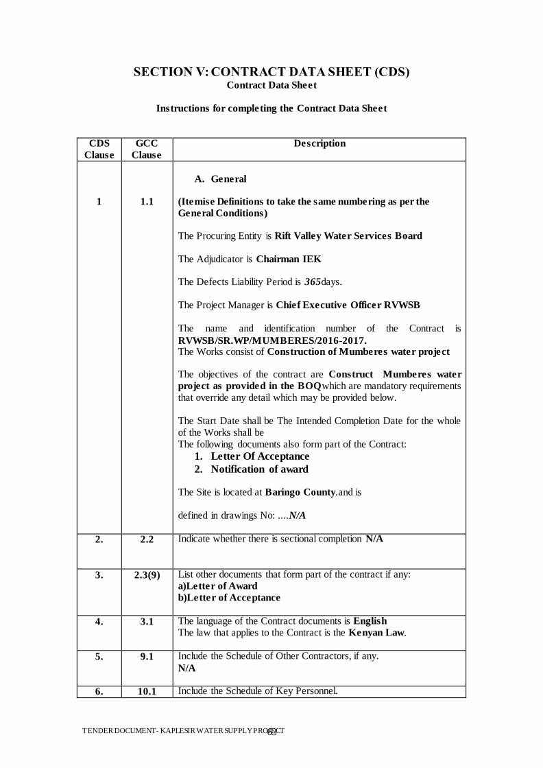
TENDER DOCUMENT- KAPLESIR WATER SUPPLY PROJECT 63
SECTION V: CONTRACT DATA SHEET (CDS) Contract Data Sheet
Instructions for completing the Contract Data Sheet
CDS
Clause
GCC
Clause
Description
1
1.1
A. General
(Itemise Definitions to take the same numbering as per the
General Conditions)
The Procuring Entity is Rift Valley Water Services Board The Adjudicator is Chairman IEK The Defects Liability Period is 365days. The Project Manager is Chief Executive Officer RVWSB The name and identification number of the Contract is
RVWSB/SR.WP/MUMBERES/2016-2017. The Works consist of Construction of Mumberes water project The objectives of the contract are Construct Mumberes water
project as provided in the BOQwhich are mandatory requirements that override any detail which may be provided below. The Start Date shall be The Intended Completion Date for the whole of the Works shall be The following documents also form part of the Contract:
1. Letter Of Acceptance
2. Notification of award The Site is located at Baringo County.and is defined in drawings No: ....N/A
2. 2.2 Indicate whether there is sectional completion N/A
3. 2.3(9) List other documents that form part of the contract if any: a)Letter of Award
b)Letter of Acceptance
4. 3.1 The language of the Contract documents is English The law that applies to the Contract is the Kenyan Law.
5. 9.1 Include the Schedule of Other Contractors, if any.
N/A
6. 10.1 Include the Schedule of Key Personnel.
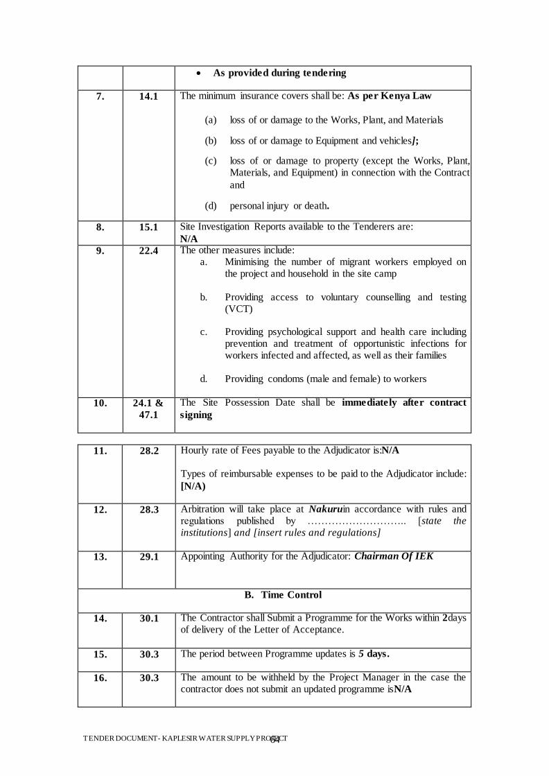
TENDER DOCUMENT- KAPLESIR WATER SUPPLY PROJECT 64
As provided during tendering
7. 14.1 The minimum insurance covers shall be: As per Kenya Law
(a) loss of or damage to the Works, Plant, and Materials
(b) loss of or damage to Equipment and vehicles];
(c) loss of or damage to property (except the Works, Plant, Materials, and Equipment) in connection with the Contract
and
(d) personal injury or death.
8. 15.1 Site Investigation Reports available to the Tenderers are:
N/A 9. 22.4 The other measures include:
a. Minimising the number of migrant workers employed on the project and household in the site camp
b. Providing access to voluntary counselling and testing
(VCT)
c. Providing psychological support and health care including prevention and treatment of opportunistic infections for workers infected and affected, as well as their families
d. Providing condoms (male and female) to workers
10. 24.1 &
47.1
The Site Possession Date shall be immediately after contract
signing
11. 28.2 Hourly rate of Fees payable to the Adjudicator is:N/A Types of reimbursable expenses to be paid to the Adjudicator include:
[N/A)
12. 28.3 Arbitration will take place at Nakuruin accordance with rules and regulations published by ……………………….. [state the institutions] and [insert rules and regulations]
13. 29.1 Appointing Authority for the Adjudicator: Chairman Of IEK
B. Time Control
14. 30.1 The Contractor shall Submit a Programme for the Works within 2days of delivery of the Letter of Acceptance.
15. 30.3 The period between Programme updates is 5 days.
16. 30.3 The amount to be withheld by the Project Manager in the case the contractor does not submit an updated programme isN/A
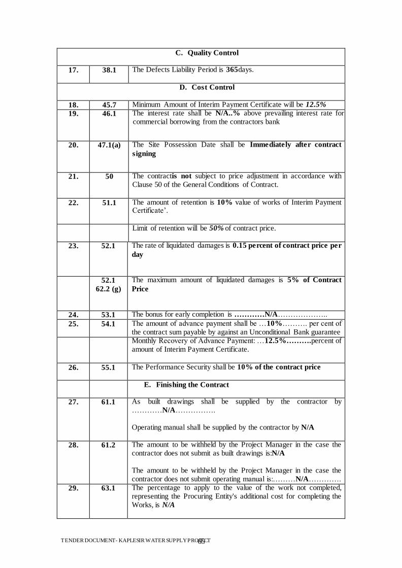
TENDER DOCUMENT- KAPLESIR WATER SUPPLY PROJECT 65
C. Quality Control
17. 38.1 The Defects Liability Period is 365days.
D. Cost Control
18. 45.7 Minimum Amount of Interim Payment Certificate will be 12.5%
19. 46.1 The interest rate shall be N/A..% above prevailing interest rate for commercial borrowing from the contractors bank
20. 47.1(a) The Site Possession Date shall be Immediately after contract
signing
21. 50 The contractis not subject to price adjustment in accordance with Clause 50 of the General Conditions of Contract.
22. 51.1 The amount of retention is 10% value of works of Interim Payment Certificate‟.
Limit of retention will be 50% of contract price.
23. 52.1 The rate of liquidated damages is 0.15 percent of contract price per
day
52.1
62.2 (g)
The maximum amount of liquidated damages is 5% of Contract
Price
24. 53.1 The bonus for early completion is …………N/A………………..
25. 54.1 The amount of advance payment shall be …10%………. per cent of the contract sum payable by against an Unconditional Bank guarantee
Monthly Recovery of Advance Payment: …12.5%……….percent of amount of Interim Payment Certificate.
26. 55.1 The Performance Security shall be 10% of the contract price
E. Finishing the Contract
27. 61.1 As built drawings shall be supplied by the contractor by …………N/A……………. Operating manual shall be supplied by the contractor by N/A
28. 61.2 The amount to be withheld by the Project Manager in the case the contractor does not submit as built drawings is:N/A
The amount to be withheld by the Project Manager in the case the contractor does not submit operating manual is:………N/A………….
29. 63.1 The percentage to apply to the value of the work not completed, representing the Procuring Entity's additional cost for completing the Works, is N/A

TENDER DOCUMENT- KAPLESIR WATER SUPPLY PROJECT 66

TENDER DOCUMENT- KAPLESIR WATER SUPPLY PROJECT 67
SECTION VI: TECHNICAL SPECIFICATIONS
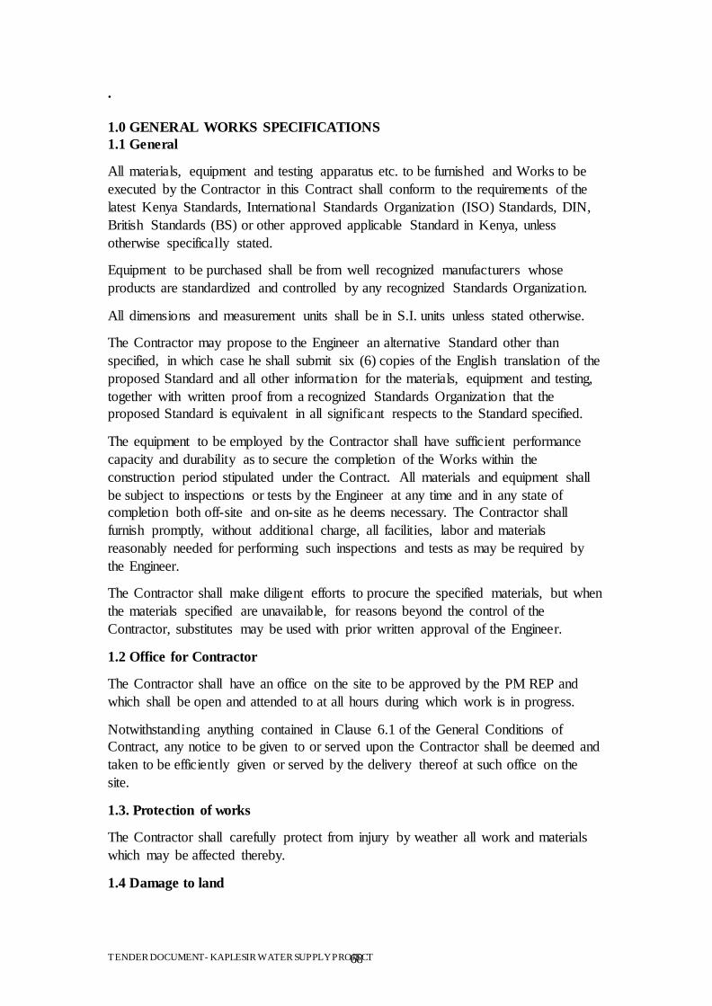
TENDER DOCUMENT- KAPLESIR WATER SUPPLY PROJECT 68
.
1.0 GENERAL WORKS SPECIFICATIONS
1.1 General
All materials, equipment and testing apparatus etc. to be furnished and Works to be
executed by the Contractor in this Contract shall conform to the requirements of the
latest Kenya Standards, International Standards Organization (ISO) Standards, DIN,
British Standards (BS) or other approved applicable Standard in Kenya, unless
otherwise specifically stated.
Equipment to be purchased shall be from well recognized manufacturers whose
products are standardized and controlled by any recognized Standards Organization.
All dimensions and measurement units shall be in S.I. units unless stated otherwise.
The Contractor may propose to the Engineer an alternative Standard other than
specified, in which case he shall submit six (6) copies of the English translation of the
proposed Standard and all other information for the materials, equipment and testing,
together with written proof from a recognized Standards Organization that the
proposed Standard is equivalent in all significant respects to the Standard specified.
The equipment to be employed by the Contractor shall have sufficient performance
capacity and durability as to secure the completion of the Works within the
construction period stipulated under the Contract. All materials and equipment shall
be subject to inspections or tests by the Engineer at any time and in any state of
completion both off-site and on-site as he deems necessary. The Contractor shall
furnish promptly, without additional charge, all facilities, labor and materials
reasonably needed for performing such inspections and tests as may be required by
the Engineer.
The Contractor shall make diligent efforts to procure the specified materials, but when
the materials specified are unavailable, for reasons beyond the control of the
Contractor, substitutes may be used with prior written approval of the Engineer.
1.2 Office for Contractor
The Contractor shall have an office on the site to be approved by the PM REP and
which shall be open and attended to at all hours during which work is in progress.
Notwithstanding anything contained in Clause 6.1 of the General Conditions of
Contract, any notice to be given to or served upon the Contractor shall be deemed and
taken to be efficiently given or served by the delivery thereof at such office on the
site.
1.3. Protection of works
The Contractor shall carefully protect from injury by weather all work and materials
which may be affected thereby.
1.4 Damage to land
TENDER DOCUMENT- KAPLESIR WATER SUPPLY PROJECT 69
Except where specified for the proper execution of the Works, the Contractor shall not
interfere with any fence, hedge, tree, land or crops within, upon or forming the
boundary of the site or elsewhere. In the event of such interference, the Contractor
shall make good to the satisfaction of the owner and the Engineer and shall pay to the
owner such damages as the Engineer may determine.
1.5 Rivers and drains
The Contractor shall at all times maintain the free flow of rivers and drains and
prevent excavated material from the Works from being deposited in them.
1.6 Services
Before commencing Works which include excavation or ground levelling by manual
or mechanical excavation the Contractor shall at his own expenses ascertain in writing
from Telkom Kenya, Kenya Power & Lighting Co. Ltd. and all other Public Bodies,
Companies and persons who may be affected, the position and depth of their
respective ducts, cables, mains, pipes, or other appurtenances. He shall thereupon
search for and locate such services.
The Contractor shall at his own expense arrange to have effectually propped,
protected, underpinned, altered, diverted, restored and made as may be necessary, all
water courses, pipes, cables or ducts, poles or wires or their appurtenances disturbed
or damaged during the progress of the Works, or in consequence thereof.
Except that such services as require to be removed or altered by virtue of the layout of
the permanent work and not the manner in which the work is carried out, shall be so
removed or altered at the direction and at the expense of the Employer.
The Contractor shall be liable for the cost of repairs to any services damaged as a
result of carrying out the Works and execution of these Works.
1.7 Privately owned or public services
If any privately owned or public services passing through the site will be affected by
the Works, the Contractor shall provide at his own expense a satisfactory alternative
service in full working order to the satisfaction of the owner of the services and the
PM REP, before the cutting of the existing service. Any damage to private or public
services shall be made good by the Contractor at his cost.
In case the remedial work is not executed promptly by the Contractor, the PM REP
may make alternative arrangements for the execution of the work and debit the costs
to the Contractor.
1.8Water supply
The Contractor shall provide for all purposes of the work, an adequate supply of water
from a suitable source or sources approved by the PM REP. He must pay the water
charges, if any, and make arrangements for supply, transport and distribution.
1.9 Additional land
TENDER DOCUMENT- KAPLESIR WATER SUPPLY PROJECT 70
The Contractor shall select and arrange at his own expenses for any temporary
occupation of land outside the site which he requires for the efficient execution of the
Works. The Contractor must comply fully with all By-laws and Regulations currently
in force in the area.
1.10 Use of heavy plant
In the event of the Contractor desiring to use heavy machinery or plant, he shall first
satisfy the Engineer that they will be of such size and used in such a manner as not to
cause any disturbance or damage in particular to water, electricity, Post Office or
other mains, cables and connections or to sewers, culverts etc. or interfere with the
line or position of any overhead wires and cables of any sort, telegraph poles, power
poles etc.
The Contractor will be held liable for any such damage or disturbance and shall pay
the full costs of any reinstatement, relaying, repairing or refixing as may be required,
as agreed between the Engineer and the owner affected.
1.11 Provision of instruments and labour
The Contractor shall provide at his own expenses all instruments, materials, tools and
other things which the Project Manager considers necessary for his proper supervision
of the Works and shall maintain the same in good order. He shall also provide
materials, an experienced Surveyor and labour for attendance on the PM REP and his
representatives in carrying out operations connected with the supervision of the
Works. All charges arising out of such services shall be deemed to be included in his
rates in the Bill of Quantities.
1.12 Access to sites
The Contractor shall construct and maintain all temporary accesses required for the
execution of the Works. Access roads shall be constructed and maintained.The cost
of all these Works shall be deemed to be covered by rates and prices quoted by the
Contractor.
1.13 Pollution
The Contractor shall ensure that during the course of his operations no pollution of the
atmosphere, rivers, reservoir catchment areas or groundwater is allowed to take place.
1.14 Tree protection
Trees within the permanent and temporary easement are the property of owners.
Specific trees will be identified by the Engineer, prior to construction, and the
Contractor shall neither remove nor cut their roots unless otherwise directed by the
PM REP. If the roots of such trees appear within the trench areas, the Contractor shall
handle the roots with maximum care so that no portion of the roots will be damaged.
During the excavation of the trench, the exposed roots may be removed to a position
TENDER DOCUMENT- KAPLESIR WATER SUPPLY PROJECT 71
that will not damage the roots and will not interfere with the pipe laying. During the
construction, the roots shall be thoroughly protected by appropriate cover and wetted
as directed. After the pipes are laid, the moved roots shall be placed back to the
original locations and backfilled carefully by selected soft soil which can support
vegetation.
1.15 Watching, fencing and lighting
The Contractor shall arrange to employ watchmen to guard the Works both during the
day and night from the commencement of the Works until the substantial completion
of the Works.
Any excavation or other obstruction likely to cause injury or damage to any person or
domestic animals must be fenced off as directed by the Engineer.
1.16 Tips
The Contractor shall be responsible for provision of all tips, at his own expense, for
disposal of all spoil or other rubbish collected during the construction of the Works.
Any surplus excavated material not required shall also be carted away to these tips.
The site of the tips must be approved by the Engineer.
1.17 Tropicalization
In choosing materials and their finishes, due regard shall be given to the tropical
conditions of the site to which they will be subjected. The Contractor shall submit
details of his practices which have proven satisfactory and which he recommends for
application on the parts of the Works which may be affected by the tropical
conditions.
1.18 Progress meetings
Throughout the project period, progress meetings will be held to discuss the progress
of the work, schedule for the ensuing month, methods of construction, procurement,
transportation, labours, etc. These meetings can be called at any time intervals at the
request of the Contractor or as directed by the Project Manager.
1.19 Inspection by Engineer during defects liability period
The Engineer will give the Contractor due notice of his intention to carry out
inspection during the Defects Liability Period and the Contractor shall upon receipt of
such notice arrange for a responsible representative to be present at the times and
dates named by the PM REP. This representative shall render all necessary assistance
and take notice of all matters and things to which his attention is directed by the
Engineer.
1.20 Submission of samples
Before incorporating in the finished work any materials or articles which he supplies
under the terms of the Contract, the Contractor shall submit to the PM‟s
Representative for his approval a sample of each respective material or article, and
such samples shall be delivered to and kept at his office for reference. All the
TENDER DOCUMENT- KAPLESIR WATER SUPPLY PROJECT 72
respective kinds of materials and articles used in and upon the Works, shall be at least
equal in quality to the approved samples. Each and every sample shall be a fair
average of the bulk material or of the article which it represents. The Engineer‟s
Representative may decide the method by which each sample to be taken from the
bulk material shall be obtained.
1.21 Responsibility for ordering materials and manufactured articles and
samples for testing
The responsibility for so ordering and delivering materials and manufactured articles
and samples that they may be tested sufficiently far in advance of the work as not to
delay it, shall rest upon the Contractor, and he shall not be entitled to any time credit
for delay occasioned by his neglect to order sufficiently well in advance or to effect
payment of any costs he may incur as a result thereof.
With regard to any item in the Bill of Quantities which is the subject of a P.C. Sum,
the Contractor shall notify the Engineer of his requirements as early as possible
leaving ample time for the Engineer to make any necessary arrangements so that no
delay occurs in the progress of the work.
1.22 Tests of materials and manufactured articles before use
Any or all of the materials and manufactured articles supplied by the Contractor for
use on any of the Works throughout this Contract shall be subject in advance to tests
as may be specified in the relevant Standard Specification as may from time to time
be deemed necessary by the Engineer. Samples of all such materials and
manufactured articles, together with all the necessary labor, materials, plant and
apparatus for sampling and for carrying out of tests on the site on all such materials
and manufactured articles shall be supplied by the Contractor at his own expenses.
The cost of special tests ordered by the Engineer to be carried out by an independent
person at a place other than the site or place of manufacture or fabrication shall be
borne by the Contractor.
1.23 Rejected materials
Should any material or manufactured articles be brought on to the site of the Works
which are in the judgment of the Engineer unsound or of inferior quality or in any
way unsuited for the work in which it is proposed to employ them, such materials or
manufactured articles shall not be used upon the Works but shall be branded if, in the
opinion of the Engineer, this is necessary and shall forthwith be removed from the site
of the Works, all at the Contractor‟s expense and in each case as the Engineer shall
direct.
1.24 Quality of materials and workmanship
The materials and workmanship shall be of the best of their respective kinds and shall
be to the approval of the Engineer. In the reading of this Specification the words “to
the approval of the Engineer” shall be deemed to be included in the description of all
materials incorporated in the Works, whether manufactured or natural and in the
description of all operations for the due execution of the Works.
TENDER DOCUMENT- KAPLESIR WATER SUPPLY PROJECT 73
1.25 Construction program
The Contractor shall submit to the PM REP for approval, a revision of the
Construction Program attached in four (4) copies and after approval to the Employer
in two (2) copies in the following manner:
(1) Within seven (7) days after receiving the Letter of Acceptance, the Contractor
shall submit to the Engineer for approval, a detailed Program based on the key date
stated hereinafter or other dates which are given in the Letter of Acceptance in the
form of a Critical Path Method (hereinafter referred to as CPM Network) showing the
order of procedure in which he proposes to carry out the Works including design,
manufacture, delivery to the site, transport, storage, survey, construction,
commissioning and maintenance. This Program shall indicate clearly all activities
and its duration along with the earliest and the latest event, times and the first and last
dates of the submission of the Drawings and each date of shop inspection by the
Engineer for the section or portion of the Works.
The Program so prepared shall be rearranged in the form of a Time Bar-chart
Schedule of which size shall be 841mm x 594mm (A-1 size). This Time Bar-chart
Schedule shall be submitted to the Engineer together with the CPM Network.
(2) The CPM Network shall be in accordance with commonly accepted practices and
shall show graphically the chain of activities / sub-activities and their sequential
relationship with each other from the start of construction to the completion of the
Contract. The Time Bar-chart Schedule shown in weeks shall list all main activities
and its applicable sub-activities.
(3) In preparing the CPM Network and the Time Bar-chart Schedule the Contractor
shall make due allowances for possible delays. Under no circumstances shall the
CPM Network or the Time Bar-chart Schedule show a completion in excess of the
“Time for Completion” stated in the Form of Tender.
(4) The Program once approved by the Engineer shall thereafter be referred to as the
Contractual Program. The Engineer‟s approval of such Program shall not relieve the
Contractor of any of his duties or responsibilities under the Contract.
1.26 Possession and use of the Site
The Contractor shall request possession of the Site from the Project Manager‟s Rep
when required and in accordance with his program of Works. The CLIENT shall grant
possession in accordance with Sub-Clause 2.1 of the Conditions of Contract.
When the Contractor is given possession of the Site he shall be given authority to
carry out the Works instructed by the Project Manager‟s Rep under the Contract.
The Contractor shall not enter the Site for additional investigations or to execute the
Works until he has been granted possession. If the Contractor requires to enter the
Site prior to being granted possession for other reasons and the Project Manager‟s
Rep agrees, he shall demonstrate that he has the necessary insurances and has
arranged appropriate safety measures.
TENDER DOCUMENT- KAPLESIR WATER SUPPLY PROJECT 74
During possession of the Site, or portion of the Site, the Contractor shall be
responsible for providing lighting, protection and other measures to make the
temporary works, material storage, excavations, partially finished works, etc. safe for
the public and road use.
The CLIENT will arrange for the above and shall make the Site available to the
Contractor upon request.
1.27 Site Tidiness
The Contractor shall be responsible for the proper tidiness of the Site and Works and
remove rubbish and waste promptly from the Site. All materials, plant and equipment
shall also be stored or positioned in a tidy manner.
1.28 Entry on to the Site
Prior to the commencement of operations, the Project Manager‟s Rep shall supply to
the Contractor the names and addresses of relevant owners and occupiers. The
Contractor shall notify the Project Manager‟s Rep in writing 56 days in advance of his
intention to start work within each area of ownership or occupation.
The Contractor shall keep records of the dates of his entry on to and departure from
all property and lands of each owner and occupier, together with the dates of the
erection and removal of all enclosures, and shall furnish copies of these records when
required by the Project Manager‟s Rep. He shall keep, and furnish, copies of similar
records in respect of roads, footpaths and thoroughfares.
The Contractor shall not enter or use any part of the Site for any purpose not
connected with the Works. Where the Contractor requires any facilities or temporary
occupation of land (such as changes to site boundaries or access routes) he shall make
his own arrangements with the land owners/occupiers or local authority as
appropriate.
Any special conditions concerning entry to the Site are given elsewhere in the
Contract.
1.29 Site Compound
The Contractor shall find his own site or sites for setting up one or more compounds
in which to locate his offices, workshops, stores, plant etc. The sites shall be close to
the Project Manager‟s Rep‟s office and the Site laboratory.
On completion of the relevant section of the Works the Contractor shall remove all his
offices, workshops, stores, plant, fencing, hard standing etc., clean up the site and
carry out other works to return the site to its original condition.
The Contractor shall also locate his own areas for collection and disposal of waste and
unwanted materials, complying with local regulations and procedures for transport
and disposal.
The Contractor shall obtain all necessary approvals of local authorities and others for
its site compound at its own cost.

TENDER DOCUMENT- KAPLESIR WATER SUPPLY PROJECT 75
1.30 Documents to be submitted to the Project Manager‘s Rep
Prior to commencement of the Works the Contractor shall supply a Works Program to
the Project Manager‟s Rep for approval.
The Works Program to be provided under the Conditions of Contract shall be
submitted in the form of a Time – Location Chart clearly indicating the phasing of all
work. Plant and labor resource teams shall be listed for all operations.
The program shall be updated following any major variations or extension of time
given, and when any critical operation has fallen behind its planned program by more
than 10 per cent, and in any case at 91 day intervals. On a regular base, the Contractor
shall supply the following documents to the Project Manager‟s Rep:
Cash Flow (monthly); List of Labor and Plant (monthly).
The submission will show cash flow up to the end of the Contract. The Contractor
shall also submit to the Project Manager‟s Rep at the end of each calendar month, or
at such other times as may be agreed, detailed schedules and reports on plant and
labor on Site, divided into categories, and show separately the Contractor‟s and each
sub-contractor‟s labor and plant. As far as the plant is concerned, the condition of
each item shall be indicated in the schedules.
Construction method statements shall be prepared for the principal elements of the
Works and shall be submitted to the Project Manager‟s Rep for review at least 28
days prior to the programed activity commencement.
Construction method statements shall make due allowance for all requirements and
restrictions imposed by the Contract. Each method statement shall comprise a step by
step schedule of specific operations or activities with description, date, times and
duration of each step. The statements shall be supported by sketches, diagrams or
other supportive detail as necessary to enable a clear understanding of the method and
significance of each step of work or operation.
Construction method statements shall include, but not be limited to, the following
topics as relevant to the particular operation:
the method of working;
temporary works details;
labour resources to be used;
construction equipment to be used;
safety measures; and
pedestrian, light vehicular and emergency access.
The Contractor shall prepare and submit for the Project Manager‟sRep‟s approval all
bar bending schedules and all drawings of temporary work.
1.31 Survey
1.31.1 Survey of roads, properties, lands and crops
Where appropriate, the Project Manager‟s Rep shall arrange for surveys to be carried
out, in conjunction with the Contractor and the Road Authority, owners or occupiers,

TENDER DOCUMENT- KAPLESIR WATER SUPPLY PROJECT 76
of the condition of roads, drainage structures, properties, lands and crops which may
be affected by the Works.
1.31.2 Level Datum and Dimensions
All levels shall be referred to the National Datum and the Contractor shall obtain in
writing from the Project Manager‟s Rep the location and value of the permanent
benchmarks to be used to control the works. Before the commencement of
construction work the Contractor shall establish at each site in a position to the
approval of the Manager‟s Rep, a steel datum peg that shall be securely concreted in.
The level of this peg shall be established and agreed with the Project Manager‟s Rep
and all levels used in the construction of the Works shall be referred to this
established datum. The correctness of this established datum shall be checked at
regular intervals during the construction period and agreed with the Engineer.
The levels of the ground and the levels and dimensions of existing features
shown on the Drawings are believed, but are not guaranteed, to be correct. Wherever
dimensions or levels are marked on the Drawings such dimensions or levels shall take
precedence over dimensions scaled from the Drawings. Where no dimensions or
levels are shown on the Drawings, instructions shall be obtained from the Project
Manager‟s Rep.
In the event of discrepancies between the Drawings and the Specification, the
Drawings shall take precedence over the Specification.
1.31.3 Levels and reference points
The Contractor shall supply to the Project Manager‟s Rep details of the value and
location of the temporary datum and reference points which he proposes to use.
The Contractor shall satisfy himself that the existing ground levels and the levels and
locations of structures as indicated in the Contract are correct. Should the Contractor
wish to dispute any levels he shall submit to the Project Manager‟s Rep a schedule of
the position of the levels considered to be in error and a set of revised levels.
1.31.4 Setting Out of the Works
It shall be the Contractor‟s responsibility to obtain from the Project Manager‟s Rep
before commencing the work co-ordinates and levels of setting out points, which have
already been established by the Project Manager‟s Rep. The Contractor shall use these
to establish additional temporary bench marks as necessary throughout the project
area. These shall be of a form approved by the Project Manager‟s Rep and shall be
maintained until the completion of works.
The Contractor shall be responsible for the setting out of the works, in
accordance with the Conditions of Contract. All dimensions and levels shown on the
drawings referred to in any document forming part of the Contract shall be verified by
the Contractor on site. He shall be responsible for pointing out promptly any
discrepancies or error is such dimensions or levels. The Contractor shall prepare
detailed setting out drawings and data sheets as necessary and submit them to the
Project Manager‟s Rep for approval. Any modification of these drawings or data

TENDER DOCUMENT- KAPLESIR WATER SUPPLY PROJECT 77
sheets required by the Project Manager‟s Rep shall be made by the Contractor and
resubmitted for final approval.
1.32 Temporary fencing/ security of site
The Contractor shall be responsible for ensuring that the Site is adequately fenced.
The Contractor shall do this work prior to starting work on the relevant portion of the
Site. The Contractor shall regularly inspect and maintain all such fencing, any defects
being made good without delay.
Access shall be provided in temporary/Site fencing as necessary for the use of the
occupiers of adjacent lands. Temporary site fencing shall remain in position until
either it is replaced by permanent fencing or the Works are sufficiently completed to
enable that portion of the Site to be brought into use. The type and height of
temporary fencing shall be to the Project Manager‟s Rep‟s satisfaction where not
stated elsewhere in the Contract.
Where required by the Contract the Contractor shall be responsible for making the
Site secure with lockable access gates and security lighting to suit local conditions.
1.33 Interference with land interests
The Contractor shall confine his constructional operations within the Site, or such
other areas of land as may be negotiated, and shall instruct his employees, and those
of his sub-contractors, not to trespass.
Subject to any unavoidable disturbance that may be necessitated by the execution of
the Contract, the Contractor shall not interfere with any sporting, fishing or other
rights that may be enjoyed on or near the site.
Before exercising any right negotiated by him in connection with way leaves or
accommodation outside the site, the Contractor shall notify the Project Manager‟s Rep
in writing of such arrangements.
Normally on site living accommodation will not be permitted but where it is
unavoidable, this will be detailed in the Contract.
1.34 Interference with access to properties and apparatus
Before interfering with access to any property, the Contractor shall provide alternative
arrangements. The Contractor shall notify the Project Manager‟s Rep and the relevant
occupiers in writing 14 days in advance of any such interference and shall confirm to
the Project Manager‟s Rep that alternative arrangements have been agreed.
The Contractor shall take particular account the access and service requirements of
those with special needs. Special needs are defined as those needs related to health
and mobility of individuals affected and individuals concerned with the health of
others.
The Contractor shall not unreasonably obstruct access to any manhole or other surface
cover outside normal working hours.
1.35 Procedure for complaints and claims for damage
TENDER DOCUMENT- KAPLESIR WATER SUPPLY PROJECT 78
The Contractor shall notify the Project Manager‟s Rep in writing immediately
following any damage or injury arising out of the execution of the Works.
Details of all claims or warnings of intended claims which the Contractor may receive
from third parties shall be notified without delay to the Project Manager‟s Rep, who
shall likewise pass to the Contractor any such claims or warnings which may be
submitted directly to the Project Manager‟s Rep or CLIENT.
The Contractor shall deal promptly with any complaints, claims, damage or injury by
owners or occupiers.
1.36 Protection against damage
The Contractor shall take all necessary precautions to avoid causing any unwarranted
damage to roads, lands, properties, trees and other features during the currency of the
Contract.
Where any portion of the Works is close to, across, or under any existing apparatus of
Utility Companies, the Road Authority or other parties, the Contractor shall
temporarily support and work round, under or adjacent to all apparatus in a manner
designed to avoid damage, leakage or danger, and to ensure uninterrupted operation.
Should any leakages or damage be discovered, the Contractor shall at once notify the
Project Manager‟s Rep and the Utility Company, Road Authority or owner concerned,
as appropriate, and the Contractor shall afford every facility for the immediate repair
or replacement of the apparatus affected. The Contractor shall fully reinstate at his
expense and to the Project Manager‟s Rep‟s satisfaction any damage caused by any of
his operations.
Damage includes all actions that would lead to environmental damage such as tipping
of waste, fuel or oil and destruction by plant and equipment.
The Contractor shall protect all underground and above ground existing structures
from damage, whether or not they lie within the limits of the easements obtained by
the CLIENT. Where such existing walls, fences, gates, sheds, buildings, or any other
structures must be removed in order to carry out the construction properly, they shall
be restored to their original condition to the satisfaction of the property owner,
occupier and Project Manager‟s Rep. The Project Manager‟s Rep shall be notified of
any damage made to structures and repairs or replacements shall be made before
backfilling takes place. The Contractor shall remove and replace such small
miscellaneous structures as fences, mailboxes, and signposts without additional
compensation from the CLIENT. These structures shall be replaced in a condition as
good as their original condition.
If existing structures are encountered which will prevent the construction of the
Works as designed, the Contractor shall notify the Project Manager‟s Rep of his
proposed changes and make such reasonable modifications as are necessary to the
satisfaction of the Project Manager‟s Rep.
1.37 Protection of agricultural land
TENDER DOCUMENT- KAPLESIR WATER SUPPLY PROJECT 79
The Contractor shall submit details to the Project Manager‟s Rep of all herbicides
and pesticides proposed for approval. Specific requirements to prevent the spread of
animal and plant diseases (if any) are given in the Contract.
1.38 Works affecting watercourses
The Contractor shall notify the Project Manager‟s Rep in writing 14 days in advance
of his intention to start any part of the Works affecting a watercourse (whether
running with water or not), canal, lake, reservoir, borehole or aquifer.
The Contractor shall be responsible for maintaining watercourses within the Site in
effective working condition at all times.
The Contractor shall take all practicable measures to prevent the deposition of silt or
other material in, and the pollution of, or damage to, any existing watercourse, canal,
lake, reservoir, borehole or aquifer, arising from his operations and acts of vandalism.
The Contractor shall obtain approval for all temporary discharges, crossings or
diversions to watercourses. National legal requirements (if any) and those specific to
the Project and are detailed in the Contract.
Generally all liquid/fuel storage tanks shall be located in a sealed protective retaining
bund capable of holding at least 110% of the tank volume with a freeboard of 200mm.
Filling/discharge pipe work shall be positioned to contain spillage in the bund and all
valves shall be lockable.
1.39 Dealing with water
The Contractor shall bear all risks associated with water, whether from the main river,
local water courses, irrigation channels, underground springs, rainfall or any other
sources or cause. The Contractor shall take measures, carry out any operation and
provide and use all necessary plant, appliances, pumps, and the like for dealing with
flowing or standing water within the Site. The Contractor shall be responsible for
pumping all water from excavations.
1.40 Hygiene
Before any person is engaged on work involving possible contact with potable water,
he shall be notified of the need for personal hygiene and the dangers of
contamination, shall complete a medical questionnaire provided by the CLIENT and,
where there is a need, shall be tested to indicate that he is not a carrier of any
waterborne disease. The Contractor shall notify the Project Manager‟s Rep of any
person who has been certified by a doctor as suffering from an illness associated with
looseness of the bowels and no such person shall be employed on such work until the
CLIENT's medical adviser is satisfied that it is safe for him to be employed.
Where there is a doubt concerning a person's suitability to be employed on the Works,
that person will be required to complete a medical examination certifying that he
is clear of illness associated with any waterborne disease.
Where the Works are intended for the purpose of supplying potable water to the
public, every precaution must be taken to avoid contamination of the Works. For this
TENDER DOCUMENT- KAPLESIR WATER SUPPLY PROJECT 80
reason, any workman fouling any site or its vicinity shall be removed from the
Works and shall not thereafter be employed upon the Works without the
permission of the Project Manager‟s Rep .
The Contractor shall provide sufficient chemical-type toilets at each working location,
of suitable type, and maintain the facility in a sanitary condition at all times.
Chemical-type toilets shall be of adequate construction so that no unsanitary
contamination of the area can result from their
use. Upon completion of that part of the Works, sanitary facilities shall be removed
and the areas restored to their original condition.
1.41 Utilities relocation and protection
The Contractor shall be responsible for identifying the location and nature of all
services on the Site, liaising with utilities and other organizations or bodies whose
services may be affected by the Works and obtaining the necessary permits and
approvals for design and construction of the Works. The necessary approval periods
shall be allowed for in the Contractor‟s scheduling program.
Notwithstanding any approvals, before excavation commences the Contractor shall
ascertain the accurate location of existing services using safe methods of pipe
location, cable detection or hand digging of trial holes as appropriate. If any
underground service is encountered unexpectedly the Contractor shall notify the
Project Manager‟s Rep and owner of the service without delay. Notwithstanding any
services information supplied to the Contractor the responsibility to locate all services
and prevent any damage to existing services shall rest with the Contractor.
The Contractor shall be responsible for all works as may be required in the inter-
relation with existing utilities and services, such as the realignment, adjustment,
disconnection, relaying and reconnection, for all and any delay occasioned thereby
and making payment to the relevant statutory bodies for utility services.
The Contractor shall ensure that all utility service providers, including the CLIENT,
whose equipment already traverses the Site can gain access to that equipment to
inspect, repair and renew the same without restriction.
The Contractor shall record the position of all located existing services on the general
arrangement drawings a copy of which shall be made available by the Contractor to
the Project Manager‟s Rep. If any service is found to exist but is not as indicated in
the Contract then the Contractor shall at once give written notification to the Project
Manager‟s Rep. No warranty is given as to the accuracy or completeness of the
information on existing services included in the Contract.
It shall be the Contractor's responsibility to ensure proper backfilling, appropriate to
the section of the site, of any excavation made in the work area by any Utility
Company, made necessary by the Contractor's operations.
The Contractor shall possess sufficient serviceable pipe/cable detectors for locating
buried pipes and cables and appropriate staff competent in their use. Each detector
shall be operated in accordance with the manufacturer's instructions.
TENDER DOCUMENT- KAPLESIR WATER SUPPLY PROJECT 81
Paint used for temporary marking of services shall be non-permanent and shall either
weather away naturally or be capable of being washed away using water and a stiff
brush.
The Contractor shall comply with any relevant local or National Utility regulations
indicated in the Contract.
1.42 Traffic management
Throughout the execution of the Works and the remedying of any defects therein, the
Contractor shall:
have full regard for the safety of all persons on the Site and shall keep the Site (so far
as the same is under his control) as well as the Works (so far as the same are not
completed or occupied by the CLIENT) in an appropriate state to avoid any danger to
all persons whether or not they are authorized to be on the Site; and provide and
maintain, at his own cost, all lights, barriers and warning signs, when and where
necessary or when required by the Project Manager‟s Rep for the protection of the
Works or for the safety and convenience of the public or others.
The Contractor shall not commence any work that affects the public roads until all
traffic safety measures necessitated by the work are fully operational.
The traffic signs, road markings, lamps, barriers and traffic control signals shall be in
accordance with the requirements current at the date of the execution of the work.
The Contractor shall keep clean and readable at all times all traffic signs, road
markings, lamps, barriers and traffic control signals and he shall position, re-position,
cover or remove them as necessitated by the progress of the Works.
Roads, accesses, rights of way, etc. which are being used by construction traffic shall
at all times be kept clean of all dirt, mud and material dropped from vehicles or from
tyres arising from such use. The Contractor shall provide, maintain and use suitable
equipment for this purpose.
In carrying out the Works the Contractor shall ensure that all road drains, ditches and
channels are kept clear of any spoil, mud, slurry, or other materials likely to impede
the free flow of water.
Where work is carried out on, or adjacent to a highway open to traffic, the Contractor
shall ensure that vehicles and mobile plant under his control operating frequently or
regularly on or adjacent to that highway in the execution of the Works shall be
painted in a conspicuous color.
The Contractor shall provide, and suitably sign, points of entry to and exit from the
Site, for vehicles and plant engaged on the Works. The Contractor shall ensure that
when any vehicle or item of plant is reversing within the Site on or adjacent to a
highway open to traffic, it does so only under the supervision of a person designated
for the purpose of regulating traffic within the Site who shall be readily
distinguishable from the remainder of the work force.
TENDER DOCUMENT- KAPLESIR WATER SUPPLY PROJECT 82
Where work is carried out on or adjacent to a highway open to traffic, the Contractor
shall ensure that the work force and the site supervisory staff at all times wear high
visibility warning clothing.
1.43 Emergency arrangements
The Contractor shall maintain arrangements whereby he can quickly call out labour
outside normal working hours to carry out any work needed for an emergency
associated with the Works. The Project Manager‟s Rep shall be provided at all times
with a list of addresses and telephone numbers of the Contractor's staff who are
currently responsible for organizing emergency work.
The Contractor shall acquaint himself and his employees with any relevant local
arrangements that are in existence for dealing with emergencies.
1.44 Hazardous substances
No hazardous substances shall be brought on to the Site or used for any purpose
unless the Contractor has previously obtained the written approval of the Project
Manager‟s Rep and has obtained the necessary permits. The Contractor shall obtain
the Project Manager‟s Rep‟s approval in writing prior to storing and locations of any
hazardous substance on the Site.
The Contractor shall comply with Specific local or National codes and laws, for
example, those concerning storage of fuel and flammable substances and explosives.
1.45 Existing structures and underground services
Where, in the course of construction of the Works, any existing foundations, walls,
sewers, drains, pipes, wires, cables, and other structures, places and things are
exposed, or otherwise are affected by the execution of the Contract, they shall be
properly maintained, adequately supported and protected. Expedients to the approval
of the Project Manager‟s Rep shall be adopted, which will prevent inconvenience,
interruption and which will ensure safety and continuity of use, of the above.
1.46 Fire prevention and protection
The Contractor shall perform all work in a fire-safe manner. He shall supply and
maintain on the site adequate fire-fighting equipment. The Contractor shall comply
with all current applicable fire regulations.
1.47 Access by officials and visitors
Authorized clients; or Government; financiers and municipal officials shall at all
times have access to the work wherever it is in preparation or progress, and the
Contractor shall provide proper facilities for such access and for inspection.
Where the Site has conditions requiring access by archaeologists, environmental or
conservation officials, this will be detailed in the Contract.
TENDER DOCUMENT- KAPLESIR WATER SUPPLY PROJECT 83
Where visitor access is required to the site offices, particular care shall be taken to
ensure that this access is safe and adequately signposted.
1.48 Public safety and convenience
The Contractor shall mark all open trenches and other obstructions by approved signs,
fences, barricades, and lights for the safety of the public.
1.49 Street clean-up during construction
The Contractor shall clean all spilled dirt, gravel, or other foreign material caused by
the construction operations from all streets and roads at the conclusion of each day's
operation. Cleaning shall include washing with water, power brushing, and use of
manual labor as necessary to achieve the standard comparable with adjacent streets
unaffected by the works.
The Contractor shall take all reasonable steps to prevent vehicles entering and leaving
the Site depositing mud or other debris on the surface of adjacent roads or footways,
and shall remove expeditiously any materials so deposited. The Contractor shall not
without the agreement of the Project Manager‟s Rep obstruct more than a 100 meter
length of any part of the highway at any one time.
1.50 Access for emergency services
The Contractor shall notify the Fire and Police Services before closing any street or
portion thereof and no closing shall be made without the Project Manager‟sRep‟s
approval. The Fire and Police Services shall be notified when the streets are again
passable for emergency vehicles. The method adopted for construction of the Works
shall minimize interference with Fire and Police Service access and at no time prevent
such access.
The Contractor shall leave his night contact telephone number with the local Police
office whenever construction operations are in progress.
1.51 Tipping facilities and waste materials
No tipping facilities are to be provided by the CLIENT (unless otherwise indicated in
the Contract) and he shall make all arrangements and bear all costs for the disposal of
all surplus excavated material. Unauthorized tipping shall not be permitted.
The removal of waste material from the site must comply with local and National
regulations in respect of carrying and disposal.
1.52 Testing
If the Contractor provides his own testing facilities, the equipment, staff and method
of operation shall be acceptable to the Project Manager‟s Rep, and up to 25% of all
tests conducted by the Contractor shall simultaneously be carried out, on samples of
the same material, by an approved independent testing laboratory. The Project
Manager‟s Rep shall have access to the Contractor's laboratory or the independent
laboratory at all reasonable times.
TENDER DOCUMENT- KAPLESIR WATER SUPPLY PROJECT 84
The Contractor submits all test results without delay. Test results from independent
laboratories shall be copied and sent directly to the Project Manager‟s Rep by the
laboratory.
1.53 Works off-site
When major components of the Works are manufactured off-Site, the Contractor shall
make arrangements to provide an adequate and secure office at or adjacent to the
place of, and during the period of, manufacture and testing. The Contractor shall give
written notice to the Project Manager‟s Rep of the workshops and places where work
is being, or is about to be, carried out from which materials of manufactured articles
are about to be or are being supplied. He shall also give such notice and keep the
Project Manager‟s Rep advised of the times when such materials will be ready to be
inspected, so that such inspection may take place without delaying the delivery of the
materials to the site. Such notices shall be given at such times as will permit the
inspection of the whole of the work at all stages of the processes of manufacture and
not simply when the goods are completed ready for delivery.
At least four weeks prior to the placing of any orders for major components of the
Works the Contractor shall forward to the Project Manager‟s Rep for approval full
and detailed particulars and samples when requested of the materials/ components that
he intends to procure for the Works. All these items shall comply with the
Specification and shall bear necessary approvals for use in Kenya.
1.54 Other contractors
The Contractor is advised that other contractors employed by the CLIENT and
employees of the CLIENT may be working on and around the Site. The Contractor
shall grant access to the Site to any such persons. The Contractor shall liaise with the
CLIENT and shall plan and execute the Works for mutual convenience and ensure
satisfactory progress of the project.
The Contractor shall not interfere in any way with any works, whether the property of
the CLIENT or of a third party and whether or not the position of such works is
indicated to the Contractor, by the Project Manager‟s Rep, except where such
interference is specifically described as part of the Works either in the Contract or by
the Project Manager‟s Rep‟s instruction. The Contractor shall respect and shall ensure
that his employees and his subcontractors respect the construction and finish of works
and articles supplied or installed by others and will be held responsible for any loss or
damage thereto if caused by him.
1.55 Safeguarding the environment
The Contractor shall execute all works and take any measures for environmental
protection and impact mitigation in accordance with the laws in force in Kenya. He
shall obtain all the necessary updated information concerning the NEMA regulations
and obtain all the necessary authorizations and carry out complementary studies
TENDER DOCUMENT- KAPLESIR WATER SUPPLY PROJECT 85
whenever necessary. He shall obtain environmental approvals for all temporary
works.
During the works, including site mobilization and the maintenance period, the
Contractor and his sub- contractors, in compliance with the norms and regulations in
force, shall implement the following mitigation measures:
Reduction of Equipment and Plant noise when working in urban areas and in
proximity to occupied buildings. Control of vibration from plant and equipment in
urban areas and in proximity to buildings and other structures. Optimum location for
crushers, bitumen plants, batching plants and other similar plants, in order to
minimize their adverse impact on the natural and human environments. Enforcement
of an adequate traffic management plan to minimize the disturbance caused by the site
traffic and to safeguard the public and the Contractor‟s labor. Protection of rivers,
lakes, lands in crop and any areas surrounding the Site, against any pollution, which
may originate either from the permanent road works or from other activities related to
the Contractor‟s organization. Control of the method of storage of materials, with
strict observance of the standards and specifications regarding the most sensitive
items such as fuel, bitumen, lubricants, cement, explosive, etc. Protection and
accurate reinstatement at the end of the works of borrow pits, quarries, services and
diversion roads and any other temporary or preparatory work.
Provision and installation of specific equipment and the relevant monitoring of noise,
gas, dust, liquids and other pollutants derived from Site activities. Reduction of the
emission of pollutants when they reach maximum admissible levels, in
accordance with the Kenyan current legislation and norms. Biodegradable materials
shall be carefully buried in locations approved by the Project Manager‟s Rep and the
local environmental Agency in order to prevent any pollution of underground water.
Any other action which might be necessary in accordance with the Project Manager‟s
Rep‟s instructions and, as required by the current Kenyan legislation. (Law No. 137,
dated 30.12.1995 refers particularly). The Contractor shall, at the request of the
Project Manager‟s Rep, carry out whatever environmental measurements are required
to demonstrate that the requirements of this Clause are being respected. The tests shall
be carried out at the locations and times required by the Project Manager‟s Rep, and
the Contractor shall carry out such tests at his own expense with instruments supplied
by him.
1.56 Contractor‘s equipment
Details of all Contractor‟s equipment to be used by the Contractor in the execution of
the Works shall be submitted to the Project Manager‟s Rep prior to its use. If in the
Project Manager‟s Rep‟s opinion circumstances arise where it is reasonable that the
use of the Contractor‟s equipment should be suspended either temporarily or
permanently, the Contractor shall change the method of performing the work affected.
In particular, this will apply where it is impossible or unsafe to excavate except by
hand methods, due to the proximity of, and danger to, existing roads, structures, or
services.
TENDER DOCUMENT- KAPLESIR WATER SUPPLY PROJECT 86
The Contractor shall be deemed to have no cause for claims against the CLIENT on
account of having to carry out the work by another method, nor shall he be deemed to
have cause for claim if any order issued by the Project Manager‟s Rep results in the
Contractor‟s equipment having to stand idle for a period of any duration whatsoever
or having to be removed.
1.57 Accommodation for the contractor
The Contractor shall provide, erect, service and maintain all necessary buildings as
offices, housing or plant/yard/stores for himself, his staff and his employees.
The Contractor shall arrange the supply of electricity, fresh water, telephone,
compressed air and other services as are necessary to his Site establishment and shall
provide, maintain and remove on completion all pipes, cables and fittings which carry
such services to his operations. The Contractor shall provide an adequate supply of
safe drinking water on the Site. All electrical installations forming part of the
Temporary Works shall comply with the current National Regulations.
The Contractor shall make all necessary arrangements for the purchase or rental of
land, for his offices, housing, plant yard, stores, and with the supply of electricity and
water and sewage and waste disposal (including the construction of septic tanks).
All buildings shall comply with the appropriate local or National regulations and the
Contractor shall provide the appropriate Authority with sufficient details of the
establishment so that approval of that Authority can be obtained by the Contractor
prior to construction. The Contractor shall also construct and maintain adequate roads
or paths to all buildings.
All huts, buildings, fixtures and fittings provided under this Clause shall be removed
and the site reinstated at the end of the Contract.
1.58 Clearance of site on completion
A Completion Certificate will not be issued before the Contractor has removed all his
machinery, equipment, plant, waste material from the Site and the Site reinstated to
the satisfaction of the Project Manager‟s Rep .Issuance of Substantial Completion
Certificate is not considered a completion certificate for discharge of contractor duties
until the former is attained.
1.59 Construction permits
The Contractor shall obtain all permits necessary for the construction, occupation and
use of the Works. The Project Manager‟s Rep has no role in assisting the Contractor
in obtaining the necessary permits. The Contractor shall assist the Project Manager‟s
Rep and the CLIENT in obtaining permits that only the CLIENT may obtain.
The Contractor shall allow a realistic timescale for dealing with the third parties
responsible, for permits etc., in his planning and programming of the work.
The Contractor shall comply with all conditions stipulated in any permits granted by
third parties, including conditions stipulated in those permits obtained by the
CLIENT.
TENDER DOCUMENT- KAPLESIR WATER SUPPLY PROJECT 87
1.60 Working hours
Working hour restrictions will apply to the Site including the delivery of materials
and equipment. Details are given in the Contract. Overtime works will be approved
first by the Project Manager‟s Rep.
1.61 Temporary works
The Contractor shall design, arrange, provide and remove at his own cost all
temporary works needed to carry out the Permanent Works. The temporary works
shall include the provision of road diversions where considered necessary. All
temporary works shall be approved by the
Project Manager‟s Rep, but this shall not relieve the Contractor of his responsibility
for their design and adequacy. The Contractor shall obtain all the necessary approvals
from the relevant authorities, service (utility owners), local municipalities and other
third parties for his design of the temporary works where required.
The Contractor shall be responsible for obtaining all approvals and permits for
organizing all necessary land hire for any temporary works such as access roads,
diversion roads, borrow pits, site compounds, material and equipment storage areas,
laboratory facilities and so on. He shall restore the areas affected by these temporary
works either to their original condition or to a condition agreeable to the Project
Manager‟s Rep, or stipulated in approvals.
The Contractor shall design and construct any form of temporary road diversion and
rail or river crossing and shall be responsible for obtaining approvals and clearances
from all land owners and other relevant organizations affected by these temporary
works.
The temporary road diversions shall be designed and constructed using materials and
workmanship that prevent settlement, rutting or distortion of the running surface. The
design of the diversion shall be submitted, to the Project Manager‟s Rep for approval.
The Contractor shall submit details of his scheme to the landowners, river authority
etc. When submitting the design of the diversion to the Project Manager‟s Rep, the
Contractor shall also submit his proposals for traffic management and safety whilst
the diversion is in use and shall obtain approval of such from local authorities.
On completion of the relevant section of the Works for which temporary works have
been provided, the Contractor shall remove such roads, structures and the like and
reinstate the ground on which they had been constructed to its original or to a similar
condition to the satisfaction of the Project Manager‟s Rep.
1.62 Drawings and documents
Subject to the requirements of the Particular Specifications the Contractor shall
prepare shop and Working Drawings necessary to execute the works. The calculations
and Working Drawings shall be submitted to the Project Manager‟s Rep for approval
TENDER DOCUMENT- KAPLESIR WATER SUPPLY PROJECT 88
14 days, or as otherwise specified, prior to commencement of the relevant sections of
the works on site. Should the submission not be acceptable to the Project Manager‟s
Rep, the contractor shall re-submit with such further details and information that the
Project Manager‟s Rep may require until the Project Manager‟s Rep is satisfied. The
relevant section of work cannot be commenced prior to approval. The Contractor‟s
submission for approval shall be sufficient for the Project Manager‟s Rep to be able to
confirm that his proposals conform to the Specification and any relevant Codes and
standards. The submission shall be legible and in English, or with an English
translation. As a minimum it shall include,
Calculations, detailing the applicable recognized Codes or Standards.
Drawings and sketches to clarify the submission.
Details of proprietary materials.
Details of any deviation from the Specification, with explanation.
Confirmation from a suitably qualified person that the submission has been
checked for conformity with the Specification.
Any deviation from the approved submission will require the prior approval of the
Project Manager‟s Rep.
If within 14 days, or otherwise specified period, such approval has not been granted,
other than due to rejection of the submission by the Project Manager‟s Rep , then
approval will be deemed to have been granted. Any such approval, deemed or
otherwise, will not relieve the Contractor of any of his obligations under the Contract.
All dimensions in drawings, calculations and information furnished in connection
with the Contract shall be expressed in metric SI units (Metric SI units: m, kg, N,
kg/cm², °C, watt, bar, etc.).
All drawings shall be sized to designations A1, A2, A3, and A4. Sizes AO and above
shall not be used. Each drawing shall carry the project title, the name of the Project
Manager‟s Rep, the Contractor and the Employer together with the drawing title and
number and other relevant data, in the lower right-hand corner. The Project Manager‟s
Rep‟s approval of the Working Drawings, Contract Records etc. and of the Workshop
test records etc., shall not relieve the Contractor of the obligation to meet the terms of
the Specification and any of the plant which upon delivery to site is found to be
incorrect or unsatisfactory, or which fails to perform its duty satisfactorily during
commissioning or during the Defects Notice Period shall be replaced to the Project
Manager‟sRep‟s satisfaction.
The Contractor shall be responsible for any discrepancies, errors, or omissions in the
drawings and other particulars supplied by him, whether such drawings and
particulars have been approved by the Project Manager‟s Rep or not, provided that
such discrepancies, errors, or omissions are not due to inaccurate information or
particulars furnished in writing to the Contractor by the Employer or the Project
Manager‟s Rep. The Employer shall be responsible for drawings and information
supplied in writing by the Employer or the Project Manager‟s Rep and for the details
of special work specified by either of them. The Employer shall pay any extra cost

TENDER DOCUMENT- KAPLESIR WATER SUPPLY PROJECT 89
reasonably incurred by the Contractor due to any alterations of the work necessitated
by reason of inaccurate information so supplied to the Contractor.
1.63 Record drawings
Concurrently with the progress of work on Site the Contractor shall prepare all
necessary drawings and diagrams of the "as-fitted" / "as-built" Works as may be
required for record and for care, maintenance, repair, etc. purposes and these shall
include:
Arrangement drawings of each complete installation to a scale of not less than 1:20.
Outline dimensioned drawings of each of the principal items of plant. Each shall carry
or be accompanied by a schedule of fittings, instruments and components which shall
include the maker's name, reference numbers, ratings and full particulars of all the
component parts. Sectional drawings of each of the major items of plant with the parts
named and numbered to facilitate maintenance and overhaul. These drawings shall
also show the type of fit and running clearance for fitted and running parts and with
them shall be included such detailed workshop drawings as may be necessary for the
manufacture of replacement components during the working lifetime of the plant.
Such electrical and operational diagrams as may be necessary. Cable schedules,
diagrams and route sections for cable installations. Cable route plan of the Site and of
each of the principal installations showing sections through the cable groups and
trenches so that each cable etc. in a group or trench may be readily identified. This
information shall preferably be shown on a number of large scale drawings which
shall be correlated by means of a small scale master plan.
The foregoing drawings may include those submitted and approved as Working
Drawings and all shall be sized and set out according to the requirements for the
Working Drawings.
The plant shall not be deemed to be ready for issue of the Completion Certificate until
the Record Drawings have been furnished. The title block shall be that of the Project
Manager‟s Rep responsible for the supervision of the Works.
1.64 Operation and maintenance manual
1.64.1General
The Contractor shall provide suitably bound operating and maintenance manuals for
all plant installed and rehabilitated within the works. The introduction shall include a
general description of each works and its operation.
The instructions shall be clearly written in the English language and shall be suitable
for all staff categories that will need to use them. The manuals shall form the basis for
training of the Employer‟s personnel and therefore the greatest importance will be
attached to completeness and clarity of presentation.
It is emphasized that a collection of standard pamphlets of a general nature
accompanied by drawings and descriptive matters relating to the Plant as installed,
will not be acceptable. In particular, information supplied by sub-Contractors and
manufacturers employed by the Contractor, shall be coordinated into the
TENDER DOCUMENT- KAPLESIR WATER SUPPLY PROJECT 90
comprehensive manual. Cross-referencing of descriptive matter, drawings and spare
part lists must be complete.
The Contractor shall submit for approval, duplicate draft copies of the operation and
maintenance manuals.
1.64.2 Operating instructions
Operating instructions shall give a detailed description for all operations likely to be
carried out during the life of the plant. The instructions shall cover the installation,
refurbishing, commissioning, testing, operation and trouble shooting of the entire
plant.
The instruction manuals shall describe the installation as a whole and shall give a
step-by-step procedure for any operation likely to be carried out daily, weekly, and
monthly and at longer intervals to ensure trouble-free operation. Where applicable,
fault location charts shall be included to facilitate tracing the cause of malfunctions or
breakdown and correcting faults.
A separate section shall be allocated for each type of equipment which shall contain
all relevant information concerning the construction and operating principles of that
item.
1.64.3Maintenance Instructions
Maintenance instructions shall include a list of all serviceable and replaceable parts,
checking, and testing and replacement procedures to be carried out at routine intervals
to ensure trouble free operations.
Detailed instructions shall be provided to cover the procedures for disassembly,
remedial repairs and assembly of individual items of plant.
A spares schedule shall be included consisting of a complete list of itemized spare
parts for all mechanical and electrical plant with ordering references and part
numbers. Parts shall be identified on equipment sectional drawings.
Any special maintenance tools shall be listed and detailed.
A separate section of the manual shall be devoted to standard schedule sheets that can
be used by the
Employer's staff for recording routine maintenance tasks for all items of plant
requiring servicing.
1.64.4 Minimum Inclusions
Concurrently with the progress of work on Site the Contractor shall prepare the
Operating and Maintenance.
Instruction Manuals which shall include where applicable:
1.65 Schedule of approved Record Drawings and documents .
TENDER DOCUMENT- KAPLESIR WATER SUPPLY PROJECT 91
Detailed description of the plant and its method of operation, control and protection.
Recommended operation and routine check procedures.
Recommended care and maintenance routines together with the procedures for
the repair and re- commissioning of major items of plant.
1.66 Recommended emergency control procedures.
Maker's descriptive literature and technical data sheets in respect of each item of the
plant including the recommended installation, care, maintenance and overhaul
instructions, parts lists etc, whereby the plant may be maintained correctly and
whereby replacement spare parts, may be ordered without difficulty.
Exploded views of all items of plant with each component and reference number cross
referenced to the appropriate data sheet and spares schedule.
Schedule of the principal items of plant and components showing the title, maker,
maker's type reference, serial number, rating etc. whereby reference to each is
simplified.
1.67 Test results and curves, including all electrical test data and reports .
Particular reference is to be made in the operating and maintenance instructions to
the:
Safety precautions and instructions to be taken when operating the plant; Pre-start
check list; Bearings and moving parts which require special attention; Type of
lubricants to be used, and lubrication intervals; Routine tests which are recommended
to confirm that the plant is in good working order. Fault finding guide. Two draft
copies of the manuals shall be submitted to the Project Manager‟s Rep for his
approval 2 weeks, or as otherwise specified, prior to the Tests on Completion. The
Manuals shall be used for commissioning and test running under the Project
Manager‟s Rep‟s supervision when their content and accuracy will be checked.
The final 3 copies of the Manuals, incorporating amendments and additions as
instructed by the Project Manager‟s Rep, shall be provided upon the satisfactory
completion of the installation and testing of the Works, within 6 weeks of the issue of
the Certificate of Completion, or other specified time.
1.68 Contractor's Responsibility for Design
Where indicated in the Particular Specification, the Contractor shall be responsible for
the general and detailed design of the complete equipment and structures to be
provided and for the dimensions and arrangements of the various parts. The
Contractor shall be responsible for checking the dimensions and installation
conditions of the existing plant and for the design of any modifications required.
The design, construction and finish of the complete equipment and other items
supplied under this Contract shall be according to first class treatment works practice
and each item of equipment shall be in every way suitable for continuous operation
over the full range of duties. The plant shall be as simple and maintenance free as
possible.
TENDER DOCUMENT- KAPLESIR WATER SUPPLY PROJECT 92
1.69 Approval of contractor's proposals
The Contractor shall supply 4 copies of the following documentation, giving details of
his proposals for approval, to the Project Manager‟s Rep within 4 weeks of the
Contract Start Date, or other specified time.
Two copies of design and working and construction drawings and data including
calculation (in case of proposed change in the approved methodology) and erection
information.
Two copies of all technical specifications of all plant and equipment proposed for the
works.
Details of dead and live loads imposed by each item of plant on its foundations and
any specific fixing arrangements required.
General arrangement drawings showing the layout of the site, buildings, roads,
pipelines, existing and new installations;
Method Statement, including process aspects, sequence, plant and materials, and
planning of the Works.
1.70 Photographs
The Contractor shall supply negatives and four copies of progress photographs,
suitably inscribed, of a size not less than 250 mm by 200 mm of such portions of the
Works, in progress and completed, as may be directed by the Project Manager‟s Rep.
The negatives and prints shall not be retouched. The negatives of the photographs
shall be the property of the Employer and no prints from these negatives may be
supplied to any person or persons without the authority of the Employer or the Project
Manager‟s Rep. The Contractor shall also provide photograph albums and mounts for
mounting photographs.
Alternatively, suitable digital photographs may be taken in JPEG format, and given to
the Project Manager‟s Rep on a Data CD at suitable intervals during the project.
These photographs will also form part of the requirements of the “as built”.
1.71 Purchase of materials
Unless specified otherwise, at least thirty (30) days prior to purchase of each batch of
material to be used in the Works the Contractor shall furnish the Project Manager‟s
Rep with the manufacture's specifications and recommendations of the material he
intends to use, including present full manufacturers address, for approval by the
Project Manager‟s Rep .
1.72 Operation of unsatisfactory equipment
If the operation or use of the materials or equipment proves to be unsatisfactory to the
Project Manager‟s Rep, the Employer shall have the right to operate and use such
materials or equipment until they can be taken out of service for correction by the
Contractor of such latent defects, errors, or omissions and for replacement in whole or
in part, if correction is unsuccessful or not feasible.
TENDER DOCUMENT- KAPLESIR WATER SUPPLY PROJECT 93
1.73 Disruption of production
The Contractor shall plan his work in such way as to minimize disruption of the
operation of any existing plant, and in agreement with the appropriate Employer‟s
program requirements. This shall reflect in his "Program of Works". In order to ensure
the minimum disruption to production at the plant, the Contractor shall co-ordinate his
work with the Employer‟s operational staff.
1.74 Instructions of employer‘s staff
The Contractor shall adhere to instructions of the Employer‟s staff in operation and
maintenance of the existing plant during the period of installation commissioning and
testing. In all other cases, unless work is unavoidable or absolutely necessary for the
saving of life or property or for the safety of the Works, the Contractor shall only
accept instructions from the Project Manager‟s Rep.
1.75 Training
1.75.1 General
The Contractor shall provide on-the-job training to the Employer's Supervisory
personnel where new workshop equipment or laboratory equipment were procured
and physical rehabilitation was effected to the works. The on-the-job training
(O.J.T.) activities shall be based on the comprehensive operation and maintenance
Manuals.
1.75.2 Training Methodology
The on-the-job training activity shall follow the step-by-step procedure of how to
perform and accomplish a certain task in the most efficient and effective way. The
Contractor shall organize the demonstration of how the task is to be done pointing out
at each step the safety factors and possible hazards. The training process should be
planned maintained and controlled in such a way that the Contractor will be able to
assess the learning progress being made by the trainee. The trainees should be given
enough time to practice by actually performing the tasks under the scrutiny of the
Contractor. This practical component of O.J.T. where the trainees actually perform
the task should take not less than 50% of the training time. The Contractor shall coach
and guide the trainee until the task and skill have been learned and mastered.
1.75.3 Training Areas
The Contractor shall perform On-the-job training in the following areas whenever
applicable:
Operation and maintenance of plant utility (works) equipment such as water
collection, distribution and supply systems;
Operation and maintenance of process equipment such as piping, pumps, motors, stills
and instruments; Operation and maintenance of safety equipment such as pressure-
relief valves, emergency relief equipment and fire extinguishers;
TENDER DOCUMENT- KAPLESIR WATER SUPPLY PROJECT 94
Operation and maintenance of auxiliary equipment such as pipelines, drains, gauges
and measuring instruments.
1.76 Climatic data
The climatic conditions for the area are to be taken into account by the Contractor
during the design and the construction of the Works.
2.0 INSPECTION AND TESTING OF MATERIALS
2.1 Apparatus required for testing on site
Apparatus for testing shall be, if directed by the Engineer, made available on site of
the works, for as long a period as required by the Engineer, and regarded as
constructional plant. The Contractor to allow for this provision in his rates. The
following may be required:
a) A set of sieves complying with British Standard 410: Test Sieves, or the following
nominal sizes:
Fine mesh wire cloth 200, 100, 72, 52, 36, 25, 18, 14, 10 and 7.
Medium mesh wire cloth 3mm.
Perforated plate 5mm, 6mm, 9mm, 12mm, 20mm, 38mm, 50mm, 65mm and 75mm.
b) A suitable balance, a pycnometer and a stove or other approved apparatus for
determining the moisture content of the aggregate. The methods of test shall be as
described in Part Four of British Standard 812: Sampling and Testing of Mineral
Aggregates, Sands and Fillers.
c) A 200 ml. graduated cylinder in accordance with British Standard 604: Graduate
Measuring Cylinders, for the use in the field settling test for clay and fine silt in
aggregates.
d) Two 0.34 kg. graduated clear glass medicine bottles for use in the test of organic
impurities in sand.
e) Apparatus required for testing soils in accordance with British Standard 1377 :
Methods of Test for Soil Classification and Compaction, and British Standard 1924 :
Methods of Test for Stabilised Soils.
f) Apparatus for testing concrete in accordance with British Standard 1881 : Methods
of Testing Concrete, Parts 1 to 7.
g) A straight edge 3 meters long and measuring wedge or other approved apparatus
for testing the accuracy of surfaces.
Additional testing equipment as stated in the Bill of Quantities or as required by the
Engineer.
2.2 Load testing of pipes
TENDER DOCUMENT- KAPLESIR WATER SUPPLY PROJECT 95
The Engineer may instruct the Contractor to make a Loading Test (Three-Edge
Bearing or Sand Bearing) on pipes to be used to construct the water pipes. Payment
for Load Tests will be entirely in accordance with the General Conditions of Contract.
2.2.1 Testing Plan
The Contractor shall prepare a plan of the proposed tests. The plan shall consist of a
logical step by-step schedule indicating step, action and reaction. The plan shall be
cross referenced to relevant sections of the Specification, Bill of Quantities, and
ISO/DIN and British Standards (or equivalent where applicable), and shall state
clearly the test method to be employed, the equipment to be used, the parameters to be
measured, and the expected results. On satisfactory completion of the tests etc. the
plan shall be completed with the results achieved and shall be retained for record
purposes.
The test plan may be divided into sections to suit the plant purchase and
manufacturing arrangements, and program. Each section of the plan shall be issued in
draft at least 28 days before any testing, inspecting or commissioning takes place.
The Project Manager‟s Rep will notify his approval or otherwise of the plan. Any
portions of the plan which the Project Manager‟s Rep disapproves shall be suitably
modified before implementation of that portion of the plan. Final copies of the
approved plan shall be available for the testing, inspections or commissioning.
2.2.2 Testing of plant
The Contractor shall carry out during manufacture all tests specified in the relevant
Standards amplified as may be called for in the Specification and Bill of Quantities,
and shall forward to the Project Manager‟s Rep in triplicate duly certified copies of
the test results and certification that the equipment and materials comply with the
relevant Standards.
Testing of electrical panels shall include the panels being tested fully assembled.
Full witness testing to the relevant standards and to prove guarantees given will be
required for the following items:
• All Control/Switchgear Panels
• All High Voltage Power Factor Correction Capacitors
• All Programmable Logical Controllers (PLC) when integrated into panels
In addition, all other items of equipment not subject to witness testing shall be
temporarily erected at the manufacturer's works, tested for satisfactory operation and
offered for inspection.
Certified copies of the manufacturer's test readings shall be submitted to the Project
Manager‟s Rep prior to packing for shipment.
Such inspection, examination, or testing, shall not release the Contractor,
manufacturer or supplier of any item from any obligation. Whilst the Project
Manager‟s Rep shall be provided with facilities for witness testing and/or inspection
of all items of equipment at the manufacturer's works, at the contractor‟s cost, he may
at his discretion advise that the tests shall proceed in his absence, the tests shall be

TENDER DOCUMENT- KAPLESIR WATER SUPPLY PROJECT 96
made as if in his presence, and duly certified copies of test readings shall be
submitted. Nevertheless, the witness test must be carried out by a suitably qualified
Project Manager‟s Rep, and in the case of boilers and pressure vessel, by a Lloyds or
similarly qualified insurance assessor. Two copies of all test certificates and graphs
shall be supplied to the Project Manager‟s Rep for his approval within seven (7) days
of the completion of the tests. At least (fourteen) 14 days' notice in writing shall be
afforded to the Project Manager‟s Rep, or his representative, to enable attendance at
the Works Tests. Where tests and inspection have been completed to the Project
Manager‟s Rep‟s satisfaction and when the test certificates, curves, etc. have been
checked, the Project Manager‟s Rep shall confirm acceptance in writing and the plant
shall not be incorporated in the Works or delivered until this acceptance has been
received.
Where witness tests are not required, the test certificate and performance curves shall
be forwarded to the Project Manager‟s Rep within two weeks after instructions to
waive witness tests have been received. On each test certificate, sufficient information
to enable the Project Manager‟s Rep to issue a release certificate, including the
Specification Contract number and details, shall be given for ready identification of
the material or equipment to which the certificate refers. No inspection or passing by
the Project Manager‟s Rep of the Work, Plant or materials covered by the Contract,
whether carried out or supplied by the Contractor, shall release the Contractor from
any of his obligations under the Contract. The Project Manager‟s Rep reserves the
right to require the Contractor to meet any extra costs which are occasioned by failure
of the Contractor to comply with the above testing and inspection requirements
including the provision of test certificates, curves, sub-orders, etc., or which in the
opinion of the Project Manager‟s Rep are due to insufficient care having been taken
by the Contractor or his Sub-Contractor before presenting the Plant for inspection or
test. If unauthorized delivery has taken place, the Contractor may be required to
arrange for the plant to be returned to the manufacturer for inspection and/or witness
testing at the Contractor's expense.
2.2.3 Performance testing and commissioning
When the plant is completely erected and ready for service, the Works shall be tested
and commissioned under the Project Manager‟sRep‟s supervision. At least 7 (seven)
days' notice in writing shall be afforded to the Project Manager‟s Rep prior to
commencement of the testing period.
Tests will include, but will not be limited to:
1. Testing of Electrical Works - The complete installation shall be tested, firstly for
compliance with the Public Company and Kenyan Electrical regulations where mains
supplies and earthing are involved and secondly for control cable interconnections
and earthing.
Tests are required for:
• insulation resistance;
• polarity;
• continuity;
TENDER DOCUMENT- KAPLESIR WATER SUPPLY PROJECT 97
• earth electrode resistance;
• effectiveness of earthing;
A detailed schedule of cable numbers and all test results shall be prepared and
submitted to the Project Manager‟s Rep for approval.
The testing and setting to work of the main electrical systems shall be carried out in
the presence of the Project Manager‟s Rep or his representative.
2.Testing of Pipework and Fittings - Pressure pipelines and valves shall be pressure
tested in accordance with BS 8010, or equivalent Kenyan Standards. Testing shall be
done under supervision of the Project Manager‟s Rep. The Contractor shall notify the
Project Manager‟s Rep at least one clear working day beforehand of his intention to
test a section of pipeline.
On satisfactory completion of the Performance tests the Contractor shall provide
copies of the completed schedules for record purposes.
2.2.4 Tests on Completion
Upon completion of testing and commissioning the complete installed plant for the
whole works shall be operated for 7 (seven) days and subjected to the prescribed Tests
on Completion under the Project Manager‟s Rep‟s supervision and in the presence of
the Employer's staff to demonstrate that it is able to perform its specified duties
satisfactorily under the approved system of operation and control and that the whole
conforms with the Specification.
Before the commencement of any site testing the Contractor shall submit to the
Project Manager‟s Rep for approval schedules detailing the tests to be carried out in
satisfaction of the Tests on Completion. On satisfactory completion of the Tests on
Completion the Contractor shall provide copies of the completed schedules for record
purposes. At least 7 (seven) days' notice in writing shall be afforded to the Project
Manager‟s Rep prior to commencement of the Tests on Completion period.
Except where otherwise specified, each item of plant shall be subjected to a
continuous 7-day trial under normal working conditions, at varying heads, quantities,
loads and speeds where applicable to establish correct and reliable functioning of the
plant. The performance of each item of plant at its guarantee point shall be determined
using pressure gauges, flow meter and electrical gauges. Electrical plant shall be
tested in accordance with the Public Company Regulations, for earth continuity,
polarity and insulation resistance, and the Contractor shall supply the Project
Manager‟s Rep with three copies of the schedule of test results. The installation will
not be accepted until such tests have been approved.
Power consumption, discharge and suction and delivery pressures shall be measured
where applicable.
The Contractor shall supply all necessary instruments, gauges, meters and suitably
qualified personnel to carry out the tests and the cost of these shall be deemed to be
included in his tendered prices.
TENDER DOCUMENT- KAPLESIR WATER SUPPLY PROJECT 98
Should any item of plant or process fail to comply with the performance guarantee, or
fail to function correctly the Contractor shall modify or replace at his own expense
such items as are necessary and resume the seven day testing period until the plant
does meet the performance guarantees to the satisfaction of the Project Manager‟s
Rep .
Four copies of all inspection and test certificates and records, shall be furnished to the
Project Manager‟s Rep immediately after each inspection or test.
The Contractor shall instruct the Employer's operating staff and shall stand by the
plant on a continuous basis whilst the trials are in progress. Training for the various
elements of this contract shall be to the satisfaction of the Project Manager‟s Rep. The
timing of this training shall be immediately prior to the start of final tests.
2.3 Transport and storage, care of works
The Contractor shall be responsible for the offloading, storage and security of all
material and equipment delivered to site and installed and for all works executed until
the Issue of the Certificate of Completion.
Each item of plant or batch of material shall be securely packed and adequately
protected and marked to avoid loss or damage in transit. All equipment shall be
handled and stored in accordance with the manufacturers recommendations.
2.4 Joint measurement of extras
In the event of the Contractor having to execute any work or provide any material
with regard to which he intends to claim extras, he shall make arrangements to take
measurements of the said works or material and inform the Project Manager‟s Rep
accordingly, who will join the Contractor for a joint survey. If these measurements are
not taken jointly and recorded before the work will be executed, the Contractor's
measurement will not be recognized by the Project Manager‟s Rep. The fact of such
joint measurement having been made will in no way bind the Project Manager‟s Rep
to recognize the claim. The Project Manager‟s Rep shall at all times have access to the
Contractor's diary and may daily check the progress of relevant works, but this shall
in no way bind the Project Manager‟s Rep to accept the claim nor the value of the
work other than by joint measurement nor shall it confirm the Project Manager‟s
Rep‟s agreement to any statement in the diary.
3.0 MATERIAL AND WORKMANSHIP - GENERAL
3.1 Published standards
Except where otherwise specified plant, materials and workmanship shall comply
with the relevant Kenyan Standards and Codes of Practice issued by the Kenya
Bureau of Standards (KEBS).
Generally, the materials and workmanship of the goods to be supplied in Bills
including materials and equipment which will be purchased from outside Kenya shall
comply with the appropriate International Standard (ISO) or in specific cases the
German (DIN) or British Standard (BS) or Code of Practice (CP) or Euronorm (EN).

TENDER DOCUMENT- KAPLESIR WATER SUPPLY PROJECT 99
All suppliers of goods and materials that are referred to above shall be certified to ISO
9001 or EN 29001.
Other authoritative standards which ensure an equal or higher quality than the
standards and code specified will be subject to the Project Manager‟s Rep ‟s prior
review and written approval. Differences between the standards specified and the
proposed alternative standards must be fully described in writing by the Contractor
and submitted to the Project Manager‟s Rep at least 28 days prior to the date when the
Contractor requires the Project Manager‟sRep‟s approval.
The Contractor shall obtain and keep on site at least one copy of the standards and
codes of practice that are referred to in the specifications, or approved above, and of
each other standard which applies to materials which are being supplied to, or
workmanship which is executed on the Works. Copies of these codes and standards
shall at all times be available for inspection by the Project Manager‟s Rep.
All standards used will be the current version as available at the date of signing of the
Contract. A Contractor proposing to use alternative versions of specified codes and
standards shall submit the alternative version to the Project Manager‟s Rep for
approval in accordance with the requirements outlined in the above paragraph.
All materials and workmanship not fully specified herein or covered by an approved
standard shall be of such kind as is used in first class work and suitable to the climate
in the project area.
Where the requirements of any such standard specification or regulation conflict with
the requirements of this specification or any item on the drawings, then the Contractor
should refer to the Project Manager‟s Rep for clarification before proceeding with that
section of the works.
Codes and Standards
ISO, BS, ANSI, or ASTM codes and standards of the latest edition shall be part of
this specification.
In all cases KS standards will be acceptable. Standards of other nationalities will be
acceptable subject to the approval of the Employer where they can be demonstrated
by the Contractor to be at least equal to, or more stringent than the equivalent
specified standards.
Electric Regulations
The whole of the work shall be carried out in accordance with the latest edition of the
Regulations issued by the Institution of Electrical Project Manager‟s Rep, London,
and the Kenyan Electricity Regulations.
Where the latter conflict or are inconsistent with the former then the latter shall take
precedence.
The Contractor shall also comply with any regulations necessary to enable full
insurance cover to be effected and with any local conditions or by-laws.
TENDER DOCUMENT- KAPLESIR WATER SUPPLY PROJECT 100
3.2 General requirements for plant and components
All components parts of the plant shall be new, unused, in current production and
shall comply with the latest relevant Standard. All component parts shall be
manufactured to strict systems of limits and complete interchangeability of similar
parts shall be achieved. Where there is no Standards Specification or other the
materials and workmanship used shall be entirely adequate for the purpose and shall
not be installed without the written approval of the Project Manager‟s Rep.
Uniformity and interchangeability of mechanical and electrical components and
accessories which are common to different parts of the Works shall also be achieved
as far as practicable.
3.3 Wearing parts
Parts subject to wear shall be indelibly marked with their part number and maker's
name and address and be easily accessible. Provision shall be made for taking-up
wear in bearings and other wearing parts and for easy replacement if adjustment is not
practicable. If during the Defects Liability Period any parts show, in the opinion of the
Project Manager‟s Rep , signs of undue wear, corrosion or erosion they shall be
replaced at the Contractor's expense notwithstanding that they may be working
otherwise in a satisfactory manner.
3.4 Fixings
With the plant shall be provided all necessary supporting steelwork, holding down
bolts, cleats, fixings, etc. whereby it shall be secured to the structures, the cost of them
being included in the prices of the items with which they are associated.
3.5 Special tools
Any special tools required for adjustment and maintenance of plant shall be provided.
These tools shall be used during the erection period only for the express purpose for
which they are intended.
3.6 Identification labels
Each item of plant and each sub-assembly for which spare parts may be required,
shall have attached to it an untarnishable metal or equal approved form of plate
showing clearly the manufacture's name, serial number and basic information as to
rating, speed etc., in sufficient detail to allow the component or assembly to be readily
identified in correspondence and when ordering spare parts. The foregoing
information shall be secured by threaded screws and nuts or equal approved method.
Self-tapping screws or soft threaded rivets will not be accepted.
Switchboards and control panels shall bear a title at the top and each component shall
bear a smaller circuit title. Components on the doors shall be grouped as far as
possible and each group or single component labelled to identify its purpose. Internal
components and sub-components shall bear labels to identify them relative to
numbers or letters shown on their circuit diagrams. All terminals shall be numbered
with the terminal number or conductor ferrule number as appropriate to the wiring
TENDER DOCUMENT- KAPLESIR WATER SUPPLY PROJECT 101
system adopted so that wires may be correctly reconnected without reference to
drawings.
Externals labels shall be engraved on black plastic with light infill and shall be
secured by nonferrous screws. Internal labels may be similar to external labels or may
be painted and varnished. Adhesive labels shall not be used.
3.7 Resistance to corrosion and abrasion
Where corrosion or abrasion of materials may be expected from contact with water or
sediment or from any other cause, the Contractor shall supply suitably resistant
materials. Any material showing signs of corrosion, or pitting before the expiry of the
Defects Notice Period shall be replaced by the Contractor at his own expense with
material to the Project Manager‟s Rep‟s approval.
3.8 Noise and vibration
The Contractor shall make all reasonable efforts to reduce noise and vibration to a
minimum. All rotating parts of the plant shall be statically and dynamically balanced
so that they operate over all specified conditions without undue vibration.
3.9 Approval of materials
Before ordering any Materials of any description intended for the Works, the
Contractor shall submit for the approval of the Project Manager‟s Rep the names of
the supplier or manufacturer proposed, a specification of the Materials and details of
the place of origin or manufacture.
All Materials used in the Works must be new, unless the use of old or refurbished
material is expressly permitted by the Project Manager‟s Rep.
The Contractor shall ensure that the provisions of the Technical Consent are strictly
adhered to.
3.10 Samples
The Contractor shall provide the Project Manager‟s Rep with samples of Material
necessary for testing in accordance with the Contract. Unless expressly excused, the
Contractor shall also provide samples of all manufactured items required for the
Works. Alternatively the Contractor shall submit trade literature where the provision
of samples, in the first instance and as agreed by the Project Manager‟s Rep, is
impracticable. All samples rejected by the Project Manager‟s Rep shall be removed
from the Site. All approved samples shall be stored on Site by the Contractor for the
duration of the Contract, and any materials or manufactured items subsequently
delivered to the Site for incorporation in the Works shall be of a quality at least equal
to the approved sample.
3.11 Materials in contact with water
Materials used in the Works which are, or can be in contact with the untreated or
treated water shall not contain any matter which could impart taste, odor or toxicity or
otherwise be harmful to health or adversely affect the water conveyed.
TENDER DOCUMENT- KAPLESIR WATER SUPPLY PROJECT 102
Materials or equipment shall be according to the specifications from this Project, and
when they are others, prior must be obtained the Project Manager‟sRep‟s approval.
3.12 Resistance to vermin
All plant and equipment supplied under Contract shall be suitably resistant to or
protected against vermin. All seals, grommets, etc. shall be made of neoprene or
alternative suitable material.
4 EARTHWORKS
4.1 General
The Contractor shall be responsible for all excavations and embankments, and the
disposal of excavated materials as required for the construction of the Works and
referred to herein as earthworks.
No earthworks shall commence until the Contractor has arranged all safety measures,
including the provision of barriers and traffic management measures.
4.2 Clearing site
The Contractor shall demolish, break up and remove buildings, walls, gates, fences,
advertisements and other structures and obstructions, grub up and remove trees,
hedges, bushes and shrubs and clear the site of the works at such time and to the
extent required by the Engineer but not otherwise, subject to the provisions of Clause
27 of the Conditions of Contract: the materials so obtained shall so far as suitable be
reserved and stacked for further use; all rubbish and materials for use shall be
destroyed or removed from the site, as directed by the Engineer.
Where top soil has to be excavated this shall be removed and stacked on site. After
completion of construction, it shall be spread over the disturbed ground, any surplus
being disposed of as directed by the Engineer.
Underground structures and chambers where required to be demolished, shall be
demolished to depths shown on drawings or as directed. They shall be properly
cleaned out and backfilled and compacted with suitable material to the direction and
approval of the Engineer.
4.3 Vegetation
No allowance will be made for the cutting and removal of crops, grass, weeds and
similar vegetation. The cost of all such work will be held to be included in the rates
entered in the Bill of Quantities.
4.4 Bushes and small trees
All bushes and small trees, the main stem of which is less than 500mm girth at 1
metre above ground level shall be uprooted (unless otherwise directed by the
Engineer) and burnt or otherwise disposed off as directed by the Engineer.
4.5 Grubbing-up roots
TENDER DOCUMENT- KAPLESIR WATER SUPPLY PROJECT 103
Stumps and tree roots shall, unless otherwise directed, be grubbed up, blasted, burnt
or removed and disposed of in approved dumps to be provided by the Contractor.
Where directed by the Engineer, the holes resulting from grubbing up shall be filled
with approved materials, which shall be deposited and compacted in layers not
exceeding 225mm loose depth, to the same dry density as that of the adjoining soil.
For the purpose of measurement, tree roots shall be classified according to the mean
diameter of the stump measured across the cut.
4.6 Notice to be given before commencing earthworks
The Contractor shall give to the Project Manager‟s Rep at least seven days written
notice of his intention to commence earthworks on any part of the Site so as to enable
the Project Manager‟s Rep to be furnished with all ground levels and other particulars
he may require for the purpose of measurement. The earthworks shall not be
commenced until written approval has been received by the Contractor from the
Project Manager‟s Rep.
4.7 Earthworks to lines and levels
The whole of the earthworks for the several parts of the Works shall be carried out to
the dimensions and levels shown on the Drawings, or to such other dimensions and
levels as may be ordered by the Project Manager‟s Rep. Dimensions which are based
on, or relate to, ground levels or chainages shall be referred to the Project Manager‟s
Rep before commencing earthworks at any location.
For the purpose of the Specification the term ground level shall refer to the ground
surface before the start of earthwork operations, but after the general clearance of the
Site in accordance with Clause "Clearing".
4.8 Clearing
Clearing shall consist of clearing and grubbing including the disposal of materials, of
all areas within the limits designated on the Drawings or as directed by the Project
Manager‟s Rep. Such clearing and grubbing shall be to the approval of the Project
Manager‟s Rep.
In areas designated to be cleared and grubbed the surface of the ground shall be
cleared of all trees, stumps, down timber, logs, brush, under growth, heavy growth of
grass or weeds, fences, minor structures, debris, and rubbish of any nature, natural
obstruction or such materials which in the opinion of the Project Manager‟s Rep are
unsuitable for the foundation of embankments or other required structures including
the grubbing of stumps roots and matted roots.
All unsuitable materials shall become property of the Contractor and shall be disposed
of satisfactorily as approved by the Project Manager‟s Rep.
At the locations of future embankments and foundations of structures roots shall be
removed to a depth not less than 0.5 m below finished ground level.
Holes resulting from clearing shall be filled with acceptable materials, moistened and
properly compacted to conform to Clause "Compacted Fill".
TENDER DOCUMENT- KAPLESIR WATER SUPPLY PROJECT 104
4.9 Demolition and dismantling
The Contractor shall demolish, dismantle and/or remove any miscellaneous existing
structures, buildings or parts thereof which occupy or obstruct the Permanent Works,
all as shown on the Drawings, described in the "Detailed Description of Works" or as
directed by the Project Manager‟s Rep. Unsuitable materials from demolishing and
dismantling remain the property of the Contractor and shall be disposed of in a
manner and at a location to the approval of the Project Manager‟s Rep .
Where partial demolition of structures is required the Contractor shall take the
outmost care not to damage any part of the structure which is to remain in place. If
any such damage may occur the Contractor shall repair and make good the damage at
his own expense. Unless otherwise directed by the Project Manager‟s Rep holes or
openings shall be backfilled and compacted to conform to Clause "Backfill for
Structures".
4.10 Stripping of topsoil
Unless otherwise directed by the Project Manager‟s Rep, this item shall consist of
stripping the soil at the top of the original surface over a full depth of 0.15 m.
Stripping shall be carried out, if deemed necessary by the Project Manager‟s Rep , in
the immediate areas to be occupied by the Works, including areas of excavation
where material from excavation may be used in fill, areas to be occupied by
Temporary Works, or any other areas as directed by the Project Manager‟s Rep .
Stripped topsoil shall be dumped in approved dump areas not exceeding 2 m high.
Stored topsoil shall be kept free of weeds and grasses. Should the Project Manager‟s
Rep require the Contractor to perform stripping in excess of the required full depth of
0.15m, then such excess stripping shall be measured for payment and be paid for
under "Excavation".
4.11 Relocation of utilities
The Contractor shall take at his own expense, any steps necessary to protect and
safeguard any drains, pipes, cables and similar services encountered, already installed
or to be installed, for the duration of the Contract in order to keep them in good
working condition. Should the services become damaged during the course of the
Works, then the Contractor shall be responsible for liaising with the responsible
utility companies or organizations and arranging for the repair of that service. The
Contractor shall bear all costs associated with the repair of the service.
Information as may be given in the Contract in relation to the present condition and
character of the existing structures, roadways, embankments and the like and in
relation to the dimensions of various parts of the existing structures, the position,
extent and particulars of drains, pipes, cables and the like, is given without guarantee
of accuracy and neither the Employer nor the Project Manager‟s Rep will be liable for
any discrepancy there in.
The absence of such information shall not relieve the Contractor of this liability for
the cost of any repair work necessitated by damage caused by him to such mains and

TENDER DOCUMENT- KAPLESIR WATER SUPPLY PROJECT 105
services in the course of his work and for the cost of all losses arising from their
disruption.
The Contractor shall obtain all available information, assistance, full permission and
approval of all relevant utility companies or organizations regarding the positions
and/or relocation of mains and services, serving notices of intent to start work as may
be necessary in accordance with all the local Laws and Regulations. He shall make
this information available to the Project Manager‟s Rep as soon as he obtains it. He
shall agree with the Project Manager‟s Rep any trial excavations which may be
necessary to confirm or establish these locations. All costs for executing trial holes
shall be deemed to be included in the Contractor's rates for excavation. All locating
work shall be carried out four weeks in advance of execution of the relevant work.
Any temporary or permanent diversion and/or relocation of mains and services will
only be permitted after agreement with the appropriate utility companies or
organizations and the approval of the Project Manager‟s Rep.
Where a service, or obstruction is encountered along the route of a pipeline or in other
excavation works which prevents the Contractor from carrying out his work, the
Contractor is to inform the Project Manager‟s Rep immediately of its presence and
shall submit details, including the type of service, or obstruction, its dimensions,
depth below ground level and his proposed method of overcoming the obstruction or
service. Unless already detailed in the contract documents, the Project Manager‟s Rep
will then advise on the action to be taken.
4.12 Excavation
4.12.1 General
Excavation shall consist of excavating, removing and disposing of satisfactorily any
material, regardless of the material encountered, for the several parts of the works.
The Contractor's method of excavation shall be subject to the approval of the Project
Manager‟s Rep.
All materials from excavation remain the property of the Employer. The Contractor
shall remove it from the Site and dispose of it in a manner and at a location to the
approval of the Project Manager‟s Rep.
For the purpose of these Specifications, excavation is distinguished in:
• Earth Excavation
• Rock Excavation
"Earth excavation" is defined as excavation of any naturally occurring or man-made
or placed material that can be removed manually or by mechanical shovel, bulldozer
or ripper.
"Rock excavation" is defined as excavation of any naturally occurring or man-made
or placed material that cannot be removed by other means than by systematic blasting
or by barring or by wedging or by the use of pneumatic tools or impact breakers.
Materials, including mass concrete, shall not be classified as rock unless the Project
Manager‟s Rep has agreed to such classification before excavation by the Contractor
TENDER DOCUMENT- KAPLESIR WATER SUPPLY PROJECT 106
demonstrating to the satisfaction of the Project Manager‟s Rep his inability to
excavate without having to resort to heavy percussion tools complete with rock bits,
hydraulic wedges or blasting. In order to assess the quantities of rock excavation the
Contractor will inform the Project Manager‟s Rep about his intentions to execute any
rock excavation and the Contractor will not execute these excavations without the
approval of the Project Manager‟s Rep. The Contractor shall keep records of
quantities of rock excavations, to be approved by the Project Manager‟s Rep.
If areas of excavation are not accessible for earthmoving equipment due to limited
working space, traffic or any other reason, excavation shall be carried out manually.
The Contractor shall make records of the position and extent in excavations of every
type of service and obstruction encountered during the construction of the works, and
samples taken and the results of tests on such samples.
The Contractor shall make records of the position and extent in excavations of every
type of service and obstruction encountered during the construction of the works, and
samples taken and the results of tests on such samples. Where a service, or obstruction
is encountered along the route of a pipeline, the Contractor is to inform the Project
Manager‟s Rep immediately of its presence and shall submit details, including the
type of service, or obstruction, its dimensions, depth below ground level. The Project
Manager‟s Rep will then advise on the action to be taken. The extent of excavations
shall be the minimum practicable in the opinion of the Project Manager‟s Rep for
construction of the Works. All over excavation shall be filled with suitable material at
the Contractor‟s expense and to the approval of the Project Manager‟s Rep.
4.12.2 Definition and classification of excavated materials
Excavation in the Bills of Quantities shall be excavation in any material which in the
opinion of the Engineer can be excavated by use of pick axes and hand levers. Water
logged material shall be included in this class. Murram in any form shall also be
included.
4.12.3 Compaction of fill
All materials used in fill shall be compacted to specification by plant approved by the
Engineer for that purpose. Maximum compacted thickness of such layers shall not be
more than 200mm.
Work on the compaction of plastic materials for fill shall proceed as soon as
practicable after excavation and shall be carried out only when the moisture content is
not greater than 2 per cent above the plastic limit for that material. Where the
moisture content of plastic material as excavated is higher than this value the material
shall be run to spoil and an equal volume of material suitable for filling shall be
replaced, unless the Contractor prefers, at his own expense, to wait until the material
has dried sufficiently for acceptance again as suitable material.
4.12.4 Stone revetments (stone pitching)
Where shown on the drawings, the slopes of embankments, rivers, streams,
watercourses and other surfaces shall be protected against water or other action by
TENDER DOCUMENT- KAPLESIR WATER SUPPLY PROJECT 107
hand-set stone facing set on end. The larger stones shall be roughly dressed on the
bed and face, and roughly square to the full depth of the joints. No rounded boulder
shall be used, or stones less than 225mm in depth of 0.05 cubic metre in volume. The
stones shall be laid to break bond, and shall be well bedded on to a 75mm layer of
gravel or fine rubble rammed to a uniform surface and the whole work finished to the
satisfaction of the Engineer. Where required, a trench shall be excavated at the bottom
of the slope to such a depth as will ensure a safe foundation for the revetment.
4.12.5 Trenches of greater width and depth than necessary
The Contractor shall not be entitled to payment in respect of excavation to any greater
extent, whether horizontally or vertically, than is necessary to receive any structure
for which the excavation is intended, except where a separate item is provided for
additional excavation for working space, timbering, or other temporary work.
Excavation to a greater depth or width than directed shall be made good with suitable
materials to the satisfaction of the Engineer and at the Contractor‟s cost.
4.12.6 Supports for trenches
The sides of trenches shall where necessary be adequately supported to the
satisfaction of the Engineer by timber or other approved means.
4.12.7 Provision of spoil heaps
The Contractor shall provide spoil heaps at his own expense for the disposal of
surplus material and all rubbish collected when clearing the site and during the
construction of the works. The sites for these shall be approved by the Engineer.
4.12.8 Water in excavations
All excavations shall be kept free from water, from whatever source, at all times
during construction of works until in the opinion of the Engineer, any concrete or
other works therein are sufficiently set. The Contractor‟s rates are deemed to cover
compliance with this requirement.
The Contractor shall construct any sumps or temporary drains that the Engineer may
deem necessary and shall be responsible for the removal and disposal of all water
entering the excavations from whatever source and shall deal with and dispose of such
water in a manner approved by the Engineer so as to ensure that excavations are kept
dry.
The Contractor shall provide all plant, labor and materials required for such work and
all costs incurred shall be deemed to be included in his rates for excavation.
Excavation for structures includes removal and disposal of material, for all structural
excavation.
Should the surface of excavations at foundation level become deteriorated through
any cause whatsoever, then the Contractor shall further excavate all material which
has in the opinion of the Project Manager‟s Rep become unsuitable and he shall
replace it at his own expense with such material and in such manner as the Project
Manager‟s Rep shall direct.
TENDER DOCUMENT- KAPLESIR WATER SUPPLY PROJECT 108
4.12.9 Tolerances for excavation
Unless otherwise specified hereinafter or elsewhere no point on the surface of the
complete earthwork shall be more than +0.05 m and less than -0.05 m in distance
from the designated surface.
Within the above tolerances the surface shall have a smooth regular face. All to the
satisfaction of the Project Manager‟s Rep.
Bed levels of drains shall not be higher, (tolerance 0), or more than 0.20 m lower than
the correct level. Any over-excavation shall be filled with sand.
4.12.10 Slips, falls and excess excavations
The Contractor shall prevent slips and falls of material from the sides of the
excavations and embankments.
In the event of slips, or falls occurring in the excavations and where excavations are
made in excess of the specified dimensions, then any unsuitable material that has
entered into the excavation is to be removed from the excavation and the additional
backfilling that may be required is to be carried out with selected excavated or
imported material and compacted to the approval of the Project Manager‟s Rep. This
shall be at no extra cost to the Employer.
4.12.11 Safety of excavation and adjacent structures
The Contractor shall provide support necessary to ensure the stability of the
excavation and adjacent roads and structures.
4.13 Preparation of foundation
The work under this clause shall consist of preparing the foundation which is to
receive compacted earth fill roads or structures or which requires preparation for other
purposes as directed by the Project Manager‟s Rep.
All foundation shall be freed of loose material, remoulded debris or other deleterious
material, all to the satisfaction of the Project Manager‟s Rep.
Any foundation area shall be well graded for proper drainage and said grading shall
be maintained at all times.
Foundations, except where limited by structures, which are to receive fill or
structures shall be scarified and loosened by means of a disc harrow or plough or
other approved methods to a depth of no more than 0.20 m unless such loosening is
not needed in the opinion of the Project Manager‟s Rep . Scarifying shall be done
approximately parallel to the center line of the fill.
If any unsound material occurs in the bottom of any excavation, the Contractor shall
remove it on the Project Manager‟s Rep‟s instruction and dispose of it to the
satisfaction of the Project Manager‟s Rep. Unless otherwise specified or ordered by
the Project Manager‟s Rep, the Contractor shall fill the voids so formed with concrete
grade C15 or with suitable granular material to the approval of the Project Manager‟s
Rep.
TENDER DOCUMENT- KAPLESIR WATER SUPPLY PROJECT 109
After removal of all unsuitable material, the entire foundation area shall be graded;
moisture conditioned and thoroughly compacted to 95% of the standard maximum dry
density as determined by the compaction control test conforming to BS 1377. The
Project Manager‟s Rep may direct at his discretion that unsuitable material for
foundation shall be removed and replaced with suitable material of the same quality
as the overlaying fill and treated as compacted fill. No payments will be made for
removal and fill not previously approved or instructed by the Project Manager‟s Rep.
Where new embankments are to be placed on natural slopes or embankment slopes,
benches shall be graded during the construction as directed by the Project Manager‟s
Rep on Site.
If foundation, which is to receive concrete structures is loosened or disturbed, it shall
be compacted to 95% of the standard maximum dry density as determined by the
compaction control test conforming to BS 1377, where mechanical compaction is
feasible. If mechanical compaction is not feasible then 60% of the standard maximum
dry density shall be achieved.
The period between completion of preparation of foundation and the construction of
the overlaying works shall be kept as short as possible. Structures placed on earth
foundations not previously approved by the Project Manager‟s Rep, will be removed
and the foundation will be prepared in the manner described in this Clause, at the
expense of the Contractor.
4.14 Backfill and fill
4.14.1 Fill Material General
Fill material shall not contain brush, roots, frozen material, organic or otherwise
unsuitable materials.
No fill material shall be placed in any of the Permanent Works until its foundation has
been prepared as specified.
Fill materials shall be handled, placed, spread and compacted in such a manner as to
avoid segregation of the fill and to obtain a stable, homogeneous compacted structure.
When organizing his work, the Contractor shall take due account of the climatological
conditions which may be expected in the area. Should place material by any cause
become unacceptable, the Contractor shall remove such material or shall process it
until all specifications are met. Such work shall be performed at no additional cost to
the Employer.
Unless otherwise specified or approved the material used for backfill and fill shall be
excavated material of particle size not exceeding 75 mm.
Backfill against the permanent work shall be selected, and free from boulders,
cobbles, rock fragments and the like greater than 50 mm nominal size, unless
otherwise specified or approved.
4.14.2 Fill Material under Structures
TENDER DOCUMENT- KAPLESIR WATER SUPPLY PROJECT 110
Where fill is specified below structures and building floors, the material shall consist
of durable gravel, broken stone, crushed concrete or sand with a particle size not
exceeding 100 mm. The grading of the material shall be such that there is no
migration of fines into the fill.
Fill material under structures shall further comply with all requirements of Clause
"Fill material general".
4.14.3 Placing and Compaction of Fill and Backfill
The works to be done under this clause shall comprise the supply of all labor,
materials and plant and of all works necessary for receiving, handling, processing,
placing, spreading, compacting, wetting, trimming and quality control of fill material
for compacted fill as shown on the Drawings or as directed by the Project Manager‟s
Rep and in accordance with the Specifications.
Unless otherwise specified fill shall be spread by machine or manually in successive
horizontal layers of not more than 0.20 m loose depth and the standard compaction
requirement will be 95% maximum dry density in accordance with BS 1377.
Operations on earthwork shall be suspended at any time when satisfactory results
cannot be obtained because of rain, or other unsatisfactory field conditions. The
Contractor shall drag, blade, or slope the embankment to provide proper surface
drainage.
The material in the layers shall be of the proper moisture content before compaction.
Wetting or drying of the material and manipulation when necessary to secure a
uniform moisture content throughout the layer may be required. The Contractor shall
take such precautions as may be necessary in the opinion of the Project Manager‟s
Rep to protect exposed faces against deterioration.
The Contractor shall compact the fill using approved compacting methods and
equipment. Backfilling shall not impose uneven or excessive load on a structure.
No fill materials shall be placed or compacted adjacent to concrete less than seven
days after the placing of the concrete, without the written permission of the Project
Manager‟s Rep.
4.14.4 Tolerances for Fill
Unless otherwise specified hereinafter no point on the surface of the completed fill
shall be more than 0.05 m above the design level as shown on the Drawings and more
than 0.05 m below this design level.
Within the above tolerances the surface shall have a smooth regular face all to the
approval of the Project Manager‟s Rep.
4.14.5 Control Testing of Fill
Control testing shall be carried out by members of the Contractor's staff competent to
perform the required tests. Additional testing may be carried out at the discretion of
the Project Manager‟s Rep.
TENDER DOCUMENT- KAPLESIR WATER SUPPLY PROJECT 111
4.15 Allowance for settlement
The Contractor shall make due allowance for consolidation and settlement of fill and
compacted fill such that the levels and dimensions of the finished surfaces at the end
of the Contract are within the tolerances specified.
4.16 Disposal of surplus material
The Contractor shall transport and dispose of all excavated material not required for
the Works. The locations proposed by the Contractor for disposing or storing
excavated material, whether temporarily or permanently, shall be subject to the
approval of the Project Manager‟s Rep. Deposits of surplus suitable material and
unsuitable materials are referred to as "spoil dumps".
The Contractor shall compact, trim and drain spoil dumps as may be necessary to
maintain them in a neat and stable condition and to such levels and slopes the Project
Manager‟s Rep shall direct.
Placing material in spoil dumps shall be such that it will not contaminate or otherwise
render less efficient usable lands or interfere with natural drainage or access. Where
required by the Project Manager‟s Rep, drains shall be constructed to prevent the
undesirable accumulation of water in or around spoil dumps.
4.17 Stockpiling
Temporary deposits of the suitable material which is not required for immediate use
are referred to as “stockpiles".
The Contractor shall compact, trim and drain stockpiles as may be necessary to
maintain them in a neat and stable condition and to such levels and slopes the Project
Manager‟s Rep shall direct.
Stockpiled material shall if necessary be covered and sealed on the surface in wet
periods to prevent washing out of the fines or other deterioration of material to the
satisfaction of the Project Manager‟s Rep. Should any stockpiled material become
unsuitable for use as fill for any reason it shall be removed and disposed of at the
Contractor's expense and replaced by suitable material at the Contractors expense.
5 CONCRETE WORKS
5.1 General
All concrete works shall be in accordance with the latest International Standards,
Kenyan standards to be followed or any other equivalent standard proposed by the
Contractor and approved by the Project Manager‟s Rep.
5.2 Definitions
Structural concrete is any class of concrete which is used in reinforced, prestressed or
unreinforced concrete construction, which is subject to stress.
Non-structural concrete is composed of materials complying with the Specification
but for which no strength requirements are specified and which is used only for filling
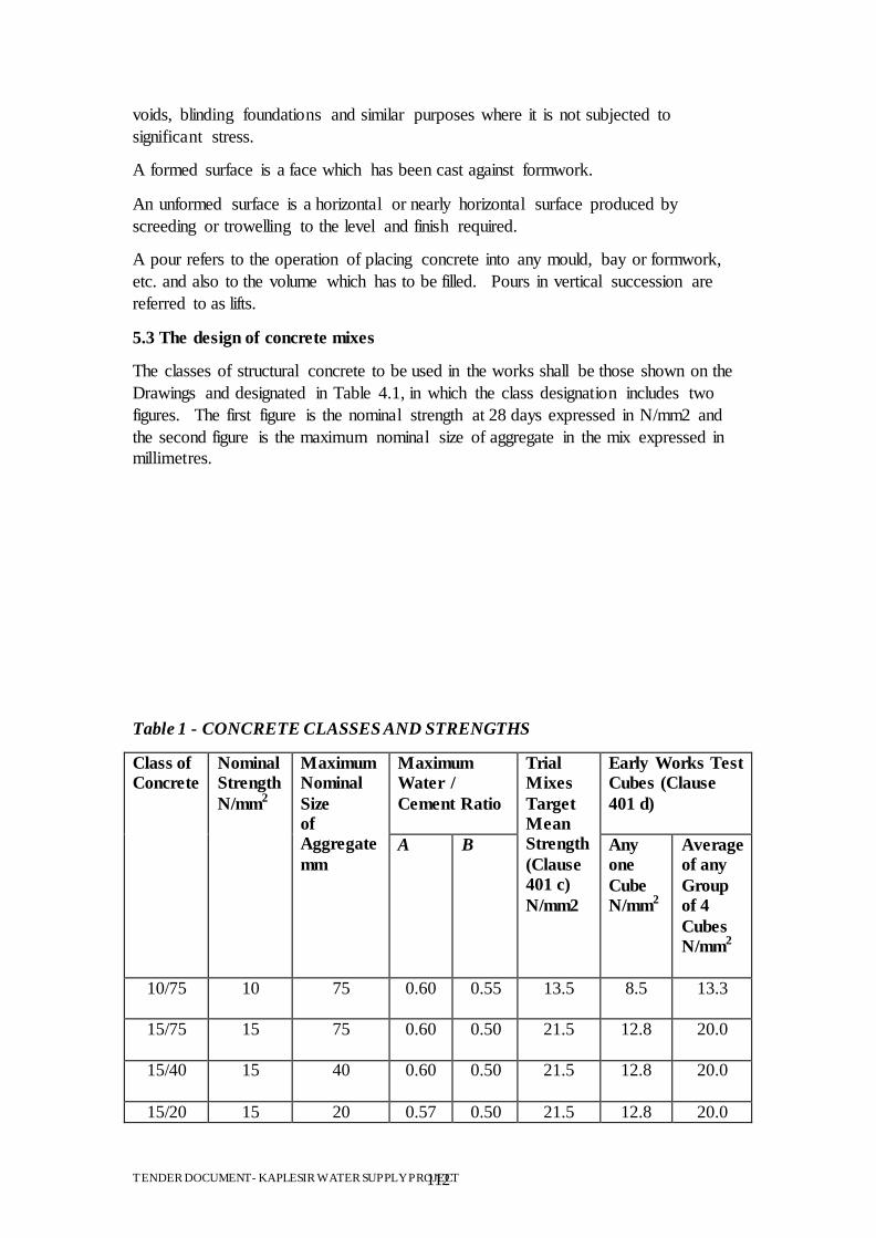
TENDER DOCUMENT- KAPLESIR WATER SUPPLY PROJECT 112
voids, blinding foundations and similar purposes where it is not subjected to
significant stress.
A formed surface is a face which has been cast against formwork.
An unformed surface is a horizontal or nearly horizontal surface produced by
screeding or trowelling to the level and finish required.
A pour refers to the operation of placing concrete into any mould, bay or formwork,
etc. and also to the volume which has to be filled. Pours in vertical succession are
referred to as lifts.
5.3 The design of concrete mixes
The classes of structural concrete to be used in the works shall be those shown on the
Drawings and designated in Table 4.1, in which the class designation includes two
figures. The first figure is the nominal strength at 28 days expressed in N/mm2 and
the second figure is the maximum nominal size of aggregate in the mix expressed in
millimetres.
Table 1 - CONCRETE CLASSES AND STRENGTHS
Class of
Concrete
Nominal
Strength
N/mm2
Maximum
Nominal
Size
of
Aggregate
mm
Maximum
Water /
Cement Ratio
Trial
Mixes
Target
Mean
Strength
(Clause
401 c)
N/mm2
Early Works Test
Cubes (Clause
401 d)
A B Any
one
Cube
N/mm2
Average
of any
Group
of 4
Cubes
N/mm2
10/75 10 75 0.60 0.55 13.5 8.5 13.3
15/75 15 75 0.60 0.50 21.5 12.8 20.0
15/40 15 40 0.60 0.50 21.5 12.8 20.0
15/20 15 20 0.57 0.50 21.5 12.8 20.0
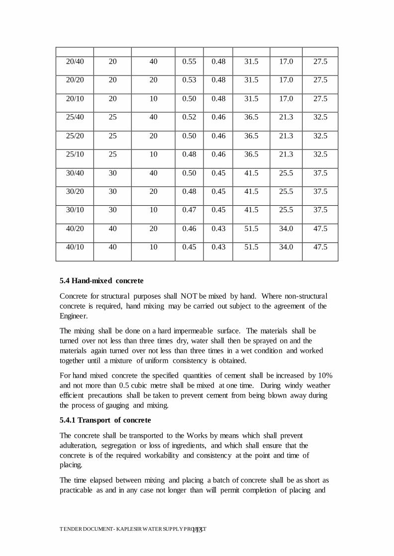
TENDER DOCUMENT- KAPLESIR WATER SUPPLY PROJECT 113
20/40 20 40 0.55 0.48 31.5 17.0 27.5
20/20 20 20 0.53 0.48 31.5 17.0 27.5
20/10 20 10 0.50 0.48 31.5 17.0 27.5
25/40 25 40 0.52 0.46 36.5 21.3 32.5
25/20 25 20 0.50 0.46 36.5 21.3 32.5
25/10 25 10 0.48 0.46 36.5 21.3 32.5
30/40 30 40 0.50 0.45 41.5 25.5 37.5
30/20 30 20 0.48 0.45 41.5 25.5 37.5
30/10 30 10 0.47 0.45 41.5 25.5 37.5
40/20 40 20 0.46 0.43 51.5 34.0 47.5
40/10 40 10 0.45 0.43 51.5 34.0 47.5
5.4 Hand-mixed concrete
Concrete for structural purposes shall NOT be mixed by hand. Where non-structural
concrete is required, hand mixing may be carried out subject to the agreement of the
Engineer.
The mixing shall be done on a hard impermeable surface. The materials shall be
turned over not less than three times dry, water shall then be sprayed on and the
materials again turned over not less than three times in a wet condition and worked
together until a mixture of uniform consistency is obtained.
For hand mixed concrete the specified quantities of cement shall be increased by 10%
and not more than 0.5 cubic metre shall be mixed at one time. During windy weather
efficient precautions shall be taken to prevent cement from being blown away during
the process of gauging and mixing.
5.4.1 Transport of concrete
The concrete shall be transported to the Works by means which shall prevent
adulteration, segregation or loss of ingredients, and which shall ensure that the
concrete is of the required workability and consistency at the point and time of
placing.
The time elapsed between mixing and placing a batch of concrete shall be as short as
practicable as and in any case not longer than will permit completion of placing and
TENDER DOCUMENT- KAPLESIR WATER SUPPLY PROJECT 114
compaction before the onset of initial set. If the placing of any batch of concrete is
delayed beyond this period, the concrete shall not be placed in the Works.
5.4.2 Placing of concrete
a) Consent for placing
Concrete shall not be placed in any part of the Works until the Engineer‟s consent has
been given in writing, and the Contractor shall give the Engineer at least 1 full
working days‟ notice of his intention to place concrete. If concrete placing is not
commenced within 24 hours of the Engineer‟s consent the Contractor shall again
request consent as specified above.
b) Preparation of surface to receive concrete
Excavated surfaces on which concrete is to be deposited shall be prepared as set out in
Section 3 of this Specification.
Existing concrete surfaces shall be prepared as set out in Clause 414. Before
deposition of further concrete they shall be clean, hard and sound and shall be wet but
without any free-standing water.
Any flow of water into an excavation shall be diverted through proper side drains to a
sump, or be removed by other suitable methods which will prevent washing away the
freshly deposited concrete or any of its constituents. Any underdrains constructed for
this purpose shall be completely grouted up when they are no longer required by a
method agreed by the Engineer.
Unless otherwise instructed by the Engineer surfaces against which concrete is to be
placed shall receive a prior coating of mortar mixed in the proportions similar to those
of the fines portion in the concrete to be placed. The mortar shall be kept ahead of the
concrete. The mortar shall be well worked into all parts of the excavated surface and
shall not be less than 5mm thick.
If any fissures have been cleaned out as described in Section 3 of this Specification
they shall be filled with mortar or with concrete as instructed by the Engineer.
The amount of mortar placed at any one time shall be limited so that it does not dry
out or set before being covered with concrete.
c) Chutes
In general, transportation of concrete by the use of chutes will not be permitted unless
approved by the Engineer. The chute shall have a section with round corners and
shall have a proper fixed slope so as to allow the concrete to flow satisfactorily and
without segregation. The lower end of chute shall be provided with a drop chute not
less than 0.6m in height to avoid segregation of falling concrete. The height of drop
shall not exceed 1.5m. Chutes shall be protected from direct sunlight, wind and rain.
d) Placing procedures
The concrete shall be deposited as nearly as possible in its final position. It shall be
placed so as to avoid segregation of the concrete and displacement of the
TENDER DOCUMENT- KAPLESIR WATER SUPPLY PROJECT 115
reinforcement, other embedded items, or formwork. It shall be brought up in layers
approximately parallel to the construction joint planes and not exceeding 500mm in
compacted thickness unless otherwise permitted or directed by the Engineer, but the
layers shall not be thinner than four times the maximum nominal size of aggregate.
Layers shall be placed so that they do not form feather edges nor shall they be placed
on a previous layer which has taken its initial set. In order to comply with this
requirement, a layer may be started before completion of the preceeding layer.
All the concrete in a single bay or pour shall be placed in a continuous operation. It
shall be carefully worked round all obstructions, irregularities in the foundations and
the like so that all parts are completely full of compacted concrete with no segregation
or honeycombing. It shall also be carefully worked round and between water stops,
reinforcement, embedded steelwork and similar items which protrude above the
surface of the completed pour.
All work shall be completed on each batch of concrete before its initial set
commences and thereafter the concrete shall not be disturbed before it has set hard.
No concrete that has partially hardened during transit shall be used in the Works and
the transport of concrete from the mixer to the point of placing shall be such that this
requirement can be complied with.
Concrete shall not be placed during rain which is sufficiently heavy or prolonged as to
wash mortar from coarse aggregate on the exposed faces of fresh concrete. Means
shall be provided to remove any water accumulating on the surface of the placed
concrete. Concrete shall not be deposited into such accumulation of water.
In drying weather, covers shall be provided for all fresh concrete surfaces which are
not being worked on. Water shall not be added to concrete for any reason.
When concrete is discharged above its place of final deposition, segregation shall be
prevented by the use of chutes, downpipes, trunking, baffles or other appropriate
devices, as approved by the Engineer.
e) Interruptions to placing
If concrete placing is interrupted for any reason and the duration of the interruption
cannot be forecast or is likely to be prolonged, the Contractor shall immediately take
the necessary action to form a construction joint so as to eliminate as far as possible
feather edges and sloping top surfaces and shall thoroughly compact the concrete
already placed in accordance with Clause 406. All work on the concrete shall be
completed while it is still plastic and it shall not thereafter be disturbed until it is hard
enough to resist damage. Plant and materials to comply with this requirement shall be
readily available at all times during concrete placing.
Before concreting is resumed after such an interruption the Contractor shall cut out
and remove all damaged or uncompacted concrete, feather edges or any other
undesirable features and shall leave a clean sound surface against which the fresh
concrete may be placed.
TENDER DOCUMENT- KAPLESIR WATER SUPPLY PROJECT 116
If it becomes possible to resume concrete placing without contravening the
Specification and the Engineer consents to a resumption, the new concrete shall be
thoroughly worked in and compacted against the existing concrete so as to eliminate
any cold joints.
f) Dimensions of pours
Unless otherwise agreed by the Engineer, pours shall not be more than two metres
high and shall as far as possible have a uniform thickness over the plan area of the
pour. Concrete shall be placed to the full planned height of all pours except in the
circumstances described in sub-clause 405(d).
The Contractor shall plan the dimensions and sequence of pours in such a way that
cracking of the concrete does not take place due to thermal or shrinkage stresses.
g) Placing sequence
The Contractor shall arrange that as far as possible the intervals between placing
successive lifts of concrete in one section of the Works are of equal duration. This
duration shall normally be not less than three or more than seven days under
temperate weather conditions unless otherwise agreed by the Engineer.
Where required by the Engineer to limit the opening of construction joints due to
shrinkage, concrete shall not be placed against adjacent concrete which is less than 21
days old.
When the drawings call for contraction gaps in concrete, these shall be of the widths
and in the locations shown on the drawings and they shall not be filled until the full
time interval shown on the drawings has elapsed.
5.4.3 Compaction of concrete
The concrete shall be fully compacted throughout the full extent of the placed layer.
It shall be thoroughly worked against the formwork and around any reinforcement and
other embedded items, without displacing them. Particular care shall be taken at
arises and other confined spaces. Successive layers of the same pour shall be
thoroughly worked together.
Concrete shall be compacted with the assistance of mechanical immersion vibrators,
unless the Engineer agrees to another method.
Immersion vibrators shall operate at a frequency of between 7,000 and 10,000 cycles
per minute. The Contractor shall ensure that vibrators are operated at pressures and
voltages not less than those recommended by the manufacturer in order that the
compactive effort is not reduced.
A sufficient number of vibrators shall be operated to enable the entire quantity of
concrete being placed to be vibrated for the necessary period and, in addition, standby
vibrators shall be available for instant use at each place where concrete is being
placed.
TENDER DOCUMENT- KAPLESIR WATER SUPPLY PROJECT 117
Where the concrete contains aggregate with a nominal size of 75mm or more,
vibrators with a diameter of 100mm or more shall be used.
Vibration shall be continued at each point until the concrete ceases to contract, a thin
layer of mortar has appeared on the surface and air bubbles have ceased to appear.
Vibrators shall not be used to move concrete laterally and shall be withdrawn slowly
to prevent the formation of voids.
Vibration shall not be applied by way of reinforcement nor shall vibrators be allowed
to touch reinforcement or other embedded items. The vibrators shall be inserted
vertically into the concrete to penetrate the layer underneath at regular spacing. The
spacing shall not exceed the distance from the vibrator over which vibration is visibly
effective.
5.4.4 Curing of concrete
a) General
Concrete shall be protected during the first stage of hardening from loss of moisture
and from the development of temperature differentials within the concrete sufficient
to cause cracking. The methods used for curing shall not cause damage of any kind to
the concrete.
Curing shall be continued for as long as may be necessary to achieve the above
objectives but in any case for at least seven days or until the concrete is covered by
later construction whichever is the shorter period.
The above objectives are dealt with in sub-clause 407(b) and (c) but nothing shall
prevent both objectives being achieved by a single method where circumstances
permit.
The curing process shall commence as soon as the concrete is hard enough to resist
damage from the process, and in the case of large areas or continuous pours, shall
commence on the completed section of the pour before the rest of the pour is finished.
Details of the Contractor‟s proposals for curing concrete shall be submitted to the
Engineer before the placing of concrete commences in the Works.
Formed surfaces may be cured by retaining the formwork in place for the required
curing period.
If the use of the foregoing methods is inappropriate, surfaces which will not have
further concrete bonded to them and which are not to receive an application of a finish
may be cured by the application of a curing compound having an efficiency index of
at least 90 percent. Curing compounds shall contain a fugitive dye to enable the
extent of the spread to be seen easily.
Curing compound is used on surfaces exposed to the atmosphere shall contain
sufficient finely divided flake aluminium in suspension to produce a complete
coverage of the surface with a metallic finish when applied at the rate recommended
by the manufacturer.
TENDER DOCUMENT- KAPLESIR WATER SUPPLY PROJECT 118
Curing compounds shall become stable and impervious to the evaporation of water
from the concrete surface within 60 minutes of application. The material shall not
react chemically with the concrete surfaces for at least the first four days of the curing
period.
If instructed by the Engineer, the Contractor shall, in addition to the curing provisions
set out above provide a suitable form of shading to prevent the direct rays of the sun
reaching the concrete surfaces for at least the first four days of the curing period.
b) Loss of moisture
Exposed concrete surfaces shall be closely covered with impermeable sheeting,
properly secured to prevent its removal by wind and the development of air spaces
beneath it. Joints in the sheeting shall be lapped by at least 300mm.
If for some reason it is not possible to use impermeable sheeting, the Contractor shall
keep the exposed surfaces continuously wet by means of a water spray or by covering
with a water absorbent material which is kept wet, unless this method conflicts with
sub-clause 407(c).
Water used for curing shall be of the same quality as that used for concrete mixing as
stated in sub clause 702(g).
c) Limitation of temperature differential
The Contractor shall limit the development of temperature differentials in concrete
after placing by any means appropriate to the circumstances including the following:
i) limiting concrete temperatures at placing as set out in sub-clause 409(b); ii) use of
low heat cement, subject to the agreement of the Engineer; iii) insulation of exposed
concrete surface by insulating blankets. Such blankets shall have an insulation value
at least equivalent to 50mm of dry mineral wool;
iv) leaving formwork in place during the curing period. Steel forms shall be suitably
insulated on the outside; v) preventing rapid dissipation of heat from surfaces by
shielding from wind; vi) avoiding the use of water sprays when such use would cause
rapid cooling of the surface.
5.4.5 Protection of fresh concrete
Freshly placed concrete shall be protected from rainfall and from water running over
the surface until it is sufficiently hard to resist damage from these causes.
No traffic shall be allowed on any concrete surface until such time as it is hard enough
to resist damage by such traffic.
Concrete placed in the Works shall not be subjected to any loading until it has
attained at least its nominal strength as defined in Clause 401.
If the Contractor desires to impose loads on newly-placed concrete, he shall make at
least three test cubes and cure them in the same conditions as the concrete they
represent. These cubes shall be tested singly at suitable intervals in order to estimate
the time at which the nominal strength is reached.
TENDER DOCUMENT- KAPLESIR WATER SUPPLY PROJECT 119
5.4.6 Concreting in hot weather
a) General
The Contractor shall prevent damage to concrete arising from exposure to extreme
temperatures, and shall maintain in good working order all plant and equipment
required for this purpose.
In the event that conditions become such that even with the use of the equipment the
requirements cannot be met, concrete placing shall immediately cease until such time
as the requirements can again be met.
b) Concrete placing in hot weather
During hot weather the Contractor shall take all measures necessary to ensure that the
temperature of concrete at the time of placing in the Works does not exceed 30
degrees centigrade and that the concrete does not loose any moisture during
transporting and placing.
Such measures may include but are not necessarily limited to the following:
i) Shielding aggregates from direct sunshine. ii) Use of a mist water spray on
aggregates iii) Sun shields on mixing plants and transporting equipment. iv) Cooling
the mixing water. If ice is used for this purpose it should preferably be in flake form.
Lump ice shall not be allowed to enter the tank supplying the mixer drum. v)
Covering skips closely with polythene sheet so that the latter is in contact with the
concrete.
Areas in which concrete is to be placed shall be shielded from direct sunshine and
rock or concrete surfaces shall be thoroughly wetted to reduce absorption of water
from the concrete placed on or against them.
After concrete in any part of an area has been placed, the selected curing process shall
be commenced as soon as possible. If any interval occurs between completion of
placing and start of curing, the concrete shall be closely covered during the interval
with polythene sheet to prevent loss of moisture.
5.4.7 Finishes on unformed surfaces
Horizontal or nearly horizontal surfaces which are not cast against formwork shall be
finished to the class shown on the drawings and defined hereunder.
UF 1 Finish
All surfaces on which no higher class of finish is called for on the drawings or
instructed by the Engineer shall be given a UF 1 finish.
The concrete shall be levelled and screeded to produce a uniform plain or ridged
surface, surplus concrete being struck off by a straight edge immediately after
compaction.
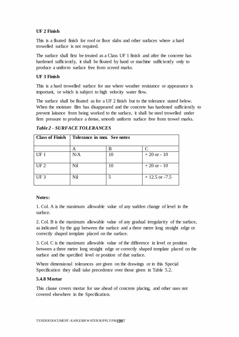
TENDER DOCUMENT- KAPLESIR WATER SUPPLY PROJECT 120
UF 2 Finish
This is a floated finish for roof or floor slabs and other surfaces where a hard
trowelled surface is not required.
The surface shall first be treated as a Class UF 1 finish and after the concrete has
hardened sufficiently, it shall be floated by hand or machine sufficiently only to
produce a uniform surface free from screed marks.
UF 3 Finish
This is a hard trowelled surface for use where weather resistance or appearance is
important, or which is subject to high velocity water flow.
The surface shall be floated as for a UF 2 finish but to the tolerance stated below.
When the moisture film has disappeared and the concrete has hardened sufficiently to
prevent laitance from being worked to the surface, it shall be steel trowelled under
firm pressure to produce a dense, smooth uniform surface free from trowel marks.
Table 2 - SURFACE TOLERANCES
Class of Finish Tolerance in mm. See notes
A B C
UF 1
N/A 10 + 20 or - 10
UF 2
Nil 10 + 20 or - 10
UF 3
Nil 5 + 12.5 or -7.5
Notes:
1. Col. A is the maximum allowable value of any sudden change of level in the
surface.
2. Col. B is the maximum allowable value of any gradual irregularity of the surface,
as indicated by the gap between the surface and a three metre long straight edge or
correctly shaped template placed on the surface.
3. Col. C is the maximum allowable value of the difference in level or position
between a three metre long straight edge or correctly shaped template placed on the
surface and the specified level or position of that surface.
Where dimensional tolerances are given on the drawings or in this Special
Specification they shall take precedence over those given in Table 5.2.
5.4.8 Mortar
This clause covers mortar for use ahead of concrete placing, and other uses not
covered elsewhere in the Specification.
TENDER DOCUMENT- KAPLESIR WATER SUPPLY PROJECT 121
Mortar shall be composed of fine aggregate complying with sub-clause 702(c) and
ordinary Portland cement complying with SRN 103. The mix proportions shall be as
stated on the drawings or elsewhere in this Specification or if not stated shall be one
part of cement to two parts of fine aggregate by weight.
Small quantities of mortar may be hand mixed but for amounts over 0.5 cubic metre a
mechanical mixer shall be used.
The water content of the mortar shall be as low as possible consistent with the use for
which it is required but in any case the water/cement ratio shall not be more than 0.5.
Mortar which is specified as „dry pack‟ shall be mixed with sufficient water for the
mix to become cohesive but not plastic when squeezed in the hand. Dry pack mortar
shall be rammed into the cavity it is required to fill, using a hand rammer with
sufficient force to ensure full compaction.
5.4.9 Remedial work to defective surfaces
If on stripping any formwork the concrete surface is found to be defective in any way,
the Contractor shall make no attempt to remedy such defects prior to the Engineer‟s
inspection and the receipt of any instructions which the Engineer may give.
Defective surfaces shall not be made good by plastering.
Areas of honey combing (of a mild nature) which the Engineer agrees may be
repaired shall be cut back to sound concrete or to 75mm whichever is the greater
distance. In the case of reinforced concrete the area shall be cut back to at least 25mm
clear distance behind the reinforcement or to 75mm, whichever is the greater distance.
The cavity shall have sides at right angles to the face of the concrete. After cleaning
out with water and compressed air, a thin layer of cement grout shall be brushed on to
the concrete surface in the cavity and it shall then be filled immediately with concrete
of the same class as the main body but with aggregate larger than 20mm nominal size
removed. A form shall be used against the cavity, provided with a lip to enable
concrete to be placed. The form shall be filled to a point above the top edge of the
cavity.
After seven days the lip of concrete shall be broken off and the surface ground
smooth.
Surface irregularities which are outside the limits of tolerance set out in Clause 410
shall be ground down in the manner and to the extent instructed by the Engineer.
Severe honeycombing and defects other than those mentioned above shall be dealt
with as instructed by the Engineer.
5.5 Material
5.5.1 Material for concrete
a) General
The Contractor shall submit to the Engineer full details of all materials which he
proposes to use for making concrete. No concrete shall be placed in the Works until
TENDER DOCUMENT- KAPLESIR WATER SUPPLY PROJECT 122
the Engineer has approved the materials of which it is composed. Approved materials
shall not thereafter be altered or substituted by other materials without the consent of
the Engineer.
b) Cement
Cement shall comply with the following Kenya Standards:
SRN 103 for Ordinary Portland cement.
SRN 103 for Rapid Hardening Portland cement plus all special conditions to its use
stipulated by the manufacturer.
SRN 104 for Sulphate Resisting or High Alumina cement.
Cement shall be free flowing and free of lumps. It shall be supplied in the
manufacturer‟s sealed unbroken bags or in bulk. Bagged cement shall be transported
in vehicles with effective means of ensuring that it is protected from the weather.
Bulk cement shall be transported in vehicles or in containers specially built and
equipped for the purpose.
Cement in bags shall be stored in a suitable weatherproof structure of which the
interior shall be dry and well ventilated at all times. The floor shall be raised above
the surrounding ground level and shall be so constructed that no moisture rises
through it.
Each delivery of cement in bags shall be stacked together in one place. The bags shall
be closely stacked so as to reduce air circulation but shall not be stacked against an
outside wall. If pallets are used, they shall be constructed so that bags are not
damaged during handling and stacking. No stack of cement bags shall exceed 3
metres in height. Different types of cement in bags shall be clearly distinguished by
visible markings and shall be stored in separate stacks.
Cement from broken bags shall not be used in the Works.
Cement in bags shall be used in the order in which it is delivered.
Bulk cement shall be stored in weatherproof silos which shall bear a clear indication
of the type of cement contained in them. Different types of cement shall not be mixed
in the same silo.
The Contractor shall provide sufficient storage capacity on site to ensure that his
anticipated program or work is not interrupted due to lack of cement.
Cement which has become hardened or lumpy or fails to comply with the
Specification in any way shall be removed from the site.
All cement for any one structure shall be from the same source.
Cement which is stored on site for longer than one month shall be rejected.
c) Fine Aggregate
TENDER DOCUMENT- KAPLESIR WATER SUPPLY PROJECT 123
Fine aggregate shall be clean, hard and durable and shall be natural sand, crushed
gravel sand or crushed rock sand complying with SRN 108. All the material shall
pass through a 5mm standard sieve and the grading shall be in accordance with Zones
1, 2 or 3 of SRN 109. In order to achieve an acceptable grading, it may be necessary
to blend materials from more than one source. Fine aggregate for mortar only shall
comply with SRN 135.
The fine aggregate shall not contain iron pyrites or iron oxides. It shall not contain
mica, shale, coal or other laminar, soft or porous materials or organic matter unless
the Contractor can show by comparative tests, on finished concrete as set out in SRN
117, that the presence of such materials does not adversely affect the properties of the
concrete.
d) Coarse aggregate
Coarse aggregate shall be clean, hard and durable crushed rock, crushed gravel or
natural gravel complying with the requirements of SRN 110. The material shall not
contain any iron pyrites, iron oxides, flaky or laminated material, hollow shells, coal
or other soft or porous material, or organic matter unless the Contractor can show by
comparative tests on finished concrete as set out in SRN 117 that the presence of such
materials does not adversely affect the properties of the concrete. The pieces shall be
angular, rounded or irregular as defined in SRN 107.
Coarse aggregate shall be supplied in the nominal sizes called for in the Contract and
shall be graded in accordance with SRN 111 for each nominal size.
f) Delivery and storage of aggregates
Aggregates shall be delivered to site in clean and suitable vehicles. Different types or
sizes of aggregate shall not be delivered in one vehicle.
Each type or size of aggregate shall be stored in a separate bin or compartment having
a base such that contamination of the aggregate is prevented. Dividing walls between
bins shall be substantial and continuous so that no mixing of types or sizes occurs.
The storage of aggregates shall be arranged so that as far as possible rapid drying out
in hot weather is prevented in order to avoid sudden fluctuations in water content.
Storage of fine aggregates shall be arranged so that they can drain sufficiently before
use in order to prevent fluctuations in water content of the concrete.
g) Water for concrete and mortar
Sea water or brackish water containing more than 1,000 ppm chloride ion or 2,000
ppm sulphate ion shall not be used for mixing or curing concrete.
Water shall be clean and free from harmful matter and shall comply with the
requirements of SRN 114.
The Contractor shall carry out tests in accordance with SRN 114 to establish
compliance with the Specification.
5.5.2 Building stone
TENDER DOCUMENT- KAPLESIR WATER SUPPLY PROJECT 124
All building stone shall be capable of withstanding when wet a crushing stress of 1.4
kg./sq.mm. The source of stone shall be approved by the Engineer and stone supplied
there from shall be free from Magadi, overburden, mudstone, cracks, sandholes,
veins, laminations or other imperfections.
The stone shall be chisel dressed into true rectangular blocks, with each surface even
and at right angles to all adjoining surfaces, to the size specified. For exposed
stonework the maximum permissible variation of any of the specified dimensions
shall be 6mm provided that cut stone, supplied as „rock face‟ stone may be hammer
dressed on one face only, or on one face and one end, if in other respects it conforms
with this specification. Stones shorter than 375mm will not be accepted.
Unless the Engineer allows otherwise the Contractor shall at his own expense provide
and dress four 100mm cubes of stone for testing.
The stone shall be sound when tested in accordance with SRN 870 except that:
i) The treatment shall be repeated for 10 cycles only; and
ii) The second criterion of failure shall be amended to allow for a loss of weight
of not more than 20% of its original weight.
5.5.3 Murram
Murram shall be from an approved source quarried so as to exclude vegetable matter,
loam, top soil or clay. The California Bearing Ratio of the murram, as determined for
a sample compacted to maximum density (as defined under SRN 601) and allowed to
soak in water for four days, shall not be less than 30%. This C.B.R. is a guide to
quality only and the compaction in the work will be judged by density.
5.5.4 Cement mortar
Cement mortar shall consist of proportions by volume as specified of Portland cement
and natural sand or crushed natural stone or a combination of both as specified in
SRN 135 and SRN 136: Building Sands from Natural Sources. The constituent
materials shall be accurately gauged and mixed in an approved manner.
Cement mortar shall be made in small quantities only as and when required, and any
mortar which has begun to set or which has been mixed for a period of more than one
hour shall be rejected.
5.5.5 Concrete blocks
Solid and hollow concrete blocks for walling shall comply with SRN 904 in every
respect.
All solid and hollow concrete blocks used in the walling must be capable of
withstanding a crushing pressure of not less than 0.35 kg per square millimeter after
28 days. The blocks shall be cast in Metric sizes.
5.5.6 Cement
The cement to be used in the works shall be obtained from approved Manufacturer
and the cement shall comply with one of the following sub-Clauses (I) to (iv) below:
TENDER DOCUMENT- KAPLESIR WATER SUPPLY PROJECT 125
BS 12 (Ordinary and rapid-hardening Portland cement).
BS 146 (Portland-blast furnace cement).
BS 4027 (Sulphate resisting Portland cement).
BS 6588 (Portland pulverized-fuel ash cement) provided that sub-Clause (vii) below
is complied with.
A mixture of BS 12 (Portland cement) and BS 3892: Part 1 (Pulverized-fuel ash for
use in structural concrete) provided that the amount of pulverized-fuel ash is not less
than 15% nor more than 35% by weight of the total cement and sub-Clause
(vii)below is complied with.
A mixture of BS 12 (Portland cement) and BS 6699 (Ground granulated blast
furnace slag for use with Portland cement) provided that the amount of slag is not
more than 65% by weight of the total cement.
The pulverized-fuel ash used shall have a maximum color index of 6 (Color
comparator disc reference No. 296570) when measured using the Lovi bond Color
Comparator system as recommended in BS 3892: Part 1 Appendix H, Clause H8.
Cement shall be fresh when delivered to Site and the consignments shall be used in
the order of their delivery. The Contractor shall mark the date of delivery on each
consignment and each consignment shall be stored separately and in such manner as
to be easily accessible and identifiable. No cement in bags or other containers
shall be used unless these and the manufacturer's seals are intact at the time of
mixing.
If the cement is delivered in bags it shall be stored in a waterproof shed or
building at a temperature of not less than 8oC and the bags shall be placed on dry
boards above the floor to prevent deterioration or contamination from any cause. Bulk
cement may be used provided it is stored in an approved container.
The Contractor shall not use cement, which has hardened into lumps, but subject to
removal of the lumps by screening, the Engineer may allow such cement to be used in
non-structural concrete mixes. Any cement which is stored on site for a period in
excess of 28 days shall be tested in accordance with the relevant standard prior to use.
Cement of different types shall be kept separate in storage and shall not be mixed
together in the production of concrete. If intermixing occurs all cement concerned will
be condemned by the Engineer and shall be removed immediately from site.
No cement containing hardening or waterproofing compounds shall be used nor shall
calcium chloride or other chemicals be added to cement or to concrete except on the
instructions of the Engineer. Any cement so treated shall be stored separately and
clearly marked and shall only be used in accordance with the requirements of the
Engineer.
It shall be stored off the ground and under cover, thoroughly dry and well ventilated.
Cement in bags shall not be stacked more than 2m high. Each batch shall be stacked
separately and be easily identifiable and used in the order of delivery. No cement shall
TENDER DOCUMENT- KAPLESIR WATER SUPPLY PROJECT 126
be used which has been manufactured more than twelve (12) months prior to its
proposed use on Site.
5.5.7 Water
Water used in the Works shall be clean, fresh, water free from all deleterious matter,
silt, organic matter, alkali, slate and other impurities. It shall preferably be from a
potable water source (from the public water supply network) or from other approved
sources.
Where water can be obtained from a public water supply it shall be used. Where water
cannot be obtained from a public supply it shall be tested in accordance with BS 3148
and if necessary shall be treated to assure compliance therewith.
Water for washing and curing shall be such that it will impair neither the
strength of the finished concrete nor its appearance.
5.5.8 Aggregates
Aggregates shall be obtained from a source to be approved by the Engineer. Coarse
and fine aggregates shall be delivered and stored separately on to a clean, hard
base, in separate compartments or into approved hoppers. Samples of aggregates
and sand for use on the works shall be submitted and the together with tests results
from reputable materials testing laboratories.
Fine and coarse aggregates shall be as defined by and be of the quality and nature
required by BS 882 and BS 1201 whichever is applicable. In addition they shall be
chemically inert to alkali reaction.
Aggregates shall conform to the requirements of the Standards. Aggregates of
rounded shape or otherwise capable of producing concrete of good workability with
the minimum addition of water shall be preferred.
The Contractor shall ensure that the nature and grading of aggregates remain
reasonably consistent, and shall, if necessary, stockpile and include different grading
to ensure that the overall grading remains constant for each section of the work.
Dust or flour resulting from crushing the aggregate shall not be allowed to
contaminate the stockpiles. When, in the opinion of the Engineer, such contamination
has taken place it shall be removed by an approved means or otherwise the aggregate
shall be rejected.
For mass concrete, in order to improve the consistency of the mix, dust or
flour resulting from crushing the aggregate, may, subject to test, be included in
controlled quantities to supplement the fine aggregate.
The aggregates of various sizes shall be kept separate and away from all
possible contamination, and shall be stored on a hard-standing area or in bins
and provided with proper drainage at the base of the stockpiles.
Except where aggregates have been otherwise specified on the Drawings the
grading of aggregates shall be as follows:
TENDER DOCUMENT- KAPLESIR WATER SUPPLY PROJECT 127
Coarse Aggregate:
10 mm max. Size, graded, for all "fine" concrete.
20 mm max. Size, graded, for all reinforced concrete in beams and for wall sand slabs
not greater than 400 mm thick.
40 mm max. Size, graded, for all reinforced concrete walls and slabs in excess of 400
mm thick.
Fine Aggregate:
Where aggregates conforming to Zones 2 or 3 of BS 882 are available they shall be
used.
For Prescribed Mixes, Zones 1, 2, or 3 aggregates only shall be used.
Additives
The concrete shall be made from the cement, aggregates and water as specified. No
other ingredients shall be mixed with the concrete without the prior written approval
of the Project Manager‟s Rep .
5.5.9 Reinforcement
Steel
Reinforcement shall be:
Plain round mild steel or High Yield steel bars conforming to BS 4449.
Cold worked steel bars conforming to BS 4461
Fabric reinforcement made of cold drawn high tensile bars conforming to BS4483.
The Contractor shall obtain from his suppliers‟ certificates of the mechanical
and physical properties of the reinforcement and shall submit them to the Engineer
for approval, except where reinforcement has been supplied by the Employer. The
frequency of sampling and the method of quality control shall be in accordance with
Table 4 and Clause 20 respectively of these British Standards. All high yield and
cold worked bars (except in welded fabric reinforcement) shall be deformed
bars complying with Classification Type T2 for bond strength in accordance
with BS 4449. Where galvanized reinforcement is specified, galvanizing shall
comply with the requirements of BS 729, Part 1.
Steel tying wire for reinforcement shall comply with the relevant Kenyan Standards
and be 3-4 mm in diameter.
Bending and Fixing
The Contractor shall provide on Site facilities for cutting and bending reinforcement
whether he is ordering his reinforcement bent or not and shall ensure that a token
amount of straight bar is available on Site for bending as and when directed by the
Engineer.
TENDER DOCUMENT- KAPLESIR WATER SUPPLY PROJECT 128
Reinforcement shall be wire brushed and cleaned at the Contractor's expense, before
and/or after it is placed in position, if required by the Engineer.
The bars shall be cold bent in strict accordance with the drawings and the Contractor
shall be responsible for the accuracy of the bending. Bending dimensions shall be
worked to the tolerances indicated in BS 4466 and BS 8110 table 3.26. Bars in which
any errors in bending are beyond the limits of the foregoing tolerances shall be
replaced at the Contractor's cost by correctly bent new bars, or, may be
straightened and recent cold subject to the Engineer's prior approval. Any
discrepancy or inaccuracy found in the drawings shall be notified to the Engineer
immediately.
After bending, reinforcement shall be securely bundled and labeled with weather-
proof tags or shall be marked with other approved signs by which it can readily be
identified.
Before assembling or fixing the reinforcement the dimensions to which it has been
bent shall be checked by the Contractor against the drawings. The reinforcement
shall be fixed in strict accordance with the drawings as regards cover, spacing
and position, and suitable precautions shall be taken by the Contractor to prevent the
displacement of reinforcement during the placing and compaction of concrete.
Where required to support and retain the reinforcement in its correct position the
Contractor shall provide templates, stools or other supports at his own cost. He shall
allow for cutting to correct length all corner lacer bars included in the bar schedules as
standard lengths.
Precast concrete support blocks for reinforcement shall be manufactured from Grade
C30D "fine" concrete to ensure the correct cover thickness. They shall be well cured
before use and carefully stored on Site to avoid contamination. Plastic and metal
supports, chairs, etc. may be used and shall be subject to the Engineer's prior
approval.
In the case of mild steel, a lap of not less than 40 diameters of the smaller
bar shall be provided at the junction of two bars for which the lap is not
specifically detailed on the Drawings and, in the case of High Yield steel, a lap of
not less than 50 diameters.
All intersections of bars in walls and slabs and all connections between binders or
links and main bars in columns or beams shall be tied with soft iron wire ties or with
fixing clips which shall not be allowed to make contact with the formwork or to
project materially into the specified cover.
Unless permitted by the Engineer, welding of bar reinforcement at intersections
or for the joining of bars is prohibited. Where permission is granted, welding shall
be carried out in accordance with the recommendations of the Institute of
Welding for the welding of reinforcing bars for reinforced concrete construction.
When fixed reinforcement is to be left exposed for a delayed period of time,
it shall be thoroughly cleaned and painted with neat cement grout.
TENDER DOCUMENT- KAPLESIR WATER SUPPLY PROJECT 129
Where galvanized reinforcement is used any damage suffered by galvanizing shall be
made good by the application of an approved galvanizing formulation, before
concrete placing is commenced.
Couplers
Couplers for reinforcement shall be either Standard Swaged Splices or Type II
Alpha Couplers manufactured by CCL Systems Limited, or similar approved.
Where bars of different diameters are to be joined a CCL Reducer Sleeve or similar
shall be used.
Couplers shall be suitable for the type and size of reinforcing bars and shall be
capable of developing 115% of the characteristic strength of the smaller of the
reinforcing bars being joined in both tension and compression. Couplers shall be
installed in accordance with the manufacturer‟s recommendations. Square twisted
reinforcing bars shall not be used with couplers.
Supply and Testing
All reinforcement shall be obtained from a manufacturer approved by the Project
Manager‟s Rep. The Contractor shall have samples of the steel tested as specified by
the Project Manager‟s Rep by a testing authority approved by the Project Manager‟s
Rep to prove that the quality is in accordance with the specifications. The costs of
such tests will be borne by the Contractor. The Contractor shall supply to the Project
Manager‟s Rep a manufacturer's test certificate in respect of each batch of
reinforcement delivered to Site together with the delivery note giving details of such
consignment.
Reinforcement steel shall be delivered firmly tied in bundles. On all bundles shall be
indicated on the outside, the manufacturer and the quality, the date of delivery at the
Site and the length, diameters and number of bars.
Reinforcement steel shall be stored in racks, clear off the ground and shall be
protected from rusting, damage and oil or other deleterious matter.
5.5.10 Control of Alkali-Silica Reaction
The risk of cracking and expansion due to alkali-silica reaction shall be
minimized by compliance with the specification and guidance notes set out in
Concrete Society Technical Report No. 30.
5.6 Concrete
The Contractor shall design and form all concrete to meet the requirements of this
Specification and the associated service conditions. These requirements are directed
to the achievement of durability as well as strength. All concrete shall be designed for
a Severe Exposure Condition as indicated in BS 8110, Clause
4.3.2. Water retaining structures shall be designed to BS 8007. All other concrete
shall be designed to BS8110.
TENDER DOCUMENT- KAPLESIR WATER SUPPLY PROJECT 130
The concrete shall be designed to resist chemical attack by the water and soil into
which it will come into contact. Evidence of this design, using internationally
recognized codes, shall be submitted to the Project Manager‟s Rep.
5.6.1 Ready-mixed Concrete
Where concrete is to be obtained from a ready-mix supplier, the Contractor shall
obtain the Project Manager‟s Rep 's approval of the source and shall satisfy the
Project Manager‟s Rep that the supplying plant is capable of producing concrete to
the required standard. The Contractor shall also inform the Project Manager‟s Rep
what alternative suppliers are available to him if the approval of the source referred to
above has to be withdrawn by the Project Manager‟s Rep during the currency of the
Contract.
The delivery ticket required for each load of ready mixed concrete shall detail:
the grade or mix description of the concrete
the specified workability
the minimum cement content
the maximum free water/cement ratio
the quantity of concrete in cubic meters
the time of loading
the type and nominal maximum size of aggregate
the type or name and proportion of any admixture,
the actual cementitious content and the percentage of any Pfa or Ggbs
included
the position of the concrete in the Works.
All delivery tickets shall be kept at the Site and shall be made available for inspection
by the Project Manager‟s Rep.
The full requirements for the materials and workmanship specified herein, including
all sampling, testing and returns, shall apply equally to concrete mixed on site as to
ready-mixed concrete.
Water shall not be added to concrete in a truck mixer drum other than at the batching
plant. The mix shall be continuously agitated during transportation. The transportation
and placing times shall be reviewed and rigidly enforced in relation to the
circumstances of distance and risk of traffic delays I transit.
5.6.2 Concrete Mixes
Schedules for specifying concrete (Forms A, B, C and D) are appended at the end of
this section. These are to be completed by the Contractor for any Contractor-designed
elements and submitted to the Project Manager‟s Rep for approval prior to the
Contractor placing an order for the supply of concrete. The 4 mix types are defined as
follows.
a) Designed mix: Mix for which the purchaser is responsible for specifying
the required performance and the producer is responsible for selecting the mix
proportions to produce the specified performance.
TENDER DOCUMENT- KAPLESIR WATER SUPPLY PROJECT 131
b) Prescribed mix: Mix for which the purchaser specifies the proportions of
the constituent materials and is responsible for ensuring that these proportions
produce a concrete with the required performance.
c) Standard mix: Mix selected from the restricted list given in section 4
ofBS5328 Part 2 1997 and made with a restricted range of materials.
d) Designated mix: Mix produced in accordance with the specification given in
section 5 of BS5328 Part 2 1997 and requiring the producer to hold current product
conformity certification based on product testing and surveillance coupled with the
approval of the producer's quality system to BS EN ISO9001.
Concrete mixes designed by the Contractor shall take adequate precautions against the
risk of cracking from thermal contraction and shrinkage and alkali-aggregate
reactivity.
At least four weeks before any concrete works are proposed, the Contractor shall
submit to the Project Manager‟s Rep, and obtain his approval before concreting
commences, the following information:
The nature and source of each constituent material. The source of supply of concrete
and any alternative sources that may be used. Details of all concrete mixes such
as:concrete grade the proposed proportions or quantity of each constituent per cubic
meter of fully compacted concrete air content of air-entrainment if applicable
chloride, reactive alkali and sulphate contents target workability
e) Details of the proposed general method of construction, striking times of
formwork, the methods of placing concrete, and the size and sequence of concrete
pours.
f) The proposed methods of curing concrete. The Project Manager‟s Rep shall be
informed of any changes to the source of constituent materials or their proportions.
5.6.3 Trial Mixes
Unless existing data on materials and properties of concrete mixes are available,
preliminary laboratory tests shall be carried out to determine that the mixes satisfy the
specification with the available materials.
Where field trial mixes are required, three separate batches of concrete shall be made
using materials typical of the proposed source of supply and, where practicable, under
full scale production conditions.
The workability, air content and density of each of the trial batches shall be
determined and three cubes made from each batch for test at 28 days. The average 28-
day strength of the three trial mixes shall not be less than the design target mean
strength.
5.6.4 Concrete Mixes Containing PFA or GGBS
TENDER DOCUMENT- KAPLESIR WATER SUPPLY PROJECT 132
The free water /cementitious ratio of concrete mixes containing pfa shall be reduced
in relation to the pfa content, consistent with maintenance of the required workability,
and shall not exceed 0.50 for concrete designed to retain an aqueous liquid.
Sulphate-resisting cement shall not be used in concrete mixes containing pfa.
Sulphate-resisting cement shall not be used in concrete mixes containing ggbs.
8.6.5 Porous No-fines Concrete
Porous no-fines concrete shall contain ordinary Portland cement and 20mm single
sizes aggregate in a proportion of 1:10 by mass.
The concrete shall be mixed to a uniform color and consistency with the addition of
water sufficient only to coat all of the aggregate without forming excess grout.
The concrete shall not be mechanically vibrated or excessively worked when placed.
8.6.6 Air-entrained Concrete
Where air-entrained concrete is required, it shall have an average air content by
volume of the fresh concrete at the time of placing of 5%-7% measured using an air-
entrainment meter.
5.6.7 Chloride Content
Calcium chloride or admixtures containing calcium chloride shall not be used in the
production of reinforced concrete or concrete which is to contain embedded metal.
The total estimated content of chloride ion by mass of cement in reinforced concrete
or concrete which is to contain embedded metal shall not exceed the following limits:
TABLE 3: CHLORIDE ION LIMITS FOR CONCRETE CONTAINING
EMBEDDED METALS
Portland cement concrete ,or combination with Pfa and Ggbs 0.3%
Concrete made with sulphate resisting cement 0.2%
Steam –cured and prestressed concrete 0.1%
5.6.8 Batching and Mixing
Cementitious components and aggregates shall be batched by mass to within ±2% of
the target batch masses. Water and admixtures shall be batched by volume to within
±1% of the target batch volumes.
Due allowance shall be taken of the moisture content of the aggregates when batching
the aggregates and water.
Mixing shall be by a forced impeller action pan mixer or horizontal axis drum mixer.
The batch quantities shall be between 30% and 60% of the rated capacity of the
mixer.
The time of mixing shall not be less than 2 minutes and shall be sufficient to produce
a concrete of uniform color.
5.6.9 Workability
TENDER DOCUMENT- KAPLESIR WATER SUPPLY PROJECT 133
Workability of fresh concrete shall be such that the concrete can be handled and
placed without segregation and, after compaction, can completely fill the formwork
and surround all reinforcement and ducts.
5.6.10 Transporting, Placing and Compacting
Concrete shall be transported from the mixer and placed in the Works as rapidly as
practicable by methods which will prevent the segregation or loss of any of the
ingredients and will maintain the required workability. It shall be deposited as
nearly as practicable in its final position and all equipment for transporting concrete
shall be kept clean. The Contractor shall give to the Project Manager‟s Rep not less
than 24 hours written notification of his intention to pour concrete.
Concrete shall be thoroughly compacted in its final position within 30 minutes of
discharge from the mixer, unless carried in purpose-made agitators operating
continuously, when the time shall be within 2 hours of the introduction of the cement
to the mix and within 30 minutes of the discharge from the agitator.
The plant used for compaction shall be operated continuously during the placing of
each batch of concrete until the expulsion of air has virtually ceased, and in a manner
which does not promote segregation of the ingredients.
Whenever vibration has to be applied externally, the design of formwork and
disposition of vibrators shall be such as to ensure efficient compaction and to avoid
surface blemishes.
Placing shall not be commenced until the fixing and condition of reinforcement and
items to be embedded and the condition of the containing surfaces or formwork have
been approved.
Concrete shall be transported by means which prevent contamination (by dust, rain
etc.), segregation or loss of ingredients, and shall be transported and placed without
delay. The height of concrete to be placed in one pour shall be agreed with the Project
Manager‟s Rep before placing commences. Concrete shall be placed directly in its
final position without displacement of the reinforcement, embedded items and
formwork.
The size and sequence of pours in either precast units or in situ concrete, and the
sequence of erection and in situ connection of precast units, shall be arranged in such
a manner as to minimize internal and external restraint and associated thermal and
shrinkage cracking. Detailed methods shall be set out by the Contractor in his method
statements.
Vibration shall not be applied directly or indirectly to concrete after the initial set has
taken place, nor shall it be used to make concrete flow in formwork.
Placing in each section of work shall be continuous between construction joints. The
Contractor shall make provision for standby equipment. If the placing of concrete is
delayed by more than 30 minutes due to breakdown then the Contractor shall erect
vertical stop ends and form a construction joint or remove the concrete already placed
and restart after repair of the breakdown, as directed.

TENDER DOCUMENT- KAPLESIR WATER SUPPLY PROJECT 134
Placing shall not take place in the open during storms, heavy rains or snow. If such
conditions are likely to occur the Contractor shall provide protection for the materials,
plant and formwork so that work may proceed. If strong winds are prevalent,
protection from driving rain and dust shall be provided. The Contractor shall agree a
casting sequence with the Project Manager‟s Rep at least 7 days before placing
concrete. The Contractor shall cast concrete bays sequentially and shall avoid infill
panels.
5.6.11 Concrete Temperature
The resultant temperature of the combined materials in any batch of concrete at the
point and time of delivery to the Works shall not exceed 60C above the prevailing
shade temperature, when the latter is over210C.
Where the temperature of the fresh concrete is likely to exceed 320C, concreting shall
not be permitted unless measures are taken to keep the temperature below that level.
These measures may include, but not be restricted to the following:
cooling the mixing water
shading the materials
spraying the aggregates with water
painting the plant white
5.6.12 Curing
Concrete shall be cured for a period not less than 7 days when the ambient
temperature is 200C or greater by methods that shall ensure that cracking, distortion
and efflorescence are minimized.
Where the temperature is below 200C the curing period can be calculated using the
following equation:
Curing period =
)2 days
In cold weather, when the temperature of freshly placed concrete may approach 0°C,
alternatives to water curing shall be used.
Components which are intended to have a similar exposed surface finish shall receive
the same treatment.
The Contractor shall prepare and submit detailed method proposals for curing of
concrete and maintaining the curing regime. Concrete shall be wet cured or water
based membrane cured for a minimum period of 7 days. The method proposals shall
be to the approval of the Project Manager‟s Rep and the approved methods will be
rigorously enforced.
During the curing period measures shall be taken to prevent the loss of moisture and
to minimize thermal stresses caused by the difference in temperature between the
surface of the concrete and the core of the concrete mass and promote sustained
hydration of the concrete. Attention is drawn to the necessity for thorough and
continuous curing, particularly in the case of concrete containing Pfa or Ggbs.
TENDER DOCUMENT- KAPLESIR WATER SUPPLY PROJECT 135
For water based curing membranes: spray applications shall be applied within one
hour of striking formwork and shall be of a type approved by the Project Manager‟s
Rep. Application shall be at the rate recommended by the manufacturer. In hot sunny
weather, light reflecting membranes shall be used if the Project Manager‟s Rep
considers it necessary. Sprayed-on water based curing membranes shall not be used
on surfaces to which concrete is subsequently to be bonded or subsequently painted.
The Contractor shall take precautions against plastic shrinkage cracking of newly
formed concrete surfaces. These precautions may include, but not be limited to the
following:
shading newly cast surfaces prompt application of polythene sheeting to reduce
evaporation erecting wind breaks.
5.6.13 Records of Concreting
The Contractor shall keep up to date records of the dates and times when concreting is
carried out and of the weather and temperatures at those times. The records shall be
available for inspection by the Project Manager‟s Rep .
5.6.14 Construction of Formwork
Formwork shall be sufficiently rigid and tight to prevent loss of grout from the
concrete and to maintain the correct position, shape and dimensions of the finished
work. It shall be so constructed as to be removable from the cast concrete without
shock or damage.
The forms shall be capable of producing a consistent quality of surface as described in
the Contract.
Where holes are required in forms to accommodate projecting reinforcement, fixing
devices or other built-in items, precautions shall be taken to prevent loss of mortar
matrix.
Formwork shall give access for the preparation of joint surfaces before the concrete
has hardened. For the purposes of compliance with the provisions of this
specification, the Contractor‟s method of constructing formwork shall allow for props
to soffit forms to remain in position continuously for the period described.
Metal ties or anchors within the formwork shall be so constructed or sleeved so as to
permit either their complete removal or their removal to a depth of at least the
minimum specified cover from the face without damage to the concrete. All fittings
for removable metal ties shall be of such design that, upon removal, the cavities left
are of the smallest possible size. The cavities due to either partial or complete removal
of ties shall be roughened and filled with a material approved by the Project
Manager‟s Rep.
Formwork panels shall have true edges for accurate alignment and shall be fixed with
either vertical or horizontal joints. Where chamfers are required the fillets shall be cut
to provide an even line. Joints shall not permit leakage of grout, nor steps and ridges
in exposed surfaces. Due allowance shall be made for deflection of formwork during
concrete placement.
TENDER DOCUMENT- KAPLESIR WATER SUPPLY PROJECT 136
Wrought formwork shall be steel panels, GRP, plywood or other suitable materials to
produce a fine finish. Individual panels shall be arranged in a uniform pattern.
Rough formwork shall consist of sawn boards, sheet metal or any other suitable
material which will prevent the undue loss of grout when the concrete is vibrated and
produce a concrete surface suitable for the application of any specified protective
coating.
Unless otherwise indicated on the drawings all exposed arises shall be chamfered
25mm x 25mm.
The Contractor shall take every precaution in the selection and use of forms and in
removing the forms and curing the concrete to prevent rapid temperature variations in
the concrete.
5.6.15 Cleaning and Treatment of Forms
The interiors of all forms shall be thoroughly cleaned out before any concrete is
placed. The faces of the forms in contact with the concrete shall be clean and treated
with a suitable release agent, where applicable. Not less than 4 hours‟ notice shall
be given for the inspection and approval of the formwork and reinforcement.
Where a concrete surface is to be permanently exposed, only one release agent shall
be used throughout the entire area. Release agents shall be applied evenly and contact
with reinforcement and other embedded items avoided. Where the concrete surface is
to receive an applied finish, care shall be taken to ensure the compatibility of the
release agent with the finish.
5.6.16 Striking of Formwork
Formwork shall be removed without shock to or disturbance of the concrete. If frost is
possible formwork shall not be removed until the in-situ concrete has a strength of 5
N/mm2.
Formwork to vertical surfaces or sloping formwork not supporting concrete in flexure
shall not be removed until the concrete strength shall be sufficient to meet any wind
loading upon the concrete likely to arise at the time when the formwork is removed;
and
the in-situ concrete strength (as confirmed by tests in cubes cured under representative
conditions e.g. cubes alongside the formwork or temperature-match cured cubes) has
reached 5N/mm2 or; for concrete containing only Portland cement, in the
absence of cube test results a minimum period shall have elapsed since the concrete
was poured equivalent to 8 hours at 200C for unsealed plywood forms, or 6 hours at
200C for impermeable forms.
The periods at other temperatures can be calculated using the equation below:
Period at ToC =
)2 x period at 200 C
Formwork supporting concrete in flexure shall not be removed until:
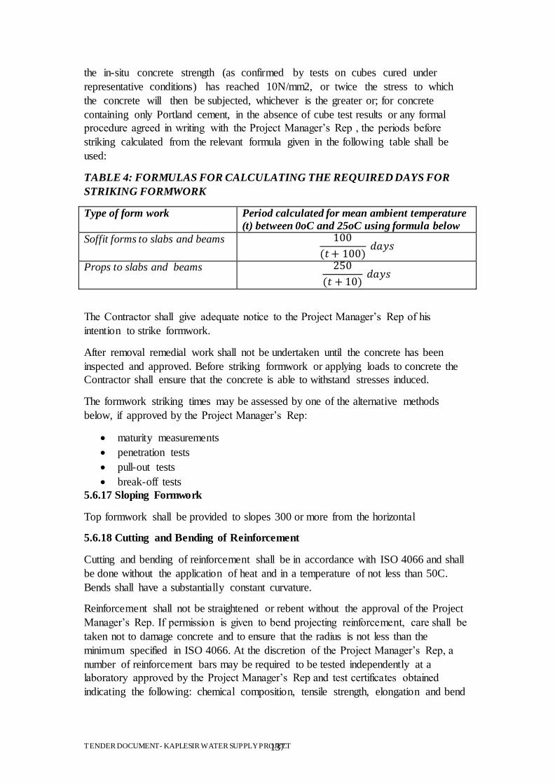
TENDER DOCUMENT- KAPLESIR WATER SUPPLY PROJECT 137
the in-situ concrete strength (as confirmed by tests on cubes cured under
representative conditions) has reached 10N/mm2, or twice the stress to which
the concrete will then be subjected, whichever is the greater or; for concrete
containing only Portland cement, in the absence of cube test results or any formal
procedure agreed in writing with the Project Manager‟s Rep , the periods before
striking calculated from the relevant formula given in the following table shall be
used:
TABLE 4: FORMULAS FOR CALCULATING THE REQUIRED DAYS FOR
STRIKING FORMWORK
Type of form work Period calculated for mean ambient temperature
(t) between 0oC and 25oC using formula below
Soffit forms to slabs and beams
Props to slabs and beams
The Contractor shall give adequate notice to the Project Manager‟s Rep of his
intention to strike formwork.
After removal remedial work shall not be undertaken until the concrete has been
inspected and approved. Before striking formwork or applying loads to concrete the
Contractor shall ensure that the concrete is able to withstand stresses induced.
The formwork striking times may be assessed by one of the alternative methods
below, if approved by the Project Manager‟s Rep:
maturity measurements
penetration tests
pull-out tests
break-off tests
5.6.17 Sloping Formwork
Top formwork shall be provided to slopes 300 or more from the horizontal
5.6.18 Cutting and Bending of Reinforcement
Cutting and bending of reinforcement shall be in accordance with ISO 4066 and shall
be done without the application of heat and in a temperature of not less than 50C.
Bends shall have a substantially constant curvature.
Reinforcement shall not be straightened or rebent without the approval of the Project
Manager‟s Rep. If permission is given to bend projecting reinforcement, care shall be
taken not to damage concrete and to ensure that the radius is not less than the
minimum specified in ISO 4066. At the discretion of the Project Manager‟s Rep, a
number of reinforcement bars may be required to be tested independently at a
laboratory approved by the Project Manager‟s Rep and test certificates obtained
indicating the following: chemical composition, tensile strength, elongation and bend
TENDER DOCUMENT- KAPLESIR WATER SUPPLY PROJECT 138
test values. To this end, the Contractor may be required to supply an extra bar of each
diameter for three different shape codes.
5.6.19 Fixing of Reinforcement
Reinforcement shall be firmly supported in position and secured against displacement.
Non-structural connections for the positioning of reinforcement shall be made with
tying wire or other fixing devices. Precautions shall be taken to ensure that projecting
ends of ties or clips do not encroach into the concrete cover.
Reinforcement shall be held in position during the placing of concrete by use of
distance pieces, spacers or other methods approved by the Project Manager‟s Rep.
Only approved spacers may be used in permanent works. Before spacers are approved
for use in the works, their capacity to hold the reinforcement securely in position
during concreting without detriment to concrete placement, compaction or durability
shall be fully demonstrated.
Links shall be taut so that bars are braced and the inside of their curved parts shall be
in contact with the bars being connected.
Partially-set concrete adhering to exposed bars during concreting operations shall be
removed.
5.6.20 Surface Condition of Reinforcement
Concrete shall not be placed until reinforcement is free from any substance which
might adversely affect the steel or concrete chemically or reduce the bond.
5.6.21 Laps and Joints
Laps and joints in reinforcement shall be made only at the positions described
and detailed in the construction documentation, reviewed by the Project Manager‟s
Rep .
5.6.22 Welding of Reinforcement
Reinforcement shall not be welded on Site except where described in or
permitted in the Contract Documentation. All welding procedures shall be subject to
the prior approval of the Project Manager‟s Rep in writing.
5.6.23 Built-in Items
Where pipes, sleeves, water bars or other items are built into concrete, they shall be
rigidly secured in position to prevent movement and shall be free from external
coatings which might reduce the bond. The Contractor shall take precautions to
prevent the formation or air pockets, voids or other defects whilst the concrete is
being placed.
5.6.24 Construction Joints
Contraction joints shall be made only at the positions described and detailed in the
construction documentation, as reviewed by the Project Manager‟s Rep .Joint lines
shall be arranged to coincide wherever possible with features of the finished work.
TENDER DOCUMENT- KAPLESIR WATER SUPPLY PROJECT 139
Concrete placing shall not be interrupted except where joints occur, and shall continue
after normal hours if necessary to achieve this.
Concrete shall not be allowed to taper off to a thickness of less than 50mm. Vertical
joints shall be formed against a stop board suitably notched to accommodate the
reinforcement. The top surface of each lift of concrete shall be straight and level
unless described otherwise in the Contract.
Where a kicker is used, it shall be at least 70mm high and shall be cast monolithically
with the previous concrete.
The surface of any concrete against which new concrete is to be cast shall be free
from laitance and shall be roughened to the extent that the large aggregate is exposed
but not disturbed. The joint surface shall be cleaned immediately before the fresh
concrete is placed against it.
Where practicable, such preparation of joints shall be carried out when the concrete
has set but not hardened. Construction joints shall be located and the sequence of
placing arranged as approved to minimize shrinkage and thermal strains to the
concrete.
Upon removal of the formwork the joint face shall be inspected, and if the soundness
of the concrete is not approved by the Project Manager‟s Rep the Contractor shall
investigate and remedy defects.
Where a design joint includes a continuous waterstop, concrete shall be well worked
around the embedded part of the waterstop and be free from honeycombing.
Projecting portions of the waterstop shall be protected from damage during operations
and, in the case of rubber and plastic, from light and heat.
To minimise leakage at construction joints in water retaining structures adjacent
panels shall be concreted within 3 days. If this is not achieved the procedure for
bonding new concrete to old shall be adopted.
Where it is necessary to bond new concrete to old, the bonding agent to be used shall
be an epoxy based bonding agent used in accordance with the manufacturer‟s
instructions. The existing concrete surface shall first be wire brushed or hacked and
cleaned to remove all dirt, dust, loose material and laitance and
to expose the aggregate. If oil or grease has affected any area this shall be removed by
chipping away down to unaffected material.
8.6.25 Surface Finishes Produced Without Formwork
Screeded Finish: The concrete shall be levelled and screeded to produce a uniform
plain or ridged surface as required. No further work shall be applied to the surface
unless it is a first stage for a Wood Float or Steel Trowel Finish.
Wood Float Finish: The Screeded Finish shall be wood floated under light pressure
to eliminate surface irregularities.
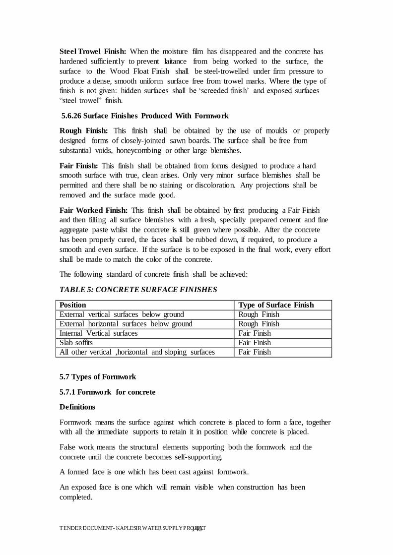
TENDER DOCUMENT- KAPLESIR WATER SUPPLY PROJECT 140
Steel Trowel Finish: When the moisture film has disappeared and the concrete has
hardened sufficiently to prevent laitance from being worked to the surface, the
surface to the Wood Float Finish shall be steel-trowelled under firm pressure to
produce a dense, smooth uniform surface free from trowel marks. Where the type of
finish is not given: hidden surfaces shall be „screeded finish‟ and exposed surfaces
“steel trowel” finish.
5.6.26 Surface Finishes Produced With Formwork
Rough Finish: This finish shall be obtained by the use of moulds or properly
designed forms of closely-jointed sawn boards. The surface shall be free from
substantial voids, honeycombing or other large blemishes.
Fair Finish: This finish shall be obtained from forms designed to produce a hard
smooth surface with true, clean arises. Only very minor surface blemishes shall be
permitted and there shall be no staining or discoloration. Any projections shall be
removed and the surface made good.
Fair Worked Finish: This finish shall be obtained by first producing a Fair Finish
and then filling all surface blemishes with a fresh, specially prepared cement and fine
aggregate paste whilst the concrete is still green where possible. After the concrete
has been properly cured, the faces shall be rubbed down, if required, to produce a
smooth and even surface. If the surface is to be exposed in the final work, every effort
shall be made to match the color of the concrete.
The following standard of concrete finish shall be achieved:
TABLE 5: CONCRETE SURFACE FINISHES
Position Type of Surface Finish
External vertical surfaces below ground Rough Finish
External horizontal surfaces below ground Rough Finish
Internal Vertical surfaces Fair Finish
Slab soffits Fair Finish
All other vertical ,horizontal and sloping surfaces Fair Finish
5.7 Types of Formwork
5.7.1 Formwork for concrete
Definitions
Formwork means the surface against which concrete is placed to form a face, together
with all the immediate supports to retain it in position while concrete is placed.
False work means the structural elements supporting both the formwork and the
concrete until the concrete becomes self-supporting.
A formed face is one which has been cast against formwork.
An exposed face is one which will remain visible when construction has been
completed.
TENDER DOCUMENT- KAPLESIR WATER SUPPLY PROJECT 141
5.7.2 Construction of formwork and falsework
Before construction begins, the Contractor shall submit to the Engineer, drawings
showing details of the proposed formwork and false work.
Formwork and false work shall be so constructed that they will support the loads
imposed on them by the fresh concrete together with additional stresses imposed by
vibrating equipment and by construction traffic, so that after the concrete has
hardened the formed faces shall be in the positions shown on the drawings within the
tolerances set out in Clause 506.
Ground supports shall be properly founded on footings designed to prevent
settlement.
Joints in formwork for exposed faces shall, unless otherwise specified, be evenly
spaced and horizontal or vertical and shall be continuous or form a regular pattern.
All joints in formwork including formwork for construction joints shall be tight
against the escape of cement, water and fines. Where reinforcement projects through
formwork, the form shall fit closely round the bars.
Formwork shall be so designed that it may be easily removed from the work without
damage to the faces of the concrete. It shall also incorporate provisions for making
minor adjustments in position if required, to ensure the correct location of concrete
faces. Due allowance shall be made in the position of all formwork for movement
and settlement under the weight of fresh concrete.
Where overhangs in formwork occur, means shall be provided to permit the escape of
air and to ensure that the space is filled completely with fully compacted concrete.
Formwork shall be provided for concrete surfaces at slopes of 30 degrees to the
horizontal or steeper. Surfaces at slopes less than 20 degrees may be formed by
screeding. Surfaces at slopes between 20 degrees and 30 degrees shall generally be
formed unless the Contractor can demonstrate to the satisfaction of the Engineer that
such slopes can be screeded with the use of special screed boards to hold the concrete
in place during vibration.
Horizontal or inclined formwork to the upper surface of concrete shall be adequately
secured against uplift due to the pressure of fresh concrete. Formwork to voids within
the body of the concrete shall also be tied down or otherwise secured against floating.
The internal and external angles on concrete surfaces shall be formed with fillets and
chamfers of the sizes shown on the drawings unless otherwise instructed by the
Engineer.
Supports for formwork for non-water retaining structures may be bolted to previously
placed concrete provided the type of bolt used is acceptable to the Engineer. If metal
ties through the concrete are used in conjunction with bolts, the metal left in shall not
be closer than 50mm to the face of the concrete.
Supports for formwork for water retaining structures may be bolted to previously
placed concrete provided the type of bolts and positions of fixing are acceptable to the
TENDER DOCUMENT- KAPLESIR WATER SUPPLY PROJECT 142
Engineer. After concreting the Contractor shall remove all support bolts and seal all
holes with well rammed cement/sand mortar containing approved waterproofing
cement additive. Metal ties which would be left in the concrete shall not be
permitted.
Formwork shall not be re-used after it has suffered damage which in the opinion of
the Engineer is sufficient to impair the finished surfaces of the concrete.
Where circumstances prevent easy access within the form for cleaning and inspection,
temporary openings for this purpose shall be provided through the formwork.
Shear keys shall be provided in all construction joints of the size and shape indicated
on the drawings.
Where precast concrete elements are specified for use as permanent formwork, or
proposed by the Contractor and agreed by the Engineer, they shall comply with the
requirements of the Specification. Such elements shall be set true to line and level
within the tolerances prescribed for the appropriate class of finish in Clause 506 and
fixed so that they cannot move when concrete is placed against them.
5.7.3 Preparation of formwork
Before any reinforcement is placed into position within formwork, the latter shall be
thoroughly cleaned and then dressed with a release agent. The agent shall be either a
suitable oil incorporating a wetting agent, an emulsion of water suspended in oil or a
low viscosity oil containing chemical agents. The Contractor shall not use an
emulsion of oil suspended in water nor any release agent which causes staining or
discoloration of the concrete, air holes on the concrete surface, or retards the set of the
concrete.
In order to avoid colour difference on adjacent concrete surfaces, only one type of
release agent shall be used in any one section of the works.
In cases where it is necessary to fix reinforcement before placing formwork, all
surface preparation of formwork shall be carried out before it is placed into position.
The Contractor shall not allow reinforcement or prestressing tendons to be
contaminated with formwork release agent.
Before placing concrete all dirt, construction debris and other foreign matter shall be
removed completely from within the placing area.
Before concrete placing commences, all wedges and other adjusting devices shall be
secured against movement during concrete placing and the Contractor shall maintain a
watch on the formwork during placing to ensure that no movement occurs.
5.7.4 Removal of formwork
Formwork shall be carefully removed without shock or disturbance to the concrete.
No formwork shall be removed until the concrete has gained sufficient strength to
withstand safely any stresses to which it may thereby be subjected.
TENDER DOCUMENT- KAPLESIR WATER SUPPLY PROJECT 143
The minimum periods which shall elapse between completion of placing concrete and
removal of forms are given in Table 5.1 and apply to ambient temperatures higher
than 10 degrees centigrade. At lower temperatures or if cement other than ordinary
Portland are involved, the Engineer may instruct that longer periods be used.
Alternatively, formwork may be removed when the concrete has attained the strength
set out in Table 5.1, provided that the attained strength is determined by making test
cubes and curing them under the same conditions as the concrete to which they refer.
Compliance with these requirements shall not relieve the Contractor of his obligation
to delay removal of formwork until the removal can be completed without damage to
the concrete.
Table 6 - MINIMUM PERIODS FOR FORMWORK REMOVAL
Position of Formwork Min. period for
temp over 10 degrees Centigrade
Strength to
be attained
Vertical or near vertical faces of mass concrete
24 hours 0.2 C
Vertical or near vertical faces of reinforced walls, beams and columns
48 hours 0.3 C
Underside of arches, beams and slabs (formwork only)
4 days 0.5 C
Supports to underside of arches, beams and slabs
14 days C
Arched linings in tunnels and underground
works
24 hours 4 N/mm2
Note: C is the nominal strength for the class of concrete used.
If the Contractor wishes to strip formwork from the underside of arches, beams and
slabs before the expiry of the period for supports set out above, it shall be designed so
that it can be removed without disturbing the supports. The Contractor shall not
remove supports temporarily for the purpose of stripping formwork and subsequently
replace them.
As soon as the formwork has been removed, bolt holes in concrete faces other than
construction joints which are not required for subsequent operations shall be
completely filled with mortar sufficiently dry to prevent any slumping at the face.
The mortar shall be mixed in the same proportions as the fine
aggregate and cement in the surrounding concrete and with the same materials and
shall be finished flush with the face of the concrete.
TENDER DOCUMENT- KAPLESIR WATER SUPPLY PROJECT 144
5.7.5 Surface finishes on formed surfaces
Classes of finish
The surface finish to be achieved on formed concrete surfaces shall be as shown on
the drawings and defined hereunder:
a) Class F1 finish
This finish is for surfaces against which backfill or further concrete will be placed.
Formwork may be sawn boards, sheet metal or any other suitable material which will
prevent the loss of fine material from the concrete being placed.
b) Class F2 finish
This finish is for surfaces which are permanently exposed to view but where the
highest standard of finish is not required. Forms to provide a Class F2 finish shall be
faced with wrought thicknessed tongued and grooved boards with square edges
arranged in a uniform pattern and close jointed or with suitable sheet material. The
thickness of boards or sheets shall be such that there shall be no visible deflection
under the pressure exerted by the concrete placed against them. Joints between
boards or panels shall be horizontal and vertical unless otherwise directed. This finish
shall be such as to require no general filling of surface pitting, but fins, surface
discoloration and other minor defects shall be remedied by methods agreed by the
Engineer.
c) Class F3 finish
This finish is for surfaces which will be in contact with water flowing at high velocity,
and for surfaces prominently exposed to view where good appearance is of special
importance. To achieve this finish, which shall be free of board marks, the formwork
shall be faced with plywood complying with B.S. 1088 or equivalent material in large
sheets. The sheets shall be arranged in an approved pattern. Wherever possible, joints
between sheets shall be arranged to coincide with architectural features or changes in
direction of the surface.
All joints between panels shall be vertical and horizontal unless otherwise directed.
Suitable joints shall be provided between sheets to maintain accurate alignment in the
plane of the sheets. Unfaced wrought boarding or standard steel panels will not be
permitted for Class F3 finish. The Contractor shall ensure that the surface is protected
from rust marks, spillages and stains of all kinds.
d) Curved surfaces
For curved surfaces where F2 or F3 finishes are called for, the formwork face shall be
built up of splines cut to make a tight surface which shall then be dressed to produce
the required finish.
Alternatively, single curvature surfaces may be faced with plastic or plywood linings
attached to the backing with adhesive or with escutcheon pins driven flush. Linings
shall not bulge, wrinkle or otherwise deform when subjected to temperature and
moisture changes.
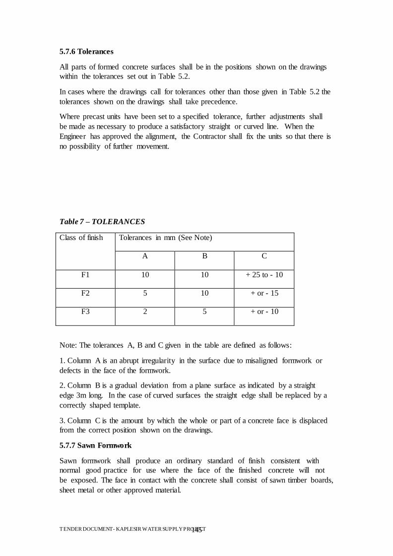
TENDER DOCUMENT- KAPLESIR WATER SUPPLY PROJECT 145
5.7.6 Tolerances
All parts of formed concrete surfaces shall be in the positions shown on the drawings
within the tolerances set out in Table 5.2.
In cases where the drawings call for tolerances other than those given in Table 5.2 the
tolerances shown on the drawings shall take precedence.
Where precast units have been set to a specified tolerance, further adjustments shall
be made as necessary to produce a satisfactory straight or curved line. When the
Engineer has approved the alignment, the Contractor shall fix the units so that there is
no possibility of further movement.
Table 7 – TOLERANCES
Class of finish Tolerances in mm (See Note)
A
B C
F1
10 10 + 25 to - 10
F2
5 10 + or - 15
F3
2 5 + or - 10
Note: The tolerances A, B and C given in the table are defined as follows:
1. Column A is an abrupt irregularity in the surface due to misaligned formwork or
defects in the face of the formwork.
2. Column B is a gradual deviation from a plane surface as indicated by a straight
edge 3m long. In the case of curved surfaces the straight edge shall be replaced by a
correctly shaped template.
3. Column C is the amount by which the whole or part of a concrete face is displaced
from the correct position shown on the drawings.
5.7.7 Sawn Formwork
Sawn formwork shall produce an ordinary standard of finish consistent with
normal good practice for use where the face of the finished concrete will not
be exposed. The face in contact with the concrete shall consist of sawn timber boards,
sheet metal or other approved material.
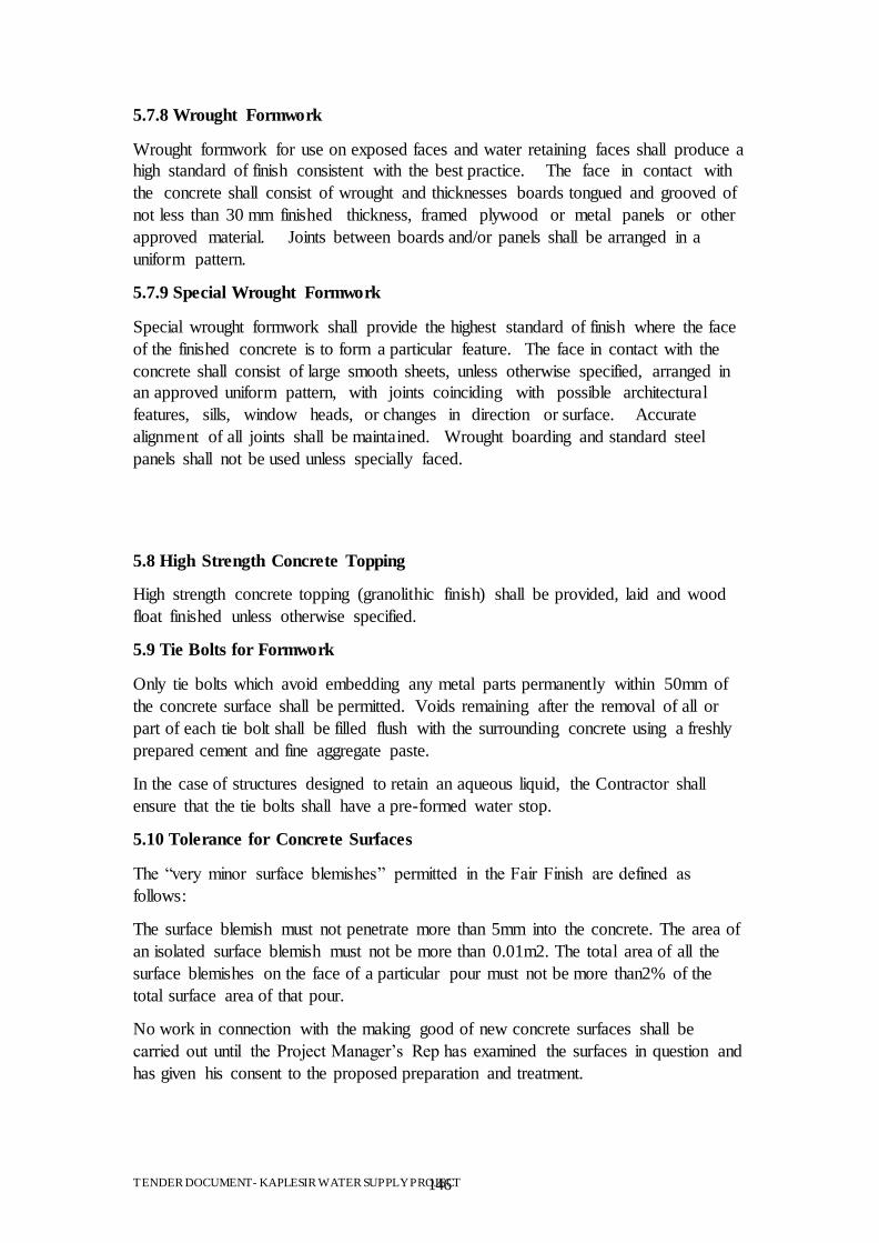
TENDER DOCUMENT- KAPLESIR WATER SUPPLY PROJECT 146
5.7.8 Wrought Formwork
Wrought formwork for use on exposed faces and water retaining faces shall produce a
high standard of finish consistent with the best practice. The face in contact with
the concrete shall consist of wrought and thicknesses boards tongued and grooved of
not less than 30 mm finished thickness, framed plywood or metal panels or other
approved material. Joints between boards and/or panels shall be arranged in a
uniform pattern.
5.7.9 Special Wrought Formwork
Special wrought formwork shall provide the highest standard of finish where the face
of the finished concrete is to form a particular feature. The face in contact with the
concrete shall consist of large smooth sheets, unless otherwise specified, arranged in
an approved uniform pattern, with joints coinciding with possible architectural
features, sills, window heads, or changes in direction or surface. Accurate
alignment of all joints shall be maintained. Wrought boarding and standard steel
panels shall not be used unless specially faced.
5.8 High Strength Concrete Topping
High strength concrete topping (granolithic finish) shall be provided, laid and wood
float finished unless otherwise specified.
5.9 Tie Bolts for Formwork
Only tie bolts which avoid embedding any metal parts permanently within 50mm of
the concrete surface shall be permitted. Voids remaining after the removal of all or
part of each tie bolt shall be filled flush with the surrounding concrete using a freshly
prepared cement and fine aggregate paste.
In the case of structures designed to retain an aqueous liquid, the Contractor shall
ensure that the tie bolts shall have a pre-formed water stop.
5.10 Tolerance for Concrete Surfaces
The “very minor surface blemishes” permitted in the Fair Finish are defined as
follows:
The surface blemish must not penetrate more than 5mm into the concrete. The area of
an isolated surface blemish must not be more than 0.01m2. The total area of all the
surface blemishes on the face of a particular pour must not be more than2% of the
total surface area of that pour.
No work in connection with the making good of new concrete surfaces shall be
carried out until the Project Manager‟s Rep has examined the surfaces in question and
has given his consent to the proposed preparation and treatment.
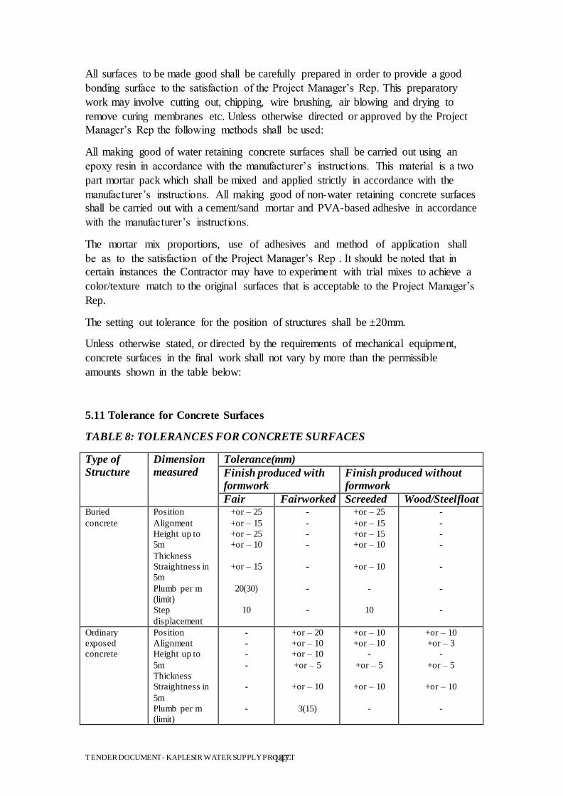
TENDER DOCUMENT- KAPLESIR WATER SUPPLY PROJECT 147
All surfaces to be made good shall be carefully prepared in order to provide a good
bonding surface to the satisfaction of the Project Manager‟s Rep. This preparatory
work may involve cutting out, chipping, wire brushing, air blowing and drying to
remove curing membranes etc. Unless otherwise directed or approved by the Project
Manager‟s Rep the following methods shall be used:
All making good of water retaining concrete surfaces shall be carried out using an
epoxy resin in accordance with the manufacturer‟s instructions. This material is a two
part mortar pack which shall be mixed and applied strictly in accordance with the
manufacturer‟s instructions. All making good of non-water retaining concrete surfaces
shall be carried out with a cement/sand mortar and PVA-based adhesive in accordance
with the manufacturer‟s instructions.
The mortar mix proportions, use of adhesives and method of application shall
be as to the satisfaction of the Project Manager‟s Rep . It should be noted that in
certain instances the Contractor may have to experiment with trial mixes to achieve a
color/texture match to the original surfaces that is acceptable to the Project Manager‟s
Rep.
The setting out tolerance for the position of structures shall be ±20mm.
Unless otherwise stated, or directed by the requirements of mechanical equipment,
concrete surfaces in the final work shall not vary by more than the permissible
amounts shown in the table below:
5.11 Tolerance for Concrete Surfaces
TABLE 8: TOLERANCES FOR CONCRETE SURFACES
Type of
Structure
Dimension
measured
Tolerance(mm)
Finish produced with
formwork
Finish produced without
formwork
Fair Fairworked Screeded Wood/Steelfloat Buried
concrete Position
Alignment
Height up to
5m
Thickness
Straightness in
5m
Plumb per m
(limit)
Step
displacement
+or – 25
+or – 15
+or – 25
+or – 10
+or – 15
20(30)
10
-
-
-
-
-
-
-
+or – 25
+or – 15
+or – 15
+or – 10
+or – 10
-
10
-
-
-
-
-
-
-
Ordinary
exposed
concrete
Position
Alignment
Height up to
5m
Thickness
Straightness in
5m
Plumb per m
(limit)
-
-
-
-
-
-
+or – 20
+or – 10
+or – 10
+or – 5
+or – 10
3(15)
+or – 10
+or – 10
-
+or – 5
+or – 10
-
+or – 10
+or – 3
-
+or – 5
+or – 10
-
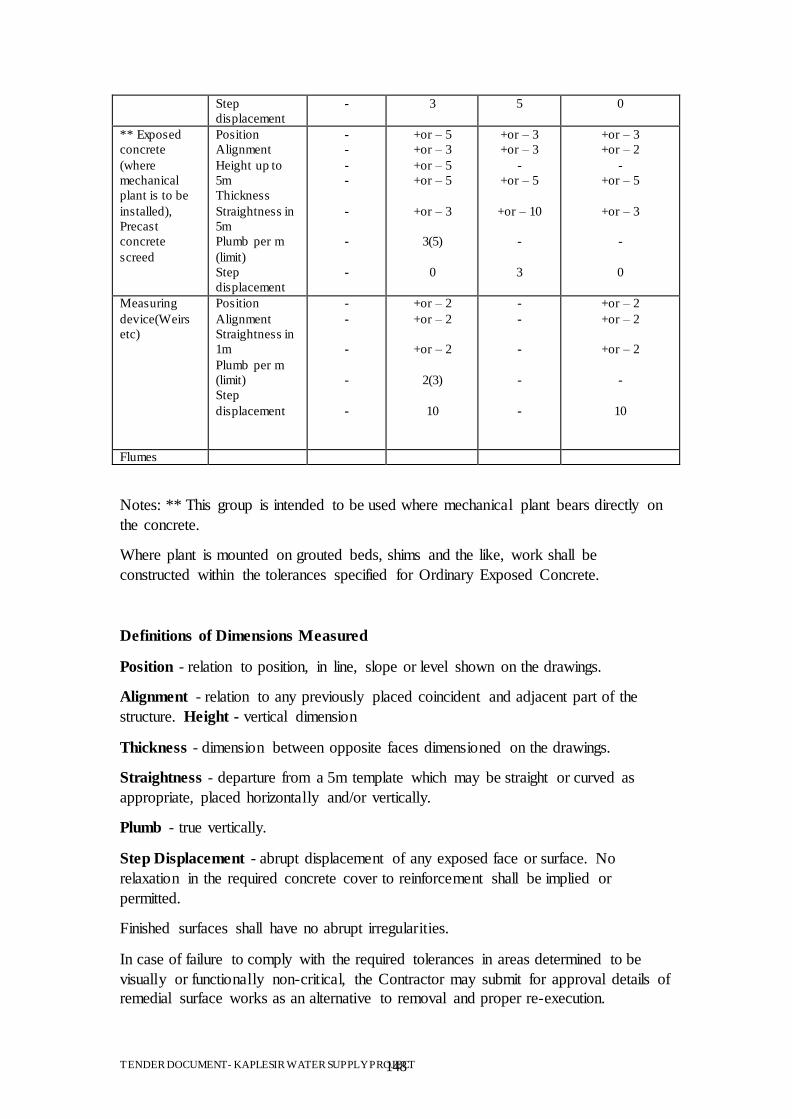
TENDER DOCUMENT- KAPLESIR WATER SUPPLY PROJECT 148
Step
displacement
- 3 5 0
** Exposed
concrete
(where
mechanical
plant is to be
installed),
Precast
concrete
screed
Position
Alignment
Height up to
5m
Thickness
Straightness in
5m
Plumb per m
(limit)
Step
displacement
-
-
-
-
-
-
-
+or – 5
+or – 3
+or – 5
+or – 5
+or – 3
3(5)
0
+or – 3
+or – 3
-
+or – 5
+or – 10
-
3
+or – 3
+or – 2
-
+or – 5
+or – 3
-
0
Measuring
device(Weirs
etc)
Position
Alignment
Straightness in
1m
Plumb per m
(limit)
Step
displacement
-
-
-
-
-
+or – 2
+or – 2
+or – 2
2(3)
10
-
-
-
-
-
+or – 2
+or – 2
+or – 2
-
10
Flumes
Notes: ** This group is intended to be used where mechanical plant bears directly on
the concrete.
Where plant is mounted on grouted beds, shims and the like, work shall be
constructed within the tolerances specified for Ordinary Exposed Concrete.
Definitions of Dimensions Measured
Position - relation to position, in line, slope or level shown on the drawings.
Alignment - relation to any previously placed coincident and adjacent part of the
structure. Height - vertical dimension
Thickness - dimension between opposite faces dimensioned on the drawings.
Straightness - departure from a 5m template which may be straight or curved as
appropriate, placed horizontally and/or vertically.
Plumb - true vertically.
Step Displacement - abrupt displacement of any exposed face or surface. No
relaxation in the required concrete cover to reinforcement shall be implied or
permitted.
Finished surfaces shall have no abrupt irregularities.
In case of failure to comply with the required tolerances in areas determined to be
visually or functionally non-critical, the Contractor may submit for approval details of
remedial surface works as an alternative to removal and proper re-execution.

TENDER DOCUMENT- KAPLESIR WATER SUPPLY PROJECT 149
In case of failure to comply with the required tolerances in visually or functionally
critical areas, out of tolerance work shall be removed and properly re-executed as
provided in the Contract.
5.12 Grout Quality Control Testing
Grout is specified by nominal mixes, unless specified elsewhere in the Contract.
8.13 Marking of Precast Concrete Components
Where appropriate, indelible identification and orientation marks shall be put on all
precast concrete components in such a position that the marks shall not show or be
exposed in the finished work.
5.14 Concrete Testing
Testing may be carried out to any recognized appropriate set of standards, provided
that consistency in the application of the standards is ensured. The limits of
acceptance shall, however, be as defined herein relative to the specified standard.
Sampling and testing shall be in accordance with the relevant sections of EN 12350 or
BS 1881, the relevant following ISO, or as directed by the Project Manager‟s Rep.
ISO 1920 - dimensions, tolerances and applicability of test specimens; ISO 2736-1 -
test specimens part 1 - sampling of fresh concrete; ISO 2736-2 - test specimens part2 -
making and curing of test specimens for strength tests.
Ready mixed concrete shall be tested by the supplier as part of his quality control.
Copies of such test results shall be made available to the Project Manager‟s Rep on
request. Where concrete is mixed on site, or where records are not available from the
supplier, additional testing will be required on site as directed by the Project
Manager‟s Rep.
The Contractor shall be responsible for manufacturing, transporting, storing, curing
and testing of concrete cubes required to ensure compliance of mixes as specified.
5.15 Quality and Testing
Sampling for test purposes shall comply with ISO 2736/1 (on site) and BS 1881 Part
125 (in Laboratory). The making and curing of specimens shall comply with ISO
1920 and ISO 2736/2.
Cubes shall be 150mm size and tested to BS 1881 Part 116.
The cubes shall be tested by a laboratory which has third party accreditation for
compressive strength testing of concrete.
5.16 Sampling Cubes
The rate of concrete sampling shall be as follows. At least one sample of concrete
shall be taken from each grade and type of structural concrete each day.
TABLE 9: NUMBER OF SAMPLES FOR CONCRETE BLOCKS
Type of structure Sample to represent a volume of (m3)
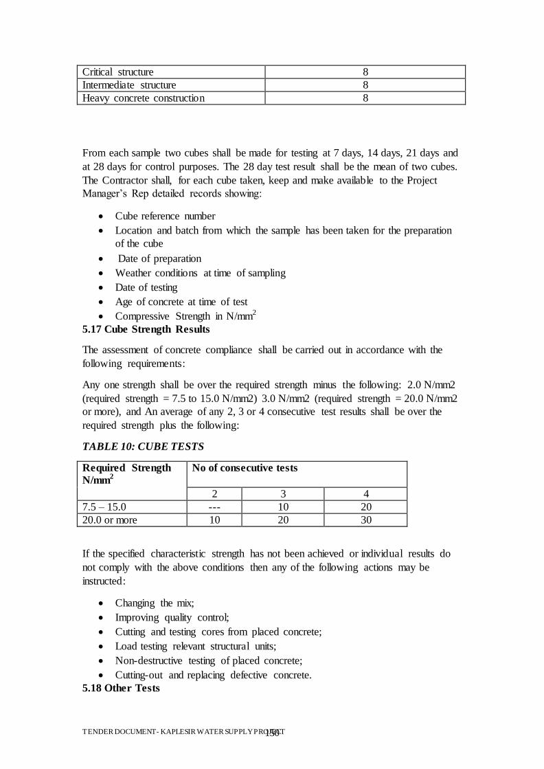
TENDER DOCUMENT- KAPLESIR WATER SUPPLY PROJECT 150
Critical structure 8
Intermediate structure 8
Heavy concrete construction 8
From each sample two cubes shall be made for testing at 7 days, 14 days, 21 days and
at 28 days for control purposes. The 28 day test result shall be the mean of two cubes.
The Contractor shall, for each cube taken, keep and make available to the Project
Manager‟s Rep detailed records showing:
Cube reference number
Location and batch from which the sample has been taken for the preparation
of the cube
Date of preparation
Weather conditions at time of sampling
Date of testing
Age of concrete at time of test
Compressive Strength in N/mm2
5.17 Cube Strength Results
The assessment of concrete compliance shall be carried out in accordance with the
following requirements:
Any one strength shall be over the required strength minus the following: 2.0 N/mm2
(required strength = 7.5 to 15.0 N/mm2) 3.0 N/mm2 (required strength = 20.0 N/mm2
or more), and An average of any 2, 3 or 4 consecutive test results shall be over the
required strength plus the following:
TABLE 10: CUBE TESTS
Required Strength
N/mm2
No of consecutive tests
2 3 4
7.5 – 15.0 --- 10 20
20.0 or more 10 20 30
If the specified characteristic strength has not been achieved or individual results do
not comply with the above conditions then any of the following actions may be
instructed:
Changing the mix;
Improving quality control;
Cutting and testing cores from placed concrete;
Load testing relevant structural units;
Non-destructive testing of placed concrete;
Cutting-out and replacing defective concrete.
5.18 Other Tests
TENDER DOCUMENT- KAPLESIR WATER SUPPLY PROJECT 151
Compaction factor (EN 12350-5, ISO 4111), slump (EN 12350-2, ISO 4109), Vebe
(EN 12350-3, ISO 4110) or other workability tests shall be carried out as required
during concreting of permanent works to control workability at the batching plant and
at the site of the pour. The degree of workability shall be as for the trial mixes.
5.19 Contamination
Concrete shall be protected from contamination by sea or brackish water, oil, fuel and
other deleterious materials for a minimum period of 30 days after placing.
5.20 Protection of Joints
Rebates formed to receive sealant and the surfaces of construction joints shall be
protected from curing compound by wet hessian to ensure proper curing of the joint
surface and adjacent concrete. The protection shall remain in place until the joint
surface is sealed.
5.21 Specimen Panels of Concrete
If required, the Contractor shall produce specimen panels of finished concrete for
approval.
5.22 Benching
Where benching is used the minimum thickness will be 40mm.
6 REPAIR OF EXISTING CONCRETE
In case of repair works to existing concrete structures being necessary the following
procedures shall be adhered to.
6.1 Dewatering and cleaning
All repair work to existing concrete shall be carried out in the dry. The Contractor
shall therefore dewater the concerned structures and clean the surfaces from all
sediment, algae, bushes, stones, trash and all other foreign matter to the satisfaction of
theProject Manager‟s Rep.
6.2 Identification of repairs
After cleaning the concrete from any foreign matter the Contractor shall survey the
exposed surfaces and make an inventory of the work to be done distinguishing the
types of defects as described in this Section and submit the inventory of proposed
work to the Project Manager‟s Rep for approval. In a joint survey of the Project
Manager‟s Rep and the Contractor the inventory will be discussed and the Project
Manager‟s Rep may instruct the Contractor to make modifications in the inventory of
proposed work after which modifications the Project Manager‟s Rep shall approve the
inventoryfor execution. The Contractor shall furnish the Project Manager‟s Rep with
three (3) signed copies of the inventory of proposed work for approval to the Project
Manager‟s Rep and after approval the Project Manager‟s Rep shall sign these copies
and return one (1) signed copy to the Contractor. The Contractor will execute the
work accordingly and in accordance with these Specifications.
TENDER DOCUMENT- KAPLESIR WATER SUPPLY PROJECT 152
6.3 Materials
General
For all mortars, grouts, resins and other products described in this section, the
Contractor shall propose the pro- ducts he intends to use in the Works and shall
submit to the Project Manager‟s Rep for approval full information on these pro- ducts.
All products shall have no adverse effects on potable water.
Products named elsewhere in this section are an indication of the standard type and
workmanship of goods which are satisfactory to the Project Manager‟s Rep. The
Contractor may use named products or equivalent other products after the approval of
the Project Manager‟s Rep in accordance with the Specifications, Conditions of
Contract and with the manufacturers specifications.
Water, Steel and Aggregate
Water for use in mortars and concrete shall comply with the requirements described in
Clause "Water". Reinforcement steel shall in all respects comply with the
requirements described in Clause "Reinforcement Steel".
Sand or other aggregate for mixing with grout shall comply with the requirements for
fine aggregate described in the Clause "Aggregate".
6.4 Types of defects
For the purpose of repairs to existing concrete the following defects shall be
distinguished:
Cracks 1 up to 3 mm wide
Leaking Cracks 1 up to 3 mm wide
Cracks 3 up to 20 mm wide
Defective Concrete as loose, broken or honeycombed concrete
Deteriorated Joints
Voids under Concrete Slabs
6.5 Repair of cracks 1 up to 3 mm wide
The Contractor shall repair cracks in structural concrete by injection with an
appropriate injection resin.
When the cracks are dry an epoxy resin of low viscosity shall be used. In other cases
injection shall be done with a low viscosity polyurethane resin.
The Contractor shall first blow, clean, oil free compressed air through the crack
before any resin in injected in order to remove as much as possible any dust or grit
that may obstruct the flow.
When the crack is cleaned, a superficial seal will be applied at the surface of the
member by using a fast setting material such as any appropriate polyester resin, in
which injection nipples are fixed at intervals. The most satisfactory spacing of the
injection nipples shall be found by experience, but is usually less than the estimated
depth of the crack. The most suitable pressure for injection the resin shall also be
TENDER DOCUMENT- KAPLESIR WATER SUPPLY PROJECT 153
found by experience. The spacing and pressure are to be to the satisfaction of the
Project Manager‟s Rep.
Injection shall be done by an approved and established epoxy resin injection system.
Epoxy injection resin of low viscosity shall be subject to the approval of the Project
Manager‟s Rep. No injection shall be done without the approval of the Project
Manager‟s Rep.
6.6 Repair of leaking cracks 1 up to 3 mm wide
Repair by Injection
The Contractor shall inject leaking joints with waterstops in structures with a suitable
polyurethane injection resin.
The polyurethane injection resin shall be of low viscosity and reacting with water as
to fill all cavities in and adjacent to the joint. Injection shall continue until all leaks
are stopped.
To relieve the water pressure if necessary, drain pipes shall be fixed into the
remaining concrete so that the water can discharge freely. After the injection material
has hardened, the drain pipes shall be cut off or removed and the remaining holes will
be plugged one by one with a very quicksetting material that can be held in place by
hand until it has set. The Contractor shall submit for approval to the Project
Manager‟s Rep the method of injection, material and equipment he proposes to use.
The Project Manager‟s Rep may at his discretion instruct the Contractor to modify his
proposal in accordance with the instructions of the Project Manager‟s Rep. No
injection will be done without the approval of the Project Manager‟s Rep.
Repair by Lining
Concrete slabs featuring many leaks due to cracks and other small porosities of the
concrete shall be waterproofed by application of an internal lining. Slabs subjected to
variable direction of water pressure shall not be repaired with this method but only via
the method as described in Clause "Repair by Injection".
The lining shall be applied only on the inside of water retaining structures so that the
lining is compressed between water and concrete.
The lining shall be an epoxy resin and or cement based sealant. The material shall
have a durability of 25 years or more and provide a watertight and easy to clean
surface. The material shall be capable of bridging and filling 3 mm wide cracks under
the existing water pressures.
Particular care shall be taken to ensure all concrete surfaces are completely free from
algae, oil, dust, grease, corrosion and any other deleterious matter before application
of the lining.
6.7 Repair of cracks 3 up to 20 mm wide

TENDER DOCUMENT- KAPLESIR WATER SUPPLY PROJECT 154
The Contractor shall clean the crack from all dirt and other foreign matter and
roughen the surfaces mechanically. After cleaning the crack with oil free compressed
air the surfaces will be primed with an approved and established primer.
All exposed reinforcement shall be thoroughly cleaned from any loose rust or other
foreign matter. Exposed reinforcement shall be primed with an approved and
established primer, to prevent further corrosion.
If the reinforcement has broken or deteriorated too far the crack must be repaired as
described in Clause "Repair of Defective Concrete". Then the crack shall be filled
with a suitable, approved and established watertight non shrink grout and cured
directly after application with a curing agent.
6.8 Repair of defective concrete
When concrete has broken out, has become loose, shows honeycombing or any other
similar defects, it shall be removed and the affected member reconstructed to its
original section.
The Contractor shall remove all loose or deteriorated concrete until only sound
material is encountered. Concrete shall in any case be removed to 25 mm behind any
exposed reinforcement.
All exposed reinforcement shall be thoroughly cleaned from any loose rust or other
foreign matter. Exposed reinforcement shall be primed with an approved and
established primer, to prevent further corrosion.
If the reinforcement has broken or deteriorated too far, new reinforcement shall be
placed. To accommodate this reinforcement, holes shall be drilled in which the new
bars are fixed with an epoxy resin. As an alternative the surrounding sound concrete
can be broken out until sufficient lap length has been acquired to accommodate the
new bars. If neither option is suitable, an external steel or concrete bracing shall be
constructed. The final solution to be applied shall be approved by the Project
Manager‟s Rep.
Particular care shall be taken to ensure all exposed concrete surfaces are completely
free from laitance, oil, dust, grease, corrosion and any other deleterious matter.
Laitance shall be mechanically removed by high pressure water blasting, grit blasting
or a combination of both.
The edges of the repair area shall be sawn or cut to a depth of 10 mm to avoid feather
edging. All concrete surfaces shall be in a saturated surface dry condition prior to
priming.
Priming shall be done with an approved and established primer after which the broken
out area will be repaired with a suitable watertight non-shrink grout approved by the
Project Manager‟s Rep. Immediately after finishing the repair the mortar shall be
cured with a curing agent.
6.9 Repair of deteriorated joints
TENDER DOCUMENT- KAPLESIR WATER SUPPLY PROJECT 155
At contraction, construction or movement joints where the filler and or sealant has
deteriorated, replacement is required. Hereto the Contractor shall replace both the
joint filler and or the sealant. He shall cut out and remove the existing joint filler and
or sealant and clean the joint from vegetation, sediment and other foreign matter. The
edges of the concrete shall be square. If edges have broken up to 10 mm deep the new
joint filler shall be placed deeper. Broken edges from 10 to 30 mm shall be cut square
to give a square but wider joint. At edges broken deeper than 30 mm the concrete
shall be broken back till 25 mm behind the nearest reinforcement and repaired in
accordance with the clause“Repair of defective concrete”.
After clearing and squaring up the recess in the concrete the joints shall be filled with
flexible filler and or sealant. This shall comply with the requirements as described in
sub-clauses "Movement Joint Filler" and "Joint sealer".
Only in movement joints the following alternative construction may be used; a
vacuum tube of butyl rubber shall be placed in the joint and the voids left over shall
be filled with butyl putty. The vacuum tube and butyl putty shall be of an established
type and approved bytheProject Manager‟s Rep.
6.10 Repair of voids under concrete
During reparation of cracks or joints in otherwise sound slabs, hollow spaces may be
found behind the slabs. In such cases and where indicated bythe Project Manager‟s
Repthe Contractor shall fill the hollow spaces with a suitable cement based grout.
Depending on the type of joint, grouting shall be done either before or after
completing other repair works on the joints or cracks.
If the voids are not accessible through at least 10 mm wide joint rebates then holes
shall then be drilled through the concrete slab, with a maximum distance between
successive holes of 700 mm centre to centre. Through the holes the hollow spaces
shall be grouted. The grout will be subject to the approval of the Project Manager‟s
Repand shall be of a suitable viscosity.
The area to be grouted and working method will be proposed by the Contractor to the
approval of the Project Manager‟s Rep; or as instructed by the Project Manager‟s Rep.
No grouting or drilling shall be done without the approval of the Project Manager‟s
Rep.
7 .0 BLOCKWORK WALLS
7.1 General
All masonry work shall be constructed from building stone as specified in drawings.
For walls, facing and other exposed works the stone shall unless otherwise specified,
be medium chisel dressed from approved source.
7.2 Workmanship
The Contractor shall provide and use proper setting out rods for all work.
TENDER DOCUMENT- KAPLESIR WATER SUPPLY PROJECT 156
Stones shall be well soaked before use and the tops of walls shall be kept wet as the
work proceeds. The stones shall be properly bonded so that no vertical joint in a
course is within 115mm of a joint in the previous course. Alternate courses of walling
at angles and intersections shall be carried through the full thickness of the adjoining
walls. All perpends, reveals and other angles of the walling shall be built strictly true
and square.
The stones shall be bedded, jointed and pointed in mortar 1 to 3 in accordance with
Clause 707 with beds and joints 9mm thick flushed up and grouted solid as the work
proceeds.
All masonry work shall be cured in accordance with the relevant requirements of
Clause 406.
7.3 Cast stonework
Cast stone shall be as specified see 7.1 below. Facing stones shall be brought up in
courses to a height not exceeding 1 metre at a time, the concrete backing being then
brought up and well incorporated into and round the backs of the stones and the
projecting metal ties to ensure a complete bond. The stones shall be bedded and
jointed as shown on the drawings.
All materials, moulds, mixing, casting and surface treatment, setting, jointing and
pointing, and all centering, scaffolding and labour required to complete the cast
stonework specified or as shown on the drawings, shall be included in the rates for
such work.
7.4 Precast concrete blocks
Precast concrete blocks shall be manufactured to BS 6073.
Blocks shall be either hollow or solid and the thickness of the blocks shall be as
indicated in the Drawings. The blocks shall have minimum compressive strength of
3.5. N/mm².
All blocks shall have a dense, even surface and a density of not less than 1700 kg/m³.
The Contractor shall submit samples of blocks for every batch brought to the Site to
the Project Manager‟s Rep for approval. The Contractor shall arrange strength tests
required by the Project Manager‟s Rep to be executed by a testing authority approved
by the Project Manager‟s Rep .
7.5 Mortar
Mortar for both masonry and block work shall be cement mortar consisting of one
part of ordinary Portland cement complying to BS 12 to four parts of sand by volume,
mixed with just sufficient water to make the mixture workable. No lime shall be
added to the mortar.
Natural sand shall be used in cement mortar unless otherwise approved. The sand
shall be obtained from sources approved by the Project.
TENDER DOCUMENT- KAPLESIR WATER SUPPLY PROJECT 157
Plasticisers, air entraining agents or other additives may be used in the mortar subject
to the approval of the Project Manager‟s Rep .
7.6 Storage of materials
Blocks shall be loaded and unloaded by hand and not tipped, and shall not be used
until 4 weeks after casting unless otherwise approved by the Project Manager‟s Rep .
All blocks shall be handled carefully from manufacture to laying and properly stacked
in position convenient for the work. They shall be kept free from standing water and
protected from rain, mud and contamination by other materials.
Sand shall be stored separately on clean hard dry standing and protected from
contamination.
Cement shall be stored off the ground under cover and away from damp, and in such
a manner as to enable it to be used in rotation in order of delivery and in accordance
with the requirements of Clause "Concrete Work", sub-clause "Supply".
7.7 Mortar mixing
All materials shall be accurately gauged by gauge boxes and mechanically mixed to a
uniform consistency. Mortars shall be used within 1 hour of the addition of cement
after which they shall be discarded. Re- tempering of mortar will not be permitted.
Gauge boxes and mixers shall be kept clean.
7.8 Block work
All block work unless otherwise specified shall comply with the recommendations of
BS 8000; Part 3; 1989 (Code of Practice for masonry). All surfaces on which block
work is to be built shall be clean from any foreign matter influencing the bond
between the surface and block work. The use of chipped or defaced blocks will not be
permitted in any face work. All work shall be built uniform, true and level, with all
perpends vertical and in line, all cross joints shall be solid, filled with mortar in every
course as the work proceeds.
All blocks shall be clean before placing and shall be moistened with water for at least
3 hours before using by a method which will ensure that each block is thoroughly and
uniformly wetted.
No work shall rise more than 1000 mm above the adjoining works and such risings
are to be properly racked back. No blockwork shall be carried up higher than 1500
mm in one day. Joints in walling to be
plastered or rendered shall be raked out 10 mm deep to form a key. All cross (vertical)
joints shall be filled by well buttering the ends of the block with mortar and then
sliding it against its neighbour.
TENDER DOCUMENT- KAPLESIR WATER SUPPLY PROJECT 158
Block work of single block thickness shall be laid in stretcher bond, and block work
of double block thickness in alternate courses of headers and stretchers. No broken
blocks will be accepted except where necessary for bonding. All blocks shall be cut
by means of a mechanical disc cutter.
Alternate courses of load bearing block walling at intersection shall be carried through
the full thickness the adjoining wall.
Course heights shall not vary throughout the building and each course shall be level
and set out so that bed joints occur in line with sills, lintels and other features.
Damp-proof Courses in Walls Damp-proof courses in walls shall be bituminous
damp-proof course to BS 743 weighing not less than 3.8 kg/m2 overlapped 75 mm at
all jointings and bedded in mortar whilst the mortar is still wet.
7.9 Protection
When constructing masonry or block work in unfavorable weather and in protecting
the finished work, the Contractor shall observe the same instructions as are specified
for concrete work.
All block work, including pointing, shall be cured by keeping the wall wet or moist
with a method as approved by the Project Manager‟s Rep .
7.10 Non load-bearing walls
All walls which are not load-bearing shall not be brought up to final finished level
until the construction of any reinforced concrete roof slabs has been completed and
the roof finishes have been installed.
7.11 Ties to concrete structures
Ties at junctions with reinforced concrete work shall be of the 'butterfly' type to BS
1243 and shall be cast into the concrete at such centers to be in line with the center of
the depth and width of mortar joints.
7.12 Movement joints
Movement joints shall comply with the requirements for movement joints in concrete
work as the described in these specifications.
8.0 STEEL WORK
8.1 General
The work under this Clause shall include as far as necessary the design of connections
and other details, manufacture, inspection and testing, delivery to Site, unloading
and where necessary storage at Site, complete erection, testing on completion and
setting to work, all to the satisfaction of the Project Manager‟s Rep .
The dimensions given on the drawings are based on available information or design.
The Contractor shall be responsible for checking actual dimensions of gates,
structures, etc. either existing or after construction against the dimensions given on
the drawings.
TENDER DOCUMENT- KAPLESIR WATER SUPPLY PROJECT 159
8.2 Standards for materials and workmanship
Unless otherwise approved, steel and other metal work shall comply with the
following British Standard
Specifications:
BS 4S Structural Steel Sections, Part 1, Hot-rolled sections;
BS 153 Steel Girder Bridges;
BS 639 Covered Electrodes for the Manual Metal-arc Welding
BS 709 Methods of Testing Welds;
BS 916 Black Bolts, Screws and Nuts;
BS 1775 Steel Tubes for Structures;
BS 1856 Metal-arc Welding of Mild Steels;
BS 4360 Weldable Structural Steels;
BS 5950 Structural Use of Steelwork in Buildings.
Fabrication and erection on Site shall be to the same standards as specified for work
off Site.
8.3 Materials
8.3.1 Steel
Unless otherwise specified all structural mild steel parts shall be manufactured from
steel Grade 43 A, or equivalent. The ultimate tensile stress shall not be less than 360
N/mm² and the yield stress shall not be less than 235 N/mm².
8.3.2 Sections
Steel sections can be cold formed or hot rolled.
8.3.3 Nuts, Bolts and Welding Electrodes
Unless specified otherwise, nuts and bolts shall have hexagonal heads, ISO metric
threads, comply with BS4190 and be of Grade 4.6 or Grade 43. High strength friction
grip bolts shall be of grade 8.8 or 10.9 and shall comply with BS 4395.
All bolts, nuts, washers shall be galvanized in accordance with BS 729. Where bolting
is incompatible with the material being fixed, suitable isolating washers and sleeves
shall be used. Metal washers shall comply with BS 4320.
All anchor bolts to cast in concrete shall not be less than M16. Bolts for structural
steelwork shall be not less than M12.
Bolt lengths shall be sufficient to ensure that nuts are full-threaded when tightened in
final position.
TENDER DOCUMENT- KAPLESIR WATER SUPPLY PROJECT 160
Welding electrodes for arc welding of grades of structural steel to BS 4360, shall be
low hydrogen type and shall comply with the requirements of BS 639.
8.4 Working drawings and method statement
Before fabrication commences the Contractor shall submit to the Project Manager‟s
Rep for his approval design calculations, working and shop drawings of the steel and
other metal work to be supplied under the contract. He shall also submit to the Project
Manager‟s Rep for approval of a detailed method statement describing the fabrication
methods to be used.
The Contractor shall be responsible for the correctness of his shop details and for shop
fittings and site connections.
8.5 Fabrication
8.5.1 Welding
Welding shall be metal-arc welding complying with the requirements of BS 1856 or
BS 5135, as appropriate. All welds shall be continuous unless specified otherwise. All
fillet welds shall approximate to the thickness of the thinnest member to the joint. All
parts shall have the edges accurately prepared to the appropriate profile for welding.
Welding shall be carried out only under the direction of an experienced and
competent supervisor and only certified welders qualified in this class of work shall
be employed. Welding procedures shall be such that residual stresses are minimal and
that distortion is avoided.
All fillet welding shall be tested by ultrasonic, crack detection, or other approved
means. For all items off steel work the Contractor shall allow for the cost of adequate
radiograph examination of the welds. The welds and positions to be examined will be
indicated by the Project Manager‟s Rep .
8.5.2 Bending
No straightening or flattening by bending or use of heat shall be carried out without
approval of the Project Manager‟s Rep and, if so approved such straightening or
flattening shall be carried out as specified by the Project Manager‟s Rep .
8.5.3 Cutting
Shearing or cropping shall only be allowed for cutting of strips and plates less than 12
mm thick. Hand flame cutting shall not be allowed. Irregularities as a result of cutting
shall be removed by welding and grinding.
8.5.4 Holing
All holing shall in principle be carried out by drilling unless approved otherwise by
the Project Manager‟s Rep . All holes for bolts shall be 2 mm more in diameter than
the nominal bolt size unless higher tolerances are approved by the Project Manager‟s
Rep . All holes shall be free from burrs.
TENDER DOCUMENT- KAPLESIR WATER SUPPLY PROJECT 161
8.5.5 Bolting
Unless specified otherwise all bolts shall be mild steel isometric bolts. All nuts and
screws shall be securely fastened, to prevent loosening due to vibration, by means of
spring washers, lock nuts, split pins or other approved means.
Between all nuts and steelwork at least one normal washer must be used. If deemed
necessary by the Project Manager‟s Rep , washers shall be placed both under the nut
and the bolt head. Stainless steel bolts, nuts and washers shall be used for holding all
renewable parts and all parts made of stainless steel.
At all times shall the Contractor have a torque wrench at Site for tightening and
checking of bolts.
8.5.6 Marking of Parts
Steel and other metal work shall be uniquely and indelibly marked to indicate position
and direction in which it is to be fixed.
8.6 Works erection
If required by the Project Manager‟s Rep , the steel and other metal work shall be
temporarily assembled at the place of manufacture for inspection by the Project
Manager‟s Rep and, if considered necessary, for testing before delivery.
8.7 Site erection
Before any work on erection is begun on the Site, the Contractor shall submit to the
Project Manager‟s Rep for his approval the methods he proposes to use for the
erection of the steel and other metal work
and shall make any arrangements and take any precautions directed by the Project
Manager‟s Rep . Notwithstanding these requirements the entire responsibil ity for the
adequacy of the Temporary Works shall rest with the Contractor.
The Contractor shall fix the steel and other metal work complete and shall provide
and erect all temporary staying and bracing necessary for carrying out the Works.
The Contractor shall be responsible for the accuracy of setting out of all steel and
other metal work. He may use shop details and other necessary drawings prepared by
the supplier. The approval of the Project Manager‟s Rep for any such drawings shall
not relieve the Contractor of responsibility for the correct fitting of all material.
Unless specified otherwise, all bases shall be positioned 50 mm or as shown on the
drawings above the concrete foundations on levelling nuts. Thereto every base shall
feature at least 4 anchor bolts. Stanchions shall be plumbed and levelled by adjusting
the levelling nuts and then be tightening the closing nuts. The space between the
baseplate and concrete shall be filled with a free flowing non shrink grout with a 28
days strength of at least 25 N/mm2
8.8 Open grid flooring
TENDER DOCUMENT- KAPLESIR WATER SUPPLY PROJECT 162
Open mesh decking shall be in accordance with BS 4592. The panels shall be
constructed with bearer bars not less than 25 mm deep. Adjacent panels and panels at
the same level shall span in the same direction and unless specifically required for
frequent access, shall be secured together by stitching bolts with a minimum of two
fixing clips when supported on structural steelwork.
Each panel shall be designed for a uniformly distributed load of 7 kN/m2 with a
maximum deflection within 10 mm or 1/200th of the span whichever is the lesser.
Mild steel open mesh flooring shall be manufactured from Grade 43A mild steel to
BS 4360 and hot dip galvanized to BS 729 after fabrication.
Unless otherwise specified, GRP open mesh decking with a bonded grit surface
satisfying the foregoing specification may be used in lieu of mild steel decking.
8.9 Walkway platforms, access steps, ladder and hand railing
8.9.1 Walkways and Access Platforms
Standard structural steel sections shall be used for the support structure.
Toe plates shall be fitted along the outer edges of all walkways and shall be part of the
structure and not the floor panels. Toe plates shall extend 100 mm above the top level
of the floor panels. Floor panels shall be sized so that each panel does not weigh more
than 50 kg.
The support structure shall be constructed so that it can readily be dismantled.
Provisions shall be made in the design for adjustment to eliminate irregularities in
structural floor levels.
All components including floor fixings shall be galvanized after fabrication.
All assemblies shall be marked at the factory with distinguishing numbers, letters or
marks corresponding to those of Approved Drawings or parts lists. Such marks if
impressed before painting shall be clearly readable afterwards. Any temporary bolts
for field erection shall be readily distinguishable from any bolts used for permanent
connections.
Where dissimilar materials come into contact with each other an insulating membrane
or paint coating shall be applied to minimize direct contact.
All components shall be hot dip galvanized after fabrication in accordance with BS
729.
8.9.2 Access Ladders
Where access ladders are provided as part of a structural steelwork installation they
shall comply with the following requirements. The cross-section of the stringers shall
be suitable for the weight of the ladder, taking into consideration the spacing of the
points at which they are fixed to supporting steelwork or floors. The minimum
thickness of the stringers shall be 12 mm. The stringers shall be drilled to take the 20

TENDER DOCUMENT- KAPLESIR WATER SUPPLY PROJECT 163
mm diameter rungs, which shall be uniformly spaced at between 230 and 260 mm
centers. The rungs shall pass through and be welded to the stringers at each side of
each stringer, and each weld shall be continuous. Supports shall be arranged to allow
a minimum clearance of 200 mm behind the rungs to the wall or other obstruction.
Access ladders and all fittings shall be hot dipped galvanized after fabrication in
accordance with BS 729.
8.9.3 Handrailing
Handrailing shall be double rail 1 100 mm high and 900 mm high on stairs, unless
specified otherwise, measured vertically from the nose of the tread.
Standards shall be 38 mm diameter solid forged steel to BS 4360 Grade 43A with 60
mm diameter solid forged steel balls at handrail locating points drilled to give 1.5 mm
clearance to handrails. Each ball shall incorporate a concealed grub-screw with Allen-
type head to secure the rail. Standards shall have a minimum base width of 65 mm,
drilled for M 16 fixing bolts and be set at maximum 1 800 mm centers.
Handrails shall be 33.7 mm OD x 3.2 mm thick tubular steel to BS 6323 Grade 13.
Joints shall be arranged to coincide with the spacing of standards where possible
otherwise they shall have butt joints with a tubular steel ferrule, plug welded or fixed
with a 5 mm diameter countersunk head pin.
Removable sections of handrail shall have half-lap joints secured with a countersunk
head pin.
Chains across openings shall be 10 mm x 3 links per 100 mm galvanized mild steel.
The hooks and retaining eyes shall be securely fixed to the balls of the standards.
All components for handrailing shall be hot dip galvanized after manufacture in
accordance with BS 729. Where aluminum handrailing is provided this shall be
polished after manufacture is complete.
8.9.4 Chequer Plating
Chequer plating complete with cut-outs and in sizes suitable for removal by hand
shall be of galvanized steel of sufficient thickness to carry a loading of 10 kN/m2.
Deflections shall not exceed 0.005 of the span and if the spans are over 1 m stiffeners
shall be used.
Plating shall be of non-slip, self-draining pattern securely fixed to the supporting
structure. The sections shall fit without gaps and squarely on the supporting structure.
The weight of each removable section shall not exceed 50 kg.
Each length shall have two formed holes for lifting keys. Two pairs of lifting keys
shall be supplied for every 10 m2 of plating. Where a single area is covered by several
pieces of plating the direction of the pattern on all plates shall be the same and the
pattern shall be continuous.
Curbing shall be built in so as not to reduce the width of the opening and it shall
provide a minimum of 25 mm bearing surface for the chequer plating. It shall be
TENDER DOCUMENT- KAPLESIR WATER SUPPLY PROJECT 164
supplied with fixing lugs at centers, not exceeding 1 m. Curbing and cheque plating
shall be finished flush with the surrounding finished floor.
Chequer plating shall be screwed to its curbing or supporting steelwork by
countersunk screws so that individual plates cannot rattle or move. At the edges of
raised floors, gangways and platforms toe plates 100 mm high shall be provided.
9.0 PIPELINES
9.1 General
Definitions
The following words or expressions shall have the meanings hereby assigned to them
except where the context otherwise requires:
"Pipeline" shall mean a line of pipes having an appreciable length; it may have
branch lines; it does not include piping system such as process piping within factories
or treatment plant, "Pipework" shall mean all pipes excluded from the definition of
pipeline,
"Pressure pipeline" shall mean pipelines, in which the nominal internal
working pressure exceeds 0.3 bar and such other pipework as may be designated,
"Pipes" shall mean straight tubes having plain ends or ends shaped to form joints,
"Regime or working pressure" shall mean the pressure necessary in a hydraulic
system to obtain the normal operating conditions to use the water,
"Fittings" shall mean bends, junctions, reducers, tapers, joint adapters, couplings and
similar items which are not joints or flow control equipment,
"Internal" shall mean those parts of pipes and fittings, which are to be in contact
with the liquid being conveyed,
"Flexible joints" shall mean joints made with factory made joint materials, loose
collars, rubber joint rings and the like, which permit angular deflection between
adjacent pipes, "Chambers" shall mean structures on the pipeline housing pipes,
fittings, valves, including fittings through chamber walls,
"Raw water" is water derived from a river, lake, well field, watercourse or other
source before it has received any treatment other than that inherent in pumping and
conveyance, "Water supply system" shall mean all the pipelines, pipework,
chambers, reservoirs, pumping stations etc., which comprise complete system which
extracts raw water and distributes it to users,
"Distribution network" shall mean a part of the water supply system; located
downstream of any reservoirs, in which water is distributed to users.
This Clause comprises the requirements for the supply and installation of pipelines for
water. It shall be applicable for raw water and treated potable water mains both under
gravity and pressurized. It also applies to sewer pipelines, drains and culverts.

TENDER DOCUMENT- KAPLESIR WATER SUPPLY PROJECT 165
Pipes, fittings and valves shall be of the diameter and class of material as specified or
shown on the Drawings and their joints shall be completely watertight.
The contractor shall provide, install and maintain temporary protective caps or discs
to prevent water, animals or extraneous material entering pipelines. Such caps or discs
shallnot be permanently removed until immediately prior to the relevant pipe or fitting
being jointed.
The construction of open channels and trenches for pipelines shall at any one time be
limited to lengths previously approved by the Project Manager‟s Rep in writing.
Except with the written approval of the
Project Manager‟s Rep , work oneach approved length shall be completed to the
satisfaction of the Project Manager‟s Rep before work on any new length is
commenced.
Cleaning of drains shall comprise the cleaning earth, concrete and blockwork drains
and included culvert barrels from all stones, earth, domestic waste and other materials
in order to assure proper functioning of the drain. The Project Manager‟s Rep shall
direct which drains will be cleaned. Cleaning shall proceed until the drains original
cross section is restored. All removed material shall be dumped at approved sites.
9.2 Materials
All pipes, valves and pipe fittings shall conform to the relevant International
Standards. The Contractor shall, if required, forward to the Project Manager‟s Rep
certificates showing that the materials have been tested and comply with the
requirements of this Specifications and The relevant Standard.
Pipes shall be ordered in the maximum lengths available to minimize the number of
joints. The Contractor shall be responsible for the supply of all materials in sufficient
quantities and shall immediately prior to placing any order, especially for imported
goods, ascertain the required the quantities.
9.2.1 General
The approval in writing or otherwise by the Project Manager‟s Rep of any materials
shall not in any way whatsoever relieve the Contractor from any liability or obligation
under the Contract and no claim by the Contractor on account of the failure,
insufficiency or unsuitability of any such materials will be entertained.
a) All items shall be suitable for water works purposes and for use with cold water
installation and operation being in a tropical climate.
b) All items hereinafter specified shall be to such other Standard or Specification
which in the opinion of the Engineer provides for a quality of material and
workmanship not inferior to the Standard Reference Number (SRN) quoted. The
Standard or Specification must be submitted to the Engineer for approval before
commencement of work.
c) All ferrous pipes and fittings shall be coated with a protective paint suitable for use
in and transport through a tropical climate.
TENDER DOCUMENT- KAPLESIR WATER SUPPLY PROJECT 166
d) The Contractor shall supply to the Employer a certificate stating that each item
supplied has been subjected to the tests hereinafter laid down and conforms in all
respects to the said Specification.
e) The Contractor shall provide adequate protection to all piping, flanged items and
valves so as to guard effectively against damage in transit and storage and ingress of
foreign matter inside the valves.
f) All pipework and fittings shall be subjected to a works hydrostatic test pressure
which shall be not less than twice the maximum operating pressure.
g) The Contractor should exercise diligence to provide the best material. h) Where
applicable the manufacturer‟s Specification should accompany all offers. The name
of the manufacturer must in every case be stated.
j) Where necessary the Contractor shall provide rubber gaskets to comply with SRN
208 and all other bolts, nuts, washers, etc. to undertake jointing at fittings etc.
k) Any articles required under this Contract which are found to be faulty due to a
crack, flaw or any other reason or is not in accordance with the Specification
stipulated will not be accepted nor will the Employer be liable for any charges in
respect of such an article. Where any such rejected article can, in the opinion of the
Engineer, be rendered usable, the Contractor may deal with it accordingly and include
it in the Contract at a price to be mutually agreed. Straight pipes which have been cut
will be accepted at the discretion of the Engineer, provided the length is not less than
4 metres or two thirds of the standard length whichever is the lesser and will be priced
pro-rata.
l) Wherever possible, samples of pipes and fittings shall be submitted for approval of
the Engineer prior to the Contractor obtaining the total requirements.
9.2.2 Galvanized pipes and specials
All piping shall conform to SRN 823 and SRN 903 for “Medium” Piping. The pipes
shall be screwed and socketted, coupled or flanged.
All specials shall be of such dimensions as will mate with the piping supplied. Screw
down stop valves shall conform to SRN 826. Barrel nipples shall conform to SRN
823 and all other specials shall conform to SRN 824.
All pipes supplied shall be certified by the manufacturer to have been tested in
accordance with the relevant Standard Specification.
9.2.3 Gate valves
Gate valves shall comply with the requirements of SRN 501.
The gate valves shall be suitable for use in pipelines and for the operating pressure to
a head of 160 metres or 250 metres of water (NP 16) or NP 25.
The gate valves shall be double flanged. The dimensions and drilling of flanges shall
be in accordance with SRN 207. Flanges shall be machined flat. Flanges shall be NP
16 / NP 25 complying with SRN 207.

TENDER DOCUMENT- KAPLESIR WATER SUPPLY PROJECT 167
Spindles of the gate valves shall be provided with cast iron caps conforming to the
requirements as specified under “Valve Caps” in SRN 501 or hand wheels if so
specified.
The spindles of the gate valves shall be of the non-rising type and screwed so as to
close the valves when rotated in a clockwise direction. The direction of closing shall
be clearly cast on the valve cap or hand wheel. The gate valves shall be subject to
“Closed End Tests” in accordance with the procedure set out in SRN 501.
The gate valves shall be suitable for opening and closing against an unbalanced head
by manual operation.
9.2.4 Submission of samples
As soon as possible after the contract has been awarded, the Contractor shall submit
to the Engineer a list of the suppliers from whom he proposes to purchase the
materials necessary for the execution of the Works. Each supplier must be willing to
admit the Engineer or his representatives, to his premises during ordinary working
hours for the purpose of obtaining samples of the materials in question. Alternatively,
if desired by the Engineer, the Contractor shall deliver the samples of the materials to
the Engineer‟s office without charge.
The information regarding the names of the suppliers may be submitted at different
times, as may be convenient, but no source of supply shall be changed without the
Engineer‟s prior approval once a supplier, source or material has been approved.
Samples of materials approved will be retained at the Engineer‟s office until the
completion of the contract. Samples may be tested to destruction.
All materials delivered to site must be at least equal in all respects to approved
samples, otherwise they shall be rejected. No special payment will be made for
compliance with clauses specifying tests etc. to ensure quality control etc. unless
specifically itemized in Bills of Quantities.
9.2.5 Ductile Iron Pipes and Fittings
Ductile iron pipes shall comply with ISO 2531 and European Standard BS EN 545.
Unless specified otherwise all joints will be of the "push fit type" with spigot and
socket which shall be sealed with continuous rubber ring gaskets and feature a
rotation capacity of at least 3°. Gaskets shall be the sole elements depended on to
make the joints watertight. Prior to use jointing rings shall be stored in a cool place,
protected from direct sunlight and frost.
The material used in the manufacture of ductile iron pipes and fittings shall comply
with ISO 2531 or equivalent. Tests on ductile iron pipes and fittings shall comply
with ISO 2531 or equivalent.
All ductile iron pipes and fittings shall be coated both internally and externally. The
external pipe surfaces shall be zinc sprayed before coating in accordance with relevant
the provisions of the appropriate following standards, ISO 8179 and DIN 30674. Both
pipes and fittings shall be coated with bitumen to BS 3416 type 1, class A. Optionally,
as indicated on the drawings or directed by the Project
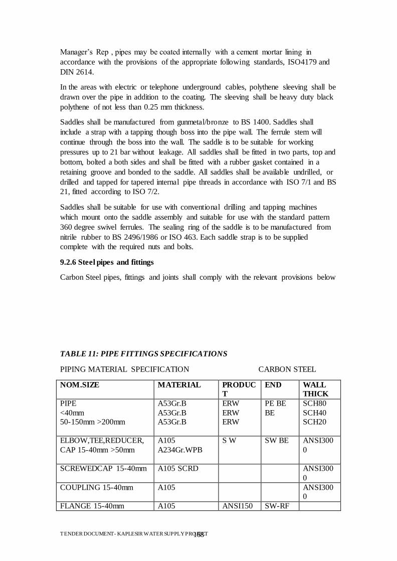
TENDER DOCUMENT- KAPLESIR WATER SUPPLY PROJECT 168
Manager‟s Rep , pipes may be coated internally with a cement mortar lining in
accordance with the provisions of the appropriate following standards, ISO4179 and
DIN 2614.
In the areas with electric or telephone underground cables, polythene sleeving shall be
drawn over the pipe in addition to the coating. The sleeving shall be heavy duty black
polythene of not less than 0.25 mm thickness.
Saddles shall be manufactured from gunmetal/bronze to BS 1400. Saddles shall
include a strap with a tapping though boss into the pipe wall. The ferrule stem will
continue through the boss into the wall. The saddle is to be suitable for working
pressures up to 21 bar without leakage. All saddles shall be fitted in two parts, top and
bottom, bolted a both sides and shall be fitted with a rubber gasket contained in a
retaining groove and bonded to the saddle. All saddles shall be available undrilled, or
drilled and tapped for tapered internal pipe threads in accordance with ISO 7/1 and BS
21, fitted according to ISO 7/2.
Saddles shall be suitable for use with conventional drilling and tapping machines
which mount onto the saddle assembly and suitable for use with the standard pattern
360 degree swivel ferrules. The sealing ring of the saddle is to be manufactured from
nitrile rubber to BS 2496/1986 or ISO 463. Each saddle strap is to be supplied
complete with the required nuts and bolts.
9.2.6 Steel pipes and fittings
Carbon Steel pipes, fittings and joints shall comply with the relevant provisions below
TABLE 11: PIPE FITTINGS SPECIFICATIONS
PIPING MATERIAL SPECIFICATION CARBON STEEL
NOM.SIZE MATERIAL PRODUC
T
END WALL
THICK
PIPE
<40mm 50-150mm >200mm
A53Gr.B
A53Gr.B A53Gr.B
ERW
ERW ERW
PE BE
BE
SCH80
SCH40 SCH20
ELBOW,TEE,REDUCER,
CAP 15-40mm >50mm
A105
A234Gr.WPB
S W SW BE
ANSI300
0
SCREWEDCAP 15-40mm A105 SCRD ANSI300
0
COUPLING 15-40mm A105 ANSI3000
FLANGE 15-40mm A105 ANSI150 SW-RF
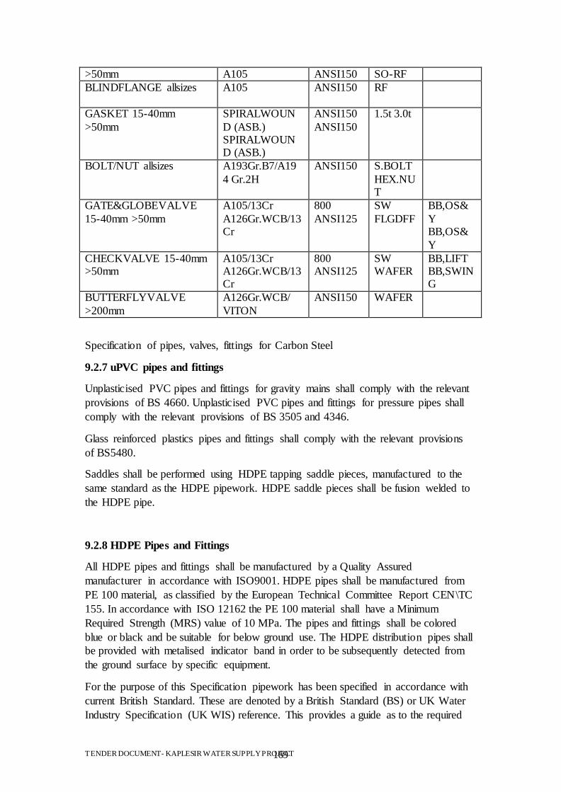
TENDER DOCUMENT- KAPLESIR WATER SUPPLY PROJECT 169
>50mm A105 ANSI150 SO-RF
BLINDFLANGE allsizes A105
ANSI150 RF
GASKET 15-40mm
>50mm
SPIRALWOUN
D (ASB.) SPIRALWOUND (ASB.)
ANSI150
ANSI150
1.5t 3.0t
BOLT/NUT allsizes A193Gr.B7/A19
4 Gr.2H
ANSI150 S.BOLT
HEX.NUT
GATE&GLOBEVALVE
15-40mm >50mm
A105/13Cr
A126Gr.WCB/13Cr
800
ANSI125
SW
FLGDFF
BB,OS&
Y BB,OS&
Y
CHECKVALVE 15-40mm >50mm
A105/13Cr A126Gr.WCB/13Cr
800 ANSI125
SW WAFER
BB,LIFT BB,SWING
BUTTERFLYVALVE
>200mm
A126Gr.WCB/
VITON
ANSI150 WAFER
Specification of pipes, valves, fittings for Carbon Steel
9.2.7 uPVC pipes and fittings
Unplasticised PVC pipes and fittings for gravity mains shall comply with the relevant
provisions of BS 4660. Unplasticised PVC pipes and fittings for pressure pipes shall
comply with the relevant provisions of BS 3505 and 4346.
Glass reinforced plastics pipes and fittings shall comply with the relevant provisions
of BS5480.
Saddles shall be performed using HDPE tapping saddle pieces, manufactured to the
same standard as the HDPE pipework. HDPE saddle pieces shall be fusion welded to
the HDPE pipe.
9.2.8 HDPE Pipes and Fittings
All HDPE pipes and fittings shall be manufactured by a Quality Assured
manufacturer in accordance with ISO9001. HDPE pipes shall be manufactured from
PE 100 material, as classified by the European Technical Committee Report CEN\TC
155. In accordance with ISO 12162 the PE 100 material shall have a Minimum
Required Strength (MRS) value of 10 MPa. The pipes and fittings shall be colored
blue or black and be suitable for below ground use. The HDPE distribution pipes shall
be provided with metalised indicator band in order to be subsequently detected from
the ground surface by specific equipment.
For the purpose of this Specification pipework has been specified in accordance with
current British Standard. These are denoted by a British Standard (BS) or UK Water
Industry Specification (UK WIS) reference. This provides a guide as to the required
TENDER DOCUMENT- KAPLESIR WATER SUPPLY PROJECT 170
standard and the Contractor may use any other recognized international standards,
which are applicable to HDPE pipework.
All HDPE pipes shall comply with the provisions of UK WIS 4-32-03. Joints and
fittings shall comply with the provisions of UK WIS 4-32-15, UK WIS 4-32-11, UK
WIS 4-32-14, UK WIS 4-24-01 and UK WIS 4-32-08, depending on the type of joints
and fittings used.
Generally, all buried pipes shall be jointed using either butt or electrofusion welding
techniques. Small diameter pipes (D<63 mm), pipes within structures and pipes
connecting to metal fittings shall be jointed using mechanical jointing techniques,
such compression, flanged joints or push-fit joints.
9.2.9 GRP pipes and fittings
Glass reinforced plastics (GRP) pipes and fittings shall comply with the relevant
provisions of BS 5480.
All pipes and fittings shall have the minimum initial specific stiffness and be classed
as pressure pipe with a pressure classification as given in the Contract. Allowable pipe
deflections shall be as follows:
TABLE 12: GLASS REINFORCED PIPES
Pressure pipes Gravity pipes
Long term permissible deflection – 6%
Long term permissible deflection – 6%
Initial deflection – design – 3 % Initial deflection – design – 0.5 to 4 %
Initial defelction – installed - 5 % Initial deflection – installed - 1 to 5 %
Note that the lower limits will apply in weaker soils
Every individual pipe's wall thickness shall be measured and recorded. Where the
pipe's wall is less than the designed minimum, it shall be rejected unless it can be
shown to meet the minimum stiffness value.
Pipes shall be joined by means of a push fit sleeve coupling comprising an EPDM
rubber seal bonded inside a GRP casing. The rubber seal shall extend over the full
length of the joint and shall have moulded central register with two pressure-actuated
lip seals either side.
Pipes shall be plain ended, shall have a smooth outer surface and shall have a constant
outside diameter throughout their length thus allowing them to be cut and jointed at
any position along their length without the need for any special preparation of the cut
end, other than resealing the exposed fibres.
Handling, storage and installation shall be carried out strictly in accordance with the
manufacturer's recommendations. The Contractor's pipe laying labour will be
required to demonstrate that they have attended the pipe manufacturer's own
training course for the installation of GRP pipes and fittings, before they are permitted
to commence pipe laying activities.
TENDER DOCUMENT- KAPLESIR WATER SUPPLY PROJECT 171
Where bends are fabricated in GRP they shall be to the same standard as the pipes.
Longitudinal angular deflections at the joints shall not exceed the maximum stated by
the manufacturer.
Fittings including flange joints, bends, tee pieces, tapped pieces and junctions shall be
standard GRP fittings and shall comply with BS 5480.
9.2.10 Ferrules
The ferrules shall be a main stem complete with a 360 degree swivel outlet at 90
degrees suitable for push fit connection to HDPE pipe with control of water flow via a
threaded inner plug. The inlet thread shall be a male taper thread to BS 21/1975 or
ISO 7/1.
The ferrules shall be for use underground and handling of potable water at
temperatures up to 35 degrees Celsius and capable of working at 21 bar without
leakage. The ferrules shall either be self-tapping or shall permit service pipe
installation via conventional drilling and tapping machines dry, or under pressure with
saddles. The ferrules shall further permit use with conventional drilling machines
which mount onto the ferrule/saddle assembly and drill the main via the ferrule stem
water way, dry or under pressure.
The ferrule stem, banjo, inner plug and top cap shall be manufactured of
gunmetal/bronze to BS l400/l986LG2. The banjo washers and top cap washer shall be
manufactured in nitrile rubber to BS 2494 and shall provide the sealing between the
outer body and the ferrule stem.
The ingress of dirt shall be prevented by a polyethylene top plug.
9.2.11 Push fit joints
In order to make up for mounting distances and not to force the pipes or fittings, push
fit joints shall be mounted.
All push fit joints and adapters shall meet the specification of ISO 3458, ISO 3459,
ISO 350l, ISO 3503/1976, BS 864/ l 978 part 3, BS 5ll4/ 1975, BS 8010/ l987.
All materials, grip ring for end resistance, O ring for watertight seal and live, from
metal or rubber shall be in accordance with ISO 9001 or EN 2900 1.
9.3 Transportation of pipes and fittings
Any vehicle on which pipes are to be transported shall have a body of such length that
the pipes do not overhang. The pipes shall be handled in accordance with the
manufacturer‟s recommendations. Approved slings shall be used and all hooks and
dogs and other metal devices shall be padded. Hooks engaged on the inner wall
surface at pipe ends shall not be used. Pipe handling equipment shall be maintained in
good repair and any equipment which in the opinion of the Project Manager‟s Rep
may cause damage to the pipes shall be discarded.
Under no circumstances shall pipes be dropped, be allowed to strike one another, be
rolled freely, or dragged along the ground.
TENDER DOCUMENT- KAPLESIR WATER SUPPLY PROJECT 172
9.4 Storage of pipeline materials
All pipes shall be stored in accordance with the manufacturer‟s recommendations, in
order to preserve their quality and condition to the standards set out in the
Specification. Particular care shall be taken in respect to HDPE and GRP pipes.
Pipes and fittings shall be stored raised from the ground and shall be carefully
supported, cushioned and wedged. Pipes shall not rest directly on one another and
shall not be stacked more than four pipes high, or two pipes high in the case of pipes
greater than DN 500. Couplings and joints (and all components thereof) and other
similar items shall be stored in dry conditions, raised from the ground in sheds or
covered areas.
Storage areas shall be carefully set out to facilitate unloading, loading and checking of
materials with different consignments stacked or stored separately with identifications
marks clearly visible.
9.5 Inspections of pipes and fittings
Before incorporation into the pipeline each pipe shall be brushed out and carefully
examined for soundness. Damaged pipes, which in the opinion of the Project
Manager‟s Rep cannot be satisfactorily repaired, shall be rejected and removed from
the Site. If the Project Manager‟s Rep considers that an unacceptable proportion of the
pipes within a test length has failed, the Contractor may be required to test
hydraulically, to the site test pressure each pipe and joint before pipe laying. In this
event, test results shall be submitted to and approved by the Project Manager‟s Rep
before any further pipes are laid. The cost of individual pipe testing shall be borne by
the Contractor.
9.6 Survey of pipeline routes
9.6.1 General
Prior to the commencement of excavation for any particular pipeline the Contractor
shall set out and survey the route of the pipeline as shown on the Drawings, or as
agreed with the Project Manager‟s Rep . The length of the route shall be accurately
measured and ground levels taken where required by the Project Manager‟s Rep. The
route of the pipeline shall be clearly marked on the ground.
9.6.2 Underground services
Having identified the proposed pipeline route, the Contractor shall liaise with the
utility companies before commencing any excavation. With the assistance of the
utility companies the Contract shall satisfy himself as to the exact location of all
existing-underground services which may affect or be affected by the excavation of
the pipeline. This may require the use of an electromagnetic pipe locator and test pits
as described in b) above.
Having determined the exact location of any underground services, the Contractor
shall prepare a details and issue them to the Project Manager‟s Rep.
9.6.3 Survey results
TENDER DOCUMENT- KAPLESIR WATER SUPPLY PROJECT 173
The results of the survey, comprising ground levels, connection point invert
levels, diameters and underground service details shall be submitted to the Project
Manager‟s Rep . The Contractor shall prepare details of the following for the
pipeline,
underground services.
At all times the pipeline surveying shall be sufficiently ahead of the excavation and
pipe laying to permit agreement to be reached between the Project Manager‟s Rep and
the Contractor on the lines, levels and gradients of the pipeline.
Notwithstanding the requirement for an 'excavation permit', the Contractor shall
not commence any excavation until confirmation of the above has been provided by
the Project Manager‟s Rep .
9.7 Pipelines under roads, footpaths and River crossings
The Contractor shall program the works to reduce the disruption to road traffic to a
minimum, and before work commences in the existing roads and footpaths shall
Obtain the full permission of Town Halls and relevant utility companies; Submit
details of his proposals, and obtain approval from the Project Manager‟s Rep.
Pipelines shall run along and cross roads and footpaths, where shown on the Drawings
and approved following the pipeline surveys. The roadway and footpath shall be
reinstated in accordance with the Specification.
All the pipes crossing roads, footpaths and rivers shall be Galvanized Iron pipes
conforming to the standards provided in the Pipe Material Section.
9.8 Installation
9.8.1 General
Installation of pipelines includes the excavation of trenches, supply, laying and
jointing of pipes and fittings, construction of beddings and foundations, manholes and
other structures in the line, testing, backfilling of trenches, disinfecting and
commissioning.
Pipes shall be laid in accordance with BS 8010.
All plant, operation and haulage required from source of supply or store to bring the
pipes, valves, etc., to their place of laying of fixing, including any unloading into
temporary storage areas and any subsequent reloading for haulage to the place of
laying shall be included in the supply of pipes and fittings.
During installation pipes are to be suitable anchored to prevent flotation prior to
backfilling. The Contractor shall submit to the Project Manager‟s Rep for his approval
his proposed method for control of the pipe laying to the correct levels and alignment.
Plastic pipes shall be marked with metallized indicator bends or plastic material
braiding provided with metallic wire insertion. The width of the metallized indicator
TENDER DOCUMENT- KAPLESIR WATER SUPPLY PROJECT 174
bends or plastic material braiding will be of 100 -150 mm and will be blue or black.
The wire for insertion will be made by stainless steel, if the plastic material braiding is
used. Also, the material will have humidity resistance and will be resistant to
underground location. They will be inductively and conductively detectable.
9.8.2 Excavation for pipes in trenches
Whether trenches for pipe lines are constructed with vertical, sloping, or stepped
sides, that portion of the trench which extends from the formation level to not less
than 300 mm above the crown of the pipe when laid in its correct position, shall,
unless otherwise specified, or ordered by the Project Manager‟s Rep , be formed with
vertical sides the minimum practical distance apart and shall be such that the distance
between the sides of the trench and the barrel of the pipe does not exceed the
following, inclusive of any allowances for temporary trench supports :
width - pipe outside diameter + 0.4 m
total width of cables and spacing + 0.2 m
absolute minimum 0.6 m
depth- pipe or cable outside diameter + 1.65 m
(0.15 under and 1.5 m cover on top of service)
No excavations with battered sides shall be made in roads, footpaths, private gardens,
or within l0 m of any existing or proposed building or other structure.
Excavation of the trenches for pipelines shall always be at least 15 m ahead of pipe
laying. Unless otherwise specified, this shall include excavation in the vicinity of
junctions where at least l5 m in each direction shall be excavated before the junction
fittings are installed. Should an obstacle be encountered during the excavation, then
the Project Manager‟s Rep shall be informed and the necessary action agreed prior to
laying more pipes on that section of the works. Should the Contractor have failed to
excavate ahead of pipe laying, then the cost of lifting and relaying the laid pipes be
met by the Contractor.
The material excavated from the trenches shall be handled with care, with asphalt,
stone blocks, rock and stone from road construction or broken out of the trench during
excavation, stock piled separately from the granular material of the natural ground.
9.8.3 Foundation and bedding
Unless specified otherwise, pipelines shall be laid in trenches excavated in the ground
conforming to Clause "Excavation ". Unless unsuitable soil is encountered, trenches
shall be excavated to 250 mm below the barrel of the pipe and prepared conforming to
Clause "Preparation of Foundation”.
On the trench bottom a sand bedding shall be laid to a compacted thickness of 250
mm. The bedding sand shall comply with BS 882 grading zone C for Fine Aggregate
and an aggregate impact value not exceeding 45%. Pipe bedding to concrete pipes
shall contain no more than 0.3% sulphate. The bedding shall be compacted to 95 % of
the standard maximum dry density. The level tolerance for the bedding shall be 10
mm.
TENDER DOCUMENT- KAPLESIR WATER SUPPLY PROJECT 175
In case a pipe of over 400 mm is to be used, the bedding shall be 5 % of the diameter
thicker than 250 mm. The additional layer shall be shaped concentrically with the pipe
along the bedding angle. Where pipes are jointed, bell holes of ample dimensions
shall be formed in the bedding to ensure that each pipe is uniformly supported
throughout the length of its barrel and to enable the joint to be made. Pipes shall
be laid on sufficient setting blocks only where a concrete bed or cradle is used. Pipe
bedding shall be constructed as shown on the Drawings.
The classes of bedding to be used are indicated below:
Class of bedding Brief description of bedding material
A Mass Concrete
A2 Reinforced Concrete
B Granular material
S Granular material (bed and surround)
The granular material shall be spread over the full width of the formation and lightly
hand compacted to a level slightly higher than the level corresponding to the
underside of the pipe barrel to allow for settlement of the pipe to the correct level.
Further granular material shall be placed in the trench, special care being taken to fill
under the sides of the pipe to ensure full contact with the barrel of the pipe, but
leaving the joint exposed for a length of approximately 200 mm on each side of the
joint collar, sleeve or socket. The granular material shall then be compacted evenly on
both sides of the pipe.
Clay, or other approved impermeable material barriers shall be constructed to limit
the uninterrupted length of granular bedding and backfill to a maximum of 500 m.
The cost of this provision shall be deemed to be included.
9.8.4 Jointing and cutting
All joints shall comply with the relevant provisions of the appropriate International
standard and shall be made to the manufacturer's recommendations and the
Specifications hereafter.
Flanged joints shall be properly aligned before any bolts are tightened. Gaskets for
flanged joints shall be of the inside-bolt-circle type. Jointing compounds shall not be
used when making flanged joints, except that to facilitate the making of vertical
joints, gaskets may be secured temporarily to one flange face by a minimum quantity
of clear rubber solution. Bolt threads shall be treated with graphite paste and the nuts
shall be tightened evenly in diametrically opposite pairs. Nuts shall be secured against
loosening by vibration.
Rubber joint rings for water mains and drainage purposes shall be Types 1 and 2
respectively, complying with the relevant provisions of BS 2494 and shall be
obtained from the pipe manufacturer. Joint lubricants for sliding joints and used for
TENDER DOCUMENT- KAPLESIR WATER SUPPLY PROJECT 176
jointing water mains shall not impart to water taste, color, or any effect known to be
injurious to health, and shall be resistant to bacterial growth.
Unless specified otherwise joints having exposed mild steel components shall be
cleaned and all loose rust shall be removed. The internal lining in a gap which has
been left for the joint to be made shall be completed in accordance with the
recommendations issued by British Steel Corporation or other
approved supplier, unless specified otherwise. The external protection shall comprise
bitumen applied to a thickness of not less than one millimeter on to the external
surface of the joint, followed where appropriate by a spiral wrap of heavy duty glass
fiber tape bonded with hot bitumen.
For closing lengths, it may be necessary to cut pipes of various materials. Pipes shall
be cut by a method which provides a clean square profile without splitting or
fracturing the pipe wall, and which causes minimum damage to any protective
coating. Where necessary, the cut ends of pipes shall be formed to the tapers and
chamfers suitable for the type of joint to be used and any protective coatings shall be
made good.
Where ductile pipes larger than 450 mm diameter are to be cut to form a non-standard
lengths, the Contractor shall comply with the manufacturer's recommendations in
respect of ovality correction to the cut spigot end.
Where cut concrete pipes are used any exposes reinforcement shall be sealed with an
approved epoxy resin.
9.8.5 Curves and bends
The pipes shall be laid in straight lines where possible. Curves of long radius shall be
obtained by deflection at the joints. The deflection of the joints for this purpose shall
not be more than 50 % of the maximum deflection as specified by the pipe
manufacturer for the relevant type of joint. Where a required change of direction
cannot be obtained by deflection of the joints, prefabricated bends shall be used.
Concrete thrust blocks shall be provided to pressure pipelines at reducers, tee
junctions, caps, etc. and curves or bends deflecting 11.25° or more, where ordered by
the Project Manager‟s Rep or indicated on the Drawings, except where welded steel
pipes or self-anchoring joints are used. The type and size of thrust blocks shall be in
accordance with the Drawings or as approved by the Project Manager‟s Rep.
Concrete for thrust blocks shall comply with all the relevant requirements of Clause
"Concrete Work" and shall be placed carefully against undisturbed earth or rock with
suitable bearing capacity and shall in no case be less than 150 mm of cover to the
pipe. Concrete shall be grade Bc 7.5. When casting thrust blocks, no couplings or
joints shall be covered, and if required the pipe with fittings shall be firmly fixed to
the block by a suitable stainless steel strap bolted to the block. Where timber
shuttering has been used such timber shall be removed before backfilling. The
concrete shall be allowed to develop adequate strength prior to any pressure being
applied to the pipeline.
TENDER DOCUMENT- KAPLESIR WATER SUPPLY PROJECT 177
9.8.6 Protection and backfill
After excavation of the trench, placing and compacting the bedding, laying the pipe
and concreting the thrust blocks the pipe must be surrounded by fill or concrete.
Unless otherwise specified, the space between the sides of the trench and the pipe
must be backfilled with the same material as for the bedding. It shall be placed and
compacted conform the requirements of Clause "Placing and Compaction of Fill and
Backfill". Special care must be taken to backfill on both sides of the pipe evenly to
support
the pipe properly and avoid distortion of the pipe. Unless specified otherwise the pipe
surround is continued up to a level 200 mm above the pipe crown. The layers shall be
compacted, in layers not exceeding l00 mm thick after compacting, by hand
controlled vibration on each side of the pipe only and not over the top of the pipe. Site
tests shall be made to prove the effectiveness of the method of compacting at intervals
instructed by the Project Manager‟s Rep.
Unless otherwise specified the surround for concrete pipes shall be covered with clay
or concrete tiles of at least 40 mm thickness and compression strength of 5 N/mm².
The trench above the so finished pipe surround shall be filled with fill complying with
the requirements of Clause “Earthworks” and shall be compacted flush with ground
level according to the requirements of the Clause “Backfill and Fill ". Trench supports
shall be gradually withdrawn in accordance with the progress of the fill, subject at all
times to the provision that such withdrawal will not prejudice the safety of all works.
9.8.7 Concrete bed and surround
Where indicated on the Drawings, ordered by the Project Manager‟s Rep and where
pipes are surfacing or having less than the required ground cover of 600 mm, pipes
shall be surrounded by concrete grade C25. The pipes shall be supported on regularly
spaced blocks in accordance with any recommendations from the manufacturer.
Plastic pipes to receive concrete bed and surround shall be closely wrapped in a sheet
of plastic (nominal thickness 120 µm).
For pipes with flexible joints a compressible filler shall be cut and placed at each pipe
joint over the entire cross section of the concrete
Concrete shall be poured in a single operation and shall comply with the requirements
of Clause "Concrete Works".
9.9 Manholes and chambers
All chambers for valves, mixers, flow meters and the like shall be constructed from
reinforced concrete as indicated on the Drawings. Rectangular precast units shall be
interlocking and comply with the requirements of BS 5911: Part 2.
TENDER DOCUMENT- KAPLESIR WATER SUPPLY PROJECT 178
All manholes shall be constructed from reinforced concrete except brickwork may be
used where indicated on the Drawings. Unless otherwise indicated they shall be
provided with a reinforced concrete cover slab and with a ductile iron cover and frame
in a square rectangular or circular opening or as specified on the drawings. The clear
opening shall be a minimum of 600mm diameter or square and the edges of the
opening are to be chamfered. Covers are to be suitable for the anticipated loading and
are to comply with the provisions of BS EN 124. They shall be set in mortar, not
weigh more than 100 kg and be provided with handles or suitable lifting eyes. Covers
are to be free from surface imperfections or blemishes.
All concrete shall be grade BC 25 as Clause "Concrete mixes" and shall meet the
requirements of Clause "Concrete work". The concrete shall be watertight and have a
thickness of not less than 200 mm and
incorporate water stops. Where indicated on the Drawings, drainage into a granular
filter shall be provided to the manhole.
Brickwork shall comply with the relevant provisions of BS 5628, part 3.
Rung irons or step irons are to be provided where indicated. They shall comply with
the relevant provisions of BS 1247. Their size and strength shall be suitable for access
to the manhole with a maximum vertical spacing between steps of 350mm in a
vertical alignment.
Pipes passing through the concrete walls of a manhole shall be provided with ductile
iron or steel spool pieces with puddle flanges. Alternative means of preventing the
passage of water are subject to the approval of the Project Manager‟s Rep. A flexible
joint shall be situated as close as practicable to the outside face of any manhole or
other structure.
Manhole inverts and benchings in drains and culverts shall be formed in concrete
grade C25 to the same gradient and diameter as the connected pipework and with a
smooth finish.
9.10 Pipe work connections
Breaking out of existing chamber walls and/or bases for the connection of new
pipelines shall be undertaken with all due care and attention, to minimize damage to
the structure of the existing chamber. After introduction of the new pipe the remainder
of the opening shall be sealed and made good with epoxy based mortar or other
suitable material as approved by the Project Manager‟s Rep.
For connections to existing reinforced concrete wall or bases, the existing reinforcing
bars shall be cropped cleanly and new reinforcement introduced around the opening.
For connections to existing concrete sewer pipes saddles shall be used, bedded on
mortar. Where a saddle is not available for the particular location a pipe may be cut to
the required angle so as not to protrude into the pipe. The cut pipe is to be bedded
firmly in mortar externally and, where possible, internally.
9.11 Interference with Structures
TENDER DOCUMENT- KAPLESIR WATER SUPPLY PROJECT 179
Pipes shall be laid as far as possible clear from any structures. For pipes built into
structures, the same requirements as for pipes passing through manholes apply.
9.11.1 General
As soon as pipes have been placed on their bedding and before backfilling they shall
be tested for leakage. Before any testing, the Contractor shall ensure that the pipeline
is anchored adequately and that thrusts from bends, branch outlets or from the
pipeline ends are transmitted to solid ground or to a suitable temporary anchorage.
Open ends shall be stopped with plugs, caps or blank flanges properly jointed.
Testing shall be done under supervision of the Project Manager‟s Rep. The Contractor
shall notify the Project Manager‟s Rep at least one clear working day beforehand of
his intention to test a section of pipeline.
9.11.2 Testing of pressure pipelines
Gauges for testing pressure pipelines shall either be of the conventional circular type,
not less than 300 mm in diameter, calibrated in meters head of water, or shall have a
digital indicator capable of reading increments of0.1 m head. They shall be graduated
such that the test pressure is at least 75% of the reading. Before any gauge is used the
Contractor shall arrange for it to be checked independently, and a dated certificate of
its accuracy shall be provided. Two gauges of each type to be used shall be provided
for the sole use of the Project Manager‟s Rep and shall remain in the Project
Manager‟s Rep‟s possession for the duration of the contract.
Before testing, valves shall be checked and sealed, the sections of main filled with
water and the air released. After having been filled, pipelines shall be left under
operating pressure for the period of not less than 3 hours, so as to achieve conditions
as stable as possible for testing.
The pressure shall then be raised slowly in 3 steps (0.5Pn, Pn, 1.5Pn) every fifteen
minutes until the test pressure being 150 % times the working pressure is reached in
the lowest part of the tested section, and the pressure shall be maintained at this level,
for a period of one hour.
The pipe section shall be considered as having passed the test if leakage is less than
0.02 litres/mm of pipe diameter per kilometer per 24 hours for each l bar of pressure
applied when measured over a period of steady pressure of not less than 4 hours. The
period of sustained pressure shall be extended in accordance with the Project
Manager‟s Rep‟s instructions. Where high daily variations in ambient temperature
prevail the Project Manager‟s Rep may require that 24 hour test periods are
mandatory. In case of failure of the test the fault will be repaired and the test will be
repeated completely at the Contractor‟s expense.
Notwithstanding the satisfactory completion of the hydraulic test, if there is any
discernible leakage of water from any pipe or joint the Contractor shall at his own
cost, replace the pipe, repair the pipe or remake the joint and repeat the hydraulic test.
In addition to the tests on separate sections, the whole pipeline shall be tested on
completion to the same procedure as that outlined for individual sections.
TENDER DOCUMENT- KAPLESIR WATER SUPPLY PROJECT 180
9.11.3 Testing of Gravity Pipelines
For the purpose of this clause "gravity pipelines" are defined as pipelines which are
not completely filled with water such a certain sewers and culverts in open drains.
Testing Gravity pipelines laid in open cut shall be tested after they are jointed but
before any concreting or backfilling is commenced, other than such may be necessary
for the structural stability whilst under test. A further test shall be carried out after the
backfilling is complete.
The pipelines shall be tested by means of a water test and by visual inspection, in
lengths determined by the course of construction, in accordance with a program
approved by the Project Manager‟s Rep.
The test pressure for gravity pipelines shall be not less than 1.2 metres head of water
above the pipe soffit at the highest point and not greater than 6 metres above the
lowest point of the section.
The pipeline shall be filled with water and a minimum period of two hours shall be
allowed for absorption, after which water shall be added from a measuring vessel at
intervals of 10 minutes and the quantity required to maintain the original water level
noted. Unless otherwise specified the length of pipeline shall be accepted if the
quantity of water added over a 30 minute period is less than 0.5 litre per lineal metre
per metre of bore. The contractor is responsible for the supply and disposal of water
from the test, and any subsequent re-test, in a safe and acceptable manner.
Notwithstanding the satisfactory completion of the above test, if there is any
discernible leakage of water from any pipe or joint, the pipe shall be replaced and or
the joint shall be re-made, as appropriate, and the test repeated until the leakage is
stopped.
Gravity pipelines and manholes shall be tested for infiltration after backfilling and
removal of any temporary drainage. All inlets to the system shall be effectively
closed, and any residual flow shall be deemed to be infiltration.
The pipeline, including manholes, shall be accepted as satisfactory if the infiltration in
30 minutes does not exceed 0.5 litres per lineal metre per metre of bore.
9.12 Tolerances
Pipes shall be laid accurately to the lines and levels shown on the Drawings. The
maximum permitted deviation from the specified line and level for pipelines shall be
for the following diameters,
up to 600mm 10mm
greater than600mm 15mm
9.13 Disinfection
On completion of the hydraulic test on water mains, a foam swab shall be passed
through the main for final cleansing sufficient times to achieve clear wash water.
TENDER DOCUMENT- KAPLESIR WATER SUPPLY PROJECT 181
The mains and tanks shall then be filled with a chlorine solution of a strength of 30
mg/l. The chlorine solution shall remain in the system for 24 hours or for such longer
period as the Project Manager‟s Rep shall require and all valves in the system shall be
operated at least once during this period. After which the system shall be flushed till
the outflowing water at all points has a chlorine content equal to that produced by the
treatment plant.
After 24 hours samples of water in the system shall be taken and tested by an
approved laboratory for compliance with the requirements of the appropriate utility
companies or organizations if the results of such tests are not satisfactory sterilization
shall be repeated until satisfactory results are obtained.
The Contractor shall obtain the Project Manager‟s Rep‟s approval of the method to be
adopted for disposing of the chlorinated water and the time when such disposal shall
take place on completion of the disinfection.
9.14 Reinforced concrete tanks
Reinforced concrete tanks shall be constructed as indicated in the Drawings. All
clauses in the Specifications for "Concrete Works" shall apply. The concrete shall be
watertight. All joints shall thus be provided with suitable waterstops. Upon
completion the tank shall be tested for water tightness and comply with requirements
of clause "Concrete Works - Testing of Concrete Water Retaining Structures".
9.15 Design details for steel pipes
9.15.1 Material specification changes
When a line is connected to another line of different material specification or pressure
rating, a valve or flanges connecting these two lines shall be constructed with the
higher material specification or pressure rating between the two, unless otherwise
indicated on the applicable drawings.
9.15.2 Bends, mitres and elbows
Elbows shall be used to change the direction of piping, however bends and mitres
may be used instead. The radius of bends shall be from 4-6 times the nominal outside
diameter.
Pipes indicated below may be cold bent at site: Carbon steel piping: < 40 mm;
Stainless steel piping: < 40 mm.
Long radius elbows shall be used for piping larger than 50 mm, unless specified
otherwise.
9.15.3 Reducers
Reduction in line size shall be made by screwed, butt welded or socket weld fittings.
9.15.4 Branch connections
Branch connections shall generally be made by screw tees, socket or butt welding
tees, half couplings, welding outlet fittings or welded pipe-to pipe connections. When
TENDER DOCUMENT- KAPLESIR WATER SUPPLY PROJECT 182
welded pipe-to-pipe connections are applied, unless the wall thickness of the pipe is
sufficient to sustain the pressure and thermal stress, it is necessary to provide
reinforcement. Welded pipe-to-pipe connections shall be designed so that the angle of
intersection between the branch and the run is not less than 45°.
9.15.5 Flanges
The use of flanges in piping shall be limited to connections at flanged equipment and
valves. Flanges shall also be used in special cases such as:
where frequent dismantling of piping is required.;
where plastics, non-metallic, cast-iron or lining piping cannot be welded or
otherwise joined except by flanges.
Steel flanges to be bolted to cast iron flanges of ANSI or PN code shall be as follows:
class ANSI-150 / PN-10 flat face steel flanges to class ANSI-125 /PN-6 cast
iron;
class ANSI-300 / PN-40 raised face steel flanges to class ANSI-250 /PN-16
cast iron flange.
9.15.6 End closures
Welding caps, blind flanges and screwed caps shall be used as end closure.
9.15.7 Flanges
Inside diameters of welding neck type flanges shall generally be equal to those of
connected pipes. Unless otherwise specified, welding and preparation of flange shall
conform to those of pipes.
9.15.8 Fittings
Wall thickness of butt welding type fittings shall be equal or greater than the nominal
wall thickness of connected pipe.
9.15.9 Bolt and nuts for line flanges
Dimension and surface finish shall be as follows:
Unified coarse screw threads, for U1-1/8 and over, 8 thread per inch; Stud bolts shall
be threaded in their total length; Bolt length shall be determined by the Contractor.
9.15.10 Welding end preparation
When two piping materials whose nominal wall thickness is different from each other
by more than 1.6 mm are butt-welded. The ends shall be trimmed.
9.15.11 Provisions for expansion and flexibility
Provision for expansion shall normally be made with Bellows type, Rubber expansion
joints or other expansion joints may be used where necessary. When expansion joints
are applied, adequate guides for piping shall be provided to avoid eccentricity of the
centre line.
TENDER DOCUMENT- KAPLESIR WATER SUPPLY PROJECT 183
All piping systems shall be designed so that the loads and moments at the flanges of
mechanical equipment such as pumps and compressors shall not exceed the
permissible reactions for this equipment as specified by the manufacturers of the
equipment.
9.15.12 Supports and hangers for above-ground piping
Pipes across valleys and river crossings shall have reinforced concrete support piers as
directed in the drawings or by the Project Manager‟s Rep. Concrete works for the
piers shall conform to the specifications in the Concrete Works Section. These
exposed pipes will be Galvanized Iron pipes of respective sizes.
All pipe sections which pass through walls of water retaining structures shall
incorporate integral puddle flanges for building in and shall be left uncoated
externally over the length encased in the concrete.
All piping shall be adequately supported by hangers or supports of proper structural
design. Support span shall be determined, considering the stress and strain caused by
the weight of the piping component, fluid and insulation.
Lines shall be provided with suitable supports to prevent excessive expansion forces
on equipment and excessive vibration.
Piping at valves and mechanical equipment, such as pumps, requiring periodical
maintenance shall be supported so that the valves and equipment can be removed with
a minimum necessity of installing temporary pipe supports.
Pipe support details shall be furnished for piping of 50 mm and over, piping subject to
high pressure or vibration, and other specific piping.
Pipe lines 200 mm and under shall be supported to carry their weight with water for
hydrostatic test. Pipe lines250 mm and over shall be supported to carry their weight
conforming to service fluid conditions.
9.15.13 Joints and connections
Pipe joints shall be as follows:
joints in piping systems shall preferably be butt-welded; connections to equipment
and vessels shall be flanged.
9.15.14 Pump Piping Installation
Suction lines to pumps shall generally be designed to avoid pockets.
The discharge line from centrifugal pumps shall be provided with a check valve
between the pump and the block valve. For vertical discharge pumps, the check valve
shall be located in the vertical line whenever practical.
Suction and discharge lines of pumps shall be drained through drains located at the
low point of the pump casing whenever possible.
TENDER DOCUMENT- KAPLESIR WATER SUPPLY PROJECT 184
Temporary strainers shall be provided at the largest flanges between the pump suction
nozzle and the first valve in the suction line. Permanent strainers should be as
indicated on the drawings.
9.15.15 Vents and Drains
Venting and draining shall be accomplished through vessel or equipment connections.
Vessel vents and drains may be located in overhead or bottom piping when valves or
blinds are not located in overhead or bottom piping when valves or blinds are not
located between vent or drain connections and vessels.
Pockets of piping shall be provided with 20 mm vents or drains.
9.15.16 Pressure Testing
On completion of erection, all pipe work shall be hydraulically tested to 1.5 times the
maximum working pressure. The test pressure shall be maintained for two hours in
the presence of the Project Manager‟s Rep and any leaks shall be rectified at the
Contractor's expense.
The Contractor shall supply all necessary equipment including pumps, blank flanges,
gauges, etc for these tests.
9.16 Steel piping material specifications
9.16.1 General
When the piping is connected to equipment, this specifications shall be used to the
extent given below: Companion flanges, gaskets, bolts and nuts for equipment
nozzles;
First block valve with companion flanges, gaskets, bolts and nuts for relief valves;
Companion flanges, gaskets, bolts and nuts at the matching point between the piping
furnished as a part of equipment by its manufacturer.
This specification shall not be used for special designed companion flanges, gaskets,
bolts and nuts at equipment nozzles.
9.16.2 Materials
Each component of all piping systems shall meet dimensional, material and other
requirement of standards for piping elements by BS, ASTM or DIN. Pipes and fittings
shall be coated internally and externally with hot applied bitumen coatings or
equivalent.
9.16.3 Carbon content
Carbon steel having a carbon content of more than 0.33 % shall not be used in
welding constructions or to be shaped by oxygen cutting or thermal cutting process.
TENDER DOCUMENT- KAPLESIR WATER SUPPLY PROJECT 185
9.16.4 Corrosion allowance
Corrosion allowance shall be 1.7 mm for carbon steel and low alloy steel pipes. No
corrosion allowance shall be taken for stainless steel pipes. Corrosion allowance shall
be 3.0 mm for cooling water, fire water and service water lines.
9.16.5 List of Abbreviations
ANSI American National Standard Institute
MSS Manufacturers Standardization Society of the Valve and Fitting
Industry
BB Bolted Bonnet
BE Bevelled End
BW Butt Weld
ERW Electric Resistance Weld
FF Flat Face
FLGD Flanged
GI Galvanized Iron
OS&Y Outside screw and Yoke type
PE Plain End
RF Raised Face
S Seamless
SCRD Screwed
SMLS Seamless
SCH Schedule
SW Socket Weld
SO Slip On
10 VALVES AND PENSTOCKS
10.1 General
All equipment and materials shall be of the highest quality from an approved
manufacturer whose products have proved reliable in service in similar installations.
The Contractor shall submit within his tender manufacture's literature describing the
equipment and materials he intends to provide.
Flanges on valves are to be fully faced drilled and rated in accordance with the
relevant Standards. Back faces shall be fully machined or spot faced for nuts and
washers. Flanged joints shall be provided to the relevant provisions of BS4504.
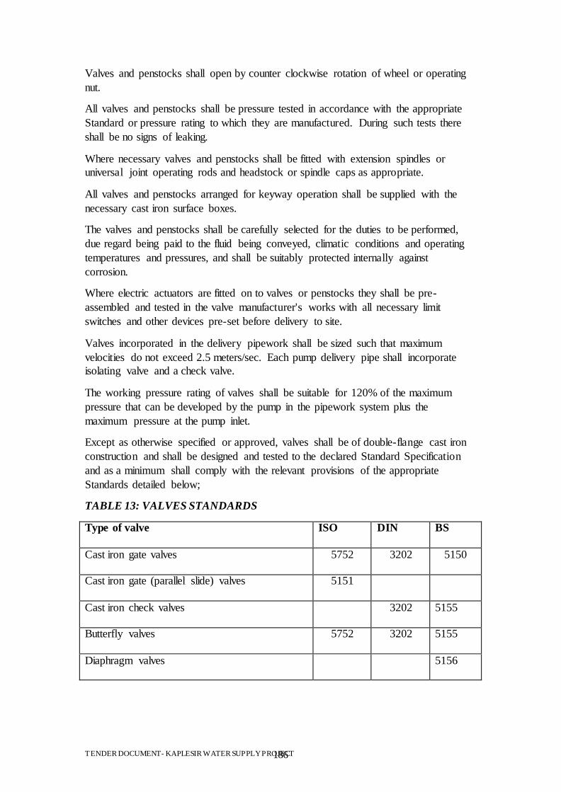
TENDER DOCUMENT- KAPLESIR WATER SUPPLY PROJECT 186
Valves and penstocks shall open by counter clockwise rotation of wheel or operating
nut.
All valves and penstocks shall be pressure tested in accordance with the appropriate
Standard or pressure rating to which they are manufactured. During such tests there
shall be no signs of leaking.
Where necessary valves and penstocks shall be fitted with extension spindles or
universal joint operating rods and headstock or spindle caps as appropriate.
All valves and penstocks arranged for keyway operation shall be supplied with the
necessary cast iron surface boxes.
The valves and penstocks shall be carefully selected for the duties to be performed,
due regard being paid to the fluid being conveyed, climatic conditions and operating
temperatures and pressures, and shall be suitably protected internally against
corrosion.
Where electric actuators are fitted on to valves or penstocks they shall be pre-
assembled and tested in the valve manufacturer's works with all necessary limit
switches and other devices pre-set before delivery to site.
Valves incorporated in the delivery pipework shall be sized such that maximum
velocities do not exceed 2.5 meters/sec. Each pump delivery pipe shall incorporate
isolating valve and a check valve.
The working pressure rating of valves shall be suitable for 120% of the maximum
pressure that can be developed by the pump in the pipework system plus the
maximum pressure at the pump inlet.
Except as otherwise specified or approved, valves shall be of double-flange cast iron
construction and shall be designed and tested to the declared Standard Specification
and as a minimum shall comply with the relevant provisions of the appropriate
Standards detailed below;
TABLE 13: VALVES STANDARDS
Type of valve ISO DIN BS
Cast iron gate valves 5752 3202 5150
Cast iron gate (parallel slide) valves
5151
Cast iron check valves 3202 5155
Butterfly valves 5752 3202 5155
Diaphragm valves 5156
TENDER DOCUMENT- KAPLESIR WATER SUPPLY PROJECT 187
All ductile iron sluice valves shall have bodies, spindle seal housing, bonnets and
gates of ductile iron (to BS2789); gates covered with nitrile rubber and have stainless
steel spindle (to BS 970), gunmetal spindle nuts, rubber wiper rings and double `O'
ring spindle seals contained in nylon housing bushes. The set screws and body/bonnet
bolts shall be fitted with `O' ring seals. The bodies shall have straight through bores
(without seating recess).
All ferrous parts are to receive the following protection system. All painting for shop
and site application to be obtained from the same manufacturer.
Shop Applied
Zinc spray to Zn4 of BS 2569: Part 1 to be applied immediately after shot blasting.
Surfaces are then to be etch primed and coated with high build coal tar epoxy to dry
film thickness of 150 microns.
Site Applied (After Erection)
High build coal tar epoxy to dry film thickness 150 microns to give total of 300
microns after all surfaces have been thoroughly cleaned and degreased and touched
up.
Non-ferrous materials may be used for valves and cocks of 40mm nominal bore and
below. Such valves may be flanged or internally threaded for screwed tube.
Each valve and penstock shall have cast-in lettering showing maker, year of
manufacture, nominal bore, rated working pressure and the Standard with which the
valve conforms, and where appropriate an arrow to indicate the direction of flow. In
addition each sluice and butterfly valve shall be provided with a complete set of
operating gear as set out below.
Valves and penstocks shall be installed on the suitable places to permit proper and
safe operation of the unit. Valves shall preferably not be installed with their stems
below horizontal.
Valves shall generally be gate valves. Globe valves shall be used when throttling is
required. Other kind of valves may be used where required or specified.
Valves having extended operating shafts shall be provided with all necessary
lubricated support brackets for the shaft extensions.
Gate, globe, lift and swing check valves for general use shall be in accordance with
table 5.5. Dimensions of other valves (butterfly, tilting check valve, ball valve, etc.)
shall be in accordance with
manufacturer's standard, but face to face dimension and end flange dimension shall
conform to those for same class valves in prescribed standards as much as possible.
The machine faces of flanges shall be coated with a suitable protective composition in
order to prevent their being affected by corrosion.
10.2 Valve installations
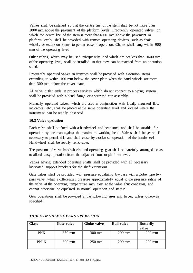
TENDER DOCUMENT- KAPLESIR WATER SUPPLY PROJECT 188
Valves shall be installed so that the centre line of the stem shall be not more than
1800 mm above the pavement of the platform levels. Frequently operated valves, on
which the centre line of the stem is more than1800 mm above the pavement or
platform levels, shall be provided with remote operating devices, such as chain
wheels, or extension stems to permit ease of operation. Chains shall hang within 900
mm of the operating level.
Other valves, which may be used infrequently, and which are not less than 3600 mm
of the operating level, shall be installed so that they can be reached from an operation
stand.
Frequently operated valves in trenches shall be provided with extension stems
extending to within 100 mm below the cover plate when the hand wheels are more
than 300 mm below the cover plate.
All valve outlet ends, in process services which do not connect to a piping system,
shall be provided with a blind flange or a screwed cap assembly.
Manually operated valves, which are used in conjunction with locally mounted flow
indicators, etc., shall be placed at the same operating level and located where the
instrument can be readily observed.
10.3 Valve operation
Each valve shall be fitted with a handwheel and headstock and shall be suitable for
operation by one man against the maximum working head. Valves shall be geared if
necessary to permit this and shall close by clockwise operation of the handwheel.
Handwheel shall be readily removable.
The position of valve handwheels and operating gear shall be carefully arranged so as
to afford easy operation from the adjacent floor or platform level.
Valves having extended operating shafts shall be provided with all necessary
lubricated support brackets for the shaft extensions.
Gate valves shall be provided with pressure equalizing by-pass with a globe type by-
pass valve, when a differential pressure approximately equal to the pressure rating of
the valve at the operating temperature may exist at the valve shut condition, and
cannot otherwise be equalized in normal operation and startup.
Gear operations shall be provided in the following sizes and larger, unless otherwise
specified:
TABLE 14: VALVE GEARS OPERATION
Class Gate valve Globe valve Ball valve Butterfly
valve
PN6 350 mm
300 mm
200 mm
200 mm
PN16 300 mm
250 mm
200 mm
200 mm
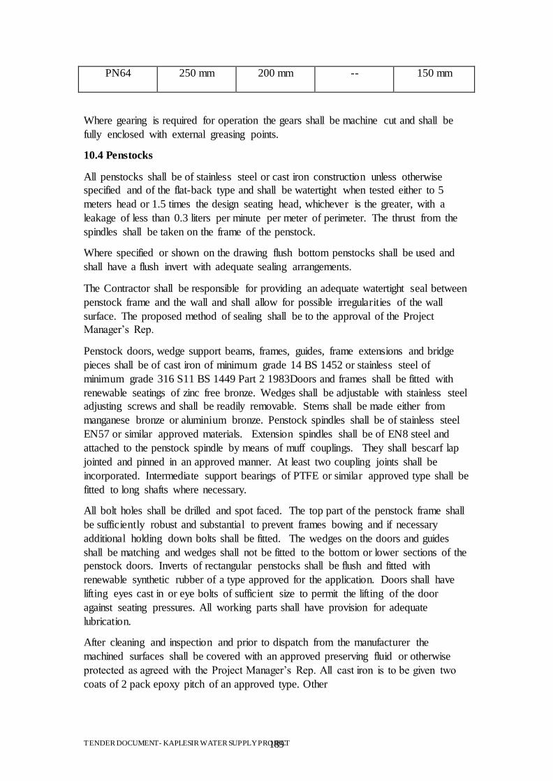
TENDER DOCUMENT- KAPLESIR WATER SUPPLY PROJECT 189
PN64 250 mm
200 mm
-- 150 mm
Where gearing is required for operation the gears shall be machine cut and shall be
fully enclosed with external greasing points.
10.4 Penstocks
All penstocks shall be of stainless steel or cast iron construction unless otherwise
specified and of the flat-back type and shall be watertight when tested either to 5
meters head or 1.5 times the design seating head, whichever is the greater, with a
leakage of less than 0.3 liters per minute per meter of perimeter. The thrust from the
spindles shall be taken on the frame of the penstock.
Where specified or shown on the drawing flush bottom penstocks shall be used and
shall have a flush invert with adequate sealing arrangements.
The Contractor shall be responsible for providing an adequate watertight seal between
penstock frame and the wall and shall allow for possible irregularities of the wall
surface. The proposed method of sealing shall be to the approval of the Project
Manager‟s Rep.
Penstock doors, wedge support beams, frames, guides, frame extensions and bridge
pieces shall be of cast iron of minimum grade 14 BS 1452 or stainless steel of
minimum grade 316 S11 BS 1449 Part 2 1983Doors and frames shall be fitted with
renewable seatings of zinc free bronze. Wedges shall be adjustable with stainless steel
adjusting screws and shall be readily removable. Stems shall be made either from
manganese bronze or aluminium bronze. Penstock spindles shall be of stainless steel
EN57 or similar approved materials. Extension spindles shall be of EN8 steel and
attached to the penstock spindle by means of muff couplings. They shall bescarf lap
jointed and pinned in an approved manner. At least two coupling joints shall be
incorporated. Intermediate support bearings of PTFE or similar approved type shall be
fitted to long shafts where necessary.
All bolt holes shall be drilled and spot faced. The top part of the penstock frame shall
be sufficiently robust and substantial to prevent frames bowing and if necessary
additional holding down bolts shall be fitted. The wedges on the doors and guides
shall be matching and wedges shall not be fitted to the bottom or lower sections of the
penstock doors. Inverts of rectangular penstocks shall be flush and fitted with
renewable synthetic rubber of a type approved for the application. Doors shall have
lifting eyes cast in or eye bolts of sufficient size to permit the lifting of the door
against seating pressures. All working parts shall have provision for adequate
lubrication.
After cleaning and inspection and prior to dispatch from the manufacturer the
machined surfaces shall be covered with an approved preserving fluid or otherwise
protected as agreed with the Project Manager‟s Rep. All cast iron is to be given two
coats of 2 pack epoxy pitch of an approved type. Other
TENDER DOCUMENT- KAPLESIR WATER SUPPLY PROJECT 190
steel shall be zinc or aluminium sprayed to a thickness of 0.15mm, one coat of
suitable primer applied at the works and two coats of 2 pack epoxy paint applied at
the site after renovation of primer as necessary. All external steel screw fixings for the
penstock shall be supplied in the galvanized condition, stainless steel or sheradised to
comply with BS 4921 Class 1 and Class2 with treatment.
The Contractor shall obtain details of the positioning of the holding down bolts and
locate any reinforcing bars in the walls away from the penstock fixing locations.
Dimension of spindle support brackets shall be determined by the Contractor and
submitted to the Project Manager‟s Rep for approval. Penstocks shall be installed in
accordance with the manufacturer‟s recommendations. The frame shall be secured in
position with approved resin anchor bolts complying with the relevant clause of the
Specification Clause or sheradised. Holes shall be drilled at the correct location and
to the recommended dimensions of the approved fixing bolt. Bolts shall be installed in
accordance with the manufacturer‟s recommendations.
Adequate support shall be provided to all headstocks. Where headstocks are not used,
the extension spindle shall be of sufficiently rigid construction and additional
supporting metalwork shall be provided, as necessary, to allow satisfactory operation
of the penstock.
Weir penstocks shall have a perfect level cill and shall be complete with top seals
unless otherwise stated.
10.5 Gate valves
Gate valves of 50mm to 600mm size shall comply with the latest Standards. Each
valve shall have cast or stamped on the outside of its body, the manufacturer's name,
its size and its pressure rating.
Each valve shall be fitted with a hand wheel not exceeding 450mm diameter and
headstock where specified and shall be suitable for operation by one man against the
maximum working head. Valves shall be geared if necessary to permit this and shall
close by clock-wise operation of the hand wheel. Hand wheels shall be readily
removable. Spindles shall be non-rising.
10.6 Butterfly valves
Butterfly valves shall comply with the latest Standards and shall be of the drop tight
closure, wafer type of the appropriate class with horizontal spindles. The valves shall
have cast iron body and disc and removable neoprene or nitrile rubber sealing faces.
Means of slinging shall be provided where necessary.
The operation of the valve shall be by hand and each valve shall be fitted with a
handwheel and headstock where specified, so arranged that (unless otherwise
specified) the valve will CLOSE by CLOCK-WISE operation of the hand wheel.
Valves shall be geared for one man operation and shall be fitted with indicators. Hand
wheels shall be readily removable.
10.7 Check valves
TENDER DOCUMENT- KAPLESIR WATER SUPPLY PROJECT 191
All check valves complying with the latest Standards shall be of the recoil type
designed to close rapidly without shock. The valves shall have a cast iron body to the
latest Standard, and renewable gunmetal seating faces to the latest Standards. The
valve covers shall be of ample size to allow clear access to the valve seats when the
valve is fully open and each valve shall be fitted with a bypass and isolating valve.
Each check valve shall have the direction of flow, nominal pressure rating and size
cast or stamped onto the body.
Check valves of 50 mm and over shall be furnished with a boss on the downstream
side of the check valve when the wall thickness is not sufficient to permit a drain
connection to be drilled and tapped in the field.
10.8 Automatic air relief valves
10.8.1 General
Automatic air relief valves shall be designed to meet the following conditions:
discharge air during charging of the pipeline;
admit during emptying of the pipeline;
discharge air accumulated at local peaks along the pipeline under normal
operating conditions.
Conditions (a) and (b) shall be met by the employment of a large orifice capable of
handling large volumes of air at a high flow rate, and condition (c) by a small orifice
capable of discharging small quantities of air as they accumulate.
Valves with air intake or exhaust facilities shall have approved screening
arrangements to prevent the ingress of air-borne dust.
10.8.2 Double Acting Air Valves
These shall combine both large and small orifices within one valve. The large orifice
shall be sealed by a buoyant rigid ball and the chamber housing shall be designed to
avoid premature closing of the valve by the air whilst being discharged. The small
orifice shall be sealed by a buoyant ball at all pressures above atmospheric except
when air accumulates in the valve chamber.
10.8.3 Single Air Valves
These include a small orifice only, or large orifice only, operating in a manner
identical with the small or large orifice in a double acting valve. The nominal pressure
range shall be PN 16 or as indicated on the Drawings.
Body ends shall be flanged with raised faces and drilled to BS 4504 for the nominal
pressure specified or indicated on the Drawings.
The materials for the valves shall be as follows:
Body cover and cowl - cast iron
Small orifice - cast iron with gunmetal seat
Small orifice ball - rubber covered or other approved
TENDER DOCUMENT- KAPLESIR WATER SUPPLY PROJECT 192
Large orifice - cast iron with rubber seat
Large orifice ball - vulcanite covered or other approved.
Each valve shall be provided with its own isolating gate valve.
10.9 Pressure relief valves
Relief valves shall be of the poppet type. The valves shall be rated to pass at least
200% of the rated flow at the point of connection, at 150% of the working pressure.
Safety valves shall comply with BS 6759 : Part 1. They shall be designed to blow off
at the specified pressure and re-close and prevent further flow of fluid after normal
pressure conditions of service have been restored. The pressure/temperature rating
shall be in accordance with Table PE-1 in BS 1560 : Part 2.
Shell material shall be from the materials listed in Table PE-1 BS 1560 : Part 2.
Flanged ends shall be BS 4504 unless otherwise specified.
The pressure setting of the valve shall be manually adjustable and secured with a
brass padlock. The valve shall be adjusted to the maximum safe working pressure at
the manufacturer's works and the setting secured with a brass padlock. A test
certificate and duplicate keys shall be provided. A wire lock and lead seal, stamped
with the pressure setting, may be used in place of the padlock.
10.10 Water level gauges
Water level gauges shall be made of enamelled steel plate bolted or screwed in
sections to a timber or plastic backing placed at locations as shown on the Drawings.
The backing shall be of a durable quality and preserved so as to be capable of
withstanding the environmental conditions at the water level. The plaque and gauge
shall be fixed to the structure with stainless steel screws approved by the Project
Manager‟s Rep .
The gauge shall be marked at 0.10 m intervals with English numerals and with
gradation marks at 10 mm intervals. Each gauge shall have a plaque to be placed
alongside, marked with the Datum level referred to the Datum of the Specified zero
level. Configuration of the scale shall conform to the locally used configuration of
water level gauges used in the region, all as approved or directed by the Project
Manager‟s Rep . Location and overall lengths shall be as shown on the drawings or as
directed by the Project Manager‟s Rep .
10.11 Non return valves (lift pattern)
Lift pattern check valves shall be used for clean water service and small bore
pipework. Valves shall be manufactured in accordance with BS 5154 and shall
incorporate bronze bodies, and guided bronze discs. Bodies shall be screwed with BS
21 taper threads.
10.12 Ball valves
TENDER DOCUMENT- KAPLESIR WATER SUPPLY PROJECT 193
Ball valves shall be of the lever operated quarter turn top entry pattern, shall comply
with BS 5159. Valves may be flanged or fitted with double union ends to suit the size
and type of connecting pipework. Materials shall be compatible with the service fluid.
10.13 Pressure reducing and pressure sustaining valves
Pressure reducing valves shall be capable of maintaining a constant downstream
pressure from a higher constant or variable upstream pressure. Pressure sustaining
valves shall be capable of maintaining a constant upstream pressure irrespective of a
variable downstream pressure. Both types of valves shall be droptight under no flow
conditions.
Valve operation shall be achieved by the interaction of the inlet pressure, outlet
pressure and an intermediate pressure produced by a pilot valve or relay system acting
on the upstream side of the main valve.
The pilot valve or relay system shall be operated by a diaphragm connected to the
outlet pressure for a pressure reducing valve, or the inlet pressure for a pressure
sustaining valve, on its underside and a constant pressure derived from either weights
or a spring on its upper side.
Nominal pressures will be PN 16 or higher pressures as otherwise indicated.
Body ends shall be flanged and drilled to BS 4504, PN 16 or for the higher operating
pressure indicated. The materials for the valves shall be as follows:
Body and cover -cast iron
Internal valve -gunmetal with bronze liner and leather cups and facing rings
Relay valve -bronze containing not more than 5% zinc with stainless steel
spindle and nylon valve face
Diaphragm -reinforced synthetic rubber
Loading spring -spring steel (if employed)
Cylinder and weights -cast iron (if employed)
Lever -steel with gunmetal pins and links
Connecting pipework to cylinder -copper
Cylinder -epoxy lined mild steel with internal parts gunmetal bushed
Valves shall be factory tested, and supplied with a test certificate indicating valve
serial number and set pressure.
10.14 Float controlled valves (delayed action type)
Float controlled valves for regulating the flow into a reservoir or tank shall be the
angle type, mounted terminally on the supply line, for downward discharge to the
water surface.
The valve shall be single beat type controlled by the action of the float on a pilot
valve having a sensitive response to small mechanical forces. The valve shall close
drop tight.
The float shall be mounted within a siphon type stilling tank, mounted as shown on
the Drawings. The stilling tank shall fill through a siphon pipe and empty through a
TENDER DOCUMENT- KAPLESIR WATER SUPPLY PROJECT 194
subsidiary ballcock, such that the tank cannot begin to fill until the water in the
reservoir reaches top level. The stilling tank fills and the valve moves from the fully
open to the fully closed position in a continuous stroke. The valve remains closed
until the reservoir level has dropped to allow the ballcock to open.
Valves shall be flanged to BS 4504. Pressure rating shall be suitable for closing
against the maximum operating head in the pipeline, and no less than 4 bar.
The valve body, cover, piston and gland housing shall be manufactured from high
grade cast iron. Guides and seatings shall be gunmetal. Levers and links shall be
stainless steel with a copper float. Brasses containing more than 5% zinc shall not be
used.
11.0 BUILDING WORKS
11.1 Carpentry and joinery
11.1.1 Timber
Timber shall be unused and of the best quality, well-seasoned, perfectly dry and free
from splits, radial cracks, long loose or dead knots or other imperfections and shall be
of a clean surface.
Timber shall be stacked in such manner as to prevent warping and to have all
elements readily available for inspection. All timber shall be subject to inspection on
Site piece by piece by the Project Manager‟s Rep who shall reject such timber which
is not to the specified quality. Any portion of the timber that warps or develops shakes
or other defects shall be replaced.
Timber shall in principal be sawn to scantlings of the required dimensions at least one
month before use.
11.1.2 Nails and Screws
All nails and screws shall comply with BS 1202:1974 and BS 1210: 1963. In all
surfaces to be painted nail heads shall be punched and screws screwed below the
surface and filled with leadless filler.
11.1.3 Finished Sizes
Sawn timber shall be the full size required. The sizes given in the Bills or otherwise
for wrought carpentry are the nominal sizes; 3 mm will be allowed off the nominal
dimensions for each wrought face.
11.1.4 Workmanship
All joinery shall comply with BS 5268; "Structural Use of Timber".
Carpenter's and joiner's work shall be framed and put together in a workmanlike
manner with a sufficient number of nails of adequate size to maintain the work. All
necessary notching, halving, nogging, etc. shall be carefully executed and bearing
surfaces shall be in proper contact. All forms of joints shall be such to transmit safely
TENDER DOCUMENT- KAPLESIR WATER SUPPLY PROJECT 195
the loads and stresses to which the timber will be subjected and shall be to the
satisfaction of the Project Manager‟s Rep.
Glue shall comply with BS EN 301 and shall be classification WBP of the resorcinol-
formaldehyde (CRF) or phenol-formaldehyde (PF) type, and shall be used strictly in
accordance with the manufacturer's instructions.
Beams, purlins and structural timbers are to be in as long lengths as possible. Where
joints are unavoidable in beams or purlins they shall be properly scarfed and bolted
and where practicable to be placed at points of support. Scarfs, unless otherwise
directed, are to be of a length equal to twice the
depth of the element, provided that the adjacent timbers are continuous. Wall plates
shall be halved at angles and joints in length if otherwise unobtainable in one piece.
Joiner's work shall be framed up as soon as possible and kept carefully stacked clear
of the ground and protected until required. It shall not be glued and wedged or
doweled until immediately before being required for use. Door frames, etc. shall have
full mortice and tenon joints with hardwood dowels or wedges, glued and cleaned up.
The quality of workmanship shall comply with BS 1186 Part 2 and shall be generally
in accordance with that of the samples of joinery to be indicated by the Project
Manager‟s Rep on the Site.
11.1.5 Check before priming
The priming specified in Clause "Painting and other Coatings" shall not be carried out
until the prepared timber has been Inspected and approved by the Project Manager‟s
Rep, but shall be done before the final assembly and fixing.
11.1.6 Defects
If during the defects liability period any shrinkage, warping or winding should occur
or any other defect appear in any of the joinery which is attributable to defective
materials or workmanship, such defective work is to be taken down and replaced to
the Project Manager‟s Rep‟s approval. Should any other work be affected by the
removal and replacement thereof it also shall be made good at the Contractor's
expense.
11.2 Doors and windows
11.2.1 General
Unless specified otherwise, all doors and windows shall be in accordance with the
following clauses.
All doors and windows both interior and exterior shall be completely weather and
waterproof. Material for doors should be mild steel.
The Contractor shall assemble one finished prototype of each component, fitted with
ironmongery for approval of the Project Manager‟s Rep before any repetitive
production, or fixing of prefabricated frames commences. The Contractor shall also
TENDER DOCUMENT- KAPLESIR WATER SUPPLY PROJECT 196
submit to the Project Manager‟s Rep for approval samples of locks, handles, latches
and similar ironmongery.
All window and door openings in blockwork walls shall be spanned by suitable
reinforced concrete lintels.
11.2.2 Fixed Windows
Material for windows should be aluminium. Fixed windows shall consist of single
sheet glazing in aluminium frames of approved quality.
11.2.3 Ironmongery
All moving parts of joinery components are to be fixed with equal tolerance spaces all
round. Hinges, etc., are to be fitted in perfect alignment, locks and fastenings are to
engage properly in their striking plates or sockets without clatter. Screws for fixing
ironmongery shall be of the same metal as the hardware. On completion all joinery
shall be adjusted and ironmongery oiled and the whole shall be in perfect working
order. Removable ironmongery, except hinges, shall be removed for painting and
refitted prior to the final coat of paint or on completion as ordered by the Project
Manager‟s Rep. Locks are to be fixed where shown in the Drawings or as directed by
the Project Manager‟s Rep. All external door locks shall have three keys, and all
internal locks two keys. All locks and moving parts are to be oiled and left in perfect
working order and all keys shall be properly marked and labelled and delivered up to
the Project Manager‟s Rep as required. All timber doors shall be fitted with an
approved pattern of combined mortice lock and latch complete with aluminium lever
handles. In addition double doors shall have barrel bolts fitted top and bottom to one
leaf.
All locks, handles, latches and other similar ironmongery shall be subject to the
approval of the Project Manager‟s Rep.
11.3 Roof and wall sheeting
The trapezoidal type of sheeting which includes flashings, copings and the like for
roofing and wall cladding shall be a hot dip galvanized steel substrate of zinc coating
mass G 350 to BS 2989:1982. It shall be coated on both sides with a protective coat
against corrosion bonded to the sheeting, of a type and quality approved by the
Project Manager‟s Rep.
Unless otherwise required by the design, the working environment or the
Specification, assuming a safety coefficient of 1.8, with a span of 1.0 m the sheeting
shall be able to bear without plastic deformation,:
a uniformly distributed load of 1.0 kN/m²;
a concentrated load of 1.5 kN at midspan.
The deflection of the sheeting with a span of 1.0 m and a concentrated load of 1.5 kN
at midspan shall be less than 10 mm. The sheeting and the fixings thereof shall be
able to withstand safely uplift forces due to wind of1.0 kN/m² with a span of 1.0 m.
TENDER DOCUMENT- KAPLESIR WATER SUPPLY PROJECT 197
The sheeting shall not be scratched, stained, distorted or have any other defects. The
sheeting shall without any maintenance and under the local conditions not be
adversely affected by corrosion. All ancillary items necessary for fixing the sheeting,
protecting it against corrosion, making the joints leakproof and the like shall be
adequate for their purpose, shall not cause corrosion of the sheeting and shall be of a
type and quality approved by the Project Manager‟s Rep . The Contractor shall place
and fix the sheeting and take all measures necessary to prevent corrosion and to obtain
an adequately fixed leakproof roofing and cladding as specified by the supplier and
approved by the Project Manager‟s Rep .
Roof and wall cladding shall be supplied with a test certificate of the supplier
confirming that the sheeting complies with all relevant standards and the
Specifications.
11.4 Rendering and other finishes
11.4.1 Plastering and rendering
Before plastering or rendering is carried, all joints shall be raked out to depth of 10
mm, the surface of the wall cleaned and all foreign matter removed.
External rendering shall be applied in two coats of cement/sand mortar of mix type II,
Table 1 BS 5262 with a wood float finish to a minimum overall thickness of 20 mm.
Plastering to internal walls and ceiling surfaces shall be applied in two coats to a
minimum overall thickness of20 mm as follows:
Undercoat: cement/sand - Type II, Table 2 BS 5492 Finish: anhydrous gypsum plaster
to BS 1191: Part 2, Class C with smooth finish.
Undercoats shall be thoroughly applied, straightened and scratched and brought to a
true surface. Finished surfaces shall be left true, even and free from blemishes and all
corners shall be finished true, vertical and even and carried out at the same time as
adjacent wall surfaces.
Re-tempering or reconstitution of mixes will not be permitted after the initial set has
taken place.
11.4.2 Glazed ceramic wall Tiles
Unless specified otherwise, glazed tiles shall be white, complying with BS 1281.
They shall be laid on a bed of cement mortar (1:4) and pointed afterwards with
accurate and straight joints.
11.4.3 Roofing tiles
Unless specified otherwise, roof tiles and skirting shall conform to the following.
They shall be Portland cement tiles to exterior roof surfaces. Cement tiles shall be
made with standard quarry aggregates of an abrasive hardness to the approval of the
TENDER DOCUMENT- KAPLESIR WATER SUPPLY PROJECT 198
Project Manager‟s Rep. The tiles and skirting shall be 300 mm x 300 mm x 20 mm
thick unless otherwise stated, and shall have smooth and even surfaces, square edge
and sharp arises. Roof tiles shall be guaranteed at 200 freeze-unfreeze cycles. All tiles
shall be black color to a sample approved by the Project Manager‟s Rep.
11.4.4 Laying of tiles
Where roof tiles are laid on a concrete fill the surface shall be swept and cleaned of all
waste materials and shall be thoroughly wetted. A layer of slurry in neat cement and
water shall be applied to the area to be paved prior to the laying of the bed. This slurry
shall be brushed into the surface immediately before laying the cement bed. The tiles
shall be thoroughly soaked in clean water before laying.
Tiles shall be laid with continuous joints and bedded in a cement and sand (1: 6)
screed or backing not less than 30 mm thick and pointed or grouted with cement
slurry to match the tiles. Tiles shall be accurately cut and fitted to all doors,
thresholds, wall openings, projections, etc. The finished floor shall be perfectly true,
level or to the falls specified and cleaned off on completion of the work to the
satisfaction of the Project Manager‟s Rep.
11.4.5 Protection of tiling
After the tiles have been laid, the floor shall be covered immediately to give complete
protection from dirt and damage during all subsequent stages of the work.
The Contractor will be required at his own expense to remove any tiles which have
been stained or damaged before completion of the work and replace them with new
ones.
11.5 Plumbing installations
11.5.1 Materials and workmanship
All materials and workmanship shall be of best quality and comply with the relevant
British Standards. BS 6465; Part 1 for sanitary appliances and BS 6700 for Water
Supply, where applicable.
The Contractor shall submit full details together with drawings of his proposals for
approval of the Project Manager‟s Rep before commencing the work and shall carry
out all tests and inspections of the finished work as may be considered necessary by
the Project Manager‟s Rep and specified below.
Unless specified otherwise all piping on floors and ceilings shall be exposed.
11.5.2 Plastic pipes for hot and cold water services
Plastic pipes for hot and cold water services shall be ABS, with solvent welded joints
and fittings, installed and fixed in accordance with manufacturer's printed instructions.
11.5.3 Coupling unions
Coupling unions shall be installed at reasonable intervals on vertical and horizontal
pipe runs to facilitate erection and dismantling of the pipework without interference to
TENDER DOCUMENT- KAPLESIR WATER SUPPLY PROJECT 199
the structure. Similar union connections shall be provided for connecting the
pipework to all valves, cisterns, electric heaters, etc.
11.5.4 Valves
Stop valves shall be to BS 1010 and shall be of all gunmetal construction with union
tails for connection to ABS pipework. Stop valves shall be located in connections to
every single structure or building or where indicated on the Drawings. Chambers shall
be as detailed in clause “manholes and chambers”, or as otherwise specified.
11.5.5 Draw-off Taps
Draw-off taps shall be chromium plated or natural finished gunmetal high pressure
screw down easy clean pattern, threaded for union with crutch handles as BS 1010,
fitted with hose union.
11.5.6 Water Storage Tanks
Storage cisterns shall comply with BS 417; Part 2 Grade A. Cisterns shall be
supplied complete with inlet connection and ball valve, overflow connection with
pipe, outflow connections, and drain connection with gate valve.
Water storage tanks shall be of glass reinforced plastic to sizes indicated on the
Drawings, complete with close fitted cover secured to the tank. Ball float valves shall
be suitable for use with the storage cisterns specified.
11.5.7 Overflow Pipes
Overflows to water storage tanks and WC cisterns shall be in PVC tubing as specified
for service pipes. Overflow pipes shall be visible externally, and shall incorporate a
minimum of vertical drop of 300 mm. They shall project 60 mm beyond and
discharge clear of the wall face. All external overflow pipes shall be painted.
11.5.8 Soil, Waste and Vent Pipes
Soil, waste and vent pipes shall be of the highest grade to BS 5255 or shall be cast
iron pipe with B spigot and socket joints to BS 416. PVC pipe shall be jointed with
solvent welded fittings. Jointing shall be carried out strictly in accordance with the
manufacturer's printed instructions.
Soil pipes shall not be less than 110 mm nominal diameter. Vent pipes shall be not
less than 50 mm nominal diameter while waste pipes shall not be less than 35 mm
diameter.
All waste and soil pipes shall be vented at roof-level and provided with gully traps at
ground level. Waste pipes shall be fixed at least 25 mm clear of finished wall surfaces
with PVC brackets.
Fixing intervals shall be 0.5 m horizontally and 1.2 m vertically, except that 50 mm
pipes shall be fixed at 0.6 m intervals horizontally.
Where soil waste and vent pipes pass through roofs they shall have a uPVC roof
terminal and be positioned to enable the roof finish to be suitably weatherproofed.
TENDER DOCUMENT- KAPLESIR WATER SUPPLY PROJECT 200
The vent shall terminate with a balloon guard to the approval of the Project Manager‟s
Rep.
11.5.9 Sanitary appliances
Sanitary appliances shall generally comply with BS 6465.
WC suites shall comprise a black plastic ring seat, a white vitreous china pedestal WC
pedestal pan and UPVC flushpipe. Flushing shall be hand-operated from a 9 litre
plastic cistern with plastic ball valve to BS 2456. The overflow pipe shall discharge
into the pan.
Wash-hand basins shall be white vitreous china (635 mm x 475 mm) to BS 1188, with
concealed fixing brackets and bolts, fitted with 13 mm hot and cold chrome plated
pillar taps, complete with trap, waste and overflow assembly to BS 3380.
Taps shall comply with BS 1010: Part 2:1973 and shall be chromium plated, brass
type of approved local manufacture. Taps for wash-basins shall be pillar taps with
spray outlet. Sinks shall be provided with a "swan neck" swivel outlet. Where hot
water services are provided, taps shall be a combination tap assembly.
All connections of sanitary fittings shall be made by a trap with a water seal (siphon)
of not less than 50 mm depth and all traps shall be of the removable bend type.
11.5.10 Pipework and fittings
Bends shall be used where practicable in preference to elbows. Square elbows will not
be accepted for soil, waste and vent pipes.
Pipework shall be fixed to walls using an approved pattern plastic brackets for
screwing into walls or concrete. The brackets shall be such that the pipe is held 15
mm clear of the finished wall surface. Brackets shall be fixed at regular intervals
appropriate to the pipe diameter in order to ensure that the pipe is securely fixed to the
wall.
Pipelines shall be straight except at changes of direction which shall be made using
standing fittings.
Eccentric reducing sockets shall be used (to facilitate air venting and draining) where
changes of diameter are made in runs of normally horizontal pipework.
Pipework shall be installed to permit even fluid flow, draining and dismantling of the
system.
The expansion and contraction of pipelines shall be taken up in the geometry of the
layout.
Pipes passing through walls, partitions and ceilings shall be provided with pipe
sleeves. Sleeve sizes shall allow for the free movement of the pipes. Sleeves passing
through finished surfaces or exposed to view shall be flush with the surface of the
TENDER DOCUMENT- KAPLESIR WATER SUPPLY PROJECT 201
partition through which they pass and they shall be provided with suitable end covers
of approved pattern and finish.
Connections to water-closets and floor mounted soil fittings shall be made by using
the correct sized socket for the outlet of the fitting.
All services shall be laid to drain with a minimum cover of 600 mm unless otherwise
shown on the Drawings. Piping shall be as straight and direct as possible forming
right angle with or parallel to wall and other piping.
All piping and fixtures shall be adequately protected during construction. All cut
pipes shall have ends reamed and be free from burrs.
Pipes carrying cold water for drinking purposes shall be located so as not to be liable
to heat gain or alternatively shall be effectively insulated from such gain.
All necessary precautions shall be taken to prevent water-hammer and should it occur
it shall be rectified.
All piping shall be so installed that there is a clearance of at least 25 mm between the
finished covering and adjoining work. All pipes at or in the ceilings shall be hung
from the construction above and as close as possible to bottom of slab, beam etc. All
risers shall be plumb and true, neatly spaced and parallel to walls and other pipes.
All pipes shall be so arranged as to be accessible for repairs and replacements without
disturbing adjacent work. Central valves shall be located to give complete regulating
control of all systems, plumbing fixtures and other equipment. All valves shall be
easily accessible and no valves shall be installed with handles pointing down.
All pipes shall be quite free of each other and easily accessible for their full length
where in ducts. In no instance whatever, are any pipes to be fixed behind other pipes
and all shall be easily accessible from access openings. Access panel openings shall
be suitably located at all stop taps on service lines and at inspection openings on
bends and junctions in suitable locations to allow rodding of all waste and soil lines.
Particular attention shall be given to location of inspection openings to soil pipes to
closet pans to ensure adequate accessibility.
The Contractor, before installing any of his work, shall see that it does not interfere
with clearances required for finish columns, pilasters, partitions and walls, as shown
on the Drawings and details. If any work is so installed and if later develops that such
details of design cannot be followed, the Contractor at his own expense shall make
such changes in his work as are directed by the Project Manager‟s Rep‟s
Representative and as will permit the installation of the architectural work shown on
the plans and details.
Runs and locations of piping are shown on the Drawings. The Contractor shall be
responsible for the correct setting out of the PVC piping sleeves for pipes through
walls and floors and locations of PVC pipe brackets and the like, and shall prepare the
required Working Drawings which shall be submitted to the Project Manager‟s Rep 's
Representative for approval prior to starting any construction work.
TENDER DOCUMENT- KAPLESIR WATER SUPPLY PROJECT 202
Variations from the original lay-out, location of valves, cleaning and other inspection
openings shall be shown on the As-Built Drawings.
11.5.11 Rain water pipes and gutters
All rainwater pipes and gutters shall be asbestos cement pipe or UPVC pipes to 4576.
Jointed and fixed in accordance with the manufacturer's printed instructions. All
rainwater pipes shall be perpendicular and fixed to the wall with approved brackets.
12 PAINTING AND OTHER COATINGS
12.1 General
Unless otherwise specified, the workmanship and quality of materials for painting
shall comply with BS 6150;1991; "Code of Practice for Painting of Buildings" and BS
5493; 1977; "Code of Practice for Protection of Iron and Steel Structures Against
Corrosion".
12.2 Paints
The Contractor shall submit certificates from an approved manufacturer giving the
guarantee that the paint offered shall be conform the relevant standards (e.g. BS
5493), the Specifications, suitable for the locale climate and compatible with the
surface of application. The manufacturer and types of paint shall not be changed
unless prior approval is obtained from the Project Manager‟s Rep. The Contractor
shall use the advisory services of the paint manufacturer. Should any such advice
conflict with these Specifications, the Contractor shall obtain written instructions
from the Project Manager‟s Rep before proceeding with the work. The paint
manufacturer shall be allowed to inspect and check the preparation and painting
during all stages of the Contract and to report to the Project Manager‟s Rep.
All coats of paint for a coating system shall be compatible with each other and shall
be of the same manufacturer unless otherwise approved by the Project Manager‟s
Rep.
Each consignment of paint shall be delivered in containers sealed by the
manufacturer, accompanied by a certificate guaranteeing that the paint conforms to
relevant Standards and Specifications. The date and results of tests and analysis
performed during manufacturing shall be attached. The capacity of the containers
shall not exceed 0.03 m³. The name of the manufacturer, type of paint, batch number,
special storing conditions, etc. shall be clearly shown on each container. Containers
shall remain unopened, apart from necessary sampling, until required for use and used
in order of delivery.
Paint not used within the period specified on the containers or within 12 months of the
date of manufacture, whichever is the less, shall be replaced.
Paint shall retain its properties during storage at Site and any paint which fails in this
respect shall not be allowed to be used in the Works.
Livered, gelatinized, or otherwise deteriorated paints shall not be used.
TENDER DOCUMENT- KAPLESIR WATER SUPPLY PROJECT 203
12.3 Preparation and maintenance of surfaces
Preparation of the initial surface of the material to be coated shall be as described in
the relevant material related clauses.
Immediately before any coat is applied the whole of the surface to be painted shall be
thoroughly cleaned of all dust, loose paint or grease by washing down with fresh
clean water and as necessary brushing with a bristle brush.
The Contractor shall examine all surfaces before applying any coats. No paint shall be
applied to wet, acid, alkaline, damp, rough or greasy surfaces. No coating shall be
applied to any surface before the Project Manager‟s Rep has inspected the cleaned
and prepared surface.
12.4 Painting workmanship and conditions
All works shall be carried out by skilled labour experienced in the use of materials
specified.
All paints shall be thoroughly mixed until homogenous and, if necessary, be strained
free from skins, lumps or sediment. Thinners and driers may only be added to enable
the paint to comply with the specified application or drying requirements. Thinners
and driers shall be compatible with the paint and shall not be used without approval of
the Project Manager‟s Rep and paint manufacturer.
To prevent loss of adhesion and solvent entrapment the paint manufacturer's
instructions shall be followed particularly in respect of minimum and maximum
periods between coats and temperature range for application. The methods of
application of paint shall be subject to the approval of the Project Manager‟s Rep and
be in accordance with manufacturer's recommendations. Where spoiling of adjacent
surfaces are likely to occur, and in case of paints containing lead, no spraying shall be
permitted.
If brush or roller painted surfaces is not smooth, they shall be rubbed down and dusted
off to obtain a smooth and mat surface to which the next coat will firmly adhere.
Rags, brushes and tools used in the preparation and painting of surfaces shall be
cleaned with white spirit or a thinner as approved by the Project Manager‟s Rep.
Paint film shall not have excessive or uneven thickness and the finished surface shall
be free of defects. The final coat shall be smooth and free from defects, including
those showing through from preceding coats.
At the end of every working period paints with a limited "pot life" shall be discarded
and not be mixed with fresh paint.
Painting work shall not be exposed to direct sunlight. Prepared, primed or
undercoated work shall not be left exposed for an undue period before completion of
the painting process.
TENDER DOCUMENT- KAPLESIR WATER SUPPLY PROJECT 204
Fitting such as ironmongery, switches, electrical fittings, etc. not required to be
painted shall be removed before the painting process is commenced and refitted after
completion of painting.
After each coat is applied the Contractor shall test the paintwork. The contractor shall
provide the Project Manager‟s Rep with one day‟s notice of the test. The maximum
dry film thickness shall not exceed the minimum figure specified for the particular
class of protection by more than 20 %. The Contractor shall be responsible for the
provision of all equipment for testing the protective coatings and shall remedy all
defects to the Project Manager‟sRep‟s satisfaction.
The Contractor shall take measures to prevent that any paint coat in any way at any
stage is damaged. If not withstanding such measures a paint coat is damaged, the
Contractor shall immediately repair such damages to the satisfaction of the Project
Manager‟s Rep.
12.5 Protection and painting of metal
All the iron and steel works shall be painted except works embedded in concrete.
Before painting the steel surface shall be cleaned and de-rusted and be free of dust,
grease, rust and other materials.
Except where specified otherwise, the following coating systems shall be applied on
steelwork:
12.6 For steel in continuous contact with water;
One coat of two-zinc rich epoxy primer with a minimum film dry thickness of 25
micron Two coats of two pack high build coal tar epoxy paint, each coat with a
minimum dry film thickness of 200 micron.
For all other steelwork the following system shall be used;
One coat of two-zinc rich epoxy primer with a minimum film dry thickness of 25
micron One or two coats of two pack high build epoxy coating pigmented with
micaceous iron oxide, with a minimum dry film thickness of 150 micron. Two coats
of two pack epoxy enamel of a color to be specified with a minimum dry film
thickness of 50 micron per coat.
Protection and painting of concrete, plasters and blockwork
Concrete, plasters, blockwork and other cementitious surfaces shall be painted
according to coating system "J".
The surfaces of concrete, rendering, plaster and blockwork which are specified or
ordered to be painted shall be allowed to dry out after completion and shall then be
treated with a fungicidal wash. Subject to the approval of the Project Manager‟s Rep
the fungicidal wash may be omitted if the first or priming coat of paint to be applied
incorporates suitable fungicide.
The surfaces shall subsequently be painted with 2 coats of acrylic emulsion.
TENDER DOCUMENT- KAPLESIR WATER SUPPLY PROJECT 205
12.7 Colors
Colors shall be as ordered by the Project Manager‟s Rep, generally with reference to
BS 4800. Sample areas shall be prepared as required by the Project Manager‟s Rep
for purpose of ascertaining color, finish and workmanship and such areas shall be
removed as directed.
Where two or more coats of paint with the same color are specified, the undercoats
shall be tinted so as to differentiate between the coats. The final coat shall not be
tinted.
15.8 Testing of paint Before ordering any materials for painting the Contractor shall
give the Project Manager‟s Rep opportunity to have samples thereof tested, proposed
by the Contractor and approved by the Project Manager‟s Rep, to establish that the
painting system is capable of withstanding any handling or site conditions that are
likely to occur. Test pieces shall be painted by the Contractor, separate for each type
of paint If the Project Manager‟s Rep so requires samples from the containers shall be
taken and tested at any time after the delivery at the Site.
12.9 Galvanizing
Galvanizing of steelwork is to be done as described in this Clause and is indicated as
Coating System "C".
Steelwork to be galvanized shall be cleaned from all weld spatters, slag, mill scale and
other contamination. Removal of corrosion products and surface treatment
immediately before galvanizing shall be done by pickling. Pickling shall be done in a
solution of hydrochloric acid. The acid shall then be neutralized after which the
steelwork shall be washed and dried. Finally the steelwork shall be dipped in the
galvanizing bath.
Unless otherwise specified all steelwork shall be hot dip galvanized according to BS
729, after completion of all welding, drilling, grinding or trimming of the metal. Hand
railings and other big steelwork items may be galvanized in sections. The galvanized
surface shall be smooth and free from slag and other impurities.
Any damage to galvanizing due to transport or installation shall be made good at the
Contractor's expense by a method approved by the Project Manager‟s Rep .
12.10 Painting of galvanized surfaces
If galvanized surfaces as per system "C" or manufacture-galvanized surfaces of sheet,
wire, doorframes, etc. are to be additionally painted this shall conform the
requirements of this Clause, indicated as Coating System "D".
Galvanized surfaces shall be prepared or weathered before painting with an approved
etch primer (other than a mordant containing copper), which shall be a two pack
primer to be applied in accordance with the manufacturers instructions.
TENDER DOCUMENT- KAPLESIR WATER SUPPLY PROJECT 206
After drying of the etch primer the surface shall be thorough rinsed with clean fresh
water and allowed to dry. The finishing shall consist of coats of two pack epoxy
enamel of a color specified by the Project Manager‟s Rep, with a dry film thickness of
50 micron per coat.
12.11 Protection and painting of softwood
The painting of softwood can be divided in two categories, both with their own
coating system:
visible softwood joinery and carpentry - System "E"
concealed softwood joinery - System "F"
All softwood shall receive preservative treatment with water-borne preservative in
accordance with BS 4072 to the tropical proofing scheme.
Softwood surfaces which will be visible and painted shall be cleaned, scoured and
dusted down to a smooth surface. Holes, cracks and blemishes in exposed surfaces
shall be stopped with putty, and knots shall be treated with an approved knotting.
Priming shall be done with a solvent based wood primer complying with BS 5358.
After priming the surface shall again be scoured and dusted down. Then the surface
shall be painted with one undercoat and two gloss finishing coats of compatible oil
based paints. The firs gloss finishing coat shall be rubbed down on interior surfaces
before the top coat is applied.
Softwood used for concealed or non-painted joinery shall be primed with one coat
immediately after fabrication and preservation. The primer shall be lead-based
complying with BS 2523. Holes, cracks and blemishes in exposed surfaces shall be
stopped with putty, and knots shall be treated with an approved knotting. Contact
surfaces with brick masonry or concrete shall be given a second coat of primer.
12.12 Protection of hardwood
The protection of hardwood shall be according to coating system "G".
All hardwood joinery shall receive preservative treatment with water borne
preservative in accordance with BS4072 to the tropical proofing scheme. Hardwood
surfaces shall not be painted, but shall be treated with a water- repellent penetrating
varnish of exterior grade and gloss finish.
12.13 Protection of wood in water
Unless approved otherwise, timber for use in water or soil shall be treated according
to coating system "H".
Under this system the timber shall be treated in a mixture of one part creosote to one
part of crude fuel oil to give a final absorption of 0.054 m2 perm3 of timber. The
timber shall be completely immersed in a bath of cold mixture which shall then be
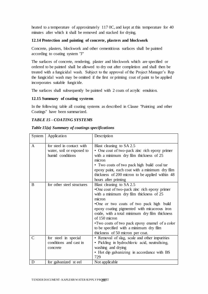
TENDER DOCUMENT- KAPLESIR WATER SUPPLY PROJECT 207
heated to a temperature of approximately 117 0C, and kept at this temperature for 40
minutes after which it shall be removed and stacked for drying.
12.14 Protection and painting of concrete, plasters and blockwork
Concrete, plasters, blockwork and other cementitious surfaces shall be painted
according to coating system "J"
The surfaces of concrete, rendering, plaster and blockwork which are specified or
ordered to be painted shall be allowed to dry out after completion and shall then be
treated with a fungicidal wash. Subject to the approval of the Project Manager‟s Rep
the fungicidal wash may be omitted if the first or priming coat of paint to be applied
incorporates suitable fungicide.
The surfaces shall subsequently be painted with 2 coats of acrylic emulsion.
12.15 Summary of coating systems
In the following table all coating systems as described in Clause "Painting and other
Coatings" have been summarized.
TABLE 15 - COATING SYSTEMS
Table 15(a) Summary of coatings specifications
System Application Description
A for steel in contact with water, soil or exposed to
humid conditions
Blast cleaning to SA 2.5 • One coat of two-pack zinc rich epoxy primer
with a minimum dry film thickness of 25 micron • Two coats of two pack high build coal tar
epoxy paint, each coat with a minimum dry film thickness of 200 micron to be applied within 48
hours after priming
B for other steel structures Blast cleaning to SA 2.5 •One coat of two-pack zinc rich epoxy primer with a minimum dry film thickness of 25
micron •One or two coats of two pack high build
epoxy coating pigmented with micaceous iron oxide, with a total minimum dry film thickness of 150 micron
•Two coats of two pack epoxy enamel of a color to be specified with a minimum dry film
thickness of 50 micron per coat.
C for steel in special conditions and cast in
concrete
• Removal of slag, scale and other impurities • Pickling in hydrochloric acid, neutralising,
washing and drying • Hot dip galvanizing in accordance with BS 729
D for galvanized st eel Not applicable
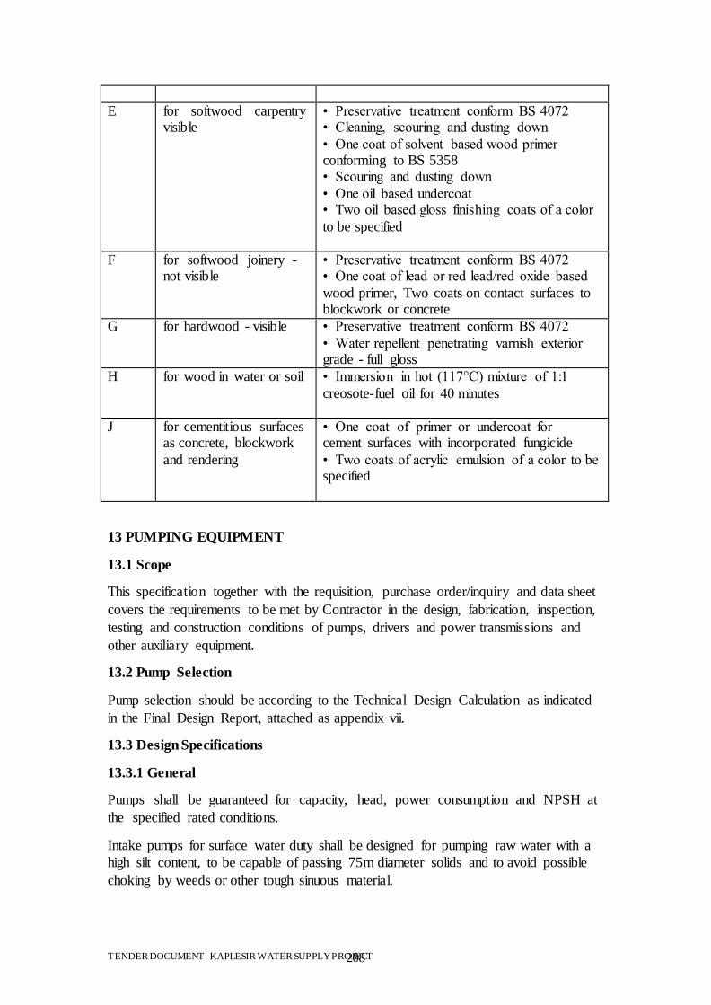
TENDER DOCUMENT- KAPLESIR WATER SUPPLY PROJECT 208
E for softwood carpentry visible
• Preservative treatment conform BS 4072 • Cleaning, scouring and dusting down
• One coat of solvent based wood primer conforming to BS 5358 • Scouring and dusting down
• One oil based undercoat • Two oil based gloss finishing coats of a color
to be specified
F for softwood joinery - not visible
• Preservative treatment conform BS 4072 • One coat of lead or red lead/red oxide based
wood primer, Two coats on contact surfaces to blockwork or concrete
G for hardwood - visible • Preservative treatment conform BS 4072
• Water repellent penetrating varnish exterior grade - full gloss
H for wood in water or soil • Immersion in hot (117°C) mixture of 1:1
creosote-fuel oil for 40 minutes
J for cementitious surfaces as concrete, blockwork
and rendering
• One coat of primer or undercoat for cement surfaces with incorporated fungicide
• Two coats of acrylic emulsion of a color to be specified
13 PUMPING EQUIPMENT
13.1 Scope
This specification together with the requisition, purchase order/inquiry and data sheet
covers the requirements to be met by Contractor in the design, fabrication, inspection,
testing and construction conditions of pumps, drivers and power transmissions and
other auxiliary equipment.
13.2 Pump Selection
Pump selection should be according to the Technical Design Calculation as indicated
in the Final Design Report, attached as appendix vii.
13.3 Design Specifications
13.3.1 General
Pumps shall be guaranteed for capacity, head, power consumption and NPSH at
the specified rated conditions.
Intake pumps for surface water duty shall be designed for pumping raw water with a
high silt content, to be capable of passing 75m diameter solids and to avoid possible
choking by weeds or other tough sinuous material.
TENDER DOCUMENT- KAPLESIR WATER SUPPLY PROJECT 209
Water velocities in the suction or delivery branches of a pump shall not exceed 3.5
m/s when the pump is operating within its specified duty range and within this
working range there shall be no discernible noise due to hydraulic turbulence or
cavitation within either the pump or its associated pipe-work and valves.
The pump efficiency shall be well maintained over the whole of the specified duty
range, even if this necessitates the use of a larger motor to provide the peak power
demand.
Pumps shall be arranged for priming by means of an adequate positive suction head in
all possible operating conditions.
Pumps rated point for furnished impellers shall not be beyond the best efficiency
point. Vendor shall make his endeavour to select the pumps having the best efficiency
point nearest to the rated point.
The NPSH requirements of the pumps, based on the 2% output drop criterion shall be
at least 1 m less than the NPSH available at every working condition.
The head/quantity characteristic of any pump shall be stable at all rates of flow
between closed valve and open valve and shall be steep enough to permit satisfactory
operation in parallel with other pumps under all conditions specified.
Effective means shall be provided for the collection of gland leakage water and piping
it to a suitable floor drain.
13.3.2 Drivers
The speed of any main pump shall not exceed 3000 rpm without approval of the
Project Manager‟s Rep. Pumps shall be driven by electric motors, unless otherwise
specified.
Motors shall have power ratings at least 125 % of break power, including all
losses through power transmissions at pump rated point.
13.3.3 Shaft and Shaft Sleeves
Shafts shall be made in one piece except for vertical pumps having a long shaft
subject to the Employer‟s approval, and shall be provided with sleeves securely
locked to the shaft. When the size of the pumps makes the use of shaft sleeves
impractical, the shaft shall be made of wear resistance material for packed pumps and
of a corrosion resistance material for pumps with mechanical seal.
Pump shafts shall be forged from a material compatible with the impellers. If the
pumps are fitted with packed glands, the shafts shall be provided with replaceable
sleeves where they pass through the gland.
13.3.4 Shaft Sealing
Pumps may be fitted with mechanical seals in place of packed glands only if they
have proved satisfactory over a long period when fitted to the design of pump in
question and with prior approval. They shall be designed for easy adjustment and seal
removal.
TENDER DOCUMENT- KAPLESIR WATER SUPPLY PROJECT 210
Where suction pressure is a vacuum, impellers shall be so arranged that stuffing box
pressure is positive. Otherwise, the stuffing box shall be effectively sealed to be
positive in pressure.
For conventional packing, lantern rings shall be used so that self-flushing can be
made. External flushing will be specified on the data sheets if necessary. Ample space
shall be provided for repacking without removing and dismantling any part, other than
gland components and guards.
Where mechanical seals are used, flushing port shall be provided near the seal surface
so as to remove heat effectively from the seal.
Hydraulically balanced seals shall be furnished for sealing pressure above 5 bar. For
tandem type mechanical seals, throttle bushing shall be provided.
13.3.5 Bearing and Bearing Houses
Unless otherwise specified, all pump bearings shall have a design running life of not
less than 100,000 hours. Bearings shall be designed for loading 20% in excess of
calculated maximum loading and shall be suitable for reverse rotation at 150% rated
speed or the maximum reverse speed the pump can reach in installed conditions when
driven backwards by reverse flow, if this is greater.
Bearing housings and brackets may be of cast iron for any services.
Bearing housings shall be effectively sealed against the invasion of water or dust.
Bearing lubrication system and cooling system shall be selected for the service
conditions, and shall be capable of operating continuously with the temperature at any
bearing housing not exceeding 70°C or ambient temperature plus 30°C, whichever is
lower.
Bearing cooling arrangements if used shall be designed on the closed-circuit principle.
Open discharge of cooling water into the pumping station drainage system is not
permissible.
Lubrication arrangements shall be designed to avoid any contamination of the
pumped fluid.
13.3.6 Nozzles and Miscellaneous Connections
Each pump shall be complete with all necessary ancillary equipment and fittings to
render the unit complete and ready for service. This shall include isolating valves,
non-return valves, air-valves, cooling water pipe- work, gland leakage pipe-work, air
release pipe-work, pressure gauges, gauge pipe-work, holding down bolts, access
platforms and other items as appropriate.
Pump casings shall have flanged suction and discharge nozzles. Flanged connections
shall be designed for bolting.
Flange ratings and facings will be specified on the data sheets by the Contractor.
TENDER DOCUMENT- KAPLESIR WATER SUPPLY PROJECT 211
The piping and equipment shall be designed and arranged for easy disassembly and
maintenance. Orifice opening shall not be less than 1.5 mm in diameter.
13.3.7 Materials of Construction
The pump impeller, shafting, sleeves, wear rings, casing, etc. shall be of suitable
material to cope with the pumped medium and the Contractor shall have satisfied
himself that sufficient detail has been provided to make this assessment.
Typical materials of pump construction have been given in the following Clauses and
are intended only as a general guide.
If the grade of materials of Manufacturer's selection is better than the specified one,
Manufacturer's standard materials may be used with the Project Manager‟s Rep's
approval.
Castings shall be sound and free of shrink or blow holes, scale, blisters and other
similar injurious casting defects. Cast iron shall not be repaired by welding without
specific approval of the Project Manager‟s Rep.
Casing corrosion allowances shall be 3 mm minimum for carbon and low alloy steels
and 0 mm for high alloy steels and non-ferrous materials unless otherwise specified.
Gaskets shall be of anti-corrosion type.
Copper or its alloys shall not be used for any components of auxiliary piping without
Project Manager‟s Rep's approval.
13.3.8 Impellers
Impellers of the maximum or the minimum diameters in relation to size of casings
shall not be used. Wearing rings shall be replaceable if furnished.
13.3.9 Couplings and Guards
Connections between horizontal pumps and drivers shall be made with suitable
flexible type couplings. Spacer type couplings shall be furnished.
Removable coupling guards made of steel plate shall be supplied and mounted by
Vendor for horizontal pumps. A limited end float coupling shall be provided when the
drivers have no thrust bearings.
13.3.10 Critical Speeds
The rotating assemblies shall be statically and dynamically balanced and designed so
that the first critical speed of a flexible shaft pump and its drive is at least 50% higher
than the maximum operating speed.
The first lateral critical speed of a stiff-shaft pump shall be at least 10 % over the
maximum operating speed. Where the rotating assemblies are small and any out of
balance forces are negligible this requirement will not be necessary. The manufacturer
is required to state whether balancing has been completed.
13.3.11 Pressure Lubrication System
TENDER DOCUMENT- KAPLESIR WATER SUPPLY PROJECT 212
A pressure lubrication system shall be furnished if specified by Employer or if
recommended by Vendor. All oil containing pressure components shall be of carbon
steel. Carbon steel oil pumps shall be pickled at Vendor's shop. Casings of shaft-
driven oil pumps may be made of cast iron.
The pressure lubrication system shall be incorporated into a base plate of the
equipment.
13.3.12 Pump Performance Guarantee
The pump performance guarantee shall relate to the flow rate, the total head and the
efficiency of the pump when tested at the manufacturer's works. The pump shall
operate at its design point within the acceptance tolerances for flow rate and total
head.
13.3.13 Marking and Painting
Nameplates and rotation arrows on pump drivers shall be 18-8 stainless steel or
monel, attached by pins of similar material at a readily visible location.
The following data as a minimum shall be clearly stamped on the name plates:
Item no.;
Manufacturer's name;
Pump serial number;
Date of manufacture;
Size and type;
Rated capacity (m³/h);
Rated pressure /head (m);
Rated speed (rpm).
13.4 Packing and Preparation for Shipping
Vendor shall clean all components, and preserve and protect them on the basis that
equipment and all accessories will be stored unprotected in the field for a minimum
period of 6 months.
All openings shall be provided with substantial metal closures. All tapped openings
shall be plugged.
All items shall be suitable packed, securely fastened and protected from damage
during shipment.
No package or container shall contain items of plant intended to be incorporated in
more than one part of the works.
Electrical plant shall be enclosed in sealed airtight packages with dehydrating salts
before being placed in packing cases on shock absorbent materials and secured by
fasten bolts.
TENDER DOCUMENT- KAPLESIR WATER SUPPLY PROJECT 213
13.5 Transportation
Equipment shall not be transported to job site as deck cargo without the Employer's
approval.
Centrifugal pumps shall be shipped as assembled units with drivers, unless otherwise
specified by the Project Manager‟s Rep.
No equipment shall be released for shipment from Manufacturer's shop until it has
been approved by the
Employer.
13.6 Horizontal Multi-stage High Pressure Pump Set
The pump shall be horizontally mounted multi-stage centrifugal type complete with
its motor and gearbox on a common base plate.
The axial loads shall be as far as possible hydraulically balanced. Where the pumped
medium has a fine abrasive content axial hydraulic loads shall be balanced by an oil
lubricated thrust bearing.
The dimensions of the pump shall be metric conforming to API 610 or its equivalent.
Inlet flanges shall conform to BS 4504 and delivery flanges shall conform to BS
1560: Part 2.
The bedplate shall be of substantial fabricated steel construction with floor fixing bolt
holes ready drilled. All holding down bolts, etc. shall be supplied with the unit.
The velocity at the entrance to the pump impeller shall not exceed 3.5 m/s.
Rotating assemblies of pumps shall be statically and dynamically balanced and shall
be designed so that the first critical speed of the pump and its drive is at least 50%
greater than the maximum operating speed.
The speed of any pump shall not exceed 3,000 rpm.
Glands may be fitted with suitable mechanical seals or conventional soft packing. The
gland arrangement shall be designed for ease of adjustment or removal of the seal or
packing material. Shafts shall be sleeved around the area of the gland when soft pack
glands are used.
The pump shaft bearings shall be oil lubricated and an oil lubricated thrust bearing
shall be included to prevent axial movement.
Lubrication arrangements shall be so designed that there is no contamination of the
pumped fluid.
The pump impeller, shafting and wear rings shall be of suitable material to cope with
the pumped medium and the Contractor shall have satisfied himself that sufficient
detail has been provided to make this assessment.
TENDER DOCUMENT- KAPLESIR WATER SUPPLY PROJECT 214
The pump and associated pipework shall be, wherever possible, arranged such that air
can be completely evacuated during priming. Where this is not possible, facilities
shall be provided for the removal of the entrained air. Adequate facilities shall be
provided for drainage of the pumps for inspection purposes.
Tappings shall be provided at both the suction and discharge flanges for pressure
gauge equipment.
13.7 Pipework
All pipework associated with the plant shall be of the galvanized heavy gauge steel
tubing type, to BS 1387:
1967. All bends, tees, unions and other fittings shall be of galvanized steel to BS 143
and shall be of the correct size and type for the steel tubing in use. Screwed or flanged
joints may be incorporated. Pipes shall be flanged to BS 4504: PN 10 where required
to make connections with plant items, and shall be designed for a pressure of not less
than 3 x relief valve pressure blow point.
Pipework shall be of the nominal bore stated and indicated on the Drawings.
Pipework shall be installed horizontally and vertically but shall fall in the direction of
air flow to facilitate draining of condensate. Automatic drains shall be fitted to
prevent the accumulation of condensate at low points in the system. The nominal fall
of the pipework shall be 1-in-80.
13.8 Pressure Relief Valves
Relief valves shall be of the poppet type. The valves shall be rated to pass at least
200% of the rated flow at the point of connection, at 150% of the working pressure.
The pressure setting of the valve shall be manually adjustable and secured with a
brass padlock. The valve shall be adjusted to the Maximum Safe Working Pressure at
the manufacturer's works and the setting secured with a brass padlock. A test
certificate and duplicate keys shall be provided. A wire lock and lead seal, stamped
with the pressure setting, may be used in place of the padlock.
13.9 Non-return Valves
Non-return valves shall allow uninterrupted flow in the required direction. On the
reversal of flow the valve shall close instantly and provide an airtight seal.
The valves shall be sized to accommodate the stated maximum flows in the pipe to
which they are fitted and at the working pressure stated.
They shall be suitable for mounting in a horizontal position.
Valves shall be of the multi-port frictionless element type to provide minimum
turbulence and pressure drop.
13.10 Drain Valves
TENDER DOCUMENT- KAPLESIR WATER SUPPLY PROJECT 215
Automatic drain valves shall be of the float-operated plug type designed to
automatically and continuously drain oil, water and other condensate from the
pipework.
They shall be sized for continuous operation at the maximum stated working pressure.
Where shown on the Drawings, the drain valves shall incorporate a manual
condensate drain facility.
13.11 Isolating Valves
All isolating valves shall be of the wedge gate type and shall be in compliance with
BS 5150. Valves may be flanged or fitted with double union ends to suit the size and
type of connecting pipework.
Valves shall be manually operated by means of a lever and shall be positioned so as to
be readily accessible to the operator.
13.12 Pressure and Vacuum Gauges
Gauges shall comply with BS 1780 and shall, unless otherwise specified, be of not
less than 100 mm diameter. Scales shall be calibrated in kg/cm2 with zero
representing atmospheric pressure. Lettering shall be black on a white background.
Where the working fluid is of a dirty or corrosive nature, gauges shall be protected
from the working fluid by a diaphragm or similar arrangement. All gauges shall be
fully protected from dust and water ingress and shall be provided with a suitable
isolation valve on the supply line adjacent to the gauge.
14 CHEMICAL PREPARATION AND DOSING PLANT
14.1 Hydrated Lime and Aluminum Sulphate Preparation and Dosing
Hydrated lime, supplied in the bagged powder, shall be made up as a slurry in suitably
coated steel preparation tanks. Each tank shall include at least:
powder feed hopper with cover;
dust extraction vent with attached filter;
500mm man hole with cover;
a motor driven slow speed paddle agitator;
overflow to sewer;
drain to sewer;
service water supply nozzle;
slurry discharge nozzle;
level indicator with calibrated scale.
All lime slurry lines shall have provisions for flushing with service water.
Distributors at the dosing points shall be installed to provide even distribution of the
hydrated lime slurry.
TENDER DOCUMENT- KAPLESIR WATER SUPPLY PROJECT 216
14.2 Vertical Tank Mixers
Mixers shall be suitable for operation in the chemical building adjacent to the lime
handling area without additional enclosures or protection. They shall be rated for
continuous operation and shall be a heavy duty industrial design.
Mixers may be designed for vertical or horizontal motor drives via a double reduction
gearbox incorporating change gears. Change gears shall be readily accessible for
removal and replacement. Gears shall be high precision match lapped spiral bevel or
helical types designed in accordance with AGMA standards. Bearings shall be taper
roller type with a B10 design life for not less than 30,000 hours. Gears and bearings
shall be splash
14.3 Pipework for Chlorine
All screwed pipework conveying chlorine or sulphur dioxide under pressure shall be
constructed from solid drawn steel tube to BS 1387 with heavy fittings in malleable
iron to BS 143 screwed to BS 21. Threaded joints shall be sealed using a jointing
compound compatible with chlorine or sulphur dioxide as appropriate. PTFE tape
shall not be used.
All flanged pipework conveying chlorine or sulphur dioxide gas under pressure shall
be carbon steel hot finished seamless, cold drawn seamless or electric resistance
welded to BS 3602 Class 23 or 27. Flanges
shall be raised face drilled to BS 1560 Class 150, double fillet welded, stress relieved
and radiographed. In the case of pipes of
25 mm diameter or less, magnetic particle examination may be substituted for
radiography. Joint rings shall be
2 mm thick compressed asbestos fibre tabbed to BS 2815 Grade B and shall fit within
the bolt circle. Prior to installation, the joint rings shall be impregnated or smeared
with graphite compound or similar compound compatible with chlorine or sulphur
dioxide.
Flexible tubes for final connections to drums or cylinders for gas withdrawal shall be
copper externally plated with silver or cadmium or alternatively shall be Monel. The
tubes shall be fitted with suitable screwed adaptors for making the connections to the
drums or cylinders.
All pipework for chlorine or sulphur dioxide gas under vacuum shall be rigid hi-
impact uPVC to BS 3505 or BS
3506 with solvent welded joints and fittings complying with the relevant parts of BS
4346.
Pipework shall be adequately supported throughout its length. Sleeves shall be used
where pipework passes through walls. All apertures shall be properly sealed with a
chlorine and sulphur dioxide resistant compound.
TENDER DOCUMENT- KAPLESIR WATER SUPPLY PROJECT 217
Pipework within buildings shall not be run in floor ducts unless otherwise approved
by the Project Manager‟s Rep.
14.4 Valves for Chlorine
Isolating valves in pipework conveying chlorine or sulphur dioxide under pressure
shall be interchangeable and specifically designed for chlorine or sulphur dioxide
service as appropriate.
Valves shall be provided at each end of flexible connecting tubes to drums and
cylinders and shall be needle valves having PN10 class forged bodies in silver plated
brass with screwed end connections and shall be of glandless design with a nickel
diaphragm. The valve shall be operated by means of a hand wheel.
All other isolation valves shall be sleeved plug valves having PN10 class forged
bodies in carbon steel with integral end connections, tapered plug in Monel with pure
PTFE sleeve and top seal arrangement with PTFE diaphragm and delta seal ring, back
up metal diaphragm, floating thrust collar, electrostatic eliminator, four bolt cover and
three point self-aligning plug adjustment. The valve design shall ensure that excess
pressure in the plug and body cavity of the closed valve is relieved spontaneously
towards the direction of high pressure. The valve shall be operated by a forged steel
wrench with padlocking facility in the closed position or otherwise by power actuator
as specified elsewhere.
Flanged valves shall have raised face flanges drilled to BS 1560 Class PN10.
All valves shall be supplied degreased and dried for chlorine service and maintained
in this condition for inclusion in the Works.
A works test certificate is required for each valve covering hydrostatic testing of the
shell and seat and air testing of the seat in accordance with BS 5146 Part 1. The gauge
pressure for the air test shall be 10 bars.
14.5 Pipeline Identification
All pipework shall be banded with vinyl laminated identification tape to enable
individual lines to be identified throughout their length. Bands shall also be applied
above floor plates, on both sides of walls or bulkheads, on both sides of valves, at
branches and adjacent to equipment connections.
The individual bands shall be 50 mm wide, colour coded generally in accordance with
BS 1710 to indicate the fluid conveyed and shall have a flow direction arrow and
lettering to signify the sampling or dosing point served and, where applicable, the
function or the chemical.
Bands for toxic gas and chemical solution lines shall incorporate danger warning
markers (black/yellow diagonal stripes) 50 mm wide giving a composite width of 150
mm.
Steel pipework carrying chlorine or sulphur dioxide shall be painted in the following
colours to BS 381C in place of banding: • Chlorine pipework: Golden yellow,
colour Nr 356
TENDER DOCUMENT- KAPLESIR WATER SUPPLY PROJECT 218
14.6 Protective clothing and safety equipment
Sets of PVC overalls, gloves, goggles and rubber boots all in medium sizes, obtained
from an approved supplier, shall be provided as necessary.
14.7 Safety Showers and Eyewash
Safety showers shall be hand and treadle operated and shall continue until the valve is
manually closed. The water shall be heated by trace tape or an immersion heater to
between 25°C and 35°C under normal ambient conditions. The shower shall supply
90 to 140 l/min through a 60° spray angle at a minimum supply pressure of 2.2 bar. A
header tank shall be provided where insufficient supply pressure is available.
15 ELECTRICAL WORKS
15.1 General
15.1.1 Regulations and standards
The electrical installation shall comply with all relevant statutory regulations and
standards current at date of tender, unless otherwise indicated within this
Specification. In general the following shall apply:
The IEE Regulations for Electrical Installations, 16th Edition. The Health and Safety
at Work Act, etc. Factories Act (UK) British Standards (BS) British Standards Codes
of Practice (CP) International Electrotechnical Commission (IEC) Electric
Regulations Commission (ERC) guidelines.
If no standard is specified, the relevant British Standard or, in the absence of such
standard, International standard shall apply.
15.1.2 Abbreviations of electrical terms
For the purpose of this Specification the following abbreviations of electrical terms
have been used:
L1 - red phase
L2 - yellow phase
L3 - blue phase
N - neutral
ac - alternating current
dc - direct current
A - amp
mA - milliamp
V - volt
kW - kilowatt
kWH - kilowatt hour
TENDER DOCUMENT- KAPLESIR WATER SUPPLY PROJECT 219
kVAr - kilovar
kVA - kilovolt amp
MVA - megavolt amp
Hz - hertz (cycles per second)
SP - single pole
SPN - single pole and neutral
DP - double pole
TP - triple pole
TPN - triple pole and neutral
SPSwN - Single pole and switched neutral
TPSwN - triple pole and switched neutral
MCB - miniature circuit breaker
MCCB - moulded case circuit breaker
RCD - residual current device
MCC - motor control centre
15.1.2 Polarity
The polarity of all electrical apparatus used for the Works specified shall be arranged
as follows:
for two pole apparatus the phase of 'live' pole at the top (or left hand side) and the
neutral or 'earthed' pole at the bottom (or right hand side), for three or four pole
apparatus the phases in order of red, yellow, blue and neutral reading from top to
bottom or left to right in the case of vertical and horizontal lay outs respectively and
as viewed from the front.
All non flexible cables shall be so connected between main switchboards, distribution
boards, plant and accessories so that the correct sequence or phase colors are
preserved throughout the system.
All non flexible cable cores shall be identified with phase colors for three and four
wire circuits. Single phase circuits shall be red and black.
15.1.3 Voltages and frequencies
Unless otherwise indicated in the Particular Specification, all apparatus and wiring
shall be suitable for use with the Kenyan Standard Electrical Power Supply, which
conforms to the EC standard of 3 phase, 4 wire, 415/220 volt, 50 Hz earthed neutral
supply. The supply waveform shall be a sine wave.
Supplies for control, tripping, alarm and indication circuits shall be 24 V dc. Circuit
breaker spring charging motors shall also operate at 24 V dc.
TENDER DOCUMENT- KAPLESIR WATER SUPPLY PROJECT 220
Control voltage within motor starters shall be 110 V ac. Extension of 110 V circuits
outside the starter shall not be permitted except for the circuit to the emergency stop
button, where fitted.
Tap changer motors and electrical panel heating and lighting shall operate at 230 V,
single phase. All equipment operating at 230 V shall be fully shrouded and clearly
labelled.
Where 230 V lighting and heating is used within a panel which otherwise contains
equipment with a nominal operating voltage of 24 V, the 220 V equipment shall be
insulated, sheathed and protected in accordance with standard practice for installing
such equipment in buildings. No live terminals shall be accessible without the use of
tools, no single- insulated wires shall be used, and no 220 V cables shall share cable
trays or other routes with 24 V circuits.
All references to voltages shall relate to the nominal, or rated value of the supply.
15.1.4 Units of measurement
All information shall be in metric SI units. Where plant design exist in imperial units,
the dimensions and tolerances of lay outs and terminal points shall be presented in SI
units to a degree of accuracy which permits the precise matching of existing
components.
15.1.5 Electricity supplies
The Contractor shall liaise with the relevant Utility Company to undertake any
testing and inspection necessary for the electricity supplies to be connected when
required. On completion of the tests and inspections, not less than two weeks prior to
the power supply being required, the Contractor shall supply to the Project Manager‟s
Rep a copy of his Electrical Installation Completion Certificate and of the test
certificates.
15.1.6 Electrical safety
The Contractor shall be responsible for the electrical safety of all equipment supplied
and installed. Whilst any equipment is being installed or tested, the Contractor shall
ensure that all necessary precautions are taken to safeguard personnel working on site.
If necessary, this shall include erecting warning notices and fencing off areas which
are considered to pose a risk.
The Contractor shall be responsible for ensuring that the electrical installation is
carried out by competent personnel and that the work is carried out in accordance with
standard procedures and test requirements. Before any piece of apparatus is energized
it shall be thoroughly examined for the presence of dirt, water or other foreign bodies.
15.2 Switchboard construction
15.2.1 General
This section shall apply to the construction of all panels housing electrical apparatus,
including but not limited to the following:
TENDER DOCUMENT- KAPLESIR WATER SUPPLY PROJECT 221
switchboards;
circuit breakers;
control panels;
monitoring or supervising panels;
distribution boards - control panels;
marshalling panels;
15.2.2 Safety
switch-disconnecter is open and connections within the compartment are isolated or;
the compartment operate at a voltage not greater than 55 volts.
Where a test facility is provided for use with the door or cover open the provisions of
(b) shall apply. Connections which may be live with the door or cover open shall be
suitably labelled.
Bolted covers on compartments incorporating live connections shall bear a suitable
warning label.
Labelled isolators, fuses or links shall be provided so that relays, controls and
instruments may be isolated but keep other essential circuits energized.
18.2.3 General construction standard
Switchboards, cubicles and enclosures for electrical equipment shall be constructed in
sheet steel not less than 2.0 mm thick and suitably braced to form a rigid structure.
Exterior edges and corners shall be rounded and the use of externally visible assembly
bolts or similar shall be avoided.
The design shall provide protection against dust, damp and entry of vermin. Gaskets
shall be fitted to doors and removable panels. Ventilation and cooling shall be by
natural air circulation. The enclosed equipment shall be designed to operate without
forced ventilation under the ambient conditions specified or to be expected.
Unless specified otherwise, switchboards, cubicles and enclosures shall be floor-
standing with lockable hinged front doors and bolted removable rear panels for access
to live equipment such as busbars and terminals.
Each section shall be separately accessible without disturbance to other sections for
maintenance and inspection. Live parts with voltages greater than 55 V to earth within
the section shall either be isolated automatically when the section door is opened, or
be fitted with insulating barriers to prevent accidental contact by personnel. Parts still
live when the unit is isolated shall be labelled "Danger Live". Where integral fuse or
MCB distribution boards are incorporated, access to fuse carriers and MCB's shall be
possible without isolating the fuse or MCB distribution board. With the operator's
door open and with fuses and MCB's in place, the degree of protection of such
distribution boards shall be not less than IP20.
TENDER DOCUMENT- KAPLESIR WATER SUPPLY PROJECT 222
A clear access of not less than 1000 mm, and preferably 1500 mm, shall be given at
the rear and both ends of the panel.
Controls and switches mounted on any control panel section of a switchboard shall be
installed in the height range 750mm to 200mm; indicating instruments 900mm to
1800mm; recorders 900mm to 1400mm. This requirement shall not be applied to
starters or feeder sections.
Switchboards shall be equipped with a power transformer and 2 No. 15 A, 110 Vac
(+55 V) RCCB protected sockets, suitable for use with electric hand tools.
Switchboards shall additional have 2 No. 13 A, 230 Vac RCCB protected sockets.
Each section or cubicle of the board shall be clearly labelled with the circuit name and
number, and the reference number of the section. The panel shall have a name plate
carrying the manufacturer's name, address, reference, and year of construction of the
panel.
Cubicles and enclosures shall be earthed. Where a number of cubicles are bolted
together, earthing shall be provided via a continuous high conductivity copper bar of
minimum cross section 25mm x 6mm running the length of the panel. Terminals shall
be provided for the connection of earthing from the metal cladding or armouring of
incoming and outgoing cables. Holes shall be left at each end of the bar for
connection to the main station earth and future extension. The bar shall be fault rated
at not less than that of the associated equipment. Warning labels and instructions for
earthing and isolating shall be fitted in each switch compartment. Front access doors
shall open not less than 120° and shall be fitted with a locking handle and non-ferrous
lift-off hinges which shall be captive when the door is closed. Locking combinations
requiring different keys shall be approved before manufacture. The door shall be
secured by captive screws or locking handles of sufficient number to ensure firm
pressure on the door seal around the whole periphery. The door shall be mechanically
prevented from opening before isolation of the live parts within. All doors shall be
separately earthed to the main frame. Earthing via the door hinge will not be accepted.
Cables shall enter through 3mm thick undrilled removable steel or brass (for single
core cables) gland plates mounted at least 250mm above switchboard base level.
Access to both sides of gland plates for
gland tightening shall be readily available. Gland plate knockouts will only be
accepted for individually mounted starters and small power distribution boards.
Lifting eyeholes shall be provided at each top corner of each section of the
switchboard and shall be removed and replaced with blanking bolts after installation.
Cubicles and enclosures for outdoor locations shall be fitted with lockable outside
doors and a housing so designed that all controls, instruments and such like are fully
enclosed and the whole assembly is weatherproof and vandal proof. The doors shall
be fitted with stays to prevent overstraining of the hinge fixing, and allow fixing of
the doors in the open position. Switchboards inside cubicles shall also be
weatherproof to allow operation of the controls when the outside cubicle doors are
open during inclement weather.
TENDER DOCUMENT- KAPLESIR WATER SUPPLY PROJECT 223
When specified, a double skin roof shall be fitted over the whole assembly to give
added protection against direct sunlight.
LV enclosures shall be constructed with a protection ratings of at least the following:
for outdoor installation IP 65; for indoor installation IP 54.
Switchboard, cubicle and enclosure construction shall be capable of withstanding
without damage the fault current of the system. HV enclosures shall be constructed to
the latest Standards with IP ratings equal to those for LV enclosures.
Protective coatings shall be applied at the place of manufacture and before installation
of its internal electrical fittings.
16.2.4 Switchboard small wiring
Switchboard wiring shall be carried out in 600/1000 V PVC insulated cable to
BS6231. The conductors shall be stranded or flexible (where applicable): solid cores
will not be accepted. The conductor size shall be not less than 1.5 mm² for control and
indication circuits and not less than 2.5 mm² for CT secondary circuits.
Wiring within the switchboard shall be marked with ferrules at each end for
identification. The letters and numbers used shall correspond with the switchboard
wiring diagram.
- -
- - green/yellow
The wiring shall be neatly laced and cleated to the switchboard structure or contained
within purpose designed plastic trunking and arranged so that access to equipment is
not impeded. Where trunking is
used the ratio of effective cross sectional area of the cables shall be not greater than
40% of the trunking area. Where wiring passes through metalwork the access hole
shall be fitted with a suitable grommet.
Every wire shall be identified by indelibly marked circular ferrules at each end. Slip-
on, or 'u' type ferrules will not be accepted. Identification shall correspond with the
wiring diagram.
Wiring between cubicles or panel sections shall be terminated on terminal blocks at
each end.
Wiring onto hinged doors or plates which is subject to movement shall be run in
flexible circular section trunking and shall be supported securely at both ends of the
moving section. Adhesive fixings of the ends of the trunking will not be accepted.
Crimped flat blades shall be applied to all wire ends to ensure sound connection to
terminal blocks and all circuit components.
Small wiring used for control, extra low voltage and instrument signals which are
likely to be affected by interference shall be screened and/or spaced from each other
and power cables to ensure no distortion or mal-operation.
TENDER DOCUMENT- KAPLESIR WATER SUPPLY PROJECT 224
16.2.5 Switchboard busbars and primary connections
All busbars and primary connections shall be of high conductivity copper and
comply with the latest Standards. The mechanical and dielectric strengths of busbars
and connection supports shall be able to withstand without damage the worst
conditions of electrical surge which can occur on the installation. The busbars shall be
capable of carrying full rated current continuously without exceeding temperature rise
limits to the latest Standards.
The busbars, assemblies and connections of equipment shall be of a type which does
not rely solely on air for insulation purposes. The covering material shall be non-
deteriorating at the rated short-time maximum temperature of the busbars and shall
have such thickness as is required to withstand rated line to line voltage between
busbar and a conducting object on the exterior of the covering material for a period of
not less than60 seconds.
Where independent certification of busbar withstand and continuous rating is not
available the Contractor shall include tests to demonstrate the suitability of the
equipment.
Busbars and primary connections shall be housed in an air-insulated enclosure
segregated by barriers. Direct access to live bars shall not be possible. Access to
busbars and connections shall be only by removal of bolted covers. Suitable warning
labels shall be provided externally on covers and internally on shutters. Busbars shall
be identified by colored banks opened at not more than 1000mm and in each
compartment.
Baffles shall be provided to prevent the accidental entry of tools, etc. whilst
maintenance work is being carried out in the vicinity of the chambers.
Busbar systems shall have a short time rating not less than that of the associated
switchgear. Busbars shall be extensible at both ends.
The conductors shall be separated and supported with the appropriate clearances in air
or shall be otherwise adequately insulated or encapsulated.
16.3 Switchboard components
16.3.1 General
This section shall apply to components used in all panels housing electrical apparatus,
including but not limited to the following:
switchboards;
motor control centres;
circuit breakers;
control panels;
monitoring or supervisory panels;
distribution boards;
marshalling panels;
interface panels;
TENDER DOCUMENT- KAPLESIR WATER SUPPLY PROJECT 225
local control panels;
16.3.2 Indicating Instruments and Meters
All instruments and meters shall be flush mounted, 96mm x 96mm minimum size and
of the same pattern and appearance throughout. They shall be back connected and be
similarly protected to maintain the environmental protection standard of the
equipment enclosure on which they are mounted. Those which perform similar duties
shall be of uniform type and manufacture.
Indicating instruments shall have black marking on a white background, a full scale
deflection of 270° and be fitted with an externally accessible zero adjuster.
They shall have no parallax error and their normal maximum reading shall be
approximately 60% full scale deflection.
Ammeters in motor starter circuits shall be capable of withstanding the starting
current and shall have a compressed overload scale. The scale shall be clearly marked
with a red line indicating normal full load current.
Indicating instruments shall comply with BS 89 (IEC 51) and shall be of industrial
grade accuracy, (+5%) unless otherwise specified.
Kilowatt-hour meters shall comply with the latest Standards and shall have an
accuracy of +1% unless otherwise specified.
Where portable instruments are specified they shall be of sub-standard accuracy
(+1%). Instruments shall be positioned between 1800 mm and 750 mm above finished
floor level.
16.3.3 Indicator Lights
Indicator lights shall be of uniform type as far as possible, to minimize spares
requirements. Glasses and bulbs shall be easily removable without the use of a tool.
Indicator lights shall be not less than 20 mm diameter and shall be of the projecting
type so they can be seen from the front and side of the switchboard. They shall be
visible under bright sunlight conditions.
The lights shall be under-run to give long life either by use of a resistor to limit
voltage to 90% of normal value, or by using higher voltage lamps.
Alternatively the lights shall be transformer operated or battery operated where a
battery is available.
Colors of indicator lights shall generally comply with the latest Standards. The
diffuser glasses shall be colored and the bulbs shall be clear.
LED indicator lights shall not be used except where they form part of proprietary
equipment.
All components, doors and removable covers shall be labelled. Fuse carriers shall also
have labels which state the fuse rating to be fitted. Each cubicle door shall bear an
TENDER DOCUMENT- KAPLESIR WATER SUPPLY PROJECT 226
identification label (minimum letter size 8mm) and each switchboard and enclosure
shall bear an overall identification label (minimum letter size 12mm).
Light colors shall comply with BS 4099 as follows:
power on - white
running - green
tripped/alarm - red
status (open, closed, etc.) - blue
ready to start - blue
warning (no imminent danger) - amber
16.3.4 Labels
All designating labels shall be of traffolyte or similar finished white with engraved
letters and numbers filled with black and fixed by non-rusting screws.
Danger and warning labels shall be of similar material finished in yellow with red
letters and numbers. Edges of labels shall be bevelled and lettering shall be at least
4mm high.
16.3.5 Push Buttons
Colors of push buttons shall generally comply with the latest Standards and in
particular shall be as follows:
stop, emergency stop - red
start - green
jogging/inching - black
reset (when not also acting as stop)- blue
lamp test - blue
override/alarm accept - yellow
Emergency stop push buttons shall have enforced contact separation. They shall be
connected in the control circuits so they trip the circuit under all conditions.
16.3.6 Terminal Blocks
Terminal blocks shall be of non-brittle material, screw-clamp, rail mounted type to
VDE 0611. Pinch screw type blocks shall not be used.
At least 20% spare terminals shall be provided at all blocks.
Every terminal block shall have a clear plastic clip-on cover running the full length of
the block to prevent accidental contact with live terminals.
Removable DIN rail terminals shall be provided for all wiring, mounted at an angle to
provide ease of access, positioned not less than 150mm from gland plates, doors or
covers.
Power, control, earth and end stop terminals shall be provided and terminals shall be
grouped and separated by barriers according to their voltage level and function.
TENDER DOCUMENT- KAPLESIR WATER SUPPLY PROJECT 227
No more than two conductors may be connected to one side of a terminal. Outgoing
cables shall be wired so that outgoing wiring is connected to one side only.
Terminal blocks shall be mounted vertically at the side of the enclosure and set
obliquely towards the rear doors.
Every terminal block shall have a clear plastic clip-on cover running the full length of
the block to prevent accidental contact with live terminals.
Blocks at different voltages or phases shall be grouped and labelled accordingly.
16.3.7 Test Terminal Blocks
Test terminal blocks shall be provided for secondary injection and testing of relays.
A metering block shall be provided for the connection of portable sub-standard
instruments for plant testing. Test terminal blocks shall be provided with shorting
links or be of a type suitable for use with portable testplug- in equipment.
16.3.8 Control, Auxiliary, and Selector Switches
Control and Selector Switches shall conform to the latest Standard.
Control Switches shall be of the three position type with a spring return action to a
central neutral position. They shall be labelled.
Electrically operated circuit-breakers shall be fitted with a control switch labelled
Open/N/Close. These shall be of the pistol grip type with a spring return to the neutral
position. The switch shall be lockable in the neutral position.
Selector switches shall make before break and shall remain in the position selected
and be lockable in that position. They shall have spade shaped handles and each
position shall be labelled.
Contacts of all switches shall be shrouded.
A minimum of four spare auxiliary switches, two normally open and two normally
closed shall be provided for each circuit breaker and contactor.
16.4 Switchboard Ancillary Equipment
"treatment for electric shock" metal enamel instruction plate suitable for screen
attachment; Operating handles, tools, spares and lubricants as specified elsewhere.
16.5 Voltage transformers
Voltage transformers shall comply with the latest Standards. The secondary winding
shall produce an output line voltage of 110 V, three phase. The accuracy class and VA
rating shall be as specified or shall match the requirements of all connected
instruments and relays.
The primary circuit shall be protected by HRC fuses having a short-circuit rating of
not less than that of the switchgear. The connections between the fuses and the
TENDER DOCUMENT- KAPLESIR WATER SUPPLY PROJECT 228
switchgear primary conductors shall be of sufficient cross section and be supported to
withstand the short-circuit rating of the switchgear.
The secondary circuit shall be protected by HRC fuses mounted as close as possible to
the secondary terminals. Fuses shall be accessible without the need for isolating the
switchgear.
Isolatable voltage transformers shall have the facility for padlocking in the service
position. Safety shutters shall automatically cover the busbar spouts when the
transformer is withdrawn. Shutters shall have the facility for padlocking in the closed
position.
16.6 Current transformers
Current transformers shall comply with the latest Standards and shall be of the
wound-primary or barprimary type according to ratio required. All current
transformers shall have a short-time current rating of not less than that of the switch
panel in which they are incorporated. For bar-primary current transformers this rating
shall be for a period of 3 seconds. For wound-primary patterns the rating shall
preferably be for a period of 3 seconds but may be reduced to not less than 0.5 second
subject to the Project Manager‟s Rep 's approval.
Identification labels shall be fitted giving type, ratio, rating, output and serial
numbers.
Current transformers shall be of Class 1 accuracy for use with measuring instruments
and Class 10P for use with protective relays.
Class 5P shall be used for combined overcurrent and earth fault protection of the
inverse time overcurrent type.
The secondary windings of each set of star-connected three phase current
transformers shall be earthed at one point only, via a bolted link.
Separate sets of CTs shall be used for metering and protection.
Shorting links shall be provided at test blocks.
16.6.1 Control transformers
Unless otherwise specified all contactor control circuit supplies shall be obtained from
the 110 V secondary winding of a single phase integral control transformer.
Transformers shall be of the double wound pattern in accordance with the latest
Standards and shall have an earth screen between primary and secondary windings.
One leg of the secondary winding shall be earthed. The primary winding shall be
protected by cartridge fuses, and the secondary winding shall be protected by a fuse
and link.
A spare control transformer shall be provided with each new switchboard.
16.6.2 Anti-condensation heaters
TENDER DOCUMENT- KAPLESIR WATER SUPPLY PROJECT 229
Anti-condensation heaters shall be fitted to:
wall mounted enclosures;
individual floor mounted enclosures;
each vertical section of single tier switchgear or control gear;
each tier of multi-tier enclosures.
Each heater shall be controlled by its own thermostat, ON/OFF switch and fuses or
MCB. Heaters in exposed positions shall be fitted with a safety guard.
Each section of the panel shall contain an anti-condensation heater, rotary isolating
switch, and HRC fuse or appropriate protective device. A bus-wired single phase
supply controlled by a calibrated adjustable thermostat shall energies all panel heaters.
16.7 Protective relays
16.7.1 General
Protective relays shall be mounted on the front of the switchgear or relay panel in
such a position that operation and maintenance can be conveniently carried out.
Auxiliary relays may be mounted inside a cubicle provided that they are readily
accessible.
Each relay shall be contained in a dust proof case with a clear front cover. All metal
bases and frames shall be earthed except where there are technical reasons where this
is impracticable.
All relay contacts shall be capable of making the maximum current which can occur
in the circuit without causing damage to the contacts.
Relays shall have provision for testing the operation and calibration without
disconnecting the permanent wiring.
Flush, draw out type relays are preferred. Each relay shall have an indicator device to
show when the relay has operated and if necessary, which phase element. Each
indicator shall be hand resettable. Resetting devices shall not require the removal or
opening of the relay. It shall not be possible to operate the relay without opening the
case.
Where solid state relays are specified, these shall be of the module type comprising a
number of plug in elements allowing interchange of functions. Each of the protection
elements shall have adjustable controls for current and time settings as required. Solid
state relays of a particular type shall have interchangeable protective elements with
other similar relays supplied under this Contract.
All relays shall be provided with a name plate giving manufacturer, type, serial
number, year of manufacture, ratings and connection diagram.
All relays using a DC auxiliary supply shall operate down to 60% of the nominal
voltage and up to boost charge voltage of the battery.
Protection relays shall comply with the latest Standards where appropriate and shall
conform to the following provisions:
TENDER DOCUMENT- KAPLESIR WATER SUPPLY PROJECT 230
16.7.2 Over current and earth fault protection
Relays shall be of the attracted armature or rotating disc type having instantaneous,
inverse or very inverse definite minimum time, directional or non-directional
characteristics as specified.
16.7.3 Under Frequency Relays
The setting range shall be variable between -10% and + 2% from the rated frequency.
Two different settings shall be provided to give alarm and trip facilities. A low pass
filter unit shall be fitted where the harmonic distortion exceed 5% of the fundamental.
16.7.4 Under and over-voltage relays
Variable settings shall be provided as required together with a 0 to 5 second time
delay.
16.7.5 DC trip relays
Relays shall be suitable for operating with the voltage reduced to 60% of normal.
16.8 Circuit breakers
16.8.1 High voltage circuit breakers
Circuit breakers shall be vacuum or SF6 type as specified. The equipment shall
comply with the latest Standards as appropriate and be fully rated for the ambient
conditions specified.
Circuit breakers shall be capable of clearing any fault condition which may occur on
the system without damage to equipment or personnel.
Circuit breakers of the same pattern and rating shall be interchangeable.
Vacuum circuit breakers shall comprise separate vacuum interrupters designed to
prevent welding of contacts and sharp current chopping during fault interruption or
switching or motor loads.
All circuit breakers shall be provided with operating mechanisms as detailed in the
t manual
spring with electrical release;
All operating mechanisms shall have mechanical 'ON' and 'OFF' indicators and a
manual trip device fitted with means for locking. Hand charged and motor charged
spring mechanisms shall have mechanical indicators to show 'SPRINGS CHARGED'
and 'SPRINGS DISCHARGED'.
The operating mechanisms of hand charged and motor charged spring types shall be
arranged so that release of the springs to close the circuit breaker can only be
achieved by a deliberate action. It shall not be possible for vibration or mechanical
shocks to release the charged springs. Motor charged spring mechanisms shall be
arranged to that charging is initiated automatically following a discharge. The
necessary limit stops and switches for the automatic control of the charging shall form
TENDER DOCUMENT- KAPLESIR WATER SUPPLY PROJECT 231
an integral part of the mechanism. The facility shall be provided to hand charge a
motor charged spring mechanism.
Spring operated mechanisms shall be provided with volt-free contacts to give
indication that the springs are charged.
To facilitate maintenance and the adjustment of contacts, it shall be possible to 'slow-
close' the circuit breaker but this operation shall only be possible in the fully
withdrawn position. Any operating handle or lever necessary shall be supplied.
breaker cannot be racked into or out of the service or earth position whilst it is closed.
breaker can only be closed when fully engaged in the service, earth, or fully isolated
ition without
breaker cannot be 'slow-
charged or motor charged spring mechanisms, the springs cannot be discharged until
they have been fully charged or until the means for charging has been fully removed
can be effected only by the manual device on the operating mechanism;
Where mechanical key interlocking is employed, tripping of a closed circuit breaker
shall not occur if any attempt is made to remove the trapped key from the mechanism.
Circuit and/or busbar earthing shall be by the transfer circuit-breaker method without
the requirements of any loose attachments. The earthing operation shall be completed
by the closing of the circuit breaker by its normal operating means using local control.
Selection of either circuit or busbar earthing shall be possible only after the circuit
breaker has been fully isolated. Mechanical key interlocks shall remain operative
when the circuit breaker is in either earthing position.
Facilities shall be provided on all incoming and feeder circuit breakers for earthing
the circuit side. On at least one circuit breaker panel in any section of busbars,
facilities shall be provided for busbar earthing.
A set of safety shutters shall be provided to cover each three phase group of stationary
isolating contacts. The shutters shall be opened automatically by a positive drive from
the circuit breaker moving portion and when closed shall prevent access to the
stationary isolating contacts. When the circuit breaker is withdrawn each set shall be
capable of being individually operated and of being padlocked in the closed position.
Shutters in bus-section units shall be colored red and shall be labelled with a large
white arrow pointing in the direction of the section of busbars to which the contacts
are connected.
Circuit breaker moving portions shall be fitted with positive guides to ensure correct
alignment of the isolating contacts in both the service and the earth positions.
16.8.2 Low voltage circuit breakers
TENDER DOCUMENT- KAPLESIR WATER SUPPLY PROJECT 232
All 380V circuit breakers for incoming circuits, and bus section circuits on 380V
switchboards and interconnector circuits shall be of the air break metal clad type
complying with the requirements of the latest Standards.
Circuit breakers shall switch three phase poles. The neutral pole shall either be
switched or established through a bolted link. Access to the link shall not be possible
when the equipment is in the "Service Position".
Provision shall be made for easy access to the circuit breaker contacts for
maintenance purposes.
Arc chutes shall be so arranged that the emission of hot gasses shall not damage any
part of the equipment.
16.8.3 Moulded case circuit breakers
Moulded case circuit breakers (MCCBs) shall be manufactured to the latest Standards.
MCCBs shall have thermal overload and adjustable magnetic short circuit tripping
devices with a tripfree mechanism to ensure that the contacts cannot be held closed
against a fault. Contacts shall be silver tungsten tipped and shall operate with a
wiping, arc resisting material and incorporate arc chutes based on the de- ionising
principle.
MCCBs shall have a factory calibrated and sealed trip unit, interchangeable with
similar units for varying the rating of the circuit breaker.
Where dust and damp proof enclosures are to be used, then the circuit breakers shall
be fully enclosed in a case with a gasketted door. Circuit breakers mounted in a
composite control panel shall be segregated from other equipment and have a
matching purpose-made cover plate. Where possible, circuit breakers shall be
mounted vertically and be arranged so that one breaker can be removed without
interfering with other circuit breakers. The switch dolly and protruding face shall be
engraved with the circuit rating and the ON and OFF positions.
Tripping due to overload or short-circuit shall be clearly indicated by the handle
automatically assuming a position midway between the manual ON and OFF
positions. To reset from the 'tripped' position, the dolly shall first pass through the
OFF position. All phase poles shall operate simultaneously.
MCCB's used for short circuit protection (only) in motor starters shall provide
instantaneous short circuit protection by means of an adjustable magnetic element on
each pole. The adjustment knob(s) shall have the end and mid-setting points marked
and adjustment shall follow a linear scale so that each point has a significant value
within calibration tolerances. MCCB's shall not be used to provide thermal protection
or switching of motors.
MCCB's shall be ambient temperature compensated. Compensation shall allow the
breaker to carry rated current between 25°C and 50°C with tripping characteristics
that are approximately the same throughout this temperature range.
16.8.4 Miniature circuit breakers
TENDER DOCUMENT- KAPLESIR WATER SUPPLY PROJECT 233
Miniature circuit breakers (MCBs) shall be manufactured and tested to the latest
Standards.
MCBs shall have a short circuit rating of at least M4 and shall be Type 3 with a
breaking capacity of 4.5 kA at220/380 V unless otherwise specified.
The fault capacity of the MCB shall be not less than that of the switchboard. If this is
not the case, back up HRC fuses shall be fitted. MCB‟s for dc circuits shall provide a
double break (one pole protected plus one switched).
16.9 Fused-switches and disconnecter combination devices
16.9.1 General
Fused switch disconnecters, switch-disconnecters and disconnecters, shall be rated at
500 V and shall be to the latest Standards.
Fuse switch disconnecters shall be of the air break triple pole or single pole and
neutral type. They shall have not more than one fuse in any one pole. The neutral shall
be either switched or taken through a removable link. If a switched neutral is required,
the neutral shall be arranged to make first and break. A separate brass earth terminal
shall be provided.
Operating mechanisms shall be of the independent spring type and fitted with
mechanical ON and OFF indicators. Operating handles shall be of semi-flush or
telescopic pattern to reduce front projection to a minimum.
Disconnecters shall be identical to fuse-switches but the fuse links shall be replaced
by hard drawn high conductivity copper links.
Facilities for locking the operating handles by padlock shall be provided.
All switch-disconnecters shall be rated to make the full short circuit current of the
system. Units used on distribution circuits shall be rated to break full load current and
units used in motor starters shall be rated to break stalled motor current.
16.9.2 Fuses and links
Fuses shall comply with the latest Standards as appropriate.
Fuses and links shall be provided to enable any circuit to be isolated as necessary for
maintenance and test purposes without isolating the whole panel. All fuses shall be of
the cartridge type. Fuse carriers and solid link carriers and bases shall be made of
plastic moulded insulating materials; ceramic materials will not be accepted.
Accessible live connections shall be effectively shrouded and it shall be possible to
change fuses and remove links with the circuit alive without danger of contact with
live metal. The fuses shall be rated to give maximum protection to the apparatus in
circuit and the rating shall be inscribed on the fuse label.
Earthing and neutral links in main supply circuits shall be solid copper bolted pattern.
Fuses and links functionally associated with the same circuit shall be mounted side by
side.
TENDER DOCUMENT- KAPLESIR WATER SUPPLY PROJECT 234
16.9.3 Circuit protective conductors
An independent Circuit Protective Conductor shall be provided for each circuit and
may comprise one or any of the following as appropriate:
a separate core within a multicore cable;
a separate conductor installed within a conduit or trunking. Steel conduit
or trunking shall not be used as a circuit protective conductor;
the metal sheath of an armoured cable. The sheath shall be bonded to the
metalwork of the apparatus and to the apparatus earth bar if any;
the copper sheath of a mineral insulated copper sheathed cable;
an independent insulated copper conductor run adjacent to the circuit it
protects.
Circuit protective conductors associated with the main circuits supplying
switchboards and large electrical loads, i.e. motors in excess of 75 kW shall form a
separate core of a multicore cable feeding the device or shall be an independent
insulated copper conductor run adjacent to the supply cable. The size of the circuit
protective conductor shall be calculated in such a manner as not to take into
consideration the contribution of any other parallel or fortuitous earth paths.
The armouring of the supply cable shall not form the sole means of earthing a
switchboard or large electrical load.
Where the cable armouring or sheath is used as the circuit protective conductor it shall
be securely bonded at both ends to the metalwork of the apparatus and to an earth bar.
Particular care shall be taken to ensure continuity across items of apparatus situated
within a cable run and should the design of such items of apparatus not give adequate
and lasting continuity through its structural body then additional earthing clips and
conductors shall be provided to independently bond the cable sheaths together.
Similarly additional earthing clips shall be provided to bond the cable sheaths/armour
to any piece of apparatus fitted with a special earth terminal should the earth
connection for the termination gland be inadequate. Any additional earthing clips
shall be fitted within the apparatus wherever possible.
16.10 Distribution
1610.1 Local control stations
Local control stations shall be of heavy duty construction and where appropriate,
constructed in accordance with safety and general construction equipment with the
Clause entitled 'Switchboard, Cubicle and Enclosure Construction'. Local control
stations shall be mounted directly onto the plant to be controlled, or be provided with
a floor mounting tubular pedestal with provisions to accommodate the incoming
cables.
Small covers shall be secured by screws or bolts and be totally removable. In larger
sizes and where instruments are to be fitted, the covers shall be provided with heavy
duty hinges.
TENDER DOCUMENT- KAPLESIR WATER SUPPLY PROJECT 235
The bottom face shall be arranged to accept, with adequate space for the use of
spanners, gland terminations for the number of cables required.
Terminals shall be provided for interconnections arranged vertically at the side for
easy access, and marked with identification numbers/letters corresponding with the
associated diagrams.
Pendant type local control stations for cranes, hoists, etc. shall be of moulded
neoprene or equivalent heavy, flexible, high impact strength materials. The station
shall be connected by a long moulded-in cable strengthening sleeve, to minimise the
possibility of cable fracture at the bending point. The enclosure shall be self-colored
in safety yellow.
16.10.2 Marshalling boxes
Marshalling boxes shall be constructed of sheet steel with ample space for routing and
terminating cables and cores.
Enclosure protection shall be the same as that for switchboards i.e.
Outdoor IP65
Indoor IP54
Every marshalling box shall be provided with the following:
undrilled gland plate arranged for bottom entry;
anti-condensation heater with thermostat and fuse;
padlocking facility and padlock;
earthing bar with terminal holes;
door-switch operated internal light with fuse;
labels for front door, fuses, terminal blocks, and terminals;
transparent plastic covers on terminal blocks operating at greater than 24V;
16.11 Earthing
16.11.1 General
Earthing systems shall comply with the latest Code of Practice and IEE Wiring
Regulations (16th Edition).
The metalwork of all items of electrical plant, electrical system neutral points, power
and control cable armouring and screens, and extraneous metalwork including
structural steelwork, pipework, fences and gates, shall be connected to the earthing
installation.
Earth continuity in non-electrical plant shall normally be achieved via metal to metal
faces, pipe flanges, metal hinges, and metal fixings. Earth straps to bond pipework
sections shall be supplied where earth resistance is high or there is risk of corrosion or
similar which could in the future increase resistance and affect earth continuity.
Perimeter fences shall be either bonded to the earthing system. Metal gates shall be
bonded to the fence using flexible connections.
TENDER DOCUMENT- KAPLESIR WATER SUPPLY PROJECT 236
16.11.2 Installation
The earthing installation shall comprise an earth terminal, earth busbars, circuit
earthing conductors, equipotential bonding conductors, main earthing conductor and
earth electrodes. The circuit earthing and equipotential bonding conductors shall be of
the radial, grid or ring form as dictated by the plant lay out.
The earthing installation shall be protected from mechanical damage and corrosion.
Joints in tape conductors shall be rivetted and soldered, brazed, clamped, bolted or
exothermically welded. Non-corrosive flux shall be used for soldered joints. Clamped
and bolted type joints shall be tinned and shall only be used above ground.
The interconnection of conductors below ground shall be by means of exothermic
welding or brazing. Compression type lugs shall be provided for the termination of
cables.
Earthing conductors shall be buried directly in the ground or secured to building
structures, cable racks and trays using propriety fixings.
Where the soil is aggressive to copper, buried earthing conductors and joints shall be
protected by an approved serving.
An equipotential bond shall be provided to all buried metal pipework at the point of
entry into a building or chamber where electrical apparatus is installed. Electrical
continuity across all pipe joints within the structure shall be ensured. Normally the
connection of the pipe flanges will suffice, but where pipework incorporates a
compression coupling (e.g. Viking-Johnson coupling), a bond shall be provided to any
otherwise isolated section.
Cable armouring and screens shall be bonded to earth at both ends unless otherwise
specified. Cable armour shall not be used as the sole earth protective conductor.
16.11.3 Conductors
Circuit and main earthing and equipotential bonding conductors shall be high
conductivity copper tape or 1000V grade PVC insulated multi-stranded cable. PVC
cable insulation shall be striped green/yellow. Cable lengths shall be continuous and
intermediate jointing is not permitted.
The main bonding conductor shall be not less than 16mm² and supplementary
bonding of non-electrical plant not less than 10 mm². All connections shall be made
using compression type cable lugs, taped on completion to completely seal the lug and
any bare copper from the atmosphere.
The surface to which earthing bonds are fixed shall be cleaned free from paint and
other non-conducting material and coated with petroleum jelly.
16.11.4 Earth electrodes
Earth electrodes where used shall be solid copper or copper clad high tensile steel
rods with a copper plate thickness of not less than 0.25mm. The outer diameter shall
be not less than 16mm. The rod shall penetrate a minimum of one meter below ground
TENDER DOCUMENT- KAPLESIR WATER SUPPLY PROJECT 237
level. Where multiple rods are used they shall be separated by a distance of not less
than the driven length.
Earth rods shall have hardened tips and caps and be extendable.
Where soil conditions make the use of rod type electrodes impracticable a grid
configuration may be used comprising horizontally buried bare high conductivity
copper tape of dimensions 15mm x 4mm minimum. Tape shall be buried at a
minimum depth of 600mm.
Each earth rod shall be provided with a clamp fabricated from non-ferrous metal for
the connection of the earthing conductor. The connection shall be made in a concrete
inspection chamber set flush with the finished ground level. The inspection chamber
shall be permanently marked "ELECTRICAL EARTH".
Marker posts and plates shall be provided to mark the position of the electrodes and
buried connections. The markers shall be similar to those provided for cable routes.
16.11.5 Main earth bar
Where specified, a main earth bar shall be installed in a convenient location. This
shall comprise a high conductivity copper bar of sectional area at least that of the
main earthing conductor. The earth bar shall be wall mounted, supported on
insulators. The earth bar shall be complete with disconnecting links for test purposes,
and connection points for the outgoing and incoming earth cables and tapes.
Earth studs shall have a minimum size of M8.
16.11.6 Main Earth Terminal
A main earth terminal shall be installed in an approved location adjacent to the
incoming supply to a building. This shall be labelled and comprise a 50 mm x 6 mm
minimum cross section copper bar supported on porcelain barrel type insulators and
wall mounted. The bar shall be of sufficient length to accommodate bolted earth
bonding connections from transformers, major items of plant and electrical
switchgear, building structural steelwork, concrete reinforcement, the earth electrode
system and the lightning protection system. The earthing conductor shall be clearly
marked as such and shall be accessible for disconnection to facilitate testing of the
earth electrode system. For small installations an earthing terminal comprising a
single brass stud of 12 mm minimum diameter shall be acceptable with the approval
of the Project Manager‟s Rep .
16.11.7 Tests at site
On completion of the earthing installation the Contractor shall measure the resistance
of each electrode installation and of each complete earthing system to the general
body of the ground. All other tests stipulated in the Reference Standards, shall also be
carried out.
The resistance to earth of each complete earthing network shall not exceed one ohm.
16.12 Neutral earthing resistors (transformers and generators)
TENDER DOCUMENT- KAPLESIR WATER SUPPLY PROJECT 238
16.12.1 General
The resistors shall comply with the relevant parts of the latest Standards and shall be
formed from continuous grids or strips of chrome aluminium steel or equivalent
material.
16.12.2 Material temperature
The material shall have a temperature coefficient of less than 1.2% increase in
resistance per 100°C rise over the operating temperature range, a high resilience
against breakage and be free from any flaw likely to cause local overheating. The
resistors shall be assembled into standard units having an inherent inductance of less
than 10 degrees phase shift between current and voltage when operating on a 50 Hz
supply.
1612.3 Temperature switch
A temperature switch shall be provided within the resistor enclosure to detect
uncleared earth faults or faults within the resistor.
16.12.4 Interconnections
Interconnections between tiers shall be of plated copper connectors bolted to stainless
steel terminals.
16.12.5 Resistance
The resistance units shall be clamped securely in tiers by mica insulated bolts so as to
prevent loops or grids coming into contact due to short-circuit forces. The resistance
tiers shall be mounted in a box formation between pressed steel and frames, adequate
allowance being made for any thermal expansion.
The resistance units shall be mounted in drip proof enclosures with protective
classification of IP23. All protective and supporting steelwork shall be plated with
zinc.
16.12.6 Terminals
Terminals shall be provided for the connection of external cables and these shall
support the cables or interconnecting copper work firmly holding them well clear of
other parts. Cables shall not be run above hot resistance material.
16.13 Lightning protection
Where buildings or sections of the plant are to be protected against lightning or static
charges, an earthing system shall be provided. The installations shall be carried out in
accordance with the latest Standard.
The down connectors shall be of hard drawn high conductivity copper of 25mm x
3mm section. The tape shall be fixed to the outside of the structure by means of
standoff saddles. Where indicated, connections shall be made to the concrete
TENDER DOCUMENT- KAPLESIR WATER SUPPLY PROJECT 239
reinforcing. The route of the tapes and the fixings shall be approved by the Project
Manager‟s Rep before installation.
Where the conductors specified shall be PVC insulated to prevent corrosion and to
blend with the building fabric.
A test link shall be installed in each down conductor adjacent to the earth rod at a
height of 1200 mm above ground level. The overall resistance of the earth termination
system to earth shall not exceed 10 ohms. If this requirement is not met the number of
earth electrodes shall be increased or they shall be interconnected untila value of 10 1
is attained. After this resistance value is obtained, the lightning protection system
shall be bonded to the main earthing system.
Earth rods and connection chambers provided for the lightning protection system shall
be in accordance with the requirements of rods for the earthing system.
16.14 Cables and wires
16.14.1 General
Cables and wires shall be supplied by an approved manufacturer and where possible
the same manufacturer shall be used for all cables and wires. Each drum or coil of
cable shall be accompanied by a certificate stating the manufacturer's name, rating of
cable, result and date of tests. Cables manufactured more than 12 months before
delivery will not be accepted.
All cables shall be delivered with cable ends effectively sealed. When a cable is cut
from a drum both ends shall be immediately sealed to prevent ingress of moisture.
Cables shall not be transported to site in loose coils but a number of short lengths of
cable may be transported on the same drum. The Contractor shall be wholly
responsible for the purchase and/or hire costs of all cable drums and for the removal
of these drums from site after use.
Cables and wires shall be adequately rated for current carrying capacity under normal
and short time
The Contractor shall ensure that cable and wires associated with the power
distribution and control systems throughout the Works are adequately rated for their
use. When assessing the rating and cross section of any cable or wire, the following
factors shall be taken into account:
Maximum voltage drop permissible; Type and magnitude of load; Fault level and
duration related to circuit protection relays and fuses; Overcurrent setting of relays;
Route length and disposition of cables; Ambient temperature; Method of laying;
The design current of any circuit shall exceed the full load current of the supplied
device by at least 10%. The voltage drop for any circuit from origin of the installation
(i.e. supply authority's terminals) and the load under steady state conditions shall not
TENDER DOCUMENT- KAPLESIR WATER SUPPLY PROJECT 240
exceed 4% of the nominal voltage. Under motor starting conditions the corresponding
voltage drop shall not affect the operation of the motor controls or the ability of the
motor to start and run effectively and in any event shall not exceed 10%. The
Contractor when sizing cables for the remote operation of shunt trip coils shall take
due account of the voltage drop caused by the momentary current surge taken at the
instant of energization.
The Contractor shall submit cable schedules for approval detailing ratings, sizes,
lengths, method of installation and function of all individual cables.
Cables complying with BS, IEC, or approved equivalent standards will be accepted
provided that all cables which are supplied for a specific operating voltage are to the
same national standard. Each cable shall be in accordance with a standard which
relates to its application.
Standards specified in the following clauses indicate the type of cables which may be
used in the design. If the Contractor wishes to use cables to an alternative standard
then details of current carrying capacity, derating factors, etc., shall be submitted to
the Project Manager‟s Rep for approval.
16.14.2 High voltage power cables
XLPE/SWA/PVC - semi-conducting conductor screen, cross linked polyethylene
insulation, stranded copper conductors, core screen of semi-conducting compound,
semi-conducting tape, and metallic layer, extruded PVC bedding, galvanized steel
wire armoured, flame retardant red PVC sheathed overall, suitable for use on an
earthed system of the voltage specified. Cables shall comply with the latest Standards.
16.14.3 Medium/low voltage power cables
XLPE/SWA/PVC - cross linked low density, polyethylene insulated, stranded copper
conductors, extruded PVC bedding, galvanized steel wire armoured, flame retardant
black PVC sheathed overall, suitable for use on an earthed system at a rated voltage of
0.6/1kV or 1.9/3.3kV as specified. Conductor
temperature shall not exceed 90°C for continuous operation and 250°C for short
circuit. Cables shall comply with the latest Standards.
PVC/SWA/PVC - PVC insulated, extruded PVC bedding, galvanized steel wire
armoured, flame retardant black PVC sheathed overall, stranded copper conductors
suitable for operation on a system at a rated voltage of 0.6/1kV. Conductor
temperature shall not exceed 70°C for continuous operation. Cables shall comply with
the latest Standards.
PVC/PVC - PVC insulated, extruded PVC bedding, flame retardant PVC sheathed
overall, stranded copper conductors suitable for operation on a system at a rated
voltage of 0.6/1kV. Maximum conductor temperature shall not exceed 70°C. Cables
shall comply with the latest Standards.
TENDER DOCUMENT- KAPLESIR WATER SUPPLY PROJECT 241
PVC - PVC insulated single core copper conductor rated at 450/750 V. Insulation
shall be phase colored. Conductor temperature shall not exceed 70°C for continuous
operation. Cables shall comply with the latest Standards.
Copper conductors shall be used throughout. Cores of cross-sectional area greater
than 1.5 mm² shall be stranded. Lighting wiring shall be of a minimum cross-section
of 1.5 mm². Small power and control cables shall be of a minimum cross-section of
1.5 mm².
16.14.4 Flexible cables and cords
General purpose-PVC insulated stranded copper conductors white PVC sheathed
overall, rated at 300/500 Vin accordance with the latest Standards.
16.14.5 Analogue signal cables
Cables shall be PVC or polyethylene insulated, twisted pair laid with individual or
collective screen, tape bound with extruded PVC bedding, galvanized steel wire
armouring and overall PVC sheath. Conductors shall be multistrand copper, 24/0.2
mm (0.75 mm²) or as specified. Solid cores shall not be permitted. The cables shall be
rated at 300/500 V and shall comply with the latest Standards.
Cables with a collective screen only are permitted for use where the signal is a high
level carrier (e.g. 420 mA dc) and the route length is not greater than 30 m. Where the
route length exceeds 30 m or the signal is low level (e.g. from a strain gauge) cables
shall have both individual and collective screens.
16.14.6 Digital signal and control cables
Where the signal is based on a supply not greater than 24 V dc and the maximum ON-
state loop current does not exceed 20 mA, then analogue type cables shall be used.
Where the voltage and/or current exceeds these limits the cables shall comply with
one of the following specifications:
PVC/SWA/PVC - PVC insulated, extruded PVC bedding, galvanized steel Wire
armoured, flame retardant black PVC sheathed overall, stranded copper conductors
suitable for operation on a system at a rated voltage of 0.6/1kV. Conductor
temperature shall not exceed 70°C for continuous operation. Cables shall comply with
the latest Standards.
PVC/PVC - PVC insulated, extruded PVC bedding, flame retardant PVC sheathed
overall, stranded copper conductors suitable for operation on a system at a rated
voltage of 0.6/1kV. Conductor temperature shall not exceed 70°C for continuous
operation. Cables shall comply with the latest Standards.
Internal wiring of control panels shall be of a minimum cross-section of 1.0 mm²,
flexible and stranded.
Instrumentation and control cabling shall be of a minimum cross-section 1.5 mm² for
outdoor use and 1.0 mm² for indoor use.
16.14.7 Cable labelling
TENDER DOCUMENT- KAPLESIR WATER SUPPLY PROJECT 242
At each end of each cable, in a uniform and visible position a label shall be fixed on
the cable to indicate the site cable number and route, and the number and size of
conductors. Labels shall be made of PVC, brass, aluminium, lead or copper strip,
engraved and retained by suitable non-rusting or non-corroding binding wire passing
through two fixing holes, one at either end of the label. If the cable gland is not
normally visible, then the label shall be fixed inside the panel by means of screws.
Three phase power cable cores shall be identified A, B, C or color coded red, yellow,
blue so that the correct three phase sequence is preserved throughout the system.
Single phase power cable cores shall be color coded red, black.
Control cables shall have individual cores identified by means of suitable permanent
ferrules bearing the same number at both ends.
Each cable and core shall bear the same number at both ends of the cable and core
respectively. Terminals shall bear permanent identification as follows:
• Power terminations -color, number or letter
• Control terminations -letter or number or both
16.15 Cable installation
16.15.1 General
Non-sheathed single insulated wire shall only be installed in galvanized steel conduit
or trunking.
Cables with sheaths but without any form of armouring shall only be installed in
protected indoor locations such as floor ducts, conduits, or covered cables trays and
ladders.
Cables with underground quality PVC sheaths and steel wire armouring may be
installed in all locations including being direct buried in the ground, pulled into
underground ducts or clipped direct to a surface or uncovered cable tray.
Single core cables shall not be used unless absolutely necessary (e.g. feeder cables
from transformers to switchboards). Where the installation method requires armouring
this shall be of the non-magnetic type
formed from hard drawn aluminium strip or wire. No single core cables shall be direct
buried in the ground.
Where cables are run together in the same tray, trench or conduit they shall be
suitably derated or spaced to maintain current rating. Crossovers shall be avoided
where possible. Large power cables (e.g. those carrying in excess of 50 A), and signal
cables shall be run separately to minimise interference.
Where a number of cables are terminated in equipment, they shall finally approach the
equipment from a common direction. Top and bottom entry methods shall not be
mixed in the same panel.
TENDER DOCUMENT- KAPLESIR WATER SUPPLY PROJECT 243
Cables shall be complete with all saddles, cleats, hangers, brackets, trays, ladders,
ties, nuts, bolts, screws, washers, packing, ducts, sand, concrete covers, marker tape
and route marker posts as may be necessary to complete the installation.
Marker tape shall be placed in the ground above cables laid underground either direct
buried or in ducts. The tape shall be 150 mm wide, yellow with black printing
"DANGER-ELECTRIC CABLES".
All cables of less than a complete drum length shall be installed without joints except
where approved by the Project Manager‟s Rep .
Unless unavoidable, cables shall not be installed in areas of direct sunlight. Where it
is necessary, sunshields constructed to the approval of the Project Manager‟s Rep
shall be supplied and installed.
Cables shall be installed in such a way that the minimum bending radii are not
reduced when installed or during installation. Cables shall not be installed in ambient
temperatures below that recommended by the cable manufacturer.
Cables grouped together shall have an insulation capable of withstanding the highest
voltage present in the group.
Cables shall be laid in a manner such that any electrical interference between cables
have no detrimental effect on the life and operation of equipment installed within the
installation. As a general rule the following minimum clearances shall be adhered to
where ever practical:
There shall be a minimum separation of 600 mm between HV power and all other
cables and300 mm between all other categories. These separations are minimum and
special circumstances such as the presence of high current flows, or harmonic
content may necessitate larger separation distances. Where practical a separate cable
support system shall be provided for power and non-power cables. Where this is not
practical a separation of 150 mm shall be maintained between power and non-power
cables when run on the same support system. In order to make economic use of the
cable support system, cables shall be arranged in groups of 50 mm maximum overall
diameter. These groups shall be securely tied to the cable support system at intervals
not exceeding 900 mm for horizontal runs and 300 mm intervals on vertical runs. In
order to make the most economic use of cable ladder/tray and duct capacity, multicore
cabling shall be utilised in order to connect instrumentation groups by using suitably
located sub-distribution junction boxes. The junction boxes shall be suitable for the
area in which they are to be installed and for the type
of circuit. They shall be readily accessible for maintenance and clearly labelled
junction boxes shall be constructed of steel or GRP and provide degree of protection
IP 55. Separate cables shall be used for digital and analogue signals at all times.
Digital and analogue signals shall be segregated within junction boxes.
18.15.2 Submissions by the contractor
Submissions which the Contractor is required to make in relation to the cable
installation shall include, where relevant, the following:
TENDER DOCUMENT- KAPLESIR WATER SUPPLY PROJECT 244
Drawings and Schedules; Block diagrams to show control cabling systems with each
cable and terminal equipment being identified as in the cable schedules. Cable route
and layout drawings
For those items which are underground these drawings shall include the following:
Route plans for all cables, cable ducts, and cable trenches; Sectional views of all cable
ducts, trenches etc. for each different section throughout the route; The position of all
marker posts, joints, draw pits etc. Route plans and section views for all cable trays
and cable runs.
Cable schedules, which shall detail the cable number, type, voltage, size, route,
length, and number of cores. Control cable schedules shall detail the connected and
spare core numbers, diagram numbers of connected equipment, core ferrule and
terminal reference numbers.
18.15.3 Data and calculations
Manufacturers catalogues and data sheets for all cables and fittings. Cable sizing
calculations
Test certificates for all witnessed and routine tests carried out at the manufacturer's
works and at site.
16.15.4 Installation direct in the ground
Power cables of rated voltage up to 1000 V shall be buried at a depth of 500 mm to
the cable centre. Power cables of rated voltage above 1000 V up to and including 12
kV shall be buried at a depth of 1000 mm to the cable centre. The depth of laying
shall only be varied due to the presence of other cables or services. The laying of
cables at excessive depth will not be accepted. Unless unavoidable, cables shall not be
routed below pipes.
On cross roads the cable shall be run through uPVC duct as specified hereafter.
The bottom of excavated trenches shall be free of sharp stones and other obstacles and
shall be covered with sand or fine sifted soil compacted to a depth of 50mm.
Cables shall be unrolled from the drums in such a manner as to avoid loops and kinks,
and care shall be taken when laying or pulling into ducts to avoid damage to the outer
sheath by drawing over sharp
obstacles, edges, or stones. Cables pulled in either by machine or by hand shall be
pulled in using rollers to prevent contact between the cable and the ground.
Cables shall be snaked into the trenches to avoid tension in the cables during
backfilling or from subsequent settlement. Trenches will be provided with a layer of
75mm of sifted soil before laying of the cable. After laying, cables shall be covered to
a minimum depth of 75mm of compacted sand or sifted soil and shall have a layer of
protective concrete cable tiles laid above. The tiles shall overlap the cables at both
sides with minimal 50mm
TENDER DOCUMENT- KAPLESIR WATER SUPPLY PROJECT 245
Where cables of different voltages are laid together at the same depth, vertical cable
tiles shall be used to segregate the cables.
Control, instrumentation and communication cables shall be laid not closer than 1000
mm to high voltage cables.
16.15.5 Installation in Underground Ducts
Underground ducts shall be constructed of impact resistant uPVC and shall be laid at
a minimum depth of 500 mm (to the duct centre). The duct shall be surrounded by not
less than 75 mm of sieved sand on all sides. At road crossings, uPVC ducts of
minimum diameter 100 mm shall be laid at a minimum depth of 1000 mm (to the duct
centre). The duct shall be surrounded by not less than 150 mm of concrete on all
sides.
When installing cables in ducts the following measures shall be observed:
cables shall be pulled in a straight line;
rollers shall be positioned at the ends of the ducts both at the drawing in
and drawing out points over which the cables are to be drawn;
uPVC ducts and cables sheaths shall be coated with an approved lubricant;
the maximum distance between draw-pits shall be the guaranteed
minimum length of cable on each drum, making allowance for jointing;
adequate space shall be allowed in each draw-pit for the installation and
only one large cable shall be drawn into each duct;
where more than one small cable is to be pulled into the duct, all cables
shall be pulled in simultaneously.
Whenever a duct is laid in the ground, a draw wire or man-made fiber rope shall be
pulled in and at least 1000 mm excess length shall be left at each end.
18.15.6 Sealing cable entries into buildings
Where cables pass in or out of duct entries into or within buildings, these entries
together with any spare ducts shall be effectively scaled against the ingress of
moisture. The sealing method shall have a fire resistance of not less than 30 minutes.
16.15.7 Marking of underground cables
The location of all underground cables shall be identified by:
engraved plates fixed to the exterior surface of the walls of buildings 300
mm above ground level, directly above the point where cables pass
through the wall;
marker posts on road verges, etc. at intervals of not more than 100 m and
at all junctions and changes of direction along the route;
marker posts at 10 m intervals within an enclosed site and at all junctions
and changes of direction along the route.
Marker posts shall be of concrete, not less than 200 mm high and shall have an
enamelled metal plate affixed giving the details of the cable the below including the
TENDER DOCUMENT- KAPLESIR WATER SUPPLY PROJECT 246
depth and voltage rating. A drawing or sample of a typical marker post shall be
submitted to the Project Manager‟s Rep for approval.
16.15.8 Installation in cable trunking
Cable trunking shall be manufactured from hot dipped galvanised mild steel of
thickness not less than 1.25 mm. The trunking shall have two return flanges for
rigidity. Where necessary, additional strengthening straps shall be fitted internally.
The cover shall overlap the trunking and be made of the same gauge steel. All bends,
tees and intersections shall be of the gusset type and shall, wherever possible, be
purpose made by the manufacturer and of a matching design to the main trunking.
Retaining straps shall be fitted to hold cables within the trunking when the cover is
removed. Barriers formed from continuous sheet steel with the bottom edge welded to
the trunking shall be installed where it is necessary to segregate cables.
The size of the trunking shall be adequate for the number of cables to be installed
together with 50% spare capacity. Trunking shall have minimum dimensions of 50
mm x 50 mm.
Internal connecting sleeves shall be fitted across joints in the trunking and earth
continuity ensured by bonding each section of trunking to a continuous earth wire.
Non-flammable fire barriers shall be inserted where the trunking passes through walls
or floors. Conduit connections to trunking shall be made by flanged couplers and
internal brass bushes. Trunking shall be supported at intervals not greater than 2 m
horizontally or 2.5 m vertically. Crossings over expansion joints shall be made in
flexible conduit.
Whenever trunking is cut or drilled the bared sections shall immediately be given a
coat of zinc rich cold galvanising paint. Cable and trunking runs shall be determined
by the Contractor and agreed by the Project Manager‟s Rep before any work is
started. A clearance of not less than 150 mm shall be maintained between the trunking
and plumbing or mechanical services.
Trunking systems erected outside a building shall be weatherproof.
16.15.9 Installation in troughs and trenches
Where the building structure incorporates purpose built covered trench systems,
power distribution cables may be laid on the floor of the trench. Control and
instrumentation cables shall be segregated and installed on cable trays or ladders fixed
to the walls of the trench.
Where the building structure incorporates general service trenches containing
pipework, chemical lines and other services, all cabling shall be segregated from other
services and run on cable tray or ladder fixed to the trench walls. Crossovers shall be
kept to a minimum and cabling shall be taking above wet service pipework.
16.15.10 Cable tray and ladder
Cable trays and ladders shall be of hot dip galvanized perforated steel or PVC coated
of thickness not less than 1 mm for trays up to 100 mm width, not less than 1.25 mm
TENDER DOCUMENT- KAPLESIR WATER SUPPLY PROJECT 247
for trays from 100 mm to 150 mm width, and not less than 1.5 mm for trays from
150mm to 300mm width. Cable tray and supports shall be manufactured in
accordance with the latest Standards.
Cable tray and ladder supports shall be of ample strength to maintain rigid support to
the fully laden cable tray along its entire length. All brackets and tray work shall be
suitable for withstanding the normal weight of the cables fixed to it together with a
temporary weight of 125 kg.
Wherever possible, cable trays shall be installed in full lengths without cutting. Where
tray is cut or drilled the bared sections shall be dressed and immediately be given a
coat of zinc-rich cold galvanising paint. Similarly for PVC coated trays, the bared
sections shall be immediately sprayed using a PVC aerosol.
16.15.11 Installation in buildings
Cables to be run on walls, ceilings, or other structures shall be supported on tray or
ladder racks, or enclosed in conduit or trunking.
All cables shall be neatly run vertically or horizontally parallel to adjacent walls,
beams or other structural members.
Cable hangers, cleats, saddles, brackets and similar supporting devices shall be of an
approved type and of adequate strength for the cables they are supporting. They shall
be treated to withstand site conditions without corroding. Self-locking plastic buckle
clips and strapping shall not be used.
Hangers shall be spaced according to recommendations in the IEE Wiring
Regulations. Allowance shall be made for expansion and contraction of the cables.
16.15.12 Cable installation in conduit
Conduits shall be either galvanized heavy gauge steel screwed type or light-gauge
steel non-screwed type steel. Accessories shall either be malleable cast iron or pressed
steel.
A space factor of 40% shall not be exceeded, and in any case conduit of less than 20
mm diameter will not be permitted. The tubing is to be perfectly smooth inside and
out and free from imperfections. Both ends of every length of tubing shall be reamed
with all sharp edges removed before erection.
Where conduits converge, adapter boxes shall be used. Conduits shall be connected
by means of male brass bushes and couplings. Where conduits are greater than 25
mm, straight through joint boxes shall be of the trough type.
Where conduit or fittings are attached to equipment casings, the material of the casing
shall be tapped for a depth of not less than 10 mm or male bushes and flanged
couplings may be used.
Hexagonal lock nuts shall be used at running joints and shall seat firmly and evenly
onto mating faces. Lock nuts shall not be used at non-running joints.
TENDER DOCUMENT- KAPLESIR WATER SUPPLY PROJECT 248
All junction boxes, draw-in boxes, and inspection fittings shall be placed so that the
cables can be inspected, withdrawn and re-wired during the life of the installation.
Generally not more than two bends or offsets or one coupling will be permitted
without a suitable inspection accessory. Fish wires shall not be left in conduits during
erection. The whole of the installation shall be arranged for a loop-in type of system
with joints being carried out at switches, isolators or appliance fittings.
Ends of conduits which are liable to be left open for any length of time during
building operations shall be plugged to prevent the ingress of dirt and covers shall be
fitted on all boxes.
Generally, conduits shall not cross expansion joints of buildings. Where they cannot
be installed in any other manner, a galvanized flexible conduit shall be used across the
expansion joint. A total of 150 mm movement shall be allowed.
16.16 Cable Terminations and Joints
16.16.1 Power Cable
Power cables shall be terminated in suitable boxes arranged for bolting to switchgear,
motor starters and motors. Each cable entry into a terminal box shall be made through
a suitable gland.
Boxes shall be of adequate proportions to accommodate all cable fittings including
stress cones or other means of insulation grading. Boxes shall be openable for
inspection without disturbing the gland plate, cable or termination.
Where air insulated terminations are used, the cable crutch shall be protected by a
heat-shrink trifurcating sleeve.
Cores shall have either crimped lugs or sleeves to match either post terminals or
bolted clamp terminals.
Glands for armoured cables shall provide a positive armour clamp to the box or
switchgear coating. This clamp shall completely support the cable weight so that no
tension is applied to the termination. The
clamp shall also provide earth continuity and be of adequate size to withstand the full
fault current of the system for one second.
Where single core glands are required, these shall be non-magnetic. The gland plate
shall also be of a non- magnetic material. Removable connections for bonding across
the gland insulation shall be provided. The gland insulation shall withstand a test of 2
kV ac for one minute.
Glands shall seal the inner and outer cable sheaths against ingress or dirt and moisture
and provide mechanical support. All glands shall be provided with an earthing tag.
Where cable glands are exposed to the weather these shall be protected by heat shrink
or purpose moulded sleeves covering the gland continuously from the cable sheath to
the gland neck.
TENDER DOCUMENT- KAPLESIR WATER SUPPLY PROJECT 249
Where the apparatus enclosure classification requires sealed cable gland entries,
sealing shall be achieved by using threaded cable gland holes and
polytetrafluoroethylene (PTFE) tape.
16.16.2 Multicore or control cable terminations
A sufficient number of terminals shall be provided to terminate all cable cores. For
control and auxiliary wiring an additional 20% of this number shall be provided as
spares.
Terminal blocks for terminating up to and including 35mm² cable shall securely
clamp the conductor, without damage, between two plates by means of a captive
screw; pinch screw type terminal blocks shall not be used.
For cables above 35mm², stud or bolted terminals shall be used, each cable core being
fitted with a suitable lug.
Not more than one core of internal or external wiring shall be connected on any one
terminal. Where duplication of terminal blocks is necessary, purpose made solid links
shall be incorporated in the design of the terminal blocks.
Terminals which remain energized when the main equipment is isolated shall be
suitably screened and labelled.
Terminal blocks for different voltages or circuit type shall be segregated into groups
and distinctively labelled. Plant which has to be dismantled for maintenance shall
have multicore cable terminations made of throughglands onto an adaptable box. The
box shall have terminal blocks, and connections shall be made to the equipment by
single core wires and flexible waterproof plastic conduit. A separate earth core shall
link the box to the equipment.
16.16.3 Joints
Through joints shall only be allowed on long cable runs outside buildings. Where
such joints are necessary in thermoplastic and elastomeric cables, the cables shall be
jointed with epoxy or acrylic raisin cold setting compound, which has been
premeasured and prepacked ready for use. The boxes shall be of split, moulded plastic
type with filling vents for compound. Bonding straps shall be fitted with armour
clamps across the joint and inspected by the Project Manager‟s Rep prior to filling the
box with compound. Wrapped pressure type joints will not be accepted.
Conductor cores shall be jointed number-to-number or color-to-color.
16.17 Small power and lighting installations
16.17.1 Distribution boards
TENDER DOCUMENT- KAPLESIR WATER SUPPLY PROJECT 250
Distribution boards shall be of folded sheet steel enclosed construction, braced to
form a rigid structure. Doors shall be lockable, hinged and gasketted to give a damp
and dustproof enclosure. The degree of protection shall be IP43 (indoors and IP55
(outdoors).
The busbars shall be mounted on non-hygroscopic insulators, completely
shrouded or PVC insulated, colored to denote the appropriate phase. The current
rating of the busbars shall be not less than the sum of the maximum current rating of
all outgoing circuits. A neutral bar shall be provided with a separate terminal for each
circuit.
A separate earth terminal block shall be provided with a separate terminal for each
circuit. Distribution boards shall have a fault rating at least that of the system for one
second. Removable top and bottom undrilled gland plates shall be provided with a
brass earthing stud.
A switch fuse or isolator shall be connected on the incoming side of the board. The
device shall be triple pole and neutral with over current protection.
Each outgoing circuit including spare ways shall be protected by an HRC fuse or
miniature circuit breaker
(MCB). HRC fuse bases and carriers shall be of non-hygroscopic insulation.
Barriers shall be fitted over all live parts and spaces between phases. Each distribution
board shall have a permanent circuit identification chart mounted on the inside of the
front door.
Boards for use on dc systems shall be double pole types with fuses on the incomer.
16.17.2 Bulk switching contactors
Bulk switching contactors (e.g. for large lighting or heating loads controlled from a
single switch) shall be of the air break electromagnetic type. The contactors shall be
continuously rated for the duty specified, shall have a utilization category AC1, and
an intermittent duty class 0.3 with the characteristic mechanical endurance of that
class. The current ratings specified shall be eight hour rated duty.
Contactors shall be single or triple pole as required, each type with a neutral terminal.
Contactors shall be fitted with a continuously rated operating coil having both
terminals brought out.
Enclosures shall be similar to those of distribution boards and shall have a degree of
protection not less thanIP52.
16.17.3 Socket outlets
Domestic pattern socket outlets shall comply with the latest Standards. Industrial
pattern socket outlets shall comply with the latest Standards.
In areas having plaster, tiled or other decorative finish, socket outlets shall be fitted
flush with the finished area. In all other areas fittings shall, unless otherwise specified,
be surface mounted.
TENDER DOCUMENT- KAPLESIR WATER SUPPLY PROJECT 251
16.17.4 Lighting switches
Internal lighting switches shall be supplied complete with box, cover plate and fixing
screws. They shall be surface mounted metal clad type with aluminium or steel
finished box.
At multi-switch positions, the switches shall be contained in multi-gang boxes.
External lighting switches shall be of the metal clad, galvanized and weatherproof
pattern with rotary action. They shall be surface mounted.
16.17.5 Internal lighting
Lighting shall be complete with all supports, suspensions, flexible cables, pendants
and plugs. They shall be connected to the main circuit wiring with heat resisting
flexible cables of a minimum core size of 24/0.20 mm.
Protective classification shall be IP42.
The earthing of all lighting shall be by a separate core in the connecting flex or cable,
securely bonding the earth terminal on the fitting to that of the interconnecting cables.
Where adjacent lighting are connected to different phases of the supply, a label shall
be fitted internally, warning of the presence of the phase-to-phase voltage.
Lighting shall not transmit load to suspended ceilings unless the ceiling and lighting is
of integrated design with the appropriate supports.
Where high bay discharge lighting are suspended from the structural ceiling, the
connection between the fitting and fixed wiring shall be by plug and socket.
Lamp holders for flexible pendants shall be of the all-insulated skirted pattern with
cord grips.
The fixings, connection boxes and other parts of the lighting shall be erected at times
to suit the building program. The glassware, diffusers, shades, lamps and tubes shall
not be fitted until all building work is complete. Fittings shall be left clean inside and
outside and ready for use.
16.18 Types of Lighting
16.18.1 Fluorescent
Diffusers shall be of flame retardant extruded acrylic or GRP material. They shall be
either opal or prismatic pattern as specified.
A gasket shall be fitted between the diffuser and the body to form an effective seal.
The lighting comply with the latest Standards.
16.18.2 Incandescent lights
Recessed down lighter lights shall be constructed from an aluminium alloy reflector
and housing with adequate top ventilation holes. An adjustable position, porcelain BS
lamp holder shall be incorporated, pre- wired with heat resistant cable. Re-lamping
shall be from below only.
TENDER DOCUMENT- KAPLESIR WATER SUPPLY PROJECT 252
Surface incandescent lights shall be of the while opal glass type suitable for wall or
ceiling mountings.
16.18.3 External Lighting
All external lights shall be of the totally enclosed fully weatherproof pattern with
vandal-proof polycarbonate diffusers having a minimum degree of protection IP55.
Security lighting systems shall be designed to be inaccessible to intruders.
Bulkhead lights shall have a cast aluminium alloy body, polycarbonate diffuser,
gasket and porcelain lampholder.
16.18.4 Lamp holders
All lamp holders shall be fitted with a lamp of a type and size specified by the
manufacturer or as stated on the drawings.
16.19 Wiring
Internal wiring shall be carried out using single core PVC insulated cable installed in
surface run conduit or trunking and shall be fixed to walls of structured steelwork.
The copper conductor size shall be not less than 1.5 mm² for circuits feeding lighting
or fixed apparatus or less than 2.5 mm² for socket outlet circuits.
No conduit serving a single phase socket outlet, lighting point or switch shall contain
more than one supply phase.
17 MISCELLANEOUS
17.1 Paint and painting
All paint, including primers, undercoats and finishings, polish, emulsion etc., to be
used shall be obtained ready for use from the manufacturer approved by the Engineer.
The Contractor shall order direct from the manufacturer and only fresh paint will be
allowed to be used.
All paints shall be of the qualities, i.e. exterior, interior etc., types and colors
scheduled. All coats of paint system shall be obtained from the same manufacturer,
shall be ordered for use together and as far as practicable, shall be ordered on one
order in sufficient quantity for the whole of the work, particularly in the case of the
finishing color. Where more than one of the three systems (gloss, semi-gloss or flat)
is in use, these paints shall be used in strict accordance with their accompanying
printed instructions.
The Contractor shall use only paints delivered to the site in original sealed containers,
not exceeding five liter capacity, stamped and bearing the manufacturer‟s name of
mark, the specification number, method of application (e.g. brushing) colour,
quantity, batch number and date of manufacture, and expiry. Contractor‟s stocks shall
not be accepted unless expressly approved by the Engineer‟s Representative.
TENDER DOCUMENT- KAPLESIR WATER SUPPLY PROJECT 253
The paint, which will be subject to sampling and testing, shall be used exactly as
received, after adequate stirring, without the addition of thinners, driers, or
adulterating materials of any kind. All tints and shades (including colours of
undercoats) shall be selected and approved by the Engineer‟s Representative and the
Contractor shall allow in his prices for executing the painting work in colour schemes,
to be prepared from a wide range of colours.
All paints described as oil paint shall be alkyd paint.
No painting on exterior work shall be carried out in wet weather or upon surfaces
which are not thoroughly dry. Painting shall not proceed in dusty conditions. Each
coat of paint shall be thoroughly dry and shall be rubbed down with glass paper
before a subsequent coat is applied. Adequate care must be taken to protect surfaces
of paintwork, still wet.
Lead based priming paints for steelwork shall conform to B.S. 2521 and 2523.
18 RECONDITIONING AND SERVICING OF EXISTING MACHINERY AND
SWITCHGEAR
18.1 Reconditioning
Reconditioning, in some cases called overhauling, of existing machinery shall include
complete dismantling, cleaning and inspection, replacement of all defective and worn
components, re-assembly, adjustment and testing. Only basic elements like pump
casings, engine blocks, crank shafts, fuel pumps, engine/piston heads, shall remain.
Fuel pumps, turbo chargers etc. shall be fully reconditioned.
Reconditioned machinery shall be considered new machinery and the performance of
this machinery shall be equal to that of new machineryunder the same condition.
18.2 Servicing
18.2.1 Service of Existing Machinery
Only, if distinctively specified, is the Contractor allowed to service existing
machinery. Service of existing machinery shall include:
Check and replacement if required by the Project Manager‟s Rep of gland
packing or mechanical seal;
Check and replacement if required by the Project Manager‟s Rep of
mechanical seal;
Check and adjustment of alignment;
Check of machinery lubricating system, minor repairs and replacement of
oil;
Check and repair of minor leakage‟s;
Check, repair and replacement of valve spindles and hand wheels;
Check and replacement if required by the Project Manager‟s Rep of air
ment if required by the Project
Manager‟s Rep of machinery bearings;
TENDER DOCUMENT- KAPLESIR WATER SUPPLY PROJECT 254
Check and replacement if required by the Project Manager‟s Rep of
coupling studs and buffer rubbers and if necessary the coupling halves.
18.2.2 Spares for Existing Pumps and Blowers
Where otherwise specified a set of spares for an existing pump or blower shall include
any of the following items applicable to the particular model in addition to any other
wearing parts listed by the manufacturer:
Shaft Sleeves;
Glands;
Bearings;
Lantern Rings;
Deflectors;
Casing Rings;
Oil Seals;
Pressure gauges;
Air Vents;
Gaskets;
Gland Packing or Mechanical Seal;
Rings;
Circlips;
Coupling Buffers;
Air filters.
Any additional minor items such as bolts, nuts, pins studs and clips shall also be
provided.
Additional main components such as shafts, complete drive coupling assemblies or
impellers shall only be included where specificallylisted in the Bill of Quantities.
Any parts found not to require replacement on dismantling shall be handed over to the
maintenance staff of the waterworks.
18.3 Electric Motors
If an electric motor is rewound the insulation resistance has to comply with the value
which shall be calculated. In case the motor is not to be rewound and this value
cannot be obtained the windings is to damp and must be dried in an oven. The oven
temperature should be 90oC for 12-16 hours, where upon it should be raised to 105oC
for a further 6-8 hours.
Motors shall be thoroughly cleaned of dust, oil, grease and any other grime.
In case of slipring motors with the carbon brushes in continuous contact with the slip-
rings, the brushand slip-ring gear should be cleaned. All carbon brushes shall be
replaced by appropriate carbon brushes of the correct grade as specified by the
TENDER DOCUMENT- KAPLESIR WATER SUPPLY PROJECT 255
manufacturer of the electric motor. If necessary, the slip-rings shall be machined on a
lathed and honed to a smooth surface.
18.3.1 Stripping down Checking and Scheduling of Overhaul works
Where instructed by the Project Manager‟s Rep, the Contractor shall dismantle and
check the condition of all main wearing components of the generator and submit a
Report including a schedule of works and detailed quotation for a complete overhaul.

TENDER DOCUMENT- KAPLESIR WATER SUPPLY PROJECT 256
BILL OF QUANTITIES
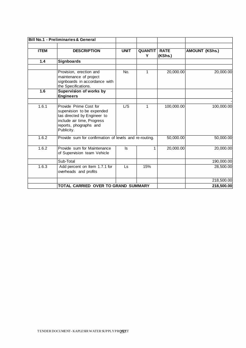
TENDER DOCUMENT- KAPLESIR WATER SUPPLY PROJECT 257
Bill No.1 - Preliminaries & General
ITEM DESCRIPTION UNIT QUANTIT
Y
RATE
(KShs.)
AMOUNT (KShs.)
1.4 Signboards
Provision, erection and
maintenance of project signboards in accordance with the Specifications.
No. 1 20,000.00 20,000.00
1.6 Supervision of works by
Engineers
-
-
1.6.1 Provide Prime Cost for supervision to be expended tas directed by Engineer to
include air time, Progress reports, phographs and Publicity.
L/S 1 100,000.00 100,000.00
1.6.2 Provide sum for confirmation of levels and re-routing. 50,000.00 50,000.00
1.6.2 Provide sum for Maintenance of Supervision team Vehicle
ls 1 20,000.00 20,000.00
Sub-Total 190,000.00
1.6.3 Add percent on Item 1.7.1 for
overheads and profits
Ls 15% 28,500.00
218,500.00
TOTAL CARRIED OVER TO GRAND SUMMARY 218,500.00
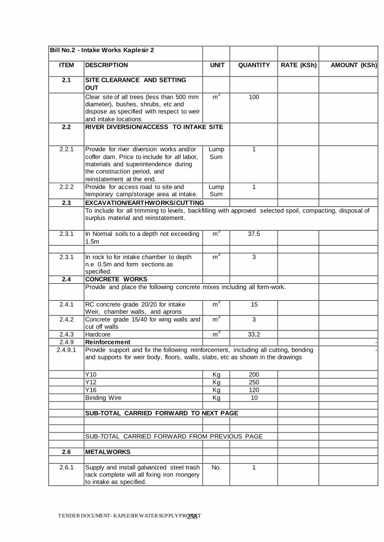
TENDER DOCUMENT- KAPLESIR WATER SUPPLY PROJECT 258
Bill No.2 - Intake Works Kaplesir 2
ITEM DESCRIPTION
UNIT QUANTITY RATE (KSh) AMOUNT (KSh)
2.1 SITE CLEARANCE AND SETTING
OUT
Clear site of all trees (less than 500 mm diameter), bushes, shrubs, etc and dispose as specified with respect to weir
and intake locations
m2
100
2.2 RIVER DIVERSION/ACCESS TO INTAKE SITE
2.2.1 Provide for river diversion works and/or
coffer dam. Price to include for all labor, materials and superintendence during the construction period, and
reinstatement at the end.
Lump
Sum
1
2.2.2 Provide for access road to site and temporary camp/storage area at intake.
Lump Sum
1
2.3 EXCAVATION/EARTHWORKS/CUTTING
To include for all trimming to levels, backfilling with approved selected spoil, compacting, disposal of surplus material and reinstatement.
2.3.1 In Normal soils to a depth not exceeding
1.5m
m3
37.5
2.3.1 In rock to for intake chamber to depth n.e 0.5m and form sections as specified.
m3
3
2.4 CONCRETE WORKS
Provide and place the following concrete mixes including all form-work.
2.4.1 RC concrete grade 20/20 for intake Weir, chamber walls, and aprons
m3
15
2.4.2 Concrete grade 15/40 for wing walls and cut off walls
m3
3
2.4.3 Hardcore m3
33.2
2.4.9 Reinforcement -
2.4.9.1 Provide support and fix the following reinforcement, including all cutting, bending and supports for weir body, floors, walls, slabs, etc as shown in the drawings
-
Y10 Kg 200
Y12 Kg 250
Y16 Kg 120
Binding Wire Kg 10
SUB-TOTAL CARRIED FORWARD TO NEXT PAGE
SUB-TOTAL CARRIED FORWARD FROM PREVIOUS PAGE
2.6 METALWORKS
2.6.1 Supply and install galvanized steel trash rack complete will all fixing iron mongery to intake as specified.
No. 1
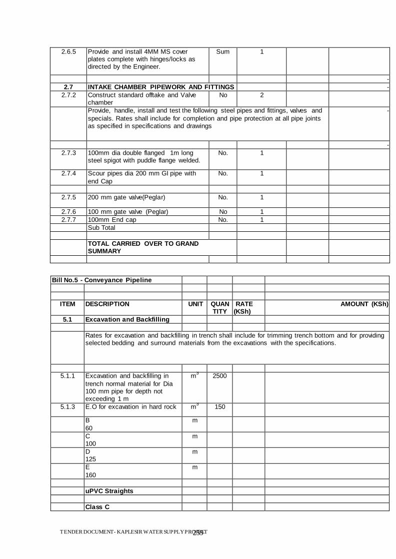
TENDER DOCUMENT- KAPLESIR WATER SUPPLY PROJECT 259
2.6.5 Provide and install 4MM MS cover plates complete with hinges/locks as directed by the Engineer.
Sum 1
-
2.7 INTAKE CHAMBER PIPEWORK AND FITTINGS -
2.7.2 Construct standard offtake and Valve chamber
No 2
Provide, handle, install and test the following steel pipes and fittings, valves and
specials. Rates shall include for completion and pipe protection at all pipe joints as specified in specifications and drawings
-
-
2.7.3 100mm dia double flanged 1m long steel spigot with puddle flange welded.
No. 1
2.7.4 Scour pipes dia 200 mm GI pipe with
end Cap
No. 1
2.7.5 200 mm gate valve(Peglar) No. 1
2.7.6 100 mm gate valve (Peglar) No 1
2.7.7 100mm End cap No. 1
Sub Total
TOTAL CARRIED OVER TO GRAND SUMMARY
Bill No.5 - Conveyance Pipeline
ITEM DESCRIPTION UNIT QUANTITY
RATE (KSh)
AMOUNT (KSh)
5.1 Excavation and Backfilling
Rates for excavation and backfilling in trench shall include for trimming trench bottom and for providing selected bedding and surround materials from the excavations with the specifications.
5.1.1 Excavation and backfilling in
trench normal material for Dia 100 mm pipe for depth not exceeding 1 m
m3
2500
5.1.3 E.O for excavation in hard rock m3
150
B
60
m
C 100
m
D 125
m
E
160
m
uPVC Straights
Class C
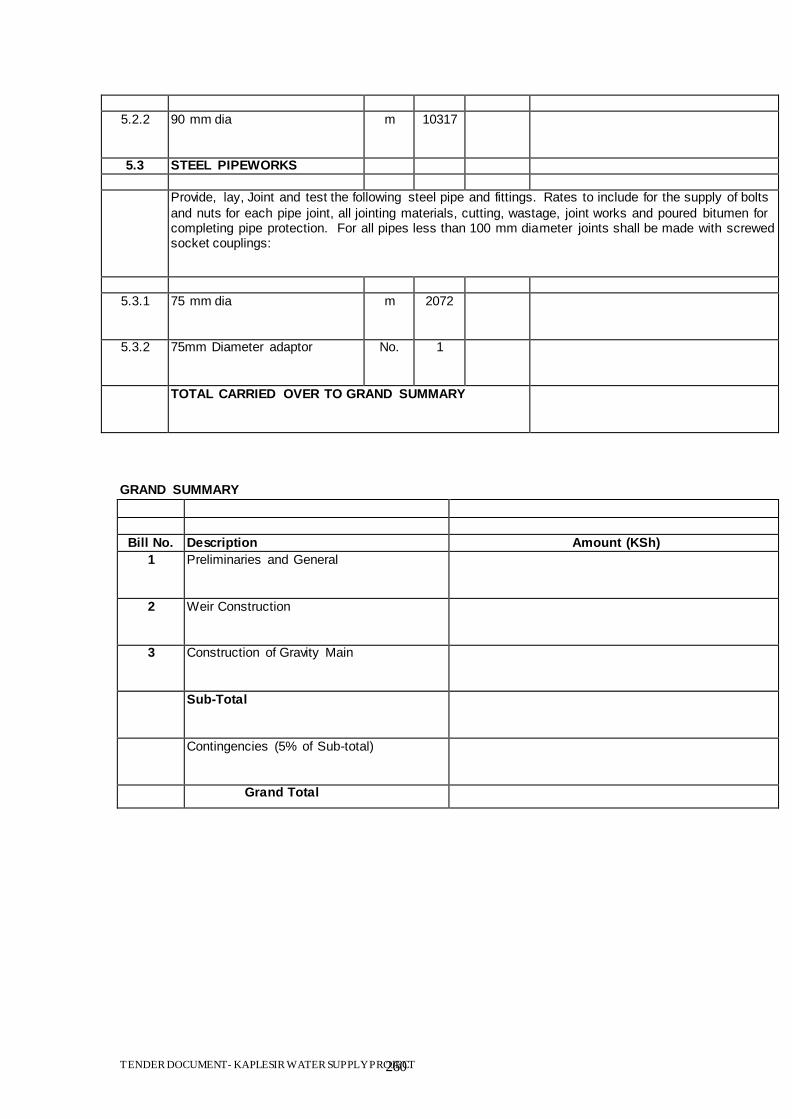
TENDER DOCUMENT- KAPLESIR WATER SUPPLY PROJECT 260
5.2.2 90 mm dia m 10317
5.3 STEEL PIPEWORKS
Provide, lay, Joint and test the following steel pipe and fittings. Rates to include for the supply of bolts
and nuts for each pipe joint, all jointing materials, cutting, wastage, joint works and poured bitumen for completing pipe protection. For all pipes less than 100 mm diameter joints shall be made with screwed socket couplings:
5.3.1 75 mm dia m 2072
5.3.2 75mm Diameter adaptor No. 1
TOTAL CARRIED OVER TO GRAND SUMMARY
GRAND SUMMARY
Bill No. Description Amount (KSh)
1 Preliminaries and General
2 Weir Construction
3 Construction of Gravity Main
Sub-Total
Contingencies (5% of Sub-total)
Grand Total

TENDER DOCUMENT- KAPLESIR WATER SUPPLY PROJECT 261
SECTION VII: DRAWINGS

TENDER DOCUMENT- KAPLESIR WATER SUPPLY PROJECT 262
SECTION IX: TENDER FORMS
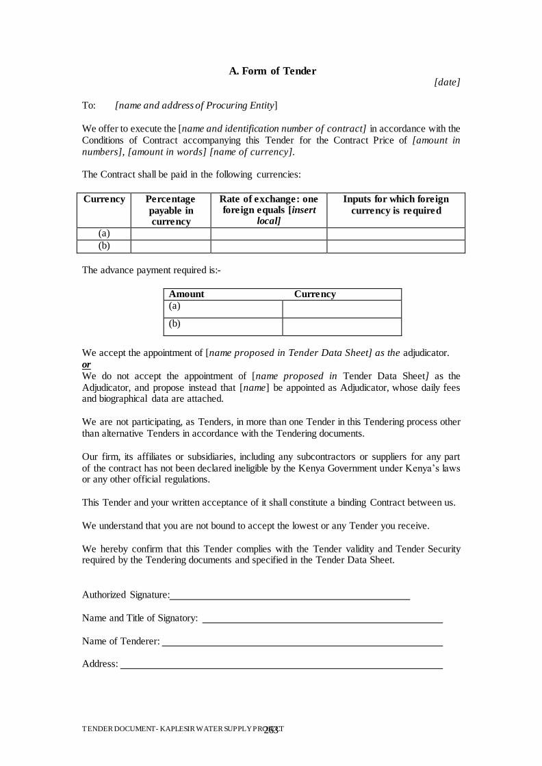
TENDER DOCUMENT- KAPLESIR WATER SUPPLY PROJECT 263
A. Form of Tender [date]
To: [name and address of Procuring Entity]
We offer to execute the [name and identification number of contract] in accordance with the Conditions of Contract accompanying this Tender for the Contract Price of [amount in numbers], [amount in words] [name of currency]. The Contract shall be paid in the following currencies:
Currency Percentage
payable in currency
Rate of exchange: one foreign equals [insert
local]
Inputs for which foreign
currency is required
(a)
(b)
The advance payment required is:-
Amount Currency (a)
(b)
We accept the appointment of [name proposed in Tender Data Sheet] as the adjudicator. or
We do not accept the appointment of [name proposed in Tender Data Sheet] as the Adjudicator, and propose instead that [name] be appointed as Adjudicator, whose daily fees and biographical data are attached. We are not participating, as Tenders, in more than one Tender in this Tendering process other than alternative Tenders in accordance with the Tendering documents. Our firm, its affiliates or subsidiaries, including any subcontractors or suppliers for any part of the contract has not been declared ineligible by the Kenya Government under Kenya‟s laws or any other official regulations. This Tender and your written acceptance of it shall constitute a binding Contract between us. We understand that you are not bound to accept the lowest or any Tender you receive. We hereby confirm that this Tender complies with the Tender validity and Tender Security required by the Tendering documents and specified in the Tender Data Sheet. Authorized Signature: Name and Title of Signatory: Name of Tenderer: Address:
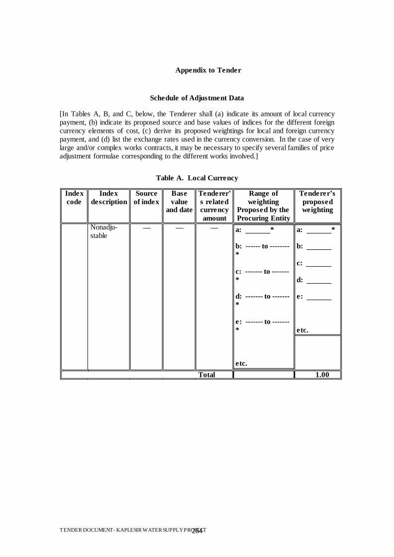
TENDER DOCUMENT- KAPLESIR WATER SUPPLY PROJECT 264
Appendix to Tender
Schedule of Adjustment Data [In Tables A, B, and C, below, the Tenderer shall (a) indicate its amount of local currency payment, (b) indicate its proposed source and base values of indices for the different foreign currency elements of cost, (c) derive its proposed weightings for local and foreign currency payment, and (d) list the exchange rates used in the currency conversion. In the case of very large and/or complex works contracts, it may be necessary to specify several families of price adjustment formulae corresponding to the different works involved.]
Table A. Local Currency
Index
code
Index
description
Source
of index
Base
value and date
Tenderer‘
s related currency
amount
Range of
weighting Proposed by the
Procuring Entity
Tenderer‘s
proposed weighting
Nonadju-stable
— — — a: *
b: ------ to --------
*
c: ------- to -------
*
d: ------- to -------
*
e: ------- to -------
*
etc.
a: *
b:
c:
d:
e:
etc.
Total 1.00
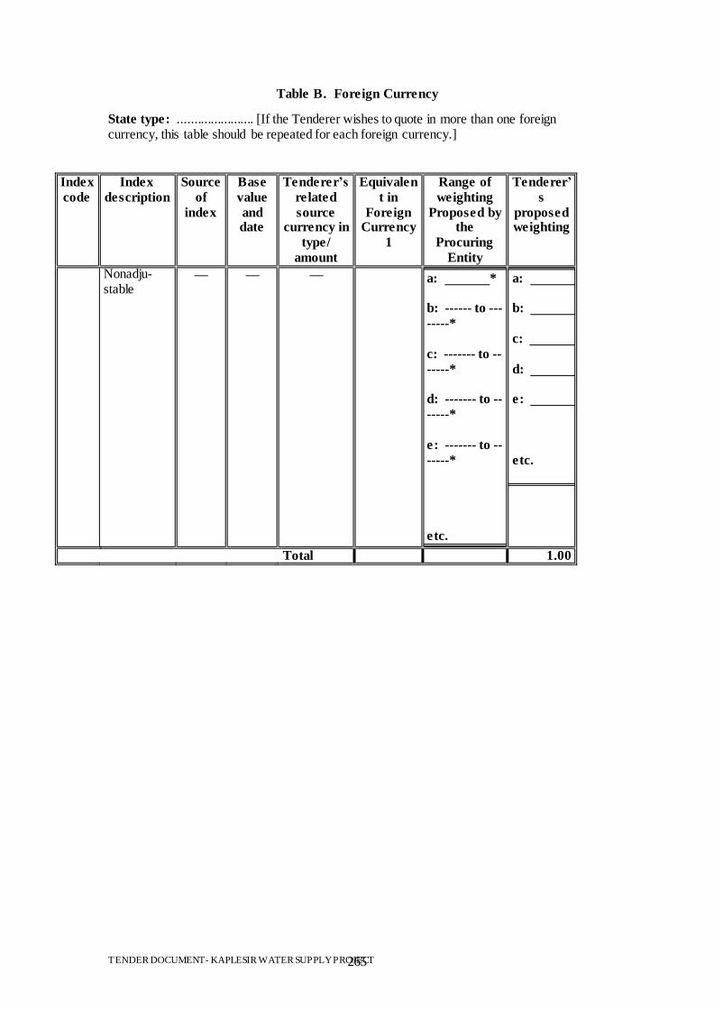
TENDER DOCUMENT- KAPLESIR WATER SUPPLY PROJECT 265
Table B. Foreign Currency
State type: ....................... [If the Tenderer wishes to quote in more than one foreign currency, this table should be repeated for each foreign currency.]
Index
code
Index
description
Source
of
index
Base
value
and date
Tenderer‘s
related
source currency in
type/
amount
Equivalen
t in
Foreign Currency
1
Range of
weighting
Proposed by the
Procuring
Entity
Tenderer‘
s
proposed weighting
Nonadju-stable
— — — a: *
b: ------ to ---
-----*
c: ------- to --
-----*
d: ------- to --
-----*
e: ------- to --
-----*
etc.
a: *
b:
c:
d:
e:
etc.
Total 1.00
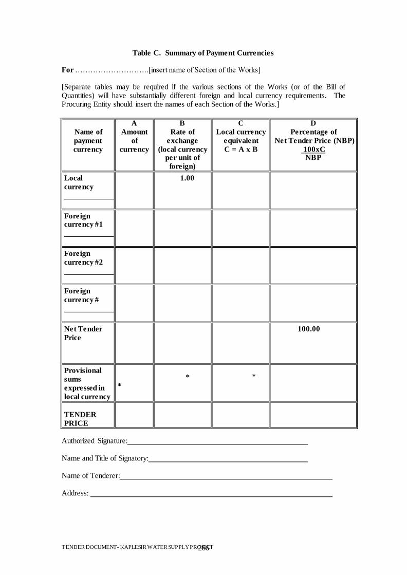
TENDER DOCUMENT- KAPLESIR WATER SUPPLY PROJECT 266
Table C. Summary of Payment Currencies For ………………………..[insert name of Section of the Works]
[Separate tables may be required if the various sections of the Works (or of the Bill of Quantities) will have substantially different foreign and local currency requirements. The Procuring Entity should insert the names of each Section of the Works.]
Name of
payment
currency
A
Amount
of
currency
B
Rate of
exchange
(local currency per unit of
foreign)
C
Local currency
equivalent
C = A x B
D
Percentage of
Net Tender Price (NBP)
100xC NBP
Local
currency
1.00
Foreign currency #1
Foreign
currency #2
Foreign
currency #
Net Tender
Price
100.00
Provisional
sums
expressed in
local currency
*
*
*
TENDER
PRICE
Authorized Signature: Name and Title of Signatory: Name of Tenderer: Address:
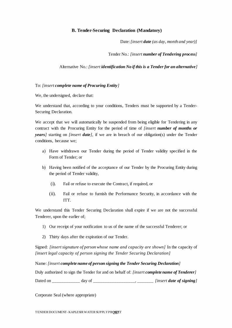
TENDER DOCUMENT- KAPLESIR WATER SUPPLY PROJECT 267
B. Tender-Securing Declaration (Mandatory)
Date: [insert date (as day, month and year)]
Tender No.: [insert number of Tendering process]
Alternative No.: [insert identification No if this is a Tender for an alternative]
To: [insert complete name of Procuring Entity]
We, the undersigned, declare that:
We understand that, according to your conditions, Tenders must be supported by a Tender-
Securing Declaration.
We accept that we will automatically be suspended from being eligible for Tendering in any
contract with the Procuring Entity for the period of time of [insert number of months or
years] starting on [insert date], if we are in breach of our obligation(s) under the Tender
conditions, because we;
a) Have withdrawn our Tender during the period of Tender validity specified in the
Form of Tender; or
b) Having been notified of the acceptance of our Tender by the Procuring Entity during
the period of Tender validity,
(i). Fail or refuse to execute the Contract, if required, or
(ii). Fail or refuse to furnish the Performance Security, in accordance with the
ITT.
We understand this Tender Securing Declaration shall expire if we are not the successful
Tenderer, upon the earlier of;
1) Our receipt of your notification to us of the name of the successful Tenderer; or
2) Thirty days after the expiration of our Tender.
Signed: [insert signature of person whose name and capacity are shown] In the capacity of
[insert legal capacity of person signing the Tender Securing Declaration]
Name: [insert complete name of person signing the Tender Securing Declaration]
Duly authorized to sign the Tender for and on behalf of: [insert complete name of Tenderer]
Dated on ____________ day of __________________, _______ [insert date of signing]
Corporate Seal (where appropriate)

TENDER DOCUMENT- KAPLESIR WATER SUPPLY PROJECT 268
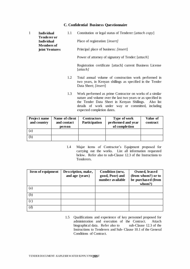
TENDER DOCUMENT- KAPLESIR WATER SUPPLY PROJECT 269
C. Confidential Business Questionnaire
1 Individual
Tenderer or
Individual
Members of
joint Ventures
1.1 Constitution or legal status of Tenderer: [attach copy] Place of registration: [insert] Principal place of business: [insert] Power of attorney of signatory of Tender: [attach] Registration certificate [attach] current Business License [attach]
1.2 Total annual volume of construction work performed in two years, in Kenyan shillings as specified in the Tender Data Sheet; [insert]
1.3 Work performed as prime Contractor on works of a similar nature and volume over the last two years or as specified in the Tender Data Sheet in Kenyan Shillings. Also list details of work under way or committed, including expected completion dates.
Project name
and country
Name of client
and contact
person
Contractors
Participation
Type of work
performed and year
of completion
Value of
contract
(a)
(b)
1.4 Major items of Contractor‟s Equipment proposed for
carrying out the works. List all information requested below. Refer also to sub-Clause 12.3 of the Instructions to Tenderers.
Item of equipment Description, make,
and age (years)
Condition (new,
good, Poor) and
number available
Owned, leased
(from whom?) or to
be purchased (from
whom?)
(a)
(b)
(c)
(d)
1.5 Qualifications and experience of key personnel proposed for
administration and execution of the Contract. Attach biographical data. Refer also to sub-Clause 12.3 of the Instructions to Tenderers and Sub- Clause 10.1 of the General Conditions of Contract.
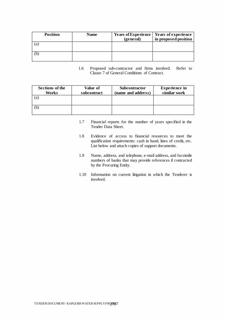
TENDER DOCUMENT- KAPLESIR WATER SUPPLY PROJECT 270
Position Name Years of Experience (general)
Years of experience in proposed position
(a)
(b)
1.6 Proposed sub-contractor and firms involved. Refer to
Clause 7 of General Conditions of Contract.
Sections of the
Works
Value of
subcontract
Subcontractor
(name and address)
Experience in
similar work (a)
(b)
1.7 Financial reports for the number of years specified in the
Tender Data Sheet.
1.8 Evidence of access to financial resources to meet the qualification requirements: cash in hand, lines of credit, etc. List below and attach copies of support documents.
1.9 Name, address, and telephone, e-mail address, and facsimile numbers of banks that may provide references if contracted by the Procuring Entity.
1.10 Information on current litigation in which the Tenderer is involved.
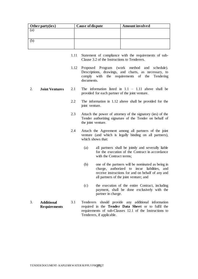
TENDER DOCUMENT- KAPLESIR WATER SUPPLY PROJECT 271
Other party(ies) Cause of dispute Amount involved (a)
(b)
1.11 Statement of compliance with the requirements of sub-
Clause 3.2 of the Instructions to Tenderers.
1.12 Proposed Program (work method and schedule). Descriptions, drawings, and charts, as necessary, to comply with the requirements of the Tendering documents.
2. Joint Ventures 2.1 The information listed in 1.1 – 1.11 above shall be provided for each partner of the joint venture.
2.2 The information in 1.12 above shall be provided for the joint venture.
2.3 Attach the power of attorney of the signatory (ies) of the Tender authorizing signature of the Tender on behalf of the joint venture.
2.4 Attach the Agreement among all partners of the joint venture (and which is legally binding on all partners), which shows that:
(a) all partners shall be jointly and severally liable for the execution of the Contract in accordance with the Contract terms;
(b) one of the partners will be nominated as being in
charge, authorized to incur liabilities, and receive instructions for and on behalf of any and all partners of the joint venture; and
(c) the execution of the entire Contract, including
payment, shall be done exclusively with the partner in charge.
3. Additional
Requirements
3.1 Tenderers should provide any additional information required in the Tender Data Sheet or to fulfil the requirements of sub-Clauses 12.1 of the Instructions to Tenderers, if applicable.
TENDER DOCUMENT- KAPLESIR WATER SUPPLY PROJECT 272
D. Integrity Declaration
UNDERTAKING BY TENDERER ON ANTI – BRIBERY POLICY / CODE OF
CONDUCT AND COMPLIANCE PROGRAMME
1. Each Tenderer must submit a statement, as part of the Tender documents, in either of the
two given formats which must be signed personally by the Chief Executive Officer or other appropriate senior corporate officer of the Tendering company and, where relevant, of its subsidiary in the Kenya. If a Tender is submitted by a subsidiary, a statement to this effect will also be required of the parent company, signed by its Chief Executive Officer or other appropriate senior corporate officer.
2. Tenderers will also be required to submit similar No-bribery commitments from their
subcontractors and consortium partners; the Tenderer may cover the subcontractors and consortium partners in its own statement, provided the Tenderer assumes full responsibility.
3.
a) Payment to agents and other third parties shall be limited to appropriate compensation for legitimate services.
b) Each Tenderer will make full disclosure in the Tender documentation of the
beneficiaries and amounts of all payments made, or intended to be made, to agents or other third parties (including political parties or electoral candidates) relating to the Tender and, if successful, the implementation of the contract.
c) The successful Tenderer will also make full disclosure [quarterly or semi-
annually] of all payments to agents and other third parties during the execution of the contract.
d) Within six months of the completion of the performance of the contract, the
successful Tenderer will formally certify that no bribes or other illicit commissions have been paid. The final accounting shall include brief details of the goods and services provided that they are sufficient to establish the legitimacy of the payments made.
e) Statements required according to subparagraphs (b) and (d) of this paragraph will
have to be certified by the company's Chief Executive Officer, or other appropriate senior corporate officer.
4. Tenders which do not conform to these requirements shall not be considered.
5. If the successful Tenderer fails to comply with its No-bribery commitment, significant
sanctions will apply. The sanctions may include all or any of the following:
a) Cancellation of the contract; b) Liability for damages to the public authority and/or the unsuccessful competitors
in the Tendering possibly in the form of a lump sum representing a pre-set percentage of the contract value (liquidated).
6. Tenderers shall make available, as part of their Tender, copies of their anti-Bribery
Policy/Code of Conduct, if any, and of their-general or project - specific - Compliance Program.
TENDER DOCUMENT- KAPLESIR WATER SUPPLY PROJECT 273
7. The Government of Kenya has made special arrangements for adequate oversight of the
procurement process and the execution of the contract, and has invited civil society and other competent Government Departments to participate in the oversight. Those charged with the oversight responsibility will have full access to all documentation submitted by Tenderers for this contract, and to which in turn all Tenderers and other parties involved or affected by the project shall have full access (provided, however, that no proprietary information concerning a Tenderer may be disclosed to another Tenderer or to the public).
TENDER DOCUMENT- KAPLESIR WATER SUPPLY PROJECT 274
ANTI-CORRUPTION DECLARATION COMITMENT/ PLEDGE (Sections39, 40,41,42,43 & of the PPD Act, 2005) I/We/Messrs……………………………………………………………………………. of Street, Building, P O Box…………………………………………………………… ………………………………………………………………………………………….. Contact/Phone/E mail………………………………………………………………….. declare that Public Procurement is based on a free and fair competitive Tendering process which should not be open to abuse. I/We ..………………………………………………………………………………….. declare that I/We will not offer or facilitate, directly or indirectly, any inducement or reward to any public officer, their relations or business associates, in connection with Tender/Tender No ………………………..………………………………………………. for or in the subsequent performance of the contract if I/We am/are successful. Authorized Signature................................................................................................ Name and Title of Signatory……………………………………………………………

TENDER DOCUMENT- KAPLESIR WATER SUPPLY PROJECT 275
E. Letter of Acceptance
[Letter head paper of the Procuring Entity]
[date]
To: [name and address of the Contractor] This is to notify you that your Tender dated [date] for execution of the [name of the Contract and identification number, as given in the Contract Data Sheet] for the Contract Price of the equivalent of [amount in numbers and works] [name of currency], as corrected and modified in accordance with the Instructions to Tenderers is hereby accepted by us. We confirm that [insert name proposed by the procuring entity] to be the Adjudicator. We accept that [name proposed by Tenderer] be appointed as Adjudicator.
Or
We do not accept that [name proposed by Tenderer] be appointed as adjudicator, and by sending a copy of this letter of acceptance to [insert the name of the Appointing Authority], we are hereby requesting [name], the Appointing Authority, to appoint the adjudicator in accordance with Clause 44.1 of the Instructions to Tenderers.
You are hereby instructed to proceed with the execution of the said works in accordance with the Contract documents. Please return the contract dully signed.
Authorized Signature:
Name and Title of Signatory: Name of Agency: Attachment: Form of Contract

TENDER DOCUMENT- KAPLESIR WATER SUPPLY PROJECT 276
F. Form of Contract Agreement
This Agreement, made the [day] day of [month], [year] between [name and address of Procuring Entity] (hereinafter called “the Procuring Entity”) and [name and address of Contractor] (hereinafter called “the Contractor”) of the other part. Whereas the Procuring Entity is desirous that the Contractor execute [name and identification number of contract] (hereinafter called “the Works”) with the objectives of [insert functional objectives of the works] and the Procuring Entity has accepted the Tender by the Contractor for the execution and completion of such works and the remedying of any defects therein in the sum of [contract price in words and figures] (hereinafter called “Contract Price”).
NOW THIS AGREEMENT WITNESSES AS FOLLOWS: 1. In this Agreement, words and expressions shall have the same meanings as are
respectively assigned to them in the Conditions of Contract hereinafter referred to, and they shall be deemed to form and be read and construed as pert of this Agreement;
2. In consideration of the payments to be made by the Procuring Entity to the Contractor
as hereinafter mentioned, the Contractor hereby covenants with the Procuring Entity to execute and complete the Works and remedy any defects therein in conformity in all respects with the provisions of the Contract;
3. The Procuring Entity hereby covenants to pay the Contractor in consideration of the
execution and completion of the Works and the remedying of defects wherein the Contract Price or such other sum as may become payable under the provisions of the Contract at the times and in the manner prescribed by the Contract.
In Witness whereof the parties thereto have caused this Agreement to be executed the day and year first before written. The Common Seal of Was hereunto affixed in the presence of: Signed, Sealed, and Delivered by the said In the presence of: Tendering Signature of Procuring Entity Binding Signature of Contractor

TENDER DOCUMENT- KAPLESIR WATER SUPPLY PROJECT 277
SECTION X: FORMS OF SECURITY
278
A. Tender Security (Bank or Insurance Guarantee)
(Optional)
[If required, the Bank or Insurance Company/Tenderer shall fill in this Guarantee form in
accordance with the instructions indicated in brackets.]
[insert bank’s or insurance company’s name, and address of issuing branch or office]
Beneficiary: [insert name and address of Procuring Entity]
Date: [insert date]
TENDER GUARANTEE No.:[insert number]
We have been informed that [insert name of the Tenderer; if a joint venture, list complete
legal names of partners] (hereinafter called "the Tenderer") has submitted to you its Tender
dated [insert date] (hereinafter called "the Tender") for the execution of [insert name of
Contract] under Invitation for Tenders No. [insert IFT number] (“the IFT”).
Furthermore, we understand that, according to your conditions, Tenders must be supported by
a Tender Guarantee.
At the request of the Tenderer, we [insert name of bank or insurance company] hereby
irrevocably undertake to pay you any sum or sums not exceeding in total an amount of [insert
amount in figures expressed in the currency of the Purchaser’s Country or the equivalent
amount in an international freely convertible currency] ([insert amount in words]) upon
receipt by us of your first demand in writing accompanied by a written statement stating that
the Tenderer is in breach of its obligation(s) under the Tender conditions, because the
Tenderer;
a) Has withdrawn its Tender during the period of Tender validity specified by
the Tenderer in the Form of Tender; or
b) Does not accept the correction of errors in accordance with the Instructions to
Tenderers (hereinafter “the ITT”) of the IFT; or
c) Having been notified of the acceptance of its Tender by the Procuring Entity
during the period of Tender validity;
(i). Fails or refuses to execute the Contract Form, if required, or
(ii). Fails or refuses to furnish the Performance Security, in accordance
with the ITT.
This Guarantee shall expire;
a) If the Tenderer is the successful Tenderer, upon our receipt of copies of the
Contract signed by the Tenderer and of the Performance Security issued to
you by the Tenderer; or
b) If the Tenderer is not the successful Tenderer, upon the earlier of;

279
(i) Our receipt of a copy of your notification to the Tenderer that the
Tenderer was unsuccessful, or
(ii) Thirty days after the expiration of the Tenderer‟s Tender.
Consequently, any demand for payment under this Guarantee must be received by us at the
office on or before that date.
_____________________________ [signature(s) of authorized representative(s) ]
280
B. Performance Bank or Insurance Guarantee [Unconditional]
[The Bank or Insurance Company/successful Tenderer providing the Guarantee shall fill
in this form in accordance with the instructions indicated in brackets, if the Procuring Entity
requires this type of security.]
[insert bank’s or insurance company’s name, and address of issuing branch or office]
Beneficiary: [insert name and address of Procuring Entity]
Date: [insert date]
PERFORMANCE GUARANTEE No.: [insert Performance Guarantee number]
We have been informed that [insert name of Contractor] (hereinafter called "the Contractor")
has entered into Contract No. [insert reference number of the Contract] dated with you, for
the execution of [insert name of Contract and brief description of Works] (hereinafter called
"the Contract").
Furthermore, we understand that, according to the conditions of the Contract, a Performance
Guarantee is required.
At the request of the Contractor, we [insert name of Bank or Insurance Company] hereby
irrevocably undertake to pay you any sum or sums not exceeding in total an amount of [insert
amount in figures] ([insert amount in words]), such sum being payable in the types and
proportions of currencies in which the Contract Price is payable, upon receipt by us of your
first demand in writing accompanied by a written statement stating that the Contractor is in
breach of its obligation(s) under the Contract, without your needing to prove or to show
grounds for your demand or the sum specified therein.
We hereby waive the necessity of your demanding the said debt from the Contractor before
presenting us with the demand.
We further agree that no change, addition or other modification of the terms of the Contract or
of the Works to be performed there under or of any of the Contract documents which may be
made between you and the Contractor shall in any way release us from any liability under this
Guarantee, and we hereby waive notice of any change, addition, or modification.
This guarantee shall expirenot later than thirty days from the date of issuance of the Taking-
Over Certificate.
[signature(s) of an authorized representative(s) of the Bank or Insurance Company]
281
C. Bank or Insurance Guarantee for Advance Payment
[Bank’s or Insurance Company’s Name and Address of Issuing Branch or Office]
Beneficiary: ___________________ [Name and Address of Procuring
Entity]
Date: ________________
ADVANCE PAYMENT GUARANTEE No.: _________________
We have been informed that [name of Contractor] (hereinafter called "the Contractor") has
entered into Contract No. [reference number of the contract] dated ______ with you, for the
execution of [name of contract and brief description of Works] (hereinafter called "the
Contract").
Furthermore, we understand that, according to the conditions of the Contract, an advance
payment in the sum [amount in figures] ( ) [amount in words] is to be made against an
advance payment guarantee.
At the request of the Contractor, we [name of Bank or Insurance Company] hereby
irrevocably undertake to pay you any sum or sums not exceeding in total an amount of
[amount in figures] ( ) [amount in words] upon receipt by us of your first demand
in writing accompanied by a written statement stating that the Contractor is in breach of its
obligation under the Contract because the Contractor used the advance payment for purposes
other than the costs of mobilization in respect of the Works.
We further agree that no change or addition to or other modification of the terms of the
Contract or of the Works to be performed thereunder or of any of the Contract documents
which may be made between ________________________[name of Procuring Entity] and
the Contractor, shall in any way release us from any liability under this guarantee, and we
hereby waive notice of any such change, addition or modification.
No drawing may be made by you under this guarantee until we have received notice in
writing from you that an advance payment of the amount listed above has been paid to the
Contractor pursuant to the Contract.
The maximum amount of this guarantee shall be progressively reduced by the amount of the
advance payment repaid by the Contractor as indicated in copies of interim statements or
payment certificates which shall be presented to us. This guarantee shall expire, at the latest,
upon our receipt of a copy of the interim payment certificate indicating that eighty (80)
percent of the Contract Price has been certified for payment, or on the ___ day of _____,
2___, whichever is earlier. Consequently, any demand for payment under this guarantee must
be received by us at this office on or before that date.

282
Yours truly,
Signature and seal:
Name of Bank or Insurance Company:
Address:
Date:

283
SECTION XI: APPLICATION TO PUBLIC PROCUREMENT
ADMINISTRATIVE REVIEW BOARD

284
FORM RB 1
REPUBLIC OF KENYA
PUBLIC PROCUREMENT ADMINISTRATIVE REVIEW BOARD
APPLICATION NO…………….OF……….….20……...
BETWEEN
……………………………………………………….APPLICANT
AND
…………………………………RESPONDENT (Procuring Entity)
Request for review of the decision of the…………… (Name of the Procuring Entity) of
……………dated the…day of ………….20……….in the matter of Tender No………..…of
…………..20…
REQUEST FOR REVIEW
I/We……………………………,the above named Applicant(s), of address: Physical
address…………….Fax No……Tel. No……..Email ……………, hereby request the Public
Procurement Administrative Review Board to review the whole/part of the above mentioned
decision on the following grounds , namely:-
1.
2.
etc.
By this memorandum, the Applicant requests the Board for an order/orders that: -
1.
2.
etc
SIGNED ………………. (Applicant)
Dated on…………….day of ……………/…20…
FOR OFFICIAL USE ONLY
Lodged with the Secretary Public Procurement Administrative Review Board on …………
day of ………....20….………
SIGNED
Board Secretary

285