standard technical specifications for roadway and … technical specifications for roadway and...
TRANSCRIPT

1
PINELLAS COUNTY
DEPARTMENT OF ENVIRONMENT AND
INFRASTRUCTURE (DEI)
Standard Technical Specifications
for Roadway and Related Construction
(Revised October 2011 )

2
TABLE OF CONTENTS
MEASUREMENT AND PAYMENT & ABBREVIATIONS AND
DEFINITIONS ..................................................................................... 4
005-0700 SURVEY AND LAYOUT BY CONTRACTOR .......................................... 5
005-0800 QUANTITY MEASUREMENTS SURVEY BY CONTRACTOR ................. 6
005-0850 PERMITTING AS-BUILT SURVEY BY CONTRACTOR ........................... 7
005-0900 AS-BUILT SURVEY (UTILITY) BY CONTRACTOR ................................. 8
101-0100 MOBILIZATION ..................................................................................... 9
102-0100 MAINTENANCE OF TRAFFIC ............................................................ 10
102-201 MAINTENANCE OF TRAFFIC – RAILROAD ....................................... 12
102-5000 WATER FOR DUST CONTROL ........................................................... 14
104 PREVENTION, CONTROL AND ABATEMENT OF EROSION AND WATER POLLUTION ............................................................... 15
110 CLEARING AND GRUBBING .............................................................. 18
110-2001 ROOT CONTROL BARRIER ................................................................ 20
120 EXCAVATION AND EMBANKMENT ................................................... 21
120-0513 LOAD, HAUL & DISPOSAL OF CONTAMINATED SOIL…………...24
120-1100 GRADING ............................................................................................ 25
120-1200 DREDGING .......................................................................................... 26
121 FLOWABLE CONCRETE FILL ............................................................ 27
125-3000 BEDDING MATERIAL .......................................................................... 28
160 STABILIZATION - Type B ................................................................... 29
162-1000 ORGANIC TOPSOIL ............................................................................ 30
200 ROADWAY BASE - Limerock .............................................................. 31
204 ROADWAY BASE - Recycled Crushed Conc./Graded Aggregate ..... 32
234 SUPERPAVE ASPHALT BASE ........................................................... 34
285 OPTIONAL BASE COURSES .............................................................. 36
334 SUPERPAVE ASPHALT CONCRETE .................................................. 38
337 ASPHALTIC CONCRETE FRICTION COURSE - FDOT Types FC-2, FC-3, FC - 5, and FC-6 .................................... 42
350-0200 PAVEMENT - Cement Concrete, Driveways ....................................... 43
350-201 CONCRETE - Warning Strip ................................................................ 44
353 DRIVEWAY RESTORATION - In Kind ................................................. 45
380 MILLING AND RESURFACING OF EXISTING ASPHALTIC CONCRETE PAVEMENT AND ROADWAY BASE ........................... 46
400 CONCRETE STRUCTURES ................................................................ 49
410 BOX CULVERT SECTIONS - Concrete, Pre-cast ................................ 50
415 REINFORCING STEEL ........................................................................ 52
425 INLETS, MANHOLES AND JUNCTION BOXES - FDOT and PCED Type Structures .................................................. 53
425-9220 SKIMMER FOR OUTFALL DRAINAGE STRUCTURE ......................... 55
430 PIPE CULVERT ................................................................................... 56
430-4000 JACK AND BORE ................................................................................ 58
430-5000 U-TYPE ENDWALLS AND FLARED OR MITERED END SECTIONS... 60

3
440-1000 UNDERDRAIN - Polyvinyl-Chloride(PVC), Roadway .......................... 61
450-451 MISCELLANEOUS STRUCTURAL CONSTRUCTION……………….62
455 SHEET PILING - Hydraulic Press………………………………………..64
470 TIMBER STRUCTURES ....................................................................... 66
470-1600 BOARDWALKS ................................................................................... 69
470-4001 TIMBER PILINGS ................................................................................ 71
515 HANDRAIL - Pipe ................................................................................ 72
520 CURB AND GUTTER & TRAFFIC SEPARATORS .............................. 73
521 BARRIER WALL - Concrete ................................................................ 74
522 SIDEWALK - Concrete ........................................................................ 75
524 DITCH PAVEMENT - Concrete ............................................................ 77
530-1000 RIPRAP - Sand - Cement .................................................................... 78
530-2000 RIPRAP - Rubble ................................................................................. 79
530-3000 GABIONS ............................................................................................ 80
536 GUARDRAIL - Metal............................................................................ 85
550 FENCING - FDOT Type B ................................................................... 86
555 DIRECTIONAL BORE .......................................................................... 87
575 SODDING ............................................................................................ 88
630 to 699 TRAFFIC SIGNALS ............................................................................. 89
700 HIGHWAY SIGNING ............................................................................ 92
706 to 710 PAVEMENT STRIPING, MARKINGS AND REFLECTIVE PAVEMENT MARKERS ................................................................... 93
715 STREET LIGHTING CONDUIT SYSTEM.............................................. 94
780 INTELLIGENT TRANSPORTATION SYSTEM (ITS)………………....95
781 DYNAMIC MESSAGE SIGNS (DMS)……………………………………97
782 ITS VIDEO EQUIPMENT………………………………………………….102
783 INTELLIGENT TRANS. SYSTEM – Optic Cable and Interconnect….105
784 INTELLIGENT TRANSPORTATION SYSTEMS –Network Devices..123
785 ITS INFRASTRUCTURE…………………………………………………..124
786 VEHICLE DETECTION & DATA COLLECTION……………………….129
800-2100 SHEETING AND BRACING………………………………………………..132
800-9001 BARRICADE - PCED Type III……………………………………………..133
800-9010 REFLECTORS - FDOT Cases I and II …………………………………...134
900-0200 OFFICE FOR THE ENGINEER ………………………………………….…135
900-0201 OFFICE FOR THE ENGINEER (LARGER)…………………………….….138
900-0300 POND CLAY LINER………………………………………………………...141
900-1060 COFFERDAMS ……………………………………………………………..142
999-0000 UNSPECIFIED WORK (ALLOWANCE)…………………………………...143
999-0003 SURVEY WORK (ALLOWANCE)……………………………………….…144

4
SPECIFICATIONS FOR ROADWAY AND
RELATED CONSTRUCTION
1-0100
Measurement and Payment
The items of work and the pay item numbers specified in the Schedule of Values contained in the Proposal are identified specifically with the corresponding primary Section numbers of the Technical Specifications, and are hereby incorporated by reference as extensions of the corresponding Technical Specifications. The pay item descriptions shown in the Specifications, as, for example, Asphaltic Concrete or Concrete, Class II, shall be deemed to include all additional descriptive wording shown on the Plans or in the Schedule of Values for the respective pay items. The contract price shown for the various pay items in the Schedule of Values contained in the Proposal upon which award of the Contract is based shall constitute full compensation for all work and materials described and specified in the Specifications for the respective pay items.
Pay items in the bid submittal sheets of a contract shall be constructed in accordance with the Pinellas County Department of Environment and Infrastructure Standard Technical Specifications for Roadway and Related Construction (PCDEI Std. Tech. Spec.), contained herein, as amended by technical special provisions or supplemental specifications in the construction contract.
The first three digits of the pay item number and the pay item description shall be used to determine the applicable specification in the PCDEI Std. Tech. Spec. If there is no applicable specification within these PCDEI St. Tech. Spec., as amended by technical special provisions or supplemental specifications in the construction contract, then the pay item shall be constructed in accordance with the applicable section of the FDOT Specifications. In such instance, the first three digits of the pay item number and the pay item description shall be used to determine the applicable section in the FDOT Specifications.
De-watering testing requirements – If there is no separate pay item for de-watering, then the cost for de-watering shall be included in the pay items where de-watering is required. The Contractor will monitor the de-watering discharge to ensure that turbidity levels remain under the State allowed level of 29 NTU's above background. If turbidity levels exceed these State standards, activities will cease and corrective measures will be implemented until the discharge is in compliance. The Contractor shall make every effort to contain the discharge within County owned drainage. Should the Contractor choose to de-water to waters of the State, the Contractor must meet the testing requirements of 62-621.300(2) or 62-621.300(1), including water quality testing. For all pay items where de-watering is required, said pay items shall include the testing, reporting, and notification requirements described in the "State of Florida - Department of Environmental Protection - Generic Permit for Discharge of Produced Ground Water From Any Non-contaminated Site Activity" [62-621.300(2)] or "State of Florida - Department of Environmental Protection - Generic Permit for Discharges from Petroleum Contaminated Sites" [62-621.300(1)]. Payment for sheeting and bracing shall be included in the applicable pay item where sheeting and bracing is required for construction, unless otherwise provided for in the contract.
Abbreviations and Definitions
FDOT – The Florida Department of Transportation. ID – Inside diameter, or dimension.
PCED – The Pinellas County Engineering and Technical Support Division.
DEI – The Pinellas County Department of Environment and Infrastructure
Schedule of Values – The Schedule of Values contained in the Proposal
Ton – A weight of two thousand (2000) pounds.
FDOT Specifications – FDOT Standard Specifications for Road and Bridge Construction (latest edition)
(including latest FDOT approved interim specifications)
FDOT Design Standards - FDOT Design Standards for Design, Construction, Maintenance and Utility
Operations on the State Highway System (latest edition) (including latest FDOT approved interim details)

5
SURVEY AND LAYOUT BY CONTRACTOR
005-0700
The work specified under this Section consists of all materials and labor necessary to complete the survey
and layout by the Contractor, in accordance with the section “SURVEY AND LAYOUT” of contract specifications, to completely construct the project, to the satisfaction of the Engineer.
This work shall include providing all lines, grades, boundaries and required survey and/or layout necessary to construct and inspect the project. All right-of-way and easement boundaries and centerline control points shall be established and maintained through the contract period by the Contractor.
The Contractor shall employ or retain the services of a Florida registered Professional Land Surveyor to satisfy all the requirements specified in section “SURVEY AND LAYOUT” of contract specifications.
The Contractor shall be responsible to perform all layouts in acceptable standard methods.
The Contractor shall thoroughly familiarize themselves with the plans, specifications and on-site field conditions to submit a lump sum bid that will include all means and methods necessary to satisfy the survey and layout requirements of this project. All field books and calculations, related to layout, shall be available to the engineer upon request, for a period of one year after construction completion.
STATION BOARDS: Where applicable, contractor shall furnish and install 1 x4 station boards,
painted with white enamel paint with black enamel paint numbering, every 100-feet at the
Right of Way for the entire project length and/or project limits. Contractor shall maintain for
the duration of the project.
RECORD DRAWINGS: Record Drawings are a set of signed/sealed CONTRACT
DRAWINGS that are maintained by the Contractor for the express use of recording AS-BUILT
INFORMATION. Record Drawings will be verified by the ENGINEER at each monthly pay
estimate request prior to processing payment request. At Final Acceptance, Contractor will
provide one original Record Drawing set (in color) and eight (8) additional color copies to the
ENGINEER.
Basis of Payment:
The pay quantity shall consist of all materials and labor necessary to complete the survey and layout by the Contractor in connection with the construction of the project, performed to the satisfaction of the Engineer. The pay quantity for the work specified under this Section shall be one Lump Sum quantity.

6
QUANTITY MEASUREMENTS SURVEY BY CONTRACTOR
005-0800
The work specified under this Section consists of all materials and labor necessary to complete all quantity measurements by the Contractor, to the satisfaction of the Engineer.
The Contractor shall employ or retain the services of a Florida registered Professional Land Surveyor to satisfy all the requirements related to quantity measurements.
The Contractor shall be responsible to perform all measurements in acceptable standard methods.
The Contractor shall thoroughly familiarize themselves with the plans, specifications and on-site field conditions to submit a lump sum bid that will include all means and methods necessary to satisfy the measurement requirements of this project.
The Contractor shall provide summaries to the County, signed and sealed by a Florida registered Professional Land Surveyor, listing all items measured, measurement quantities and dates of measurements, within 5 days after receiving written request from the County.
For validation of earthwork volumes specified under Section 120 Excavation and Embankment, the Contractor shall provide the following:
a. Collect a sufficient number of data points to accurately represent the following surfaces:
i. Pre-excavation Surface after clearing and grubbing. ii. Final Surface.
b. Compute earthwork volumes using the average end area method. c. Provide Earthwork volume in a report format signed and sealed by a
Florida registered Professional Land Surveyor. d. Deliverables will include:
i. Digital data files of all surface data points in a standard ASCII format.
ii. Digital Terrain Model (DTM) files. e. All Survey activities and deliverables are to be in accordance with:
i. PINELLAS COUNTY CADD MANUAL FOR LAND SURVEYING AND CIVIL ENGINEERING
ii. Rule 5J-17.050 through 5J-17.052 Florida Administrative Code, and Chapter 472 Florida Statutes.
NOTE: The PINELLAS COUNTY CADD MANUAL FOR LAND SURVEYING AND CIVIL ENGINEERING can be found on the Pinellas County Department of Environment and Infrastructure (DEI) website.
In the case of dispute in quantity measurements, the County reserves the right to have Pinellas County DEI Survey Section verify all measurements and calculations. Contractor’s Surveyor shall make all field books and calculations available for review by the engineer or his designee.
Basis of Payment:
The pay quantity shall consist of all materials and labor necessary to complete the quantity measurements by the Contractor in connection with the construction of the project, performed to the satisfaction of the Engineer. The pay quantity for the work specified under this Section shall be one Lump Sum quantity.
7
PERMITTING AS-BUILT SURVEY REQUIREMENTS
BY CONTRACTOR 005-0850
The work specified under this Section consists of all materials and labor necessary to complete all required
permitting as-built requirements, to the satisfaction of the Engineer.
The Contractor shall employ or retain the services of a Florida registered Professional Land Surveyor to satisfy all the requirements related to this as-built survey.
The Contractor shall be responsible to perform all survey operations in acceptable standard methods.
The Contractor shall thoroughly familiarize themselves with the plans, specifications and on-site field conditions to submit a lump sum bid that will include all means and methods necessary to satisfy the permitting as-built requirements of this project.
The Contractor shall provide the as-built survey to the County, signed and sealed by a Florida registered Professional Land Surveyor, within 25 days after receiving written request from the County. Contractor’s Surveyor shall make all field books and calculations available for review by the engineer or his designee.
The items that require as-built surveying shall include:
Control structures - weir and grate elevations
Control structures - weir and grate dimensions
Ponds - top of bank, toe of slope, etc.
Other items (if specified in Technical Special Provisions)
All items highlighted on marked-up plans, or defined by other means, provided by the Engineer of Record, shall be as-built and certified by a Florida registered Professional Land Surveyor.
DELIVERABLES
All Survey activities and deliverables are to be in accordance with the PINELLAS COUNTY CADD MANUAL FOR LAND SURVEYING AND CIVIL ENGINEERING (formerly known as PINELLAS COUNTY GUIDE FOR PROFESSIONAL SURVEY AND MAPPING SERVICES), and Rule 5J-17.050 through 5J-17.052 Florida Administrative Code, and Chapter 472 Florida Statutes and shall include ten (10) Signed and Sealed As-built Surveys, (5J-17.052). Deliverables will also include all Autodesk Civil 3D (latest edition) project files; fieldbook files; digital data files of all surveyed points in the standard ASCII format; and an electronic copy of the signed and seal survey in ADOBE (.pdf) format
The PINELLAS COUNTY CADD MANUAL FOR LAND SURVEYING AND CIVIL ENGINEERING can be found on the Pinellas County Department of Environment and Infrastructure (DEI) website.
Basis of Payment:
The pay quantity shall consist of all materials and labor necessary to complete the permitting as-built survey requirements by the Contractor in connection with the construction of the project, performed to the satisfaction of the Engineer. The pay quantity for the work specified under this Section shall be one Lump Sum quantity.

8
AS-BUILT SURVEY REQUIREMENTS (UTILITY)
BY CONTRACTOR 005-0900
The work specified under this Section consists of all materials and labor necessary to complete all
required as-built survey requirements for Pinellas County Utility facilities and appurtenances specifically listed in these specifications, to the satisfaction of the Engineer.
The Contractor shall employ or retain the services of a Florida registered Professional Land Surveyor to satisfy all the requirements related to this as-built survey.
The Contractor shall be responsible to perform all survey operations in acceptable standard methods.
The Contractor shall thoroughly familiarize themselves with the plans, specifications and on-site field conditions to submit bid that will include all means and methods necessary to satisfy the utility as-built requirements of this project.
The Contractor shall provide the utility as-built survey to the County, signed and sealed by a Florida registered Professional Land Surveyor, within 30 days after receiving written or verbal request from the Engineer. Contractor’s Surveyor shall make all field books and calculations available for review by the Engineer or his designee. Contractor shall refer to the Utility Company’s Specifications for items that require as-built surveying. DELIVERABLES All Survey activities and deliverables are to be in accordance with the PINELLAS COUNTY CADD MANUAL FOR LAND SURVEYING AND CIVIL ENGINEERING (formerly known as PINELLAS COUNTY GUIDE FOR PROFESSIONAL SURVEY AND MAPPING SERVICES), and Rule 5J-17.050 through 5J-17.052 Florida Administrative Code, and Chapter 472 Florida Statutes and shall include ten (10) Signed and Sealed As-built Surveys, (5J-17.052). Deliverables will also include all Autodesk Civil 3D (latest edition) project files; fieldbook files; digital data files of all surveyed points in the standard ASCII format; and an electronic copy of the signed and seal survey in ADOBE (.pdf) format. The PINELLAS COUNTY CADD MANUAL FOR LAND SURVEYING AND CIVIL ENGINEERING can be found on the Pinellas County Department of Environment and Infrastructure (DEI) website.
Basis of Payment:
The pay quantity shall consist of all materials and labor necessary to complete the utility as-built survey requirements by the Contractor in connection with the construction of the project, performed to the satisfaction of the Engineer. The pay quantity for the work specified under this Section shall be one Lump Sum quantity.

9
MOBILIZATION 101-0100
The work specified under this Section consists of the preparatory work and operations in mobilizing to begin work on the project, including but not limited to those operations necessary for the movement of personnel, equipment, supplies and incidentals to the project site(s), and for the establishment of temporary offices, buildings, safety equipment and first aid supplies, sanitary and other facilities as required by these specifications, special provisions, and state and local laws and regulations.
The Contractor shall furnish, install, and maintain station boards (every 100 ft) on one side of the project for the duration of the project. The station boards shall be 48 inch long, 1” x 4” lumber, painted white with 3 inch black stenciled numbers. Station boards shall be removed by the Contractor upon written notice of the Engineer.
Mobilization pay item shall include the cost of maintaining a plans contract set with redlines that depict any construction deviations to dimensions, measurements, stations, offsets, etc., shown on the plans. The Contractor shall provide this redlined set of plans to the County after construction is completed on 11”x17” or 24”x36” paper drawings.
The cost of bonds and any required insurance, consideration for indemnification to the County and the Engineer, and any other preconstruction expenses necessary for the start of the work, excluding the cost of construction materials, shall also be included in this Section.
Pay item for Mobilization shall include taking pictures and a high definition video (min 1280x720) of the project by the Contractor, prior to construction beginning, for the purpose of documenting existing conditions. The pictures and video shall be provided to the County prior to beginning construction.
Pay item for Mobilization shall also include the furnishing and placement of door hangers on all properties immediately adjacent to the project, prior to construction beginning, informing them of construction time frame and any anticipated impact to properties.
The contractor shall place the door hangers within thirty (30) calendar days after project award date and a second notification door hanger at least two weeks prior to construction commencing adjacent to the property. Contents contained on the door hanger must be approved by the Engineer prior to use.
Basis of Payment
The work and incidental costs specified as being covered under this Section shall be paid for at the contract lump sum price, for Mobilization, in accordance with the following schedule:
Percent of Original Allowable Percent of the Lump Sum Contract Amount Earned Price for Mobilization
5 25
10 50
25 75
50 100
Partial payments shall be limited to ten percent (10%) of the original contract amount for the project.
Any remaining amount will be paid upon completion of all work on the project.
When more than one project (separate Project Fund Number) is included in the Contract, the above percentages shall apply separately to each of the projects having a separate pay item for Mobilization.
10
MAINTENANCE OF TRAFFIC
102-1000
The work specified under this Section consists of the maintaining of vehicular and pedestrian traffic within the limits of the project for the duration of the construction period, in accordance with the requirements of Section 102 of the FDOT Specifications, as amended herein. The road shall be kept open to two-way traffic for the duration of the construction period, except that, during non-peak traffic periods, one lane of traffic will be permitted provided that flagmen are used and prior approval is obtained from the County. The Contractor will not be permitted to isolate residences or places of business. Access shall be provided to all residences and all places of business whenever construction interferes with the existing means of access.
The Contractor shall furnish, erect and maintain all necessary traffic control and safety devices, in accordance with the Plans and FDOT Design Standards, applicable edition, and the State of Florida Roadway
and Traffic Design Standards for Design, Construction, Maintenance and Utility Operations for Streets and
Highways on the State Maintained Systems, applicable edition, and shall take all necessary precautions for the protection of the work and the safety of the public for the duration of the construction period.
The work specified under this Section shall include all Maintenance of Traffic (M.O.T) pay items with prefix 102, and all work shown in the Plans including, but not limited to, removal of existing pavement markings, installation and removal of pavement striping, markings and reflective markers, and all materials and construction necessary to create temporary connections for street, driveways and pedestrian traffic. The pay item for “Maintenance of Traffic – Lump Sum” shall include all work necessary for maintenance of vehicular traffic and pedestrian traffic, unless otherwise specified to be paid for under other items of work. Payment for pavement markings to be used during maintenance of traffic shall be paid included in the Maintenance of Traffic Lump Sum pay item.
Temporary Curb (Asphaltic or Concrete) shall not be used, with the following exception: Portable Temporary Low Profile Barrier For Roadside Safety, in accordance with FDOT Index 412, can be used in lieu of barrier walls for design speeds of 45 mph or less, where a low profile is desired to maintain sight distance at intersections and driveways. Portable Temporary Low Profile Barrier For Roadside Safety shall be paid for under the contract unit value for Barrier Wall (Temporary) Low Profile Concrete (Linear Foot), and will be full compensation for furnishing, installing, maintaining, relocating and removing the barrier wall. The contractor shall not receive additional compensation for relocating the barrier wall (i.e., from one construction phase to another). The approved "Portable Temporary Low Profile Barrier For Roadside Safety" is a proprietary design by the University of Florida. Only those barrier units cast by producers licensed by the University of Florida will be allowed for installation. Availability of this device may be limited as a result of demand; this should be considered in establishing project schedules calling for this device. The applicable edition of the documents referenced herein shall be that edition of the respective documents specified in the Plans.
The Contractor shall develop Maintenance of Traffic (MOT) plans, signed and sealed by a Professional Engineer registered in the State of Florida, that depict their proposed staging plan. Plans must be approved by Pinellas County prior to implementing the proposed deviation.
The work specified under this Section shall include all work shown in the Plans including, but not limited to,
installing and removing temporary inlets, temporary manholes, temporary pipes, temporary outlet structures, temporary inlet grates, and all materials and construction necessary to maintain temporary drainage during construction operations and temporary signalization. There shall be no modifications to existing signalization mastarms or strain poles unless approved by the County. The pay item for "Maintenance of Traffic - Lump Sum" shall include all work necessary for maintenance of drainage during construction operations. Any drainage structure or pipe that is part of the permanent drainage plan will be paid for under other items of work.

11
Basis of Payment
The work specified under this Section shall be paid for in accordance with the following individual pay items:
Maintenance of Traffic (lump sum)
The lump sum MOT shall be paid on a pro-rated monthly amount based on the contract time.
Off Duty Law Enforcement Officer (per man hour)
Traffic Control Signal (Temporary) (per day)
Asphalt Curb (Temporary) (per linear feet) (includes paint & delineators)
Commercial Materials for Driveway Maintenance (per Cubic Yard)
Vehicle Impact Attenuator (Temporary) (per day)
Concrete Barrier Wall (Temporary) (per linear foot) Note: The pay item for Concrete Barrier Wall (Temporary) shall include Mounted Lights – Type C Steady Burn.
Panels Arrow Advance Warning (per day)
Variable Message Sign (Temporary) (per day)
Asphalt pavement (Temporary) (install & remove) (per square yard)
Asphalt pavement (Temporary) for pedestrian (install & remove) (per square yard)
Note: If a pay item for one of the items above is not provided in the “Schedule of Values”, then the cost for said item/work shall be included in the “Maintenance of Traffic” (Lump Sum) pay item.

12
MAINTENANCE OF TRAFFIC
Railroad
102-201
The work specified under this Section consists of maintaining railroad traffic along the existing active CSX railroad tracks which crosses the project limits and for coordination with CSX railroad for the project duration. The work also includes the use of flagmen, watchmen or other protective services and devices as are required, in the sole opinion of CSX Transportation (Railroad), to promote safety and insure continuity of railroad traffic. The flagmen and/or watchmen are to be personnel of CSX Transportation (Railroad) and shall be paid in accordance to CSX Transportation (Railroad) rates.
Pinellas County has secured an agreement with CSX Transportation (Railroad) to allow the construction of an at-grade crossing of the existing railroad. CSX Transportation will be responsible for the construction of a grade crossing surface, an automatic flashing light signal and gates. The Contractor will be responsible for all other construction work up to the proposed crossing surface. The Contractor shall coordinate his construction with the proposed construction by CSX Transportation.
The Contractor shall endeavor to stage construction activities, which are within CSX Railroad Right-of-Way to minimize the duration required for the use of flagmen and/or watchmen to the maximum extent practical.
Prior to commencing work on the Railroad’s right-of-way, Contractor shall submit the contractor’s work plan to Railroad’s Chief Engineer and obtain approval for: (1) Data regarding methods and procedures for performing work on Railroad’s right-of-way and (2) Plans and Specifications for any shoring and sheeting upon Railroad’s right-of-way. Railroad’s Chief Engineer shall act on submitted information within 15 days of receipt. The Contractor shall abide by the Railroad’s Chief Engineer’s instructions relating to safety of railroad operations and give Railroad’s Division Engineer or its authorized representative at least sixteen (16) days advance notice of any anticipated need for flagmen or watchmen.
The Contractor shall perform all work upon the Railroad’s property in accordance with the plans and specifications for the Project and at such a time and in such a manner that are agreeable to the Railroad’s Chief Engineer or its authorized representative.
The Contractor shall use reasonable care and diligence at all times, including, but not limited to, cooperation with Railroad officials in order to avoid accidents, damages or unnecessary delay to, or interference with, trains of Railroad. The Contractor shall not work or operate upon Railroad’s tracks and shall not allow any of its equipment or material to encroach within the following minimum construction clearances without first obtaining authority from Railroad’s Chief Engineer or its authorized representative:
Horizontal - 18.0 feet, measured at a right angle to the centerline of the nearest track.
Vertical - 23.0 feet above the top of the highest rail of Railroad’s track.
The Contractor shall obtain written authority from the Railroad if at any time it desires to establish and use a temporary at-grade crossing of Railroad’s tracks, or to use any existing unprotected grade crossing, and, if required by Railroad, execute Railroad’s standard form of private grade crossing agreement with respect to the crossing desired.
The Contractor shall remove, upon completion of the work, from within the limits of Railroad’s land, all machinery, equipment, surplus material, falsework, rubbish or temporary buildings and other property of the contractor and that contractor leave said land in a condition satisfactory to the Railroad’s Chief Engineer or its authorized representative.

13
The Contractor shall supply copies of all documentation submitted to and from CSX Transportation (Railroad) to Pinellas County as a matter of information. However; the Contractor shall be solely responsible for securing approvals and proper coordination with CSX Transportation (Railroad) for all work within the Railroad Right-of-Way.
Basis of Payment
The work specified under this Section shall be paid for under the pay items for Maintenance-of-Traffic - Railroad Flagman and Maintenance-of-Traffic - Railroad.
The pay quantities for the work specified under this Section shall be the number of hours which are required for CSX Transportation (Railroad) personnel flagmen and/or watchmen to be on-site during construction, as determined by CSX Transportation (Railroad), at the applicable labor rates established by CSX Transportation, Inc. Payment for securing CSX Transportation authorizations and for coordination is to be paid for at the contract lump sum price for Maintenance-of-Traffic - Railroad.

14
WATER FOR DUST CONTROL
102-5000
The work specified under this Section consists of the furnishing and application of Water on the construction area including but not limited to sub-grade, un-surfaced base, or other un-surfaced traveled ways, or areas of cleared vegetation, in order to control dust resulting from construction operations. The locations and frequency of application shall be as directed by the Engineer.
The water used may be obtained from any approved source that meets Federal, State and local requirements.
Basis of Payment
The work specified under this Section shall be paid for at the contract unit price per thousand gallons of Water for Dust Control.

15
PREVENTION, CONTROL AND ABATEMENT OF EROSION
AND WATER POLLUTION
104
The work specified under this Section shall consist of the furnishing and application of Best Management Practices (BMPs) required to control erosion on the project and in areas where work is accomplished in conjunction with the project, so as to prevent offsite pollution of surface waters, impacts to the County drainage system not incorporated within the BMPs used, detrimental effects to public or private property adjacent to the project right of way, and damage to existing facilities within the project area that are not part of the construction activities or BMP’s used. BMPs will consist of construction and maintenance of temporary erosion control features including but not limited to synthetic bales, silt fences, ditch blocks, sediment traps/basins, structure and pipe bulkheads/weirs, floating turbidity barriers, staked turbidity barriers, rock bags, dewatering bags, or other devices shown on the Plans or Stormwater Pollution Prevention Plan (SWPP). The furnishing and application of BMPs shall be in accordance with Section 104 of the FDOT Specifications, as amended herein, and, where specified herein or on the Plans, applicable standard drawings of the FDOT Design Standards.
Prior to commencing construction activities, the Contractor shall be required to submit to the County (for review and comment) a project-specific plan for erosion, sedimentation control and dewatering for each phase of construction. The plan shall be consistent with the construction contract documents, applicable local, state, and federal regulations and shall be prepared to accompany the County’s Stormwater Pollution Prevention Plan (SWPP). The plan will demonstrate the methodology for minimizing the amount of area disturbed and soil exposed at any one time and the corresponding erosion control measures. The plan must be reviewed by the County prior to commencing construction work. An incomplete plan submittal by the contractor, and the subsequent need to re-submit a revised plan to the County for review, shall not constitute a basis for claiming additional costs or delay by the Contractor. There is no separate pay item for costs associated with the plan. All costs associated with the plan shall be paid for at the contract lump sum price for PREVENTION, CONTROL AND ABATEMENT OF EROSION AND WATER POLLUTION.
The work shall consist of the construction and placement of BMPs during construction , to protect against, downstream, or lateral accumulations of silt, sediments, and debris. BMPs shall be installed - to effectively control silt, sediment, and debris dispersion under the conditions present on the project, or any conditions created during construction activities, which might tend to produce erosion or the accumulation of silt, sediment, and debris. All BMPs shall be constructed in accordance with the details shown in the Plans, or as may be directed by the Engineer, in a manner such as to insure the adequate performance of their intended function.
The Contractor shall inspect on a daily basis and re-establish, at no additional expense to the County, all BMPs or sections thereof, which may become damaged, destroyed or otherwise rendered unsuitable for their intended function during the construction of the project. The Contractor shall notify the County if the BMPs are not adequately preventing erosion from occurring and if additional measures are required to remain in compliance with local, state, and federal regulations. The work specified under this Section shall include the installation and inspection, re-establishment and maintenance of all required BMPs, and all other work necessary to effectively control erosion, the, downstream, or lateral accumulation of silt, sediment, and debris, reduce suspended solids in regulated or downstream waters, and the removal of all such temporary BMPs upon completion of the project. The work specified under this Section shall include the removal and proper disposal of debris, sediment, etc., which accumulates against erosion control or turbidity barriers as often as is required to keep BMPs functional. It will also include the removal of all the BMPs after construction is deemed complete.
16
Inspection and maintenance of the BMP’s are the responsibility of the Contractor, in accordance with FDOT Specification 104 and applicable local, state, and federal regulations. Re-establishment, as described above, shall be performed within twenty-four (24) hours after receiving notice by the Engineer. For each day following the twenty-four (24) hour period the deficiency is not corrected, the Contractor shall be assessed an amount of Five Hundred ($500.00) dollars per day. Payment to the County of said sums may become payable under the provisions of this article and shall be made by identifying said sums as a credit item on the Contractor's monthly pay estimate.
The BMP requirements are performance based—i.e., the measures used at a construction site must effectively control erosion and prevent sedimentation from reaching a regulated receiving water for the site to be in compliance. The implementation of BMPs according to this specification, construction documents, or those provided by the Contractor is no guarantee of success, nor is it a constraint to prevent or require the use of other more efficient or cost-effective measures should the BMP’s used prove ineffective.
Special care must be taken if stormwater ponds are used as temporary sediment basins to ensure the complete removal of accumulated sediments that would reduce stormwater storage volume and cause premature clogging. If possible, design and excavate the sediment basin bottom 6 to 12 inches (15 to 30 centimeters [cm]) higher than the eventual pond bottom.
BMP protection devices shall be constructed so that any resultant ponding or stormwater will not cause excessive inconvenience or damage to adjacent areas or structures. BMP’s used shall not adversely impede the ability of the existing, proposed, or temporary drainage facility to effectively remove or transport stormwater for which it was designed or adversely impede existing flow capacities observed prior to construction. Under no circumstances shall the BMP be permitted to cause flooding of private properties within or adjacent to the construction project limits, or exceed the allowable stormwater spread as defined in the FDOT Drainage Manual, FDOT Drainage Handbook for Storm Drains, and FDOT Drainage Book for Temporary Drainage Design..
Contractor shall review the erosion control plan and the installed BMP’s and provide an NPDES inspection report, signed by the Contractor’s Superintendant certifying compliance with same for validation by the Engineer. Inspections, subsequent reporting and their frequencies performed by the Contractor shall be consistent with those found in the Florida Stormwater and Sedimentation Control Inspector’s Manual (as amended), Section 104 of the FDOT Standard Specifications, and applicable Local, State, and Federal regulations. In addition to the aforementioned deficiency assessment and/or fines that may be imposed for NPDES violations (as applicable) failure to provide these reports will constitute project being deemed in non-compliance of these specifications and costs associated with the BMP’s for the project shall be credited until reports are submitted and validated by the Engineer. .
References to baled hay or straw shall be replaced with synthetic bales in accordance with Section 104 of the FDOT Standard Specifications. Sod stabilization shall occur within 72 hours of achieving final grade.
For chemical treatment pay items, Polyacrylamides (PAM) products shall be used.PAM is a water-soluble anionic polyacrylamide product used to minimize soil erosion caused by water and wind to decrease soil sealing by binding soil particles, especially clays, to hold them on site. In addition, these types of materials may also be used as a water treatment additive to remove suspended particles from runoff. When PAM is used on construction sites it shall be applied with temporary seeding and or mulching on areas where the timely establishment of temporary erosion control is so critical that seedings and mulching need additional reinforcement. It may be used alone on sites where no disturbances will occur until site work is continued and channel erosion is not a significant potential problem. Permanent grassing applications can be better established using PAM as a tackifier and soil conditioner.

17
PAMs are manufactured in various forms to be used on specific soil types, and shall be applied at a rate of up to 50 pounds/acre for dry products and 2 ½ gallons/acre of emulsion-liquid products, unless otherwise specified by the manufacturer.
Some Reinforced silt fence product options are: Wireback, Extruded Sediment Shield (Siltshield or equal), or equivalent.
Artificial Coverings (Erosion control blankets) shall be used in accordance with
FDOT specification 104-6.4.11.
Portable Water Dams shall be inflatable to a height of 30”-60” and a width of 36”-72”, with 42 – 170 galllons per linear foot.
Dewatering bags are fabricated from a geotextile, designed to control sediment discharge in dewatering applications where water is being pumped. When the pumped water reaches the dewatering bag, the suspended solids are allowed to settle out of the slowed flow and are captured by the bag, while the excess water drains out.
Turbidity Reducing Equipment shall be a system that uses a non-toxic anionic polymer that captures nutrients, suspended solids and chlorophyll safely from water bodies, such as Floc-Log systems or equivalent.
Basis of Payment
The work specified under this Section shall be paid for in accordance with the following individual pay items:
PREVENTION, CONTROL AND ABATEMENT OF EROSION AND WATER POLLUTION (lump sum)
The lump sum cost shall be paid on a pro-rated monthly amount based on the contract time.
The pay quantities for other itemized BMPs specified under this Section shall be the number of UNITS for the type of BMP device defined in the construction document Schedule of Values including, but not limited to, Artificial Coverings/ Rolled Erosion Control Products, Sediment Basins/ Containment Systems, Sediment Basin/ Containment system Cleanouts, Sediment Barriers, Slope Drains (Temporary)/ Runoff Control Structures, Synthetic Bales, Silt Fences, Floating Turbidity Barriers or Staked Turbidity Barriers, Inlet Protection System, Extruded Sediment Filter Fence, Dewatering Bags, Chemical Treatment, Chemical Treatment (floc logs, drums of product), Rock Bags, Portable Water Dams, Soil Tracking Prevention Devices, Turbidity Reducing Equipment, etc., actually constructed, placed and accepted, as authorized by the Engineer, and maintained to the satisfaction of the Engineer for the duration of the construction period.
Note: If a pay item for a BMP device, or work effort necessary to control erosion and/or meet local, state and federal requirements regulating same is not provided in the “Schedule of Values”, then the cost for said item/work shall be included in the “PREVENTION, CONTROL AND ABATEMENT OF EROSION AND WATER POLLUTION” (Lump Sum) pay item.

18
CLEARING AND GRUBBING
110
The work specified under this Section consists of the clearing and preparation of sites for proposed construction, in accordance with the requirements of Section 110 of the FDOT Specifications, as amended herein.
The work specified under this Section shall include the removal and off-site disposal of all trees indicated on the Plans to be removed, the removal and off-site disposal of all brush, stumps, roots, rubbish and debris, and all obstructions resting on or protruding through the surface of the existing ground and the surface of excavated areas, the removal and off-site disposal of all existing facilities, structures and pavement indicated on the Plans to be removed, plugging of water wells, and the removal and off-site disposal of all buildings, structures, appurtenances, and other facilities necessary to prepare the area for the proposed construction.
All buildings, structures, utilities and other obstructions indicated on the Plans to remain shall be carefully protected against displacement or damage.
Except as otherwise provided for in these Specifications, the work to be performed under this Section shall also include the clearing and grubbing necessary for the excavation of detention ponds, borrow pits, and the like, and the clearing and grubbing necessary for the construction of designated haul routes.
Included under this Section shall be the removal and off-site disposal of all product and debris except that which is to be salvaged or which is required to complete the construction of the project.
Whenever it is necessary to cut for removal large roots of trees to be preserved, the roots to be cut shall be cleaned prior to cutting and cut with a saw. Cut shall be smooth without jagged edges.
The Contractor shall make his own inspection to determine the character, density and extent of trees, vegetation and other items subject to removal and disposal under these provisions. The attention of the Contractor is directed to the fact that the burning of debris resulting from clearing and grubbing operations shall not be permitted within County-owned lands or rights-of-way.
Nothing in these provisions shall be construed to authorize the removal or disturbance of any tree or other form of vegetation, or any marine, land or air creature natural habitat, which may be subject to the jurisdiction of regulatory agencies.
This section shall also include the cost for trimming of trees by an arborist and disposal of the trimmings, as shown on the plans and/or required for construction of project.
This section shall also include the temporary relocation of mailboxes during construction and permanent relocation after construction has been completed. The work shall also include the relocation of the mailbox foundation. The Contractor shall coordinate with the Post Office to confirm the mailbox locations. Mailboxes shall be restored to equal or better condition that existed prior to the commencement of construction activities,
A. Ownership of Removals:
i. All removed materials not claimed by the County shall become the property of the
Contractor, and shall be disposed of by the Contractor in areas provided by the
Contractor. This work shall be included and paid for under the pay item Clearing
and Grubbing.
19
ii. Unless otherwise defined in the construction plans, excess millings resulting from
construction activities shall remain the property of Pinellas County and shall be
delivered to the main stockpile located at 12601 40th Street North, Pinellas Park.
Contact DEI to make arrangements two weeks prior to the delivery.
iii. Transporting and placement of removed material shall be paid for under and
included in the pay item Clearing and Grubbing.
B. Plugging of Water Wells or Irrigation Lines: It is the contractor’s responsibility to plug
any water wells that are remaining in accordance with County and State specifications.
The Contractor shall notify in writing all property owners to remove any items
(landscaping, signs, sprinklers, lighting, etc.) from the County right-of-way that owners
wish to salvage a minimum of fourteen (14) calendar days in advance of construction
activities in the area of the property. After the notification period, it is the contractor’s
responsibility to remove said improvements prior to construction and to place a
temporary cap on the pipe that feeds into the irrigation system. The price and payment for
plugging of water wells/sprinklers and removals shall be included in the payment item of
clearing and grubbing.
C. Tree Protection: Trees not within the clearing and grubbing area and those specified to
remain within County property/right of way shall be protected during construction with
Tree Protection Barricades, in accordance with FDOT Index 544. The payment for Tree
Protection shall be included in the lump sum pay item, “Clearing and Grubbing”.
D. Tree and Stump Removal:
i. All trees deemed by the Engineer in conflict with the construction activities shall
be marked for removal in advance of construction. The contractor shall not
remove any trees without authorization from the Engineer.
ii. All dead/dying trees (whether designated in the plans or not) that may be in the
limits of the road right-of-way or project area shall be removed after verification
of removal by the Engineer.
iii. This work shall be included and paid for under the pay item Clearing and
Grubbing.
Basis of Payment
The pay quantity shall consist of all clearing and grubbing required in connection with the construction of the project, performed to the satisfaction of the Engineer. The pay quantity for the work specified under this Section shall be one lump sum quantity, unless otherwise specified in the schedule of values.

20
ROOT CONTROL BARRIER
110-2001
The work specified under this Section consists of the installation of Root Control Barrier in trenches, alongside hardscape structures such as sidewalks, curbing, pavements concrete and building foundations to prevent structural damage due to root penetration, in accordance with these specifications, at locations as directed by the Engineer.
Root control barrier, such as “Biobarrier” or approved equal, shall be installed to conform to the requirements as set forth by the manufacturer, to a minimal depth of 12” below finish grade of adjacent sidewalk or curbing. Root Barrier shall be free of folds and tears to produce an effective barrier between concrete construction and trees. Installation shall be perpendicular to finish grade and all edges shall be below finish grade once restoration of the adjacent disturbed area has been completed.
Product labels shall clearly show the manufacturer or supplier name, style number, and roll number and shall include a compliance statement certifying that all ingredients and inspection standards for this product have been met.
The Contractor shall provide to the Engineer a manufacturer’s certificate stating the manufacturer’s name, product name, style number, chemical composition and other pertinent information to fully describe the product. The Contractor shall affix an applicable MSDS (Material Safety Data Sheet) to the outside of each shipping container for the product.
The work specified under this Section shall include all preparation of sub-grade and the furnishing of all necessary incidental items for proper installation per the manufacturer’s specifications.
BASIS OF PAYMENT
The work specified under this Section shall be paid for in Linear Feet, of root control barrier, of widths specified by the applicable pay items, actually constructed and accepted.

21
EXCAVATION AND EMBANKMENT
120
The work specified under this Section consists of the excavation and embankment required for completion of the project. All work specified under this Section shall conform to the requirements of Section 120 of the FDOT Specifications, except as amended herein.
Excavation specified under this Section shall include the excavation and removal of all existing materials, debris, obstructions, structures and utilities encountered during excavation, except where designated in the Plans or Specifications to remain, between the original ground or top of existing pavement and the surface of the completed earthwork, within the limits shown in the Plans. Fill material, borrow material, and embankment shall consist of suitable earthen material acceptable to the Engineer. Ownership of all suitable excavated material shall remain with the County until all earthwork requirements for the project have been fulfilled. Except as otherwise provided for in the Plans and Specifications, all surplus material and other items not claimed by the County shall become the property of the Contractor and shall be disposed of by the Contractor in areas provided by the Contractor. The Contractor shall not over-excavate a construction site below the elevations shown in the Plans and Permits, unless specifically pre-approved by the County.
All fill and embankment material shall be A-1 or A-3 soil material, per AASHTO M-145 classifications. If A-3 material is used, it shall have a minimum average lab permeability of 5x10^--5 cm/sec (0.14 ft./day) as per FM I-T215. Sites such as stormwater management areas or mitigation sites located within the project corridor identified by the Contractor for possible use as Embankment must be presented to the County Engineer for approval prior to use. Any borrow source is required to have the appropriate soil and materials testing required per County and FDOT standards and specifications to qualify as Embankment. In addition, borrow sources shall not be in conflict with any specific stormwater or environmental permit and/or contract requirements. The Engineer of Record and the County do not guarantee or qualify any materials, identified in the plans as Regular Excavation, as being suitable borrow or a suitable borrow source.
EXCAVATION OF UNSUITABLE MATERIAL specified under this Section consists of the removal of muck, clay, rock and all other types of unsuitable material and shall include the furnishing, transportation, placement and compaction of fill material as replacement for unsuitable material.
The location and quantity of unsuitable material is estimated, and is approximate only. The removal of unsuitable material may be required at additional locations to be determined in the field by the Engineer, after unsuitability is confirmed by testing laboratory. For roadway construction in general, unsuitable material shall be removed to a minimum depth of four (4) feet below proposed centerline grade, or as directed by the Engineer in the field. In areas adjacent to existing structures, the Contractor shall remove unsuitable material to a minimum depth of four (4) feet below proposed grade, or as directed by the Engineer, and backfill immediately with suitable material.
The usage of Roadway and Drainage Bid Pay Item 120-0020 EXCAVATION, Unsuitable Material within the Roadway and Drainage section shall only be used for roadway and drainage construction. For excavation of unsuitable materials and backfill with suitable materials whose sole purpose is for the installation of the utility, the cost shall be included in the appropriate utility pay item and not paid for separately.

22
EXCAVATION OF DETENTION POND AND/OR MITIGATION AREA specified under this Section shall include all excavation required for the construction of detention ponds, mitigation areas, reservoirs and other facilities of a similar nature and also shall include all grading, the preparation of side slopes, compacting as required, final dressing and all incidental work required for the construction of detention ponds.
Unless otherwise provided for in these Specifications, the work to be performed under this Section shall include the hauling, to designated sites, of all material which may remain the property of the County, and the stockpiling, compaction, and shaping of such material to the template lines shown in the Plans or as directed by the Engineer. Except as otherwise provided for in the Plans and Specifications, all surplus material and other items not claimed by the County shall become the property of the Contractor and shall be disposed of by the Contractor in areas provided by the Contractor. Pay item for excavation of detention pond shall include the excavation of unsuitable materials.
FILL MATERIAL Work specified under this Section consists of the placement and compaction of fill material for such purposes as filling of ditches and channels, and the filling of substantial voids and depressions. The fill material used to replace excavated unsuitable material shall be paid under “excavation of unsuitable material.”
The work specified under this Section shall include the shaping, compaction and dressing of material to the condition required for the placement of embankment, bedding, pavement or other material, and where required, to the slopes and tolerances normally associated with final grading operations, such as required for seeding and the placement of sod. The work specified under this Section shall include the furnishing of all required borrow material. Borrow material shall be furnished from areas provided by the Contractor, and shall be approved by the Engineer prior to placement.
For limits of payment, where no other material, such as embankment, pavement, bedding or other select material, is to be constructed over fill material, the limits of payment for Fill Material shall extend from the line of contact between Fill Material and original ground or completed excavation to the finished earthwork lines for Fill Material shown in the Plans. Where embankment is to be constructed directly over Fill Material, the limits of payment for Fill Material shall extend from the line of contact between Fill Material and original ground or completed excavation to the straight line connecting the highest points of original ground to which Fill Material is to be placed. Where bedding or other select material is to be constructed directly over Fill Material, the limits of payment for Fill Material shall extend from the line of contact between Fill Material and original ground or completed excavation to the bottom line of bedding or select material, whichever is first encountered. Where pavement is to be constructed directly over Fill Material, the limits of payment for Fill Material shall extend from the line of contact between Fill Material and original ground or completed excavation to the bottom line of Stabilization, Base material or pavement, whichever is first encountered. The limits of payment defined above shall be adjusted as necessary by the Engineer to exclude payment for such quantities of suitable fill material, measured in cubic yards after placement and compaction, as may be available as surplus material on the project site.

23
EMBANKMENT work specified under this Section consists of the furnishing and placement of material where such work involves the construction of embankment, side slopes, and the shaping and dressing of material to neat lines conforming to definite geometric configurations, such as required in the construction of berms, road-beds and other embankments, and the reshaping of ditches, stream channels and pond bottoms, fill and backfill, and miscellaneous grading required for the completion of the project. Material shall be furnished from areas provided by the Contractor, and shall be approved by the Engineer prior to placement.
Where grading operations outside the limits shown in the Plans require the placement, compaction, shaping and dressing of fill material for the completion of the project, and where no separate pay items for such work are provided in the Schedule of Values, such work, including the furnishing of borrow material, shall be included under this Section. Borrow material shall be furnished from areas provided by the Contractor, and shall be approved by the Engineer prior to placement. The limits of payment for Embankment shall extend from the line of contact with original ground or Fill Material to the finished earthwork lines shown in the Plans. Where pavement is to be constructed over Embankment the upper limit of payment for Embankment shall be the bottom line of Stabilization, Base material or pavement, whichever is first encountered.
Basis of Payment
When the quantity for a pay item under this Section is shown in the Schedule of Values as a lump sum quantity, the pay quantity shall consist of all work described and specified herein which may be required in connection with the construction of the project, performed to the satisfaction of the Engineer. Unless specified to be paid for at the lump sum price, the work specified under this Section shall be paid for at the contract price per cubic yard. If the contractor has a claim that actual volumes are greater that what is depicted in the contract, then the contractor shall be responsible for providing signed and sealed surveys (pre & post), with volume calculations, to substantiate any contractor claim/request for additional compensation.
For FILL MATERIAL, payment shall be made only for the furnishing and placement of such quantities of fill material as may be required in excess of suitable material available on the project site as surplus material.
For FILL MATERIAL AND BORROW MATERIAL, the pay quantity for work specified herein shall be the number of cubic yards of material actually furnished, as determined by field measurement of the compacted in-place material, and accepted by the Engineer.
FOR BORROW MATERIAL, at the discretion of the Engineer, the material furnished under this Section may be measured in its loose state and the volume thereof converted to the equivalent volume of compacted in-place material. In such case a shrinkage factor of 35% shall be assumed, and the equivalent volume of compacted in-place material shall be taken as the volume of the material in its loose state multiplied by the factor 0.74074.
For EMBANKMENT, the work specified herein shall be paid for under the pay items shown in the Schedule of Values for Embankment. All quantities shown in the Plans or the Schedule of Values shall be the theoretical quantities calculated, with no factor applied for shrinkage, losses due to clearing and grubbing, or any other consideration. It shall be the responsibility of the Contractor to address the various factors affecting the cost of the completed work, and to include in the unit bid price the costs associated with such factors.
If the schedule of values does not provide a specific pay item for the aforementioned work, then the work shall be included in the pay item for grading (lump sum).

24
LOAD, HAUL & DISPOSAL OF CONTAMINATED SOIL
120-0513
Scope of Work
The work specified under this section shall include the loading, hauling and disposal of contaminated soil obtained during the dredging operations.
All the dredged sediments must be disposed of and not re-used. Contaminated sediments may be disposed via thermal incineration or land filled. If thermally treated, additional pre-burn samples may be required by the treatment facility prior to acceptance of the material. The thermal treatment facility must be approved per Chapter 62-713 of the Florida Administrative Code and coordination with the treatment facility is recommended prior to placement of bids.
If the soil is to be land filled, it shall be disposed of at an FDEP-permitted lined landfill (Class I that meets the sub-title D standards) and be done in accordance with Florida Administrative Code (F.A.C.) 17-770 and F.A.C. 17-775. If contaminated soil is proposed to be disposed in a landfill, a letter of acceptance or disposal manifest is required from landfill management and must be provided to the County. The documentation must include name and location of landfill and volume/weight disposed and corresponding dates.
The work to be performed under this section shall not include the Dredging, Geotubes or Dewatering Site Maintenance. Such work shall be paid under other applicable pay items.
Special Precautions and Procedures
Removal and disposal of excessively contaminated soil will be performed on site by a qualified contractor. A contamination assessment reports is available for review from the COUNTY.
Contractor shall submit a site specific Health and Safety Plan (HASP) at the Pre-Construction Conference. All Dredging operations shall not commence until the Health and Safety Plan has been approved by the County. Information covered by the plan shall include but not be limited to the following:
Hazard analysis for each site task Employee training
Personal protective equipment (PPE) to be used by employees and based on hazard analysis
Medical surveillance
Exposure monitoring
Site Control measures
Decontamination procedures
Emergency response plan
Confined space entry procedures
Spill Containment
Basis of Payment
For LOAD, Haul & Disposal of Contaminated Soil , The excavation, hauling and disposal of unsuitable materials shall also be included in Pay Item No. 120-0513; LOAD, Haul & Disposal of Contaminated Soil (Including tip Fees). The pay quantity for work specified under this section shall be the number of tons verified by weight ticketed received from the incineration or land fill facility.
The quantity to be dredged is estimated and approximate only. Disposal of more or less "excessively contaminated" soil may be required as determined by the Engineer and paid for at the Contract unit price.

25
GRADING
120-1100
All work specified under this Section shall conform to the requirements of Sections 110 and 120 of the FDOT Specifications, except as amended herein.
Except for that work excluded under other provisions of this Section, and except as provided for under other Sections of these Specifications, the work to be performed under this Section shall consist of all excavation, the furnishing, placement and compaction of all embankment and fill material, all grading of roadway shoulders and ditches, the construction or re-channelization of all ditches and swales, all graded road connections, the shaping or reshaping of slopes, all final dressing, and all other earthwork operations required for the completion of the project. The Contractor shall not over-excavate a construction site below the elevations shown in the Plans and permits, unless specifically pre-approved by the County.
Unless otherwise provided for, all borrow material required for the completion of work performed under this Section shall be furnished by the Contractor from areas provided by the Contractor.
When the project includes the construction of Road Base, the work performed under this Section shall include also the furnishing, placement and compaction of all embankment material required between existing ground and the bottom of the Road Base.
The work to be performed under this Section shall not include the excavation of unsuitable material, or the furnishing or placement of borrow material as replacement for unsuitable material, or other items of work for which separate payment is to be made, but shall include the placement and compaction of suitable fill material as replacement for unsuitable material where suitable fill material is available as surplus material from the project site.
Ownership of all suitable material shall remain with the County until all earthwork requirements for the project have been fulfilled. Except as otherwise provided for in the Plans and Specifications, all surplus material and other items not claimed by the County shall become the property of the Contractor and shall be disposed of by the Contractor in areas provided by the Contractor.
Basis of Payment
The pay quantity for work specified under this Section shall be one lump sum quantity which shall include all work described and specified herein.

26
DREDGING
120-1200
The work specified under this Section consists of the dredging of submerged channels and areas by the use of drag lines or by methods of hydraulic dredging.
Dredging by the use of drag lines or other non-hydraulic methods shall be classified as regular dredging.
Dredging by hydraulic methods shall be classified as hydraulic dredging.
All dredging operations shall conform to the applicable requirements of Section 120 of the FDOT Specifications, as amended herein, and shall be performed in accordance with all provisions and conditions of all permits issued for dredging operations on this project.
Dredging shall include all labor, equipment and materials necessary for cleaning, deepening and widening an area, canal, creek or area by the use of a dredge, or any other type of machinery or equipment used to clean, deepen, or widen and also pumping (and/or otherwise transporting) of the dredged material to the spoil site. It shall also include all work associated with spoils site area, stockpile management, disposition of dredged materials, discharge/containment of settling ponds, geo-tubes (if applicable), etc.
All dredged material shall become the property of the contractor and the contractor shall be responsible for transportation of dredged material to a suitable offsite disposal area (unless specified otherwise).
Basis of Payment
The quantity to be paid for under this Section shall be one lump sum of cubic yards quantity which shall include all items of work described and specified for:
Dredging, Regular
Dredging, Hydraulic

27
FLOWABLE CONCRETE FILL
121
All work specified under this Section shall conform to the requirements of Section 121 of the FDOT Specifications, except as amended herein. The work specified under this Section consists of the furnishing and application of Flowable Concrete Fill, as shown on the Plans, and as directed by the Engineer. The unit price shall include all excavation to the springline of pipe, disposal of excess excavated soil, formwork if required, placement of flowable fill and all other operations required to protect the pipe. This Section shall include all cost of the mixture, any ad-mixtures, cost for delivery, labor and finishing for Excavatable or Non-Excavatable Flowable Concrete Fill, as specified in the Plans. Any clean fine aggregate with 100% passing a 3/8 inch mesh sieve and not more than 10% passing the 200 mesh sieve may be used for the Fine Aggregate. High air generators or foaming agents may be used in lieu of conventional Air Entraining Admixtures and may be added at jobsite and mixed in accordance with manufacturer’s recommendation.
Mix Design
Flowable Concrete Fill is a mixture of Portland cement, fly ash, fine aggregate, air entraining admixture and water. Flowable Concrete Fill contains a low cementitious content for reduced strength development. Submit mix designs to the Engineer for approval. If conditions warrant, an anti-washout admixture shall be added to the mix design at the dosage rate of 3 gallons per cubic yard. This is an add-on product and must be specified when ordering.
Production and Placing
Deliver Flowable Concrete Fill using concrete construction equipment. Place Flowable Concrete Fill by chute, pumping or other methods approved by the Engineer. Revolution counter requirements are waived.
Construction Requirements
Use straps, soil anchors or other approved means of restraint to assure correct alignment when Flowable Concrete Fill is used as backfill for pipe or where flotation or misalignment may occur. Place Flowable Concrete Fill to the designated fill line without vibration or other means of compaction. Do not place Flowable Concrete Fill during inclement weather, e.g. rain or ambient temperatures below 40° F. Take all necessary precautions to prevent any damages caused by the hydraulic pressure of the fill during placement prior to hardening. Provide the means to confine the material within the designated space.
Acceptance
Leave the fill undisturbed until the material obtains sufficient strength. Sufficient strength is 35 psi penetration resistance as measured using a hand held penetrometer with FM 1-T 197. Provide a hand held penetrometer to measure the penetration resistance of the hardened Flowable Concrete Fill.
Basis of Payment
When the item of Flowable Concrete Fill is included in the Contract, payment will be made at the contract unit price per cubic yard. Such price and payment will include all cost of the mixture, in place and accepted, determined as specified above. No measurement and payment will be made for material placed outside the neat line limits or outside the adjusted limits, or for unused or wasted material.

28
BEDDING MATERIAL
125-3000
CRUSHED STONE
The work specified under this Section consists of the furnishing and placement of crushed stone as bedding and backfill material for concrete pipe culvert and standard drainage structures.
The crushed stone used under this Section shall be of the Size Number specified in the Plans and shown in the table “Standard Sizes of Coarse Aggregate” contained in Section 901-1.4 of the FDOT Specifications, and shall be placed in accordance with the Plans or placed to a thickness of 10 inches unless otherwise directed by the Engineer. For drainage structures, the bedding material shall extend beyond the outside the bottom dimensions of the structure for a distance of 12 inches, or as shown in the Plans or as directed by the Engineer. For pipe and box culverts, the bedding is to be extended for a distance of 12 inches beyond the outside diameter or width of the culvert, or as shown in the Plans, or as directed by the Engineer.
No payment will be allowed for select bedding material, which might be utilized for convenience in lieu of dewatering. Bedding material shall only be used if the plans require it at a specific location or if the inspector deems it necessary, at a specific location, after de-watering efforts are considered ineffective.
Basis of Payment
The pay quantity for work specified under this Section shall be the number of tons of crushed stone, of the various sizes specified, actually placed and accepted.
The tonnage to be paid for shall be determined from batch weights, truck scale weights, volume measurements or other methods approved by the Engineer

29
STABILIZATION
160
TYPE B
The work specified under this Section consists of the stabilizing of designated portions of the roadbed to provide a firm and unyielding subgrade, in conformity with the lines, grades, notes and typical cross sections shown in the Plans, and as directed by the Engineer. The construction of stabilized roadbed shall conform to the requirements of Section 160 of the FDOT Specifications, as amended herein.
Premixed Stabilization shall be required when proposed pipe culvert falls within area to be stabilized.
The work specified under this Section shall include the furnishing and placement of all stabilizing material required, and all mixing, shaping and compacting of the stabilized area.
Unless specifically authorized in writing by the Engineer, the Engineer will determine compliance with the bearing value requirements by the Limerock Bearing Ratio (LBR) method (FM 5-515), including Sections 6.0 and 6.1, specifying that the material will be soaked prior to penetration. The minimum LBR shall be 40. The under-tolerance for this minimum LBR requirement shall be 2.0.
The material utilized for type B stabilized subgrade, either existing or imported material, in addition to the ’select stabilized material,‘ shall be suitable material having a plasticity index less than ten and a liquid limit less than 40.
The Engineer will conduct materials testing during construction. The Contractor shall furnish the Engineer with every reasonable facility for ascertaining whether the work performed and materials used are in accordance with the requirements and intent of the Plans and Specifications. Certain tests (e.g., Limerock Bearing Ratio Tests) performed may require a number of days (four to six) for the test results to be obtained by the Engineer. If the test results indicate that the material represented by the test is not in accordance with the Plans and Specifications, all such materials, whether in place or not, will be rejected. The bearing value determined by the initial LBR test will be used to determine compliance with Specifications, and an additional ‘verification’ test will not be performed unless otherwise authorized by the Engineer. Unless otherwise permitted by the Engineer, the Contractor shall correct the material in non-compliance by additional work performed or replacement of the material.
Basis of Payment
When the quantity for a pay item under this Section is shown in the Schedule of Values to be paid for per square yard, the pay quantity shall be the number of square yards of Stabilization, Type B, at the thickness specified in the applicable pay item, actually constructed and accepted by the Engineer.

30
ORGANIC TOPSOIL
162-1000
The work specified under this Section consists of the preparation of a 6 inch layer of existing soil mixed with imported material, if necessary to achieve the pH and the OM levels required in Sub-Section 162-4. The Topsoil shall be composed of organic soil, which may consist of muck, mucky peat and peat and shall have an organic matter content of 30% or more if the mineral fraction is more than 50% clay, or more than 20% organic matter if the mineral fraction has no clay. Placement of the soil shall be as specified in the plans and as directed by the Engineer.
Materials for, and the application of, topsoil shall conform to the requirements of Section 162 (Prepared Soil Layer) and 987 (Prepared Soil Layer Materials) of the FDOT "Standard Specifications", as amended herein.
Basis of Payment:
Topsoil shall be paid for at the contract unit price per square yard of topsoil placed as specified under this section.

31
ROADWAY BASE
200
LIMEROCK
The work specified under this Section consists of the construction of roadway base utilizing limerock on prepared subgrade, in conformity with the lines, grades, notes and typical cross sections shown in the Plans, and as directed by the Engineer. The construction of Limerock Base shall conform to the requirements of Section 200, 285 & 911 of the FDOT Specifications, as amended herein. Load Bearing Ratio (LBR) shall be a minimum of 100.
The Engineer will conduct materials testing during construction. The Contractor shall furnish the Engineer with every reasonable facility for ascertaining whether the work performed and materials used are in accordance with the requirements and intent of the Plans and Specifications. Certain tests (e.g., Limerock Bearing Ratio Tests) performed may require a number of days (four to six) for the test results to be obtained by the Engineer. If the test results indicate that the material represented by the test is not in accordance with the Plans and Specifications, all such materials, whether in place or not, will be rejected. Unless otherwise permitted by the Engineer, the Contractor shall correct the material in non-compliance by additional work performed or replacement of the material.
The construction of Limerock Base under this Section shall also include the furnishing and application of a bituminous material prime coat conforming to the requirements set forth in Section 3 of the Pinellas County, Florida, Specifications for Hot Bituminous Mixtures, Plant
Methods, Equipment and Construction Methods, latest edition.
The material will be inspected, tested and approved by the Engineer prior to incorporation in the work. Any work in which material not previously approved is used, shall be performed at the Contractor’s risk and may be considered as unauthorized and unacceptable and not subject to the payment provisions of the contract. Upon delivery to the project site, the material will be sampled and tested by the Engineer or a duly authorized, qualified representative of the Engineer in accordance with Pinellas County Limerock Sampling Procedures and Guidelines, or as so directed by the Engineer.
Basis of Payment
When the quantity for a pay item under this Section is shown in the Schedule of Values to be paid for per square yard, the pay quantity shall be the number of square yards of Roadway Base, Limerock, at the thickness specified in the applicable pay item, actually constructed and accepted by the Engineer.

32
ROADWAY BASE
204
RECYCLED CRUSHED CONCRETE/GRADED AGGREGATE
The construction of recycled crushed concrete/graded aggregate shall conform to the requirements of Section 204 and 285 of the FDOT Specifications, as amended herein.
The work specified under this Section consists of the construction of roadway base utilizing crushed concrete on prepared subgrade, in conformity with the lines, grades, notes and typical cross sections shown in the Plans, and as directed by the Engineer.
The construction of Crushed Concrete Base shall conform to the requirements of this Section, or, in lieu thereof, such requirements as may be established by the Engineer during construction. The Engineer shall have full authority to modify the provisions of this Section as deemed necessary, in his opinion, to meet field conditions and requirements.
The construction of roadway base under this Section shall include also the furnishing and application of a bituminous-material prime coat conforming to the requirements set forth in Section 3 of the Pinellas County, Florida, Specifications for Hot Bituminous Mixtures, Plant
Methods, Equipment and Construction Methods, latest edition.
MATERIALS
Composition
Base material shall conform to the following gradation:
SIEVE SIZE PERCENT BY WEIGHT PASSING
2” 100
1 1/2” 95-100
3/4” 65-90
3/8” 45-75
No. 4 35-60
No. 10 25-45
No. 50 5-25
No. 200 0-10
Material for Crushed Concrete Base shall consist only of crushed concrete and such additive materials as may be approved by the Engineer for the purpose of facilitating construction and achieving the desired characteristics of the finished in-place product. Material which shows a significant tendency toward adverse chemical or physical change on exposure to moisture will not be acceptable. The material shall be free of any Ferrous Metals.
Mechanical and Physical Properties
The material shall not contain lumps, balls, or pockets of sand or clay material in size or quantity sufficient to be detrimental to the proper bonding, finishing, or strength of the crushed concrete base. The specific mechanical and physical properties of crushed concrete aggregate and any additive materials permitted in the construction of Crushed Concrete Base under this contract shall be determined on the basis of test results as the work progresses. The finished in-place product shall provide at least an LBR of 100 or greater.

33
ROADWAY BASE (CONTINUED) 204
RECYCLED CRUSHED CONCRETE/GRADED AGGREGATE, CONTINUED
CONSTRUCTION
Placement and Spreading of Material
The material shall be transported to the point where it is to be used, over crushed concrete previously placed where possible, and dumped at the end of the preceding spread. Hauling over the subgrade, or dumping on the subgrade for further placement operations, will be permitted only when, in the opinion of the Engineer, such procedures will not adversely affect the integrity of the completed base and subgrade.
Spreading shall be accomplished by mechanical spreaders capable of producing an even distribution of the crushed concrete aggregate. Spreading by other means shall be permitted only where and as directed by the Engineer.
Base Courses
The minimum thickness of the Crushed Concrete Base constructed under this contract shall be as shown on the Plans.
Compacting and Finishing Requirements
After spreading is completed the crushed concrete shall be uniformly compacted, with water being added as required, to a density of not less than ninety eight (98%) of the maximum density as determined by AASHTO T-180. During final compaction operations, if the blading of any areas is necessary to obtain the true grade and cross section, the compacting operations for such areas shall be completed prior to the performance of density tests on the finished base.
Priming and Maintaining
The prime coat shall be applied only when the base meets the required moisture and density requirements. At the time of priming, the base shall be firm, unyielding, and in such condition that no undue distortion will occur. The Contractor will be responsible for insuring that the true crown and template of the base are maintained, with no rutting or other distortion, and that the base meets all requirements at the time the surface course is applied.
Correction of Defects
All defects in materials and construction shall be corrected by the Contractor, at his expense, and to the satisfaction of the Engineer, as the work progresses.
Testing
The County shall be responsible for all testing performed in connection with the construction of the base under this contract.
Basis of Payment
The pay quantity for work performed under this Section shall be the number of square yards of Roadway Base, Recycled Crushed Concrete/Graded Aggregate, at the total thickness specified in the applicable pay item, actually constructed and accepted by the Engineer.

34
SUPERPAVE ASPHALT BASE
234
The work specified under this section consists of the construction of asphaltic concrete base course, including, but not limited to, quality assurance, general construction requirements, and acceptance procedures, utilizing Superpave Asphalt Base, Type B-12.5 [the contractor may use SP-12.5 (Traffic Level B or C) in lieu of Type B-12.5, at no additional cost to the County], in accordance with the applicable provisions of the Pinellas County, Florida, "SPECIFICATIONS FOR HOT BITUMINOUS MIXTURES, PLANT METHODS, EQUIPMENT AND CONSTRUCTION METHODS", latest edition. For composition and physical test properties and all other parameters not covered by the above referenced Pinellas County Specifications, the SP mixes shall comply with requirements of the FDOT Specifications, Section 234. Asphaltic concrete base course shall be constructed in conformity with the lines, grades, notes and typical cross sections shown in the Plans, and as directed by the Engineer. The Contractor shall be required to supply the County and its authorized representative testing laboratory the daily quality control test data immediately as it becomes available by facsimile or e-mail to both parties. The Bulk Specific Gravity (Gmb) of the mixture supplied by the Contractor may be utilized by the County and its authorized representative testing laboratory to determine the volumetric properties of each production lot for acceptance purposes. If directed by the Engineer, the Contractor may be required to supply the County (or its authorized representative testing laboratory) a test sample from each daily production lot. The sample shall be taken whenever possible from the same truck that the Contractor obtains his daily quality control test sample. The County’s sample shall be a minimum of twenty thousand (20,000) grams, and shall be stored in a minimum of four (4) separate containers designed to protect the sample from loss of material during transport. Each container shall be clearly labeled with the following information: Producer’s Name, Mix Type, and Date of Production. Immediately after the sample is obtained, the County’s sample will be transported to the job site by the Contractor and delivered to the County Engineer on site. The Contractor (or his asphalt supplier) shall mark the back of the delivery ticket of the tested truck, “TEST SAMPLE”.
When the pay item number specifies the quantity of the item in square yards, the "overlay" exception referenced in "Pinellas County Specifications for Hot Bituminous Mixtures, Plants Methods, Equipment and Construction Methods”, latest edition, section 3-15.8 does not apply to acceptance and payment for asphaltic concrete under this section.
Basis of Payment:
When the quantity for a pay item under this section is shown in the schedule of values to be paid for per square yard, the pay quantity shall be the number of square yards of Asphaltic Concrete Base Course, at the thickness specified in the applicable pay item, actually constructed and accepted by the Engineer. When the quantity for a pay item under this section is to be paid for per ton, the weight of the mixture shall be determined from batch weights, truck scale weights or other methods approved by the Engineer. Delivery tickets, in duplicate, signed by a sworn weigher, shall accompany each load of material to the project site. One copy of the delivery ticket shall be retained by the Contractor and one copy shall be delivered to the Engineering Inspector. The total number of tons reflected in one set of all delivery tickets collected by the Inspector shall be the measured pay quantity.

35
Basis of Payment Adjustment For Asphaltic Cement:
The bid unit price for asphaltic concrete materials will be adjusted in accordance with applicable provisions and requirements of the Florida Department of Transportation, Standard Specifications for Road and Bridge Construction, section 9-2.1.2 and FDOT Road and Bridge Supplemental Specifications as amended herein.
For the purposes of unit price adjustment determination, the following conditions shall be applicable:
1. The Bituminous Material, Asphalt Price Index (herein referenced (API) published monthly by the FDOT shall be used for the adjustment of unit prices in accordance with FDOT Specification 9-2.1.2. The FDOT API in effect at the bid opening date will be used for initial determination of asphaltic material price.
2. The formula referenced in FDOT section 9-2.1.2, Paragraph (d) shall be modified as follows:
Pa = ACq (ld - 1.05 lb) during a period of increasing prices Pa = ACq (ld - 0.95 lb) during a period of decreasing prices. Pa = Price adjustment for bituminous material, in dollars. ACq = Quantity of Asphalt Cement, in gallons. lb = API during the month in which bids were opened for this contract. ld = API during the month material is incorporated into the project.
3. Asphaltic Concrete, for which the unit price is per square yard, shall be assumed to weigh one hundred (100) pounds per inch of thickness per square yard and asphaltic cement to weigh 8.58 pounds per gallon. With concurrence from the Contractor, in order to simplify calculations, the Engineer shall have the option of determining the Price Adjustment based on either Square Yards of actual installed material or Tons of actual installed material. 4. Calculation of ACq (Quantity of Asphalt Cement) shall be based on the Contractor's approved mix design Asphalt Content, percentage by weight of total mix.
5. No adjustment in bid prices will be made for either tack coats or prime coats. 6. The contractor shall not be paid for quantities surpassing the “Maximum Yield” in
the following table.
Specified Thickness (Inches)
Target Yield (Lb/Sq. Yd)
Maximum Yield (Lb/Sq. Yd)
1 100 110
1.25 125 137.5
1.5 150 165
1.75 175 193
2 200 220
7. Price adjustment shall be calculated and recorded as the bituminous material is incorporated into the project, however, the actual price adjustments will be processed on the contract's final pay request that is reviewed and approved by the County.

36
OPTIONAL BASE COURSE
285
The work specified under this Section consists of the construction of optional base course, in accordance with the requirements of Section 285 of the FDOT Specifications, as amended herein. When using asphalt, the work shall be constructed in accordance with the applicable provisions of the Pinellas County, Florida, "SPECIFICATIONS FOR HOT BITUMINOUS MIXTURES, PLANT METHODS, EQUIPMENT AND CONSTRUCTION METHODS", latest edition, including, but not limited to, quality assurance, general construction requirements, and acceptance procedures. For asphalt, the work specified under this Section includes the furnishing of material for, and the application of, all required tack coats. Limerock Base shall be constructed in accordance with County specifications 200-1000. Graded Aggregate base shall be constructed in accordance with County specifications 204. Shell base shall be constructed in accordance with County specifications 250. Asphaltic concrete base course shall be constructed in accordance with County specifications 234, in conformity with the lines, grades, notes and typical cross sections shown in the Plans, and as directed by the Engineer. When the Bid Item Number specifies the quantity of the item in Square Yards, the "overlay" exception referenced in "Pinellas County Specifications for Hot Bituminous Mixtures, Plants Methods, Equipment and Construction Methods, July, 2000," Section 3-15.8 does not apply to acceptance and payment for asphaltic concrete under this section.
Basis of Payment:
When the quantity for a pay item under this Section is shown in the Schedule of Values to be paid for per square yard, the pay quantity shall be the number of square yards of Asphaltic Concrete Base Course, at the thickness specified in the applicable pay item, actually constructed and accepted by the Engineer.
When the quantity for a pay item under this Section is to be paid for per ton, the weight of the mixture shall be determined from batch weights, truck scale weights or other methods approved by the Engineer. Delivery tickets, in duplicate, signed by a sworn weigher, shall accompany each load of material to the project site. One copy of the delivery ticket shall be retained by the Contractor and one copy shall be delivered to the Engineering Inspector. The total number of tons reflected in one set of all delivery tickets collected by the Inspector shall be the measured pay quantity.
Basis of Payment Adjustment For Asphaltic Cement:
The bid unit price for asphaltic concrete materials will be adjusted in accordance with applicable provisions and requirements of the Florida Department of Transportation, Standard Specifications for Road and Bridge Construction, Section 9-2.1.2 and FDOT Road and Bridge Supplemental Specifications as amended herein.

37
For the purposes of unit price adjustment determination, the following conditions shall be applicable:
1. The Bituminous Material, Asphalt Price Index (herein referenced (API) published monthly by the FDOT shall be used for the adjustment of unit prices in accordance with FDOT Specification 9-2.1.2. The FDOT API in effect at the bid opening date will be used for initial determination of asphaltic material price.
2. The formula referenced in FDOT Section 9-2.1.2, Paragraph (d) shall be modified as follows:
Pa = ACq (ld - 1.05 lb) during a period of increasing prices Pa = ACq (ld - 0.95 lb) during a period of decreasing prices. Pa = Price adjustment for bituminous material, in dollars. ACq = Quantity of Asphalt Cement, in gallons. lb = API during the month in which bids were opened for this contract. ld = API during the month material is incorporated into the project.
3. Asphaltic Concrete, for which the unit price is per square yard, shall be assumed to weigh one hundred (100) pounds per inch of thickness per square yard and asphaltic cement to weigh 8.58 pounds per gallon. With concurrence from the Contractor, in order to simplify calculations, the Engineer shall have the option of determining the Price Adjustment based on either Square Yards of actual installed material or Tons of actual installed material. 4. Calculation of ACq (Quantity of Asphalt Cement) shall be based on the Contractor's approved mix design Asphalt Content, percentage by weight of total mix.
5. No adjustment in bid prices will be made for either tack coats or prime coats. 6. The contractor shall not be paid for quantities surpassing the “Maximum Yield” in the
following table.
Specified Thickness (Inches)
Target Yield (Lb/Sq. Yd)
Maximum Yield (Lb/Sq. Yd)
1 100 110
1.25 125 137.5
1.5 150 165
1.75 175 193
2 200 220
7. Price adjustment shall be calculated and recorded as the bituminous material is incorporated into the project, however, the actual price adjustments will be processed on the contract's final pay request that is reviewed and approved by the County.

38
SUPERPAVE ASPHALT CONCRETE
334
The work specified under this Section consists of the construction of asphaltic concrete surface course, including, but not limited to, quality assurance, general construction requirements, and acceptance procedures, utilizing Superpave Asphaltic Concrete, Type SP-9.5, Type SP-12.5 or Type SP-19.0, in accordance with the applicable provisions of the Pinellas County, Florida, "SPECIFICATIONS FOR HOT BITUMINOUS MIXTURES, PLANT METHODS, EQUIPMENT AND CONSTRUCTION METHODS", latest edition. For composition and physical test properties and all other parameters not covered by the above referenced Pinellas County Specifications, the SP mixes shall comply with requirements of the FDOT Specifications, Section 334.
Asphaltic concrete surface course shall be constructed in conformity with the lines, grades, notes and typical cross sections shown in the Plans, and as directed by the Engineer.
The Contractor shall be required to supply the County and its authorized representative testing laboratory the daily quality control test data immediately as it becomes available by facsimile or e-mail to both parties. The Bulk Specific Gravity (Gmb) of the mixture supplied by the Contractor may be utilized by the County and its authorized representative testing laboratory to determine the volumetric properties of each production lot for acceptance purposes.
If directed by the Engineer, the Contractor may be required to supply the County (or its authorized representative testing laboratory) a test sample from each daily production lot. The sample shall be taken whenever possible from the same truck that the Contractor obtains his daily quality control test sample. The County’s sample shall be a minimum of twenty thousand (20,000) grams, and shall be stored in a minimum of four (4) separate containers designed to protect the sample from loss of material during transport. Each container shall be clearly labeled with the following information: Producer’s Name, Mix Type, and Date of Production. Immediately after the sample is obtained, the County’s sample will be transported to the job site by the Contractor and delivered to the County Engineer on site. The Contractor (or his asphalt supplier) shall mark the back of the delivery ticket of the tested truck, “TEST SAMPLE”.
When the Bid Item Number specifies the quantity of the item in Square Yards, the "overlay" exception referenced in "Pinellas County Specifications for Hot Bituminous Mixtures, Plants Methods, Equipment and Construction Methods”, latest edition," Section 3-15.8 does not apply to acceptance and payment for asphaltic concrete under this section.
The work specified under this Section includes the furnishing of material for, and the application of, all required tack coats. The tack coat requirements specified further below shall take precedence over other specifications that may be found elsewhere in these specifications or in the plans, unless directed or approved by the engineer.

39
Tack Coat
The work under this Section shall cover the furnishing and placing of a bituminous tack coat on an existing surface which is to be covered by a hot bituminous plant mix material. The work shall include the cleaning of the existing surface prior to application of the tack coat. The area of treatment and the rate of application of a tack coat shall be based on the plans and specifications after evaluating the actual surface condition on which the plant mix overlay is to be placed.
Materials
The material shall be an anionic emulsion (NTSS-1HM) blended to meet the following minimum requirements:
TEST ON EMULSIFIED ASPHALT
PARAMETER TEST METHOD MIN MAX
VISCOSITY, SF @
77° F, SEC
AASHTO T 59 25 500
STORAGE STABILITY
1 DAY
AASHTO T 59 -------- 1.0 %
STORAGE STABILITY
5 DAY
AASHTO T 59 -------- 5.0 %
RESIDUE BY
EVAPORATION
AASHTO T 59 50% --------
RESIDUE BY
DISTILLATION
AASHTO T 59 50% --------
NAPHTA CONTENT AASHTO T 59 ------- 1.0 %
SIEVE TEST AASHTO T 59 * *
* The Sieve result is tested for reporting purpose only. Sieve test may be waived if no application problems are present in the field.
TEST ON RESIDUE FROM DISTILLATION OF EMULSION
PARAMETER TEST METHOD MIN MAX
PENETRATION @ 77° F AASHTO T 49 5 20
SOFTENING POINT AASHTO T 53 65° C ------
ORIGNAL DSR @ 86° C AASHTO T 315 1.0 ------
40
Construction Requirements
(a) EQUIPMENT. It shall be the Contractor's responsibility to select the proper size and amount of equipment to provide the desired results.
(b) WEATHER AND TEMPERATURE LIMITATIONS.
The bituminous tack material shall be applied in conformity with the following:
WEATHER - Tack material shall not be applied on an extremely wet surface or when weather conditions are determined not suitable by the Engineer.
2. TEMPERATURE - The atmospheric temperature should be 40° F and rising. This tack material shall not be used for cold applied Asphalt pavements. This tack can be used with warm mix asphalt with lay down temperatures over 200F.
(c) PREPARATION OF EXISTING SURFACE.
Loose material, dust, dirt, and all foreign matter shall be removed from the surface to be treated. Approval of the surface before application of the tack material is required.
(d) APPLICATION.
Tack coat material shall be applied in an amount from 0.04 gallons per square yard up to a maximum of 0.08 gallons per square yard for emulsified asphalt unless altered by the Engineer. Application temperature is 150° F to 180° F. An asphalt distributor shall be provided for use on all accessible areas; inaccessible areas such as around manholes, etc. may be coated by other approved methods. When applying tack coat, it shall be applied to all contact surfaces of curbs, gutters, manholes, and adjacent pavement edges, whenever and to the extent directed. Adjacent surfaces, such as gutters and the like, that is not to be in contact with the mix, shall be adequately protected from the spray, by means of heavy paper securely fastened in place or other satisfactory means. Any such surface soiled by tack coat material shall be cleaned and restored to its previous condition without additional compensation. Tack coat material shall be spread only far enough in advance to permit the construction to progress consistently, uniformly, and continuously after the curing period. Tack coat shall be fully cured not showing wet surface prior to placement of hot mix. Tack coat that has been damaged or warn off shall be replaced without extra compensation.
Basis of Payment:
When the quantity for a pay item under this Section is shown in the Schedule of Values to be paid for per square yard, the pay quantity shall be the number of square yards of Asphaltic Concrete, Type SP, at the thickness specified in the applicable pay item, actually constructed and accepted by the Engineer.
When the quantity for a pay item under this Section is to be paid for per ton, the weight of the mixture shall be determined from batch weights, truck scale weights or other methods approved by the Engineer. Delivery tickets, in duplicate, signed by a sworn weigher, shall accompany each load of material to the project site. One copy of the delivery ticket shall be retained by the Contractor and one copy shall be delivered to the Engineering Inspector. The total number of tons reflected in one set of all delivery tickets collected by the Inspector shall be the measured pay quantity.

41
Basis of Payment Adjustment For Asphaltic Cement:
The bid unit price for asphaltic concrete materials will be adjusted in accordance with applicable provisions and requirements of the Florida Department of Transportation, Standard Specifications for Road and Bridge Construction, Section 9-2.1.2 and FDOT Road and Bridge Supplemental Specifications as amended herein.
For the purposes of unit price adjustment determination, the following conditions shall be applicable:
1. The Bituminous Material, Asphalt Price Index (herein referenced (API) published monthly by the FDOT shall be used for the adjustment of unit prices in accordance with FDOT Specification 9-2.1.2. The FDOT API in effect at the bid opening date will be used for initial determination of asphaltic material price.
2. The formula referenced in FDOT Section 9-2.1.2, Paragraph (d) shall be modified as follows:
Pa = ACq (ld - 1.05 lb) during a period of increasing prices
Pa = ACq (ld - 0.95 lb) during a period of decreasing prices.
Pa = Price adjustment for bituminous material, in dollars.
ACq = Quantity of Asphalt Cement, in gallons.
lb = API during the month in which bids were opened for this contract.
ld = API during the month material is incorporated into the project.
3. Asphaltic Concrete, for which the unit price is per square yard, shall be assumed to weigh one hundred (100) pounds per inch of thickness per square yard and asphaltic cement to weigh 8.58 pounds per gallon. With concurrence from the Contractor, in order to simplify calculations, the Engineer shall have the option of determining the Price Adjustment based on either Square Yards of actual installed material or Tons of actual installed material.
4. Calculation of ACq (Quantity of Asphalt Cement) shall be based on the Contractor's approved mix design Asphalt Content, percentage by weight of total mix.
No adjustment in bid prices will be made for either tack coats or prime coats.
The contractor shall not be paid for quantities surpassing the “Maximum Yield” in the following table.
Specified Thickness
(Inches)
Target Yield
(Lb/Sq. Yd)
Maximum Yield
(Lb/Sq. Yd)
1 100 110
1.25 125 137.5
1.5 150 165
1.75 175 193
2 200 220
7. Price adjustment shall be calculated and recorded as the bituminous material is incorporated into the project, however, the actual price adjustments will be processed on the contract's final pay request that is reviewed and approved by the County.

42
ASPHALTIC CONCRETE FRICTION COURSE
337
FDOT TYPES FC-5, FC-9.5, FC-12.5
The work specified under this Section consists of the overlaying of prepared roadway surfaces
with an asphaltic concrete surface course identified in the FDOT Specifications as Asphaltic
Concrete Friction Course, and in accordance with the applicable provisions of the Pinellas County, Florida, "SPECIFICATIONS FOR HOT BITUMINOUS MIXTURES, PLANT METHODS, EQUIPMENT AND CONSTRUCTION METHODS", latest edition. For composition and physical test properties and all other parameters not covered by the above referenced Pinellas County Specifications, the SP mixes shall comply with requirements of the FDOT Specifications, Section 337, as amended herein.
The work specified under this Section includes the furnishing of material for, and the application of, all required tack coats.
Asphaltic Concrete Friction Course shall be constructed in conformity with the lines, grades,
notes and typical cross sections shown in the Plans, and as directed by the Engineer. The Contractor shall be required to supply the County and its authorized representative testing laboratory the daily quality control test data immediately as it becomes available by facsimile or e-mail to both parties. The Bulk Specific Gravity (Gmb) of the mixture supplied by the Contractor may be utilized by the County and its authorized representative testing laboratory to determine the volumetric properties of each production lot for acceptance purposes.
When the Bid Item Number specifies the quantity of the item in Square Yards, the “overlay” exception referenced in Pinellas County Specifications for Hot Bituminous Mixtures, Plants
Methods, Equipment and Construction Methods, latest edition, Section 3-15.8 does not apply to acceptance and payment for asphaltic concrete under this section.
Basis of Payment
When the quantity for a pay item under this Section is shown in the Schedule of Values to be paid for per square yard, the pay quantity shall be the number of square yards of Asphaltic Concrete Friction Course of the type and thickness specified in the applicable pay item, actually constructed and accepted.

43
PAVEMENT
350-0200
CEMENT CONCRETE
DRIVEWAYS
The work specified under this Section consists of the furnishing and placement of cement concrete pavement for the construction or restoration of driveways and driveway aprons, and the construction or restoration of concrete sidewalk across driveways.
Cement concrete pavement used for the work specified under this Section shall consist of Class I concrete, reinforced with 6 X 6 – W1.4xW1.4 welded wire fabric, placed on compacted subgrade. Concrete pavement for driveways, driveway aprons and sidewalk across driveways shall have a minimum thickness of six (6) inches.
Materials and construction shall conform to the requirements of Section 350 of the FDOT
Specifications.
The Engineer may direct that the specified pavement thickness be increased to meet loading requirements identified in the field. In such cases the additional quantities shall be converted to the number of square yards corresponding to the specified thickness, and payment shall be made at the contract price per square yard for the specified thickness.
The work specified under this Section shall include the furnishing and placement of all forms, pavement, welded wire fabric and incidental accessories, and all grading, compaction and other incidental work not paid for under other pay items.
Substitution (by the contractor) of welded wire fabric with fibermesh requires that the contractor provide documentation confirming that specific type of proposed fibermesh is equivalent or superior to welded wire fabric in terms of structural characteristics. After receipt of documentation from the contractor, the County shall have the option of accepting or rejecting the requested substitution.
Basis of Payment
The pay quantities for work specified under this Section shall be the number of square yards of Pavement, Cement Concrete (Driveways), of the various thickness’ specified in the applicable pay items, actually constructed and accepted.

44
CONCRETE - Warning Strip
350-0201
The work specified under this Section consists of the furnishing and placement of concrete
for warning strip. Concrete pavement used for the work specified under this Section shall consist of Class I concrete, reinforced with 6 X 6 - 10/10 welded wire fabric, placed on compacted subgrade. Concrete warning strips shall have a minimum thickness of six (6) inches. Materials and construction shall conform to the requirements of Section 350 of the "Standard Specifications". A broom finish shall be applied unless otherwise directed by the Engineer.
The work specified under this Section shall include the furnishing and placement of all forms, pavement, welded wire fabric and incidental accessories, and all grading, compaction and other incidental work not paid for under other pay items.
When included in the construction of trails, this section and pay item shall include all costs associated with construction of concrete sections with detectable ADA warnings, comprised of truncated domes aligned in parallel rows, in accordance with PCED Index 1365 and in accordance with Index 304 of the FDOT Design Standards (latest version - including latest interim standard) and Special Provision below for Section 522.
Substitution (by the contractor) of welded wire fabric with fibermesh requires that the contractor provide documentation confirming that specific type of proposed fibermesh is equivalent or superior to welded wire fabric in terms of structural characteristics. After receipt of documentation from the contractor, the County shall have the option of accepting or rejecting requested substitution, depending on the amount of savings that will be extended to the County.
Basis of Payment
The pay quantities for work specified under this Section shall be the number of square yards of Concrete Warning Strips, actually constructed and accepted.

45
DRIVEWAY RESTORATION
353
IN KIND
The work specified under this Section consists of the restoration in kind of existing driveways, other than concrete and asphalt/limerock driveways, disturbed during construction, including the furnishing and placement of materials for the restoration in kind of driveways and driveway aprons, and the restoration of existing sidewalk across driveways.
Restoration of concrete and asphalt/limerock driveways shall not be paid under this Section when separate pay items for concrete and asphalt/limerock driveways are provided in the Contract. However, if separate pay items for concrete and asphalt/limerock driveways are not provided in this contract, then this Section shall also include restoration of concrete and asphalt/limerock driveways.
The work specified under this Section includes the furnishing and placement of all materials, and the construction of all forms, joints, bracing, expansion joint materials, wire fabric reinforcement, reinforcing steel, accessories, the application of required surface finishes, all required clearing and grubbing, excavation and backfilling and cleaning up after the work is completed, and all other required work necessary to complete restoration in kind of existing driveways.
Basis of Payment
The pay quantity for work specified under this Section is shown in the Schedule of Values to be paid for per square yard, the pay quantity shall be the number of square yards of driveways, actually restored and accepted.

46
MILLING AND RESURFACING OF
EXISTING ASPHALTIC CONCRETE PAVEMENT
AND ROADWAY BASE
380
The work specified under this Section consisting of the removal of existing asphaltic concrete pavement and roadway base, and the application of new surface course(s), shall conform to the requirements of Section 327 of the FDOT Specifications, as amended herein.
MILLING OPERATIONS
A. Equipment
The equipment for the milling operation shall include a machine capable of maintaining a depth of cut and cross slope which will achieve the results specified herein. The machine shall be equipped with automatic grade controls which operate by sensing from one or more skids moving along the pavement surface, and which shall produce, where required, a skid-resistant surface texture. The machine shall be equipped with a means to effectively limit the amount of dust escaping from the removal operation. Special attention is directed to the fact that, if the machine is equipped with preheating devices, local environmental and other regulations governing operation of this type of equipment may vary considerably from place to place. It shall be the Contractor’s responsibility to be familiar with, and to comply with, all such local regulations, as well as State and Federal rules, and to obtain all permits required for the operation of such equipment.
B. Construction
The existing pavement and base shall be removed to varying depths in a manner which will restore the pavement surface to a uniform longitudinal profile and cross-section as specified herein. Where indicated in the Plans, removal shall be to a specified depth and shall produce a specified cross slope. The longitudinal profile of the milled surface shall be established by skid sensor on the side of the cut nearest the centerline of the road. The cross slope of the milled surface shall be established by a second skid sensing device near the outside edge of the cut or by an automatic cross slope control mechanism. The Engineer may waive the requirements for the automatic grade or cross slope controls where the situation warrants such action. The milling pattern, in conjunction with the pavement lay-down operation, shall be approved by the Engineer prior to starting each phase.
If approved by the Engineer, the Contractor may elect to make multiple cuts to achieve the required pavement configuration or depth of cut.
The forward speed of the milling machine may be restricted by the Engineer to assure an acceptable finished surface.
Existing signal loops are to be located in the field prior to milling. Installation of signal loops shall be placed prior to final resurfacing course. Loops shall not be cut into the final surface course. After loop installation is complete, MEG readings shall be performed according to FDOT Specifications. Payment for signal loops shall be included in this Section, unless otherwise provided for in a different Section of this Contract.

47
Replacement of existing traffic loops shall immediately follow milling operations. Any cut loops shall be replaced within two (2) calendar days. For each day after the two (2) day period that the cut loops are not replaced, the Contractor shall be assessed the amount of one thousand ($1,000.00) dollars per day. Payment to the County of such sums as may become payable under the provisions of this article shall be made by identifying the said sums as a credit item on the Contractor’s final pay estimate.
The milling machine shall be operated to effectively minimize the amount of dust being emitted from the machine. Pre-wetting of the pavement may be required.
Prior to opening to traffic an area which has been milled (except for areas in which the roadway base is temporarily exposed), the pavement shall be thoroughly swept with a power broom or other approved equipment to remove to the greatest extent practicable, fine material which will dust under traffic. This operation shall be conducted in a manner such as to minimize the potential for traffic hazards and pollution to the air.
Sweeping of the milled surface with a power broom shall be required prior to the placement of new surface course.
At the time of paving operations, immediately prior to placement operations, the use of a pick-up sweeper will be required in areas as directed by the Engineer. Special care shall be taken to clean all loose material from the area adjacent to the curb and gutter prior to paving operations.
C. Finished Surface
If the milled surface is to be the final surface of the pavement, it shall have either continuous or intermittent striations or any other preapproved pattern which will provide an acceptable level of skid resistance. If pavement is to be constructed over the milled surface it shall have a texture which will produce good bonding.
The finished surface shall have a reasonably uniform texture, shall be within 1/4 inch of a true profile grade, and shall have no deviation in excess of 1/4 inch from a straight edge applied to the pavement perpendicular to the centerline. Areas varying from a true surface in excess of the above stated tolerance may be accepted without correction if the Engineer determines that they were caused by preexisting conditions which could not reasonably have been corrected by the milling operations. Any unsuitable texture or profile, as determined by the Engineer, shall be corrected by the Contractor at no additional expense to the County.
The Engineer may require the re-milling of any area in which a surface lamination causes a non-uniform texture to occur.
D. Salvageable Materials
All surplus existing materials resulting from milling operations, except those materials designated by the Engineer as deleterious materials, shall remain the property of the County.
All salvageable materials claimed by the County shall be transported to and stockpiled at locations as indicated on the Plans
The transporting and stockpiling of salvageable materials shall be performed by the Contractor. The method of handling and stockpiling of salvageable materials shall be approved by the Engineer.
E. Disposable Materials

48
All surplus materials not claimed by the County shall become the property of the Contractor, and shall be disposed of by the Contractor in areas provided by the Contractor.
F. Coordination of Milling Operations and Paving Operations
No milled surface shall be left open to vehicular traffic for a period greater than five (5) consecutive calendar days. For each day after the five (5) day period that the milled surface is left open to vehicular traffic, the Contractor shall be assessed the amount of two thousand ($2,000.00) dollars per day. Payment to the County of such sums as may become payable under the provisions of this article shall be made by identifying the said sums as a credit item on the Contractor’s final pay estimate.
ADJUSTMENT OF UTILITIES
All utilities and related structures requiring adjustment shall be adjusted by their owners at the owner’s expense. The Contractor shall arrange his schedule to allow utility owners the time required for such adjustments. All utility adjustments shall be completed prior to the commencement of milling and resurfacing operations. Contractor shall confirm, prior to commencing milling operations, that proposed milling does not negatively affect a utility.
RESURFACING
After the milled areas are declared by the Engineer to be suitably prepared for resurfacing operations, and all utility adjustments have been completed to the satisfaction of the Engineer, the areas shall be resurfaced in accordance with the materials and thicknesses specified in other applicable Sections of these Specifications.
Prior to installation of the resurfacing material, the milled surfaces shall be thoroughly cleaned of all dust and loose material, and a uniform application of tack shall be applied as specified in the Pinellas County Specifications for Hot Bituminous Mixtures, Plant Methods,
Equipment and Construction Methods, latest edition, Section 3-7, at a rate of 0.04 to 0.06 gallons per square yard.
The “overlay” exception referenced in Pinellas County Specifications for Hot Bituminous
Mixtures, Plants Methods, Equipment and Construction Methods, latest edition, Section 3-15.8 does not apply to acceptance and payment for asphaltic concrete under this section.
Basis of Payment
The pay quantity for work specified under this Section shall be the number of square yards of milling, of the various materials and the thicknesses thereof specified in the applicable pay items shown in the Schedule of Values, completed and accepted.
The work specified under this Section for milling operations shall be paid for under the various pay items shown in the Schedule of Values for:
Mill Existing Asphalt Pavement
Mill Existing Asphalt Pavement And Shell Base
No payment shall be made under this Section for work related to resurfacing operations. All payment for such work shall be made under separate pay items specified in other Sections of these Specifications.
No payment shall be made for the adjustment of utilities. The cost of adjusting utilities shall be borne by the respective utility owners.

49
CONCRETE STRUCTURES
400
The work specified under this Section consists of the construction of concrete structures, concrete endwalls, gravity walls, cast-in-place concrete box culverts, wingwalls for cast-in-place and pre-cast box culverts and other concrete members, in conformance with the lines, grades, dimensions and notes shown in the Plans. This Section does not include concrete pavement, incidental concrete construction and concrete structures paid for under separate pay items.
Unless otherwise specified, concrete structures shall be constructed of concrete of FDOT Class I, II, III or IV, according to whichever is shown on the Plans, or in applicable drawings of the FDOT Design Standards, latest edition. Endwalls shall be constructed of Class I or Class IV concrete, whereas Box Culverts and Concrete Wingwalls shall be constructed of Class II or Class IV concrete, whichever is specified in the Plans and applicable pay items. All Portland Cement Concrete shall comply with Section 9-2.1 of the FDOT Specifications.
Materials, placement, finishing and curing shall conform to the requirements of Sections 346 and 400 of the FDOT Specifications, as amended herein, and, where specified herein or on the
Plans, applicable drawings of the FDOT Design Standards. A surface finish, of the Class
specified on the Plans, or in applicable drawings of the FDOT Design Standards, shall be applied to all exposed surfaces of concrete structures. A Class 2 surface finish shall be required on all endwalls and wingwalls. All concrete shall be a minimum of 3,000 psi strength. If a greater strength than 3,000 psi is specified in the plans or specifications, then the contractor shall construct the concrete at the greater specified strength.
The work specified under this Section includes the furnishing and placement of all concrete, and the construction of all forms, falsework, joints, bracing, expansion joint materials, wire fabric reinforcement, reinforcing steel, weep holes, bearing pads, the setting of anchor bolts, dowels and similar accessories, the application of required surface finishes, all required clearing and grubbing, excavation and backfilling and cleaning up after the work is completed, and all required pumping, drainage diversion or other work required to handle drainage flow during construction. The work specified under this Section shall include also the furnishing and placement of reinforcing steel and accessory items for endwalls and headwalls, but not for cast-in-place concrete box culverts and wingwalls.
Basis of Payment
The pay quantity for work specified under this Section is shown in the Schedule of Values to be paid for per cubic yard, the pay quantity shall be the number of cubic yards of Concrete, of the Class designated in the applicable pay items, actually placed and accepted.
The pay quantity for work specified under this Section shall be the number of cubic yards of Concrete, computed within the neat lines of the structure or wall, as shown on Plans, actually placed and accepted. No deductions shall be made for weep holes, chamfers, scorings, fillets, or radii 1-1/2 square inches or less in cross-sectional area.

50
BOX CULVERT SECTION
410
CONCRETE, PRE-CAST
The work specified in this Section consists of the construction of Pre-cast Concrete Box Culvert. The work shall be done in accordance with these specifications and the requirements of Section 410 of the FDOT Specifications, as amended herein, and in conformity with the lines, grades, dimensions, and notes shown in the Plans.
Materials and Manufacture
The materials and manufacture of Pre-cast Concrete Box Culvert sections shall conform to the requirements of the following specifications, as amended herein:
AASHTO M259 – for box sections with two feet or more of earth cover and subjected to highway loading, or subjected to dead load only.
AASHTO M273 – for box sections with less than two feet of earth cover and subjected to highway loading.
When approved by the Engineer, in writing, ASTM C789 may be used in lieu of AASHTO M259, and ASTM C850 may be used in lieu of AASHTO M273, subject to such requirements as may be stipulated, in writing, as a condition of approval. Also required is conformance with
FDOT Structures Design Guidelines, latest edition and amendments thereto.
Concrete
Concrete shall be Class IV. Minimum concrete cover for slightly aggressive environment shall be 2 inches, and for moderately or extremely aggressive environment shall be 3 inches.
Construction
The methods for construction of trench and foundation, and for laying and backfilling shall conform to the requirements specified in Section 430 of the FDOT Specifications, with the following additional requirements:
Trench, Foundation, Laying and Backfill
The bedding shall consist of coarse concrete sand or other suitable granular material placed below the culvert to a minimum depth of 6 inches and to a minimum width of one foot outside the exterior walls of the culvert, between graded forms set one foot outside each exterior wall of the box culvert. When required by the Plans, other special bedding shall be provided.
Lifting Holes
Holes provided for lifting or joint restraint shall be sealed by plugging, using a non-shrinking mortar in accordance with Section 934 of the FDOT Specifications. Mortar shall be properly cured to insure a sound and watertight plug.

51
Joints
Field joints for Pre-cast Concrete Box Culvert shall be made with a butyl rubber-based pre-formed plastic gasket material, or as detailed in the Plans. Culverts to be laid with joints made from preformed plastic gasket material shall be subject to the applicable requirements of Section 430-7.3 of the FDOT Specifications, with the following additional requirements:
1) The culvert producer shall furnish to the Engineer a written recommendation as to the cross-sectional area of gasket material which will create a watertight seal. This recommended cross-sectional area shall be the minimum permitted for gasket material.
2) The outside of each joint shall be completely wrapped with either a woven or non-woven filter fabric. The fabric shall be a minimum of two feet in width, and shall be secured tightly against the box culvert section by metal or plastic reinforced strapping.
3) When specified in the Plans, the joint shall be secured by a suitable device capable of holding the sections to line and grade as well as fully home. These devices shall be removed after sufficient backfill has been placed and compacted to secure the sections.
Detail Drawings
Shop drawings, signed and sealed by a Florida licensed professional engineer, shall be submitted to the Engineer for review.
Details of special units, modifications and required devices shall be submitted for review to the Engineer prior to the manufacture thereof.
Basis of Payment
The pay quantities for the work specified under this Section shall be the number of linear feet of Box Culvert Section, Concrete, Pre-cast, and portions thereof, of the sizes of box culvert specified in the applicable pay items, actually constructed and accepted. Payment for this quantity shall constitute full compensation for all work specified under this Section.

52
REINFORCING STEEL
415
The work specified under this Section consists of the furnishing and placement of reinforcing steel and wire fabric in concrete structures, and in incidental concrete construction.
The materials, fabrication and placement of Reinforcing Steel shall conform to the requirements of Section 415 of the FDOT Specifications, as amended herein, such additional requirements as may be shown on the Plans, and, when specified herein or on the Plans, applicable drawings of the FDOT Design Standards.
Grade 60 reinforcing steel shall be used.
The Contractor shall submit reinforcing steel shop drawings to the Engineer for approval. The shop drawings shall show clearly the locations for all slab bolsters and high chair layouts.
Basis of Payment
When the quantity for a pay item under this Section is shown in the Schedule of Values to be paid for per pound, the pay quantity shall be the number of pounds (lbs) of Reinforcing Steel actually placed and accepted.

53
INLETS, MANHOLES AND JUNCTION BOXES
425
FDOT AND PCED TYPE STRUCTURES
The work specified under this Section consists of the construction of Inlets, Manholes, Junction Boxes, Underdrain Inspection Manholes, Shoulder Gutter Inlets, Yard Drains, Back-of-Sidewalk Drains, and similar small drainage structures. The work under this Section shall also include the adjustment of structures shown in the Plans to be adjusted or which are required to be adjusted for the satisfactory completion of the work. New structures shall be constructed in accordance with these specifications, Pinellas County Engineering Department standard construction details, and Florida Department of Transportation standard construction details.
The work specified under this Section shall also consist of the furnishing and placement of filter fabric wrap around all pipe-to-structure joints and grouting in accordance with Pinellas County Standard Detail Index No. 1265. Cost for fabric wrap and grout shall be included in the cost of the drainage structure. Materials and construction shall conform to the requirements of Section 425 of the FDOT Specifications as amended herein, and such additional requirements as may be shown on the Plans, applicable standard drawings of the Pinellas County Engineering Department, and applicable drawings of the FDOT Design Standards.
Pay items for FDOT/PCED drainage manhole structures (not inlets) shall include cost of constructing hinged frames and covers. Hinged frames and covers shall be manufactured from grey iron in accordance with ASTM-A48 class 35B, including a locking mechanism. Said covers shall weigh 120 lbs. (minimum) and have a 90-degree blocking system to prevent accidental closure. They also shall be capable of withstanding a minimum H-20 type loading, be circular with 24" clear opening and have a 360-degree mechanically attached elastomer gasket. The hinge box shall be self-cleaning. The frame shall weigh 70 lbs. (minimum) with a depth not exceeding 4 inches. The flange shall have bedding slots, bolt holes and lifting eyes. The hinged cover and frame shall be constructed in accordance with PCED index 1251. Pay items for adjustment of inlets and/or manholes shall comply with and be constructed in accordance with Section 425 of the FDOT Specifications.
Grates For Drainage Structures
All grates for drainage structures shall be galvanized steel grates having a diamond, hexagonal or similar reticuline pattern. Additionally, all grates utilized on drainage structures within right-of-way or other areas subject to vehicular traffic shall be secured to the structure and shall be capable of withstanding H20 loading, and shall be the equivalent of those grates manufactured by U.S. FOUNDRY & MANUFACTURING CORPORATION in its H20 Loading series.

54
Underdrain Inspection Manholes
Underdrain Inspection Manholes shall be as shown in the Plan and the Pinellas County Engineering Department Standard Details book, latest edition.
The work specified under this Section shall include the furnishing and placement of all concrete, reinforcing steel and accessory items, removable clean-out plugs for upstream ends of underdrains (“T-gripper mechanical plugs without bypass” or approved equal), gratings, frames, covers and any other necessary fittings, and providing plugs and openings in existing structures, as shown in the Plans or as directed by the Engineer, all forms and falsework, all excavation and backfilling around the structure, all labor and materials required to restore the work site and affected property and facilities to a condition acceptable to the Engineer, and the disposal of surplus materials not claimed by the County. Unless otherwise provided for in the contract documents all materials disposed of by the Contractor shall be disposed of in areas provided by the Contractor.
Basis of Payment
The pay quantity for the work specified under this Section shall be the number each of the structures identified in the applicable pay items, satisfactorily completed and accepted.

55
SKIMMER
FOR OUTFALL DRAINAGE STRUCTURE
425-9220
The work specified under this Section consists of the construction of a Skimmer as shown in the plans. If the plans do not provide the necessary details, then the work specified under this Section shall be in accordance with FDOT standard detail index number 240, as amended herein, and as directed by the Engineer.
The skimmer shall be UV Stabilized High Density Solid Polyethylene 0.5" Thick – Matte Finish - Light Grey Color, in accordance with the dimensions specified in FDOT index 240. Unless otherwise specified in the plans, the skimmer will consist of two (2) side panels, one front panel, two (2) flat bars, and accessory hardware. The cost of the skimmer shall be paid for separately in the pay item provided for in the schedule of values.
Basis of Payment:
The pay quantities for the work specified under this Section will be per square feet, actually constructed and accepted. The bid contract unit price will include full compensation for the furnishing and installation of all materials, hardware, and other items necessary to completely install the skimmer.

56
PIPE CULVERT
430
The work specified under this Section consists of the furnishing and installation of steel reinforced round or elliptical Concrete Pipe Culvert, Polyvinyl-Chloride (PVC) Pipe Culverts or round corrugated High Density Polyethylene (HDPE) Pipe with an integrally formed smooth interior in conformity with the lines, grades and elevations shown on the Plans, and as directed by the Engineer, in accordance with the manufacturer's recommendations and in accordance with the requirements of Section 430 of the FDOT Specifications, as amended herein, and all applicable drawings of the FDOT Design Standards, latest edition. The designation “concrete pipe” in the pay items refers to steel reinforced concrete pipe as described in ASTM C361 and C507. Pay item for “Pipe Filling and Plugging” shall also be constructed in accordance with FDOT Standard Specifications, Section 430.
For HDPE pipe, the pipe and fittings shall be made of polyethylene compounds and shall meet or exceed the requirements of ASTM D1248, ASTM F810, ASTM F667, and AASHTO M294-97. Pipe shall be equivalent to the HDPE pipe manufactured by Advanced Drainage Systems, Inc or equal. The nominal size of the pipe and fittings is based on the nominal inside diameter of the pipe. Joints may be made with bell and spigot or with couplings, but the outside diameter must be uniform throughout the length of the pipe. Joints shall utilize gaskets to ensure a watertight seal. All pipe joints shall be wrapped with filter fabric pipe jackets. Cost for filter fabric pipe jackets shall be included in the cost of the pipe. If specified in the Plans, non-corrosive pipe straps and screw anchor assembly shall be installed at the specified spacing.
For PVC pipe, the pipe shall have a permanently installed reinforced rubber ring gasket in an integral bell joint. The pipe shall meet the requirements of ASTM D 3034. There shall be no evidence of splitting, cracking or breaking while meeting the specifications as outlined in ASTM D 1784 and no shattering or splitting result when the pipe is tested in accordance with ASTM 2444. Joint tightness shall conform to ASTM D 2152. All pipe joints shall be wrapped with filter fabric pipe jackets. Cost for filter fabric pipe jackets shall be included in the cost of the pipe.
The work shall include all excavation, sheeting and bracing, trench boxes, backfilling and compacting around the culvert, patching through existing endwalls, the furnishing and installation of fittings, including pipe strap and screw anchor assembly, disposal of surplus materials and the connection of proposed pipes to existing structures. All backfill shall be compacted to a density of at least 100% of the maximum density as determined by AASHTO T 99, Method C, for concrete pipes and 95% of the maximum density as determined by AASHTO T 99, Method C, for metal and plastic pipes.
The Contractor shall make every attempt to dewater the area with normal dewatering equipment including, but not limited to, surface pumps, sump pumps, well points and header pipes and trenching/digging machinery. Once the Engineer is satisfied that the Contractor has made every effort to dewater the area, and the conditions still remain wet, the Engineer will then consider authorization for payment for the use of select material. In either case, the Contractor must schedule the backfilling work to allow the Engineer to determine staged in-place density determinations as the area is being backfilled. If the area is backfilled without the specified in-place density being verified, and the ground water subsequently rises above the backfilled area adjacent to the structure, no payment will be made for this pipe culvert/storm sewer/structure until the area can be dewatered and the specified density verified by the Engineer.

57
In locations outside the plane describe by a two (horizontal) to one (vertical) slope downward from the roadway shoulder line or back of curb as applicable and along storm sewer outfall lines where no vehicular traffic will pass over the pipe, compact the backfill to a density of at least ninety-five (95) percent of the maximum density as determined by AASHTO T 99, Method C.
All joints of round and elliptical concrete pipe shall be wrapped with filter fabric pipe jackets. Elliptical pipes shall have rubber gasket joints. Cost for filter fabric pipe jackets shall be included in the cost of the pipe.
Unless specified to be paid for under other items, the work under this Section shall include the restoration of all driveways, curb, sidewalk, sod and any other existing features and facilities disturbed or damaged in the performance of the work. Existing features and facilities shall be restored to the condition existing prior to the commencement of construction activities. Payment for restoration under this Section shall be made only for that restoration within the limits of payment shown in the Plans for such restoration. The Contractor shall restore, at his expense, and in accordance with the intent of these Specifications and the details and notes for restoration shown in the Plans, all existing features and facilities disturbed or damaged during construction activities outside the limits of payment shown in the Plans. Unless otherwise specified in the Plans, lawn sprinkler systems shall be removed from the public right-of-way and capped off at the right-of-way line. Unless otherwise specified, concrete pipe shall meet the design requirements of class III ASTM C76.
The work to be performed under this Section shall not include the excavation of unsuitable material, the furnishing, placement and compaction of fill material as replacement for unsuitable material, the furnishing and placement of bedding material, or other items of work for which separate payment is to be made.
Ownership of all suitable material shall remain with the County until all earthwork requirements for the project have been fulfilled. The suitable material shall be stored by the Contractor for use on the project until the County determines it is no longer needed. All costs associated with the storage shall be included in the cost of the pipe. Except as otherwise provided for in the Plans and Specifications, all surplus material and other items not claimed by the County shall become the property of the Contractor and shall be disposed of by the Contractor in areas provided by the Contractor.
The work under this Section shall include the internal televising of new stormwater drainage pipes and drainage structures. The Contractor shall provide the County with a videotape of the completed stormwater drainage system, and a written report. The Contractor shall pump down and clean the pipes and drainage structures, to the satisfaction of the County, prior to televising.
The videotape shall be of the standard VHS format, in color, with all pertinent data and observations recorded as audio on the tape. The video shall also be provided on a computer CD. The data should include:
1) An accurate recorded footage of the pipe lengths.
2) The drainage structure number and pipe size.
3) The run of the pipe and direction of flow (i.e. from S-1 to S-2).
4) Details of structural defects, broken pipes, sags, dips, misalignments, obstructions and infiltration.
The written report shall include the 4 items listed previously.
All visual and television inspections shall be completed and approved by the County prior to the placing of any concrete, asphalt or sod. Televising shall occur after backfilling is complete and water table returns to natural levels. For pipes located under roadways, televising shall

58
occur after road has been stabilized. A 360-degree view shall be taken of each joint. Any deficient or damaged pipe discovered during televising shall be the responsibility of the Contractor to repair or replace at their own expense. The televising shall include a numerical scale by which viewers of the video can visually determine the precise width of cracks and/or joint gaps.
As a complement to the video, the Contractor shall also provide digital photos of areas of concern in electronic (computer CD) and hard-copy form (in color).
All known or indicated breaks shall be repaired by the Contractor regardless of the test allowances. Faulty sections of drainage pipes or drainage structures rejected by the Engineer shall be removed and re-laid by the Contractor. Sections of pipe that are repaired, re-laid or replaced shall be re-televised at the Contractor’s expense. In all cases that a leak is found, re-televising shall be required at the Contractor’s expense, to confirm that the problem has been resolved.
F949 PVC pipe shall have a 100-year service life, and meet the requirements of ASTM F 949. This shall apply to pipe sizes up to and including a maximum inside diameter of 36 inches. F949 PVC pipe shall be installed according to manufacturer's requirements, and of Section 430 of the FDOT Specifications, and all applicable drawings of the FDOT Design Standards (latest version - including latest interim standard).
Additional requirements beyond ASTM F 949 are as follows:
A) When F949 PVC pipe is located under roadways and driveways, the minimum cover requirement (between the bottom of base and top of pipe) shall be 18 inches.
B) During installation, F949 PVC pipe shall not experience ongoing direct sunlight exposure, such as above ground, unshaded installations, such as bare-pipe mitered end sections.
C) F949 PVC pipe shall be manufactured from PVC compounds having no less than 1.0 part of Titanium Dioxide per 100.0 parts of PVC resin, by weight.
D) F949 PVC pipe shall be installed within 2 years from the date of manufacture. Pipe more than 2 years of age may not be used unless it can be demonstrated, to the satisfaction of the Engineer, that the pipe has been adequately protected from direct exposure to sunlight.
E) Contractor is responsible for identifying and field verifying the locations and fill requirements for F949 PVC pipe. In such cases, F949 PVC pipe shall not be used where the minimum or maximum cover for the proposed storm sewer does not meet FDOT Index #205, or as amended herein.
F) Tight Joints shall be an integral bell-gasketed joint. When the joint is assembled, it shall prevent misalignment of adjacent pipes and form a watertight joint (10.8 psi test per ASTM D3212, titled: "Standard Specification for Joints for Drain and Sewer Pipes"), using Flexible Elastomeric Seals, per ASTM F477, as required.
Basis of Payment
The pay quantities for the work specified under this Section shall be the number of linear feet of the types and sizes of pipe specified in the applicable pay items, actually constructed and accepted, including that portion of the pipes extending into the walls (farthest point) of the structures to which the pipes are connected. Payment for this quantity shall constitute full compensation for all work specified under this Section, and shall include the televising and digital photos specified herein and dewatering (unless contract has separate dewatering pay item). For all pipe culverts, payment shall also include filter fabric pipe jackets at all joints.
59
JACK AND BORE
430-4000
The work specified under this Section consists of the installation of pipe culvert under roadways, railroads and other types of embankment by tunneling or driving through the embankment.
Jacking and boring under railroad embankments shall conform to Section 556 and applicable requirements of Section 430-6 of FDOT Specifications, except as amended herein. The Contractor shall be solely responsible for any damages from negligent operations or failure to comply with the methods and procedures prescribed.
In accordance with the requirements of Section 556 and applicable requirements of Section 430-6 of the FDOT Specifications, it shall be the responsibility of the Contractor to devise and use adequate methods and procedures to insure the safety and integrity of jacking and boring operation, and to prevent damage to existing facilities. The Contractor shall be solely responsible for any damages to existing facilities.
The work specified under this Section shall include all materials, labor and equipment required for the acceptable completion of the pipe culvert installation by means of Jack and Bore operations. Also, the furnishing and construction of the pipe culvert and the casing shall be included in the work specified herein.
Basis of Payment
The pay quantities for the work specified under this Section shall be the number of linear feet of jacking and boring, measured as the length from end to end of pipe casing.

60
U-TYPE ENDWALLS AND
FLARED OR MITERED END SECTIONS
430-5000
The work specified under this Section consists of the construction of U-Type Endwalls for pipe culverts and the furnishing and installation of pipe culvert end sections, flared or mitered, in accordance with the requirements of Sections 346, 400, 415 and 430 of the FDOT
Specifications, latest edition, as amended herein, all applicable drawings of the FDOT Design
Standards, latest edition, and the details and notes shown in the Plans.
A Class II surface finish shall be applied as directed by the Engineer.
The work specified under this Section shall include all forms, bracing, concrete, reinforcing steel, grates and other required materials and accessories, all clearing and grubbing, excavation, backfilling, disposal of surplus material, and any other incidental work required to complete the installation of the end sections to the satisfaction of the Engineer.
Ownership of all suitable material shall remain with the County until all earthwork requirements for the project have been fulfilled. Except as otherwise provided for in the Plans and Specifications, all surplus material and other items not claimed by the County shall become the property of the Contractor and shall be disposed of by the Contractor in areas provided by the Contractor.
Basis of Payment
For U-Type Endwalls, the pay quantities for the work specified under this Section shall be the number each actually constructed and accepted.
For End Sections, Flared or Mitered, the pay quantities for the work specified under this Section shall be the number each of the types and sizes of End Sections specified in the applicable pay items actually constructed and accepted.

61
UNDERDRAIN
440-1000
POLYVINYL-CHLORIDE (PVC)
ROADWAY
The work specified under this Section consists of the furnishing and installation of Polyvinyl-Chloride (PVC) Pipe for roadway underdrain systems, and shall include all pavement cuts, trench excavation, the furnishing and installation of all filter aggregate, earth backfill and filter wrap material, and all restoration not paid for under separate pay items.
When incorporated by reference into the Specifications for such work, applicable provisions of this Section shall apply also to the furnishing and installation of underdrain systems for retention/detention ponds, stormwater treatment filtration systems, and other facilities requiring the installation of underdrain.
The furnishing and installation of underdrains shall conform to the requirements of Section 440 of the FDOT Specifications, as amended herein, and to the details shown in the County’s standard ROADWAY UNDERDRAIN DETAIL and applicable pavement restoration details contained in the Plans. Where a conflict occurs between the specifications and the details shown on the Plans, the details shown on the Plans shall govern.
Polyvinyl-chloride pipe for use as underdrain shall conform to the requirements of ASTM F 758 or ASTM F 949. Also, PVC underdrain manufactured from PVC pipe meeting ASTM D 3034, perforated in accordance with the perforation requirements given in AASHTO M 36 or AASHTO M 196 will be permitted. All roadway underdrain, including that installed under driveways, shall be perforated in accordance with the perforation detail shown in the Plans, except that in the vicinity of trees, and under roadways, non-perforated sections of underdrain shall be used where directed by the Engineer.
Underdrain installed under driveways, streets and other pavement shall be installed by open-cut trenching in accordance with the details shown in the County’s standard ROADWAY UNDERDRAIN DETAIL and applicable pavement restoration details contained in the Plans. Underdrain installed in the vicinity of trees shall be installed in accordance with the provision entitled Underdrain in the Vicinity of Trees contained in these Specifications.
Underdrain shall be placed as directed by the Engineer to avoid conflict with existing utilities. Any change in the location of underdrain, or the length of underdrain used, from that shown on the Plans, shall be authorized in writing by the Engineer.
No separate payment will be made for non-perforated roadway underdrain. It shall be the responsibility of the Contractor to determine from inspection of the project site the quantity of non-perforated underdrain anticipated to be required in the vicinity of trees and under roadways.
Underdrain cleanout plugs shall be installed in the upstream ends of underdrains wherever the upstream end is connected to a storm water inlet structure or junction box. Underdrain plugs shall be "T-gripper mechanical plugs without bypass" or equal, and shall be considered incidental to the cost of the underdrain pipe, unless a separate pay item is provided.
62
Underdrain in the Vicinity of Trees
When underdrain is to be installed in the vicinity of trees designated on the Plans or by the Engineer to be preserved, trenching, and the installation of underdrain in such areas, shall be accomplished by hand operations in order to prevent damage by machinery to the trees and their root systems. Filter aggregate and the top membrane shall be deleted in areas where intertwined root systems may prevent excavation of the trench to standard width, and the underdrain installed in such areas shall consist of solid-walled underdrain (non-perforated) of the specified material laid on grade, with all backfill material placed, compacted and dressed by hand to the required final grades.
Restoration requirement
Unless specified to be paid for under other items, the work under this Section shall include the restoration of all driveways, curb, sidewalk, sod and any other existing features and facilities disturbed or damaged in the performance of the work. Unless otherwise specified in the Plans, lawn sprinkler systems shall be removed from the public right-of-way and capped off at the right-of-way line.
Unsuitable Material
Unless otherwise provided for under separate pay items in this contract, the work to be performed under this Section shall include the excavation of unsuitable material, the furnishing, placement and compaction of fill material as replacement for unsuitable material.
Identification
Each section of underdrain pipe delivered to the construction site shall be clearly stamped with the ASTM designation, in a size and pattern such as to be immediately visible to the Engineer.
Basis of Payment
The work specified under this Section shall be paid for under the pay items for Underdrain, Polyvinyl-Chloride (PVC), Perforated, Roadway. No separate payment will be made for non-perforated underdrain.
The pay quantity for the work specified under this Section shall be the number of linear feet of Underdrain, of the various types and sizes specified in the applicable pay items, actually constructed and accepted.

63
MISCELLANEOUS STRUCTURAL CONSTRUCTION
450 & 451
The work specified under this Section consists of the construction of precast/prestressed concrete member(s), including beams, slabs, etc., prestressed soil anchors, miscellaneous concrete and steel construction, in accordance with FDOT Sections 400 through 471, in conformance with the lines, grades, dimensions and notes shown in the Plans. This Section does not include concrete pavement.
Unless otherwise specified, concrete structures shall be constructed of concrete of FDOT Class I, II, III or IV, according to whichever is shown on the Plans, or in applicable drawings of the FDOT Design Standards, latest edition. All Portland Cement Concrete shall comply with
Section 9-2.1 of the FDOT Specifications.
Materials, placement, finishing and curing shall conform to the requirements of Sections 346 and 400 of the FDOT Specifications, as amended herein, and, where specified herein or on the
Plans, applicable drawings of the FDOT Design Standards. A surface finish, of the Class
specified on the Plans, or in applicable drawings of the FDOT Design Standards, shall be applied to all exposed surfaces of concrete structures.
The work specified under this Section includes the furnishing and placement of all required materials, and the construction of all associated forms, falsework, joints, bracing, expansion joint materials, wire fabric reinforcement, reinforcing steel, weep holes, bearing pads, the setting of anchor bolts, dowels and similar accessories, the application of required surface finishes, all required clearing and grubbing, excavation and backfilling and cleaning up after the work is completed, and all required pumping, drainage diversion or other work required to handle drainage flow during construction. The work specified under this Section shall include also the furnishing and placement of reinforcing steel and accessory items for structural construction pay items.
Basis of Payment
The pay quantities for work specified under this Section is shown in the Schedule of Values designated in the applicable pay item, actually placed and accepted.

64
SHEET PILING, Hydraulic Press
455
A. General
Scope of Work
The work specified under this section consists of furnishing all labor, materials and equipment necessary for installation of permanent steel sheet piling using non-vibratory or non-driving means. Installation of concrete bulkhead cap is not part of these specifications
Contractor shall be aware that wall station and offsets, as defined in contract plans, are to the centerline of sheet piling. The Contactor shall be responsible for all dimension adjustments in fabricating the sheet pile and end bent caps to conform to the alignments, grades and minimum cover requirements as defined in the contract plans.
Submittals
The following submittals are required by the Contractor, to the Engineer for approval, prior to installation of sheet pile walls:
Product technical data sheets showing compliance with all physical properties specified prior to installation of walls.
Sheet piling installation plan that includes the information required by FDOT Standard Specifications for Road and Bridge Construction and as a minimum what is defined in Section A, paragraph 2(iii) of this specification.
Shop drawings, that as a minimum, shall include:
Sheet pile layout showing stations and offsets at critical points along wall alignment.
Shapes, sizes and material properties of proposed pile sections. Proposed pile sections shall be of sufficient size to meet section property requirements, as shown in the plans, as well as be compatible with the machinery chosen to meet the performance requirements defined within Section B of this specification.
Top of wall and tip elevations
B. Performance Requirements
.
The equipment used shall not produce any measurable vibration at the ground surface (at a distance of 15 feet from the equipment) while in operation.
The installation method used shall be a hydraulic press-in method. Installation shall consist of a continuous, non-vibratory, non-percussive method.
Installation shall be as per section 455 of the FDOT Standard Specifications per Road and Bridge Construction when applicable.

65
C. Permanent Steel Sheet Piling
Sheet Pile sections shall be compatible with equipment used to meet performance requirements defined within these specifications simultaneously meeting section property requirements as defined in plans.
Sheet piling sections delivered to the job site shall be free from bends, dents, warps, gouges or any other defect which in the opinion of the engineer may affect or alter its long term performance of the piles.
Contractor shall field verify location of all existing utilities and other obstacles prior to driving of the sheet piles.
D. Basis of Payment:
The pay quantity for work specified under this Section shall be the number of Square Feet of Sheet Pile, Hydraulic Press, as measured from top of pile elevation (as shown in plans) to the minimum tip elevation and longitudinally along the wall alignment at the top of the sheet piles as seen in plan view, actually constructed and accepted.

66
TIMBER STRUCTURES
470
The work specified in this Section consists of furnishing and installing all Material, Labor, Equipment, Hardware, Water repellant, and Wood Finish for the Superstructure and Substructure of all Timber Boardwalks, Fishing Piers, Dune Walkovers, Rest Areas, Canopies, Ramps, and Catwalks in conformance with the requirements of Sections 455, 470, 953, and 955 of the FDOT Specifications, as amended herein; and in accordance with the details shown in the construction plans, or as directed by the Engineer.
Boardwalks, Fishing Piers, Dune Walkovers, Rest Areas, Ramps, and Catwalks shall consist of timber beams, stringers, decking, standard height railing (Horizontal Boards or Vertical Pickets), posts and cross-bracings. Including but not limited to all necessary hardware to complete the work.
Boardwalks at Ground Level shall consist of timber beams, stringers, decking, and foot rail. Including but not limited to all necessary hardware to complete the work.
Superstructure shall include Decks, Rails, Posts, Benches, Canopies, and Stairs (Landing, Risers and Treads). Substructures shall include all Beams, Stringers, and Cross-Bracing.
All timber shall be manufactured in accordance with Product Standards PS 20-05 or latest edition, Published by the U.S. Department of Commerce.
Lumber Grading
All lumber specified in this section shall be Southern Yellow Pine.
All lumber, in the exception of piles, shall be dressed lumber on all four sides (S4S).
Typical grade stamp for visually graded lumber shall be stamped on every individual piece of lumber delivered to the field, which includes grading agency, mill number, lumber grade, commercial lumber species, and moisture content.
Superstructure
All superstructure members shall be No.1 grade.
Superstructure shall be pressure treated wood with Non-arsenic and Non-chromium preservatives with built-in water repellent produced in accordance with ACQ (Alkaline Copper Quaternary) Preserve Standard ACQ-01-02 and AWPA Standards (U1, T1, UC1). ACQ retention value shall be a minimum of 0.40 pcf., and water repellent retention values of 0.25 pcf.
Superstructure shall be air-dried to less than 19% moisture content, graded in accordance with the SPIB grade rules, Section 4.
Deck and Rail shall be continuous unless otherwise noted in the plans.
Deck shall be installed Bark Side-up with maximum 0.1 inch spacing for expansion.
Deck shall be face screwed with three No. 10x3” Ceramic deck screws at each support.
Deck and Rail lumber with wane of 3/8” (Horizontal and Vertical direction) or more may be grounds for rejection, removal and replacement at no additional cost to the County.

67
Substructure
All substructure members shall be No.2 grade. Substructure shall be pressure treated wood with Non-arsenic and Non-chromium preservatives with built-in water repellent produced in accordance with ACQ (Alkaline Copper Quaternary) Preserve Standard ACQ-01-02 and AWPA Standards (U1, T1, UC1). ACQ retention value shall be 0.6 pcf., and water repellent retention values of 0.25 pcf.
Beams and Stringers shall be continuous over single spans unless otherwise noted in the plans.
All bolt holes through timbers to be an extra 1/16” in diameter relative to the bolt diameter.
Piles
All piles shall conform to ASTM D 25-99.
New installed Piles shall run full height. No pile splicing is permitted.
Field cuts in Piles shall be field treated in accordance with AWPA standard M4 prior to stringer support beam installation.
Pile Tip shall have a minimum of 8" diameter at the end, and have a standard linear taper of roughly 0.2 in/ft from the tip to the butt.
All Piles shall be installed in accordance with FDOT Section 455-6 of the “Standard Specifications” to a 2-Ton capacity (un-factored). Piles shall be installed to the minimum embedment indicated on the Plans or as directed by the Engineer.
Piles shall be pressure treated with CCA (Chromated Copper Arsenate) preserve in accordance with AWPA Standards. CCA retention value shall be 2.5 pcf.
Pile installation shall included the cost of PVC pile wrap material, hardware, and labor with minimum material thickness of 0.060”, from 1 foot below existing mud line to 1 foot Mean High Water (MHW), or as directed by the Engineer.
Damaged or unused piles, if any, shall be removed or cut at the mud line as shown in the plans or as directed by the Engineer.
Hardware
All steel plates, angles and miscellaneous shapes shall be ASTM-A36 and hot dipped galvanized.
Hot dipped galvanized items shall be galvanized as follows:
Structural shapes and plates shall conform to ASTM A123
All nuts, bolts and washers shall conform to ASTM A153
Class C or D depending on size, field touch up all steel immediately where galvanizing has been damaged during or prior to construction with cold galvanizing coating.
All bolts, “O-Gee” washers, washers, lock nuts shall be A307.
All through bolts which are exposed to human contact shall be cut off and ground smooth, flush with the nut.

68
All through bolts shall extend full length to the face of the nut. For bolts not exposed to human contact, extend bolt 1 ½ times the bolt diameter past the lock nut.
“O-GEE” washers shall be used for all timber side connector sizes equal to or greater than 7/8” diameter.
Stainless steel shall conform to AISI marine grade 316L stainless steel.
If stainless steel plates and angles are substituted with connectors, connectors shall also be stainless steel.
Stainless steel hurricane anchors shall be attached with stainless steel nails (8d). Whenever possible all anchors shall be placed in the least visible manner to the public.
Basis of Payment
The pay quantities for the work specified under this Section shall be Linear Foot for Timber Piles, Boardwalks, Fishing Piers, Ramps, Dune Walkovers, Square Feet for Rest Areas and 30°/45°/90°/Tees Turns, Lump Sum for Catwalks, and Board Feet of Beams and Stringers complete, in place and accepted, including all necessary Hardware as shown in the plans.

69
BOARDWALKS
470-1600
The work specified in this Section consists of the removal of existing boardwalk decking/handrails, selected replacement of piles/bents/stringers, replacement of rest station with canopy and furnishing, replacement of existing supply line, all labor, materials and equipment for the construction of Boardwalks.
The work specified under this Section shall conform to lines, grades, dimensions and notes shown in the Plans. Boardwalks shall be constructed as specified in the Plans and in accordance with Sections 400, 415 and 455 of the FDOT Specifications as amended herein. The work specified under this Section shall include all lumber, timber piling, hardware, PVC supply lines and hose bib assemblies, accessories, appurtenances, installation, and any other incidental work required to complete the project. All lumber shall be manufactured in accordance with Product Standards PS 20-94 published by the U.S. Department of Commerce. The supply line materials and work specified under this Section shall conform to lines, dimensions and notes shown in the Plans, and in accordance with the Florida Building Code, Plumbing Code, ANSI/AWWA Standards, ASTM D-2241 Specifications, and the resin compound conforming to ASTM Specification D-1784.
Timber Beams/Stringers/Decking/Railing includes all associated materials to re-construct the boardwalk. The work includes but is not limited to beams, exterior stringers, decking, hand rails, all nails/screws/bolts/nuts/washers, labor, equipment, and any other items associated with the construction of the boardwalk.
Boardwalk (Selective Demolition) includes the removal of the existing boardwalk decking, hand rails, exterior stringers, removal of demolition material to a prescribed location in the Park, or if not claimed by the County, removal to a proper disposal site as directed by the Engineer, or other appointed representative. Boardwalk (Selective Demolition) shall also include trimming/transplanting/removal of selected trees/vegetation in conflict with boardwalk construction, as directed by the Engineer.
Timber Turns w/ Beams/Stringers/Railing (30°/45°/90°/Tee) includes all associated material to re-construct the boardwalk. The work includes but is not limited to beams, stringers, decking, railings, all nails/screws/bolts/nuts/washers, labor, equipment, and any other items associated with the construction of the boardwalk turns.
Timber Beams (Contingency) includes all associated materials to replace damaged existing beams. The work includes and is limited to the installation of new beams, removal of damaged beams, with all associated materials, labor and equipment. Timber beams damaged by the Contractor will be replaced at the Contractor’s own expense.
Timber Stringers (Contingency) includes all associated materials to replace damaged existing stringers. The work includes and is limited to the installation of new stringers, removal of damaged stringers, with all associated materials, labor and equipment. Timber stringers damaged by the Contractor will be replaced at the Contractor’s own expense.

70
Rest Station w/ Canopy includes all associated materials to replace existing rest station. The work includes but is not limited to the removal of existing rest station, installation of new rest station including all beams/stringers/decking/hand rails/benches/canopy, all roofing material, including all associated materials, labor and equipment.
Timber Piling includes all associated materials to install new pilings. The work includes the installation of new piles were required, all necessary material and equipment.. Pile installation shall included the cost of PVC pile wrap material, hardware, and labor with minimum material thickness of 0.060”, from 1 foot below existing mud line to 1 foot Mean High Water (MHW), or as directed by the Engineer.
Timber Piles, Remove and Replace (Contingency) shall include all associated materials necessary to replace damaged piles and install new piles to re-construct the boardwalk. The work includes but is not limited to the removal of damaged piles at mud line, installation of new piles, labor and equipment as directed by the Engineer. Pile installation shall included the cost of PVC pile wrap material, hardware, and labor with minimum material thickness of 0.060”, from 1 foot below existing mud line to 1 foot Mean High Water (MHW), or as directed by the Engineer. Timber piles damaged by the Contractor will be replaced at the Contractor’s own expense.
1-1/2” PVC Pipe, Schedule 40 w/ Fittings and Hangers shall include removal of existing supply line, providing all labor, materials, supplies, and equipment required to install a new 1-1/2" PVC pipe to a new boardwalk, with related fittings, hangers and appurtenances, including connections to existing supply lines, and related testing.
Hose Bib Assembly shall include all labor and materials required to provide a ¾” commercial grade hose bib with ¾” PVC Pipe (Schedule 40), all necessary fitting, parts, and appurtenances, to construct a hose bib assembly as shown on the plans, including the connection to the 1-1/2" PVC supply line.
ALUMINUM HANDRAILS (Contingency) shall include all necessary fittings, parts, aluminum handrails, and equipment necessary to install ADA compliant handrails to the boardwalk where directed by the Engineer.
Basis of Payment:
The work specified under this Section shall be paid for at the contract price, as described herein:
per linear feet of Timber Beams/Stringers/Decking/Railing
per lump sum of Boardwalk (Selective Demolition)
per square feet of Timber Turns w/ Beams/Stringers/Railing (30°/45°/90°/Tee)
per linear feet of Timber Beams (Contingency)
per linear feet of Timber Stringers (Contingency)
per each of Rest Station w/ Canopy
per linear feet of Timber Piling installed and accepted
per linear feet of Timber Piles, Remove and Replace
per linear feet of 1-1/2” PVC Pipe, Schedule 40 w/ Fittings and Hangers
per each of Hose Bib Assembly.
per linear feet of ALUMINUM HANDRAILS

71
TIMBER PILING
470-4001
The work specified in this section consists of furnishing and driving of Timber Piling in
accordance with the details, drawings, and notes shown in the plans and the applicable provisions of
Section 455, 953, 955 of the FDOT Specifications, as amended herein.
The work specified under this section shall include all timber piling, hardware accessories, and
any other incidental work required in completing the work.
Pile installation shall included the cost of PVC pile wrap material, hardware, and labor with
minimum material thickness of 0.060”, from 1 foot below existing mud line to 1 foot Mean High Water
(MHW), or as directed by the Engineer.
All lumber shall be manufactured in accordance with Product Standard PS 20-94 published by the
U.S. Department of Commerce.
Basis of Payment:
The pay quantity for the work specified under this Section shall be the number each of Timber
Piling, of the types and sizes specified in the applicable pay items, actually installed and accepted.

72
PIPE HANDRAIL
515
The work specified under this Section consists of the furnishing and erection of aluminum or steel pipe handrail, in accordance with the requirements of Section 965 of the FDOT
Specifications, as amended herein.
Steel Pipe Handrail shall be constructed of galvanized steel pipe railings, with galvanized steel diamond wire fabric, assembled and erected as shown in the Plans.
Aluminum Pipe Handrail shall be constructed in accordance with the requirements of Section 965 of the FDOT Specifications, and Index No. 870 of the FDOT Design Standards, latest edition.
The work specified in this Section includes the furnishing and erection of all posts, railing, bracing, wire fabric and anchorage assemblies required for the completed work.
Basis of Payment:
The pay quantity for the work specified under this Section shall be the number of linear feet of Handrail, Steel Pipe or Handrail, Aluminum Pipe actually constructed and accepted.

73
CURB AND GUTTER &
TRAFFIC SEPARATOR
520
CONCRETE
The work specified under this Section consists of the construction of concrete curb, curb and gutter, valley gutter, shoulder gutter, and traffic separators in accordance with the requirements of Section 520 of the FDOT Specifications, as amended herein, applicable drawings of the
FDOT Design Standards, latest edition, applicable standard construction details of the Pinellas County Engineering Department, and the details and notes shown in the Plans.
Job-mix design formulas for all Portland Cement Concrete, of the type specified, shall be submitted at least 14 days prior to use on the project. The submitted formulas shall be derived or approved by the County and/or its agents. All concrete mix designs shall meet FDOT Concrete Class mix guidelines, except as follows:
WHEN APPROVED, IN WRITING, BY THE ENGINEER, an Alternate Class I Concrete mix design formula, for concrete curb and gutter to be placed by automated curb machines, may show, as a substitution for #57 aggregate, an amount of #89 aggregate not to exceed 33 percent, by weight, of the #57 aggregate.
Sample mix designs will be available upon request.
All Portland Cement Concrete shall be FDOT Class I Concrete with a minimum cementitious content of 508 lbs/cy, a maximum water cementitious ratio of 0.50 lbs/lb, and a minimum compressive strength of three thousand (3000) psi at twenty-eight (28) days.
The work specified under this Section shall include the construction of all Curb Transitions called for in the Plans in accordance with the details shown or referenced in the Plans, the furnishing and placement of all required Reinforcing Steel, and the furnishing and construction of all necessary forms.
Basis of Payment:
The pay quantities for the work specified under this Section shall be the number of linear feet of concrete curb, curb and gutter, valley gutter, shoulder gutter, wheel stops or traffic separator actually constructed and accepted. Payment for the quantities determined as specified herein shall constitute full compensation for all work specified under this Section.

74
BARRIER WALL
521
CONCRETE
The work specified under this Section consists of the construction and placement of Concrete Barrier Wall to the lines, grade, dimensions and notes shown on the Plans in accordance with the requirements of Sections 346, 400 and 521 of the FDOT Specifications, and FDOT Index No. 410.
The work specified under this Section shall include all ties, bolts, anchors, and joints which may be required; all handling, including loading, transport, unloading, and stockpiling; and all other materials or labor necessary to complete installation in accordance with Plans.
CONCRETE
Shall be Class II Concrete as defined by Section 346 of the Standard Specifications, unless otherwise noted. Class IV shall be used for aggressive environments when specified in the Plans.
A Class 3 finish shall be given to the barrier wall unless otherwise specified.
Basis of Payment:
The work specified under this Section shall be paid for at the contract unit price per linear foot for Concrete Barrier Wall.

75
SIDEWALK
522
CONCRETE
The work specified under this Section consists of the construction of Concrete Sidewalk to the lines and grades shown on the Plans, and as directed by the Engineer.
The construction of Concrete Sidewalk shall conform to the requirements of Section 522 of the FDOT Specifications, as amended herein, to the details and notes shown in the Plans, and
to all applicable drawings of the FDOT Design Standards, latest edition, and the Pinellas
County Standard Construction Details, latest edition.
Unless otherwise specified, concrete sidewalk for pedestrian traffic shall be constructed to a minimum thickness of four (4) inches, with no reinforcement. The area cleared and grubbed shall be a minimum 24” on each side of the sidewalk. Concrete sidewalk having a design thickness greater than four (4) inches shall be reinforced with either Welded Wire Fabric or Reinforcing Steel bars, as shown on the Plans or as approved by the Engineer.
All Portland Cement Concrete shall be FDOT Class I Concrete with a minimum cementitious content of 508 lbs/cy, a maximum water cementitious ratio of 0.50 lbs/lb, and a minimum compressive strength of three thousand (3000) psi at twenty-eight (28) days.
If separate pay items for clearing and grubbing and grading are not provided, then the work specified shall be considered incidental to the work performed and not paid for separately.
If separate restoration pay items are not provided, then the work specified under this Section shall include the restoration, to the condition existing prior to the commencement of construction activities, of all existing roadway pavement, curb and gutter, driveways, sidewalk, topsoil, and sod disturbed or damaged in the performance of the work specified under this Section. All surplus materials resulting from construction operations shall remain the property of the County until all construction requirements have been fulfilled, and such materials as may be acceptable to the Engineer for restoration purposes shall be so utilized.
The work specified under this Section shall include the furnishing and construction of all necessary forms, pruning of adjacent roots, and the furnishing and placement of all required Welded Wire Fabric or Reinforcing Steel. Substitution (by the contractor) of welded wire fabric with fibermesh requires that the contractor provide documentation confirming that specific type of proposed fibermesh is equivalent or superior to welded wire fabric in terms of structural characteristics. After receipt of documentation from the contractor, the County shall have the option of accepting or rejecting requested substitution, depending on the amount of savings that will be extended to the County.
Sidewalk shall be constructed according to FDOT Design Standards (latest version - including latest interim standard) Index 310, and sidewalk ramps shall be constructed according to FDOT Design Standards (latest version - including latest interim standard) Index 304, unless a separate detail is provided. However, all 6" thick (or greater) concrete sidewalks shall be reinforced with either welded wire fabric or reinforcing steel bars.
Driveway walk-around widths previously shown to be 3 ft. minimum are revised to 4 ft. minimum; a reduction to 3 ft. minimum is allowed only in restricted conditions, when specifically approved by the Engineer. Ramp widths previously shown to be 3 ft. minimum are revised to 4 ft. minimum; a revision to 3 ft. is allowed only in restricted conditions when specifically approved by the Engineer.

76
Concrete Sidewalk Curb Ramps shall be constructed to a minimum thickness of six (6) inches and shall be reinforced with either welded wire fabric or reinforcing steel bars; reinforcing shall be as specified on the plans or as directed by the Engineer. Contractor shall install an expansion joint at each edge of a curb cut.
Detectable Warnings on Walking Surfaces shall be in accordance with the Americans with Disabilities Act Accessibility Guidelines (ADAAG) Section 4.29.2, and FDOT Section 527 Detectable Warnings on Walking Surfaces. Detectable warnings may consist of tiles, pavers or mats. Use detectable warnings with size and pattern as shown in the plans comprised of truncated domes aligned in parallel rows in accordance within Index 304 of the FDOT Design Standards (latest version - including latest interim standard). Do not use detectable warnings with a diagonal pattern. Mats shall not be the adhesive/glued down type. However, thermo-type/torch down thermoplastic mat applications and other types (i.e., anchored), in accordance with FDOT specifications, shall be acceptable.
Contractor shall prepare the surface and install detectable warnings in accordance with the detectable warning manufacturer's recommendations and instructions, using materials and/or equipment recommended and approved by the manufacturer, for adherence to cementitious substrate surfaces. Mortar topping [351-2(d) Materials] shall not be used. The quantities to be paid for will be: (1) Detectable warnings that are applied to newly constructed concrete sidewalk/curb ramps will be included in the cost of the concrete sidewalk/curb ramp. (2) Detectable warnings that are applied to existing curb ramps will be paid per square feet for each detectable warning that is furnished, installed and accepted.
Contractor shall submit for review and approval by the Engineer, certification that detectable warnings planned for use meet the requirements of FDOT Section 527-2.2 "Material Properties" as well as manufacturer's installation recommendations and instructions. The County reserves the right to select which product can be utilized. Tactile surfaces shall be colored BLACK.
Basis of Payment
The pay quantities for the work specified under this Section shall be the number of square yards of Sidewalk, Concrete, at the thicknesses specified in the applicable pay items, actually constructed and accepted.

77
DITCH PAVEMENT
524
CONCRETE
The work specified under this Section consists of the construction of concrete pavement for erosion protection in ditches and on side slopes. All Portland Cement Concrete shall be FDOT Class I Concrete with a minimum cementitious content of 508 lbs/cy, a maximum water cementitious ratio of 0.50 lbs/lb, and a minimum compressive strength of three thousand (3000) psi at twenty-eight (28) days.
The construction of concrete ditch pavement shall conform to the requirements of Section 524 of the FDOT Specifications, as amended herein, the details and notes shown on the Plans,
and, when specified herein or on the Plans, applicable drawings of the FDOT Design
Standards, latest edition.
Concrete ditch pavement and concrete slope pavement not subjected to vehicular traffic or other forces of unusual magnitude shall be constructed to a minimum thickness of four (4) inches. Concrete ditch pavement and concrete slope pavement which will be subjected to vehicular traffic or other forces of unusual magnitude shall be constructed to a minimum thickness of six (6) inches, and shall be reinforced with reinforcing steel or welded wire fabric, as detailed on the Plans or as approved by the Engineer.
The work specified under this Section includes the furnishing of all required Welded Wire Fabric or Reinforcing Steel, and the furnishing and construction of all necessary forms.
Basis of Payment
The pay quantities for the work specified under this Section shall be the number of square yards, determined by measurement along the surface of the completed work, of concrete ditch pavement or concrete slope pavement, at the thicknesses specified in the applicable pay items, actually constructed and accepted. The volume of headers and toe walls shall be converted into equivalent square yards of pavement at the thickness applicable, and that quantity shall be added to the number of square yards determined by surface measure to obtain the total pay quantity.

78
RIPRAP
530-1000
SAND-CEMENT
The work specified under this Section consists of the construction of riprap composed of sand and cement.
The construction of sand-cement riprap shall conform to the requirements of Section 530 of the FDOT Specifications, as amended herein, the details and notes shown on the Plans, and,
where specified herein or on the Plans, applicable drawings of the FDOT Design Standards, latest edition.
Geotextile fabric shall meet the requirements of Section 514. Sand for sand-cement riprap shall meet the quality requirements of 902-2 and gradation limits of 902-3.3.
The work specified and paid for under this Section shall include all materials, sacks, geotextile fabric, grouting, hauling, excavation and backfill.
Basis of Payment
The pay quantity for the work specified under this Section shall be the number of cubic yards of sand-cement mixture, placed in sacks or used in the grout, actually placed and accepted.

79
RIPRAP
530-2000
RUBBLE
The work specified under this Section consists of the construction of riprap composed of broken stone. The construction of rubble riprap shall conform to the requirements of Section 530 of the FDOT Specifications, as amended herein, the details and notes shown on the Plans,
and, where specified herein or on the Plans, applicable drawings of the FDOT Design
Standards, latest edition.
Materials
Rubble riprap shall consist entirely of broken stone conforming to the following requirements: The material shall be sound, hard, durable rubble, free of open or incipient cracks, soft seams, or other structural defects, consisting of broken stone that are rough and angular.
The material shall be free of cracks, soft seams or other structural defects. The pieces shall be roughly angular, and the lot shall be reasonably free of thin, flat or elongated pieces. Stones shall be of a graded mixture, with gradation and weights in accordance with applicable requirements of Section 530-2.2 – Rubble, in the FDOT
Specifications.
Bank and shore riprap shall be mixed with a large aggregate to fill in large void spaces between bank and shore boulders. Aggregate shall be a similar, if not same, material as the bank and shore boulders. Contractor shall submit materials to be used as filler to Engineer for review and approval prior to delivery to site. Contractor shall submit a certified gradation report from the quarry where it is to be mined, of the proposed bank and shore boulders, to the Engineer for review and approval prior to delivery on site.
Construction Methods
The riprap shall be dumped in place and arranged to form compact layers conforming to the neat lines called for in the Plans, and to the thickness’ specified, plus or minus three inches. The riprap shall be placed in a manner such that the smaller pieces are evenly distributed and placed so as to fill the voids between the larger pieces, and in a manner to avoid sharp exposed edges.
Basis of Payment
Rubble material shall be measured by the ton, in its surface-dry natural state. Measurement shall be by railroad scales, truck scales, barge displacement, volume measurements or other methods approved by the Engineer. Weights shall be determined as specified in Section 530 - 4.2 of the FDOT Standard Specifications. The Engineer shall approve which of the methods, i.e., railroad weights, truck weights, barge displacement, or volume measurements, is to be used.
If the method of truck weights is to be used, duplicates of the sworn certificates of weight shall be furnished with each truckload of material, and presented to the job inspector for his signature. Certificates of weight, which do not bear the signature of the job inspector, will not be considered for payment.

80
GABIONS
530-3000
The work specified under this specification consists of furnishing, assembling, filling, and tying open-wire mesh rectangular-compartmented gabions to the lines, grades and dimensions shown on Plans, or as directed by the Engineer in the field, in accordance with these Specifications and the details and notes shown on the Plans.
Gabion units shall consist of compartmented rectangular basket containers, with a minimum dimension greater than 12 inches, fabricated from triple-twisted PVC-coated galvanized steel wire mesh with hexagonal openings, placed on a prepared surface covered with filter fabric as specified herein, and filled with stone.
GABION MATRESSES
Gabion mattresses shall be between 6” and 18” thick, unless otherwise shown on the plans, and are designed to protect the bed or banks of a stream against erosion. The gabion mattress shall be constructed in accordance with US Department of Transportation, Federal Highway Administration (FHWA), Hydraulic Engineering Circular (HEC) No.11, Chapter 6, guidelines for revetments.
MATERIALS
PVC-Coated Galvanized Steel Wire Mesh Gabions
PVC coated gabion basket units shall be of non-raveling construction, fabricated from a triple-twisted hexagonal mesh of hot-dipped galvanized steel wire having a minimum diameter of 0.105 inches after galvanization, and coated additionally with a minimum of 0.020 inches of PVC. The steel core wire used shall be galvanized and PVC-coated prior to fabrication into mesh.
The core wire of all gabion diaphragm and frame components shall equal or exceed Fed. Spec QQ-W-461g, possess medium tensile strength, and a Finish 5 Class 3 coating of not less than 0.08 oz./sq. ft. of uncoated wire surface. Mesh openings shall be hexagonal in shape and uniform in size measuring approximately 3-1/4 inches by 4-1/2 inches.
Salvage or perimeter basket frame core wire shall be of heavier gauge than that of the wire mesh, with a minimum diameter after galvanization of 0.132 inches, and an overall diameter (core wire plus PVC coating) of 0.174 inches.
Coated wire used for lacing or internal connecting wire within basket cells may be of soft tensile strength and an overall diameter (core wire plus PVC coating) of 0.117 inches.
The PVC-coated wire of all gabion components shall be resistant to the destructive effects of immersion in acidic, salt, or polluted water, exposure to ultraviolet light and abrasion, and retain these characteristics after a period of not less than 3,000 hours under test in accordance with ASTM Test Designation G23.

81
STONE FILL
Quality
Stone shall have a minimum Specific Gravity of 2.4, and shall be of a quality and durability sufficient to insure permanency in the structure and climate in which it is to be used. The individual stones shall be free of cracks, seams and other defects that would tend to promote deterioration from natural causes, or which might reduce the stones to sizes that could not be retained in the gabion baskets. The inclusion of dirt, sand, clay, and rock fines will not be permitted.
The sources from which the Contractor proposes to obtain the material shall be selected well in advance of the time that the material will be required in the work, and suitable samples of stone fill material shall be submitted to the Engineer for approval prior to delivery of any such material to the job site.
Unless otherwise specified, all tests samples shall be obtained by the Contractor and delivered at his expense to the Engineer at the job site at least 30 days prior to the time that placement of the stone-filled gabions is expected to begin.
Suitable tests and service records will be used to determine the acceptability of the stone. In the event suitable test reports and service records are not available, as in the case of newly-established sources, the material shall be subjected to such tests as are necessary to determine its acceptability for use in the work. Tests to which the material may be subjected include petrographic analysis, specific gravity, absorption, wetting and drying, freezing, thawing, and such other tests as may be considered necessary to demonstrate to the satisfaction of the Engineer that the materials are acceptable for use in the work.
All tests shall be made by an approved testing laboratory, and shall be at the Contractor’s expense.
Gradation
Stone fill used in the gabions shall be a well-graded mixture with sizes ranging between 4 inches and 8 inches in diameter, based on U.S. Standard square-mesh sieves. No stone shall have a minimum dimension of less than 3 inches.
FILTER FABRIC
Filter Fabric shall be a non-woven fabric consisting of a perferous sheet of polymeric fibers oriented into a stable network so that the fibers retain their relative position with respect to each other. The fabric shall be free of any chemical treatment or coating which might significantly reduce permeability, shall have no flaws or defects which could significantly alter its physical properties. The non-woven fabric shall meet the requirements listed below:
PROPERTY TEST METHOD CHARACTERISTIC %
Grab Strength *ASTM 1682 Minimum: 90 lbs
Grab Elongation *ASTM 1682 Minimum: 50%
Permeability *** Minimum: 2x10 to minus 2 cm/sec
Effective Opening Size ** Openings no smaller than that of a No. 140 sieve and
no larger than a No. 50 sieve

82
* Test shall be run on wet samples soaked twenty-four hours. Grab test method using one
square inch jaws and a travel rate of 12 inches per minute.
** The fabric shall be affixed to a US Standard Sieve size in which 85% of the soil is retained. Test to be performed in accordance with Corps of Engineers Guide Specification, Section 02502.
*** Tested in accordance with Alabama Highway Department Test for permeability for Filter Fabric.
Storage and handling of non-woven fabric shall be in accordance with the manufacturer’s recommendations. The fabric shall be protected from direct sunlight, ultraviolet rays, and temperatures greater than 140 degrees F.
The Contractor shall furnish certified test reports with each shipment of material attesting that the fabric meets the requirements of this specification.
FOUNDATION PREPARATION
After excavation or stripping to the extent indicated on the Plans or as directed by the Engineer, remaining loose or otherwise unsuitable materials shall be removed and all depressions carefully backfilled and compacted using suitable materials from adjacent required excavation. Any buried debris protruding from the foundation that will impede the proper installation and final appearance of the gabion layer shall also be removed, and the voids shall be carefully backfilled and compacted as directed by the Engineer.
Immediately prior to placing the filter fabric, the prepared foundation surface shall be inspected by the Engineer, and no fabric shall be placed thereon until that area has been approved.
FABRICATION – PVC COATED GALVANIZED STEEL WIRE
MESH GABIONS
Gabions shall be fabricated in a manner such that the sides, ends, lid, and diaphragms can be assembled at the construction site into rectangular baskets of the sizes specified and shown on the Plans.
Dimension for heights, lengths, widths and diaphragm(s) spacing are subject to a tolerance of 5% of manufacturer’s stated sizes.
Gabions shall be of single unit construction, i.e., the base, lid. ends, and sides shall be either woven into a single unit, or one edge of these members connected to the base section of the gabion in such a manner that strength and flexibility at the point of connection is at least equal to that of the mesh.
Where the length of the gabion exceeds one and one-half its horizontal width, the gabion shall be equally divided by diaphragms of the same mesh and gauge as the body of the gabions, into cells whose length does not exceed the horizontal width.
The gabion shall be furnished with the necessary diaphragms, secured in proper position on the base in a manner such that no additional tying at this juncture will be necessary. All perimeter edges of the mesh forming the gabion shall be securely salvaged so that the joints formed by tying the salvages have at least the same strength as the body of the mesh. Lacing wire or connecting wire shall be supplied in sufficient quantity for securely fastening all diaphragms and edges of the gabion.

83
ASSEMBLY AND INSTALLATION
Empty gabion units shall be assembled individually and placed on the approved surface to the lines and grades as shown on the Plans or as directed by the Engineer, with the sides, ends, and diaphragms erected in such a manner to insure the correct position of all creases and that the tops of all sides are level. All adjoining empty gabion units must be connected by tie wire lacing along the perimeter of their contact surfaces in order to obtain a monolithic structure.
Lacing of adjoining basket units shall be accomplished by continuous stitching with double loops at intervals of not more than 6 inches. All lacing wire terminals shall be securely fastened. The use of expedient clip connections for this purpose as final lid closing will not be permitted.
The initial line of basket units shall be placed on the prepared surface in a direction parallel to stream flow, and partially filled to provide anchorage against deformation and displacement during filling operations. After adjoining empty basket units are set to line and grade and common sides with adjacent units thoroughly laced, they may be placed in tension and stretched to remove any kinks from the mesh and to a uniform alignment. The stretching of empty basket units shall be accomplished in such a manner as to prevent any possible unraveling.
Stone filling operations shall carefully proceed, with placement by hand or machine so as not to damage PVC wire coating, to assure a minimum of voids between the stones, and the maintenance of alignment throughout the filling process.
Undue bulging of the mesh shall be avoided. To avoid localized deformation, the 3-foot high basket units in any row are to be filled in stages consisting of courses of a maximum thickness of 12 inches, and at no time shall any cell be filled to a depth exceeding 12 inches more than the adjoining cell.
The maximum height from which the stone may be dropped into the basket units shall be 36 inches. For gabion units in excess of 2 feet in thickness, a minimum of two uniformly spaced connecting wires shall be placed between each stone layer in all cells, connecting compartment faces that are parallel to stream flow. Connecting wires shall be looped around two mesh openings at each basket face and the wire terminals shall be securely twisted to prevent their loosening.
Along all exposed faces, the outer layer of stone shall be carefully placed and arranged by hand to insure a neat and compact appearance. The gabions shall be slightly overfilled, and then levelled to allow for potential settlement of the embankment.
Lids shall be stretched tight over the stone fill using crowbars or lid closing tools, until the lid meets the perimeter edges of the front and end panels. The lid shall then be tightly laced with tie wire along all edges, ends and internal cell diaphragms by continuous stitching with double loops at intervals of not more than 6 inches. Special care shall be taken to see that all projections or wire ends are turned into the baskets.
Where shown on the Plans or as directed by the Engineer, or where a complete gabion unit cannot be installed because of space limitations, the basket unit shall be cut, folded and wired together to suit existing site conditions. The mesh must be cleanly cut and the surplus mesh folded back and neatly wired to an adjacent gabion face. The assembling, installation, filling, lid closing, and lacing of the reshaped gabion units shall be carried out as specified above.

84
The work specified under this Section shall include the furnishing, assembling and placing of the wire baskets, filter material, toe walls and stone fill, and all other materials, labor, equipment, tools, and incidental items required for the completion of the work.
Gabion Mattresses shall be 9" deep and 6' x 9' or 6' x 12' with 3' wide cells. The nominal dimension of the openings shall be 2.5". The mattress rock size shall range between 3" to 5" for units of 9" depth. The range in sizes may allow for a variation of 5% oversize and/or 5% undersize rock, provided it is not placed on the gabion exposed surface. The size shall be such that a minimum of two layers of rock must be achieved when filling the mattress. The Contractor will meet the manufacturers requirements for 9" x 6' x 9' and 9" x 6' x 12', PVC coated Double-Twisted Hexagonal Mesh Gabions, including the requirements for rock and installation. Shop drawings and approval from the Engineer are required prior to construction.
Basis of Payment
The quantity determined as specified above shall be paid for at the contract price per cubic yard,, the number of cubic yards of stone fill actually placed and accepted.

85
GUARDRAIL
536
METAL
The work specified under this Section consists of the construction and/or removal of Metal Guardrail in accordance with the requirements of Section 536 of the FDOT Specifications, as
amended herein, applicable drawings of the FDOT Design Standards, latest edition, and the details and notes shown on the Plans. Box Beam guardrail shall be constructed in accordance with the details shown in the Plans. If there is no specific pay item for removal of guardrail, then the cost for removal of guardrail shall be included in the pay item for Clearing and Grubbing, if required for satisfactory completion of the project and/or called out in the contract.
Basis of Payment
The pay quantity for Guardrail under this Section shall be the number of linear feet of guardrail, measured along the centerline of the guardrail panel, actually constructed and accepted. Payment for the said pay quantity shall be full compensation for all work and materials specified in the construction of metal guardrail, including posts, fasteners, any required bending of the guardrail panels, miscellaneous asphalt (3 inches thick) and any other materials or work incidental to the construction of the guardrail, except that work and materials specified to be paid for under other pay items.
The pay quantity for End Anchorage Assembly shall be the number each of end anchorage assemblies actually installed and accepted. Payment for the said pay quantity shall be full compensation for all work and materials specified in the construction of guardrail anchorage assemblies, including miscellaneous asphalt (3 inches thick).
The work specified under this Section shall be paid for under the pay items for guardrails, including metal guardrail with timber posts, steel posts, end anchorage assembly, metal guardrail (box beam type) and other pay items related to guardrails.

86
FENCING
550
TYPE B
The work specified in this Section consists of the construction of chain link fencing, and the furnishing and installation of cantilever gates as shown in the Plans. If shown in the Plans, the work in this Section shall also include vinyl coated fence fabric, extra-length posts and top rails.
The construction of Fencing under this Section shall conform to the applicable provisions of Section 550 of the FDOT Specifications and Index Nos. 801, 802 & 803 of the FDOT Design
Standards, latest edition, as amended herein, and the lines, grades, dimensions and notes shown in the Plans. Fencing shall be constructed to the heights specified in the Plans.
The construction of Cantilever Gates under this Section shall conform to the applicable requirements of Section 550 of the FDOT Specifications and Index Nos. 801, 802 & 803 of the
FDOT Design Standards, latest edition, as amended herein, and the details and notes shown in the Plans. Cantilever gates shall be of the type specified in the Plans (i.e., swing, slide, etc).
Basis of Payment
The pay quantity for Fencing, Type B shall be the number of linear feet of fencing installed and accepted. Payment for this quantity shall constitute full compensation for all fence material and fastening accessories, all line posts at the length required for construction of the fence to Plan height (nominal fence height, plus two feet), all concrete encasements for posts, and all clearing and grubbing, grading and miscellaneous work necessary to the completed work, except that work for which payment is specified to be made under other pay items. Temporary fencing shall include furnishing, installation, maintenance and removal.
The pay quantity for the following shall be the number each of the different types of assembly installed at Plan height (nominal fence height, plus two feet) and accepted:
Pull or End Post Assembly, Fencing Type B
Corner Post Assembly, Fencing Type B
The pay quantity for Gate, Cantilever, Fencing Type B shall be the number each of the various sizes and types of gates shown in the Plans installed and accepted. Payment for this quantity shall constitute full compensation for all accessories and incidentals necessary to complete the work.

87
DIRECTIONAL BORE
555
The work specified under this Section shall include all work required for the installation for
Directional Boring. The furnishing and installation of all items in connection with Directional Boring shall be in accordance with Section 555 of the FDOT Specifications
Basis of Payment
The work specified under this Section shall be paid for under the pay items listed under the
Method of Measurement and Basis of Payment sections of the FDOT Specifications, sections 555-7 and 555-8.
88
SODDING
575
The work specified under this Section shall consist of the furnishing and placement of grass sod within the limits shown on the Plans, and in such other areas as the Engineer may direct. The furnishing and placement of sod shall be in accordance with Section 570 of the FDOT
Specifications, as amended herein, and, where specified herein or on the Plans, applicable
standard drawings of the FDOT Design Standards. Sod shall be tropical soda apple free.
The work specified under this Section shall include all necessary mowing of sod to the satisfaction of the Engineer for the duration of the construction period. It shall include all staking, removal of rubble, roots and weeds prior to placement of sod. When placing sod on the slopes and banks of a pond, the sod shall be placed transverse to the slope of the ground to minimize erosion during a storm event.
Mowing: The Contractor is directed to mow all areas within the project limits and adjacent thereto, bounded by the right of way lines identified in the construction documents (shown as proposed and existing) and property lines under the jurisdiction of the County that are adjacent to the right of way, in addition to those areas specified in Pinellas County Specification Section 570. Remove and properly dispose of all litter and debris prior to the mowing operation. Use conventional and specialized equipment along with hand labor to mow the entire area including slopes, wet areas, intersections, and around all appurtenances. Unless otherwise directed by the Engineer, mow the grass areas to a height of 6 inches when competing vegetation height exceeds 18 inches in height. Do not mow wildflower areas until at least 3 weeks after the peak of the bloom period and do not mow lower than 6 inches. Do not use selective herbicides in wildflower areas. Should the vegetation exceed 18 inches, the contractor shall mow these designated areas within seven calendar days of receiving such order by the Engineer.
If this contract includes the construction of grass medians, then the work specified under this Section shall include the furnishing and placement of 6 inches of topsoil in the median prior to the placement of the sod. Topsoil materials shall be in accordance with Section 987 of the FDOT Specifications. No clay or limerock shall be allowed in the median to a depth of 24 inches from the back of curb to the back of curb (or edge of pavement). The medians shall not be used for the disposal (burying) of debris.
When called out in the plans, sod at other locations (other than in medians) shall also include the furnishing and placement of 6 inches of topsoil prior to the placement of the sod. Cost of topsoil shall be included in the pay items for sod, unless the contract has a separate pay item for top soil.
Basis of Payment
The pay quantities for the work specified under this Section shall be the number of square yards of Sodding, of the types specified in the applicable pay items, actually placed and accepted. This pay quantity shall include all required mowing, water (FDOT Specifications 983) and fertilizer (in accordance with FDOT Specifications 982 and Pinellas County ordinances), top soil (if applicable – see above), excavation of the trench for the sod, and the satisfactory disposal of excavated material. No payment shall be made for unauthorized areas of sodding, and no additional allowance shall be made for furnishing and applying the fertilizer and water necessary to establish the growth of sodding.

89
TRAFFIC SIGNALS
603 to 699
The work specified under this Section shall include all work required for the installation of the traffic signals and related items including but not limited to, conduit, cable, pull and junction box, electrical power service, electrical service wire, poles, mast arms, traffic signals, pedestrian signals, signal head auxiliaries, loops, detectors, system auxiliaries, removal items, and signs, internal illuminated. The furnishing and installation of all items in connection with Traffic Signals shall be in accordance with Sections 603 to 699 of the FDOT Specifications as amended below.
670-1 Traffic Signal Controller Assembly
The vendor shall furnish a traffic controller assembly consisting of a fully loaded TS2 Type 1 traffic signal controller cabinet. This assembly includes the 2070L signal controller. These cabinets shall follow the TS2 Type 1 standard as published by the National Electrical Manufacturers Association (NEMA), and shall conform to the applicable requirements of the latest issues and addenda in effect on the date of advertisement, relative to manufacture conforming to current industry codes and standards. The vendor shall ensure that all components are compatible with each other and communicate without error to other components in the cabinet. The cabinet shall be configured to contain a 2070L controller, which shall be compatible with the existing OPAC (Optimized Policies for Adaptive Control) traffic adaptive system in use by Pinellas County via the use of an external unit provided by the adaptive system provider. The controller shall include the latest version of firmware that interfaces the existing OPAC adaptive signal control software. The vendor shall verify with the OPAC software vendor that the software provided meets all specifications for interfacing with OPAC.
The vendor shall submit shop drawings detailing configuration and layout of the cabinet, controller, and the components inside the traffic signal cabinets for approval.
670-2 Cabinet Features and Composition
Cabinet shall be a NEMA Type 7, Florida Department of Transportation (FDOT) Type 6 (44” x 72” x 24”) cabinet, to be installed according to FDOT Standard Specifications for Road and Bridge Construction Sections 670 and 676, and the latest NEMA TS2 Standard. The equipment shall be on the Approved Products List (APL) for traffic control devices.
670-3 Cabinet Configuration
In no case shall a cabinet be provided which does not have hardware interchangeability with a standard TS2 Type 1 cabinet from other manufacturers. The cabinet shall be modular in design. The cabinet shall be fully loaded including all load switches, flashers, relays, and all components necessary to operate a signalized intersection. The cabinet shall be designed and configured to serve 16 separate channels of vehicle and pedestrian movements. The cabinet shall utilize Electronic Industries Alliance (EIA) 485 communications to devices within the cabinet. The cabinet shall include as a minimum the following:
- Lifting tabs
- A minimum of 2 Non-GFI and 4 GFI standard outlets
- A power distribution assembly with photo cell to operate illuminated street name panels for the intersection

90
- Standard detector racks of 32-channel capacity, with the provision made to accommodate interface cards from video image detection system (VIDS) units, Contact Closure Modules (CCM). One rack shall include a minimum of four (4) pre-emption inputs in addition to the 32 vehicle detector channels.
- Eight (8) TS2 2-channel detector amplifier cards.
- The vendor shall include and install a smart 16-channel malfunction monitoring unit (MMU) with the cabinet. The smart MMU shall be IP addressable and have an Ethernet port.
- A three-way door lock keyed with a Corbin #2 lock.
- A florescent light fixture with a switch to automatically turn on the light when the door is opened.
- Two exhaust fans with thermostat.
- A standard police panel for access by authorized personnel.
- A test panel on the inside of the front door, with a standard set of test switches.
- Load resistors for all vehicle and pedestrian phases
- Three (3) total metal shelves (detectors racks, controller and MMU, ATMS equipment) with one shelf containing a pull out laptop shelf
- All pedestrian push button inputs from the field to the controller shall be opto-isolated through the BIU and operate at 12 VAC. In addition, a Pedestrian push button isolation panel shall be provided.
- Load switches shall be solid state and shall conform to the requirements of Section 6.2 of the NEMA TS2 Standard also with dual indication LED’s for incoming and outgoing power for ease of trouble shooting.
- A removable Plexiglas protection panel over the main power connection terminals
- It shall be possible to flash either the yellow or red indication on any vehicle movement and to change from one color indication to the other by use of a screwdriver.
Field terminal blocks shall be wired to use four positions per vehicle or overlap phase (green, yellow, red, flash). It shall not be necessary to de-buss field terminal blocks for flash programming.
670-4 2070L Controller Configuration
Procure traffic controllers listed on the Florida Department of Transportation (FDOT) Approved Product List (APL). Ensure that the controller meets the specifications of the California Transportation Electrical Equipment Specifications (TEES) 2002 as revised. Provide certification numbers of the FDOT Traffic Engineering Research Laboratory (TERL) accepted 2070L traffic signal controller with the procurement response.
The controller shall be a type 2070L configured to operate in a TS2 Type 1 cabinet. The controller shall be 100 percent compatible with Pinellas County’s ATMS. The software shall also fully support current National Transportation Communications for ITS Protocol (NTCIP) defined objects as of the time of bidding.
The 2070L controller shall contain the following modules:
- 2070 1B central processing unit (CPU) Module – with RJ45 Ethernet port
- 2070 2N Field I/O Module – For TS 2 Type 1 cabinet compatibility
- 2070 3B Front Panel Module – 8 line x 40 character display
91
- 2070 4A (N) 10A power supply module
- 2070 6B 9600 baud modem
Vendor shall supply to Pinellas County any communications and loader software that may be needed to read from and write to flash memory for the purpose of upgrading application software. All controller firmware shall be compliant with Pinellas County’s existing OPAC adaptive signal control software.
670-5 Surge Suppression: Provide an AC power distribution panel with noise filtering
surge protection. The filtering surge suppressor shall be purpose-designed for traffic signal cabinets. It shall be capable of withstanding a peak current of 50,000 amps and have a response time of less than 5 nanoseconds. It shall attenuate Radio Frequency (RF) noise between 2 and 20 MHz by at least 20 decibels (dB). The surge suppressor shall indicate failure status with a light emitting diode (LED).
670-6 Shelving: Each cabinet shall be provided with three (3) metal shelves that are
suitable for the mounting of ATMS equipment or other auxiliary devices. A metal combination pull-out drawer and shelf suitable for containing cabinet documentation and supporting a lap-top computer shall be provided for each cabinet.
670-7 Manuals/Documentation
For each supplied cabinet, the vendor shall submit one manual that contains information on all of the connection, wiring and configuration information. Drawings may be on 24-inch by 36-inch sheets but must be neatly folded into an 8½-inch by 11-inch size. The manual shall be inserted in protective plastic sleeves in the drawer provided.
Schematics and logic diagrams shall accurately depict physical locations of each component. The cabinet wiring and component location diagram for the cabinets shall show all wiring and cabinet components completely on the drawing. This documentation shall be submitted to Pinellas County for approval prior to having the cabinets fabricated as well as updated as need be.
670-8 Guaranty Provisions
Ensure that the controller cabinet assembly has a two-year manufacturer’s warranty from the date of final acceptance of all the work to be performed by the Contractor. If the manufacturer’s warranties for the components are for a longer period, those longer period warranties will apply.
During the contract period, replace any part or equipment found to be defective at no cost to the County within 10 calendar days of notification by the System Manager. For emergency repairs, the Contractor shall be available to respond to calls 24 hours a day as described in the general notes in the plans. Ensure that the manufacturer’s warranties on the controller cabinet assembly are fully transferable from the Contractor to the County.
670-9 Method of Measurement
Traffic signal controller assemblies, not including the controller, will measure for payment as each complete unit is furnished, installed, tested and warranted. The installation of the controller that is furnished by the County will be paid for separately.
Basis of Payment
The work specified under this Section shall be paid for under the pay items listed in the schedule of values with prefixes 630 through 699. (Example: 670-5-134 Traffic Controller Assembly – Furnish and Install).

92
HIGHWAY SIGNING
700
The work specified under this Section shall include the erection, installation and furnishing of all material necessary for the completion of all signing as shown on the Plans.
All work and material shall be in accordance with Section 700 of the FDOT Specifications.
For traffic sign installation into concrete median, work shall be completed in accordance with FDOT Index No. 17302, Case VIII, post in concrete detail, and PCED Index No. 1380.
All Pinellas County sign faces shall be ASTM Type XI Retro-Reflective Sheeting for Rigid Sign Surfaces. Certifications for the sheeting material of all project signs shall be provided to the County, in accordance with FDOT Standard Specifications, Section 700, paragraph "Acceptance of Signs - Manufacturer's Certification and Recommendation". Reference to PCED Index No. 1380 shall be a requirement for sign installations into all concrete areas, and not limited to installations of signs in medians.
All existing signs that will not be used in the project shall be removed by the contractor and carefully transported to the Pinellas County Sign Shop located at 22211 US 19 North, Building #5, Clearwater, Fl 33765; Ph: (727) 464-8900.
Cost for removal and transportation of these signs shall be included in the lump sum payment for "Clearing and Grubbing". If a sign is lost or damaged prior to, or during transportation to the Pinellas County Sign Shop, then the contractor shall provide the Pinellas County Sign Shop with a replacement sign, in-kind, at no additional cost to the County.
Existing signs shall not be removed until first receiving confirmation from the Pinellas County Engineer, or his designee, that the sign removal shall not adversely affect traffic flow during the construction phase. Pay items for all signs shall be for new signs without damage, original to the bid project and shall not be old, aged, or reconditioned signs posted on other projects, or from a jobsite stockpile. All signs shall have affixed to the rear face of the sign a sticker that contains the Sign Manufacturer, Date of Manufacture, Date of Installation, and Sign Sheeting Material type.
All existing signs, shown to remain or be relocated on site, shall be maintained by the contractor. If damaged or lost during construction operations, the Contractor shall replace the sign with a new sign, at no additional cost to the County.
Basis of Payment
The pay quantity for the work specified under this Section shall be the number each or per assembly of item actually installed and accepted.

93
PAVEMENT STRIPING, MARKINGS AND
REFLECTIVE PAVEMENT MARKERS
705 to 710
The work specified under this Section consists of the furnishing and installation of pavement striping, pavement markings, and reflective pavement markers.
Installation of the traffic stripes, directional arrows and solid traffic markings shall conform to the requirements of the applicable FDOT Index and Section 710 of the FDOT Specifications, except as amended herein.
Delineators shall be constructed in accordance with section 705 of the FDOT Standard Specifications.
Installation of the reflective pavement markers shall conform to the requirements of the applicable FDOT Index and Section 706 of the FDOT Specifications, except as amended herein.
Pavement striping, markings and reflective pavement markers shall be installed in accordance with the details shown on the Plans, or as may be directed by the Engineer.
The work specified under this Section shall be paid for at the contract price as identified in the Schedule of Values, and the FDOT Basis of Estimates.
Materials
Pavement striping and markings shall be latex paint with glass beads. The paint shall be an FDOT approved product.
Basis of Payment
The work specified under this Section shall be paid for at the contract price as identified in the Schedule of Values.

94
STREET LIGHTING CONDUIT SYSTEM
715
The work specified under this Section shall include all work required for the installation of street lighting conduit, pull strings furnishing and laying the pipe fittings, installation of pull construction and 36” radius sweeps at ends. The furnishing and installation of all items in connection with Street Lighting Conduit System shall be in accordance with Sections 603 to 690 of the FDOT Specifications. The work specified under this Section shall be paid for at the contract unit value as identified in the Schedule of Values and the FDOT Basis of Estimates.
Polyvinyl-Chloride (PVC)
Construction of Polyvinyl-Chloride Lighting Conduit shall conform to the requirements of Section 630 of the FDOT Specifications.
Pull Boxes
Lighting pull boxes shall comply with Section 635 of the "FDOT Standard Specifications for Road & Bridge Construction" and shall have a bolted down lid with 5-sided head bolt.
Basis of Payment
The pay quantities for the work specified under this Section shall be the number of linear feet of the types and sizes of conduit specified in the applicable pay items, actually constructed and accepted, including that portion of the conduit extending into the walls (farthest point) of the structures to which the conduits are connected including the 36” radius sweeps at ends, and the number each of pull boxes accepted and items actually installed and accepted.
The work specified under this Section shall be paid for under the pay items for Polyvinyl-Chloride (PVC) (Lighting Conduit), Lighting Cable Pull Boxes.

95
INTELLIGENT TRANSPORTATION SYSTEMS (ITS)
GENERAL REQUIREMENTS
780
780-1 Description
The provisions contained in this Section include general requirements for all ITS devices and equipment used for this project.
780-2 Equipment and Materials
Use only ITS equipment and components that meet the requirements of these specifications, and which are listed on the FDOT’s Approved Product List (APL). Use only new equipment and materials, except as specified in the Contract Documents. All FDOT standard drawings and specifications shall be followed except where modified in the plans and in these specifications. Ensure that firmware and software furnished and installed as part of an ITS project are the most current and approved releases or versions. Firmware and software updates released during Contractor and manufacturer warranty periods shall be made available at no cost to the County.
Meet the following FDOT standard specifications and as amended in this document:
General Requirements for the Installation and Evaluation of Traffic Control Equipment and Materials ……………………………..Section 603 Acceptance Procedures .......................................................... Section 611 ITS Dynamic Message Signs…………………………………..Section 781 ITS Video Equipment .............................................................. Section 782 ITS Fiber Optic Cable and Interconnection.............................. Section 783 ITS Infrastructure .................................................................... Section 785 Vehicle Detection and Data Collection .................................... Section 786
780-3 Installation Requirements Install ITS equipment as detailed in the plans, in the FDOT Interim Design Standards and according to the manufacturer’s recommendations, and with the review and approval of the Engineer.
Many of the devices being installed on the project have already been procured by the County. It is the Contractor’s responsibility at all times to coordinate with the Engineer for equipment pick up. The devices will be bench tested by the Engineer’s Consultant and verified for proper operation prior to turn over to the Contractor for installation in the field. The Contractor shall be responsible for pick up of all County-provided equipment at the Engineer’s Consultant warehouse located in Hillsborough County as well as at the Pinellas County Highway Operations yard. Pick up of equipment shall be coordinated with the Engineer at least one week prior to being onsite for pick up. The Contractor shall include the pick up and delivery of the County-provided equipment to the jobsite in the associated bid items for installation.
Furnish all tools, equipment, materials, supplies and manufactured hardware necessary for a complete installation. Perform all operations and equipment integration necessary to ensure that the finished ITS equipment functions as depicted in the plans. Materials and workmanship shall conform to the requirements of the NEC, the National Electrical Safety Code (NESC), and applicable codes of governing jurisdictions and manufacturer’s specifications.

96
780-4 Grounding and Transient Voltage Surge Suppression (TVSS) The Contractor shall properly ground all equipment and materials to provide
personnel and equipment protection against faults, surge currents and lightning transients. Ensure that the grounding system used meets the grounding requirements defined in Sections 620 and in 785-1 of the FDOT Standard Specifications for Road and Bridge Construction.
Install all components with surge suppressors and lightning arrestors according to the device manufacturer’s recommendations. Ensure that the surge suppressors and lightning arrestors are capable of meeting or exceeding the device protection requirements as contained in Section 785-1 and that they are listed on the FDOT’s APL. Consider multiple devices installed in the same field cabinet to be a single installation for the purpose of providing grounding and surge suppression under this paragraph. The Contractor shall protect all power and data lines and any other equipment requiring surge suppression that are not part of the ITS cabinets under this project. The electrical equipment included under this section must meet requirements of Section 639 of the FDOT Standard Specifications for Road and Bridge Construction.
780-5 Basis of Payment Grounding and TVSS of all equipment shall be done in accordance with the
FDOT Standard Specifications and the Interim Design Standards. Grounding and surge suppression not included in the ITS cabinet shall be included in the payment for the associated pay item. No additional compensation will be made for reaching proper grounding requirements.
The Contractor shall coordinate with the appropriate electrical service utility for their requirements prior to installing the electrical service.
All electrical inspections and electrical service permits are the responsibility of the Contractor. The Contractor shall give adequate notice to the proper agency for electrical inspections prior to needing services energized. It is the Contractors responsibility to coordinate with the agencies for electrical permit and inspection.
Price and payment will be full compensation for all work specified in this section. Payment will be made under:
Item No. 780-1-11 ITS Electrical Power (Service) Furnish and Install –
Underground - Assembly Item No. 780-1-12 ITS Electrical Power (Service Wire) Furnish and Install –
Linear Foot Item No. 780-1-53 ITS Electrical Power (Service Disconnect) – Adjust and
Modify – Each
97
DYNAMIC MESSAGE SIGNS (DMS)
781
781-1 Description
Install and test field-located Dynamic Message Sign assemblies, which include, but are not limited to, a Dynamic Message Sign (DMS), sign controller, and communications interface equipment. The work shall also include furnishing and installing overhead sign support structures as indicated on the plans. Furnish and install the structure, the structure foundation, attachment hardware, power cabling, conduit, data wiring, and all other ancillary equipment and cabling necessary to provide a complete DMS system. The work for this item shall also include testing of the installed DMS assembly.
781-2 Materials
781-2.1 General
The Engineer will provide the following items to the Contractor: Dynamic Message Sign assembly, Ground Control Cabinet, and the sign manufacturing cutsheets and contact for coordinating the sign attachment structural details, included in the structural shop drawings. The costs for transporting all equipment, including signs, from the designated County facility to the project site are the sole responsibility of the Contractor.
Supply all other materials required for the installation of the DMS assembly including, but not limited to, the overhead sign structure and foundations, the utility power for the DMS, the furnishing and installation of all communications and power cabling between the Ground Control Cabinet and the DMS, and designated connection point.
781-2.2 Dynamic Message Sign Assembly
The Engineer shall furnish the Dynamic Message Sign assembly to the Contractor as a single unit after verification that the sign performs according to the manufacturer’s specifications. It is the Contractor’s responsibility to safely deliver the sign from the Pinellas County facility to the project site.
The DMS assembly shall consist of the DMS, a DMS case, and DMS contents including, but not limited to, sign controller, presentation medium, photo-sensing equipment, LEXAN cover, and ventilation system.
The Engineer will arrange for technical assistance from the DMS manufacturer to be provided. The manufacturer’s representative will be able to provide technical assistance in the areas of sign-to-structure installation, sign-to-ground control cabinet installation, and sign-to-ground control cabinet cabling. Contact the Engineer a minimum of 30 days in advance when requesting technical assistance.
The Contractor shall coordinate with the sign manufacturer regarding attachment details, necessary hardware and design of the structure. Signed and sealed shop drawings shall be developed and delivered to the Engineer and will detail the proposed installation of the sign structure and the attachment of the sign to the structure. The shop drawings shall be approved by the Engineer prior to structure fabrication.
The Contractor will pick up each sign and deliver and install it on the overhead structure and structural foundation and follow DMS manufacturer provided instructions as to transport method and installation instructions.

98
781-2.3 Ancillary Equipment
Install the Field Device/Ground Controller Cabinet, (cabinet to be supplied by the Engineer) to remotely operate and control the sign functions and furnish and install all outdoor rated cabling, conduits, and fittings between the DMS, the overhead sign structure, and the Ground Controller cabinet.
The Contractor shall provide all electrical cabling sized to the DMS requirement, outdoor CAT 5E communications cabling, verify stand-alone operation, and provide complete documentation for products used in the installation process.
781-2.4 Overhead Sign Support Structure
The sign support structure shall be furnished and installed under this pay item. Specifications and installation details of the sign support structure may be found in the plans and in the FDOT Standard Specifications for Road and Bridge Construction, as amended.
781-3 Installation Requirements
781-3.1 General
Install new electrical services and establish electrical service. Comply with the National Electrical Code and local Permitting Authorities.
No installation of a DMS shall be allowed prior to the availability of the service power. Each DMS shall be required to have its ventilation system operational within 72 hours of sign mounting.
781-3.2 Dynamic Message Sign Assembly
Install a Dynamic Message Sign assembly on the overhead sign structure in accordance with the manufacturer’s recommendations. The Engineer shall coordinate with the DMS Manufacturer to have a representative available to assist the Contractor with the installation. The Contractor shall request any onsite assistance a minimum of 30 days in advance of field installation. Install the service and communications cabling. Make all necessary cable connections to the Field Device Cabinet. Feed all cable connections from the DMS assembly leaving a minimum of 50 feet of slack in the cable for normal movement and maintenance of the assembly.
After installation and cable termination, perform an initial test to confirm that the DMS has been installed in accordance with the manufacturer’s recommendations. This initial test is not a replacement or substitute for any acceptance test. Perform the DMS assembly manufacturer’s initial power-on test in accordance with the manufacturer’s recommendation. Ensure that the DMS assembly receives all telemetry settings by exercising the DMS through either the Field Device Cabinet or other recommended procedure to confirm that the initial functionality is operational. Visually confirm that the DMS display is properly aimed to provide a legible display at the intended location.

99
781-3.3 Field Device/Ground Control Cabinet
Install a structure mounted Control Cabinet for the DMS. The Engineer will provide the Control Cabinet, which shall typically be mounted on the sign support structure. The ground control cabinet will contain the following assemblies:
Power-on indicators;
Surge suppression for cables entering the cabinet;
Communication interface devices; and
GFI-protected duplex outlets.
The Contractor shall be responsible for all conduit, attachment hardware, data, control, and confirmation connections between the sign and field device cabinet and for any required wiring harnesses and connectors.
All Category 5e shielded twisted pair (STP) network cables shall be outdoor rated and compliant with the EIA/TIA-568-A.
781-3.4 Acceptance Testing
Acceptance testing consists of three phases:
Field installation testing;
System-controlled site testing; and
Burn-in period.
The Engineer will perform all of the testing excluding the initial operation test performed immediately after the installation of each DMS assembly and the field installation test described in subsection 781-3.2. The Contractor shall notify the Engineer 30 days prior to any testing needing to be performed.
781-3.4.1 DMS Field Installation Test
The Engineer will perform the Field Installation Test as an onsite test of the complete field installation assembly less the central communications components. No acceptance testing at a given site shall begin until all work associated with that site is complete, not including the central site.
The test shall, at a minimum, exercise all stand-alone (non-network) functional operations of the field equipment with all of the equipment installed as detailed herein, within the plan set, or as directed by the Engineer.
Provide on-site personnel and equipment support to the Engineer for the duration of the testing process.

100
781-3.4.2 DMS System Site Test
The Engineer will perform the DMS System Site Test to demonstrate proper DMS system performance from the Pinellas County Transportation Management Center. The DMS System Site Test will be performed only after successful completion of the DMS Field Installation Test. Proper operation is to include full control and communications operation from each DMS site to the control center.
The demonstration shall use the central DMS software and control center and communications system to demonstrate the compatibility of the DMS equipment installation in its permanent configuration. The tests shall, at a minimum, exercise all remote control functions and display the return status codes from the sign controller, for a minimum of 72-hours. The Engineer will record the test data and date and time of the successful completion of the test.
Provide on-site personnel and equipment support to the Engineer for the duration of the testing process. Personnel shall be on-call during the 72 hour test.
781-3.4.3 DMS Burn-in Period
After the DMS system installation is completed and the system test is successfully completed, the 30-day test period will begin. The type of test to be conducted shall be developed by the Engineer and shall consist primarily of exercising all control, monitoring, and communication functions of the field equipment by the master equipment.
The 30-day test period shall commence on the first day after the successful completion of the approved 72-hour test period. Power outages that happen during the 30 day burn-in period shall be verified by the Contractor with the power utility before requesting for a variance in the length of the burn in test. The test message shall be re-established as quickly as possible after a power loss event is identified.
Provide on-call personnel and equipment support as requested to the Engineer for the duration of the testing process.
781-4 Method of Measurement
781-4.1 General
Measurements for payment will be in accordance with the following work tasks.
781-4.2 Install
The Contract unit price each, installed, shall include furnishing and installing a full structure and sign assembly as specified in the Contract Documents, and all labor and miscellaneous materials necessary for a complete and accepted installation including Contractor pickup of cabinets and DMSs and delivery to the installation site. The Engineer will supply only those materials as specified in the Contract Documents as furnished by the Engineer.
781-4.3 Testing
Testing is incidental to the installation of the equipment provided under this contract. There will be no separate payment for testing.

101
781-5 Basis of Payment
781-5.1 DMS Assemblies
The work performed and materials furnished in accordance with this item and measured as provided under Section 781-4, Method of Measurement, shall be paid for at the unit price bid of each. This price shall be full compensation for the sign structure, foundation, survey, placement, electrical and data wiring, structure conduit, Contractor pickup of cabinet at the designated Engineer facility and delivery to the installation site, Contractor pickup of DMSs at a Pinellas County facility and delivery to the installation site, testing of all materials and equipment, restoration of disturbed surrounding surfaces, and for all tools, labor, equipment, hardware, supplies, support, shop drawings, documentation, and incidentals necessary to complete the work. Payment will be made under:
Item No. 781-19-231 Furnish and Install Cantilever Sign Structure and Foundation, Install DMS Sign - EA
Item No. 785-2-302 ITS Cabinet CCTV/DMS (Install) – Each (SEE SECTION 782 FOR CABINET INSTALLATION SPECIFICATIONS)
102
ITS VIDEO EQUIPMENT
782
782-1 CCTV Camera
782-1.1 Description. The Engineer will furnish to the Contractor the integrated camera assembly (consisting of the camera, lens, housing, pan-tilt drive unit, integral camera control receiver, environmental dome housing), a 60’ composite cable for connection of the integrated camera assembly to the Closed Circuit Television (CCTV) cabinet and the control cabinet. Install CCTV cameras at the locations shown on the plans. Ensure that the installed equipment provides unobstructed video images of the roadway, traffic and other current conditions around a roadside CCTV field site. Trim trees and bushes as necessary for unobstructed views in all directions. The Engineer will furnish a 60’ composite cable that includes the power, control and signal interconnecting cable with the CCTV camera assembly. Install the composite cable before the CCTV installation. Install the cable from the CCTV camera end to the CCTV cabinet termination point leaving sufficient slack in the cable for normal camera operation and maintenance. Install strain relief for all cabling as needed and as indicated in the plans. It should be noted, for all CCTV camera lowering device installations, the Contractor is responsible for the composite data cables and connections for the lowering device, per FDOT standards.
Supply all other materials required to install the CCTV control cabinet and camera assembly including, but not limited to, the pole, the utility power for the CCTV cabinet, a compatible mounting plate for the CCTV mounting arm, and installation of the composite cable and CCTV equipment cabinet, including the running of all cabling for power and communications. Include banding for mounting the CCTV arm to the pole. The Contractor shall pay special attention to the cable entry and exit requirements when ordering poles and supply any mounting plates for the CCTV arm or cabinet, as needed. No drilling for the purpose of establishing or enlarging conduit entry holes will be allowed after delivery, without written approval of the Engineer of Record.
The Contractor shall install and test a lightning protection system to provide lightning, transient voltage surge and induced current protection to all CCTV installations. Provide ground readings to the Engineer.
782-1.2 Installation Requirements. Install the CCTV camera in the field on a prestressed concrete strain pole at a roadside location. Ensure that minor limbs from trees do not obstruct any views of the camera. Design, furnish, and install the pole and CCTV mounting arm plate according to the requirements of Section 641 of the FDOT Standard Specifications for Road and Bridge Construction, as shown in FDOT Interim Standard Index 18102, and as shown on the plans. Lightning protection shall be installed in accordance with Sections 620 and 785 of the FDOT Standard Specifications for Road and Bridge Construction.
Install pole-mounted cabinet provided by the Engineer in accordance with Sections 676 and 782 of the FDOT Standard Specifications for Road and Bridge Construction and as shown in FDOT Interim Standard Index 18108. Ensure that the cabinet protects the electrical and electronic devices from rain, dust, dirt and other harmful elements of nature.

103
Furnish the CCTV mounting plate, all attachment hardware and materials for installation, including, but not limited to, grounding, attachment hardware, conduit and pull boxes as required, power service disconnect and all ancillary equipment necessary for a complete and acceptable installation. Verify that all wiring meets the National Electric Code (NEC) requirements where applicable. Before fabricating CCTV mounting plate, contact the Engineer to get exact dimensions of the CCTV mounting arm, so the mounting plate will fit securely between the contractor submitted concrete pole and Engineer provided mounting arm.
Permanently mount the CCTV camera and cabinet to the camera pole or other support structure as shown in the plans and the FDOT Interim Design Standards. Ensure that the composite cable containing the data and video cables from the pole or support structure to the camera are routed inside the mounting hardware, are fed through the required strain relief, and protected from exposure to the outside environment. Furnish and install an air terminal, ground rods and wire that comply with the FDOT Standard Specifications. The grounding system shall meet the FDOT Interim Standard Index 18102. Submit the grounding system design, in accordance with the plan details, to the Engineer for review and approval prior to installation.
Coat the exterior of the dome-type enclosure’s lower half with a clear, rain repellant product and pressurize per the manufacturer’s recommendations prior to final acceptance.
782-1.3 Power. All CCTV cabinets shall be powered from 120 VAC power derived from the public electrical distribution network. Power service locations are indicated on the plans. The camera assembly provided by the Engineer shall include a 120VAC/24VDC power supply to be installed in the CCTV cabinet by the Contractor for the CCTV camera. The Contractor shall install all necessary poles, meter bases, disconnects, cabling and any other hardware to meet FDOT, NEC and County standards and their requirements of the plans. In all cabinets, use screw type terminal blocks for termination of the incoming power source.
782-1.4 Surge Suppression. Surge suppression for the CCTV cables entering the cabinet will be included in the cabinet provided by the Engineer. Supply all other surge suppression and grounding appurtenances as needed.
782-1.5 Grounding. Grounding bus bars shall be provided as part of the cabinet. The grounding wires of other devices, including other surge suppressors, shall not be sequentially connected to the ground bus. Grounding wires shall be dressed and routed separately from all other cabinet wiring. Grounding wires shall be of the absolute minimum length possible between the suppressor and the ground bus bar. All surge suppressors are to be labeled with silk-screened lettering on the mounting panel. Furnish and install grounding arrays as shown in the Interim Design Standards shall be installed at each cabinet location.
782-1.6 Testing. Testing will be conducted by the Engineer prior to final acceptance. Should any CCTV assembly not function as intended during the testing, the Contractor shall assist the Engineer in troubleshooting the assembly and provide any necessary labor and equipment to ensure successful operation. Contractor shall request camera testing well in advance of the project acceptance.

104
782-2 Method of Measurement
782-2.1 General. Measurement for payment will be in accordance with the following tasks.
782-2.2 Install. The Contract unit price per CCTV camera, installed, will include placement of all materials and equipment, and for all labor, mounting equipment, contractor provided mounting arm plate, hardware, conduit, minor tree trimming and incidentals necessary to complete the work for a fully functioning CCTV assembly. The lightning protection system, including all grounding arrays, shall be incidental to the device installation and no additional payment will be made for a complete installation. The Engineer will only supply the equipment as specified in this document. The unit price for the CCTV cabinet will be for installation of the cabinet provided by the Engineer. The Contractor shall install the cabinet, grounding, power connection, and any incidental equipment under this pay item number.
782-3 Basis of Payment
Price and payment will be full compensation for all work specified in this Section.
Payment will be made under:
Item No. 785-2-302 ITS Cabinet CCTV/DMS – Install Only – Each
Item No. 782-1-31 CCTV Assembly – Install Only – Assembly

105
INTELLIGENT TRANSPORTATION SYSTEMS FIBER
OPTIC CABLE AND INTERCONNECT
783
783-1 Fiber Optic Cable System
783-1.1 Description. Furnish and install a fiber optic cable and conduit system as shown in
the plans. The Florida Department of Transportation Standard Specifications and Interim Design Standards shall be used for all work on the communications infrastructure, with Section 783 as amended below.
783-1.2 Materials:
783-1.2.1 Fiber Optic Cable: Provide all-dielectric, dry-filled, loose-tube, dispersion- unshifted, single-mode fiber (SMF) with low water peak, gel free, and suitable for underground (i.e., in conduit) and aerial outside plant installation. All fiber optic cable shall be splice-compatible with the County’s existing dispersion-unshifted SMF and require no electronic equipment for dispersion compensation between new and existing fiber. Ensure that all components that comprise a single length of cable are continuous and of the same material. Furnish only commercial off-the-shelf materials, equipment, and components.
783-1.2.1a Fiber Optic Drop Cable: Pre-terminated 12 count single mode fiber optic drop cables for installation and splicing into the existing trunk cable shall be supplied by the Engineer.
The drop cable assembly is comprised of a factory terminated drop cable integrated into a protective housing and a custom length of drop cable. The Patch Panel is black in color and built of an Acrylonitrile Butadiene Styrene (ABS) Plastic, and has six duplex ST SM couplers (total of 12 terminated fibers) with ceramic inserts arrayed at a 45-degree stair-stepped arrangement to facilitate easy access to each coupler pair. Each coupler port has labels affixed to designate the port number and the fiber numbers terminated to that port respectively. The fiber optic connectors on the inside of the housing are constructed with all ceramic ferrules. The fiber is secured into the ferrule using a heat-cured epoxy and shall be factory terminated and polished. A full 100 percent of the fiber terminations shall be an optically and visually tested for attenuation and reflectance, and shall exhibit an optical performance with a maximum insertion loss of 0.5 dB on average and a maximum loss of 0.7 dB. The terminations shall have a minimum return loss of 40 dB.
The inside of the housing shall be filled with an environmentally and temperature stable epoxy to permanently secure the connectors and the cable on the inside of the housing and to protect the fiber optic components from vibration and shock. The epoxy shall be thermally stable from -20° C to 74° C. The housing shall incorporate a 2.5-inch minimum strain relief boot around the exiting drop cable to provide bend radius protection and short-term cable retention of at least 200 lb/ft. The housing has integrated mounting notches for field mounting.
The assembly shall be shipped coiled or on a spool, in either case the free end of the cable shall be on the top end of the coil or spool.
106
783-1.2.1.1 Optical Fiber: Ensure that the optical fibers used in the cable meet or exceed the Telecommunications Industry Association (TIA) and Electronic Industries Alliance (EIA) TIA/EIA-492-CAAB specification, the U.S. County of Agriculture Rural Utilities Service (RUS) 7 CFR 1755.900, and International Telecommunication Union ITU-T G.652.D requirements. Use only optical fibers meeting the additional requirements as follows:
Geometry
Cladding Diameter: 125µm, ±0.7 µm
Core-to-Cladding Concentricity: ≤0.5 µm
Cladding Noncircularity: ≤0.7%
Mode Field Diameter: 1,550 nm; 10.4 µm, ±0.5 µm
Coating Diameter: 245 µm, ±5 µm
Colored Fiber Nominal Diameter: 250 ± 15 µm
Optical
Cabled Fiber Attenuation: 1,310 nm, ≤0.4 dB/km; 1,550 nm, ≤0.3 dB/km
Point Discontinuity: 1,310 nm, ≤0.05 dB/km; 1,550 nm, ≤0.05 dB/km
Cable Cutoff Wavelength ( ): ≤1,260 nm.
Total Dispersion: 1,625 nm ≤23.0 ps/(nm•km)
Macrobend Attenuation: Turns – 100; Outer diameter (OD) of the mandrel – 60 mm, ±2 mm; ≤0.05 dB at 1,550 nm
Cabled Polarization Mode Dispersion: <0.5
Ensure that each optical fiber is glass and consists of a germania-doped silica core surrounded by concentric silica cladding. Ensure that all fiber in the buffer tube is usable fiber that complies with attenuation requirements. Ensure that fibers do not adhere to each other. Ensure that the fiber is free of surface imperfections and inclusions. Ensure that all fiber optic core glass is from the same manufacturer.
783-1.2.1.2 Buffer Tubes: Ensure that the fiber optic cable includes loose buffer tubes that isolate internal optical fibers from outside forces and provide protection from physical damage as well as water ingress and migration. Ensure that buffer tubes provide freedom of movement for internal optical fibers. Ensure buffer tubes allow for expansion and contraction of the cable without damage to internal optical fiber. Ensure that fiber does not adhere to the inside of the tube. Ensure that buffer tubes permit intentional scoring and breakout without damage to the fiber. Ensure that each fiber optic cable buffer tube contains 12 fibers per tube unless otherwise noted in the plans.
783-1.2.1.3 Color Code: Ensure that the marking and color-coding of the fibers and buffer tubes conforms to telecommunication industry requirements as detailed in the TIA/EIA-598-B standard.
107
Ensure that colors are permanent and stable during temperature cycling, and not subject to fading or smearing onto each other or into the water-blocking material. Ensure that fibers are colored with UV curable inks that remain clearly distinguishable as the intended color.
783-1.2.1.4 Strength Member: Ensure that the fiber optic cable contains a dielectric central strength member and dielectric outside strength member to prevent buckling of the cable and provide tensile strength. Ensure that the fiber optic cable can withstand a pulling tension of 600 pounds without damage to any components of the fiber optic cable.
783-1.2.1.5 Water Blocking Compound: Ensure that the fiber optic cable contains a dry water-blocking material to prevent the ingress of water within the outer cable jacket. Ensure that the water-blocking tapes and yarns are non-nutritive, dielectric, and homogeneous, and free from dirt and foreign matter. Use dry water-blocking material for fiber optic cables used for either aerial or underground installations. Apply dry water-blocking compound longitudinally around the outside of the central buffer tubes. Construct all cables with water-blocking tape that complies with the requirements of the EIA/TIA-455-81B standard and is subjected to water penetration tests as defined in the EIA/TIA-455-82B standard.
783-1.2.1.6 Ripcord: Ensure that the cable contains at least one ripcord under the sheath. Ensure that the ripcord permits the removal of the sheath by hand or with pliers.
783-1.2.1.7 Filler: Fillers or rods may be included in the cable core to lend symmetry to the cable cross section if required.
783-1.2.1.8 Outer Jacket: Ensure that the fiber optic cable is jacketed with medium density polyethylene (MDPE) that is free of blisters, cracks, holes, and other deformities. Ensure that the nominal jacket thickness is a minimum of 0.03 inch [0.8 mm]. Apply the jacketing material directly over the tensile strength members and water-blocking material. Ensure that the MDPE contains carbon black to provide ultraviolet (UV) protection and does not promote the growth of fungus.
Mark the jacket with the cable manufacturer’s name, fiber type, fiber count, date of manufacture, the words “ATMS FIBER OPTIC CABLE,” and the sequential cable lengths marked in feet. Ensure that the actual length of the cable is within 1% of the length indicated by the marking. Provide legible marking with contrasting color to that of the cable jacket.
783-1.2.1.9 Performance Requirements:
783-1.2.1.9.1 Operating Temperature: Ensure that the shipping and the operating temperature range of fiber optic cable meets or exceeds -30º to 165º F [-34º to 74º C] as defined in the environmental requirements section of the NEMA TS 2 standard. Ensure that the installation temperature range of fiber optic cable meets or exceeds -22º to 140º F [-30º to 60º C].

108
783-1.2.1.9.2 Bend radius: Ensure that the fiber optic cable is capable of withstanding a minimum unloaded bend radius of 10 times the cable diameter and a minimum loaded bend radius of 20 times the cable diameter when loaded to pulling tension of 600 pounds. Test the cable as required in the EIA-455-33A standard. Ensure that bending the fiber optic cable up to the minimum bend radius does not affect the optical characteristics of the fiber.
783-1.2.1.9.3 Cable Strength: Ensure that the fiber optic cable is capable of withstanding a pulling tension of 600 pounds during installation without increasing the fiber attenuation more than 0.8 decibel per mile and without changing other optical fiber characteristics after the tensile load is removed. Ensure that optical fiber is proof-tested by the fiber manufacturer at a minimum of 100 kilopounds per square inch. Ensure that the cable will withstand 25 impact cycles and the change in attenuation does not exceed 0.2 decibel at 1,550 nanometers when tested according to the requirements as detailed in the TIA/EIA-455-25B standard. Ensure that the fiber optic cable can withstand a minimum compression load of 125 pounds per square inch when applied uniformly over the length of the sample at the rate of 0.15 to 0.8 inch per minute and maintained for 10 minutes as defined in the TIA/EIA-455-41A standard. Ensure that the change in attenuation will not exceed 0.15 decibel during loading at 1,550 nanometers, and that no fiber displays a measurable change in attenuation after load removal.
783-1.2.1.9.4 Water Penetration: Ensure that the fiber optic cable is capable of withstanding the tests for water penetration defined in the TIA/EIA-455-82 standard. Ensure that a one-meter length of cable is able to withstand a one-meter static head of water applied at one end for 24 hours without water leaking through the other open cable end.
783-1.2.2 Splicing Materials: Ensure that all splice enclosures, organizers, cable end preparation tools, and procedures are compatible with the fiber optic cable, and are approved by the Engineer.
783-1.2.2.1 Splice Enclosures
Contain all optical fiber splices within a splice enclosure. Ensure that the enclosures provide storage for fiber splices, nonspliced fiber, and buffer tubes. Ensure that the splice enclosure restores the mechanical and environmental integrity of the fiber optic cable, encases the sheath opening in the cable, and organizes and stores optical fiber. Ensure all hinges and latching devices are stainless steel. Ensure that the enclosure is airtight and prevents water intrusion. Ensure that the splice enclosure can accommodate pressurization and has the ability to be reentered without requiring specialized tools or equipment. Ensure that the enclosure provides fiber and splice organizers including splice trays and strain relief.
Ensure that splice enclosures allow re-entry and are hermetically sealed to protect internal components from environmental hazards such as moisture, insects, and UV light. Fiber optic splice enclosures shall also:
Comply with the Telcordia Technologies’ GR-711-CORE standard and all applicable NEC requirements.
Provide space for future expansion equal to 100% of the initial utilization.

109
Provide fiber optic cable penetration end caps to accommodate a minimum installation of two trunk fiber optic cables and two fiber optic drop cables. Ensure that the enclosure end caps are factory-drilled to the proper diameter to accept and seal the fiber optic cable entries. Ensure that the cable entry locations can accommodate an assortment of cables with ODs ranging from 0.45 to 0.55 inch [11.4 to 13.8 mm], +10%, without jeopardizing the waterproof characteristics of the enclosure.
Provide fiber optic splice enclosures meeting the following requirements:
Mechanical
Resist compression deformation to a maximum of 400 pounds [1.8 kilonewtons].
Withstand an impact energy to a maximum of 40 foot-pounds [54.2 joules] at 0° F [-17.8° C].
Axial Tension: 100 pounds [444.8 newtons] for 30 minutes.
Cable Torsion: ten 90-degree rotations.
Cable Flexing: ten 90-degree bends.
Environmental
Hydrostatic Pressure Head: Up to 20 foot-pounds [27.1 joules] (-9 pounds per square inch).
Withstand 40 freeze/thaw temperature cycles.
Ultraviolet resistant during a maximum 30-day exposure in compliance with the requirements detailed in the ASTM B117 standard.
Chemical
Withstand a 90-day exposure to solutions of 3% sulfuric acid, 0.2 newton of sodium hydroxide, 10% Igepal®, kerosene, and be fungus resistant as required in the ASTM G21 standard.
783-1.2.2.1 Splice Trays: Provide enough splice trays with each enclosure to ensure a minimum 144 splices. The splice trays shall be included and part of each splice enclosure. Ensure that the splice trays are securely attached and accessible, and provide adequate storage for the fiber cable. Ensure the splice trays provide access to individual fibers without disrupting other fibers in the tray. Ensure that the splice trays hold the buffer tubes rigidly in place and provide protection for fusion splices.
Ensure that the raceway accommodates the minimum bend radius of the fiber. Ensure that splice trays allow visible inspection of the fiber. Ensure that the splice tray includes a cover with a locking mechanism to hold it in place.
783-1.2.3 Cable Terminations:
Use Type ST connectors only for fiber optic patch cords and panels. Ensure that all ST-type fiber optic connectors are factory pre-terminated, are 0.1 inch [2.5 mm] physical contact with preradiused tips. Ensure that ST connectors include a ceramic ferrule and a metallic body, and provide a strain relief mechanism when installed on a single fiber cable that contains strength elements. Ensure that the ST-type connector provides a minimum 50 pound pullout strength. Ensure that the optical fiber within the body of all connectors is mechanically isolated from cable tension, bending, and twisting.

110
Ensure that all connectors are compliant with the TIA/EIA-568-A and TIA/EIA-604 standards, as applicable, and are tested according to the Telcordia/Bellcore GR-326-CORE standard. When tested according to the TIA and EIA’s Fiber Optic Test Procedure (FOTP)-171 (TIA/EIA-455-171), ensure that the connectors test to an average insertion loss of ≤0.4 decibel and a maximum loss of ≤0.75 decibel. Test the connectors as detailed in FOTP-107 (TIA/EIA-455-107) to reflectance values of ≤ -50 decibels.
Ensure that the ST-type connectors have an operating and storage temperate range of -30° to 165° F [-34° to 74° C] as per the NEMA TS 2 standard.
783-1.2.3.1 Pre-terminated Connector Assemblies (pigtails): All fiber optic patch cords will be manufacturer pre-terminated pigtails. The assemblies shall be installed in the County Courthouse building, for both 144 count cables. Ensure that pre-terminated connector assemblies are used for fiber termination. Ensure that the pre-terminated cable assemblies consist of fiber optic cables with factory-installed ST-type connectors on one end of the cable and an un-terminated optical fiber on the other. Ensure that the pre-terminated connector assemblies are installed with fusion splices. Ensure that all buffer tubes and fibers are protected once the attachment of pre-terminated connector assemblies is complete.
783-1.2.3.2 Buffer Tube Fan-out Kits: Ensure that a buffer tube fan-out kit is installed when fiber optic cables are terminated. Use a kit compatible with the fiber optic cable being terminated and that is color-coded to match the optical fiber color scheme. Ensure that the buffer tube fan-out kit supports 12 fiber strands. Ensure that output tubing and the fiber strands contained therein are of sufficient length for routing and attachment of fiber optic cable to connected electronics or as directed by the Engineer. Ensure that the kit and the connectors are supplied by the same manufacturer.
783-1.2.4 Patch Panels: Ensure that the patch panel is compatible with the fiber optic cable being terminated and color-coded to match the optical fiber color scheme. Ensure that the patch panel has a minimum of 12 ST-type panel connectors. Ensure that the patch panel dimensions do not exceed 14 x 6 x 4 inches for fiber counts of twelve or less. Ensure the patch panel is suitable for mounting within an approved cabinet at the County Courthouse location. Ensure patch panels are sized to accommodate specified coupler housings and maintain sufficient bend radius for cables to maintain their specified optical performance. Ensure the patch panel is sized to occupy the minimum space required to adequately accommodate fiber capacity of two 144 count cables. This patch panel is referred to as connection hardware (preterminated) in the plans and shall be installed in the County Courthouse.
783-1.2.4.1 Connector Panel: Ensure that the connector panel provides 12 ST-type, bulkhead-mount coupling connectors. Ensure that each coupling connector allows connection of a cable terminated on one side of the panel to a cable on the opposite side. Ensure that each bulkhead-mount coupling connector includes a locknut for mounting the connector in predrilled or punched holes in the connector panel.

111
783-1.2.5 Handling
783-1.2.5.1 Cable End-Sealing: Ensure that fiber optic cable ends are capped or sealed to prevent the entry of moisture during shipping, handling, storage, and installation. Equip one end of the fiber optic cable with flexible pulling eyes.
783-1.2.5.2 Protective Wrap: Ensure that the fiber optic cable is shipped and stored with a protective wrap or other approved mechanical reel protection device over the outer turns of the fiber optic cable on each reel. Ensure that the wrap is weather resistant and protects the cable reel from environmental hazards. Ensure that the cable reel remains wrapped until cable is to be installed.
783-1.2.5.3 Packaging, Shipping and Receiving: Ensure that the packaging and delivery of fiber optic cable reels comply with the following minimum requirements:
1. Ensure cable is shipped on reels of marked continuous length.
2. Ensure each cable is shipped on a separate, strongly constructed reel designed to prevent damage to the cable during shipment and installation.
3. Ensure each reel has a minimum of 6 feet on each end of the cable available for testing.
4. Ensure that all fiber optic cable is continuous and free from damage.
5. Ensure no point discontinuities greater than 0.1 decibel per reel.
6. Ensure that all cable delivered has been manufactured within 6 months of the delivery date.
7. Provide a copy of the transmission loss test results as required by the EIA/TIA-455-61 standard, as well as results from factory tests performed prior to shipping.
8. Ensure that the manufacturer provides the date of manufacture; product and serial numbers; cable data, including the reel length; refraction index; the project name and location; type of fiber and quantity of strands used; technical product data sheet(s); and reel number(s).
783-1.3 Installation
Install all equipment according to the latest version of the manufacturer’s installation procedures and the industry-accepted installation standards, codes, and practices, or as directed by the Engineer. Ensure that all materials and installation practices are in accordance with the applicable OSHA requirements as found in 29 Code of Federal Regulations (CFR) Part 1926, Safety and Health Standards for Construction. In addition, perform the following:
1. Ensure conduit and inner-duct is clean and free from damage prior to installing fiber optic cable.
2. Document the sequential cable length markings at each splice box and pull box wall that the cable passes through, and include the information with the as-built documentation.
Provide all incidental parts needed to complete the installation, but not specified in the plans, as necessary for a complete and properly operating system.

112
783-1.3.1 Fiber Optic Cable Installation:
Develop a nomenclature plan for identification of fiber optic cable. Submit the nomenclature plan to the Engineer for approval. Use approved cable nomenclature to create cable tags for the identification of fiber optic cable. Provide cable tag identification on all test results or fiber related documents provided to the Engineer.
Install cable tags within 1 foot of each splice and/or termination point indicating the cable type, fiber count, and each fiber optic cable’s origination and termination points. Ensure that the cable tags are permanent labels suitable for outside plant applications and are affixed to all fiber optic cables. Ensure that lettering is in permanent ink and displays the phrase “COUNTY FIBER OPTIC CABLE”.
783-1.3.1.1 Pulling: Install the fiber optic cable by hand or by using a mechanical pulling machine. If a mechanical pulling machine is used, equip the machine with a monitored or recording tension meter. Ensure that at no time the manufacturer’s recommended maximum pulling tension is exceeded. Ensure that the central strength member and aramid yarn are attached directly to the pulling eye during cable pulling. Use pulling attachments, such as “basket grip” or “Chinese finger” type, to ensure that the optical and mechanical characteristics are not degraded during the fiber optic cable installation.
Ensure that excess cable is coiled in a figure eight and fed manually when pulling through pull boxes and splice boxes by hand. If pulleys and sheaves will be used to mechanically pull through pull boxes and splice boxes, provide a drawing of the proposed layout showing that the cable will never be pulled through a radius less than the manufacturer’s minimum bend radius. Use large diameter wheels, pulling sheaves, and cable guides to maintain the appropriate bend radius. Provide tension monitoring at all times during the pulling operation. Ensure that cable pulling lubricant used during installation is recommended by the optical fiber cable manufacturer.
783-1.3.1.2 Blowing: Use either the high-airspeed blowing (HASB) method or the piston method. When using the HASB method, ensure that the volume of air passing through the conduit does not exceed 600 cubic feet per minute or the conduit manufacturer’s recommended air volume, whichever is more restrictive. When using the piston method, ensure that the volume of air passing through the conduit does not exceed 300 cubic feet per minute or the conduit manufacturer’s recommended air volume, whichever is more restrictive.
783-1.3.1.3 Slack Cable Storage: Provide and store fiber optic cable at each fiber optic pull box and splice box to allow for future splices, additions, or repairs to the fiber network. Store the fiber optic cable without twisting or bending the cable below the minimum bend radius.
Store a total of 150 feet of fiber optic cable in splice boxes, with 75 feet of cable on each side of the cable splice point or as shown in the plans.
Store 100 feet of spare fiber optic cable in fiber optic pull boxes.
783-1.3.2 Splicing: Perform all optical fiber splicing using the fusion splicing technique, and according to the latest version of the manufacturer’s cable installation procedures; industry-accepted installation standards, codes, and practices; or as directed by the Engineer. Ensure that all splices match fiber and buffer tube colors unless shown otherwise in the plans. Where a fiber cable is to be accessed for lateral or drop signal insertion, only open the buffer tube containing the fiber to be accessed and only cut the actual fiber to be accessed. If a fiber end is not intended for use, cut the fiber to a length equal to that of the fiber to be used and neatly lay it into the splice tray. Treat any fibers exposed during splicing with a protective coating and place in a protective sleeve or housing to protect the fiber from damage or contaminants.

113
783-1.3.2.1 Splice Plan: Provide a splice plan showing the location and configuration of splices in the system for approval by the Engineer. Perform all splicing according to the plan. Document each splice location and identify the source and destination of each fiber in each splice tray. Document all fiber colors and buffer jacket colors used during installation, and develop a sequential fiber numbering plan as required in the TIA/EIA-598-A standard for color-coding in the documentation.
Neatly store all splice enclosures within a splice box. Attach the splice enclosure to the splice box interior wall to prevent the enclosure from lying on the bottom of the splice box.
783-1.3.2.2 Splice Equipment Specifications: Use a fusion splice machine to splice all optical fiber. Ensure that the unit is portable, and capable of 120 VAC and internal battery-powered operation. Ensure that the unit is able to splice fibers with a 250-micrometer coating. The fusion splice machine shall have the following capabilities:
1. Splice loss measurement.
2. Splice protection sleeve heater.
3. Battery with charging unit and power cable.
4. Spare electrodes, fuses, and lamps.
5. Power meter/light source with carrying case.
Ensure that the power meter/light source is a calibrated pair that is portable and battery operated. Ensure that the power meter/light source operates at selectable wavelengths of 850/1,300/1,550 nanometers. Ensure that the power meter has a decibel milliwatt measurement scale with a range of +3 to -45 decibel milliwatts for SMF operation and an accuracy of 0.5 decibel or better.
Ensure that the splice machine is new from the factory, or serviced and certified by the factory or its authorized representative within the previous 6 months from the commencement of its use. Provide the Engineer with a letter from the manufacturer or his authorized representative certifying compliance. Clean all splicing equipment and calibrate according to the manufacturer’s recommendations prior to each splicing session at each location.
Sections 783-1.3.3 and 783-1.3.4 of the FDOT specification has been deleted
783-1.4 Testing and Certification
783-1.4.1 Manufacturer’s Testing: Provide documentation of all factory tests performed by the manufacturer for all fiber optic cable, splicing material, cable terminations, and patch panels.
783-1.4.2 Installation Testing: Notify the Engineer of cable testing at least 14 calendar days in advance. Provide the testing procedures to the Engineer for approval prior to commencement of testing. Perform all tests at 1,310/1,550 nanometer wavelengths, and include the last calibration date of all test equipment with the test parameters set on the equipment in the test documentation. Test all installed fibers (terminated and un-terminated) using methods approved by the Engineer.

114
783-1.4.2.1 End to End Attenuation Testing: Perform test on all fibers:
Provide test results demonstrating that the dB/km loss does not exceed 0.644 dB/mi at a wavelength of 1310 nm and 0.483 db/mi. at a wavelength of 1550 nm. No event can exceed 0.10 dB. If any event is detected above 0.10 dB, replace or repair that event point.
The total dB loss of the cable, less events, cannot exceed the cable requirements defined in this technical special provision
783-1.4.2.2 OTDR Tracing: Test all fibers from both cable end points with an optical time domain reflectometer (OTDR) at wavelengths of 1310 and 1550 nm. Test the fibers that are not terminated at the time of installation using a bare fiber adapter. Present the results of the OTDR testing (i.e., traces for each fiber) and a loss table showing details for each splice or termination tested to the Engineer in an approved electronic format. Ensure all OTDR testing complies with the EIA/TIA-455-61 standard.
783-1.4.2.3 Splice Loss Testing: Ensure that the splice loss for a SMF fusion splice does not exceed a maximum bidirectional average of 0.1 decibel per splice. Repair or replace splices that exceed allowable attenuation at no cost to the County.
783-1.4.2.4 Connector Loss Testing: Ensure that the attenuation in the connector at each termination panel and its associated splice does not exceed 0.5 decibel. Repair or replace connectors exceeding allowable attenuation at no cost to the County.
783-2 Conduit and Locate System
783-2.1 General. Furnish and install conduit and a locate system for fiber optic cable. Ensure that the conduit complies with the requirements of Section 630 of the FDOT Standard Specifications.
Place the locate system along any underground conduit installation. Ensure that the locate system includes aboveground route markers, warning tape, tone wire, and electronics that allow detection of buried conduit and other related underground facilities.
Furnish and install a system as shown in the plans and as directed by the Engineer. Ensure that the locate system provides:
1. An end-to-end electrical conductor, such as a locate wire, buried along the conduit system for conductive facility locating.
2. Visual notification of the presence of conduit installed on County projects.
3. Public notification of potential hazards and contact information for public or private inquiries regarding the conduit system.
4. A means of locating any conduit system pull box or splice box that is buried.
5. Surge protection and dissipation of transient voltages that may be induced into the route marker system.

115
783-2.2 Materials:
783-2.2.1 Route Markers: Mark the location of the conduit system with rigid sign posts known as route markers. Use route markers of the type shown in the plans and approved by the Engineer. Route markers may be either a Standard Route Marker (SRM) type or an Electronic Route Marker (ERM) type. The SRM is a rigid, tubular, driven post used for location and notification purposes only. The ERM should be physically identical to the SRM, but also include a termination board to provide aboveground access to locate wire buried alongside conduit and cable runs.
Ensure that each SRM is labeled and identified as a County fiber optic cable marker as shown in the plans and approved by the Engineer. Ensure that labels include the County’s contact information, and a telephone number to call prior to any excavation in the area. Ensure that the identification information is permanently imprinted on the top fitting, and will not peel, fade, or deteriorate with prolonged exposure to the typical roadside environmental hazards. Ensure that all route markers used on the project are new and consistent in appearance.
783-2.2.1.1 Standard Route Marker: Ensure that the SRM post is white with a top fitting cover that is orange with black lettering and graphics. Ensure that the SRM is a tubular configuration, and both the marker post and the top fitting are made from virgin Type 111 high-density polyethylene (HDPE). Ensure that any fasteners used with the SRM are constructed of stainless steel.
Ensure that all SRMs have a minimum OD of 3.5 inches with a 0.125-inch wall thickness and a minimum 10-foot length. Ensure that the top fitting cover is a minimum of 1.5 feet long and has an OD of 3.75 inches with a 0.125-inch wall thickness. Ensure that each SRM provides a tensile strength of 4,200 pounds per square inch as required in the ASTM D638 standard. Ensure that each SRM is manufactured for use in temperatures range of -30° to 165° F [-34° to 74° C] as per the NEMA TS 2 standard.
Ensure that each SRM can withstand 70 foot-pounds of impact force at 32° F [0° C] as required in the ASTM D2444 standard before and after UV conditioning for 2,000 hours as required in the ASTM G53-88 standard. Ensure that the control sample of any material employed maintains a minimum of 70 percent of its original tensile strength as required by the ASTM D638 standard.
Ensure that an SRM installed at the minimum 2-foot depth withstands at least one vehicle impact at 45 miles per hour by a car or truck weighing no less than 3,500 pounds. After impact, ensure that the post returns to an upright position within 10 degrees of vertical alignment within 30 seconds from the time of impact. Ensure that all SRMs withstand a 12-gauge shotgun blast without penetration by any pellets when fired from a 50-foot distance.
783-2.2.1.2 Electronic Route Marker: Ensure that the ERMs meet the same material and performance requirements as the SRMs with the following exceptions. Equip each ERM with a removable, top-fitting cover that is black with white lettering. Ensure that each ERM contains a terminal board equipped with locate wire and ground connectors.
Ensure that the terminal board is made from corrosion-resistant materials and includes terminal facilities labeled according to function. Ensure the terminal board includes uniform spacing between connection points.

116
783-2.2.2 Warning Tape: Ensure that the buried cable warning tape is flexible, elastic material 3 inches wide, 6 mil thick, intended for burial and use as a underground utility warning notice. Ensure that the surface of the warning tape is coated and sealed to prevent deterioration caused by harsh soil elements. Ensure that the tape material and ink colors do not change when exposed to acids, alkalis, and other destructive chemical variances commonly found in Florida soils. Ensure that the warning tape color is orange as required by the American Public Works Association (APWA) Uniform Color Code, and has “CAUTION: COUNTY FIBER OPTIC CABLE BURIED BELOW,” or other wording approved by the Engineer, permanently printed on its surface.
Include buried cable warning tape with all conduit.
783-2.2.3 Locate Wire: Ensure that the locate wire and locate wire splices comply with Section 630 of the FDOT Standard Specifications.
783-2.2.3.1 Locate Wire Surge Protection: Furnish and install a locate wire surge protection system as shown in the plans or directed by the Engineer. Ensure that locate wires are attached to a surge protection system dedicated to safely dissipating high transient voltages or other foreign electrical surges induced into the designating system. Provide this grounding through a stand-alone system that does not include electric power or ITS device grounding. Ensure that the surge protection system normally allows signals generated by locate system transmitters to pass through the protection system without going to ground. Ensure that the protection system automatically resets and passes locate system transmitter signals after the unit has grounded to dissipate over-voltages. Ensure that the locate wire surge protection is intended for below- or above-grade applications. Ensure that the locate wire surge protection system is grounded to a driven rod within 10 feet of the system using a AWG #6 single conductor wire with green insulation. Ensure that the locate wire surge protection is enclosed for protection from environmental hazards and accessible for connection of portable locate system transmitters.
Ensure that the locate wire surge protection system meets the following minimum standards for surge protection:
Surge Element 3-element maximum duty fail-safe gas tube.
Rating 40,000 A surge capacity (single-cycle, 8 by 20 microsecond waveform).
Life Minimum 1,000 surges (1000 A to ground).
Fail-Safe Integral fail-shorted device.
Insulation Resistance 1,000 megohm minimum at 100 volts of direct current (VDC).
Clamp Voltages a. Impulse at 100 Volts per Microsecond: Typically 500 volts.
b. Direct Current: 300 to 500 volts.

117
783-2.2.4 Locate System Electronic Equipment Test: Test the locate system with electronic equipment that is designed specifically for locating buried pipes and cables. Ensure that the locate system is able to detect the location and depth of the locate wire buried alongside conduit and cable runs. Ensure that the locate equipment is capable of locating faults in the sheath of a buried locate wire. Ensure that the locate system electronic equipment includes a transmitter, receiver, and electronic markers as shown in the plans and approved by the Engineer.
783-2.2.4.3 Electronic Marker: Equip all pull boxes and splice boxes buried below finish grade with an electronic marker inside the pull box or splice box to mark the location. Ensure that the electronic marker is a device specifically manufactured to electronically mark and locate underground facilities. Ensure that the marker includes circuitry and an antenna encased in a waterproof polyethylene shell. Ensure that the outer shell is impervious to minerals, chemicals, and temperature extremes normally found in underground plant environments. Ensure that the electronic marker does not require any batteries or active components to operate. Ensure that markers used to mark fiber optic cable and general telecom applications are orange in color and operate at 101.4 kHz. When excited by a marker locator, ensure that the electronic marker’s passive circuits produce an RF field to direct the marker locator to its position. Ensure that the electronic marker has a minimum operating range of 5 feet from the marker locator.
783-2.3 Installation Requirements
783-2.3.1 Route Markers: Install route markers as shown in the plans and as directed by the Engineer. Ensure that route markers are plumb and level with the notification information clearly visible when viewed from the side facing the roadway. Place route markers at a 1 foot offset from the conduit system or as shown in the plans. Ensure that markers are set within the right-of-way.
Set the route markers concurrently with the conduit system installation and prior to the fiber cable installation. Install route markers of the type as shown in the plans and as follows:
1. So that a person standing at a marker can see both neighboring markers.
2. A maximum distance apart of 500 feet.
3. On both sides of the road at any crossing point where the conduit system changes to the opposite side of the road.
4. At the center point of any conduit run between two pull or splice boxes.
5. At gate locations when the conduit system is adjacent to a fence line.
6. On both sides of a stream, river, or other water crossing.
7. On both sides of aboveground attachments, such as bridges and walls.
Remove and replace all marker posts damaged during installation at no additional cost. Excavate and install the bottom of the marker post to a depth of 4 feet, unless rock or other subsurface obstacles occur, in which case the steel post may be installed to a minimum depth of 2 feet with a concrete slurry backfill of 6 inches around the post. In either case, ensure that the top of the marker post is no more than 6 feet above the finish grade.

118
Ensure that route marker signs are labeled with a unique identification number, as detailed in the plans or as approved by the Engineer. Provide as-built documentation at the completion of installation that includes identification number and location of all installed route markers and correlates the marker to the fiber optic infrastructure that it signifies.
Ensure that installation of ERMs includes connection of the route marker to the locate wire associated with the conduit run that the markers identify. Install locate wire through the base of the marker and terminate the locate wires to connectors mounted on the terminal board inside the marker. Install an underground magnesium anode at a minimum of 10 feet away from the marker and perpendicular to the conduit system. Terminate the anode lead on the connector mounted on the terminal board inside the marker. Install the bond straps between the anode connector and all locate wire connectors to provide cathodic protection for the locate wire conductor.
783-2.3.2 Warning Tape: Install buried cable warning tape 1 foot below the finish grade, directly over any installed conduit and cable run.
783-2.3.3 Locate Wire: Ensure that the installation of locate wire and locate wire splices are compatible with Section 630 of the FDOT Standard Specifications.
783-2.3.4 Locate Wire Grounding Units: Install locate wire grounding units (WGUs) in pull boxes and splice boxes as shown in the plans or directed by the Engineer. Mount the device in a location high enough from the bottom of the box to allow access to terminal facilities without disturbing cables present within the box. Terminate the locate wires and connect the surge protection device to ground per the manufacturer’s instructions. Do not use power utility ground(s) or any ITS device grounding system as the grounding point for WGUs.
783-2.3.5 Locate System Electronic Marker: Install an electronic marker inside all pull boxes and splice boxes buried below finish grade at the time of installation. Place the electronic marker on the floor or wall of the box. Ensure that the electronic marker is installed less than 5 feet below finish grade.
783-2.4 Testing and Certification. Inspect all conduit route marker system components and approve prior to installation. Fully test the locate wire system after installation to ensure that it functions and can be used to accurately locate the conduit system.
Ensure that the conduit route marker system is fully functional prior to installing the fiber optic cable.
783-3 Pull Boxes and Splice Boxes for Fiber Optic Cable
783-3.1 Description: Furnish and install pull boxes and splice boxes of the type, size, and quantity as shown in the plans. Ensure that pull boxes and splice boxes also conform to the requirements of Section 635 of FDOT Standard Specifications. Use only equipment and components that are listed on the FDOT Approved Products List (APL).
Use pull boxes and splice boxes that provide:
1. At-grade access to fiber optic cables housed within conduit systems used for County ITS communications.
2. At-grade access to aid in the installation of fiber optic cable.
3. Protection for installed fiber optic cable.
4. Adequate space for cable storage and splice enclosures.
Ensure that pull boxes and splice boxes containing fiber optic cable do not contain power cables for ITS devices or other equipment.

119
783-3.2 Materials:
783-3.2.1 General Requirements: Ensure that all pull boxes and splice boxes are compatible with the fiber optic cable and are approved by the Engineer. Use pull boxes and splice boxes that are stackable and are structurally designed to meet or exceed ANSI Tier 15 loading requirements. Ensure that pull boxes and splice boxes:
1. Are rated as having a minimum compressive strength of 20,000 pounds per square inch, and are suitable for installation and use through a temperature range of -40° to 194°F [-40° to 90° C].
2. Are rated as having a flexural strength of 6,000 pounds per square inch as required in the ASTM D790 standard.
3. Are rated as having a tensile strength of 800 pounds per square inch as required in the ASTM C496 standard.
4. Are rated to withstand a minimum vertical load of 20,000 pounds and a lateral load on the pull box wall of 1,200 pounds.
5. Provide accelerated service as required in Procedure E of the ASTM D756 standard.
6. Provide water absorption as required in Sections 5, 6.1, and 6.5 of the ASTM D570 standard.
7. Provide an impact resistance of 72 foot-pounds when using a “C” tup as required in the ASTM D2444 standard.
8. Include covers that provide skid resistance with a 0.5 friction coefficient as required in the ASTM C1028 standard.
9. Comply with the flammability testing requirements as detailed in the ASTM D635 standard.
10. Comply with the ASTM G53 requirements for UV exposure using a 340-nanometer ultraviolet A (UVA) bulb.
11. Provide chemical resistance as required in Section 7, Procedure 1, of the ASTM D543 standard.
Ensure that all pull box and splice box covers are a single piece and provide a 20,000-pound gross vehicle weight capacity with a live load rating of 20,000 pounds as required for ANSI Tier 15 loading conditions. Ensure that pull box and splice box covers comply with the ASTM C857 standard. Ensure that all pull box and splice box covers include bolt holes and stainless steel hex head bolts to secure the cover to the box. Ensure that bolts are 0.375 inch in diameter with 16 unified coarse threads (UNC) for every 1 inch. Ensure that covers and bolts seat flush when installed on the box. Ensure that covers are equipped with a minimum 0.5 inch by 2 inch lifting slot with lift pin. Ensure that the pull box cover is constructed in compliance with the ASTM A48 Class 20 standard requirements.
Ensure that the pull box and cover complies with the structural capacity requirements of the FDOT State Materials Office. Ensure all fiber optic pull boxes include a concrete apron with steel wire mesh as reinforcement.
783-3.2.2 Fiber Optic Pull Box: Ensure that all pull boxes have an open bottom and are constructed of polymer concrete consisting of an aggregate matrix bound together with a polymer resin. Ensure that box construction includes internal reinforcement by means of steel or fiberglass, or a combination of the two. Ensure that the pull box is equipped with a nonskid cover secured by hex head bolts and any other miscellaneous hardware required for installation or as shown in the in the plans.

120
Ensure that the minimum fiber optic pull box size with slack coil is approximately 2 feet wide by 3 feet long by 3 feet deep, or as required in the plans. Install a concrete apron with wire mesh reinforcement around pull boxes.
783-3.2.3 Splice Box: Use splice boxes at all fiber optic splice locations, as shown in the plans, and at other locations as approved by the Engineer. Ensure that all splice boxes have an open bottom and are constructed of polymer concrete consisting of an aggregate matrix bound together with a polymer resin. Ensure that box construction includes internal reinforcement by means of steel or fiberglass, or a combination of the two. Ensure that the splice box is equipped with a nonskid cover secured by hex head bolts; cable racks and hooks; pulling eyes; and any other miscellaneous hardware required for installation or as shown in the in the plans.
Ensure that the splice box size is approximately 2.5 feet wide by 5 feet long by 4 feet deep or as shown in the plans. Other splice box dimensions may be submitted as long as they meet all standard splicing criteria. Ensure that the splice box is large enough to house fiber optic cable without subjecting the cable to a bend radius less than 14 times the diameter of the cable. Install a concrete apron with wire mesh reinforcement around splice boxes.
783-3.2.4 Marking: Ensure that all pull box and splice box covers include the words “ATMS” permanently cast into their top surface. Ensure that the manufacturer’s logo is stamped on each pull box cover. Ensure that markings are permanently affixed and clearly visible after installation.
783-3.3 Installation Requirements. Install all pull boxes and splice boxes according to the manufacturer’s recommendations; as shown in the plans; and in compliance with FDOT Standard Specification Section 635 and Design Standards Index No. 18204. Complete the installation of pull boxes, splice boxes, and conduit prior to cable installation. Provide all pull boxes and splice boxes a final finish grade elevation as shown in the plans. Excavate pull box and splice box installation sites to a depth of 1 foot below the bottom of the box, and replace with a 1 foot bed of pearock or crushed stone at the excavation base prior to installing the box.
Ensure that the box cover is flush with the existing finish grade after installation. Taper the finish grade contour to provide drainage from the splice box.
783-3.3.1 General Placement and Spacing: Place pull boxes and splice boxes as detailed in the plans, and at the following minimum locations, unless directed otherwise by the Engineer:
1. At all major fiber optic cable and conduit junctions.
2. Approximately every 2,500 feet in rural areas with any continuous section of straight conduit if no fiber optic cable splice is required.
3. At a maximum of 1,760 feet in metropolitan areas.
4. At each end of a tunnel, and on each side of a river or lake crossing.
5. On each side of an aboveground conduit installation, such as an attachment to a bridge or wall.
6. At all 90-degree turns in the conduit system.
Ensure that all pull boxes and splice boxes are flush mounted at grade level, and are located near the base of a service pole or near the communication equipment cabinet serving the ITS field device to provide:
1. A transition point between the fiber optic conduits extending from the fiber backbone and the conduit feeding the communication cabinet.
2. An assist point for the installation of fiber optic drop cable.

121
3. Storage of slack fiber optic drop cable.
Do not place the pull boxes in roadways, driveways, parking areas, ditches, or public sidewalk curb ramps. Avoid placing pull boxes and splice boxes on steep slopes where the cover cannot be leveled within a tolerance of 1 inch of drop to 1 foot of grade or in low-lying locations with poor drainage.
783-3.3.2 Bonding and Grounding: Ensure that pull box and splice box installation includes a bonding and grounding system including a driven rod that is a minimum of 10 feet in length and 5/8 inch in diameter. Ensure that grounding rod is constructed of copper clad steel and complies with the UL 467 standard. Ensure that bonding conductors are bare solid AWG #6 copper wire as required in the ASTM B1 standard. Ensure that splice and termination components meet or exceed the UL 467 requirements, and are clearly marked with the manufacturer, catalog number, and conductor size. Ensure that grounding system complies with the NEC.
783-3.3.3 Material Removal and Restoration Specifications: Provide all material, equipment and labor for the removal of turf, earth, concrete/asphalt pavement or other site specific material to be removed for box installation. Ensure that original turf, earth, concrete/asphalt pavement or other site specific material is restored to its original condition once box installation is complete.
783-3.4 Testing and Certification:
783-3.4.1 Material Inspection: Inspect all pull boxes and splice boxes and approve prior to installation, and again prior to installation of the fiber optic cable.
783-3.4.2 Compaction and Density Testing: Perform compaction tests for each soil type encountered. Provide sufficient in-place density tests to confirm the adequacy and uniformity of the compaction procedures as required by the governing authorities or ROW owners, or as shown in the plans.
783-5 Method of Measurement
783-5.1 Furnish and Install: Fiber optic cable shall be measured per foot of cable furnished, installed, warranted, tested and deemed fully operational.
Pre-terminated fiber optic drop cable shall be measured per each installed, warranted, tested and deemed fully operational.
Splices and terminations as shown in the plans shall be measured per each fiber connection installed and tested. Fiber optic connection hardware, including fan out kits, ST patch cords, and preterminated patch panels shall be measured per each furnished and installed. Ensure the preterminated patch panel is sized to occupy the minimum space required to adequately accommodate fiber capacity of two 144 count cables.
The conduit and locate system shall be measured for payment per foot of conduit, buried cable warning tape and locate wire furnished, installed; designated with standard or electronic route markers, as shown in the plans, grounded, and protected. The price of the 1” inner duct conduit shall include the cost to verify and clean out all new and existing 4” outer duct conduit in which it is being installed. The conduit and locate system shall be warranted, made fully operational, and tested according to this specification.

122
The fiber optic pull boxes and splice boxes shall be measured as each is furnished and installed, with grounding and associated hardware as detailed in the plans. Concrete aprons are required around any fiber optic pull boxes and splice boxes. The cost of the concrete apron shall be included in the cost of the fiber optic pull box or splice box.
The Contract unit price, furnished and installed, will include furnishing, placement, and testing of all materials and equipment, and for all tools, labor, equipment, hardware, operational software package(s) and firmware(s), supplies, support, personnel training, shop drawings, documentation, and incidentals necessary to complete the work.
783-5.2 Furnish: The Contract unit price per foot of fiber optic cable, conduit, or locate wire and route markers; and each pull box or splice box, furnished, will include all equipment specified in the Contract Documents, plus all shipping and handling costs involved in delivery as specified in the Contract Documents. Concrete aprons are required around any fiber optic pull boxes and splice boxes. The cost of the concrete apron shall be included in the cost of the fiber optic pull box or splice box.
783-5.3 Install: The Contract unit price per foot of fiber optic cable, conduit, or locate wire and route markers; and each pull box or splice box with concrete apron, installed, will include placement and testing of all materials and equipment, and for all tools, labor, equipment, hardware, operational software package(s) and firmware(s), supplies, support, personnel training, shop drawings, documentation, and incidentals necessary to complete the work.
783-6 Basis of Payment.
Prices and payments will be full compensation for all work described herein or shown in the plans.
Payment will be made under:
Item No. 783- 1- ITS Fiber Optic Cable–per foot.
Item No. 783- 2- ITS Fiber Optic Connection–each.
Item No. 783- 3- ITS Fiber Optic Connection Hardware.
Item No. 783- 4- ITS Conduit–per foot.
Item No. 783- 5- ITS Pull Box–each.
Item No. 783- 6- ITS Splice Box–each
Item No. 783- 7- ITS Small Pull Box–each

123
INTELLIGENT TRANSPORTATION SYSTEMS
NETWORK DEVICES
784
784-1 Description
Install and test the ITS Wireless Communication assembly, which includes, but is not limited to, an antenna, cabling, and wireless radio communication equipment and connections. Install antennas, cabling and wireless radios supplied by the Engineer in accordance with the manufacturer’s recommendations at locations as shown in the plans.
784-1.1 Installation Requirements
The Contractor shall install the antennas, radios, and cables at locations as shown on the Plans. The Contractor shall use manufacturer-recommended tools and methods for attaching any antennas and connections to the cables. Connectors shall be of the proper type for the cables used. Each connection that is exposed to the weather shall be waterproofed. The Contractor shall apply waterproofing using a three layer method. The first layer shall be a vinyl tape which resists solvents and is UV and flame-retardant. The tape shall be cold- and weather-resistant, and perform in a continuous temperature environment of 0° to 221°F. The second layer shall be a rubber butyl tape which is self-sealing and shall be conformed to the connection. The third layer shall be another barrier of the same vinyl tape used in the first layer.
Contractor shall be experienced in wireless radio communications equipment, including configuration, aiming and connections associated with the equipment. The provided cabling will need to be connectorized as outlined above, based on the amount of cable used at each location installed. All cabling shall be enclosed in conduit risers furnished by the Contractor as part of the install pay item.
784-1.2 Testing. Testing will be conducted by the Engineer prior to final acceptance. Should any wireless assembly not function as intended during the testing, the Contractor shall assist the Engineer in troubleshooting the assembly and provide any necessary labor and equipment to ensure successful operation. Contractor shall request wireless testing well in advance of the project acceptance.
784-2 Basis of Payment
Price and payment will be full compensation for all work specified in this Section. The Contract unit price per installation will include the installing and testing of all equipment and materials. The pay item shall include all rigid riser conduit and weatherheads necessary to completely enclose the antenna cabling from the antenna to the radio in the cabinet. This item includes the tools, labor, hardware, supplies, support, and incidentals necessary to complete the work.
Payment will be made under:
Item No. 784-6-32 ITS Wireless Communication Device, Install, each

124
ITS INFRASTRUCTURE
785
785-1 Grounding System
785-1.1 Description. Furnish and install grounding for all structures and ITS devices to protect the devices from lightning, transient voltage surges, and induced current. References for this section include, but are not limited to: UL467, Grounding and Bonding Equipment; UL497A, Standard for Secondary Protectors for Communications Circuits, and the NEC. Ensure that lightning protection systems conform to the requirements of NFPA 780, Standard for the Installation of Lightning Protection Systems.
785-1.2 Materials. Provide a grounding system that meets the grounding requirements of this section and also those defined in Section 620 of the FDOT Standard Specifications for Road and Bridge Construction.
785-1.3 Installation Requirements
785-1.3.1 General. A single point grounding system is required. Each ground rod electrode assembly must have a minimum length of 20 feet. Individual ground rod electrode assembly sections must have a minimum of 8 feet. Ensure that ground rods are minimum 5/8 inch in diameter. Bond multiple grounding rod electrode assemblies to each other with No. 2 AWG solid bare tinned copper wire that is exothermically welded at all connection points.
Bond the grounding system to a main ground bar within the site equipment cabinet. A single grounding rod electrode assembly bonded to the equipment cabinet constitutes a minimal grounding system with a main ground rod and primary radial. If this primary radial does not achieve a resistance to ground of 5 ohms or less, install an additional 20-foot grounding rod electrode assembly and connect it to the main grounding rod electrode assembly. If the array still does not achieve a resistance to ground of 5 ohms or less, install additional 20 foot grounding rod electrode assemblies, spaced 40 feet apart, or as determined by the Engineer, until 5 ohms is achieved. If a resistance to ground measurement of 5 ohms or less between the grounding electrode and soil cannot be achieved with a total of four 20-foot rods, submit the site resistance measurement to the Engineer. A grounding system consisting of four 20-foot rods is acceptable in cases where soil conditions prevent the grounding system from achieving a resistance to ground of 5 ohms or less. Grounding systems formed from horizontally constructed conductive radials are permitted if site conditions prohibit the use of vertically driven rods.
785-1.3.2 Grounding Specifications. Provide a grounding system as shown in the plans. Ensure that grounding rod electrodes are UL 467 listed. Make all connections to the grounding electrode using exothermic welds. The main ground rod directly connected to the main ground bar within the site cabinet must remain accessible for inspection, testing, and maintenance. Place the main ground rod in the electrical pullbox nearest the site cabinet or as shown in the plans.
Install the main grounding rod electrode at the structural base of the ITS device. Bond all metal components of the ITS device subsystem, such as the cabinets and steel poles, to the grounding system with a grounding cable that uses a mechanical connection on the equipment side and an exothermically welded connection at the down cable. Do not use split bolts for grounding system connections.

125
Connect all grounding electrodes related to the ITS device and any associated grounded electrical system within a 100-foot radius (but not beyond the edge of the roadway) of the structural base of the ITS device, to a single point main grounding bar inside the equipment cabinet or mounted to the base of the ITS structure and as shown in plans.
Place multiple grounding rod electrode assemblies in a radial “Y” configuration unless otherwise shown in the plans. In the event that the “Y” configuration cannot be placed in the right-of-way, change the configuration of the radials to make the grounding array fit in the space available, and/or increase the length of the ground rods to a maximum of 40 feet provided that the sphere of influence radius is maintained.
785-1.3.3 Ground Resistance Testing and Certification. Measure the ground resistance with an instrument designed specifically to measure and document earth/ground resistance, soil resistance and current flow. Conduct the test by using the Fall-of-Potential method. Provide the Engineer with written test results for each testing location. Include in the test results the instrument model and date of calibration for the device used in the testing, the local environmental conditions at the time of testing, and a full Fall-of-Potential graph. Certify and sign the test results submitted.
785-1.3.5 Air Terminals. Ensure that lightning protection systems and air terminals installed conform to NFPA 780, Standard for the Installation of Lightning Protection Systems. Ensure that the air terminal extends at least two feet above the object or area it is to protect and is mounted at the top of the pole or structure in such a way as to allow for an exothermic weld connection to the grounding down cable. Ensure that all ITS devices attached to structures having air terminals are within the zone of protection determined by the 150-foot radius rolling sphere model described in NFPA 780.
Provide a lightning protection system as shown in the plans. Provide additional air terminals, static wires, and conductors as may be required to establish a zone of protection in accordance with NFPA 780. Ensure that all air terminals are interconnected. Ensure air terminals are terminated to the main grounding rod electrode. Use air terminals that are UL listed.
785-2 Pole and Lowering Device
785-2.1 Description. Furnish and install CCTV camera poles, with or without a lowering device, as shown in the plans. Consider the lowering device and pole as two interdependent components of a single unit, and provide them together to ensure compatibility of the pole and lowering device. Pole manufacturer shall work with lowering device manufacturer to ensure one complete functioning unit. Submit the lowering device and pole as one complete submittal.
785-2.2 Materials.
785-2.2.1 Pole. Use a concrete or steel pole in accordance with Design Standard 18111 or 18113 and listed on the Department’s Qualified Products List (QPL). Ensure the pole has a hand hole installed 180 degrees from the cabinet conduit penetrations of the pole.

126
For concrete poles, use concrete meeting the requirements of Section 346 and construct in accordance with Section 450. Obtain concrete poles from a manufacturing plant that is currently on the Department’s list of Producers with Accepted Quality Control Programs. Producers seeking inclusion on the list shall meet the requirements of 105-3. Assume responsibility for performance of all quality control testing and inspection required by Sections 346 and 450; however the PCI personnel and plant certifications are not required.
For poles with lowering devices, use a pole that is equipped with a handhole of sufficient size to provide access to the pole interior and for temporarily securing and operating the lowering tool. Ensure that the pole-top tenon is rotatable.
785-2.2.2 Lowering Device. Use a lowering device as shown in the plans. Use only lowering device equipment and components that meet the requirements of these minimum specifications, and are listed on the Florida Department of Transportation’s Approved Product List (APL). The lowering device must be permanently marked with the APL certification number, manufacturer name, model number, and date of manufacture and include all cabling per the FDOT Standard Details.
Ensure that the lowering device provides the electrical and communications connections between the control cabinet and the equipment installed on the lowering device without reducing the function or effectiveness of the equipment installed on the lowering device or degrading the overall system in any way. The lowering device system support arm must be capable of withstanding service tension and shear up to 1 kip (kilopound) minimum.
Ensure that the lowering device includes a disconnect unit for electrically connecting the equipment installed on the lowering device’s equipment connection box to the power, data and video cables (as applicable), a divided support arm, a pole adapter for the assembly’s attachment to the rotatable pole-top tenon, and a pole-top junction box, as shown in the FDOT Standard Details.
Ensure that all of the lowering device’s external components are made of corrosion-resistant materials that are powder-coated, galvanized, or otherwise protected from the environment by industry-accepted coatings that withstand exposure to a corrosive environment. All finished castings must have a smooth finish free from cracks, blow-holes, shrinks, and other flaws. All roller fairlead frames shall be corrosion resistant stainless steel or aluminum.
The lowering device must be provided with a minimum of 100 feet of composite power and signal cable prewired to the lowering device at the factory unless otherwise shown in the plans.
785-2.2.2.1 Equipment Connection Box. Provide an equipment connection box for connecting the CCTV camera or other ITS device to the lowering device. The equipment connection box must include a 1.5 inch National Pipe Thread (NPT) pipe connection point for attaching a camera. Ensure that the equipment connection box has an ingress protection rating of no less than IP55.
785-2.2.2.2 Disconnect Unit. Ensure that the disconnect unit has a minimum load capacity of 600 pounds with a 4:1 safety factor. Ensure that the fixed and movable components of the disconnect unit have a locking mechanism between them. Provide a minimum of two mechanical latches for the movable assembly. Ensure that all load is transferred from the lowering cable to the mechanical latches when the system is in the latched position. Ensure that the fixed unit has a heavy-duty cast tracking guide and a means to allow latching in the same position each time.

127
Ensure that the disconnect unit is capable of securely holding the lowering device and the equipment installed on the lowering device. Use interface and locking components that are stainless steel or aluminum.
785-2.2.2.2.1 Disconnect Unit Housing. Ensure that the disconnect unit housing is provided with a gasket to seal the interior from dust and moisture. Ensure that the disconnect unit housing has an ingress protection rating of no less than IP55.
785-2.2.2.2.2 Connector Block. Provide modular, self-aligning and self-adjusting female and male socket contact halves in the connector block. Equip the lowering device with enough contacts to permit operation of all required functions of the camera, up to a maximum of 20 contacts. Provide at least two spare contacts. Provide contact connections between the fixed and movable lowering device components that are capable of passing EIA-232, EIA-422, EIA-485, and Ethernet data signals and 1 volt peak to peak (Vp-p) video signals, as well as 120 VAC, 9-24 VAC, and 9-48 VDC power. Ensure that lowering device connections are capable of carrying the signals, voltages, and current required by the device(s) connected to them under full load conditions. Submit documentation showing pin assignment for approval.
Provide corrosion-resistant stainless steel hardware. Ensure that male contacts used for grounding mate first and break last. Ensure that all contacts and connectors are self-aligning and self-adjusting mechanical systems. Provide a spring-assisted contact assembly to maintain constant pressure on the contacts when the device is in the latched position.
Provide connector pins made of brass- or gold-plated nickel, or gold-plated copper.
Ensure that the current-carrying male and female contacts are a minimum of 0.09 inch in diameter and firmly affixed to the connector block. Ensure mated connectors do not allow water penetration.
785-2.2.3 Lowering Tool. Provide a portable metal-frame lowering tool with winch assembly and a cable with a combined weight less than 35 lbs.; a quick release cable connector, and a torque limiter that will prevent over-tensioning of the lowering cable. Ensure that the lowering tool can be powered using a half-inch chuck, variable-speed reversible industrial-duty electric drill to match the manufacturer-recommended revolutions per minute, or supply a drill motor for the lowering tool as shown in the plans.
Ensure that the lowering tool securely supports itself and the load. Ensure that the lowering tool is equipped with a winch with a minimum drum size width of 3.75 inch and a positive braking mechanism to secure the cable reel during raising and lowering operations, and to prevent freewheeling. Ensure the lowering cable winds evenly and does not bind on the lowering tool winch drum during operation. Ensure the winch includes a manual winch handle that incorporates a non- shear pin type torque limiter that can be used repeatedly and will prevent damage to the lowering system.
Use a lowering tool equipped with gearing that reduces the manual effort required to operate the lifting handle to raise and lower a capacity load. Provide the lowering tool with an adapter for operating the lowering device with the portable half-inch chuck drill using a clutch mechanism and torque limiter.
Ensure that the lowering tool is manufactured of durable, corrosion-resistant materials that are powder-coated, galvanized, or otherwise protected from the environment by industry-accepted coatings that withstand exposure to a corrosive environment.
Provide a minimum of one lowering tool plus any additional tools as required in the plans. Upon a project’s final acceptance, deliver the lowering tool to the Engineer.
128
785-2.2.4 Lowering Cable. Provide a lowering cable with a minimum diameter of 0.125 inch. The cable must be stainless steel type 316 aircraft type (7 strands x 19 gauge) with a minimum breaking strength of 1,760 lbs. Ensure the lowering cable assembly (as installed with thimble and crimps on one end and a cable clamp inside the latch on the lowering device end), has a minimum breaking strength of 1,760 lbs. Ensure all lowering cable accessories, such as connecting links, have a minimum workload rating that meets or exceeds that of the lowering cable. Ensure that the prefabricated components for the lift unit support system preclude the lifting cable from contacting the power or video cables.
785-2.2.5 Wiring. Ensure that all wiring meets NEC requirements and follows the equipment manufacturers’ recommendations for each device connected on the pole, at the lowering device and in the field cabinet.
785-2.3 Installation Requirements. Ensure that the divided support arm and receiver brackets self-align the contact unit with the pole centerline during installation, and that the contact unit cannot twist when subjected to the design wind speeds defined in the FDOT Structures Manual, Volume 9. Supply internal conduit in the pole for the power and video cabling.
Ensure all pulleys installed for the lowering device and portable lowering tool have sealed, self-lubricated bearings, oil-tight bronze bearings, or sintered bronze bushings. Provide 1.25 inch-diameter PVC conduit in the pole for the lowering cable. Verify that a conduit mount adapter is furnished for the interface between the conduit and the internal back side of the lowering device.
Ensure the lowering device support arm self-aligns the disconnect unit and attached device with the pole centerline and remains centered after installation without moving or twisting. Ensure the connection between the lowering device and tenon is weather resistant to prevent the entrance of water. For externally-mounted lowering systems, use conduit straps to secure lowering cable conduit to the pole. Do not use stainless steel bands to secure conduit to the pole. Place the stainless steel lowering cable inside conduit. Ensure that only the lowering cable is in motion inside the pole when the lowering device is operated. Ensure that all other cables remain stable and secure during lowering and raising operations. Label all wire leads with their function, label spares as spares.
785-4 Method of Measurement
785-4.1 General. Poles, with or without the lowering devices, and grounding shall be measured for payment in accordance with this specification. The work specified for grounding will not be paid for directly, but will be considered incidental to the installation of ITS devices and systems.
785-4.2 Furnish and Install. The Contract unit price per pole furnished and installed will include the furnishing, installing, and testing of all equipment and materials, and for all pole structures, foundations, tools, labor, cables, hardware, supplies, support, personnel training, shop drawings, documentation and incidentals necessary to complete the work. The work specified for furnishing and installing a lowering device will not be paid for directly, but will be considered incidental to the furnishing and installation of the 70’ poles.
785-5 Basis of Payment
Prices and payments will be full compensation for all work specified in this Section. Payment will be made under:
Item No. 785-1-13 ITS Pole Furnish and Install, 52’ Concrete without lowering device – Each
Item No. 785-1-12 ITS Pole Furnish and Install Steel Pole 70’, w/ Lowering Device) – Each

129
VEHICLE DETECTION & DATA COLLECTION
786
786-1 Description
Install a nonintrusive video vehicle detection system for local intersection detection and install a wireless magnetometer vehicle detection system for advanced detection at locations shown in the plans in accordance with the manufacturer’s recommendations. The local intersection detection and advanced detection shall be capable of vehicle presence detection and traffic data collection and shall be installed and configured into an existing NEMA TS2, Type 1 traffic signal controller cabinet with 2070L controller.
786-2 Wireless Vehicle Detection System (WVDS).
786-2.1 Description. The wireless sensor is a magnetometer capable of low-power radio communications packaged in a small, hardened plastic case, suitable for in-pavement mounting. The sensors detect changes in the earth’s magnetic field to determine the presence or absence of vehicles, relative to the detection zone. Detection ‘events’ are transmitted via wireless radio communications to the signal controller cabinet. The contractor shall be responsible for the installation of all Engineer-supplied WVDS equipment.
786-2.2 Materials. Provide all equipment needed to install the Engineer provided WVDS sensors in the pavement, including but not limited to, a core drill with 4” diameter core bits, an air blower to dry any wet-cored hole and any ancillary devices and tools needed for proper installation of the sensors in asphalt and concrete pavements, as shown in the plans.
Furnish and install a minimum 14’ standard round aluminum sign post to mount the provided wireless repeaters. Repeater poles shall be installed as shown in the plans.
Provide any incidental equipment needed to mount the WVDS Access Point components to the concrete strain poles and mast arms, including banding material and tools suitable for the supplied mounting components of the Access Point. Install and connectorize the provided outdoor rated CAT5e cable from the access point to the signal controller cabinet and provide any materials needed to install the CAT5e cable into the signal controller cabinet. Furnish and install RJ45 connectors for the CAT5e cable.
786-2.3 Installation of WVDS. Install WVDS (Sensys Networks, Inc) as shown in the plans and per the manufacturer’s installation guidelines. The Contractor shall be fully trained in the installation and configuration of this type of detection before physical installation in the field. The Engineer shall supply the sensors, wireless repeaters, and access points to the Contractor for installation. Installation guidelines can be requested by calling Sensys Networks’ Florida Vendor, Temple, Inc, at 386-615-8246. Information can also be accessed by visiting www.sensysnetworks.com.
For the WVDS in-pavement sensor installations, temporary lane closures will be required. Installation of each detector in the pavement typically takes 15 – 30 minutes, depending on the equipment used for installation of the detectors. A lane shall be closed no longer than 60 minutes in any one 24 hour period.
The WVDS shall be configured to accurately provide vehicle presence, volume, occupancy and speed data from all lanes simultaneously. Ensure that the configuration also provides accurate collection by monitoring the detection after installation with manufacturer provided software. Coordinate with the Engineer during the installation and configuration of the WVDS network. The Contractor shall accurately record all sensor, repeater and access point ID numbers installed in the field prior to installing them in the pavement. Sensors shall be specific as to which lane and which detector in the lane it is installed. This documentation will be used for configuration after the Contractor installs the sensors.
Install the Engineer-provided wireless repeater mounting bracket on the contractor furnished and installed pole and attach the repeater per the manufacturer’s recommendations. Aim the repeater towards the access point and sensors per manufacturer recommendations and as shown in the plans to achieve the best line-of-sight possible for the installation. If tree trimming is required to achieve line of site, provide all tools and equipment necessary to trim as needed. No additional payment will be made for tree trimming.
Attach the Engineer-provided access point mounting bracket to mast arms or concrete strain poles at

130
the required height as shown in the plans, with approved stainless steel bands furnished by the Contractor.
786-3 Video Image Detection System
786-3.1 Description. Install a Machine Vision Processor (MVP) video detection system (VIDS) (Econolite Terra model) provided by the Engineer as shown in the plans and directed by the Engineer. Contractor shall be familiar with video detection systems installation and requirements.
786-3.2 Materials. Provide any incidental equipment needed to mount the VIDS to the concrete strain poles and mast arms. Equipment provided by the Engineer shall include the VIDS minihub, interface panel, VIDS camera, camera cabling, and mounting bracket. Provide all other hardware necessary for a complete video detection installation.
786-3.2.1 Detection VIDS. The Contractor shall install the VIDS panels and modules in existing traffic controller cabinets in accordance with the manufacturer’s recommendations. Before mounting the panels within the cabinet, check with the County signal shop for mounting location of the VIDS panel. Provide all materials to mount the Engineer provided VIDS panel within the cabinet. Ensure that the VIDS are configured to perform vehicle detection and data collection functions by analyzing video signals in order to detect moving and stopped vehicles within the video image. Ensure that the Machine Vision Processor (MVP) emulates standard in-pavement loops by producing vehicle volume, occupancy, and speed data for every detection zone. Ensure that the ancillary equipment needed for each VIDS installation is fully compatible with the existing video detection equipment on the corridor. Ensure that the VIDS are configured to resolve closely spaced vehicles and rejects adjacent lane vehicles.
786-3.2.2 Programming. The contractor, shall program basic configurations according to the manufacturer’s recommendations. Configuration information consists of all user-definable parameters, including, but not limited to, detection zone placement, data acquisition and logging parameter, baud rate settings, data collection intervals, input and output configuration, and calibration settings.
786-3.3 Installation of VIDS. Install a VIDS that uses one or more video cameras to collect and analyze video signals for detecting vehicle presence as shown in the plans.
The Contractor shall install all equipment according to the manufacturer’s recommendations, per the plans and as directed by the Engineer.
Ensure that the VIDS can be mounted on existing strain poles or mast arm structures.
Adjust the cameras and program the MVPs so all lanes have detection zones that generate data to the specified accuracy requirements. Contact the Engineer to request assistance with aiming and configuration. Prior to installing cameras, install or ensure there is adequate space in all conduit and pull boxes, as specified in the plans. Prep cables prior to installation of the VIDS cameras.
786-3.3.1 Camera Placement and Aiming. Install the VIDS camera at the minimum mounting heights in accordance with manufacturer’s requirements. Verify that detection quality is not degraded due to excess movement and vibration of the assembly.
Mount the VIDS cameras on a mounting arm at a prescribed height, with the camera facing at an angle that will enable the cone of view to include the downstream traffic flow in accordance with manufacturer’s requirements.
During installation, tilt the VIDS camera well below the horizon, then zoom to the detection area to eliminate environmentally generated glare and improve the camera’s image. For mounts over the travel lane, place the camera as recommended by the manufacturer and as shown in the plans.
786-4 Testing
Contractor shall give ample notice in requesting that testing be performed on the detection devices. The Contractor shall have all project-wide detection devices installed prior to requesting testing.
Testing of the WVDS will be performed by the Engineer with assistance from the manufacturer. The

131
Contractor shall be present during the testing to provide any adjustments to the repeaters or access points that are necessary.
The Engineer and manufacturer’s representative shall perform the required testing on the VIDS. The Contractor shall be present for the VIDS testing to provide any adjustments to the VIDS cameras as deemed necessary.
The Contractor shall have any necessary equipment available during the testing to complete an acceptable installation. This could include a bucket truck for VIDS detector, access point or repeater realignment.
786-5 System Acceptance Criteria
Within 10 calendar days of completion of the tests, the Engineer shall either accept or reject the work. If rejected, the Engineer shall specify the defect or failure in the work. Notification of acceptance or rejection of the work shall be by delivery of written notice to the Contractor.
786-6 Testing and Troubleshooting Assistance
During the life of the contract, assist the Engineer in replacing any above-ground detection system part or device found to be defective at no cost to the County within 10 calendar days of notification by the Engineer. Assistance shall include any equipment, labor, and traffic control to recover the faulty detection equipment and install a new device, provided by the Engineer, in any particular location on the project (one visit for removal and replacement).
Should the WVDS in-pavement sensor need replacement, due to the installation criteria, it shall be paid for as a new install. Any recovery of a faulty in-pavement detector shall be included in the cost of the WVDS in-pavement sensor install.
786-7 Method of Measurement
The detection system shall be measured for payment in accordance with the following tasks.
786-7.1 Install WVDS. The Contract unit price for an WVDS at each detection site, installed, will include installing and assisting with testing of all materials and equipment provided by the Engineer, and all Contractor provided tools, labor, equipment, hardware, supplies, support, shop drawings, repeater poles, manufacturer required training, connectors, minor tree trimming, installation documentation and incidentals necessary to complete the work for a fully functioning wireless vehicle detection device. Repeater poles shall be included in the cost of the repeater installation.
The Engineer will supply the equipment as specified in the Plans and Contract Documents.
786-7.2 Install VIDS. The Contract unit price for a VIDS at each detection site, installed, will include installing and testing all materials and equipment, and all tools, labor, equipment, hardware, supplies, support, shop drawings, warranty documentation and incidentals necessary to complete the work.
The Engineer will supply the equipment as specified in the Plans and Contract Documents.
786-8 Basis of Payment
Price and payment will be full compensation for all work specified in this Section. Payment will be made under:
Item No. 786-1-331 ITS Wireless Vehicle Detection System (WVDS) Sensors – Install Only – Each
Item No. 786-1-332 ITS Wireless Vehicle Detection System (WVDS) Repeaters – Install Only – Each
Item No. 786-1-333 ITS Wireless Vehicle Detection System (WVDS) Access Points – Install Only – Each
Item No. 786-1-32 Video Image Detection System (VIDS) – Install Only – Each

132
SHEETING AND BRACING
800-2100
The work specified under this Section consists of the construction of Sheeting and Bracing for trenches, retaining walls, etc., for the purpose of preventing injury to workers, damage to completed work, or disturbance of or damage to adjacent areas and existing structures and facilities resulting from the collapse of trench walls.
It shall be the responsibility of the Contractor to provide adequate Sheeting and Bracing for all trenching operations where such is required pursuant to applicable Federal, State, County and Municipal regulations. Additionally, the Contractor shall construct such Sheeting and Bracing as may be called for on the Plans, or directed by the Engineer during construction operations, for the protection of adjacent areas and existing structures and facilities.
The construction of all Sheeting and Bracing shall conform to the requirements of all applicable Federal, State, County and Municipal regulations.
The design, methods of installation, and adequacy of Sheeting and Bracing shall be, and shall remain, solely the responsibility of the Contractor. At the Contractor's option, and at no additional expense to the County, a trench box may be substituted as approved by the Engineer.
In general, sheeting and bracing shall be removed as the trench is backfilled, in such manner as to prevent the collapse of trench walls or the disturbance of or damage to adjacent areas and existing structures and facilities. The voids left by the extraction of the sheeting and bracing shall be carefully filled by jetting, ramming or other means approved by the Engineer. No sheeting or bracing shall be removed prior to obtaining permission from the Engineer. Permission from the Engineer to remove sheeting and bracing shall not relieve the Contractor of the responsibility for damages resulting from the premature removal of sheeting and bracing.
The Engineer may order, in writing, any or all sheeting or bracing to be left in place for the purpose of preventing injury to adjacent structures, property, etc. If left in place, such sheeting shall be cut off at the elevation specified by the Engineer, but in no case shall sheeting be cut off at an elevation higher than thirty-six (36) inches below the existing grade. Bracing remaining in place shall be driven in tight. The right of the Engineer to order sheeting and bracing to remain in place shall not be construed as creating any obligation on his part to issue such order.
Payment:
The work specified under this Section shall be paid for under the pay item for:
Sheeting and Bracing, (Removed)
Sheeting and Bracing, (Left-in-Place)
If there is no separate pay item for Sheeting and Bracing, then the cost of Sheeting and Bracing shall be included in the cost of the item (i.e., pipe, drainage structure, etc.) for which sheeting and bracing is required.
Pay Quantity:
The pay quantity for the work specified under this Section shall be the number of square feet of Sheeting and Bracing used as authorized by the Engineer, measured from the surface of existing ground to a depth of two (2) feet below flow line of the proposed pipe or structure, completed and accepted.
Basis of Payment:
The quantity determined as specified above, shall be paid for at the contract unit price per square foot.

133
BARRICADE
800-9001
PCED TYPE III
The work specified under this Section consists of the furnishing and installation of permanent traffic barricades constructed of wooden members coated with reflectorized material in accordance with the requirements of Sections 952 and 962-7 of the FDOT Specifications, as amended herein.
The barricades shall be fabricated and installed in accordance with Pinellas County Standard Details Book construction details for Type III Barricade. Stripes shall be retro-reflective white and retro-reflective red, reflectorized with a material that has a high intensity and smooth sealed outer surface. Only pressure treated posts (ASTM D-1760 pressure treatment of timber products) and galvanized coated hardware shall be used.
The barricades shall be permanently installed, at the locations shown in the Plans, as soon as the construction of the project reaches that stage of completion which, in the opinion of the Engineer, requires the level of protection to the public intended by the installation of the barricades.
The Contractor shall maintain the barricades, in a condition suitable for final acceptance, from such time as the barricades are installed until final acceptance of the project.
Basis of Payment
The pay quantity for the work specified under this Section shall be the number each of Barricade, PCED Type III installed and accepted.

134
REFLECTORS
800-9010
FDOT CASES I AND II
The work specified under this Section consists of the furnishing and installation of FDOT 9-Button Reflector Panel-and-Post assemblies in accordance with the details and notes shown in the Pinellas County Standard Construction Details and Index No. 17349 of the FDOT Design Standards, latest edition, as amended herein.
Any details, notes or dimensions shown in the Pinellas County Standard Construction Details or on the Plans for the installation of Reflectors specified under this Section shall govern over corresponding details, notes or dimensions shown in FDOT Index No. 17349.
Where Reflector Panel-and-Post Assemblies are shown on the Plans to be installed in connection with barricades, the Reflector Panel-and-Post Assemblies shall be installed concurrently with the barricades. Where the Plans call for Reflector Panel-and-Post Assemblies only to be installed, they shall be installed as soon as the construction of the project reaches that stage of completion which, in the opinion of the Engineer, requires the level of protection to the public intended by the installation of the barricades.
The work specified under this Section shall include all work, materials and accessory items required for the assembly and installation of the Reflectors to the satisfaction of the Engineer.
Basis of Payment
The work specified under this Section shall be paid for under the pay items for:
Reflector Panel-and-Post Assembly - FDOT Case I
Reflector Panel-and-Post Assembly - FDOT Case II
The pay quantity for the work specified under this Section shall be the number each of Reflector Panel-and-Post Assemblies, of the type specified in applicable pay items, actually installed and accepted.

135
OFFICE FOR THE ENGINEER
900-0200
The Contractor shall provide, furnish and maintain an Engineer’s Field Office for exclusive use by the County and its representatives.
General Requirements: The field office shall be a building or mobile trailer erected within the limits of construction or adjacent thereto as approved by the Engineer. and shall be separate from any building used by the Contractor. Alternative locations subject to the Engineer’s approval, but shall not exceed one half mile from the construction site. The office ceiling height shall be at least 7 feet with a minimum floor space 400 ft^2. The total floor area shall be partitioned according to the following table:
Minimum Total Area Required # of Small Rooms # of Large Rooms # of Restrooms
400 ft2 1 1 1
Each room shall have at least one weatherproof window, two electrical outlets, and one 6.5 gallon wastebasket. Each window shall have a minimum area of 8 ft^2 and have bars for security. Each window shall be screened and open / close to provide adequate ventilation. Equip each outside door with a lock. The Engineer may approve an equivalent facility provided it meets the minimum specified requirements.
Equipment and Furniture - Include the following equipment and furniture:
Item Office Size (ft2)
400
Lighting Electric light, non-glare type luminaries to provide a minimum illumination level of 100 ft-cd at desk height level.
Heating and Cooling Adequate equipment to maintain an ambient air temperature of 70 (+/-) 5 degree F.
Desks (w/ drawers &
locks)
1
Office Chairs 1
Stackable Chairs 11
Office Tables (3x8) and drafting table (3x5) with stool
2 (office) 1 (drafting)
Plans Racks and 18”x26”x72” vertical book shelf (6 adjustable shelves)
1
File Cabinet and dry 1 – 5 drawer vertical cabinet capable of holding

136
eraser board (3x4 w/ 4 colored dry markers)
11” x 17”
Fire Proof File Cabinet 2 – 5 (minimum) drawer vertical cabinet capable of holding 11” x 17” each equipped w/ hanging folder systems and 100 hanging folders
Portable Water Cooler and automatic defrost refrigerator
If cooler is used, maintain adequate water supply. Refrigerator min 4ft^2
Telephone Service w/ telephone in each room
Local Service Only
Answering Machine 1
High Speed Internet
Service
DSL or Cable Modem with one (1) wireless router and a hardwired network with min one (1) connection port in each room. Includes all computer drivers, software, wiring, etc. and technical support provided by the Contractor to connect to Engineer’s computer(s) and validate remains operational during the contract period.
Facsimile Machine 1- digital plain paper including all supplies, expendables, and maintenance
Printer/Copier/Scanner 1-capable of making 11" x 17" copies/scans without reductions, all supplies, expendables, and maintenance, Includes all computer drivers, software, and technical support to connect to Engineer’s computer(s). Printer/scanner must be connected to the office computer network.
Restrooms An enclosed room with toilet and sink with running water, and with proper sewer connection or septic tank. Number of restrooms as specified.
Storage Room A room large enough to store surveying instruments and testing equipment. Provide the room with lock and electrical outlets.
Maintenance Maintain (daily) all facilities and furnished equipment in good working condition.
Fire Extinguisher Two, 5 pound, non-toxic, dry chemical, fire extinguishers meeting Underwriters’ Laboratories, Inc.
Security Provide adequate security of all facilities and furnished equipment.
Occupancy and Maintenance: Provide a field office for the County and its representative’s use, no later than the date of Notice-to-Proceed and remaining for 10 days after final acceptance, unless the County requests removal earlier. Do not begin work before the field office is available for the County’s use. Office shall be identified with a suitable sign, approved by the Engineer.
Maintain the field office in good condition and appearance, inside and out. The Contractor will provide daily janitorial services and supplies, including paper supplies for the restrooms. After the designated period, remove all portable building or trailers, fencing, surfacing and utilities and leave the areas with a finish soil

137
layer cleaned, and seeded, if required; and in an acceptable condition.
The Contractor shall pay for all utilities except long distance telephone calls made by the Engineer or his representatives, for which the Contractor shall be reimbursed by the County. The Contractor, at his expense, shall obtain all required permits for electrical, water and sewer work and installations, shall have all required electrical, water and sewer inspections made, and shall be responsible for all repairs and maintenance required in connection with permits and inspections. Permit fees under the County of the Board of County Commissioners are waived. All other permit fees shall be paid by the Contractor and shall be included in this pay item Office for the Engineer.
The Contractor shall also provide, at a minimum, a 20 ft. x 20 ft. fenced area exclusively for the County’s use to secure the County vehicles, during the length of the project.
Basis of Payment:
Payment for the furnishing of the facility and secured area specified under this Section, and all labor, materials, equipment and services incidental thereto, shall be made for under the pay item for Office For The Engineer and shall be made at the contract price per day, except for long distance telephone calls made by the Engineer or his representatives, for which the Contractor shall be reimbursed by the County.
The County reserves the right to assess liquidated damages against the Contractor for non-compliance with this section. Liquidated damages shall not exceed $500.00 per day for each day of non-compliance.
Payment per day by the County to the contractor shall commence on the day that the contractor provides a facility that satisfies the requirements of this specification.
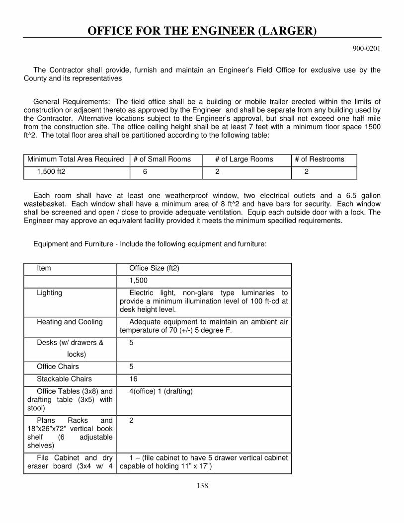
138
OFFICE FOR THE ENGINEER (LARGER)
900-0201
The Contractor shall provide, furnish and maintain an Engineer’s Field Office for exclusive use by the
County and its representatives
General Requirements: The field office shall be a building or mobile trailer erected within the limits of construction or adjacent thereto as approved by the Engineer and shall be separate from any building used by the Contractor. Alternative locations subject to the Engineer’s approval, but shall not exceed one half mile from the construction site. The office ceiling height shall be at least 7 feet with a minimum floor space 1500 ft^2. The total floor area shall be partitioned according to the following table:
Minimum Total Area Required # of Small Rooms # of Large Rooms # of Restrooms
1,500 ft2 6 2 2
Each room shall have at least one weatherproof window, two electrical outlets and a 6.5 gallon wastebasket. Each window shall have a minimum area of 8 ft^2 and have bars for security. Each window shall be screened and open / close to provide adequate ventilation. Equip each outside door with a lock. The Engineer may approve an equivalent facility provided it meets the minimum specified requirements.
Equipment and Furniture - Include the following equipment and furniture:
Item Office Size (ft2)
1,500
Lighting Electric light, non-glare type luminaries to provide a minimum illumination level of 100 ft-cd at desk height level.
Heating and Cooling Adequate equipment to maintain an ambient air temperature of 70 (+/-) 5 degree F.
Desks (w/ drawers &
locks)
5
Office Chairs 5
Stackable Chairs 16
Office Tables (3x8) and drafting table (3x5) with stool)
4(office) 1 (drafting)
Plans Racks and 18”x26”x72” vertical book shelf (6 adjustable shelves)
2
File Cabinet and dry eraser board (3x4 w/ 4
1 – (file cabinet to have 5 drawer vertical cabinet capable of holding 11” x 17”)

139
colored dry markers)
Fire Proof File Cabinet 2 – 4 (minimum) drawer vertical cabinet capable of holding 11” x 17” each equipped w/ hanging folder systems and 100 hanging folders
Portable Water Cooler If cooler is used, maintain adequate water supply.
Telephone Service w/ telephone in each room
Local Service Only
Answering Machine 1
High Speed Internet
Service
DSL or Cable Modem with one (1) wireless router and a hardwired network with min one (1) connection port in each room. Includes all computer drivers, software, wiring, etc. and technical support provided by the Contractor to connect to Engineer’s computer(s) and validate remains operational during the contract period.
Facsimile Machine 1- including all supplies, expendables, and maintenance
Printer/Copier/Scanner 1-capable of making 11" x 17" copies/scans without reductions, all supplies, expendables, and maintenance
Restrooms An enclosed room with toilet and sink with running water, and with proper sewer connection or septic tank. Number of restrooms as specified.
Storage Room A room large enough to store surveying instruments and testing equipment. Provide the room with lock and electrical outlets.
Maintenance Maintain all facilities and furnished equipment in good working condition.
Fire Extinguisher Two, 5 pound, non-toxic, dry chemical, fire extinguishers meeting Underwriters’ Laboratories, Inc.
Security Provide adequate security of all facilities and furnished equipment.
Occupancy and Maintenance: Provide a field office for the County and its representative’s use, no later than the date of Notice-to-Proceed and remaining for 10 days after final acceptance, unless the County requests removal earlier. Do not begin work before the field office is available for the County’s use. Office shall be identified with a suitable sign, approved by the Engineer.
Maintain the field office in good condition and appearance, inside and out. The Contractor will provide daily janitorial services and supplies, including paper supplies for the restrooms. After the designated period, remove all portable building or trailers, fencing, surfacing and utilities and leave the areas with a finish soil layer cleaned, and seeded, if required; and in an acceptable condition.
The Contractor shall pay for all utilities except long distance telephone calls made by the Engineer or his representatives, for which the Contractor shall be reimbursed by the County. The Contractor, at his expense, shall obtain all required permits for electrical, water and sewer work and installations, shall have all required electrical, water and sewer inspections made, and shall be responsible for all repairs and maintenance

140
required in connection with permits and inspections. Permit fees under the County of the Board of County Commissioners are waived. All other permit fees shall be paid by the Contractor and shall be included in this pay item Office for the Engineer.
The Contractor shall also provide, at a minimum, a 20 ft. x 20 ft. fenced area exclusively for the County’s use to secure the County vehicles, during the length of the project.
Basis of Payment:
Payment for the furnishing of the facility and secured area specified under this Section, and all labor, materials, equipment and services incidental thereto, shall be made for under the pay item for Office For The Engineer (Larger) and shall be made at the contract price per day, except for long distance telephone calls made by the Engineer or his representatives, for which the Contractor shall be reimbursed by the County.
The County reserves the right to assess liquidated damages against the Contractor for non-compliance with this section. Liquidated damages shall not exceed $500.00 per day for each day of non-compliance.
Payment per day by the County to the contractor shall commence on the day that the contractor provides a facility that satisfies the requirements of this specification.

141
POND CLAY LINER
900-0300
The work specified under this Section consists of the furnishing and installation of a pond clay liner, in accordance with the details and notes shown in the Plans. The material of the clay liner shall exhibit a hydraulic conductivity of no greater than 1 x 10⁻⁵ cm/sec.
Except for that work excluded under other provisions of this Section, and except as provided for under other Sections of these specifications, the work to be performed under this Section shall consist of all excavation, the furnishing, placement and compaction of all fill material, all grading, the shaping or reshaping of the clay liner and all other earthwork operations and construction activities required to complete the Clay Liner installation. The work also includes the backfill over the clay liner up to the lines, grades and locations of the pond bottom with the material specified on the Plans.
The Clay Liner shall be constructed in conformity with the lines, grades, details and specification notes shown in the Plans, and as directed by the Engineer.
Basis of Payment
The pay quantities for the work specified under this Section shall be one lump sum quantity for Pond Clay Liner and shall include all work and materials described and specified herein.
The work specified under this Section shall be paid for at the contract lump sum price.

142
COFFERDAMS
900-1060
The work specified in this Section consists of the construction of cofferdams to facilitate excavation of bridge foundations, box culverts, storm sewers and all other pipe lines, retaining walls, headwalls for pipe culverts and drains, drop inlets, manholes and similar structures. It shall also include:
1) the construction & removal of cofferdams, excavation, sheeting, bracing, etc.
2) pumping or otherwise dewatering foundations.
3) the removal & disposal of any existing structures or portions of structures not covered by other items in the contract, including foundations, abutments, piers, wings, & all other materials, obstructions, etc., found necessary to clear the site for the proposed work.
4) backfilling, disposing of surplus material & final cleaning, as may be necessary for the proper execution of the work. This Section shall not include the work of excavating for bases or pavements, curbs & gutter, valley gutter, ditch pavement or rubble gutter. All work shall conform to the requirements of Section 125-3 of the FDOT Specifications, as amended herein, and where specified herein or on the Plans.
5) Additional requirements stipulated in environmental permits.
Basis of Payment
The quantity for Cofferdam shall be the number each or lump sum and shall include all work and materials described and specified herein.
The work specified under this Section shall be paid for at the contract per each price or lump sum price for Cofferdam.

143
UNSPECIFIED WORK (ALLOWANCE)
999-0000
The work under this Section includes an allowance for any unspecified work that may be associated with the work in this contract or as otherwise identified by the Engineer. Any amount of extra work and/or alterations to this contract charged to the allowance “Unspecified Work” shall be fully documented and approved in writing, in advance, by the Engineer. All work performed under the allowance of “Unspecified Work” shall be completed in accordance with all conditions and requirements of this contract and shall include the work to be done by all necessary subcontractors and/or suppliers.
“Unspecified Work” shall mean the stated fixed sum of money to be used only at the Engineer’s specified direction. The particular requirements and items for the allowances will be provided to the Contractor at the appropriate time and shall apply only to additional items over and above those specified/indicated in the plans for this contract.
For equipment under the control of the Contractor through direct ownership, leasing, renting or other method of acquisition not included in the bid, the Contractor shall furnish cost data, which may assist the Engineer in the establishment of an equitable rate.
Time Frame
When Contractor is requested, in writing by the County, to provide a cost for unspecified work, the Contractor will provide a submittal of the cost to the County within 21 calendar days of receiving written request. After receipt of the Contractor’s cost submittal, the County will have 21 calendar days to negotiate, approve or reject the Contractor’s cost for proposed work in accordance with the contract specifications. If the County provides to the Contractor written approval of Contractor’s cost submittal for proposed unspecified work, then the Contractor may proceed with commencing the unspecified work.
Basis of Payment
The work in this Section shall be paid for by a portion of the allowance under “Unspecified Work” in the Schedule of Values of this contract. Use of any portion of this pay item shall require written pre-approval by the Engineer. This work, materials, and equipment, when required, will be ordered in writing by the Engineer, at a lump sum price or at a non lump sum price. Price negotiations will consider reasonable market values (at the time of construction) for proposed items.
Lump Sum
When a lump sum price is used, the lump sum price will be determined by negotiation, and only require written pre-approval by the Engineer as backup documentation for payment purposes.
Non Lump Sum
When a non lump sum price is used, compensation shall be limited to the Contractor’s reasonable costs plus markup percentages stipulated in this contract. The basis of the non lump sum negotiated prices and subcontractor invoices will be included in pay application; Copies of invoices, equipment cost estimations and other supporting documentation will be included.
Payment Item
Item No. 999-0000 Unspecified Work – per each

144
SURVEY WORK (ALLOWANCE)
999-0003
This specification shall only be applicable when pay item 999-0003 is used for Survey Work
(Allowance) in a specific contract.
The work under this Section includes an allowance for survey work that may be associated with the work in this contract identified by the Engineer. Any amount of survey related work in this contract charged to the allowance “Survey Work” shall be fully documented and approved in writing, in advance, by the Engineer. All work performed under the allowance of “Survey Work” shall be completed in accordance with all conditions and requirements of this contract and shall include the work to be done by all necessary subcontractors and/or suppliers.
“Survey Work” shall mean the stated fixed sum of money to be used only at the Engineer’s specified direction for survey requirements. The particular survey requirements and items for the allowances will be provided to the Contractor at the appropriate time that survey scope is determined.
For equipment under the control of the Contractor through direct ownership, leasing, renting or other method of acquisition not included in the bid, the Contractor shall furnish cost data, which may assist the Engineer in the establishment of an equitable rate.
The Contractor shall employ or retain the services of a Florida registered Professional Land Surveyor to satisfy all the requirements specified in this specification and in section “SURVEY AND LAYOUT” of the contract specifications. The Contractor shall be responsible to perform all survey related work in acceptable standard methods. All field books and calculations, related to layout, shall be available to the engineer upon request, for a period of one year after construction completion.
SURVEY AND LAYOUT BY CONTRACTOR
The work specified under this Section consists of all materials and labor necessary to complete the survey and layout by the Contractor, in accordance with the section “SURVEY AND LAYOUT” in the contract specifications, to completely construct the project, to the satisfaction of the Engineer. This work shall include providing all lines, grades, boundaries and required survey and/or layout necessary to construct and inspect the project. All right-of-way and easement boundaries and centerline control points shall be established and maintained through the contract period by the Contractor.
QUANTITY MEASUREMENTS SURVEY BY CONTRACTOR
The work specified under this Section consists of all materials and labor necessary to complete all quantity measurements by the Contractor, to the satisfaction of the Engineer. The Contractor shall provide summaries to the County, signed and sealed by a Florida registered Professional Land Surveyor, listing all items measured, measurement quantities and dates of measurements, within 5 days after receiving written request from the County. The items that require measurements include, but are not limited to:
Roadway items (surface course, base, stabilization, curb, sidewalks, etc.)
Drainage items (inlets, pipes, box culverts, underdrains, etc.)
Other items (Handrails, ditch pavement, gabions, guardrail, fencing, gates, landscaping, sod, fill,
excavation, etc.)
In the case of dispute in quantity measurements, the County reserves the right to have Pinellas County Survey Department verify all measurements and calculations. Contractor’s Surveyor shall make all field books and calculations available for review by the engineer or his designee.

145
PERMITTING AS-BUILT SURVEY REQUIREMENTS BY CONTRACTOR
The work specified under this Section consists of all materials and labor necessary to complete all required permitting as-built requirements, to the satisfaction of the Engineer. The Contractor shall provide the as-built survey to the County, signed and sealed by a Florida registered Professional Land Surveyor, within 25 days after receiving written request from the County. Contractor’s Surveyor shall make all field books and calculations available for review by the engineer or his designee.
The items that require as-built surveying shall include:
Control structures - weir and grate elevations
Control structures - weir and grate dimensions
Ponds - top of bank, toe of slope, etc.
Other items (to be provided by Engineer of Record)
UTILITY AS-BUILT SURVEY REQUIREMENTS
The work specified under this Section consists of all materials and labor necessary to complete all required as-built survey requirements for Pinellas County Utility Lines or other Utility Lines specifically listed in these specifications, to the satisfaction of the Engineer. The Contractor shall provide the utility as-built survey to the County, signed and sealed by a Florida registered Professional Land Surveyor, within 25 days after receiving written request from the County. Contractor’s Surveyor shall make all field books and calculations available for review by the engineer or his designee.
The items that require utility as-built surveying shall include:
Pinellas County Sewer Line
Pinellas County Water Line
Other project specific Utility Lines
Basis of Payment
The work in this Section shall be paid for by a portion of the allowance under “Survey Work” in the Schedule of Values of this contract. Use of any portion of this pay item shall require written pre-approval by the Engineer. This work, materials, and equipment, when required, will be ordered in writing by the Engineer, at a lump sum price or at a non lump sum price.
LUMP SUM
When a lump sum price is used, the lump sum price will be determined by negotiation, and only require written pre-approval by the Engineer as backup documentation for payment purposes.
NON LUMP SUM
When a non lump sum price is used, compensation shall be limited to the Contractor’s reasonable costs plus markup percentages stipulated in this contract. The basis of the non lump sum negotiated prices and subcontractor/surveyor invoices will be included in pay application; Copies of invoices, equipment cost estimations and other supporting documentation will be included.
Payment Item
Item No. 999-0003 Survey Work (allowance) – per each