standard residential deck details · standard residential deck details ... building structural. all...
TRANSCRIPT
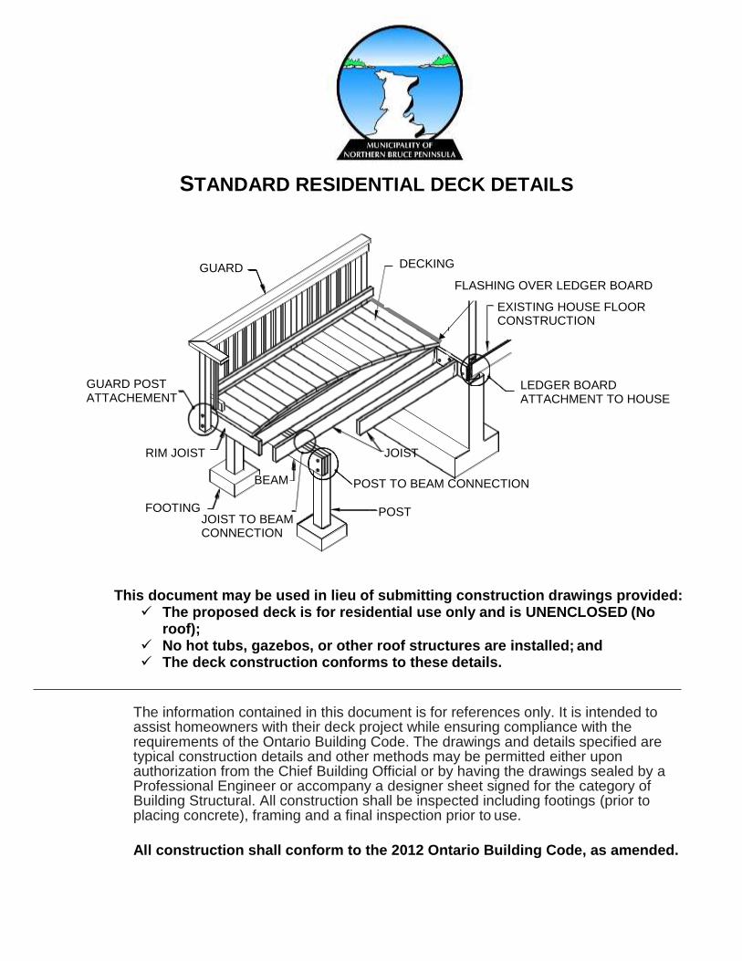
GUARD
EXISTING HOUSE FLOOR CONSTRUCTION
DECKING
GUARD POST ATTACHEMENT
RIM JOIST
FOOTING
LEDGER BOARD ATTACHMENT TO HOUSE
POST
JOIST
POST TO BEAM CONNECTION
FLASHING OVER LEDGER BOARD
BEAM
JOIST TO BEAM CONNECTION
STANDARD RESIDENTIAL DECK DETAILS
This document may be used in lieu of submitting construction drawings provided: The proposed deck is for residential use only and is UNENCLOSED (No
roof); No hot tubs, gazebos, or other roof structures are installed; and The deck construction conforms to these details.
The information contained in this document is for references only. It is intended to assist homeowners with their deck project while ensuring compliance with the requirements of the Ontario Building Code. The drawings and details specified are typical construction details and other methods may be permitted either upon authorization from the Chief Building Official or by having the drawings sealed by a Professional Engineer or accompany a designer sheet signed for the category of Building Structural. All construction shall be inspected including footings (prior to placing concrete), framing and a final inspection prior to use.
All construction shall conform to the 2012 Ontario Building Code, as amended.

BUILDING PERMIT APPLICATION REQUIREMENTS (To be completed by the Building Department)
Complete applications may be accepted by mail, e-mail, facsimile, or at the office.
DECKS AND SEPTIC SYSTEMS
Decks may not be constructed on septic systems
A clearance distance of 5’ (1.5m) is required from the deck pier to the septic tank in accordance with 8.2.1.6.A, Div. B, OBC
A clearance distance of 16’ (5m) is required from the deck pier to the closest distribution line in accordance with 8.2.1.6.B, Div. B, OBC.
Description
Required
Received
Comments
Ap
pli
ca
ble
Law
Zoning By-Law Compliance Comprehensive Zoning By- Law 2002-54
Ministry of Transportation (MTO)
Contact MTO: 519-372-4045
Owners Authorization letter If the Owner is not the Applicant
Permit Fee $100.00
Fo
rms
Building Permit Application
Schedule 1: Designer Information
House
Note: House category required for qualified designer
Pla
ns
Site Plan Include septic bed and tank location
Deck Framing Plan
***If not using NBP Deck Details***
Exterior Elevations
Cross Section – including guards and connection to structures

JOISTS, BEAMS AND PIER SIZING
The Part 9 snow load for all decks within the Municipality of Northern Bruce Peninsula shall have a Specified Snow Load of 1.9kPa. If the live load will exceed 1.9kPa including hot tubs or drift loading it must be designed by a competent person (Professional Engineer).
JOIST SPAN
Size Spacing Span
2 x 8
12” o/c 12’-0”
16” o/c 11’-0” 24” o/c 10’-0”
2 x 10
12” o/c 14’-0” 16” o/c 13’-0” 24” o/c 12’-0”
2 x 12 12” o/c 16’-0” 16” o/c 14’-0”
Note: All lumber SPF or better - Solid blocking required if span exceeds 6’-11”
BEAM SPANS
Joist span Post Spacing
6’-0” 8’-0” 10’-0” 12’-0” 14’-0”
6’-0” 2 ply 2x8 2 ply 2x8 3 ply 2x8 3 ply 2x10 3 ply 2x12 4 ply 2x10
8’-0” 2 ply 2x8 2 ply 2x8 3 ply 2x8 3 ply 2x10 3 ply 2x12 4 ply 2x10
10’-0” 2 ply 2x8 3 ply 2x8 3 ply 2x8 3 ply 2x10 3 ply 2x12 4ply 2x10
12’-0” 3 ply 2x8 3 ply 2x8 3 ply 2x10 4 ply 2x8
3 ply 2x10 3 ply 2x12 4ply 2x10
14’-0” 3 ply 2x8 3 ply 2x10 3 ply 2x10 4 ply 2x8
3 ply 2x12 4ply 2x10
3 ply 2x12 4ply 2x10
FOOTING SIZES (Diameter in inches)
Joist Span Pier Spacing
6’-0” 8’-0” 10’-0” 12’-0”
6’-0” 10” 10” 14” 14”
8’-0” 10” 14" 17" 17”
10’-0” 14” 14” 17” 17”
12’-0” 14” 17” 17” 21”

JOIST SPAN MAX. 2'•0"
CANTILEVER
6" x 6 " MIN. WOOD POST ANCHORED TO CONC. PIER WITH METAL SHOE & 1/2" DIA. BOLT
GRADE
8" MIN.
DECK JOISTS TO BE ATTACHED TO WOOD BEAM WITH A MIN. TWO 3•1/4" NAILS
EXISTING FLOOR STRUCTURE TO REMAIN
WOOD BEAM WITH 2"x4" GUSSETS ON BOTH SIDES OF POST WITH THREE 3" SCREWS OR 3"x6•1/2" METAL CONNECTOR
POURED CONCRETE PIER MIN. 4'•0" BELOW GRADE ON UNDISTURBED SOIL
HEADER LAG•BOLTED TO FOUNDATION OR STRUCTURAL FRAMING WITH 1/2" DIA. BOLTS @ 24" O.C. ON CENTRE. DECK JOISTS ATTACHED WITH JOIST HANGERS.
CONSTRUCTION DETAILS
BUILDING SECTION OF DECK CONSTRUCTION
CONSTRUCTION NOTES:
Maximum cantilever for joists and beams beyond supports is 24” (600mm).
Typically, column pad footings or the use of pre-engineered concrete footing forms are required beneath the concrete pier unless an acceptable alternative is proposed.
Footings/piers shall bear on undisturbed soil down a min. 48” (1.2m) below grade or directly on bedrock.
6"
2"
MIN
.
4'•0"
MIN
.

2 PLY beam option only;
3 PLY beam is
not permitted
POST CAP; ATTACHEMENT, FASTENERS PER MANUFACTURERS INSTRUCTIONS
(2) 1/2" DIA. THROUGH•BOLTS WITH WASHERS
3•MEMBER BEAMS MUST USE POST CAP OPTION
BEAM MUST BEAR ON 6x6 NOTCH
MAXIMUM UNSUPPORTED HEIGHT OF 6”X6” POST = 12’-0”
NOTCH POST TO PROVIDE BEAM WITH FLUSH AND TIGHT BEARING
6x6 POST
OPTION 1 OPTION 2
CONNECTIONS
CONNECTION OF FLOOR JOISTS TO BEAM SUPPORT
POST TO BEAM OPTIONS DETAIL FOR FRAMING AROUND A CHIMNEY OR BAY WINDOW
CHIMNEY OR BAY WINDOW
6'•0" MAXIMUM DECKING MAY EXTEND 6" MAXIMUM
DOUBLE JOIST
LEDGER BOARD
CHIMNEY OR BAY WINDOW
LEDGER BOARD
DOUBLE JOIST, EACH SIDE
DOUBLE JOIST HANGER, TYPICAL
DOUBLE HEADER (2) LEDGER BOARD FASTENERS
PLAN VIEW SECTION
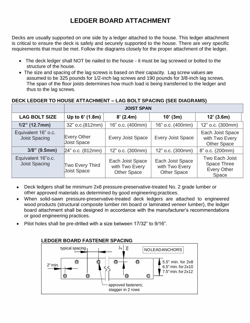
NO LEAD ANCHORS typical spacing
2" min. 5.5" min. for 2x8
6.5" min. for 2x10
7.5" min. for 2x12
approved fasteners; stagger in 2 rows
LEDGER BOARD ATTACHMENT
Decks are usually supported on one side by a ledger attached to the house. This ledger attachment is critical to ensure the deck is safely and securely supported to the house. There are very specific requirements that must be met. Follow the diagrams closely for the proper attachment of the ledger.
The deck ledger shall NOT be nailed to the house - it must be lag screwed or bolted to the
structure of the house.
The size and spacing of the lag screws is based on their capacity. Lag screw values are assumed to be 325 pounds for 1/2-inch lag screws and 190 pounds for 3/8-inch lag screws. The span of the floor joists determines how much load is being transferred to the ledger and thus to the lag screws.
DECK LEDGER TO HOUSE ATTACHMENT – LAG BOLT SPACING (SEE DIAGRAMS) JOIST SPAN
LAG BOLT SIZE Up to 6’ (1.8m) 8’ (2.4m) 10’ (3m) 12’ (3.6m)
1/2” (12.7mm) 32” o.c.(812mm) 16” o.c. (400mm) 16” o.c. (400mm) 12” o.c. (300mm)
Equivalent 16” o.c. Joist Spacing Every Other
Joist Space Every Joist Space Every Joist Space
Each Joist Space with Two Every
Other Space
3/8” (9.5mm) 24” o.c. (812mm) 12” o.c. (300mm) 12” o.c. (300mm) 8” o.c. (200mm)
Equivalent 16”o.c. Joist Spacing Two Every Third
Joist Space
Each Joist Space with Two Every
Other Space
Each Joist Space with Two Every
Other Space
Two Each Joist Space Three Every Other
Space
Deck ledgers shall be minimum 2x8 pressure-preservative-treated No. 2 grade lumber or other approved materials as determined by good engineering practices.
When solid-sawn pressure-preservative-treated deck ledgers are attached to engineered wood products (structural composite lumber rim board or laminated veneer lumber), the ledger board attachment shall be designed in accordance with the manufacturer’s recommendations or good engineering practices.
Pilot holes shall be pre-drilled with a size between 17/32” to 9/16”.
LEDGER BOARD FASTENER SPACING
2"
mi

LEDGER BOARD CONNECTIONS
LEDGER BOARD CONNECTION TO RIM BOARD
LEDGER BOARD CONNECTION TO POURED FOUNDATION WALL
LEDGER BOARD CONNECTION TO BLOCK WALL
embed anchors
2½
minimum
2
existing concrete
or solid masonry wall
to resist corrosion and
decay, this area should be caulked
deck joist
2 1" diameter expansion
anchors with washers
joist hanger
ledger board must be greater than
or equal to the size of the joist
embed anchors
31" minimum 2
to resist corrosion and
decay, this area should
be caulked
deck joist
existing hollow
masonry wall 2 1" diameter
approved
epoxy anchors
with washers
8" block wall
minimum
joist hanger
ledger board must be greater than
or equal to the size of the joist
exterior sheathing
existing house stud wall
remove siding at ledger
prior to installation
continuous flashing with drip edge
Rim joist and
sill plate
deck joist
2
1" diameter lag
floor joist or wood I-joist
existing
foundation wall
joist hanger
screws or through-bolts
with washers
ledger board must be greater than
or equal to the size of the joist
3 ½ minimum
2 ½ minimum

STRUCTURAL REQUIREMENTS POST SIZING
DECK SUPPORT AND POST SIZING:
Minimum post size is 140mm X140mm (6”X6”). PROHIBITED CONNECTION
DECK ELEVATION PLAN AND DECK LATERAL SUPPORT
MINIMUM SIZE OF LOAD BEARING ELEMENTS (OBC SB-7 2.1.1):
GUARD Element Post Top Rail Bottom Rail Picket / Baluster
Minimum size inches (mm)
4” x 4” nominal (89mm x 89mm)
2” x 4” nominal (38mm x 89mm)
2” x 4” nominal (38mm x 89mm)
1 9/32” x 1 9/32” (32mm x 32mm)
MINIMUM SIZE OF FLOOR ELEMENTS (OBC SB-7 2.1.3):
FLOOR Element Minimum Size, in. (mm)
Dimensional lumber
Decking
5/4” x 6” nominal (25mm x 140mm) when each plank is fastened with 2 - 2 1/2” (63mm) nails
2” x 4” nominal (38mm x 89mm) when each plank is fastened with 2 – 3” (76mm) nails
Joists 2” x 8” nominal (38mm x 184mm)
(1) 3/8" DIA. THRU•BOLT WITH WASHERS, TYP.
PROVIDE BLOCKING WHEN JOISTS DO NOT ALIGN WITH POSTS
BEAM BEAM 2’
2’
2x4, TYPICAL
JOIST AT POST LOCATIONS
BRACING PARALLEL TO BEAM BRACING PERPENDICULAR TO BEAM
2' 2
’’
12
'•0
" M
AX
IMU
M

GUARDS REQUIRED GUARDS
OPTION “A”: POST AND RAIL SYSTEM CONSTRUCTION NOTES
Decking is omitted from the Post Detail plan view & axonometric view for clarity.
Joists spaced max. 16” (400mm) O.C. Max. post spacing 3’-11” (1.2m)
All fasteners shall be corrosion resistant
All lumber shall be decay resistant and all cut ends of preservative treated lumber shall be treated to prevent decay.
Min. height of guard where deck height is between 24” (600mm) & 5’-11” above grade: 35” (890mm).
Min. height of guard where deck height exceeds 5’-11” (1.8m) above grade: 42” (1070mm).
Maximum 4” opening between pickets and no member or attachment between 5-1/2” and 35” shall facilitate climbing.
POST AND RAIL CONNECTION / PICKET DETAILS
PICKET 2"x2" MAX. 4" BETWEEN
PLAN BOTTOM RAIL
BOTTOM RAIL 2"x4"
#7x2" SCREWS @ 12" O.C.
2•2" NAILS
FRONT ELEVATION SIDE ELEVATION
MIN. 20 GAUGE FRAMING ANCHOR NAILS AS RECOMMENDED BY MANUFACTURER
POST
FRAMING ANCHOR
RAILING 2"x4"
PLAN AXONOMETRIC
FRONT ELEVATION SIDE ELEVATION
TWO 5/16" MACHINE BOLTS WITH 1•1/4" FENDER WASHERS EACH
SIDE
FLOOR JOIST
4"x4" POST RIM JOIST
THREE 3•1/4" NAILS
PLAN AXONOMETRIC
DECKING
1"
1"
1"
CENTRE OF POST
FRONT ELEVATION SIDE ELEVATION

GUARDS
OPTION “B”: CANTILEVERED PICKET SYSTEM

GUARDS
(Cantilevered Picket Continued)
CONSTRUCTION NOTES:
All fasteners shall be resistant to corrosion.
All lumber shall be decay resistant. All cut ends of preservative treated lumber shall be treated to prevent decay.
Composite decking is required to have BMEC or CCMC approvals
Pre-engineered guard systems are required to have Ontario Engineering
Any guard assembly that is site manufactured, such as wood/glass guards is required to be engineered
A privacy wall/ fence boards is permitted if constructed as a guard and should be discussed with Building Inspector prior to constructing
NOTE: 1. TWO #8x3" SCREWS INTO 2"x4" RAIL AND ONE #8x3" SCREW INTO TOP RAIL 2. PROVIDED A MINIMUM OF 10 PICKETS BEYOND THE RETURN IF END RESTRAINT OF THE GUARD IS PROVIDED BY THIS RETURN DETAIL ONLY
THREE #8x3" SCREWS
PLAN TOP RAIL
AXONOMETRIC
TOP RAIL
2"x4" RAIL

STAIR DETAILS HANDRAIL and STAIR CONNECTIONS
CONSTRUCTION NOTES:
Handrails are required to be installed on every stair with more than 3 risers. Provide a guard
on both sides of stair where the stair exceeds 6 risers.
Height of handrails (where guards not required) on stairs shall be between 34” (865mm), and
38” (965mm).
Height of guard for a deck between 24” (600mm) and 5’-11” (1.8m) above grade is 35” Height
of guard for a deck more than 5’-11” (1.8m) above grade is 42” (1070mm)
Maximum 4” openings between pickets and no member or attachment shall facilitate climbing
All steps to be equal rise and run between landings.