standard operating procedure for stoe stadi p (imserc)
TRANSCRIPT

Standard Operating Procedure for STOE STADI P (IMSERC)
1/15 Integrated Molecular Structure Education and Research Center Northwestern University
Follow the general steps when computer has been restarted or last user has accidentally logged off. Please
remember to:
1. Leave lab tables clean and tools/accessories organized
2. Return any unused masks
3. Do not unscrew all the way the mask mounting screws of the holders, one turn clockwise is sufficient
4. Log off from NUCore when you’re done with the experiment
5. Leave the acquisition software open when you’re done with the measurement
6. Report problems with the instrument at http://imserc.northwestern.edu/contact-issue.html
GENERAL STEPS
1. Pack your powdered sample into the appropriate holder
a. Use the flat plate disc holder in transmission mode for qualitative analyses on powder sandwiched
between acetate, polyimide, or mylar foils (high throughput option up to 30 flat plates)
b. Use glass capillaries in Debye-Scherrer
(transmission) mode for samples in liquid or
air sensitive samples (high throughput
option up to 10 capillaries)
c. Use polyimide (or glass) capillaries in Debye-
Scherrer (transmission) mode for
quantitative analyses (e.g., Rietveld)
d. Use glass capillaries (pyrex, borosilicate,
quartz) for high temperature experiments with the in-situ furnace
2. Make sure instrument is idle by checking that the X-ray safety red light is turned off. Login in NUCore to have
the screen of the computer turned on
3. Start the ‘WinXPOW’ software (icon on the desktop) and
a. (Optional) Press on ‘Change Directory’ button to select your personal working directory under your
group’s folder. Create a folder for the new files
b. Under the ‘Diffract.1’ menu select ‘Diffractometer Control’. It will take a few seconds to initialize hardware
before the control window is accessible

Standard Operating Procedure for STOE STADI P (IMSERC)
2/15 Integrated Molecular Structure Education and Research Center Northwestern University
i. ‘Diffractometer Control’ (PowDat) shown the acquisition parameters of the loaded or newly created
file. You can load a previous measurement (*.dat) from the menu ‘File’ and option ‘Open’, in case you
want to reuse the same acquisition parameters
every time
ii. At the bottom of the ‘Diffractometer Control’
window, information about the wavelength,
geometry, detector, position of omega and 2theta,
and energy threshold of the detector are shown
4. Define the ‘Scan Mode’ of your measurement by selecting
the option under the ‘Ranges’ menu or you can click on the
‘M’ button. Specific configuration settings for each
geometry (e.g., transmission plate, capillary, etc.) are
described in the next pages. Generally, ‘Scan Mode’ relates
to the type of sample holder in use:
a. ‘Transmission’ scan mode for flat plate discs usually
keeps a constant 2:1 between 2θ- and ω-position.
However, the exact relation is defined with the ‘Scan Type’ option
b. ‘Reflection’ scan mode adds a constant offset of 90º to the ω-position to account for the different
orientation of the sample surface relative to the primary beam
3
4 5
6 7

Standard Operating Procedure for STOE STADI P (IMSERC)
3/15 Integrated Molecular Structure Education and Research Center Northwestern University
c. ‘Debye-Scherrer’ scan mode keeps the ω-position constant at 0º for every 2θ –position
5. ‘Scan Type’ option is activated only if the ‘Scan Mode’ parameter is not set to Debye-Scherrer. Its setting over-
rides the default scan modes for ‘Transmission’ and ‘Reflection’. Options are:
a. ‘2Theta’ defines a scan with moving detector, but the ω-position kept constant at a user-defined value
b. ‘Omega’ is a scan with fixed detector position and moving ω-position (rocking curve)
c. ‘2Theta/Omega’ invokes the normal 2:1 coupling between 2θ-and ω-position during the scan
d. ‘Independent’ let you define 2θ and ω movements independently from each other, e.g., a certain ω-offset
and/or a 1:1 ratio between 2θ- and ω-step width may be entered in the ‘Edit Ranges’ dialog box
6. Set the ‘PSD Mode’ which controls the movement of the detector during measurement. You can select
between:
a. ‘Moving’ (most common mode) where the detector will be moved during a measurement, allowing a scan
range as wide as the diffractometer allows
b. ‘Stationary’ where the detector will stay at one defined position. The total scan range could not be wider
than the detector itself (~ 19º)
c. ‘Cont. Scan’ where the detector will move continuously during the scan. Use this mode for long collections
(>1 h) for better signal-to-noise ratio
7. Set the ‘Omega Mode’ for the position of the ω-angle. Options are:
a. ‘Fixed means that for every PSD 2θ-position the ω-position will be set to 2θ/2 and will remain at this
position for all the measuring time of this PSD step
b. ‘Moving’ means that the ω-circle is continuously moved during data collection which usually requires
longer step times and thus should only be used if additional particle randomization is required

Standard Operating Procedure for STOE STADI P (IMSERC)
4/15 Integrated Molecular Structure Education and Research Center Northwestern University
RUN SAMPLES MANUALLY WITH THE TRANSMISSION HOLDER WITHOUT THE AUTOSAMPLER
1. Make sure the transmission stage is mounted onto the
diffractometer, otherwise see a Staff
2. If stage is spinning and/or occupied with a sample holder, you
need to
a. Stop any rotation by turning the ‘Sample spinner’ dial
counter-clockwise until it clicks. Dials are located on the
left side of the goniometer base behind the arm of the
detector
b. Remove the sample holder and leave it on the sample table outside the enclosure of
the diffractometer
c. Mount your sample holder onto the stage. Refer to the attached picture for the right
orientation of the sample holder on the stage. The mask should face the X-ray source
and the side of the holder facing the detector should have only one hole visible in the
middle of the holder/mask.
d. Turn on spinning by rotating the ‘Sample spinner’ clockwise
e. Close windows of the enclosure and make sure the green light next to the top
emergency button is on
3. Under ‘Ranges’ menu, select the ‘Scan Mode’ option
(or press the ‘M’ icon) and set
o ‘Scan mode’ to ‘Transmission’
o ‘PSD mode’ to ‘Moving’
o ‘Scan Type’ to ‘2Theta/Omega’
o ‘Omega mode’ to ‘Fixed’
o ‘Points to be added’ to ‘1’
4. Under ‘Ranges’ menu, select the ‘Scan Range’ option.
On the ‘Edit Range’ window
o Click on the ‘+’ button to add a scan range
o Double click on the new scan range you just added and
a. Edit the ‘2theta range’ accordingly
Transmission attachment
1
2a
Side facing detector Side facing X-rays
2c
Door safety light
2e

Standard Operating Procedure for STOE STADI P (IMSERC)
5/15 Integrated Molecular Structure Education and Research Center Northwestern University
b. Define the ‘Step’ of the detector, typically 2-6º. This step is different than the step of the intensity
points in your powder pattern that is fixed to 0.015º. Our
detector can cover a solid angle of ~19º with a single step,
therefore with a step of 1º, the same 2theta region will be
measured 19 times
c. Set the integration ‘Time/PSD Step’ in seconds, typically 10-
20 s. Signal-to-noise ratio improves if you measure the same
2theta range multiple times instead of measuring once with
a longer exposure (see ‘Scan usage’ below)
o Keep adding more ranges according to your needs, e.g., add a
range with longer exposure for the high angle reflections, etc.
5. Under ‘Ranges’ menu, select the ‘Scan Usage’ option
o Select ‘Single Sample’ if you want to measure
your sample/scan range only once
o Select ‘Repetition’ if you want to measure
your sample/scan range multiple time for
improving the signal-to-noise ratio. You have
the option to add a ‘Waiting time’ in case you
are interested in a time dependent
measurement, e.g., transformation,
decomposition, etc.
6. Start the measurement by clicking on
‘Measurement’ under the ‘Measurement’ menu or clicking on the ‘C’ icon. Give a file title for the file header
4b
5

Standard Operating Procedure for STOE STADI P (IMSERC)
6/15 Integrated Molecular Structure Education and Research Center Northwestern University
RUN SAMPLES WITH THE TRANSMISSION HOLDER USING THE AUTOSAMPLER (HIGH THROUGHPUT)
1. Make sure the transmission stage and autosampler are mounted onto the diffractometer, otherwise see a
Staff to set up the attachments for you
2. If stage is spinning and/or occupied with a sample
holder, you need to
a. Stop any rotation by turning the ‘Sample spinner’
dial counter-clockwise
b. Remove the sample holder and leave it on the
sample table outside the enclosure of the
diffractometer
c. Install your sample holder(s) into the ‘Stack’ tube
and make sure the ‘Deposit’ tube is empty. Refer
to the attached picture for the right orientation of the sample holder in the tube. The
side of the holder facing the detector should have only one hole visible in the middle
of the holder/mask. There is an extra empty tube at the back corner of the
diffractometer that you can use as a new ‘Deposit’ or ‘Stack’ tube
d. Turn on spinning by rotating the ‘Sample spinner’ fully clockwise
e. Close windows of the enclosure and make sure the green light next to the top
emergency button is on
3. Under ‘Ranges’ menu, select the ‘Scan Mode’ option and set
a. ‘Scan mode’ to ‘Transmission’
b. ‘PSD mode’ to ‘Moving’
c. ‘Scan Type’ to ‘2Theta/Omega’
d. ‘Omega mode’ to ‘Fixed’
e. ‘Points to be added’ to ‘1’
4. Under ‘Ranges’ menu, select the ‘Scan Range’ option.
On the ‘Edit Range’ window
a. Click on the ‘+’ button to add a scan range
b. Double click on the new scan range you just added and
i. Edit the ‘2theta range’ accordingly
Autosampler attachment
2a
Side facing detector Side facing X-rays
2c
Door safety light
2e

Standard Operating Procedure for STOE STADI P (IMSERC)
7/15 Integrated Molecular Structure Education and Research Center Northwestern University
ii. Define the ‘Step’ of the detector, typically 2-6º. This step is different than the step of the intensity points
in your powder pattern that is fixed to 0.015º. Our detector can cover a solid angle of ~19º with a single
step, therefore with a step of 1º, the same 2theta region will be measured 19 times
iii. Set the integration ‘Time/PSD Step’ in seconds, typically 10-20 s. Signal-to-noise ratio improves if you
measure the same 2theta range multiple times instead of measuring once with a longer exposure (see
‘Scan usage’ below)
c. Keep adding more ranges according to your needs, e.g., add a
range with longer exposure for the high angle reflections, etc.
5. Under ‘Ranges’ menu, select the ‘Scan Usage’ option
a. Select ‘Multi-sample’ in ‘Scan Usage’
b. Set the total number of samples you have loaded on the
autosampler in ‘Number of Samples’
c. By default, measurements will be saved in a series of files having
the same filename plus a unique index number as an extension whose starting value is set in ‘First File
Number’. If you want to give a unique
filename and assign different ranges to each
measurement, tick the ‘Individual Ranges /
Files’ box and click on the ‘Ranges, Files…’
button:
i. Provide a file name for each sample in
the autosampler queue
ii. Assign a specific range per sample, in
case you have more than one ranges
defined in step 4. A range of ‘0’ will
measure all ranges
6. Start the measurement by clicking on ‘Measurement’ under the ‘Measurement’ menu or clicking on the ‘C’
icon
4b
5

Standard Operating Procedure for STOE STADI P (IMSERC)
8/15 Integrated Molecular Structure Education and Research Center Northwestern University
RUN SAMPLES WITH THE CAPILLARY HOLDER IN DEBYE-SCHERRER MODE WITHOUT USING THE
AUTOSAMPLER
1. Make sure the capillary stage with the goniometer is mounted onto
the diffractometer, otherwise see a Staff to set up the attachment for
you. The autosampler for transmission flat plates may remain
mounted onto the diffractometer
2. If stage is spinning and/or occupied with a sample holder, you need
to
a. Stop any rotation by turning the ‘Sample spinner’
dial counter-clockwise
b. Remove the beam stop
c. Remove the capillary (if any) and leave it on the
sample table outside the enclosure of the
diffractometer
d. Mount your capillary onto the goniometer
3. Align the capillary on the rotation axis of the
goniometer
a. Under the ‘Diffractometer’ menu, select the
‘Drive Circle’ option or click on the ‘D’ icon
b. Press the ‘Viewing Position’ button to drive the
2theta above the dovetail mount for the camera
c. Camera is located next to the computer. Mount the optical camera
onto the dovetail and connect the USB cable
d. Press the ‘XView’ button to launch the video software and click on
the ‘Start Video’ button
e. Adjust the X, Y, dX, and dY screws on the goniometer, so that the
capillary is parallel and centered when rotated by hand 360º
f. Close the ‘XView’ software, disconnect and unmount the camera
from the dovetail, and put it back onto its holder next to the
computer
g. Mount the beamstop
Capillary attachment
3
Mounted camera

Standard Operating Procedure for STOE STADI P (IMSERC)
9/15 Integrated Molecular Structure Education and Research Center Northwestern University
h. Turn on spinning by rotating the ‘Sample spinner’ clockwise.
The position of the knob should be between 3 and 4 o’clock
i. Close windows of the enclosure and make sure the green light
next to the top emergency button is on
4. Under ‘Ranges’ menu, select the ‘Scan Mode’ option:
a. ‘Scan mode’ to ‘Debye-Scherrer’
b. ‘PSD mode’ to ‘Moving’
c. ‘Scan Type’ is disable by default
d. ‘Omega mode’ to ‘Fixed’
e. ‘Points to be added’ to ‘1’
5. Under ‘Ranges’ menu, select the ‘Scan Range’ option. On
the ‘Edit Range’ window
a. Click on the ‘+’ button to add a scan range
b. Double click on the new scan range you just added:
i. Edit the ‘2theta range’ accordingly
ii. Define the ‘Step’ of the detector, typically 2-6º. This
step is different than the step of the 2theta values in
your powder pattern that is fixed to 0.015º. Our
detector can cover a solid angle of ~19º with a single step, therefore with a step of 1º, the same 2theta
region will be measured 19 times
iii. Set the integration ‘Time/PSD Step’ in seconds, typically 20-60 s. For quantitative analyses, you need a
very good signal-to-noise ratio especially at high angles. Exposure time in this case might be several
minutes and overall collection time several hours
c. Keep adding more ranges according to your needs, e.g., add a range with longer exposure for the high
angle reflections, etc.
6. Under ‘Ranges’ menu, select the ‘Scan Usage’ option
a. Select ‘Single Sample’ if you want to measure your sample/scan range only once
b. Select ‘Repetition’ if you want to measure your sample/scan range multiple time for improving the signal-
to-noise ration. You have the option to add a ‘Waiting time’ in case you are interested in a time dependent
measurement, e.g., transformation, decomposition, etc.
7. Start the measurement by clicking on ‘Measurement’ under the ‘Measurement’ menu or clicking on the ‘C’
icon
Door safety light
3i
4
Standard Operating Procedure for STOE STADI P (IMSERC)
10/15 Integrated Molecular Structure Education and Research Center Northwestern University
RUN SAMPLES WITH THE CAPILLARY HOLDER IN DEBYE-SCHERRER MODE WITH THE AUTOSAMPLER
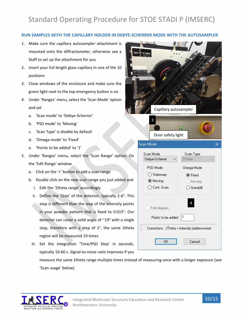
1. Make sure the capillary autosampler attachment is
mounted onto the diffractometer, otherwise see a
Staff to set up the attachment for you
2. Insert your full length glass capillary in one of the 10
positions
3. Close windows of the enclosure and make sure the
green light next to the top emergency button is on
4. Under ‘Ranges’ menu, select the ‘Scan Mode’ option
and set
a. ‘Scan mode’ to ‘Debye-Scherrer’
b. ‘PSD mode’ to ‘Moving’
c. ‘Scan Type’ is disable by default
d. ‘Omega mode’ to ‘Fixed’
e. ‘Points to be added’ to ‘1’
5. Under ‘Ranges’ menu, select the ‘Scan Range’ option. On
the ‘Edit Range’ window
a. Click on the ‘+’ button to add a scan range
b. Double click on the new scan range you just added and
i. Edit the ‘2theta range’ accordingly
ii. Define the ‘Step’ of the detector, typically 2-6º. This
step is different than the step of the intensity points
in your powder pattern that is fixed to 0.015º. Our
detector can cover a solid angle of ~19º with a single
step, therefore with a step of 1º, the same 2theta
region will be measured 19 times
iii. Set the integration ‘Time/PSD Step’ in seconds,
typically 10-60 s. Signal-to-noise ratio improves if you
measure the same 2theta range multiple times instead of measuring once with a longer exposure (see
‘Scan usage’ below)
Capillary autosampler
Door safety light
3
4

Standard Operating Procedure for STOE STADI P (IMSERC)
11/15 Integrated Molecular Structure Education and Research Center Northwestern University
c. Keep adding more ranges according to your needs, e.g., add a range with longer exposure for the high
angle reflections, etc.
6. Under ‘Ranges’ menu, select the ‘Scan Usage’ option
a. Select ‘Multi-sample’ in ‘Scan Usage’
b. Set the total number of samples you have
loaded on the autosampler in ‘Number of
Samples’
c. By default, measurements will be saved in a
series of files having the same filename plus
a unique index number as an extension
whose starting value is set in ‘First File
Number’. If you want to give a unique
filename and assign different ranges to each
measurement, tick the ‘Individual Ranges / Files’ box and click on the ‘Ranges, Files…’ button:
i. Provide a file name for each sample in the autosampler queue
ii. Assign a specific range per sample, in case you have more than one ranges defined in step 4. A range
of ‘0’ will measure all ranges
7. Start the measurement by clicking on ‘Measurement’ under the ‘Measurement’ menu or clicking on the ‘C’
icon
6

Standard Operating Procedure for STOE STADI P (IMSERC)
12/15 Integrated Molecular Structure Education and Research Center Northwestern University
RUN SAMPLES WITH THE PERMANENTLY ALIGNED CAPILLARY HOLDER IN DEBYE-SCHERRER MODE
1. This pre-aligned capillary holder enables the measurement of full length capillaries with a diameter ranging
from 0.3 mm to 1.5 mm without the use of an optical
camera for alignment. Capillary can be spun during
the measurement. Make sure the permanently
aligned capillary autosampler attachment is
mounted onto the diffractometer, otherwise see a
Staff to set up the attachment for you
2. If stage is spinning and/or occupied with a sample
holder, you need to
a. Stop any rotation by turning the ‘Sample spinner’
dial counter-clockwise
b. Remove the capillary and leave it on the sample table outside
the enclosure of the diffractometer
3. Insert your full length glass capillary in the holder and rotate
the ‘Sample spinner’ knob clockwise at a position between
3 and 4 o’clock
4. Close safety windows of the enclosure and make sure the
green light next to the top emergency button is on
5. Under ‘Ranges’ menu, select the ‘Scan Mode’ option and set
a. ‘Scan mode’ to ‘Debye-Scherrer’
b. ‘PSD mode’ to ‘Moving’
c. ‘Scan Type’ is disable by default
d. ‘Omega mode’ to ‘Fixed’
e. ‘Points to be added’ to ‘1’
6. Under ‘Ranges’ menu, select the ‘Scan Range’ option. On
the ‘Edit Range’ window
a. Click on the ‘+’ button to add a scan range
b. Double click on the new scan range you just added and
i. Edit the ‘2theta range’ accordingly
5
Door safety light
4

Standard Operating Procedure for STOE STADI P (IMSERC)
13/15 Integrated Molecular Structure Education and Research Center Northwestern University
ii. Define the ‘Step’ of the detector, typically 2-6º. This step is different than the step of the intensity points
in your powder pattern that is fixed to 0.015º. Our detector can cover a solid angle of ~19º with a single
step, therefore with a step of 1º, the same 2theta region will be measured 19 times
iii. Set the integration ‘Time/PSD Step’ in seconds, typically 20-60 s
c. Keep adding more ranges according to your needs, e.g., add a range with longer exposure for the high
angle reflections, etc.
7. Under ‘Ranges’ menu, select the ‘Scan Usage’ option
a. Select ‘Single Sample’ if you want to measure your sample/scan range only once
b. Select ‘Repetition’ if you want to measure your sample/scan range multiple time for improving the signal-
to-noise ration. You have the option to add a ‘Waiting time’ in case you are interested in a time dependent
measurement, e.g., transformation, decomposition, etc.
8. Start the measurement by clicking on ‘Measurement’ under the ‘Measurement’ menu or clicking on the ‘C’
icon

Standard Operating Procedure for STOE STADI P (IMSERC)
14/15 Integrated Molecular Structure Education and Research Center Northwestern University
PUBLICATION
Experimental Section
Modify the text below according to the setup and conditions you used during the measurement
PXRD data were collected at room temperature on a STOE-STADI-P powder diffractometer equipped with an
asymmetric curved Germanium monochromator (CuKα1 radiation, λ = 1.54056 Å) and one-dimensional silicon
strip detector (MYTHEN2 1K from DECTRIS). The line focused Cu X-ray tube was operated at 40 kV and 40 mA.
Powder was packed in a X (3 or 8 mm metallic mask | capillary) and sandwiched between XXXX (two polyimide or
acetate layers of tape | capillary). Intensity data from YY to ZZ degrees two theta were collected over a period of
XX mins. Instrument was calibrated against a NIST Silicon standard (640d) prior the measurement.
Acknowledgement
Use was made of the IMSERC X-ray Facility at Northwestern University, which has received support from the Soft
and Hybrid Nanotechnology Experimental (SHyNE) Resource (NSF ECCS-1542205); the State of Illinois and
International Institute for Nanotechnology (IIN).

Standard Operating Procedure for STOE STADI P (IMSERC)
15/15 Integrated Molecular Structure Education and Research Center Northwestern University
TROUBLESHOUTING
1. There is no intensity or the diffraction is very weak during collection
a. Verify that all six safety doors are closed and aligned, and the
safety green light is on
b. The sample is heavily absorbing X-rays. Repack the sample and
do not fill-up the masks with material. Use
only a thin layer of powder for heavily
absorbing samples
c. Check the voltage and current settings of
the X-ray generator (middle of the rack with
electronics/controllers). Default operating settings for Cu-
radiation are 40 kV and 40 mA. In case:
o Values on the generator are zero, contact a Staff
o Settings are different than the default values, under the
‘Setup’ menu select ‘Generator’. At the ‘Generator’
window put the default values at the ‘Set to’ fields and
press the ‘Set kV, mA’ button. It takes a few seconds for
the generator to apply the new values
2. Autosampler does not start
a. Verify that the sample spinner dial is rotated all the way clockwise. Panel with the dial
is located on left side of the goniometer
1c
Door safety light
1a
2a