standard model - grundfos
TRANSCRIPT

CR, CRI, CRN 32-90 Model BStandard model
Service instructions
GRUNDFOS INSTRUCTIONS

En
glis
h (G
B)
English (GB) Service instructions
Original service instructions.
CONTENTSPage
1. Symbols used in this document
2. General informationPosition numbers of parts (digits) refer to drawings and parts lists; position numbers of tools (letters) refer to section 3. Service tools.
Before dismantling
• Close the isolating valves, if fitted, and make sure that they cannot be accidentally opened.
• Before starting work on the product, let the product and pumped liquid cool off.
Before assembly
• Clean and check all parts.
• Replace defective parts with new parts.
• Always replace gaskets and O-rings.
During assembly
• Tighten screws and nuts according to section 4. Torques.
• Lubricate rings and screws according to section 5. Lubricants.
After assembly
• If analog or digital inputs, the relay output or the CIM module has been removed from the pump, you must check the communication with external units after service.
1. Symbols used in this document 2
2. General information 2
3. Service tools 3
4. Torques 4
5. Lubricants 4
6. Pump dismantling 46.1 Motor 46.2 Shaft seal and pump head 46.3 Chamber stack 5
7. Checking chamber parts 6
8. Replacing chamber parts 68.1 Complete neck ring (pos. 45a) 68.2 Wear ring (pos. 49c) 78.3 Bush (pos. 47c) and retaining ring (pos. 47d) 7
9. Pump assembly 79.1 Chamber stack 79.2 Pump head and shaft seal 89.3 Motor 9
10. Order of assembly for chambers and impellers 1010.1 CR, CRI, CRN 32 1010.2 CR, CRI, CRN 45 1010.3 CR, CRI, CRN 64 1110.4 CR, CRI, CRN 90 11
11. Exploded views 12
Warning
Prior to service work, read these service instructions carefully. Installation and service work must comply with local regulations and accepted codes of good practice.
Observe the safety instructions in the installation and operating instructions for the product.
Warning
If these safety instructions are not observed, it may result in personal injury.
Warning
If these instructions are not observed, it may lead to electric shock with consequent risk of serious personal injury or death.
CautionIf these safety instructions are not observed, it may result in malfunction or damage to the equipment.
NoteNotes or instructions that make the job easier and ensure safe operation.
Warning
If there is a risk of getting into contact with the pumped liquid, use personal protective equipment.
Observe local regulations.
Warning
Switch off the power supply and make sure that it cannot be accidentally switched on.
Check that other pumps or sources do not force flow through the pump even if the pump is stopped. This will cause the motor to act like a generator, resulting in voltage on the pump.
2
En
gli
sh
(G
B)
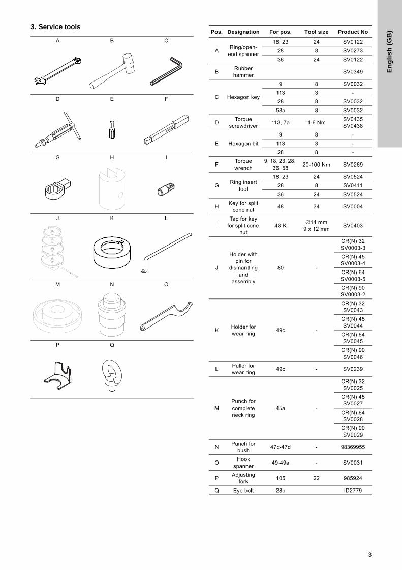
3. Service toolsA B C
D E F
G H I
J K L
M N O
P Q
Pos. Designation For pos. Tool size Product No
ARing/open-
end spanner
18, 23 24 SV0122
28 8 SV0273
36 24 SV0122
BRubber hammer
SV0349
C Hexagon key
9 8 SV0032
113 3 -
28 8 SV0032
58a 8 SV0032
DTorque
screwdriver113, 7a 1-6 Nm
SV0435SV0438
E Hexagon bit
9 8 -
113 3 -
28 8 -
FTorque wrench
9, 18, 23, 28, 36, 58
20-100 Nm SV0269
GRing insert
tool
18, 23 24 SV0524
28 8 SV0411
36 24 SV0524
HKey for split
cone nut48 34 SV0004
ITap for key
for split cone nut
48-K14 mm
9 x 12 mmSV0403
J
Holder with pin for
dismantling and
assembly
80 -
CR(N) 32 SV0003-3
CR(N) 45 SV0003-4
CR(N) 64 SV0003-5
CR(N) 90 SV0003-2
KHolder for wear ring
49c -
CR(N) 32 SV0043
CR(N) 45 SV0044
CR(N) 64 SV0045
CR(N) 90 SV0046
LPuller for wear ring
49c - SV0239
MPunch for complete neck ring
45a -
CR(N) 32 SV0025
CR(N) 45 SV0027
CR(N) 64 SV0028
CR(N) 90 SV0029
NPunch for
bush47c-47d - 98369955
OHook
spanner49-49a - SV0031
PAdjusting
fork105 22 985924
Q Eye bolt 28b ID2779
3
En
glis
h (G
B)
4. Torques
5. Lubricants
6. Pump dismantlingPosition numbers refer to the drawings in section 11. Exploded views.
6.1 Motor
1. Remove screws (pos. 7a) and coupling guards (pos. 7).
2. Remove screws (pos. 9) and coupling (pos. 8). It may be necessary to loosen the coupling with a rubber hammer.
3. Attach lifting device to eyebolts (pos. 28b).
4. Remove screws (pos. 28). Lift and remove motor and motor stool (pos. 1a).
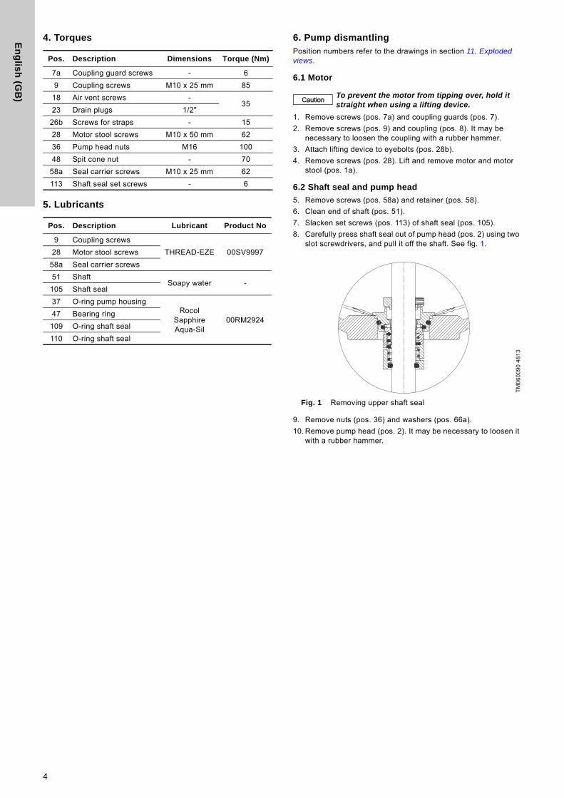
6.2 Shaft seal and pump head
5. Remove screws (pos. 58a) and retainer (pos. 58).
6. Clean end of shaft (pos. 51).
7. Slacken set screws (pos. 113) of shaft seal (pos. 105).
8. Carefully press shaft seal out of pump head (pos. 2) using two slot screwdrivers, and pull it off the shaft. See fig. 1.
Fig. 1 Removing upper shaft seal
9. Remove nuts (pos. 36) and washers (pos. 66a).
10. Remove pump head (pos. 2). It may be necessary to loosen it with a rubber hammer.
Pos. Description Dimensions Torque (Nm)
7a Coupling guard screws - 6
9 Coupling screws M10 x 25 mm 85
18 Air vent screws -35
23 Drain plugs 1/2"
26b Screws for straps - 15
28 Motor stool screws M10 x 50 mm 62
36 Pump head nuts M16 100
48 Spit cone nut - 70
58a Seal carrier screws M10 x 25 mm 62
113 Shaft seal set screws - 6
Pos. Description Lubricant Product No
9 Coupling screws
THREAD-EZE 00SV999728 Motor stool screws
58a Seal carrier screws
51 ShaftSoapy water -
105 Shaft seal
37 O-ring pump housingRocol
Sapphire Aqua-Sil
00RM292447 Bearing ring
109 O-ring shaft seal
110 O-ring shaft seal
Caution To prevent the motor from tipping over, hold it straight when using a lifting device.
TM
06
00
90
48
13
4

En
gli
sh
(G
B)
6.3 Chamber stack
6.3.1 Fitting chamber stack on the holder
11. Place the holder for dismantling and assembly in a vice and tighten it. See fig. 2 for right positioning.
12. Pull the chamber stack out of the outer sleeves (pos. 55) and place it in the holder according to fig. 2. Make sure the chamber stack engages with the holder.
13. Fit the locking pin in the hole marked "Dismantling".
Fig. 2 Positioning the chamber stack in the holder
14. Remove screws (pos. 26b) and washers (pos. 26c).
15. Remove straps (pos. 26a).
6.3.2 Dismantling chambers
Depending on their construction, dismantle the chambers according to the instructions below. The symbols refer to section 10. Order of assembly for chambers and impellers.
Single chamber
Fig. 3 Single chamber
1. Pull apart the rotating spring of the bearing (pos. 47a) and remove the bearing.
2. Hold impeller (pos. 49) with the hook spanner, and slacken split cone nut (pos. 48) using the key for split cone nut. Knock the nut to loosen the impeller from the split cone (pos. 49b).
3. Pull the split cone nut, split cone and impeller off the shaft.
Top chamber and chamber without bearing
Fig. 4 Left: top chamber; right: chamber without bearing
1. Loosen chamber (pos. 3) from the chamber below using a screwdriver, and remove it.
2. Hold impeller (pos. 49) with the hook spanner, and slacken split cone nut (pos. 48) using the key for split cone nut. Turn the key around, and knock the nut to loosen the impeller from split cone (pos. 49b).
3. Pull the split cone nut, split cone and impeller off the shaft.
Chamber with bearing
Fig. 5 Chamber with bearing
1. Loosen chamber (pos. 4a) from the chamber below or inlet part (pos.44) using a screwdriver.
2. Loosen bearing ring (pos. 47a) from split cone nut (pos. 48) and pull it off the shaft.
3. Hold impeller (pos. 49) with the hook spanner, and slacken split cone nut (pos. 48) using the key for split cone nut. Turn the key around, and knock the nut to loosen the impeller from split cone (pos. 49b).
4. Pull the split cone nut, split cone and impeller off the shaft.
5. When the last impeller has been removed, inlet part (pos. 44) can be lifted off the holder.
TM
06
01
80
50
13
5

En
glis
h (G
B)
7. Checking chamber partsPosition numbers refer to the drawings in section 11. Exploded views.
Check the distance between parts 1 and 2. See the table below. If the distance is superior to the maximum tolerance indicated, replace the parts.
Fig. 6 Tolerance between bush and shaft
Fig. 7 Tolerance between bearing ring and driver
8. Replacing chamber partsPosition numbers refer to the drawings in section 11. Exploded views.
8.1 Complete neck ring (pos. 45a)
8.1.1 Dismantling
1. Push the complete neck ring up and free from chamber (pos. 4/4a) or inlet part (pos. 44) using a screwdriver. See fig. 8.
Fig. 8 Removing complete neck ring
2. Push neck ring retainer (pos. 65) up and free from cup (pos. 46) using a screwdriver, and remove neck ring (pos. 45). See fig. 9.
Fig. 9 Removing neck ring
Fig.Part 1 Part 2 Max.
tolerance [mm]Pos. Description Pos. Description
6 47c Bush 51 Shaft 1.0
7 47 Bearing ring 47a Driver 0.3
TM
06
05
90
05
14
TM
06
05
89
05
14
TM
06
08
08
10
14
TM
06
08
09
10
14
6

En
gli
sh
(G
B)
8.1.2 Assembly
1. Place neck ring (pos. 45) in cup (pos. 46).
2. Fit neck ring retainer (pos. 65) with the four driving dogs pointing downwards. Turn the neck ring retainer until it engages with the neck ring.
3. Knock/press the neck ring retainer home against the cup using the punch for complete neck ring. Check that the measurement is within the tolerance range. See fig. 10.
Fig. 10 Measure distance between retainer and top of cup
4. Fit the complete neck ring in chamber (pos. 4/4a) or inlet part (pos. 44) and knock/press it home using the punch for complete neck ring.
8.2 Wear ring (pos. 49c)
8.2.1 Dismantling
1. Fit the holder on the impeller. The wear ring should come out in the centre of the holder. See fig 11.
2. Place the impeller and holder on a flat surface, the wear ring uppermost.
3. Push the wear ring up and free of the impeller using the puller. See fig. 11.
Fig. 11 Removing wear ring
8.2.2 Assembly
Press wear ring (pos. 49c) carefully down over impeller skirt (pos. 49/49a).
8.3 Bush (pos. 47c) and retaining ring (pos. 47d)
8.3.1 Dismantling
Place the chamber on a flat surface, and press the bush and retaining ring down using the punch for bush.
8.3.2 Assembly
Place the chamber on a level and solid surface with complete neck ring (pos. 45a) facing downwards, and press the bush and retaining ring home against the chamber using the punch for bush.
9. Pump assemblyPosition numbers refer to the drawings in section 11. Exploded views.
9.1 Chamber stack
9.1.1 Fitting the inlet part
1. Place the holder for dismantling and assembly in a vice and tighten it.
2. Place the shaft and inlet part (pos. 44) in the holder according to fig. 12. Make sure that the inlet part engages with the holder.
Fig. 12 Placing the shaft and inlet part in the holder
3. Fit the locking pin in the hole marked "Assembly".
1. Fit impeller (pos. 49) onto the shaft and press it home in the inlet part.
2. Fit split cone (pos. 49b) and knock it into the impeller hub using the key for split cone nut.
3. Hold the impeller with the hook spanner and tighten split cone nut (pos. 48).
4. Remove the shaft from the holder and check that the impeller flushes with the shaft groove. See fig. 13.
Fig. 13 Checking that the impeller flushes with the shaft groove
5. Refit the shaft in the holder, and fit the locking pin in the "Assembly" hole.
TM
011
95
5 2
20
1
Pump Nominal height, X [mm] Tolerance range [mm]
CR(N) 32 10.1
± 0.2CR(N) 45 15.5
CR(N) 64 11.5
CR(N) 90 12.1
NoteIt should be possible to move the neck ring freely (sideways) between the neck ring retainer and the cup.
TM
00
72
33
09
96
CautionMake sure to push the ring straight down against the impeller skirt. Make sure not to damage the impeller.
XX
TM
06
05
74
05
14
7

En
glis
h (G
B)
9.1.2 Assembling chambers
Depending on their construction, dismantle the chambers according to the instructions below. The symbols refer to section 10. Order of assembly for chambers and impellers.
Chamber without bearing
Fig. 14 Chamber without bearing
1. Fit impeller (pos. 49) and press it home.
2. Fit split cone (pos. 49b) and knock it into the impeller hub using the key for split cone nut.
3. Hold the impeller with the hook spanner. Fit and tighten split cone nut (pos. 48).
4. Fit chamber (pos. 4a) and press it home against the chamber below.
Chamber with bearing
Fig. 15 Chamber with bearing
1. Fit impeller (pos. 49) and press it home.
2. Fit split cone (pos. 49b) and knock it into the impeller hub using the key for split cone nut.
3. Hold the impeller with the hook spanner. Fit and tighten split cone nut (pos. 48).
4. Slide bearing ring (pos. 47a) over the split cone nut. It must engage with the split cone nut.
5. Fit chamber (pos. 4a) and press it home against the chamber below or inlet part (pos. 44).
Top chamber
Fig. 16 Top chamber
1. Fit impeller (pos. 49) and press it home.
2. Fit split cone (pos. 49b) and knock it into the impeller hub using the key for split cone nut.
3. Hold the impeller with the hook spanner. Fit and tighten split cone nut (pos. 48).
4. Fit chamber (pos. 3a). Turn it so that the holes for straps are aligned to the fixing lugs for straps on the inlet part.
5. Press the chamber home against the chamber below.
6. Fit straps (pos. 26a), washers (pos. 26c), and cross-tighten screws (pos. 26b).
Single chamber
Fig. 17 Single chamber
1. Fit impeller (pos. 49) and press it home.
2. Fit split cone (pos. 49b) and knock it into the impeller hub using the key for split cone nut.
3. Hold the impeller with the hook spanner. Fit and tighten split cone nut (pos. 48).
4. Slide bearing ring (pos. 47a) over the split cone nut. It must engage with the split cone nut.
5. Fit chamber (pos. 3). Turn it so that the holes for straps are aligned to the fixing lugs for straps on the inlet part.
6. Press the chamber home against inlet part (pos. 44).
7. Fit straps (pos. 26a) and washers (pos. 26c), and cross-tighten screws (pos. 26b).
9.2 Pump head and shaft seal
1. Replace rubber springs (pos. 60) and O-ring (pos. 37).
2. Fit pump head (pos. 2) on outer sleeves (pos. 55).
3. Fit washers (pos. 66a) and cross-tighten nuts (36).
4. Carefully press shaft seal (pos. 105) down the shaft and in the pump head.
5. Fit retainer (pos. 58) and cross-tighten screws (58a).
6. Press the pump shaft home and tighten set screws (pos. 113).
7. Lift the pump shaft and insert the adjusting fork between the shaft seal driver and its retainer. See fig. 18.
Fig. 18 Fitting adjusting forks
NoteMount the reduced impeller(s), if any, last in the top chamber(s).
CautionBe careful when pressing the chambers down the shaft. The bearings are fragile and cannot stand blows or contact with the shafts.
TM
06
00
71
48
13
8

En
gli
sh
(G
B)
9.3 Motor
1. Attach the lifting device to the eyebolts. Lift and fit the motor and motor stool on upper pump head (pos. 2).
2. Cross-tighten screws (pos. 28).
3. Fit coupling (pos. 8), according to fig. 19 and 20, and tighten screws (pos. 9).
Fig. 19 Fitting coupling
Fig. 20 Adjusting coupling
4. Remove the adjusting fork, and place it under one of screws (pos. 58a).
5. Check that the pump shaft can rotate freely.
6. Fit coupling guards (pos. 7) and screws (pos. 7a).
Caution To prevent the motor from tipping over, hold it straight when using a lifting device.
TM
05
75
78
12
13
TM
03
96
07
42
07
9

En
glis
h (G
B)
10. Order of assembly for chambers and impellersThe assembly of the pump is illustrated in the following drawings. Each symbol corresponds to a different chamber.
10.1 CR, CRI, CRN 32
10.2 CR, CRI, CRN 45
Note Pos. 49 is the standard size impeller. Pos. 49a is a reduced impeller (2/3 of standard size).
TM
05
99
93
46
13
3456
21
7891011121314
7
12
6543
TM
05
99
94
46
13
3456
21
78910111213
7
12
6543
10

En
gli
sh
(G
B)
10.3 CR, CRI, CRN 64
10.4 CR, CRI, CRN 90
TM
05
99
95
46
13
3456
21
87
TM
05
99
96
46
13
3456
21
11

En
glis
h (G
B)
11. Exploded views
Fig. 21 Exploded view, CR, CRI, CRN 32, model B
TM
05
84
05
23
13
12

En
gli
sh
(G
B)
Fig. 22 Exploded view (detailed), CR, CRI, CRN 32, model B
Subject to alterations.
TM
06
05
70
05
14
13

14

Gru
nd
fos
co
mp
anie
s
ArgentinaBombas GRUNDFOS de Argentina S.A.Ruta Panamericana km. 37.500 Centro Industrial Garin1619 Garín Pcia. de B.A.Phone: +54-3327 414 444Telefax: +54-3327 45 3190
AustraliaGRUNDFOS Pumps Pty. Ltd. P.O. Box 2040 Regency Park South Australia 5942 Phone: +61-8-8461-4611 Telefax: +61-8-8340 0155
AustriaGRUNDFOS Pumpen Vertrieb Ges.m.b.H.Grundfosstraße 2 A-5082 Grödig/Salzburg Tel.: +43-6246-883-0 Telefax: +43-6246-883-30
BelgiumN.V. GRUNDFOS Bellux S.A. Boomsesteenweg 81-83 B-2630 Aartselaar Tél.: +32-3-870 7300 Télécopie: +32-3-870 7301
BelarusПредставительство ГРУНДФОС в Минске220125, Минскул. Шафарнянская, 11, оф. 56, БЦ «Порт»Тел.: +7 (375 17) 286 39 72/73Факс: +7 (375 17) 286 39 71E-mail: [email protected]
Bosna and HerzegovinaGRUNDFOS SarajevoZmaja od Bosne 7-7A,BH-71000 SarajevoPhone: +387 33 592 480Telefax: +387 33 590 465www.ba.grundfos.come-mail: [email protected]
BrazilBOMBAS GRUNDFOS DO BRASILAv. Humberto de Alencar Castelo Branco, 630CEP 09850 - 300São Bernardo do Campo - SPPhone: +55-11 4393 5533Telefax: +55-11 4343 5015
BulgariaGrundfos Bulgaria EOODSlatina DistrictIztochna Tangenta street no. 100BG - 1592 SofiaTel. +359 2 49 22 200Fax. +359 2 49 22 201email: [email protected]
CanadaGRUNDFOS Canada Inc. 2941 Brighton Road Oakville, Ontario L6H 6C9 Phone: +1-905 829 9533 Telefax: +1-905 829 9512
ChinaGRUNDFOS Pumps (Shanghai) Co. Ltd.10F The Hub, No. 33 Suhong RoadMinhang DistrictShanghai 201106PRCPhone: +86 21 612 252 22Telefax: +86 21 612 253 33
CroatiaGRUNDFOS CROATIA d.o.o.Buzinski prilaz 38, BuzinHR-10010 ZagrebPhone: +385 1 6595 400 Telefax: +385 1 6595 499www.hr.grundfos.com
Czech RepublicGRUNDFOS s.r.o.Čajkovského 21779 00 OlomoucPhone: +420-585-716 111Telefax: +420-585-716 299
DenmarkGRUNDFOS DK A/S Martin Bachs Vej 3 DK-8850 Bjerringbro Tlf.: +45-87 50 50 50 Telefax: +45-87 50 51 51 E-mail: [email protected]/DK
EstoniaGRUNDFOS Pumps Eesti OÜPeterburi tee 92G11415 TallinnTel: + 372 606 1690Fax: + 372 606 1691
FinlandOY GRUNDFOS Pumput AB Mestarintie 11 FIN-01730 Vantaa Phone: +358-(0)207 889 900Telefax: +358-(0)207 889 550
FrancePompes GRUNDFOS Distribution S.A. Parc d’Activités de Chesnes 57, rue de Malacombe F-38290 St. Quentin Fallavier (Lyon) Tél.: +33-4 74 82 15 15 Télécopie: +33-4 74 94 10 51
GermanyGRUNDFOS GMBHSchlüterstr. 3340699 ErkrathTel.: +49-(0) 211 929 69-0 Telefax: +49-(0) 211 929 69-3799e-mail: [email protected] in Deutschland:e-mail: [email protected]
HILGE GmbH & Co. KGHilgestrasse 37-4755292 Bodenheim/RheinGermanyTel.: +49 6135 75-0Telefax: +49 6135 1737e-mail: [email protected]
GreeceGRUNDFOS Hellas A.E.B.E. 20th km. Athinon-Markopoulou Av. P.O. Box 71 GR-19002 Peania Phone: +0030-210-66 83 400 Telefax: +0030-210-66 46 273
Hong KongGRUNDFOS Pumps (Hong Kong) Ltd. Unit 1, Ground floor Siu Wai Industrial Centre 29-33 Wing Hong Street & 68 King Lam Street, Cheung Sha Wan Kowloon Phone: +852-27861706 / 27861741 Telefax: +852-27858664
HungaryGRUNDFOS Hungária Kft.Park u. 8H-2045 Törökbálint, Phone: +36-23 511 110Telefax: +36-23 511 111
IndiaGRUNDFOS Pumps India Private Limited118 Old Mahabalipuram RoadThoraipakkamChennai 600 096Phone: +91-44 2496 6800
IndonesiaPT. GRUNDFOS POMPAGraha Intirub Lt. 2 & 3Jln. Cililitan Besar No.454. Makasar, Jakarta TimurID-Jakarta 13650Phone: +62 21-469-51900Telefax: +62 21-460 6910 / 460 6901
IrelandGRUNDFOS (Ireland) Ltd. Unit A, Merrywell Business ParkBallymount Road LowerDublin 12 Phone: +353-1-4089 800 Telefax: +353-1-4089 830
ItalyGRUNDFOS Pompe Italia S.r.l. Via Gran Sasso 4I-20060 Truccazzano (Milano)Tel.: +39-02-95838112 Telefax: +39-02-95309290 / 95838461
JapanGRUNDFOS Pumps K.K.Gotanda Metalion Bldg., 5F, 5-21-15, Higashi-gotandaShiagawa-ku, Tokyo141-0022 JapanPhone: +81 35 448 1391Telefax: +81 35 448 9619
KoreaGRUNDFOS Pumps Korea Ltd.6th Floor, Aju Building 679-5Yeoksam-dong, Kangnam-ku, 135-916Seoul, KoreaPhone: +82-2-5317 600Telefax: +82-2-5633 725
LatviaSIA GRUNDFOS Pumps Latvia Deglava biznesa centrsAugusta Deglava ielā 60, LV-1035, Rīga,Tālr.: + 371 714 9640, 7 149 641Fakss: + 371 914 9646
LithuaniaGRUNDFOS Pumps UABSmolensko g. 6LT-03201 VilniusTel: + 370 52 395 430Fax: + 370 52 395 431
MalaysiaGRUNDFOS Pumps Sdn. Bhd.7 Jalan Peguam U1/25Glenmarie Industrial Park40150 Shah AlamSelangor Phone: +60-3-5569 2922Telefax: +60-3-5569 2866
MexicoBombas GRUNDFOS de México S.A. de C.V. Boulevard TLC No. 15Parque Industrial Stiva AeropuertoApodaca, N.L. 66600Phone: +52-81-8144 4000 Telefax: +52-81-8144 4010
NetherlandsGRUNDFOS NetherlandsVeluwezoom 351326 AE AlmerePostbus 220151302 CA ALMERE Tel.: +31-88-478 6336 Telefax: +31-88-478 6332E-mail: [email protected]
New ZealandGRUNDFOS Pumps NZ Ltd.17 Beatrice Tinsley CrescentNorth Harbour Industrial EstateAlbany, AucklandPhone: +64-9-415 3240Telefax: +64-9-415 3250
NorwayGRUNDFOS Pumper A/S Strømsveien 344 Postboks 235, Leirdal N-1011 Oslo Tlf.: +47-22 90 47 00 Telefax: +47-22 32 21 50
PolandGRUNDFOS Pompy Sp. z o.o.ul. Klonowa 23Baranowo k. PoznaniaPL-62-081 PrzeźmierowoTel: (+48-61) 650 13 00Fax: (+48-61) 650 13 50
PortugalBombas GRUNDFOS Portugal, S.A. Rua Calvet de Magalhães, 241Apartado 1079P-2770-153 Paço de ArcosTel.: +351-21-440 76 00Telefax: +351-21-440 76 90
RomaniaGRUNDFOS Pompe România SRLBd. Biruintei, nr 103 Pantelimon county IlfovPhone: +40 21 200 4100Telefax: +40 21 200 4101E-mail: [email protected]
RussiaООО Грундфос Россия109544, г. Москва, ул. Школьная, 39-41, стр. 1Тел. (+7) 495 564-88-00 (495) 737-30-00Факс (+7) 495 564 88 11E-mail [email protected]
Serbia Grundfos Srbija d.o.o.Omladinskih brigada 90b11070 Novi Beograd Phone: +381 11 2258 740Telefax: +381 11 2281 769www.rs.grundfos.com
SingaporeGRUNDFOS (Singapore) Pte. Ltd.25 Jalan Tukang Singapore 619264 Phone: +65-6681 9688 Telefax: +65-6681 9689
SlovakiaGRUNDFOS s.r.o.Prievozská 4D 821 09 BRATISLAVA Phona: +421 2 5020 1426sk.grundfos.com
SloveniaGRUNDFOS d.o.o.Šlandrova 8b, SI-1231 Ljubljana-ČrnučePhone: +386 31 718 808Telefax: +386 (0)1 5680 619E-mail: [email protected]
South AfricaGRUNDFOS (PTY) LTDCorner Mountjoy and George Allen RoadsWilbart Ext. 2Bedfordview 2008Phone: (+27) 11 579 4800Fax: (+27) 11 455 6066E-mail: [email protected]
SpainBombas GRUNDFOS España S.A. Camino de la Fuentecilla, s/n E-28110 Algete (Madrid) Tel.: +34-91-848 8800 Telefax: +34-91-628 0465
SwedenGRUNDFOS AB Box 333 (Lunnagårdsgatan 6) 431 24 Mölndal Tel.: +46 31 332 23 000Telefax: +46 31 331 94 60
SwitzerlandGRUNDFOS Pumpen AG Bruggacherstrasse 10 CH-8117 Fällanden/ZH Tel.: +41-44-806 8111 Telefax: +41-44-806 8115
TaiwanGRUNDFOS Pumps (Taiwan) Ltd. 7 Floor, 219 Min-Chuan Road Taichung, Taiwan, R.O.C. Phone: +886-4-2305 0868Telefax: +886-4-2305 0878
ThailandGRUNDFOS (Thailand) Ltd. 92 Chaloem Phrakiat Rama 9 Road,Dokmai, Pravej, Bangkok 10250Phone: +66-2-725 8999Telefax: +66-2-725 8998
TurkeyGRUNDFOS POMPA San. ve Tic. Ltd. Sti.Gebze Organize Sanayi Bölgesi Ihsan dede Caddesi,2. yol 200. Sokak No. 20441490 Gebze/ KocaeliPhone: +90 - 262-679 7979Telefax: +90 - 262-679 7905E-mail: [email protected]
UkraineБізнес Центр ЄвропаСтоличне шосе, 103м. Київ, 03131, Україна Телефон: (+38 044) 237 04 00 Факс.: (+38 044) 237 04 01E-mail: [email protected]
United Arab EmiratesGRUNDFOS Gulf DistributionP.O. Box 16768Jebel Ali Free ZoneDubaiPhone: +971 4 8815 166Telefax: +971 4 8815 136
United KingdomGRUNDFOS Pumps Ltd. Grovebury Road Leighton Buzzard/Beds. LU7 4TL Phone: +44-1525-850000 Telefax: +44-1525-850011
U.S.A.GRUNDFOS Pumps Corporation 17100 West 118th TerraceOlathe, Kansas 66061Phone: +1-913-227-3400 Telefax: +1-913-227-3500
UzbekistanGrundfos Tashkent, Uzbekistan The Repre-sentative Office of Grundfos Kazakhstan in Uzbekistan38a, Oybek street, TashkentТелефон: (+998) 71 150 3290 / 71 150 3291Факс: (+998) 71 150 3292
Addresses Revised 10.03.2015
98642944 0815
ECM: 1164802 The
nam
e G
rund
fos,
the
Gru
ndfo
s lo
go, a
nd b
e t
hin
k i
nn
ov
ate
are
regi
ster
ed tr
adem
arks
ow
ned
by G
rund
fos
Hol
ding
A/S
or G
rund
fos
A/S,
Den
mar
k. A
ll rig
hts
rese
rved
wor
ldw
ide.
© C
opyr
ight
Gru
ndfo
s H
oldi
ng A
/S
www.grundfos.com