standard for water mist fire protection systems b 813, standard specification for liquid and paste...
TRANSCRIPT

Copyright © National Fire Protection Association 2013 . All rights reserved. This copy is solely for your personal, noncommercial use in connection with participation in the NFPA Standards Development Process. Except for limited hard copies reasonably necessary for such use, this copy may not be reproduced or redistributed. For additional copies of this and other downloadable reports related to the NFPA Standards Development Process visit www.nfpa.org.
1 Balloting Version: First Draft Proposed 2014 Edition NFPA 750
Balloting Version First Draft NFPA® 750 Standard for
Water Mist Fire Protection Systems
Proposed 2014 Edition
About This Document: This document is the Balloting Version of the First Draft of the proposed 2014 edition of NFPA 750. It has been compiled by NFPA staff for the purpose of balloting by the responsible Technical Committee(s) in accordance with the Regulations Governing the Development of NFPA Standards ("Regs.") This Balloting Version of the First Draft incorporates the changes made through First Revisions developed by the Technical Committee at its First Draft Meeting, and it is made available to Technical Committee members for their review during balloting. Only First Revisions that Pass the Technical Committee ballot will be included in the Final First Draft that will be published for public review. See, generally, Regs. at Section 4.3, Committee Activities: Input Stage.
Chapter 1 Administration 1.1* Scope. This standard contains the minimum requirements for the design, installation, maintenance, and testing of water mist fire protection systems. This standard does not provide definitive fire performance criteria, nor does it offer specific guidance on how to design a system to control, suppress, or extinguish a fire. Reliance is placed on the procurement and installation of listed

2 Balloting Version: First Draft Proposed 2014 Edition NFPA 750
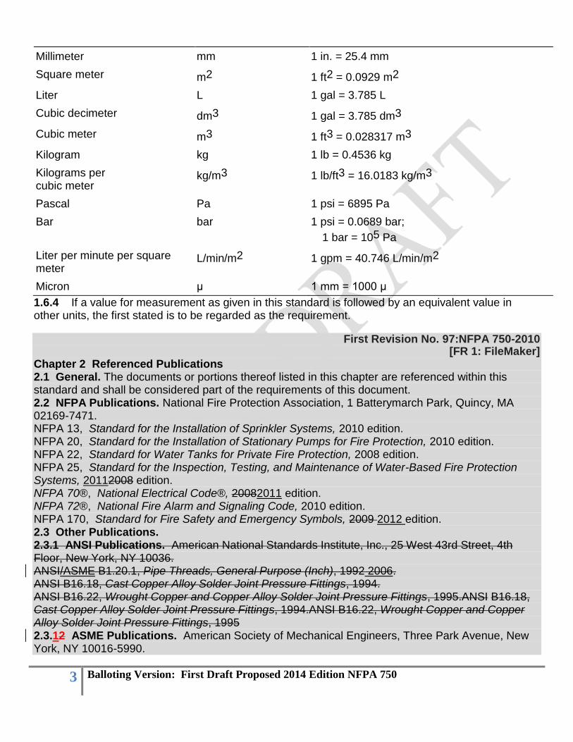
water mist equipment or systems that have demonstrated performance in fire tests as part of a listing process. 1.2* Purpose. 1.2.1 The purpose of this standard is to provide protection for life and property from fire through the standardization of design, installation, maintenance, and testing requirements for water-based fire suppression systems that use a specific spray (mist) that absorbs heat, displaces oxygen, or blocks radiant heat to control, suppress, or extinguish fires as required by the application. 1.2.2 The user of this standard shall recognize the complexity of water mist fire suppression systems. Therefore, the designer shall be cautioned that the standard is not a design handbook. The standard shall not do away with the need for the engineer or for competent engineering judgment. It is the intent that a designer capable of applying more complete and rigorous analysis to special or unusual problems shall have latitude in the development of such designs. In such cases, the designer shall be responsible for demonstrating the validity of the design approach. 1.3 Application. This standard shall apply to water mist fire protection systems and shall establish minimum requirements for water mist technology on the basis of sound engineering principles, test data, and field experience. 1.4 Retroactivity. The provisions of this standard reflect a consensus of what is necessary to provide an acceptable degree of protection from the hazards addressed in this standard at the time the standard was issued. 1.4.1 Unless otherwise specified, the provisions of this standard shall not apply to facilities, equipment, structures, or installations that existed or were approved for construction or installation prior to the effective date of the standard. Where specified, the provisions of this standard shall be retroactive. 1.4.2 In those cases where the authority having jurisdiction determines that the existing situation presents an unacceptable degree of risk, the authority having jurisdiction shall be permitted to apply retroactively any portions of this standard deemed appropriate. 1.4.3 The retroactive requirements of this standard shall be permitted to be modified if their application clearly would be impractical in the judgment of the authority having jurisdiction, and only where it is clearly evident that a reasonable degree of safety is provided. 1.5 Equivalency. Nothing in this standard is intended to prevent the use of systems, methods, or devices of equivalent or superior quality, strength, fire resistance, effectiveness, durability, and safety over those prescribed by this standard. 1.5.1 Technical documentation shall be submitted to the authority having jurisdiction to demonstrate equivalency. 1.5.2 The system, method, or device shall be approved for the intended purpose by the authority having jurisdiction. 1.6* Units. 1.6.1 Metric units of measurement in this standard are in accordance with the modernized metric system known as the International System of Units (SI). 1.6.2 Two units (liter and bar) outside of but recognized by SI are commonly used in international fire protection. 1.6.3 These units are listed in Table 1.6.3 with conversion factors.
Table 1.6.3 Metric Conversion Factors
Name of Unit Unit Abbreviation or
Symbol Conversion Factor
3 Balloting Version: First Draft Proposed 2014 Edition NFPA 750
Millimeter mm 1 in. = 25.4 mm
Square meter m2 1 ft2 = 0.0929 m2
Liter L 1 gal = 3.785 L
Cubic decimeter dm3 1 gal = 3.785 dm3
Cubic meter m3 1 ft3 = 0.028317 m3
Kilogram kg 1 lb = 0.4536 kg
Kilograms per cubic meter
kg/m3 1 lb/ft3 = 16.0183 kg/m3
Pascal Pa 1 psi = 6895 Pa
Bar bar 1 psi = 0.0689 bar;
1 bar = 105 Pa
Liter per minute per square meter
L/min/m2 1 gpm = 40.746 L/min/m2
Micron μ 1 mm = 1000 μ
1.6.4 If a value for measurement as given in this standard is followed by an equivalent value in other units, the first stated is to be regarded as the requirement.
First Revision No. 97:NFPA 750-2010 [FR 1: FileMaker]
Chapter 2 Referenced Publications 2.1 General. The documents or portions thereof listed in this chapter are referenced within this standard and shall be considered part of the requirements of this document. 2.2 NFPA Publications. National Fire Protection Association, 1 Batterymarch Park, Quincy, MA 02169-7471. NFPA 13, Standard for the Installation of Sprinkler Systems, 2010 edition. NFPA 20, Standard for the Installation of Stationary Pumps for Fire Protection, 2010 edition. NFPA 22, Standard for Water Tanks for Private Fire Protection, 2008 edition. NFPA 25, Standard for the Inspection, Testing, and Maintenance of Water-Based Fire Protection Systems, 20112008 edition. NFPA 70®, National Electrical Code®, 20082011 edition. NFPA 72®, National Fire Alarm and Signaling Code, 2010 edition. NFPA 170, Standard for Fire Safety and Emergency Symbols, 2009 2012 edition. 2.3 Other Publications. 2.3.1 ANSI Publications. American National Standards Institute, Inc., 25 West 43rd Street, 4th Floor, New York, NY 10036. ANSI/ASME B1.20.1, Pipe Threads, General Purpose (Inch), 1992 2006. ANSI B16.18, Cast Copper Alloy Solder Joint Pressure Fittings, 1994. ANSI B16.22, Wrought Copper and Copper Alloy Solder Joint Pressure Fittings, 1995.ANSI B16.18, Cast Copper Alloy Solder Joint Pressure Fittings, 1994.ANSI B16.22, Wrought Copper and Copper Alloy Solder Joint Pressure Fittings, 1995 2.3.12 ASME Publications. American Society of Mechanical Engineers, Three Park Avenue, New York, NY 10016-5990.
4 Balloting Version: First Draft Proposed 2014 Edition NFPA 750
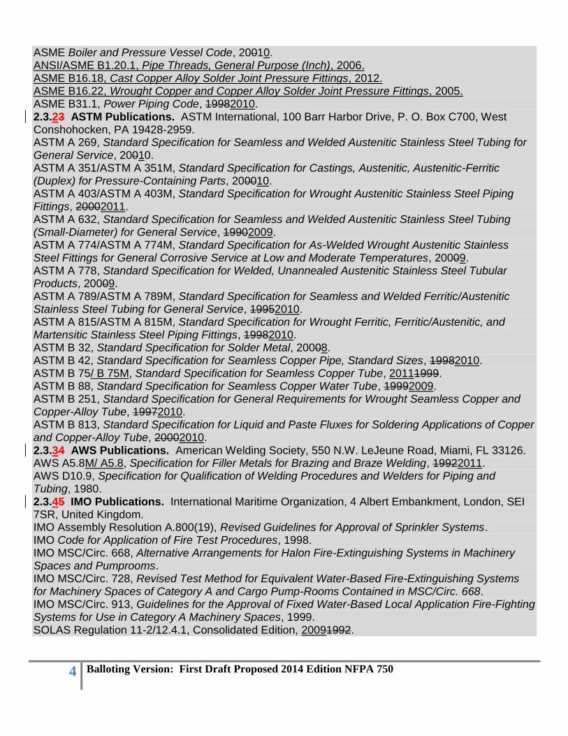
ASME Boiler and Pressure Vessel Code, 20010. ANSI/ASME B1.20.1, Pipe Threads, General Purpose (Inch), 2006. ASME B16.18, Cast Copper Alloy Solder Joint Pressure Fittings, 2012. ASME B16.22, Wrought Copper and Copper Alloy Solder Joint Pressure Fittings, 2005. ASME B31.1, Power Piping Code, 19982010. 2.3.23 ASTM Publications. ASTM International, 100 Barr Harbor Drive, P. O. Box C700, West Conshohocken, PA 19428-2959. ASTM A 269, Standard Specification for Seamless and Welded Austenitic Stainless Steel Tubing for General Service, 20010. ASTM A 351/ASTM A 351M, Standard Specification for Castings, Austenitic, Austenitic-Ferritic (Duplex) for Pressure-Containing Parts, 200010. ASTM A 403/ASTM A 403M, Standard Specification for Wrought Austenitic Stainless Steel Piping Fittings, 20002011. ASTM A 632, Standard Specification for Seamless and Welded Austenitic Stainless Steel Tubing (Small-Diameter) for General Service, 19902009. ASTM A 774/ASTM A 774M, Standard Specification for As-Welded Wrought Austenitic Stainless Steel Fittings for General Corrosive Service at Low and Moderate Temperatures, 20009. ASTM A 778, Standard Specification for Welded, Unannealed Austenitic Stainless Steel Tubular Products, 20009. ASTM A 789/ASTM A 789M, Standard Specification for Seamless and Welded Ferritic/Austenitic Stainless Steel Tubing for General Service, 19952010. ASTM A 815/ASTM A 815M, Standard Specification for Wrought Ferritic, Ferritic/Austenitic, and Martensitic Stainless Steel Piping Fittings, 19982010. ASTM B 32, Standard Specification for Solder Metal, 20008. ASTM B 42, Standard Specification for Seamless Copper Pipe, Standard Sizes, 19982010. ASTM B 75/ B 75M, Standard Specification for Seamless Copper Tube, 20111999. ASTM B 88, Standard Specification for Seamless Copper Water Tube, 19992009. ASTM B 251, Standard Specification for General Requirements for Wrought Seamless Copper and Copper-Alloy Tube, 19972010. ASTM B 813, Standard Specification for Liquid and Paste Fluxes for Soldering Applications of Copper and Copper-Alloy Tube, 20002010. 2.3.34 AWS Publications. American Welding Society, 550 N.W. LeJeune Road, Miami, FL 33126. AWS A5.8M/ A5.8, Specification for Filler Metals for Brazing and Braze Welding, 19922011. AWS D10.9, Specification for Qualification of Welding Procedures and Welders for Piping and Tubing, 1980. 2.3.45 IMO Publications. International Maritime Organization, 4 Albert Embankment, London, SEI 7SR, United Kingdom. IMO Assembly Resolution A.800(19), Revised Guidelines for Approval of Sprinkler Systems. IMO Code for Application of Fire Test Procedures, 1998. IMO MSC/Circ. 668, Alternative Arrangements for Halon Fire-Extinguishing Systems in Machinery Spaces and Pumprooms. IMO MSC/Circ. 728, Revised Test Method for Equivalent Water-Based Fire-Extinguishing Systems for Machinery Spaces of Category A and Cargo Pump-Rooms Contained in MSC/Circ. 668. IMO MSC/Circ. 913, Guidelines for the Approval of Fixed Water-Based Local Application Fire-Fighting Systems for Use in Category A Machinery Spaces, 1999. SOLAS Regulation 11-2/12.4.1, Consolidated Edition, 20091992.
5 Balloting Version: First Draft Proposed 2014 Edition NFPA 750
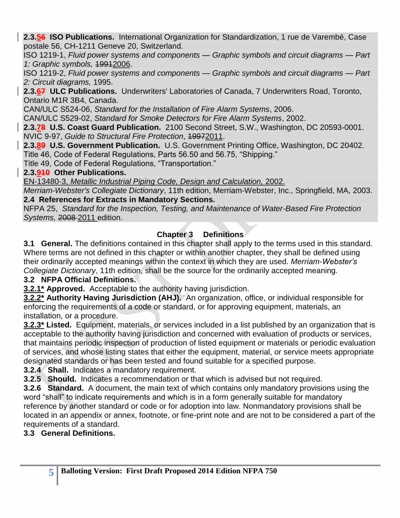
2.3.56 ISO Publications. International Organization for Standardization, 1 rue de Varembé, Case postale 56, CH-1211 Geneve 20, Switzerland. ISO 1219-1, Fluid power systems and components — Graphic symbols and circuit diagrams — Part 1: Graphic symbols, 19912006. ISO 1219-2, Fluid power systems and components — Graphic symbols and circuit diagrams — Part 2: Circuit diagrams, 1995. 2.3.67 ULC Publications. Underwriters' Laboratories of Canada, 7 Underwriters Road, Toronto, Ontario M1R 3B4, Canada. CAN/ULC S524-06, Standard for the Installation of Fire Alarm Systems, 2006. CAN/ULC S529-02, Standard for Smoke Detectors for Fire Alarm Systems, 2002. 2.3.78 U.S. Coast Guard Publication. 2100 Second Street, S.W., Washington, DC 20593-0001. NVIC 9-97, Guide to Structural Fire Protection, 19972011. 2.3.89 U.S. Government Publication. U.S. Government Printing Office, Washington, DC 20402. Title 46, Code of Federal Regulations, Parts 56.50 and 56.75, “Shipping.” Title 49, Code of Federal Regulations, “Transportation.” 2.3.910 Other Publications. EN-13480-3, Metallic Industrial Piping Code, Design and Calculation, 2002. Merriam-Webster's Collegiate Dictionary, 11th edition, Merriam-Webster, Inc., Springfield, MA, 2003. 2.4 References for Extracts in Mandatory Sections. NFPA 25, Standard for the Inspection, Testing, and Maintenance of Water-Based Fire Protection Systems, 2008 2011 edition.
Chapter 3 Definitions 3.1 General. The definitions contained in this chapter shall apply to the terms used in this standard. Where terms are not defined in this chapter or within another chapter, they shall be defined using their ordinarily accepted meanings within the context in which they are used. Merriam-Webster’s Collegiate Dictionary, 11th edition, shall be the source for the ordinarily accepted meaning. 3.2 NFPA Official Definitions. 3.2.1* Approved. Acceptable to the authority having jurisdiction. 3.2.2* Authority Having Jurisdiction (AHJ). An organization, office, or individual responsible for enforcing the requirements of a code or standard, or for approving equipment, materials, an installation, or a procedure. 3.2.3* Listed. Equipment, materials, or services included in a list published by an organization that is acceptable to the authority having jurisdiction and concerned with evaluation of products or services, that maintains periodic inspection of production of listed equipment or materials or periodic evaluation of services, and whose listing states that either the equipment, material, or service meets appropriate designated standards or has been tested and found suitable for a specified purpose. 3.2.4 Shall. Indicates a mandatory requirement. 3.2.5 Should. Indicates a recommendation or that which is advised but not required. 3.2.6 Standard. A document, the main text of which contains only mandatory provisions using the word “shall” to indicate requirements and which is in a form generally suitable for mandatory reference by another standard or code or for adoption into law. Nonmandatory provisions shall be located in an appendix or annex, footnote, or fine-print note and are not to be considered a part of the requirements of a standard. 3.3 General Definitions.

6 Balloting Version: First Draft Proposed 2014 Edition NFPA 750
First Revision No. 96:NFPA 750-2010 [FR 54: FileMaker]
3.3.1 Acceptance Test Plan. A complete step-by-step description of the proposed acceptance test procedure that identifies all devices, controls, and functions to be tested and how the test will be conducted. 3.3.12* Additive. Any chemical or mixture of chemicals intentionally introduced into the system. 3.3.23* Additive Proportioning. Additive proportioning is the method (such as premix, metered, or balanced pressure) used for the introduction of an additive or additive mixture at the recommended percent ratio into the water system.
First Revision No. #:NFPA 750-2010 [FR 119: FileMaker]
3.3.3 Deluge System. A water mist system using open nozzles attached to a piping system that is connected to a water supply through a valve that is opened by means of a detection system installed in the same area as the mist nozzles. When the valve opens, water flows into the piping system and discharges through all nozzles attached to the system. 3.3.4* Dvf. A drop diameter such that the cumulative volume, from zero diameter to this respective
diameter, is the fraction, f, of the corresponding sum of the total distribution. 3.3.5* Enclosure. A confined or partially confined volume. 3.3.6 Escutcheon. A protective or ornamental plate or flange. 3.3.7 Fire Control. Limiting the size of a fire by distribution of water so as to decrease the heat release rate and pre-wet adjacent combustibles, while controlling ceiling gas temperatures to avoid structural damage. 3.3.8 Fire Extinguishment. The complete suppression of a fire until there are no burning combustibles. 3.3.9 Fire Suppression. The sharp reduction of the rate of heat release of a fire and the prevention of regrowth. 3.3.10 High Pressure System. A water mist system where the distribution system piping is exposed to pressures of 34.5 bar (500 psi) or greater. 3.3.11 Intermediate Pressure System. A water mist system where the distribution system piping is exposed to pressures greater than 12.1 bar (175 psi) but less than 34.5 bar (500 psi). 3.3.12 Low Pressure System. A water mist system where the distribution piping is exposed to pressures of 12.1 bar (175 psi) or less.
First Revision No. 12:NFPA 750-2010 [FR 13: FileMaker]
3.3.13 Pressure. 3.3.13.1 Nozzle Operating Pressure. The pressure range at which nozzles are listed to control, suppress, or extinguish a fire. 3.3.13.2 Standby Pressure. The pressure that exists in the distribution system in the static state, prior to nozzle discharge. 3.3.13.3 System Design Pressure. The maximum pressure a system or component is rated to withstand. 3.3.2313.4 Working Pressure. The maximum anticipated static (nonflowing) or pressure applied to the system components exclusive of surge pressures.

7 Balloting Version: First Draft Proposed 2014 Edition NFPA 750
First Revision No. 13:NFPA 750-2010 [FR 67: FileMaker]
3.3.14 Pressure Relief Device. A device designed for the purpose of preventing pressure levels in excess of the design pressure of the system, the system components, or both.
First Revision No. 13:NFPA 750-2010
[FR 4: FileMaker] 3.3.15 Pressure-Regulating Valve. A valve designed for the purpose of reducing, regulating, controlling, or restricting water pressure. 3.3.1316 Propellant. Compressed gas used as a prime mover to push water out of storage vessels, through pipe networks, or through distribution components. 3.3.1417* Shall be Considered. Requires an objective assessment, the results and basis of which are documented, to determine to what extent the specific factor, criterion, guideline, standard, and so forth, is incorporated into or satisfied by the design. 3.3.1518 Single-Fluid System. A water mist system utilizing a single piping system to supply each nozzle. 3.3.1619 Supervision. In water-based fire protection systems, a means of monitoring system status and indicating abnormal conditions. [25, 2008]
First Revision No. #:NFPA 750-2010 [FR 120: FileMaker]
3.3.17 Total Compartment Application System. A system designed to discharge water mist to protect all hazards in an enclosure.
First Revision No. 1:NFPA 750-2010
[FR 7: FileMaker] 3.3.18 3.3.20 Twin–Fluid System. A water mist system in which water and an atomizing media medium are separately supplied to and mixed at the water mist nozzle. the water mist nozzle utilizing a separate piping system for each medium or a single piping system for both.
First Revision No. 9:NFPA 750-2010 [FR 68: FileMaker]
3.3.21 Unloader Valve. A valve that is designed to relieve excess flow below pump capacity at set pump pressure. [20, 2013]
First Revision No. 65:NFPA 750-2010
[FR 90: FileMaker] 3.3.1922* Water Mist. A water spray for which the Dv0.99, for the flow-weighted cumulative volumetric distribution of water droplets, is less than 1000 microns µm at the within the nozzle operating pressure range. minimum design operating pressure of the water mist nozzle. 3.3.2123 Water Mist Nozzle. A special purpose device, containing one or more orifices, designed to produce and deliver a water spray meeting either the definition of water mist or meeting the specific requirements of an approved water mist fire test protocol. (See Annex C.) 3.3.2123.1 Automatic Water Mist Nozzles. Nozzles that operate independently of other nozzles by means of a detection/activation device built into the nozzle.
First Revision No. 2:NFPA 750-2010 [FR 8: FileMaker]
3.3.21.2 3.3.23.2 Hybrid Multi-functional Water Mist Nozzles. Nozzles capable of operation using both automatic and nonautomatic means.
8 Balloting Version: First Draft Proposed 2014 Edition NFPA 750
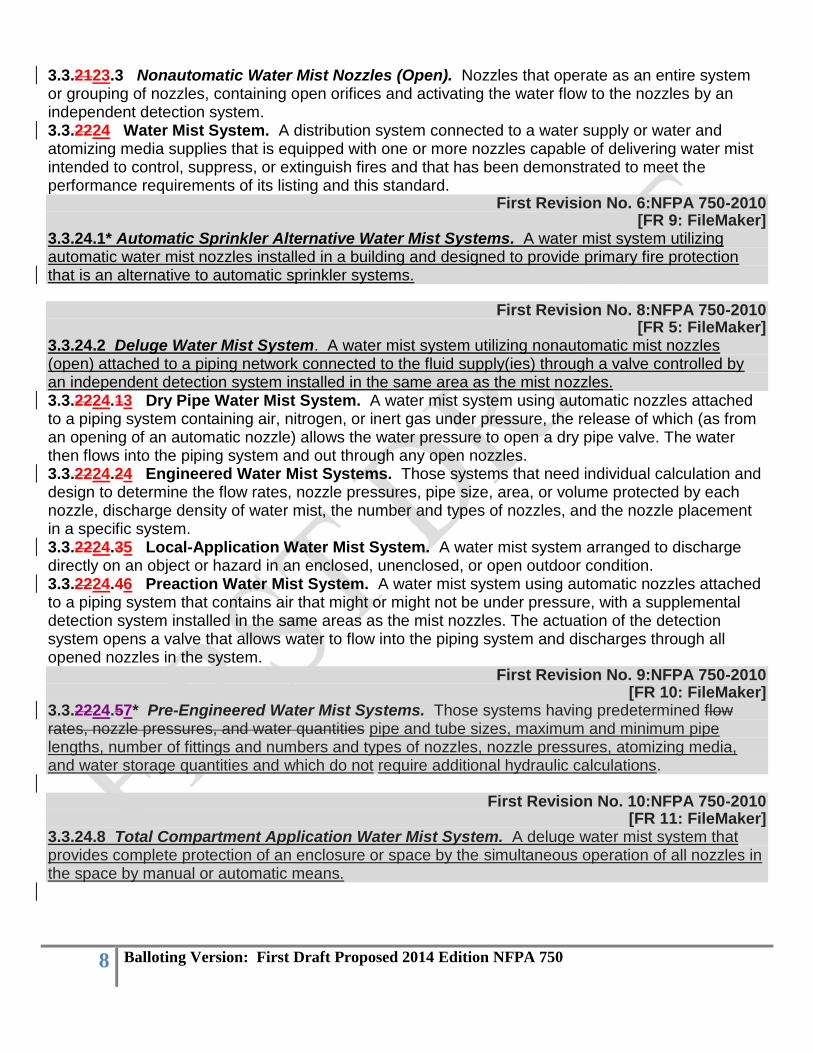
3.3.2123.3 Nonautomatic Water Mist Nozzles (Open). Nozzles that operate as an entire system or grouping of nozzles, containing open orifices and activating the water flow to the nozzles by an independent detection system. 3.3.2224 Water Mist System. A distribution system connected to a water supply or water and atomizing media supplies that is equipped with one or more nozzles capable of delivering water mist intended to control, suppress, or extinguish fires and that has been demonstrated to meet the performance requirements of its listing and this standard.
First Revision No. 6:NFPA 750-2010 [FR 9: FileMaker]
3.3.24.1* Automatic Sprinkler Alternative Water Mist Systems. A water mist system utilizing automatic water mist nozzles installed in a building and designed to provide primary fire protection that is an alternative to automatic sprinkler systems.
First Revision No. 8:NFPA 750-2010
[FR 5: FileMaker] 3.3.24.2 Deluge Water Mist System. A water mist system utilizing nonautomatic mist nozzles (open) attached to a piping network connected to the fluid supply(ies) through a valve controlled by an independent detection system installed in the same area as the mist nozzles. 3.3.2224.13 Dry Pipe Water Mist System. A water mist system using automatic nozzles attached to a piping system containing air, nitrogen, or inert gas under pressure, the release of which (as from an opening of an automatic nozzle) allows the water pressure to open a dry pipe valve. The water then flows into the piping system and out through any open nozzles. 3.3.2224.24 Engineered Water Mist Systems. Those systems that need individual calculation and design to determine the flow rates, nozzle pressures, pipe size, area, or volume protected by each nozzle, discharge density of water mist, the number and types of nozzles, and the nozzle placement in a specific system. 3.3.2224.35 Local-Application Water Mist System. A water mist system arranged to discharge directly on an object or hazard in an enclosed, unenclosed, or open outdoor condition. 3.3.2224.46 Preaction Water Mist System. A water mist system using automatic nozzles attached to a piping system that contains air that might or might not be under pressure, with a supplemental detection system installed in the same areas as the mist nozzles. The actuation of the detection system opens a valve that allows water to flow into the piping system and discharges through all opened nozzles in the system.
First Revision No. 9:NFPA 750-2010 [FR 10: FileMaker]
3.3.2224.57* Pre-Engineered Water Mist Systems. Those systems having predetermined flow rates, nozzle pressures, and water quantities pipe and tube sizes, maximum and minimum pipe lengths, number of fittings and numbers and types of nozzles, nozzle pressures, atomizing media, and water storage quantities and which do not require additional hydraulic calculations.
First Revision No. 10:NFPA 750-2010 [FR 11: FileMaker]
3.3.24.8 Total Compartment Application Water Mist System. A deluge water mist system that provides complete protection of an enclosure or space by the simultaneous operation of all nozzles in the space by manual or automatic means.

9 Balloting Version: First Draft Proposed 2014 Edition NFPA 750
First Revision No. 11:NFPA 750-2010 [FR 12: FileMaker]
3.3.24.9 Zoned Application Water Mist System. A total compartment application water mist system utilizing nonautomatic nozzles, or intermixed nonautomatic and automatic nozzles, in which the piping network is subdivided into predetermined zones controlled by individual control valves, and which protects a predetermined portion of the compartment by the manual or automatic activation of a selected group of nozzles. 3.3.2025 Water Mist, Atomizing Media. Compressed air or other gases that produce water mist by mechanical mixing with water.
First Revision No. #:NFPA 750-2010 [FR 121: FileMaker]
3.3.24 Zoned Application System. A system designed to protect hazards in a predetermined portion of an enclosure.
Chapter 4 General 4.1* General. 4.1.1 Use and Limitations. 4.1.1.1 Water mist systems shall be permitted for use with a wide range of performance objectives, including the following: (1) Fire extinguishment (2) Fire suppression (3) Fire control (4) Temperature control (5) Exposure protection 4.1.1.2* Water mist systems shall not be used for direct application to materials that react with water to produce violent reactions or significant amounts of hazardous products. Such materials include the following: (1) Reactive metals, such as lithium, sodium, potassium, magnesium, titanium, zirconium, uranium,
and plutonium (2) Metal alkoxides, such as sodium methoxide (3) Metal amides, such as sodium amide (4) Carbides, such as calcium carbide (5) Halides, such as benzoyl chloride and aluminum chloride (6) Hydrides, such as lithium aluminum hydride (7) Oxyhalides, such as phosphorus oxybromide (8) Silanes, such as trichloromethylsilane (9) Sulfides, such as phosphorus pentasulfide (10) Cyanates, such as methylisocyanate 4.1.1.3 Water mist systems shall not be used for direct application to liquefied gases at cryogenic temperatures (such as liquefied natural gas), which boil violently when heated by water. 4.2* Safety. 4.2.1* Electrical Clearances. 4.2.1.1* All system components shall be located to maintain minimum clearances from unenclosed and uninsulated energized electrical components in accordance with NFPA 70, National Electrical Code. 4.2.1.2 Where the design basic insulation level (BIL) is not known and where nominal voltage is used for the design criteria, the highest minimum clearance specified for this group shall be used.

10 Balloting Version: First Draft Proposed 2014 Edition NFPA 750
4.2.1.3 The selected clearance to ground shall satisfy the greater of the switching surges or BIL duty, rather than being based on nominal voltage. 4.2.1.4 The clearance between uninsulated energized parts of the electrical system equipment and any portion of the water mist system shall not be less than the minimum clearance provided elsewhere for electrical system insulation on any individual component. 4.2.2 Environmental Factors. 4.2.2.1 When selecting water mist to protect a hazard area, the effects of water runoff on the environment shall be considered.
First Revision No. 117:NFPA 750-2010 [FR 16: FileMaker]
Chapter 5 Classification of Occupancies. 5.1* Classification of Occupancies. 5.1.1 Occupancy classifications for this standard shall relate to water mist system design, installation, and water supply requirements only. 5.1.2 Occupancy classifications shall not be intended to be a general classification of occupancy hazards. 5.2* Light Hazard Occupancies. Light hazard occupancies shall be defined as occupancies or portions of other occupancies where the quantity and/or combustibility of contents is low and fires with relatively low rates of heat release are expected. 5.3* Ordinary Hazard Occupancies. 5.3.1* Ordinary Hazard (Group 1). Ordinary hazard (Group 1) occupancies shall be defined as occupancies or portions of other occupancies where combustibility is low, quantity of combustibles is moderate, stockpiles of combustibles do not exceed 8 ft (2.4 m), and fires with moderate rates of heat release are expected. 5.3.2* Ordinary Hazard (Group 2). Ordinary hazard (Group 2) occupancies shall be defined as occupancies or portions of other occupancies where the quantity and combustibility of contents are moderate to high, where stockpiles of contents with moderate rates of heat release do not exceed 12 ft (3.66 m), and stockpiles of contents with high rates of heat release do not exceed 8 ft (2.4 m). 5.4 Extra Hazard Occupancies. 5.4.1* Extra Hazard (Group 1). Extra hazard (Group 1) occupancies shall be defined as occupancies or portions of other occupancies where the quantity and combustibility of contents are very high and dust, lint, or other materials are present, introducing the probability of rapidly developing fires with high rates of heat release but with little or no combustible or flammable liquids. 5.4.2* Extra Hazard (Group 2). Extra hazard (Group 2) occupancies shall be defined as occupancies or portions of other occupancies with moderate to substantial amounts of flammable or combustible liquids or occupancies where shielding of combustibles is extensive. 5.5* Special Occupancy Requirements. Water mist systems shall be permitted to be used for special occupancies provided that they have been listed for such occupancies. 5.6 Residential Occupancies. 5.6.1 Residential Occupancies up to and Including Four Stories in Height. Residential Occupancies shall include the following, as defined in NFPA 101®, Life Safety Code®: (1) Apartment buildings (2) Lodging and rooming houses (3) Board and care facilities (4) Hotels, motels, and dormitories 5.6.2 One- and Two-Family Dwellings. One- and two-family dwellings shall be defined as any detached building or any part of a townhouse structure that is separated from the remainder of the
11 Balloting Version: First Draft Proposed 2014 Edition NFPA 750
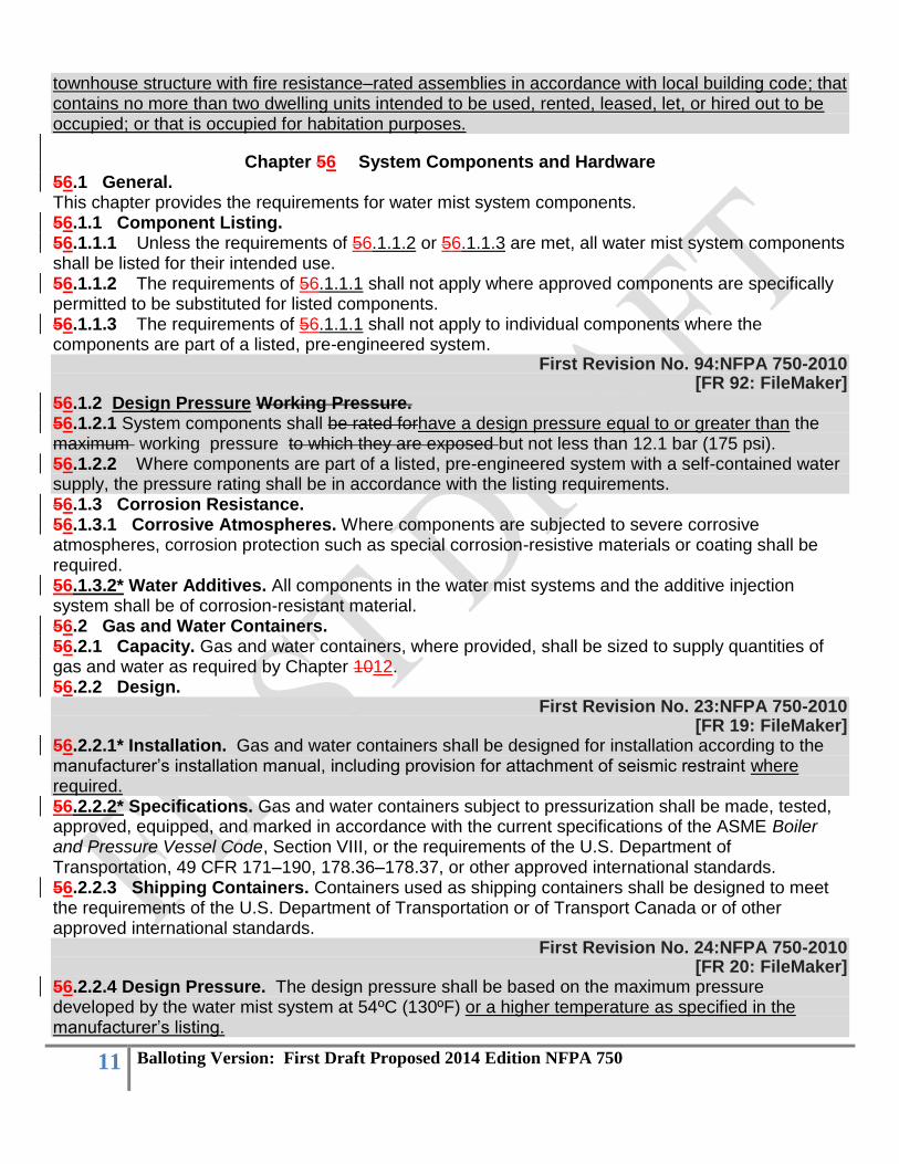
townhouse structure with fire resistance–rated assemblies in accordance with local building code; that contains no more than two dwelling units intended to be used, rented, leased, let, or hired out to be occupied; or that is occupied for habitation purposes.
Chapter 56 System Components and Hardware 56.1 General. This chapter provides the requirements for water mist system components. 56.1.1 Component Listing. 56.1.1.1 Unless the requirements of 56.1.1.2 or 56.1.1.3 are met, all water mist system components shall be listed for their intended use. 56.1.1.2 The requirements of 56.1.1.1 shall not apply where approved components are specifically permitted to be substituted for listed components. 56.1.1.3 The requirements of 56.1.1.1 shall not apply to individual components where the components are part of a listed, pre-engineered system.
First Revision No. 94:NFPA 750-2010 [FR 92: FileMaker]
56.1.2 Design Pressure Working Pressure. 56.1.2.1 System components shall be rated forhave a design pressure equal to or greater than the maximum working pressure to which they are exposed but not less than 12.1 bar (175 psi). 56.1.2.2 Where components are part of a listed, pre-engineered system with a self-contained water supply, the pressure rating shall be in accordance with the listing requirements. 56.1.3 Corrosion Resistance. 56.1.3.1 Corrosive Atmospheres. Where components are subjected to severe corrosive atmospheres, corrosion protection such as special corrosion-resistive materials or coating shall be required. 56.1.3.2* Water Additives. All components in the water mist systems and the additive injection system shall be of corrosion-resistant material. 56.2 Gas and Water Containers. 56.2.1 Capacity. Gas and water containers, where provided, shall be sized to supply quantities of gas and water as required by Chapter 1012. 56.2.2 Design.
First Revision No. 23:NFPA 750-2010 [FR 19: FileMaker]
56.2.2.1* Installation. Gas and water containers shall be designed for installation according to the manufacturer’s installation manual, including provision for attachment of seismic restraint where required. 56.2.2.2* Specifications. Gas and water containers subject to pressurization shall be made, tested, approved, equipped, and marked in accordance with the current specifications of the ASME Boiler and Pressure Vessel Code, Section VIII, or the requirements of the U.S. Department of Transportation, 49 CFR 171–190, 178.36–178.37, or other approved international standards. 56.2.2.3 Shipping Containers. Containers used as shipping containers shall be designed to meet the requirements of the U.S. Department of Transportation or of Transport Canada or of other approved international standards.
First Revision No. 24:NFPA 750-2010 [FR 20: FileMaker]
56.2.2.4 Design Pressure. The design pressure shall be based on the maximum pressure developed by the water mist system at 54ºC (130ºF) or a higher temperature as specified in the manufacturer’s listing.
12 Balloting Version: First Draft Proposed 2014 Edition NFPA 750
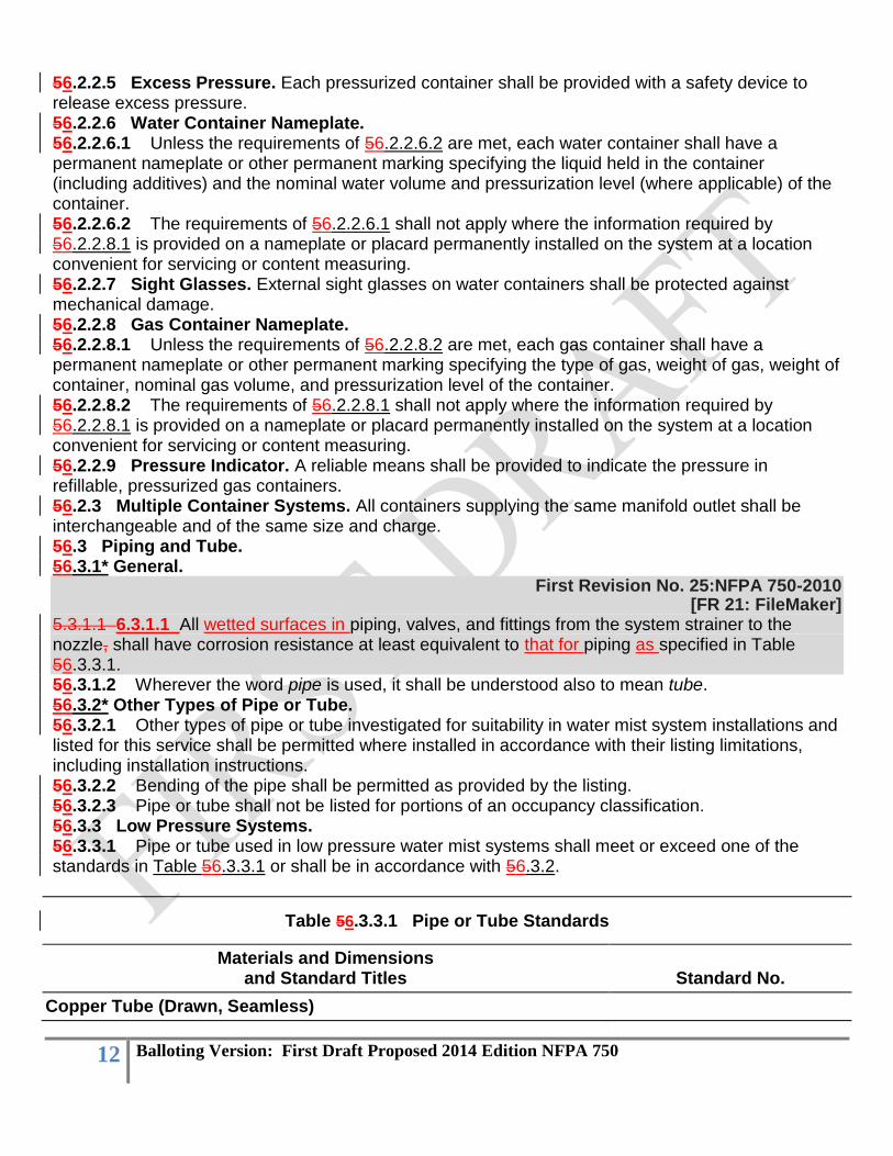
56.2.2.5 Excess Pressure. Each pressurized container shall be provided with a safety device to release excess pressure. 56.2.2.6 Water Container Nameplate. 56.2.2.6.1 Unless the requirements of 56.2.2.6.2 are met, each water container shall have a permanent nameplate or other permanent marking specifying the liquid held in the container (including additives) and the nominal water volume and pressurization level (where applicable) of the container. 56.2.2.6.2 The requirements of 56.2.2.6.1 shall not apply where the information required by 56.2.2.8.1 is provided on a nameplate or placard permanently installed on the system at a location convenient for servicing or content measuring. 56.2.2.7 Sight Glasses. External sight glasses on water containers shall be protected against mechanical damage. 56.2.2.8 Gas Container Nameplate. 56.2.2.8.1 Unless the requirements of 56.2.2.8.2 are met, each gas container shall have a permanent nameplate or other permanent marking specifying the type of gas, weight of gas, weight of container, nominal gas volume, and pressurization level of the container. 56.2.2.8.2 The requirements of 56.2.2.8.1 shall not apply where the information required by 56.2.2.8.1 is provided on a nameplate or placard permanently installed on the system at a location convenient for servicing or content measuring. 56.2.2.9 Pressure Indicator. A reliable means shall be provided to indicate the pressure in refillable, pressurized gas containers. 56.2.3 Multiple Container Systems. All containers supplying the same manifold outlet shall be interchangeable and of the same size and charge. 56.3 Piping and Tube. 56.3.1* General.
First Revision No. 25:NFPA 750-2010 [FR 21: FileMaker]
5.3.1.1 6.3.1.1 All wetted surfaces in piping, valves, and fittings from the system strainer to the nozzle, shall have corrosion resistance at least equivalent to that for piping as specified in Table 56.3.3.1. 56.3.1.2 Wherever the word pipe is used, it shall be understood also to mean tube. 56.3.2* Other Types of Pipe or Tube. 56.3.2.1 Other types of pipe or tube investigated for suitability in water mist system installations and listed for this service shall be permitted where installed in accordance with their listing limitations, including installation instructions. 56.3.2.2 Bending of the pipe shall be permitted as provided by the listing. 56.3.2.3 Pipe or tube shall not be listed for portions of an occupancy classification. 56.3.3 Low Pressure Systems. 56.3.3.1 Pipe or tube used in low pressure water mist systems shall meet or exceed one of the standards in Table 56.3.3.1 or shall be in accordance with 56.3.2.
Table 56.3.3.1 Pipe or Tube Standards
Materials and Dimensions and Standard Titles Standard No.
Copper Tube (Drawn, Seamless)

13 Balloting Version: First Draft Proposed 2014 Edition NFPA 750
Standard Specification for Solder Metal [95-5 (Tin-Antimony-Grade 95TA)]
ASTM B 32
Standard Specification for Seamless Copper Tube* ASTM B 75
Standard Specification for Seamless Copper Water Tube* ASTM B 88
Standard Specification for General Requirements for Wrought Seamless Copper and Copper-Alloy Tube
ASTM B 251
Standard Specification for Liquid and Paste Fluxes for Soldering Applications of Copper and Copper-Alloy Tube
ASTM B 813
Specification for Filler Metals for Brazing and Braze Welding (Classification BCuP-3 or BCuP-4)
AWS A5.8
Stainless Steel
Standard Specification for Seamless and Welded Austenitic Stainless Steel Tubing for General Service
ASTM A 269
Standard Specification for Seamless and Welded Austenitic Stainless Steel Tubing (Small-Diameter) for General Service
ASTM A 632
Standard Specification for Welded, Unannealed Austenitic Stainless Steel Tubular Products
ASTM A 778
Standard Specification for Seamless and Welded Ferritic/Austenitic Stainless Steel Tubing for General Service
ASTM A 789/ A 789M
*Denotes pipe or tube suitable for bending (see 56.3.6) according to ASTM standards. 56.3.3.2 The chemical properties, physical properties, and dimensions of the materials given in Table 56.3.3.1 shall conform at a minimum to the standards cited in the table. 56.3.3.3 Pipe and tube used in low pressure water mist systems shall be designed to withstand a working pressure of not less than 12.1 bar (175 psi). 56.3.3.4 Copper tube as specified in the standards referenced in Table 56.3.3.1 shall have a wall thickness of Type K, L, or M where used in water mist systems. 56.3.4 Intermediate and High Pressure Systems.
First Revision No. 27:NFPA 750-2010 [FR 23: FileMaker]
56.3.4.1* Pipe or tube shall be of noncombustible material having physical and chemical characteristics such that its deterioration under stress can be predicted with reliability. 56.3.4.2* The piping shall be in accordance with ASME B31.1, Power Piping Code, or EN13480-3, Metallic Industrial Piping.
First Revision No. 26:NFPA 750-2010 [FR 24: FileMaker]
56.3.4.3 Where using the equations provided in ASME B31.1, Power Piping Code, or EN13480-3, Metallic Industrial Piping Code, are used to calculate either the maximum working design pressure (Pw) for a specific pipe or tube or the minimum wall thickness (tm) of the pipe or tube for a specific operating working pressure, a steel temperature of 54°C (130°F) or the expected ambient
14 Balloting Version: First Draft Proposed 2014 Edition NFPA 750
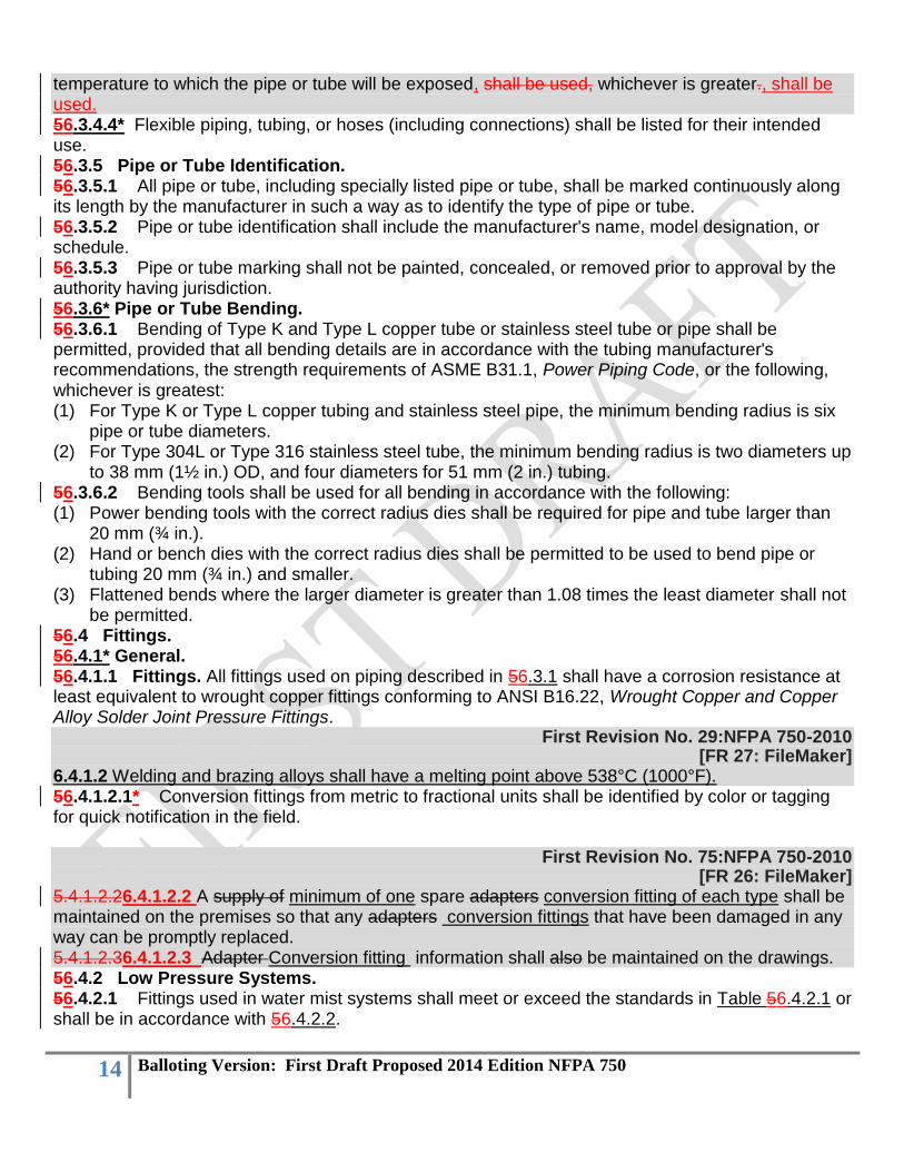
temperature to which the pipe or tube will be exposed, shall be used, whichever is greater., shall be used. 56.3.4.4* Flexible piping, tubing, or hoses (including connections) shall be listed for their intended use. 56.3.5 Pipe or Tube Identification. 56.3.5.1 All pipe or tube, including specially listed pipe or tube, shall be marked continuously along its length by the manufacturer in such a way as to identify the type of pipe or tube. 56.3.5.2 Pipe or tube identification shall include the manufacturer's name, model designation, or schedule. 56.3.5.3 Pipe or tube marking shall not be painted, concealed, or removed prior to approval by the authority having jurisdiction. 56.3.6* Pipe or Tube Bending. 56.3.6.1 Bending of Type K and Type L copper tube or stainless steel tube or pipe shall be permitted, provided that all bending details are in accordance with the tubing manufacturer's recommendations, the strength requirements of ASME B31.1, Power Piping Code, or the following, whichever is greatest: (1) For Type K or Type L copper tubing and stainless steel pipe, the minimum bending radius is six
pipe or tube diameters. (2) For Type 304L or Type 316 stainless steel tube, the minimum bending radius is two diameters up
to 38 mm (1½ in.) OD, and four diameters for 51 mm (2 in.) tubing. 56.3.6.2 Bending tools shall be used for all bending in accordance with the following: (1) Power bending tools with the correct radius dies shall be required for pipe and tube larger than
20 mm (¾ in.). (2) Hand or bench dies with the correct radius dies shall be permitted to be used to bend pipe or
tubing 20 mm (¾ in.) and smaller. (3) Flattened bends where the larger diameter is greater than 1.08 times the least diameter shall not
be permitted. 56.4 Fittings. 56.4.1* General. 56.4.1.1 Fittings. All fittings used on piping described in 56.3.1 shall have a corrosion resistance at least equivalent to wrought copper fittings conforming to ANSI B16.22, Wrought Copper and Copper Alloy Solder Joint Pressure Fittings.
First Revision No. 29:NFPA 750-2010 [FR 27: FileMaker]
6.4.1.2 Welding and brazing alloys shall have a melting point above 538°C (1000°F). 56.4.1.2.1* Conversion fittings from metric to fractional units shall be identified by color or tagging for quick notification in the field.
First Revision No. 75:NFPA 750-2010 [FR 26: FileMaker]
5.4.1.2.26.4.1.2.2 A supply of minimum of one spare adapters conversion fitting of each type shall be maintained on the premises so that any adapters conversion fittings that have been damaged in any way can be promptly replaced. 5.4.1.2.36.4.1.2.3 Adapter Conversion fitting information shall also be maintained on the drawings. 56.4.2 Low Pressure Systems. 56.4.2.1 Fittings used in water mist systems shall meet or exceed the standards in Table 56.4.2.1 or shall be in accordance with 56.4.2.2.
15 Balloting Version: First Draft Proposed 2014 Edition NFPA 750
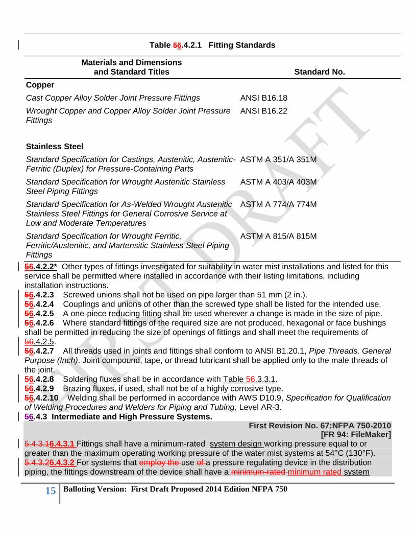
Table 56.4.2.1 Fitting Standards
Materials and Dimensions and Standard Titles Standard No.
Copper
Cast Copper Alloy Solder Joint Pressure Fittings ANSI B16.18
Wrought Copper and Copper Alloy Solder Joint Pressure Fittings
ANSI B16.22
Stainless Steel
Standard Specification for Castings, Austenitic, Austenitic-Ferritic (Duplex) for Pressure-Containing Parts
ASTM A 351/A 351M
Standard Specification for Wrought Austenitic Stainless Steel Piping Fittings
ASTM A 403/A 403M
Standard Specification for As-Welded Wrought Austenitic Stainless Steel Fittings for General Corrosive Service at Low and Moderate Temperatures
ASTM A 774/A 774M
Standard Specification for Wrought Ferritic, Ferritic/Austenitic, and Martensitic Stainless Steel Piping Fittings
ASTM A 815/A 815M
56.4.2.2* Other types of fittings investigated for suitability in water mist installations and listed for this service shall be permitted where installed in accordance with their listing limitations, including installation instructions. 56.4.2.3 Screwed unions shall not be used on pipe larger than 51 mm (2 in.). 56.4.2.4 Couplings and unions of other than the screwed type shall be listed for the intended use. 56.4.2.5 A one-piece reducing fitting shall be used wherever a change is made in the size of pipe. 56.4.2.6 Where standard fittings of the required size are not produced, hexagonal or face bushings shall be permitted in reducing the size of openings of fittings and shall meet the requirements of 56.4.2.5. 56.4.2.7 All threads used in joints and fittings shall conform to ANSI B1.20.1, Pipe Threads, General Purpose (Inch). Joint compound, tape, or thread lubricant shall be applied only to the male threads of the joint. 56.4.2.8 Soldering fluxes shall be in accordance with Table 56.3.3.1. 56.4.2.9 Brazing fluxes, if used, shall not be of a highly corrosive type. 56.4.2.10 Welding shall be performed in accordance with AWS D10.9, Specification for Qualification of Welding Procedures and Welders for Piping and Tubing, Level AR-3. 56.4.3 Intermediate and High Pressure Systems.
First Revision No. 67:NFPA 750-2010 [FR 94: FileMaker]
5.4.3.16.4.3.1 Fittings shall have a minimum-rated system design working pressure equal to or greater than the maximum operating working pressure of the water mist systems at 54°C (130°F). 5.4.3.26.4.3.2 For systems that employ the use of a pressure regulating device in the distribution piping, the fittings downstream of the device shall have a minimum-rated minimum rated system

16 Balloting Version: First Draft Proposed 2014 Edition NFPA 750
design working pressure equal to or greater than the maximum anticipated working pressure in the downstream piping. 56.4.3.3 All threads used in joints and fittings shall conform to ANSI B1.20.1, Pipe Threads, General Purpose (Inch). 56.4.3.4 Joint compound, tape, or thread lubricant shall be applied only to the male threads of the joint.
First Revision No. #:NFPA #-year [FR 122: FileMaker]
5.4.3.5 Welding and brazing alloys shall have a melting point above 538°C (1000°F). 56.4.3.65 Welding and brazing shall be performed in accordance with Section IX of the ASME Boiler and Pressure Vessel Code. 56.4.3.76 Where acceptable tubing is joined with compression-type fittings, the manufacturer's pressure temperature ratings for the fitting shall not be exceeded. 56.5 Hangers/Supports. 56.5.1 Supports. All references to hangers shall include supports.
First Revision No. 35:NFPA 750-2010 [FR 28: FileMaker]
6.5.2 Hangers used on low pressure water mist systems shall be permitted to be designed and installed in accordance with NFPA 13, Standard for the Installation of Sprinkler Systems. 56.5.23 Listing. Unless the requirements of 56.5.3 are met, hangers shall be listed for use with the pipe or tube involved. 56.5.34 Special Designed Hangers. 56.5.34.1 The requirements of 56.5.2 shall not apply to hangers where the following conditions are met: (1) Documentation shall be submitted to show that the hangers and hanging method are recognized
as good industry practice for the piping system. (2) Hangers shall be designed to support five times the weight of the pipe or tube when filled with
gas or water, based on the system's use of the pipe or tube, plus 114 kg (250 lb) at each point of piping support.
(3) The points of support shall be able to support the water mist system. (4) Hanger components shall be metal. (5) Plastic inserts shall be permitted in tube clamps to avoid dissimilar metal reactions or dampen
vibrations. 56.5.34.2 Detailed calculations shall be submitted, where required by the authority having jurisdiction, showing the stresses developed in both the hangers and the piping and the safety factors provided. 56.5.45 Bending. Threaded portions of hangers shall not be bent. 56.5.56 Listed Inserts. The use of listed inserts set in concrete to support hangers shall be permitted. 56.5.67 Powder-Driven Fasteners. 56.5.67.1 Unless the requirements of 56.5.6.2 are met, powder-driven fasteners shall not be used to attach hangers to the building structure where systems are required to be protected against earthquakes. 56.5.67.2 The requirements of 56.5.6.1 shall not apply to powder-driven fasteners that are specifically listed for service in seismic areas. 56.6 Nozzles.
17 Balloting Version: First Draft Proposed 2014 Edition NFPA 750
First Revision No. 68:NFPA 750 -2010 [FR 95: FileMaker]
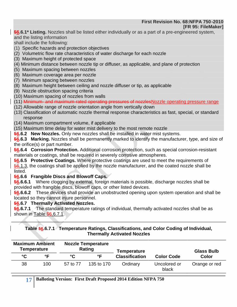
56.6.1* Listing. Nozzles shall be listed either individually or as a part of a pre-engineered system, and the listing information shall include the following: (1) Specific hazards and protection objectives (2) Volumetric flow rate characteristics of water discharge for each nozzle (3) Maximum height of protected space (4) Minimum distance between nozzle tip or diffuser, as applicable, and plane of protection (5) Maximum spacing between nozzles (6) Maximum coverage area per nozzle (7) Minimum spacing between nozzles (8) Maximum height between ceiling and nozzle diffuser or tip, as applicable (9) Nozzle obstruction spacing criteria (10) Maximum spacing of nozzles from walls (11) Minimum- and maximum-rated operating pressures of nozzlesNozzle operating pressure range (12) Allowable range of nozzle orientation angle from vertically down (13) Classification of automatic nozzle thermal response characteristics as fast, special, or standard
response (14) Maximum compartment volume, if applicable (15) Maximum time delay for water mist delivery to the most remote nozzle 56.6.2 New Nozzles. Only new nozzles shall be installed in water mist systems. 56.6.3 Marking. Nozzles shall be permanently marked to identify the manufacturer, type, and size of the orifice(s) or part number. 56.6.4 Corrosion Protection. Additional corrosion protection, such as special corrosion-resistant materials or coatings, shall be required in severely corrosive atmospheres. 56.6.5 Protective Coatings. Where protective coatings are used to meet the requirements of 56.1.3, the coatings shall be applied by the nozzle manufacturer, and the coated nozzle shall be listed. 56.6.6 Frangible Discs and Blowoff Caps. 56.6.6.1 Where clogging by external, foreign materials is possible, discharge nozzles shall be provided with frangible discs, blowoff caps, or other listed devices. 56.6.6.2 These devices shall provide an unobstructed opening upon system operation and shall be located so they cannot injure personnel. 56.6.7 Thermally Activated Nozzles. 56.6.7.1 The standard temperature ratings of individual, thermally activated nozzles shall be as shown in Table 56.6.7.1.
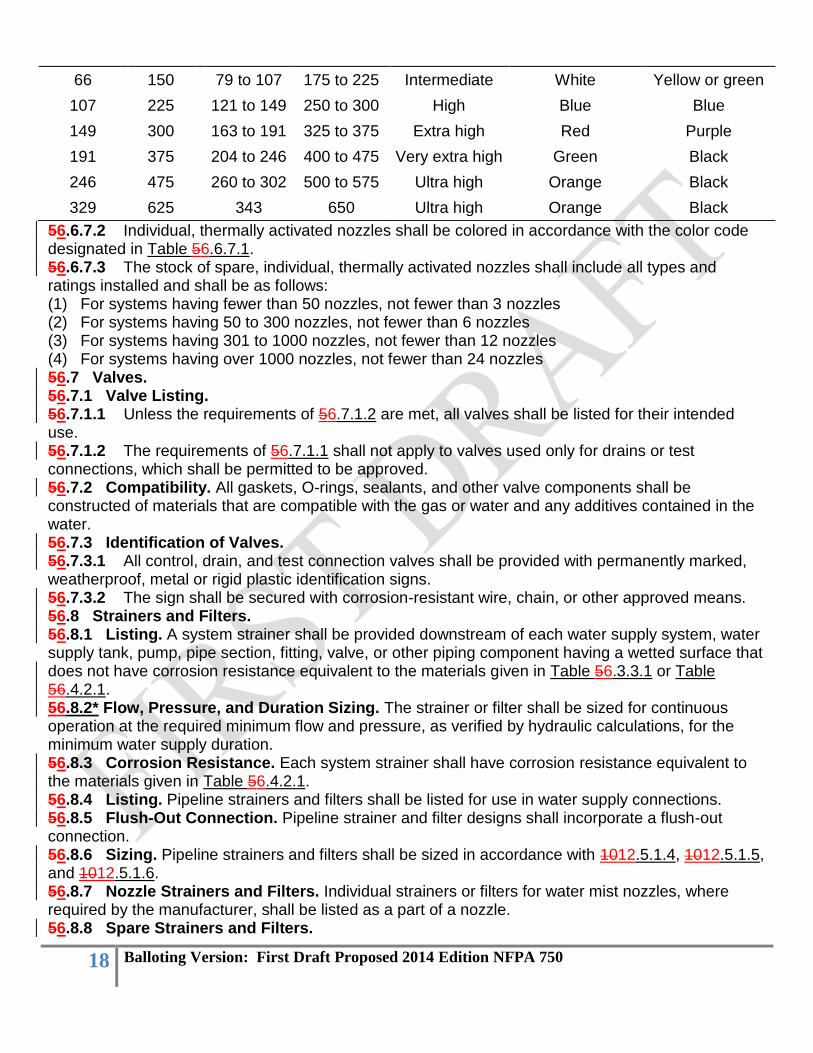
Table 56.6.7.1 Temperature Ratings, Classifications, and Color Coding of Individual, Thermally Activated Nozzles
Maximum Ambient Temperature
Nozzle Temperature Rating Temperature
Classification Color Code Glass Bulb
Color °C °F °C °F
38 100 57 to 77 135 to 170 Ordinary Uncolored or black
Orange or red
18 Balloting Version: First Draft Proposed 2014 Edition NFPA 750
66 150 79 to 107 175 to 225 Intermediate White Yellow or green
107 225 121 to 149 250 to 300 High Blue Blue
149 300 163 to 191 325 to 375 Extra high Red Purple
191 375 204 to 246 400 to 475 Very extra high Green Black
246 475 260 to 302 500 to 575 Ultra high Orange Black
329 625 343 650 Ultra high Orange Black
56.6.7.2 Individual, thermally activated nozzles shall be colored in accordance with the color code designated in Table 56.6.7.1. 56.6.7.3 The stock of spare, individual, thermally activated nozzles shall include all types and ratings installed and shall be as follows: (1) For systems having fewer than 50 nozzles, not fewer than 3 nozzles (2) For systems having 50 to 300 nozzles, not fewer than 6 nozzles (3) For systems having 301 to 1000 nozzles, not fewer than 12 nozzles (4) For systems having over 1000 nozzles, not fewer than 24 nozzles 56.7 Valves. 56.7.1 Valve Listing. 56.7.1.1 Unless the requirements of 56.7.1.2 are met, all valves shall be listed for their intended use. 56.7.1.2 The requirements of 56.7.1.1 shall not apply to valves used only for drains or test connections, which shall be permitted to be approved. 56.7.2 Compatibility. All gaskets, O-rings, sealants, and other valve components shall be constructed of materials that are compatible with the gas or water and any additives contained in the water. 56.7.3 Identification of Valves. 56.7.3.1 All control, drain, and test connection valves shall be provided with permanently marked, weatherproof, metal or rigid plastic identification signs. 56.7.3.2 The sign shall be secured with corrosion-resistant wire, chain, or other approved means. 56.8 Strainers and Filters. 56.8.1 Listing. A system strainer shall be provided downstream of each water supply system, water supply tank, pump, pipe section, fitting, valve, or other piping component having a wetted surface that does not have corrosion resistance equivalent to the materials given in Table 56.3.3.1 or Table 56.4.2.1. 56.8.2* Flow, Pressure, and Duration Sizing. The strainer or filter shall be sized for continuous operation at the required minimum flow and pressure, as verified by hydraulic calculations, for the minimum water supply duration. 56.8.3 Corrosion Resistance. Each system strainer shall have corrosion resistance equivalent to the materials given in Table 56.4.2.1. 56.8.4 Listing. Pipeline strainers and filters shall be listed for use in water supply connections. 56.8.5 Flush-Out Connection. Pipeline strainer and filter designs shall incorporate a flush-out connection. 56.8.6 Sizing. Pipeline strainers and filters shall be sized in accordance with 1012.5.1.4, 1012.5.1.5, and 1012.5.1.6. 56.8.7 Nozzle Strainers and Filters. Individual strainers or filters for water mist nozzles, where required by the manufacturer, shall be listed as a part of a nozzle. 56.8.8 Spare Strainers and Filters.
19 Balloting Version: First Draft Proposed 2014 Edition NFPA 750
56.8.8.1 Spare pipeline and individual nozzle strainers and filters for water mist nozzles, if replaceable, shall be provided and shall include all types and sizes installed. 56.8.8.2 Spare strainers and filters shall be provided to service the nozzles, if replaceable, for the largest single hazard or group of hazards to be protected simultaneously. 56.9 Pump Systems. 56.9.1 Pumps. 56.9.1.1 Installation Standard. Pumps for water mist systems shall be installed in accordance with NFPA 20, Standard for the Installation of Stationary Pumps for Fire Protection. 56.9.1.2 Capacity. Pumps shall be designed with capacities in accordance with 1012.5.2. 56.9.1.3 Overpressure. 56.9.1.3.1 Pumps capable of overpressurizing the system shall be provided with an approved means of pressure relief to prevent an excessive increase in pressure and temperature.
First Revision No. 33:NFPA 750-2010 [FR 96: FileMaker]
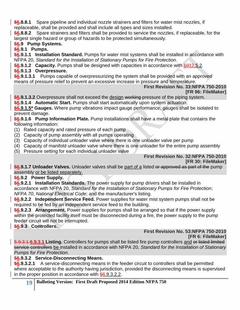
56.9.1.3.2 Overpressure shall not exceed the design working pressure of the piping system. 56.9.1.4 Automatic Start. Pumps shall start automatically upon system actuation. 56.9.1.5* Gauges. Where pump vibrations impact gauge performance, gauges shall be isolated to prevent damage. 56.9.1.6 Pump Information Plate. Pump installations shall have a metal plate that contains the following information: (1) Rated capacity and rated pressure of each pump (2) Capacity of pump assembly with all pumps operating (3) Capacity of individual unloader valve where there is one unloader valve per pump (4) Capacity of manifold unloader valve where there is one unloader for the entire pump assembly (5) Pressure setting for each individual unloader valve
First Revision No. 32:NFPA 750-2010 [FR 30: FileMaker]
56.9.1.7 Unloader Valves. Unloader valves shall be part of a listed or approved as part of the pump assembly or be listed separately. 56.9.2 Power Supply. 56.9.2.1 Installation Standards. The power supply for pump drivers shall be installed in accordance with NFPA 20, Standard for the Installation of Stationary Pumps for Fire Protection; NFPA 70, National Electrical Code; and the manufacturer's listing. 56.9.2.2 Independent Service Feed. Power supplies for water mist system pumps shall not be required to be fed by an independent service feed to the building. 56.9.2.3 Arrangement. Power supplies for pumps shall be arranged so that if the power supply within the protected facility itself must be disconnected during a fire, the power supply to the pump feeder circuit will not be interrupted. 56.9.3 Controllers.
First Revision No. 53:NFPA 750-2010 [FR 6: FileMaker]
5.9.3.1 6.9.3.1 Listing. Controllers for pumps shall be listed fire pump controllers and or listed limited service controllers be installed in accordance with NFPA 20, Standard for the Installation of Stationary Pumps for Fire Protection. 56.9.3.2 Service-Disconnecting Means. 56.9.3.2.1 A service-disconnecting means in the feeder circuit to controllers shall be permitted where acceptable to the authority having jurisdiction, provided the disconnecting means is supervised in the proper position in accordance with 56.9.3.2.2.
20 Balloting Version: First Draft Proposed 2014 Edition NFPA 750
56.9.3.2.2 Supervision for proper position shall be by one of the following methods: (1) Central station, proprietary, or remote station signaling service (2) Local electrical supervision through use of a signaling service that causes a supervisory signal at
a constantly attended location (3) Locking of the disconnecting means in the proper position, with monthly recorded inspections 56.10 Detection, Actuation, Alarm, and Control Systems. 56.10.1 General. 56.10.1.1 Installation, Testing, and Maintenance Standards. Detection, actuation, alarm, and control systems shall be installed, tested, and maintained in accordance with the following protective signaling systems standards as applicable: (1) NFPA 70, National Electrical Code (2) NFPA 72, National Fire Alarm and Signaling Code (3) CAN/ULC S524-06, Standard for the Installation of Fire Alarm Systems (in Canada) (4) CAN/ULC S529-02, Standard for Smoke Detectors for Fire Alarm Systems (in Canada) 56.10.1.2 Automatic Systems. Unless the requirements of 56.10.1.3 are met, where a detection system is used to actuate the water mist system and additive system where used, detection and actuation shall be automatic. 56.10.1.3 Manual Systems. The requirements of 56.10.1.2 shall not apply to manual-only actuation systems where approved by the authority having jurisdiction. 56.10.2 Automatic Detection. 56.10.2.1* Listing. Automatic detection shall be by listed equipment installed in accordance with NFPA 72, National Fire Alarm and Signaling Code. 56.10.2.2 Primary and Standby Power. Adequate and reliable primary and 24-hour minimum standby sources of energy shall be used to provide for operation of the detection, signaling, control, and actuation requirements of the systems. 56.10.2.3 Existing Detection Systems. If an existing detection system is used in a new water mist system, the detection system shall comply with the requirements of this standard. 56.10.3 Operating Devices. 56.10.3.1 Devices. Operating devices shall include water mist releasing devices or valves, discharge controls, and shutdown equipment necessary for successful performance of the system. 56.10.3.2 Operating Methods. Operation shall be by listed mechanical, electrical, or pneumatic equipment. An adequate and reliable source of energy shall be used. 56.10.3.3 Service Conditions. Devices shall be designed for the service they are to encounter and shall not be rendered inoperative or susceptible to accidental operation.
First Revision No. 30:NFPA 750-2010 [FR 32: FileMaker]
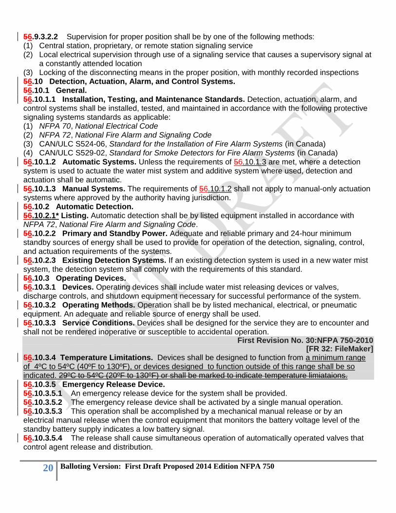
56.10.3.4 Temperature Limitations. Devices shall be designed to function from a minimum range of 4ºC to 54ºC (40ºF to 130ºF), or devices designed to function outside of this range shall be so indicated. 29ºC to 54ºC (20ºF to 130ºF) or shall be marked to indicate temperature limiataions. 56.10.3.5 Emergency Release Device. 56.10.3.5.1 An emergency release device for the system shall be provided. 56.10.3.5.2 The emergency release device shall be activated by a single manual operation. 56.10.3.5.3 This operation shall be accomplished by a mechanical manual release or by an electrical manual release when the control equipment that monitors the battery voltage level of the standby battery supply indicates a low battery signal. 56.10.3.5.4 The release shall cause simultaneous operation of automatically operated valves that control agent release and distribution.

21 Balloting Version: First Draft Proposed 2014 Edition NFPA 750
56.10.3.5.5 Unless the requirements of 56.10.3.5.6 are met, the battery shall be sized to accomplish all functions. 56.10.3.5.6 The requirements of 56.10.3.5 shall not apply to dry and wet pipe systems utilizing individual, thermally activated nozzles. 56.10.3.6 Manual Release Device. 56.10.3.6.1 The manual release device(s) shall be located so as to be accessible at all times. 56.10.3.6.2 The manual release device(s) shall be of distinct appearance and clearly recognizable for the purpose intended. 56.10.3.6.3 Operation of any manual release device shall cause the system to operate in accordance with the design or listing. 56.10.3.6.4 The manual release device(s) shall not require a force of more than 178 N (40 lbf) nor a movement of more than 356 mm (14 in.) to cause activation. 56.10.3.6.5 At least one manual release device for activation shall be located not more than 1.2 m (4 ft) above the floor. 56.10.3.6.6 All devices for shutting down supplementary equipment shall be integral parts of the system and shall function with the system in operation. 56.10.3.6.7 All manual devices shall be identified as to the hazard they protect.
First Revision No. 31:NFPA 750-2010 [FR 33: FileMaker]
6.10.3.6.8 The requirements of 6.10.3.6 shall not apply to dry and wet pipe systems utilizing individual thermally activated nozzles. 56.10.3.7* Supplementary Equipment and Interfaces. All devices for shutting down supplementary equipment or interface with other systems, necessary for effective operation of the water mist system, such as fuel shutoff and ventilation shutoff, shall be considered integral parts of the system and shall function with the system operation unless specifically permitted by the listing. 56.10.4 Control Equipment. 56.10.4.1 Electrical Control Equipment. Automatic control equipment shall be listed and installed in accordance with NFPA 72, National Fire Alarm and Signaling Code. 56.10.4.2 Listing. The control unit shall be listed for release device service. 56.10.4.3 Pneumatic Control Equipment. 56.10.4.3.1* Pneumatic control lines shall be protected against crimping and mechanical damage. 56.10.4.3.2 Unless the requirements of 56.10.4.3.3 or 56.10.4.3.4 are met, pneumatic control lines used to activate the system shall be supervised. 56.10.4.3.3 The requirements of 56.10.4.3.2 shall not apply to pneumatically operated control lines immediately adjacent to the pressurizing source. 56.10.4.3.4 The requirements of 56.10.4.3.2 shall not apply to pneumatic control lines from master to slave cylinders that are located in close proximity to one another. 56.10.4.3.5 The control equipment shall be specifically listed for the number and type of actuating devices utilized, and their compatibility shall have been listed. 56.11 Compatibility. All components of pneumatic, hydraulic, or electrical systems shall be compatible.
Chapter 67 System Requirements First Revision No. 16:NFPA 750-2010
[FR 34: FileMaker] 6.1 7.1 General. Water mist systems shall be described by the following four five parameters as appropriate: (1) System application
22 Balloting Version: First Draft Proposed 2014 Edition NFPA 750
(2) Nozzle type (3) System operation method (4) System media type (5) Classification of occupancy
First Revision No. 36:NFPA 750-2010 [FR 35: FileMaker]
6.2 7.2 System Applications. System applications shall consist of one of the following three four categories: (1) Local-application systems (2) Total compartment application systems (3) Zoned application systems (4) Automatic sprinkler alternative water mist application systems 6.2.1 7.2.1 Local-Application Systems. 7.2.1.1 Local-application systems shall be designed and installed to provide complete distribution of mist on or around the hazard or object to be protected. 6.2.1.1 7.2.1.2 Local-application systems shall be designed to protect an object or a hazard in an enclosed, unenclosed, or open outdoor condition. 6.2.1.2 7.2.1.3 Local-application systems shall be actuated by automatic nozzles or by an independent detection system. 6.2.2 7.2.2 Total Compartment Application Systems. 6.2.2.1 7.2.2.1 Total compartment application systems are shall be designed and installed to provide complete protection of an enclosure or space. 6.2.2.2 7.2.2.2* The complete protection of an enclosure or space shall be achieved by the simultaneous operation of all nozzles in the space by manual or automatic means. 6.2.3* 7.2.3* Zoned Application Systems. 7.2.3.1 Zoned application systems are a subset of the compartment system and are shall be designed to protect a predetermined portion of the compartment by the activation of a selected group of nozzles. 6.2.3.17.2.3.2 Zoned application systems shall be designed and installed to provide complete mist distribution throughout a predetermined portion of an enclosure or space. This shall be achieved by simultaneous operation of a selected group of nozzles in a predetermined portion of the space by manual or automatic means. 6.2.3.2 7.2.3.3 Zoned application systems shall be actuated by automatic nozzles or by an independent detection system. 7.2.4 Automatic Sprinkler Alternative Water Mist Systems. 7.2.4.1 Automatic sprinkler alternative water mist systems shall be designed and installed to provide automatic fire protection throughout a building or area. 7.2.4.2 Automatic sprinkler alternative water mist system devices shall be listed for the intended occupancy classification as described in Chapter 5 unless otherwise permitted in this standard. 7.2.4.3 Automatic sprinkler alternative water mist systems shall be of the wet pipe or dry pipe type. 7.2.4.4 The requirements of 7.2.4.3. shall not apply where environmental or operational conditions dictate whether there is a wet or dry system.
First Revision No. 18:NFPA 750-2010 [FR 18: FileMaker]
67.3 Nozzle Types. Water mist nozzles shall be classified as one of the following three types:
23 Balloting Version: First Draft Proposed 2014 Edition NFPA 750
(1) Automatic (2) Nonautomatic (3) HybridMulti-functional 67.4 System Requirements. 67.4.1 Deluge Systems. 67.4.1.1 Deluge systems shall employ nonautomatic nozzles (open) attached to a piping network connected to the fluid supply(ies) through a valve controlled by an independent detection system installed in the same area as the mist nozzles. 67.4.1.2 When the valve(s) is activated, the fluid shall flow into the piping network and discharge from all nozzles attached thereto. 67.4.2 Wet Pipe Systems. Wet pipe systems shall employ automatic nozzles attached to a piping network pressurized with water up to the nozzles. 67.4.3 Preaction Systems. 67.4.3.1 Preaction systems shall employ automatic nozzles attached to a piping network containing a pressurized gas with a supplemental, independent detection system installed in the same area as the nozzles. 67.4.3.2 Operation of the detection system shall actuate a tripping device that opens the valve, pressurizing the pipe network with water to the nozzles.
First Revision No. 76:NFPA 750-2010 [FR 37: FileMaker]
6.4.3.37.4.3.3 The pressurized piping in all preaction systems shall be supervised to ensure system piping integrity. 67.4.4 Dry Pipe Systems. 67.4.4.1 Dry pipe systems shall employ automatic nozzles attached to a piping network containing a pressurized gas. 67.4.4.2 The loss of pressure in the piping network shall activate a control valve, which causes water to flow into the piping network and out through the activated nozzles.
First Revision No. 19:NFPA 750-2010 [FR 36: FileMaker]
7.4.4.3 The pressurized piping in all dry pipe systems shall be supervised to ensure system integrity. 67.5* Media System Types. Water mist systems shall be classified by two media system types: (1) Single fluid (2) Twin fluid 67.6 Additive Systems. The additive manufacturer or system provider shall be consulted and performance specifications shall be provided to ensure proper operation and reliability. Where additives are used to enhance fire performance, system proportioning accuracy shall comply with the appropriate standards.
Chapter 78 Installation Requirements 78.1 General. This chapter provides requirements for the installation of water mist system components. 78.1.1 Listing. Listed materials and devices shall be installed in accordance with their listing.
First Revision No. 20:NFPA 750-2010 [FR 74: FileMaker]
78.1.2 System Design and Installation Manual. Materials and devices shall be installed in accordance with the manufacturer’s system design and installation manual.

24 Balloting Version: First Draft Proposed 2014 Edition NFPA 750
78.1.3 Corrosive Environments. Systems installed in corrosive environments shall comply with 56.1.3. 78.1.4 Mechanical and Chemical Damage. System components shall be located, installed, or suitably protected so they are not subject to mechanical, chemical, or other damage that could render them inoperative. 78.1.5 Installation and Testing Procedures. Manufacturers shall provide installation and testing procedures to ensure that the system is installed and will operate as intended.
First Revision No. 54:NFPA 750-2010 [FR 38: FileMaker]
8.1.6 Automatic Sprinkler Alternative Water Mist Systems. 8.1.6.1 Spacing and Location of Nozzles. The requirements for spacing, location, and position of water mist nozzles shall be based on the following principles: (1) Nozzles shall be installed throughout the premises unless the nozzles are specifically tested, and the test results demonstrate that omission of water mist nozzles from certain limited areas is permissible. (2) Nozzles shall be located so as not to exceed the spacing criteria specified by the manufacturer in the system design and installation manual. (3) Nozzles shall be positioned and located so as to provide satisfactory performance with respect to activation time and distribution pattern. (4) When nozzles are specifically tested and the test results demonstrate that deviations from clearance requirements to obstructions do not impair the ability of the system to control or suppress a fire, their positioning and locating in accordance with the test results shall be permitted. (5) Clearance between nozzles and ceilings exceeding the maximums specified in the standard or in the manufacturer’s system design and installation manual shall be permitted, provided that tests or calculations demonstrate performance of the automatic water mist nozzles comparable to those installed in conformance with this standard. (6) Furniture, portable wardrobe units, cabinets, trophy cases, and similar objects or features not intended for occupancy, whether freestanding or attached to the finished structure, do not require nozzles to be installed in them. 8.1.6.2 System Protection Area Limitations. The maximum area on any one floor to be protected by water mist supplied by any one water mist system riser or combined system riser shall be as follows: (1) Light hazard: 4831 m2 (52,000 ft2) (2) Ordinary hazard: 4831 m2 (52,000 ft2) (3) Extra hazard: 3716 m2 (40,000 ft2) 8.1.6.3 Mezzanines. The floor area occupied by mezzanines shall not be included in the area limits of 8.1.6.2. 8.1.6.4 Multiple Occupancies Within a Building. Where single automatic sprinkler alternative water mist systems protect extra hazard areas covered by other NFPA standards, in addition to ordinary or light hazard areas, the extra hazard coverage shall not exceed the floor area specified for that hazard and the total area coverage shall not exceed 4831 m2 (52,000 ft2). 8.1.6.5 Multiple Buildings. Multiple buildings attached by canopies, covered breezeways, common roofs, or a common wall(s) shall be permitted to be supplied by a single system riser provided that the maximum system size complies with 8.1.6.2. 78.2 Nozzles. 78.2.1 General. Nozzles shall be installed in accordance with the manufacturer's listing.
25 Balloting Version: First Draft Proposed 2014 Edition NFPA 750
78.2.2 Nozzle Height Limitations. The minimum and maximum heights shall be in accordance with the manufacturer's listing. 78.2.3 Nozzle Spacing Limitations. The minimum and maximum distances between nozzles shall be in accordance with the manufacturer's listing. 78.2.4 Distance from Walls. The minimum and maximum distance from nozzles to walls or partitions shall be in accordance with the manufacturer's listing. 78.2.5* Obstructions to Nozzle Discharge. The location of nozzles with respect to continuous or discontinuous obstructions shall be in accordance with the manufacturer's listing. 78.2.6 Distance Below Ceilings. The distance between the nozzle and the ceiling shall be in accordance with the range (minimum and maximum) identified in the manufacturer's listing. 78.2.7 Spacing Under Pitched or Curved Surfaces. The distance between nozzles in or under a pitched or curved surface shall be in accordance with the manufacturer's listing. 78.2.8 Nozzle Protection. 78.2.8.1 Nozzles subject to mechanical damage shall be protected with listed guards. 78.2.8.2 Guards shall not significantly reduce the effectiveness of the nozzle. 78.2.9 Escutcheons and Cover Plates. 78.2.9.1 Escutcheons used in a recessed or flush-type nozzle installation shall be a part of a listed nozzle assembly. 78.2.9.2 Nonmetallic escutcheons shall be listed. 78.2.9.3 Cover plates used with concealed nozzles shall be part of the listed assembly. 78.2.10 Thermally Activated Nozzle Temperature Ratings. 78.2.10.1 Temperature ratings shall be selected as follows: (1) Where the maximum ceiling temperature does not exceed 38°C (100°F), ordinary temperature
nozzles shall be permitted to be used throughout. (2) Where maximum ceiling temperatures exceed 38°C (100°F), nozzles with temperature ratings in
accordance with the maximum ambient temperatures of Table 56.6.7.1 shall be used. (3) High temperature nozzles shall be permitted to be used throughout. (4) Where high temperature nozzles are not utilized throughout, nozzles of intermediate and high
temperature classifications shall be installed in specific locations as required by 78.2.10.2. 78.2.10.2 The following practices shall be observed to provide nozzles of other than ordinary temperature classification unless other temperatures are determined or unless high temperature nozzles are used throughout. [See Figure 78.2.10.2, Table 78.2.10.2(a), and Table 78.2.10.2(b).] (1) Nozzles in the high temperature zone shall be of the high temperature classification, and nozzles
in the intermediate temperature zone of the intermediate temperature classification. (2) Nozzles located within 305 mm (12 in.) to one side or 762 mm (30 in.) above an uncovered
steam main, heating coil, or radiator shall be of the intermediate temperature classification. (3) Nozzles within 2.1 m (7 ft) of a low pressure blowoff valve that discharges free in a large room
shall be of the high temperature classification. (4) Nozzles under glass or plastic skylights exposed to the direct rays of the sun shall be of the
intermediate temperature classification. (5) Nozzles in an unventilated, concealed space, under an uninsulated roof, or in an unventilated
attic shall be of the intermediate temperature classification. (6) Nozzles in unventilated show windows having high-powered electric lights near the ceiling shall
be of the intermediate temperature classification. (7) Nozzles protecting commercial-type cooking equipment and ventilation systems shall be of the
high or extra high temperature classification as determined by use of a temperature measuring device.

26 Balloting Version: First Draft Proposed 2014 Edition NFPA 750
FIGURE 78.2.10.2 High Temperature and Intermediate Temperature Zones at Unit Heaters.
Table 78.2.10.2(a) Temperature Ratings of Nozzles Based on Distance from Heat Sources
Type of Heat
Condition Ordinary Degree
Rating Intermediate Degree
Rating High Degree Rating
1. Heating ducts
(a) Above More than 775 mm (2 ft 6 in.)
775 mm (2 ft 6 in.) or less
(b) Side and below More than 310 mm (1 ft 0 in.)
310 mm (1 ft 0 in.) or less
(c) Diffuser Any distance except as shown in Intermediate Degree Rating column
Downward discharge: Cylinder with 310 mm (1 ft 0 in.) radius from edge, extending 310 mm (1 ft 0 in.) below and 775 mm (2 ft 6 in.) above
Horizontal discharge: Semi-cylinder with 775 mm (2 ft 6 in.) radius in

27 Balloting Version: First Draft Proposed 2014 Edition NFPA 750
direction of flow, extending 310 mm (1 ft 0 in.) below and 775 mm (2 ft 6 in.) above
2. Unit heater
(a) Horizontal discharge
Discharge side: 2.2 m to 6.2 m (7 ft 0 in. to 20 ft 0 in.) radius pie-shaped cylinder (see Figure 78.2.10.2) extending 2.2 m (7 ft 0 in.) above and 620 mm (2 ft 0 in.) below heater; also 2.2 m (7 ft 0 in.) radius cylinder more than 2.2 m (7 ft 0 in.) above unit heater
2.2 m (7 ft 0 in.) radius cylinder extending 2.2 m (7 ft 0 in.) above and 620 mm (2 ft 0 in.) below unit heater
(b) Vertical downward discharge
2.2 m (7 ft 0 in.) radius cylinder extending upward from an elevation 2.2 m (7 ft 0 in.) above unit heater
2.2 m (7 ft 0 in.) radius cylinder extending from the top of the unit heater to an elevation 2.2 m (7 ft 0 in.) above unit heater
3. Steam mains (uncovered)
(a) Above More than 775 mm (2 ft 6 in.)
775 mm (2 ft 6 in.) or less
(b) Side and below More than 310 mm (1 ft 0 in.)
310 mm (1 ft 0 in.) or less
(c) Blowoff valve More than 2.2 m (7 ft 0 in.)
2.2 m (7 ft 0 in.) or less
Table 78.2.10.2(b) Ratings of Nozzles in Specified Locations
Location Ordinary Degree
Rating Intermediate Degree
Rating High Degree Rating
Skylights Glass or plastic
Attics Ventilated Unventilated
Peaked roof: Metal or thin boards, concealed or not concealed, insulated or uninsulated
Ventilated Unventilated
Flat roof: Metal, Ventilated or Note: For uninsulated

28 Balloting Version: First Draft Proposed 2014 Edition NFPA 750
concealed, insulated or uninsulated
unventilated roof, climate and occupancy could necessitate intermediate nozzles. Check on job.
Flat roof: Metal, concealed, insulated or uninsulated
Ventilated Unventilated
Show windows Ventilated Unventilated
78.2.10.3 In case of occupancy change involving temperature change, the nozzles shall be changed accordingly. 78.3 Pipe and Tubing. 78.3.1 Installation Manual. Piping and tubing for water mist systems shall be installed in accordance with the manufacturer's installation manual.
First Revision No. 21:NFPA 750-2010 [FR 40: FileMaker]
78.3.2 Installation Standards. All water and atomizing media piping and tubing for water mist systems shall be installed in accordance with one of the following: (1) ASME B31.1, Power Piping Code (2) EN13480-3, Metallic Industrial Piping (23) Water piping only, in low pressure systems installed in accordance with NFPA 13, Standard for the Installation of Sprinkler Systems, only for water piping in low-pressure systems. (34) Piping installed in accordance with its a water mist system listing where the listing provides installation criteria are different from ASTM B31.1, Power Piping Code, or EN13480-3, Metallic Industrial Piping
First Revision No. 69:NFPA 750-2010 [FR 97: FileMaker]
78.3.3 Pressure Rating. All system piping, tubing, and hose shall be rated for the maximum working pressure to which they are exposed. 78.3.43 Listing. Any flexible piping, tubing, hose, or combination thereof shall be constructed and installed in accordance with the manufacturer's listing. 78.3.54 Piping Support. 78.3.54.1 The system piping shall be supported by structural elements that are independent of the ceiling sheathing to prevent lateral and horizontal movement upon system actuation. 78.3.54.2 Tube hangers shall be spaced in accordance with Table 78.3.54.2.
Table 7.3.54.2 Tube Hanger Maximum Spacing
Tube O.D. Maximum Distance Between Hangers
mm in. m ft
6–14 ¼, 3⁄8, ½ 1.21 4.0
15–22 ¾–7⁄8 1.52 5.0

29 Balloting Version: First Draft Proposed 2014 Edition NFPA 750
23–28 1 1.82 6.0
30–38 1¼–1½ 2.12 7.0
40–49 2.42 8.0
50–59 3.00 10.0
60–70 3.33 11.0
71–89 3.64 12.0
90–108 3.94 13.0
78.3.65 System Drainage. All system piping and fittings shall be installed so that the entire system can be drained. 78.3.76 Location of Hangers and Supports. 78.3.76.1 Hangers and supports shall be located in accordance with the requirements contained within the system's design manual. 78.3.76.2 For low pressure and intermediate systems, steel pipe and copper tubing shall be supported in accordance with NFPA 13, Standard for the Installation of Sprinkler Systems. 78.3.76.3 The length of an unsupported arm over to a nozzle shall not exceed 0.6 m (2 ft) for steel pipe or 0.3 m (1 ft) for steel tubing. 78.3.87* Protection of System Components Against Damage Where Subject to Earthquakes. Where subject to earthquakes, water mist systems shall be protected to prevent pipe breakage in accordance with the seismic requirements of NFPA 13, Standard for the Installation of Sprinkler Systems. 78.4 Fittings. 78.4.1 Listing. All system fittings shall be installed in accordance with the manufacturer's listing. 78.4.2 Low Pressure Systems. In addition to the requirements of 78.4.1, all fittings installed in low pressure water mist systems shall conform to NFPA 13, Standard for the Installation of Sprinkler Systems.
First Revision No. 70:NFPA 750-2010 [FR 98: FileMaker]
7.4.3 Pressure Rating. All fittings shall be rated for the maximum working pressure to which they are exposed. 78.5 Gas and Water Storage Containers. 78.5.1 Listing. Storage containers shall be installed, mounted, and braced in accordance with the manufacturer's listing. 78.5.2 Accessibility. Storage containers and accessories shall be installed so that inspection, testing, recharging, and other maintenance are facilitated and interruption to protection is held to a minimum. 78.5.3* Location. Storage containers shall be located as close as possible to the hazard or within the hazards they protect and shall not be exposed to fire or mechanical damage in a manner that affects performance. 78.5.4 Damage. Storage containers shall be protected from severe weather conditions and from mechanical, chemical, or other damage. 78.5.5 High Pressure Storage Containers. 78.5.5.1 Standards. High pressure containers or cylinders shall be constructed, tested, and marked in accordance with recognized international standards, such as the U.S. Department of Transportation, 49 CFR, 171-190, 178.36-178.37, specifications (in effect upon date of manufacture and test) for DOT-3A, 3AA-1800, or higher seamless steel cylinders.
30 Balloting Version: First Draft Proposed 2014 Edition NFPA 750
78.5.5.2 Preshipping Testing. Charged cylinders shall be tested for tightness before shipment in accordance with an approved procedure. 78.5.5.3 Manifolded Cylinders. 78.5.5.3.1 Where manifolded, cylinders shall be mounted and supported in a rack provided for this purpose, including facilities for convenient, individual servicing or weighing of contents. 78.5.5.3.2 When any cylinder is removed for maintenance, automatic means shall be provided to prevent leakage from the manifold if the system is operated. 78.5.5.4 Storage Temperatures. 78.5.5.4.1 Storage temperatures shall be maintained within the range specified in the manufacturer's listing. 78.5.5.4.2 External heating or cooling shall be an approved method to keep the temperature of the storage container within desired ranges. 78.5.5.5 Container Securement. Containers shall be secured with manufacturer-listed supports to prevent container movement and possible physical damage. 78.5.6 Intermediate and Low Pressure Storage Cylinders. 78.5.6.1 Unless the requirements of 78.5.6.3 are met, the pressure container shall be made, tested, approved, equipped, and marked in accordance with the current specifications of the ASME Boiler and Pressure Vessel Code, Section VIII, or the requirements of U.S. Department of Transportation, 49 CFR, 171-190, 178.36-178.37, or other approved international standards.
First Revision No. 71:NFPA 750-2010 [FR 99: FileMaker]
7.5.6.28.5.6.2 The system design working pressure shall be in accordance with the manufacturer’s listing. 78.5.6.3 The requirements of 78.5.6.1 shall not apply to pressure containers for heated water mist systems, which shall be in accordance with the manufacturer's listing. 78.5.6.4 Each pressure container shall be equipped with a liquid level gauge, a pressure gauge, and a high/low pressure supervisory alarm set at the values identified in the manufacturer's listing. 78.5.6.5 Media storage containers that become pressurized only during system activation shall not require high/low pressure supervisory alarms. 78.5.6.6 Storage Temperature. 78.5.6.6.1 Storage temperatures shall be maintained within the range specified in the manufacturer's listing. 78.5.6.6.2 External heating or cooling shall be an approved method to keep the temperature of the storage container within desired ranges. 78.5.6.7 Securement. Containers shall be secured with manufacturer-listed supports to prevent container movement and possible physical damage. 78.6 Pumps and Pump Controllers. 78.6.1* Sizing. Pumps shall be sized to meet the required system water flow rate, at the minimum system pressure, as determined by hydraulic calculations. 78.6.2 Automatic Start. Pumps shall start automatically and shall supply water to the water mist system until manually shut off or automatically shut off in accordance with the manufacturer's listing. 78.6.3 Supervisory Service. Unless the requirements of 78.6.4 are met, pumps shall be provided with supervisory service from a listed central station, proprietary, or remote station system or equivalent. 78.6.4 Single Family Dwellings. The requirements of 78.6.3 shall not apply to pumps for single-family dwellings.

31 Balloting Version: First Draft Proposed 2014 Edition NFPA 750
78.6.5 Test Fittings or Hose Outlets. Pumps shall be equipped with a test fitting or hose outlet on the discharge side of the pump to facilitate the annual full-flow pump test required in Table A.1315.2.2. 78.7 Strainers and Filters. 78.7.1 Location. Strainers and filters shall be provided at all water supply connections in accordance with Chapter 10. 78.7.2 Installation. Filters and strainers shall be installed to minimize potential head loss due to accumulation of particulates. 78.8 Valves and Pressure Gauges. 78.8.1 General. 78.8.1.1 All valves shall be installed in accordance with the manufacturer's listing. 78.8.1.2 Valves having components that extend beyond the valve body shall be installed in a manner that does not interfere with the operation of any system components. 78.8.1.3 All valves shall be listed for their particular application and installation. 78.8.1.4 Valves forming part of a listed system shall not be required to be individually listed. 78.8.1.5 Valve Identification. 78.8.1.5.1 All control, drain, and test connection valves shall be provided with permanently marked, weatherproof, metal or rigid plastic identification signs. 78.8.1.5.2 The sign shall be secured by corrosion-resistant wire or chain or by other approved means. 78.8.1.6 Valve Accessibility. System valves and gauges shall be installed such that they are accessible for operation, inspection, and maintenance. 78.8.1.7 Indicating Valves. 78.8.1.7.1 Unless the requirements of 78.8.1.7.2 are met, at least one listed indicating valve shall be installed in each source of water supply. 78.8.1.7.2 The requirements of 78.8.1.7 shall not apply to systems with a single water supply source comprised of a self-contained system (cylinders, containers). 78.8.1.8 Valve Supervision. 78.8.1.8.1 Valves on connections to water supplies, sectional control and isolation valves, and other valves in supply pipes to nozzles and other fixed water-based fire suppression systems shall be supervised by one of the following methods: (1) Central station, proprietary, or remote station signaling service (2) Local signaling service that will cause the sounding of an audible signal at a constantly attended
point (3) Valves locked in the correct position (4) Valves located within fenced enclosures under the control of the owner, sealed in the open
position, and inspected weekly as part of an approved procedure 78.8.1.8.2 Valves controlling manual system activation shall not be locked and shall be supervised in accordance with 78.8.1.8.1(1), 78.8.1.8.1(2), or 78.8.1.8.1(3). 78.8.2 Control and Activation Valves. 78.8.2.1 Control and activation valves shall include any device or valve that automatically opens to supply water to the nozzles after the detection of a fire. 78.8.2.2 Control and activation valves shall operate by an approved mechanical, electrical, or pneumatic means. 78.8.2.3 Control and activation valves shall be installed such that they are not subject to mechanical, chemical, or other damage that would render them inoperative.

32 Balloting Version: First Draft Proposed 2014 Edition NFPA 750
First Revision No. 55:NFPA 750-2010 [FR 42 FileMaker]
78.8.3 Pressure Regulation, and Pressure Relief Valves, and Unloader Valves. 78.8.3.1 Water Pressure Regulating Valves. Valves for Use with Water. 78.8.3.1.1 Pressure regulating valves shall be installed in any portion of the system where the potential exists for the workingsystem pressure to exceed the system designmaximum-rated working pressure of the system, or the system components, or both.
First Revision No. 55:NFPA 750-2010
[FR 73: FileMaker] 7.8.3.1.28.8.3.1.2 These valves shall open when the system at a pressure reaches 95 percent of the greater than the working pressure and less than the system rated design pressure.
First Revision No. 73:NFPA 750-2010 [FR 101: FileMaker]
7.8.3.1.3 8.8.3.1.3 A relief valve of not less than 13 mm (1⁄2 in.) shall be provided on the discharge side of the pressure regulating valve that is set to operate at a pressure not exceeding the system-rated design pressure. 78.8.3.1.4 Unless the requirements of 78.8.3.1.5 are met, a listed indicating valve shall be provided on the inlet side of each pressure reducing valve. 78.8.3.1.5 The requirements of 78.8.3.1.4 shall not apply where the pressure regulating valve meets the listing requirements for use as an indicating valve. 78.8.3.1.6 A waterflow test valve that is sized to produce the designed flow of the pressure reducing valve shall be installed on the downstream side of the pressure reducing valve. 78.8.3.1.7 A sign indicating the correct discharge pressure for static and residual pressures shall be attached to the pressure reducing valve.
First Revision No. 37:NFPA 750-2010 [FR 31: FileMaker]
8.8.3.1.8 Unloader valves shall not be required to meet the requirements of 8.8.3.1.1 through 8.8.3.1.7 8.8.3.1.9 Unloader valves shall meet the requirements of NFPA 20, Chapter 8. 78.8.3.2 Compressed Gas Pressure Regulating Valves (PRVs). 78.8.3.2.1 PRVs shall be installed in accordance with the manufacturer's listing.
First Revision No. 80:NFPA 750-2010 [FR 102: FileMaker]
78.8.3.2.2 PRVs shall be installed whenre the supply pressure is higher than the system design operating pressure of the water mist system. 78.8.3.2.3 PRVs shall be capable of providing a stable regulating output at the rated flow capacity and design set point over the full range of input pressures that will be experienced over the course of the discharge period. 78.8.3.2.4 Downstream pressure drift under no-flow conditions shall not exceed the lesser of the downstream components' pressure rating or the pressure relief valve set point, if provided. 78.8.3.2.5 Pressure set, point-adjusting mechanisms on the PRVs shall be tamper resistant, and the adjustment shall be indicated by a permanent marking. 78.8.3.2.6 A means to indicate evidence of tampering shall be provided. 78.8.3.2.7 The PRVs' set point shall be set by the manufacturer. 78.8.3.2.8 Permanent markings shall indicate the inlet and outlet connections of the PRVs. 78.8.4 Check Valves and Backflow Preventers.

33 Balloting Version: First Draft Proposed 2014 Edition NFPA 750
78.8.4.1 Check valves shall be installed in accordance with the manufacturer's listing. 78.8.4.2 A check valve shall be installed between the system and the point of permanent connection to a potable water supply. 78.8.4.3 Where additives are used in the water mist system, either by injection into flowing lines or by premixing into stored water sources, a backflow preventer shall be installed between the system control valve or stored water supply and a permanent connection to a potable water supply. 78.8.4.4 Check valves shall be installed in the main feed lines, near the control valves of both the water and pneumatic system piping of a twin-fluid system, to prevent the backflow of water or atomizing fluid into the companion piping. 78.8.4.4.1 Where the water and atomizing fluid are separated by an air gap, check valves shall be permitted to be omitted. 78.8.5 Pressure Gauges. 78.8.5.1 Pressure gauges shall be installed in the following locations: (1) On both sides of a pressure regulating valve (2) On the pressurized side of all supply connections (3) On the pressurized side of all system control valves (4) On all pressurized storage containers (5) On all air supplies for dry pipe and preaction systems (6) When multiple gas cylinders are employed with their individual cylinder valves sealed or
supervised in the open position and connected to a pressurized manifold, a single pressure gauge on the pressurized section of the manifold shall be permitted for indicating the pressure in all the gas cylinders.
78.8.5.2 The required pressure gauges shall be compatible with their intended use and shall have an operating range not less than twice the working pressure of the system. 78.9 Electrical Systems. 78.9.1 Electrical Equipment. 78.9.1.1 Electrical equipment associated with water mist systems shall be installed in accordance with the requirements of NFPA 70, National Electrical Code. 78.9.1.2* All signaling system circuits and wiring shall be installed in accordance with NFPA 72, National Fire Alarm and Signaling Code. 78.9.1.3* All signaling line circuits and wiring shall be installed in accordance with NFPA 72, National Fire Alarm and Signaling Code, Style 6. 78.9.2 Control Equipment. 78.9.2.1 Installation Standards. Electrical fire detection and control equipment used to activate water mist systems shall be installed in accordance with the following: (1) NFPA 70, National Electrical Code (2) NFPA 72, National Fire Alarm and Signaling Code (3) Other approved, recognized standards and the manufacturer's recommendations 78.9.2.2 Supervision. All circuitry that is monitoring or controlling the water mist system shall be electrically supervised in accordance with NFPA 72, National Fire Alarm and Signaling Code. 78.9.2.3 Primary and Standby Power. Approved primary and 24-hour minimum standby sources of energy shall be used to provide for the operation of the detection, signaling, control, and actuation requirements of the system. 78.9.2.4 Alarms. 78.9.2.4.1 Alarms shall be provided to indicate system waterflow and system trouble. 78.9.2.4.2 Trouble and supervisory signals shall include power failure, operation (closing) of monitored valving, and electrical faults in the detection/activation of pump power control systems.

34 Balloting Version: First Draft Proposed 2014 Edition NFPA 750
78.9.2.4.3 These alarms shall be both visible and audible inside the protected space, at the location of the primary system components (e.g., pumps, storage tanks), and in a continuously attended location. 78.9.2.4.4 The system activation alarm shall be distinctly different from the system trouble signal to prevent confusion. 78.9.3 Fire Detection. 78.9.3.1* Where electrically operated automatic fire detection systems are used, the installation shall be in accordance with NFPA 72, National Fire Alarm and Signaling Code. 78.9.3.2 Approved primary and 24-hour minimum standby sources of energy shall be used to provide for operation of the detection, signaling, control, and actuation requirements of the system. 78.9.3.3 Where a new water mist system is installed in a space that has an existing detection system, an analysis shall be made of the detection devices to ensure that the detection system meets the requirements of the water mist system listing and that the detection system is in operating condition. 78.9.4 Automatic and Manual Activation. 78.9.4.1 Unless the requirements of 78.9.4.2 are met, a means of automatic operation of the water mist system shall be provided. 78.9.4.1.1 Automatic operation shall be accomplished by means of automatic nozzles (independently thermally activated), automatic group control valves, or an independent automatic fire detection system, coupled with a listed system activation panel. 78.9.4.2 The requirements of 78.9.4.1 shall not apply to manual-only actuation systems where approved by the authority having jurisdiction. 78.9.4.3 A means of manual release of the system shall be installed and arranged in accordance with 78.10.3. 78.10 Test Connections. 78.10.1* A test connection shall be provided at the most hydraulically remote point on the water mist system. 78.10.2 The inside diameter shall not be less than the largest orifice diameter used in the water mist system. 78.10.3 Discharge from the test connection shall be piped to a safe discharge location. 78.10.4 Where occupancy conditions prohibit water from being discharged from the most hydraulically remote point, a test connection shall be provided immediately upstream of each hazard area protected.
Chapter 89 Design Objectives and Fire Test Protocols 89.1* General. 89.1.1 Listing. Water mist protection systems shall be designed and installed for the specific hazards and protection objectives specified in the listing. 89.1.2 Application Characteristics. The characteristics of the specific application (compartment variables and hazard classification) shall be consistent with the listing of the system. 89.1.3 Application Evaluations. An evaluation of the compartment geometry, fire hazard, and system variables described in this chapter shall be performed to ensure that the system design and installation are consistent with the system listing. 89.1.4 Pre-Engineered Systems. Pre-engineered water mist systems for compartment enclosures shall not be extrapolated beyond the volume, ceiling height, ventilation rate, and number of nozzles tested, unless dimensions of the enclosure are such that additional nozzles are required to maintain nozzle spacing. 89.2* Listing Evaluations.
35 Balloting Version: First Draft Proposed 2014 Edition NFPA 750
First Revision No. 38:NFPA 750-2010 [FR 43: FileMaker]
89.2.1* Scope. Listing of water mist fire protection systems or devices shall be based on a comprehensive evaluation designed to include fire test protocols, system components, and the contents of the manufacturer’s design and installation manual. 89.2.2* Fire Test Protocols. Fire test protocols shall be designed to address performance objectives of the application specified in the listing and the application parameters described in Section 89.4. 89.2.3 Application Parameters. 89.2.3.1 Application parameters shall be the features that define an application. 89.2.3.2 Application parameters shall include compartment variables (such as height, volume, obstructions, and ventilation), fire hazard (fuel type and configuration), and occupancy, with consideration of performance objectives specific to the application. 89.2.4 Applicability. 89.2.4.1 Fire test protocols shall be designed to replicate the range of the application parameters associated with a particular hazard or occupancy.
First Revision No. 74:NFPA 750-2010 [FR 44: FileMaker]
89.2.4.2 The system hardware shall be listed for the intended application. 89.2.5 Testing. Test protocols shall be conducted to verify the working limits and installation parameters of the system and its components, as described in the manufacturer's design and installation manual. 89.2.6 Design and Installation Manual. 89.2.6.1 The system design and installation manual evaluated by the listing tests shall identify the working limits and parameters of the system, the fire hazards, and the range of compartment variables for which the listing is applicable. 89.2.6.2 It shall also include recommended installation, testing, inspection, and maintenance procedures and, by reference, the requirements of NFPA 750, Standard on Water Mist Fire Protection Systems. 89.3 Performance Objectives. 89.3.1* Fire Performance Objectives. The fire-fighting performance objectives of a water mist system shall be described using at least one of the following three terms: (1) Control (2) Suppression (3) Extinguishment 89.3.1.1 Fire Control. Fire control shall be measured using three basic approaches: (1) A reduction in the thermal exposure to the structure, where the primary objective is to maintain
the structural integrity of the building (e.g., prevent flashover) (2) A reduction in the threat to occupants, where the primary objective is to minimize the loss of life (3) A reduction in a fire-related characteristic, such as heat release rate, fire growth rate, or spread
to adjacent objects 89.3.1.2 Fire Suppression. Fire suppression is the sharp reduction in the heat release rate of a fire and the prevention of its regrowth by a sufficient application of water mist. 89.3.1.3 Fire Extinguishment. Fire extinguishment is the complete suppression of a fire until there are no burning combustibles.
First Revision No. 40:NFPA 750-2010 [FR 45: FileMaker]
9.3.2. Performance Objectives for Automatic Sprinkler Alternative Water Mist Systems.

36 Balloting Version: First Draft Proposed 2014 Edition NFPA 750
9.3.2.1 Automatic sprinkler alternative water mist systems designed in accordance with this standard shall meet or exceed the capabilities of a comparable sprinkler system. 9.3.2.2 Automatic sprinkler alternative water mist systems shall be listed for the appropriate occupancy classifications in Chapter 5. 89.4 Application Parameters. 89.4.1* Compartment Variables. Compartment variables shall include both the geometry of the compartment and the ventilation conditions in the compartment. 89.4.1.1 Compartment Geometry. The compartment geometry (floor area, compartment volume, ceiling height, and aspect ratio) shall be considered when designing such parameters as nozzle locations, system flow rate, and total water use needs of the system. 89.4.1.2 Ventilation. Ventilation considerations shall include both natural and forced ventilation parameters. 89.4.1.2.1* Natural Ventilation. 89.4.1.2.1.1 The number, size, and location of the openings in the space (e.g., door, windows) shall be addressed in the design and installation of the system. 89.4.1.2.1.2 In some cases, special precautions shall be given to minimize the effects of these openings, including, but not limited to, automatic door closures and water mist curtains. 89.4.1.2.2 Forced Ventilation. 89.4.1.2.2.1 The magnitude of the forced ventilation in the compartment shall be addressed in the design and installation of the water mist system. 89.4.1.2.2.2 In some cases, consideration shall be given to shutting down the forced ventilation prior to mist system activation.
First Revision No. 41:NFPA 750-2010 [FR 46: FileMaker]
89.4.2 Fire Hazard Classification. The fire hazard shall be classified either by both the combustible loading and fuel type or by the occupancy classifications in Chapter 5. 89.4.2.1 Combustible Loading. 89.4.2.1.1 A fire hazard analysis shall be conducted to determine both the design parameters of the water mist system and the type of detection and activation scheme employed by the system. 89.4.2.1.2 The system shall be based on the fuel type, combustible loading, and anticipated fire growth rate as well as the desired fire-fighting performance objectives. 89.4.2.2 Fuel Type. 89.4.2.2.1 Overall fire hazard shall be directly related to the type and quantity of the fuel present in a space. 89.4.2.2.2 The ease of ignition and reignition of the fuel, the fire growth rate, and the difficulty of achieving control, suppression, extinguishment, or any combination thereof, shall be considered when selecting or designing a water mist system. 89.4.2.2.3 Class A Fires. 89.4.2.2.3.1 Fuel loading and configuration shall be considered when selecting and designing a system to protect a space or area containing Class A materials. 89.4.2.2.3.2 If fire extinguishment is desired, consideration shall be given to the potential for deep-seated fires as well as to the potential for smoldering fires. 89.4.2.2.4 Class B Fires. 89.4.2.2.4.1 The hazard associated with Class B fires shall be related primarily to the fuel loading, fuel configuration, flashpoint, and burning rate of the fuel. 89.4.2.2.4.2 Preburn time shall be evaluated as it affects the overall characteristics of the fire.

37 Balloting Version: First Draft Proposed 2014 Edition NFPA 750
89.4.2.2.4.3 Class B fires shall be grouped into two categories: two-dimensional pool fires and three-dimensional spray and running fuel fires. The parameters associated with each category shall be as follows: (1) Class B two-dimensional fires
(a) Fuel loading and configuration (b) Fuel flashpoint (c) Preburn time pool/spill size
(2) Class B three-dimensional fires (a) Fuel loading and configuration (b) Fuel flashpoint (c) Preburn time (d) Cascade/running fuel fires (e) Fuel flow rate (f) Fire configuration (g) Spray fires (h) Fuel line pressure (i) Fuel spray angle (j) Fuel spray orientation (k) Reignition sources
89.4.2.2.4.4 When designing and installing water mist systems to protect Class B hazards, the parameters specified in 89.4.2.2.4.3(1) and (2) shall be considered. 89.4.2.2.5 Class C Fires. Electrical conductivity of water and water mist shall be addressed when considering applications where the primary fire is a Class C fire. 89.4.2.2.6 Combination Fires. Combinations in fuel loadings and hazards shall be addressed. 89.4.3 Fire Location. The location of the fuel in the space shall be considered when selecting and designing a water mist system, including the following: (1) Fuel located at higher elevations in the space (2) Fuel located in close proximity to vent openings (3) Fuel located in the corners of the space (4) Fuel stacked against walls 89.4.4 Obstructions and Shielding. 89.4.4.1 Water mist nozzles shall be positioned to distribute mist to all locations in the area or around the object being protected. 89.4.4.2 The presence of obstructions and the potential for shielding of misting spray patterns shall be evaluated to ensure that the system performance is not affected. 89.5 Reliability. See Annex D.
First Revision No. 109:NFPA 750-2010 [FR 113: FileMaker]
Chapter 10 Automatic Sprinkler Alternative Water Mist Systems 10.1 General. The requirements of Section 10.1 shall apply to all automatic sprinkler alternative water mist systems unless modified by a specific section of Chapter 10. 10.1.1 A building or portion thereof shall be permitted to be protected in accordance with any applicable design basis conforming to Section 7.2 at the discretion of the designer. 10.1.2* Water Demand. The water demand requirements for engineered water mist systems shall be those specified by the water mist equipment manufacturer’s design and installation manual. 10.1.3 Water Supplies.

38 Balloting Version: First Draft Proposed 2014 Edition NFPA 750
10.1.3.1 Quantity. Water supplies for water mist systems shall be in conformance with Chapter 12 of this standard and this section. 10.1.3.2 For automatic sprinkler alternative water mist systems, the minimum water demand requirements for the water mist system shall be determined by adding the hose stream allowance, if any, to the water demand for the water mist nozzles. 10.1.3.3 Duration. The minimum water supply shall be available for the minimum duration specified in Chapter 12. 10.1.3.4 Tanks shall be sized to supply the equipment they serve. 10.1.3.5 Pumps shall be sized to supply the equipment they serve. 10.1.4* Hose Allowance. 10.1.4.1 Where the water supply for an automatic sprinkler alternative water mist system serves concurrently as the water source for the water mist system, and as the source of water for inside or outside hoses, the concurrent hose stream allowance shall be added to the water mist system demand at the point of entry into the building, and upstream of any pumps, filters or strainers on the water mist system. 10.1.4.2 The hose stream allowance shall be in accordance with NFPA 13, Standard for the Installation of Sprinkler Systems, for the occupancy being protected. 10.1.4.3 Intermediate and High Pressure Water Mist Systems. Where inside or outside hose streams are required in areas protected by an intermediate or high pressure automatic sprinkler alternative water mist system, a separate standpipe system for the hose stream shall be provided in accordance with NFPA 14, Standard for the Installation of Standpipe and Hose Systems. 10.1.4.4 Low Pressure Water Mist. Where an automatic sprinkler alternative water mist system is served by a common fire pump capable of meeting the water mist system demand, and the fire standpipe demand is in conformance with NFPA 14, Standard for the Installation of Standpipe and Hose Systems, a separate riser is not required for each system.
First Revision No. 110:NFPA 750-2010 [FR 114: FileMaker]
10.2 Occupancy Hazard Fire Control Approach. 10.2.1 Occupancy Classifications. 10.2.1.1 Occupancy classifications for this standard shall relate to water mist installations and their water supplies only. 10.2.1.2 Occupancy classifications shall not be used as a general classification of occupancy hazards. 10.2.1.3 Occupancies or portions of building occupancies shall be classified according to the quantity and combustibility of contents, the expected rates of heat release, the total potential for energy release, the heights of stockpiles, and the presence of flammable and combustible liquids, using the definitions contained in Chapter 5. 10.3 Residential Occupancy Fire Control Approach. 10.3.1 Residential Occupancies Up To and Including 4 Stories In Height. 10.3.1.1 Scope. 10.3.1.1.1 This section shall cover the design and installation of automatic sprinkler alternative water mist systems for protection against fire hazards in residential occupancies up to and including four stories in height. 10.3.1.1.2 The water mist system shall be designed to protect against a fire originating from a single ignition location.

39 Balloting Version: First Draft Proposed 2014 Edition NFPA 750
10.3.1.2 System Arrangement. In townhouse-style buildings protected in accordance with this standard, each dwelling unit shall have its own dedicated water mist system or the control valves for the water mist system shall be located outside the dwelling units or in a common area. 10.3.1.3 Listed or Labeled. Listed or labeled devices and materials shall be installed and used in accordance with the listing limitations and the manufacturers' instructions unless permitted by other sections of this document. 10.3.1.4 Nozzles. 10.3.1.4.1 Only new listed nozzles shall be installed on a water mist system. 10.3.1.4.2 Nozzles shall be installed in accordance with their listing. 10.3.1.4.3 Nozzle Positioning. Nozzles shall be positioned in accordance with the manufacturer's installation manual so that the response time and discharge are not unduly affected by obstructions such as ceiling slope, beams, or light fixtures. 10.3.1.4.4* Painting and Finish. 10.3.1.4.4.1 Nozzle painting and finish material shall be only as permitted by the manufacturer. 10.3.1.4.4.2 Where nozzles have had paint applied by other than the manufacturer, they shall be replaced with new listed nozzles of the same type. 10.3.1.5 Aboveground Piping and Equipment. 10.3.1.5.1 Where nonmetallic pipe is used, the pipe shall be designed to withstand a working pressure of not less than the anticipated system pressure at 120°F (49°C). 10.3.1.5.2 Pipe or tube listed for light hazard occupancies shall be permitted to be installed in ordinary hazard rooms of otherwise light hazard occupancies where the room does not exceed 400 ft2 (37 m2). 10.3.1.6 Valves. 10.3.1.6.1 Identification of Valves. 10.3.1.6.1.1 The control valve sign shall identify the portion of the building served. 10.3.1.6.1.2 Systems that have more than one control valve that must be closed during work on a system or space shall have a sign referring to the existence and location of the other valves. 10.3.1.7 Design Criteria. 10.3.1.7.1 The system shall provide at least the flow required for the multiple and single nozzle operating criteria specified by the system listing. 10.3.1.7.2 The system shall provide at least the flow required to produce a minimum discharge density that meets the nozzle listing. 10.3.1.7.3 Number of Design Nozzles. The number of design nozzles under flat, smooth, horizontal ceilings shall include the number of nozzles within a compartment up to a maximum of four adjacent nozzles that require the greatest hydraulic demand. 10.3.1.8 Pipe Sizing. Piping shall be sized using hydraulic calculation procedures in accordance with Chapter 11. 10.3.1.10 Water Supply. 10.3.1.10.1 Automatic. Every automatic sprinkler alternative water mist system shall have at least one automatic water supply in conformance with Chapter 12 of this standard. 10.3.1.10.2 Minimum Duration. The water supply shall be capable of supplying the system demand for at least 30 minutes. (See Section 12.3) 10.3.1.10.3 Source. The water supply source shall be one of the following: (1) A connection to a reliable waterworks system with or without a pump, as required (2) An elevated tank
40 Balloting Version: First Draft Proposed 2014 Edition NFPA 750
(3) A pressure tank installed in accordance with Chapter 12 and NFPA 22, Standard for Water Tanks for Private Fire Protection. (4) A stored water source with an automatically operated pump 10.3.1.10.4 Fire Pump. Where a fire pump is installed, the fire pump shall be installed in accordance with Chapter 12 and NFPA 20, Standard for the Installation of Stationary Pumps for Fire Protection. 10.3.1.10.5 Domestic Demand. Domestic demand shall be included as part of the overall system demand for systems with common domestic/fire mains where no provisions are made to prevent the domestic waterflow upon nozzle system activation.
First Revision No. 111:NFPA 750-2010 [FR 115: FileMaker]
10.3.2 One- and Two-Family Dwellings. 10.3.2.1 Scope. 10.3.2.1.1 This section shall cover the design and installation of automatic sprinkler alternative water mist systems for protection against fire hazards in one- and two-family dwellings. 10.3.2.1.2 The automatic sprinkler alternative water mist system shall be designed to protect against a fire originating from a single ignition location. 10.3.2.2 General. Smoke alarms shall be provided in accordance with NFPA 72, National Fire Alarm and Signaling Code.
First Revision No. 112:NFPA 750-2010 [FR 116: FileMaker]
10.3.2.3 System Components. 10.3.2.3.1 General. Tanks, pumps, filters, hangers, waterflow detection devices, and waterflow valves shall be in accordance with manufacturer’s requirements, but are not required to be listed. 10.3.2.3.2 Aboveground Pipe and Tube. Pipe or tube used in automatic sprinkler alternative water mist systems shall be of the materials specified in Table 6.3.3.1 or shall be listed for use with water mist systems at the anticipated system pressure. 10.3.2.3.3 Aboveground Fittings. Fittings used in automatic sprinkler alternative water mist systems shall be in accordance with Section 6.4 or shall be listed for use with water mist systems at the anticipated system pressure. 10.3.2.3.4 Pre-engineered Systems. Where listed pre-engineered systems are installed, they shall be installed within the limitations that have been established by the testing laboratories. 10.3.2.4 Installation Requirements. 10.3.2.4.1 Valves. 10.3.2.4.1.1 A single control valve arranged to shut off both the domestic system and the water mist system shall be installed unless a separate shutoff valve for the water mist system is installed in accordance with 10.3.2.4.1.2. 10.3.2.4.1.2 The water mist system piping shall not have a separate control valve installed unless supervised by one of the following methods: (1) Central station, proprietary, or remote station alarm service (2) Local alarm service that causes the sounding of an audible signal at a constantly attended location (3) Valves that are locked open 10.3.2.4.2 Piping Support. 10.3.2.4.2.1 Listed pipe shall be supported in accordance with any listing limitations.

41 Balloting Version: First Draft Proposed 2014 Edition NFPA 750
10.3.2.4.2.2 Pipe that is not listed, and listed pipe with listing limitations that do not include piping support requirements, shall be supported from structural members using support methods in accordance with the manufacturer's installation manual. 10.3.2.4.2.3 Piping laid on open joists or rafters shall be supported in a manner that prevents vertical and lateral movement of the nozzle. 10.3.2.4.3 Nozzles. 10.3.2.4.3.1 Listed nozzles shall be used. 10.3.2.4.3.2 Nozzles shall not be used on systems other than wet pipe systems unless specifically listed for use on that particular type of system. 10.3.2.4.3.3 Nozzles shall be supported in manner that prevents lateral and vertical movement. 10.3.2.4.3.4 Painting and Ornamental Finishes. Nozzles shall not be painted or enameled unless the finishes have been applied by the manufacturer and the nozzle has been listed with such finishes. 10.3.2.4.4 Drains and Test Connections. 10.3.2.4.4.1 Each water mist system shall have a drain on the system side of the control valve. 10.3.2.4.4.2 A valve shall be installed in the drain piping. 10.3.2.4.4.3 A drain shall be installed for each trapped portion of a dry system that is subject to freezing temperatures. 10.3.2.4.4.4 Where waterflow alarms are provided, inspector's test connections shall be installed at locations that allow flow testing of water supplies, connections, and alarm mechanisms. 10.3.2.4.4.5 The inspector's test connections shall contain an orifice equal to or smaller than the smallest nozzle installed in the system. 10.3.2.4.5 Pressure Gauges. 10.3.2.4.5.1 Where a dry system is installed, a pressure gauge shall be installed to indicate system air pressure. 10.3.2.4.5.2 Where a pressure tank is used for the water supply, a pressure gauge shall be installed to indicate tank pressure. 10.3.2.4.6 Alarms. Local waterflow alarms shall be provided on all water mist systems in homes not equipped with smoke alarms or smoke detectors in accordance with NFPA 72, National Fire Alarm and Signaling Code. 10.3.2.4.7 Attics. Where nonmetallic piping is installed in attics, adequate insulation shall be provided on the attic side of the piping to avoid exposure of the piping to temperatures in excess of the pipe's rated temperature. 10.3.2.5 Water Supply. 10.3.2.5.1 The water quality for the system shall meet the requirements of Chapter 12. Printed on 8/27/2012 129 Report on First Revision – November 2013 NFPA 750 10.3.2.5.2 Prior to system acceptance, a system utilizing a pump shall be tested by opening the drain/test connection. 10.3.2.5.3 The pump shall sense the flow, turn on, and flow water for the required duration of 12.1.2 or 12.1.3 without interruption. 10.3.2.5.4 Where a pump and tank is the source of supply for a water mist system but is not a portion of the domestic water system, the following criteria shall be met: (1) A test connection shall be provided downstream of the pump that creates a flow of water equal to the smallest nozzle on the system and shall return water to the tank. (2) Pump motors using ac power shall be connected to a 240 V normal circuit. (3) Any disconnecting means for the pump shall be approved.

42 Balloting Version: First Draft Proposed 2014 Edition NFPA 750
(4) A method for refilling the tank shall be piped to the tank. (5) A method of seeing the water level in the tank shall be provided without having to open the tank. (6) The pump shall not be permitted to sit directly on the floor. 10.3.2.5.5 Where more than one dwelling unit is served by the same water supply pipe, each dwelling unit shall have an individual control valve that serves the water mist system in that dwelling unit and the owner of each unit shall have access to the valve that controls the water mist system in their unit. 10.3.2.5.6 The control valve shall be permitted to serve the domestic water supply. 10.3.2.5.7 In the situation addressed by 10.3.2.5.5, no valve controlling the water mist system in a unit shall be located in another unit. 10.3.2.5.8 Manufactured Home Water Supply. For buildings manufactured off-site, the minimum pressure needed to satisfy the system design criteria on the system side of the meter shall be specified on a data plate by the manufacturer. 10.3.2.5.9 Common Supply Pipes. 10.3.2.5.9.1 Where common supply pipes serve both water mist and domestic use, they shall comply with 10.3.2.5.9.2 and 10.3.2.5.9.3. 10.3.2.5.9.2 In common water supply connections serving more than one dwelling unit and where no provision is made to prevent flow into the domestic water system upon activation of a nozzle, 19 L/min (5 gpm) shall be added to the water mist system demand to determine the size of common piping and the size of the total water supply requirements. 10.3.2.5.9.3 A warning sign, with minimum ¼ in. letters, shall be affixed adjacent to the main shutoff valve and shall state the following: WARNING: The water system for this home supplies water mist nozzles that require certain flows and pressures to fight a fire. Devices that restrict the flow or decrease the pressure or automatically shut off the water to the water mist system, such as water softeners, filtration systems, and automatic shutoff valves, shall not be added to this system without a review of the water mist system by a fire protection specialist. Do not remove this sign.
First Revision No. 113:NFPA 750-2010
[FR 117: FileMaker] 10.3.2.6 Discharge Criteria. 10.3.2.6.1 Number of Design Nozzles. The number of design nozzles under flat, smooth, horizontal ceilings shall include all nozzles within a compartment, up to a maximum of two nozzles that require the greatest hydraulic demand. 10.3.2.6.2 The system shall provide at least the flow required for the multiple and single nozzle operating criteria specified by the nozzle listing. 10.3.2.7 System Design. 10.3.2.7.1 Location of Nozzles. 10.3.2.7.1.1 In basements where ceilings are not required for the protection of piping or where metallic pipe is installed, residential nozzles shall be permitted to be positioned in a manner that anticipates future installation of a finished ceiling. 10.3.2.7.1.2 Nozzles shall be installed in all areas except where omission is permitted by 10.3.2.7.1.3 through 10.3.2.7.1.5. 10.3.2.7.1.3 Nozzles shall not be required in bathrooms of 5.1 m2 (55 ft2) and less. 10.3.2.7.1.4 Nozzles shall not be required in clothes closets, linen closets, and pantries that meet all of the following conditions: (1) The area of the space does not exceed 2.2 m2 (24 ft2).

43 Balloting Version: First Draft Proposed 2014 Edition NFPA 750
(2) The least dimension does not exceed 0.9 m (3 ft). (3) The walls and ceilings are surfaced with noncombustible or limited-combustible materials as defined in NFPA 220, Standard on Types of Building Construction. 10.3.2.7.1.5* Nozzles shall not be required in garages, open attached porches, carports, and similar structures.
First Revision No. 114:NFPA 750-2010 [FR 118: FileMaker]
10.3.2.7.1.6 Nozzles shall not be required in attics, penthouse equipment rooms, elevator machine rooms, concealed spaces dedicated exclusively to and containing only dwelling unit ventilation equipment, floor/ceiling spaces, elevator shafts, crawl spaces, and other concealed spaces that are not used or intended for living purposes and do not contain fuel-fired equipment. 10.3.2.7.1.7 Where fuel-fired equipment is present, at least one quick-response intermediate temperature nozzle shall be installed above the equipment. 10.3.2.7.1.8 Nozzles shall not be required in covered unheated projections of the building at entrances/exits as long as the dwelling unit has another means of egress. 10.3.2.7.1.9 Nozzles shall not be required for ceiling pockets that meet the following conditions: (1) The total volume of unprotected ceiling pocket does not exceed 2.83 m3 (100 ft3). (2) The entire floor under the unprotected ceiling pocket is protected by the nozzles at the lower ceiling elevation. (3) Each unprotected ceiling pocket is separated from any adjacent unprotected ceiling pocket by a minimum 3.05 m (10 ft) horizontal distance. (4) The interior finish of the unprotected ceiling pocket is noncombustible or limited-combustible material. (5) Skylights not exceeding 2.97 m2 (32 ft2) shall be permitted to have a plastic cover.
Chapter 911 Calculations 911.1 General. 911.1.1 Flow Calculation Procedures. System flow calculation procedures for water mist systems shall be in accordance with one of the following, as applicable: (1) Hydraulic calculations shall be performed using the method provided in Section 911.2. (2) Hydraulic calculations for systems with no additives and with working pressures not exceeding
12 bar (175 psi) shall be permitted to be performed utilizing either the method provided in Section 911.2 or the method provided in Section 911.3.
(3) Calculations for piping carrying atomizing media in twin-fluid systems shall be performed in accordance with Section 911.4.
First Revision No. 42:NFPA 750-2010 [FR 48: FileMaker]
11.1.2* The minimum water demand requirements for engineered water mist systems shall be determined by adding concurrent water demands, if any, to the discharge rate and operating pressure of the system determined by hydraulic calculations conforming to this chapter.
First Revision No. 44:NFPA 750-2010 [FR 47: FileMaker]
9.1.2* 11.1.3* Modifications. Where any modification is made that alters the system flow characteristics of an existing, engineered water mist system, system flow calculations shall be

44 Balloting Version: First Draft Proposed 2014 Edition NFPA 750
furnished indicating the previous design, volume, and pressure at points of connection, and calculations also shall be provided to indicate indicating the effect of the modification on the existing systems shall be provided. 911.1.34* Pre-Engineered Systems. Pre-engineered systems shall not be modified outside the limits of the listing. 911.1.45* Special Valves, Strainers, and Other Devices. Specific friction loss values or equivalent pipe lengths for special valves, strainers, and other devices shall be made available to the authority having jurisdiction. 911.2* Darcy–Weisbach Calculation Method for Intermediate and High Pressure, Single Fluid, Single Liquid Phase Systems. 911.2.1 Pipe friction losses shall be determined by one of the following methods: (1) Using the formulas in Table 911.2.1. (2) Hydraulic calculations shall be permitted to be performed using the Hazen–Williams calculation
method for intermediate and high pressure systems having a minimum 20 mm (¾ in.) pipe size, provided that the maximum flow velocity through the system piping does not exceed 7.6 m/s (25 ft/sec).
Table 911.2.1 Darcy–Weisbach and Associated Equations for Pressure Loss in Intermediate and High Pressure Systems
SI Units U.S. Customary Units
Darcy–Weisbach equation
Reynolds number
Relative roughness
where: Δpm = friction loss (bar gauge)
L = length of pipe (m) f = friction factor (bar/m) Q = flow (L/min) d = internal pipe diameter (mm) ε = pipe wall roughness (mm)
ρ = weight density of fluid (kg/m3) μ = absolute (dynamic) viscosity [centipoise (cP)]
where: Δp = friction loss (psi gauge) L = length of pipe (ft) f = friction factor (psi/ft) Q = flow (gpm) d = internal pipe diameter (in.) D = internal pipe diameter (ft) ε = pipe wall roughness (ft)
ρ = weight density of fluid (lb/ft3) μ = absolute (dynamic) viscosity [centipoise (cP)]
911.2.2* The Moody diagram in Figure 911.2.2 shall be used to determine the value of the friction factor, f, in the Darcy–Weisbach equation, where the Reynolds number and relative roughness are calculated as shown in Table 911.2.1, using coefficients provided in Table 911.2.2(a) and Table 911.2.2(b).

45 Balloting Version: First Draft Proposed 2014 Edition NFPA 750
FIGURE 911.2.2 Moody Diagram.
Table 911.2.2(a) Recommended Values of Absolute Roughness or Effective Height of Pipe Wall Irregularities, for Use in Darcy–Weisbach Equation
Pipe Material
Design Value of Epsilon H-W equivalent (C factor) mm ft
Copper, copper nickel 0.0015 0.000 005 150
Stainless steel drawn tubing (claimed by manufacturer)
0.0009 0.000 003 160
Stainless steel pipe (= wrought iron pipe)
0.0451 0.000 15 140
Table 911.2.2(b) Approximate Values of μ, Absolute (Dynamic) Viscosity, and for Clean Water, over the Temperature Range 4.4°C to 37.8°C (40°F to 100°F)
Temperature Weight Density of Water Absolute (Dynamic) Viscosity,µ (centipoise) °C °F kg/m3 lb/ft3
4.4 40 999.9 62.42 1.5
10.0 50 999.7 62.38 1.3

46 Balloting Version: First Draft Proposed 2014 Edition NFPA 750
15.6 60 998.8 62.34 1.1
21.1 70 998.0 62.27 0.95
26.7 80 996.6 62.19 0.85
32.2 90 995.4 62.11 0.74
37.8 100 993.6 62.00 0.66
First Revision No. 81:NFPA 750-2010
[FR 103: FileMaker] 9.2.3 11.2.3 Minimum and maximum operating pressures at each nozzle shall be within the listed operating range.Nozzles shall operate within the range of the listed nozzle operating pressure. 911.2.4 System piping shall be hydraulically designed to deliver the waterflow requirements in accordance with the manufacturer's listing and the provisions of Chapter 8. 911.3* Hazen–Williams Calculation Method (Low Pressure Systems). 911.3.1 Working Pressure Limits and Additives. Hydraulic calculations for water mist systems with working pressures not exceeding 12 bar (175 psi) and having no additives shall be permitted to be performed using the Hazen–Williams calculation method. 911.3.2 Friction Loss Formula. Friction losses for water-filled pipe shall be determined on the basis of the Hazen–Williams formula, as follows: (1) For SI units:
where: Pm = frictional resistance (bar/m of pipe)
Qm = flow (L/min)
dm = actual internal diameter of pipe (mm)
C = friction loss coefficient (2) For U.S. customary units:
where: Pf = frictional resistance (psi/ft of pipe)
Q = flow (gpm) d = actual internal diameter of pipe (in.) C = friction loss coefficient 911.3.3 Velocity Pressure Formula. Velocity pressure for water-filled pipe shall be determined on the basis of the following formula: (1) For SI units:
where: Pv = velocity pressure (bar)
Q = flow (L/min) D = inside diameter (mm) (2) For U.S. customary units:

47 Balloting Version: First Draft Proposed 2014 Edition NFPA 750
where: Pv = velocity pressure (psi)
Q = flow (gpm) D = inside diameter (in.) 911.3.4 Normal Pressure Formula. Normal pressure, Pn, shall be determined on the basis of the
following formula:
where: Pn = normal pressure [bar (psi)]
Pt = total pressure [bar (psi)]
Pv = velocity pressure [bar (psi)]
911.3.5 Hydraulic Junction Points. 911.3.5.1 Pressures at hydraulic junction points shall balance within 0.03 bar (0.5 psi). 911.3.5.2 The highest pressure at the junction point and the total flows as adjusted shall be used in the calculations. 911.3.6 Equivalent Pipe Lengths of Valves and Fittings. 911.3.6.1 Table 911.3.6.1 shall be used to determine the equivalent length of pipe for fittings and devices, unless the manufacturer's test data indicate that other factors are appropriate.
Table 911.3.6.1 Equivalent Length of Pipe for Copper Fittings and Values
Nominal or
Standard Size
Fittings Valves
Standard Ell 9110° Tee
Coupling Ball Gate Butterfly Check 9110° 45° Side
Branch Straight
Run
mm in. m ft m ft m ft m ft m ft m ft m ft m ft m ft
9.53 3⁄8 0.15 0.5 — 0.46 1.5 — — — — — 0.46 1.5
12.7 ½ 0.31 1 0.15 0.5 0.61 2 — — — — — 0.61 2
15.88 5⁄8 0.46 1.5 0.15 0.5 0.61 2 — — — — — 0.76 2.5
19.05 ¾ 0.61 2 0.15 0.5 0.91 3 — — — — — 0.91 3
25.4 1 0.76 2.5 0.31 1 1.37 4.5 — — 0.15 0.5 — — 1.37 4.5
31.75 1¼ 0.91 3 0.31 1 1.68 5.5 0.15 0.5 0.15 0.5 0.15 0.5 — — 1.68 5.5
38.1 1½ 1.22 4 0.46 1.5 2.13 7 0.15 0.5 0.15 0.5 0.15 0.5 — — 1.98 6.5
50.8 2 1.68 5.5 0.61 2 2.74 9 0.15 0.5 0.15 0.5 0.15 0.5 0.15 0.5 2.29 7.5 2.74 9
63.5 2½ 2.13 7 0.76 2.5 3.66 12 0.15 0.5 0.15 0.5 — 0.31 1 3.05 10 3.51 11.5
76.2 3 2.74 9 1.07 3.5 4.57 15 0.31 1 0.31 1 — 0.46 1.5 4.72 15.5 4.42 14.5
88.9 3½ 2.74 9 1.07 3.5 4.27 14 0.31 1 0.31 1 — 0.61 2 — 3.81 12.5

48 Balloting Version: First Draft Proposed 2014 Edition NFPA 750
101.6 4 3.81 12.5 1.52 5 6.40 21 0.31 1 0.31 1 — 0.61 2 4.88 16 5.64 18.5
Notes: 1. Allowances are for streamlined, soldered fittings and recessed threaded fittings. For threaded fittings, double the allowances shown. 2. The equivalent lengths presented in the table are based on a C factor of 150 in the Hazen–Williams friction loss formula. The lengths shown are rounded to the nearest half foot. 911.3.6.2 For saddle-type fittings having friction loss greater than that shown in Table 911.3.6.1, the increased friction loss shall be included in hydraulic calculations. 911.3.6.3 For internal pipe diameters that differ from copper tubing, the equivalent feet shown in Table 911.3.6.1 shall be multiplied by a factor derived from the following formula. The factor thus obtained shall be modified further in accordance with Table 911.3.6.4.2.
911.3.6.4 C Factor Values. 911.3.6.4.1 Table 911.3.6.1 shall be used with the Hazen–Williams formula only where C = 150. 911.3.6.4.2 For C values other than C = 150, the values in Table 911.3.6.1 shall be multiplied by the factors in Table 911.3.6.4.2.
Table 911.3.6.4.2 C Value Multiplier
Value of C 100 120 130 140
Multiplying factor 0.472 0.662 0.767 0.880
Note: The multiplying factor is based on the friction loss through the fitting being independent of the C factor available to the piping. 911.3.6.5 Pipe friction loss shall be calculated in accordance with the Hazen–Williams formula C values from Table 911.3.6.5.
Table 911.3.6.5 Hazen–Williams C Values
Pipe or Tube C Value*
Plastic (listed per 5.3.2 or 5.3.4.4) — all types 150
Copper tube or stainless steel 150
* The authority having jurisdiction is permitted to consider other C values. 911.4 Calculation Procedures for Propellant Gas or Atomizing Media. 911.4.1 General. 911.4.1.1 Calculations. Calculations shall be performed to determine the maximum and minimum pneumatic pressures and flow rates (at standard temperature and pressure) at the atomizing media inlet of each twin-fluid nozzle in a multinozzle system. 911.4.1.2 Maximum and Minimum Pressures. Maximum and minimum pressures at each nozzle shall be within the performance tolerances for the nozzle, as provided by the nozzle manufacturer. 911.4.1.3 Volume (Gas Quantity) and Pressure. The volume (gas quantity) and pressure of the supply of propellant gas or atomizing media shall be determined in accordance with either 911.4.1.3.1 or 911.4.1.3.2.

49 Balloting Version: First Draft Proposed 2014 Edition NFPA 750
911.4.1.3.1 Pre-Engineered Systems. The gas quantity and pressure shall be provided in accordance with the system listing. 911.4.1.3.2 Engineered Systems. The gas quantity and pressure shall be determined by full-scale discharge tests with verification of system pressure, calculations provided in accordance with 911.4.2, or manufacturer's data derived from experience testing. 911.4.2 Calculation Procedure. 911.4.2.1 A pneumatic calculation procedure shall be based on standard engineering methods for sizing of compressed air piping systems. 911.4.2.2 The gas and water ratios and operating pressures for all nozzles in the system shall be within the manufacturer's listed limitations. 911.4.2.3 To start the calculation, the air pressure and airflow rate at the hydraulically most remote nozzle shall be set at the optimum air pressure and airflow rate for the corresponding water pressure and waterflow rate at that nozzle. 911.4.3 Initial Pressure. 911.4.3.1 The initial water pressure condition at the most hydraulically remote nozzle shall be taken from hydraulic calculations performed independently (i.e., treating the water piping as a single fluid system), using assumed nozzle discharges. 911.4.3.2 Once the water pressure and waterflow rates at each nozzle are determined, the corresponding required air pressure and airflow rate to allow the assumed waterflow rate shall be estimated from information provided by the nozzle manufacturer. 911.4.4 Verification. 911.4.4.1 Having determined the nominal air pressure and flow requirements at each nozzle, the pneumatic piping system shall be calculated independently to verify that the pipe sizes are adequate to provide the required pressure and flow at each nozzle location. 911.4.4.2 Using the calculated pressures at each nozzle, the effect on the water discharge rate shall be checked. 911.4.4.3 Where the waterflow rate at the calculated air pressure is within 10 percent of the assumed flow rate in 911.4.3, no correction is required. 911.4.4.4 Where the waterflow rate at the calculated air pressure is not within 10 percent of the assumed flow rate in 911.4.3, the nozzle discharge shall be adjusted, and the hydraulic calculation of 911.4.3 shall be repeated. 911.4.4.5 This procedure is iterative and shall be repeated until calculated air and water pressures are within the desired range and ratio. 911.4.5 Air Pressure to Water Pressure Ratio. The ratio of the air pressure to water pressure at each nozzle shall be maintained within 10 percent of the manufacturer's recommended operating ratio as provided by the nozzle manufacturer. 911.4.6 Results. The results of the hydraulic and pneumatic calculations shall indicate the total water demand as a flow rate and pressure at the system supply point and the total airflow rate (in L/min [scfm]) and initial air pressure at the atomizing media supply point.
Chapter 1012 Water Supplies and Atomizing Media 1012.1 General. 1012.1.1 Unless otherwise specified, the requirements in this chapter shall apply to the water supplies, the atomizing media, and any additives necessary for fire-extinguishing performance. 1012.1.2 Every water mist system shall have at least one automatic water supply. 1012.1.3* Compressed gas or other atomizing medium, where used as part of a twin-fluid water mist system, shall be automatically supplied in concurrence with the water. 1012.2* Quantity.

50 Balloting Version: First Draft Proposed 2014 Edition NFPA 750
The minimum quantities of water, water additives in listed concentrations (if used), and atomizing media (if used) shall be capable of supplying the largest single hazard or group of hazards to be protected simultaneously. 1012.3* Duration.
First Revision No. 98:NFPA 750-2010 [FR 85: FileMaker]
1012.3.1 Design quantities of water, additives (if used), and atomizing media (if used) shall be capable of supplying the system in accordance with one of the following, as applicable: (1) A minimum duration of 30 minutes. (2) For pre-engineered systems, the design quantities of water, additives (if used), and atomizing
media (if used) shall be capable of two complete discharges, or as required by the manufacturer's listing requirements, minimum 2 times the period to extinguish the fires during test, the rundown time of turbine, or the time necessary to secure fuel lines to the rotating equipment, whichever is greater.
(3) Specific hazard evaluation. (a) Where the hazard has been evaluated by a fire protection engineer using standard methods
of fire hazard analysis, the water supply duration shall be determined by the specified performance characteristics of the water mist system.
(b) It shall be permitted for this method to result in water supply duration requirements greater than or less than those specified in 1012.3.1(1).
(4) For one- and two-family dwellings, a minimum duration of 10 minutes. 1012.3.2 Pumps' suction supply shall be sized to supply the actual delivered flow rate for the required duration at the required pressure. 1012.4 Reserve Supplies. 1012.4.1* A reserve supply shall be provided where the extinguishing agent expellant gas or atomizing media cannot otherwise be replaced within 24 hours following system operation. 1012.4.2 A reserve supply shall not be required for pre-engineered water mist systems that meet the requirement for a 30-minute minimum duration, unless otherwise required by the authority having jurisdiction. 1012.4.3 Where a reserve supply is provided and a manual changeover is necessary, the mechanism shall be accessible from outside the protected space. 1012.4.4 Where a reserve supply is provided and no manual changeover is required, it shall be connected to the system piping at all times. 1012.4.5 Means shall be provided to prevent discharge of reserve supplies from open manifold connections when supplies are removed for servicing. 1012.5 Water Supplies. 1012.5.1* Water Quality. 1012.5.1.1 Unless the requirements of 1012.5.1.2 or 1012.5.1.3 are met, the water supply for a water mist system shall be taken from a source that is equivalent in quality to a potable source with respect to particulate and dissolved solids or from a source of natural seawater. 1012.5.1.2 The requirements of 1012.5.1.1 shall not apply in areas that are normally occupied, where liquid or dissolved chemicals shall be permitted to be added to the water supplies in accordance with the listing, provided they are used at concentrations for which the manufacturer can demonstrate to the satisfaction of the U.S. Environmental Protection Agency that no adverse toxicologic or physiologic effects have been observed.

51 Balloting Version: First Draft Proposed 2014 Edition NFPA 750
1012.5.1.3 The requirements of 1012.5.1.1 shall not apply to systems that protect normally unoccupied areas, where liquid or dissolved chemicals shall be permitted to be added to the water supplies in accordance with the listing. 1012.5.1.4 Filters and Strainers — Nozzles. 1012.5.1.4.1 Unless the requirements of 1012.5.1.4.2 are met, a filter or strainer shall be provided at the supply side of each nozzle. 1012.5.1.4.2 The requirements of 1012.5.1.4.1 shall not apply to nozzles with multiple orifices and with minimum waterway dimensions greater than 800 μm per opening. 1012.5.1.5 Filters and Strainers — Water Supply Connection and Risers. 1012.5.1.5.1 A filter or a strainer shall be provided at each water supply connection or system riser. 1012.5.1.5.2 The filter or strainer shall be installed downstream (on the system side) of all piping that is not corrosion resistant. 1012.5.1.5.3 A filter or strainer with mesh openings meeting the requirements of 1012.5.1.6 shall be installed downstream (on the system side) of any reservoirs of stored water or break tank with an air–
water interface greater than 1 m2. 1012.5.1.5.4 Such strainers shall be provided with a cleanout port and shall be arranged to facilitate inspection, maintenance, and replacement.
First Revision No. 78:NFPA 750-2010 [FR 49: FileMaker]
1012.5.1.6 Filter Rating or Strainer Mesh Openings. The maximum filter rating or strainer mesh opening shall not be greater than 80 percent of the minimum nozzle waterway dimension. 1012.5.1.7 Demineralized Water. Systems that utilize nozzles with a minimum nozzle waterway dimension less than 51 μm shall be supplied with demineralized water. 1012.5.2 Pumps. 1012.5.2.1 Pumps supplying water mist systems shall be automatically controlled. 1012.5.2.2 Electrical or diesel-driven pumps supplying water mist systems shall be of sufficient capacity to exceed both the system flow rate and pressure demands as determined by hydraulic calculations, by a minimum of 10 percent for both flow and pressure. (See A.11.2.)
First Revision No. 45:NFPA 750-2010 [FR 52: FileMaker]
12.5.2.3 Where high pressure automatic sprinkler alternative water mist systems are provided in lieu of sprinkler systems in accordance with 7.2.4, redundant pressure source components shall be provided, and the required water mist pumps shall be arranged such that when the largest pump is out of service, the greatest demand can still be satisfied.
First Revision No. 45:NFPA 750-2010 [FR 50: FileMaker]
1012.5.2.34 The discharge piping for water mist pumps and pump assemblies for high pressure or intermediate pressure water mist systems shall be equipped with a valved test connection and provisions for the installation of for the purpose of connecting a flow metering device to permit accurate measurement of the pump performance during the acceptance test and during annual testing. 1012.5.2.45 Supervision. Pumps supplying water mist systems shall be supervised for the conditions specified in 1012.5.2.4.1 and 1012.5.2.4.2. 1012.5.2.45.1 Electric Pumps. Supervisory conditions shall include the following: (1) Pump running (2) Loss of power (3) Phase reversal
52 Balloting Version: First Draft Proposed 2014 Edition NFPA 750
1012.5.2.45.2 Diesel-Driven Pumps. Supervisory conditions shall include the following: (1) Pump running (2) Power failure (3) Controller not in automatic position (4) Low oil pressure (5) High water temperature (6) Failure to start/overcrank (7) Overspeed (8) Fuel level (set at 75 percent capacity) 1012.5.3 Tanks. 1012.5.3.1 Water tanks shall be arranged in accordance with NFPA 22, Standard for Water Tanks for Private Fire Protection. 1012.5.3.2 Water tanks shall be supervised for the following conditions: (1) Water level (2) Water temperature (for tanks located in unheated areas) (3) Air pressure (for pressure tanks) 1012.5.4 Storage Containers. 1012.5.4.1 Storage containers and accessories shall be located and arranged to facilitate inspection, testing, recharging, and other maintenance, while the interruption to protection shall be held to a minimum. 1012.5.4.2 Storage containers shall not be located where they are subject to severe weather conditions or to mechanical, chemical, or other damage. 1012.5.4.3 Where excessive climatic or mechanical exposures are expected, approved safeguards or enclosures shall be provided. 1012.5.4.4 Storage containers shall be installed and mounted (on the appropriate mounting surface) in accordance with the manufacturer's installation manual. 1012.5.4.5 Each pressurized container or cylinder shall be provided with a safety device to release excess pressure. 1012.5.4.6 A reliable means shall be provided to indicate the pressure and level in all storage containers that will be pressurized. 1012.5.4.7 A reliable means shall be provided to indicate the level in all storage containers that will not be pressurized. 1012.5.5* Fire Department Connection.
First Revision No. 57:NFPA 750-2010 [FR 2: FileMaker]
1012.5.5.1* A fire department connection shall be provided on the discharge side of the pressure source components all water mist systems, except as provided in 12.5.5.2
First Revision No. 84:NFPA 750-2010 [FR 104: FileMaker]
10.5.5.4 12.5.5.2 The following systems shall not require a fire department connection: Fire department connections shall not be required for the following water mist systems: (1) Fire department connections shall not be required for systems protecting less than 200m2 (2000 ft2) (2) Fire department connections shall not be required for systems with system designoperating pressures in excess of 12 bar (175 psi) and supplied only by storage cylinders. (3) Fire department connections shall not be required for systems where the atomizing medium is essential for fire suppression.

53 Balloting Version: First Draft Proposed 2014 Edition NFPA 750
First Revision No. 58:NFPA 750-2010
[FR 59: FileMaker] 10.5.5.2 12.5.5.3 The For water mist systems with system design pressures less than or equal to 12 bar (175 psi), the connection of the fire department connection to the system shall be made on the upstream (supply) side of the system strainer or filter for systems with operating pressures less than or equal to 12 bar (175 psi). 10.5.5.3 12.5.5.4 The For water mist systems with system design pressures in excess of 12 bar (175 psi), the connection of the fire department connection to the system shall be made on the suction side of the pressure source components for systems with operating pressures in excess of 12 bar (175 psi). 1012.6 Atomizing Media for Twin-Fluid Systems. 1012.6.1 General. Atomizing media essential to the production of water mist shall be taken from a dedicated source. 1012.6.2 Plant Air. 1012.6.2.1 Plant air shall be permitted to be utilized as the atomizing media where the facility has an air supply that meets or exceeds the requirements of a dedicated main and reserve air supply, both meeting the quality, quantity, pressure, and reliability requirements of the listing and the approval of the authority having jurisdiction. 1012.6.2.2 Plant air used as an atomizing medium for a water mist system shall be monitored by the fire control panel, with the low air alarm set at a point at least 50 percent above the availability of two full system discharge requirements. 1012.6.3 Supervision. Atomizing media shall be supervised for high and low pressure. 1012.6.4 Moisture Content. Moisture content in the atomizing medium shall not exceed 25 ppm. 1012.6.5 Regulators. Regulators controlling the supply of water for the atomizing medium shall be listed for the intended purpose. 1012.6.6 Check Valves. A check valve or other means shall be installed in the piping at the supply point to prevent the entrance of water into the atomizing medium. 1012.6.7 Filters. Filters or other means to protect nozzles from obstructions shall be provided in accordance with 1012.5.1.4. 1012.6.8 Air Compressors. 1012.6.8.1 Air compressors used as a dedicated source shall be listed for use on fire protection systems. 1012.6.8.2 Compressors used as a dedicated supply shall be connected to a backup power supply. 1012.7 Pressure Gauges. A pressure gauge shall be provided for each water supply and each atomizing medium.
Chapter 1113 Plans and Documentation 1113.1 Working Plans. 1113.1.1 Submittal of Working Plans. Working plans shall be submitted for approval to the authority having jurisdiction before any equipment is installed or remodeled. 1113.1.2 Deviations from Approved Plans. Deviation from approved plans shall require permission of the authority having jurisdiction. 1113.1.3 Working Plans. Working plans shall be drawn to specified scale on sheets of uniform size. 1113.1.4 Component Identification. Special symbols shall be defined and used to identify clearly the components of the water mist system. 1113.1.5 Required Information. The plans shall provide the following information that pertains to the design of the system:

54 Balloting Version: First Draft Proposed 2014 Edition NFPA 750
(1) Name of owner and occupant (2) Location, including street address (3) Point of compass and symbol legend (4) Location and construction of protected enclosure walls and partitions (5) Location of fire walls (6) Enclosure cross section, with full height or schematic diagram, including location and
construction of building floor/ceiling assemblies above and below, raised access floor, and suspended ceiling
(7) Description of occupancies and hazards being protected, designating whether the enclosure is normally occupied
(8) Description of exposures surrounding the enclosure (9) Description of water and gas storage containers used, including make, internal volume, storage
pressure, and nominal capacity expressed in units of mass or volume at standard conditions of temperature and pressure
(10) Description of nozzles used, including manufacturer, size, orifice port configuration, and orifice size or part number
(11) Description of pipe and fittings used, including material specifications, grade, and pressure rating
(12) Description of wire or cable used, including classification, gauge (AWG), shielding, number of strands in conductor, conductor material, and color coding schedule, with the segregation requirements of various system conductors clearly indicated and the required method of making wire terminations detailed
(13) Description of the method of detector mounting (14) System equipment schedule or system bill of material indicating device name, manufacturer,
model or part number, quantity, description, and documentation of approval or listing for the application
(15) Plan view of the protected area, showing enclosure partitions (full and partial height); water distribution system, including storage containers or pumps; gas distribution system, including gas storage containers; piping; nozzles; type of pipe hangers and rigid pipe supports; detection, alarm, and control system, including all devices; end-of-line device locations; location of controlled/interlocked devices, such as dampers and shutters; and location of instructional signage
(16) Isometric view of the water mist distribution system showing the length and diameter of each pipe segment; node reference numbers relating to the flow calculations; fittings, including reducers and strainers; orientation of tees; and nozzles, including size, orifice port configuration, and flow rate
(17) Seismic building joints, if any, showing where water mist distribution or supply piping crosses the joint; expected movement of the seismic joint; details of the piping arrangement; and flexible connectors used to accommodate seismic movement
(18) The calculation of seismic loads if seismic restraint is required by the authority having jurisdiction
(19) Scale drawing showing the layout of the annunciator panel graphics if required by the authority having jurisdiction
(20) Details of each unique rigid pipe support configuration showing method of securement to the pipe and to the structure
(21) Details of the method of container securement showing method of securement to the container and to the structure

55 Balloting Version: First Draft Proposed 2014 Edition NFPA 750
(22) Complete step-by-step description of the system sequence of operations, including functioning of abort and maintenance switches, delay timers, and emergency power shutdown
(23) Schematic diagrams and point-to-point wiring diagrams showing all circuit connections to the system control panels, detectors, system devices, controlled devices, external and add-on relays, and graphic annunciator panels
(24) Schematic diagrams and point-to-point wiring diagrams of the system control panels (25) Complete calculations to determine enclosure volume for the application of water mist (26) Complete calculations to determine the size of backup batteries; the method used to determine
the number and location of audible and visual indicating devices; and number and location of detectors
1113.1.6* Symbols. Symbols used on plans shall comply with NFPA 170, Standard for Fire Safety and Emergency Symbols, or ISO Standard 1219-1, Fluid power systems and components — Graphic symbols and circuit diagrams — Part 1: Graphic symbols, and ISO Standard 1219-2, Fluid power systems and components — Graphic symbols and diagrams — Part 2: Circuit diagrams. 1113.2* Hydraulic Calculation Documentation. 1113.2.1 Hydraulic Calculation Sheets. Unless the requirements of 1113.2.2 are met, hydraulic calculations shall be prepared on form sheets that include a summary sheet, detailed work sheets, and a graph sheet. 1113.2.2 Pre-Engineered Systems. The requirements of 1113.2.1 shall not apply to pre-engineered systems. 1113.2.3 Summary Sheet. The summary sheet shall contain the following information: (1) Date (2) Location (3) Name of owner and occupant (4) Building number or other identification (5) Description of hazard (6) Name and address of contractor or designer (7) Name of approving agency (8) System design requirements, including the following:
(a) Design area of water application or volume of space protected (b) Minimum rate of water application (density) (c) Area per nozzle
(9) Total water requirements as calculated (10) Limitations (dimension, flow, and pressure) resulting from the use of automatic sprinkler
systems or other water fire suppression systems 1113.2.4 Detailed Work Sheets. The detailed work sheets or computer printouts shall contain the following information: (1) Sheet number (2) Nozzle description (3) Hydraulic reference points (4) Flow in L/min (gpm) (5) Pipe size (6) Pipe lengths, center to center of fittings (7) Equivalent pipe lengths for fittings and devices (8) Friction loss in bar/m (psi/ft) of pipe (9) Total friction loss between reference points (10) Elevation head in bar (psi) between reference points

56 Balloting Version: First Draft Proposed 2014 Edition NFPA 750
(11) Required pressure in bar (psi) at each reference point (12) Velocity pressure and normal pressure if included in calculations (13) System flushing locations (14) Notes to indicate starting points, reference other sheets, or clarify data shown (15) Diagram to accompany gridded system calculations to indicate flow quantities and directions
for lines with water mist nozzles operating in the remote area (16) Other calculations necessary for design of the water mist system 1113.2.5 Graph Sheet. A graphic representation of the complete hydraulic calculation shall be
plotted on semilogarithmic (Q1.85) graph paper and shall include the following: (1) Water supply curve (2) Water mist system demand 1113.3 Pneumatic Calculation Documentation. 1113.3.1 Pneumatic Calculation Sheets. Unless the requirements of 1113.3.2 are met, pneumatic calculations shall be prepared on form sheets that include a summary sheet and detailed work sheets. 1113.3.2 Pre-Engineered Systems. The requirements of 1113.3.1 shall not apply to pre-engineered systems. 1113.3.3 Summary Sheet. The summary sheet shall contain the following information: (1) Date (2) Location (3) Name of owner and occupant (4) Building number or other identification (5) Description of hazard (6) Name and address of contractor or designer (7) Total gas volume required 1113.3.4 Detailed Work Sheets for Pneumatic Calculations. The detailed work sheets or computer printouts shall contain the following information: (1) Sheet number (2) Nozzle description (3) Pneumatic reference points (4) Atomizing media flow rate [in L/min (in scfm)] and pressure at each nozzle (5) Air pressure to water pressure ratio at each nozzle (6) Pipe size (7) Pipe lengths (8) Total pressure loss between reference points (9) Required pressure in bar (psi) at each reference point (10) Notes to indicate starting points, reference other sheets, or clarify data shown 1113.4 Detection, Actuation, and Control Systems Documentation. 1113.4.1 General. After successful completion of acceptance tests satisfactory to the authority having jurisdiction, as-built installation documentation shall be prepared and provided to the system owner or the owner's designated representative, including as-built installation drawings, operation and maintenance manuals, a written sequence of operation, and reports. 1113.4.2 As-Built Installation Drawings. A set of as-built installation drawings, reproducible and drawn to a scale specified on sheets of uniform size, shall provide the as-built configuration of detection, actuation, and control systems and shall include the following: (1) Name of owner and occupant (2) Location, including street address
57 Balloting Version: First Draft Proposed 2014 Edition NFPA 750
(3) Plan view of the protected area showing all detector locations; end-of-line device locations; location of detector indicating lights if separate from the detectors; location of audible and visual indicating devices; location of control panels; location of manual release and abort switches; location of controlled/interlocked devices such as dampers and shutters; location of maintenance and emergency power shutdown switches; and location of the annunciator panel
(4) Equipment schedule or bill of materials for each piece of equipment or device indicating the device name, manufacturer, model or part number, quantity, and description
(5) Description of wire or cable used, including classification, gauge (AWG), shielding, number of strands in conductor, conductor material, and color coding schedule, with the segregation requirements of various system conductors clearly indicated and the as-built method of making wire terminations detailed
(6) Scale drawing showing the graphics layout of all annunciator panels (7) Schematic diagrams and point-to-point wiring diagrams showing all circuit connections to the
system control panels, detectors, system devices, controlled devices, external and add-on relays, and graphic annunciator panels
(8) Schematic diagrams and point-to-point wiring diagrams of the system control panels (9) Size and type of backup batteries (10) Details of any special features 1113.4.3 Documentation. 1113.4.3.1 Design, installation, operation, and maintenance manuals shall be provided to the user. 1113.4.3.2 Design and installation manuals shall provide information to allow the user or a third party to verify that the system has been designed and installed properly. 1113.4.3.3 Operation and maintenance manuals shall include operation and maintenance instructions for each piece of equipment or device of the as-built system. 1113.4.4 System Design Information Sign. The installing contractor shall provide a permanently marked weatherproof metal or rigid plastic system design information sign secured with corrosion-resistant wire, chain, or other approved means. Such signs shall be placed at the control valve or equipment skid supplying the corresponding design area. The sign shall include the following information as applicable: (1) Location of the design area or areas (2) Design area of water application or volume of space protected (3) Nozzle manufacturer and model number (4) Area per nozzle (5) Total number of nozzles in design area (6) Minimum rate of water application (density) (7) Total water requirement as calculated (8) (If applicable) Total gas volume required (9) Description of the hazard protected (10) Description of any compartment or enclosure characteristics that are essential to system
performance (11) Name of installing contractor and contact information 1113.4.5 Written Sequence of Operation. 1113.4.5.1 The written sequence of operation of the as-built system shall include a complete step-by-step description of the functioning of abort and maintenance switches, delay timers, and emergency power shutdown features. 1113.4.5.2 A logic diagram shall be provided. 1113.4.6 Reports. Reports shall include inspection, testing, and maintenance reports.

58 Balloting Version: First Draft Proposed 2014 Edition NFPA 750
Chapter 1214 System Acceptance 1214.1 Approval of Water Mist Systems.
First Revision No. 59:NFPA 750-2010 [FR 53: FileMaker]
14.1.1 An acceptance test plan shall be approved prior to scheduling of acceptance testing. 1214.1.114 A complete step-by-step description of the proposed acceptance test procedure, identifying all devices controls and functions to be tested and how the test will be conducted shall be approved prior to scheduling of acceptance testing.
First Revision No. 60:NFPA 750-2010 [FR 55: FileMaker]
14.1.3* When a water mist system operates in conjunction with other building systems, functions, or components, the final testing shall be conducted simultaneously with those systems. 1214.1.24* The completed system shall be reviewed and tested by qualified personnel to meet the approval of the authority having jurisdiction. 1214.1.35 These personnel shall confirm that listed equipment and devices have been used in the system where required by this standard. 1214.1.46 To determine that the system has been properly installed and functions as specified, the installing contractor shall take the following actions: (1) Notify the authority having jurisdiction and the owner's representative of the time and date testing
is to be performed. (2) Perform all required acceptance tests. (3) Confirm in writing the status of all system components and controls. (4) When the system has not been left in service, confirm in writing those responsible for placing the
system in service. 1214.2* Acceptance Requirements. 1214.2.1 Flushing or Cleaning of Piping. 1214.2.1.1 Water Supply Connection. 1214.2.1.1.1 Where systems are connected to municipal or private water supplies, underground mains and lead-in connections to water mist system piping shall be flushed completely before connection is made to water mist piping. 1214.2.1.1.2 The flushing operation shall be continued for a sufficient time to ensure thorough cleaning. 1214.2.1.1.3 The minimum rate of flow shall be one of the following, whichever is greater: (1) The hydraulically calculated water demand rate of the system (2) The maximum flow rate available to the system under fire conditions 1214.2.1.2 System Pipe or Tube.
First Revision No. 61:NFPA 750-2010 [FR 57: FileMaker]
1214.2.1.2.2 14.2.1.2.1 The piping network shall be free of particulate matter and oil residue before installation of nozzles or discharge devices. 14.2.1.2.2 Each pipe section shall be internally cleaned prior to installation using an acceptable method as required by the manufacturer to meet the requirements of 14.2.1.2.1. 1214.2.1.2.1 1214.2.1.2.3 Each pipe or tube section shall be cleaned inspected internally after preparation and before assembly in accordance with the manufacturer’s installation manual. 1214.2.2 Hydrostatic Tests. 1214.2.2.1 General. 1214.2.2.1.1 The test pressure shall be read from a gauge located at the low elevation point of the system or portion being tested.

59 Balloting Version: First Draft Proposed 2014 Edition NFPA 750
1214.2.2.1.2 Water used for testing shall be filtered or strained in accordance with 1012.5.1.1, 1012.5.1.2, and 1012.5.1.3. 1214.2.2.1.3 Additives, corrosive chemicals such as sodium silicate, or derivatives of sodium silicate, brine, or other chemicals shall not be used while hydrostatically testing systems or for stopping leaks. 1214.2.2.1.4 Test Blanks. 1214.2.2.1.4.1 Test blanks shall have painted lugs protruding in such a way as to clearly indicate their presence. 1214.2.2.1.4.2 The test blanks shall be numbered, and the installing contractor shall have a record keeping method to ensure the removal of the test blanks after work is completed. 1214.2.2.2 Low Pressure System.
First Revision No. 85:NFPA 750-2010 [FR 105: FileMaker]
1214.2.2.2.1 All interior piping and attached appurtenances subjected to a system working pressure less than or equal to 10.4 bar (150 psi) shall be hydrostatically tested at 13.8 bar (200 psi) and shall maintain that pressure without loss for 2 hours as determined by a drop in gauge pressure or visible leakage. 1214.2.2.2.2 Portions of systems or systems subjected to working pressures in excess of 10.4 bar (150 psi) shall be tested as described in 1214.2.2.2.1 at a pressure of 3.5 bar (50 psi) in excess of the working pressure. 1214.2.2.2.3 Where cold weather does not allow testing with water, an interim air test shall be conducted as described in 1214.2.3.
First Revision No. 48:NFPA 750-2010 [FR 58: FileMaker]
14.2.2.2.4* When subject to hydrostatic test pressures, the clapper of a differential-type valve shall be permitted to be held off its seat. 1214.2.2.3* Intermediate and High Pressure Systems. 1214.2.2.3.1 Intermediate and high pressure systems shall be permitted to be hydrostatically tested to 1.5 times the working pressure for 10 minutes, followed by 110 minutes at the working pressure without pressure loss in conformance with the ASME B31.1, Power Piping Code. 1214.2.2.3.2 A drop in pressure or visible leakage shall indicate pressure loss. 1214.2.3* Air Tests. 1214.2.3.1 For dry and preaction systems, an air pressure leakage test at 2.8 bar (40 psi) shall be conducted for 24 hours in addition to the standard hydrostatic test. 1214.2.3.2 Any leakage that results in a loss of pressure in excess of 0.1 bar (1.5 psi) during the 24 hours shall be corrected. 1214.2.4 Review of Components. 1214.2.4.1 Review of Mechanical Components. 1214.2.4.1.1 The piping system shall be inspected to determine that it is in compliance with the design and installation documents and hydraulic calculations. 1214.2.4.1.2 Nozzles and pipe size shall be in accordance with system drawings. 1214.2.4.1.3 The means of pipe size reduction and the attitudes of tees shall be checked for conformance to the design. 1214.2.4.1.4 Piping joints, discharge nozzles, and piping supports shall be restrained to prevent unacceptable vertical or lateral movement during discharge. 1214.2.4.1.5 Discharge nozzles shall be installed in such a manner that piping cannot become detached during discharge.

60 Balloting Version: First Draft Proposed 2014 Edition NFPA 750
1214.2.4.1.6 The discharge nozzle shall be oriented in such a manner that optimum water mist application can be effected. 1214.2.4.1.7 The discharge nozzles, piping, and mounting brackets shall be installed in such a manner that they do not cause injury to personnel. 1214.2.4.1.8 All water and gas storage containers shall be located in accordance with an approved set of system drawings. 1214.2.4.1.9 All containers and mounting brackets shall be fastened in accordance with the manufacturer's requirements. 1214.2.4.2 Review of Electrical Components. 1214.2.4.2.1 All wiring systems shall be checked for proper installation in conduit and in compliance with the approved drawings. 1214.2.4.2.2 It shall be confirmed that ac wiring and dc wiring are not combined in a common conduit or raceway unless properly shielded and grounded. 1214.2.4.2.3 All field circuits shall be confirmed to be free of ground faults and short circuits. 1214.2.4.2.4 Where measuring field circuitry, the following shall apply: (1) All electronic components, such as smoke and flame detectors or special electronic equipment
for other detectors or their mounting bases, shall be removed. (2) Jumpers shall be installed properly to prevent the possibility of damage within these devices. (3) All components shall be replaced after measuring. 1214.2.4.2.5 The detection devices shall be checked for proper type and location as specified on the system drawings. 1214.2.4.2.6 The detectors shall be installed in a professional manner and in accordance with technical data regarding their installation and the following, as applicable: (1) NFPA 72, National Fire Alarm and Signaling Code, shall be referenced for installation
requirements. (2) In Canada, CAN/ULC S524-06, Standard for the Installation of Fire Alarm Systems, and
CAN/ULC S529-02, Standard for Smoke Detectors for Fire Alarm Systems, shall be referenced. 1214.2.4.2.7 Manual pull stations shall be confirmed as accessible, accurately identified, and properly protected to prevent damage. 1214.2.4.2.8 Abort Switches. 1214.2.4.2.8.1 For systems using abort switches, the switches shall be confirmed to be of the deadman type that necessitates constant manual pressure, properly installed, accessible within the hazard area, and clearly identified. 1214.2.4.2.8.2 Switches that remain in the abort position when released shall not be permitted for this purpose. 1214.2.4.2.8.3 Verification that normal and manual emergency control overrides the abort function shall be made. 1214.2.4.2.9 Polarity shall have been observed on all polarized alarm devices and auxiliary relays. 1214.2.4.2.10 All end-of-line resistors shall have been installed across the detection and alarm bell circuits where required. 1214.2.4.2.11 The control unit shall be checked for proper installation and accessibility. 1214.2.4.2.1214* All wiring systems shall be checked for proper grounding and shielding. 1214.2.4.2.13 It shall be verified that the water mist system branch piping has not been used as an electrical ground. 1214.2.5 Preliminary Functional Tests. 1214.2.5.1 Alarm Receiving Office.

61 Balloting Version: First Draft Proposed 2014 Edition NFPA 750
1214.2.5.1.1 If the system is connected to an alarm receiving office, the alarm receiving office shall be notified that the fire system test is to be conducted and that an emergency response by the fire department is not desired. 1214.2.5.1.2 All concerned personnel at the end user's facility shall be notified that a test is to be conducted and shall be instructed as to the sequence of operation. 1214.2.5.2 Release Mechanisms. 1214.2.5.2.1 Each water mist release mechanism shall be disabled so that activation of the release circuit does not release water mist. 1214.2.5.2.2 The release circuit shall be reconnected with a functional device in lieu of each water mist release mechanism in accordance with the following: (1) For electrically actuated release mechanisms, these devices shall be permitted to include 24 volt
lamps, flash bulbs, or circuit breakers. (2) For pneumatically actuated release mechanisms, these devices shall be permitted to include
pressure gauges. 1214.2.5.2.3 The manufacturer's installation manual shall be referenced for recommended procedures and test methods. 1214.2.5.3 Detector Testing. Each detector shall be checked for proper response. 1214.2.5.4 Auxiliary Functions. All auxiliary functions such as alarm sounding or displaying devices, remote annunciators, air-handling shutdown, and power shutdown shall be checked for intended operation in accordance with system requirements and design specifications. 1214.2.5.5 Manual Pull Stations. Manual pull stations shall be checked to confirm that they override abort switches. 1214.2.5.6 Supervised Circuits. All supervised circuits shall be checked for proper trouble response. 1214.2.5.7 Cross-Zoned Detection Systems. For systems where the detection system is cross-zoned, two detectors (one each zone) should be activated sequentially to verify that the release circuit performs in accordance with design specifications. 1214.2.6 System Operational Tests. 1214.2.6.1 Unless the requirements of 1214.2.6.2 are met, full-flow tests of the system piping using water shall be made as a means of checking the nozzle layout, discharge pattern, and any obstructions; determining the relationship between design criteria and actual performance; and ensuring against the clogging of the smaller piping and nozzles by foreign matter carried by the water. 1214.2.6.2 The requirements of 1214.2.6.1 shall not apply where a full flow test using water is not possible, in which case the connection to the water supply shall be permitted to be verified by flowing water from each test connection. 1214.2.6.3 Where practicable, the maximum number of systems that are expected to operate in case of fire shall be in full operation simultaneously when the adequacy and condition of the water supply are checked. 1214.2.6.4 All operating parts of the system shall be tested fully to ensure that they function as intended. 1214.2.6.5 It shall be verified that all devices function properly and that they are properly sequenced. 1214.2.6.6 After flow testing, all filters and strainers shall be inspected, and cleaned or replaced, as necessary. 1214.2.7 System Design Information Sign. The accepting authority shall confirm that the system design information sign has been provided and that it accurately reflects the system design parameters.
62 Balloting Version: First Draft Proposed 2014 Edition NFPA 750
First Revision No. 108:NFPA 750-2010 [FR 72: FileMaker]
Chapter 13 15 System Inspection, Testing, and Maintenance. 15.1 Except as specified in 15.2, a water mist system installed in accordance with this standard shall be inspected, tested, and maintained in accordance with NFPA 25, Standard for the Inspection, Testing, and Maintenance of Water-Based Fire Protection Systems. 15.2* A water mist system installed in one- and two-family dwellings shall be inspected, tested and maintained in accordance with instructions provided by the installer. 13.1 Responsibility of the Owner or Occupant. 13.1.1 General. 13.1.1.1 The responsibility for properly maintaining a water mist fire protection system shall be the obligation of the property owner. 13.1.1.2 By means of periodic inspection, tests, and maintenance, in accordance with the standard and manufacturers' requirements, either this equipment shall be shown to be in good operating condition or that defects or impairments exist. 13.1.1.3 Inspection, testing, and maintenance activities shall be implemented in accordance with procedures meeting or exceeding those established in this document and in accordance with the manufacturer's instructions. 13.1.1.4 These tasks shall be performed by personnel who have developed competence through training and experience. 13.1.2 Notification. 13.1.2.1 The owner or occupant shall notify the authority having jurisdiction, the fire department (if required), and the alarm receiving facility before shutting down a system or its supply. 13.1.2.2 The notification shall include the purpose of the shutdown, the system or component involved, and the estimated time needed. 13.1.2.3 The authority having jurisdiction, the fire department, and the alarm receiving facility shall be notified when the system, supply, or component is returned to service. 13.1.3 Correction or Repair. 13.1.3.1 The owner or occupant shall promptly correct or repair deficiencies, damaged parts, or impairments found while performing the inspection, test, and maintenance requirements of this standard. 13.1.3.2 Corrections and repairs shall be performed by qualified maintenance personnel or a qualified contractor. 13.1.4 System Re-evaluation. 13.1.4.1 The owner or occupant shall give special attention to factors that might alter the requirements for a continued approved installation. 13.1.4.2 Such factors shall include, but shall not be limited to, the following: (1) Occupancy changes (2) Process or material changes (3) Structural revisions such as relocated walls, added horizontal or vertical obstructions, or ventilation changes (4) Removal of heating systems in spaces with piping subject to freezing 13.1.5 Changes of Occupancy. 13.1.5.1 Where changes in the occupancy, hazard, water supply, storage arrangement, structural modification, or other conditions that affect the installation criteria of the system are identified, the owner or occupant shall promptly take steps to evaluate the adequacy of the installed system to protect the hazard in question, such as contacting a qualified contractor, consultant, or engineer.

63 Balloting Version: First Draft Proposed 2014 Edition NFPA 750
13.1.5.2 Where the evaluation reveals a deficiency, the owner shall notify the insurance underwriter, the authority having jurisdiction, and the local fire department. 13.1.6 Return to Service. 13.1.6.1 Where a water mist system is returned to service following an impairment, it shall be verified that it is working properly. 13.1.6.2 Chapter 12 shall be referenced to provide guidance on the type of inspection or test, or both, that is required. 13.2 Inspection and Testing. 13.2.1 Components and Systems. 13.2.1.1 All components and systems shall be inspected and tested to verify that they function as intended. 13.2.1.2 Water mist systems that are equipped with an additive system shall be tested with the specific additive system engaged or used during the acceptance testing. 13.2.2* Frequencies. The frequency of inspections of components of water mist systems shall be in conformance with the manufacturer's listing requirement and NFPA 25, Standard for the Inspection, Testing, and Maintenance of Water-Based Fire Protection Systems. 13.2.3* Restoration. Following tests of components or portions of water mist systems that require valves to be opened or closed, the system shall be returned to service, with verification that all valves are restored to their normal operating position, that the water has been drained from all low points, that screens and filters have been checked and cleaned, and that plugs or caps for auxiliary drains or test valves have been replaced. 13.2.4 Specialized Equipment. Specialized equipment required for testing shall be in accordance with the manufacturer's specifications. 13.2.5 High Pressure Cylinders. High pressure cylinders used in water mist systems shall not be recharged without a hydrostatic test (and remarking) if more than 5 years have elapsed from the date of the last test. Cylinders that have been in continuous service without discharging shall be permitted to be retained in service for a maximum of 12 years, after which they shall be discharged and retested before being returned to service. 13.3 Maintenance. 13.3.1 Maintenance shall be performed to keep the system equipment operable or to make repairs. 13.3.2 As-built system installation drawings, original acceptance test records, and device manufacturer's maintenance bulletins shall be retained to assist in the proper care of the system and its components. 13.3.3 Preventive maintenance includes, but is not limited to, lubricating control valve stems, adjusting packing glands on valves and pumps, bleeding moisture and condensation from air compressors and air lines, and cleaning strainers. 13.3.4 Scheduled maintenance shall be performed as outlined in Table 13.3.4.
Table 13.3.4 Maintenance Frequencies
Item Activity Frequency
Water tank Drain and refill Annually
System Flushing Annually
Strainers and filters Clean or replace as required After system operation
13.3.5 Corrective maintenance includes, but is not limited to, replacing loaded, corroded, or painted nozzles, replacing missing or loose pipe hangers, cleaning clogged fire pumps, replacing valve seats
64 Balloting Version: First Draft Proposed 2014 Edition NFPA 750
and gaskets, and restoring heat in areas subject to freezing temperatures where water-filled piping is installed. 13.3.6 Emergency maintenance includes, but is not limited to, repairs due to piping failures caused by freezing or impact damage, repairs to broken water mains, and replacing frozen or fused nozzles, defective electric power, or alarm and detection system wiring. 13.3.7 Specific maintenance activities, where applicable to the type of water mist system, shall be performed in accordance with the schedules in Table 13.3.4. 13.3.8 Replacement components shall be in accordance with the manufacturer's specifications and the original system design. 13.3.9 Spare components shall be accessible and shall be stored in a manner to prevent damage or contamination. 13.3.10* After each system operation, a representative sample of operated water mist nozzles in the activated zone shall be inspected. 13.3.11 After each system operation due to fire, the system filters and strainers shall be cleaned or replaced. 13.4 Training. 13.4.1 All persons who might be expected to inspect, test, maintain, or operate water mist systems shall be trained thoroughly in the functions they are expected to perform. 13.4.2 Refresher training shall be provided as recommended by the manufacturer or by the authority having jurisdiction.
Chapter 1416 Marine Systems 1416.1 General. This chapter outlines the deletions, modifications, and additions that shall be required for marine applications; all other requirements of this standard shall apply to merchant vessel systems except as modified by this chapter. 1416.1.1 Marine Definitions. The following definitions shall be applicable to this chapter. 1416.1.1.1 Sprinkler Equivalent Systems. Systems protecting spaces where the predominant hazard consists of Class A combustibles. Examples include accommodation spaces, public spaces, galleys, and storerooms. 1416.1.1.2 Flammable Liquid Hazard Systems. Systems protecting spaces where the predominant hazard consists of flammable and combustible liquids. Examples include machinery spaces, flammable liquid storerooms, cargo pump rooms, and paint lockers. 1416.1.2* Efficacy and Reliability. 1416.1.2.1 Sprinkler equivalent systems shall comply with the fire suppression and component manufacturing tests of IMO Assembly Resolution A.800(19). 1416.1.2.2 Flammable liquid hazard systems shall comply with fire suppression and components manufacturing tests contained in IMO MSC/Circ. 668, Alternative Arrangements for Halon Fire-Extinguishing Systems in Machinery Spaces and Pumprooms, as amended by IMO MSC/Circ. 728, Revised Test Method for Equivalent Water-Based Fire-Extinguishing Systems for Machinery Spaces of Category A and Cargo Pump-Rooms Contained in MSC/Circ. 668. 1416.1.3 Listing and Approval. 1416.1.3.1 All marine water mist systems and their components shall be listed or approved. 1416.1.3.2 Piping and fittings shall be in accordance with Table 56.3.3.1 and Table 56.4.2.1. 1416.1.4 General Design. The system and equipment shall be suitably designed to withstand all of the following as normally encountered in ships: (1) Ambient temperature changes (2) Vibrations
65 Balloting Version: First Draft Proposed 2014 Edition NFPA 750
(3) Humidity (4) Shock (5) Impact (6) Clogging (7) Corrosion 1416.1.5* Mounting and Hanging. Equipment and piping system mounting and hanging shall be in accordance with internationally recognized standards for marine applications. 1416.1.6* Pump Redundancy. The required water mist pumps shall be arranged such that with the largest pump out of service, the greatest system demand can still be satisfied. 1416.1.7 Controls and Alarms. 1416.1.7.1 Pump systems shall have all of the following: (1) Automatic pump start-up (2) Manual pump start and annunciation at the following locations:
(a) Within sight of the pump (b) Engine control room (c) Central control station where provided
1416.1.7.2 Annunciation shall include the following (as applicable): (1) Power available/power failure (2) Waterflow and location (3) Pump run (4) Diesel driver oil pressure 1416.1.7.3 Any flow condition shall sound an alarm on the bridge or at a constantly manned control station. 1416.1.7.4 On the bridge and in the engine control room, there shall be a pressure monitor consisting of one of the following: (1) Pressure gauge (2) Transducer system (3) High/low/OK pressure switch 1416.1.8* Pipe Penetrations. Pipe penetrations through bulkheads and decks shall be in accordance with U.S. Coast Guard Navigation and Vessel Inspection Circular (NVIC) 9-97, Guide to Structural Fire Protection. 1416.1.9 Shore Connection. 1416.1.9.1 Shore connection shall be provided in accordance with 1012.5.5. 1416.1.9.2 At least one shore connection shall be located on the main deck in an area likely to be visible to shore responders. 1416.1.9.3 Shore Connection Manifold. 1416.1.9.3.1 The shore connection shall consist of both a 63.5 mm (2½ in.) diameter NST siamese with a check valve and an international shore connection with a check valve. 1416.1.9.3.2 Each shore connection manifold shall have a drain to prevent freezing. 1416.1.9.3.3 Check valves shall be provided and arranged such that standing water is not closer than 1.24 m (4 ft) from the through-bulkhead penetration where the piping becomes exposed to freezing weather. 1416.1.9.4* Shore Connection Identification. 1416.1.9.4.1 The shore connection shall be painted red or fitted with red bands. 1416.1.9.4.2 The shore connection shall be fitted with a permanent, engraved sign identifying it as the sprinkler system shore connection.

66 Balloting Version: First Draft Proposed 2014 Edition NFPA 750
1416.1.9.4.3 The sign shall specify the recommended pressure to be maintained by shore responders or fire-fighting vessels at the connection. 1416.1.9.4.4 The lettering of the sign shall be a minimum of 25.4 mm (1 in.) high block letters. 1416.1.10* Pump Test Connection. Each system served by one or more dedicated pumps shall be provided with a means for measuring the discharge flow rate and pressure from each pump. 1416.1.11 Piping. Piping between a vessel's sea chest and the first shutoff valve shall be Schedule 80 steel or Schedule 40 galvanized steel in accordance with 46 CFR 56.50-95(3). 1416.1.12 Copper Pipe. 1416.1.12.1 Copper pipe shall be routed to avoid mechanical damage, especially situations that could cause the piping to become pinched. 1416.1.12.2 Copper pipe shall not be located in cargo holds. 1416.1.12.3 Copper pipe on vehicle decks shall be protected against damage from moving vehicles. 1416.1.12.4 Galvanic Corrosion. 1416.1.12.4.1 The prevention of galvanic corrosion shall be considered by the system designer. 1416.1.12.4.2 In areas where the exterior of the pipe is regularly subject to extreme humidity, moisture, or spray, pipe hangers shall be resistant to galvanic corrosion. 1416.1.12.4.3 Dielectric pipe hanger insulators, such as nonmetallic bands between the hangers and the pipe wall, or stainless steel hangers shall be used. 1416.1.12.5 Copper pipe shall conform to ASTM B 88, Standard Specification for Seamless Copper Water Tube, Types M, L, or K, or ASTM B 42, Standard Specification for Seamless Copper Pipe, Standard Sizes. 1416.1.12.6 Connections of joints and fittings shall be resistant to mechanical damage and degradation when exposed to fire conditions. 1416.1.12.7 Joints and connections in ASTM B 88 tubing shall be brazed. 1416.1.12.8 Fittings in ASTM B 42 tubing shall be permitted to be brazed, threaded, or joined using a mechanical connector listed for the intended purpose. 1416.1.12.9 Filler materials in joints in copper pipe shall not melt at a temperature below 927°C (1700°F).
First Revision No. 86:NFPA 750-2010 [FR 106: FileMaker]
1416.1.12.10 Brazed joints using filler materials with melting points below 927°C (1700°F) shall be permitted in systems that comply with all of the following: (1) Brazed joints shall be made in accordance with 46 CFR 56.75 using a filler material having a
melting temperature above 538°C (1000°F). (2) All shutoff valves upstream of, or within, copper piping having brazed joints shall be electrically
supervised with an audible and visual signal at a control station. (3) Each shutoff valve shall be located within an enclosed stair or outside the protected zone. (4) The system shall be wet pipe automatic. (5) Brazed joints shall not be located in machinery spaces, spaces containing pressurized oil lines,
areas subject to flammable liquid or gas fires, or other areas having high fire risks. (6) Each section capable of being isolated shall be fitted with a relief valve set at a pressure greater
than the working pressure and less than the at the design maximum working pressure of the system.
1416.1.13 Strainers and Filters. 1416.1.13.1 Strainers and filters shall be provided and sized for the worst-case water quality conditions expected.
67 Balloting Version: First Draft Proposed 2014 Edition NFPA 750
1416.1.13.2 The filters shall be located on the inlet side of the pump and shall permit the operation of the system at the required flow rate and minimum pressure for at least 120 minutes. 1416.2 Sprinkler Equivalent Systems. 1416.2.1 The system shall be automatic. 1416.2.2* A pressure tank system shall be provided to meet the functional requirements for Safety of Life at Sea (SOLAS) Regulation II-2/12.4.1. 1416.2.3* Systems shall be arranged with an automatic supply of fresh water capable of supporting the entire design area for 30 minutes and shall be permitted to allow manual intervention for continued operation after the 30-minute water supply is exhausted. 1416.2.4 Manual intervention shall be limited to the actions of opening valves and starting or engaging pumps. 1416.2.5 The system shall be fitted with a permanent sea inlet and shall be capable of continuous operation using seawater for a period of at least 120 minutes. 1416.2.6 Strainers and filters shall be provided and sized for the worst-case water quality conditions expected. 1416.2.7* Unless the requirements of 1416.2.8 are met, the system shall be of the wet pipe type. 1416.2.8 The requirements of 1416.2.7 shall not apply where environmental conditions dictate; small sections shall be permitted to be of another approved type. 1416.2.9 The system shall be provided with main and emergency sources of power. 1416.2.10 Pumps and alternate supply components shall be sized to be capable of maintaining the required flow. 1416.2.11 Design.
First Revision No. 87:NFPA 750-2010 [FR 107: FileMaker]
1416.2.11.1 The system’s water supply and the system piping shall be capable of maintaining the minimum required nozzle operating pressure for each type of nozzle at the highest elevation of each type of nozzle. 1416.2.11.2 Hydraulic sizing calculations shall be based on the hydraulically most demanding 140
m2 (1500 ft2) deck area of nozzle operation occurring concurrently within each of any two main vertical fire zones. 1416.2.11.3 Reference shall be made to the marine regulatory authority having jurisdiction for guidance on the hydraulic sizing of the system's water supply and piping for small ships with a total
protected deck area of less than 140 m2 (1500 ft2). 1416.2.11.4 For ordinary hazard spaces, the design area shall be the deck area of the most
hydraulically demanding compartment up to a maximum of 280 m2 (3000 ft2). 1416.2.11.5 For light hazard public and accommodation spaces, the design area shall be the deck
area of the most hydraulically demanding compartment up to a maximum of 140 m2 (1500 ft2). 1416.2.11.6 Room Design. The water supply requirements for nozzles only shall be based on the room that creates the greatest demand in accordance with the following: (1) The density selected shall be in accordance with the listing. (2) All rooms shall be enclosed with walls having a fire resistance rating of A-15 or B-15. 1416.2.11.7 Minimum Protection of Openings. The minimum protection of openings shall be as follows: (1) Light hazard
(a) Automatic or self-closing doors with appropriate fire resistance ratings for the enclosure. (b) Where opening is not protected, calculations shall include the nozzle in the room plus two
nozzles in the communication space nearest each such unprotected opening, unless the

68 Balloting Version: First Draft Proposed 2014 Edition NFPA 750
communication space has only one nozzle, in which case calculations shall be extended to the operation of that nozzle, where the selection of the room and communication space nozzles to be calculated shall be that which produces the greatest hydraulic demand.
(2) Ordinary and extra hazard. Automatic or self-closing doors having fire resistance ratings for the enclosure.
1416.2.12 Spaces shall be permitted to be protected with alternative, approved fire suppression systems where such areas are separated from mist-protected areas with a 1-hour rated assembly. 1416.2.13 Location. 1416.2.13.1 Water mist supply components shall be located outside Category A machinery spaces. 1416.2.13.2 This location shall apply to pumps, pressure tanks, cylinder tanks, emergency power cables, and controllers. 1416.2.1416* Unless the requirements of 1416.2.13 are met, concealed spaces that are constructed of combustible materials or materials with combustible finishes or contain combustible materials shall be protected by the system. 1416.2.15 The requirements of 1416.2.12 shall not apply to concealed spaces protected by automatic sprinklers installed in accordance with NFPA 13, Standard for the Installation of Sprinkler Systems, or other listed or approved automatic fire suppression system. 1416.3 Flammable Liquids — Total Area Protection. 1416.3.1 General. 1416.3.1.1 Unless the requirements of 1416.3.1.2 are met, Section 1416.3 shall apply to systems protecting spaces where the predominant hazard is from flammable liquids. 1416.3.1.2 The requirements of 1416.3.3.1, 1416.3.4, 1416.3.5.3, 1416.3.5.4, 1416.3.5.7, and 1416.3.6 shall not apply to systems protecting paint lockers having containers not larger than a 50 L (13 gal) individual capacity. 1416.3.2 Spaces. Flammable liquid hazard systems shall be shown by test to be capable of extinguishing a variety of fires that can occur in spaces where the predominant hazard consists of flammable liquids. 1416.3.2.1* Systems for machinery spaces and cargo pump rooms shall be capable of fire extinguishment as demonstrated by testing in accordance with the IMO Code for Application of Fire Test Procedures. 1416.3.2.2 Systems for flammable liquid storerooms, paint lockers, and other flammable liquid hazards shall be based on tests acceptable to the authority having jurisdiction. 1416.3.2.3 Nozzle locations, types of nozzles, and spray characteristics shall be within the limits tested. 1416.3.3* Manual Actuation. 1416.3.3.1 The system shall be capable of manual actuation, allowing water to discharge into the protected space without the necessity of further human intervention. 1416.3.3.2* After 30 minutes of system activation, manual intervention shall be permitted for continued operation. 1416.3.4* Time Delay and Signals. Where time delays are provided, audible and visual signals shall be provided throughout the protected space. 1416.3.5 Water Supply. 1416.3.5.1 The system's water supply shall be available for immediate use. 1416.3.5.2 The water supply shall be based on complete protection of the space demanding the greatest quantity of water. 1416.3.5.3 Pressure tank(s) shall be provided to immediately supply the system at the design flow and pressure for not less than 60 seconds.

69 Balloting Version: First Draft Proposed 2014 Edition NFPA 750
1416.3.5.4 Freshwater Supply. 1416.3.5.4.1 The water supply shall supply the system with freshwater for a period of at least 30 minutes. The vessel's potable water supply shall be permitted to satisfy the 30-minute demand period. 1416.3.5.4.2 The freshwater supply shall meet the water quality requirements of 1012.5.1. 1416.3.5.5 Where the water mist system is designed for uniform cycling, the maximum reduced discharge period shall be 60 seconds. 1416.3.5.6* Water and Atomizing Media Quality. The minimum quantity of water and atomizing media used in uniform cycling systems shall be the maximum system flow for a 15-minute constant duration. 1416.3.5.7* Sea Inlet. 1416.3.5.7.1 Unless the requirements of 1416.3.5.7.5 are met, the system shall be fitted with a permanent sea inlet and shall be capable of continuous operation using seawater. 1416.3.5.7.2 The permanent sea inlet shall be constructed of corrosion-resistant materials as required by 5.1.3 and shall be fitted with a control valve and a strainer having maximum mesh openings of 6 mm (0.236 in.). 1416.3.5.7.3 The permanent sea inlet shall be located in the same space as the system pump. 1416.3.5.7.4 When the vessel is under way, it shall not be necessary to shut off the supply of seawater to the system pump for any purpose other than the inspection or repair of the system pump. 1416.3.5.7.5 The requirements of 1416.3.5.7 shall not apply to systems protecting spaces smaller
than 3000 m3 where the system is listed without a sea inlet or where tests have been conducted to the satisfaction of the authority having jurisdiction. 1416.3.6* Power Supplies. 1416.3.6.1 The system shall be provided with both main and emergency sources of power and shall be provided with automatic changeover. 1416.3.6.2 One of those sources of power shall be wholly provided from outside the protected space. 1416.3.7 Location of Pressure Source Components. Pressure source components of the system shall be located outside the protected space. 1416.3.8 Operational Tests. A means to allow for periodic testing of the operation of the system for ensuring the required pressure and flow shall be provided. 1416.3.9 Machinery Spaces on Towing Vessels and Other Uninspected Vessels. 1416.3.9.1 Systems for machinery spaces shall be capable of fire extinguishment without the necessity of engine shutdown, personnel evacuation, shutdown of forced ventilation fans, or the sealing of the space as demonstrated by fire testing in accordance with IMO MSC /Circ. 913, Guidelines for the Approval of Fixed Water-Based Local Application Fire-Fighting Systems for Use in Category A Machinery Spaces. 1416.3.9.2 Component testing shall be in accordance with the following provisions of Appendix A of IMO MSC/Circ. 728, Revised Test Method for Equivalent Water-Based Fire-Extinguishing Systems for Machinery Spaces of Category A and Cargo Pump Rooms Contained in MSC/Circ. 668. (1) MSC/Circ. 668, Section 3.4, “Water Flow and Distribution” (2) MSC/Circ. 668, Section 3.6, “Strength of Body” (3) MSC/Circ. 668, Section 3.11, “Corrosion” (4) MSC/Circ. 668, Section 3.15, “Resistance to Heat” (5) MSC/Circ. 668, Section 3.16, “Resistance to Vibration (Plus Functional Test in 3.5.2 Only)” (6) MSC/Circ. 668, Section 3.17, “Impact” (7) MSC/Circ. 668, Section 3.22, “Clogging”

70 Balloting Version: First Draft Proposed 2014 Edition NFPA 750
1416.3.9.3 The water mist system shall be designed as a local application system that covers the entire engine room with a uniform grid of nozzles located within the tested spacing limitations. 1416.3.9.4 The distance from the nozzles to the plane of protection (generally, the top of the engine) shall be within the tested limits. 1416.3.9.5 Additional nozzles shall be installed to protect obstructed hazards, such as fuel lines and fittings, as specified by the manufacturer. 1416.3.9.6 The system shall be designed as an open-head, deluge-type system with manual release capability. 1416.3.9.7 Manual releases shall be located outside a main exit from the engine room, and at the engineering control booth if one is provided. 1416.3.9.8 The system shall be self-contained and shall require no additional source of power. 1416.3.9.9 The system water and gas storage cylinders and valves shall be located outside the engine room, or if inside the engine room, they shall be in a location shielded from direct fire exposure from below. 1416.3.9.10 The system nozzles, valves, and pressure vessels shall be listed. 1416.3.9.11 The system storage containers shall contain sufficient water to fill the system piping and provide at least 10 minutes of discharge. 1416.3.9.12 The system shall have a backup water supply from either a 38 mm (1½ in.) fire department connection located on the open deck or a connection to a fixed fire pump. 1416.4* Human Factors. Human factors shall be considered to the extent practicable in the design of water mist systems on marine vessels. 1416.5* Requirements for Water Mist Systems on Combatant Vessels. 1416.5.1 Combatant vessels require more stringent design requirements than merchant ships. 1416.5.2 Water mist system design features for combatant vessels shall be determined by the authority having jurisdiction of the military service involved.
Annex A Explanatory Material Annex A is not a part of the requirements of this NFPA document but is included for informational purposes only. This annex contains explanatory material, numbered to correspond with the applicable text paragraphs. A.1.1 Other NFPA standards should be referenced for additional requirements relating to underground or lead-in connections to water mist systems from municipal or private water supplies. A.1.2 Water mist systems are specialized fire protection systems. Design and installation of these systems necessitates specialized training, knowledge, and experience. Water mist systems offer potential benefits for many specialized applications, particularly where available water supplies are limited or where the application of water needs to be restricted. Potential benefits also might exist for applications previously protected by gaseous and other fire suppressant agents. A.1.6 For additional conversions and information, see ASTM E 380, Standard Practice for Use of the International System of Units (SI) (the Modernized Metric System), and in Canada, refer to CSA CAN3-A234.1, Canadian Metric Practice Guide. The abbreviation “gal” in Table 1.6.3 indicates the U.S. gallon measure. A.3.2.1 Approved. The National Fire Protection Association does not approve, inspect, or certify any installations, procedures, equipment, or materials; nor does it approve or evaluate testing laboratories. In determining the acceptability of installations, procedures, equipment, or materials, the authority having jurisdiction may base acceptance on compliance with NFPA or other appropriate standards. In the absence of such standards, said authority may require evidence of proper

71 Balloting Version: First Draft Proposed 2014 Edition NFPA 750
installation, procedure, or use. The authority having jurisdiction may also refer to the listings or labeling practices of an organization that is concerned with product evaluations and is thus in a position to determine compliance with appropriate standards for the current production of listed items. A.3.2.2 Authority Having Jurisdiction (AHJ). The phrase “authority having jurisdiction,” or its acronym AHJ, is used in NFPA documents in a broad manner, since jurisdictions and approval agencies vary, as do their responsibilities. Where public safety is primary, the authority having jurisdiction may be a federal, state, local, or other regional department or individual such as a fire chief; fire marshal; chief of a fire prevention bureau, labor department, or health department; building official; electrical inspector; or others having statutory authority. For insurance purposes, an insurance inspection department, rating bureau, or other insurance company representative may be the authority having jurisdiction. In many circumstances, the property owner or his or her designated agent assumes the role of the authority having jurisdiction; at government installations, the commanding officer or departmental official may be the authority having jurisdiction. A.3.2.3 Listed. The means for identifying listed equipment may vary for each organization concerned with product evaluation; some organizations do not recognize equipment as listed unless it is also labeled. The authority having jurisdiction should utilize the system employed by the listing organization to identify a listed product. A.3.3.12 Additive. Additives used can be for any purpose such as enhanced fire performance, microbiologic growth inhibitors, corrosion inhibitors, freeze protection, and so forth. Chemical additives should be reviewed with the manufacturer for consideration of health or environmental issues, both positive and negative. The additive manufacturer should be consulted regarding additive availability; shelf life, whether in premix or concentrated form; specific compatibility with other chemicals; additive performance; and approvals for intended use. A.3.3.23 Additive Proportioning. Additives can be proportioned by any acceptable method, including the following: (1) Premix Solution. Premixed additive solution mixed in a predetermined percentage of additive to
water as recommended by the manufacturer. Care should be taken to ensure the water/additive solution will not corrode the solution pressure vessel.
(2) Metered Proportioning. A separate additive pump is used to inject additives into the water stream. Orifices, venturis, or flowmeters control or measure the proportion of additive to water. Either manual or automatic adjustment of additive injection or flow control can be utilized.
(3) Balanced Pressure Proportioning. A pump or diaphragm tank that contains additives is used in conjunction with a variable or fixed orifice to proportion the additive percentage in relation to the waterflow rate. As waterflow rates change, the variable orifice allows more or less additive to be pumped or injected into the water system.
(4) Proportioning System Accuracy. Where automatic additive proportioning methods are used, the accuracy of the proportioning system should be acceptable to the authority having jurisdiction.
A.3.3.45 Dvf. Dv0.50 is the volume median diameter; that is, 50 percent of the total volume of liquid
is in drops of smaller diameter and 50 percent is in drops of larger diameter. A.3.3.56 Enclosure. Examples of enclosures include a room, building, vessel, silo, bin, pipe, and duct. A.3.3.1416 Shall be Considered. Such documentation should be retrievable and can be in the form of engineering studies, meeting minutes, reports, internal memoranda, and so forth. A.3.3.1921 Water Mist. This standard addresses the use of fine water sprays for the efficient control, suppression, or extinguishment of fires using limited volumes of water. Properly designed water mist systems can be effective on both liquid fuel (Class B) and solid fuel (Class A) fires. Research indicates that fine (i.e., smaller than 400 microns) droplets are essential for extinguishment
72 Balloting Version: First Draft Proposed 2014 Edition NFPA 750
of Class B fires, although larger drop sizes are effective for Class A combustibles, which benefit from extinguishment by fuel wetting. For this reason, the definition of water mist in this standard includes sprays with Dv0.99 of up to 1000 μ.
This standard's interpretation of “water mist” includes some water sprays used in NFPA 15, Standard for Water Spray Fixed Systems for Fire Protection, some sprays produced by standard sprinklers operating at high pressure, as well as light mists suitable for greenhouse misting and HVAC humidification systems. This range in drop size distribution is so broad that some important differences in the performance of sprays with finer different distributions are not distinguished. The relationship between drop size distribution and extinguishing capacity of a water mist is complex. In general, very fine particles enhance heat absorption and generation of water vapor. With liquid (Class B) fuels, too many “large” drops could agitate the surface of the fuel and increase burning intensity. On the other hand, larger drops could assist the spray to penetrate and wet charred, smoldering Class A fuels. Larger drops could also entrain finer drops in their wake and improve the transport of much smaller drop sizes into the seat of the fire. Drop size distribution alone does not determine the ability of a spray to extinguish a given fire. Factors such as fuel properties, enclosure effects (which are a function of ventilation and heat confinement), spray flux density, and spray velocity (momentum) are all involved in determining whether a fire will be extinguished. The “momentum” of an element of spray is the product of its velocity and the mass of dispersed water droplets (i.e., the mass flow rate). It must be stressed that the term velocity implies direction as well as speed. It is the momentum of a mist in a particular direction, relative to the direction of flow of the hot fire gases, that enhances cooling and suppression effectiveness. Opposing directional flows bring about turbulent mixing, hence improved cooling. Therefore, all three variables — drop size distribution, flux density, and velocity — are involved in determining the ability to extinguish a fire in a given scenario.
First Revision No. 4:NFPA 750-2010 [FR 69: FileMaker]
A.3.3.21.2 Hybrid Multi-functional A.3.3.23.2 Multi-Functional Water Mist Nozzles. The actuation of a hybrid multi-functional water mist nozzle can be by a built-in detection and activation device and/or by an independent means of activation.
First Revision No. 7:NFPA 750-2010 [FR 70: FileMaker]
A.3.3.24.1 Automatic Sprinkler Alternative Water Mist Systems. Water mist systems can be designed and installed to meet fire protection objectives in a manner equivalent to sprinkler systems. A.3.3.2224.5 Pre-engineered Water Mist Systems. These systems have the specific pipe size, maximum and minimum pipe lengths, flexible hose specifications, number of fittings, and number and types of nozzles prescribed by a testing laboratory. Systems are provided with either a self-contained or an external water supply. Based on actual test fires, the hazards protected by these systems are specifically limited as to type and size by a testing laboratory. Limitations on hazards that are allowed to be protected by these systems are contained in the manufacturer's installation manual, which is referenced as part of the listing.
First Revision No. 62:NFPA 750-2010 [FR 60: FileMaker]
A.4.1. A water mist system is a water-based fire protection system using very fine water sprays (i.e., water mist). The very small water droplets allow the water mist to control or extinguish fires by cooling of the flame and fire plume, oxygen displacement by water vapor, radiant heat attenuation, and prevention of fire spread by pre-wetting of combustibles.

73 Balloting Version: First Draft Proposed 2014 Edition NFPA 750
Water mist systems have been provedn effective in controlling, suppressing, or extinguishing many types of fires. Potential applications include the following: (1) Gas jet fires (2) Flammable and combustible liquids (3) Hazardous solids, including fires involving plastic foam furnishings (4) Protection of aircraft occupants from an external pool fire long enough to provide time to escape (5) Ordinary (Class A) combustible fires such as paper, wood, textiles. (6) Occupancy classifications in accordance with Chapter 5 (67) Electrical hazards, such as transformers, switches, circuit breakers, and rotating equipment (78) Electronic equipment, including telecommunications equipment (9) Highway and railway tunnels (See NFPA 502, Standard for Road Tunnels, Bridges, and Other Limited Access Highways.) A.4.1.1.2 In special cases, where adequate safeguards have been provided, water mist systems for the protection of structures, equipment, or personnel in the presence of such materials as described in 4.1.1.2 can be permitted. A.4.2 In the event of a fire, safeguards should be provided to ensure the following: (1) Prompt evacuation of trapped personnel (2) Prevention of entry by personnel into hazardous atmospheres (3) Provision of means for prompt rescue of any trapped personnel Safety factors such as personnel training, warning signs, discharge alarms, self-contained breathing apparatus, evacuation plans, and fire drills should be considered. Water mist is unlikely to present any significant hazard to personnel in most applications; however, direct impingement of the water mist could present an eye hazard. Noise during operation of the water mist systems could be a hazard to hearing. Water mist can reduce visibility and increase the time and difficulty in egress from an affected compartment. A.4.2.1 As used in this standard, clearance is the air distance between water mist system equipment, including piping and nozzles, and unenclosed or uninsulated live electrical components at other than ground potential. The minimum clearances provided are for the purpose of electrical clearance during nonemergency operating conditions; they are not intended for use as clearance distances during water mist system operation. A.4.2.1.1 All system components should be located so as to maintain minimum clearances from live parts, as shown in Table A.4.2.1.1. The clearances in Table A.4.2.1.1 are for altitudes of 1000 m (3300 ft). The clearance should be increased at the rate of 1 percent for each 100 m (330 ft) increase in altitude above 1000 m (3300 ft).
Table A.4.2.1.1 Clearance from Water Mist Equipment Live Uninsulated Electrical
Components*
Nominal System Voltage (kV)
Maximum System Voltage (kV)
Design
BIL† (kV)
Minimum Clearance*
mm in.
To 13.8 14.5 110 178 7
23 24.3 150 254 10
34.5 36.5 200 330 13
46 48.5 250 432 17

74 Balloting Version: First Draft Proposed 2014 Edition NFPA 750
69 72.5 350 635 25
115 121 550 1067 42
138 145 650 1270 50
161 169 750 1473 58
230 242 900 1930 76
1050 2134 84
345 362 1050 2134 84
1300 2642 104
500 550 1500 3150 124
1800 3658 144
765 800 2050 4242 167
* For voltages up to 161 kV, the clearances are taken from NFPA 70, National Electrical Code. For voltages 230 kV and above, the clearances are taken from Table 124 of ANSI C2, National Electrical Safety Code. † BIL values are expressed as kilovolts (kV), the number being the crest value of the full wave impulse test that the electrical equipment is designed to withstand. For BIL values that are not listed in the table, clearances can be found by interpolation.
First Revision No. 115:NFPA 750-2010 [FR 17: FileMaker]
A.5.1 The occupancy examples in the listings as shown in the various hazard classifications are intended to represent the norm for those occupancy types. Unusual or abnormal fuel loadings or combustible characteristics and susceptibility for changes in those characteristics for a particular occupancy are considerations that should be included in the selection and classification. The light hazard classification is intended to encompass residential occupancies; however, this is not intended to preclude the use of listed residential nozzles in residential occupancies or residential portions of other occupancies. A.5.2 Light hazard occupancies include occupancies having uses and conditions similar to the following: Animal shelters Churches Clubs Eaves and overhangs, if of combustible construction with no combustibles beneath Educational Hospitals, including animal hospitals and veterinary facilities Institutional Kennels Libraries, except large stack rooms Museums Nursing or convalescent homes Offices, including data processing Residential Restaurant seating areas Theaters and auditoriums, excluding stages and prosceniums Unused attics

75 Balloting Version: First Draft Proposed 2014 Edition NFPA 750
Note that it is not the committee's intent to automatically equate library bookshelves with ordinary hazard occupancies or with library stacks. Typical library bookshelves of 2.4 m (8ft) in height, containing books stored vertically on end, held in place in close association with each other, with aisles wider than 762 mm (30 in) can be considered to be light hazard occupancies. Similarly, library stack areas, which are more akin to shelf storage or record storage, as defined in NFPA 232, Standard for the Protection of Records, should be considered to be ordinary hazard occupancies. A.5.3 For purposes of these definitions, Class I, Class II, Class III, and Class IV commodities would be considered to have moderate rates of heat release, while Group A plastics would be considered to have high rates of heat release. Stockpiles are considered to include display merchandise (mercantile) and arrangements of combustibles ancillary to operations within the occupancy as opposed to dedicated storage areas, where the fire loading is generally more severe. A.5.3.1 Ordinary hazard occupancies (Group 1) include occupancies having uses and conditions similar to the following: Automobile parking and showrooms Bakeries Beverage manufacturing Canneries Dairy products manufacturing and processing Electronic plants Glass and glass products manufacturing Laundries Restaurant service areas A.5.3.2 Ordinary hazard occupancies (Group 2) include occupancies having uses and conditions similar to the following: Agricultural facilities Barns and stables Cereal mills Chemical plants ordinary Confectionery products Distilleries Dry cleaners Exterior loading docks (Note that exterior loading docks used only for loading and unloading of ordinary combustibles should be classified as OH2. For the handling of flammable and combustible liquids or hazardous materials or where utilized for storage, exterior loading docks and all interior loading docks should be protected based upon the actual occupancy and the materials handled on the dock, as if the materials were actually stored in that configuration.) Feed mills Horse stables Leather goods manufacturing Libraries large stack room areas Machine shops Metal working Mercantile Paper and pulp mills Paper process plants Piers and wharves

76 Balloting Version: First Draft Proposed 2014 Edition NFPA 750
Plastics fabrication, including blow molding, extruding, and machining; excluding operations using combustible hydraulic fluids Post offices Printing and publishing Racetrack stable/kennel areas, including those stable/kennel areas, barns, and associated buildings at state, county, and local fairgrounds Repair garages Resin application areas Stages Textile manufacturing Tire manufacturing Tobacco products manufacturing Wood machining Wood product assembly A.5.4.1 Extra hazard occupancies (Group 1) include occupancies having uses and conditions similar to the following: Aircraft hangars (except as governed by NFPA 409, Standard on Aircraft Hangars) Combustible hydraulic fluid use areas Die casting Metal extruding Plywood and particleboard manufacturing Printing [using inks having flash points below 38°C (100°F)] Rubber reclaiming, compounding, drying, milling, vulcanizing Saw mills Textile picking, opening, blending, garnetting, or carding, combining of cotton, synthetics, wool shoddy, or burlap Upholstering with plastic foams A.5.4.2 Extra hazard occupancies (Group 2) include occupancies having uses and conditions similar to the following: Asphalt saturating Flammable liquids spraying Flow coating Manufactured home or modular building assemblies (where finished enclosure is present and has combustible interiors) Open oil quenching Plastics manufacturing Solvent cleaning Varnish and paint dipping A.5.5 Special occupancies include occupancies having uses and conditions similar to the following: Machinery spaces Special hazard machinery spaces Combustion turbines Wet benches and other similar processing equipment Local application Industrial oil cookers Computer room subfloors

77 Balloting Version: First Draft Proposed 2014 Edition NFPA 750
A.56.1.3.2 The water mist system manufacturer should be consulted regarding proper selection of piping and component materials to eliminate potential corrosion. A.56.2.2.1 Local building codes specify minimum requirements for seismic restraint or bracing. A.56.2.2.2 Independent inspection and certification is recommended for gas and water containers. A.56.3.1 Historically, small-orifice systems had a track record of nozzle blockage due to products of corrosion, water quality, and flaking of pipe coatings. Therefore, it is important to select pipe or tube for water mist systems that exhibits minimal corrosion. With regard to flaking, current standards for galvanized piping cannot ensure that the coating will not flake and obstruct nozzles and strainers. The committee is aware of new technologies and processes that are working to address these issues. Once uniform manufacturing and testing standards are available, the committee will review these technologies for inclusion in NFPA 750. A.56.3.2 Hot-dipped galvanized steel pipe is not considered equivalent to piping specified in Table 56.3.3.1. For additional information on galvanized pipe, see A.56.3.1.
First Revision No. 101:NFPA 750-2010 [FR 22: FileMaker]
A.56.3.4.12 The FSSA Pipe Design Handbook for Use with Special Hazards Fire Suppression Systems provides guidance on how to apply the ASME B31.1, Power Piping Code. A.56.3.4.4 Listed flexible connections can be permitted. Flexible connections for water mist installations should be kept as short as possible and should be protected against mechanical injury. A.56.3.6 See Figure A.56.3.6 and Table A.56.3.6.
FIGURE A.56.3.6 Installation of Measurements for Application of Table A.56.3.6.
Table A.56.3.6 Recommended Minimum Bending Radii for Different Sizes of Tube
Tube O.D. (mm)
Tolerance± (mm)
Wall Thickness,
S (mm)
Tube I.D.
(mm)
Bending Radius,
R (mm)
Leg length (mm) Length (mm)
Weight (kg/piece) a b L1 L2
16 0.08 2 12 30 200 40 230 70 0.198
18 0.08 1.5 15 36 200 35 236 71 0.178
20 0.08 2 16 36 200 45 236 81 0.268
20 0.08 2.5 15 36 200 45 236 81 0.326

78 Balloting Version: First Draft Proposed 2014 Edition NFPA 750
22 0.08 1.5 19 38 200 40 238 78 0.227
22 0.08 2 18 38 200 40 238 78 0.296
25 0.08 2 21 44 200 50 244 94 0.362
25 0.08 2.5 20 44 200 50 244 94 0.442
25 0.08 3 19 44 200 50 244 94 0.519
28 0.08 1.5 25 48 200 50 248 98 0.319
28 0.08 2 24 48 200 50 248 98 0.417
28 0.08 3 22 48 200 50 248 98 0.601
30 0.08 2.5 25 50 200 60 250 110 0.575
30 0.08 3 24 50 200 60 250 110 0.677
30 0.08 4 22 50 200 60 250 110 0.869
35 0.15 2 31 60 200 65 260 125 0.586
35 0.15 3 29 60 200 65 260 125 0.852
38 0.15 2.5 33 65 200 75 265 140 0.827
38 0.15 3 32 65 200 75 265 140 0.979
38 0.15 4 30 65 200 75 265 140 1.268
38 0.15 5 28 65 200 75 265 140 1.538
42 0.2 2 38 80 200 85 280 165 0.809
42 0.2 3 36 80 200 85 280 165 1.183
50 0.2 6 38 180 150 150 310 310 3.451
65 0.35 10 45 250 160 160 330 330 9.840
For U.S. units, 25.4 mm = 1 in.; 0.4536 kg = 1 lb. A.56.4.1 It is important to select fittings for water mist systems that exhibit minimal corrosion because of the potential for clogging the water mist nozzles.
First Revision No. 28:NFPA 750-2010 [FR 25: FileMaker]
A.6.4.1.2.1 An example of a suitable means of identification can be a metallic tag attached to the fitting with a stainless steel wire. A.56.4.2.2 Rubber-gasketed pipe fittings and couplings should not be installed where ambient temperatures can be expected to exceed 66°C (150°F), unless listed for such service. If the manufacturer further limits a given gasket compound, those recommendations should be followed.
First Revision No. 88:NFPA 750-2010 [FR 108: FileMaker]
A.56.6.1 In recognition of the future value of scientifically based fire protection system engineering or design methods but in consideration of the fact that the present water mist technology base is likely incomplete for general system design purposes, it is recommended that the nozzle-listing agencies collect and report to the manufacturer the following data for possible future use as required listing information:

79 Balloting Version: First Draft Proposed 2014 Edition NFPA 750
Calculation of the Cumulative Volumetric Distribution of Water Droplets. The cumulative volumetric distribution of water droplets is to be reported as the flow rate per unit area weighted distribution of water droplets measured at the 24 locations shown in Figure A.56.6.1(a), as a minimum. The radial array of measurement locations is to be positioned symmetrically about the central axis of the water mist nozzle. Additional data can be included in the weighted average calculation by rotating the complete measurement location array (totaling 48 locations) by 22.5 degrees relative to the first set of locations. The nozzle spray pattern's diameter D, utilized for calculating the radial distances to the measurement locations, is to be determined utilizing the spray envelope methodology of A.56.6.1, Water Discharge Distribution, at 1.0 m (39.4 in.) below the tip of the nozzle. Water discharge distribution measurements in a plane oriented perpendicular to the central axis of the nozzle and 1.0 m (39.4 in.) below the tip are to be conducted using 0.305 m × 0.305 m (1 ft × 1 ft) collection pans centered on the radial measurement locations and oriented as shown in Figure A.56.6.1(a). In the case of spray pattern diameters less than 3.05 m (10 ft), multiple discharge tests are to be performed to avoid physical interference between the pans. Droplet size distribution measurements in a plane oriented perpendicular to the central axis of the nozzle and 1.0 m (39.4 in.) below the tip are to be conducted at each of the 24 measurement locations shown in Figure A.56.6.1(a).
FIGURE A.56.6.1(a) Droplet Size Measurement Locations.
The droplet size distribution and water discharge distribution measurements are to be made at the minimum and maximum rated pressure of the nozzle. The droplet size distribution at each measurement location and pressure is to be weighted proportionally against the corresponding relative flow rate per unit area of water discharge. The nozzle droplet size distribution is to be reported as a single summation of the weighted cumulative count and volume percent droplet distributions for all measurement locations. The summation can be calculated using the following series of formulas and presented in a chart such as that shown in Figure A.56.6.1(b): (1) For a single measurement location, x, and bin size, y:
(a) Cumulative count percent (single bin),

80 Balloting Version: First Draft Proposed 2014 Edition NFPA 750
where: ny = number of droplets in a single bin size for location x
nx = total number of droplets in the sample at location x
(b) Proportional flow rate per unit area,
where:
fx = flow rate per unit area at location x
F = total cumulative flow rate for all locations,
(c) Flow weighted cumulative count percent (single bin),
The preceding equations are to be used for all locations and all bin sizes. (2) For the summation of all measurement location data:
(a) Flow weighted cumulative count percent (single bin),
(b) Flow weighted cumulative volume (single bin),
where:
by = minimum diameter for bin size y
(c) Flow weighted cumulative volume percent (single bin),
FIGURE A.56.1(b) Example of Flow Rate per Unit Area Weighted Droplet Size Distribution.
ASTM E 799, Standard Practice for Determining Data Criteria and Processing for Liquid Drop Size Analysis, is to be used for guidance in performing the droplet size distribution measurements, including determination of appropriate size class bounds and the minimum-to-maximum droplet diameter range at each location. Method 2 for Calculating a Weighted Average Drop Size Distribution Curve. The following spreadsheet method can be used to obtain a statistically representative measurement of the drop size distribution of a water spray:

81 Balloting Version: First Draft Proposed 2014 Edition NFPA 750
(1) Determine the diameter (D) of the spray cone at a distance 1 m below the nozzle. (2) As shown in Figure A.56.6.1(a), the locations for measuring drop size distribution are calculated
as 0.203 × D, 0.353 × D, and 0.456 × D, from the center axis of the spray cone. Measuring at these locations guarantees that all the sample areas, Ai, are equal. Calculate Ai as the area of
the cone of diameter (D) divided by the number of sample points (preferably 24). (3) Measure the flux density (Vi) at each position at which the drop size distribution will be
measured. This can be done by placing collector pans exactly at the points of interest. If the pan locations do not coincide exactly with the drop size measurement locations, plot the flux density profile along the axis of interest and read off the Vi value for the correct location. The method for
calculating the weighted average is expressed as
where: Rk = weighted cumulative volume percent readings for drop sizes equal to and less than dupper
Rj,i = cumulative volume percent readings for drop sizes equal to and less than dupper at location i
Ai = area centered at location i in which the drop size distribution can be closely represented by Rk
Vi = water flux density measured at location i
(4) Use a drop sizing instrument conforming to ASTM E 799, Standard Practice for Determining Data Criteria and Processing for Liquid Drop Size Analysis, to measure the drop size distribution at the point determined in Step 2. One of the outputs from such an instrument is a table of cumulative percent volume versus diameter bins, defined by the upper and lower diameters of a range of drop sizes. Using the upper bin diameter (dupper) ensures that the resulting plot can be interpreted as “R percent of the mass . . . in drops of diameter ‘less than’ dk .” These data must be input into a spreadsheet like that shown in Table A.56.6.1. Then, using the Vii , or flux density measured at the location i, and the area Aii that the measurement represents, calculate the weighted average drop size distribution, Rkk . Water Discharge Distribution: Water discharge distribution in a plane 1.0 m (3.3 ft) below and perpendicular to the central axis of the nozzle using 0.305 m × 0.305 m (1 ft × 1 ft) collection pans. The water distribution measurements are to be made at the minimum- and maximum-rated nozzle operating pressures of the nozzle and over an area sufficient to collect at least 90 percent of the water discharge. Nozzle Spray Profile: Profile of the nozzle spray envelope encompassing at least 90 percent of the water discharge, measured from the tip of the nozzle and extending over the effective range determined from the listing investigation. The profile of the nozzle spray envelope is to be provided at the minimum- and maximum-rated operating pressures of the nozzle as well as over the intended range of orientation angles if in other than the vertically down orientation. Spray Thrust Force: Spray thrust force as measured in a plane perpendicular to the central axis of the nozzle, at a distance of 0.305 m (1 ft) below the nozzle and over an area sufficient to capture at least 90 percent of the water discharge. The measurements are to be made at the minimum- and maximum rated nozzle operating pressures of the nozzle. For fire test purposes, the maximum distance from test fires should be considered as one of the following: (1) The manufacturer's maximum spacing of nozzles from walls or one-half of the manufacturer's
recommended maximum spacing between nozzles, whichever is greater (2) The manufacturer's recommended placement of nozzles with regard to local hazard protection

82 Balloting Version: First Draft Proposed 2014 Edition NFPA 750
Table A.56.6.1 Sample Spreadsheet Illustrating the Calculation of a Weighted Average Drop Size Distribution Plot, Using Drop Size Distribution Data for Two Measurement Points Only
Diameter (μ)
First Measurement Location
Vi = 6.7; Ai = 0.10
Second Measurement Location
Vi = 10.0; Ai = 0.10 Denominator Numerator
Wtd. R
(%)
Upper Diameter
Rj,i =
1%
Vi
(L/min/
m2)
Ai
(m2)
Rj ×
Vi
× Ai
Rj,i =
2%
Vi = 2
(L/min/m2)
Ai
(m2)
Rj,i
× Vi
× Ai
Σ (Vi × Ai)
(L/min)
Σ (Rj,i ×
Vi × Ai) Rk
(%)
1128 100.0 6.7 0.10 67.0 100.0 10.0 0.10 100.0 1.67 167.0 100.0
973 100.0 6.7 0.10 67.0 100.0 10.0 0.10 100.0 1.67 167.0 100.0
840 99.9 6.7 0.10 66.9 100.0 10.0 0.10 100.0 1.67 166.9 100.0
724 99.9 6.7 0.10 66.9 100.0 10.0 0.10 100.0 1.67 166.9 100.0
625 99.9 6.7 0.10 66.9 100.0 10.0 0.10 100.0 1.67 166.9 99.9
539 99.9 6.7 0.10 66.9 99.9 10.0 0.10 99.9 1.67 166.8 99.9
465 99.8 6.7 0.10 66.9 99.9 10.0 0.10 99.9 1.67 166.8 99.8
401 99.1 6.7 0.10 66.4 99.9 10.0 0.10 99.9 1.67 166.3 99.6
346 97.7 6.7 0.10 65.5 99.8 10.0 0.10 99.9 1.67 165.4 99.0
299 95.4 6.7 0.10 63.9 99.6 10.0 0.10 99.8 1.67 163.7 98.0
258 92.7 6.7 0.10 62.1 99.4 10.0 0.10 99.6 1.67 161.7 96.8
222 86.2 6.7 0.10 57.8 98.9 10.0 0.10 99.4 1.67 157.2 94.1
192 73.1 6.7 0.10 49.0 97.1 10.0 0.10 98.9 1.67 147.9 88.6
165 55.8 6.7 0.10 37.4 93.5 10.0 0.10 97.1 1.67 134.5 80.5
143 37.4 6.7 0.10 25.1 88.3 10.0 0.10 88.3 1.67 113.4 67.9
123 24.4 6.7 0.10 16.3 77.2 10.0 0.10 77.2 1.67 93.5 56.0
106 19.2 6.7 0.10 12.9 62.9 10.0 0.10 62.9 1.67 75.8 45.4
91.7 15.7 6.7 0.10 10.5 48.8 10.0 0.10 48.8 1.67 59.3 35.5
79.1 13.4 6.7 0.10 9.0 38.4 10.0 0.10 38.4 1.67 47.4 28.4
68.2 11.1 6.7 0.10 7.4 31.4 10.0 0.10 31.4 1.67 38.8 23.2
58.9 7.8 6.7 0.10 5.2 26.2 10.0 0.10 26.2 1.67 31.4 18.8
50.8 5.4 6.7 0.10 3.6 21.4 10.0 0.10 21.4 1.67 25.0 15.0
43.8 4.4 6.7 0.10 2.9 16.7 10.0 0.10 16.7 1.67 19.6 11.7
37.8 3.9 6.7 0.10 2.6 12.7 10.0 0.10 12.7 1.67 15.3 9.2
32.6 3.6 6.7 0.10 2.4 9.9 10.0 0.10 9.9 1.67 12.3 7.4
28.1 3.0 6.7 0.10 2.0 8.4 10.0 0.10 8.4 1.67 10.4 6.2

83 Balloting Version: First Draft Proposed 2014 Edition NFPA 750
24.3 2.2 6.7 0.10 1.5 7.4 10.0 0.10 7.4 1.67 8.9 5.3
20.9 1.4 6.7 0.10 0.9 6.5 10.0 0.10 6.5 1.67 7.4 4.4
18.1 0.9 6.7 0.10 0.6 5.6 10.0 0.10 5.6 1.67 6.2 3.7
15.6 0.6 6.7 0.10 0.4 4.3 10.0 0.10 4.3 1.67 4.7 2.8
13.4 0.4 6.7 0.10 0.3 2.9 10.0 0.10 2.9 1.67 3.2 1.9
11.6 0.0 6.7 0.10 0.0 0.0 10.0 0.10 0.0 1.67 0.0 0.0
A.56.8.2 The strainer or filter should be sized to include the head loss for a period that is estimated to be ample, taking into account the type of protection provided, the condition of the water, and similar local circumstances. A.56.9.1.5 Vibration problems with gauges may be addressed by using liquid-filled gauges and/or snubbers. Where the vibrations are severe, they can be addressed with flexible connectors rated for the appropriate pressures. A.56.10.2.1 Detectors installed at the maximum spacing as listed or approved for fire alarm use could result in excessive delay in water mist system actuation, especially where more than one detection device is required to be in alarm before automatic actuation results. A.56.10.3.7 The interaction of the water mist system with production equipment and with environmental control systems should be carefully evaluated to determine which systems should be shut down and which should continue to operate when the water mist system is activated. For example, fuel supplies, ignition sources, ventilation systems, and material handling equipment should be evaluated to determine their impact on the performance of the water mist system. A.56.10.4.3.1 Where installations are exposed to conditions that lead to loss of integrity of the pneumatic lines, special precautions shall be taken to ensure that no loss of integrity occurs. A.67.2.2.2 The simultaneous operation of all nozzles in the space should be achieved by the use of pilot activation nozzles, automatic nozzles, or an independent detection system. A.67.2.3 Care should be taken to thoroughly evaluate and correct any factors that could result in unwanted system discharge. In zoned water mist systems, the effect of water mist migrating into adjacent zones could activate unwanted releases with standard smoke detectors. Care needs to be given to match detection devices to the environment in both normal and release conditions. A.67. 5 Single-fluid and twin-fluid systems can be operated in the low, intermediate, or high pressure range. (1) Single-Fluid Media Systems. A single-fluid media system requires one set of distribution piping to transport the fluid to each nozzle. Single-fluid media systems should produce water mist (droplet production) by one of the means specified as follows: (a) Liquid should be discharged at a high velocity with respect to the surrounding air. The difference in velocities between the liquid and surrounding air should shear the liquid into small droplets. (b) A liquid stream is impinged upon a fixed surface. The impact of the liquid on the surface breaks the liquid stream into small droplets. (c) Two liquid streams of similar composition collide with one another. The collision of the two streams breaks the individual streams into small droplets. (d) Liquid is either vibrated or electrically broken into small droplets (ultrasonic and electrostatic atomizers). (e) Liquid is heated above its boiling point in a pressurized container and released suddenly to atmospheric pressure (flashing liquid sprays).

84 Balloting Version: First Draft Proposed 2014 Edition NFPA 750
(2) Twin-Fluid Media Systems. Twin-fluid media systems produce water mist (droplet production) by impingement of two fluids delivered from separate piping systems. One set of piping provides a liquid (water) to the nozzle, and the second piping network provides an atomizing fluid/media. A.78.2.5 Spray that strikes obstructions too close to the nozzle will not fully atomize, and a portion of the water mass will be removed from suspension in the space. Water mist that impacts directly on surfaces will not be available as fine droplets for heat absorption, radiation attenuation, or evaporation. Such losses diminish the extinguishing effectiveness of total flooding or local application systems. For Class A fire scenarios where prewetting of combustibles is an important factor in preventing fire growth, obstructions to spray development prevent wetting of unburned materials and diminish the performance of the system. Water mist nozzles are produced with a wide range of spray patterns, spray velocity, and projection distances. The degree to which obstructions can affect the performance of water mist protection differs according to the type of spray technology and the type of application. Obstructions can have less of an effect on performance for total flooding type water mist systems than local application or sprinkler equivalent applications. Therefore, each manufacturer should provide guidance on how to address obstructions with their particular technology. The following diagrams indicate the type of information on spacing that should be provided in the manufacturer’s design installation, operations, and maintenance (DIOM) manual or other documentation provided by the listing. Additional nozzles can be required to ensure complete water mist fire protection when obstructions and maximum coverage distances to obstructions are not evaluated as part of the manufacturer's listing. Manufacturer's documentation should provide the “a” and “b” dimensions indicated in Figure A.78.2.5(a) and Figure A.78.2.5(b) on how to position nozzles relative to continuous obstructions of width “c” formed by beams, ducts, or similar continuous obstructions so as to ensure that the system will perform as intended by the listing.
FIGURE A.78.2.5(a) Dimensions to Be Considered for Locating Nozzles Relative to Beam, Duct, or Other Continuous Obstruction.

85 Balloting Version: First Draft Proposed 2014 Edition NFPA 750
FIGURE A.78.2.5(b) Position of Nozzle Relative to Beam, Duct, or Other Continuous Obstruction Against a Wall.
Where water mist nozzles are spaced on opposite sides of a continuous obstruction, the distance between them should not exceed the allowable distance between nozzles. The manufacturer’s documentation should provide guidance on the “a,” “b,” and “c” dimensions indicated in Figure A.78.2.5(c).
FIGURE A.78.2.5(c) Dimensions Governing the Position of Nozzles on Either Side of a Continuous Obstruction.
Obstructions located below water mist nozzles. The manufacturer's DIOM documentation should provide information on how to address continuous horizontal or vertical obstructions that interrupt the spray pattern in a horizontal plane below the water mist nozzle. Both horizontal and vertical obstructions below nozzles should be considered, as illustrated in Figure A.78.2.5(d) and Figure A.78.2.5(e). Obstructions located below nozzles. Where a continuous obstruction is located below a nozzle and within the spray pattern as indicated in Figure A.78.2.5(d), the manufacturer’s DIOM manual should address how to place the nozzle so that the obstruction does not adversely affect the formation of the spray or the performance of the system.

86 Balloting Version: First Draft Proposed 2014 Edition NFPA 750
FIGURE A.78.2.5(d) Dimensional Considerations for Nozzles Located Above Continuous Horizontal Obstructions Such as Ducts, Pipes, Cable Trays, and Light Fixtures.
Suspended or floor-mounted vertical obstructions. Where continuous vertical obstructions such as privacy curtains, free-standing partitions, room dividers, and similar obstructions are located below a nozzle and within the spray pattern as indicated in Figure A.78.2.5(e), the manufacturer’s design documentation should address how to place the nozzle so that the obstruction does not adversely affect the formation of the spray or the effectiveness of the system.
FIGURE A.7.2.5(e) Dimensional Considerations for Suspended or Floor-Mounted Continuous
Obstruction Under a Water Mist Nozzle. Positioning water mist nozzles for horizontal discharge. The manufacturer’s documentation should address how to locate nozzles designed for horizontal discharge relative to obstructions, as indicated in Figure A.78.2.5(f) and Figure A.78.2.5(g).

87 Balloting Version: First Draft Proposed 2014 Edition NFPA 750
FIGURE A.78.2.5(f) Dimensional Considerations for Locating a Sidewall or Horizontally Discharging Water Mist Nozzle with Respect to the Ceiling and a Continuous Obstruction
Within the Spray Path.
FIGURE A.78.2.5(g) Dimensional Considerations for Locating a Horizontally Discharging Water Mist Nozzle with Respect to an Obstruction in the Spray Path, Such as a Column or a
Parallel Wall. A.78.3.8 The FSSA Pipe Design Handbook for Use with Special Hazards Fire Suppression Systems provides guidance on pipe support and hangers. A.78.5.3 When the storage container(s) is placed in the hazard area being protected, provisions should be made to ensure that the system operation is not adversely affected by its location. A.78.6.1 To ensure that pump output is sufficient for the maximum system demand, it is common engineering practice to provide a margin of safety by selecting a pump whose performance curve falls above the maximum system demand. For further discussion concerning the sizing and selection of pumps, see A.1113.2. A.78.9.1.2 To prevent system impairment from two or more ground faults or a single open circuit condition, Class A circuits should be considered.
88 Balloting Version: First Draft Proposed 2014 Edition NFPA 750
A.78.9.1.3 Where signaling line circuits are used for zoned (multiple input and output) water mist systems, it is important that circuits be capable of transmitting an alarm signal during a single open or a nonsimultaneous ground fault on a circuit conductor to ensure reliable performance. A.78.9.3.1 Detectors installed at the maximum spacing as listed or approved for fire alarm use can result in excessive delay in agent release, especially where more than one detection device is required to be in alarm before automatic actuation results. A.78.10.1 The test connection is intended to permit a flow of agent to the most hydraulically remote point, to confirm that piping is properly connected and in service. This connection will also permit testing of flow alarms for the system. A.78.1 Currently, no generic design method is recognized for water mist protection systems. The relationship between flux density or nozzle spacing and performance in controlling fires is not consistent between systems designed by different manufacturers. The system features, such as nozzle spacing, flow rate, drop size distribution, cone angle, and other characteristics, need to be determined for each manufacturer's system through full-scale fire testing to obtain a listing for each specific application.
First Revision No. 39:NFPA 750-2010 [FR 109: FileMaker]
A.8.2 A.9.2 Results. The results of the listing testing should identify the following: (1) System flow rate (minimum and maximum) (a) Flow rate per unit area (if applicable) (b) Flow rate per unit volume (if applicable) (2) System operating pressures (minimum and maximum) (a) Nozzle operating pressure range (b) Pump/cylinder operating pressure range (c) Pump inlet and outlet pressure and flow rate requirements (3) General water requirements (a) Quantity/duration (b) Quality (c) Temperature (4) Nozzle characteristics (a) Type(s)/model number(s) (b) Flow rate (minimum and maximum) (c) Nozzle o Operating pressure range(minimum and maximum) (5) Nozzle spray characteristics (a) Spray angle (b) Drop size distribution (c) Momentum/velocity (6) Nozzle installation parameters (a) Distance above floor (minimum and maximum) (b) Distance below ceiling (minimum and maximum) (c) Distance above hazard (minimum and maximum) (d) Nozzle spacing (minimum and maximum) (e) Orientation (f) Minimum distance from walls (g) Minimum distance from obstructions (7) Activation device (a) Type/model number

89 Balloting Version: First Draft Proposed 2014 Edition NFPA 750
(b) Activation, temperature (c) Activation, smoke obscuration (8) General design parameters (a) Pipe requirements i. Size ii. Operating Design pressures/wall thickness' (b) Fittings i. Type ii. Operating Design pressure (c) Pumps i. Valves, fittings, and filters ii. Power requirements iii. Operating pressure and flow rates iv. Water requirements (d) Cylinders i. Valves and fittings ii. Capacity iii. Operating pressures
First Revision No. 39:NFPA 750-2010
[FR 14: FileMaker] A.9.2.1 Requirements for complete water mist systems, including fire test protocols, system component test procedures, and the manufacturer’s design and installation manual, have been published in ANSI/FM Approvals 5560, American National Standard for Water Mist Systems. Other listing organizations generally apply their own requirements. A.89.2.2 Test Fire Hazard. The test fire hazard reflects the application specified in the listing. The test fires should be chosen such that the performance objectives of the system can be determined. If fire suppression or fire extinguishment is the preferred performance objective, and the fire tests are conducted inside a compartment, the test fires should be chosen such that the influence from the compartment is minimized (i.e., fire size not too large). If fire control is the preferred performance objective, the test fire sizes should be chosen in a way that the system's ability to limit the exposure from the fire can be evaluated (i.e., fire size not too small). A.89.3.1 The choice of a fire performance objective requires an understanding of the levels of water mist performance and an analysis of the protection needs of the hazard. For some hazards, fire control will be sufficient. With fire control, growth of the fire is limited or stopped upon activation of the water mist system, but manual intervention will be required to complete extinguishment. The heat and products of combustion released during the time prior to extinguishment must be considered, along with the effect they will have on exposed equipment and stock. Fire control will limit the ceiling gas temperature so that structural damage is prevented. If the potential for nonstructural damage is too great for the fire control option, fire suppression might be an acceptable performance objective. Fire suppression results in a sharp reduction in the heat released from the fire and prevention of its regrowth. Fire suppression also requires manual fire fighting to achieve extinguishment. Because the fire is less intense, the difficulty of manually extinguishing the fire is reduced, and is accomplished in less time, as opposed to a fire control performance objective. The results are less damage directly associated with the manual fire-fighting effort and less overall damage, due to the reduced intensity of the fire. The highest level of water mist performance is obtained with a fire extinguishment performance objective. Fire extinguishment will completely and automatically suppress a fire until there are no

90 Balloting Version: First Draft Proposed 2014 Edition NFPA 750
burning combustibles. Fire extinguishment does not require manual fire fighting and results in the lowest potential for damage. Some factors to consider when analyzing fire loss potential and selecting the most beneficial water mist performance objective are as follows: (1) Life safety. What effect could this fire have on the occupants? The means of egress must be
maintained to allow all occupants safe travel. Also consider the effect that loss of use of fire damaged equipment could have, such as with marine applications or public transportation exposures. A higher performance objective could be needed if life safety is an issue.
(2) Time required to achieve extinguishment. This time frame can vary from seconds, if the system is designed for extinguishment, to many minutes, if the system depends on the response of public fire-fighting personnel.
(3) Susceptibility of equipment and contents to the effects of the fire. Sensitive equipment, such as electronics, and susceptible products, such as pharmaceuticals, will benefit from reduced exposure to heat and products of combustion. Consideration should be given to the effect of radiant heat on nearby equipment. Fire suppression and fire extinguishment will result in a low potential for radiant heat damage, due to the reduced rate of heat release, compared to a fire control performance objective.
(4) Business interruption. The potential effect of a fire on equipment or stock should be analyzed from a business interruption standpoint. The potential effect on the overall business due to loss of use of a critical piece of equipment or hard-to-replace stock is a major factor in selecting the most appropriate water mist performance objective. A vital piece of production equipment will generally demand a higher level of protection than a similarly valued piece of equipment that is not critical to continued production. Consideration should also be given to the effect the fire could have on dependent locations and customers.
A.89.4.1 The construction of the enclosure should substantially contain the water mist in the vicinity of the hazard for a sufficient length of time to achieve the fire protection objectives of the water mist system. As with other water-based systems, consideration should be given to account for the pressure changes developed during the fire and the water mist discharge. A.89.4.1.2.1 Natural ventilation and openings in the compartment allow the hot gases layer (ceiling jet) to exhaust mist from the compartment, decreasing the extinguishing potential. The flow of gases into and out of the compartment also alters the mixing characteristics of the system, which, in turn, might require the additional momentum of the mist in order to overcome this alteration. Forced ventilation also significantly reduces the amount of mist in the compartment as well as affects the mixing characteristics of the system. Prior to or concurrent with the operation of the water mist system, consideration should be given to automatic closing of doors and dampers, shutdown of electrical equipment, and shutdown of HVAC equipment.
First Revision No. 43:NFPA 750-2010 [FR 71: FileMaker]
A.10.1.2 Concurrent water demands might include domestic or process water usage and any fire hose allowances. It is important to account for concurrent demands because they may diminish the pressure available to the water mist system pump. Water mist systems utilizing stored water from a tank or reservoir require sufficient volume of stored water to meet the water mist system discharge rate for the duration specified in Chapter 12.

91 Balloting Version: First Draft Proposed 2014 Edition NFPA 750
First Revision No. 102:NFPA 750-2010 [FR 41: FileMaker]
A.10.1.4 See Figure A.13.1.6(j) and A.13.1.6(k) for piping diagrams of the intended point of connection where the hose allowance should be accounted for and be protected from entry of debris by means of filters or strainers.
First Revision No. 103:NFPA 750-2010 [FR 79: FileMaker]
A.10.3.1.4.4 Painting can retard the thermal response of the heat-responsive element, interfere with the movement of parts, and render the nozzle inoperative.
First Revision No. 116:NFPA 750-2010 [FR 83: FileMaker]
A.10.3.2.7.1.5 Although NFPA 750 does not require garages to be protected, some authorities having jurisdiction add this requirement locally. In such circumstances, residential nozzles with a two- nozzle design in the garage and the same piping as used in the rest of the dwelling can be used. It is recognized that residential nozzles have not been tested specifically for fires in garages, but field experience has shown that having protection helps to alert occupants to the fact that there is a fire, reduce the possibility of flashover, and improve the chances for occupants to escape.
First Revision No. 104:NFPA 750-2010 [FR 15: FileMaker]
A.9.1.2A.11.1.4 The addition of piping and nozzles to an existing water mist system can render the system ineffective if it leads to reduced pressure and flow. The existing piping does not have to be increased in size to compensate for additional nozzles, provided that the new work is calculated and the calculations include a portion of the existing system that is necessary to carry water or atomizing medium (if used) to the new work. A.911.1.45 Sectional control valves on high pressure systems can be electrically activated. Special valves are designed to permit use of low amperage solenoid valves. These valves typically cause a high friction loss across the seats. It is important that the hydraulic calculations reflect accurate values for such head losses. Information on flow characteristics of custom valves should be available as part of the listing information. This information will facilitate the hydraulic calculation process, and checking, if it is a requirement to provide accurate information on all special valves. A.911.2 The Hazen–Williams (H–W) equation cannot be corrected for flow velocity, water temperature, viscosity, or pipe-wall roughness factors, all of which significantly affect the degree of turbulence, hence the pressure losses in piping. Water mist systems in general, and intermediate and high pressure systems in particular [>12 bar to 270 bar (>175 psi to 4000 psi)], are likely to create conditions where there could be higher velocities, different water properties, or smaller diameter pipe than are used in low pressure systems. (As pipe diameters decrease, the relative effect of wall roughness increases.) Because it allows for input of actual fluid properties, the Darcy–Weisbach (D–W) equation should be used instead of the H–W equation for intermediate and high pressure systems. A.911.2.2 These equations are equivalent:
92 Balloting Version: First Draft Proposed 2014 Edition NFPA 750
where: f = Darcy–Weisbach friction factor Re = Reynolds number V = velocity in fps or m/s C = Hazen–Williams roughness coefficient Dm = pipe diameter in feet or meters A.911.3 Many low pressure water mist systems will be similar to standard fire protection systems, such as sprinklers (NFPA 13, Standard for the Installation of Sprinkler Systems) and water spray systems (NFPA 15, Standard for Water Spray Fixed Systems for Fire Protection). It is expected that piping materials, fittings, valves, and pipe sizes will be selected in accordance with those standards. These expectations imply that velocities in the piping will be in the same range as in sprinkler piping. This assumed similarity to sprinkler piping is the reason this standard accepts the use of the H–W equation for low pressure water mist systems. Not all low pressure water mist system piping will necessarily be similar to sprinkler piping, however. The designer can choose to use small diameter piping to reduce system weight or to live with high friction losses in piping in order to be able to install piping in a restricted space, as in an aircraft cargo compartment. Use of small diameter piping will put the velocities higher than is “normal” in sprinkler piping, which introduces the probability that the H–W equation will not be accurate. Values of the friction loss coefficient, C, which is used in the H–W equation, are accurate only if the flow velocity is close to that at which the value of C was measured. It is a matter of judgment as to what velocity is too high for the H–W equation. American Water Works Association (AWWA) data list C factors measured at a velocity of 0.9 m/sec (3 ft/sec), yet it is accepted practice in sprinkler calculations to have velocities in sprinkler piping between 3.05 m/sec and 9.1 m/sec (10 ft/sec and 30 ft/sec). Similarly, the tables of equivalent lengths for fittings and valves used by sprinkler system designers are based on fittings and valve types typical of sprinkler systems. Water mist systems can incorporate different types of fittings and valves for which the H–W–based equivalent length values will be incorrect. In the interest of “good practice,” the water mist system designer should use the D–W equation for low pressure system calculations when pipe sizes or other system features, such as the use of solenoid valves, differ significantly from normal sprinkler practices. It is also important to note that the H–W equation contains no terms that account for the temperature. Hence, density and viscosity of the liquid also are not taken into account. It assumes that the water contains no additives and is close to 15.6°C (60°F). If viscosity or water temperature departs significantly from typical sprinkler system water supply conditions, the D–W equation should be used instead, regardless of the pressure regime or flow velocities. A.1012.1.3 Although some water discharge might continue after the atomizing medium has been exhausted, it is not effective for fire suppression. A.1012.2 Some water mist systems protect single hazards or areas. Other system designs are based on multiple zones with overlapping protection at the zone boundaries. It is also possible for one water mist system to provide local application protection for several individual hazards. Quantities of water and of atomizing media should be based on the most demanding location for the fire. For example, if a fire could start at the intersection of four zones, the water supply and the atomizing medium (if used) should be able to supply all four zones simultaneously. If a water mist system protects several individual hazards that are located in close proximity, it might be necessary to design for simultaneous operation of multiple local-application zones. A.1012.3 The 30-minute water supply requirement applies to water supply capacity and does not require that the system actually discharge for 30 minutes. This minimum duration should be provided for all water mist systems that are installed for life safety purposes or for structural protection. For

93 Balloting Version: First Draft Proposed 2014 Edition NFPA 750
water mist systems designed to protect equipment or other special hazards in unoccupied areas, 10.3.112.3.1(1) allows the water supply duration to be determined in accordance with Chapter 89. Paragraph 1012.3.1(3) provides for performance-based design of water mist systems by qualified fire protection engineers. It should be noted that, currently, there is no generally accepted method for performance-based design of a water mist system. A.1012.4.1 An extra supply (connected reserve) of extinguishing agent (including additives and atomizing medium, if used) piped to feed into the automatic system should be considered on all installations. The reserve supply is normally actuated by manual operation of the main/reserve switch on either electrically operated or pneumatically operated systems. A connected reserve is desirable for the following reasons: (1) It provides improved reliability for systems used for protection of life safety. (2) It provides protection should a reflash occur. (3) It provides reliability should the main bank malfunction. (4) It provides protection of other hazards if selector valves are involved and multiple hazards are
protected by the same set of cylinders. A.1012.5.1 Algae and bacteriologic growth in stored water can clog the system by blocking the filters or strainers. Annual sampling or replacement of stored water is required by Table A.1315.2.2. Where water treatment of potable or natural seawater is required, nonchlorine types of water treatment should be considered for systems that use stainless steel water vessels, components, piping/tubing, and/or fittings. Where a chlorine type of water treatment is utilized, consideration should be given to the combined effect of chlorine concentration, duration of exposure, temperature, and pressure on stainless steel components. Stress corrosion cracking (SCC) could lead to failure of stainless steel water vessels, components, piping/tubing, or fittings. Chlorine and chlorides appear to be factors associated with stress corrosion cracking of stainless steel. The potential growth of legionella bacteria in stored water supplies is a significant concern where water mist systems are utilized in public spaces. Measures to prevent such growth include the use of ultraviolet light inserts in the reservoir that continuously circulate water. Stored water supplies should be tested for legionella bacteria at the semi-annual and annual maintenance intervals.
First Revision No. 56:NFPA 750-2010 [FR 51: FileMaker]
A.1012.5.5 It is the intention of this subsection to require a fire department connection wherever it would be of benefit. Paragraph 1012.5.5.42(1) provides for local area protection where the fire department could effectively respond with small hose streams or portable fire extinguishers. Paragraph 1012.5.5.42(2) provides for systems where the pressures available from fire department pumpers would not be adequate to supply the water mist system. Paragraph 1012.5.5.42(3) exempts systems where the atomizing medium is essential for fire suppression and water alone would be of no benefit. See Figure A.13.1.6(j) and Figure A.13.1.6(k).
First Revision No. 56:NFPA 750-2010 [FR 3: FileMaker]
A.12.5.5.1 Piping diagrams showing FDC arrangements for low, high-, and intermediate-pressure water mist systems are shown in Figure A.13.1.6(j) and Figure A.13.1.6(k).
First Revision No. #:NFPA 750-2010 [FR 89: FileMaker]
A.1113.1.6 See Figure A.1113.1.6(a) through Figure A.1113.1.6(ik).
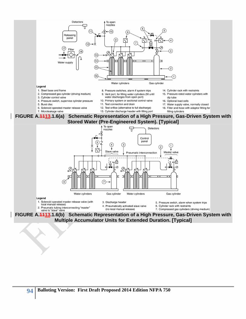
94 Balloting Version: First Draft Proposed 2014 Edition NFPA 750
FIGURE A.1113.1.6(a) Schematic Representation of a High Pressure, Gas-Driven System with
Stored Water (Pre-Engineered System). [Typical]
FIGURE A.1113.1.6(b) Schematic Representation of a High Pressure, Gas-Driven System with
Multiple Accumulator Units for Extended Duration. [Typical]
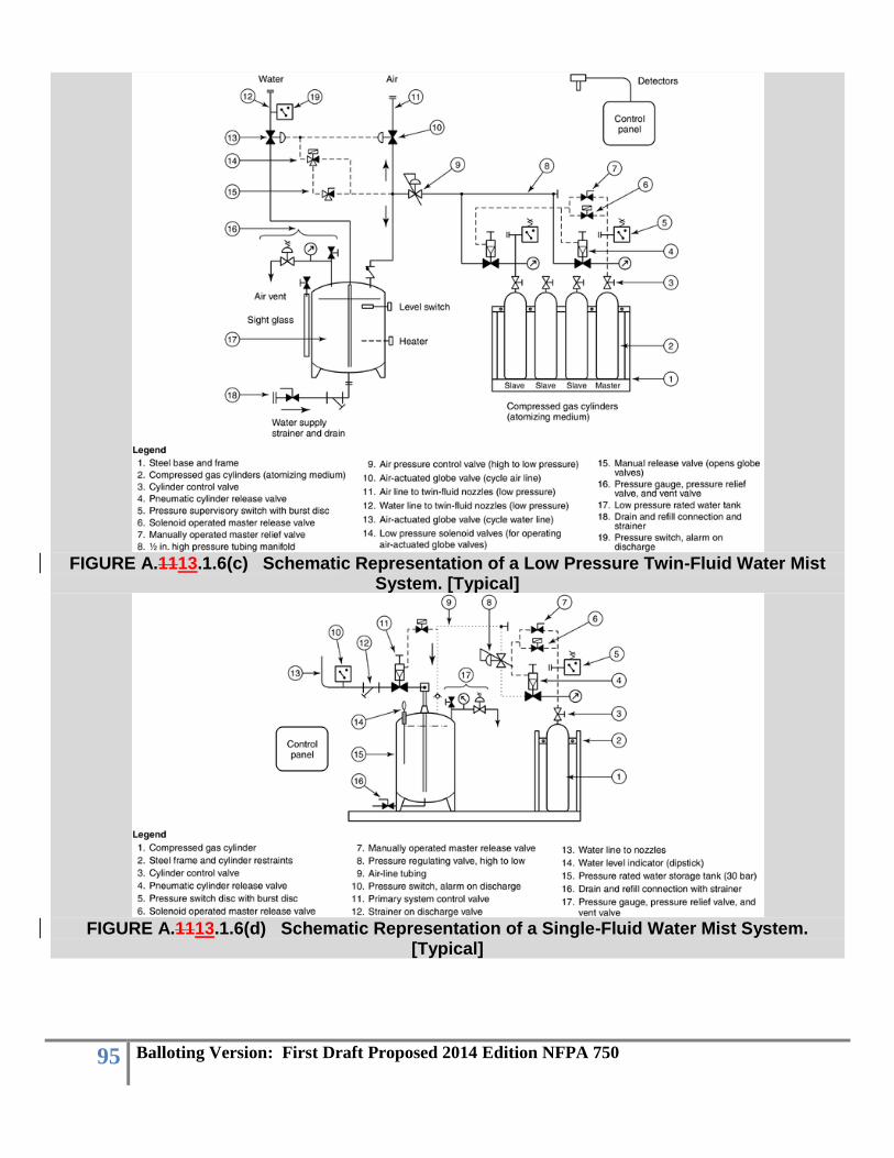
95 Balloting Version: First Draft Proposed 2014 Edition NFPA 750
FIGURE A.1113.1.6(c) Schematic Representation of a Low Pressure Twin-Fluid Water Mist
System. [Typical]
FIGURE A.1113.1.6(d) Schematic Representation of a Single-Fluid Water Mist System.
[Typical]
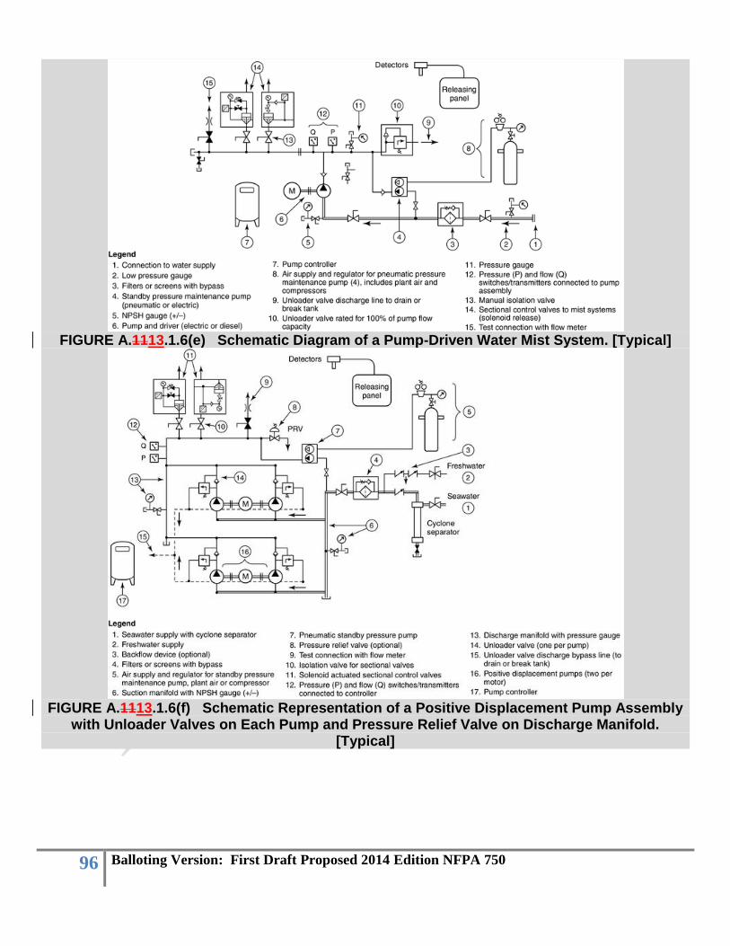
96 Balloting Version: First Draft Proposed 2014 Edition NFPA 750
FIGURE A.1113.1.6(e) Schematic Diagram of a Pump-Driven Water Mist System. [Typical]
FIGURE A.1113.1.6(f) Schematic Representation of a Positive Displacement Pump Assembly
with Unloader Valves on Each Pump and Pressure Relief Valve on Discharge Manifold. [Typical]
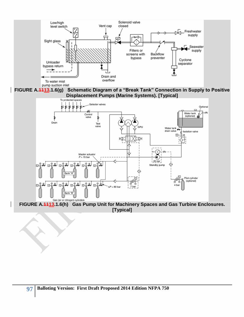
97 Balloting Version: First Draft Proposed 2014 Edition NFPA 750
FIGURE A.1113.1.6(g) Schematic Diagram of a “Break Tank” Connection in Supply to Positive
Displacement Pumps (Marine Systems). [Typical]
FIGURE A.1113.1.6(h) Gas Pump Unit for Machinery Spaces and Gas Turbine Enclosures.
[Typical]

98 Balloting Version: First Draft Proposed 2014 Edition NFPA 750
FIGURE A.1113.1.6(i) Gas Pump for Light Hazard Applications. [Typical]
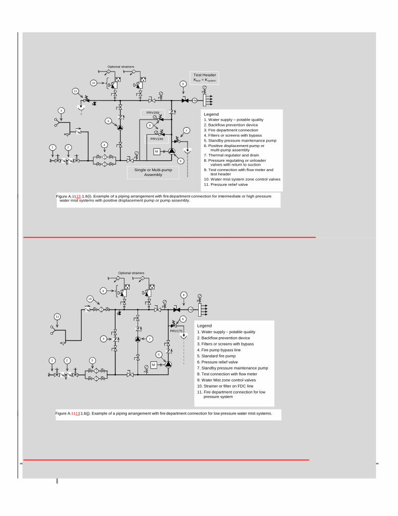
99 Balloting Version: First Draft Proposed 2014 Edition NFPA 750
Legend
1. Water supply – potable quality
2. Backflow prevention device
3. Fire department connection
4. Filters or screens with bypass
5. Standby pressure maintenance pump
6. Positive displacement pump or multi-pump assembly
7. Thermal regulator and drain
8. Pressure regulating or unloader valves with return to suction
9. Test connection with flow meter and test header
10. Water mist system zone control valves
11. Pressure relief valve
PRV250
M
PRV240
Test Header
Ktest = Ksystem
FM
1
8
7
9
5
6
2
10
4
Figure A.11.1.6(i). Example of a piping arrangement with fire department connection for intermediate or high pressure water mist systems with positive displacement pump or pump assembly.
Single or Multi-pump
Assembly
Optional strainers
3
11
Legend
1. Water supply – potable quality
2. Backflow prevention device
3. Filters or screens with bypass
4. Fire pump bypass line
5. Standard fire pump
6. Pressure relief valve
7. Standby pressure maintenance pump
8. Test connection with flow meter
9. Water Mist zone control valves
10. Strainer or filter on FDC line
11. Fire department connection for low pressure system
M
PRV175
1
8
7
5
2 3
Figure A.11.1.6(j). Example of a piping arrangement with fire department connection for low pressure water mist systems.
FM
10
6
4
11
Optional strainers
9
Figure A.1113
Figure A.1113

100 Balloting Version: First Draft Proposed 2014 Edition NFPA 750
A.1113.2 There are significant differences between how centrifugal fire pumps and positive displacement (PD) pumps operate. Methods for properly sizing centrifugal fire pumps in relation to the piping system and the design flow rate are well established in fire protection design practice. Fire protection systems designers are less familiar with PD pumps, however. The following discussion reviews some of the factors that are involved in selecting and sizing positive displacement pumps. For constant-speed drivers, the discharge rate of a PD pump is constant. Water mist systems, however, can have a variable demand flow, depending on how many nozzles open. The problem of using a constant discharge pump on a variable demand piping system is resolved by combining the positive displacement pump with an “unloader” valve and treating it as a composite unit. An unloader valve opens at a pre-set pressure and allows the unused portion of the pump discharge to bypass the distribution system. By including the unloader function, the PD pump “curve” can be plotted as a horizontal line, similar to a centrifugal pump curve. Important points to consider when selecting positive displacement pumps for a water mist system include the following: (1) The system head curve(s) (SHCs) for the water mist system under different nozzle-open
arrangements must be calculated and plotted with the PD pump curve. (2) The actual discharge from the system is determined by the intersection of the SHC and the pump
supply curve (i.e., the operating point). The operating point always has to be greater than the theoretical demand that is calculated for a system. The hydraulic calculations documentation should include a plot showing the SHCs, the pump supply curve (or line), the calculated demand point, and the operating point for each condition.
(3) In sizing the suction supply to the pump, and in calculating the total water storage required for a given duration of protection, the flow rate at the operating point has to be used, not the theoretical or calculated design flow rate.
First Revision No. 47:NFPA 750-2010 [FR 56: FileMaker]
A.14.1.3 When a water mist system operates in conjunction with other building systems, functions, or components, the final testing should be conducted simultaneously with those systems per NFPA 3, Recommended Practice on Commissioning and Integrated Testing of Fire Protection and Life Safety Systems.
First Revision No. 105:NFPA 750-2010 [FR 63: FileMaker]
A.14.1. 4 The acceptance test form is provided for the authority having jurisdiction. See Figure A.14.1.4.

101 Balloting Version: First Draft Proposed 2014 Edition NFPA 750

102 Balloting Version: First Draft Proposed 2014 Edition NFPA 750

103 Balloting Version: First Draft Proposed 2014 Edition NFPA 750
Figure A.14.1.4 Example Acceptance Test Form.
A.1214.2 All tests should be made by the contractor in the presence of an authorized inspector. When an inspector is not available, tests can be permitted to be witnessed by the owner or owner's representative. Before asking for final approval of the protective equipment, installing companies should furnish a written statement to the effect that the work covered by its contract has been completed, and all specified flushing of underground, lead-in, and system piping has been completed, successfully, together with specified hydrostatic pressure tests.
First Revision No. 49:NFPA 750-2010 [FR 75: FileMaker]
A.14.2.2.2.4 This practice is conducted to prevent damage to the valve during the hydrostatic test. A.1214.2.2.3 An allowance for a small drop in gauge pressure should be made to take into consideration the total volume of the system and environmental conditions. Smaller systems could see a slight drop in gauge pressure as a result of microscopic leaks that would not affect larger systems. Large systems could be affected by temperature changes that could raise or lower the hydrostatic pressure by small amounts. A.1214.2.3 The following caution should be heeded:
CAUTION: Pneumatic pressure testing creates a potential risk of injury to personnel in the area as a result of airborne projectiles if rupture of the piping system occurs. Prior to the pneumatic pressure test being conducted, the area should be evacuated and appropriate safeguards should be provided for test personnel.
A.1214.2.4.2.12 Proper shielding and grounding is particularly important if ac and dc wiring are combined in a common conduit or raceway.

104 Balloting Version: First Draft Proposed 2014 Edition NFPA 750
First Revision No. #:NFPA 750-2010 [FR 123: FileMaker]
A.1315.2.2 Table A.1315.2.2 indicates the recommended frequencies of inspection of typical components of water mist systems. See NFPA 25, Standard for the Inspection, Testing, and Maintenance of Water-Based Fire Protection Systems, for comprehensive requirements for inspection, testing, and maintenance of water mist systems.
Table A.1315.2.2 Maintenance of Water Mist Systems
Item Task Weekly Monthly Quarterly Semi-
Annually Annually Other
Water supply (general)
Check source pressure. X
Check source quality. X(first year)
X
Test source pressure, flow, quantity, duration.
X
Water storage tanks
Check water level (unsupervised).
X
Check water level (supervised).
X
Check sight glass valves are open.
X
Check tank gauges, pressure.
X
Check all valves, appurtenances.
X
Drain tank, inspect interior, and refill.
X
Inspect tank condition (corrosion).
X
Check water quality. X
Check water temperature. Extreme weather
Water storage cylinder (high pressure)
Check water level (load cells).
X
Check water level (unsupervised).
X
Check support frame/restraints.
X

105 Balloting Version: First Draft Proposed 2014 Edition NFPA 750
Check vent plugs at refilling.
X
Check cylinder pressure on discharge.
X
Inspect filters on refill connection.
X
Additive storage cylinders
Inspect general condition, corrosion.
X
Check quantity of additive agent.
X
Test quality of additive agent.
X
Test additive injection, full discharge test.
X
Water recirculation tank
Check water level (unsupervised).
X
Check water level (supervised).
X
Inspect supports, attachments.
X
Test low water level alarm. X
Check water quality, drain, flush and refill.
X
Test operation of float operated valve.
X
Test pressure at outlet during discharge.
X
Test backflow prevention device (if present).
X
Inspect and clean filters, strainers, cyclone separator.
X
Compressed gas cylinders
Inspect support frame and cylinder restraints.
X
Check cylinder pressure (unsupervised).
X
Check cylinder pressure (supervised).
X

106 Balloting Version: First Draft Proposed 2014 Edition NFPA 750
Check cylinder control valve is open.
X
Check cylinder capacity and pressure rating.
X
Check cylinder compliance specification.
X
Confirm compressed gas meets specifications (moisture, cylinder pressure).
X
Hydrostatic test cylinders. 5–12 years
Plant air, compressors, and receivers
Check air pressure (unsupervised).
X
Check air pressure (supervised).
X
Start compressor. X
Check compressor/receiver capacity, changes.
X
Check compressed air moisture content.
X
Clean filters, moisture traps.
X
Test full capacity, duration, and any changes in other demands.
X
Pumps and drivers
Inspection, testing, and maintenance shall be in accordance with the requirements of NFPA 20, Standard for the Installation of Stationary Pumps for Fire Protection, and NFPA 25, Standard for the Inspection, Testing, and Maintenance of Water-Based Fire Protection Systems.
X X X X X
Standby pump
Inspect moisture trap, oil injection (pneumatic).
X
Check compressed gas X
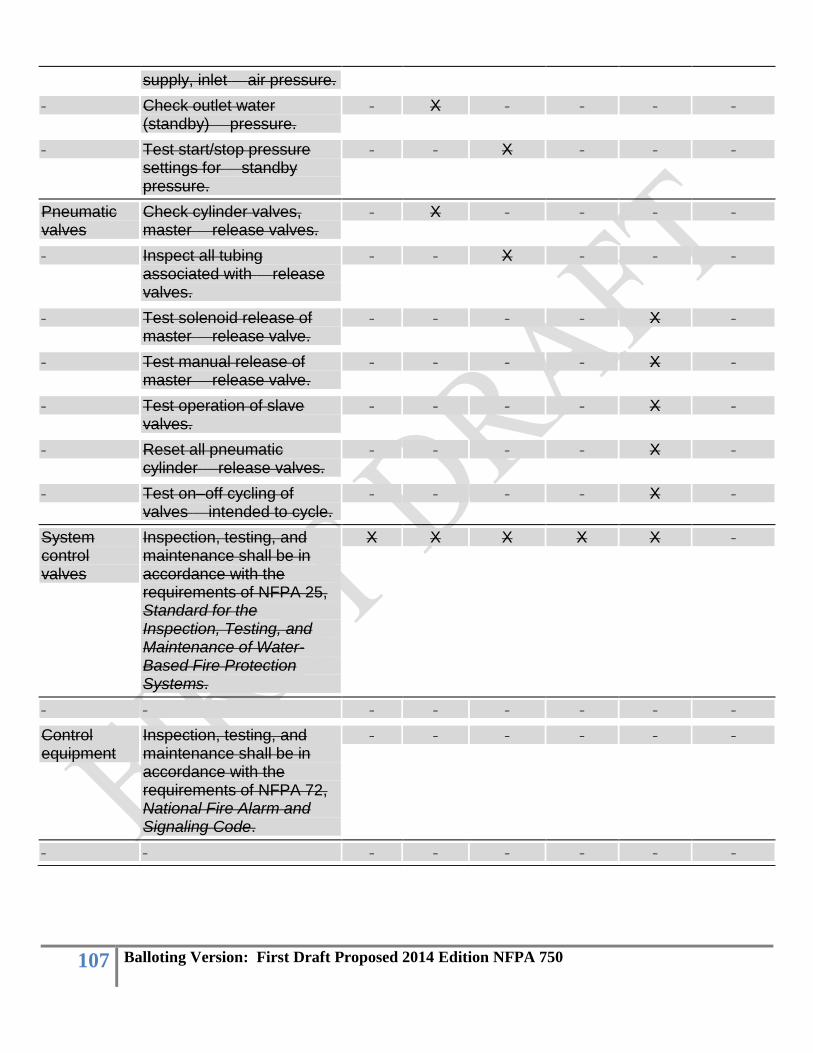
107 Balloting Version: First Draft Proposed 2014 Edition NFPA 750
supply, inlet air pressure.
Check outlet water (standby) pressure.
X
Test start/stop pressure settings for standby pressure.
X
Pneumatic valves
Check cylinder valves, master release valves.
X
Inspect all tubing associated with release valves.
X
Test solenoid release of master release valve.
X
Test manual release of master release valve.
X
Test operation of slave valves.
X
Reset all pneumatic cylinder release valves.
X
Test on–off cycling of valves intended to cycle.
X
System control valves
Inspection, testing, and maintenance shall be in accordance with the requirements of NFPA 25, Standard for the Inspection, Testing, and Maintenance of Water-Based Fire Protection Systems.
X X X X X
Control equipment
Inspection, testing, and maintenance shall be in accordance with the requirements of NFPA 72, National Fire Alarm and Signaling Code.
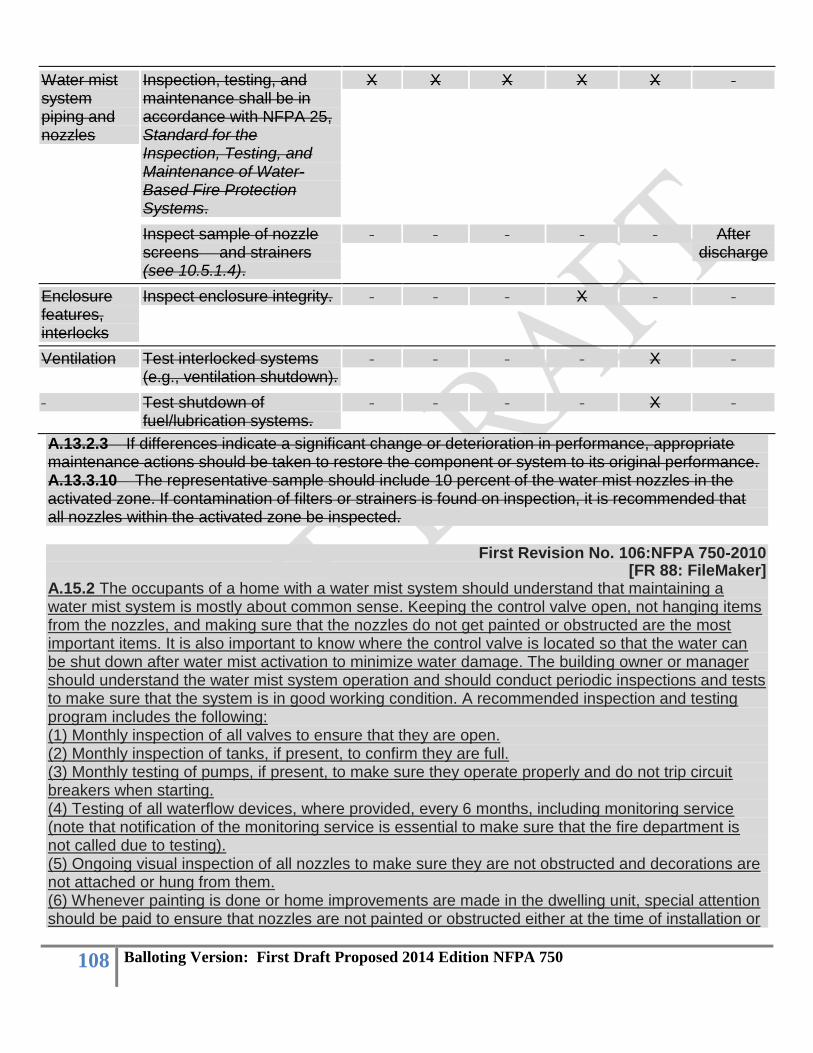
108 Balloting Version: First Draft Proposed 2014 Edition NFPA 750
Water mist system piping and nozzles
Inspection, testing, and maintenance shall be in accordance with NFPA 25, Standard for the Inspection, Testing, and Maintenance of Water-Based Fire Protection Systems.
X X X X X
Inspect sample of nozzle screens and strainers (see 10.5.1.4).
After discharge
Enclosure features, interlocks
Inspect enclosure integrity. X
Ventilation Test interlocked systems (e.g., ventilation shutdown).
X
Test shutdown of fuel/lubrication systems.
X
A.13.2.3 If differences indicate a significant change or deterioration in performance, appropriate maintenance actions should be taken to restore the component or system to its original performance. A.13.3.10 The representative sample should include 10 percent of the water mist nozzles in the activated zone. If contamination of filters or strainers is found on inspection, it is recommended that all nozzles within the activated zone be inspected.
First Revision No. 106:NFPA 750-2010 [FR 88: FileMaker]
A.15.2 The occupants of a home with a water mist system should understand that maintaining a water mist system is mostly about common sense. Keeping the control valve open, not hanging items from the nozzles, and making sure that the nozzles do not get painted or obstructed are the most important items. It is also important to know where the control valve is located so that the water can be shut down after water mist activation to minimize water damage. The building owner or manager should understand the water mist system operation and should conduct periodic inspections and tests to make sure that the system is in good working condition. A recommended inspection and testing program includes the following: (1) Monthly inspection of all valves to ensure that they are open. (2) Monthly inspection of tanks, if present, to confirm they are full. (3) Monthly testing of pumps, if present, to make sure they operate properly and do not trip circuit breakers when starting. (4) Testing of all waterflow devices, where provided, every 6 months, including monitoring service (note that notification of the monitoring service is essential to make sure that the fire department is not called due to testing). (5) Ongoing visual inspection of all nozzles to make sure they are not obstructed and decorations are not attached or hung from them. (6) Whenever painting is done or home improvements are made in the dwelling unit, special attention should be paid to ensure that nozzles are not painted or obstructed either at the time of installation or

109 Balloting Version: First Draft Proposed 2014 Edition NFPA 750
during subsequent redecoration. When painting is being done in the vicinity of nozzles, every nozzle should be covered with a bag, which should be removed immediately after painting is finished. A.1416.1.2 Reference is made to standards developed by the International Maritime Organization. A.1416.1.5 Refer to ASTM F 1547, Standard Guide Listing Relevant Standards and Publications for Commercial Shipbuilding, and ANSI/ASME B31.1, Power Piping Code. A.1416.1.6 Consideration should be given to physically separating the pumping units. It is recommended that not less than 40 percent of the maximum system's flow demand be provided from any single pumping location. Consideration should be given to using designs incorporating looped systems or arrangements that allow a section to be taken out of service for maintenance. When pumps from another onboard fire protection system, such as fire main pumps, are used to satisfy this requirement, they should be sized to simultaneously supply both systems. A.1416.1.8 When applying NVIC 9-97, Guide to Structural Fire Protection, copper pipe is not considered heat sensitive; however, brazed joints are. Therefore, there are limitations on the proximity of brazed joints to deck and bulkhead penetrations. In general, brazed joints should be 300 mm or more from the penetration. A.1416.1.9.4 A representative arrangement of the shore connections is shown in Figure A.17.7.3.12.2(1) of NFPA 13, Standard for the Installation of Sprinkler Systems. The international shore connection dimensions are shown in Figure A.17.1.3(4) of NFPA 13. A.1416.1.10 The preferred arrangement for pump flow measurement is given in Figure A.17.7.3.13 of NFPA 13. A.1416.2.2 The charge of air or gas for the hydropneumatic tank should be such that the last gallon of water in the tank leaves the tank at the system demand pressure. The tank can be arranged with an internal charge of gas or an external gas supply with a regulator. If an internal charge of air or gas is provided, the equation P1V1 = P2V2 should be used to calculate the required gas pressure. In all
cases, arrangements should be provided to avoid filling the system piping with gas when the hydropneumatic tank is empty. Under normal circumstances, the pump should be arranged to provide water at a pressure greater than the gas pressure before the tank is empty. The reference to SOLAS requires an arrangement to prevent seawater from entering the hydropneumatic tank. A.1416.2.3 An example of an acceptable arrangement is manual operation of a sea chest valve (outside the protected space) to allow continued operation using seawater following the 30-minute stored freshwater operation. A.1416.2.7 Deluge or antifreeze systems could be needed where protected areas are subject to freezing. Piping subject to freezing could be subject to clogging by ice. A.1416.2.14 If combustibles are present such that they constitute a threat, the space should be protected. One example would be the presence of large bundles of exposed computer or electrical cable. Typical amounts of lighting or control cabling should not be considered to constitute a fire threat. A.1416.3.2.1 Designers should take into account the flash points of all stored liquids when planning a system. Water mist systems protecting flammable liquid lockers storing liquids with a flash point below the ambient water temperature could experience a flammable vapor explosion if the water mist system does not fully extinguish the fire. A.1416.3.3 It is assumed that water mist systems for flammable liquid hazards and compartments require the simultaneous release of water mist from all nozzles in groups of nozzles in the manner of total flooding systems. If systems that operate using individually, thermally actuated nozzles are shown by test to have the capability of extinguishing the variety of fires of the machinery space fire test protocol, then manual actuation should cause sufficient nozzles to operate to achieve protection no less effective than that demonstrated in the test protocol.

110 Balloting Version: First Draft Proposed 2014 Edition NFPA 750
A.1416.3.3.2 An example of an acceptable arrangement is manual operation of a sea chest valve (outside the protected space) to allow continued operation on seawater following the 30-minute stored freshwater discharge. A.1416.3.4 Time delays are optional on water mist systems. A.1416.3.5.6 For systems that cycle, the 15-minute requirement represents 15 minutes at the maximum flow rate, as if the duty cycle were 100 percent for 15 minutes. Examples include the following: (1) Constant — such as supplied by a pump (2) Decaying — occurs when a pressure cylinder discharges (3) Uniform cycling — when a timing device is used to periodically change the pressure or the flow
rate (4) Nonuniform cycling — such as when a heat detector cycles a system on and off A.1416.3.5.7 Following the depletion of the 30-minute freshwater supply, if continuous seawater operation is provided at a pressure other than that used to successfully perform the machinery space fire tests of 14.3.2.116.3.2.1, the nozzle spray characteristics should be capable of maintaining the cooling of the compartment. Flow rates need not equal those of Safety of Life at Sea (SOLAS) Resolution 10, Fixed Pressure Water Spray Systems. A.1416.3.6 It is recommended that on passenger ships designed to carry more than 36 persons and on all tank vessels, both the main and emergency sources of power should be from outside the protected space. A.1416.4 The ship's crew will be called upon to inspect, test, maintain, react to, and use some or all parts of the water mist fire suppression system. Therefore, the crew is an integral part of the system. Historically, the crew is the part of the system that system designers and installers have little or no control over. Much of the system will be designed to maintain readiness and operate without human intervention. However, system readiness and operation during an emergency will always involve human interaction with the system. Systems should include design and component features incorporating human factors so as to maximize readiness and utility during a fire. A1416.5 Examples of water mist system design features unique to combatant vessels are as follows: (1) Extended-duration water supply (2) Dedicated freshwater storage tanks (3) Dual-source water supply for combat redundancy (4) Enhanced shock and vibration resistance (5) Dual system activation means (6) Corrosion resistance (7) Two-source power supply with automatic bus transfer feed (8) Combat survivability features (9) Increased structural integrity for piping valves, fittings, and hangers (10) Redundancy and separation of controls and valves (11) Augmentation with foam bilge sprinklering (12) Full-flow end-of-line test fittings (13) Ventilation interlock (14) Remote tank-level monitoring
Annex B Research Summary This annex is not a part of the recommendations of this NFPA document but is included for informational purposes only.
B.1 Water Mist Droplet Size Characterization and Measurement.

111 Balloting Version: First Draft Proposed 2014 Edition NFPA 750
A key mechanism in the successful use of water mist fire protection systems is the increased surface area per unit water volume afforded with the generation and application of small droplets. The increased surface area dramatically increases the rate of heat transfer from the fire to the water mist droplet, cooling the combustion reaction and diluting the oxygen concentration with the generation of water vapor in the vicinity of the fire. It is important to characterize the droplet size distribution produced in listed nozzles for use in the future design and application of water mist systems. It will be valuable in assessing the ability of water mist droplets to control, suppress, and extinguish fires of all types and sizes. Presently, three basic techniques are used for the characterization of droplet sizes in a nozzle spray: optical imaging; diffraction; and Doppler refraction. The first technique uses optical technology to photograph or electronically image the droplets in a small volume of the mist. The image is then analyzed to determine the size distribution of droplets on the image. The second technique uses a collimated light source passed through the water mist. The water droplets diffract the light into a series of detectors. The angle of diffraction is a function of the size of the droplets in the light beam. By measuring the relative light intensities on the detectors, the distribution of droplet sizes can be determined. The third technique uses a pair of crossed laser beams to generate a small sample volume through which the water droplets pass. The laser light is refracted inside the droplets and detected off-axis. The detector signal is processed to define the droplet size and velocity distributions. All three techniques are automated in most commercially available measuring instruments, sampling tens of thousands of droplets for the determination of a droplet size distribution. The instruments typically divide the sizes into categories, or “bins,” defined by a range of diameters assigned to each bin. Results are then reported as the number of droplets in each bin or as a fractional distribution of number count or total volume in each bin. Most commercially available measuring instruments also present additional measurements of size distribution significant to the characterization of a water mist. One of these is the Sauter Mean Diameter (SMD), defined as the total volume of the measured droplet population divided by the total surface area of the population. SMD is often used as a characteristic dimension when mass transfer (including phase change) is the key process. Another important measurement is the maximum diameter at which a specified fraction of the total volume is accumulated. For example, Dv0.10 represents the diameter at which 10 percent of the total
volume of the water mist is contained in droplets at or less than the specified diameter. By this definition, Dv0.10 represents the volumetric median diameter; that is, 50 percent of the total volume
of the total water mist is contained in droplets equal to or less than this diameter, and 50 percent is contained in droplets of greater diameter.
Annex C Examples of Fire Test Protocols This annex is not a part of the recommendations of this NFPA document but is included for informational purposes only.
First Revision No. 89:NFPA 750-2010
[FR 110: FileMaker] C.1 General. In the absence of a generalized design method based on engineering first principles, water mist systems must be listed for specific hazards and protection objectives. It is the intent of NFPA 750 that such listings be obtained through full- scale fire tests and system component evaluations conducted by internationally recognized laboratories to demonstrate that performance objectives can be met. New potential applications of water mist arise continuously, for which ad hoc

112 Balloting Version: First Draft Proposed 2014 Edition NFPA 750
test procedures have been developed. Only a limited number of such ad hoc fire test protocols meet the intent of this standard, which is as follows: (1) Test protocols should be based on a fire protection engineering evaluation of the fire hazard, the compartment conditions, and the performance objectives for the system. (2) Test protocols should be developed, carried out, and interpreted by internationally recognized fire testing laboratories. Only test protocols developed in that manner are recognized as the basis of a listing. The full listing consists of an approval report describing the results of the performance -based fire testing and of the component evaluations, and a the manufacturer’s design installation and maintenance manual. The nozzle characteristics; spacing between nozzles; distances from ceilings, walls, or obstructions; minimum nozzle operating pressures; and water supply requirements are all established by the approval report. C.1.1 Testing and certification laboratories should extend their system evaluation to components other than the nozzle, based on a customized evaluation or review. Where such evaluations are done, details of the evaluation criteria should be included in the approval report. It is the intent of NFPA 750 that all components not included in the approval report be listed or approved equipment. However, some types of equipment utilized in water mist systems but not fully evaluated in the approval process are new to fire protection applications and no prior listings exist. An example includes the piston-type pumps used in high pressure systems. Such gaps in the approval process are gradually being addressed through changes to other standards (such as NFPA 20, Standard for the Installation of Stationary Pumps for Fire Protection, 2003 edition) and by case-by-case evaluations conducted by a recognized testing laboratory.
First Revision No. 63:NFPA 750-2010 [FR 62: FileMaker]
C.1.2 Table C.1.2 identifies several organizations with wide international recognition that currently develop or administer test protocols for water mist fire suppression systems. The following sections provide brief descriptions of the scope of application and the acceptance criteria of the test protocols that are the basis for the 1998 listings for water mist systems. The testing laboratories can add or subtract certain fire tests, at their discretion, based on their interpretation of the system performance limits. The reader should refer to the original test protocols for complete test details.
Table C.1.2 Table C.1.2 Internationally Recognized Agencies with Published Fire Test Protocols for Water Mist Fire Protection Systems
Agency Water Mist Fire Test Protocol
1. International Maritime Organization, London, UK
MSC/Circ.1165, Revised guidelines for the approval of equivalent water-based fire-extinguishing systems for machinery spaces and cargo pump-rooms. Appendix B “Test method for fire testing equivalent water-based fire-extinguishing systems for machinery spaces of category A and cargo pump-rooms”, June 2005
as amended in MSC.1./Circ.1237, Amendments to the revised guidelines for the approval of equivalent water-based fire-extinguishing systems for machinery spaces and cargo pump-rooms (MSC/Circ.1165), October 2007
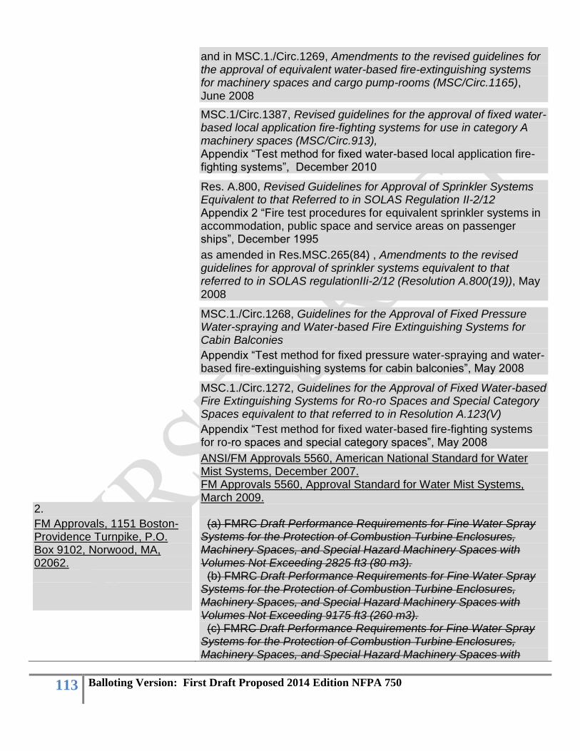
113 Balloting Version: First Draft Proposed 2014 Edition NFPA 750
and in MSC.1./Circ.1269, Amendments to the revised guidelines for the approval of equivalent water-based fire-extinguishing systems for machinery spaces and cargo pump-rooms (MSC/Circ.1165), June 2008
MSC.1/Circ.1387, Revised guidelines for the approval of fixed water-based local application fire-fighting systems for use in category A machinery spaces (MSC/Circ.913), Appendix “Test method for fixed water-based local application fire-fighting systems”, December 2010
Res. A.800, Revised Guidelines for Approval of Sprinkler Systems Equivalent to that Referred to in SOLAS Regulation II-2/12 Appendix 2 “Fire test procedures for equivalent sprinkler systems in accommodation, public space and service areas on passenger ships”, December 1995
as amended in Res.MSC.265(84) , Amendments to the revised guidelines for approval of sprinkler systems equivalent to that referred to in SOLAS regulationIIi-2/12 (Resolution A.800(19)), May 2008
MSC.1./Circ.1268, Guidelines for the Approval of Fixed Pressure Water-spraying and Water-based Fire Extinguishing Systems for Cabin Balconies
Appendix “Test method for fixed pressure water-spraying and water-based fire-extinguishing systems for cabin balconies”, May 2008
MSC.1./Circ.1272, Guidelines for the Approval of Fixed Water-based Fire Extinguishing Systems for Ro-ro Spaces and Special Category Spaces equivalent to that referred to in Resolution A.123(V)
Appendix “Test method for fixed water-based fire-fighting systems for ro-ro spaces and special category spaces”, May 2008
2.
FM Approvals, 1151 Boston-Providence Turnpike, P.O. Box 9102, Norwood, MA, 02062.
ANSI/FM Approvals 5560, American National Standard for Water Mist Systems, December 2007. FM Approvals 5560, Approval Standard for Water Mist Systems, March 2009. (a) FMRC Draft Performance Requirements for Fine Water Spray Systems for the Protection of Combustion Turbine Enclosures, Machinery Spaces, and Special Hazard Machinery Spaces with Volumes Not Exceeding 2825 ft3 (80 m3). (b) FMRC Draft Performance Requirements for Fine Water Spray Systems for the Protection of Combustion Turbine Enclosures, Machinery Spaces, and Special Hazard Machinery Spaces with Volumes Not Exceeding 9175 ft3 (260 m3). (c) FMRC Draft Performance Requirements for Fine Water Spray Systems for the Protection of Combustion Turbine Enclosures, Machinery Spaces, and Special Hazard Machinery Spaces with

114 Balloting Version: First Draft Proposed 2014 Edition NFPA 750
Volumes Exceeding 9175 ft3 (260 m3). (d) FMRC Draft Performance Requirements for Fine Water Spray Systems for the Protection of Light Hazard Occupancies. (e) FMRC Draft Performance Requirements for Fine Water Spray Systems for the Protection of Wet Benches and Other Processing Equipment. (f) FMRC Draft Performance Requirements for Water Mist Systems for Local Application System Protection (a) Fire Tests for Water Mists Systems for the Protection of Combustion Turbines with Volumes up to, and including, 2825 ft3 (80 m3) (b) Fire Tests for Water Mists Systems for the Protection of Combustion Turbines with Volumes up to, and including, 9175 ft3 (260 m3) (c) Fire Tests for Water Mists Systems for the Protection of Combustion Turbines with Volumes Exceeding 9175 ft3 (260 m3) (d) Fire Tests for Water Mists Systems for the Protection of Wet Benches and Other Similar Processing Equipment (e) Fire Tests for Water Mists Systems for the Protection of Local Applications (f) Fire Tests for Water Mists Systems for the Protection of Industrial Oil Cookers (g) Fire Tests for Water Mists Systems for the Protection of Computer Room Sub Floors (h) General Requirements (i) Performance Requirements (Water Mist Nozzles and System Components) (j) Operations Requirements FM Approvals Class Number 5560, Approval Standard for Water Mist Systems (a) Fire Tests for Water Mists Systems for the Protection of Machinery in Enclosures with Volumes not Exceeding 2825 ft3 (80 m3) (b) Fire Tests for Water Mists Systems for the Protection of Combustion Turbines in Enclosures with Volumes not Exceeding 2825 ft3 (80 m3) (c) Fire Tests for Water Mists Systems for the Protection of Machinery in Enclosures with Volumes not Exceeding 9175 ft3 (260 m3) (d) Fire Tests for Water Mists Systems for the Protection of Combustion Turbines in Enclosures with Volumes not Exceeding 9175 ft3 (260 m3)
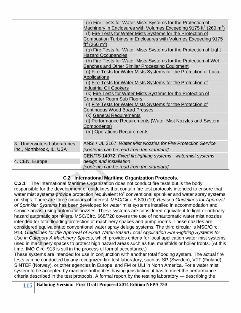
115 Balloting Version: First Draft Proposed 2014 Edition NFPA 750
(e) Fire Tests for Water Mists Systems for the Protection of Machinery in Enclosures with Volumes Exceeding 9175 ft3 (260 m3) (f) Fire Tests for Water Mists Systems for the Protection of Combustion Turbines in Enclosures with Volumes Exceeding 9175 ft3 (260 m3) (g) Fire Tests for Water Mists Systems for the Protection of Light Hazard Occupancies (h) Fire Tests for Water Mists Systems for the Protection of Wet Benches and Other Similar Processing Equipment (i) Fire Tests for Water Mists Systems for the Protection of Local Applications (j) Fire Tests for Water Mists Systems for the Protection of Industrial Oil Cookers (k) Fire Tests for Water Mists Systems for the Protection of Computer Room Sub Floors. (l) Fire Tests for Water Mists Systems for the Protection of Continuous Wood Board Presses (k) General Requirements (l) Performance Requirements (Water Mist Nozzles and System Components) (m) Operations Requirements
3. Underwriters Laboratories Inc., Northbrook, IL, USA
ANSI / UL 2167, Water Mist Nozzles for Fire Protection Service
[contents can be read from the standard]
4. CEN, Europe CEN/TS 14972, Fixed firefighting systems - watermist systems - design and installation [contents can be read from the standard]
C.2 International Maritime Organization Protocols.
C.2.1 The International Maritime Organization does not conduct fire tests but is the body responsible for the development of guidelines that contain fire test protocols intended to ensure that water mist systems provide protection “equivalent to” conventional sprinkler and water spray systems on ships. There are three circulars of interest. MSC/Circ. A.800 (19) Revised Guidelines for Approval of Sprinkler Systems has been developed for water mist systems installed in accommodation and service areas, using automatic nozzles. These systems are considered equivalent to light or ordinary hazard automatic sprinklers. MSC/Circ. 668/728 covers the use of nonautomatic water mist nozzles intended for total flooding protection of machinery spaces and pump rooms. These nozzles are considered equivalent to conventional water spray deluge systems. The third circular is MSC/Circ. 913, Guidelines for the Approval of Fixed Water-Based Local Application Fire-Fighting Systems for Use in Category A Machinery Spaces, which provides criteria for local application water mist systems used in machinery spaces to protect high hazard areas such as fuel manifolds or boiler fronts. (At this time, IMO Circ. 913 is still in the process of formal acceptance.) These systems are intended for use in conjunction with another total flooding system. The actual fire tests can be conducted by any recognized fire test laboratory, such as SP (Sweden), VTT (Finland), SINTEF (Norway), or other agencies in Europe, and FM or ULI in North America. For a water mist system to be accepted by maritime authorities having jurisdiction, it has to meet the performance criteria described in the test protocols. A formal report by the testing laboratory — describing the
116 Balloting Version: First Draft Proposed 2014 Edition NFPA 750
outcome of the fire tests and certifying that the system performance met the performance limits of the test protocol — along with the evaluation of components and system hardware, constitutes the “basis” for approval of the system by marine regulatory authorities. The IMO circulars include both fire testing protocols and component testing standards for water mist nozzles. C.2.2 Copies of MSC/Circ. A.800 (19) and MSC/Circ. 668/728 can be obtained from the International Maritime Organization, 4 Albert Embankment, London SE1 7SR, or ordered online at www.imo.org. The circulars are published in the International Code for the Application of Fire Test Procedures (FTP Code). This document can be found in the Marine Technology category under the publications section of the IMO website. C.2.3 Machinery Compartments. C.2.3.1 “Test Method for Equivalent Sprinkler System for Class 1, 2, and 3, Category A Machinery
Compartments” addresses liquid fuel fires in machinery compartments of 500 m3, main diesel
machinery in spaces up to 3000 m3, and larger volume diesel machinery spaces on oil tankers and container ships. The test compartment has a 2 m × 2 m ventilation opening in one wall. A mock-up of a large diesel engine with associated bilge space is constructed in the center of the test enclosure. Liquid fuels include low and high pressure fuel lines, lubrication oil lines, and hydraulic oil lines, with spray, spill, and pool fires. Some of the fires are shielded from direct water spray by steel plates. Thirteen fire scenarios are described: eight use commercial fuel oil or light diesel oil (“high” flash point fuels), four use heptane fuel (“low” flash point fuels), and one involves a wood crib and heptane igniter. Spray, pool, and spill fires are tested. C.2.3.2 The IMO machinery space water mist system has to extinguish all test fires, including small hidden bilge fires, and prevent reignition. This test protocol requires full extinguishment of all fires. Systems that have passed the IMO machinery space test protocol are permitted to utilize combinations of total flooding ceiling nozzles and screening nozzles over the ventilation opening, as well as the addition of foaming agent to the water supply (for hidden fires in the bilge areas). Systems can also incorporate a separate bilge protection system. Nozzles are generally of the nonautomatic type (open), and the systems are permitted to be activated manually. Water supply is provided using stored water in pressurized cylinders to provide the first minute of operation without electric power. After one minute, it is assumed that pumps will be started to meet the waterflow demand for up to 30 minutes, either from stored freshwater or from seawater sources. C.2.4 Cabin and Corridor Fires. C.2.4.1 Test Protocol for Equivalent Sprinkler Systems for Cabin and Corridor Fires. The test protocol describes fire tests involving polyether mattresses with cotton covers in sleeping quarters on
ships. Compartment sizes range from 16 m2 to 25 m2 and up to 52 m2 in luxury cabins. The luxury cabin test includes a wood crib and simulated furniture, which is the residential fuel package. Nozzles are of the automatic type (activated by heat in the manner of a sprinkler). The system is tested with cabin and corridor nozzles. In one test, cabin nozzles are disabled, and the corridor nozzles have to prevent fire from spreading along the corridor. C.2.4.2 It is important to note that, unlike the machinery space tests, pass/fail criteria for the cabin and corridor fires are not based on full extinguishment. The cabin and corridor fires have to be controlled by the water mist system for up to 10 minutes, after which time the test operators manually extinguish any remaining fire. The average damage to the mattresses over all tests must not exceed 35 percent, with no test resulting in losses greater than 50 percent of the original material. C.2.5 Water-Based Fire Extinguishing Systems in Accommodation and Public Space Areas Onboard Ships. C.2.5.1 The public space tests evaluate the ability of water mist to control fires in open public spaces on ships, with ceiling heights of one or two deck heights (2.5 m or 5.0 m, respectively). The
117 Balloting Version: First Draft Proposed 2014 Edition NFPA 750
open public space tests involve simulated couches with cotton-covered polyether mattresses on steel frames, representing a lounge-type setting in the center of large rooms. Tests are done under one, between two, and between four nozzles, at either 2.5 m or 5.0 m ceiling height. Nozzles are of the automatic type (thermally activated). A corner fire scenario is included, which involves fire in the corner of a room with combustible wall and ceiling panels. The water mist system has to prevent fire spread to target couches and limit ceiling temperatures. The corner test includes a disabled nozzle, such that the fire control is achieved through operation of the functioning nozzles. C.2.5.2 The water mist system has to control the fire for 10 minutes, after which time the operators manually extinguish any remaining fire. Damage to the mattresses has to be within prescribed limits, with the average for all tests of 35 percent or less, with no single test exceeding 50 percent damage. C.2.5.3 Shopping and storage areas on ships involve much higher fuel loading than encountered in open public areas. The IMO test protocol for shopping and storage areas involves plastic cups in cardboard cartons (standard Group A plastic commodity) stacked 1.5 m high in the same array as used for ordinary hazard sprinkler fire tests. Target arrays of empty cartons surround the main fuel piles. C.2.5.4 The fire in the stacked boxes has to be controlled for up to 10 minutes, after which time the operators manually extinguish the remaining fire. Fire cannot spread to the target boxes, nor can charring of any of the target arrays occur. In any one test, damage to the boxes and plastic cups in the fire source cartons cannot exceed 50 percent. This test fire represents a challenge to any water-based suppression systems, including conventional sprinklers. C.2.6 IMO Component Standards. C.2.6.1 IMO MSC/668, in Appendix A, “Component Manufacturing Standards of Equivalent Water-Based Fire Extinguishing Systems,” describes tests for evaluating water mist nozzles. Rigorous tests are performed on the nozzle to determine hydraulic characteristics, water flux and drop size distributions, responsiveness of thermal sensing elements (for automatic nozzles), structural strength, resistance to impact, corrosion, and clogging, and so forth. The tests described in this annex are the basis for the component evaluations conducted under UL 2167, Standard for Water Mist Nozzles for Fire Protection Service. Components other than the nozzle, such as water or gas storage cylinders, pump, control valves, pressure reducing valves, or special actuators, are not part of the IMO MSC/Circ. 668, Appendix A protocol.
First Revision No. 90:NFPA 750-2010 [FR 111: FileMaker]
C.2.7 Local Application Systems for Machinery Spaces. The appendix to MSC/Circ. 913 IMO MSC/Circ. 913, Guidelines for the Approval of Fixed Water-Based Local Application Fire-Fighting Systems for Use in Category A Machinery Spaces, indicates that local application systems are intended to provide additional, localized fire suppression in areas where there is a possibility of flammable or combustible liquids contacting heated surfaces, such as the fire hazard portions of internal combustion machinery used for the a ship’s main propulsion and power generation, boiler fronts, the fire hazard portions of incinerators, and purifiers for heated fuel oil within Category A machinery spaces. The system is intended as a supplement to the required total flooding system and will allow immediate, manually activated fire control without the necessity of engine shutdown, personnel evacuation, shutting down of forced ventilation fans, or the sealing of the space. In the case of periodically unattended machinery spaces, the fire-fighting system shall have both automatic and manual release capabilities. The appendix to MSC/Circ. 913 contains the fire test protocol used to evaluate the water mist nozzles for this application. The test method verifies the design criteria for vertical and horizontal grids of nozzles. The test method is intended to evaluate maximum nozzle spacing, minimum and maximum
118 Balloting Version: First Draft Proposed 2014 Edition NFPA 750
distances from the nozzle to the hazard, the minimum nozzle flow rate, and minimum and maximum nozzle operating pressures. Component testing standards are taken from those listed in IMO/MSC/Circ 1165.IMO MSC/Circ. 668/728. The fire tests are to be conducted in an open area of at least 100 m2. Both 1 MW and 6 MW spray fires using light diesel oil as the fuel source are included in the protocol.
First Revision No. 64:NFPA 750-2010 [FR 64: FileMaker]
C.3 Factory Mutual Research Corporation FM Approvals Fire Test Protocols. C.3.1 General. FM Approvals Class Number 5560, Approval Standard for Water Mist Systems, contains comprehensive test requirements for evaluating a complete water mist system, including the water mist nozzles, water mist system components: design, installation, and operations manual(s); hydraulic calculation method,-; and fire test protocols for the applications in C.3.2 through C.3.1.3. Similar fire test protocols can be found in ANSI/FM Approvals 5560, American National Standard for Water Mist Systems. C.3.2 Machinery in Enclosures with Volumes Not Exceeding 80 m3 (2825 ft3). This application includes enclosures with machinery such as internal combustion engines, oil pumps, oil tanks, fuel filters, generators, transformer vaults, gear boxes, drive shafts, lubrication skids, diesel engine–driven generators, and other similar equipment using liquid hydrocarbon fuel and/or hydraulic, heat transfer, and lubrication fluids; enclosures with incidental use or storage of hydrocarbon ignitible liquids (also known as flammable liquids) of not more than two 55 gal (208 L) drums. All hazards included under the scope of this total flooding application are to be protected for a minimum of twice the longest time to extinguish the test fires, the time to shut down process equipment, or 10 minutes, whichever is greatest. C.3.3 Combustion Turbines in Enclosures with Volumes Not Exceeding 80 m3 (2825 ft3). Combustion turbines included under the scope of this total flooding application are to be protected for a minimum of twice the longest time to extinguish the test fires, turbine rundown time (including the time that the turbine surfaces are above the auto-ignition temperature of the lubricating fluid), the time to shut down process equipment, or 10 minutes, whichever is greatest. Consultation with FM Global Property Loss Prevention Data Sheet Number 7-79, Fire Protection for Combustion Turbine Installations, is required for installation of these systems. C.3.4 Machinery in Enclosures with Volumes Not Exceeding 260 m3 (9175 ft3). This application includes rooms with machinery such as oil pumps, oil tanks, fuel filters, generators, transformer vaults, gear boxes, drive shafts, lubrication skids, diesel engine–driven generators, and other similar machinery using fuel and/or lubrication fluids with volatilities less than or equal to light diesel. All hazards included under the scope of this total flooding application are to be protected for a minimum of twice the longest time to extinguish the test fires, the time to shut down process equipment, or 10 minutes, whichever is greatest. C.3.5 Combustion Turbines in Enclosures with Volumes Not Exceeding 260 m3 (9175 ft3). Combustion turbines included under the scope of this total flooding application are to be protected for a minimum of twice the longest time to extinguish the test fires, turbine rundown time (including the time that the turbine surfaces are above the auto-ignition temperature of the lubricating fluid), the time to shut down process equipment, or 10 minutes, whichever is greatest. Consultation with FM Global Property Loss Prevention Data Sheet Number 7-79, Fire Protection for Combustion Turbine Installations, is required for installation of these systems. C.3.6 Machinery in Enclosures with Volumes Exceeding 260 m3 (9175 ft3). This application includes enclosures with machinery such as internal combustion engines, oil pumps, oil tanks, fuel

119 Balloting Version: First Draft Proposed 2014 Edition NFPA 750
filters, generators, transformer vaults, gear boxes, drive shafts, lubrication skids, diesel engine–driven generators, and other similar equipment using liquid hydrocarbon fuel and/or hydraulic, heat transfer, and lubrication fluids; enclosures with incidental use or storage of hydrocarbon ignitible liquids (also known as flammable liquids) of not more than two 208 L (55 gal) drums. All hazards included under the scope of this total flooding application are to be protected for a minimum of twice the longest time to extinguish the test fires, the time to shut down process equipment, or 10 minutes, whichever is greatest. For primary protection consideration, see Section 1.9 of FM 5560, Definitions, “Primary Protection,” and consult the FM Global Property Loss Prevention Data Sheet for the recommended protection of the specific hazard in the applicable occupancy. C.3.7 Combustion Turbines in Enclosures with Volumes Exceeding 260 m3 (9175 ft3). Combustion turbines included under the scope of this total flooding application are to be protected for a minimum of twice the longest time to extinguish the test fires, the turbine rundown time (including the time that the turbine surfaces are above the auto-ignition temperature of the lubricating fluid), the time to shut down process equipment, or 10 minutes, whichever is greatest. Consultation with FM Global Property Loss Prevention Data Sheet Number 7-79, Fire Protection for Combustion Turbine Installations, is required for installation of these systems. For primary protection consideration, see Section 1.9 of FM 5560, Definitions, “Primary Protection.” C.3.8 Light Hazard Occupancies. Typical light hazard occupancies within the scope of this application are defined in FM Global Property Loss Prevention Data Sheet Number 3-26, Fire Protection Water Demand for Nonstorage Sprinklered Properties. The occupancies are defined as Hazard Category 1 (HC-1). Water mist systems are not to be used to protect HC-2, HC-3, or HC-4 occupancies. The applications are limited to ceiling heights of 2.4 m (8 ft) for restricted areas and 5 m (16 ft 5 in.) for unrestricted areas (refer to Section 1.9 of FM 5560, Definitions, “Light Hazard Occupancy,” for specific descriptions of restricted and unrestricted areas). The water supply must be capable of supplying 60 minutes of water to the hydraulically most remote nine automatic nozzles or all automatic nozzles within a 1,500 ft2 (140 m2) demand area, whichever is greater, for systems approved for the protection of unrestricted areas. For installations with less than 1,500 ft2 (140 m2) in area, the water supply are to be capable of supplying 60 minutes of water to all nozzles in the protected area. For systems approved for the protection of restricted areas, the water supply is to be capable of supplying 60 minutes of water to all automatic nozzles within the compartment. Consultation with FM Global Property Loss Prevention Data Sheet Number 4-2, Water Mist Systems, and FM Global Property Loss Prevention Data Sheet Number 3-26, Fire Protection Water Demand for Nonstorage Sprinklered Properties, is required for installation of these systems. C.3.9 Wet Benches and Other Similar Processing Equipment. This application includes tools that consist of ventilated and unventilated compartments, spin rinse dryers, alcohol vapor dryers, chemical and mechanical polishing tools, and step and repeat exposure systems. All hazards included under the scope of this local application are to be protected for a minimum of 10 minutes or twice the longest time to extinguish the worst-case fire scenario, whichever is greater. Consultation with FM Global Property Loss Prevention Data Sheet Numbers 4-2, Water Mist Systems, and 7-7, Semiconductor Fabrication Facilities, is required for installation of these systems. C.3.10 Local Application Occupancies. Typical local application occupancies within the scope of this section are defined in the FM Global Property Loss Prevention Data Sheet Number 7 Series (Hazards). Consultation with these data sheets is required for installation of these systems. Water mist systems that successfully pass the local application fire scenarios are limited to protection of the following applications:
120 Balloting Version: First Draft Proposed 2014 Edition NFPA 750
A. Ignitible liquid (also known as flammable liquid) pool fires where the liquid release can be confined to a diked area. The entire surface of the diked area is to be protected by the water mist system.
B. Ignitible liquid (also known as flammable liquid) channel fires in channels not exceeding the water mist system manufacturer’s maximum specified width and with no limit to channel length.
C. Partially obstructed ignitible liquid (also known as flammable liquid) pool fires where the percentage of obstructed surface is limited to that tested.
D. Spray fires up to 6 MW fueled by ignitible liquids (also known as flammable liquids). E. Spray and pool fire combinations where the release can be confined to a diked area. F. Ignitible liquid (also known as flammable liquid) residues (ink and paper dust) on printing
presses. Applicants who want to protect special hazard equipment with ignitible liquids (also known as flammable liquids) with volatilities less than or equal to that of heptane will need to conduct the local application fire scenarios substituting heptane for diesel as the test fuel where appropriate. All hazards are to be protected for a minimum of twice the longest time to extinguish the test fires, time to shut down process equipment, or 10 minutes, whichever is greatest. Consultation with FM Global Property Loss Prevention Data Sheet Number 4-2, Water Mist Systems, is required for installation of these systems. C.3.11 Industrial Oil Cookers. Application of the water mist system is limited to the protection of industrial oil cookers only and does not include the protection of other equipment, such as exhaust ducts, heaters, heat exchangers, and food processing areas, unless tested for these applications. Consideration of the application and use of nozzle protection caps to prevent or reduce the amount of nozzle contamination should be given, and the use of such caps should be included in the fire test and nozzle performance test requirement programs. This local application does not include the protection of other equipment such as exhaust air ducts, heaters, heat exchangers, and food processing or food preparation areas. Consultation with FM Global Property Loss Prevention Data Sheet Numbers 4-2, Water Mist Systems, and 7-20, Oil Cookers, is required for installation of these systems. Industrial oil cookers typically are noninsulated conveyorized fryers or occasional batch kettles, used in food processing plants for chicken, fish, potato products (e.g., fries, chips), doughnuts, and many other food products. These cookers are extremely different in size, configuration, and construction from standard kitchen or restaurant oil cookers or fryers and require a different type of extinguishment system. Industrial oil cookers come in many sizes. They can contain up to approximately,900 L (5000 gallons) of cooking oil. Industrial oil cookers (except for some batch kettles) typically have movable covers or hoods that can be hydraulically operated. The hood is generally in a closed position during a normal operation period but can be opened occasionally for routine maintenance. There are also exhaust stacks connected on top of the hood. The most severe fire incident involving industrial oil cookers is a fire caused by overheating the cooking oil until it reaches its auto-ignition temperature (AIT). Installation of an interlocking system to prevent the oil from reaching its AIT is a normal practice in the industry. However, an AIT fire can still occur due to a system malfunction or simple human error. Thus, all the performance tests proposed in this document require extinguishment of an AIT fire. The AIT fire is particularly challenging because of the rapid spread of flame over the oil surface and the difficulty in extinguishing the fire because flame extinction is required over the entire surface with simultaneous rapid cooling to prevent re-ignition.
121 Balloting Version: First Draft Proposed 2014 Edition NFPA 750
Exhaust air fans should be interlocked to automatically shut down upon fire detection or operation of the water mist system. Exhaust duct protection, as outlined in FM Global Property Loss Prevention Data Sheet Number 7-78, Industrial Exhaust Systems, is required and should be specified in the manufacturer’s design, installation, operation, and maintenance manual. (Note: Water spray protection for the ducts is required if operation of the duct system during water mist system discharge is necessary. Automatic sprinkler protection is recognized as an effective alternative to water spray.) Commonly used cooking oils, their flash points, and their AITs are listed in Table C.3.11 as a reference only. Canola oil is considered a representative vegetable oil and can be used as the testing medium in industrial oil cooker fire tests. Canola oil has a nominal density equal to 0.93 kg/L (7.8 lb/gal) and nominal specific heat equal to 2.5 kJ/kg · ºC (0.59 Btu/lb · ºF). Alternative cooking oils can be used based on the manufacturer’s intended applications for protection, and approval is limited to cooking oils with flash points and AITs less than or equal to the tested oil.
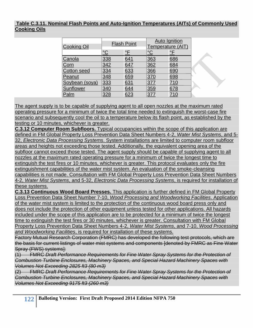
122 Balloting Version: First Draft Proposed 2014 Edition NFPA 750
Table C.3.11. Nominal Flash Points and Auto-Ignition Temperatures (AITs) of Commonly Used Cooking Oils
Cooking Oil Flash Point
Auto Ignition Temperature (AIT)
°C °F °C °F
Canola 338 641 363 686
Corn 342 647 362 684
Cotton seed 334 633 366 690
Peanut 348 659 370 698
Soybean (soya) 333 631 377 710
Sunflower 340 644 359 678
Palm 328 623 377 710
The agent supply is to be capable of supplying agent to all open nozzles at the maximum rated operating pressure for a minimum of twice the total time needed to extinguish the worst-case fire scenario and subsequently cool the oil to a temperature below its flash point, as established by the testing or 10 minutes, whichever is greater. C.3.12 Computer Room Subfloors. Typical occupancies within the scope of this application are defined in FM Global Property Loss Prevention Data Sheet Numbers 4-2, Water Mist Systems, and 5-32, Electronic Data Processing Systems. System installations are limited to computer room subfloor areas and heights not exceeding those tested. Additionally, the equivalent opening area of the subfloor cannot exceed those tested. The agent supply should be capable of supplying agent to all nozzles at the maximum rated operating pressure for a minimum of twice the longest time to extinguish the test fires or 10 minutes, whichever is greater. This protocol evaluates only the fire extinguishment capabilities of the water mist system. An evaluation of the smoke-cleansing capabilities is not made. Consultation with FM Global Property Loss Prevention Data Sheet Numbers 4-2, Water Mist Systems, and 5-32, Electronic Data Processing Systems, is required for installation of these systems. C.3.13 Continuous Wood Board Presses. This application is further defined in FM Global Property Loss Prevention Data Sheet Number 7-10, Wood Processing and Woodworking Facilities. Application of the water mist system is limited to the protection of the continuous wood board press only and does not include the protection of other equipment unless tested for other applications. All hazards included under the scope of this application are to be protected for a minimum of twice the longest time to extinguish the test fires or 30 minutes, whichever is greater. Consultation with FM Global Property Loss Prevention Data Sheet Numbers 4-2, Water Mist Systems, and 7-10, Wood Processing and Woodworking Facilities, is required for installation of these systems. Factory Mutual Research Corporation (FMRC) has developed the following test protocols, which are the basis for current listings of water mist systems and components [denoted by FMRC as Fine Water Spray (FWS) systems]: (1) FMRC Draft Performance Requirements for Fine Water Spray Systems for the Protection of Combustion Turbine Enclosures, Machinery Spaces, and Special Hazard Machinery Spaces with Volumes Not Exceeding 2825 ft3 (80 m3) (2) FMRC Draft Performance Requirements for Fine Water Spray Systems for the Protection of Combustion Turbine Enclosures, Machinery Spaces, and Special Hazard Machinery Spaces with Volumes Not Exceeding 9175 ft3 (260 m3)

123 Balloting Version: First Draft Proposed 2014 Edition NFPA 750
(3) FMRC Draft Performance Requirements for Fine Water Spray Systems for the Protection of Combustion Turbine Enclosures, Machinery Spaces, and Special Hazard Machinery Spaces with Volumes Exceeding 9175 ft3 (260 m3) (4) FMRC Draft Performance Requirements for Fine Water Spray Systems for the Protection of Light Hazard Occupancies (5) FMRC Draft Performance Requirements for Fine Water Spray Systems for the Protection of Wet Benches and Other Processing Equipment (6) FMRC Draft Performance Requirements for Water Mist Systems for Local Application System Protection C.3.1.1 Note that the term machinery space refers to flammable liquid hazards no greater than those of diesel fuel, and the term special hazard machinery space refers to flammable liquid hazards no greater than those of n-heptane. These terms should not be confused with the term machinery space used in the International Maritime Organization (IMO) documents relating to fine water spray. They are not intended to be interchangeable. C.3.1.2 The standards describe fire test performance criteria and methods. Because each fine water spray system is unique in its design and use of components, the component testing of each fine water spray system is evaluated on a case-by-case basis. The components are tested for functionality, performance, integrity, and reliability. The manufacturers’ design, installation, and maintenance manual(s) are reviewed for technical content and clarity. The supplied hydraulic calculations are also reviewed. C.3.2 FMRC Draft Performance Requirements for Fine Water Spray Systems for the Protection of Combustion Turbine Enclosures, Machinery Spaces, and Special Hazard Machinery Spaces with Volumes Not Exceeding 2825 ft3 (80 m3). C.3.2.1 The objective of this standard is to ensure that the fine water spray system extinguishes spray and pool fires that can occur, for example, due to breaks in lubrication, hydraulic, or fuel lines. Typically, these fires are highly shielded. While spray fires can occur only as the result of a supply line break, pool fires can occur as a result of a breakage or as a result of a small leak over a large period of time. This standard is limited to volumes not exceeding 80 m3 (2825 ft3). The FMRC standard assumes automatic interlocks for the following: (1) All fuel supply lines (for combustion turbines, bearing lubrication can be left on to allow the turbine to coast down) (2) Door closures (3) Ventilation shutdown (4) Electrical systems C.3.2.2 The water supply required is dependent on the application. For combustion turbines, the water supply has to be sufficient to protect the turbine for the duration of its coast downtime. For machinery spaces and special hazard machinery spaces, the protection time is 10 minutes. C.3.2.3 The detection is by means of heat detectors. The detection is so designed as to detect the fire and activate the fine water spray system within 60 seconds of the ignition. C.3.2.4 The fine water spray system has to extinguish all spray and pool fires within 5 minutes from the time of ignition. Tests are conducted in closed enclosures as well as enclosures with natural ventilation. For optional protection of insulated combustion turbines, the insulation mat can be suppressed rather than extinguished. C.3.2.5 In addition to the fire performance criteria, fine water spray systems used for the protection of combustion turbines cannot cause damage to the turbine by means of thermal shock or cracking of the turbine casing or induce blade rubbing. The rate of cooling of the steel test plate (1m×2m×5cmthick) must not exceed limits set by FMRC. It can be more difficult to successfully pass

124 Balloting Version: First Draft Proposed 2014 Edition NFPA 750
the cooling test than to pass the fire tests, and the results of the cooling test often indicate the number, type, and placement of the fine water spray nozzles. C.3.3 FMRC Draft Performance Requirements for Fine Water Spray Systems for the Protection of Combustion Turbine Enclosures, Machinery Spaces, and Special Hazard Machinery Spaces with Volumes Not Exceeding 9175 ft3 (260 m3). C.3.3.1 The objective of this standard is to ensure that the fine water spray system extinguishes spray and pool fires that can occur, for example, due to breaks in lubrication, hydraulic, or fuel lines. Typically, these fires are highly shielded. While spray fires can occur only as the result of a supply line break, pool fires can occur as a result of a breakage or as a result of a small leak over a large period of time. This standard is limited to volumes not exceeding 260 m3 (9175 ft3). The FMRC standard assumes automatic interlocks for the following: (1) All fuel supply lines (for combustion turbine, bearing lubrication can be left on to allow the turbine to coast down) (2) Door closures (3) Ventilation shutdown (4) Electrical systems C.3.3.2 The water supply required is dependent on the application. For combustion turbines, the water supply has to be sufficient to protect the turbine for the duration of its coast downtime. For machinery spaces and special hazard machinery spaces, the protection time is 10 minutes. C.3.3.3 The detection is by means of heat detectors. The detection is so designed as to detect the fire and activate the fine water spray system within 60 seconds of the ignition. C.3.3.4 The fine water spray system has to extinguish all spray and pool fires within 5 minutes from the time of ignition. Tests are conducted in closed enclosures as well as enclosures with natural ventilation. For optional protection of insulated combustion turbines, the insulation can be suppressed rather than extinguished. In addition to demonstrating performance in volumes not exceeding 260 m3 (9175 ft3), systems also have to demonstrate the capability to perform in small [130 m3 (4590 ft3)] enclosures. C.3.3.5 In addition to the fire performance criteria, fine water spray systems used for the protection of combustion turbines cannot cause damage to the turbine by means of thermal shock, cause cracking of the turbine casing, or induce blade rubbing. The rate of cooling of the steel test plate (1m×2m×5cm thick) cannot exceed limits set by FMRC. It can be more difficult to successfully pass the cooling test than to pass the fire tests, and the results of the cooling test often indicate the number, type, and placement of the fine water spray nozzles. C.3.4 FMRC Draft Performance Requirements for Fine Water Spray Systems for the Protection of Combustion Turbine Enclosures, Machinery Spaces, and Special Hazard Machinery Spaces with Volumes Exceeding 9175 ft3 (260 m3). C.3.4.1 The objective of this standard is to ensure that the fine water spray system extinguishes spray and pool fires that can occur, for example, due to breaks in lubrication, hydraulic, or fuel lines. Typically, these fires are highly shielded. Although spray fires can occur only as the result of a supply line break, pool fires can occur as a result of a breakage or as a result of a small leak over a large period of time. The FMRC standard assumes automatic interlocks for the following: (1) All fuel supply lines (for combustion turbines, bearing lubrication can be left on to allow the turbine to coast down) (2) Door closures (3) Ventilation shutdown (4) Electrical systems

125 Balloting Version: First Draft Proposed 2014 Edition NFPA 750
C.3.4.2 This standard is based on the IMO Standard for Shipboard Machinery Spaces, although the hazards discussed in both documents are different. Due to differences in system design and performance, extrapolation of results to larger room sizes is not permitted by FMRC at this time. C.3.4.3 The water supply required is dependent on the application. For combustion turbines, the water supply has to be sufficient to protect the turbine for the duration of its coast downtime. For machinery spaces and special hazard machinery spaces, the protection time is 60 minutes. Typically, the volumes tested exceed 800 m3 (28,230 ft3). C.3.4.4 The detection is by means of heat detectors. The detection is so designed as to detect the fire and activate the fine water spray system within 60 seconds of the ignition. C.3.4.5 The fine water spray system has to extinguish all spray, pool, and crib fires within 30 minutes from the time of ignition. The exception is a small shielded diesel pool fire that has to be suppressed. Tests are conducted in enclosures with natural ventilation. For optional protection of insulated combustion turbines, the insulation mat can be suppressed rather than extinguished. C.3.4.6 In addition to the fire performance criteria, fine water spray systems used for the protection of combustion turbines cannot cause damage to the turbine by means of thermal shock or cracking of the turbine casing or induce blade rubbing. The rate of cooling of the steel test plate (1 m × 2 m × 5 cm thick) cannot exceed limits set by FMRC. It can be more difficult to successfully pass the cooling test than to pass the fire tests, and the results of the cooling test often indicate the number, type, and placement of the fine water spray nozzles. C.3.5 FMRC Draft Performance Requirements for Fine Water Spray Systems for the Protection of Light Hazard Occupancies. C.3.5.1 The objective of this standard is to ensure that the fine water spray system controls fires typically found in light hazard occupancies and prevents the spread of the fire beyond the room or area of origin. These fires typically involve furnishings and wall coverings. This standard limits the heights of enclosed spaces to 2.4 m (8 ft) and the heights of unrestricted spaces to 5 m (16 ft 5 in.). C.3.5.2 This standard is based on the IMO Standard for Shipboard Corridors, Cabins, and Public Spaces, although the hazards discussed in both documents are different. C.3.5.3 The water supply required is 60 minutes for the most remote nine nozzles at the rated operating pressure. C.3.5.4 The detection is by means of individual heat responsive elements on the nozzles. The nozzles should meet FMRC requirements for quick response sprinklers and are limited to a maximum nominal temperature rating of 107°C (225°F). Nozzle spacing is to be uniform with uniform spacing, preferably one-half of the standard nozzle spacing, from the wall. C.3.5.5 The fire performance tests consist of three test areas: small compartment, large compartment, and open space. C.3.5.5.1 The small compartment [3 m × 4 m × 2.4 m (10 ft × 13 ft × 8 ft) high] has a door 0.8 m × 2.2 m (2 ft 6 in. × 7 ft 2 in.) high and represents a small ship cabin. The fuel package for this room consists of two bunk beds identical to the IMO specification. The purpose of this test is to delineate mist nozzles from sprinklers. The fire is ignited on the lower mattress, and the test methodology is identical to that specified in the IMO test series. Pass/fail criteria are based on damage of the lower bunk (maximum of 40 percent), ceiling surface temperature over ignition [maximum of 260°C (500°F)], and a maximum gas temperature 76 mm (3 in.) below the ceiling of 315°C (600°F). C.3.5.5.2 The large compartment [having equal sides not exceeding 6 m (20 ft) and a height of 2.4 m (8 ft)] has two doors [each 0.8 m × 2.2 m (2 ft 6 in. × 7 ft 2 in.) high] located in diagonally opposite corners. A nozzle is placed in the doorway opposite the fuel package. The fuel package and test method are identical to the IMO specification. The heptane under the wood crib is ignited first, then followed 40 seconds later by the ignition of the excelsior. The doorway nozzles do not operate
126 Balloting Version: First Draft Proposed 2014 Edition NFPA 750
(indicating that the fire would not have spread to an adjacent area). Additional pass/fail criteria include ceiling surface temperature over ignition [maximum of 265°C (510°F)] and a maximum gas temperature 76 mm (3 in.) below the ceiling of 315°C (600°F). C.3.5.5.3 The open space test is conducted under a ceiling with a minimum area of 80m2 (860 ft2) to simulate an uninterrupted area and a ceiling height of 5 m (16 ft 5 in.). At least 16 nozzles are installed in the ceiling and the fuel package (sofas, as outlined in the IMO specification) are to be arranged per the IMO specification. The test is conducted three times: once each with the ignition under one nozzle, between two nozzles, and between four nozzles. Pass/fail criteria are based on fewer than five nozzles operating, at least one unoperated nozzle beyond those that operate, damage of the sofa cushions (maximum of 50 percent), ceiling surface temperature over ignition [maximum of 260°C (500°F)], and a maximum gas temperature 76mm(3 in.) below the ceiling of 315°C (600°F). C.3.6 FMRC Draft Performance Requirements for Fine Water Spray Systems for the Protection of Wet Benches and Other Processing Equipment. C.3.6.1 The objective is to ensure that the fine water spray system extinguishes pool fires typically found in wet benches and other similar clean room processing equipment. C.3.6.2 The detection system has to be approved specifically for use in wet bench applications. Fine water spray systems used for this application are typically of the zoned, deluge type. Operating elements currently used in automatic sprinklers have not been shown to be sufficiently fast enough to prevent significant nonthermal damage. C.3.6.3 The simulated clean room is 5.5m× 3.7m× 3.7m(18 ft × 12 ft × 12 ft) high with porous ceiling and floor plates. An airflow (downward) with a velocity of 0.31 m/sec (60 ft/min) is maintained throughout the test. The minimum airflow by the open face of the wet bench is 4.5 m3/min/linear m (150 ft3/ min/linear ft). The wet bench measures approximately 2.3 m × 1.4m×2m(7.5 ft × 4.5 ft × 6.5 ft) high and is divided into two areas: the ventilated subsurface (or plenum) area and the working surface area. The subsurface dimensions are 0.8 m × 2.3 m × 0.6 m (2.6 ft × 7.5 ft × 2 ft) high. The working surface area is 0.8 m × 2.3 m (2.6 ft × 7.5 ft). C.3.6.4 All fires have to be extinguished in less than 60 seconds. C.3.6.5 Various fire scenarios are conducted to test the fine water spray system for the ventilated subsurface area. These include five pool fires (various sizes) utilizing polypropylene beads and solid coupons for fuel and at least one pool fire for each of the following flammable liquids: acetone, isopropyl alcohol (IPA), and n-heptane. The pan sizes and fire locations for the flammable liquid pool fire are at the discretion of FMRC based on observations of the fine water spray system. Obstructions are placed within the subsurface area such that approximately 50 percent of the nozzle discharge is blocked. C.3.6.6 Two tests are conducted to determine the effectiveness of a single nozzle in an unventilated space utilizing the subsurface area as a test chamber. The first test utilizes a polypropylene pool fire, and the second test uses a flammable liquid pool fire. Pan size and flammable liquid are at the discretion of FMRC based on the outcome of the ventilated subsurface tests. Suitable barriers are placed in the test area to prevent direct impingement on the fire and to provide 50 percent blockage of the discharge. C.3.6.7 Several fire scenarios are conducted to test the fine water spray system for the working surface area. These include five pool fires (various sizes) utilizing polypropylene beads and solid coupons for fuel and at least one pool fire for each of the following flammable liquids: acetone, isopropyl alcohol (IPA), and n-heptane. The pan sizes and fire locations for the flammable liquid pool fire are at the discretion of FMRC based on observations made of the fine water spray system. The flammable liquid fires are also tested at the minimum and maximum nozzle heights, as specified by

127 Balloting Version: First Draft Proposed 2014 Edition NFPA 750
the manufacturer. A splashing test is conducted in which a single nozzle, located at the minimum vertical height above a pan of liquid containing dye, is discharged at the maximum pressure. None of the contents of the liquid pool are splashed outside a 0.4 m (16 in.) diameter circle centered on the pool. C.3.7 FMRC Draft Fire Test Protocol for Water Mist Systems for Local Application Protection. C.3.7.1 The objective of this standard is to ensure that the water mist system will extinguish combustible liquid spray and pool fires. These fires can occur on printing press stands, dip tanks, quench tanks, or lube oil–conditioning systems. The standard assumes the following: (1) Room ventilation is normal. (2) Obstructions over the protected area do not exceed that tested. (3) Fluid is contained within the diked area. C.3.7.2 The time required to extinguish the fire scenarios will be reported. The water supply required depends on the occupancy and the authority having jurisdiction. C.3.7.3 The system is to be automatically activated by a listed heat or flame detection system. C.3.7.4 The water mist system must extinguish the following fires at the maximum and minimum nozzle elevations and spacing. Maximum and minimum heights apply as follows: (1) For square pool fires, maximum height only for 1 m × 1 m and2m×2mpools; maximum and minimum heights for the 3 m × 3 m pool (2) For channel fires, maximum height only for Y and 2Y lengths; maximum and minimum heights for 3Y length (3) For heptane spray fires, maximum and minimum heights (4) For combined pool and spray fires, maximum height only (5) For offset pool fire, obstructed pool fire, and spray fire with
external ignition source, maximum and minimum heights C.3.7.4.1 Pool Fires. Pool fires are to be in square shapes from 1m2, 4 m2, and9m2 (10.8 ft2, 43.6 ft2, and 96 ft2) in area. C.3.7.4.2 Obstructed Pool Fires. The obstruction must be at least equivalent to a 0.6 m (2 ft) diameter drum located 0.5 m (1.6 ft) over the center of the pool. C.3.7.4.3 Channel Fires. Channel fires are to be at the width of the channel and at lengths of one, two, and three times the width. C.3.7.4.4 Spray Fires. Six MW heptane spray fires are conducted with the spray fire axis in the horizontal and vertical directions. C.3.7.4.5 Spray and Pool Fires. Horizontal spray fire tests are conducted with a 6 MW diesel spray fire at two different elevations and two different locations above the surface ofa2m×2m diesel pool fire. A 45 degree spray fire is conducted with a 6 MW diesel spray fire at two locations at one elevation above a 2 m × 2 m diesel pool fire. C.3.7.4.6 Diesel Soaked Paper Dust Fire. A fire involving a quantity of diesel fuel soaked into paper dust. C.3.7.5 The tests are conducted in enclosures large enough so that oxygen concentrations do not decrease below 20 percent.
C.4 Underwriters Laboratories Inc., Northbrook, IL, Fire Test Protocols. C.4.1 General. ANSI/UL 2167, Standard for Water Mist Nozzles for Fire Protection Service, contains a series of fire test protocols for evaluating water mist nozzles for listing purposes for the following types of hazards: (1) Shipboard machinery spaces (2) Shipboard passenger cabins
128 Balloting Version: First Draft Proposed 2014 Edition NFPA 750
(3) Shipboard passenger cabins >12 m2 (4) Shipboard public spaces (5) Residential areas (6) Light Hazard areas (7) Ordinary Hazard Group 1 (8) Ordinary Hazard Group 2 (9) Nozzle construction, design, and performance (10) Water mist nozzle markings (11) Design and installation manual (12) Manufacturing and production tests C.4.2 The UL 2167 Shipboard Test Protocols closely resemble the IMO test protocols, with some modifications in the number of tests and final acceptance criteria.
First Revision No. #:NFPA 750-2010 [FR 29: FileMaker]
C.4.3 Residential Areas. The ANSI/UL 2167 Test Protocol for Residential Areas is very similar to that for residential sprinklers. A residential fuel package is used in a compartment fitted with combustible wall panels and ceiling tiles. Six Three nozzles are installed in the room, which has two open doors on opposite sides, with the fuel package located in a corner. Two nozzles are located at their maximum spacing and the third nozzle is located near one of the door openings. Testing is required with a 2.4 m high ceiling and the maximum ceiling height specified in the manufacturer’s design and installation manual. Performance criteria include maximum temperatures at several locations and one nozzle is permitted to operate during the test. The nozzle closest to the fuel package is installed at its maximum spacing, and the remaining five nozzles are installed using their minimum permitted spacing. Performance criteria include maximum temperatures at several locations. If only one nozzles operates, the manufacturer’s design and installation manual has to specify at least a two nozzle design. If two or three nozzles operate, at least a four nozzle design is to be specified. C.4.4 Light Hazard Areas. The ANSI/UL 2167 Test Protocol for Light Hazard Areas, in addition to complying with the shipboard public space light hazard fire tests, requires a series of fire tests to measure the ability of the nozzles to limit fire growth in wood cribs.
First Revision No. #:NFPA 750-2010 [FR 39: FileMaker]
C.4.5 Ordinary Hazard Group 1. The ANSI/UL 2167 Test Protocol for Ordinary Hazard Group 1 Hazard Areas requires that fire tests be conducted both under an open ceiling and in a corner arrangement. The first series of fire tests is conducted under a smooth flat ceiling having provisions for venting gases around the perimeter set at the maximum height specified in the manufacturer’s design and installation manual. The fire source consists of a 4.7 m wide × 5.9 m long × 2.1 2.4 m high array of Class II commodity (double tri-wall corrugated paper cartons with a five-sided steel liner on a 107 cm × 107 cm × 12.7 cm high hardwood pallet). During the 45-minute test, ceiling steel temperatures cannot exceed 282 540°C (540 1000°F) for more than 5 minutes, the number of operating nozzles cannot exceed a design area of 93 m2, and damage to the commodity cannot exceed 50 percent. The corner fire tests are similar to the IMO public space corner tests except that empty cardboard cartons are used in lieu of the sofas. C.4.6 Ordinary Hazard Group 2. The ANSI/UL 2167 Test Protocol for Ordinary Hazard Group 2 Hazard Areas is similar to the Ordinary Hazard Group 1 fire tests except that the Group A plastic commodity and test array described in the IMO public space shopping and storage area fire tests is used as the open area test commodity.

129 Balloting Version: First Draft Proposed 2014 Edition NFPA 750
C.4.7 Nozzle Design, Construction, and Performance Requirements. These requirements are very similar to those specified by IMO. They also include requirements for open nozzles that are not specifically addressed by IMO. C.4.8 Nozzle Marking Requirements. ANSI/UL 2167 contains requirements for the marking of water mist nozzles. In the field, these markings provide a method of verifying that the proper nozzles have been installed. C.4.9 Design and Installation Manual. ANSI/UL 2167 requires the nozzle manufacturer to prepare a design and installation manual containing detailed information concerning the intended use and limitations associated with nozzles. C.4.10 Manufacturing and Production Tests. ANSI/UL 2167 requires the manufacturer to provide an acceptable production control, inspection, and test program. All automatic nozzles are subjected to a production leakage test at twice rated pressure but not less than 3.45 MPa. In addition, as part of a follow-up service program, samples are randomly selected on a periodic basis for follow-up inspections and tests.
C.5 Verband der Schadenversichen eV (VDS, Germany). C.5.1 General. VDS 2498, Guidelines for Water Extinguishing Systems Requirements and Test Methods for Fine Spray Nozzles, contains several fire test protocols. One protocol that has been recognized in Europe is Fine Spray Nozzles for Cable Conduit Tunnels. C.5.2 Fine Spray Nozzles for Cable Conduit Tunnels. This test incorporates a propane burner flame as the ignition source at one end of an array of plastic sheathed cables.
C.6 Bridging the Gap Between Test Protocols and Actual Installations. C.6.1 One of the greatest challenges to engineering of water mist fire suppression systems lies in determining whether the conditions of a particular test protocol are representative of the actual conditions in a given application. An engineering analysis should be applied to evaluate the scale and significance of variations, based on an understanding of the dynamics of the interaction of water mist with fire. At least the following application parameters should be considered: (1) Is the fuel similar to the test protocol (liquid or solid fuel, flash point, combustibility, quantity,
arrangement)? (2) Is the compartment volume equal to or less than the volume of the test room? (3) Is the compartment height equal to or less than the test protocol? (4) Is the compartment ventilation condition similar (area of openings, position of openings)? (5) Are there more obstructions to the distribution of mist than the test protocol? (6) Is the duration of protection provided by the listed system appropriate for the actual level of
protection desired? C.6.2 Extrapolation. It is recommended that questions about the match between test conditions on which the listing is based and the conditions of the actual installation be addressed through consultation with the listing agency, the authority having jurisdiction, or other agencies with demonstrated qualifications in the field.
Annex D Reliability This annex is not a part of the requirements of this NFPA document but is included for informational purposes only.
D.1 General. Two methods are used to determine reliability: operating experience and predictive techniques. D.1.1 Operating Experience. The Technical Committee on Water Mist Fire Suppression Systems contacted the U.S. Department of Energy, the U.S. Department of Defense, the National Aeronautics and Space Administration, the Coast Guard, passenger cruise ship companies, and other organizations known to have installed water mist systems. The purpose was to determine the number
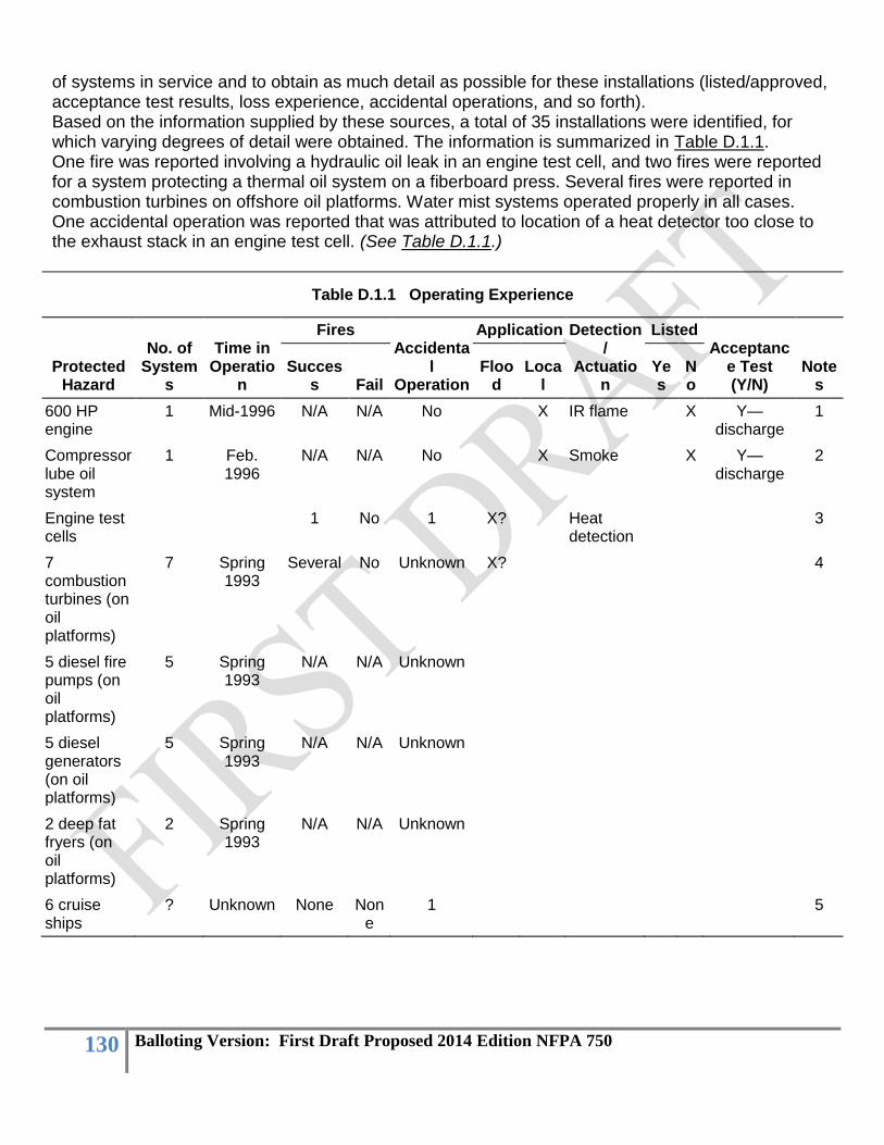
130 Balloting Version: First Draft Proposed 2014 Edition NFPA 750
of systems in service and to obtain as much detail as possible for these installations (listed/approved, acceptance test results, loss experience, accidental operations, and so forth). Based on the information supplied by these sources, a total of 35 installations were identified, for which varying degrees of detail were obtained. The information is summarized in Table D.1.1. One fire was reported involving a hydraulic oil leak in an engine test cell, and two fires were reported for a system protecting a thermal oil system on a fiberboard press. Several fires were reported in combustion turbines on offshore oil platforms. Water mist systems operated properly in all cases. One accidental operation was reported that was attributed to location of a heat detector too close to the exhaust stack in an engine test cell. (See Table D.1.1.)
Table D.1.1 Operating Experience
Protected Hazard
No. of System
s
Time in Operatio
n
Fires Accidenta
l Operation
Application Detection/
Actuation
Listed Acceptanc
e Test (Y/N)
Notes
Success Fail
Flood
Local
Yes
No
600 HP engine
1 Mid-1996 N/A N/A No X IR flame X Y—discharge
1
Compressor lube oil system
1 Feb. 1996
N/A N/A No X Smoke X Y—discharge
2
Engine test cells
1 No 1 X? Heat detection
3
7 combustion turbines (on oil platforms)
7 Spring 1993
Several No Unknown X? 4
5 diesel fire pumps (on oil platforms)
5 Spring 1993
N/A N/A Unknown
5 diesel generators (on oil platforms)
5 Spring 1993
N/A N/A Unknown
2 deep fat fryers (on oil platforms)
2 Spring 1993
N/A N/A Unknown
6 cruise ships
? Unknown None None
1 5

131 Balloting Version: First Draft Proposed 2014 Edition NFPA 750
Lube oil systems for 6 combustion turbine driven compressors (natural gas pipeline)
6 1996 (2) 1997(2) 1998(2)
None None
None Combination
Thermal oil system on fiberboard press
1 2 None
None X? X 6
Notes: 1. At some time after acceptance test, white residue was noted in pipe. Laboratory tests determined it to be zinc oxide. Piping was flushed but residue remained. 2. During acceptance test, system failed to operate due to low pressure. Investigation determined that a ¼ in. copper tube had separated from a brass fitting. On second discharge test, 3 of 25 nozzles were plugged, possibly due to use of pipe joint compound. System remained out of service 22 months after installation due to concern for accidental operation during cutting and welding operations. Chalk-like material had formed on interior surface of pipe; believed to be oxide. 3. Fire activation: A hydraulic line break occurred on an engine under test. System operated properly and extinguished the fire. Accidental activation: System operated 50 hours into engine test, near end of test cycle. One heat detector may have been located too close to exhaust stack. 4. Systems are tested periodically with limited discharge of a few seconds to verify the system is operational. 5. Six vessels have water mist protection for engine rooms, dining areas, ballrooms, and escape routes. Engine room systems are manually controlled. One accidental operation, in dining room. 6. Oil spray fire burned 2–3 hours, fought unsuccessfully by plant personnel using hose streams. Water mist system was manually activated and extinguished fire within 20 seconds. When press was placed back in service, a second fire developed at an undetected crack in thermal oil system piping. This fire was also extinguished by the water mist system. D.1.2 Predictive Techniques. Predictive techniques outlined in ISA-S84.01, Application of Safety Instrumentation to the Process Industries, provide guidance to determine the safety integrity level (SIL) of a protection system. The main document establishes SILs needed for various safety systems (SIS). Parts 2, 3, and 4 of ISA-S84.01 provide information on three different methods for determining reliability: simplified equations, fault tree analysis, and Markov analysis. Part 5 of ISA-S84.01 determines the probability of failure on demand (PFD) of Logic Solvers via Markov analysis. The average probability of failure of a system at various SILs is shown in Table D.1.2.
Table D.1.2 Safety Integrity Levels
SIL PFD (average)
1 10−1 to 10−2
2 10−2 to 10−3
132 Balloting Version: First Draft Proposed 2014 Edition NFPA 750
3 10−3 to 10−4
The user of the system should designate the safety level desired based on either dollar loss or personnel injury. Where a high level of safety is required, the analysis should be done by an independent third party. For lower safety levels, the manufacturer could do the analysis. The U.S. Navy used reliability studies to evaluate the reliability of halon systems for shipboard use. Approval for service was dependent on a reliability study. The main advantage to the analysis was the identification of single points of failure. Failure rates were determined for the systems designed, but these appeared to be less meaningful than identifying single points of failure. Reliability was improved by eliminating abort valves and installing a manual actuation system to bypass the time delay for the predischarge alarm. Manual activation was acceptable because the protected areas onboard ship are constantly occupied. D.1.3 Conclusions. The following conclusions were derived from the review of operating experience: (1) Systems are being installed to protect applications for which they have not been tested. (2) Users do not have adequate information to determine whether the system has been properly
designed and installed. The following additional information is needed: (a) List of system components (b) Design, installation, and maintenance manual (c) Logic diagram
(3) Acceptance tests are critical to the reliability of the system. Full-flow tests are the best indication that a system has been properly installed. For installations where full-flow tests cannot be done, water should be flowed as close to the nozzles as possible, then diverted to a safe area. The rest of the system should be visually inspected, or gas should flow through the system to be sure it is clear.
(4) Operating experience is more accurate than predictive techniques in determining the reliability of a system. There is not enough operating experience to date for water mist systems. A questionnaire like the one shown in Figure D.1.3, distributed to users of water mist systems and returned to the Committee, would be helpful in gathering information.
(5) Where a water mist system is used for life safety, a predictive method should be used to justify that the system is as reliable as the protection system required by code.

133 Balloting Version: First Draft Proposed 2014 Edition NFPA 750
FIGURE D.1.3 Water Mist System Questionnaire Form to Determine Reliability of Water Mist
Systems. Annex E Informational References
E.1 Referenced Publications. The documents or portions thereof listed in this annex are referenced within the informational sections of this standard and are not part of the requirements of this document unless also listed in Chapter 2 for other reasons.
First Revision No. 79:NFPA 750-2010 [FR 66: FileMaker]
E.1.1 NFPA Publications. National Fire Protection Association, 1 Batterymarch Park, Quincy, MA 02169-7471 NFPA 3, Recommended Practice for Commissioning and Integrated Testing of Fire Protection and Life Safety Systems, 2012 edition. NFPA 13, Standard for the Installation of Sprinkler Systems, 2010 edition. NFPA 15, Standard for Water Spray Fixed Systems for Fire Protection, 2007 edition. NFPA 20, Standard for the Installation of Stationary Pumps for Fire Protection, 2010 edition. NFPA 25, Standard for the Inspection, Testing, and Maintenance of Water-Based Fire Protection Systems, 2008 edition. NFPA 70®, National Electrical Code®, 2008 edition. NFPA 72®, National Fire Alarm and Signaling Code, 2010 edition. NFPA 502, Standard for Road Tunnels, Bridges, and Other Limited Access Highways, 2011 edition.

134 Balloting Version: First Draft Proposed 2014 Edition NFPA 750
Cote, A. E., and J. L. Linville, eds. “Water Mist Suppression Systems,” in Fire Protection Handbook, 18th edition. E.1.2 Other Publications. E.1.2.1 ANSI Publications. American National Standards Institute, Inc., 25 West 43rd Street, 4th floor, New York, NY 10036. ANSI C2, National Electrical Safety Code, 1993. E.1.2.2 ASME Publications. American Society of Mechanical Engineers, Three Park Avenue, New York, NY 10016. ANSI/ASME B31.1, Power Piping Code, 1998. E.1.2.3 ASTM Publications. ASTM International, 100 Barr Harbor Drive, P. O. Box C700, West Conshohocken, PA 19428-2959. ASTM E 380, Standard Practice for Use of the International System of Units (SI) (the Modernized Metric System), 1993. ASTM E 799, Standard Practice for Determining Data Criteria and Processing for Liquid Drop Size Analysis, 1992. ASTM F 1547, Standard Guide Listing Relevant Standards and Publications for Commercial Shipbuilding, 1994. E.1.2.4 CSA Publications. Canadian Standards Association, 5060 Spectrum Way, Mississauga, Ontario, L4W 5N6, Canada. CAN3-A234.1, Canadian Metric Practice Guide, 1979.
First Revision No. 107:NFPA 750-2010 [FR 76: FileMaker]
E.1.2.5 FM Approvals Publications. FM Approvals, 1151 Boston-Providence Turnpike, P.O. Box 9102, Norwood, MA, 02062. ANSI/FM Approvals 5560, American National Standard for Water Mist Systems, December 2007. FM Approvals 5560, Approval Standard for Water Mist Systems, March 2009. E.1.2.56 FMGR Publications. FM Global Research, FM Global, 1301 Atwood Avenue, P.O. Box 7500, Johnston, RI 02919. FMRC Draft Performance Requirements for Fine Water Spray Systems for the Protection of Combustion Turbine Enclosures, Machinery Spaces, and Special Hazard Machinery Spaces with
Volumes Not Exceeding 2825 ft3 (80 m3). FMRC Draft Performance Requirements for Fine Water Spray Systems for the Protection of Combustion Turbine Enclosures, Machinery Spaces, and Special Hazard Machinery Spaces with
Volumes Not Exceeding 9175 ft3 (260 m3). FMRC Draft Performance Requirements for Fine Water Spray Systems for the Protection of Combustion Turbine Enclosures, Machinery Spaces, and Special Hazard Machinery Spaces with
Volumes Exceeding 9175 ft3 (260 m3). FMRC Draft Performance Requirements for Fine Water Spray Systems for the Protection of Light Hazard Occupancies. FMRC Draft Performance Requirements for Fine Water Spray Systems for the Protection of Wet Benches and Other Processing Equipment. FMRC Draft Performance Requirements for Water Mist Systems for Local Application System Protection. E.1.2.67 FSSA Publications. Fire Suppression Systems Association, 5024-R Campbell Blvd., Baltimore, MD 21236-5974. Pipe Design Handbook for Use with Special Hazards Fire Suppression Systems.

135 Balloting Version: First Draft Proposed 2014 Edition NFPA 750
E.1.2.78 IMO Publications. International Maritime Organization, 4 Albert Embankment, London, SEI 7SR, United Kingdom. IMO Code for Application of Fire Test Procedures, 1998. IMO MSC/Circ. 668, Alternative Arrangements for Halon Fire-Extinguishing Systems in Machinery Spaces and Pump-Rooms. IMO MSC/Circ. 728, Amendments to the Test Method for Equivalent Water-Based Fire Extinguishing Systems for Machinery Spaces of Category A and Cargo Pump-Rooms Contained in MSC/Circ. 668. IMO MSC/Circ. 913, Guidelines for the Approval of Fixed Water-Based Local Application Fire-Fighting Systems for Use in Category A Machinery Spaces. IMO MSC/Circ 1165, Revised Guidelines for Approval of Equivalent Water-Based Fire Extinguishing Systems for Machinery Spaces and Cargo Pump Rooms. IMO Resolution A.800(19), Revised Guidelines for Approval of Sprinkler Systems. IMO Standard for Shipboard Corridors, Cabins, and Public Spaces. IMO Standard for Shipboard Machinery Spaces. SOLAS Resolution 10, Fixed Pressure Water Spray Systems. E.1.2.89 ISA Publications. Instrumentation, Systems, and Automation Society, 67 Alexander Drive, P.O. Box 12277, Research Triangle Park, NC 27709. ISA-S84.01, Application of Safety Instrumentation to the Process Industries, 1996.
First Revision No. 50:NFPA 750-2010 [FR 65: FileMaker]
E.1.2.910 UL Publications. Underwriters Laboratories Inc., 333 Pfingsten Road, Northbrook, IL 60062-2096. ANSI/UL 2167, Standard for Water Mist Nozzles for Fire Protection Service, 2011. 2002 with revisions through January 2009 E.1.2.1011 U.S. Coast Guard Publication. 2100 Second Street, S.W., Washington, DC 20593-0001. NVIC 9-97, Guide to Structural Fire Protection, 1997. E.1.2.1112 VDS Publication. VDS, Pasteurstrasse 17A, Koln 50735, Germany. VDS 2498, Guidelines for Water Extinguishing Systems Requirements and Test Methods for Fine Spray Nozzles, 1996 edition.
E.2 Informational References. (Reserved) E.3 References for Extracts in Informational Sections. (Reserved)