Đstanbul technical university institute of science...
TRANSCRIPT

ĐSTANBUL TECHNICAL UNIVERSITY ���� INSTITUTE OF SCIENCE AND TECHNOLOGY
M.Sc. Thesis by Gözde ERGÜL
Department : Electronics & Communication
Programme : Telecommunication Engineering
JUNE 2009
VIDEO MULTICASTING OVER 3G/UMTS NETWORKS


ĐSTANBUL TECHNICAL UNIVERSITY ���� INSTITUTE OF SCIENCE AND TECHNOLOGY
M.Sc. Thesis by Gözde ERGÜL, B.Sc.
(504061318)
Date of submission : 04 May 2009
Date of defence examination: 04 June 2009
Supervisor (Chairman) : Assoc. Prof. Dr. Selçuk PAKER (ĐTÜ) Members of the Examining Committee : Dr. H. Bülent YAĞCI (ĐTÜ)
Asst. Prof. Dr. Berk ÜSTÜNDAĞ (ĐTÜ)
JUNE 2009
VIDEO MULTICASTING OVER 3G/UMTS NETWORKS


HAZĐRAN 2009
ĐSTANBUL TEKNĐK ÜNĐVERSĐTESĐ ���� FEN BĐLĐMLERĐ ENSTĐTÜSÜ
YÜKSEK LĐSANS TEZĐ Gözde ERGÜL
(504061318)
Tezin Enstitüye Verildiği Tarih : 04 Mayıs 2009
Tezin Savunulduğu Tarih : 04 Haziran 2009
Tez Danışmanı : Doç. Dr. Selçuk PAKER (ĐTÜ) Diğer Jüri Üyeleri : Dr. H. Bülent YAĞCI (ĐTÜ)
Yrd. Doç. Dr. Berk ÜSTÜNDAĞ (ĐTÜ)
3G/UMTS ŞEBEKELERĐNDE VĐDEO ÇOĞULLAMA


v
FOREWORD
I would like to express my gratitude to my supervisor Doç. Dr. Selçuk Paker. He always supported and encouraged me during my studies. His support, guidance and tolerance throughout my study, made possible the completion of this thesis.
I am in debt to my parents for their infinite support and thrust during my whole life. Finally, I would like to express my deepest gratitude to my brother Umut ERGÜL, who has encouraged me to complete my master study.
May 2009
Gözde ERGÜL

vi

vii
TABLE OF CONTENTS
Page
ABBREVIATIONS............................................................................................... ix LIST OF TABLES................................................................................................ xi LIST OF FIGURES ............................................................................................. xii SUMMARY......................................................................................................... xiii 1. INTRODUCTION...............................................................................................1
1.1 Outline and Purpose of the Thesis ...................................................................2 2. MULTICAST FUNDAMENTALS....................................................................5
2.1 Basic Concepts of Multicast ............................................................................6 2.2 Drawbacks of Multicast...................................................................................7
3. OVERVIEW OF UMTS NETWORKS............................................................11 3.1 Introduction...................................................................................................11 3.2 UMTS Overview...........................................................................................11
3.2.1 UMTS Services .....................................................................................11 3.3 UMTS network architecture ..........................................................................12
4. MULTICAST FRAMEWORK FOR 3G/UMTS ..........................................15 4.1 MBMS Service Provision Phases...................................................................16 4.2 MBMS Architecture ......................................................................................18
4.2.1 UTRAN/GERAN ...................................................................................18 4.2.2 SGSN.....................................................................................................18 4.2.3 GGSN ....................................................................................................19 4.2.4 BM-SC...................................................................................................19
4.3 MBMS Channel Structure in the Radio Access Network (RAN)....................20 4.3.1 Macro diversity and combining technologies for MBMS ........................22
4.4 MBMS Services ............................................................................................24 4.5 MBMS Streaming Delivery Method ..............................................................26
5. MOBILE MULTIMEDIA AND STREAMING ..............................................29 5.1 MPEG4 Compression Format........................................................................30 5.2 H.263 Video Compression Format.................................................................30 5.3 H.264/AVC ...................................................................................................31 5.4 Performance Comparison of Video Codecs....................................................31 5.5 Streaming......................................................................................................32
5.5.1 Streaming application in 3G networks ....................................................33 5.6 File Formats for Mobile Multimedia..............................................................34
6. OVERVIEW OF TECHNOLOGIES FOR MOBILE TV...............................35 6.1 Requirements for Mobile TV Services...........................................................35 6.2 Alternative Mobile TV Technologies.............................................................36
6.2.1 IPDC and DVB ......................................................................................37 6.2.2 MediaFLO..............................................................................................39 6.2.3 Digital Multimedia Broadcasting (DMB)................................................41 6.2.4 Terrestrial Integrated Services Digital Broadcasting (ISDB-T) ...............42 6.2.5 Comparison of Mobile TV technologies .................................................43

viii
6.3 Spectrum for Mobile TV ............................................................................... 44 6.3.1 Spectrum for 3G/UMTS technologies .................................................... 46
6.4 Terminals for Mobile TV .............................................................................. 47 7. MOBILE TV TRIALS AND USER FEEDBACKS......................................... 49
7.1 DVB-H Trials ............................................................................................... 49 7.2 MBMS Trials................................................................................................ 51 7.3 T-DMB Trials ............................................................................................... 51 7.4 MediaFLO Trials .......................................................................................... 51 7.5 User Feedbacks............................................................................................. 52
8. CONCLUSION AND FUTURE WORK ......................................................... 57 REFERENCES..................................................................................................... 59 CURRICULUM VITAE ...................................................................................... 61
ix
ABBREVIATIONS
3GPP : Third Generation Partnership Project AVC : Advanced Video Coding BM-SC : Broadcast/Multicast Service Center CN : Core Network DAB : Digital Audio Broadcasting DCH : Dedicated Channel DMB : Digital Multimedia Broadcasting DVB-H : Digital Video Broadcasting Handheld DVB-T : Digital Video Broadcasting Terrestrial EDGE : Enhanced Data Rates for GSM Evolution EPG : Electronic Program Guide ESG : Electronic Service Guide ETSI : European Telecommunications Standards Institute FACH : Forward Access Channel FLO : Forward Link Only GERAN : GSM EDGE Radio Access Network GPRS : General Packet Radio Service GPS : Global Positioning System GTP : GPRS Tunnelling Protocol HS-DSCH : High Speed Downlink Shared Channel HSDPA : High-Speed Downlink Packet Access IETF : Internet Engineering Task Force ISDB-T : Integrated Services Digital Broadcasting Terrestrial ITU-R : International Telecommunications Union – Radio Communication ITU-T : International Telecommunications Union – Telecommunication Standards Sector JPEG : Joint Photographers Expert Group LOC : Local Operations Center MBMS : Multimedia Broadcast and Multicast Service MCCH : MBMS point-to-multipoint Control Channel MICH : MBMS Notification Indicator Channel MPEG : Moving Pictures Expert Group MSC : Mobile-services Switching Center MSCH : MBMS point-to-multipoint Scheduling Channel MTCH : MBMS point-to-multipoint Traffic Channel PSS : Packet switched Streaming Service QoS : Quality of Service RAN : Radio Access Network RNC : Radio Network Controller RTCP : Real-Time Transport Control Protocol RTP : Real-Time Transport Protocol RTSP : Real Time Streaming Protocol S-CCPCH : Secondary Common Control Physical Channel

x
SDP : Session Description Protocol UDP : User Datagram Protocol UHF : Ultra High Frequency UMTS : Universal Mobile Telecommunications System UTRAN : UMTS Radio Access Network VHF : Very High Frequency VoD : Video-on-Demand WCDMA : Wideband Code Division Multiple Access

xi
LIST OF TABLES
Page
Table 3.1: UMTS Tele-services and specific QoS values........................................12 Table 5.1: Sequence Related Information ...............................................................31 Table 5.2: H.263 and H.264 Video Codec Performance Comparison......................32 Table 7.1: DVB-H based trials (as April of 2009) [17] ...........................................49
xii
LIST OF FIGURES
Page
Figure 2.1: Point-to-Point Data Delivery Method ....................................................5 Figure 2.2 : Broadcast Data Delivery Method..........................................................6 Figure 3.1: UMTS Network Architecture............................................................... 13 Figure 4.1: Example of multicast mode network .................................................... 16 Figure 4.2: Phases of MBMS service provisioning in the multicast mode[6].......... 17 Figure 4.3: MBMS Architecture ............................................................................ 18 Figure 4.4: BM-SC functional structure................................................................. 19 Figure 4.5: Functional layers for MBMS User Service........................................... 25 Figure 4.6: Protocol stack view for MBMS streaming delivery method ................. 26 Figure 4.7: An Example of MBMS SDP................................................................ 27 Figure 5.1: Example of video based encoder/decoder system................................. 29 Figure 5.2: User Plane Protocol Stack for 3GPP-PSS............................................. 33 Figure 6.2: Protocol Stack of IP Datacast............................................................... 38 Figure 6.3 : Implementation of Interaction Channel ............................................... 39 Figure 6.4: FLO technology architecture ............................................................... 40 Figure 6.5: Use of spectrum for Mobile TV ........................................................... 45 Figure 6.6: European Frequency Allocations for UMTS ........................................ 46 Figure 7.1: Locations where users are watching Mobile TV.................................. 53 Figure 7.2: Usage percentage of categories wathced on Mobile TV ...................... 54 Figure 7.3: Comparison of mobile TV, radio and traditional TV............................ 55
xiii
VIDEO MULTICASTING OVER 3G/UMTS NETWORKS
SUMMARY
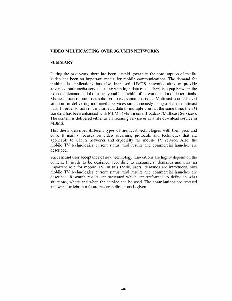
During the past years, there has been a rapid growth in the consumption of media. Video has been an important media for mobile communications. The demand for multimedia applications has also increased. UMTS networks aims to provide advanced multimedia services along with high data rates. There is a gap between the expected demand and the capacity and bandwidth of networks and mobile terminals. Multicast transmission is a solution to overcome this issue. Multicast is an efficient solution for delivering multimedia services simultaneously using a shared multicast path. In order to transmit multimedia data to multiple users at the same time, the 3G standard has been enhanced with MBMS (Multimedia Broadcast/Multicast Services). The content is delivered either as a streaming service or as a file download service in MBMS.
This thesis describes different types of multicast technologies with their pros and cons. It mainly focuses on video streaming protocols and techniques that are applicable to UMTS networks and especially the mobile TV service. Also, the mobile TV technologies current status, trial results and commercial launches are described.
Success and user acceptance of new technology innovations are highly depend on the content. It needs to be designed according to consumers’ demands and play an important role for mobile TV. In this thesis, users’ demands are introduced, also mobile TV technologies current status, trial results and commercial launches are described. Research results are presented which are performed to define in what situations, where and when the service can be used. The contributions are restated and some insight into future research directions is given.

xiv

xv
3G/UMTS ŞEBEKELERĐNDE VĐDEO ÇOĞULLAMA
ÖZET
Son yıllarda, ortam/medya tüketiminde hızlı bir büyüme oldu. Video, mobil iletişim için önemli bir ortam oldu ve çoğulortam uygulamaları için de talep arttı. UMTS şebekeleri, yüksek veri hızları ile birlikte gelişmiş çoğulortam hizmetleri sunmayı amaçlamaktadır. Beklenen talep ile şebekelerin ve mobil cihazların bant genişliği ve kapasiteleri arasında bir fark bulunmaktadır. Çoğa gönderim bu sorunu aşmak için bir çözümdür. Çoğa gönderim, çoğulortam hizmetlerinin sunumu için paylaşımlı çoğa gönderim yolunu kullanan etkin bir çözümdür. Çoğulortam verisini aynı anda birden fazla kullanıcıya iletebilmek için, 3G standardı Çoğulortam Yayın/Çoğa Gönderim Hizmetleri (MBMS) ile geliştirilmiştir. MBMS’de içerik, aktarım hizmeti olarak ya da dosya indirme hizmeti olarak iletilir.
Bu tez farklı çeşitteki çoğa gönderim teknolojilerini olumlu ve olumsuz yanları ile birlikte tanımlar. Esas olarak UMTS şebekelerine uygulanabilen video aktarım protokolleri ve tekniklerine ve özel olarak mobil televizyon hizmetine odaklanır. Bu tez aynı zamanda, mobil TV teknolojilerinin mevcut durumunu, deneme sonuçlarını ve ticari olarak piyasaya sürülmesini tanımlar.
Teknolojik yeniliklerin başarısı ve kullanıcılar tarafından kabulü önemli ölçüde içeriğe dayalıdır. Đçerik, kullanıcıların isteklerine göre tasarlanmalıdır ve mobil TV için önemli bir rol oynar. Bu tezde, kullanıcı istekleri ortaya konulmuş ve ayrıca mobil TV teknolojilerinin mevcut durumu, deneme sonuçları ve ticari olarak piyasaya sürülmesi tanımlanmıştır. Hangi durumlarda, nerelerde ve ne zaman bu hizmetlerin kullanılabileceğini tanımlamak için gerçekleştirilen araştırma sonuçları ortaya konulmuştur. Tezin bu konuya katkısı yeniden belirtilip, gelecekteki araştırmalara yön verecek bazı konulardan bahsedilmiştir.

xvi

1
1. INTRODUCTION
The recent years have seen an unbelievable technological development of mobile
computing and communication. There has also been a rapid growth in the personal
consumption of media. The increasing popularity of voice, video and data
communications over the Internet and the penetration of mobile terminals have
stimulated a change in customers’ expectations.
The “anytime, anywhere, anyhow” principle of communicating data and the growing
attractiveness of mobile terminals have formed the field of multimedia
communication in Universal Mobile Telecommunications System (UMTS) networks.
Over time, newer features have been added to the mobile terminals, and users get
mobile terminals packed with technology. One single device may have functions,
such as a music player, game console, Global Positioning System (GPS), video
camera and television.
There is a gap between the high resources requirement and of multimedia
applications and the limited bandwidth and capabilities offered by networking
protocols, and mobile terminals. The increasing progress of multimedia systems has
had a major influence in the area of image and video coding. The problems of
interactivity and integration of video data with cellular and television systems subject
to a great deal of research worldwide. Providers have to live up the users’
expactations, offering innovative and interactive services, but at the same time have
to improve the user experince and satisfying level. The current 2.5G technologies
cannot handle this and new solutions have to be implemented. When we consider a
mobile phone as a TV terminal, cellular networks brought televison to handhelds.
However providing the service by 2.5G telephone technologies, such as Enhanced
Data Rates for GSM Evolution (EDGE) General Packet Radio Service (GPRS),
would not be cheap for TV transmission. Content distribution is also expensive, since
telephone networks use point-to-point connections.

2
The answer to these problems is using point-to-multipoint architecture, in other
words multicast. Multicast is an efficient method for delivering content to users
simultaneously using a shared multicast path. Multicast is a better solution for mobile
TV instead of broadcast, since the content is sent to some group, not everyone, that
has ordered it and willing to pay for it.
1.1 Outline and Purpose of the Thesis
This thesis mainly focuses on the deployment of multicast in UMTS networks.
Multicast services such as streaming, file download and carousel services are
introduced briefly. This thesis further presents video streaming protocols and
techniques applicable to UMTS networks. Mobile TV is considered as the leading
service among other multicast services, and discussed in detail; however other
multimedia services like video on-demand is introduced shortly.
In this thesis, the supremacy of multicast over point-to-point delivery techniques for
video streaming over 3G/UMTS networks is proposed. Furthermore, it is proven that
mobile TV is an applicable multicast video streaming service to current 3G/UMTS
networks.
The rest of this thesis is organized as follows:
This chapter gives a general overview of the thesis and also introduces the subject
matter. Chapter 2 provides information about multicast in general, describing the
common issues concerning the technologies.
Chapter 3 provides an overview of 3G/UMTS network architecture and UMTS
services are introduced briefly.
Chapter 4 focuses on MBMS, describes it’s architecture, services, capabilities and
technical details. MBMS is proposed as a suitable and effective technology for
providing a television service to mobile terminals over UMTS networks.
Chapter 5 provides an overview of the streaming technologies and mobile
multimedia. This includes compression formats for video coding, and file formats
applicable to UMTS networks. Existing compression formats are compared
according to their performance and applicability.
3
Chapter 6 discusses the requirements for mobile TV services and describes other
alternatives for mobile TV such as DVB, DMB, MediaFLO and ISDB-T. Moreover,
this chapter discusses spectrum requirements for multimedia and mobile TV services.
The functional requirements of mobile phones such as processor and memory,
chipsets and software organization to handle new applications and mobile TV service
are discussed along with the handset implementation examples.
Chapter 7 describes mobile TV technologies’ current status, trial results and
commercial launches. Furthermore, it focuses on user feedbacks.
Chapter 8 concludes the thesis, summarizing the work done and the results achieved.
The contributions are restated and some insight into future research directions is
given.
It is worth mentioning about the limitations of this thesis. The security related issues,
their implementations and charging scenarios are out of the scope of the thesis. Data
services using multicast technologies over UMTS networks are not included in this
thesis. Only video and video streaming technologies are taken into consideration.
Some of the mobile consumer devices for delivering mobile TV service can be
classified into two main groups: portable recievers and handheld receivers. Portable
receivers are consist of receivers in cars and laptops, on the other hand handheld
receivers are consist of PDAs and mobile phones. We only focus on mobile phones
for delivering mobile TV services and remaining mobile consumer devices are not
introduced within this thesis.

4

5
2. MULTICAST FUNDAMENTALS
In this chapter the fundamentals of multicast are introduced. Point-to-point
transmission concept is presented, then broadcast and multicast techniques are
described. The advantages and disadvantages of each technique is compared and
come to a conclusion that multicast is the right technique for multimedia delivery in
UMTS networks.
Most GSM and UMTS netwoks use point-to-point transmission method to provide a
variety of services including voice calls and multimedia services. Unicast is not an
efficient way when all the devices require the same content at the same time. In the
unicast scenario, the same information is sent to every single user in parallel. This
situation causes congestion in the radio spectrum and lead to degradation of quality
of service (QoS). Figure 2.1 shows a simplified network structure of unicast.
Figure 2.1: Point-to-Point Data Delivery Method

6
A solution to this problem can be transmitting the data through the network only
once, instead of sending the same content multiple times. The described situation is
called as broadcast. Figure 2.2 shows a simplified network structure of broadcast.
However, multicast is more efficient than broadcast when we do not want to send the
content to everyone, only to some group that has ordered it and pay for it.
Figure 2.2 : Broadcast Data Delivery Method
2.1 Basic Concepts of Multicast
There are three different approaches to support multicast at different layers of
protocol stack: Application Layer Multicast, Network Layer Multicast and Physical
Layer Multicast.
• Application Layer Multicast: network infrastructure is not changed, instead
multicast forwarding functionality is implemented exclusively at end-hosts. It
does not increase efficiency in network usage since unicast is still used and
data packets are replicated at end-hosts. The goal of application multicast is
to construct and maintain efficient distribution trees between the multicast
session participants.

7
• Network Layer Multicast: Network layer functionality is usually performed
by routers using routing algorithms to determine optimal routes to the
destination. For multicast at the network layer, IP Multicast is the most
important approach. In IP Multicast, routers create optimal distribution paths
for datagrams send through a link only once instead of sending to every
single user seperately. Delivering datagrams by this way, increases efficiency
in network usage.
• Link Layer Multicast: Each end-point carries a unique Medium Access
Control (MAC) address,sometimes called a physical address[1]. There are
different types of MAC addresses: unicat, multicast and broadcast MAC
addresses. A frame sent on the network carries a MAC address.
When an end-point joins to a multicast group, it needs to be distinguish
between unicast MAC addresses and multicast MAC addresses.If a packet
with a destination MAC that matches with multicast MAC addresses comes
to an end-point, it’s network card will pass the packet to the upper layers for
further processing.
2.2 Drawbacks of Multicast
Multicast disadvantages emerge from sharing the data with more than one recipient.
The current service model and architecture for multicast does not efficiently provide
or address many features required of a robust commercial implementation. In this
sub-section, the functionalities lacking from the service model are discussed and
analyzed. Some major multicast issues include:
• Group management,
• Distributed address allocation,
• Security,
• Network management,
• Billing,
• Additional services.

8
In this thesis, group management is defined as access control functions that limit who
may send and receive on a particular multicast address (who can receive a particular
service). The lack of access control presents a danger for end-users as well as for
service providers.
Fundamental concern in group management is content provider recognition.
Unauthorized users and hackers attempt to launch some kind of attacks, including:
• Flooding attacks with useless data, causing congestion, data loss or
network collapse.
• Collision of sessions. Due to the lack of group creation controls, two
sessions using the same address can interleave their data[2].
• Unauthorized reception of multicast data like pay-per-content. Every user
can enter a group without any authorization and this causes revenue loss
for content providers.
IGMP (Internet Group Management Protocol) is an enhancement to overcome some
of these group management faults. It blocks some data sources and denies
unauthorized data entry to the backbone. However, attacks may still be possible in
backbone with IGMPv3.
Lack of proper security in multicast is another significant issue. Multicast security
should have four distinct mechanisms. These are authentication, authorization, data
integrity and encyription. Authentication is the process of proving the identity of
hosts, usually with a username and pass code. Authorization process is used to decide
if authenticated hosts are allowed to have access to specific data, functionality or
service.Encryption ensures that transmitted data can only be viewed by authorized
users. Data integrity mechanisms ensures the datagram has not been altered during
transmission.
IPsec provides security by authenticating and encrypting packets of a data stream.
IPsec does not prevent at sender side, it allows receivers to drop unauthenticated
packets after they are received.
9
Encryption protect the confidentiality, integrity and authenticity of datagrams.
Rekeying is done on portions of the tree at the application layer. Network-level
approach is also possible and ensures that multicast tree constructions are restricted
to authenticated and authorized hosts. Network-level approach is therefore more
resistant to attacks than application-level approach.
Billing in multicast scenario is much more complicated than in the unicast scenario.
Multicast tree costs and savings must be divided between the members of the group.
Address allocation is another drawback of multicast. IPv4 based multicast address
space is unregulated. Members of two sessions can receive each other’s data, since
more than one group can be assigned to a single multicast address[3].

10
11
3. OVERVIEW OF UMTS NETWORKS
3.1 Introduction
This chapter describes background and standardization of UMTS systems as the third
generation (3G) communication services. UMTS services are introduced briefly with
their data capabilities, and then the architecture of UMTS network is described with
is main components.
3.2 UMTS Overview
The aims of 3G mobile communication systems are to provide multiple kinds of high
quality multimedia services and implement seamless coverage and global roaming.
3G is capable of roaming globally and data services at minimum transmission rates
of 144kbps in outdoor environments and 2Mbps in indoor environments are
supported. 3G is compatible with existing networks including second generation
(2G), Public Switched Telephone Network (PSTN) and satellite communication
systems to provide seamless coverage.
3.2.1 UMTS Services
UMTS offers user-services (teleservices) and bearer-services that provide capability
for information transfer between access points. These services are offered for both
point-to-point and point-to-multipoint communication.
UMTS network services support the following four QoS traffic classes:
• Conversational class (voice, video telephony, video gaming)
• Streaming class (multimedia, video-on-demand, webcast)
• Interactive class (web browsing, network gaming, database access)
• Background class (email, SMS, downloading)
12
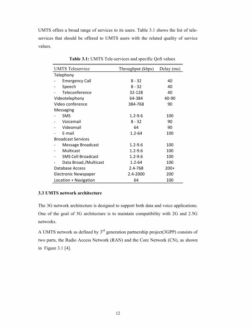
UMTS offers a broad range of services to its users. Table 3.1 shows the list of tele-
services that should be offered to UMTS users with the related quality of service
values.
Table 3.1: UMTS Tele-services and specific QoS values
UMTS Teleservice Throughput (kbps) Delay (ms)
Telephony
- Emergency Call 8 - 32 40
- Speech 8 - 32 40
- Teleconference 32-128 40
Videotelephony 64-384 40-90
Video conference 384-768 90
Messaging
- SMS 1.2-9.6 100
- Voicemail 8 - 32 90
- Videomail 64 90
- E-mail 1.2-64 100
Broadcast Services
- Message Broadcast 1.2-9.6 100
- Multicast 1.2-9.6 100
- SMS Cell Broadcast 1.2-9.6 100
- Data Broad./Multicast 1.2-64 100
Database Access 2.4-768 200+
Electronic Newspaper 2.4-2000 200
Location + Navigation 64 100
3.3 UMTS network architecture
The 3G network architecture is designed to support both data and voice applications.
One of the goal of 3G architecture is to maintain compatibility with 2G and 2.5G
networks.
A UMTS network as defined by 3rd generation partnership project(3GPP) consists of
two parts, the Radio Access Network (RAN) and the Core Network (CN), as shown
in Figure 3.1 [4].

13
Figure 3.1: UMTS Network Architecture
The CN consists of the Circuit Switched (CS) and Packet Switched (PS) domains.
Voice related traffic is handled by the CS domain, while PS domain handles the
packet transfer. The Home Subscriber Server (HSS) holds user information for both
domains.
The Mobile-services Switching Center (MSC) is the bridge between the radio system
and the fixed network in CS domain. MSC consists of two parts, the gateway MSC
(GMSC) and the Visitor MSC (VMSC). The GMSC is located at user’s network,
while the VMSC is located at the network that the user is currently visiting.
In the PS domain, calls are handled by two GPRS Support Nodes (GSN): the
Gateway GSN (SSGN) and the serving GSN (SGSN). The GGSN acts as an IP router
for Internet originated or terminated calls. A UE must firstly attach to the GGSN to
gain an IP connectivity. The UE then created a Packet Data Protocol (PDP) context
at the GGSN, containing the IP address assigned to the user.
The RAN has two connectivity options. The first option is the GSM EDGE RAN
(GERAN) which is based on the Enhanced Data rates for GSM Evolution (EDGE)
technology. The second option is the Universal Terrestrial RAN (UTRAN). UTRAN
manages the UE’s connection with the CN, and consists of Radio Network
Controllers (RNC) and base stations(Node-B).

14

15
4. MULTICAST FRAMEWORK FOR 3G/UMTS
GPRS provides a packet switch platform to transfer packet traffic; however it is not
enough for multimedia applications. Multimedia applications require high amounts
of bandwidth. When many users would like to access the same multimedia
applications at the same time, even in high bandwidth networks like UMTS, the
available radio resources might not be sufficient. Multicasting methods are the most
appropriate methods for such applications. The data is transferred in parallel, sharing
the same resources in multicast methods. One of the technologies that provide
multicasting for 3G wireless networks is Multimedia Broadcast and Multicast
Service (MBMS), proposed by 3GPP.
MBMS is a point-to-multipoint service in which data is transmitted from a single
source entity to multiple recipients. Transmitting the same data to multiple recipients
allows network resources to be shared.
The MBMS bearer service offers two modes of operation:
- Broadcast Mode;
- Multicast Mode.
The MBMS multicast mode is the focus of this thesis. In addition, as an introduction
to MBMS, the broadcast and multicast modes are compared. The multicast mode will
be discussed in greater detail in following sections.
MBMS multicast has some additional requirements for the existing functional
entities of the UMTS architecture.
The broadcast mode refers to a unidirectional point-to-multipoint transmission of
multimedia data from a single source to all users that are located within the defined
broadcast service area. There is no specific requirement to activate or subscribe to
MBMS in broadcast mode. The radio/network resources are used efficiently in
broadcast mode since data is transmitted over a common radio channel.

16
An example of a service using the broadcast mode could be a network welcome
message. As not everybody wants to receive particular services, users can disable the
reception of broadcast service on their User Equipment (UE). The receiver may
suffer data loss since the reception of the traffic is not guaranteed in the broadcast
mode.
The multicast mode is defined as a unidirectional point-to-multipoint transmission of
multimedia data from a single source to all users that are located within the defined
multicast service area. In multicast mode, the radio/network resources are used
efficiently since data is transmitted over a common radio channel. A difference in
multicast mode is that there is a possibility for the network to selectively transmit to
cells within the multicast service area which contains members of a multicast group.
In the multicast mode, users have to subscribe and then join to a particular multicast
group. Figure 4.1 below shows a high level overview of multicast mode network [5].
To understand how MBMS works, section 4.1 details service provision phases and
the following section discusses the architecture.
Figure 4.1: Example of multicast mode network
4.1 MBMS Service Provision Phases
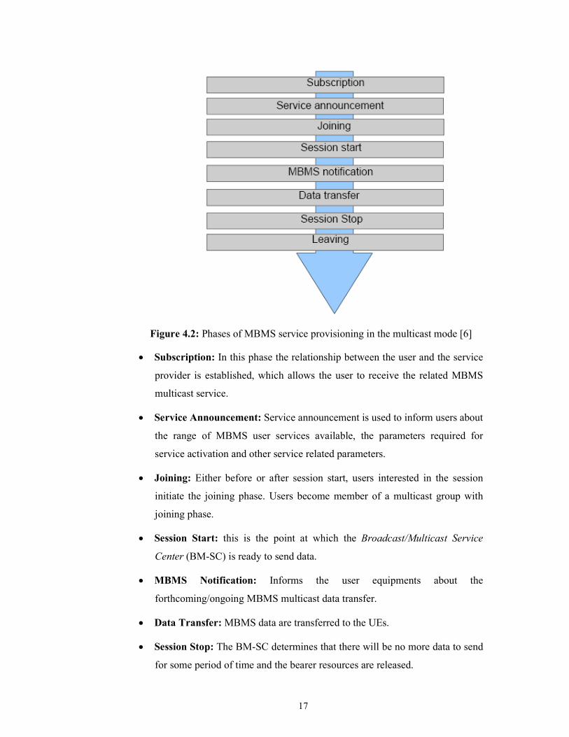
Figure 4.2 shows the phases of MBMS service provisioning and the stages are
described below:
17
Figure 4.2: Phases of MBMS service provisioning in the multicast mode [6]
• Subscription: In this phase the relationship between the user and the service
provider is established, which allows the user to receive the related MBMS
multicast service.
• Service Announcement: Service announcement is used to inform users about
the range of MBMS user services available, the parameters required for
service activation and other service related parameters.
• Joining: Either before or after session start, users interested in the session
initiate the joining phase. Users become member of a multicast group with
joining phase.
• Session Start: this is the point at which the Broadcast/Multicast Service
Center (BM-SC) is ready to send data.
• MBMS Notification: Informs the user equipments about the
forthcoming/ongoing MBMS multicast data transfer.
• Data Transfer: MBMS data are transferred to the UEs.
• Session Stop: The BM-SC determines that there will be no more data to send
for some period of time and the bearer resources are released.
18
• Leaving: A user leaves a multicast group, MBMS deactivation occurs.
4.2 MBMS Architecture
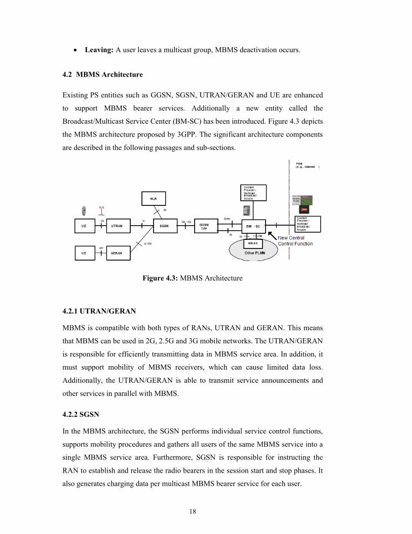
Existing PS entities such as GGSN, SGSN, UTRAN/GERAN and UE are enhanced
to support MBMS bearer services. Additionally a new entity called the
Broadcast/Multicast Service Center (BM-SC) has been introduced. Figure 4.3 depicts
the MBMS architecture proposed by 3GPP. The significant architecture components
are described in the following passages and sub-sections.
Figure 4.3: MBMS Architecture
4.2.1 UTRAN/GERAN
MBMS is compatible with both types of RANs, UTRAN and GERAN. This means
that MBMS can be used in 2G, 2.5G and 3G mobile networks. The UTRAN/GERAN
is responsible for efficiently transmitting data in MBMS service area. In addition, it
must support mobility of MBMS receivers, which can cause limited data loss.
Additionally, the UTRAN/GERAN is able to transmit service announcements and
other services in parallel with MBMS.
4.2.2 SGSN
In the MBMS architecture, the SGSN performs individual service control functions,
supports mobility procedures and gathers all users of the same MBMS service into a
single MBMS service area. Furthermore, SGSN is responsible for instructing the
RAN to establish and release the radio bearers in the session start and stop phases. It
also generates charging data per multicast MBMS bearer service for each user.

19
4.2.3 GGSN
GGSN is the gateway between 3G networks and external networks. In the MBMS
architecture, it is connected to the BM-SC and is a termination point for MBMS GTP
(GPRS Tunnelling Protocol) tunnels. MBMS GTP tunnels are used between GGSN
and SGSN. GGSN links these tunnels via IP multicast with the MBMS data.
4.2.4 BM-SC
The BM-SC is a MBMS specific functional entity, which provides functions for
MBMS user service provisioning and delivery. BM-SC’s functional structure will be
discussed in detail, since it is the most important entity of MBMS architecture.
The BM-SC consists of five sub-functions as illustrated in Figure 4.4.
• Membership function;
• Session and Transmission function;
• Proxy and Transport function;
• Service Announcement function;
• Security function.
Figure 4.4: BM-SC functional structure
The BM-SC Membership function is responsible for user authorization. It provides
authorization for UEs requesting to activate an MBMS service. It may have
subscription data and also may generate charging records for MBMS user services.

20
The Session and Transmission function is responsible for sending data. It is able to
schedule MBMS session transmissions and retransmissions. Furthermore, it marks
each transmission session with an MBMS session identifier. This identifier has two
or three octets and passed at the application layer in the content.
The Proxy and Transport function is a proxy agent for signalling between GGSNs
and other BM-SC sub-functions.
The Service Announcement function provides information about MBMS broadcast
and multicast user services. This information can consist of video and audio
encodings, multicast service identification etc. Service announcements are triggered
by the BM-SC; however it does not have to be sent by the BM-SC. The service
announcement should support the following mechanisms:
• MBMS bearer capabilities to advertise MBMS user services;
• PUSH mechanism (WAP push);
• URL (Uniform Resource Locator) through WAP, HTTP;
• SMS (point-to-point);
• SMS-CB (cell broadcast).
The MBMS security function is essential in multicast mode. MBMS user services
use the Security functions for integrity and confidentiality protection of MBMS data.
It is used for distributing MBMS keys to authorized UEs.
4.3 MBMS Channel Structure in the Radio Access Network (RAN)
MBMS aims to use network and radio resources efficiently, especially in the air
interface of UMTS. MBMS has two transmission modes in the air interface:
• Point-to-point transmission (p-t-p)
• Point-to-multipoint transmission (p-t-m)
Point-to-point transmission, in other words unicast transmission, is used to transport
MBMS traffic between the network and one UE. p-t-p transmission is beneficial for
MBMS service delivery for a limited amount of users.

21
Point-to-multipoint transmission, in other words multicast transmission, is used to
transport MBMS traffic between the network and several UEs. p-t-m transmission is
beneficial for MBMS service delivery when amount of users increases.
There are new added entities and channels to the current UMTS architecture with the
introduction of MBMS, which are used in point-to-multipoint transmission mode.
To support MBMS user and control plane transmission, a multicast functionality is
added, entitled “MAC-m”, to take care of scheduling of MBMS related transport
channels [7]. MAC-m entity provides mapping from MBMS logical channels to
Forward Access Channel (FACH) transport channels and adds MBMS ID in the
MAC for MBMS channels.
New added logical channels are described below:
• MBMS point-to-multipoint Control Channel (MCCH): is used for
transmission of control information including MBMS service information and
bearer information.
• MBMS point-to-multipoint Traffic Channel (MTCH): is used for p-t-m
downlink transmission of traffic information.
• MBMS point-to-multipoint Scheduling Channel (MSCH): is used for
transmission of service scheduling information including service ID, starting time
and ending time.
FACH is used as a transport channel for MTCH, MSCH and MCCH.
S-CCPCH (Secondary Common Control Physical Channel) is used as a physical
channel for FACH carrying MTCH or MSCH or MCCH [7].
MBMS brings a new physical channel, called MBMS Notification Indicator Channel
(MICH). MICH informs UEs of an upcoming change in the MCCH information.
Figure 4.5 illustrates the new added MBMS entities and channels.

22
Figure 4.5: New added MBMS entities and channels
It is worth mentioning about the usage of these channels in p-t-p and p-t-m
transmission modes. In the case of p-t-p transmission, multiple Dedicated Channels
(DCH) are used. DCH is a channel dedicated to one UE for uplink or downlink
transmission. On the other hand, single FACH is used in p-t-m transmission. The
3GPP MBMS Counting Mechanism is used to determine the optimum transmission
mode for a given service [7]. According to this mechanism, a switch from p-t-p to p-
t-m mode occurs when the number of users and as a result to number of users,
downlink transmission power in a cell exceeds a predefined threshold. The threshold
can be also determined by the operator. The MBMS p-t-p / p-t-m switching strategies
defined in [8] suggests that High Speed Downlink Shared Channel (HS-DSCH) can
be used instead of DCH in p-t-p transmission mode. HS-DSCH is a transport channel
of High Speed Downlink Packet Access (HSDPA) technology and it is relatively a
new proposal, still under investigation [9].
4.3.1 Macro diversity and combining technologies for MBMS
The target of MBMS is to make an efficient usage of network and radio resources,
especially in the air interface of UMTS. These are directly relevant to the power
control strategies. Power control is one of the key aspects of MBMS and, since base
stations’ power is limited. A new technique, called macro-diversity is propesed as an
enhancement to the UMTS 3GPP Release 6 MBMS. It is used to improve the
physical layer performance of MBMS by combining of transmissions from multiple
cells. Two combining technologies are supported for MBMS, selective combining
and soft combining as illustrated in Figure 4.6.

23
Figure 4.6: Combining Technologies
Selective combining decodes the MBMS data received from each cell individually.
Combining is performed at Radio Link Control (RLC) layer. The diversity gain is in
the order of 2-3 dB reduction in transmission power compared to single cell
reception.
Soft combining is performed at physical layer. The relative delay between the radio
links to be combined, when they are received by the UE, must be no more than
(1 TTI)+(1 slot). Relative to selective combining, the gain is in the order of 4-6 dB
[10]. From a performance perspective soft combining is preferable as it provides
higher gains compared to selective combining.
Figure 4.7 illustrates the gain in power control for radio bearers of 64 kbps for the
case with and without soft combining. Also a 128 kbps bearer requires nearly twice
as much transmit power as a 64 kbps radio bearer.

24
Figure 4.7: Estimated coverage vs. fraction of total power with Soft Combining (VehA3 64 kbps, 80 ms TTI, 1% BLER) [10]
Table 4.1 shows the power consumption required per 64 kbps radio bearer and
MBMS channel capacity on a 5 MHz carrier with and without diversity.
Table 4.1: Power consumption and MBMS channel capacity with combining technologies [11]
MBMS channel capacity on a 5 MHz carrier
Combining Technologies Power Consumption for 64 kbps
64 kbps 128 kbps 256 kbps
No Macro Diversity 14% ~ 33% 2 ~ 6 <= 2 -
Selective Combining 9.8% ~ 13.2% 6 ~ 8 <= 4 < 2
Soft Combining 4.7% ~7.6% 10 ~ 17 <= 8 <= 3
Table 4.1 shows that the use of soft combining significantly reduces the transmit
power requirement for one 64 kbps MBMS channel to 4.7% of the Node-B power.
4.4 MBMS Services
Three functional layers are defined for the delivery of MBMS services. They are
Bearer, Delivery and User services. Functional layers for MBMS service delivery is
shown in Figure 4.5.

25
Figure 4.5: Functional layers for MBMS User Service
Bearers provide the information transmission path for IP data. MBMS bearers are
used to transport multicast and broadcast traffic. Two delivery methods are defined,
namely download and streaming. Delivery methods may use either MBMS bearers
for content delivery or unicast bearers through a set of MBMS associated procedures.
MBMS user services are built on top of bearer services and delivery methods.
MBMS User Services can be classified according to the method used to distribute
them. There are four types of user services targeted by MBMS.
• Streaming Services:
Streaming means continuous data flow providing a stream of continuous
media, like audio and media, is a basic MBMS User Service.
• File Download Service:
This service basically delivers binary data over an MBMS bearer. Users
interested in an application activate the related application through his/her
terminal and utilizes the delivered data. The most important functionality for
this service is reliability; a user must receive all the data sent in the proper
order to utilize from the service.
• Carousel Service:
Carousel Services combines both aspects of both the streaming and file
download services described above. Similar to the streaming service, this
service also includes time synchronisation. Target of this service is static
media. The benefits of this service are delivering content and by repeating or
updating the transmission of the data periodically. This service is possible
over a low bit-rate bearer.

26
Video on Demand (VoD) services can be classified within carousel service. It
allows the users to get streamed or downloaded content of their choice from a
content server.
• Television (TV) Service:
The Television service is an MBMS service consisting of synchronised
streaming audio and visual components [12]. A user can select between
different content within the MBMS Television Service.
Streaming service will be discussed in detail in following sections. File download
and carousel services are outside the scope of the thesis.
4.5 MBMS Streaming Delivery Method
MBMS streaming delivery method is used to deliver continuous multimedia data (i.e.
speech, audio and video) over an MBMS bearer service. Streaming delivery method
is useful for MBMS user services that require the delivery of scheduled multicast and
broadcast streaming content.
MBMS streaming delivery method protocol stack is shown in Figure 4.6. The grey-
shaded protocols and functions; MBMS security functions and the usage of SRTP are
outside the scope of this thesis.
Figure 4.6: Protocol stack view for MBMS streaming delivery method
The transport protocol for MBMS streaming delivery is Real-Time Transport
Protocol (RTP). RTP operates on top of User Datagram Protocol (UDP) and is

27
already used for the transport of Packet switched Streaming Service (PSS) in 3GPP.
RTP is used in conjunction with the Real-Time Transport Control Protocol (RTCP).
RTCP provides feedback about the transmission quality. Only transmissions of
RTCP packets are allowed, since MBMS bearer services are unidirectional.
The following RTP payload formats are used for RTP/UDP/IP transport of
continuous media:
• AMR narrow-band speech codec
• AMR wideband speech codec
• Extended AMR-WB codec
• Extended aacPlus codec
• H.264 (AVC) video codec RTP payload format. An MBMS client supporting
H.264 (AVC) is required to support the following three packetization modes:
single NAL unit mode, non-interleaved mode and interleaved mode [13].
The forward error correction (FEC) decoder tries to reconstruct the initial FEC
source block using the FEC source and repair packets.
Session Description Protocol (SDP) is a format for describing streaming media
initialization parameters. It includes session announcement, session invitation
and other forms of multimedia session initiation. SDP is provided to the MBMS
client via announcement procedure to describe the streaming delivery session.
Figure 4.7 is an example of an MBMS streaming session description based on
SDP.
Session Parameters
Video Stream
Parameters
Figure 4.7: An Example of MBMS SDP
v=0
o=ghost 2890844526 2890842807 IN IP4 192.168.10.10
s=3GPP MBMS Streaming SDP Example
i=Example of MBMS streaming SDP file
u=http://www.infoserver.example.com/ae600
c=IN IP6 FF1E:03AD::7F2E:172A:1E24
t=3034423619 3042462419
b=AS:77
a=mbms-mode:broadcast 1234 1
a=source-filter: incl IN IP6
*2001:210:1:2:240:96FF:FE25:8EC9
a=FEC-declaration:0 encoding-id=1
m=video 4002 RTP/AVP 96
b=TIAS:62000
b=RR:0
b=RS:600
a=maxprate:17
a=rtpmap:96 H264/90000
a=fmtp:96 profile-level-id=42A01E; packetization-mode=1
28
Audio Stream
Parameters
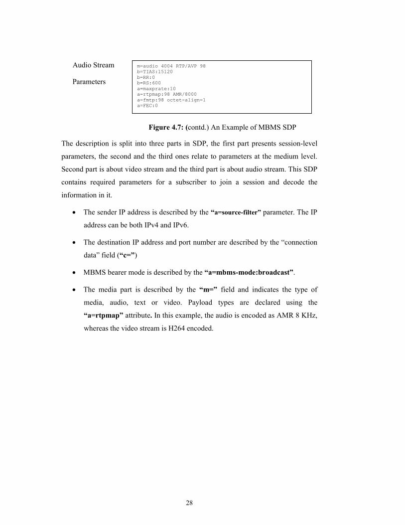
Figure 4.7: (contd.) An Example of MBMS SDP
The description is split into three parts in SDP, the first part presents session-level
parameters, the second and the third ones relate to parameters at the medium level.
Second part is about video stream and the third part is about audio stream. This SDP
contains required parameters for a subscriber to join a session and decode the
information in it.
• The sender IP address is described by the “a=source-filter” parameter. The IP
address can be both IPv4 and IPv6.
• The destination IP address and port number are described by the “connection
data” field (“c=”)
• MBMS bearer mode is described by the “a=mbms-mode:broadcast”.
• The media part is described by the “m=” field and indicates the type of
media, audio, text or video. Payload types are declared using the
“a=rtpmap” attribute. In this example, the audio is encoded as AMR 8 KHz,
whereas the video stream is H264 encoded.
m=audio 4004 RTP/AVP 98
b=TIAS:15120
b=RR:0
b=RS:600
a=maxprate:10
a=rtpmap:98 AMR/8000
a=fmtp:98 octet-align=1
a=FEC:0
29
5. MOBILE MULTIMEDIA AND STREAMING
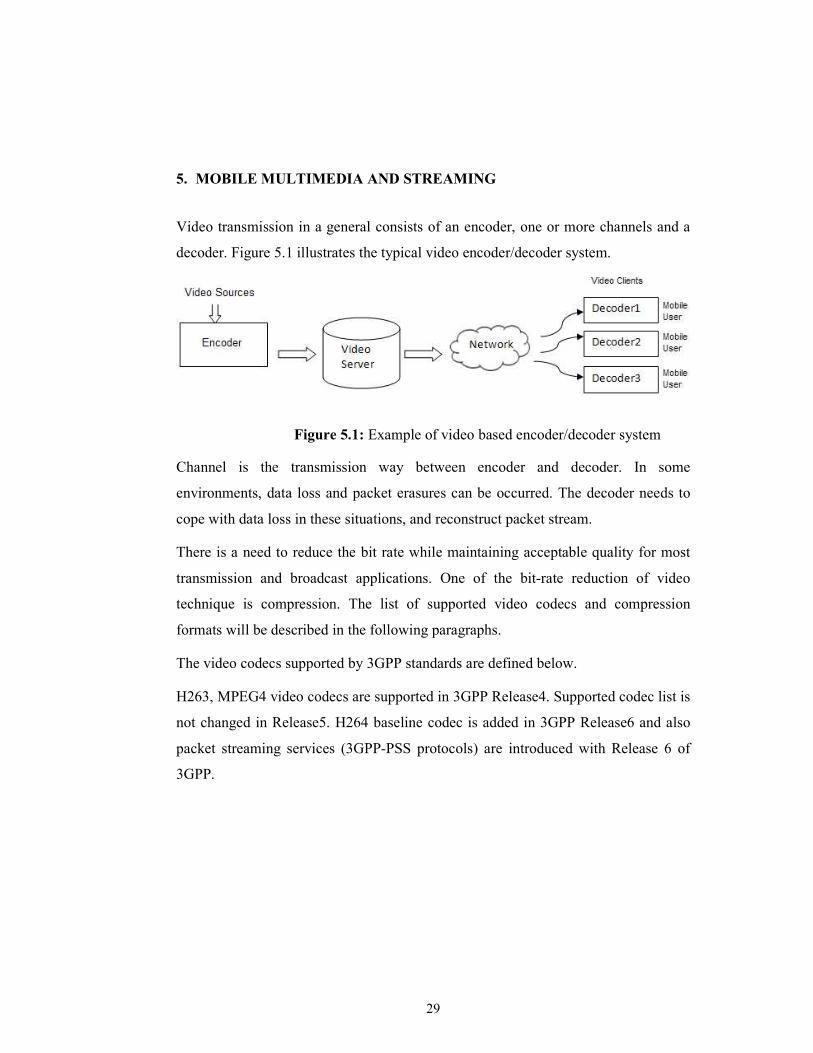
Video transmission in a general consists of an encoder, one or more channels and a
decoder. Figure 5.1 illustrates the typical video encoder/decoder system.
Figure 5.1: Example of video based encoder/decoder system
Channel is the transmission way between encoder and decoder. In some
environments, data loss and packet erasures can be occurred. The decoder needs to
cope with data loss in these situations, and reconstruct packet stream.
There is a need to reduce the bit rate while maintaining acceptable quality for most
transmission and broadcast applications. One of the bit-rate reduction of video
technique is compression. The list of supported video codecs and compression
formats will be described in the following paragraphs.
The video codecs supported by 3GPP standards are defined below.
H263, MPEG4 video codecs are supported in 3GPP Release4. Supported codec list is
not changed in Release5. H264 baseline codec is added in 3GPP Release6 and also
packet streaming services (3GPP-PSS protocols) are introduced with Release 6 of
3GPP.

30
5.1 MPEG4 Compression Format
The aim of the MPEG-4 family of standards is to develop compression algorithms
for new applications such as streaming and multimedia file transfer. MPEG-4
provides very efficient video coding covering the range from 5 to 64kbps for QCIF
video. MPEG-4 uses different approach to video compression while compared with
the approach used in MPEG-1 and MPEG-2. MPEG-4 is object-based; each scene is
composed of video objects (VOs) that are coded individually.
There are three main profiles for MPEG-4: simple, core and main profile. The
MPEG-4 visual simple profile is the supported standard for video and audio
transmission over mobile networks for 3GPP Release 5.
MPEG-4 is achieved high efficiency of video and audio coding which led it to use
increasingly in various applications IP and streaming TV applications, including
mobile TV. Applications of MPEG-4 include real-time communications, digital
television, mobile multimedia, virtual meetings, broadcasting etc.
MPEG-4 has 22 parts defining various attributes of the standard. Some examples of
these parts are Carriage over IP Networks (MPEG-4 Part 8), AVC File Format
(MPEG-4 Part 15) and Advanced Video Coding (MPEG-4 Part 10, now standardized
as H.264/AVC).
5.2 H.263 Video Compression Format
The leading international standards which have been recently adopted for video
compression are: Joint Photographers Expert Group (JPEG), International
Telecommunications Union – Telecommunication Standards Sector (ITU-T) H.26x,
Motion Picture Experts Group type 1 (MPEG x). The general source model used in
these standardized coding algorithms provides a basic and incomplete description of
video scenes. Good picture quality is obtained at high bit-rate communications.
Further coding improvements are required to reach acceptable video quality at low
bit-rates. ITU-T decided to develop low bit-rate video coding algorithm, namely
H.263.
31
The objective for H.263 was to provide better picture quality at low bit-rates, than
the existing ITU-T algorithms for video compression. Target networks of H.263 are
low bit-rate networks like Public Switched Telephone Network (PSTN), Integrated
Services Digital Network (ISDN) and wireless networks.
5.3 H.264/AVC
H.264/AVC (Advanced Video Coding) is a video compression standard jointly
developed by the ITU-T Video Coding Experts Group (VCEG) and the ISO/IEC
Moving Pictures Experts Group (MPEG). The main objectives of the H.264/AVC are
improved video compression efficiency and better network adaptation. These are
achieved by designing H.264/AVC in two layers, the video coding layer (VCL) and
the network abstraction layer (NAL). The use of network abstraction layer and lower
bit rates makes the H.264/AVC ideally suited to be used in wireless multimedia
networks, UMTS and other packet-based transport media.
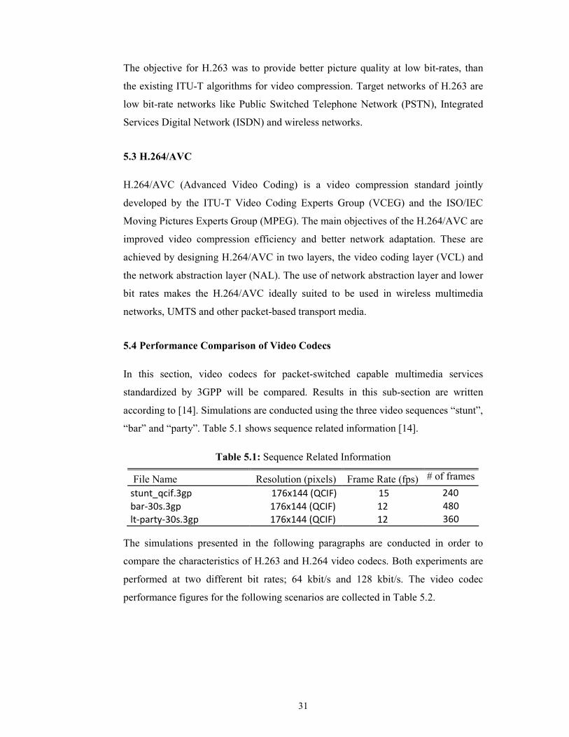
5.4 Performance Comparison of Video Codecs
In this section, video codecs for packet-switched capable multimedia services
standardized by 3GPP will be compared. Results in this sub-section are written
according to [14]. Simulations are conducted using the three video sequences “stunt”,
“bar” and “party”. Table 5.1 shows sequence related information [14].
Table 5.1: Sequence Related Information
File Name Resolution (pixels) Frame Rate (fps) # of frames
stunt_qcif.3gp 176x144 (QCIF) 15 240
bar-30s.3gp 176x144 (QCIF) 12 480
lt-party-30s.3gp 176x144 (QCIF) 12 360
The simulations presented in the following paragraphs are conducted in order to
compare the characteristics of H.263 and H.264 video codecs. Both experiments are
performed at two different bit rates; 64 kbit/s and 128 kbit/s. The video codec
performance figures for the following scenarios are collected in Table 5.2.

32
Table 5.2: H.263 and H.264 Video Codec Performance Comparison
Codec Sequence Bit Rate (kbit/s) APSNR (dB)
H.263 1 Stunt 64 27.34
H.263 1 Stunt 128 30.46
H.263 2 Bar 64 30.12
H.263 2 Bar 128 33.13
H.263 3 Party 64 27.73
H.263 3 Party 128 30.68
H.264 1 Stunt 64 28.38
H.264 1 Stunt 128 31.96
H.264 2 Bar 64 30.79
H.264 2 Bar 128 34.34
H.264 3 Party 64 28.16
H.264 3 Party 128 31.65
As stated in Table 5.1, simulations were carried out under the following conditions.
• The video sequence length of the “stunt” file is 240 frames.
• The video sequence length of the “bar” file is 480 frames.
• The video sequence length of the “party” file is 360 frames.
The image quality expressed in Average Peak Signal-to-Noise Ratio (APSNR)
improved almost linearly as the bit rate is increased. As can be seen from Table 5.2,
the performance of H.264 codec is significantly better than H.263 codec, when
compared at the same bit rate scenarios.
5.5 Streaming
Streaming refers to the transmission of multimedia data over telecommunication
networks. The number of applications using streaming technologies over wired and
wireless networks has experienced a high increase in the last years. The target of
using streaming technologies is to connect as many users as possible and to provide
network services at lower costs and higher quality.
Streaming is made possible by high compression codecs. Additional reqiurements are
imposed for the devices, both servers and terminals, involved in the coding-decoding
process. These requirements are particularly demanding mobile applications. The
mobile terminal has to be cheap, small and consume low power.
Streaming involves the following steps:
• Media compression and encoding

33
• Conversion to streaming format
• Stream serving and transport over IP networks
• Stream decoding and playing on a media player
The files need to have timing control information even if they are streaming in real
time. The timing control information can be used by the server to manage delivery
rate. For this purpose the captured files are converted to the streaing format, which
adds the timing control function.
The streaming applications uses multimedia real time file exchange protocols that
was defined by the Internet Engineering Task Force (IETF) standardization body.
These include the Real Time Protocol (RTP) and the Real Time Streaming Protocol
(RTSP). RTP is one of the most adopted transmission protocols for media streaming.
A higher level protocol has been designed on top of RTP, which iscalled RTSP. It
supports VCR-like functions, such as play, forward, reverse and pause while
watching the video. The main advantage of RTSP is that it does not need to always
keep the connection alive. The protocol is able to keep the state of the stream and
start downloading again upon a user’s request.
5.5.1 Streaming application in 3G networks
Streaming has been standardized for 3G networks under the 3GPP packet-switched
streaming. Figure 5.2 presents the user plane protocol stack of a 3GPS multimedia
terminal, explaining the transport of different media types [15].
Figure 5.2: User Plane Protocol Stack for 3GPP-PSS

34
5.6 File Formats for Mobile Multimedia
The file formats that are supported in mobile multimedia environment have been
specified by the 3GPP. The file formats are based on MPEG-4, H.263 and
H.264/AVC coding standards.The files used in GSM, 2.5G and 3G Wideband Code
Division Multiple Access (WCDMA) networks are denoted by .3gp. Many of the
mobile phones for 3G support additional file formats, such as Windows Media
(.wmv and .wma files), Microsoft Mobile Office files .ppt, but these are not
mandated by the 3GPP. The available e-mail clients can send these files as
attachements.
3GPP file formats (.3gp) are based on the ISO-based file format, which is the
primary standard for MPEG-4 based files. 3GPP file format is a simpler version of
the ISO file format supporting only video in H.263, MPEG-4 and H.264/AVC.
35
6. OVERVIEW OF TECHNOLOGIES FOR MOBILE TV
Mobile TV refers to constant TV being provided to mobile terminals. Mobile TV
combines mobile technology with mobile content and expends the universe of
television by allowing TV to be consumed on the go.
Mobile TV can also be delivered through one-way dedicated broadcast networks.
There are different standards or technologies that allow mobile TV to be transmitted
using broadcast technology. The standards and alternative technologies include
Internet Protocol Datacasting (IPDC), Digital Video Broadcasting Handheld (DVB-
H) which is the basis for the IPDC technology, MediaFLO which is developed by
Qualcomm company, Digital Multimedia Broadcasting (DMB) and Terrestrial
Integrated Services Digital Broadcasting (ISDB-T). The details of these alternative
technologies are described in detail in the following sub-sections.
6.1 Requirements for Mobile TV Services
The following four requirements are the most important items for the adoption of
mobile TV services [16].
1. Handset integration and usability
2. Technical performance and reliability
3. Usability of the mobile TV service
4. Satisfaction with the content
Mobile TV should be available in every location the consumers might expect to
receive it (e.g., on public transport, in a waiting room, at work, etc.). Home use is the
most prevalent context for Mobile TV watching. Although standard TV is available
at home, subscribers want to have their own control what is watched without the
need to negotiate with other family members. Another reason for the popularity of
home use is that the user can control where content is watched. On the other hand,
delay between the live broadcast TV signal and the mobile TV signal (approx. 1 min)
disadvantages the mobile audience for using mobile TV.

36
Subscribers want large screens, but they don`t want their phones to be too big since
they carry the mobile phones with them wherever they go. Mobile phones screens
should have high contrast and a high viewing angle to support viewing in diffucult
circumtances. Transmission in formats should be ideally suited to mobile phones,
e.g., QCIF or QVGA resolution with high efficiency coding. Some research results
have shown that contents displayed on mobile phones at higher resolutions and larger
sizes is generally more acceptable than lower resolutions and smaller sizes.
Mobile phones capable of using mobile TV content should use low power
consumption technology. Mobile TV applications should provide warnings when the
battery is drained beyond a certain threshold. The applications should alert users of
incoming calls, messages while watching TV.
Mobile phones should support mobility and ability to watch TV while travelling.
There should be minimum loss of signal while roaming. Mobile TV applications
need to be able to deal with roaming events.
The content distributed to mobile phones can be considered in two services, namely
Live TV and Interactive TV.
Live TV offers streaming access to standard TV channles. The subscriber can choose
from a selection of channels using an Electronic Program Guide (EPG). EPG is an
on-screen guide to scheduled programs, allowing a viewer to navigate, select and
discover content by channel, time, etc. The time spent on watching Live TV is
shorter than with standard TV.
Interactive TV gives users the opportunity to get involved with a TV show by voting.
This service allows users to provide real-time feedback during TV shows.
6.2 Alternative Mobile TV Technologies
In this section, alternative technologies for Mobile TV will be introduced. There are
a number of technologies that have been developed and are either at a commercial or
trial stage around the world. It is useful to classify mobile TV technologies as
depicted in Figure 6.1.

37
Mobile TV services can be summarized under three networks. These are 3G
networks, terrestrial and satellite broadcast networks and broadband wireless
networks. The technologies MBMS, which is described in the previous chapters,
IPDC, MediaFLO, DMB (S-DMB, a satellite-based technology, and T-DMB, a
terrestrial-based technology) and ISDB-T are competing to emerge as the dominant
technology standard in mobile television. In the following sections, detailed
information will be provided for each of the technologies. Since MBMS is defined in
the previous sections, it will not be mentioned again in this section.
6.2.1 IPDC and DVB
IPDC is a terrestrial broadcast mobile TV technology. DVB-H is the basis for the
IPDC technology. In general, terrestrial broadcast mobile TV services do not allocate
spectrum form the 3G pool. It is possible to transmit data at a rate of 22Mbit/s with
broadcast and this is enough to provide over 50 high quality TV channels. DVB-H
solutions generally operate in the Very High-Frequency (VHF) and Ultra High-
Frequency (UHF) bands of terrestrial television. It uses 6,7 and 8 MHz bandwidth.
IPDC carries IP datagrams over a broadcast network, which is suitable for
transmitting high quality audio/video streams. Figure 6.2 shows the protocol stack of
IP datacast [17].
Figure 6.1: Mobile TV alternative technologies

38
Figure 6.2: Protocol Stack for IP Datacast
Figure 6.2: Protocol Stack of IP Datacast
The purpose for developing DVB-H was to use a digital television broadcast network
to transmit the data. Digital content is encapsulated into IP packets and then they can
be delivered in a reliable manner. IPDC is suitable for carrying live video, music
files, video downloads (via file transfer), audio and video streams (in streaming
format) or other types of content. Internet protocol with UDP is responsible for data
transmission, while PSI/SI is used for DVB signalling.
Two protocols are used in the application layer, FLUTE and ALC/LCT. FLUTE is
designed for data transmissions. The broadcast data consists of two types; the
broadcast content and the service description, such as PSI/SI data and an electronic
service guide. Electronic Service Guide (ESG) assist users in discovering and
selecting multicast and broadcast service content.
MPEG-2 TS Data Link Layer
Physical Layer
IP PSI/SI Network Layer
UDP Transport Layer
ALC/LCT RTP
FLUTE
Application Layer
FLUTE: File Delivery over Unidirectional Transport
ALC/LCT: Asynchronous Layered Coding/Layered Coding Transports
PSI/SI: Program Specific Information/Service Information
TS: Transport Stream

39
DVB-H does not provide any interactivity and there is no uplink communication , or
return channel in the standard. The availability of a return channel allows users to
dynamically request the delivery of a particular broadcast service. An interaction
channel realized by a return link also allows the operator to offer more enhanced
services to their customers[18]. By interactive services, the operators can receive
feedback from the users through polls and voting. All of these requirements can be
met with the use of existing cellular networks, since the devices we are interested in
are mobile phones. Implementation of interaction channel is depicted in Figure 6.3.
Figure 6.3 : Implementation of Interaction Channel
6.2.2 MediaFLO
MediaFLO is a unicast transmission system based on the FLO (Forward Link Only)
technology. Both MediaFLO and FLO were developed in the USA by Qualcomm
Inc. Unlike MBMS or DVB-H, MediaFLO is developed as a closed standard.
MediaFLO and DVB-H look similar, and MediaFLO is the most promising
alternative among other broadcast technologies. It operates in the UHF, VHF and L
bands in channels of 5,6,7 and 8MHz bandwidth, similar to DVB-H. The available
data rates range from 0.47 up to 1.87 bit/s per Hz. This means that the FLO physical
layer can achieve up to 11.2 Mbit/s transmission speed in a 6 MHz bandwidth.

40
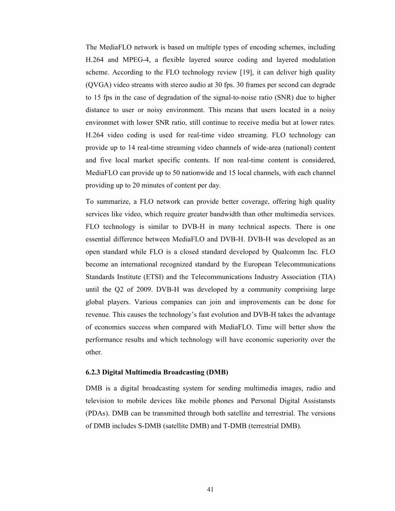
A FLO system is composed of four sub-systems: the Network Operations Center,
FLO transmitters, 3G Network and FLO-enabled mobile devices. Figure 6.4 shows
the FLO architecture.
Figure 6.4: FLO technology architecture
The network operations center is the most significant element and consists of a
National Operations Center (NOC) and one or more Local Operations Center (LOC).
It’s responsibilities include the distribution, billing and content management. It also
serves as an acces point for national and local content providers to distribute program
guide information to mobile devices. Moreover, the Network Operations Center
manages user’s subscriptions, delivery of access and encryption keys and provides
billing information to cellular operators. LOCs serve as an access point from which
local content providers can distribute local content to mobile devices in the
associated market area [19].
41
The MediaFLO network is based on multiple types of encoding schemes, including
H.264 and MPEG-4, a flexible layered source coding and layered modulation
scheme. According to the FLO technology review [19], it can deliver high quality
(QVGA) video streams with stereo audio at 30 fps. 30 frames per second can degrade
to 15 fps in the case of degradation of the signal-to-noise ratio (SNR) due to higher
distance to user or noisy environment. This means that users located in a noisy
environmet with lower SNR ratio, still continue to receive media but at lower rates.
H.264 video coding is used for real-time video streaming. FLO technology can
provide up to 14 real-time streaming video channels of wide-area (national) content
and five local market specific contents. If non real-time content is considered,
MediaFLO can provide up to 50 nationwide and 15 local channels, with each channel
providing up to 20 minutes of content per day.
To summarize, a FLO network can provide better coverage, offering high quality
services like video, which require greater bandwidth than other multimedia services.
FLO technology is similar to DVB-H in many technical aspects. There is one
essential difference between MediaFLO and DVB-H. DVB-H was developed as an
open standard while FLO is a closed standard developed by Qualcomm Inc. FLO
become an international recognized standard by the European Telecommunications
Standards Institute (ETSI) and the Telecommunications Industry Association (TIA)
until the Q2 of 2009. DVB-H was developed by a community comprising large
global players. Various companies can join and improvements can be done for
revenue. This causes the technology’s fast evolution and DVB-H takes the advantage
of economies success when compared with MediaFLO. Time will better show the
performance results and which technology will have economic superiority over the
other.
6.2.3 Digital Multimedia Broadcasting (DMB)
DMB is a digital broadcasting system for sending multimedia images, radio and
television to mobile devices like mobile phones and Personal Digital Assistansts
(PDAs). DMB can be transmitted through both satellite and terrestrial. The versions
of DMB includes S-DMB (satellite DMB) and T-DMB (terrestrial DMB).

42
DMB was developed in South Korea under the national IT project. The world’s first
offical mobile TV service started in South Korea in 2005, although trials were
carried out much more earlier. DMB services are based on an enhancement of the
DAB (Digital Audio Broadcasting) which is a standard for radio broadcasting.
DMB and DAB uses frequency channels of 1.536 MHz bandwidth and net data rates
between 1 and 1.5 Mbps. DMB can operate in different frequency ranges between 30
MHz and 3 GHz in the electromagnetic spectrum. Common frequency bands used for
T-DMB are band III (174-240 MHz) and L band (1452-1492 MHz), and S-DMB
uses S Band (2605-2655 MHz).
DMB has a video service and it enables the transmission of TV programs to mobile
devices. Mobile TV programs can be encoded using different resolutions. Some of
the supported resolutions are CIF (352 x 288 pixels), QCIF (176 x 240 pixels) and
WDF (384 x 224 pixels). All resolutions can be applied with a frame rate of 30 fps.
DAB has been adopted as a European standard by ETSI in 2005 [20] and also ITU
chose to adopt T-DMB as the standard in fourth quarter of 2006. After the launch of
services in Korea, Mobiles Fernsehen Deutschland (MFD) in Germany deployed T-
DMB for the FIFA World Cup 2006. Mobile TV services based on T-DMB were
available in six cities in Germany by the end of 2007.
An advantage of DMB is that it can be realized by the existing DAB infrastructure,
which is already established in many countries. It is not required to establish a
dedicated infrastructure and prevent service providers from paying high roll-out
costs.
6.2.4 Terrestrial Integrated Services Digital Broadcasting (ISDB-T)
ISDB-T was developed in the late 1990s in Japan. The system is designed to provide
reliable high-quality video, audio and data broadcasting for fixed and mobile
receivers.
43
ISDB-T system uses MPEG-2 Transport Stream for multiplexing of digital audio and
video to synchronize the output, like DVB-T. ISDB-T uses a modulation scheme
referred to as segmented transmission OFDM (orthogonal frequency-division
multiplexing). This modulation scheme splits a transmission band into fourteen equal
segments. Thirteen of these OFDM segments can be used for transmission of
broadcast services, with the transmission parameters for each segment being
individually configured. Based on the transmission configuration, a receiver can
selectively receive segments of the signal without requiring decoding and reception
of the complete signal transmitted over the whole bandwidth of the channel [18]. The
partial reception of the signals provide significant power savings, and making it
suitable for mobile devices.
ISDB-T can operate within the 6 MHz bandwidth. In such a configuration two or
three SDTV, or one HDTV channels can be transmitted. In addition, ISDB provides
interactive services with data broadcasting, including the EPG (Electronic Program
Guide). Moreover, it is claimed that ISDB-T allows HDTV to be received in moving
vehicles at over 100 km/h.
6.2.5 Comparison of Mobile TV technologies
In general the following parameters are important for comparing the technologies:
• Efficient spectrum utilization;
• Handset features;
• Power-saving features;
• Channel switching times;
• Quality of service in indoor and outdoor environments and while roaming;
• Cots of services.
44
Any comparison of Mobile TV technologies described in this thesis is a difficult task
as there are a number of constraints. An example of a constraint is spectrum
availability. By classifying broadcast and multicast technologies, it can be said that
DVB-H and MediaFLO are the leading broadcast systems. On the other hand, DMB
and ISDB-T appear to be regional solutions. MBMS allows service providers to use
the existing spectrum and cellular networks in order to offer mobile TV services. By
this reason, MBMS should not be compared with broadcast technologies, but rather
as a complementary standard.
6.3 Spectrum for Mobile TV
The radio spectrum is widely used for radio and television broadcasting and by the
military and is essential for a broad range of other activities including medical
diagnosis, transportation, astronomy, energy and global positioning among others.
The spectrum is a major component of the telecommunications industry. The
spectrum standardization, spectrum allocation and spectrum availability are of the
highest importance.
Spectrum management is driven by ITU-R (ITU-Radio Communication). World
Radio Conference (WRC) holds a conference every two or three years to make
worldwide recommendations on the allocation of spectrum for varying services. The
individual countries are then responsible for making allocations within their own
country based on criteria that they wish, according to WRC tables. Although WRC
holds meeting periodically, it is not ideally suited to services such as mobile TV and
multimedia broadcasting, which are growing rapidly. The increasing need for
spectrum and the urge to deploy services as soon as possible leads to a situation
where country-specific approaches are quite common. These always do not align
with the gloabal strategy. When solutions like DVB-H and DMB is taken into
consideration, which are competing for the same spectrum resources, the situation is
getting more complicated. On the other hand, the lack of spectrum may prevent the
development of these technologies. The use of spectrum for mobile TV is depicted in
Figure 6.5.
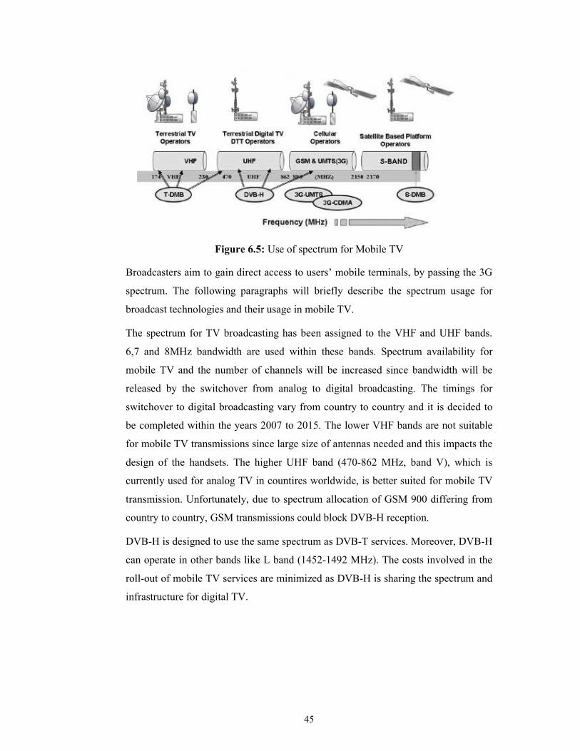
45
Figure 6.5: Use of spectrum for Mobile TV
Broadcasters aim to gain direct access to users’ mobile terminals, by passing the 3G
spectrum. The following paragraphs will briefly describe the spectrum usage for
broadcast technologies and their usage in mobile TV.
The spectrum for TV broadcasting has been assigned to the VHF and UHF bands.
6,7 and 8MHz bandwidth are used within these bands. Spectrum availability for
mobile TV and the number of channels will be increased since bandwidth will be
released by the switchover from analog to digital broadcasting. The timings for
switchover to digital broadcasting vary from country to country and it is decided to
be completed within the years 2007 to 2015. The lower VHF bands are not suitable
for mobile TV transmissions since large size of antennas needed and this impacts the
design of the handsets. The higher UHF band (470-862 MHz, band V), which is
currently used for analog TV in countires worldwide, is better suited for mobile TV
transmission. Unfortunately, due to spectrum allocation of GSM 900 differing from
country to country, GSM transmissions could block DVB-H reception.
DVB-H is designed to use the same spectrum as DVB-T services. Moreover, DVB-H
can operate in other bands like L band (1452-1492 MHz). The costs involved in the
roll-out of mobile TV services are minimized as DVB-H is sharing the spectrum and
infrastructure for digital TV.

46
A similar situation exists with T-DMB, which is an enhancement of the DAB
standards. Common frequency bands used for T-DMB are band III (174-240 MHz)
and L band (1452-1492 MHz), and S-DMB uses S Band (2605-2655 MHz). T-DMB
is designed to use the DAB spectrum, which has been allocated in many countries.
Commercial T-DBM services were launched in South Korea in 2005, for mobile TV
and multimedia broadcast. The spectrum for the services was allocated in the band
III (174-240 MHz). After the alunch of services in South Korea, MFD in Germany
deployed T-DMB in 2006. The T-DMB services in Germany operated in the L band
(1452-1492 MHz), which is the satellite allocation for DAB services.
6.3.1 Spectrum for 3G/UMTS technologies
The UMTS uses the 2 GHz band. The frequency bands used in Europe are 1900 –
2025 for uplink and 2110 – 2200 for downlink as shown in Figure 6.6.
Figure 6.6: European Frequency Allocations for UMTS
MBMS uses existing 3G networks. This allows operators to capitalize on their
current investment and utilize existing spectrum allocations and network coverage.
3G networks can be integrated to MBMS without additional spectrum and system
requirements, other than software upgrades.
47
6.4 Terminals for Mobile TV
It is worth mentioning about the terminal manufacturers and software vendors. As
more multimedia features are introduced, manufacturers and software vendors should
enhance the terminal capabilities to support these new features. The following
functionalities are needed for a mobile phone to handle new multimedia services and
mobile TV service.
• Processor and Memory: Higher processors and memory are needed for
advanced multimedia applications. The memory in phones reached higher
values like 8GB and 16GB.
• Chip Sets: Chips designed for digital TV broadcasting in DVB-H or ISDB-T
formats contains the tuner (UHF or L band), OFDM demodulator, and DVB-
H or ISDB-T decoder to decode the video. There is no need to have a
brodcast receiver, such as for DVB-H, ISDB-T or DMB, for 3G applications.
Chips for 3G technologies provide the basic functions of RF transceiver for
the networks, decoding of signals and multimedia content. One of the chip
set solutions available for 3G MBMS is the Mobile Station Modem
(MSM7200) from Qualcomm. The chipset supports Java and other
applications such as video playback, recording and GPS position location
applications. The MSM7200 is a dual-core prcessor and supports High-Speed
Downlink Packet Access (HSDPA) at rates up to 7.2 Mbps and HSDPA at
rates up to 5.6 Mbps [21].
• Software Organization: Operating system (OS) requirements are getting to a
higher level of functionality as the multimedia services are enhancing in
mobile phones. Important functions of a mobile OS are power management,
and real-time operating system functionality. Real-time OS is used in
multimedia applications with high CPU requirements for video encoding,
display, which are needed for mobile TV. Common operating systems that
are used in mobile phones are Linux, Symbian, Windows Mobile and Palm
OS.
48
The existing mobile phones with high resolution display, camera and the software
for a video player can be used for MBMS. On the other hand, broadcast technologies
like DVB-H, ISDB-T, DMB need to be equipped with additional components. The
cost of additional components, which need to be added to enable mobile TV
functions including chipset and antenna, is imperceptible when it is compared with
the average price of a 3G terminal.
There is no limitation on the types of services with the use of powerfull software
tools such as Java, Flash and operating systems’ capabilities. Therefore, operators,
manufacturers and software vendors should envisage new innovative features to
mobile terminals. None of the services would be attractive enough, unless devices
are handy and small with relatively large and/or touch screens. An example of a
mobile phone for 3G networks is the Nokia N95. It has a display resolution with 320
x 240 pixels and uses H.264 codec. Most of the 3G handsets would only require a
software update to support MBMS service.
Nokia N7710, Nokia N92 terminals are designed to handle IPDC technology and
have DVB-H receivers. In addition, Nokia sells DVB-H receivers that may be
connected to mobile phones to receive broadcast TV service. Other manufacturers
like Sony Ericsson, LG and Samsung habe their own DVB-H enabled devices.
Samsung launched its first phone, SPH B1200 for the T-DMB services in Korea in
2005. Since then it has introduced T-DMB phone, SGH P900, for the European
launch of the services. SGH P900 supports dual mode, both S-DMB and T-DMB.
LG also has dual mode mobile terminals.
Verizon Wireless lauched mobile TV service on the MediaFLO network in the first
quarter of 2007. At launch the only handset available was the Samsung SCH-u620
device.
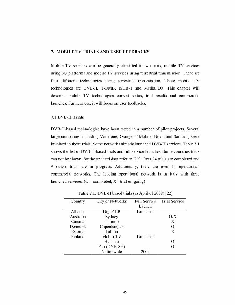
49
7. MOBILE TV TRIALS AND USER FEEDBACKS
Mobile TV services can be generally classified in two parts, mobile TV services
using 3G platforms and mobile TV services using terrestrial transmission. There are
four different technologies using terrestrial transmission. These mobile TV
technologies are DVB-H, T-DMB, ISDB-T and MediaFLO. This chapter will
describe mobile TV technologies current status, trial results and commercial
launches. Furthermore, it will focus on user feedbacks.
7.1 DVB-H Trials
DVB-H-based technologies have been tested in a number of pilot projects. Several
large companies, including Vodafone, Orange, T-Mobile, Nokia and Samsung were
involved in these trials. Some networks already launched DVB-H services. Table 7.1
shows the list of DVB-H-based trials and full service launches. Some countries trials
can not be shown, for the updated data refer to [22]. Over 24 trials are completed and
9 others trials are in progress. Additionally, there are over 14 operational,
commercial networks. The leading operational network is in Italy with three
launched services. (O = completed, X= trial on-going)
Table 7.1: DVB-H based trials (as April of 2009) [22]
Country City or Networks Full Service Launch
Trial Service
Albania DigitALB Launched Australia Sydney O/X Canada Toronto X
Denmark Copenhangen O Estonia Tallinn X
Mobili-TV Launched Helsinki O
Pau (DVB-SH) O
Finland
Nationwide 2009
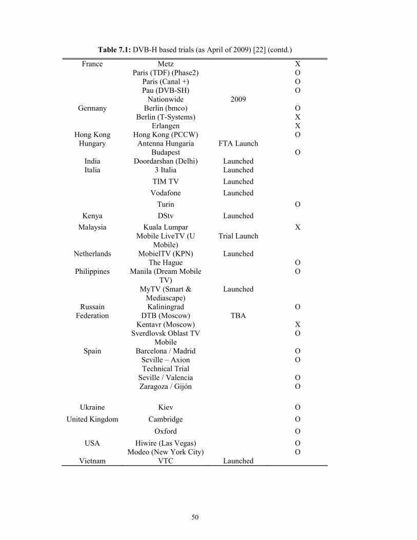
50
Table 7.1: DVB-H based trials (as April of 2009) [22] (contd.)
Metz X Paris (TDF) (Phase2) O
Paris (Canal +) O Pau (DVB-SH) O
France
Nationwide 2009 Berlin (bmco) O
Berlin (T-Systems) X Germany
Erlangen X Hong Kong Hong Kong (PCCW) O
Antenna Hungaria FTA Launch Hungary Budapest O
India Doordarshan (Delhi) Launched 3 Italia Launched
TIM TV Launched
Vodafone Launched
Italia
Turin O
Kenya DStv Launched
Kuala Lumpar X Malaysia Mobile LiveTV (U
Mobile) Trial Launch
MobielTV (KPN) Launched Netherlands The Hague O
Manila (Dream Mobile TV)
O Philippines
MyTV (Smart & Mediascape)
Launched
Kaliningrad O DTB (Moscow) TBA
Kentavr (Moscow) X
Russain Federation
Sverdlovsk Oblast TV Mobile
O
Barcelona / Madrid O Seville – Axion Technical Trial
O
Seville / Valencia O
Spain
Zaragoza / Gijón O
Ukraine Kiev O
Cambridge O United Kingdom
Oxford O
Hiwire (Las Vegas) O USA Modeo (New York City) O
Vietnam VTC Launched
51
7.2 MBMS Trials
MBMS uses the spectrum available for 3G cellular networks. UMTS mobile phones
can use the same chipset and antenna to receive MBMS services. Thus, MBMS
services can be used without deploying specific infrastructure, other than software
upgrades. Deployment of UMTS network would be cheaper, in comparison with the
cost of installing a new infrastructure for DVB-H.
There is no commercial roll-out for MBMS until now, although various trials are on-
going all over the world. Huawei and Qualcomm have completed Europe’s first trial
with Telecom Italia in Q2 of 2008. Orange and T-Mobile have conducted their trials
on TDtv, which is an extension of MBMS. TDtv basestations provided by IPWireless
have been deployed on 12 cell sites covering parts of Bristol in the UK. Also,
Orange and NextWave Network Products started trials on TDtv in 2008. TDtv uses
the universal unpaired 3G spectrum bands of 1900 MHz and 2010 MHz [23].
7.3 T-DMB Trials
The world’s first offical mobile TV service was launched in South Korea in 2005,
although trials were carried out much more earlier. After the launch of services in
Korea, Mobiles Fernsehen Deutschland (MFD) in Germany deployed T-DMB for the
FIFA World Cup 2006. Mobile TV services based on T-DMB were available in six
cities in Germany by the end of 2007. The 2008 Beijing Olympic Games was
broadcasted by four mobile TV channels using DMB technology.
One of the main advantage of T- DMB against its competitors, DVB-H and
MedialFLO, is that it has a large number of T-DMB enabled devices. These devices
are already available in the market and vary from mobile phone to vehicle devices
and usb adapters. T-DMB delivers high-quality TV programs while travelling at high
velocities.
7.4 MediaFLO Trials
MediaFLO is a unicast transmission system based on the FLO (Forward Link Only)
technology. The FLO is designed as the data transmission path which is one-way
from station to receiver.

52
Both MediaFLO and FLO were developed in the USA by Qualcomm Inc. It is
designed to provide mobile TV services and streaming video and audio. The
technology is provided as a shared resource to CDMA2000 and WCDMA operators.
Verizon Wireless is the first American carrier to launch mobile TV on the MediaFLO
network. It lauched mobile TV service in the first quarter of 2007 with offering eight
channels.
Qualcom and British Sky Broadcasting (BSkyB) announced the completion the
successfull completion of a second joint mobile TV. The second trial held in
Manchester, United Kingdom. Qualcom conducted the first trial one year before the
second trial in 2006 with BSkyB in Cambridge. The major results established from
the trial are listed below[24]:
• Users are satisfied with the video quality. MediaFLO delivered high quality
(QVGA) video streams with stereo audio at 25 fps and 240 kbit/s per video
and audio channels.
• Access time to the MediaFLO channel guide was approximately 2 seconds.
• The measured physical layer performance was better than expected.
7.5 User Feedbacks
The convergence of television and mobile technology with mobile content refers to a
new term called mobile TV. The key factor for the succes of mobile television or any
other new technology demands on the users’ interest. Users’ interests determine the
contents and undoubtedly, contents play an important role for mobile TV. This
chapter will describe the user feedbacks for mobile TV, where the results are
gathered from trials and market surveys.
It is presumed that the following reasons may affect users’ decisions for using mobile
TV and its services:
• High power consumption
• Low Quality of Service (QoS)
• High cost
• Low usability of mobile devices
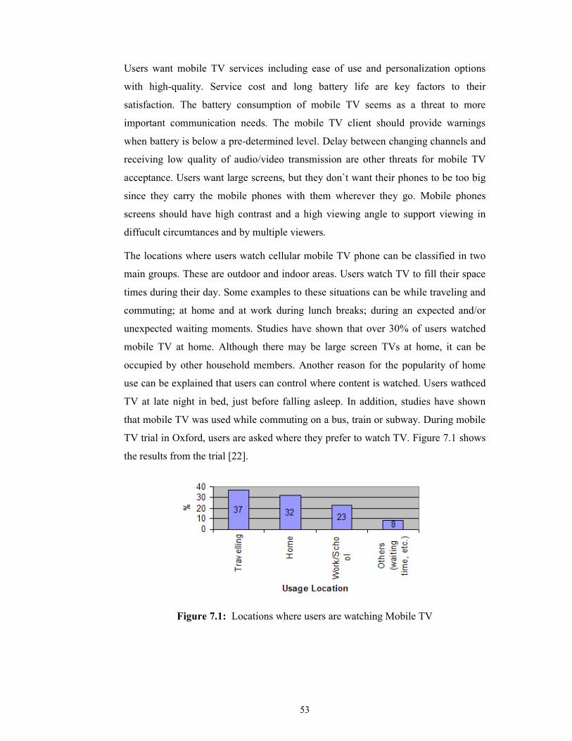
53
Users want mobile TV services including ease of use and personalization options
with high-quality. Service cost and long battery life are key factors to their
satisfaction. The battery consumption of mobile TV seems as a threat to more
important communication needs. The mobile TV client should provide warnings
when battery is below a pre-determined level. Delay between changing channels and
receiving low quality of audio/video transmission are other threats for mobile TV
acceptance. Users want large screens, but they don`t want their phones to be too big
since they carry the mobile phones with them wherever they go. Mobile phones
screens should have high contrast and a high viewing angle to support viewing in
diffucult circumtances and by multiple viewers.
The locations where users watch cellular mobile TV phone can be classified in two
main groups. These are outdoor and indoor areas. Users watch TV to fill their space
times during their day. Some examples to these situations can be while traveling and
commuting; at home and at work during lunch breaks; during an expected and/or
unexpected waiting moments. Studies have shown that over 30% of users watched
mobile TV at home. Although there may be large screen TVs at home, it can be
occupied by other household members. Another reason for the popularity of home
use can be explained that users can control where content is watched. Users wathced
TV at late night in bed, just before falling asleep. In addition, studies have shown
that mobile TV was used while commuting on a bus, train or subway. During mobile
TV trial in Oxford, users are asked where they prefer to watch TV. Figure 7.1 shows
the results from the trial [22].
Figure 7.1: Locations where users are watching Mobile TV

54
There are three prime time viewing for mobile TV according to trial results; in the
early evenings while going to home or having dinner, in the early mornings during
breakfast and while going to work and during lunchtime [25].
Success and user acceptance of new technology innovations are highly depend on the
content. It needs to be designed according to consumers’ demands. The popular
categories on mobile TV are news, soap (this category consists of soaps, series and
entertainments), sports and music. News category is the most popular one. Users do
not need to go home to watch daily news and mobile TV provides them to keep up to
date with latest news. Moreover, mobile TV provides them to watch their favourite
soap ‘anytime, anywhere’. Live broadcasts of sports are watched anytime, anywhere
if there is no conventional TV available. Music is easy to watch and mobile TV
enables users to watch and listen visual music clips. Figure 7.2 shows the usage
percentage of categories on mobile TV according to the trial that was performed in
Oxford [25].
Figure 7.2: Usage percentage of categories wathced on Mobile TV
Mobile TV can be compared with radio and traditional TV to gain perspective and
decide how content can be designed. Figure 7.3 shows some using habits for mobile
TV, radio and traditional TV [25].

55
Figure 7.3: Comparison of mobile TV, radio and traditional TV
According to the figure, users most likely to watch mobile TV for killing boredom
and less likely use it for learning new things.
As a summary, this section described the mobile TV technologies current status, trial
results and commercial launches. Users’ demands are investigated. Researchs are
performed to define in what situations, where and when the service can be used.
Moreover, Mobile TV is compared with traditional TV and radio in order to decide
the content of mobile TV services.

56

57
8. CONCLUSION AND FUTURE WORK
The main purpose for deploying third generation (3G) netwoks are to provide
enhanced voice, data and multimedia services with “anytime, anywhere, anyhow”
principle. UMTS constitutes the main standard of 3G networks and aims to provide
high-speed data with real-time video and voice calls. On the other hand, users are
expecting more capabilities from their mobile terminals. Providers are in a race to
offer innovative and interactive services to users in order to meet their demands,
since the success of new technology innovations are highly depend on the users’
acceptance. Using point-to-point architecture is not an efficient way for content
delivery and also expensive. Multicast is a better solution for delivering multimedia
services simultaneously using a shared multicast path.
In this thesis, different types of multicast technologies are investigated with their
pros and cons. New multimedia services, video streaming protocols and techniques
that are applicable to UMTS networks are presented and mobile TV is explained in
detail. The target of using streaming technologies is to connect as many users as
possible and to provide network services at lower costs and higher quality. Streaming
is made possible by high compression codecs. The list of video codecs supported by
3GPP standards and compression formats are be described.
The technology for delivering mobile TV service which we have focused on was
Multimedia Broadcast/Multicast Service (MBMS). It is proven that MBMS is a
suitable and effective technology for providing a television service to mobile
terminals over UMTS networks. Other alternatives for mobile TV such as DVB,
DMB, MediaFLO and ISDB-T are described in Chapter 6, but we consider MBMS
as the leading technology for mobile TV. Also, the mobile TV technologies current
status, trial results and commercial launches are described in Chapter 7.

58
The security related issues and their implementations are not included in this thesis;
however securing the multimedia content by applying an encryption scheme and
interoperability between different content protection standadrs are left as future
work. Spectrum allocation issues slow down the innovation and implementation of
new multicasting and mobile TV technologies. The standards organizations need to
be accelerate the proceedings for spectrum allocation for deployment of new
multicasting technologies.
As additional future works, existing compression standards can be enhanced and new
standards can be proposed for video streaming to improve the quality of video.
To summarize, it is proven that multicast has supremacy over point-to-point delivery
techniques for video streaming over 3G/UMTS networks. The mobile TV service,
which is the leading service among other multicast services, will play an important
role for the development and implementation of multicast services.

59
REFERENCES
[1] Festag, A., 2003: Mobility Support in IP Cellular Networks – A Multicast-Based Approach, PhD Thesis, Technischen Universität Berlin, Berlin
[2] Diot, C., Levine, B.N., Lyles, B., Kassem, H., and Balensiefen, D., 2002: Deployment issues for the IP multicast service and architecture, Proceedings of IEEE Communication Networks/Systems, Vol. 14, pp. 78-88.
[3] Iwacz, G., Jajszczyk, A., and Zajączkowski, M., 2008: Multimedia Broadcasting and Multicasting in Mobile Networks, John Wiley & Sons, Ltd. Publication, pp. 5 - 21.
[4] Xylomenos, G., Vogkas, V., and Thanos, G., 2006: The multimedia broadcast/multicast service, Wireless Communications & Mobile
Computing Academic Journal, Vol. 8, Issue 2, pp. 255 – 265.
[5] 3GPP TS 22.146 V9.0.0, 2008: Multimedia Broadcast/Multicast Service; Stage 1 (Release 9), 2008-06.
[6] 3GPP TS 23.246 V7.4.0, 2007: Universal Mobile Telecommunications System (UMTS); Multimedia Broadcast/Multicast Service (MBMS); Architecture and functional description; Release 7, 2007-10.
[7] 3GPP TS 25.346 V8.3.0, 2009: Universal Mobile Telecommunications System (UMTS); Introduction of the Multimedia Broadcast/Multicast Service (MBMS) in the Radio Access Network (RAN); Stage 2; Release 8, 2009-04.
[8] 3GPP TR 25.922 V7.1.0, 2007: Universal Mobile Telecommunications System
(UMTS); Radio resource management strategies; Release 7, 2007-03.
[9] Alexiou, A., Bouras, C., and Rekkas, E., 2008: Efficient delivery of MBMS multicast traffic over HSDPA, Proceedings of IEEE Symposium on Computers and Communications (ISCC 2008), pp. 50-55.
[10] 3GPP TR 25.803 V6.0.0, 2005: 3rd Generation Partnership Project; Technical Specification Group Radio Access Network; S-CCPCH performance for MBMS; (Release 6), 2005-09
[11] Fuyong, Y., 2007: “MBMS Basic Principle” , Huawei UMTS Marketing Execution Department, July 2007.
[12] 3GPP TS 22.246 V8.5.0, 2008: Multimedia Broadcast/Multicast Service (MBMS) user services; Stage 1(Release 8), 2008-03.
[13] 3GPP TS 26.346 V7.9.0, 2008: Universal Mobile Telecommunications System (UMTS); Multimedia Broadcast/Multicast Service (MBMS); Protocols and codecs, Release 7, 2008-10.

60
[14] 3GPP TR 26.902 V7.1.2, 2008: Digital cellular telecommunications system (Phase 2+); Universal Mobile Telecommunications System (UMTS); Video codec performance, Release 7, 2008-01.
[15] 3GPP TS 26.236 V8.0.0, 2009: Universal Mobile Telecommunications System (UMTS); LTE; Packet switched conversational multimedia applications; Transport protocols, Release 8, 2009-01.
[16] Ahmad, A., and Ibrahim, I.,K., 2008: Multimedia Transcoding in Mobile and Wireless Networks, Information Science Reference, pp. 31 – 46.
[17] DVB Document A098, 2005: IP Datacast over DVB-H: Architecture, Proceedings of Digital Video Broadcasting Document, November 2005
[18] Rümmer, R., Gluhak, A, and Aghvami, A., H., 2009: Multicast in Third-Generation Mobile Networks: Services, Mechanisms and Performance, John Wiley & Sons, Ltd. Publication, pp. 221 – 236.
[19] MediaFLO, 2009: FLO Technology Overview Brochure, Qualcomm Incorpotated. <http://www.mediaflo.com>, accessed at 10.03.2009.
[20] ETSI EN 300401, 2006: Radio Broadcasting Systems; Digital Audio Broadcasting (DAB) to mobile, portable and fixed receivers, V1.4.1 January 2006.
[21] Kumar, A., 2007: Mobile TV: DVB-H, DMB, 3G Systems and Rich Media Applications, Focal Press, pp. 311 – 331.
[22] DVB-H Project, DVB-H Services, <http://www.dvb-h.org/services.htm>, accessed at 24.03.2009 .
[23] IPWireless, 3UK, Orange, Telefonica and Vodafone Trial Mobile TV powered
by TDtv Technology, accessed at 08.04.2009.
<http://www.ipwireless.com/news/2006archive/press101106>
[24] MediaFLO whitepaper, Technology Comparison: MediaFLO and DVB-H,
<http://www.qualcomm.com/common/documents/white_papers/MF_WP_FLOvsDVBH.pdf>, accessed at 20.04.2009.
[25] Mason, S., 2006: Mobile TV- results from the DVB-H trial in Oxford. EBU Technical Review.

61
CURRICULUM VITAE
Gözde ERGÜL was born in Amasya, in 1984. She completed her higher education in Istanbul Maltepe Anatolian High School. She received her Bachelor of Science degree from Yıldız Technical University, Electronics and Communication Engineering with 5th honours degree in 2006. Same year, she attended to Istanbul Technical University Telecommunications Engineering Master’s (MSc) Programme. She has been working as a software validation engineer in Nortel Netas in Multimedia Communications department since 2006.