stalkerbot - machine intelligence lab · pdf file · 2003-04-23the stalkerbot...
TRANSCRIPT
StalkerBot
Karl Dockendorf
EEL5666C
Intelligent Machine Design Laboratory
TAs: Jason Plew, Uriel Rodriguez
Instructor: A. A. Arroyo

2
TTAABBLLEE OOFF CCOONNTTEENNTTSS
Abstract 3
Executive Summary 4
Introduction 5
Integrated System 5
Mobile Platform 6
Actuation 7
Sensors 8
Behaviors 15
Experimental Layout and Results 16
Conclusion 18
Documentation 19
Appendices 20

3
AABBSSTTRRAACCTT The StalkerBot is an autonomous mobile robot that exhibits behaviors of an animal stalking prey. The robot is based on infrared sensors, bump detection switches, a digital compass, a photoreflector, a CMU-Cam, and radio frequency data transmission. These sensors would be incorporated together to allow the robot to track moving objects and calculate their relative position. However, the photoreflector was damaged and unable to be replaced. While the StalkerBot is not following its prey, it remains still waiting for an object to move. An Atmel ATmega103 microcontroller controls the robot motion and behavior. The ATmega103 header board is tested and functional, as are the sensors. The entire robot has been integrated to satisfaction (aside from the photoreflector).

4
EEXXEECCUUTTIIVVEE SSUUMMMMAARRYY
The StalkerBot project encompasses multiple difficulties. There are many sensors
integrated into the project as are there behaviors. The sensors employed include bump
switches, infrared rangers, digital compass, photoreflector, CMUcam, and radio
frequency communication modules. Each sensor plays a unique role. The most critical
of which is the CMUcam module that provides “vision” for the robot. In addition, the RF
communication hardware provides a link for data transfer.
The behaviors the StalkerBot can exhibit are unique to several of these sensors.
The ability to navigate with a digital compass provides extra functionality to the robot.
The CMUcam provides imaging capabilities to the robot. The camera module furnishes
statistical data on image windows such as mean and standard deviation. These values can
be used to detect image disturbances (i.e. movement).
Recognizing moving objects and tracking them is a primary mission of this
project, along with navigation. The synthesis of the sensors and behaviors allows the
StalkerBot to perform its specified objectives.

5
IINNTTRROODDUUCCTTIIOONN
The StalkerBot mobile autonomous robot is developed to track moving objects.
For this to work, the StalkerBot must identify a change in its surroundings then pursue
this disturbance. Aside from this functionality, the StalkerBot will calculate its distance
and bearing along with that of the target in reference from StalkerBot’s starting position.
This document provides detailed information on the sensors, behavior, mobile
platform, and movement of the StalkerBot. Each section contains detailed information
regard the operation of the component and its integration into the robot.
IINNTTEEGGRRAATTEEDD SSYYSSTTEEMM
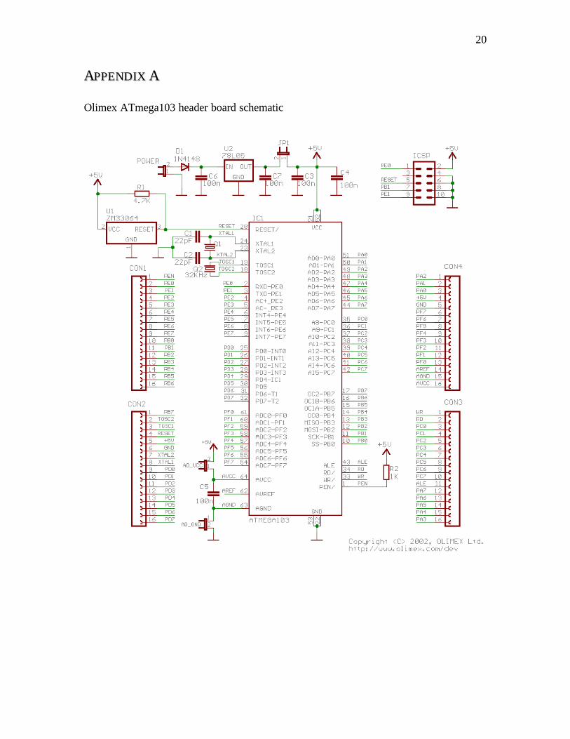
The StalkerBot is based on the Atmel ATmega103 microcontroller. The
microcontroller comes as part of the Olimex ATmega103 header board (See Figure
##########). The header board is attached to the sensors via wirewrap and soldering on
a perf-board. The robot is based on infrared sensors, bump detection switches, a digital
compass, a photoreflector, and a CMU-Cam. In addition, the StalkerBot contains an
onboard radio frequency (433.92 MHz) transmitter. The StalkerBot is intended to exhibit
behaviors of an animal stalking prey.

6
Figure 1: Block Diagram
Each sensor type is integrated into robot to gather a particular piece of data. The
bump switches provide the robot with a means to detect collisions. The infrared ranging
modules detect objects before the robot collides with the object. The compass module
and photoreflector generate information regarding speed and trajectory. The CMUcam is
the most crucial sensor to the behavior of the robot; the camera processes images and can
track “blobs” of color.
MMOOBBIILLEE PPLLAATTFFOORRMM
The platform design for the StalkerBot is based on a toy radio controlled car.
This platform was chosen for several reasons. First, the toy car platform is relatively
sturdy (as compared with an airplane wood platform). Second, the toy car comes with

7
motors which can drive the car forward at significant speed. Quick pursuit is one of the
design goals.
The RC car has been modified to fit a new steering servo. The original steering
servo was removed and a standard servo was used to replace it. Additional grooves and
slots were cut into the body of the radio controlled car. The remainder of the steering
system was left unchanged.
The finished product has produced a toy car which has been overloaded with
instrumentation and batteries. Thus, the RC car has been weighted down and moves
significantly slower than originally planned. Weight has had a dramatic impact on
acceleration.
The original RC car was purchased at Toys ‘R’ Us in Gainesville, FL on February
9, 2003. The radio controller car (‘Super Tret’) was manufactured by FastLane R/C, Inc.
AACCTTUUAATTIIOONN
The actuation of the robot platform is the same as a radio controlled car. The car
is able to turn the front wheels left and right to steer. A high-speed motor drives the car
forward and backward. Actuation is controlled by the behavior algorithms detailed later
in this report.
A standard servo is used to control steering. The MX-400 servo is distributed by
Maxx Products, Inc. and resold through Acroname, Inc. (4894 Sterling Drive, Boulder
CO, 80301-2350, phone: 720-564-0373) via their website (http://www.acroname.com).
The servo specifications are in the table below.

8
Size LxHxW (in)
Weight (oz) Torque (in-oz.) Speed (sec / 60 degrees)
Ball Bearing
1.60x0.79x1.50 1.66 44 0.15 Oilite
The DC motor, which drives the RC car in forward and reverse, is unknown. This
motor is optoisolated from the microcontroller board. The isolated signals are used to
activate pins on the original RC car controller board.
SSEENNSSOORRSS
The StalkerBot operates based on information gathered by its sensors. Bump
sensors, infrared sensors, a digital compass, a photoreflector, and a CMU-Cam provide
the information required.
Bump Sensors
Bump switches are used to detect when the robot bumps into an object. The
bump sensors are mounted around the outside of the robot. The triggering of these
sensors indicates contact with an object. These sensors are simple switches which are
polled by the microprocessor before it evaluates its behavior.
Infrared Sensors
IR range finders provide approximate distance to target values. Two of these
components will be mounted on the front of the robot. The devices being used are Sharp
GP2D12 infrared rangers. These components were purchased from Acroname, Inc.
(4894 Sterling Drive, Boulder CO, 80301-2350, phone: 720-564-0373) via their website
(http://www.acroname.com).

9
Figure 2: Sharp GP2D12 photo
Figure 3: Sharp GP2D12 details
The infrared rangers are also polled before each evaluation of the robot’s
behavior. These components act as an early warning system for collision detection.
Digital Compass
The compass provides bearing information. Along with the speed measurements,
this device enables crude calculation of relative position. The device being employed is
the Devantech CMPS03 magnetic compass module. The vendor for this compass is

10
Acroname, Inc. (4894 Sterling Drive, Boulder CO, 80301-2350, phone: 720-564-0373);
the purchase was made via their website (http://www.acroname.com).
Figure 4: Devantech CMPS03 photo
Figure 5: Devantech CMPS03 details

11
Figure ####: Devantech circuit design
Photoreflector
The photoreflector is used in conjunction with a white and black disc attached to
the rear axle of the robot. This setup generates a shaft encoder. The pulses of the
photoreflector are counted, which over time provide speed data. The photoreflector
incorporated is the Hamamastu P5587 photoreflector. The vendor for this photoreflector
is Acroname, Inc. (4894 Sterling Drive, Boulder CO, 80301-2350, phone: 720-564-
0373); the purchase was made via their website (http://www.acroname.com).
Figure 6: Hamamatsu P5587 photo
12
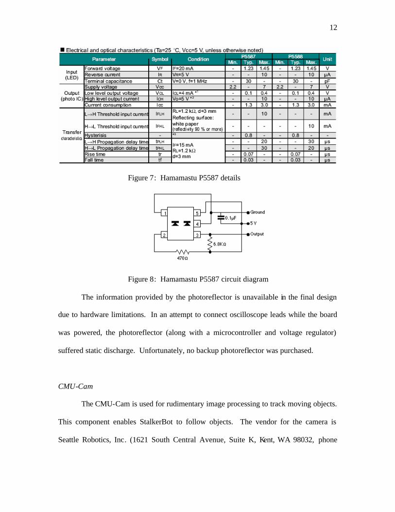
Figure 7: Hamamastu P5587 details
Figure 8: Hamamastu P5587 circuit diagram
The information provided by the photoreflector is unavailable in the final design
due to hardware limitations. In an attempt to connect oscilloscope leads while the board
was powered, the photoreflector (along with a microcontroller and voltage regulator)
suffered static discharge. Unfortunately, no backup photoreflector was purchased.
CMU-Cam
The CMU-Cam is used for rudimentary image processing to track moving objects.
This component enables StalkerBot to follow objects. The vendor for the camera is
Seattle Robotics, Inc. (1621 South Central Avenue, Suite K, Kent, WA 98032, phone

13
253-630-9836); the purchase was made via their website
(http://www.seattlerobotics.com).
Figure 9: CMUcam photo
(See also schematic in Appendix B.)
The CMUcam is imployed for its GM (Get Mean) and TW (Track Window)
functions. The first, GM, returns the RGB color averages; when there is a dramatic
change in the averages, there must be movement in the image. Based on whether or not
movement is detected, the TW function is called. The TW function tracks the average
color of the center frame of the camera.

14
RF Transmitter / Receiver
The RF transmitter and receiver modules provide a communications link to a base
station. The base station will receive navigational data from the mobile robot. The
devices being employed are the Reynolds Electronics TWS-434A and RWS-434 433.92
MHz radio frequency transmitter and reciever. The vendor for these components is
Reynolds Electronics (3101 Eastridge Lane Canon City, Co. 81212; Voice: (719) 269-
3469; Fax: (719) 276-2853) the purchase was made via their website
(http://www.rentron.com).
Figure #####: TWS-434A and RWS-434
15
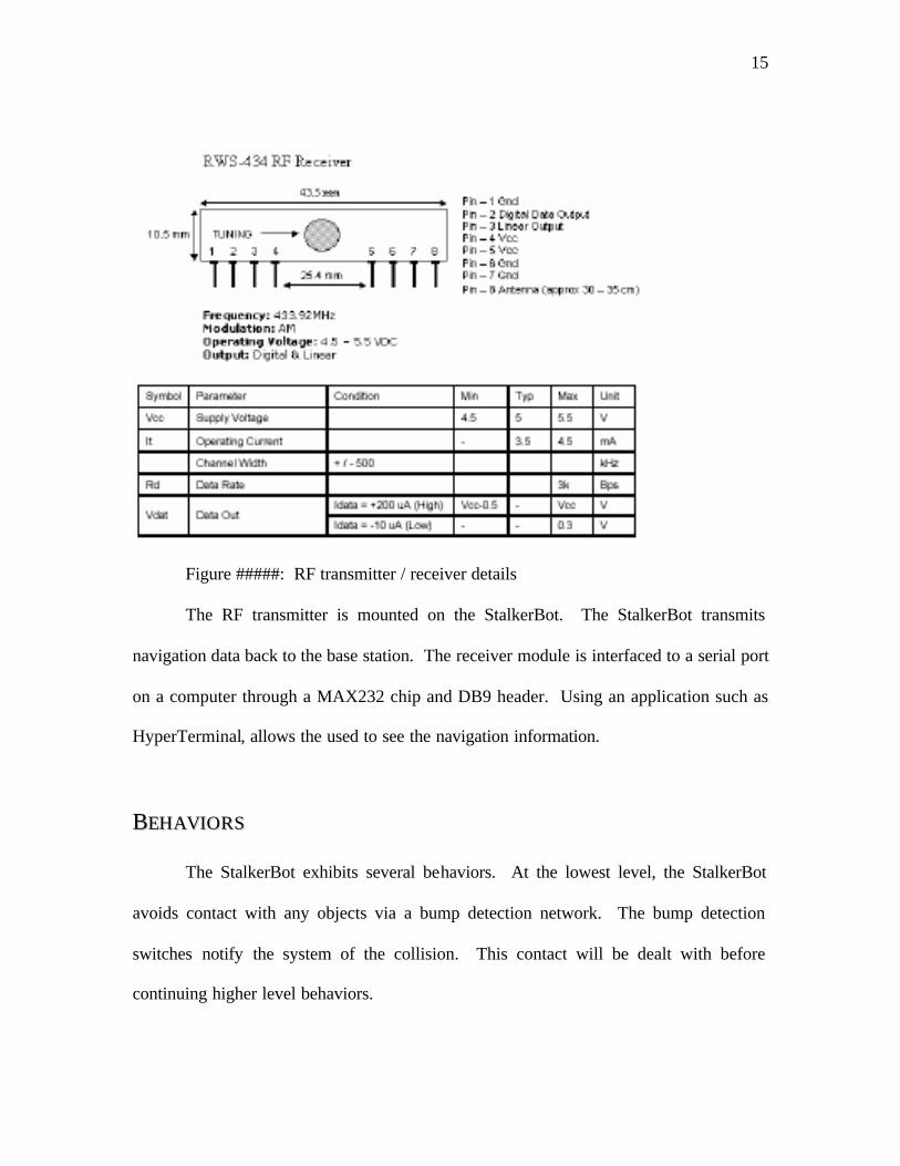
Figure #####: RF transmitter / receiver details
The RF transmitter is mounted on the StalkerBot. The StalkerBot transmits
navigation data back to the base station. The receiver module is interfaced to a serial port
on a computer through a MAX232 chip and DB9 header. Using an application such as
HyperTerminal, allows the used to see the navigation information.
BBEEHHAAVVIIOORRSS
The StalkerBot exhibits several behaviors. At the lowest level, the StalkerBot
avoids contact with any objects via a bump detection network. The bump detection
switches notify the system of the collision. This contact will be dealt with before
continuing higher level behaviors.

16
The StalkerBot also attempts to avoid collisions before they happen by detecting
approaching objects with infrared rangers. The IR rangers are set to only take action if
the objects are very close.
The StalkerBot’s higher level behaviors included waiting and stalking. While
waiting, the robot will scan for movement in front of him. If movement is detected, the
robot enters into a stalking state. The stalking state is marked by the pursuit of an object.
The StalkerBot will pursue the same object until it stops or the tracking is lost. If the
object attempts to remain still, the StalkerBot will ram it a few times before leaving it
alone.
EEXXPPEERRIIMMEENNTTAALL LLAAYYOOUUTT AANNDD RREESSUULLTTSS
Experimentation began with the testing of the Atmel ATmega103 microcontroller.
The board is required to be powered minimally by 7V. After powering the header board
(See Figure 1), the I/O ports drove LEDs demonstrating the functional state of the board.
The onboard regulator provides at most 100 mA, thus additional regulators are used for
the other components.

17
Figure 1: Olimex ATmega103 header board
Below is a chart of progress of component integration:
Components Testing Interfaced
Bump Switches Complete Complete
Infrared Rangers Complete Complete
Photoreflector Complete Complete / Destroyed
Compass Complete Complete
Camera Complete Complete
Radio Frequency Transmitter / Receiver
Complete Complete
I learned that oscilloscope leads should be attached while power is disconnected.
While interfacing the photoreflector with the microcontroller, the oscilloscope was
attached to help debug problems. However, a spark arced across from a Vcc pin to the
oscilloscope input lead. This not only ruined the photoreflector, but also ruined the
voltage regulator and the microcontroller.
18
After the voltage regulator and microcontroller were replaced, the final project
was finished without a photoreflector (a replacement was not available). All other
objectives were achieved.
Although the robot was originally intended to be programmed in assembly, the
final software is written in C code.
CCOONNCCLLUUSSIIOONN
The ATmega103 microcontroller has been tested and found to be functional. The
sensors have been tested to a sufficient degree. All sensors were then interfaced with
processor. Most design goals were achieved with the possible exclusion of those based
on the photoreflector.
In beginning this project anew, I would have started programming in C instead of
assembly. In addition, I would not have put as many sensors into the project as I did. I
would have concentrated more fully on the functional behavior of the interface with the
CMUcam. Better processor selection would also be important; having the right port for
each type of sensor makes interfacing then significantly easier.
Due to unforeseen destruction of the photoreflector, the possibilities of relative
navigation could not be explored. If a part is cheap, one should always buy a backup or
replacement with the original purchase.

19
DDOOCCUUMMEENNTTAATTIIOONN
Arroyo, A.A.
Olimex, Ltd. http://www.olimex.com/dev/images/avr-h103b-sch.gif, 2002. Header board
schematic for Atmel ATmega103.
Plew, Jason. Assistance with optoisolators. 2003.
Rathinasamy, Palani. Servo controlling code. 2003.
Rodriguez, Uriel. Assistance with power problems. 2003.
Tripican, Kyle. CMU camera code. 2003.
20
AAPPPPEENNDDIIXX AA
Olimex ATmega103 header board schematic

21
AAPPPPEENNDDIIXX BB
CMU-cam schematic

22
AAPPPPEENNDDIIXX CC
#include <io.h> #include <sig-avr.h> #include <stdlib.h> #include <interrupt.h> //#include <progmem.h> #include <string-avr.h> typedef unsigned char u08; typedef unsigned int u8; typedef char s08; typedef unsigned short u16; typedef short s16; volatile u8 recvtemp; volatile u8 recvi=0; volatile u8 cmudat[20]; #define FORWARD 0x04 #define BACKWARD 0x08 #define STOP 0x00 #define LEFT 0x50 #define RIGHT 0x24 #define CENTER 0x3D u16 risingedge; volatile u16 compasswidth; #define MAXTICKS 0x64 u8 clockticks; volatile u8 clockreset; u8 currspeed; volatile u8 lastspeed; u8 currlevel; #define RFBITTIME 39 #define SIGBUFFSIZE 0x40 volatile u08 RFsignal[SIGBUFFSIZE]; volatile int rfindex; volatile u8 rfbitnum; void move(u8 mask){ u8 gg = 0xF3 & inp(PORTE); outp(mask | gg, PORTE); } void turn(u8 pwmvalue){ outp(pwmvalue, OCR2); } void initports(void) { outp(0xC0,DDRB); outp(0x00,DDRD);

23
outp(0x0E,DDRE); } void initmotors(void) { outp(0x6B, TCCR2); turn(CENTER); } //Initialize UART //'baud' is the baud register divider void inituart(void) { /* Set baud rate */ outp(0x98, UCR); outp(0x09, UBRR); /* Enable Receiver and Transmitter */ // 1 stop bit } //Send a single byte of data //'data' is the byte sent void uarttransmit(unsigned char data) { /* Wait for empty transmit buffer */ while (!(USR & (1<<UDRE))){} /* Put data into buffer, sends the data */ outp(data,UDR); } //Send a given EOS terminated string void uartstring(unsigned char * myStringIn) { unsigned char *myString = myStringIn; unsigned char ch1; unsigned char gotNULL = 0; // ch1= *myString++; while(!gotNULL){ // uarttransmit(ch1); ch1 = *myString++; if(ch1 == '\r'){ gotNULL = 1; } uarttransmit(ch1); // } } } void delay(u16 time){ do{ u08 i=10; do{ asm volatile("nop\n\t" "nop\n\t"

24
"nop\n\t" "nop\n\t" ::); }while(--i); }while(--time); } void rfstring(unsigned char * myStringIn) { u8 length = 0; while (rfindex != -1) {} while ((myStringIn[length] != '\r') && (length < 49)) { RFsignal[length] = myStringIn[length]; length++; } outp(length, PORTC); RFsignal[length] = '\r'; rfbitnum = 0; rfindex = 0; } SIGNAL(SIG_UART_RECV){ recvtemp=inp(UDR); if(recvtemp != 0x3A){ if(recvtemp == 0x20 || recvi==9){ //9 recvi=0; } else if(recvi==0){ if(recvtemp == 0xFF){ cmudat[recvi]=recvtemp; recvi++; } } else if(recvtemp !=0x20 && recvi<9){ //9 cmudat[recvi]=recvtemp; recvi++; } } } SIGNAL(SIG_INPUT_CAPTURE1){ if(TCCR1B & (1<<ICES1)) risingedge = ICR1; else compasswidth = ICR1 - risingedge; outp(TCCR1B ^ (1<<ICES1), TCCR1B); } SIGNAL(SIG_OUTPUT_COMPARE1B){ u16 rftemp2 = OCR1B+RFBITTIME; u8 rftemp; OCR1B = rftemp2; if(rfindex == -1) { rftemp = inp(TCCR1A) | (1<<COM1B0); outp(rftemp, TCCR1A); } else { if(rfbitnum == 0) {

25
rftemp = inp(TCCR1A) & ~(1<<COM1B0); outp(rftemp, TCCR1A); rfbitnum++; } else if (rfbitnum > 8) { rftemp = inp(TCCR1A) | (1<<COM1B0); outp(rftemp, TCCR1A); rfbitnum++; if (rfbitnum > 9) { rfbitnum = 0; if (RFsignal[rfindex] == '\r') rfindex = -1; else rfindex++; } } else { if (RFsignal[rfindex] & (1<<(rfbitnum-1))) { rftemp = inp(TCCR1A) | (1<<COM1B0); outp(rftemp, TCCR1A); } else { rftemp = inp(TCCR1A) & ~(1<<COM1B0); outp(rftemp, TCCR1A); } rfbitnum++; } } } SIGNAL(SIG_OUTPUT_COMPARE0){ clockticks = clockticks + 1; if (clockticks == MAXTICKS) { clockreset = 1; clockticks = 0; lastspeed = currspeed; } u8 nowlevel = inp(PORTD) & (1<<PD5); if(nowlevel ^ currlevel) { currlevel = nowlevel; currspeed = currspeed + 1; } } void blink(void){ uartstring("L1 1\r"); delay(1500); delay(1500); delay(15000); uartstring("L1 0\r"); delay(15000); delay(1500); delay(1500); } void blink2(void){ u08 junk[10] = ""; junk[0] = 'L'; junk[1] = '1';
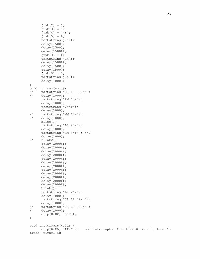
26
junk[2] = 1; junk[3] = 1; junk[4] = '\r'; junk[5] = 0; uartstring(junk); delay(1500); delay(1500); delay(15000); junk[3] = 0; uartstring(junk); delay(15000); delay(1500); delay(1500); junk[3] = 2; uartstring(junk); delay(1000); } void initcam(void){ // uartstring("CR 18 44\r"); // delay(1000); uartstring("PM 0\r"); delay(1000); uartstring("SW\r"); delay(1000); // uartstring("MM 1\r"); // delay(1000); blink(); uartstring("L1 2\r"); delay(1000); uartstring("RM 3\r"); //7 delay(1000); // blink2(); delay(20000); delay(20000); delay(20000); delay(20000); delay(20000); delay(20000); delay(20000); delay(20000); delay(20000); delay(20000); delay(20000); delay(20000); blink(); uartstring("L1 2\r"); delay(1000); uartstring("CR 19 32\r"); delay(1000); // uartstring("CR 18 40\r"); // delay(1000); outp(0x0F, PORTC); } void inittimers(void) { outp(0x2A, TIMSK); // interrupts for timer0 match, timer1b match, timer1 ic

27
outp(0x20, TCCR1A); outp(0xC3, TCCR1B); outp(0x08, ASSR); outp(0x09, TCCR0); // outp(0x20, OCR0); // every 1.007 ms clockticks = 0; clockreset = 0; currspeed = 0; lastspeed = 0; currlevel = 0; rfindex = -1; rfstring("INIT\r"); } u16 adcsample(u8 pinnum) { u16 result; outp(pinnum, ADMUX); outp(0xC6, ADCSR); while(!(ADCSR & (1<<ADIF))) {} result = ADCW; sbi(ADCSR,ADIF); outp(0xC6, ADCSR); while(!(ADCSR & (1<<ADIF))) {} result = ADCW; sbi(ADCSR,ADIF); return(result); } void avoid_behavior(void){ u8 bump = inp(PORTE) & 0xF0; u8 rightir = (u8)(adcsample(0x00)>>2); u8 leftir = (u8)(adcsample(0x01)>>2); if (leftir < 40 && rightir < 40){ move(FORWARD); turn(CENTER); } else if (leftir > 40 && rightir < 40){ if (leftir > 60) { move(BACKWARD); turn(LEFT); } else { move(FORWARD); turn(RIGHT); } } else if (leftir < 40 && rightir > 40){ if (rightir > 60) { move(BACKWARD); turn(RIGHT); } else { move(FORWARD); turn(LEFT); } } else { move(BACKWARD); turn(CENTER); } }

28
u8 current_state, next_state, statecounter, delaycounter; u8 rmax, rmin, gmax, gmin, bmax, bmin; u8 minx, midx, maxx, miny, midy, maxy; u8 lastleftir, lastrightir, toleranceir, colortol; u16 lastr, lastg, lastb; u8 check_bump(void) { u8 bump = (inp(PINE) & 0xF0)>>4; switch(bump) { case 0: return 0; case 1: turn(RIGHT); move(BACKWARD); break; case 2: turn(CENTER); move(BACKWARD); break; case 4: turn(LEFT); move(BACKWARD); break; case 8: turn(CENTER); move(FORWARD); break; default: turn(CENTER); move(STOP); break; } return 1; } u8 lastlir, lastrir; int check_ir(void){ u8 rightir = (u8)(adcsample(0x00)>>2); u8 leftir = (u8)(adcsample(0x01)>>2); lastlir = (lastlir + leftir)>>1; lastrir = (lastrir + rightir)>>1; if (lastlir <= 100 && lastrir <= 100){ return 0; } else if (lastlir > 100 && lastrir < 100){ if (lastlir > 110) { move(BACKWARD); turn(LEFT); } else { return 0; } } else if (lastlir < 100 && lastrir > 100){ if (lastrir > 110) { move(BACKWARD); turn(RIGHT); } else { return 0; }

29
} else { move(BACKWARD); turn(CENTER); } return 1; } void chase_behavior(void) { u16 currr, currg, currb; u8 conf, numpix; // u08 uartstr[20] = ""; if (check_bump()){ delaycounter = 2 + (inp(TCNT1L) & 0x03); return; } if (check_ir()){ delaycounter = 2 + (inp(TCNT1L) & 0x01); return; } if (delaycounter) { delaycounter--; return; } switch (current_state) { case 0: move(STOP); turn(CENTER); outp(0x00, PORTC); next_state = 1; break; case 1: move(STOP); turn(CENTER); uartstring("SW 30 54 50 90\r"); // uartstring("SW 30 60 50 110\r"); next_state = 2; break; case 2: move(STOP); turn(CENTER); next_state = 3; break; case 3: move(STOP); turn(CENTER); uartstring("GM\r"); // outp(cmudat[2], PORTC); next_state = 4; break;

30
case 4: move(STOP); turn(CENTER); next_state = 5; break; case 5: // rmin = cmudat[2] - (cmudat[5]>>1); // rmax = cmudat[2] + (cmudat[5]>>1); // gmin = cmudat[3] - (cmudat[6]>>1); // gmax = cmudat[3] + (cmudat[6]>>1); // bmin = cmudat[4] - (cmudat[7]>>1); // bmax = cmudat[4] + (cmudat[7]>>1); lastr = (u16)cmudat[2]; lastg = (u16)cmudat[3]; lastb = (u16)cmudat[4]; // outp(0xFF, PORTC); next_state = 6; break; case 6: turn(CENTER); move(STOP); currr = (u16)cmudat[2]; currg = (u16)cmudat[3]; currb = (u16)cmudat[4]; lastr = (lastr + currr)>>1; lastg = (lastg + currg)>>1; lastb = (lastb + currb)>>1; if ((((lastr - currr) > colortol) || ((currr - lastr) > colortol)) && (((lastg - currg) > colortol) || ((currg - lastg) > colortol)) && (((lastb - currb) > colortol) || ((currb - lastb) > colortol))) { outp(0xF0, PORTC); next_state = 7; } else { outp(0x0F, PORTC); next_state = 6; } break; case 7: uartstring("\r"); next_state = 8; break; case 8: next_state = 9; break; case 9: uartstring("TW\r"); next_state = 10; break;

31
case 10: move(STOP); next_state = 11; break; case 11: minx = cmudat[2]; miny = cmudat[3]; maxx = cmudat[4]; maxy = cmudat[5]; numpix = cmudat[6]; conf = cmudat[7]; midx = (minx+maxx)>>1; midy = (miny+maxy)>>1; if (conf > 50){ statecounter = 0; if(midx < 25) { turn(LEFT); } else if (midx > 55) { turn(RIGHT); } else { turn(CENTER); } if(numpix < 60) { move(FORWARD); } else if (numpix > 100) { move(BACKWARD); } else { move(STOP); } } else { statecounter++; } outp(numpix, PORTC); if (statecounter > 20) { statecounter = 0; next_state = 0; } else { next_state = 12; } break; case 12: next_state = 11; break; default: move(STOP); turn(CENTER); next_state = 0; break; } current_state = next_state; }
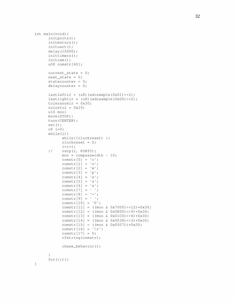
32
int main(void){ initports(); initmotors(); inituart(); delay(10000); inittimers(); initcam(); u08 comstr[40]; current_state = 0; next_state = 0; statecounter = 0; delaycounter = 0; lastleftir = (u8)(adcsample(0x01)>>2); lastrightir = (u8)(adcsample(0x00)>>2); toleranceir = 0x30; colortol = 0x19; u16 moo; move(STOP); turn(CENTER); sei(); u8 i=0; while(1){ while(!clockreset) {} clockreset = 0; i=i+1; // outp(i, PORTC); moo = compasswidth - 10; comstr[0] = 'c'; comstr[1] = 'o'; comstr[2] = 'm'; comstr[3] = 'p'; comstr[4] = 'a'; comstr[5] = 's'; comstr[6] = 's'; comstr[7] = ' '; comstr[8] = '='; comstr[9] = ' '; comstr[10] = '0'; comstr[11] = ((moo & 0x7000)>>12)+0x30; comstr[12] = ((moo & 0x0E00)>>9)+0x30; comstr[13] = ((moo & 0x01C0)>>6)+0x30; comstr[14] = ((moo & 0x0038)>>3)+0x30; comstr[15] = ((moo & 0x0007))+0x30; comstr[16] = '\r'; comstr[17] = 0; rfstring(comstr); chase_behavior(); } for(;;){} }