stainless steel pneumatic cylinders - fluidtechnik bohemia, s.r.o
TRANSCRIPT
�
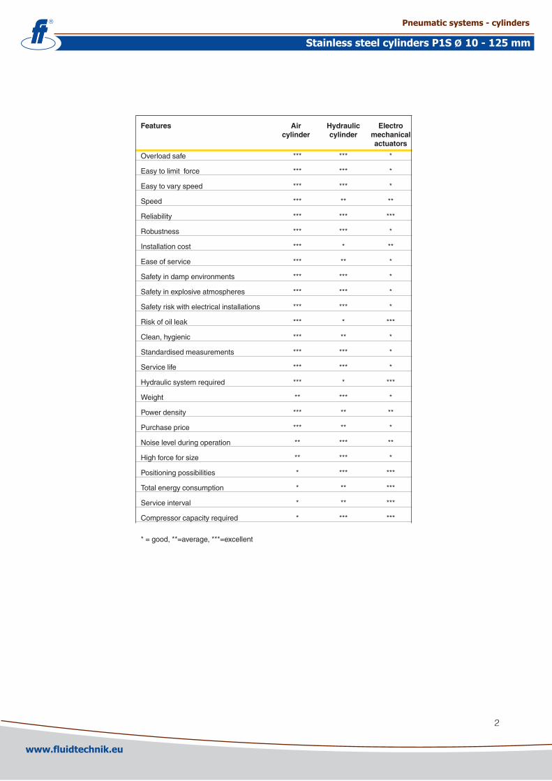
Features Air Hydraulic Electro cylinder cylinder mechanical actuators
Overload safe *** *** *
Easy to limit force *** *** *
Easy to vary speed *** *** *
Speed *** ** **
Reliability *** *** ***
Robustness *** *** *
Installation cost *** * **
Ease of service *** ** *
Safety in damp environments *** *** *
Safety in explosive atmospheres *** *** *
Safety risk with electrical installations *** *** *
Risk of oil leak *** * ***
Clean, hygienic *** ** *
Standardised measurements *** *** *
Service life *** *** *
Hydraulic system required *** * ***
Weight ** *** *
Power density *** ** **
Purchase price *** ** *
Noise level during operation ** *** **
High force for size ** *** *
Positioning possibilities * *** ***
Total energy consumption * ** ***
Service interval * ** ***
Compressor capacity required * *** ***
* = good, **=average, ***=excellent
www.fluidtechnik.euwww.fluidtechnik.eu
Pneumatic systems - cylindersPneumatic systems - cylinders
Stainless steel cylinders P1S 10 - 125 mmStainless steel cylinders P1S 10 - 125 mmØØ

3
Contents PageStainlesssteelcylinders,generalinformation................................................4Guideforselectingsuitabletubing................................................................6P1S-S,ISO643�,Ø10-Ø�5............................................................................8
Maindata....................................................................................................8Cylinderforces...........................................................................................8Cushioningdiagram...................................................................................9Materialspecification.................................................................................9Strokelength............................................................................................10Orderkey..................................................................................................10Dimensions...............................................................................................11Mountings............................................................................................1�-13
P1S-ISO6431,Ø3�-Ø1�5...........................................................................14Maindata..................................................................................................14Cylinderforces.........................................................................................14Cushioningdiagram.................................................................................14Strokelength............................................................................................15Orderkey..................................................................................................15DimensionsØ3�-Ø63...............................................................................16MaterialspecificationØ3�-Ø63................................................................16DimensionsØ80-Ø1�5.............................................................................17MaterialspecificationØ80-Ø1�5..............................................................17Mountings............................................................................................18-�1
Sensors....................................................................................................��-�5Connectingcableswithoneconnector........................................................�6Maleconnectorsforconnectingcables.......................................................�6Readytouseconnectingcableswithconnectorsateachend...................�6ConnectionblockValvetronic110................................................................�7SealkitsforP1Scylinders............................................................................�8Grease..........................................................................................................�8
www.fluidtechnik.euwww.fluidtechnik.eu
Pneumatic systems - cylindersPneumatic systems - cylinders
Stainless steel cylinders P1S 10 - 125 mmStainless steel cylinders P1S 10 - 125 mmØØ
4
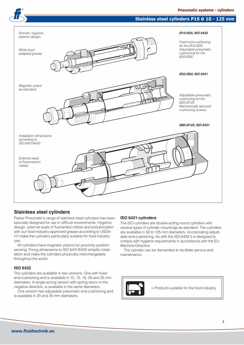
Smooth, hygienic exterior design.
Ø80-Ø125, ISO 6431
Fixed end-cushioning for the Ø10-Ø25. Adjustable pneumatic cushioning for the Ø20-Ø25.
Magnetic piston as standard.
Ø10-Ø25, ISO 6432
Adjustable pneumatic cushioning for the Ø32-Ø125.Mechanically secured cushioning screws.
White food-adapted grease.
Installation dimensions according to ISO 6431/6432
External seals of fluorocarbon rubber
Ø32-Ø63, ISO 6431
Stainless steel cylindersParkerPneumatic‘srangeofstainlesssteelcylindershasbeenspeciallydesignedforuseindifficultenvironments.Hygienicdesign,externalsealsoffluoriantedrubberandprelubricationwithourfood-industry-approvedgreaseaccordingtoUSDA-H1makethecylindersparticularlysuitableforfoodindustryuse.
Allcylindershavemagneticpistonsforproximitypositionsensing.FixingdimensionstoISO6431/643�simplifyinstal-lationandmakethecylindersphysicallyinterchangeablethroughouttheworld.
ISO 6432Thecylindersareavailableintwoversions.Onewithfixedend-cushioningandisavailablein10,1�,16,�0and�5mmdiameters.Asingle-actingversionwithspringreturninthenegativedirection,isavailableinthesamediameters.
Oneversionhasadjustablepneumaticend-cushioningandisavailablein�0and�5mmdiameters.
ISO 6431-cylindersTheISOcylindersaredouble-actingroundcylinderswithseveraltypesofcylindermountingsasstandard.Thecylindersareavailablein3�to1�5mmdiameters,incorporatingadjust-ableend-cushioning.AswiththeISO643�itisdesignedtocomplywithhygienerequirementsinaccordancewiththeEUMachineDirective.
Thecylindercanbedismantledtofacilitateserviceandmaintenance.
=Productssuitableforthefoodindustry.
www.fluidtechnik.euwww.fluidtechnik.eu
Pneumatic systems - cylindersPneumatic systems - cylinders
Stainless steel cylinders P1S 10 - 125 mmStainless steel cylinders P1S 10 - 125 mmØØ
5
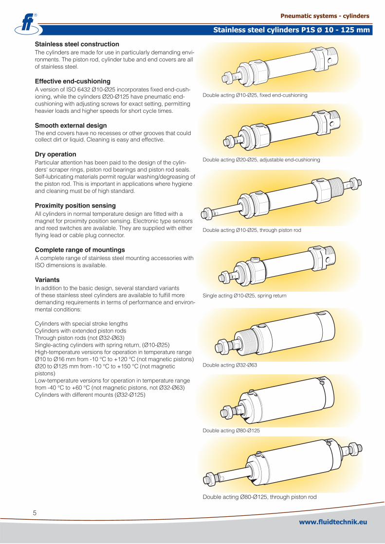
DoubleactingØ10-Ø�5,fixedend-cushioning
Doubleacting�0-�5,adjustableend-cushioning
DoubleactingØ10-Ø�5,throughpistonrod
SingleactingØ10-Ø�5,springreturn
Stainless steel constructionThecylindersaremadeforuseinparticularlydemandingenvi-ronments.Thepistonrod,cylindertubeandendcoversareallofstainlesssteel.
Effective end-cushioningAversionofISO643�Ø10-Ø�5incorporatesfixedend-cush-ioning,whilethecylindersØ�0-Ø1�5havepneumaticend-cushioningwithadjustingscrewsforexactsetting,permittingheavierloadsandhigherspeedsforshortcycletimes.
Smooth external designTheendcovershavenorecessesorothergroovesthatcouldcollectdirtorliquid.Cleaningiseasyandeffective.
Dry operationParticularattentionhasbeenpaidtothedesignofthecylin-ders‘scraperrings,pistonrodbearingsandpistonrodseals.Self-lubricatingmaterialspermitregularwashing/degreasingofthepistonrod.Thisisimportantinapplicationswherehygieneandcleaningmustbeofhighstandard.
Proximity position sensingAllcylindersinnormaltemperaturedesignarefittedwithamagnetforproximitypositionsensing.Electronictypesensorsandreedswitchesareavailable.Theyaresuppliedwitheitherflyingleadorcableplugconnector.
Complete range of mountingsAcompleterangeofstainlesssteelmountingaccessorieswithISOdimensionsisavailable.
VariantsInadditiontothebasicdesign,severalstandardvariantsofthesestainlesssteelcylindersareavailabletofulfillmoredemandingrequirementsintermsofperformanceandenviron-mentalconditions:
CylinderswithspecialstrokelengthsCylinderswithextendedpistonrodsThroughpistonrods(notØ3�-Ø63)Single-actingcylinderswithspringreturn,(Ø10-Ø�5)High-temperatureversionsforoperationintemperaturerangeØ10toØ16mmfrom-10°Cto+1�0°C(notmagneticpistons)Ø�0toØ1�5mmfrom-10°Cto+150°C(notmagneticpistons)Low-temperatureversionsforoperationintemperaturerangefrom-40°Cto+60°C(notmagneticpistons,notØ3�-Ø63)Cylinderswithdifferentmounts(Ø3�-Ø1�5)
DoubleactingØ3�-Ø63
DoubleactingØ80-Ø1�5
DoubleactingØ80-Ø1�5,throughpistonrod
www.fluidtechnik.euwww.fluidtechnik.eu
Pneumatic systems - cylindersPneumatic systems - cylinders
Stainless steel cylinders P1S 10 - 125 mmStainless steel cylinders P1S 10 - 125 mmØØ

6
Guide for selecting suitable tubingTheselectionofthecorrectsizeoftubingisoftenbasedonexpe-rience,withnogreatthoughttooptimizingenergyefficiencyandcylindervelocity.Thisisusuallyacceptable,butmakingaroughcalculationcanresultinworthwhileeconomicgains.
The following is the basic principle:1.Theprimarylinetotheworkingvalvecouldbeoversized(this
doesnotcauseanyextraairconsumptionandconsequentlydoesnotcreateanyextracostsinoperation).
�.Thetubesbetweenthevalveandthecylindershould,ho-wever,beoptimizedaccordingtotheprinciplethatanin-sufficientborethrottlestheflowandthuslimitsthecylinderspeed,whileanoversizedpipecreatesadeadvolumewhichincreasestheairconsumptionandfillingtime.
Thechartbelowisintendedtohelpwhenselectingthecorrectsizeoftubetousebetweenthevalveandthecylinder.
The following prerequisites apply:Thecylinder load should be about 50%ofthetheoreticalforce(=normalload).Alowerloadgivesahighervelocityandviceversa.Thetubesizeisselectedasafunctionofthecylinder bore,thedesiredcylinder velocityandthetube lengthbet-weenthevalveandthecylinder.
Ifyouwanttousethecapacityofthevalvetoitsmaximum,andobtainmaximumspeed,thetubingshouldbechosensothattheyatleastcorrespondwiththeequivalentrestrictiondiameter(seedescriptionbelow),sothatthetubingdoesnotrestrictthetotalflow.Thismeansthatashorttubingmusthaveatleasttheequivalentrestrictiondiameter.Ifthetubingislong-er,chooseitfromthetablebelow.Straightfittingsshouldbechosenforhighestflowrates.(Elbowandbanjofittingscauserestriction.)
1) The“equivalentthrottlingbore“isalongthrottle(forexampleatube)oraseriesofthrottles(forexample,throughavalve)convertedtoashortthrottlewhichgivesacorrespondingflowrate.Thisshouldnotbeconfusedwiththe“orifice“whichissometimesspecifiedforvalves.Thevaluefortheorificedoesnotnormallytakeaccountofthefactthatthevalvecontainsanumberofthrottles.
�) Qnisameasureofthevalveflowcapacity,withflowmeasuredinlitreperminute(l/min)at6bar(e)supplypressureand1barpressuredropacrossthevalve.
CylinderØ[mm]
Equivalentthrottlingbore1) TubeØOut./ØInt.[mm]
Lengthoftubing[m]Cylinderspeed[m/s]0,2 0,5 0,8 1,1 1,4 0 1 2 3 4 5 6 7 8 9 10
1
2
3
4
5
6
7
8
9
10
11
Ø10Ø16Ø20Ø25Ø32Ø40Ø50
Ø63
Ø80
Ø100
Ø125
Ø160
Ø200
14/11–/12
–/13
–/14
–/15
–/16
12/10
10/8
8/6
6/45/34/2,7
200
400
800
1000
1200
14001600
1800200022002400
3000
4000
2800
3200340036003800
2600
4
3
2
1
AirflowQn[Nl/min]
www.fluidtechnik.euwww.fluidtechnik.eu
Pneumatic systems - cylindersPneumatic systems - cylinders
Stainless steel cylinders P1S 10 - 125 mmStainless steel cylinders P1S 10 - 125 mmØØ

7
Example 1 : Which tube diameter should be used?A50mmborecylinderistobeoperatedat0.5m/s.Thetubelengthbetweenthevalveandcylinderis�m.Inthediagramwefollowthelinefrom50mmboreto0.5m/sandgetan“equivalentthrottlingbore“ofapproximately4mm.Wecontinueouttotherightinthechartandintersectthelinefora�mtubebetweenthecurvesfor4mm(6/4tube)and6mm(8/6tube).Thismeansthata6/4tubethrottlesthevelocitysomewhat,whilean8/6tubeisalittletoolarge.Weselectthe8/6tubetoobtainfullcylindervelocity.
Example 2 : What cylinder velocity will be obtained?A80mmborecylinderwillbeused,connectedby8m1�/10tubetoavalvewithQn1�00Nl/min.Whatcylindervelocitywillweget?Werefertothediagramandfollowthelinefrom8mmtubelengthuptothecurvefor1�/10tube.Fromthere,wegohorizontallytothecurvefortheØ80cylinder.Wefindthatthevelocitywillbeabout0.5m/s.
Example 3 : What is the minimum inner diameter and maximum lenght of tube?Foraapplicationa1�5mmborecylinderwillbeused.Maximumvelocityofpistonrodis0.5m/s.ThecylinderwillbecontrolledbyavalvewithQn3�00Nl/min.Whatdiameteroftubecanbeusedandwhatismaximumlenghtoftube.Werefertothediagram.WestartattheleftsideofthediagramcylinderØ1�5.Wefollowthelineuntiltheintersectionwiththevelocitylineof0.5m/s.Fromherewedrawahorizontallineinthediagram.Thislineshowsusweneedanequivalentthrot-tlingboreofapproximately10mm.Followingthislinehorizon-tallywecrossafewintersections.Theseintersectionsshowsustheminimuminnerdiameter(rightsidediagram)incombina-tionwiththemaximumlengthoftube(bottomsidediagram).
Forexample:Intersectionone:Whenatube(14/11)willbeused,themaximumlengthoftubeis0.7meter.Intersectiontwo:Whenatube(—/13)willbeused,themaximumlengthoftubeis3.7meter.Intersectionthree:Whenatube(—/14)willbeused,themaximumlengthoftubeis6meter.
Example 4 : Determining tube size and cylinder velocity with a particular cylinder and valve?Foranapplicationusinga40mmborecylinderwithavalvewithQn=800Nl/min.Thedistancebetweenthecylinderandvalvehasbeensetto5m.Tube dimension: Whattubeboreshouldbeselectedtoobtainthemaximumcylindervelocity?Startatpipelength5m,followthelineuptotheintersectionwith800Nl/min.Selectthenextlargesttubediameter,inthiscaseØ10/8mm.Cylinder velocity:Whatmaximumcylindervelocitywillbeobtained?Followthelinefor800Nl/mintotheleftuntilitinter-sectswiththelinefortheØ40mmcylinder.Inthisexample,thespeedisjustabove1.1m/s.
Valve series with respective flows in Nl/minute
Valve series Qn in Nl/Min
ValvetronicSolstar 33InterfacePS1 100AdexA05 173Moduflexsize1,(�x3/�) ��0ValvetronicPVL-B5/3closedcentre,6mmpushin �90Moduflexsize1,(4/�) 3�0B43Manualandmechanical 340ValvetronicPVL-B�x�/3,6mmpushin 350ValvetronicPVL-B5/3closedcentre,G1/8 370CompactIsomaxDX0� 385ValvetronicPVL-B�x3/�G1/8 440ValvetronicPVL-B5/�,6mmpushin 450ValvetronicPVL-B5/3ventedcentre,6mmpushin 450Moduflexsize�,(�x3/�) 450FlowstarP�V-A 5�0ValvetronicPVL-B5/3ventedcentre,G1/8 540ValvetronicPVL-B5/�,G1/8 540ValvetronicPVL-C�x3/�,8mmpushin 540AdexA1� 560ValvetronicPVL-C�x3/�G1/8 570CompactIsomaxDX01 585VIKINGXtremeP�LAX 660ValvetronicPVL-C5/3closedcentre,8mmpushin 700ValvetronicPVL-C5/3ventedcentre,G1/4 700B3-Series 780ValvetronicPVL-C5/3closedcentre,G1/4 780Moduflexsize�,(4/�) 800ValvetronicPVL-C5/�,8mmpushin 840ValvetronicPVL-C5/3ventedcentre,8mmpushin 840ValvetronicPVL-C5/�,G1/4 840FlowstarP�V-B 1090ISOMAXDX1 1150B53Manualandmechanical 1160B4-Series 1170VIKINGXtremeP�LBX 1�90B5-Series,G1/4 1440AirlineIsolatorValveVE��/�3 1470ISOMAXDX� �330VIKINGXtremeP�LCX,G3/8 �460VIKINGXtremeP�LDX,G1/� �660ISOMAXDX3 4050AirlineIsolatorValveVE4�/43 55�0AirlineIsolatorValveVE8�/83 13680
www.fluidtechnik.euwww.fluidtechnik.eu
Pneumatic systems - cylindersPneumatic systems - cylinders
Stainless steel cylinders P1S 10 - 125 mmStainless steel cylinders P1S 10 - 125 mmØØ
8
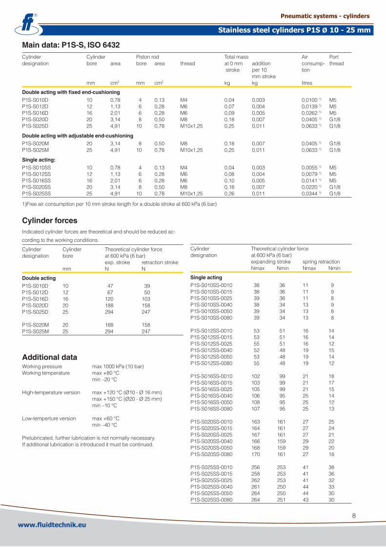
Main data: P1S-S, ISO 6432Cylinder Cylinder Pistonrod Totalmass Air Portdesignation bore area bore area thread at0mm addition consump- thread stroke per10 tion mmstroke mm cm� mm cm� kg kg litres
Double acting with fixed end-cushioning
P1S-S010D 10 0,78 4 0,13 M4 0,04 0,003 0,01001) M5P1S-S01�D 1� 1,13 6 0,�8 M6 0,07 0,004 0,01391) M5P1S-S016D 16 �,01 6 0,�8 M6 0,09 0,005 0,0�6�1) M5P1S-S0�0D �0 3,14 8 0,50 M8 0,18 0,007 0,04051) G1/8P1S-S0�5D �5 4,91 10 0,78 M10x1,�5 0,�5 0,011 0,06331) G1/8
Double acting with adjustable end-cushioning
P1S-S0�0M �0 3,14 8 0,50 M8 0,18 0,007 0,04051) G1/8P1S-S0�5M �5 4,91 10 0,78 M10x1,�5 0,�5 0,011 0,06331) G1/8
Single acting:
P1S-S010SS 10 0,78 4 0,13 M4 0,04 0,003 0,00551) M5P1S-S01�SS 1� 1,13 6 0,�8 M6 0,08 0,004 0,00791) M5P1S-S016SS 16 �,01 6 0,�8 M6 0,10 0,005 0,01411) M5P1S-S0�0SS �0 3,14 8 0,50 M8 0,18 0,007 0,0��01) G1/8P1S-S0�5SS �5 4,91 10 0,78 M10x1,�5 0,�6 0,011 0,03441) G1/8
1)Freeairconsumptionper10mmstrokelengthforadoublestrokeat600kPa(6bar)
Cylinder forcesIndicatedcylinderforcesaretheoreticalandshouldbereducedac-
cordingtotheworkingconditions.
Cylinder Cylinder Theoreticalcylinderforcedesignation bore at600kPa(6bar) exp.stroke retractionstroke mm N N
Double acting
P1S-S010D 10 47 39P1S-S01�D 1� 67 50P1S-S016D 16 1�0 103P1S-S0�0D �0 188 158P1S-S0�5D �5 �94 �47
P1S-S0�0M �0 188 158P1S-S0�5M �5 �94 �47
Additional dataWorkingpressure max1000kPa(10bar)Workingtemperature max+80°C min–�0°C
High-temperatureversion max+1�0°C(Ø10-Ø16mm) max+150°C(Ø�0-Ø�5mm) min–10°C
Low-tempertureversion max+60°C min–40°C
Prelubricated,furtherlubricationisnotnormallynecessary.Ifadditionallubricationisintroduceditmustbecontinued.
Cylinder Theoreticalcylinderforcedesignation at600kPa(6bar) expandingstroke springretraction Nmax Nmin Nmax Nmin
Single acting
P1S-S010SS-0010 38 36 11 9P1S-S010SS-0015 38 36 11 9P1S-S010SS-00�5 39 36 11 8P1S-S010SS-0040 38 34 13 9P1S-S010SS-0050 39 34 13 8P1S-S010SS-0080 39 34 13 8
P1S-S01�SS-0010 53 51 16 14P1S-S01�SS-0015 53 51 16 14P1S-S01�SS-00�5 55 51 16 1�P1S-S01�SS-0040 5� 48 19 15P1S-S01�SS-0050 53 48 19 14P1S-S01�SS-0080 55 48 19 1�
P1S-S016SS-0010 10� 99 �1 18P1S-S016SS-0015 103 99 �1 17P1S-S016SS-00�5 105 99 �1 15P1S-S016SS-0040 106 95 �5 14P1S-S016SS-0050 108 95 �5 1�P1S-S016SS-0080 107 95 �5 13
P1S-S0�0SS-0010 163 161 �7 �5P1S-S0�0SS-0015 164 161 �7 �4P1S-S0�0SS-00�5 167 161 �7 �1P1S-S0�0SS-0040 166 159 �9 ��P1S-S0�0SS-0050 168 159 �9 �0P1S-S0�0SS-0080 170 161 �7 18
P1S-S0�5SS-0010 �56 �53 41 38P1S-S0�5SS-0015 �58 �53 41 36P1S-S0�5SS-00�5 �6� �53 41 3�P1S-S0�5SS-0040 �61 �50 44 33P1S-S0�5SS-0050 �64 �50 44 30P1S-S0�5SS-0080 �64 �51 43 30
www.fluidtechnik.euwww.fluidtechnik.eu
Pneumatic systems - cylindersPneumatic systems - cylinders
Stainless steel cylinders P1S 10 - 25 mmStainless steel cylinders P1S 10 - 25 mmØØ
9
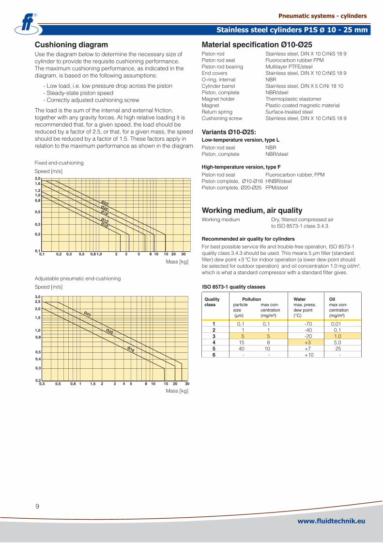
Cushioning diagramUsethediagrambelowtodeterminethenecessarysizeofcylindertoprovidetherequisitecushioningperformance.Themaximumcushioningperformance,asindicatedinthediagram,isbasedonthefollowingassumptions:
-Lowload,i.e.lowpressuredropacrossthepiston-Steady-statepistonspeed-Correctlyadjustedcushioningscrew
Theloadisthesumoftheinternalandexternalfriction,togetherwithanygravityforces.Athighrelativeloadingitisrecommendedthat,foragivenspeed,theloadshouldbereducedbyafactorof�.5,orthat,foragivenmass,thespeedshouldbereducedbyafactorof1.5.Thesefactorsapplyinrelationtothemaximumperformanceasshowninthediagram.
Fixedend-cushioning
Speed[m/s]
Material specification Ø10-Ø25Pistonrod Stainlesssteel,DINX10CrNiS189Pistonrodseal FluorocarbonrubberFPMPistonrodbearing MultilayerPTFE/steelEndcovers Stainlesssteel,DINX10CrNiS189O-ring,internal NBRCylinderbarrel Stainlesssteel,DINX5CrNi1810Piston,complete NBR/steelMagnetholder ThermoplasticelastomerMagnet Plastic-coatedmagneticmaterialReturnspring Surface-treatedsteelCushioningscrew Stainlesssteel,DINX10CrNiS189
Variants Ø10-Ø25:Low-temperature version, type L
Pistonrodseal NBRPiston,complete NBR/steel
High-temperature version, type F
Pistonrodseal Fluorocarbonrubber,FPMPistoncomplete,Ø10-Ø16 HNBR/steelPistoncomplete,Ø�0-Ø�5 FPM/steel
Mass[kg]
Adjustablepneumaticend-cushioning
Speed[m/s]
Mass[kg]
0,1
0,2
0,3
0,5
0,81,01,2
1,62,0
0,1 0,2 0,3 0,5 0,8 1,0 2 3 5 8 10 15 20
Ø10
Ø12
Ø16
Ø20
Ø25
30
0,3 0,5 0,8 1 1,5 2 3 4 5 8 10 15 20 300,2
0,3
0,4
0,5
0,8
1,0
1,5
2,0
2,53,0
Ø25
Ø20
Ø16
Working medium, air quality Workingmedium Dry,filteredcompressedair toISO8573-1class3.4.3.
Recommended air quality for cylinders
Forbestpossibleservicelifeandtrouble-freeoperation,ISO8573-1qualityclass3.4.3shouldbeused.Thismeans5µmfilter(standardfilter)dewpoint+3ºCforindooroperation(alowerdewpointshouldbeselectedforoutdooroperation)andoilconcentration1.0mgoil/m3,whichiswhatastandardcompressorwithastandardfiltergives. ISO 8573-1 quality classes
Quality Pollution Water Oil class particle max con- max. press. max con- size centration dew point centration (µm) (mg/m³) (°C) (mg/m³)
1 0,1 0,1 -70 0,01 2 1 1 -40 0,1 3 5 5 -�0 1,0 4 15 8 +3 5,0 5 40 10 +7 �5 6 - - +10 -
www.fluidtechnik.euwww.fluidtechnik.eu
Pneumatic systems - cylindersPneumatic systems - cylinders
Stainless steel cylinders P1S 10 - 25 mmStainless steel cylinders P1S 10 - 25 mmØØ
10
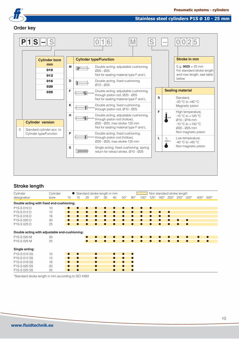
Order key
P 1 S – S 0 1 6 M S – 0 0 2 5
Stroke lengthCylinder Cylinder Standardstrokelengthinmm Nonstandardstrokelengthdesignation bore 10 15 �0 �5* 30 40 50* 80* 100* 1�5* 160* �00* �50* 3�0* 400* 500*
Double acting with fixed end-cushioning:
P1S-S010D 10 • • • • • • • • • •P1S-S01�D 1� • • • • • • • • • • • •P1S-S016D 16 • • • • • • • • • • • •P1S-S0�0D �0 • • • • • • • • • • • • • •P1S-S0�5D �5 • • • • • • • • • • • • • •Double acting with adjustable end-cushioning:
P1S-S0�0M �0 • • • • • • • • • • • • • •P1S-S0�5M �5 • • • • • • • • • • • • • •Single acting:
P1S-S010SS 10 • • • • • •P1S-S01�SS 1� • • • • • •P1S-S016SS 16 • • • • • •P1S-S0�0SS �0 • • • • • •P1S-S0�5SS �5 • • • • • •*StandardstrokelengthinmmaccordingtoISO4393
Cylinder type/Function
M Doubleacting,adjustablecushioning �0-�5 NotforsealingmaterialtypeFandL
D Doubleacting,fixedcushioning Ø10-Ø�5
F Doubleacting,adjustablecushioning, throughpistonrod,�0-�5 NotforsealingmaterialtypeFandL
K Doubleacting,fixedcushioning, throughpistonrod,Ø10-Ø�5
H Doubleacting,adjustablecushioning, throughpistonrod(hollow), �0-�5,maxstroke1�5mm NotforsealingmaterialtypeFandL
P Doubleacting,fixedcushioning, throughpistonrod(hollow), �0-�5,maxstroke1�5mm
S Singleacting,fixedcushioning,spring returnforretractstroke,Ø10-Ø�5
Sealing material
S Standard, -�0°Cto+80°C Magneticpiston
F Hightemperature, -10°Cto+1�0°C Ø10-Ø16mm -10°Cto+150°C Ø�0-Ø�5mm Nonmagneticpiston
L Lowtemperature, -40°Cto+60°C Nonmagneticpiston
Stroke in mm
E.g.0025=�5mmForstandardstrokelengthandmaxlength,seetablebelow
Cylinder version
S Standardcylinderacc.to Cylindertype/Function
Cylinder bore mm
010
012
016
020
025
www.fluidtechnik.euwww.fluidtechnik.eu
Pneumatic systems - cylindersPneumatic systems - cylinders
Stainless steel cylinders P1S 10 - 25 mmStainless steel cylinders P1S 10 - 25 mmØØ

11
AM
ZJ
XC
L
BF
ØB
E
ØC
D
AF
WHPSW
ØK
K
ØB
E
EW
C
H
EEAF
ØK
K
ØB
E
DimensionsCyl.bore AM0/-� BE AF BF C CDH9EE EW H KK L SW WH±1,�mm mm mm mm mm mm mm mm mm mm mm
10 1� M1�x1,�5 1� 10 14 4 M5 8 19 M4 6 – 161� 16 M16x1,5 18 13 18 6 M5 1� 19 M6 9 5 ��16 16 M16x1,5 18 13 18 6 M5 1� 19 M6 9 5 ���0 �0 M��x1,5 �0 14 �4 8 G1/8 16 �9 M8 1� 7 �4�5 �� M��x1,5 �� 14 �8 8 G1/8 16 3� M10x1,�5 1� 9 �8
Double acting cylindersCyl.bore XC ZJ Pmm mm mm mm
10 64+stroke 84+stroke 46+stroke1� 75+stroke 99+stroke 48+stroke16 8�+stroke 104+stroke 53+stroke�0 95+stroke 1�5+stroke 67+stroke�5 104+stroke 13�+stroke 68+stroke
Single acting with spring return, type SSStroke/ 10 15 �5 40 50 80 10 15 �5 40 50 80 10 15 �5 40 50 80Cyl.bore XC XC XC XC XC XC ZJ ZJ ZJ ZJ ZJ ZJ P P P P P Pmm mm mm mm mm mm mm mm mm mm mm mm mm mm mm mm mm mm mm
10 74 79 89 1�6 136 174 94 99 109 146 156 194 56 61 71 108 118 1561� 85 90 100 13� 14� 185 109 114 1�4 156 166 �09 58 63 73 105 115 15816 9� 97 107 1�� 13� 184 114 119 1�9 144 154 �06 63 68 78 93 103 155�0 105 110 1�0 135 145 191 135 140 150 165 175 ��1 77 8� 9� 107 117 163�5 114 119 1�9 144 154 �01 14� 147 157 17� 18� ��9 78 83 93 108 118 165
Lengthtolerances ±1mmStrokelengthtolerances +1,5/0mm
Cylindersaresuppliedcompletewithmountingandadjustingnuts.Cylinderswiththroughpistonrodaresuppliedcompletewithtwoadjustingnutsandonemountingnut.
Refer to order code when ordering cylindersSeeOrderkeyonpage10
WH + stroke
CAD drawings on the InternetOurhomepagewww.parker.com/euro_pneumaticincludestheAirCadDrawingLibrarywith�Dand3Ddrawingsforthemainversions.
www.fluidtechnik.euwww.fluidtechnik.eu
Pneumatic systems - cylindersPneumatic systems - cylinders
Stainless steel cylinders P1S 10 - 25 mmStainless steel cylinders P1S 10 - 25 mmØØ
1�
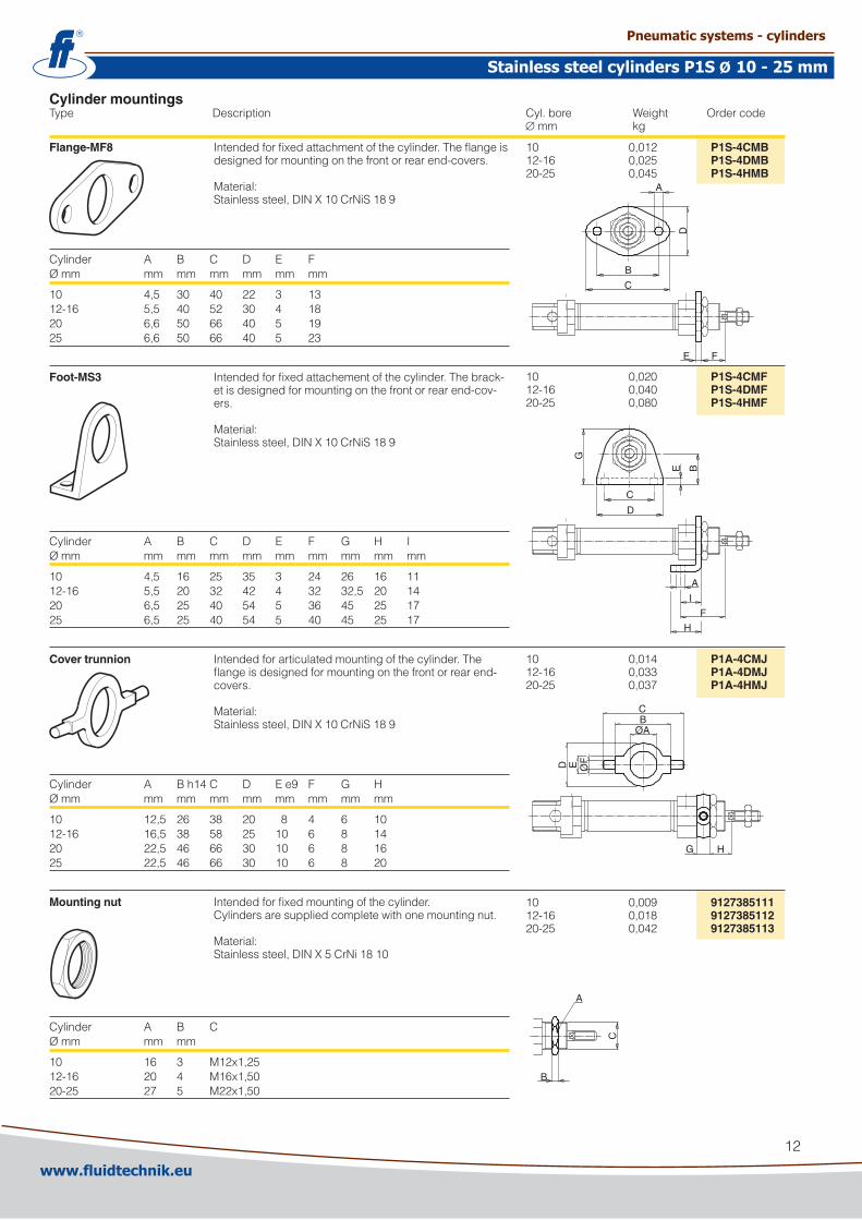
Flange-MF8 Intendedforfixedattachmentofthecylinder.Theflangeisdesignedformountingonthefrontorrearend-covers.Material:Stainlesssteel,DINX10CrNiS189
Cylinder A B C D E FØmm mm mm mm mm mm mm
10 4,5 30 40 �� 3 131�-16 5,5 40 5� 30 4 18�0 6,6 50 66 40 5 19�5 6,6 50 66 40 5 �3
Foot-MS3 Intendedforfixedattachementofthecylinder.Thebrack-etisdesignedformountingonthefrontorrearend-cov-ers.Material:Stainlesssteel,DINX10CrNiS189
Cylinder A B C D E F G H IØmm mm mm mm mm mm mm mm mm mm
10 4,5 16 �5 35 3 �4 �6 16 111�-16 5,5 �0 3� 4� 4 3� 3�,5 �0 14�0 6,5 �5 40 54 5 36 45 �5 17�5 6,5 �5 40 54 5 40 45 �5 17
Cover trunnion Intendedforarticulatedmountingofthecylinder.Theflangeisdesignedformountingonthefrontorrearend-covers.Material:Stainlesssteel,DINX10CrNiS189
Cylinder A Bh14C D Ee9 F G HØmm mm mm mm mm mm mm mm mm
10 1�,5 �6 38 �0 8 4 6 101�-16 16,5 38 58 �5 10 6 8 14�0 ��,5 46 66 30 10 6 8 16�5 ��,5 46 66 30 10 6 8 �0
Mounting nut Intendedforfixedmountingofthecylinder.Cylindersaresuppliedcompletewithonemountingnut.Material:Stainlesssteel,DINX5CrNi1810
Cylinder A B CØmm mm mm
10 16 3 M1�x1,�51�-16 �0 4 M16x1,50�0-�5 �7 5 M��x1,50
Cylinder mountingsType Description Cyl.bore Weight Ordercode ∅ mm kg
10 0,01� P1S-4CMB1�-16 0,0�5 P1S-4DMB�0-�5 0,045 P1S-4HMB
10 0,0�0 P1S-4CMF1�-16 0,040 P1S-4DMF�0-�5 0,080 P1S-4HMF
10 0,014 P1A-4CMJ1�-16 0,033 P1A-4DMJ�0-�5 0,037 P1A-4HMJ
10 0,009 91273851111�-16 0,018 9127385112�0-�5 0,04� 9127385113
D
C
G
E B
A
I
F
H
E F
A
D
B
C
ØA
D E ØF
BC
G H
A
B
C
www.fluidtechnik.euwww.fluidtechnik.eu
Pneumatic systems - cylindersPneumatic systems - cylinders
Stainless steel cylinders P1S 10 - 25 mmStainless steel cylinders P1S 10 - 25 mmØØ
13
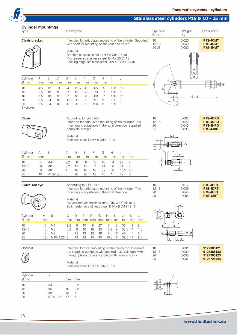
Cylinder mountingsType Description Cyl.bore Weight Ordercode ∅ mm kg
Clevis bracket Intendedforarticulatedmountingofthecylinder.Suppliedwithshaftformountingontherearendcover.Material:Bracket:stainlesssteel,DINX5CrNi1810Pin:temperedstainlesssteel,DINX�0Cr13Lockingrings:stainlesssteel,DINX5CrNi1810
Cylinder A B C D E F G H I JØmm mm mm mm mm mm mm mm mm ° °
10 4,5 13 8 �4 1�,5 �0 65,3 5 160 171� 5,5 18 1� �7 15 �5 73 7 170 1516 5,5 18 1� �7 15 �5 80 7 170 15�0 6,5 �4 16 30 �0 3� 91 10 165 10�5 6,5 �4 16 30 �0 3� 100 10 165 10S=stroke
Clevis AccordingtoISO8140Intendedforarticulatedmountingofthecylinder.Thismountingisadjustableintheaxialdirection.Suppliedcompletewithpin.Material:Stainlesssteel,DINX5CrNi1810
Cylinder A B C D E F G H I JØmm mm mm mm mm mm mm mm mm mm
10 4 M4 �,� 8 8 5 16 4 �� �1�-16 6 M6 3,� 1� 1� 7 �4 6 31 3�0 8 M8 4 16 16 10 3� 8 40,5 3,5�5 10 M10x1,�5 5 �0 �0 1� 40 10 49 3
Swivel rod eye AccordingtoISO8139Intendedforarticulatedmountingofthecylinder.Thismountingisadjustableintheaxialdirection.Material:Swivelrodeye:stainlesssteel,DINX5CrNi1810Ball:hardenedstainlesssteel,DINX5CrNi1810
Cylinder A B C D E F G H I J K LØmm mm mm mm mm mm mm mm mm mm mm mm
10 5 M4 �,� 8 10 9 �7 6 8 33 9 �1�-16 6 M6 3,� 9 10 10 30 6,8 9 38,5 11 1,5�0 8 M8 4 1� 1� 1� 36 9 1� 46 14 ��5 10 M10x1,�5 5 14 14 14 43 10,5 15 5�,5 17 �,5
Rod nut Intendedforfixedmountingonthepistonrod.Cylindersaresuppliedcompletewithonerodnut.(cylinderswiththroughpistonrodaresuppliedwithtworodnuts.)Material:Stainlesssteel,DINX5CrNi1810
Cylinder D F EØmm mm mm
10 M4 7 �,�1�-16 M6 10 3,��0 M8 13 4�5 M10x1,�5 17 5
10 0,0�0 P1S-4CMT1�-16 0,040 P1S-4DMT�0-�5 0,080 P1S-4HMT
10 0,007 P1S-4CRD1�-16 0,0�� P1S-4DRD�0 0,045 P1S-4HRD�5 0,095 P1S-4JRD
10 0,017 P1S-4CRT1�-16 0,0�5 P1S-4DRT�0 0,045 P1S-4HRT�5 0,085 P1S-4JRT
10 0,001 91273851211�-16 0,00� 9127385122�0 0,005 9127385123�5 0,007 9126725404
I±J
D
C G
E F
A
H DB
A
J±LC G
I E F
B H D
A
C
BH
D
EF
J
G + S
I
E
F
D
www.fluidtechnik.euwww.fluidtechnik.eu
Pneumatic systems - cylindersPneumatic systems - cylinders
Stainless steel cylinders P1S 10 - 25 mmStainless steel cylinders P1S 10 - 25 mmØØ

14
Main data: ISO 6431Cylinder Cylinder Pistonrod Cushio- Totalmass Movingmass Air Portdesignation bore area diam. area thread ning at addition at addition consump- thread distance 0mm per10 0mm per10 tion stroke mmstroke stroke mmstroke mm cm� mm cm� mm kg kg kg kg litres
P1S-•03�M 3� 8,0 1� 1,1 M10x1,�5 15 0,59 0,0�6 0,10 0,009 0,1051) G1/8P1S-•040M 40 1�,6 16 �,0 M1�x1,�5 18 0,99 0,036 0,19 0,016 0,16�1) G1/4P1S-•050M 50 19,6 �0 3,1 M16x1,5 19 1,63 0,057 0,3� 0,0�4 0,�531) G1/4P1S-•063M 63 31,� �0 3,1 M16x1,5 �� �,75 0,065 0,36 0,0�4 0,4141) G3/8
P1S-•080M 80 50,3 �5 4,9 M�0x1,5 �4 5,09 0,099 1,11 0,039 0,6691) G3/8P1S-•100M 100 78,5 �5 4,9 M�0x1,5 �9 8,68 0,115 1,41 0,039 1,0431) G1/�P1S-•1�5M 1�5 1��,7 3� 8,0 M�7x� 3� 15,31 0,174 �,90 0,063 1,66�1) G1/�
1)Freeairconsumptionper10mmstrokelengthforadoublestrokeat600kPa(6bar)
Cylinder forcesIndicatedcylinderforcesaretheoreticalandshouldbereducedinrelationtoworkingconditions.
Cylinder Theoreticalcylinderforcedesignation at600kPa(6bar) exp.stroke returnstroke N N
P1S-•03�M 480 415P1S-•040M 754 633P1S-•050M 1180 990P1S-•063M 1870 1680
P1S-•080M 3016 �7�1P1S-•100M 471� 4417P1S-•1�5M 7363 6880
Additional dataWorkingpressure max 10barWorkingtemperature max +80°C min –�0°C
High-temperatureversion max+150°C min –10°C
Low-temperatureversion max +40°CØ80-Ø1�5 min –40°C
Prelubricated,furtherlubricationisnotnormallynecessary.Ifadditionallubricationisintroduceditmustbecontinued.
Cushioning diagramUsethediagrambelowtodeterminethenecessarysizeofcylindertoprovidetherequisitecushioningperformance.Themaximumcushion-ingperformance,asindicatedinthediagram,isbasedonthefollow-ingassumptions:
–Lowload,i.e.lowpressuredropacrossthepiston–Steady-statepistonspeed–Correctlyadjustedcushioningscrew
Theloadisthesumoftheinternalandexternalfriction,togetherwithanygravityforces.Athighrelativeloadingitisrecommendedthat,foragivenspeed,theloadshouldbereducedbyafactorof�.5,orthat,foragivenmass,thespeedshouldbereducedbyafactorof1.5.Thesefactorsapplyinrelationtothemaximumperformanceasshowninthediagram.
Speed[m/s]
1 2 3 5 10 20 30 50 100 200 500 10003000,1
0,2
0,3
0,5
1,0
2,0
3,0
5,0
Ø32 Ø40 Ø50Ø63
Ø80Ø100
Ø125
Mass[kg]
Working medium, air quality Workingmedium Dry,filteredcompressedair toISO8573-1class3.4.3.
Recommended air quality for cylinders
Forbestpossibleservicelifeandtrouble-freeoperation,ISO8573-1qualityclass3.4.3shouldbeused.Thismeans5µmfilter(standardfilter)dewpoint+3ºCforindooroperation(alowerdewpointshouldbeselectedforoutdooroperation)andoilconcentration1.0mgoil/m3,whichiswhatastandardcompressorwithastandardfiltergives. ISO 8573-1 quality classes
Quality Pollution Water Oil class particle max con- max. press. max con- size centration dew point centration (µm) (mg/m³) (°C) (mg/m³)
1 0,1 0,1 -70 0,01 2 1 1 -40 0,1 3 5 5 -�0 1,0 4 15 8 +3 5,0 5 40 10 +7 �5 6 - - +10 -
www.fluidtechnik.euwww.fluidtechnik.eu
Stainless steel cylinders P1S 32 - 125 mmStainless steel cylinders P1S 32 - 125 mmØØ
Pneumatic systems - cylindersPneumatic systems - cylinders
15
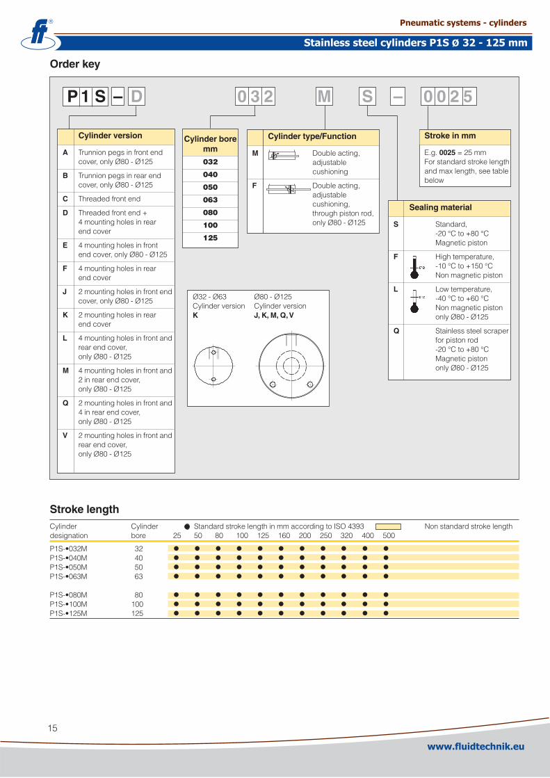
Order key
P 1 S – D 0 3 2 M S – 0 0 2 5
Stroke lengthCylinder Cylinder StandardstrokelengthinmmaccordingtoISO4393 Nonstandardstrokelengthdesignation bore �5 50 80 100 1�5 160 �00 �50 3�0 400 500
P1S-•03�M 3� • • • • • • • • • • •P1S-•040M 40 • • • • • • • • • • •P1S-•050M 50 • • • • • • • • • • •P1S-•063M 63 • • • • • • • • • • •P1S-•080M 80 • • • • • • • • • • •P1S-•100M 100 • • • • • • • • • • •P1S-•1�5M 1�5 • • • • • • • • • • •
Ø3�-Ø63 Ø80-Ø1�5Cylinderversion CylinderversionK J, K, M, Q, V
Cylinder version
A Trunnionpegsinfrontend cover,onlyØ80-Ø1�5
B Trunnionpegsinrearend cover,onlyØ80-Ø1�5
C Threadedfrontend
D Threadedfrontend+ 4mountingholesinrear endcover
E 4mountingholesinfront endcover,onlyØ80-Ø1�5
F 4mountingholesinrear endcover
J �mountingholesinfrontend cover,onlyØ80-Ø1�5
K �mountingholesinrear endcover
L 4mountingholesinfrontand rearendcover, onlyØ80-Ø1�5
M 4mountingholesinfrontand �inrearendcover, onlyØ80-Ø1�5
Q �mountingholesinfrontand 4inrearendcover, onlyØ80-Ø1�5
V �mountingholesinfrontand rearendcover, onlyØ80-Ø1�5
Cylinder bore mm
032
040
050
063
080
100
125
Cylinder type/Function
M Doubleacting, adjustable cushioning
F Doubleacting, adjustable cushioning, throughpistonrod, onlyØ80-Ø1�5
Stroke in mm
E.g.0025=�5mmForstandardstrokelengthandmaxlength,seetablebelow
Sealing material
S Standard, -�0°Cto+80°C Magneticpiston
F Hightemperature, -10°Cto+150°C Nonmagneticpiston
L Lowtemperature, -40°Cto+60°C Nonmagneticpiston onlyØ80-Ø1�5
Q Stainlesssteelscraper forpistonrod -�0°Cto+80°C Magneticpiston onlyØ80-Ø1�5
www.fluidtechnik.euwww.fluidtechnik.eu
Stainless steel cylinders P1S 32 - 125 mmStainless steel cylinders P1S 32 - 125 mmØØ
Pneumatic systems - cylindersPneumatic systems - cylinders

16
Dimensions Ø32-Ø63Cylinder AA AM B BF BE C D EE F I KK MM O PL RD RTdesignation mm mm mm mm mm mm mm mm mm mm mm mm mm
P1S-D03�M �4,5 �� 15 �5 M30x1,5 88 36 G1/8 4,� 6 M10x1,�5 1� 8 13 30 M5P1S-D040M 30 �4 18 30 M38x1,5 97 44 G1/4 4,5 9 M1�x1,�5 16 9,5 15 38 M6P1S-D050M 39 3� 18 33 M45x1,5 101 55 G1/4 4,5 9 M16x1,5 �0 9,5 15 45 M6P1S-D063M 49 3� �5 33 M45x1,5 117 68 G3/8 4,5 9 M16x1,5 �0 13,3 �0,5 45 M8
Cylinder S SW T V WH ZJ Mountingtolerances Strokelengthdesignation x f 0-500mm mm mm mm mm mm mm mm mm mm
P1S-D03�M 1,5 10 1�,� �6 35,5 1�3,5 1,� �,5 +�,0P1S-D040M 1,5 14 16,5 35 44 141 1,0 �,� +�,0P1S-D050M 1,5 17 �� 41 47 148 0,9 �,3 +�,0P1S-D063M 1,5 17 �6 41 47 164 1,4 �,3 +�,5
Material specification Ø32-Ø63Pistonrod Stainlesssteel,DINX�CrNiMo1713�Pistonrodnut Stainlesssteel,DINX5CrNi1810Pistonrodseal UHMWPE-plastic/NBRScraperring UHMWPE-plastic/fluorocarbon rubber,FPMPistonrodbearing HDPE-plasticEndcovers Stainlesssteel,DINX5CrNi1810Cushioningscrew Stainlesssteel,DINX10CrNiS189Cushioningscrewlockings Stainlesssteel,DINX5CrNi1810Cushioningsealing NBRO-ring,cushioningscrew Fluorocarbon,FPMO-ring,internal NBRCylinderbarrel Stainlesssteel,DINX5CrNi1810Piston POMplasticPistonseal NBRPistonnut ZincplatedsteelMagnet Plastic-coatedmagneticmaterial
Variants Ø32-Ø63:High-temperature version, type F:
Sealings/scraperring Fluorocarbonrubber,FPMPiston Anodizedaluminium
Refer to order code when ordering cylindersSeeOrderkeyonpage15
ØB
EE
T
PL F
BF
WH±f
AM
SW
I
O
ØR
DØ
KK
ØM
M
ØB
E
ØV
ØD
ØRT (4x)
S
AA
AA
Not threaded front end
C + stroke
ZJ ±x + stroke
CAD drawings on the InternetOurhomepagewww.parker.com/euro_pneumaticincludestheAirCadDrawingLibrarywith�Dand3Ddrawingsforthemainversions.
www.fluidtechnik.euwww.fluidtechnik.eu
Stainless steel cylinders P1S 32 - 125 mmStainless steel cylinders P1S 32 - 125 mmØØ
Pneumatic systems - cylindersPneumatic systems - cylinders

17
Dimensions Ø80-Ø125Cylinder AA AM B BE C D EE F KK I J MM N PL Qdesignation mm mm mm mm mm mm mm mm mm mm mm mm
P1S-•080M 46 40 50 M50x1,5 141 86 G3/8 4 M�0x1,5 10 �4,5 �5 84 1�,5 40P1S-•100M 60 40 50 M50x1,5 158 106 G1/� 4 M�0x1,5 8 30 �5 104 15,5 49,5P1S-•1�5M 76 54 60 M60x� 183 133 G1/� 4 M�7x� 13 30 3� 1�9 15,5 6�,5
Cylinder RT SW TC TO T1 UT VD WH XG X3 ZJ ZM Mountingtol. Strokelengthdesignation x f 0-500mm mm mm mm mm mm mm mm mm mm mm mm mm mm mm
P1S-•080M M8 �1 98 �0 �5 1�5 19 37 49,5 165,5178 �15 1,5 �,5 +�,5P1S-•100M M10 �1 109 �5 3� 15� 19 35 50,5 177,5193 ��8 1,5 �,5 +�,5P1S-•1�5M M1� �7 134 �5 3� 177 �4 47 63 �14 �30 �77 �,0 �,5 +4,0
Material specification Ø80-Ø125Pistonrod Stainlesssteel,DINX�CrNiMo1713�Pistonrodnut Acid-proofsteel,A4Pistonrodseal FPMScraperring PTFEPistonrodbearing MultilayerPTFEandsteelEndcovers Stainlesssteel,DINX5CrNi1810Cushioningscrew Stainlesssteel,DINX10CrNiS189Cushioningsealing NBRO-ring,cushioningscrew Fluorocarbon,FPMO-ring,internal NBRCylinderbarrel Stainlesssteel,DINX5CrNi1810Piston AnodizedaluminiumPistonseal NBRPistonbearing UHMWPE-plasticMagneticband Rubber-coatedmagneticmaterial
Variants Ø80-Ø125:Low-temperature version, type L:
Sealings/scraperring NBR/PTFE
High-temperature version, type F:
Sealings/scraperring Fluorocarbonrubber,FPM/PTFE
Cylinders with steel scraper ring, type Q:
Sealings/scraperring NBR/Stainlesssteel
Refer to order code when ordering cylindersSeeOrderkeyonpage15
ØN
PL VD
WH±f
AM
J
EE I SW
ØK
K
ØM
M
ØB
ØD
Q
XGTC
UT
ØTO
ØT
1
F
ØB
E
AA
Q
ØRT (4x)
AA
Through piston rod Basic cylinder
Trunnion pegs on front or rear end cover Threaded front end Mounting holes in the end covers
C + stroke
ZJ ±x + stroke
WH ±f + stroke
ZM + 2 x stroke
XJ + stroke
CAD drawings on the InternetOurhomepagewww.parker.com/euro_pneumaticincludestheAirCadDrawingLibrarywith�Dand3Ddrawingsforthemainversions.
www.fluidtechnik.euwww.fluidtechnik.eu
Stainless steel cylinders P1S 32 - 125 mmStainless steel cylinders P1S 32 - 125 mmØØ
Pneumatic systems - cylindersPneumatic systems - cylinders
18
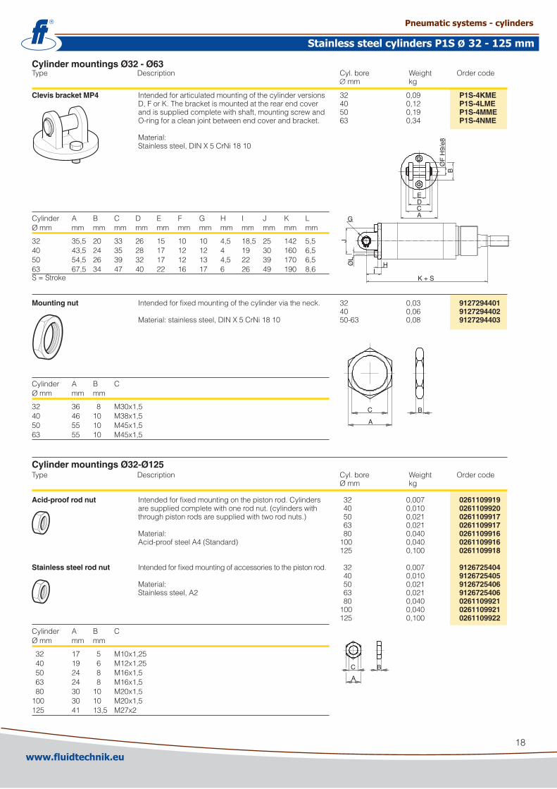
Cylinder mountings Ø32 - Ø63Type Description Cyl.bore Weight Ordercode ∅ mm kg
Clevis bracket MP4 IntendedforarticulatedmountingofthecylinderversionsD,ForK.Thebracketismountedattherearendcoverandissuppliedcompletewithshaft,mountingscrewandO-ringforacleanjointbetweenendcoverandbracket.Material:Stainlesssteel,DINX5CrNi1810
Cylinder A B C D E F G H I J K LØmm mm mm mm mm mm mm mm mm mm mm mm mm
3� 35,5 �0 33 �6 15 10 10 4,5 18,5 �5 14� 5,540 43,5 �4 35 �8 17 1� 1� 4 19 30 160 6,550 54,5 �6 39 3� 17 1� 13 4,5 �� 39 170 6,563 67,5 34 47 40 �� 16 17 6 �6 49 190 8,6S=Stroke
Mounting nut Intendedforfixedmountingofthecylinderviatheneck.Material:stainlesssteel,DINX5CrNi1810
Cylinder A B CØmm mm mm
3� 36 8 M30x1,540 46 10 M38x1,550 55 10 M45x1,563 55 10 M45x1,5
3� 0,09 P1S-4KME40 0,1� P1S-4LME50 0,19 P1S-4MME63 0,34 P1S-4NME
3� 0,03 912729440140 0,06 912729440250-63 0,08 9127294403
3� 0,007 0261109919 40 0,010 0261109920 50 0,0�1 0261109917 63 0,0�1 0261109917 80 0,040 0261109916100 0,040 02611099161�5 0,100 0261109918
3� 0,007 9126725404 40 0,010 9126725405 50 0,0�1 9126725406 63 0,0�1 9126725406 80 0,040 0261109921100 0,040 02611099211�5 0,100 0261109922
G
JØ
L
IH
K + S
EDCA
BØ
F H
9/e8
C
A
B
C
A
B
Cylinder mountings Ø32-Ø125Type Description Cyl.bore Weight Ordercode Ømm kg
Acid-proof rod nut Intendedforfixedmountingonthepistonrod.Cylindersaresuppliedcompletewithonerodnut.(cylinderswiththroughpistonrodsaresuppliedwithtworodnuts.)Material:Acid-proofsteelA4(Standard)
Stainless steel rod nut Intendedforfixedmountingofaccessoriestothepistonrod.Material:Stainlesssteel,A�
Cylinder A B CØmm mm mm
3� 17 5 M10x1,�5 40 19 6 M1�x1,�5 50 �4 8 M16x1,5 63 �4 8 M16x1,5 80 30 10 M�0x1,5100 30 10 M�0x1,51�5 41 13,5 M�7x�
www.fluidtechnik.euwww.fluidtechnik.eu
Stainless steel cylinders P1S 32 - 125 mmStainless steel cylinders P1S 32 - 125 mmØØ
Pneumatic systems - cylindersPneumatic systems - cylinders
19
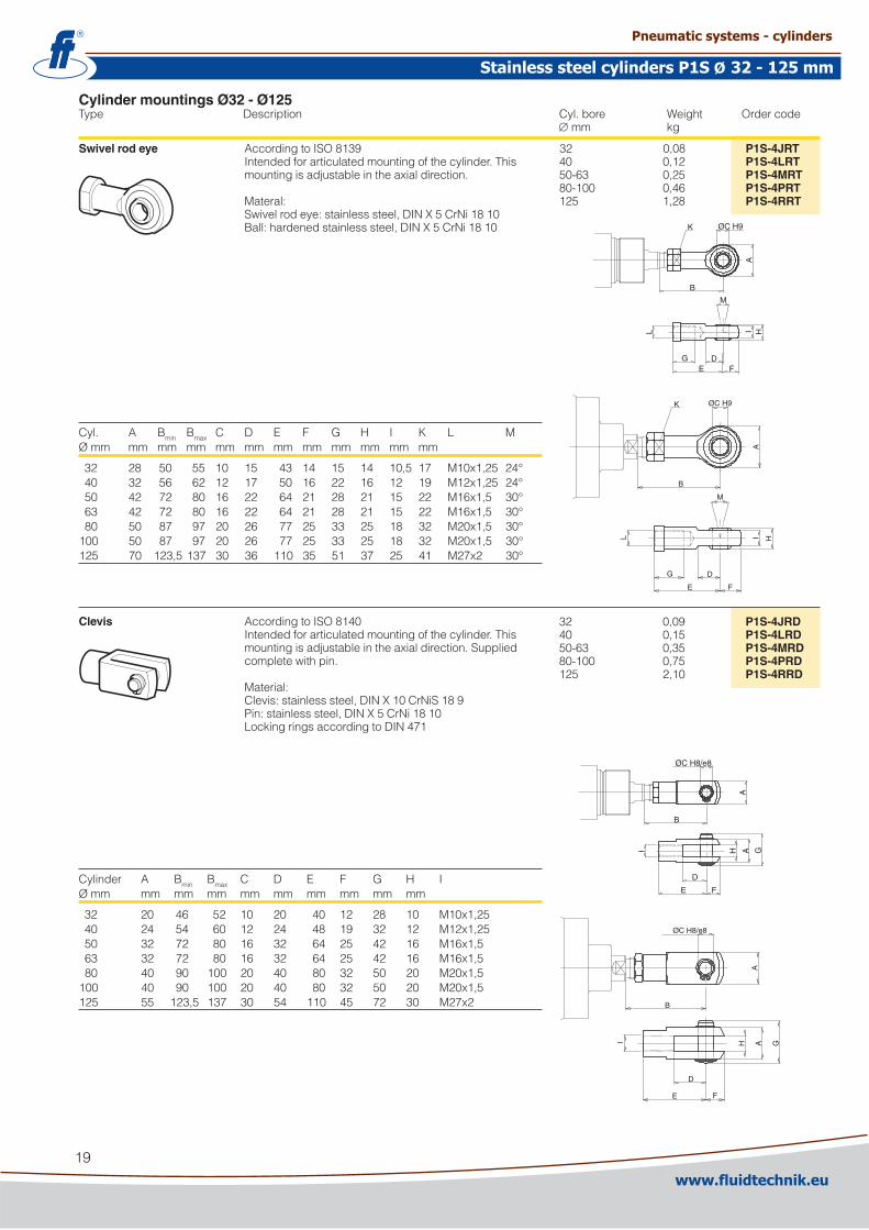
Cylinder mountings Ø32 - Ø125Type Description Cyl.bore Weight Ordercode ∅ mm kg
Swivel rod eye AccordingtoISO8139Intendedforarticulatedmountingofthecylinder.Thismountingisadjustableintheaxialdirection.Materal:Swivelrodeye:stainlesssteel,DINX5CrNi1810Ball:hardenedstainlesssteel,DINX5CrNi1810
Cyl. A Bmin Bmax C D E F G H I K L MØmm mm mm mm mm mm mm mm mm mm mm mm
3� �8 50 55 10 15 43 14 15 14 10,5 17 M10x1,�5 �4° 40 3� 56 6� 1� 17 50 16 �� 16 1� 19 M1�x1,�5 �4° 50 4� 7� 80 16 �� 64 �1 �8 �1 15 �� M16x1,5 30° 63 4� 7� 80 16 �� 64 �1 �8 �1 15 �� M16x1,5 30° 80 50 87 97 �0 �6 77 �5 33 �5 18 3� M�0x1,5 30°100 50 87 97 �0 �6 77 �5 33 �5 18 3� M�0x1,5 30°1�5 70 1�3,5137 30 36 110 35 51 37 �5 41 M�7x� 30°
Clevis AccordingtoISO8140Intendedforarticulatedmountingofthecylinder.Thismountingisadjustableintheaxialdirection.Suppliedcompletewithpin.Material:Clevis:stainlesssteel,DINX10CrNiS189Pin:stainlesssteel,DINX5CrNi1810LockingringsaccordingtoDIN471
Cylinder A Bmin Bmax C D E F G H IØmm mm mm mm mm mm mm mm mm mm
3� �0 46 5� 10 �0 40 1� �8 10 M10x1,�5 40 �4 54 60 1� �4 48 19 3� 1� M1�x1,�5 50 3� 7� 80 16 3� 64 �5 4� 16 M16x1,5 63 3� 7� 80 16 3� 64 �5 4� 16 M16x1,5 80 40 90 100 �0 40 80 3� 50 �0 M�0x1,5100 40 90 100 �0 40 80 3� 50 �0 M�0x1,51�5 55 1�3,5 137 30 54 110 45 7� 30 M�7x�
3� 0,08 P1S-4JRT40 0,1� P1S-4LRT50-63 0,�5 P1S-4MRT80-100 0,46 P1S-4PRT1�5 1,�8 P1S-4RRT
3� 0,09 P1S-4JRD40 0,15 P1S-4LRD50-63 0,35 P1S-4MRD80-100 0,75 P1S-4PRD1�5 �,10 P1S-4RRD
K ØC H9
A
B
L
M
G DE F
I H
G D
E F
M
I HL
K
B
ØC H9
A
D
E F
I H A G
B
A
ØC H8/e8
ØC H8/e8
B
A
I
D
E F
H A G
www.fluidtechnik.euwww.fluidtechnik.eu
Stainless steel cylinders P1S 32 - 125 mmStainless steel cylinders P1S 32 - 125 mmØØ
Pneumatic systems - cylindersPneumatic systems - cylinders
�0
Cylinder mountingsType Description Cyl.bore Weight Ordercode ∅ mm kg
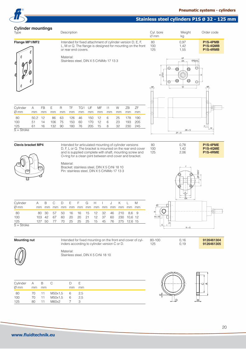
Flange MF1/MF2 IntendedforfixedattachmentofcylinderversionD,E,F,L,MorQ.Theflangeisdesignedformountingonthefrontorrearendcovers.Material:Stainlesssteel,DINX5CrNiMo17133
Cylinder A FB E R TF TG1 UF MF I1 W ZB ZFØmm mm mm mm mm mm mm mm mm mm mm mm mm
80 50,� 1� 86 63 1�6 46 150 1� 6 �5 178 190100 51 14 106 75 150 60 170 1� 6 �3 193 �051�5 61 16 13� 90 180 76 �05 15 8 3� �30 �45S=Stroke
Clevis bracket MP4 IntendedforarticulatedmountingofcylinderversionsD,F,LorQ.Thebracketismountedontherearendcoverandissuppliedcompletewithshaft,mountingscrewandO-ringforacleanjointbetweenendcoverandbracket.Material:Bracket:stainlesssteel,DINX5CrNi1810Pin:stainlesssteel,DINX5CrNiMo17133
Cylinder A B C D E F G H I J K L MØmm mm mm mm mm mm mm mm mm mm mm mm mm mm
80 80 30 57 50 16 16 15 1� 3� 46 �10 8,6 9100 103 4� 67 60 �0 �0 �1 1� 37 60 �30 10,6 1�1�5 1�7 50 77 70 �5 �5 �5 15 45 76 �75 1�,6 15S=Stroke
Mounting nut Intendedforfixedmountingonthefrontendcoverofcyl-indersaccordingtocylinderversionCorD.Material:Stainlesssteel,DINX5CrNi1810
Cylinder A B C D EØmm mm mm mm mm
80 70 11 M50x1,5 6 �,5100 70 11 M50x1,5 6 �,51�5 80 11 M60x� 7 3
80 0,97 P1S-4PMB100 1,4� P1S-4QMB1�5 1,55 P1S-4RMB
D
E
B
C A
EDCØA
J
JØ
F H
9/h7
K + S
ØL
M x 45°
B
G IH
UFØA ØFB(4x)
TF
E R
❑T
G1
MF MF
I1W
ZB + S
ZF + S
80 0,78 P1S-4PME100 1,4� P1S-4QME1�5 �,06 P1S-4RME
80-100 0,16 91264613041�5 0,19 9126461305
www.fluidtechnik.euwww.fluidtechnik.eu
Stainless steel cylinders P1S 32 - 125 mmStainless steel cylinders P1S 32 - 125 mmØØ
Pneumatic systems - cylindersPneumatic systems - cylinders
�1
Cylinder mountingsType Description Cyl.bore Weight Ordercode ∅ mm kg
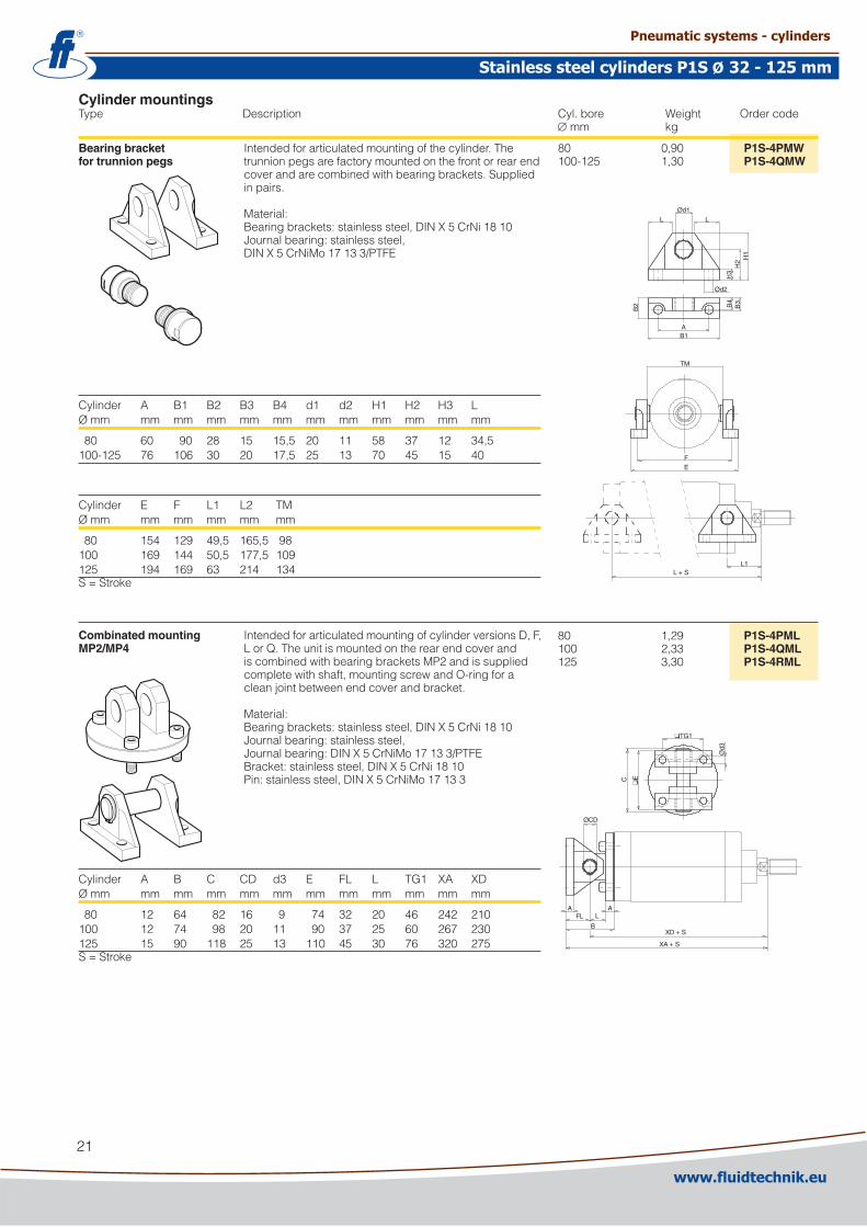
Bearing bracket Intendedforarticulatedmountingofthecylinder.Thefor trunnion pegs trunnionpegsarefactorymountedonthefrontorrearend
coverandarecombinedwithbearingbrackets.Suppliedinpairs.Material:Bearingbrackets:stainlesssteel,DINX5CrNi1810Journalbearing:stainlesssteel,DINX5CrNiMo17133/PTFE
Cylinder A B1 B� B3 B4 d1 d� H1 H� H3 LØmm mm mm mm mm mm mm mm mm mm mm mm
80 60 90 �8 15 15,5 �0 11 58 37 1� 34,5100-1�5 76 106 30 �0 17,5 �5 13 70 45 15 40
Cylinder E F L1 L� TMØmm mm mm mm mm mm
80 154 1�9 49,5 165,598100 169 144 50,5 177,51091�5 194 169 63 �14 134S=Stroke
Combinated mounting IntendedforarticulatedmountingofcylinderversionsD,F,MP2/MP4 LorQ.Theunitismountedontherearendcoverand
iscombinedwithbearingbracketsMP�andissuppliedcompletewithshaft,mountingscrewandO-ringforacleanjointbetweenendcoverandbracket.Material:Bearingbrackets:stainlesssteel,DINX5CrNi1810Journalbearing:stainlesssteel,Journalbearing:DINX5CrNiMo17133/PTFEBracket:stainlesssteel,DINX5CrNi1810Pin:stainlesssteel,DINX5CrNiMo17133
Cylinder A B C CD d3 E FL L TG1 XA XDØmm mm mm mm mm mm mm mm mm mm mm mm
80 1� 64 8� 16 9 74 3� �0 46 �4� �10100 1� 74 98 �0 11 90 37 �5 60 �67 �301�5 15 90 118 �5 13 110 45 30 76 3�0 �75S=Stroke
80 0,90 P1S-4PMW100-1�5 1,30 P1S-4QMW
LØd1
L
Ød2
H3
H2 H
1
B2
AB1
B4
B3
L1L + S
TM
FE
ØCD
AFL L
A
BXD + S
XA + S
❑TG1
C
❑E
Ød3
80 1,�9 P1S-4PML100 �,33 P1S-4QML1�5 3,30 P1S-4RML
www.fluidtechnik.euwww.fluidtechnik.eu
Stainless steel cylinders P1S 32 - 125 mmStainless steel cylinders P1S 32 - 125 mmØØ
Pneumatic systems - cylindersPneumatic systems - cylinders

��
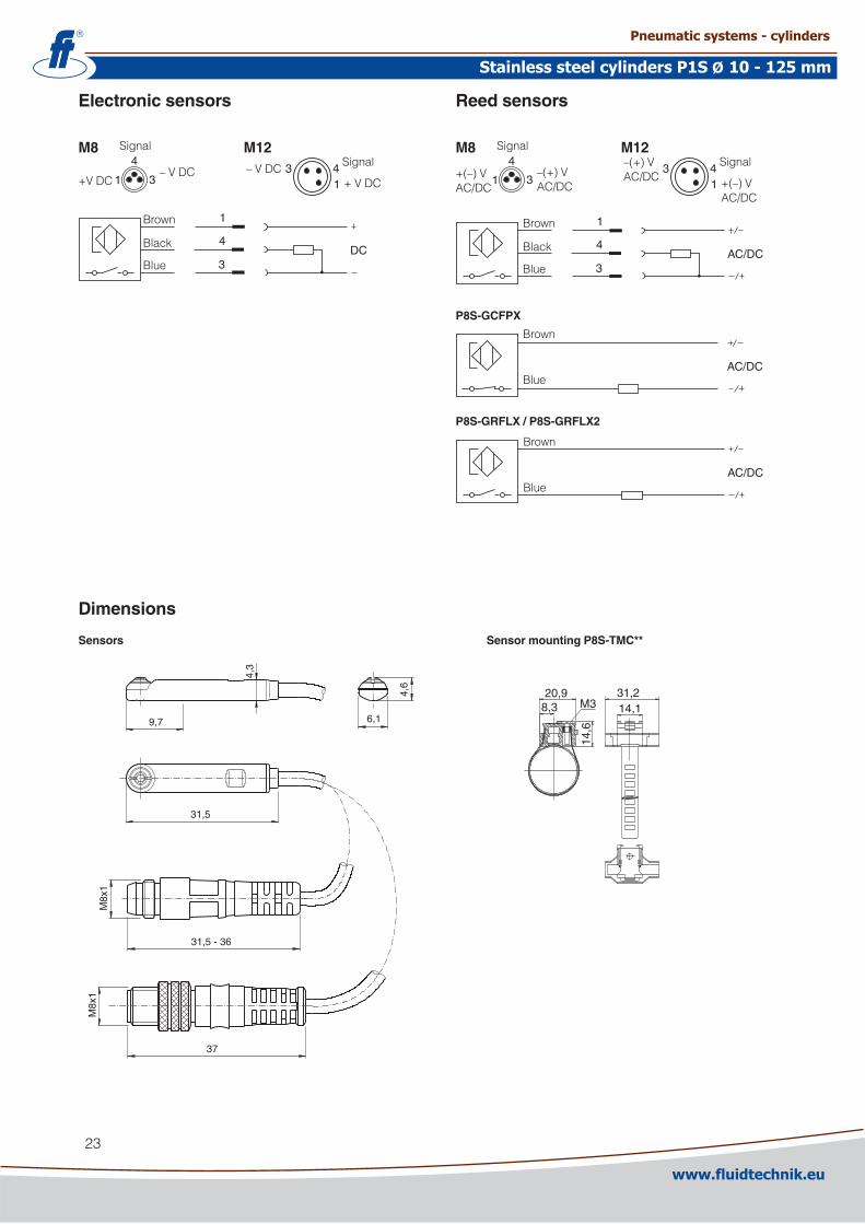
Our global series of sensorsThisseriesofsensorsisalreadybeingusedorwillbeusedinallfuturerangesinourglobalproductprogrammeinvolvingcylinders/actuators.Thesensorshavesmallinstallationdimensionsandeitherfitintothegrooveinthecaseprofileor,asshownhere,arefastenedtothecylinderusingaspecialattachment.Youcanchoosefromelectronicorreedsensorswitharangeofcablelengthsfittedwith8mmorM1�terminals.
Electronic sensors Thenewelectronicsensorsare”SolidState”,i.e.theyhavenomovingpartsatall.Theyareprovidedwithshort-circuitprotec-tionandtransientprotectionasstandard.Thebuilt-inelec-tronicsmakethesensorssuitableforapplicationswithhighonandoffswitchingfrequency,andwhereverylongservicelifeisrequired.
Technical dataDesign GMR(GiantMagneticResistance) magneto-resistivefunctionInstallation SensormountingP8S-TMC01Outputs PNP,normallyopen(alsoavailablein NPNdesign,normallyclosed, onrequest)Voltagerange 10-30VDC 10-18VDC,ATEXsensorRipple max10%Voltagedrop max�,5VLoadcurrent max100mAInternalconsumption max10mAActuatingdistance min9mmHysteresis max1,5mmRepeatabilityaccuracy max0,�mmOn/offswitchingfrequency max5kHzOnswitchingtime max�msOffswitchingtime max�msEncapsulation IP67(EN605�9)Temperaturerange –�5°Cto+75°C –�0°Cto+45°C,ATEXsensorIndication LED,yellowMaterialhousing PA1�Materialscrew StainlesssteelCable PVCorPUR3x0.�5mm�
seeordercoderespectively
Reed sensors Thesensorsarebasedonprovenreedswitches,whichofferreliablefunctioninmanyapplications.Simpleinstallation,aprotectedpositiononthecylinderandclearLEDindicationareimportantadvantagesofthisrangeofsensors.
Technical dataDesign ReedelementMounting SensormountingP8S-TMC01Output Normallyopen,ornormallyclosedVoltagerange 10-30VAC/DCor 10-1�0VAC/DC �4-�30VAC/DCLoadcurrent max500mAfor10-30Vor max100mAfor10-1�0V max30mAfor�4-�30VBreakingpower(resistive) max6W/VAActuatingdistance min9mmHysteresis max1,5mmRepeatabilityaccuracy 0,�mmOn/offswitchingfrequency max400HzOnswitchingtime max1,5msOffswitchingtime max0,5msEncapsulation IP67(EN605�9)Temperaturerange –�5°Cto+75°CIndication LED,yellowMaterialhousing PA1�Materialscrew StainlesssteelCable PVCorPUR3x0.14mm�
seeordercoderespectively
www.fluidtechnik.euwww.fluidtechnik.eu
Pneumatic systems - cylindersPneumatic systems - cylinders
Stainless steel cylinders P1S 10 - 125 mmStainless steel cylinders P1S 10 - 125 mmØØ
�3
Sensors
31,5
37
M8x
1M
8x1
4,3
6,1
4,6
9,7
31,5 - 36
1
4
3DC
Brown
Black
Blue
1
4
3AC/DC
1
4
3+(–)VAC/DC
Signal
–(+)VAC/DC
Brown
Black
Blue
AC/DC
Brown
Blue
P8S-GRFLX / P8S-GRFLX2
143
+(–)VAC/DC
Signal–(+)VAC/DC
M8 M12
1
4
3+VDC
Signal
–VDC143
+VDC
Signal–VDC
M8 M12
Electronic sensors Reed sensors
AC/DC
P8S-GCFPX
Brown
Blue
Dimensions
Sensor mounting P8S-TMC**
20,98,3 M3
14,6
31,214,1
www.fluidtechnik.euwww.fluidtechnik.eu
Pneumatic systems - cylindersPneumatic systems - cylinders
Stainless steel cylinders P1S 10 - 125 mmStainless steel cylinders P1S 10 - 125 mmØØ
�4
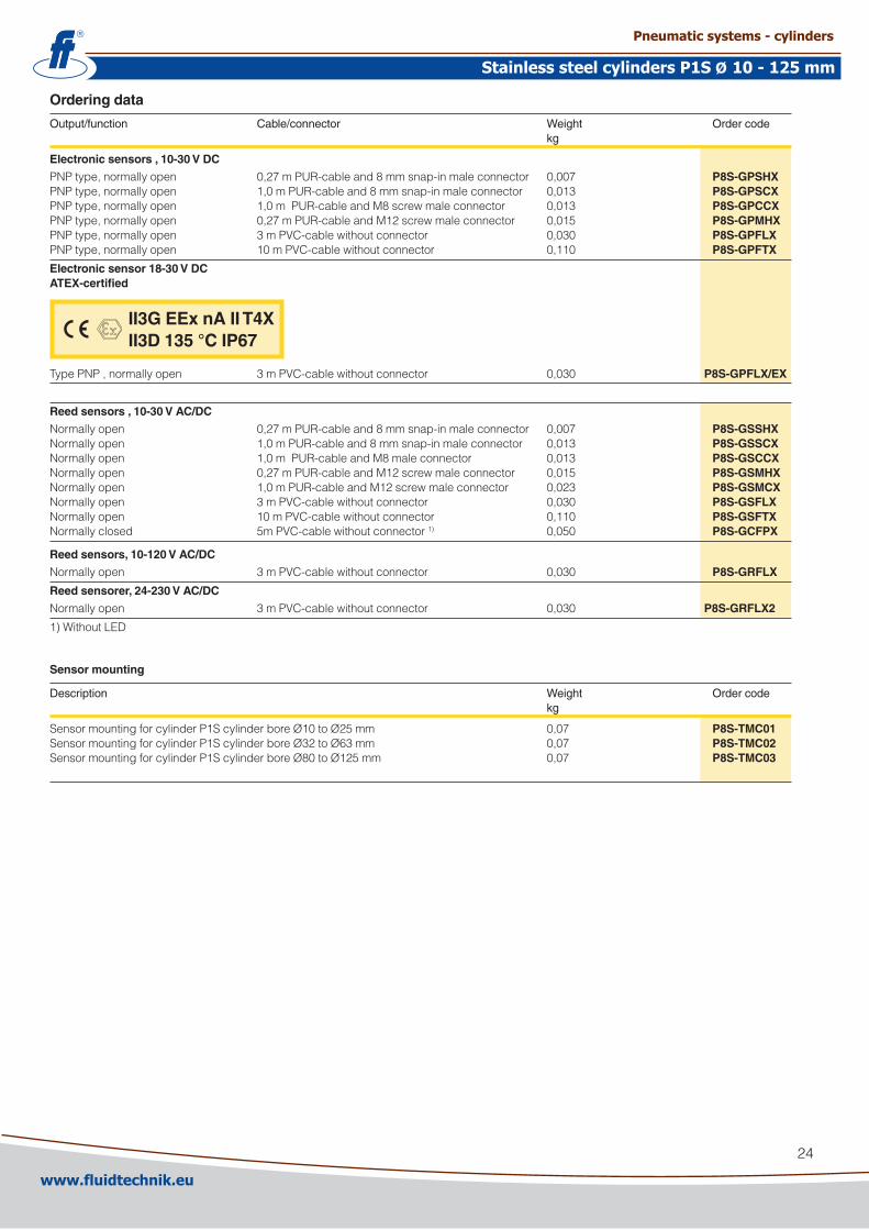
Ordering data
Output/function Cable/connector Weight Order code kg
Electronic sensors , 10-30 V DC
PNPtype,normallyopen 0,�7mPUR-cableand8mmsnap-inmaleconnector 0,007 P8S-GPSHXPNPtype,normallyopen 1,0mPUR-cableand8mmsnap-inmaleconnector 0,013 P8S-GPSCXPNPtype,normallyopen 1,0mPUR-cableandM8screwmaleconnector 0,013 P8S-GPCCXPNPtype,normallyopen 0,�7mPUR-cableandM1�screwmaleconnector 0,015 P8S-GPMHXPNPtype,normallyopen 3mPVC-cablewithoutconnector 0,030 P8S-GPFLXPNPtype,normallyopen 10mPVC-cablewithoutconnector 0,110 P8S-GPFTX
Electronic sensor 18-30 V DC ATEX-certified
TypePNP,normallyopen 3mPVC-cablewithoutconnector 0,030 P8S-GPFLX/EX
Reed sensors , 10-30 V AC/DC
Normallyopen 0,�7mPUR-cableand8mmsnap-inmaleconnector 0,007 P8S-GSSHXNormallyopen 1,0mPUR-cableand8mmsnap-inmaleconnector 0,013 P8S-GSSCXNormallyopen 1,0mPUR-cableandM8maleconnector 0,013 P8S-GSCCXNormallyopen 0,�7mPUR-cableandM1�screwmaleconnector 0,015 P8S-GSMHXNormallyopen 1,0mPUR-cableandM1�screwmaleconnector 0,0�3 P8S-GSMCXNormallyopen 3mPVC-cablewithoutconnector 0,030 P8S-GSFLXNormallyopen 10mPVC-cablewithoutconnector 0,110 P8S-GSFTXNormallyclosed 5mPVC-cablewithoutconnector1) 0,050 P8S-GCFPX
Reed sensors, 10-120 V AC/DC
Normallyopen 3mPVC-cablewithoutconnector 0,030 P8S-GRFLX
Reed sensorer, 24-230 V AC/DC
Normallyopen 3mPVC-cablewithoutconnector 0,030 P8S-GRFLX2
1)WithoutLED
Sensor mounting
Description Weight Order code kg
SensormountingforcylinderP1ScylinderboreØ10toØ�5mm 0,07 P8S-TMC01SensormountingforcylinderP1ScylinderboreØ3�toØ63mm 0,07 P8S-TMC02SensormountingforcylinderP1ScylinderboreØ80toØ1�5mm 0,07 P8S-TMC03
II3G EEx nA II T4X II3D 135 °C IP67
www.fluidtechnik.euwww.fluidtechnik.eu
Pneumatic systems - cylindersPneumatic systems - cylinders
Stainless steel cylinders P1S 10 - 125 mmStainless steel cylinders P1S 10 - 125 mmØØ

�5
Sensors for special applicationsSensorsforapplicationswheretheshortinstallationlengthandthe90degreecableoutletareimportantfactors.Thistypeofsensorisangoodalternativeifacylinderhasashortstrokeortightinstallation,andinstallationiseasierthanourglobalseriesofsensors.
Technical dataDesign HallelementOutput PNPresp.NPN,N.O.Voltagerange 10-30VDCMaxpermissibleripple 10%Maxvoltagedrop ≤0,5Vat100mAMaxloadcurrent,P1A-�XMK,LK 150mAP1A-�XHK,EK,JH,FH 100mAMaxbreakingpower(resistive) 6WInternalconsumption <30mAat30VMinactuatingdistance 5mmHysteresis 1,1-1,3mmRepeatabilityaccuracy ±0,1mmMaxon/offswitchingfrequency 1kHzMaxon/offswitchingtime 0,8/3,0µsEncapsulation,P1A-�XJH,FH IP65Encapsulation,P1A-�XHK,EK,MK,LK IP67Temperaturerange –10°Cto+60°CIndication LEDShockresistance 40gMaterial,housing Polyamid11Material,mould EpoxyCable PVC3x0,15mm�
Cableincl.femalepartconnector PVC3x0,15mm�
Connector Diam.8mmsnaponMounting MountingyokeMaterial,mounting Acetal/StainlesssteelMaterial,screw Stainlesssteel
Ordering data
Output Cable Weight Order code length kg
Electronic sensors
PNP,N.O. �m 0,040 P1A-2XMKNPN,N.O. �m 0,040 P1A-2XLK
Mountngs for sensors
ForcylinderØ10 0,005 P1A-2CCCForcylinderØ1� 0,005 P1A-2DCCForcylinderØ16 0,008 P1A-2FCCForcylinderØ�0 0,008 P1A-2HCCForcylinderØ�5 0,010 P1A-2JCC
Black
Red
White White
Black
Red
P1A-2XMK P1A-2XLK
LED
14
12 19
3 x 0,15 mm, 2 m
DimensionsP1A-2XMK and P1A-2XLK
Electronic sensor symbol
www.fluidtechnik.euwww.fluidtechnik.eu
Pneumatic systems - cylindersPneumatic systems - cylinders
Stainless steel cylinders P1S 10 - 125 mmStainless steel cylinders P1S 10 - 125 mmØØ

�6
Asaccessoriesthesystemcomprisesalargenumberofdifferentca-blesinordertomeetallrequirementsthatmayariseandtomaketheinstallationsimple,fastandreliable. Cableswithmoulded8mmsnap-inroundcontactsinbothends.Thecablesareavailableintwotypes,onewithastraightmaleandfemaleconnectorsrespectively,andonewithastraight3-polemaleconnectorinoneendandanangled3-polefemaleconnectorintheotherend.
Technical dataContactsMoulded8mmsnap-inmale/femalecontacts.Enclosure IP67
CableConductor 3x0,�5mm�(3�x0,10mm�)Sheath PVC/PURColour Black
Designation Weight Order code kg
Cablewithstraightcontacts,0,�m 0,0� 9121717014Cablewithstraightcontacts,0,3m 0,0� 9121717015Cablewithstraightcontacts,0,5m 0,03 9121717016Cablewithstraightcontacts,1,0m 0,03 9121717017Cablewithstraightcontacts,�,0m 0,05 9121717018Cablewithstraightcontacts,3,0m 0,07 9121717019Cablewithstraightcontacts,5,0m 0,1� 9121717020Cablewithstraightcontacts,10m 0,�3 9121717021
Designation Weight Order code kg
Cablewithstraightandangledconnectors,0,�m0,0� 9121717022Cablewithstraightandangledconnectors,0,3m0,0� 9121717023Cablewithstraightandangledconnectors,0,5m0,03 9121717024Cablewithstraightandangledconnectors,1,0m0,03 9121717025Cablewithstraightandangledconnectors,�,0m0,05 9121717026Cablewithstraightandangledconnectors,3,0m0,07 9121717027Cablewithstraightandangledconnectors,5,0m0,1� 9121717028Cablewithstraightandangledconnectors,10m 0,�3 9121717029
Type of cable Cable/connector Weight Order code kg
Cables for sensors, complete with one female connector
Cable,FlexPVC 3m,8mmSnap-inconnector 0,07 9126344341Cable,FlexPVC 10m,8mmSnap-inconnector 0,�1 9126344342Cable,SuperFlexPVC 3m,8mmSnap-inconnector 0,07 9126344343Cable,SuperFlexPVC 10m,8mmSnap-inconnector 0,�1 9126344344Cable,Polyurethane 3m,8mmSnap-inconnector 0,01 9126344345Cable,Polyurethane 10m,8mmSnap-inconnector 0,�0 9126344346Cable,Polyurethane 5m,M1�screwconnector 0,07 9126344348Cable,Polyurethane 10m,M1�screwconnector 0,�0 9126344349
Male connectors for connecting cablesCableconnectorsforproducingyourownconnectingcables.Theconnectorscanbequicklyattachedtothecablewithoutspecialtools.Onlytheoutersheathofthecableisremoved.TheconnectorsareavailableforM8andM1�screwconnectorsandmeetprotectionclassIP65.
Connector Weight Order code kg
M8screwconnector 0,017 P8SCS0803JM1�screwconnector 0,0�� P8SCS1204J
Connecting cables with one connectorThecableshaveanintegralsnap-infemaleconnector.
Cableswithstraight3-polemaleandfemaleconnectorsrespectively. Cableswithastraight3-polemaleconnectorinoneendandanan-gled3-polefemaleconnectorintheotherend.
Ready to use connecting cables with connectors at each end
www.fluidtechnik.euwww.fluidtechnik.eu
Pneumatic systems - cylindersPneumatic systems - cylinders
Stainless steel cylinders P1S 10 - 125 mmStainless steel cylinders P1S 10 - 125 mmØØ

�7
Connection block Valvetronic 110TheValvetronic110isaconnectionblockthatcanbeusedforcollectingsignalsfromsensorsatvariouspointsonamachineandconnectingthemtothecontrolsystemviaamulticorecable.Valvetronic110canalsobeusedforcentralconnectionofthemulti-corecabletotheoutputsofacontrolsystem,andcanbelaidtoamachinewheretheoutputsignalscanbecon-nected.Theconnectionblockhasten8mmsnap-incircularconnectorsandamulti-corecablewhichisavailableinlengthsof3or10m.Theconnectionsontheblockarenumberedfrom1to10.Blankingplugsareavailableforunusedconnections,aslabelsformarkingtheconnectionsofeachblock.
18,7
12,5
825 12
9,2 20,5
L
30,5
8575
M3
6 7 8 9 10
1 2 3 4 5
3 3 3 3 3
2 2 2 2 2
1 1 1 1 1
3 3 3 3 3
2 2 2 2 2
1 1 1 1 1
A
5 43 21
67 89 10B
Technical dataConnections:Ten3-polenumbered8mmroundsnap-infemalecontacts Inputblock Pin1 Common,+�4VDC Pin� Inputsignal Pin3 Common,0V
Outputblock Pin1 Common,GND Pin� Outputsignal Pin3 Common,0V
Electrical data:Voltage �4VDC(max.60VAC/75VDC)Insulationgroup accordingtoDIN0110classCLoad max.1Aperconnection totalmax.3A
Cable:Length 3mor10mTypeofcable LifYY11YConductor 1�Area 0.34mm�
Colourmarking AccordingtoDIN47100
32
1
32
1
Mechanical dataEnclosure IP67,DIN40050withfittedcontactsand/or blankingplugs.Temperature –�0°Cto+70°C
MaterialBody PA6,6VDaccordingtoUL94Contactholder PBTPSnap-inring LDPEMouldingmass EpoxySeal NBRScrews Platedsteel
Industrial durabilityGoodchemicalandoilresistance.Testsshouldbeperformedinaggressiveenvironments.
Ordering data
Designation Weight Order code kg
ConnectionblockValvetronic110with3mcable 0,3� 9121719001 ConnectionblockValvetronic110with10mcable 0,95 9121719002
Blankingplugs(packof10) 0,0� 9121719003 Useblankingplugstocloseunusedconnections.
Labels(packof10) 0,0� 9121719004 Whitelabelstoinsertingroovesonthesideoftheconnection
Dimensions and wiring diagrams
Conductor Colour Input Output
1 Pink Signal 1 Signal 1 2 Grey Signal 2 Signal 2 3 Yellow Signal 3 Signal 3 4 Green Signal 4 Signal 4 5 White Signal 5 Signal 5 6 Red Signal 6 Signal 6 7 Black Signal 7 Signal 7 8 Violet Signal 8 Signal 8 9 Grey-Pink Signal 9 Signal 9 10 Red-Blue Signal 10 Signal 10 A Blue 0 V 0 V B Brown +24 V PE
www.fluidtechnik.euwww.fluidtechnik.eu
Pneumatic systems - cylindersPneumatic systems - cylinders
Stainless steel cylinders P1S 10 - 125 mmStainless steel cylinders P1S 10 - 125 mmØØ

�8
Grease
Version Weight Order code
StandardandLowtemperature 30g 9127394541
Hightemperature 30g 9127394521
Seal kits for P1S cylinders
Completesealkitsconsistingof:PistonsealsCushioningsealsPistonrodbearingPistonrodsealScraperringO-rings
Materialspecification,seepages16and17.
Standard temperature versions
Cylinder designation Order code
P1S-•03�MS 9121659195
P1S-•040MS 9121659196
P1S-•050MS 9121659197
P1S-•063MS 9121659198
P1S-•080MS 9121718905
P1S-•100MS 9121718906
P1S-•1�5MS 9121718907
High temperature versions
Cylinder designation Order code
P1S-•03�MF 9121720595
P1S-•040MF 9121720596
P1S-•050MF 9121720597
P1S-•063MF 9121720598
P1S-•080MF 9121718925
P1S-•100MF 9121718926
P1S-•1�5MF 9121718927
Low temperature versions
Cylinder designation Order code
P1S-•080ML 9121718935
P1S-•100ML 9121718936
P1S-•1�5ML 9121718937
Standard temperature with Through rod
Cylinder designation Order code
P1S-•080FS 9121718955
P1S-•100FS 9121718956
P1S-•1�5FS 9121718957
Standard temperature with stainless steel scraper ring
Cylinder designation Order code
P1S-•080MQ 9121718915
P1S-•100MQ 9121718916
P1S-•1�5MQ 9121718917
www.fluidtechnik.euwww.fluidtechnik.eu
Pneumatic systems - cylindersPneumatic systems - cylinders
Stainless steel cylinders P1S 10 - 125 mmStainless steel cylinders P1S 10 - 125 mmØØ

�9
www.fluidtechnik.euwww.fluidtechnik.eu
Pneumatic systems - cylindersPneumatic systems - cylinders
Stainless steel cylinders P1S 10 - 125 mmStainless steel cylinders P1S 10 - 125 mmØØ

30
www.fluidtechnik.euwww.fluidtechnik.eu
Pneumatic systems - cylindersPneumatic systems - cylinders
Stainless steel cylinders P1S 10 - 125 mmStainless steel cylinders P1S 10 - 125 mmØØ

www.fluidtechnik.euwww.fluidtechnik.eu
Pneumatic systems - cylindersPneumatic systems - cylinders
Stainless steel cylinders P1S 10 - 125 mmStainless steel cylinders P1S 10 - 125 mmØØ

FLUIDTECHNIK BOHEMIA, s. r. o., Olomoucká 87, 627 00 BRNO, tel.: +420 548 213 233-5, +420 548 426 811, fax: +420 548 213 238POLIÈKA – Družstevní 422, 572 01, tel.: 461 722 319, fax: 461 721 044 • NOVÉ MÌSTO NAD METUJÍ – Vrchoviny 29, 549 01,
tel./fax: 491 472 844, tel.: 491 472 328 • OPAVA – Hradecká 668/1, 746 01, tel.: 553 770 911, fax: 553 770 912LOUNY – Vladimírská 2457, 440 01, tel./fax: 415 658 703 • PLZEÒ – Brojova 16, 326 00, tel.: 378 121 340, fax: 378 121 341
E-mail: [email protected] • www.fluidtechnik.eu NON STOP linka technické podpory: 548 426 832
• www.parker-origa.cz
Catalogue no: PDE2535TCUK-ul.XM 01/2008XX