stability of secure routing protocol in ad hoc wireless
TRANSCRIPT

Stability of Secure Routing Protocol in
Ad hoc wireless Network
Ph.D. Thesis
Saud Rugeish Alotaibi
This thesis is submitted in partial fulfilment of the
requirement for the Doctor of Philosophy
Awarded by
Faculty of Technology
De Montfort University
United Kingdom, England
2010

Declaration
I
Declaration
I declare that the work described in this thesis is original work undertaken by me for the degree
of Doctor of Philosophy, at the Software Technology Research Laboratory, Faculty of
Technology, at De Montfort University, United Kingdom. No part of the material described in
this thesis has been submitted for the award of any other degree or qualification in this or any
other university or college of advanced education.

Dedication
Dedication
TToo mmyy ppaarreennttss
WWhhoo ddeesseerrvvee ssppeecciiaall rreeccooggnniittiioonn
ffoorr tthheeiirr eennddlleessss ssuuppppoorrtt aallll tthhee wwaayy tthhrroouugghh mmyy lliiffee..
To my Father- and Mother-in-law
for their encouragements and their endless love
To my lovely and patient wife, ABEER..
ffoorr hheerr eennccoouurraaggeemmeenntt aanndd ggrreeaatt ssuuppppoorrtt
To my lovely daughters, Joud, Jana and Jinan
Abstract
III
Abstract
Ad hoc wireless networking is a new approach to wireless communication with potential applications in
very unpredictable and dynamic environments. In contrast to wired and cellular networks, an ad hoc
wireless network does not depend on any established infrastructure or centralised administration such as a
base station. It is an autonomous system of wireless mobile nodes that move freely and randomly,
organising themselves arbitrarily. Therefore, its network topology is dynamic in nature and may change
rapidly and unpredictably. Hence, the intercommunications among nodes will change continuously. Such
networks have no infrastructure for achieving end-to-end routing of packets. The nodes communicate
with each other without the intervention of a centralized administration; thus each acts both as a router
and as a host.
The security of ad hoc wireless networks is becoming an increasingly complex issue. Many applications
today, especially military and emergency ones, are based upon ad hoc wireless networks, where security
requirements are harder to enforce than in traditional networks. Securing routing creates particular
difficulties, since these networks have neither centrally administrated secure routers nor strict policies of
use. The network topology is rapidly changing due to nodes in the networks being highly mobile, thus
creating the presence or absence of links. Therefore, routing is especially difficult to accomplish securely,
robustly and efficiently at the same time. Security requirements such as authentication, non-repudiation,
data integrity and confidentiality, which would otherwise be provided by a central server, must be enabled
and provided by all nodes.
The contributions of this research are threefold. First, it offers a new routing approach to ad hoc wireless
network protocols: the Enhanced Heading-direction Angle Routing Protocol (EHARP), which is an
enhancement of HARP based on an on-demand routing scheme. We have added important features to
overcome its disadvantages and improve its performance, providing the stability and availability required
to guarantee the selection of the best path. Each node in the network is able to classify its neighbouring
nodes according to their heading directions into four different zone-direction groups. The zone direction
is reduced until the node can select the strongest and most stable link and so increase availability in the
network. Each node in the network has a counter for the stability of link (SL) to its neighbouring nodes,
which indicates which nodes are active in the network, improving the performance of the network and
increasing the likelihood of selecting the optimal path. EHARP is based on the time and
acknowledgement message in order to guarantee the selection of the path and link stability.

Abstract
IV
The second contribution is to present a new Secure Enhanced Heading-direction Angle Routing Protocol
(SEHARP) for ad hoc networks based on the integration of security mechanisms that could be applied to
the EHARP routing protocol. It proposes a novel secure routing protocol to improve the security level in
ad hoc networks, based on key management and a secure node-to-node path, which protects data to
satisfy our security requirements: the detection of malicious nodes, authentication, authorisation,
confidentiality, availability, data integrity and a guarantee of secure correct route discovery. SEHARP
works as a group and has three stages:
- Distribution of keys and certificate stage.
- Secure path stage.
- Secure routing protocol stage.
Thirdly, we present a new approach to security of access in hostile environments based on the history and
relationships among the nodes and on digital operation certificates. We also propose an access activity
diagram which explains the steps taken by a node. Security depends on access to the history of each unit,
which is used to calculate the cooperative values of each node in the environment. The calculated
cooperative values are then used by the relationship estimator to determine the status of the nodes. Each
node should be capable of making its own security decisions based on cooperation with other peer nodes.
The EHARP and SEHARP protocols are both evaluated using the NS-2 network simulator. The NS-2-
based evaluation tests the two proposed protocols in real network environments and measures their
communication costs using other evaluation metrics such as the data packet delivery ratio, the efficiency
of data packet delivery, the average end-to-end-delay of data packets and overheads. The results of the
evaluation study shows and prove that EHARP is a protocol that provides a high level of availability,
scalability, flexibility and efficiently for Ad hoc Wireless Network. Also the evaluation study shows and
proves that SEHARP is fully security protocol that provides a high level of secure, available, scalable,
flexible and efficient for Ad hoc Wireless Network.

Acknowledgments
V
Acknowledgments
First and foremost, I am thankful to Almighty ALLAH for all his bounties and blessings, for giving me
the ability to complete this research, without which none of my work would have been done.
Studying at University of De Montfort and particularly at the STRL was the most rewarding experience I
have ever had. For me, this is certainly related to the high standard of the facilities offered to students, the
friendly atmosphere among the research students, and above all the excellence of supervision. For this
reason I would like to express my deepest appreciation and lasting gratitude to Professor Hussein Zedan
head of the STRL, for his guidance, ideas, invaluable directions and support throughout my research
study. Without his contributions, this research would not have been possible. I am deeply indebted to him
for his insights and suggestions to the research topic and for invaluable supervision at various stages of
my work. He has helped me in many ways and has developed my academic thinking, problem solving
which will be very helpful in my future work and research. I feel extremely lucky to have had as my
supervisor one who is always dedicated to the success of his students.
My thanks and appreciation also go to to my supervisor, Dr. Francois Siewe, for his valuable comments,
constructive criticism, academic support, insightful comments, guidance and suggestions, without which
this thesis could not have been produced in the present form.
I would also like to express my thanks to my family especially my parents, and my brothers and sister
who have always supported me during my studies and provided advice and encouragement throughout my
research. I would also like to thank my wife and my daughters for being there for me and supporting me
in my decisions; they truly share in this achievement. Thank you for your patience, love and dedication.

Acknowledgments
VI
I would also like to express my great thanks to Dr Mohammad Taye and Dr Ali Al Bayatti for their
assistance and support during the whole duration of my research.
Last but not least, my thanks go to all my friends and the staff of the STRL research group, especially Mrs
Lindys, Mrs Lynn, Abddullah Bajahzar, Mohammed Al-Sammarraie, Nasser Alwan, Ali Al-Qhatani and
Khalid Al-Drawiesh for their help. Being with them made working in the lab very enjoyable.

PUBLICATINS
VII
PUBLICATIONS
1- Al-Otaibi S, Siewe F, “Architecture of EHARP Routing Protocols in Ad Hoc Wireless Networks”,
IEEE International conference on intelligent network and collaborative system (INCoS 2009).
2- Al-Otaibi S, Siewe F, “Secure Routing Protocol Base on Secure Path in Ad hoc Wireless Networks”,
IEEE International Forum on Computer Science-Technology and Applications (IFCSTA 2009).
3- Al-Otaibi S, Siewe F, “Security of access in hostile environments based on the history of nodes in ad
hoc networks”, IEEE the First Asian Himalayas International Conference on Internet (AH-ICI2009).
4- Al-Otaibi S, Siewe F, “Architecture of Stability Routing Protocols in Ad Hoc Wireless Networks”,
IEEE International Forum on Computer Science-Technology and Applications (IFCSTA 2009).
Table of Contents
IX
Table of Contents
DECLARATION ------------------------------------------------------------------------------------------------------------------------ I
DEDICATION ------------------------------------------------------------------------------------------------------------------------- II
ABSTRACT --------------------------------------------------------------------------------------------------------------------------- III
ACKNOWLEDGMENTS ------------------------------------------------------------------------------------------------------------ V
PUBLICATIONS -------------------------------------------------------------------------------------------------------------------- VII
TABLE OF CONTENTS ------------------------------------------------------------------------------------------------------------- IX
LIST OF FIGURES ------------------------------------------------------------------------------------------------------------------- IX
LIST OF TABLES --------------------------------------------------------------------------------------------------------------------- IX
LIST OF ABBREVIATIONS --------------------------------------------------------------------------------------------------------- X
CHAPTER 1 --------------------------------------------------------------------------------------------------------------------------- 1
INTRODUCTION --------------------------------------------------------------------------------------------------------------------- 1
1.1 RESEARCH MOTIVATION ------------------------------------------------------------------------------------------------------ 1
1.2 PROBLEM FORMULATION ----------------------------------------------------------------------------------------------------- 2
1.3 CONTRIBUTIONS --------------------------------------------------------------------------------------------------------------- 3
1.3.1 Enhanced Heading Direction Angle Routing Protocol ----------------------------------------------------- 3
1.3.2 Secure Enhanced Heading-direction Angle Routing Protocol -------------------------------------------- 4
1.3.3 Secure Ad hoc Environment -------------------------------------------------------------------------------------- 5
1.3.4 Evaluation ------------------------------------------------------------------------------------------------------------- 6
1.4 THESIS ORGANISATION -------------------------------------------------------------------------------------------------------- 6
CHAPTER 2 --------------------------------------------------------------------------------------------------------------------------- 8
STATE OF THE ART OF AD HOC WIRELESS NETWORKS ------------------------------------------------------------------ 8
2.1 INTRODUCTION ----------------------------------------------------------------------------------------------------------------- 8
2.2 AD HOC WIRELESS NETWORKS ----------------------------------------------------------------------------------------------- 9
2.2.1 Characteristics of Ad Hoc Wireless Networks ---------------------------------------------------------------10
2.2.2 Applications of Ad Hoc Wireless Networks ------------------------------------------------------------------10
2.2.3 Challenges to Ad Hoc Wireless Networks --------------------------------------------------------------------11
2.3 NETWORK SECURITY ----------------------------------------------------------------------------------------------------------12
2.3.1 Security Requirements --------------------------------------------------------------------------------------------13
2.3.2 Security Attacks -----------------------------------------------------------------------------------------------------14
2.3.3 Cryptography --------------------------------------------------------------------------------------------------------17 2.3.3.1 Symmetric Key Algorithms -------------------------------------------------------------------------------------------- 17 2.3.3.2 Asymmetric / Public Key Encryption ------------------------------------------------------------------------------- 18 2.3.3.3 Digital Signatures ------------------------------------------------------------------------------------------------------- 19 2.3.3.4 Digital Certificates ------------------------------------------------------------------------------------------------------ 20 2.3.3.5 Public Key Infrastructure ---------------------------------------------------------------------------------------------- 21
2.4 SECURITY IN AD HOC WIRELESS NETWORKS --------------------------------------------------------------------------------24
2.4.1 Security Challenges ------------------------------------------------------------------------------------------------24
2.4.2 Key Management --------------------------------------------------------------------------------------------------25 2.4.2.1 Trusted Third Party ----------------------------------------------------------------------------------------------------- 26 2.4.2.2 Cluster-based Approach to Ad Hoc Wireless Networks -------------------------------------------------------- 27

Table of Contents
X
2.5 AD HOC WIRELESS NETWORK LAYERS---------------------------------------------------------------------------------------28
2. 6 SUMMARY --------------------------------------------------------------------------------------------------------------------30
CHAPTER 3 --------------------------------------------------------------------------------------------------------------------------31
CRITICAL REVIEW OF ROUTING PROTOCOLS AND SECURE ROUTING IN AD HOC WIRELESS NETWORKS
------------------------------------------------------------------------------------------------------------------------------------------31
3.1 INTRODUCTION ----------------------------------------------------------------------------------------------------------------31
3.2 CHALLENGES IN ROUTING ----------------------------------------------------------------------------------------------------31
3.3 REQUIREMENTS OF ROUTING PROTOCOLS FOR AD HOC WIRELESS NETWORKS ------------------------------------------32
3.4 CLASSIFICATIONS OF CURRENT ROUTING PROTOCOLS ---------------------------------------------------------------------33
3.4.1 Proactive Routing Protocols -------------------------------------------------------------------------------------34 3.4.1.1 Destination-Sequenced Distance-Vector -------------------------------------------------------------------------- 34 3.4.1.2 Wireless Routing Protocol -------------------------------------------------------------------------------------------- 36 3.4.1.3 Cluster-head Gateway Switch Routing ----------------------------------------------------------------------------- 37
3.4.2 Reactive Routing Protocols --------------------------------------------------------------------------------------38 3.4.2.1 Ad hoc On-demand Distance Vector ------------------------------------------------------------------------------- 39 3.4.2.2 Heading-directional Angle Routing Protocol --------------------------------------------------------------------- 40 3.4.2.3 Dynamic Source Routing Protocol ---------------------------------------------------------------------------------- 41 3.4.2.4 Associatively-Based Routing Protocol ------------------------------------------------------------------------------ 42 3.4.2.5 Signal Stability-Based Adaptive Routing Protocol --------------------------------------------------------------- 43
3.4.3 Hybrid Routing Protocols -----------------------------------------------------------------------------------------44 3.4.3.1 Zone Routing Protocol ------------------------------------------------------------------------------------------------- 44
3.5 SECURE ROUTING IN AD HOC WIRELESS NETWORKS-----------------------------------------------------------------------46
3.5.1 Proactive RSA --------------------------------------------------------------------------------------------------------47
3.5.2 Security-aware Ad Hoc Routing Protocol --------------------------------------------------------------------48
3.5.3 Authenticated Routing Protocol --------------------------------------------------------------------------------48
3.5.4 Secure AODV --------------------------------------------------------------------------------------------------------49
3.5.5 Secure Efficient Ad hoc Distance Vector ----------------------------------------------------------------------49
3.6 SUMMARY ---------------------------------------------------------------------------------------------------------------------51
CHAPTER 4 --------------------------------------------------------------------------------------------------------------------------52
ENHANCED HEADING DIRECTION ROUTING PROTOCOLS AND MODELLING ------------------------------------52
4.1 INTRODUCTION ----------------------------------------------------------------------------------------------------------------52
4.2 RESEARCH METHODOLOGY --------------------------------------------------------------------------------------------------53
4.2.1 Simulation Environment ------------------------------------------------------------------------------------------54
4.3 THE KEY IDEA OF HEADING DIRECTION --------------------------------------------------------------------------------------57
4.4 PRINCIPLE OF THE HEADING DIRECTION MECHANISM ---------------------------------------------------------------------59
4.4.1 Categorization of Nodes ------------------------------------------------------------------------------------------59
4.4.2 Downstream Node Selection ------------------------------------------------------------------------------------60
4.4.3 Route Records List--------------------------------------------------------------------------------------------------61
4.5 MODELLING AD HOC WIRELESS NETWORKS --------------------------------------------------------------------------------62
4.5.1 Definition of the System Model ---------------------------------------------------------------------------------62
4.5.2 Assumptions ---------------------------------------------------------------------------------------------------------62
4.5.3 Models ----------------------------------------------------------------------------------------------------------------63 4.5.3.1 Network Model ---------------------------------------------------------------------------------------------------------- 63 4.5.3.2 Mobility Model ---------------------------------------------------------------------------------------------------------- 64 4.5.3.3 Traffic Model ------------------------------------------------------------------------------------------------------------- 65
4.5.4 General System Model --------------------------------------------------------------------------------------------65 4.5.4.1 Message Formats ------------------------------------------------------------------------------------------------------- 65
4.5.4.1.1 Route Records List Format ------------------------------------------------------------------------------------- 66

Table of Contents
XI
4.5.4.1.2 Route Request Message Format------------------------------------------------------------------------------ 66 4.5.4.1.3 Route Reply Message Format --------------------------------------------------------------------------------- 67 4.5.4.1.4 Route Error Message Format ---------------------------------------------------------------------------------- 68 4.5.4.1.5 Hello Message Format ------------------------------------------------------------------------------------------ 69
4.5.4.2 Table Formats ------------------------------------------------------------------------------------------------------------ 70 4.5.4.2.1 Routing Table Format ------------------------------------------------------------------------------------------- 70 4.5.4.2.2 Neighbours Table Format -------------------------------------------------------------------------------------- 71
4.5.5 Route Establishment ----------------------------------------------------------------------------------------------72 4.5.5.1 Route Requests ---------------------------------------------------------------------------------------------------------- 73 4.5.5.2 Route Replies ------------------------------------------------------------------------------------------------------------ 74 4.5.5.3 Route Errors -------------------------------------------------------------------------------------------------------------- 74
4.6 SUMMARY ---------------------------------------------------------------------------------------------------------------------76
CHAPTER 5 --------------------------------------------------------------------------------------------------------------------------77
ALGORITHM AND ANALYSING OF EHARP PROTOCOL ------------------------------------------------------------------77
5.1 INTRODUCTION ----------------------------------------------------------------------------------------------------------------77
5.2 ENHANCED HEADING-DIRECTION ANGLE ROUTING PROTOCOL------------------------------------------------------------78
5.2.1 EHARP Architecture ------------------------------------------------------------------------------------------------78
5.2.2 Route Discovery -----------------------------------------------------------------------------------------------------79 5.2.2.1 Route Discovery at the Source Node ------------------------------------------------------------------------------- 79 5.2.2.2 Route Discovery at Intermediate/ Relay Nodes ----------------------------------------------------------------- 82 5.2.2.3 Route Reply --------------------------------------------------------------------------------------------------------------- 85
5.2.3 Route Maintenance and Local Repair-------------------------------------------------------------------------86
5.3 FORMAL MODEL OF EHARP -------------------------------------------------------------------------------------------------86
5.3.1 Overview of Interval Temporal Logic (ITL) -------------------------------------------------------------------87 5.3.1.1 Syntax and Informal Semantics -------------------------------------------------------------------------------------- 87 5.3.1.2 Derived Constructs ----------------------------------------------------------------------------------------------------- 88
5.3.2 A formal Specification of EHARP Protocol ------------------------------------------------------------------88 5.3.2.1 Static Variables ---------------------------------------------------------------------------------------------------------- 89 5.3.2.2 State Variables ----------------------------------------------------------------------------------------------------------- 89 5.3.2.3 Memory Variables ------------------------------------------------------------------------------------------------------ 89 5.3.2.4 Formal Specification of EHARP -------------------------------------------------------------------------------------- 90
5.3.2.4.1 System Initialisation: Init () ------------------------------------------------------------------------------------ 91 5.3.2.4.2 System Termination: Terminate () --------------------------------------------------------------------------- 91 5.3.2.4.3 Specification of Nodes: Node (i) ------------------------------------------------------------------------------ 91 5.3.2.4.4 The source node performs: ------------------------------------------------------------------------------------ 92 5.3.2.4.5 The intermediate nodes perform:---------------------------------------------------------------------------- 93
5.4 SIMULATION METHODOLOGY AND MODEL ---------------------------------------------------------------------------------94
5.4.1 Simulation Environment ------------------------------------------------------------------------------------------94
5.4.2 Parameter Values --------------------------------------------------------------------------------------------------95
5.5 SUMMARY ---------------------------------------------------------------------------------------------------------------------97
CHAPTER 6 --------------------------------------------------------------------------------------------------------------------------98
SECURE ENHANCED HEADING DIRECTION ANGLE ROUTING PROTOCOL (SEHARP) ---------------------------98
6.1 INTRODUCTION ----------------------------------------------------------------------------------------------------------------98
6.2 OUR SECURITY REQUIREMENTS ----------------------------------------------------------------------------------------------99
6.3 OUR APPROACH ------------------------------------------------------------------------------------------------------------ 100
6.3.1 Distribution of Keys and Certificate Stage ----------------------------------------------------------------- 101
6.3.2 Secure (node-to-node) Path Stage --------------------------------------------------------------------------- 102 6.3.2.1 Source Node -------------------------------------------------------------------------------------------------------------102 6.3.2.2 Intermediate Node ----------------------------------------------------------------------------------------------------103

Table of Contents
XII
6.3.3 Secure Routing Protocol Stage -------------------------------------------------------------------------------- 104 6.3.3.1 Hash Function -----------------------------------------------------------------------------------------------------------104 6.3.3.2 Digital Signature --------------------------------------------------------------------------------------------------------105 6.3.3.3 Time Synchronisation -------------------------------------------------------------------------------------------------106 6.3.3.4 Route Discovery Request---------------------------------------------------------------------------------------------106 6.3.3.5 Route Reply --------------------------------------------------------------------------------------------------------------107
6.4 NS-2-BASED EVALUATION ------------------------------------------------------------------------------------------------- 108
6.4.1 Simulation Environment ---------------------------------------------------------------------------------------- 108
6.5 SUMMARY ------------------------------------------------------------------------------------------------------------------- 109
CHAPTER 7 ------------------------------------------------------------------------------------------------------------------------ 110
SECURITY OF ACCESS IN HOSTILE ENVIRONMENTS BASED ON THE HISTORY OF NODES IN AD HOC
NETWORKS ------------------------------------------------------------------------------------------------------------------------ 110
7.1 INTRODUCTION -------------------------------------------------------------------------------------------------------------- 110
7.2 SECURITY REQUIREMENTS -------------------------------------------------------------------------------------------------- 111
7.3 SECURE ENVIRONMENTS --------------------------------------------------------------------------------------------------- 111
7.3.1 Node classification ----------------------------------------------------------------------------------------------- 112
7.3.2 Node Documentation ------------------------------------------------------------------------------------------- 113
7.4 DIGITAL OPERATION CERTIFICATE MANAGEMENT FRAMEWORK -------------------------------------------------------- 113
7.4.1 Creation of Public/ Private Keys and Digital Certificates ---------------------------------------------- 113
7.4.2 Digital Operation Certificate Distribution ------------------------------------------------------------------ 114
7.4.3 Revocation of Digital Operation Certificates -------------------------------------------------------------- 114
7.5 COMPONENTS OF OUR ARCHITECTURE ------------------------------------------------------------------------------------ 115
7.6 ACTIVITY DIAGRAM --------------------------------------------------------------------------------------------------------- 118
7.7 FORMAL DESCRIPTION ------------------------------------------------------------------------------------------------------ 121
7.7.1 Network model --------------------------------------------------------------------------------------------------- 121
7.7.2 Behaviour model ------------------------------------------------------------------------------------------------- 122
7.7.3 Mobility model ---------------------------------------------------------------------------------------------------- 123
7.8 CASE STUDY ----------------------------------------------------------------------------------------------------------------- 126
7.8.1 Military environment -------------------------------------------------------------------------------------------- 127
7.8.2 Definition of components -------------------------------------------------------------------------------------- 127
7.8.3 Securing the Military Environment -------------------------------------------------------------------------- 127
7.8.4 Scenario One ------------------------------------------------------------------------------------------------------ 128 7.8.4.1 Authentication and authorisation between elements of an army in the SE military system --------130 7.8.4.2 Authentication between elements from different armies in the SE military system ------------------132
7.8.5 Scenario Two ------------------------------------------------------------------------------------------------------ 134
7.9 SUMMARY ------------------------------------------------------------------------------------------------------------------- 139
CHAPTER 8 ------------------------------------------------------------------------------------------------------------------------ 140
COMPARATIVE ANALYSIS OF ROUTING PROTOCOLS ----------------------------------------------------------------- 140
8.1 INTRODUCTION -------------------------------------------------------------------------------------------------------------- 140
8.2 RESULTS AND COMPARATIVE ANALYSIS OF EHARP AND HARP -------------------------------------------------------- 140
8.2.1 Performance Metrics -------------------------------------------------------------------------------------------- 141 8.2.2.1 Route Discovery Packets (overhead) ------------------------------------------------------------------------------142 8.2.2.2 Efficiency of Data Packet Delivery ---------------------------------------------------------------------------------145 8.2.2.3 Average end-to-end Delay -------------------------------------------------------------------------------------------147
8.3 COMPARATIVE ANALYSIS OF RESULTS FOR SEHARP AND EHARP------------------------------------------------------ 149
8.3.1 Efficiency of Data Packet delivery --------------------------------------------------------------------------- 149
8.3.2 Route Discovery Packets (overhead) ------------------------------------------------------------------------ 151
8.3.3 Average end-to-end Delay ------------------------------------------------------------------------------------- 154

Table of Contents
XIII
8.4 DISCUSSION AND OBSERVATION ------------------------------------------------------------------------------------------- 157
CHAPTER 9 ------------------------------------------------------------------------------------------------------------------------ 158
CONCLUSIONS AND FUTURE WORK --------------------------------------------------------------------------------------- 158
9.1 SUMMARY ------------------------------------------------------------------------------------------------------------------- 158
9.2 CONTRIBUTIONS ------------------------------------------------------------------------------------------------------------ 160
9.2.1 Enhanced Heading-direction Angle Routing Protocol -------------------------------------------------- 160
9.2.2 Secure Enhanced Heading-direction Angle Routing Protocol ----------------------------------------- 160
9.2.3 Secure Ad Hoc Environments ---------------------------------------------------------------------------------- 161
9.2.4 Comparative Analysis ------------------------------------------------------------------------------------------- 162
9.3 FUTURE WORK -------------------------------------------------------------------------------------------------------------- 163
10. REFERENCES ----------------------------------------------------------------------------------------------------------------- 165

List of Figures
IX
List of Figures
Figure 2.1: Ad hoc network showing single-hop and multi-hop operation (arrows) and
the RF range of nodes (circles) ......................................................................................... 9 Figure 2.2: Symmetric encryption scheme...................................................................... 18 Figure 2.3: Asymmetric encryption scheme ................................................................... 19
Figure 2.4: Digital signature scheme .............................................................................. 20 Figure 2.5: The information in an X.509 certificate [16] ................................................ 21 Figure 2.6: The components of PKI [11] ........................................................................ 22 Figure 2.7: CRL contents [16] ........................................................................................ 24 Figure 2.8 In-line, on-line and off-line TTPs .................................................................. 27
Figure 2.9: Communication between nodes A and D [3]................................................ 29 Figure 4.1: Simulator usage, from the Mobile Hoc survey [88] ..................................... 55
Figure 4.2: Communication between two nodes in an ad hoc wireless network [93] .... 57 Figure 4.3: Lifetime of link vs. difference between heading angles of end nodes [84] .. 58 Figure 4.4: Neighbours categorised within four basic zone ranges ................................ 60
Figure 4.5: Axis mapping technique; is added and subtracted through 45°[94] .......... 61 Figure 4.6: Hidden and exposed problems in ad hoc wireless networks ........................ 64
Figure 5.1: The four basic heading direction ranges and neighbours classified in these
ranges .............................................................................................................................. 79
Figure 5.2: Route discovery at a source node S .............................................................. 81 Figure 5.3: Route discovery at an intermediate node I ................................................... 84 Figure 5.4: Propagating a route request from source S to destination D......................... 85
Figure 6.1: User nodes and network backbone nodes in a network .............................. 101 Figure 6.2: Secure path request and reply between nodes S and D............................... 103
Figure 6.3: Secure path request and reply between nodes S and I ................................ 103 Figure 6.4: Secure path request from intermediate node .............................................. 104
Figure 7.1: Secure environment .................................................................................... 112 Figure 7.2: Components of our architecture ................................................................. 116
Figure 7.3: Activity diagram ......................................................................................... 120 Figure 7.4: Secure environment community [105] ....................................................... 128 Figure 8.1: Route discovery vs. mobility (elapsed time) .............................................. 143 Figure 8.2: Route discovery vs. speed .......................................................................... 144
Figure 8.3: Route discovery vs. network size ............................................................... 144 Figure 8.4: Efficiency of data packet delivery vs. mobility (elapsed time) .................. 146 Figure 8.5: Efficiency of data packet delivery vs. speed .............................................. 146 Figure 8.6: Efficiency of data packet delivery vs. network size ................................... 147 Figure 8.7: Average end-to-end delay vs. mobility (elapsed time) ............................... 148
Figure 8.8: Average end-to-end delay vs. speed ........................................................... 148 Figure 8.9: Average end-to-end delay vs. network size ................................................ 149
Figure 8.10: Efficiency of data packet delivery vs. mobility (pause time) ................... 150 Figure 8.11: Efficiency of data packet delivery vs. speed ............................................ 150 Figure 8.12: Efficiency of data packet delivery vs. network size ................................. 151 Figure 8.13: Route discovery vs. mobility (elapsed time) ............................................ 152 Figure 8.14: Route discovery vs. speed ........................................................................ 153
Figure 8.15: Route discovery vs. network size ............................................................. 154 Figure 8.16: Average end-to-end delay vs. mobility (pause time) ................................ 155 Figure 8.17: Average end-to-end delay vs. speed ......................................................... 156

List of Figures
X
Figure 8.18: Average end-to-end delay vs. network size .............................................. 156

List of Tables
IX
List of Tables
Table 3-1: Performance comparison between protocols ................................................. 46
Table 4-1: Wireless LAN Products ................................................................................. 56 Table 4.2: Route records list format ................................................................................ 66 Table 4.3: Route Request Message Format .................................................................... 67 Table 4.4: Route Reply Message Format ........................................................................ 68 Table 4.5: Route Error Message Format ......................................................................... 69
Table 4.6: Hello Message Format ................................................................................... 70 Table 4.7: Routing Table Format .................................................................................... 71 Table 4.8: Neighbours Table Format .............................................................................. 72
Table 5.1: Parameters of simulation used with NS-2 and random waypoint .................. 96 Table 6.1: Secure suffix message format ...................................................................... 106 Table 7.1: Node classification by analyser unit ............................................................ 118
Table 8.1: Percentage of increase against period of simulation .................................... 142

List of Abbreviations
X
List of Abbreviations
ABR Associativity-Based Routing
AODV Ad hoc On-demand Distance Vector
ARAN Authenticated Routing Ad hoc Network
AU Analyser Unit
CA Certification Authority
CEDAR Core Extraction Distributed Ad hoc Routing
CGSR Cluster-head Gateway Switch Routing
CH Cluster Head
CRL Certificate Revocation List
DB Database
DoS Denial of Service
DRP Dynamic Routing Protocol
DSR Dynamic Source Routing
DSDV Destination Sequence Distance Vector
DT Distance Table
EHARP Enhanced Heading-direction Angle Routing Protocol
ERDP Efficiency Ratio of Data Packet delivery
ETI Exchange Time Interval
FP Forwarding Protocol
HARP Heading-direction Angle Routing Protocol
HDA Heading-Direction Angle
HNATN History of Natural Node
HNEGN History of Negative Node
HPOSN History of Positive Node
IARP IntrAzone Routing Protocol
ITL Interval Temporal Logic

List of Abbreviations
XI
ITU International Telecommunications Union
KDC Key Distribution Centre
KTC Key Translation Centre
LAN Local Area Network
LCT Link-Cost Table
MAC Medium Access Control
MANET Mobile Ad Hoc Network
MN Mobile Node
MR Magneto Resistive
MRL Message Retransmission List
NATN Natural Node
NBBN Network BackBone Node
NDB Node DataBase
NEGN Negative Node
OCU Operation Certificate Unit
OSP Operation Service Provider
OTcl Object Tool command language
PAN Personal Area Network
PKI Public Key Infrastructure
POSN Positive Node
RA Registration Authority
RBAC Role-Based Access Control
RERR Route Error Packet
RF Radio Frequency
RREP Route Reply Packet
RREQ Route Request Packet
RRL Route Records List
RSPR Reply Secure Path Request

List of Abbreviations
XII
RT Routing Table
RTI Regular Time Interval
RU Registration Unit
RWP Random WayPoint
SAR Security-aware Ad hoc Routing
SE Secure Environment
SEAD Secure Efficient Ad hoc Distance Vector
SEHARP Secure Enhanced Heading-direction Angle Routing Protocol
SL Stability of Link
SNR Signal-to-Noise Ratio
SP Secure Path
SPR Secure Path Request
SPS Secure Path Stage
SSA Signal Stability-Based Adaptive
SST Signal Stability Table
TCP Transmission Control Protocol
TEK Transmission Encryption Key
TTL Time to Live
TTP Trusted Third Party
UN User Node
WAN Wide Area Network
WANET Wireless Ad Hoc Network of Networks
WLAN Wireless Local Area Network
WRP Wireless Routing Protocol
ZRP Zone Routing Protocol

Chapter 1: Introduction
1
Chapter 1
Introduction
Objectives: to present
Research Motivation
Problem Formulation
Contributions
Thesis Organisation
1.1 Research Motivation
Future wireless technology aims at providing an umbrella of services to its users. The emerging
ad hoc wireless network technology seeks to provide users with ―anytime‖ and ―anywhere‖
services in a potentially large infrastructure-less wireless network, based on collaboration
between individual nodes. In recent years, ad hoc wireless networks have found applications in
military, commercial and educational environments such as emergency rescue missions, smart
homes and instantaneous classroom/ conference room applications.
The unique characteristics of ad hoc wireless networks—namely a shared broadcast radio
channel, an insecure operational environment, the lack of a central authority and of association,
limited resource availability and physical vulnerability—make such networks highly vulnerable
to security attacks compared to wired or infrastructure-based wireless networks.
Consequently, security is one of the main challenges facing ad hoc wireless networks, a
challenge which requires deep investigation and proper solutions. The establishment of a secure
routing protocol is the most crucial and challenging of all security issues in these networks,
because of the absence of dedicated routers.
The task of ensuring secure communication in ad hoc wireless networks is difficult as a result of
many factors, including the mobility of the nodes, limited processing power and limited
availability of resources such as battery power and bandwidth. Security mechanisms must deal
with all security requirements, such as authentication, data confidentiality, data integrity and
non-repudiation, in order to make routing protocols secure.

Chapter 1: Introduction
2
1.2 Problem Formulation
As previously stated, many applications have recently become dependent on ad hoc wireless
networks, and security is an extremely serious issue in any network [1]. The dynamic nature of
ad hoc wireless networks makes it extremely challenging to ensure secure transmission in these
networks [2], which rely on the collaboration of all their nodes for their creation and efficient
operation. While maintaining suitable routing information in a distributed way is a challenging
issue in such networks, it is even more challenging to secure the protocols used for routing [5].
At the network level, an ad hoc system fundamentally requires the routing protocols to be
secured, as they enable a communication path to be established. On the other hand, the design of
most such routing protocols [3, 4] gives no consideration to security, working instead with an
implicit assumption of trust among the nodes. This provides the opportunity for malicious
attackers, who may intend to bring down the network.
There are many different types of existing routing protocols that have been extensively
researched with a view to finding solutions to such security vulnerabilities, but none has so far
satisfied all of the requirements of a secure routing protocol [6, 7, 8, 9, 10], which are:
Confidentiality: ensures that only authorised users can access or reveal transmitted
messages;
Integrity: ensures that unauthorised persons cannot modify, alter or retransmit data to
another destination;
Authentication: ensures that both end-peers are who they claim to be;
Non-repudiation: ensures that the sender/receiver cannot deny sending/receiving;
Guarantee of correct route discovery: ensures that the protocol is able to find the route
and the correctness of the selected route;
Stability against attacks: ensures that the protocol is able to revert to its normal operation
after any attack;
Availability: ensures that resources and entities are available when needed by the
intended parties.
None of the existing approaches are designed to ensure a completely secure node-to-node path
[6, 7, 8, 9, and 10]. Each of them detects or prevents one or more specific types of attack [8, 9]
and most are extensions of existing protocols without solving the problems of these protocols,
such as overheads, broken links and effective mobility [10, 11]. Furthermore, most of these
approaches do not mention whether the environment is secure or not, while others assume a
secure environment [10-20]. The problems of existing approaches can be summarised thus:

Chapter 1: Introduction
3
They fail to satisfy all security requirements;
Each secure routing protocol is designed to detect or prevent specific attacks;
They are extensions of existing routing protocols without resolving their problems;
They fail to deal with hostile environments;
They have insecure node-to-node paths.
The aim of the research reported in this thesis is to find solutions to the above problems by:
Designing new adaptive approaches to the routing of ad hoc wireless networks based on
exist protocols;
Analysing the existing protocols and resolving their problems;
Designing a new secure routing protocol based on secure node-to-node paths.
Ensuring that the secure routing protocol satisfies all requirements via applied security
mechanisms;
Using digital operation certificates of nodes to design a secure environment;
Using the history of nodes to access a hostile environment; and
Satisfying all requirements to protect against or prevent almost all attacks.
1.3 Contributions
This thesis makes the following main original contributions.
1.3.1 Enhanced Heading Direction Angle Routing Protocol
This thesis proposes a new routing protocol: the Enhanced Heading-direction Angle Routing
Protocol (EHARP), an enhancement of HARP [16] based on an on-demand routing scheme. We
have added important features to overcome its disadvantages and improve its performance,
providing the stability and availability required to guarantee the selection of the best path.
Each node in the network is able to classify its neighbouring nodes according to their heading
directions into four different zone-direction groups (Z1, Z2, Z3, Z4). The zone direction is
reduced until the node can select the strongest and most stable link and so increase availability
in the network.
Each node in the network has a counter for the stability of link (SL) to its neighbouring nodes.
This SL counter will indicate which nodes are active in the network and this will improve the
performance of the network and increase the likelihood of selecting the best or optimal path.
The SL counter will have an initial value of zero and this will be increased by 1 after every

Chapter 1: Introduction
4
successful sending or receiving and reduced by 1 after every failure in sending or receiving. The
strongest SL is based on the greatest value registered by the counter.
This protocol is based on the time and the sending of an acknowledgement message in order to
guarantee the selection of the path and link stability. The source node should resend the route
request (RREQ) whenever a certain time elapses before receiving the error message, in order to
make use of the full lifetime of the links. Each node will send an acknowledgement message
after receiving an RREQ and forwarding it, so the acknowledgement message should provide
information on which nodes have problems or have been unable to forward the RREQ. This
protocol is evaluated using the Network Simulator NS-2. NS-2 evaluation tests the proposed
algorithm in real network environment and measures communication costs using other
evaluation metrics such as the data packet delivery ratio, the efficiency of data packet delivery,
the average end-to-end-delay of data packets, and overheads
The EHARP system is described in our recent publication [101,104].
1.3.2 Secure Enhanced Heading-direction Angle Routing Protocol
This thesis also proposes a novel secure routing protocol for ad hoc networks: the Secure
Enhanced Heading-direction Angle Routing Protocol (SEHARP). This is designed to improve
the security level in ad hoc networks, based on key management and a secure node-to-node
path, which protects data to satisfy our security requirements: the detection of malicious nodes,
authentication, authorisation, confidentiality, availability, data integrity and a guarantee of
secure correct route discovery.
SEHARP works as a group and has three stages:
Distribution of keys and certificate stage
Our scheme adopts the Network Backbone Node (NBBN) system because of its superiority in
distributing keys and achieving integrity and non-repudiation. The system uses private and
public keys. The former are used to sign the certificate and the public keys of all the nodes,
while the latter are used to renew certificates that are issued by another NBBN.
Secure path stage
Our approach is to use a public-key algorithm to establish secure paths between nodes. The
secure path (SP) stage requires all nodes to have an SP with other nodes before sending any
route request packet. Any node receiving an RREQ from the source node or another node
without an SP should discard the request.

Chapter 1: Introduction
5
Secure routing protocol stage
At this stage our approach uses a hybrid security mechanism to introduce SEHARP so that it
satisfies the main security requirements and guarantees the discovery of a correct and secure
route. The security mechanisms that the protocol uses are the hash function, digital signature
and time synchronisation. This protocol is evaluated using the Network Simulator NS-2. NS-2
evaluation tests the proposed algorithm in real network environment and measures
communication costs using other evaluation metrics such as success ratio, delay, average
number of retries and overhead. The results of the evaluation study shows and prove that
SEHARP is fully security protocol that provides a high level of secure, available, scalable,
flexible and efficient for Ad hoc Wireless Network.
An account of SEHARP has also been published [102].
1.3.3 Secure Ad hoc Environment
This thesis proposes a new approach to ensuring security of access in hostile environments
based on the history of the nodes of a network. It also proposes an access activity diagram and
code which explain the steps taken by a node while handling requests to access a secure
environment.
In a secure environment (SE), some of the ad hoc nodes are involved in other infrastructure-
based wireless networks such as wireless local area networks (WLANs) and cellular systems;
therefore, each of the ad hoc nodes will belong to an operation service provider (OSP). Other
non-managed ad hoc network nodes, which are not involved in any other wireless networks,
will be managed by the OSP, in order for those undefined nodes or networks to be able to access
our SE.
Security depends on access to the history of each unit, which is used to calculate the cooperative
values of each node in the environment. The calculated cooperative values are then used by the
relationship estimator to determine the status of the nodes.
Every node should be capable of making its own security decisions based on cooperation with
other peer nodes. The solution is a combination of the history of the nodes and operation
certificates. Each node in an SE is uniquely identified by its public key.
This solution protects against various vulnerability issues affecting wireless links such as active
and passive attacks. It is scalable and does not depend on other nodes. The dynamic nature of
networks and their membership does not affect the solution, since each node makes access
decisions on its own and the use of cooperative algorithms is avoided. This mechanism is
Chapter 1: Introduction
6
evaluated in a real time military environment, where different scenarios and policies have been
introduced; this evaluation shows availability, flexibility, and high level of security detection
against malicious and untrustworthy nodes in the SE system
An account of the secure ad hoc environment appears in our publication [103].
1.3.4 Evaluation
The EHARP and SEHARP protocols are both evaluated using the NS-2 network simulator,
which tests the two proposed protocols in simulation and measures their communication costs
using other evaluation metrics such as the data packet delivery ratio, the efficiency of data
packet delivery, the average end-to-end-delay of data packets and overheads.
1.4 Thesis Organisation
The thesis is structured as follows:
Chapter 2 considers the characteristics and challenges of ad hoc wireless networks. It
investigates the security issues in such networks by discussing routing protocols and their
requirements, security requirements, security attacks and security challenges. It then provides
the cryptographic background needed to illustrate previous work and the mechanism proposed
in this study. It reviews related work in key management.
Chapter 3 investigates the routing protocols and the security issues in such networks. It reviews
related work in the area of securing ad hoc wireless networks, including key management and
secure routing protocols.
Chapter 4 discusses related work, research methodology, the key idea of heading direction and
the mechanism of heading direction routing. Moreover, this chapter establishes models for ad
hoc networks and starts by defining the system model and listing the assumptions adopted in
developing the new algorithm. It also describes the general network model, the mobility model,
the traffic model and the general system model, including the format of all types of messages
used in these algorithms.
Chapter 5 presents the design and development of the proposed EHARP protocol, including the
evaluation and simulation results based on the NS-2 network simulator package.
Chapter 6 demonstrates the proposed SEHARP secure protocol and proposes a novel security
mechanism for secure routing in ad hoc wireless networks. It also presents the validation and
simulation results based on the NS-2 package.

Chapter 1: Introduction
7
Chapter 7 proposes a novel approach to security of access in hostile environments based on the
history of its nodes. It also proposes an access activity diagram and code which explain the steps
taken by a node while handling requests to access a secure environment. This is a
comprehensive solution, providing a high level of security for ad hoc environments that is
available, scalable, flexible, reliable and efficient.
Chapter 8 presents a comparative analysis of EHARP by comparing its performance with the
HARP and AODV routing protocols. This is appropriate, because AODV is a conventional on-
demand routing protocol, as are the proposed routing protocols. There is also a comparative
analysis of EHARP and SEHARP; the same evaluation metrics used for evaluating these two
protocols are used to compare them.
Chapter 9 summarises the work presented in this thesis, highlights the significance of the
contributions made and discusses directions for future work.

Chapter 2: State of the Art of Ad Hoc Wireless Network and Routing Protocols
8
Chapter 2
State of the Art of Ad Hoc Wireless Networks
Objectives: to present
Ad Hoc Wireless Networks
Network Security
Security in Ad Hoc Wireless Networks
Ad hoc Wireless Network Layers
2.1 Introduction
The history of wireless networks began in the 1970s, since when interest in them has continued
to grow. This was particularly true during the 1990s, when there was a rapid increasing the
number of Internet users, an exponential growth in the use of personal computers and great
technological advances in the applications of mobile computers, which required much more
exchange of information between users. Recently, this exchange of information between users
has become difficult, as users have needed to undertake administrative tasks and establish bi-
directional links with other users. This motivates the building of temporary wireless networks,
with no infrastructure in communication and no administrative involvement. Such an ad hoc
wireless network is an interconnection between two or more mobile computers. In the new
technological environment, these networks are needed for computers to relay information (in
packets) to other computers in order for the information to reach the intended destination,
generally because of the limited range of each computer host‘s wireless transmission [21-30].
This chapter enumerates the components of ad hoc wireless networks and provides a detailed
account of many different aspects of these networks.

Chapter 2: State of the Art of Ad Hoc Wireless Network and Routing Protocols
9
2.2 Ad Hoc Wireless Networks
Several studies report recent developments in ad hoc wireless networks (31, 33, 34, 36,40 and
45). An ad hoc wireless network is an autonomous system of mobile routers (and associated
hosts), which may work in isolation or within a fixed network, connected by wireless links. The
nodes are free to move randomly and organise arbitrarily. Thus, the network‘s wireless topology
may change quickly with time as the nodes move around.
The distinguishing feature of such networks is that the only direct communication is that
between neighbouring nodes. Thus, wireless connectivity between remote nodes is based on the
multi-hop principle. The nodes are energetically and randomly located in such a manner that the
interconnections between them are capable of changing on a continual basis. In the absence of
fixed infrastructure, all nodes act as routers, forming two categories of network, as illustrated in
Figure 2.1:
Single-hop ad hoc networks
Multi-hop ad hoc networks
Figure 2.1: Ad hoc network showing single-hop and multi-hop operation (arrows) and the RF range of nodes
(circles)
The term ‗single-hop networks‘ means that all nodes in the network operate in a single radio
frequency (RF) range, such as Bluetooth, as can be seen in ad hoc personal area networks
(PANs). Multi-hop networks are used when nodes have dissimilar RF ranges and connect to one
another only through their neighbours (intermediate nodes), which act as routers. This can be
seen in ad hoc local area networks (LANs) and ad hoc wide area networks (WANs). For
example, Figure 2.1 shows the connection between nodes A and B as a single hop; at the same
time it shows how node A can be connected to node D by a multi-hop network.

Chapter 2: State of the Art of Ad Hoc Wireless Network and Routing Protocols
10
2.2.1 Characteristics of Ad Hoc Wireless Networks
Some important characteristics of ad hoc wireless networks are listed below [41, 42].
No fixed topology: The network topology in an ad hoc wireless network is very energetic
because of the mobility of the nodes; thus, they can fluctuate in and out of range of each other.
Limited energy: In general, mobile devices are powered by batteries, which have limited
lifetime. Hence, the nodes in such networks must be optimized in terms of energy consumption.
Infrastructure-less: The functioning of an ad hoc wireless network relies on collaboration
between independent and peer-to-peer nodes that wish to communicate with each other without
the requirement of a backbone or centralized control. Thus, all devices (nodes) have the same
range of functions within the network; there are no fixed functions such as servers, routers or
gateways.
Limited physical security: The lack of infrastructure and the freedom of mobility make ad hoc
wireless networks more susceptible to physical layer attacks, such as eavesdropping, spoofing,
jamming and denial of service (DoS). However, their decentralised nature makes them robust
against single failure points.
Low and variable bandwidth: Wireless links which connect the nodes of ad hoc networks
have significantly lower capacity than their wired counterparts, while the effects of interference,
noise, fading and multiple access conditions are more visible, causing the available bandwidth
to vary with the surrounding conditions, so that it is often much less than the theoretical
maximum.
2.2.2 Applications of Ad Hoc Wireless Networks
Ad hoc wireless networks are very flexible and suitable for several types of application, as they
allow the establishment of temporary communication without any pre-installed infrastructure.
The following is a list of their major applications [46]:
Personal communications (e.g. mobile phones, laptops and earphones)
Cooperative environments (e.g. taxi cab networks, meeting rooms and sports stadiums)
Emergency operations (e.g. policing, fire-fighting and earthquake rescue)
Military environments (e.g. battlefields)
Conferencing (e.g. using mobile nodes)
Enterprise networks
Vehicle networks

Chapter 2: State of the Art of Ad Hoc Wireless Network and Routing Protocols
11
Home networks
Wireless sensor network
Healthcare (e.g. hospitals)
Wireless mesh networks (very reliable networks that are closely related to ad hoc
wireless networks, but where the nodes are generally not mobile)
Collaborative and distributed computing.
2.2.3 Challenges to Ad Hoc Wireless Networks
The major challenges to ad hoc wireless networks concern their design and operation, and result
mainly from the lack of a centralized entity and infrastructural elements such as base stations,
communication towers and access points. The possibility exists of fast node movement and all
communications are conducted through a wireless medium. These unique characteristics present
nontrivial challenges for ad hoc wireless networks, some of which are listed here [47-50].
Media access: The distributed arbitration for the shared channel in transmission of packets is
the main responsibility of medium access control (MAC). The major issue to be considered in
designing MAC protocols for ad hoc wireless networks is the host mobility [51].
Spectrum allocation and purchase: The responsibility for spectrum allocation and purchase
regulations regarding the use of radio spectrums currently lies with the United States
government and the Federal Communications Commission. An ad hoc wireless network must
operate over some form of allowed or specified spectrum range in order to avoid interference
[53].
Routing: The primary responsibility of routing is the exchange of route information, the best
path to a destination being based on criteria such as hop length, minimum power required and
the lifetime of the wireless link. One of the key mobility issues is that links make and break
randomly and often. When fixed routers and stable links are absent between an existing distance
vector and link state-based routing protocols, then they are unable to keep up with such frequent
link changes [54].
Multicasting: Multicasting plays a vital role in applications of ad hoc wireless networks and
military communications. Routers are static, so most of the multicast protocols rely on them.
When a multicast tree is formed, its nodes will not move. However, this is not so for ad hoc
wireless networks [55].
Energy Management: Energy management is defined as the process of managing the sources
and consumers of energy in nodes or in the network as a whole, in order to enhance the lifetime

Chapter 2: State of the Art of Ad Hoc Wireless Network and Routing Protocols
12
of the network. Most existing network protocols assume the presence of static hosts and routers,
powered by mains electricity, thus not considering power consumption to be an issue. Most
nodes in ad hoc wireless networks act as hosts and routers, and they are operated by batteries
with a limited lifetime. Thus, energy management and consumption can be quite significant for
them [56].
Transmission Control Performance: The main objectives of transport layer protocols include
setting up and maintaining end-to-end connections, reliable end-to-end delivery of data packets,
flow control and congestion control. The main issue for a transmission control protocol (TCP) is
that it will not be capable of distinguishing between the presence of mobility and network
congestion. Hence, some improvements are needed to ensure that the TCP performs correctly
without affecting the end-to-end communication throughput [57].
Self-organization: Two very important properties that an ad hoc wireless network should
exhibit are organization and maintenance of the network itself. Major self-organization activities
that the network is required to perform are neighbour discovery and topology organization; it
should be able to perform self-organization quickly and efficiently in such a way that it is
transparent to the user and the application [51].
Security: The security of communications in an ad hoc wireless network is very important,
especially in military applications. The unique characteristics of these networks which pose a
new set of substantial challenges in security design are open point-to-point network architecture,
a shared wireless medium, stringent resource constraints and dynamic network topology. These
clearly establish the need for security solutions that achieve both broad protection and desirable
network performance [58, 59].
Although ad hoc wireless networks are enjoying a growth in the number of applications and
possess many attractive features, they do face several challenges, as identified above. The next
section considers one of the most important of these: security.
2.3 Network Security
In fact, network security is very important and measures are needed to provide an acceptable
level of protection for hardware, software and data during transmission. When discussing
security in general, three aspects need to be considered: requirements, attacks and mechanisms.
Security requirements include essential functionality to provide a secure networking
environment, while security attacks are the methods that may be used to compromise these
Chapter 2: State of the Art of Ad Hoc Wireless Network and Routing Protocols
13
requirements and security mechanisms are the responses to the risk of attack which provide and
enforce these security requirements.
2.3.1 Security Requirements
Major requirements in securing networks, and more specifically ad hoc wireless networks, are
authentication, authorisation, privacy/ confidentiality, availability, data integrity and non-
repudiation [60, 61, 62, 63].
Authentication is fundamental to verify the identity of an ad hoc wireless network node and its
fitness to access the network. In other words, nodes that wish to communicate with each other
ensure that they are communicating with the right party and that it is genuine, not impersonating
another node. One should ensure that the data and its origin are not modified or falsified. This is
a vital requirement and the most difficult to satisfy. Without accurate authentication, no other
requirements can be correctly implemented. Authentication is divided into two categories: user
authentication and data authentication. Techniques to authenticate users securely are
fundamental to the operation of ad hoc wireless networks.
Authorisation: The nodes in ad hoc wireless networks need to have accurate authorisation to
access shared resources, so that only authorized nodes are allowed to enter the network, store
information and use it on their devices. In addition, Role-Based Access Control (RBAC)
provides different priority levels to guarantee that only the appropriate network elements and
individuals can gain access to and perform operations on stored information, resources, services
and applications.
Privacy and confidentiality: The information that is sent between nodes and is resident on
their devices or related to their locations needs to be protected, to ensure that any data sent
between nodes is the same and has not been modified, deleted or retransmitted to another node
or entity. Privacy implies protecting the identity and/ or the location of the node, and ensures
that data cannot be followed or understood in order to disclose the entity‘s location. Protecting
privacy requires more than data encryption; sophisticated techniques are used to hide the
identity or the location of the node. Confidentiality includes the secrecy of the data being
exchanged and can be achieved via many encryption techniques with proper key management
systems.
Availability: The availability of a network means that its essential services and applications
should be accessible at any time when they are needed, even in the event of a breach in security.
This availability ensures the survivability of the network despite malicious attacks (DoS) or the
misbehaviour of particular nodes. This requirement is especially important in ad hoc wireless

Chapter 2: State of the Art of Ad Hoc Wireless Network and Routing Protocols
14
networks, where security breaches, attacks and malfunctions are more frequent and less likely to
be detectable.
Data integrity: The information that is exchanged between nodes needs to be protected in order
to ensure that messages are not modified, deleted or retransmitted to another node or entity. This
is most fundamental in situations such as banking, military operations and equipment control
(e.g. trains or planes), where such modification or deletion could cause damage.
Non-repudiation ensures that any ad hoc wireless network node which sends/receives a message
or initiates a ‗not deny‘ on receiving/sending packets to/from other nodes is genuine; thus, the
other party can believe any information received and prove who the sender is. This is very
important in situations of dispute or disagreement over events and can be achieved using
techniques such as digital signatures that relate the data or action to a signer.
2.3.2 Security Attacks
Attacks on ad hoc wireless networks can be divided into two types, namely, passive and active
[65-70]. A passive attack does not disrupt the operation of the network; it occurs when an
attacker tries to eavesdrop on the data or the network traffic without altering it. This can violate
the requirement of confidentiality if an adversary is also able to interpret the data gathered
through snooping. This type of attack is less harmful than an active one, but is much harder to
detect, because the attacker does not interfere with the operation. One way of overcoming such
problems is to use powerful encryption mechanisms to encrypt data being transmitted, thus
making it impossible for eavesdroppers to obtain any useful information from the data
overheard.
An active attack, by contrast, is one where the attacker actively seeks to modify, abstract, alter
or destroy the data being exchanged, thus disrupting the normal functioning of the network.
Active attacks can be classified further into two categories, external and internal. External
attacks come from nodes that do not belong to the network; they can be prevented by using
standard security mechanisms such as encryption techniques and firewalls. Internal attacks,
however, are from compromised nodes that belong to the network. Since the adversaries are
already part of the network as authorised nodes, such attacks are more severe and difficult to
detect than external ones.
Within these categories, there are many different types of attack that ad hoc wireless networks
may face [2, 10, 12], some of which are described here.

Chapter 2: State of the Art of Ad Hoc Wireless Network and Routing Protocols
15
Wormhole attack: The attacker receives packets at one point in the network, tunnels them to
another point in the network, and then replays them into the network from that point. A
wormhole creates a communication link between a source and a destination point that could not
exist with the use of normal communication channels.
Black hole attack: A malicious node tries to advertise that it has good paths, such as the
shortest or most stable path, to the destination node during the path-finding process, or in the
route update messages. Having gained access to the required communications, the malicious
node conducts bad behaviour, performing a DoS attack or alternatively using its place on the
route as the first step in a man-in-the-middle attack.
Byzantine attack: A compromised intermediate node works by itself, or a set of compromised
intermediate nodes works in collusion and carries out attacks at the creation of routing loops,
forwarding packets on non-optimal paths and selectively dropping packets.
Information disclosure: An attacker may disclose private or important information to
unauthorised nodes in the network. Such information may include information regarding the
location of nodes or the structure of the network. It gathers the node location information, such
as a route table, then plans to attack in further scenarios.
Resource consumption attack: A malicious node can attempt to consume or waste resources of
other nodes in the network. The resources targeted are bandwidth, computational power and
battery life, which are limited in ad hoc wireless networks. Such attacks may be in the form of
requesting excessive route discovery, very frequent generation of beacon packets, or forwarding
unnecessary packets to an unsuspecting node.
Routing attack: Several types of attack can be mounted on the routing protocol; these are
intended to disrupt the operation of the network, and include:
Routing table overflow: An adversary node tries to create routes to non-existent nodes for
the authorised network nodes in order to cause an overflow of the routing tables, which
would prevent new legitimate routes from being created in entries corresponding to new
routes and authorised nodes.
Routing table poisoning: The compromised nodes send fabricated routing updates or
modify genuine route update packets to other nodes. This may result in jamming or even
parts of the network becoming unreachable.
Packet replication: The malicious node replicates stale packets to consume resources,
such as the bandwidth and battery power, and to cause confusion in the routing process.

Chapter 2: State of the Art of Ad Hoc Wireless Network and Routing Protocols
16
Route cache poisoning: Similar to routing table poisoning, an adversary is able to poison
the route cache to achieve certain objectives. This happens to on-demand routing
protocols, where each node maintains information regarding routes that have become
known to the node in the recent past.
Rushing attack: An attacker that can propagate an RREQ faster than legitimate nodes will
increase the probability that routes which include the attacker will be discovered, rather
than other valid routes. On-demand routing protocols which use duplicate suppression
during the route discovery process are susceptible to this type of attack. An adversary
node which receives an RREQ floods the network with copies of it in order for them to
take positions in the routing tables of other nodes. Nodes that receive the legitimate
RREQs then assume them to be duplicates and therefore discard them.
Jamming: An adversary node monitors the wireless medium in order to discover the frequency
at which the receiver node is receiving signals from the sender. It then transmits signals on that
frequency so that error-free reception at the receiver is compromised. Two common techniques
that can be used to overcome jamming are frequency hopping spread spectrum and direct
sequence spread spectrum.
Denial of Service: A DoS attack can be initiated from several layers. It is an attempt to make
resources unavailable to their intended users; the attacker attempts to prevent legitimate users
accessing services offered by the network [20]. DoS can be carried out in different ways,
causing the same problems, a classical way being to flood centralised resources (e.g. base
stations), causing the system to crash or to interrupt its operation. At the network level, the
routing process can be interrupted through routing control packet modification, selective
dropping, table overflow or poisoning. In the transport and application layers, SYN flooding,
session hijacking and malicious programs can cause DoS. These active attacks aim at
obstructing or limiting access to a certain resource, which could be a specific node or service, or
the whole network.
Impersonation: The attacker uses the identity and privileges of another node to gain
unauthorised access to network resources. The attacker uses network resources that might be
unavailable to it under normal circumstances, or tries to disturb network functionality by
injecting erroneous routing information; this type of attack is considered a prerequisite to
eavesdropping. If the attacker succeeds in gaining access to the encryption key by
impersonating the original node, it will be able to perform an eavesdropping attack successfully.
Device Tampering: Unlike nodes in a wired network, ad hoc wireless network nodes are
usually compact, soft and hand-held in nature, so they can easily be damaged or stolen.

Chapter 2: State of the Art of Ad Hoc Wireless Network and Routing Protocols
17
2.3.3 Cryptography
Cryptography [11,13], the art and science of using mathematics to encrypt and decrypt data, is
one of the most common and reliable means to ensure security and is not specific to ad hoc
wireless networks, but can be applied to any communication network. It enables sensitive
information to be stored or transmitted through insecure networks (such as the Internet) so that
it cannot be read by unauthorised users. Its four main goals are confidentiality, integrity,
authentication and non-repudiation. In the parlance of cryptography, plaintext is the original
information to be sent from one person to another. This plaintext is converted into ciphertext by
the process of encryption, i.e. encoding a text so that its original meaning is concealed. The
opposite of encryption is decryption, which is the procedure of obtaining the plaintext from the
ciphertext.
Encryption: E (M) = C
Decryption: D (C) = M
When the key is to be saved and kept secret to ensure the security of the system, it is called a
secret key, with key management being the secure administration of cryptographic keys. There
are two types of encryption: symmetric and asymmetric key algorithms. Symmetric key
algorithms use the same key for encryption and decryption, while asymmetric ones use two
different keys. In the following sections, these two algorithm types will be discussed in addition
to digital signatures, digital certificates and public key infrastructures.
2.3.3.1 Symmetric Key Algorithms
Symmetric key algorithms [11, 13] are based on the existence of one key which is shared
between the sender and receiver, having been exchanged previously. This shared key is used for
both encryption and decryption. Symmetric encryption is illustrated in Figure 2.2. The sender
encrypts the plaintext message m using the shared key and converts it into ciphertext. In order to
recover m, the receiver decrypts the received ciphertext using the same key. The most
challenging task in symmetric encryption is to distribute and manage this shared secret key;
when the same key is used among more than two parties, a breach of security at any one point
makes the whole system susceptible. DES is an example of symmetric encryption.

Chapter 2: State of the Art of Ad Hoc Wireless Network and Routing Protocols
18
Figure 2.2: Symmetric encryption scheme
2.3.3.2 Asymmetric / Public Key Encryption
Public (or more commonly asymmetric) key cryptography [11, 14], which resolves these
problems of key management in symmetric key algorithms, was introduced by Whitfield Diffie
and Martin Hellman in 1976 [15]. Unlike symmetric encryption, it uses two separate keys for
encryption and decryption; hence keys come in pairs, which are called private-public key pairs.
A message is encrypted with the public key, which is known by all the entities, but it can only
be decrypted using the private key, which is kept secret from other entities. The public key
encryption scheme is illustrated in Figure 2.3. First, before sending an encrypted message to the
receiver, the sender must obtain the receiver‘s public key and ensure that it is authenticated.
This public key (PKsender) is used to encrypt the message and convert it into ciphertext. The
receiver can then decrypt it using the corresponding private key (SKsender), which is known only
by him.
Public key cryptography has two main branches, public key encryption and digital signatures.
The former is used to achieve and ensure confidentiality, while digital signatures are used to
achieve and ensure authenticity, integrity and non-repudiation.

Chapter 2: State of the Art of Ad Hoc Wireless Network and Routing Protocols
19
Figure 2.3: Asymmetric encryption scheme
2.3.3.3 Digital Signatures
Public key cryptography provides a method for employing digital signatures, which is a main
benefit of its use. A digital signature is a data structure that enables the receiver of information
to verify its authenticity and origin and to ensure that it is intact. Therefore, digital signatures
provide authentication, data integrity and non-repudiation, meaning proof of who the sender is.
The difference between a digital signature and a handwritten signature is that the latter is easier
to counterfeit, while a digital signature is almost impossible to imitate. It also provides proof of
the contents of the information as well as the identity of the signer. The strength of the digital
signature lies with two fundamental processes which are the public-private key pair for
asymmetric encryption and another process termed hash function, used in both creating and
verifying the signature.

Chapter 2: State of the Art of Ad Hoc Wireless Network and Routing Protocols
20
Figure 2.4: Digital signature scheme
To create a digital signature, such as that in Figure 2.4, when the sender wants to send a
message to a receiver, it must be signed by him/her. The sender first computes the message
authentication code or hash of the original message, then appends the code to the message.
Next, he/she encrypts the hash code using SKsender and sends it with the message to the receiver.
The receiver computes the hash code by applying the same hash algorithm on the received
message and compares it with the hash code which is the result of decrypting the signature
using PKsender. If the hash codes match, then the message must have originated from the sender
and not been modified during transmission.
2.3.3.4 Digital Certificates
Public key cryptography is extremely useful, but when the presence of active attackers in an
insecure environment is established a problem arises. In freely exchanging keys via public
servers in particular, a potential threat is man-in-the-middle attacks [12], where attackers are
able to read, insert and modify at will the messages between two parties without either party
knowing that the link between them has been compromised. To do so, they must be able to
detect and intercept messages passing between the two parties.
Consider the following: if a sender wants to send a message to the receiver, she/he will ask for
the receiver‘s public key. If during transmission the attacker is able to intercept the message and
obtain the public key of the sender, then a man-in-the-middle attack is initiated. The attacker
will impersonate the receiver and send his key to the sender as a substitute for the receiver‘s
public key. The sender will receive this key, will believe that it really belongs to the receiver

Chapter 2: State of the Art of Ad Hoc Wireless Network and Routing Protocols
21
and will use it to encrypt the message before sending it to the receiver. The encrypted message
is then intercepted again by the attacker, who this time decrypts the message using his private
key, keeps a copy of it and re-encrypts it using the correct public key of the receiver. When this
message is received by the receiver, he will believe that it was sent by the sender.
Digital certificates are used to prevent the type of attack described above. Essentially, a digital
certificate is an electronic document which incorporates a digital signature to bind together a
public key and an identity. In other words, it contains information that is issued by some trusted
party verifying that a public key belongs to an individual, so it incorporates the name of a
person or organization.
Figure 2.5 shows the information in an X.509 certificate, which is a widely used standard for
defining digital certificates following the Public Key Infrastructure (PKI) scheme. It is
published as an ITU recommendation (ITU-T X.509) [16]. The serial number is used uniquely
to identify the certificate and the issuer name is that of the trusted party who has issued the
certificate.
Figure 2.5: The information in an X.509 certificate [16]
2.3.3.5 Public Key Infrastructure
The main purpose of the Public Key Infrastructure (PKI) is to issue the public key and
certificates with security and integrity. It provides certificate management facilities, the ability
to issue, update, revoke, store, retrieve and trust certificates. A PKI includes certification
authority, digital certificates and mathematically related key pairs, each comprising a private

Chapter 2: State of the Art of Ad Hoc Wireless Network and Routing Protocols
22
and public key. The major feature of a PKI is the introduction of what is known as a
certification authority (CA). A CA is an example of a trusted third party (TTP) which needs to
be distributed to each of the users. The CA is the central component of a PKI and is responsible
for issuing and revoking certificates, while the registration authority (RA) is responsible for
establishing the identity of the subject of the certificate and the mapping between the subject
and its public key. The RA is generally considered an optional part of the PKI. If it does not
exist, the registration service will be responsible for the CA. A CA could be a person, company
department or other body that has been authorised to issue certificates for its users.
Figure 2.6: The components of PKI [11]
The mechanism used to manage certificates is shown in Figure 2.6, which illustrates the
relationships among the components of the PKI. The following main services should be
provided by these PKI components:
Registration
Initialization
Certification
Key update
Revocation
Distribution of certificates and revocation notices.
The PKI provides other services [11, 16], which may include key recovery, generation and
cross-certification, secure time stamping and non-repudiation. The following paragraphs briefly
explain each of the basic services mentioned above.

Chapter 2: State of the Art of Ad Hoc Wireless Network and Routing Protocols
23
Registration: The registration service establishes the mapping between an end entity and its
public key to verify the identity of the user. This is the role of the RA, which should hold
information concerning the user, such as his/her name, email address and organisation. The RA
will then verify the correctness of this information by requiring that the end entity proves that it
possesses the corresponding private key. Once the RA has proved the identity of the user, a
certification request will be sent to the CA.
Initialisation: Before an end entity can use the services provided by the PKI, it has to be
initialised with the start, using the digital certificate as the public key of the CA. The most
important item required is the CA‘s certificate, containing the public key, which is needed to
verify any certificate signed by this CA. The initialization also provides the generation of the
public/private key pair of the end entities.
Certification: Upon receiving a certification request from the RA, the CA will generate a
digital certificate and then sign it with its private key. This process includes all the information
that needs to be supplied from the certificate and will be provided by the RA. The structure of
the certificate is based on recommendation X.509 – standardised certificates.
Key update: The user‘s keys and the corresponding digital certificate are typically valid for a
limited time only, ranging from days to years, depending on the application. Therefore, this
service provides the transition for updating these keys on a regular basis.
Revocation: The responsibility of the CA is to maintain the status of the certificates it has
issued. Each digital certificate has an issue and expiry date; in the case of expiration, the time
the certificates are revoked is determined by the CA. In addition, the CA needs to revoke a
certificate when it becomes invalid because of a compromise of the private key, or when any
information in the certificate becomes invalid.
Distribution of certificates and revocation notices: When it has generated a digital certificate,
the CA distributes this to its owner, who also should send it to other users in the system. In the
case of infrastructure-based networks, digital certificates can be distributed by making them
available on publicly accessible servers, or by providing them to the certificate owner directly.
In addition, the PKI must provide a mechanism that may be applied when any certificate has
been revoked. A common method used by the CA is to publish a certificate revocation list
(CRL), which lists all the digital certificates that have been revoked. Therefore, users can use
the CRL to check whether or not a certain certificate has been revoked. Figure 2.7 shows an
example of the contents of a CRL.
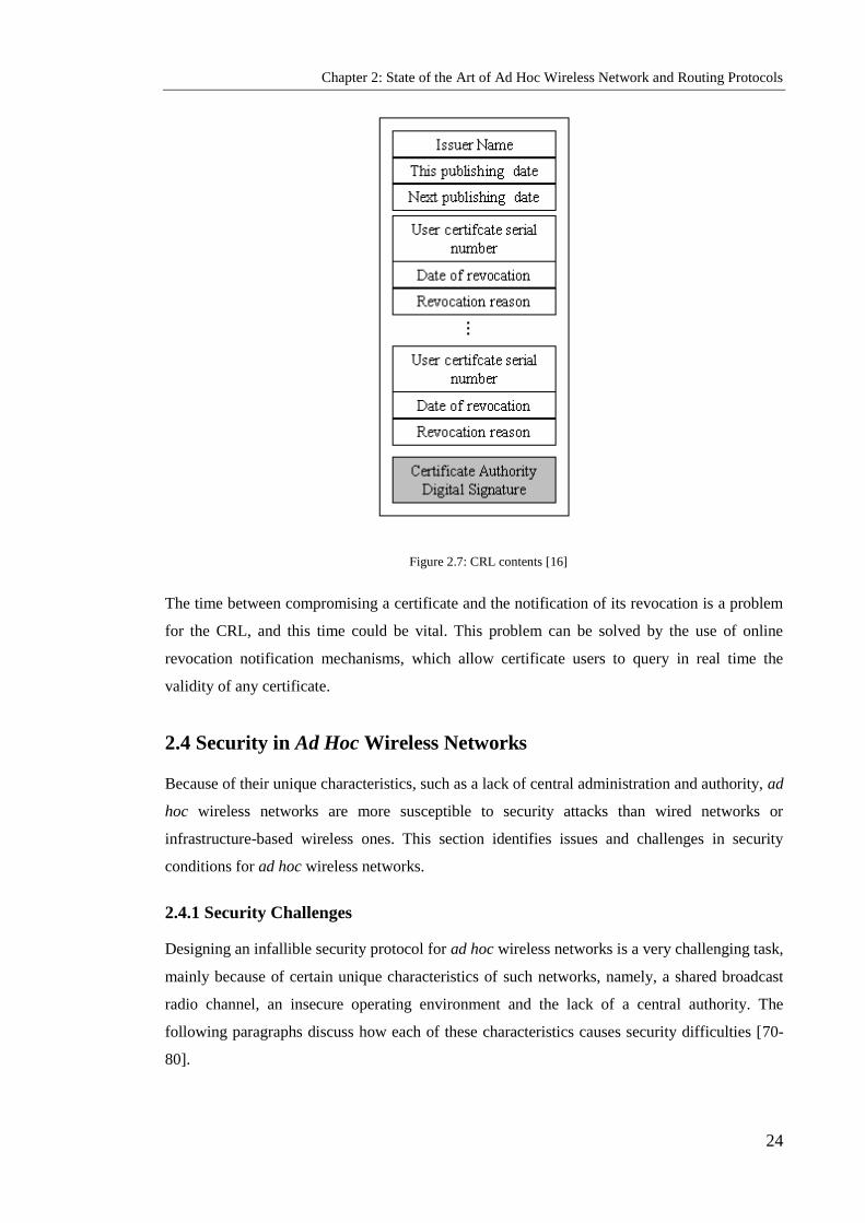
Chapter 2: State of the Art of Ad Hoc Wireless Network and Routing Protocols
24
Figure 2.7: CRL contents [16]
The time between compromising a certificate and the notification of its revocation is a problem
for the CRL, and this time could be vital. This problem can be solved by the use of online
revocation notification mechanisms, which allow certificate users to query in real time the
validity of any certificate.
2.4 Security in Ad Hoc Wireless Networks
Because of their unique characteristics, such as a lack of central administration and authority, ad
hoc wireless networks are more susceptible to security attacks than wired networks or
infrastructure-based wireless ones. This section identifies issues and challenges in security
conditions for ad hoc wireless networks.
2.4.1 Security Challenges
Designing an infallible security protocol for ad hoc wireless networks is a very challenging task,
mainly because of certain unique characteristics of such networks, namely, a shared broadcast
radio channel, an insecure operating environment and the lack of a central authority. The
following paragraphs discuss how each of these characteristics causes security difficulties [70-
80].

Chapter 2: State of the Art of Ad Hoc Wireless Network and Routing Protocols
25
Shared radio channel
In traditional wired networks, a transmission line is provided to each end user, whereas in ad
hoc wireless networks, a radio channel is used for communication and is public in nature, being
shared by all nodes in the network. Data transmitted by any one node is received by all nodes
within its direct communication range, allowing a malicious node to obtain easy access to it.
Insecure operational environment
The environment in which ad hoc wireless networks operate may not always be secure. One
important example is on a battlefield, where its nodes can move freely in and out of enemy
territory and are thus highly susceptible to security attacks.
Lack of central authority
In wired networks and infrastructure-based wireless networks, a central authority can manage,
control and monitor all traffic on the network through certain central points, such as routers and
access points, making it possible to implement security mechanisms at such points. These
cannot be applied in ad hoc wireless networks, by contrast, since they have no such central
points.
Lack of association
Ad hoc wireless networks are dynamic in nature, any node being free to move in or out of the
network at any time. If there is no suitable authentication mechanism being used for uniting
nodes within a network, then an interloper would be able to join it easily and carry out attacks.
Limited resource availability
Resources such as bandwidth, battery power and computational power are limited in ad hoc
wireless networks, making it difficult to implement complex cryptography-based security
mechanisms.
Physical vulnerability
The nodes in ad hoc wireless networks are usually compact and hand-held, so they can become
damaged and are also susceptible to theft and loss.
2.4.2 Key Management
Ad hoc wireless networks face certain particular challenges in key management owing to their
reduced infrastructure. There are three types of infrastructure [17] which are absent from ad hoc
wireless networks: a routing infrastructure in the shape of dedicated routers and stable links

Chapter 2: State of the Art of Ad Hoc Wireless Network and Routing Protocols
26
which ensure communication with all nodes; a server infrastructure, such as a domain name
service, directory services and TTP services; and the organisational and administrative support
of certifying authorities.
The concept of keys is central to cryptography, as noted in section 2.2.3. Two important related
functions are the generation and distribution of keys, the responsibility of a party trusted by all
entities. The majority of the mechanisms used to provide security services require the use of
some type of cryptographic keys that need to be shared between the communicating parties. In
this subsection we discuss the commonly used key management services.
2.4.2.1 Trusted Third Party
A TTP is an entity trusted by all users in the network; it is often responsible for providing key
management services. A TTP may come in many different forms, such as a key distribution
centre (KDC), a key translation centre (KTC) or a certification authority. The KDC and KTC
are symmetric key management systems, while the CA is a public key management system.
KDCs and KTCs are used to simplify key management; as an alternative to each node having to
share a secret key with every other node, they need to share only one with the TTP. This reduces
the number of keys that need to be managed from n(n-1)/2 to n, where n is the total number of
users.
On the other hand, CAs are used for public key cryptography in the Public Key Infrastructure
(PKI), which means that any two nodes wishing to connect must exchange their public keys in
an authenticated manner, requiring the initial distribution of n(n-1) public keys. However, by
having a TTP to issue certificates, only the public key of the TTP needs to be distributed to each
of the nodes. The CA is a component that is responsible for issuing and revoking certificates,
and they can be categorised by the nature of their participation.
Figure 2.8 illustrates the different categories of TTP: in-line, on-line and off-line. An in-line
TTP can be involved actively between the connection path of the two nodes, while an on-line
TTP participates actively but only for management functions; the actual connection between the
nodes is direct. An off-line TTP‘s connection with the nodes is created before setting up a
connection link. Through the actual protocol run, the off-line TTP is not active; indeed, it does
not even need to be connected to the network.

Chapter 2: State of the Art of Ad Hoc Wireless Network and Routing Protocols
27
Figure 2.8: In-line, on-line and off-line TTPs
2.4.2.2 Cluster-based Approach to Ad Hoc Wireless Networks
One interesting approach is to divide the network into a number of clusters, each with a
different membership. Each cluster selects a cluster head (CH) node with a role different from
that of its other members [18]. The CH establishes a backbone and acts as key manager, while
the transmission encryption key (TEK) is updated periodically. Before operation, updating the
TEK entails a re-clustering and the selection of a new CH. One of the advantages of rotating the
CH role is that doing so avoids exhaustion of the nodes acting as CHs, and accounts for
mobility. Nodes that were once neighbours when the cluster was shaped may have moved out of

Chapter 2: State of the Art of Ad Hoc Wireless Network and Routing Protocols
28
the neighbourhood. This approach has a number of susceptibilities that may cause the system to
fail, however; for example, when the CH is malicious it will make part of the cluster fail, which
is a serious disadvantage of this approach.
2.5 Ad Hoc Wireless Network Layers
The Open Systems Interconnection reference model proposed by the International Organisation
for Standardisation consists of seven layers [3], namely, the physical, data link, network,
transport, session, presentation and application layers (Figure 2.9). Each layer is assigned a
unique set of functions and responsibilities.
The first and lowest layer is the physical layer, which may need to adapt to rapid changes in the
characteristics and mobility of wireless links. It is responsible for the transmission of the bit
stream over the physical medium and the time duration of each bit. It handles the mechanical
and electrical specifications of the network hardware. The mechanical specifications refer to the
physical specifications of the devices, such as connectors and cables used for interconnection.
The second layer is the data link layer, whose main objective is to coordinate the access of
multiple nodes in a shared (wireless) medium, to ensure error-free transmission of data across a
physical link. It receives data from a higher layer, divides it into several frames/packets, then
transmits the frames. The data link layer is also responsible for reducing collisions arising as a
result of simultaneous transmissions by multiple nodes, maximizing throughput, allowing fair
access and the use of directional antennas.

Chapter 2: State of the Art of Ad Hoc Wireless Network and Routing Protocols
29
Figure 2.9: Communication between nodes A and D [3]
The third layer is the network layer, which is responsible for routing data packets from the
source node to the destination node to which the data packets belong. Thus, the network layer
has to acquire and distribute information used to set up routes between sources and destinations
in a way that maintains efficiency when links change frequently. The network layer is also
responsible for node addressing; a packet may have to cross several networks in order to reach
its destination.
Next is the transport layer, providing a network of higher layers which is independently
interfaced to the lower layers. The main functions of the transport layer protocol include
handling delay and packet loss statistics that are very different from wired networks,
segmentation and reassembly of packets, assigning and maintaining end-to-end connections,
reliable end-to-end delivery of data packets and end-to-end error recovery. A key responsibility
of this layer is congestion control in the local network.
Finally, the application layer enables users to access the network. Its main roles are to handle
regular disconnection and reconnection with peer applications and to support data transmission
and services, such as electronic mail, remote file access and file transfer between users.
Application
Presentation
Session
Transport
Network
Data Link
Physical
Application
Presentation
Session
Transport
Network
Data Link
Physical
Network
Data Link
Physical
Network
Data Link
Physical
Device A Device D
Device C Device B

Chapter 2: State of the Art of Ad Hoc Wireless Network and Routing Protocols
30
2. 6 Summary
Ad hoc Wireless Networks have various defining characteristics that differentiate them from
other wired and wireless networks such as infrastructureless, dynamic topology, constrained
resources, limited device and physical security, and short range connectivity. These
characteristics present nontrivial challenges for Ad hoc Wireless Networks such as security,
scalability, and QoS.
The unique characteristics of Ad hoc Wireless Networks, namely a shared broadcast radio
channel, an insecure operational environment, lack of central authority, lack of association,
limited resource availability and physical vulnerability, make such networks highly vulnerable
to security attacks compared to wired networks or infrastructure-based wireless networks
This chapter has investigated the major issues and applications of Mobile Ad hoc Network of
Networks were described. Moreover, this chapter discusses all the general information of ad hoc
networks and tackles security challenges, security requirements and security attacks. The
applications of ad hoc wireless networks include military applications, collaborative and
distributed computing and emergency operations. Each of the challenges, security requirements
and security attacks are discussed in detail.

Chapter 3: Critical Review of Routing Protocols and Secure Routing in Ad hoc Wireless Network
31
Chapter 3
Critical Review of Routing Protocols and Secure Routing in
Ad hoc Wireless Networks
Objectives: to present
Challenges in routing
Requirements of routing protocols for ad hoc wireless networks
Classifications of current routing protocols
Secure routing in ad hoc wireless networks
3.1 Introduction
The routing protocol has two main functions: the first is to find a feasible data packet path from
a source node to a destination node; the second is to identify and exchange the routing
information as a routing table, required for establishing the routing path, discovering path
breaks, re-establishing or repairing broken paths and reducing bandwidth utilization. The nodes
in an ad hoc network function as routers which discover and maintain routes to other nodes in
the network. This absence of dedicated routers makes the provision of security a challenging
task in ad hoc wireless networks, where the task of ensuring secure communication is also made
difficult by factors including the mobility of nodes, limited processing power and limited
availability of resources such as battery power and bandwidth.
3.2 Challenges in Routing
The main challenges facing the routing protocol designed for ad hoc wireless networks are as
follows [1, 2]:
Mobility of nodes
The mobility associated with nodes, which is considered a primary characteristic of ad hoc
networks, raises many issues such as packet collision, regular path breaks, stale routing
information and difficulty in resource reservation. Their resolution requires a good routing
protocol which is able to interpret them efficiently.

Chapter 3: Critical Review of Routing Protocols and Secure Routing in Ad hoc Wireless Network
32
Other resource constraints
Constraints on resources such as battery power and buffer storage can limit the capability of the
routing protocol.
Error-prone channel state
The bit error rate is very high in a wireless channel compared with its wired counterparts and
the design of the routing protocol should take this into account. Taking into consideration the
state of the wireless link, the signal to noise ratio and path loss for routing could improve the
efficiency of the routing protocol.
Location-dependent contention
As the number of nodes existing in a given geographical zone varies, so does the load on the
wireless channel. Thus, if the number of nodes increases, this raises the contention for the
channel. A good routing protocol can avoid such difficulties by means of inbuilt mechanisms
for distributing the load uniformly across the network.
Bandwidth constraint
Since bandwidth for transmission is limited in ad hoc wireless networks, the bandwidth
available per wireless link is based on the traffic each link carry and the number of nodes. Thus,
a good routing protocol should keep bandwidth usage to a minimum.
3.3 Requirements of Routing Protocols for Ad Hoc Wireless Networks
Routing protocols designed for traditional wired networks cannot be used in ad hoc wireless
networks because of the unique characteristics of these networks; they require specialised
routing protocols that address the challenges listed above. Such a protocol should therefore have
the following features [2, 10]:
Distributed operation
The protocol should be fully distributed, as centralized routing involves high control in order to
have improved reliability. Since all nodes are mobile, it is unacceptable to have a centralized
routing protocol. Each node should make routing decisions using information gathered from
other mutual nodes.

Chapter 3: Critical Review of Routing Protocols and Secure Routing in Ad hoc Wireless Network
33
Dynamic
As an alternative to assuming that traffic is uniformly distributed within the network and
maintaining routing between all nodes at all times, the algorithm must be adaptive to regular
topology changes caused by the mobility of the nodes.
Loop-free
A good routing protocol should be loop-free in order to avoid wasting bandwidth and so
improve overall performance.
Unidirectional link support
Unidirectional links can and do occur in wireless networks because the radio environment and
utilization of these links improve the routing protocol performance. However, in situations
where a pair of unidirectional links (in opposite directions) form the only bi-directional link
between two areas of an ad hoc network, the ability to make good use of them is extremely
valuable.
Security
Without some form of network-layer or link-layer security, an ad hoc routing protocol is
susceptible to many forms of attack, such as impersonation. It may be relatively simple to spy
on network traffic, replay transmissions and redirect routing messages within a wireless network
without proper security requirements. Hence there is a need for preventive security measures.
Encryption and authentication may help to solve security issues and to prevent such attacks.
Power conservation
Nodes in ad hoc wireless networks depend on the very limited supply of power via batteries, so
the routing protocol should optimise the use of this scarce resource.
Quality of service support
The routing protocol should be implemented to provide a certain level of quality of service and
should also be in real time to support current traffic.
3.4 Classifications of Current Routing Protocols
Routing protocols proposed for mobile ad hoc wireless networks can be classified by the
routing information update mechanism into three categories: proactive, on-demand and hybrid.
An alternative classification is based on temporal information for routing, which, given the
lifetime of the wireless links and of the paths selected, assumes significance. Routing protocols

Chapter 3: Critical Review of Routing Protocols and Secure Routing in Ad hoc Wireless Network
34
can also be classified according to whether the address topology is flat or hierarchical, or on the
basis of the utilization of specific resources. These categories are not mutually exclusive, since
some protocols could be classified into more than one group. The research in this report is
related to routing protocols based on the routing information update mechanism. Thus, only this
category will be discussed and the following subsections will examine in turn the three major
groups listed above: proactive (periodic), reactive (on-demand) and hybrid [2, 24, 25, and 26].
3.4.1 Proactive Routing Protocols
Proactive routing protocols are also called table-driven, since every node maintains one or more
tables to store the network topology and routing information. This information is updated
frequently by periodically exchanging the routing information, which is generally flooded
throughout the whole network. Proactive routing protocols have many differences between
them, dependent on the method of discovering and updating the routing information and on the
types of information maintained in the routing tables.
These protocols are extensions of the traditional wired network. Examples of such protocols are
the Destination Sequence Distance Vector (DSDV) routing protocol [27] and the Wireless
Routing Protocol (WRP) [28, 29]. Other routing protocols, based on link state algorithms, have
also been proposed; examples are the Optimised Link State Routing [30], Fisheye State Routing
[31, 32], Source Tree Adaptive Routing [33] and Global State Routing protocols [34].
Three examples of protocols that belong to the table-driven category are detailed below. These
are DSDV, WRP and Cluster-head Gateway Switch Routing (CGSR).
3.4.1.1 Destination-Sequenced Distance-Vector
The DSDV algorithm [27], an enhanced version of the Distributed Bellman-Ford algorithm [35,
36], uses incremented sequence numbering for each destination in order to guarantee faster
convergence and resolves the loop and count-to-infinity problems. One of the first protocols to
have been proposed as being appropriate for ad hoc wireless networks, it uses the distance
vector‘s shortest path routing algorithm to select the path to a destination. As it is a table-driven
routing protocol, the routing table is maintained at each node that contains the shortest distance
and at the first node on the shortest path to every other node on the network. The routing tables
are exchanged between neighbours at regular intervals in order to keep the routing information
and network topology up to date. In addition, the node forwards the table when it observes a
significant change in the local topology since the last full table updating. Therefore, any
required route to all destinations is continuously available at every node at all times.

Chapter 3: Critical Review of Routing Protocols and Secure Routing in Ad hoc Wireless Network
35
This exchange in routing tables between nodes in the network introduces a large amount of
control overhead to the network; thus, two methods are used to update the routing tables in
order to reduce the control overhead broadcast through the network. The first type of update is a
‗full dump‘ update packet, which is used when significant changes are observed in the local
topology or when more data packets need to be carried in an incremental update. Hence, this
type of update carries all the current routing information. Alternatively, when there are no major
changes in the local topology, then the incremental update packet is utilised, comprising only
the information altered since the latest full dump occurred. Incremental update messages are
propagated more frequently than full dumps.
A new sequence number is used by the destination node to initiate a table update. It is always
greater than the previous one for a particular destination node. Based on the sequence number of
the table update, the node may either forward or reject the table. The node has two choices for
updating its routing tables if it receives an updated table: either update its routing tables based
on the newly received information, or keep it for some time in order to select the best path from
the multiple update table received from different neighbouring nodes.
Route maintenance of a broken link in DSDV is handled by the end node of the broken link and
initiates a table update message. This message assigns the broken link‘s weight to infinity and a
sequence number greater than the stored sequence number for that destination. Each node that
receives an updated table on an infinite weighting entry quickly disseminates it to its neighbours
in order to propagate the broken link information to all nodes in a network. In this way, when a
single link break occurs, it leads to the propagation of table update information to the whole
network.
DSDV algorithms have a number of advantages and disadvantages. First, the routes are
available of times to all destinations in the network. Maintaining an up-to-date view of the
network topology at all the nodes is propagated throughout the network. On the other hand, the
periodic update messages still introduce large amounts of overhead to the network (the interval
time is in seconds). The number of route to discover packets (overhead) is the complexity of
the number of nodes in the entire network equivalent to the order O(N2), where N is the number
of nodes. The scalability of the network is affected by this complexity. As a result, the protocol
is effective for forming small ad hoc wireless networks, but it is not scalable for large ones,
because a large portion of the network bandwidth is utilised in the updating procedures, making
topologies highly dynamic. A large amount of time is spent generating and updating the routing
tables under the DSDV protocol. Another disadvantage is the instability of the network for a
period of time before the update packets reach all the nodes in the network, causing a high
mobility rate among them.
Chapter 3: Critical Review of Routing Protocols and Secure Routing in Ad hoc Wireless Network
36
3.4.1.2 Wireless Routing Protocol
WRP [28] uses the predecessor information (readily available routing information) to ensure
fast convergence and freedom from the count-to-infinity problem. Under WRP, every node has
a readily available route to every destination node in the network in order to maintain an up-to-
date view of the entire network and routing information among all nodes. Each node maintains
four routing tables: a distance table (DT), a routing table (RT), a link-cost table (LCT) and a
message retransmission list (MRL). The DT contains the network view of the neighbours of a
node, where each element comprises the distance and the penultimate node reported by a
neighbour for a specific destination. It shows the shortest distance, the penultimate node and the
next node to reach destinations, as well as a flag indicating the status of the route. The LCT
gives the number of hops to reach a destination, by relaying messages through each link and
recording the number of update intervals between two successive periodic passes, while the last
successful update was received from that link. Each element of the MRL is used for an update
message that is to be retransmitted and a counter is maintained for each element. When sent, the
update message contains the sequence number of the update message, a retransmission counter
and a list of updates. If the retransmission counter reaches zero after entries in the update
message for which no acknowledgment has been received, a retransmission of the update
message will be deleted.
Update messages are used between neighbouring nodes in the network to bring their routing
tables up to date. These contain a list of updates: the destination, the distance to the destination,
the predecessor of the destination and a list of responses indicating which mobiles should
acknowledge the update. Each node in the network can modify the elements of its DT regarding
the distance to the corresponding nodes, which can be checked for new possible paths through
other nodes when receiving the update message.
The main advantage of WRP lies in the fact, explained above, that it is free from temporary
routing loop and count-to-infinity problems, which it is able to avoid when performing
consistency checks on the predecessor information reported by all the neighbours of a node in
the network. This terminates looping situations and involves fewer table updates if a link failure
event occurs. Nevertheless, the complexity of maintaining multiple routing tables demands a
larger memory and greater processing power from nodes in the ad hoc wireless network. The
increased amount of control overhead involved in updating table entries at high mobility in
WRP is substantial; hence it is not suitable for higher dynamics or for very large ad hoc wireless
networks.

Chapter 3: Critical Review of Routing Protocols and Secure Routing in Ad hoc Wireless Network
37
3.4.1.3 Cluster-head Gateway Switch Routing
CGSR [37] uses a hierarchical network topology, unlike other table-driven routing approaches,
which are based on flat topologies. CGSR organises nodes into clusters and in each cluster a
special node named a cluster head is selected dynamically by employing an algorithm called
Least Cluster Change [38], which deals with two cases where there is a change of CH. The first
is when two cluster heads come into one cluster. When it is using lowest-id or highest-
connectivity, this will lead to a situation where one node has to relinquish its CH status. The
second case obtains when one of the nodes moves free and out of range of all CHs. All member
nodes of a cluster within communication range can be reached by the cluster head in a single
hop. The CH keeps all necessary information on other nodes, such as the track of the nodes in
its own cluster and of the other cluster-heads.
CGSR assumes the CH and all communications passing through it. Communication between
two CHs takes place through common member nodes or gateway nodes which are in the
communication range of both and are members of both clusters. Thus, the transmission of data
packets takes place through cluster heads and gateways in a path such as:
CHGatewayCHGatewayetc.
In CGSR, every member node maintains two tables: the first is a routing table listing the
destination CH for every node in the network and the second is a distance vector routing table of
next-hop nodes for reaching each destination cluster. The CH node transmits the cluster member
table periodically and every node updates its own table when it receives this table update. When
a node has a data packet to be routed, it identifies the nearest cluster head to the destination
from the cluster member table and the routing table. It can then find from its routing table the
next hop node to reach the selected CH and transmit the packet to that node.
An advantage is that the routing table is reduced in size by grouping nodes into clusters and
keeping one entry for each destination cluster. CGSR also allows better bandwidth utilization
and it is easy to implement priority scheduling schemes with symbol scheduling and gateway
code scheduling, because CGSR is based on clustering nodes and routing transmissions through
the cluster heads.
The main disadvantages of this protocol are an increase in the path length and instability in the
network at high mobility when the rate of change of cluster heads is high, which degrades the
performance of the protocol. In addition, complexity and overhead are caused by the selection
of the CHs, causing difficulty in continually maintaining the cluster structure in a mobile
environment. Another matter of concern is the power consumption at the CH nodes, because the

Chapter 3: Critical Review of Routing Protocols and Secure Routing in Ad hoc Wireless Network
38
battery-draining rate at these nodes is faster than at normal nodes. This may lead to frequent
changes in the CH and single point failures at the CHs and gateways, which may cause multiple
path breaks. All these will reduce the scalability of the network, which is particularly
undesirable.
3.4.2 Reactive Routing Protocols
Several protocols of the reactive routing type have been proposed, the most typical being
Dynamic Source Routing (DSR) [38, 39], Ad hoc On-demand Distance Vector (AODV) [40],
the Temporarily Ordered Routing Algorithm [41, 42], Associativity-Based Routing (ABR) [43,
44] and Signal Stability-based Adaptive (SSA) routing [45].
These protocols, also called on-demand routing protocols, are proposed for mobile ad hoc
wireless networks only. The primary characteristic of such networks is their dynamic topology;
hence, because they follow the topology changes, regular updates of global topology
information are required at every node. Sometimes the received routing information updates
may expire before being needed; this further complicates matters and the routing of obsolete
information wastes bandwidth. Johnson proposed the concept of reactive or on-demand routing
to reduce unnecessary updates and thus the amount of bandwidth consumed.
By establishing the necessary routes when required (on demand), using a route discovery
process and source, on-demand routing protocols, unlike proactive ones, do not maintain the
network topology information and route to each destination of the network. Generally, when a
route is needed by a source S, a route request packet propagates it into the network to construct
a route to the required destination, D. When D receives the RREQ, it then sends a route reply
(RREP) packet back to S. When the route request has travelled through bi-directional links,
RREP is sent using link reversal, or by piggybacking the route in an RREP packet through
flooding. In on-demand routing protocols, we have the main functions of the routing algorithm,
which are route discovery and route maintenance.
Reactive protocols can be categorised according to the route information carried in data packets
as either source routing (full path) or hop-by-hop (point-to-point) routing protocols [46]. In
source routing protocols such as DSR [39] and ABR [43, 44], all data packets carry the
complete route address from source to destination nodes. Therefore, the data packet in the
header of this packet is forwarded towards the destination along the path mentioned previously.
An advantage of using this type of protocol is that there is no need to maintain neighbour
connectivity at intermediate nodes, nor therefore to maintain routing information for each active
route for forwarding the packet towards the destination at intermediate nodes.

Chapter 3: Critical Review of Routing Protocols and Secure Routing in Ad hoc Wireless Network
39
In point-to-point routing approaches, as with the AODV protocol [40], the data packet needs to
specify only the destination and next hop addresses. The intermediate nodes are used for
forwarding the packet towards the destination along the path to maintain routing tables. Using
routing tables at every node in the network provides an advantage to hop-by-hop routing, in that
dynamically updating the network topology ensures that nodes receive recent topology
information and can forward data packets over current best routes.
3.4.2.1 Ad hoc On-demand Distance Vector
The AODV routing protocol [40] is a reactive routing algorithm of the hop-by-hop type. In
order to ensure that routes are kept up to date and that the most recent routing information is
used, AODV uses sequence numbers. It differs from other generic on-demand systems in that it
finds a route to the intended destination by using the sequence numbers of both source and
destination, thus streaming the RREQ packet across the network. The RREQ packet contains the
IP address of the source node and the destination node, the broadcast ID, the current sequence
number of the source and the time to live (TTL) field.
The validity of a route in AODV at an intermediate node is determined by the corresponding
destination sequence number, which is greater than or equal to that contained in the RREQ. If
the node wants to send, RREP places the recent sequence number of the destination as its
distance in hops to the destination into the RREP, then an RREP is returned to the source along
the path followed by the RREQ. Once the source node receives the RREP packet, it will start
transmitting data packets to the destination. If the route discovery timer expires and the source
node has not received an RREP, it rebroadcasts the RREQ. This process is repeated up to some
predetermined maximum number of times, after which if no route is discovered (no RREP is
received) the session is aborted.
In case a link break occurs while the route is active and any neighbour of the upstream node
uses that link, the node generates and propagates a route error (RERR) packet to the source node
to inform it about the link break. The RERR packet contains all IP addresses of unreachable
nodes, because the link break and their sequence numbers are incremented by one. The node
then broadcasts the packet and deletes these routes from its route table. After receiving the
RERR, if the source node still needs the route, it reinitiates the path-finding process.
The main advantage of the AODV protocol is the familiarity of the on-demand approach to
establishing routes. On the other hand, a serious drawback is that multiple RREP packets in
response to a single RREQ packet can add to the already heavy control overhead occurring as a

Chapter 3: Critical Review of Routing Protocols and Secure Routing in Ad hoc Wireless Network
40
result of flooding the RREQ packet across the network. This is very costly in contention and
collision, which results in serious redundancy.
If an RREQ packet is sent to all neighbours during route discovery, each neighbour in turn
forwards it to its own neighbours, without taking into account whether they are about to move
out of range. In time, this could lead to failure in sending data along a discovered route, as a link
break could occur through a neighbour moving out of range of the previous node on the path.
3.4.2.2 Heading-directional Angle Routing Protocol
The core of the proposed schemes is the Heading-direction Angle Routing Protocol (HARP)
[49], so called because it utilizes directional information on nodes in the network. Such
information can be obtained from the node‘s own instruments and sensors, such as a compass,
which delivers the heading-direction angle (HDA) of the mobile device relative to magnetic
north. This protocol is used to reduce routing overhead and to increase the lifetime of links
between nodes. It has been assumed that every node can exchange information frequently with
its neighbours. Under HARP, every node classifies its neighbouring nodes into eight different
zones according to their heading direction. In theory, the nodes are categorised within at least
one of the eight zone ranges, regardless of their location. This protocol is based on an on-
demand routing technique. The RREQ packet is transmitted from a node to one of the
neighbouring nodes that has an angular heading direction similar or near to the HDA of
neighbouring nodes, where D is a value used for increasing the search around ND.
When a source node S sends a request for a route to destination node D, it will look into its
cache for D and if it is found, node S will start broadcasting the data packets to node D. If D is
not found, a time Td will be initiated by source node S, where Td is the time required to find the
destination. Then, node S starts searching in its cache for a neighbour that has a reference or
near reference angle matching with or close to the HDA of S.
This protocol reduces the overheads and minimises bandwidth usage, since not all neighbouring
nodes need to reply to a RREQ. Its main advantage is that it increases the lifetime of links
between nodes. A disadvantage is that when the source node receives an error message, it will
resend the request packet; the limited amount of sending avoids the formation of a loop without
taking into account whether it knows the accurate path. Another drawback of HARP is the
classification of different zones that are not suitable for the network if it is of high or low
density. This protocol does not seem useful as an axis mapping technique, despite its use.

Chapter 3: Critical Review of Routing Protocols and Secure Routing in Ad hoc Wireless Network
41
3.4.2.3 Dynamic Source Routing Protocol
The DSR protocol [38, 39], proposed at Carnegie Mellon University, uses source routing as a
substitute for hop-by-hop packet routing and is designed particularly for use in multi-hop ad hoc
wireless networks. In DSR, the elimination of periodic table-update messages means that a very
large bandwidth is consumed by the control packets needed to establish routes.
The major difference between DSR and AODV is that DSR reply messages include the full path
between the source and destination nodes. In addition, the RREQ packet includes addresses of
every node visited before broadcasting it across the network. Every node which receives an
RREQ retransmits the packet to its neighbours if either it has not already forwarded it or the
node is not the destination node. Upon receiving a route request packet, the destination node
sends a route reply back to the source. The RREP carries the route crossed by the RREQ.
There are three advantages to using source routing and sequence numbers:
It denies loop formation.
It obviates the need for up-to-date routing information in the intermediate nodes when
packets are forwarded.
It avoids retransmitting the same route packet or multiple transmissions by an
intermediate node.
These techniques have been incorporated into the basic DSR protocol to improve its
performance and the utilisation of the route cache information at intermediate nodes in reply to
the source when they receive a route request packet. In this case, the intermediate nodes could
have a route to a similar destination. Another optimization is to remove the route acquisition
latency by piggybacking data on route request packets.
In addition to these the major advantage of this protocol is that it eliminates the need to burden
the network with periodic update messages, by establishing routes only on demand. On the
other hand, broken links cannot be mended locally through the route maintenance mechanism.
Instead, a link break causes an RERR packet to be sent to the source node to invoke a new route
discovery phase. Nodes that receive a route error message may also receive stale route cache
information, which uses the broken link. Another disadvantage is that DSR does not work well
in large networks because each packet carries the full path to the destination in its header. The
performance of DSR also degrades rapidly with increasing mobility, but it is good in static and
low mobility environments. In spite of finding the route on demand, a considerable routing
overhead is involved, owing to the source-routing mechanism employed in DSR, through
flooding RREQ; this is directly proportional to the path length. The DSR establishment
Chapter 3: Critical Review of Routing Protocols and Secure Routing in Ad hoc Wireless Network
42
mechanism can cause a long delay as a result of a packet needing to be transmitted through a
new link. In on-demand techniques, exploiting one of the positive aspects of mobility reduces
the effectiveness of that mobility, producing a more adaptive mechanism but one which requires
longer lived links, in order to reduce the overhead caused by propagating the route request
packets in the network.
3.4.2.4 Associatively-Based Routing Protocol
ABR [43, 44] is a beacon-based, on-demand routing protocol invented by Toh [44] and
developed at Cambridge University. It is a distributed routing protocol designed for mobile ad
hoc networks and was selected for the stability of the wireless link. The link is organized and is
stable or unstable depending on its temporal stability. This is determined by counting the
periodic beacons that a node receives from its neighbours. Each node in the ABR protocol
produces periodic ―hello‖ messages to represent its existence to its neighbours. It maintains the
count of its neighbours‘ beacons and this is used to update the associativity table of each node.
Since the nodes use the temporal stability and the associativity table, they are able to categorise
each link with a neighbour as stable or unstable, depending on the beacon count corresponding
to the neighbour node concerned. The link corresponding to an unstable neighbour is termed an
unstable link, while a link to a stable neighbour is called a stable link. ABR is a source routing
protocol that has no need for periodic route updates.
When the route to the destination is not available in the cache, the source node initiates the route
discovery by propagating route request packets throughout the network. All the intermediate
nodes forward these packets only once when they receive them. Every intermediate node adds
its address and its beacon count to the packet. The destination waits for a period, TRouteSelectTime,
from when it receives the route request packet before selecting the route that has the maximum
proportion of stable links. It will select the shortest route if it has received multiple routes that
have the same overall degree of stability.
If a link break occurs at an intermediate node, it is detected through the beacons, and then the
node closest to the source which detects the break initiates a local route repair process by locally
broadcasting a route repair packet with limited TTL. If this node fails to repair the broken link,
then the next node in the path to the source (the uplink node) reinitiates the local query
broadcast. This route repair process continues along the line of intermediate nodes toward the
source node until the node in the middle of the broken path fails to repair the dead link, in which
case the source is informed, triggering a new route establishment phase.
Chapter 3: Critical Review of Routing Protocols and Secure Routing in Ad hoc Wireless Network
43
The main advantages of ABR is that more stable routes are preferred over shorter routes, which
results in fewer path breaks and in turn reduces the extent of propagation because of the
reconfiguration of paths in the network. However, the chosen path may sometimes be longer
than the shortest path between the source and destination, owing to the preference given to
stable paths; this is one of the disadvantages of this protocol. Another is that local query
broadcasts may result in long delays during route repair.
3.4.2.5 Signal Stability-Based Adaptive Routing Protocol
The SSA routing protocol, proposed by Dube et al. [45], bases the selection of routes on the
signal strength between two nodes and their location stability, which identifies those paths
which have existed for longer than others. The SSA protocol, like ABR, uses beacon messages
between nodes where the signal strength of the beacon is measured to determine link stability.
According to the received signal strength, a link is classified as stable or unstable. This
technique requires SSA to use an extended radio interface to measure the signal strength from
beacons. SSA consists of two cooperative protocols: the Forwarding Protocol (FP) and the
Dynamic Routing Protocol (DRP). FP performs the routing to forward a packet on its way to the
destination, while DRP maintains the routing table and the Signal Stability Table (SST) by
interacting with its processes on other nodes. The SST contains the beacon count and is based
on the signal strength of its neighbour‘s beacons. This table is used to forward the route request
from the nodes in the path to the destination, over strong links, to find the most stable end-to-
end path. If a node has received strong signals from the last few beacons, then it considers the
link to the sending node as strong and stable.
If the destination is not available in the routing table, FP initiates a route request packet to detect
a route. The crucial task in route detecting is that route request packets are forwarded to the next
node, but only if they are received over strong links and have not been previously processed.
The packets are silently dropped before being processed when they are received over a weak
link. If the source node fails to find the stable links needed to construct any path to a destination
in order to forward a route request, then the FP propagates the route request across the network
without considering the stability of links as a forwarding criterion. In this case, the destination
chooses the link which is received on the first route packet request and triggers the sending of a
route reply packet back to the source. The DRP hops along the links, updating their routing
tables accordingly; thus the route request packets reach the destination via the links of strongest
signal stability.
The major advantage of the SSA protocol is that it forwards packet between nodes along stable
routes, depending on the signal strength, but a concomitant disadvantage is that if stable links

Chapter 3: Critical Review of Routing Protocols and Secure Routing in Ad hoc Wireless Network
44
are not available to forward a route request between two nodes, then the sender node propagates
the route request across the network without considering the stability of links as a forwarding
criterion. Each node receiving route request packets over weak links should drop it before it is
processed. In this case, if there is no stable link but there are some other links with different
weakness ranks, the node cannot take one of these links, even though it is possible that one of
them may be available and strong after a short period of time. Hence, the node still drops the
RREQ, without selecting the strongest link among the weak ones. Another disadvantage of SSA
is that when a node detects a link break that is not repaired, it sends an error packet to the source
node, notifying it of which link has failed. If the error packet reaches the source node, it sends
an erase packet to notify all nodes in the path of the broken link and triggers a new route request
process to choose a new path to the destination. This causes an increase in multiple RREQs,
flooding the network and reducing available bandwidth.
3.4.3 Hybrid Routing Protocols
Hybrid routing protocols are designed to be both reactive and proactive in order to classify and
offer different routing solutions. They increase the network‘s scalability, which allows nearby
nodes to define a local zone, while determining routes to distant nodes using a reactive
approach. In order to reduce route discovery overheads, neighbouring nodes work together by
proactively maintaining routes to nearby nodes.
Most proposed hybrid protocols are based on zones, which mean that the network is partitioned.
Each given node partitions a zone of the network into two distinct regions. The routing zone for
a particular node can be defined in terms of distance from that node or as lying inside a
particular geographical region. This routing uses a proactive (table-driven) approach; a reactive
routing approach uses nodes located in the area beyond the routing zone. The most typical
hybrid types are the Zone Routing Protocol (ZRP) [47] and the Core Extraction Distributed Ad
hoc Routing (CEDAR) algorithm [48]. The latter selects a minimum set of nodes as a core to
perform quality of service route computations.
3.4.3.1 Zone Routing Protocol
ZRP [47] is a hybrid routing protocol that combines the best features of on-demand and
proactive routing protocols. That is, ZRP splits a network into limited zones according to the
nodes of a local neighbourhood. Each node has an intra-zone and an inter-zone. The protocol
uses a proactive routing scheme within the former, a limited zone in the r-hop neighbourhood of
the node, while for nodes in the inter-zone beyond this it uses a reactive routing scheme. The
intra-zone is referred to as a routing zone. Thus, each node can be within multiple overlapping

Chapter 3: Critical Review of Routing Protocols and Secure Routing in Ad hoc Wireless Network
45
zones in the network and each zone may be of a different size. The size of a zone is given by its
radius, whose length is the number of hops to the inner boundary of the zone. For each node, the
peripheral nodes are those whose distance from it is equal to the zone radius. ZRP is similar to a
cluster system in dividing the network area into a number of zones, with the difference that in
ZRP, every node performs as a cluster head and a member of other clusters.
Each node uses proactive routing protocols to maintain routing information on nodes within its
routing zone. When any of those nodes moves outside the routing zone and inter-zone
connections are required, reactive routing is adopted. In the routing zone, the proactive
IntrAzone Routing Protocol (IARP) is responsible for maintaining routes to destinations. IARP
can be any proactive routing protocol, based on the implementation. The reactive Interzone
Routing Protocol, which is used to find routes to destination nodes outside the routing zone,
adopts a reactive routing approach, using RREQ and RREP packets in order to discover a route.
The Broadcast Resolution Protocol is the type of broadcasting used when a node requires a
route to a destination and the intended destination is not in the routing table of IARP; ZRP
considers that the destination node must be outside its routing zone. Thus, the broadcasting of
RREQs will continue from one node‘s peripheral nodes to other peripheral nodes until the
destination node within its zone is reached.
Since ZRP is a hybrid routing protocol that exhibits better performance owing to its use in both
reactive and proactive schemes, it has the advantage of limiting the periodic propagation
(proactive overhead) of the nodes within the routing zone. It also restricts the reactive route
detection (search overhead) to selected peripheral nodes. However, it is potentially inefficient if
the RREQ packet is to propagate across the entire network and because the use of hierarchical
routing in finding the path to a destination could be suboptimal. As the size of the routing zone
is increased, greater memory is needed and each node will need to have a higher level of
topological information. Table 3-1 shows the performance comparison between the protocols

Chapter 3: Critical Review of Routing Protocols and Secure Routing in Ad hoc Wireless Network
46
Table 3.1: Performance comparison between protocols
Routing
technique
Source
route
Neighbour
detection
Loop freedom
maintenance
Multiple
paths
Communication
Overhead
AODV
Reactive/
Flooding
No HELLO message Sequence number No High
DSR
Reactive/
Flooding
Yes No Source route Yes High
DSDV
Proactive/
Flooding
No HELLO message Sequence number Yes High
FSR
Link state
update
No
Periodical link
state
updates
Limited scope
(multi-level scope No
reduces the routing
update overhead in
large networks
WRP Proactive No HELLO message
sequence number
and checks of
predecessor
information
Yes High
CGSR Proactive No
broadcasts
cluster member
table periodically
Limited scope of
transmission to a
cluster
No
the selection of the
cluster-heads causes
overhead
ABR
Reactive /
based on the
wireless link
stability
No
periodic beacons
between the
neighbour nodes
sequence number No Low
SSR
Reactive /
based on the
signal strength
No beacon messages
between nodes sequence number No Low
ZRP Hybrid No Hello message in
the Intrazone sequence number Yes Low in outer zone
3.5 Secure Routing in Ad Hoc Wireless Networks
The nodes in ad hoc wireless networks act both as regular terminals (source or destination) and
as routers for other nodes in the network, unlike fixed wired networks such as the Internet,
where dedicated routers are controlled by a service provider. This absence of dedicated routers
makes the provision of security a challenging task in ad hoc wireless networks, where the task
of ensuring secure communication is also made difficult by factors including the mobility of

Chapter 3: Critical Review of Routing Protocols and Secure Routing in Ad hoc Wireless Network
47
nodes, limited processing power and limited availability of resources such as battery power and
bandwidth.
The requirements of a secure routing protocol for ad hoc wireless networks are as follows [2]:
Detection of malicious nodes: If there are malicious nodes in a network, then a secure
routing protocol should be able to detect them and avoid selecting them in the routing
process.
Guarantee of correct route discovery: The protocol should be able to find a route when
one exists between the source and the destination; it should also ensure that it is correct.
Confidentiality of network topology: Malicious nodes will be able to view disclosure and
information regarding network topology that may lead to an attack on these networks.
The confidentiality of the network topology is an important requirement in order to
prevent a potential attacker from studying the traffic pattern of the network. Thus, the
attacker will not be able to discover the active nodes in ad hoc wireless networks and all
attempts to mount e.g. Denied of Service (DoS) attacks against such bottleneck nodes will
fail.
Stability against attacks: The routing process in ad hoc wireless networks should not be
disrupted permanently by passive or active attackers. The routing protocol must be self-
sustainable; thus it must be able to revert to its normal operating state within a finite
amount of time after a passive or active attack. The protocol must ensure Byzantine
robustness; that is, the protocol should work correctly even if some of the nodes which
have previously participated in the routing process turn out later to be malicious or are
intentionally damaged.
The following sections discuss some of the security-aware routing protocols proposed for ad
hoc wireless networks.
3.5.1 Proactive RSA
The proactive RSA [19] protocol was not designed in particular for ad hoc wireless networks;
however, many other protocols used in this type of network are based upon it. The essential
characteristic of the proactive RSA is that it uses distributed shared keys. It is more difficult for
an adversary to find these, because they are updated frequently. The device is a mechanism used
to share a key and update it frequently without revealing secret values; these are the main goals
of this protocol, which functions by communicating through an authenticated bulletin board.
The avoidance of jamming and the capability of nodes to restart (re-initialise) a compromised
node are the main advantages of this protocol. On the other hand, it supplies only probabilistic

Chapter 3: Critical Review of Routing Protocols and Secure Routing in Ad hoc Wireless Network
48
stages of security and requires a trusted dealer to authenticate the initial group to create the
authenticated bulletin board.
3.5.2 Security-aware Ad Hoc Routing Protocol
The Security-aware Ad hoc Routing (SAR) protocol [20] uses security as one of the key metrics
to find paths, incorporating a structure for enforcing and measuring features of the security
metric. This structure uses different levels of security for different applications that use the SAR
protocol for routing. The communications between end nodes in ad hoc wireless networks are
made through (possibly multiple) intermediate nodes, depending on the fact that the two end
nodes trust the intermediate nodes. One of the tasks of SAR is to define the level of trust as a
metric for routing. This means that every path for packets is associated with a security level,
which is determined by a numerical calculation. A certain level of security is also associated
with every intermediate node. When an intermediate node receives a packet it compares its level
of security with that defined for the packet, and if the packet‘s security level is less than that of
the node, then this node is considered to be a secure node and is permitted to view the packet. If
it is greater, the packet is simply discarded.
The SAR mechanism could easily be incorporated into traditional routing protocols for ad hoc
networks. SAR permits the application to select the level of security it requires; however, the
protocol requires different keys for different levels of security. The main disadvantage of this
mechanism is that it tends to increase the number of keys required when the number of security
levels used increases.
3.5.3 Authenticated Routing Protocol
The Authenticated Routing Ad hoc Network (ARAN) protocol [21] provides secure routing for
ad hoc wireless networks by means of cryptographic certificates that successfully defeat all
identified attacks in the network layer. It takes care of authentication, message integrity and
non-repudiation, but expects a small amount of prior security coordination among nodes. In
general, the main requirements it attempts to fulfil are first preventing things such as the
spoofing of routing signals, the fabrication of routing packets, the shaping by adversaries of
routing loops and the exposure by routing packets of the network topology; and secondly
ensuring that such routing packets are not altered during transmission and that the shortest
routing path is utilised.
The major drawback of the protocol is that it needs a trusted certification server to issue the
initial certificates. It offers security at two levels. The first, which is not fully secure, is an end-
to-end authentication that is effective and requires low CPU power; however, it does not

Chapter 3: Critical Review of Routing Protocols and Secure Routing in Ad hoc Wireless Network
49
guarantee the shortest path usage. The second is stronger in security and guarantees to provide
the shortest path, but requires more CPU power and resources. The ARAN protocol prevents
compromised nodes from disrupting the network by providing route maintenance mechanisms
and key revocation schemes.
3.5.4 Secure AODV
The Ad hoc On-demand Distance Vector routing protocol [22] provides security by securing the
routing information. It uses schemes such as digital signatures, depending on source and end-to-
end authentication. The protocol protects non-mutable data (not required or changed in the
routing process) by use of public-key schemes. It secures the mutable data (necessary for the
routing process), which in this case is the hop count information that uses hash chains. AODV
uses a key management scheme and proposes a distributed CA to issue and validate the digital
signature. The source performs the following three tasks:
It uses a public-key encryption scheme
It signs the data
It uses a hash function to encrypt the hop information.
On the path, every router will use a hash function to encrypt and update the hop information in
order to secure it. When the destination receives the message, it uses the same hashing chain to
verify the path and uses its keys to obtain the rest of the data and authenticate it. This scheme
consumes less CPU power from the intermediate nodes, since they do not require access to the
encrypted data. However, it still requires some authority structure to provide and manage the
nodes with valid certificates.
3.5.5 Secure Efficient Ad hoc Distance Vector
The Secure Efficient Ad hoc Distance vector (SEAD) routing protocol [23] is a secure routing
protocol for ad hoc wireless networks depending on the DSDV. This protocol protects against
DoS attacks, reduces the overhead and speeds up the routing process, since it uses efficient one-
way hash functions. It also assumes a limited network diameter in order to reduce the amount of
information needed in the routing table and any exchange of information between nodes. As in
secure AODV, it uses the incremental hash function of the route information to identify a
correct path to the destination node. It also needs a similar security association between the
source and destination nodes.
SEAD avoids routing loops except the loop that includes more than one attacker. This protocol
could be implemented easily with minor changes to the existing distance vector routing

Chapter 3: Critical Review of Routing Protocols and Secure Routing in Ad hoc Wireless Network
50
protocols. It is robust against multiple uncoordinated attacks. Nonetheless, SEAD is unable to
defeat attacks where the attacker uses the same sequence number and metric which has been
used by the latest update message and sends a new routing update.

Chapter 3: Critical Review of Routing Protocols and Secure Routing in Ad hoc Wireless Network
51
3.6 Summary
In this chapter, the major issues of routing in Ad hoc wireless Networks were described.
Moreover, this chapter discusses all the general information of routing and secure routing .The
routing is one of the important cores in mobile ad-hoc networks. Every routing protocol has its
strengths and drawbacks and aims at a specific application. In addition, the strengths of a
protocol could be drawbacks in another protocol. Current routing protocols provide routing
solutions up to a certain level for certain scenarios. However, they are lacking the ability to
handle other scenarios with related points (such as nodes mobility with long-lived routes to the
destination). If these protocols could be extended further, or new routing protocols are designed
by taking into account other routing related factors, it may come out with a standard routing
solution for mobile ad-hoc networks.

Chapter 4: Enhanced Heading Direction Routing Protocol and Modelling
52
Chapter 4
Enhanced Heading Direction Routing Protocols and
Modelling
Objectives: to present
Present research methodology
Present simulation environment
Present key idea of heading direction
Present modelling of ad hoc networks
4.1 Introduction
Several routing protocols have been proposed for ad hoc networks as a solution to major
problems such as mobility effects in multi-hop communication and overhead. These lead to
significant control overhead and interference to ongoing traffic, which are often unacceptable.
Flooding techniques may result in excessive redundancy, contention, broken links and collision.
This outcome is notorious as the ―broadcast storm problem‖ [86].
In order to reduce the overhead and flooding effect, Kumar and Xue [87] propose a scheme to
reduce the overhead involved in the discovery of a route to the end node. This scheme utilises
forwarding packets to certain nodes, which fall within a determined direction. These
intermediate nodes are selected according to their location and that of the final destination.
However, the scheme does not take into account the lifetime of the links between neighbouring
nodes, which would be necessary to establish long-lived routes and guarantee selection of the
optimal path.
The work reported in this thesis falls into the category of on-demand routing protocols. As
mentioned in chapter 3, a serious drawback of AODV and HARP are the generation of multiple
RREP packets in response to a single RREQ packet, leading to heavy control overhead added to
that caused by the flooding of the RREQ packet across the network. This overhead is very
costly and results in serious redundancy, contention, increased broken links and collisions.
Chapter 4: Enhanced Heading Direction Routing Protocol and Modelling
53
Thus, one of the aims of the approach proposed here is to reduce the rate of broken links and
improve the guarantee of optimal path selection in on-demand routing protocols.
The core of the proposed scheme is the Heading-direction Angle, so called because it utilizes
directional information on the nodes in the network. Heading direction information can be
obtained from a node‘s own instruments and sensors, such as a compass, which delivers the
HDA of the mobile device relative to magnetic north. This protocol is used to reduce routing
overhead.
In the proposed approach, which is an enhanced version of HARP based on demand techniques,
the effect of the mobility of nodes is reduced by exploiting one of the positive aspects of
mobility, which is the heading direction. At the same time, the lifetime of the link is elongated,
in order to produce a more adaptive mechanism with mobility and in order to reduce the
overhead caused by flooding the network with route request packets.
4.2 Research Methodology
The research methodology adopted to attain the research goal comprises the following main
steps and activities: (1) identification of problems (via an intensive literature review), (2)
concept presentation, (3) designing the approaches, (4) concept development, (5) validation and
evaluation, (6) reflection and feedback, and (7) documentation/ reporting of findings and
identification of directions for future research and development. Note that in practice the
process is inherently iterative.
The research study was initiated with a two-stage literature review consisting of state-of-the-art
and in-depth reviews. The state-of-the-art review was conducted for the recognition of up-to-
date developments in mobile ad hoc networks. Since the aim of this research is to design a new
routing approach and a new secure routing protocol, the literature review focused on the
following areas: routing protocols and mechanisms for ad hoc networks, the security of ad hoc
networks, security requirements, and the security mechanism and application spectrum of ad
hoc networks.
The purpose of the second (in-depth) stage of the literature review was to identify specific
research problems and their potential solutions, which may have been researched previously but
not sufficiently extensively. The focus of this research has been on the route lifetime, the
reduction of broken links and strengthening the guarantee of selecting the optimal path, in
addition to ensuring a secure routing protocol and a secure environment. Note that this step was
conducted continuously and in parallel with steps 3 to 6 above, throughout this study. This was
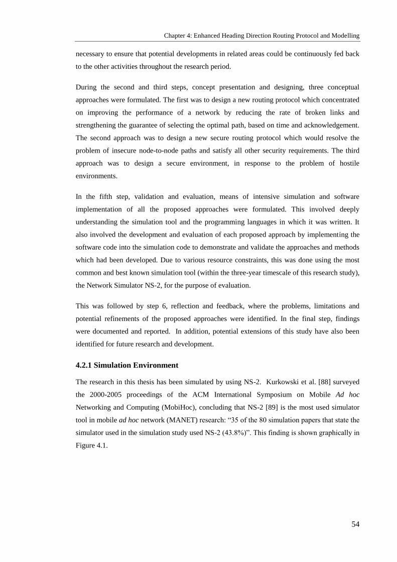
Chapter 4: Enhanced Heading Direction Routing Protocol and Modelling
54
necessary to ensure that potential developments in related areas could be continuously fed back
to the other activities throughout the research period.
During the second and third steps, concept presentation and designing, three conceptual
approaches were formulated. The first was to design a new routing protocol which concentrated
on improving the performance of a network by reducing the rate of broken links and
strengthening the guarantee of selecting the optimal path, based on time and acknowledgement.
The second approach was to design a new secure routing protocol which would resolve the
problem of insecure node-to-node paths and satisfy all other security requirements. The third
approach was to design a secure environment, in response to the problem of hostile
environments.
In the fifth step, validation and evaluation, means of intensive simulation and software
implementation of all the proposed approaches were formulated. This involved deeply
understanding the simulation tool and the programming languages in which it was written. It
also involved the development and evaluation of each proposed approach by implementing the
software code into the simulation code to demonstrate and validate the approaches and methods
which had been developed. Due to various resource constraints, this was done using the most
common and best known simulation tool (within the three-year timescale of this research study),
the Network Simulator NS-2, for the purpose of evaluation.
This was followed by step 6, reflection and feedback, where the problems, limitations and
potential refinements of the proposed approaches were identified. In the final step, findings
were documented and reported. In addition, potential extensions of this study have also been
identified for future research and development.
4.2.1 Simulation Environment
The research in this thesis has been simulated by using NS-2. Kurkowski et al. [88] surveyed
the 2000-2005 proceedings of the ACM International Symposium on Mobile Ad hoc
Networking and Computing (MobiHoc), concluding that NS-2 [89] is the most used simulator
tool in mobile ad hoc network (MANET) research: ―35 of the 80 simulation papers that state the
simulator used in the simulation study used NS-2 (43.8%)‖. This finding is shown graphically in
Figure 4.1.

Chapter 4: Enhanced Heading Direction Routing Protocol and Modelling
55
Figure 4.1: Simulator usage, from the Mobile Hoc survey [88]
In an attempt to generate results that would be representative of some potential real-world
scenarios which the algorithms in this thesis might encounter, simulations were run with
parameters close to the available realistic values. Without loss of generality the protocol
evaluations are based on the simulation of 50 wireless nodes for some scenarios and on a
number of nodes varying from 10 to 70 for other scenarios. These nodes form an ad hoc
network moving about over a flat area of 1000 m x 1000 m for 500 seconds of simulated time.
The square site models situations in which nodes can move freely around each other and where
there is a small amount of path and spatial diversity available for the routing protocol to
discover and use. The dimension of 1000 m, which is four times the transmission range, was
chosen in order for there to be a reasonable number of nodes between the source and destination
nodes, because a higher number of intermediate nodes results in quicker route breaks, whereas a
smaller number would not give an indication of the realistic routing protocol. This protocol,
most of the time, needs some intermediate nodes to establish the connection between two
communicating nodes. Another reason for selecting a square with 1000 m sides was to keep the
average number of neighbouring nodes equal to or higher than the required number of
neighbours in EHARP. The number of neighbour nodes is based on transmission range R and
the simulation area:
)5(2
n
lw
RnodesNeighbour
where w and l are the width and the length of the network area. According to the parameters
used for simulating the work, there are approximately 9 neighbour nodes. The physical radio
characteristics of each mobile node‘s network interface, such as the antenna type, transmit
power and receiver sensitivity, were chosen to approximate the best known commercially

Chapter 4: Enhanced Heading Direction Routing Protocol and Modelling
56
available wireless LAN radio products such as Lucent WaveLAN [90] radio. Some well known
wireless LANs are listed in Table4.1 [91].
Table 4-1: Wireless LAN Products
Company Product Advertised Speed Advertised Distance
AT&T WaveLAN 2 Mbps 800 feet
Digital RoamAbout 2 Mbps 800 feet
NCR WaveLAN 2 Mbps 800 feet
Solectek AirLAN 2 Mbps 800 feet
A Tcl script file for ad hoc wireless simulations provided with NS-2 distribution was modified
to fit the simulation environment of the project. In this file, it was necessary to define the type
for each of the network components constituting a mobile node, such as the link layer, the
interface queue, the MAC layer and the wireless channel on which nodes transmit and receive
signals. Additionally, in the Tcl script file, it is necessary to define other parameters including
the type of antenna, the radio-propagation model and the type of ad hoc routing protocol used
by mobile nodes.
The size of trace files generated by running the Tcl script file is huge (of the order of tens of
MB). These files were analysed to obtain the performance metrics. In order to extract certain
lines and discard the rest from the generated trace file for analysis, the AWK utility language
was used. AWK is a programming language included with the UNIX operating system that is
designed for processing text-based data, either in files or data streams. For example, to extract
only the information related to route request packets, it was decided to write a programming
code using AWK, because writing programming code to do these tasks in languages such as C,
C++,java or Pascal is time consuming and inconvenient, while such jobs are often easier with
AWK. The AWK utility interprets a special-purpose programming language that makes it easy
to handle simple data-reformatting jobs and allows us to extract pieces of data for processing, to
sort data and to perform simple network communications [92].

Chapter 4: Enhanced Heading Direction Routing Protocol and Modelling
57
4.3 The Key Idea of Heading Direction
This section explores the using of heading information to improve the performance of routing
protocols for ad hoc wireless networks. As a demonstration, this section shows how a route
discovery protocol based on mobility information can be improved. Consider two mobile nodes
1n and 2n that are within the transmission range R of each other, where ),( 11 nn yx , 1nv and
),( 22 nn yx , 2nv are the coordinates and velocities of 1n and 2n respectively. In addition, 1n and
2n move in direction 1n and 2n from the north respectively (Figure 4.2).
Figure 4.2: Communication between two nodes in an ad hoc wireless network [93]
As can be seen in Figure 4.2, the total time that the two mobile nodes remain connected depends
on the difference between 1n and 2n as denoted by [8]:
22
2222 )()()(
qp
lqpdRqpqdplT
(6)
where
,sinsin 2211 nnnn vvp
,21 nn xxl
,coscos 2211 nnnn vvq

Chapter 4: Enhanced Heading Direction Routing Protocol and Modelling
58
The distance between the two nodes changes with time. Note that when n1 and n2 move in a
similar direction the link between them lasts longer. Figure 4.3 depicts the relation between T
and the difference between 1n and 2n , with 1021 nn vv , R = 50, 1011 nn yx and
2022 nn yx .
It is clear from Figure 4.3 that the time to path break is increased when the difference between
the direction angles of the two nodes is decreased. Hence, the link will last longer when the next
node in the link is selected as having a similar direction to the upstream node. If the velocities of
the two nodes are equal and 012 nn , assuming that no other channel conditions affect the
channel link, the time to path breaks increases to infinity [84].
Figure 4.3: Lifetime of link vs. difference between heading angles of end nodes [84]
In order to apply the idea explained above for selecting the next node in the route during the
route discovery process, extra data is needed, in the form of the node heading direction. This
could be provided by utilising a compass with Magneto Resistive (MR) technology [93], which
delivers the heading direction angle of the mobile device relative to magnetic north. The
expected lifetime of a link has been examined by Turgut et al. [71] and Samar et al. [94], who
.21 nn yyd
0
20
40
60
80
100
120
140
0.03
0.13
0.31
0.73
2.83
3.22
3.35
3.61
Life
tim
e o
f th
e li
nk
(tim
e)
(Rad)

Chapter 4: Enhanced Heading Direction Routing Protocol and Modelling
59
derive the relation between the lifetime of a link and the difference between the motion angles
of two communicating nodes.
4.4 Principle of the Heading Direction Mechanism
The core idea of the proposed scheme is termed Enhanced Heading-direction Angle Routing
Protocol (EHARP), as it makes use of direction information on the nodes in the network. The
aim of using the heading direction is to reduce routing overhead and to increase the lifetime of
links between communicating nodes. It has been assumed that each mobile node in the network
knows its own heading direction by using a digital compass with MR technology. Most
navigation systems today use some type of compass to determine heading direction. Electronic
compasses based on MR sensors can determine electrically a change in direction of 0.1° and can
easily be integrated into systems via a simple communication interface, which makes it ready
for use in applications that need such information [93].
The general behaviour of ad hoc networks is to deliver the data packet to the destination
through intermediate nodes. Therefore, it is assumed that all hosts wishing to communicate with
other hosts in the network are willing to participate fully in the protocols of the network: each
node is willing to receive and forward packets for others nodes in the network. Moreover, each
node periodically exchanges heading direction information with its neighbours and stores the
information received in its cache memory.
4.4.1 Categorization of Nodes
Under EHARP, each mobile node in the network classifies its neighbouring nodes according to
their heading directions into four different zone-direction groups: Z1, Z2, Z3 and Z4, as can be
seen in Figure 4.4. The heading directions between 0° and 90° are categorised as zone-direction
1 (Z1); those between 90° and 180° as zone-direction 2 (Z2) and so on. For example, consider
that a mobile node (MN) has a neighbour node moving in a heading direction 60° and sending
its heading direction information periodically to its own neighbouring nodes. The MN, when it
receives the heading direction information from this neighbour, will classify it as in Z1.
Theoretically, the neighbouring nodes of a mobile node are categorised within at least one of the
four zone ranges, regardless of their actual positions relative to the mobile node itself.

Chapter 4: Enhanced Heading Direction Routing Protocol and Modelling
60
Figure 4.4: Neighbours categorised within four basic zone ranges
4.4.2 Downstream Node Selection
The proposed approach (EHARP) is based on the on-demand routing technique; this means that
establishing routes are based on route requests and route replies. In other words, when a source
node S wishes to send data packets to a destination D, in order to find a route to D, it will send a
RREQ packet. Almost all on-demand routing schemes require that the route request be
forwarded towards the destination through intermediate nodes. This means that each node will
forward the RREQ to the next downstream node. (Nodes towards the destination are called
downstream nodes, whilst those lying in the direction of the source are called upstream nodes).
In the proposed EHARP approach, when an intermediate node wants to forward a packet to a
downstream node, it selects this from its neighbouring nodes, which are classified according to
their heading direction and stability of link. The selected node has an angular heading direction
similar or near to the heading direction angle of the selecting node and the highest stability of
link. For example, consider a node with a heading direction angle, #Node . The selected
downstream node has the nearest heading direction angle and highest value of SL to
)( # node , where is an angle around #Node to expand the search. By doing so, the lifetime
of the link between the two nodes will last longer and the stability of link will be maximised.
These parameters are reflected in the routing functionality, in that this approach reduces the
effects of mobility and reduces the packet drop rate. In addition, selecting an appropriate
downstream node will result in lower computational overhead and minimise the packet drop

Chapter 4: Enhanced Heading Direction Routing Protocol and Modelling
61
rate, because not all neighbouring nodes will need to react to a route request. If the node does
not find a neighbour that fulfils the heading angle condition or if the stability of link of all such
neighbours is poor, the search will be expanded by applying the axis-mapping technique, as
shown in Figure 4.5.
To widen the search, the angular value represented by is increased, so a large range of heading
directions are taken into consideration when a route request message is being propagated or a
route reply message is being sent along an already established route.
Figure 4.5: Axis mapping technique; is added and subtracted through 45°[94]
4.4.3 Route Records List
When a source node wishes to send a packet to a destination node it will initiate the Route
Records List (RRL) if it does not find the destination node in its cache memory (a neighbour
table). The source node then adds a record to the RRL containing information about itself. Each
RRL record has the following fields:
A node IP address, which is the IP address of the node that is involved in the route.
A node-heading angle, which is the heading direction angle of the node itself.
A zone-direction number, which is the number of the zone in which the heading direction
angle of the node falls and which has a range of values from 1 to 4.
SL counter, giving the status of links between these nodes.
The RRL will be attached in the header of the route request packet, which is propagated to the
appromate node(s) depending on the scheme used in routing. Each node visited by the RREQ
during its transmission will adds a new record to the RRL containing information about the
visited node itself.

Chapter 4: Enhanced Heading Direction Routing Protocol and Modelling
62
4.5 Modelling Ad Hoc Wireless Networks
This section presents the definition of the general system model for the routing algorithm and
describes the network model, mobility model and traffic model. It also elaborates on the format
of messages, routing tables and the general route establishment mechanism used by the
proposed algorithm.
4.5.1 Definition of the System Model
The proposed EHARP routing algorithm is intended for use by any mobile device and is able to
work in a peer-to-peer mode (ad hoc wireless network). Complete functions and tasks expected
from this protocol have to be achieved via a distributed algorithm, which exploits the mobility
and stability of links between users to offer adaptation to dynamic topology changes and
frequent link breaks, low control traffic overhead, elongation of link lifetime and reduction of
the packet drop rate. To ensure loop freedom, some other existing routing protocols utilise
destination sequence numbers, in addition to which EHARP uses the RRL to provide an
additional guarantee of freedom from the counting-to-infinity problem. Each record in the RRL
contains information about a node involved in the route between the source and the destination
node. This algorithm can be adopted by other routing protocols to improve their performance.
4.5.2 Assumptions
Some assumptions have to be made in order to accomplish the tasks of the proposed routing
algorithm. These are:
1. Each mobile node works in group and is willing to exchange all information of heading
direction and stability link with its neighbours in a timely manner. The information
received from a neighbour node will be stored in one of the four zone-directions in the
cache memory regardless of the actual position of that neighbour.
2. Each node is able to obtain the necessary routing information by direct communication
with a resource which provides this information whenever it is required. Alternatively,
the mobile node is equipped with a device such as a digital compass, which delivers the
heading direction angle of the mobile device hosting it.
3. The function of ad hoc wireless networks is to transmit data packets through relay nodes
between the sender and the receiver. Therefore, it must be assumed that each node in the
network is willing to forward other nodes‘ packets as well as its own.
4. The nodes move at roughly similar speeds to people in the street.

Chapter 4: Enhanced Heading Direction Routing Protocol and Modelling
63
4.5.3 Models
This section presents three models: the network, mobility and traffic models.
4.5.3.1 Network Model
A multi-hop ad hoc wireless network consists of a set of nodes, N. The area of the network, A,
that nodes move in depends on the application and the purpose of the network. The distribution
of nodes in A also depends on the scenario that the network is running. It can be predetermined
for some applications such as in a classroom, conference or meeting room, whilst for other
applications, the nodes are randomly distributed (such as in search-and-rescue or free user
movement). Therefore, the density of nodes in the area (N/A) varies from application to
application and from one subsection of A to another.
Assuming that the transmission range of each node is equal to R and every node has an omni
directional antenna, the transmission/communication between any two nodes n1 and n2, (where
Nnn 21, ) is successful if it satisfies the two conditions:
If the distance between these two nodes is 21nnd , the condition Rd nn
21 should be
satisfied;
If the interference range of the receiving node n2 is Rint, any node ( Nm ) within Rint of
the receiving node n2, int2Rdmn is not transmitting. In general, the transmission range is
the same as the interference range.
In the case of IEEE 802.11 MAC protocols [44], the sending node n1 is also required to be free
of interference, as it needs to receive the link layer acknowledgement from the receiving node
n2. Therefore, in IEEE 802.11MAC protocols, a node m falling in the interference range of the
nodes n1 or n2 must not be transmitting.
The hidden and exposed terminal problems are generally the concern of the MAC protocols.
They do not affect wired networks and occur only in wireless ones. The hidden terminal
problem arises from a simultaneous transmission by nodes that are hidden from each other; in
other words, they are not within the direct transmission range of the sender but are within the
transmission range of the receiver. In this situation, a collision of packets at the receiving node
occurs when nodes transmit packets simultaneously without knowing about transmission by
each other. As can be seen in Figure 4.6, both node N1 and node N2 try to transmit to node G1 at
the same time, because neither is aware of the transmission of the other, being hidden from each
other. This means that the two node packets will collide at node G1.

Chapter 4: Enhanced Heading Direction Routing Protocol and Modelling
64
Figure 4.6: Hidden and exposed problems in ad hoc wireless networks
The exposed terminal problem occurs when one node is blocked from transmitting by another
nearby transmitting node. In Figure 4.6, N3 cannot transmit to G2 because the transmission from
N1 to G1 is already in progress and the transmission of N3 would interfere with this ongoing
transmission.
The performance of ad hoc wireless networks is reduced by the occurrence of the hidden and
exposed terminal problems, especially when the traffic load is high. Therefore, the design and
development of a MAC protocol should consider the potential for these problems and take
appropriate measures.
4.5.3.2 Mobility Model
The EHARP algorithm is proposed for ad hoc wireless networks with a minimum number of
mobile nodes, which varies with the scheme used in routing. The proposed algorithm requires a
different minimum number of nodes in the network to guarantee establishment of the route from
the source node to the destination node. In EHARP, each node sends an RREQ packet to only
one neighbour. Hence, a low density of nodes is acceptable but, of course, the higher the
number of available neighbours to select from, the more appropriate the selected neighbour will
be increases the performance of EHARP.
Since the EHARP algorithm depends on the direction movement of mobile nodes and it is an
on-demand algorithm, it can handle low and moderate mobility rates. Clearly, in ad hoc wireless
networks, mobility models are application dependent. Moreover, the various mobility patterns
affect the performance of different network protocols in different ways. For example, the
performance of the routing protocol under the scenario of the group mobility model (such as in
a highway or military group) differs from that of a random mobility or random walk mobility
model.

Chapter 4: Enhanced Heading Direction Routing Protocol and Modelling
65
The random mobility model is the one most commonly used by researchers. In the Random
Waypoint mobility model [74], nodes are randomly placed within the simulation field at the
start time. Each node selects a destination randomly and independently from other nodes,
moving to it at a constant speed. When it reaches the destination, it stays there for a given pause
time before starting to move to another random destination. In the EHARP algorithm, selecting
the next appropriate node when establishing the route depends on the heading direction
information. Hence, the mobility model is not strongly affected by the performance of these
algorithms, because of its adaptiveness to the direction of movement, where a node selects the
next node from those that are moving in a similar direction and highest value of SL to the
current node. For example, in the group mobility scenario, all nodes move in the same
determined direction, so there is an easier and wider choice of the next node. Under a random
scenario, there are still neighbour nodes to select from, with near similar directions and highest
value of SL to that of the current node.
4.5.3.3 Traffic Model
The physical model is directly related to the physical layer characteristics. The transmission
from node n1 to n2 is successful if the signal-to-noise ratio (SNR) at node n2, SNRn1n
2, is not less
than a minimum threshold: SNRn1n
2 ≥ SNRthresh. Since the work in this thesis is related to the
network layer, the physical model is beyond the scope of this discussion. As it is assumed that
each mobile node has an omnidirectional antenna model, the propagation model combines a free
space propagation model with a two-ray ground reflection multipath model. In the free space,
the power of a signal attenuates as 2/1 d , where d is the distance between the transmitter and
the receiver. For this work, it is assumed that the propagation range of mobile nodes is equal.
4.5.4 General System Model
This section describes the messages used by the EHARP algorithm, the routing tables used to
maintain the routing information and the general route establishment mechanism.
4.5.4.1 Message Formats
In the proposed algorithm, as in other routing algorithms of mobile ad hoc wireless networks, a
number of messages are used to perform the task of running the algorithm. These messages are
used to establish routes and for sending data packets from a source node to a destination node.
The required format for each message, the fields that each message consists of and the
contribution of each message to the achievement of routing in mobile ad hoc wireless networks
are described.

Chapter 4: Enhanced Heading Direction Routing Protocol and Modelling
66
4.5.4.1.1 Route Records List Format
In the RRL, each record contains the node‘s IP address, its heading direction angle and its zone-
direction number. Each node in the network which contributes to setting up the route or which is
involved in forwarding the data packet to the destination has a record in the list, which is
constructed during the stage of finding the path to the destination. An additional task of this list
is to share with the destination the sequence numbers, preventing the counting-to-infinity
problem. Other details of the RRL are explained in subsection 4.4.3. The field names of the
RRL used in the proposed approach are shown in Table 4.2.
Table 4.2: Route records list format
Field Name Description
lr_nodeIP Node IP address
lr_nodedir Node heading angle
lr_zonerange Zone-direction number (1-4)
lr_nodeSL Stability of link
4.5.4.1.2 Route Request Message Format
If the destination node is not a neighbour to the source node, the route request message is
initiated and prepared by the source node with the necessary information before being
transmitted onto the network. The fields most commonly required in the RREQ message are the
source and destination IP addresses, the RRL and the packet type (to differentiate between route
request, route reply, route error, acknowledgment and hello messages). The general field names
used in the RREQ message is shown in Table 4.3.

Chapter 4: Enhanced Heading Direction Routing Protocol and Modelling
67
Table 4.3: Route Request Message Format
Field Name Description
rq_type Packet Type
rq_bcast_id Broadcast ID
rq_dst Destination IP Address
rq_dst_seqno Destination Sequence Number
rq_src Source IP Address
rq_src_seqno Source Sequence Number
rq_timestamp When RREQ sent; to compute route discovery latency
rq_rt_list Route Record List
4.5.4.1.3 Route Reply Message Format
The route reply message is initiated and prepared with necessary information by the destination
node or by an intermediate node, which has a fresh enough route to the destination node. The
RREP is then unicast back to the source node that generated the RREQ. In our proposed
scheme, the RREP message consists of identical fields. In general, the main fields required in
the RREP message are the source and destination IP addresses the RRL and the packet type.
Here, it is important to notice that the Destination IP Address field refers to the node that
generates the RREQ message, while the Source IP Address field denotes the node that generates
the RREP message. The general field names used in the RREP message are shown in Table 4.4.

Chapter 4: Enhanced Heading Direction Routing Protocol and Modelling
68
Table 4.4: Route Reply Message Format
Field Name Description
rp_type Packet Type
rp_dst Destination IP Address
rp_dst_seqno Destination Sequence Number
rp_src Source IP Address
rp_lifetime Lifetime
rp_timestamp When corresponding RREQ sent; used to compute route
discovery latency
rp_rt_list Route record list
4.5.4.1.4 Route Error Message Format
The route error message is initiated and prepared by an intermediate node when a broken link to
the next node is discovered. In addition, an RERR is initiated if the time required to find the
destination expires without the destination being reached (further explanation is given below).
The route error message is filled with necessary information before it is unicast over the
network towards the source node that generated the RREQ. In our proposed scheme, an RERR
message consists of the same fields: it should contain all the IP addresses of the nodes that have
not been reached because the error has occurred, accompanied by their sequence numbers. The
general fields used in the RERR message are shown in Table 4.5.

Chapter 4: Enhanced Heading Direction Routing Protocol and Modelling
69
Table 4.5: Route Error Message Format
Field Name Description
re_type Packet type
re_DestCount Destination count
re_unreachable_dst[] List of unreachable destination IP addresses
re_unreachable_dst_seqno[] Unreachable destination sequence numbers
4.5.4.1.5 Hello Message Format
Selecting the next hop according to the heading direction of the next node requires that the node
should be aware of the heading directions of its neighbour nodes. Each node in the network is
required to broadcast local hello messages with one hop distance every hello interval time. The
determined value of the interval time should be a compromise between the local control
overhead and the information update frequency. Before determining that the neighbour no
longer exists as a neighbour because there are no more hello messages being received from it, a
number of lost messages should be allowed.
In general, the main fields required in the RREP message are the node IP address, its sequence
number and the node heading direction angle. The general fields used in the hello message are
shown in Table 4.6.

Chapter 4: Enhanced Heading Direction Routing Protocol and Modelling
70
Table 4.6: Hello Message Format
Field Name Description
hl_type Packet Type
hl_IP_Node Node IP Address
hl_Node_seqno Node Sequence Number
hl_hop_count Hop Count
hl_nodedir Node direction
hl_nodesl Node stability of link
4.5.4.2 Table Formats
This section describes the format of the routing tables used by the proposed algorithm, which
contain the routing information used to establish routes between nodes and information about
neighbours.
4.5.4.2.1 Routing Table Format
Since EHARP is an on-demand routing protocol, it should be noted that algorithm needs a
routing table to keep information about all known routes. The routing table also needs special
algorithm management such as adding new routes, deleting expired or broken routes and
searching in the table for a route to a known destination.
The routing table is a collection of records each of which contains the following main fields: the
destination IP address, which represents the destination node reachable by this node itself, the
sequence number corresponding to the destination, the number of hops forming the route to that
destination, the IP address of the next hop on the route, the stability of link and the time of
expiration of that route (the time when the information stored in this record becomes stale). The
general fields in the routing table at each node are shown in Table 4.7.

Chapter 4: Enhanced Heading Direction Routing Protocol and Modelling
71
Table 4.7: Routing Table Format
Field Name Description
rt_dst Destination IP Address
rt_seqno Destination Sequence Number
rt_hops Hop count
rt_nexthop Next hop IP address
rt_expire Expiration of the route
rt_sl Stability of link
4.5.4.2.2 Neighbours Table Format
The information about the neighbouring nodes extracted from received messages is stored in the
neighbours table. The hello message sent by a node to all its neighbours (one hop away)
contains the node‘s IP address, its heading direction and the calculated zone number that it falls
into. This information when received by a neighbour will be stored in the neighbours table as a
new record if the neighbour is not previously stored or will be modified if the neighbour is
already listed in the table. The hello message also states the status of the neighbours in terms of
link stability, which increases after a successful sending and decreases after a failed sending.
The RREQ and RREP messages received from a neighbour node will also cause the information
on that neighbour to be added as new record in the neighbours table if it currently contains no
record of that neighbour. Alternatively, the information currently held may be modified.
The neighbours table is a list of records, each containing the following main fields: each
neighbour‘s IP address, it‘s heading direction angle, its zone-direction number, the time that this
information expired and became obsolete, and the stability of the link to that neighbour. The
neighbours table also needs special algorithm management, such as adding new neighbours,
deleting expired neighbours, increasing and decreasing link stability and searching in the table
for a neighbour by its IP address, by its heading direction angle or by its zone number. The
general field names used in the neighbours table in our approach are shown in Table 4.8.

Chapter 4: Enhanced Heading Direction Routing Protocol and Modelling
72
Table 4.8: Neighbours Table Format
Field Name Description
nb_addr Neighbour IP Address
nb_dir Neighbour Heading Direction
nb_zonerange Neighbour Zone Number (1-4)
nb_expire Expiration of the neighbour
nb_sl Stability of link to the neighbour
4.5.5 Route Establishment
The EHARP algorithm is classified as an on-demand/reactive routing protocol. This means that
the source node discovers the route only when it is needed. On-demand routing protocols are
different from other classes where each node in the network is aware of all network information
and changes to it: on-demand protocols maintain only information on routes already discovered
and use them if they have not expired. The source node will send the data packets directly
addressed to the destination without establishing a path to that destination in the following
cases:
The destination is a neighbour of the source node.
There is a readily valid route to the destination in the routing table that has not expired at
the time of sending the data packets.
In all other cases, the operation of establishing a route to the intended destination is triggered. In
addition, to improve the performance of the proposed algorithm, the Local Broken Route Repair
algorithm is implemented. Data packets intended to reach a destination node should be buffered
in the node until an active path to the destination is available. Otherwise, after a predetermined
waiting time for finding a path has expired, the data packets should be dropped and a
notification message should be sent to the application which generated them. The general
method of route establishment under the proposed algorithm is detailed in the following
subsections.

Chapter 4: Enhanced Heading Direction Routing Protocol and Modelling
73
4.5.5.1 Route Requests
When the source node S has data packets to send to a destination node D, it first looks into its
cache to discover whether D can be reached either as a neighbour to S or by an already validated
route. Otherwise, S needs to set up a path to D. Preparing and broadcasting the RREQ packet for
finding the path to D can be divided into two parts:
1) General information that every RREQ packet should contain and which can be classified as
two types:
a) Route information that is contained in the packet during its life and passage across the
network:
- The destination sequence number: the last known destination sequence number for
D.
- RREQ ID: increment by one from the last RREQ ID used by the current node. This
ID, together with the originator IP address, prevents the node from receiving and
reprocessing the same packet more than once.
- The hop count, to count the number of nodes visited, starting with the sender.
- Time to live value.
- The originator IP address.
- The destination IP address.
- The RRL, as explained above.
b) RREQ information that is kept at the source node itself to control the generation and
propagation of RREQ packets:
- RREQ ID.
- Maximum of RREQ tries: the maximum number of broadcasts of the RREQ in order to
find the required route. Every time the RREQ is broadcast, the RREQ ID is
incremented.
- RREP waiting time: the time a node will wait for a RREP from the destination that the
RREQ was sent to. If no RREP is received within the waiting time, the node may
broadcast another RREQ, provided that the maximum number of RREQ tries is not
exceeded.
- The heading direction angle of the node itself.
- The zone number that the node falls into, which is derived from the heading direction
angle.
- the stability of the link to that neighbour

Chapter 4: Enhanced Heading Direction Routing Protocol and Modelling
74
2) RREQ broadcasting technique: The protocol itself determines whether blind flooding,
partially flooding or controlled flooding is used. In the AODV protocol, RREQ messages
are flooded to all neighbouring nodes and those, in their turn, flood the received RREQ to
their neighbour nodes. In the work reported in this thesis, the selective and controlled
flooding technique is used. The EHARP technique is elaborated on in chapter five.
4.5.5.2 Route Replies
After receiving a RREQ, the node generates a route reply packet in two cases:
The node is the intended destination, or
The node has a valid route to the destination in the routing table and the route has not
expired.
Before unicasting the RREP back to the source node that generated the RREQ, the node should
prepare the RREP packet with the necessary information, extracted from the received RREQ:
- The originator IP address
- The originator sequence number
- The destination IP address
- The RRL.
The node then increments its own sequence number so that it is greater than that in the RREQ
and enters the value zero into the hop count of the RREP. The RREP is now unicast to the next
hop indicated by the last record in the RRL towards the originator of the RREQ.
When receiving a RREP packet, the node first checks whether the RREP is addressed to this
node. If not, it discards the RREP; otherwise, the node resets the ―soft state‖ maintained for the
route in the routing table. The node checks if it has a route to the destination. If not, the route is
added. Otherwise, the existing route is updated by updating the destination sequence number
and the hop count to that destination. If the node has data packets to this destination, it starts
forwarding them to the destination. Finally, the RREP is sent to the next hop IP address
available in the RRL.
4.5.5.3 Route Errors
In general, invalid routes to a destination can occur in two cases:
1) The received data packet contains an unknown destination.

Chapter 4: Enhanced Heading Direction Routing Protocol and Modelling
75
2) The route has not been previously established or has expired, or a link between the node
and the next one in the route is broken for some reason, such as node mobility, fading
environment, signal interference, high error rate or packet collisions. A node detects a
link break when it receives a link layer feedback signal from the MAC protocol, or when
it does not receive passive acknowledgments.
A route error message is raised in the following cases:
The period Td (the time required to find the destination by RREQ) has expired at an
intermediate node during route request.
The period Tn (the time required by a node to find its neighbours) has expired and the
intermediate node has been unable to find a neighbour.
At a broken route, if a downstream node cannot find the upstream neighbour that has a
record in the RRL. This error is triggered after the failure of the local broken route repair
algorithm to solve the problem which caused the error.
Preparing an RERR packet before sending requires the inclusion of the following information:
- The IP addresses of all destinations that are unreachable because of the broken route or
invalid next hop.
- If the broken route is already in the routing table, its destination sequence numbers should
join the IP addresses added in the previous step by filling the ―unreachable destination
sequence numbers‖ field in the RERR packet. This field has zero as its initial value.
When a node receives an RERR packet, it searches for a route to the unreachable destination in
its routing table. If a route exists and the next hop listed in the routing table entry is the node
that sent this RERR, then the route is invalidated.

Chapter 4: Enhanced Heading Direction Routing Protocol and Modelling
76
4.6 Summary
This chapter has presented the general system model for the proposed routing algorithm and
listed conditions that have to be fulfilled in order to accomplish its tasks. The environment in
which the proposed algorithm is designed to work has been explicated by describing the
network model, the mobility model and the traffic model. There has been a detailed discussion
of the format of control messages used in this algorithm to perform the task of establishing
routes and controlling the transmission of data packets between mobile nodes. In addition, the
chapter has examined the routing tables used by nodes to maintain the information received
about known routes and neighbouring nodes, showing the general information contained in
these tables. The general system model discussed in this chapter will be elaborated in the
coming chapter, in which the EHARP algorithm is described in detail.

Chapter 5: Algorithm and analysing of EHARP Protocol
77
Chapter 5
Algorithm and Analysing of EHARP Protocol
Objectives: to present
EHARP architecture
Our EHARP formal description
Simulation environment
Evaluating our protocol EHARP using NS-2 base simulation
5.1 Introduction
This chapter presents a novel routing approach for multiple-hop mobile ad hoc wireless
networks. Research into such networks has yielded considerable advances over the past few
years, particularly in the areas of developing and designing new routing techniques.
Nevertheless, significant deficiencies remain, especially when they are compared with
infrastructure networks. In mobile ad hoc wireless networks, the only possible direct
communication is between neighbouring nodes, due to the limited transmission power of the
devices; therefore communication between remote nodes is based on multiple hops. The nodes
are mobile, so the interconnections between them are liable to change continually. Thus, the
most important role of routing protocols in such networks is finding and maintaining robust and
long-lived routes between sources and destinations. When designing a routing algorithm, the
essential requirements are to keep the routing table reasonably small, to select a long-lived route
for any given destination and that a small number of control messages should converge.
The approach proposed in this chapter takes advantage of the mobility of mobile nodes and the
stability of links to establish a robust and long-lived route between sources and destinations, in
addition to reducing the flooding and overhead effects and minimizing the rate of breakage of
links in the established paths. In the proposed approach, selecting nodes to forward packets
between the source and the destination nodes is based on the Head Direction Angle (HAD) of
these nodes and the stability of links between them. It should be borne in mind that the proposed
approach could be used as a stand-alone routing protocol under the limits and environmental
conditions discussed in chapter 3 and in this chapter.

Chapter 5: Algorithm and analysing of EHARP Protocol
78
5.2 Enhanced Heading-direction Angle Routing Protocol
This section presents the operation of the proposed EHARP protocol [101], an enhancement of
HARP [48] based on an on-demand routing scheme. We have added important features to
overcome its disadvantages and improve its performance, providing the stability and availability
required to guarantee the selection of the best path and to reduce the occurrence of broken links
and dropped packets.
Each node in the network is able to classify its neighbouring nodes according to their
heading directions into four different zone-direction groups. The zone direction is
reduced until the node can select the strongest link stability and so increase availability in
the network.
Each node in the network has a counter for the stability of link (SL) to its neighbouring
nodes. The SL counter indicates which nodes are active in the network and this will
improve the performance of the network and increase the likelihood of selecting the best
or optimal path. The counter has an initial value of zero, which is increased by 1 after
every successful sending or receiving and reduced by 1 after every failure in sending or
receiving. The strongest stability of link is based on the greatest value in the counter.
This protocol is based on the time and acknowledgement message in order to guarantee
the selection of the path and link stability.
Each node will send an acknowledgement message after receiving an RREQ and
forwarding it, so the acknowledgement message should provide information on which
nodes have problems or have been unable to forward the RREQ.
The source node should resend the RREQ whenever the time elapses before receiving the
error message, in order to make use of the full lifetime of the links.
EHARP is an on-demand routing protocol which can be considered as comprising two parts: the
mobility and classification of nodes and the discovery and maintenance of routes.
5.2.1 EHARP Architecture
As mentioned in chapter 4, under EHARP each mobile node in the network sends its mobility
information to its neighbouring nodes periodically and each classifies its neighbouring nodes
into four different zone-direction groups (Z1, Z2, Z3, Z4). As can be seen in Figure 5.1,
according to their heading directions, each mobile node in the ad hoc wireless network divides
the heading directions into different sectors. The heading directions between 0° and 90°
comprise zone-direction 1 (Z1); those between 90° and 180° comprise zone-direction 2 (Z2) and
so on.

Chapter 5: Algorithm and analysing of EHARP Protocol
79
90°
180°
270°
Z1
Z2
Z3
Z4
N
0°
Figure 5.1: The four basic heading direction ranges and neighbours classified in these ranges
After the source node S has classified its cache table, as shown in Figure 5.1, and wants to send
a request packet to its neighbour, S then selects that neighbour. This selection depends on two
factors; the first being that it has an angular heading direction of one of the four axis angular
values (0°, 90°, 180°, 270°) ±δ, where δ is an angular value that represents the range of angles
that are considered near to the axis. The second factor is the value of the link stability of its
neighbours. The neighbouring nodes of a mobile node are categorised within at least one of the
four zone ranges, regardless of their actual positions relative to the mobile node itself.
5.2.2 Route Discovery
This section describes the route discovery process initiated at the source node and the
intermediate nodes (all nodes except the source and destination). It also covers the route
maintenance and local repair mechanisms that are executed when a link is broken.
5.2.2.1 Route Discovery at the Source Node
At the source node, when a source S requests route to a destination D, it will look in its cache
for the destination node D and if it is found as a neighbour, S will start forwarding the data
packets to D. If D is not found in the source cache, S will set a determined time Td within which
the destination node must be found. S then searches its cache for a neighbour that has a
reference or near reference angle, matching with or close to the heading direction angle of S,
and the greatest value of SL, in order to extend the lifetime of the route.

Chapter 5: Algorithm and analysing of EHARP Protocol
80
Therefore, for the best matching and finding a neighbour with nearly similar heading direction
to the node itself and the greatest value of SL, it can be seen in Figure 5.4 that this protocol
performs well in a network where nodes form groups and where each group moves together in
one direction, such as in military vehicles on a road.
This protocol performs better than other existing routing protocols that use the technique of
flooding the route request across the network to reach the target destination, by controlling the
flooding by those nodes that let the link last longer. Here, after searching for a neighbour in the
cache memory of S, there are two possibilities:
1) If S does not find a neighbour in its cache by axis mapping [96] or the only neighbour has a
negative SL value, it will apply an increment of ±δ around the heading angle of S, to widen
the search for another neighbour in a new direction. If no neighbour is found in the time Td,
a route request will be triggered again (S will repeat the RREQ for a limited number of
times, to avoid the search-to-infinity, while excluding neighbours that have been selected in
previous tries at finding D.

Chapter 5: Algorithm and analysing of EHARP Protocol
81
Request Packet (REQ)
Is the node
Source?
Is the destination
neighbour to S?
S_Dir S’ HDA
S_Zone S’Zone
S_SLS’ SL
increment
L_angle S_Dir -
H_angle S_Dir+
Looking for aneigh Nb has HDA
H_angle >= NB – I_Dir >=
L_angle & SL ≠ 0
NB Found ? + increment
Initiate a list of
route records
(LRR) add to LRR
Record (S_address,
S_Dir, S_Zone,
S_SL)
<=Max HDATd Expired
Tn Expired
Foreword RREQ
to NB
Send Data to D
Stop
YE
S
NO
NO
NO
NO
YESYES
YES
YES
NO
Broadcast the
RREQ
Intermediate
Node
RREQ Count <=Max RREQ
Count
NO
YE
S
Set Tn
Set Td
YES
NO
Figure 5.2: Route discovery at a source node S

Chapter 5: Algorithm and analysing of EHARP Protocol
82
2) If S finds a neighbour in its cache, then where more than one neighbour is found, the
greatest value of SL will be selected. S will initiate an RRL and add its information record
to that list. Each record has the following fields: node IP, node heading angle, zone range
area, Td, SL. The route request packet will then be broadcast along a selected heading angle
of a neighbouring node. Figure 5.2 shows the steps followed at a source that has data
packets to send to node D. The Max RREQ Count is the maximum number of RREQs
allowed to be sent to search for a particular destination. S_Dir is the heading direction
angle of S and S_Zone is the zone of S (Zone 1 between 0° and 90°, Zone 2 between 90°
and 180°, and so on). Nb_Dir is the heading direction angle of the neighbour Nb, Nb_SL is
the stability of the corresponding link and Max acceptable HDA is the maximum accepted
angle around its HDA axis that the node uses to search for a neighbour.
The source node will again trigger a route request:
If it does not find a neighbour in the time Td (S will repeat the RREQ a limited number of
times, to avoid the risk of search-to-infinity). Each time, it will apply an increment of ±δ
around the heading angle of S.
If it does not receive a route reply from D in Td.
If it receives an RREP from D before Td has elapsed.
5.2.2.2 Route Discovery at Intermediate/ Relay Nodes
At intermediate nodes, all the nodes that receive the route request message update their route
cache entries by updating the information of the neighbouring node from which the message
was received; only the intermediate node to which the RREQ message is addressed will accept
it, while other nodes will silently drop it. The intermediate node to which the message is
addressed will search in its cache of neighbours for D, then:
1) If the intermediate node is found, D in the cache table will be updated in the RRL by
adding the record containing the information about the node itself, then it will broadcast a
reply message along the nodes that have records in their RRLs backtracked to the
initiating source node.
2) If the intermediate node does not find D in the cache table, axis mapping will apply,
increasing the heading angle of S by ±δ to extend the search for another neighbour with
the greatest value of SL in a new direction. Before forwarding the route request message,
the intermediate node will add a record to the RRL containing information about the node
itself. It will then set up a determined time Tn within which a neighbour must be

Chapter 5: Algorithm and analysing of EHARP Protocol
83
discovered. After the intermediate node forwards the RREQ, an acknowledgement
message will be sent to S.
3) Each intermediate node identified again triggers an RREQ, which will be checked in the
cache memory to see whether it has received an acknowledgement message from its
nearest neighbour. This will be propagated to the same neighbour. If it has not received
an acknowledgement message from its nearest neighbour, then an increment of ±δ will be
applied around the heading angle of S to extend the search for another neighbour in a new
direction. Figure 5.3 shows the actions performed at the intermediate node.

Chapter 5: Algorithm and analysing of EHARP Protocol
84
Request Packet (RREQ)
Is the node
Source?
Is the Destination
neighbour to I?
I_Dir I’ HDA
I_zone I’ Zone
I_SLI’SL
Set Tn
= Incremental
L_angle I_Dir -
H_angle I_Dir+
Looking for aneigh Nb has
HAD
H_angle Nb – I_Dir
L_angle & I_SL ≠ 0
NB Found ?+
Incremental
Initiate a list of
route records
(LRR) add to LRR
Record (I_address,
I_Dir, I_Zone,
I_SL)
<=HDATd expired
Tn expired
Send acknowledgment
message to previous node
Foreword RREQ
to NB
Add to
LRR(I_address,
I_Dir, I_Zone, I_SL)
Send Reply
NO
NO
NO
NO
NO
YES
NO
YES
YES
YES
YES
Broadcast RREQ
The node is
Source
YES
Figure 5.3: Route discovery at an intermediate node I

Chapter 5: Algorithm and analysing of EHARP Protocol
85
5.2.2.3 Route Reply
A route reply message is triggered in two cases:
1) When it receives the route request packet, D will piggyback the RRL that is included in the
route request in the reply message, which it will send along the reverse path determined by
the nodes recorded in the RRL.
2) When the intermediate node has received the route request message and has information
about the destination stored in its cache (a valid path to D), the intermediate node will
update the RRL by adding its information and piggyback the RRL in the reply message,
then send it along the reverse path determined by the nodes recorded in the RRL.
An example of propagating an RREQ from S to D using EHARP is shown in Figure 5.4.
1
2
34
5
6
7
8
10
11
Source
Destination
17
14
13
15
16
9
12
90
0
270
180
Figure 5.4: Propagating a route request from source S to destination D
As can be seen, S moves in the heading direction 60°. Therefore, according to the rule of
selection that nearly similar heading direction to the node itself and the greatest value of SL, S
selects node 1 as the next hop to forward the route request packet to. Node 1 then follows the
same rule of selecting the next downstream node, which is node 6. Node 6 then follows the
same rule of selecting the next downstream node, which is node 11and so on. The RRL shown
at the above of Figure 5.4 contains information on the nodes forming the path. The first record
represents S and in each record the first field is the node identity, the second is the heading
direction and the third are the zone direction and the stability of link that the node falls into.

Chapter 5: Algorithm and analysing of EHARP Protocol
86
5.2.3 Route Maintenance and Local Repair
Route maintenance is a mechanism used to detect changes in the topology of an ad hoc wireless
network that lead to the breaking of a route being used for sending or forwarding a packet.
Detecting broken links and negative SL values with its neighbours is the responsibility of each
node along the route. When a node has a packet to transmit, it detects whether its link to the
next hop is broken and whether any of its neighbours have negative SL values.
Route breaks may occur as a result of node mobility, fading environment, signal interference or
packet collisions. Link breakage can be detected if a node receives a link layer feedback signal
from the wireless MAC protocol such as IEEE 802.11 [44], where the MAC protocol
retransmits each packet until a link-layer acknowledgment is received or until a maximum
number of transmission attempts have been made. Alternatively, in EHARP, link breakage
detection and a route error message are raised when one of the following conditions is fulfilled:
1) If Td has expired at an intermediate node during a route request, an error message of the
type ―Time Td expired‖ will be backtracked to the original sender along the RRL being
built along the route request path.
2) If Tn (the time set by a node to find its neighbours) has expired and the intermediate node
has been unable to hear or find any neighbour which does not have negative SL, an error
message of the type ―Time Tn expired‖ will be sent to the upstream node, prompting it to
perform axis mapping along a different heading direction (local repair) in order to replace
the broken link with an alternative one.
3) On a broken route (during route reply and data sending), if a downstream node cannot
find an upstream neighbour that has a record in the RRL, an error message of the type
―Broken Route‖ is sent to the previous downstream node (local repair), prompting it to
perform axis mapping and to find a new neighbour to propagate the message in the
direction of an upstream node in the RRL.
There are two ways to handle a broken route. When the detecting node returns a route error
packet to the original sender, S can then attempt to use any other route to D that is already in its
route cache or can invoke route discovery again to find a new route for subsequent packets. The
former method is used when S has a valid path to D (i.e. one that has been used or established
recently and has not expired). Otherwise, the latter method is used.
5.3 Formal Model of EHARP
In this section a formal specification of EHARP protocol is given in Interval Temporal Logic
(ITL).
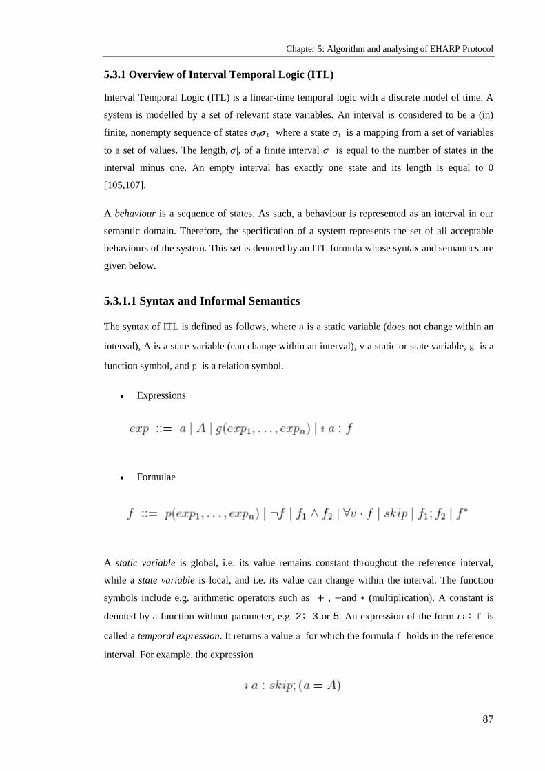
Chapter 5: Algorithm and analysing of EHARP Protocol
87
5.3.1 Overview of Interval Temporal Logic (ITL)
Interval Temporal Logic (ITL) is a linear-time temporal logic with a discrete model of time. A
system is modelled by a set of relevant state variables. An interval is considered to be a (in)
finite, nonempty sequence of states 𝜎0𝜎1 where a state 𝜎i is a mapping from a set of variables
to a set of values. The length,|𝜎|, of a finite interval 𝜎 is equal to the number of states in the
interval minus one. An empty interval has exactly one state and its length is equal to 0
[105,107].
A behaviour is a sequence of states. As such, a behaviour is represented as an interval in our
semantic domain. Therefore, the specification of a system represents the set of all acceptable
behaviours of the system. This set is denoted by an ITL formula whose syntax and semantics are
given below.
5.3.1.1 Syntax and Informal Semantics
The syntax of ITL is defined as follows, where a is a static variable (does not change within an
interval), A is a state variable (can change within an interval), v a static or state variable, g is a
function symbol, and p is a relation symbol.
Expressions
Formulae
A static variable is global, i.e. its value remains constant throughout the reference interval,
while a state variable is local, and i.e. its value can change within the interval. The function
symbols include e.g. arithmetic operators such as + , −and ∗ (multiplication). A constant is
denoted by a function without parameter, e.g. 2; 3 or 5. An expression of the form 𝜄 a: f is
called a temporal expression. It returns a value a for which the formula f holds in the reference
interval. For example, the expression

Chapter 5: Algorithm and analysing of EHARP Protocol
88
returns the value of the state variable A in the second state of the reference interval.
Atomic formulae are constructed using relation symbols such as = and≤. Formulae are
then constructed by composing atomic formulae with first order connectives (e.g.
⇁,∧,∀) and the temporal modalities skip (i.e. an interval of exactly two states), ―;‖
(Chop) and ―∗‖ (chop star).
5.3.1.2 Derived Constructs
The following constructs will be used for simplicity.
5.3.2 A formal Specification of EHARP Protocol
In ITL, a system state is modelled as a mapping from a finite set of variables to a set of values.
The system‘s behaviour is represented by a non-empty sequence of states, called an interval. A
variable whose value may change over time is called a state variable, while a variable whose
value does not change is called a static variable. In additional, we consider the so-called
memory variables, which behave exactly like variables in an imperative programming language
such as C, Pascal or FORTRAN. Unlike a state variable, a memory variable keeps its value until
it is explicitly assigned a new one. By convention, the name of a memory variable begins with
an uppercase letter (e.g. Td and Angle), that of a static variable begins with a lowercase letter
(e.g. n and src), while the name of a state variable begins with an underscore (e.g. _error). The
following variables are used to model the EHARP protocol.

Chapter 5: Algorithm and analysing of EHARP Protocol
89
5.3.2.1 Static Variables
The following static variables are used:
n: This is the number of nodes in the mobile ad hoc wireless network. Nodes are
numbered from 1 to n.
src: This denotes the source node. In equation 2, it is set to 1 to mean that node 1 is the
source node. Any other node can be chosen without having to modify any part of the
protocol specification.
dest: This denotes the destination node. In equation 2, it is set to n to mean that node n is
the destination node. Any node other than the source node can be used as the destination
node.
maxRReqCount: This is the maximum number of tries when the source node fails to
receive a route reply, for a timeout of Td (see section 4.2.3 for more details about Td).
Note that these are static variables and so their values do not change during the course of
the protocol.
5.3.2.2 State Variables
The following state variables are used:
_err: this variable is set to true when: (1) the source node has not received an
acknowledgement message from its neighbour after Tn seconds of sending to that
neighbour a route request message; or (2) the timeout Td has expired without the source
node receiving a route request reply. In both cases, this will trigger a new route request
being sent out by the source node if the number of tries has not reached the maximum
denoted by the static variable maxRReqCount (see equations 4 and 5).
_error: error[i] is set to false if the route request forwarded by an intermediate node i to one
of its neighbours has not been acknowledged after a timeout of Tn seconds (see next section
for more details about Tn).
_fRReq: fRReq[i] denotes the node that has forwarded the route request message to the
node i.
_Ack: Ack[i] denotes the node that has sent an acknowledgement message to the node i in
response to a route request message received from the node i.
5.3.2.3 Memory Variables
The following memory variables are used:

Chapter 5: Algorithm and analysing of EHARP Protocol
90
_Clock: This variable models a digital clock. It starts from 0 and increments by 1 at each
transition.
_RRep: This is true if a route has been found from source to destination, otherwise it is false.
_RReqCount: This counts the number of times the source node unsuccessfully tries to find a
route to a destination during the execution of the protocol.
_Tn: This is the timeout for finding a neighbour node and forwarding a route request to it.
_Td: This is the timeout for finding a route from source to destination.
_ Cache: Cache[i; k] is true if node k is in the neighbourhood of node i.
_ Angle: Angle[i] is the directional angle of the node i.
_SL: SL[i] is the link stability of the node i.
_RRL: This is the list of route records. Each route record has the form: node; angle; zone; Td;
SLi
_NLRR: This denotes the number of records in the RRL plus 1.
5.3.2.4 Formal Specification of EHARP
The protocol is described by the following formula
Where
Init () is a formula specifying the initial state of the protocol. The definition of Init ()
is given in Section 5.3.2.4.1.
Terminate states the termination conditions of the protocol. Its definition is given in
Section 5.3.2.4.2.
Node (i) is the specification of the node i. The definition of Node (i) is given in Section
5.3.2.4.3.

Chapter 5: Algorithm and analysing of EHARP Protocol
91
The formula (1) says that the protocol starts in a state satisfying Init () and involves n nodes that
run concurrently and cooperate to build a communication route between a source node and a
destination node.
5.3.2.4.1 System Initialisation: Init ()
Set all the initial values here:
5.3.2.4.2 System Termination: Terminate ()
Put all the invariants here:
5.3.2.4.3 Specification of Nodes: Node (i)
The source node performs the then and the intermediate nodes perform the else of the formula in
(4)

Chapter 5: Algorithm and analysing of EHARP Protocol
92
5.3.2.4.4 The source node performs:

Chapter 5: Algorithm and analysing of EHARP Protocol
93
5.3.2.4.5 The intermediate nodes perform:

Chapter 5: Algorithm and analysing of EHARP Protocol
94
5.4 Simulation Methodology and Model
In fact, most scenarios used in mobile ad hoc wireless networks and the behaviour of nodes in
the real world are still unknown, for two main reasons: the difficulty of predicting the dynamic
behaviour of such networks and the fact that they still exist mainly as a research subject, making
real-life measurements difficult and costly. Hence, simulation is often used to compare ad hoc
routing protocols. El-Nabi [97] elaborates:
―There are three different ways to model networks: formal analysis, real life measurements and
simulation [98]. The dynamic nature of ad hoc networks makes them hard to study by formal
analysis. Some formal techniques that have been used in static networks include Petri nets,
stochastic processes, queuing theory, and graph theory. None of these is especially well suited
to studying dynamic networks. Since ad hoc networks are still mainly a research subject, most
scenarios they will be used in are still unknown. For those scenarios that are known, e.g.
military networks, extreme uncertainties and dynamicity are expected. Thus, use of real life
measurements is currently almost impossible and certainly costly. The commonly used
alternative is to study the behaviour of the protocols in a simulated environment‖.
In addition, it is possible using simulation to evaluate and test the behaviour of networks with a
larger number of mobile nodes and different sizes of network area than might be possible with
physical devices in a fixed area. Moreover, it allows near perfect experimental control, testing
protocols under certain parameter values then rerunning the test while varying one experimental
variable and holding all others constant.
Many MANET researchers have simulated and evaluated their proposed systems using different
approaches and simulation tools. The most popular network simulators are the Network
Simulator NS-2 [89], the Global Mobile Information System Simulation Library GloMoSim
[92] and the OPNET Modeler [90], while some work has been simulated using programming
languages such as C, C++ and Java [75, 94].
5.4.1 Simulation Environment
This section reports the evaluation of the performance of the EHARP routing protocol by
extensive simulation using NS-2. What distinguishes NS-2 [99, 100] from other simulators is
the range of features it provides and the fact that it is an open source code that can be modified
and extended. NS-2 is a discrete event and object-oriented simulator intended for networking
research which was developed by the University of California at Berkeley and the VINT project
[97]. There are several different versions of NS-2, the latest being NS-2.34. NS-2 provides

Chapter 5: Algorithm and analysing of EHARP Protocol
95
substantial support for the simulation of TCP, routing and multicast protocols over wired and
wireless networks.
NS-2 is written in C++, with an Object Tool command language (OTcl) interpreter as a
command and configuration interface. The C++ part, which is fast to run but slower to change,
is used for detailed protocol implementation. The OTcl part, on the other hand, which runs
much more slowly, but can be changed very quickly, is used for simulation configuration. One
of the advantages of this split-language programming approach is that it allows for rapid
generation of large scenarios. One of the key hurdles to advancing MANET technologies from
single-tier, 2-D topology to multi-tier, 3-D topology is the lack of research tools that support 3-
D simulation and visualization [97]. For example, the wireless extension of NS-2 and Network
AniMator (NAM) [89], which have been among the most popular MANET research tools, lacks
3-D support. Ryu et al. [97] present a 3-D extension of NS-2 and NAM for mobile ad hoc
networks.
5.4.2 Parameter Values
In the simulation model, the number of mobile nodes ranges from 10 to 60, placed randomly
within the simulation area. Each simulation was executed for 250 seconds and the network
space for each simulation was 1 km x 1 km. The square site models situations in which nodes
can move freely around each other and where there is a small amount of path and spatial
diversity available for the routing protocol to discover and use. The network traffic was
modeled as 10 constant bit rate sources. All communication patterns were peer-to-peer and
connections were started at times uniformly distributed between 0 and 180 seconds (the
maximum value allowed in NS-2). TCP sources were not used in the simulation because of the
behaviour of TCP in offering a conforming load to the network by changing the times at which
it sends packets based on its perception of the network‘s ability to carry them. As a result, both
the time at which each data packet is originated by its sender and the position of the node when
sending the packet would differ between the protocols, preventing a direct comparison between
them. Table 5-1 provides a summary of the rest of the simulation parameters.

Chapter 5: Algorithm and analysing of EHARP Protocol
96
The results presented are mean values of multiple runs for each scenario and the collected data
were averaged over those runs.
Table 5.1: Parameters of simulation used with NS-2 and random waypoint
Scenario Name Mobility
Scenario
Speed
Scenario
Network Size
Scenario
Pause time (s) 0,50,100,200
,250
10 10
Max Node Speed
(m/s)
10 10,20,30,40,50,60 10
Number of mobile
nodes
50 50 10,30,50,60
Simulation Time (s) 250 250 250
Network Space 1 km x 1 km 1 km x 1 km 1 km x 1 km
Radio range 250 m 250 m 250 m
MAC Protocol IEEE 802.11 IEEE 802.11 IEEE 802.11
Radio propagation
model
Free space/
two-ray
Free space/
two-ray
Free space/
two-ray
Antenna model Omni
Antenna
Omni Antenna Omni Antenna
Traffic pattern CBR CBR CBR
Maximum number
of connections
10 10 10

Chapter 5: Algorithm and analysing of EHARP Protocol
97
5.5 Summary
In the proposed algorithm (EHARP), the use of HDA and the SL of nodes to select the most
robust and long-lived link between each two communicating nodes is investigated. In addition,
EHARP considers that the ad hoc wireless network lacks any external source of routing
information. Therefore, EHARP can be considered as a solution to handle the frequent changes
in the network topology due to mobility and to maintain the long-lived multi-hop paths between
two communicating nodes.

Chapter 6: Secure Enhanced Heading Direction Angle Routing Protocol
98
Chapter 6
Secure Enhanced Heading Direction Angle Routing Protocol
(SEHARP)
Objectives: to present
Our approach of (SEHARP)
The stages of (SEHARP)
Evaluating our using NS-2 base simulation
6.1 Introduction
The nodes in ad hoc wireless networks act both as regular terminals (source or destination) and
as routers for other nodes in the network, unlike fixed wired networks, such as the Internet,
where dedicated routers are controlled by a service provider. The provision of security becomes
a challenging task in these networks, owing to the absence of dedicated routers. The task of
ensuring secure communication in ad hoc wireless networks is difficult for reasons including
the mobility of nodes, limited processing power and limited availability of resources, such as
battery power and bandwidth.
Ad hoc wireless networks rely on the collaboration of the nodes involved for the network to
create itself and operate efficiently. While maintaining suitable routing information in a
distributed way is a challenging issue in such networks, it is even more challenging to secure the
protocols used for routing [1-20]. At the network level, an ad hoc network fundamentally
requires secure routing protocols, as these enable a communication path to be established. On
the other hand, most of the routing protocols [21-30] designed for these networks give no
consideration to security, operating with an implicit assumption of trust among the nodes. This
provides opportunities for malicious attacker‘s intent on bringing down the network. Many
types of routing protocol exist and have been extensively researched, with a view to finding
solutions to security vulnerabilities[22-30].
Our contribution presented in this chapter is to design a Secure Enhanced Heading-direction
Angle Routing Protocol (SEHARP) for ad hoc wireless networks based on the integration of
security mechanisms that could be applied to the EHARP routing protocol. It proposes a novel
secure routing protocol to improve the security level in ad hoc wireless networks, based on key

Chapter 6: Secure Enhanced Heading Direction Angle Routing Protocol
99
management and a secure path, which protects data to satisfy our security requirements. The
chapter is organized as follows: Section 6.2 reviews related work in ad hoc wireless networks;
Section 6.3 explains our security requirements; in Section 4 we propose an approach to
introduce a secure version of the EHARP routing protocol and Section 6.5 reports on its
evaluation. The chapter concludes with a summary.
6.2 Our Security Requirements
The following security requirements are to be satisfied by SEHARP.
Detection of malicious nodes: If there are malicious nodes in a network, then the secure
routing protocol should be able to detect them and avoid choosing such nodes during the routing
process.
Authentication: It is fundamental to verify the identity of an ad hoc wireless network node and
its fitness to access the network. In other words, nodes that wish to communicate with each
other must ensure that they are communicating with the right party and that they are genuine,
not impersonators. They must ensure that data is from the origin and not modified or falsified.
Authorisation: The nodes in ad hoc wireless networks need to have accurate authorisation in
order to access shared resources on the network. This ensures that only authorized nodes are
allowed to enter the network, store information and use it on their devices. In addition, RBAC
provides different priority levels, to guarantee that network elements and individuals can only
gain access to and perform operations on stored information, resources, services and
applications.
Confidentiality: The information that is sent between the ad hoc network nodes resident on
their devices, or related to their locations, needs to be protected. This is to ensure that the data
which has been sent between the nodes is the same and has not been modified, deleted or
retransmitted to another node or entity.
Availability: The availability of a network means that its essential services and applications
should be accessible at any time when they are needed, even in the event of a breach in security.
This availability ensures the survivability of the network, despite malicious attacks (denial of
service), or the misbehaviour of particular nodes. This requirement is especially important in ad
hoc wireless networks, where security breaches, attacks and malfunctions are more frequent and
less likely to be detectable.

Chapter 6: Secure Enhanced Heading Direction Angle Routing Protocol
100
Data integrity: The information that is exchanged between the nodes needs to be protected in
order to ensure that messages which have been sent are the same and have not been modified,
deleted or retransmitted to another node or entity. This is most fundamental in situations such as
banking, military operations and equipment controls (e.g. trains or planes), where such
modification or deletion could cause potential damage.
Non-repudiation: This ensures that any ad hoc wireless network node which sends/ receives a
message, or initiates a ‗not deny‘ on receiving/ sending packets to/ from other nodes, is genuine
and proves who the sender is. This is very important in situations of dispute or disagreement
over events. It can be achieved using techniques such as digital signatures that relate the data or
action to a signer.
Guarantee of secure correct route discovery: This ensures that the protocol is able to find the
route correctly and provide security for the selected route.
6.3 Our Approach
Our main focuses are to introduce SEHARP [102] to protect data transmission and to construct
a secure routing protocol. The network consists of a group of mutually trusting nodes. There are
two types of node, which are:
User Node (UN): Normal ground nodes, typically soldiers.
Network Backbone Node (NBBN): Usually units or master nodes located within the
network, for example tanks. NBBNs can establish direct wireless links for
communication amid themselves, as shown in Figure 6.1.
The network based on NBBNs is responsible for the key certificates and manages them. There
are four NBBNs in each network, because a defining characteristic of EHARP is that there
should be four head directions so that each has an NBBN. Our approach locates four NBBNs to
achieve our requirement for availability and non-repudiation.

Chapter 6: Secure Enhanced Heading Direction Angle Routing Protocol
101
0
NB
BN
90
180
270
NBBN
UN
UN
UN
UN
Figure 6.1: User nodes and network backbone nodes in a network
All user nodes should be able to run the encryption algorithms with limited computational
power. All UNs in the network should trust any data message or any message signed using the
corresponding private key. Each user node has enough memory to store information such as the
public keys and certificates of many other nodes.
SEHARP works as a group and has three stages, examined in turn in the remainder of this
section:
Distribution of keys and certificate stage.
Secure path stage.
Secure routing protocol stage.
6.3.1 Distribution of Keys and Certificate Stage
Our scheme adopts the NBBN approach because of its superiority in distributing keys and
achieving integrity and non-repudiation. The system uses private and public keys. The private
key is used to sign the certificate and the public key of all the nodes, while the public key is
used to renew certificates that are issued by another NBBN. All nodes must have a copy of the
NBBN‘s own public key to verify signatures. The public keys and the corresponding private
keys of all nodes are created by the NBBNs, which also issue the public-key certificates of all
nodes. Each node has its own public/private key pair. Public keys can be distributed to another
node in the secure path stage, while private keys should be kept confidential to individual nodes.

Chapter 6: Secure Enhanced Heading Direction Angle Routing Protocol
102
The NBBN signs the public key certificate for all nodes, so that these signings take place offline
before the nodes can enter the network.
Each node in our approach receives exactly one certificate after securely authenticating its
identity to the NBBN. Each node will hold its digital certificate in the Node Databases (NDB).
The main structure of node digital certificates, it contains the identifier of the node, its public
key, the name of the NBBN issuing this certificate, the certificate issue and expiry dates, and the
public key of the NBBN. Finally, the contents of the certificate will be attached to the digital
signature of the NBBN. All nodes in a network should maintain fresh certificates with the
NBBN. At the secure path stage, nodes use their certificates to authenticate themselves to other
nodes in the network.
6.3.2 Secure (node-to-node) Path Stage
Our approach is to use a public-key algorithm to establish secure paths between nodes. The
Secure Path Stage (SPS) is based on the requirement for all nodes to have a secure path with
other nodes before sending any route request packet. Any node receiving an RREQ from the
source node or another node without a secure path should discard the request. In our approach,
each node is given the system public key in order for any node to be able to send a Secure Path
Request (SPR) to another node the first time the certified public keys are exchanged. The
authenticity of the certificate can be confirmed as the nodes have the system public key. The
first objective of the SPS is the exchange of the certified public keys and their confirmation,
while its second objective is to ensure the identity of the sender before acceptance of the RREQ.
The SPS considers secure authentication node by node.
6.3.2.1 Source Node
When the source node S has an RREQ for node D, it looks for it in its route table, and then if it
finds it, acts as follows:
1- S will send an SPR specifying the type of packet (SRP), the IP address of the destination
(IPD), S‘s certificate (certS), all signed with S‘s private key.
2- D will verify the signature and certS.
3- If the signature and certS are validated, then D will send a Reply Secure Path Request
(RSPR), as shown in Figure 6.2. This will specify the type of packet (RSRP), the IP
address of the source (IPS), D‘s certificate (certD), all signed with D‘s private key, and it
will save certS in its NDB. If either is not validated, D will discard the request.

Chapter 6: Secure Enhanced Heading Direction Angle Routing Protocol
103
Figure 6.2: Secure path request and reply between nodes S and D
Otherwise, i.e. if S does not find D in the route table, S will send an SPR to a neighbouring
(intermediate) node specifying the type of packet, IPD and certS, all signed with S‘s private
key.
6.3.2.2 Intermediate Node
1- The intermediate node I will verify the signature and certS.
2- If these are validated, then I will send an RSPR specifying the type of packet, the IP address
of the source (IPs) and I‘s certificate (certI), all signed with I‘s private key, as shown in
Figure 6.3.
secure path request (SPR)(SRP,IPD,certS )
Reply secure path request (RSPR)(RSRP,IPS,certI )
Source node S
Intermediate node I
Figure 6.3: Secure path request and reply between nodes S and I
3- To make a secure path with its neighbour, node I will send an SPR to a neighbouring node
specifying the type of packet, IPD and certI, all signed with I‘s private key, as show in
Figure 6.4.

Chapter 6: Secure Enhanced Heading Direction Angle Routing Protocol
104
secure path request (SPR)(SRP,IPD,certI )
Intermediate node I
Neighbour node N
Figure 6.4: Secure path request from intermediate node
6.3.3 Secure Routing Protocol Stage
At this stage, our SEHARP approach uses a hybrid of security mechanisms so that it satisfies
the main security requirement and guarantees the discovery of a correct and secure route. The
security mechanisms that the protocol uses are the hash function, digital signature, time
synchronisation and route discovery request, each of which is now explained in turn.
6.3.3.1 Hash Function
The hash function is used to encrypt and update the data necessary for the routing process in
order to secure the mutable data, which in this case is the head direction and time to find a
destination, whose information uses hash chains.
SEHARP uses hash chains in order to secure the mutable data of the head direction and Td, the
maximum time to find a destination node, for any node in the network, including an
intermediate node and the destination node, which when it receives the message can verify that
the mutable data has not been decremented by any attacker. SEHARP forms a hash chain by
applying it one way.
A hash function is the operation whereby a node creates an RREQ or RREP and a hash function
repeatedly to begin. The setting of the hash function is as follows:
1. Assign a random number to the Hash field as the beginning value, so that Hash =
beginning.
2. Set the MaxHashCount field to the time to find destination value from the IP header, i.e.
MaxHashCount = Td.
3. The Hash_Function field is set to indicate which hash function is employed:
Hash_Function = h.

Chapter 6: Secure Enhanced Heading Direction Angle Routing Protocol
105
4. Calculate Top_Hash by hashing beginning value as _hash_Count.
- Top_Hash = h MaxHashCount – h hash_Count
- Hash Count = time to find neighbour
- Where h is a hash function and h j (y) is the result of applying the function h to y j
times.
When a node is retransmitted an RREQ or an RREP packet is used to verify the hash count. The
node performs the following operations:
1. It applies the hash function indicated by the Hash_Function field MaxHashCount minus
Hash Count to the beginning value in the Hash field and verifies that the value is equal
to the value contained in the Top_Hash field.
Top_Hash =(h MaxHashCount – h Hash_Count).
2. Before rebroadcasting an RREQ or forwarding a RREP, a node uses the hash function
from the Hash value for the new node: Hash = h (Hash).
6.3.3.2 Digital Signature
A digital signature is used to protect the non-mutable data, which is data not required or
changed in the routing process. Digital signatures provide authentication and data integrity and
ensure non-repudiation.
SEHARP has two digital signatures. The first is the source signature used to protect the integrity
of the non-mutable data in RREQ and RREP messages, which means that the source signs
everything. The second is the node-by-node signature, based on who obtained a secure path, and
every intermediate node afterwards verifies the hash function, updates information and provides
a signature for the updating. When a node receives an RREQ, it first verifies the signature of the
sender and of the secure path before creating or updating a route to that neighbour. Only if the
signature is verified will it update a route and set Td to find the neighbour. After it is updated, it
will sign all new updating and fields node by node from the RREQ. In the event of a failure, it
will discard the RREQ. The destination node, when it receives an RREQ, first verifies the
signature of the source and the signature of the intermediate node that has a secure path by field
signature node-to-node. In the event of a failure, the RREQ will be discarded.

Chapter 6: Secure Enhanced Heading Direction Angle Routing Protocol
106
6.3.3.3 Time Synchronisation
A timestamp is used to protect the route path from specific attacks. The EHARP protocol is
based on the time to find the destination and neighbouring nodes. When a node has a request
packet, it calculates the time to find a neighbour and destination, and after creating the packet
uses the timestamp; then the node that has received the packet must verify it from the
timestamp.
6.3.3.4 Route Discovery Request
Source node
To secure routing, the EHARP protocol has an additional secure suffix on the original message
format to carry out the expansion; its format is shown in Table 6.1.
Table 6.1: Secure suffix message format
TYPE Length Hash Function Max Hash Count
Top Hash
Source Signature
Timestamp
Node-to-Node Signature
Hash
In the table, the type of suffix field for a secure RREQ message has a value of 32, while for an
RREP message the value is 33. The suffix is lengthened for security in addition to type and
lengthening of the number of bytes outside the field. MaxHashCount field values from the
source node in the routing message are sent when randomly assigned. When these four fields are
accounted for by a byte store, the TopHash field value is equal to that of the MaxHashCount
field designated by the hash function to do the hash calculation.
Chapter 6: Secure Enhanced Heading Direction Angle Routing Protocol
107
When the source node sends a route request packet, SEHARP sets the MaxHopCount field
equal to the time to find the destination node (TD) field from the IP header; assigns a random
number and sets the hash field equal to it; and applies the hash function specified by the
corresponding MaxHashCount field multiplied by the random number, storing the calculated
result to the TopHash field. The source node also digitally signs all fields of the SEHARP
packet (except the HopCount domain) and the field before the global suffix of the message.
Node-to-node Signature intermediate node on the information stored signature, in RREQ source
node signature information, including the SEHARP packet (except the HopCount domain) and
the suffix field before the security message. Before signature the source node uses a timestamp.
Intermediate node
The signature line in the route discovery and route maintenance process occurs before sending
the routing information and before the beginning of the calculation. Intermediate nodes, on
receipt of an RREQ message, require secure authentication to activate. This process comprises
four steps:
(1) The TopHash value field is verified by comparing the result of the Hash function and so
on (MaxHashCount - HashCount) times the same hash result;
(2) Verification of the signature of the source node;
(3) Verification that the signature on the node-to-node is the owner‘s securing path;
(4) Verification of the timestamp. In the event of a failure the message is discarded.
The intermediate node, before forwarding messages to its neighbours, will re-sign carefully and
be used to replace the value of the node-to-node security suffix. The signature field must also be
updated before the Hash value, and its value will be equivalent to the original to provide a value
for computing Hash.
6.3.3.5 Route Reply
Destination node:
When the destination node has received the route request packet, it will verify three steps, i.e.
hash function, signatures and timestamp, and if all these are valid, it will update the information,
set the hash function and sign all information. The destination node will sign only in the node-
to-node signature field and send the message along the reverse path in the network, which is
determined by the nodes recorded.

Chapter 6: Secure Enhanced Heading Direction Angle Routing Protocol
108
Intermediate node:
If an intermediate node receives a route request message, it will check the security and if all
steps are valid it will accept the message; otherwise it will discard it. When it has information
about the destination node stored in its cache table (a valid path to the destination), then the
intermediate node will update and add its information. It will calculate and set the hash function
and sign all updated information, then sign in the node-to-node field and send the message
along the reverse path in the network, which is determined by the nodes recorded.
6.4 NS-2-Based Evaluation
This section reports on the testing of the performance of SEHARP in real network environments
using the NS-2 simulator. The simulation environments, parameter values and evaluation
metrics used in the experiments are presented and their results analysed.
6.4.1 Simulation Environment
The latest version of NS-2, version 2.34, was used to simulate the SEHARP algorithm. NS-2
simulator is installed in the Linux-based operating system the Fedora. In order to reduce the
effect of randomisation used in the simulation, each experiment was executed 25 times and the
average calculated. Therefore, the trace files containing the experimental results were very
large. They were filtered and sent to a Visual Basic tool in order to measure the evaluation
metrics. The mobility models generated and used in the experiments, Tcl scripts and trace files
were saved and will be provided for use with SEHARP.

Chapter 6: Secure Enhanced Heading Direction Angle Routing Protocol
109
6.5 Summary
This chapter has presented a secure routing protocol based on key management, a secure path
and protecting data to satisfy our security requirements. After understanding security
requirements and identifying the types of attack the network might face, we proposed the
security mechanism most able to satisfy these security requirements, having the following
elements:
asymmetric encryption (used to protect non-mutable data)
hash function (used to protect mutable data)
Time synchronisation.
All these mechanisms when applied to routing protocols should prevent external attacks,
including black holes and routing holes, while providing viability, confidentiality and
authentication. Time synchronization is used to provide the protocol with the ability to find the
route and to ensure that the selected route is the correct path. The digital signature mechanism,
when applied to routing protocols, should prevent internal attacks, including impersonation, and
should provide non-reputation and integrity.

Chapter 7: Security of Access in Hostile Environments Based on the History of Node in Ad hoc Networks
110
Chapter 7
Security of Access in Hostile Environments Based on the History
of Nodes in ad hoc Networks
Objectives: to present
Security requirements of secure environment
Classification in secure environment
Digital operation certificate management framework
Components of our architecture
Our secure environment formal description
Case study.
7.1 Introduction
An ad hoc wireless network is built on cooperation between two or more nodes with wireless
links and networking capability. The major applications of such networks today are tactical
military and other security-sensitive operations. For example, military and police units (e.g.
soldiers, tanks, police cars) equipped with wireless communication devices can form ad hoc
wireless networks when they roam in insecure environments. Such networks can also be used
for emergency, law enforcement and rescue missions. Since they have relatively low cost and
can be deployed rapidly, they also constitute a viable option for commercial uses such as sensor
networks and emergency situations, and there is a trend to adopt them for commercial uses due
to their unique properties. The most critical challenge in the design of these networks is their
security in hostile environments [81-86].
Their nodes are independent units which rely not on a central infrastructure but on neighbouring
nodes to route each packet to the destination node. Ad hoc wireless networks can therefore work
properly only if the participating nodes cooperate with each other in routing and forwarding.
Nodes lack physical protection and are always under threat of being captured and compromised.
They carry user and device histories, as each node can obtain data on all events involving a
specific user and a specific device; therefore, each has to be able to document the user and the
device at the registration stage.

Chapter 7: Security of Access in Hostile Environments Based on the History of Node in Ad hoc Networks
111
The security requirements for different services range from highly security-sensitive military
tactical operations, such as battlefields, rescue missions and emergency situations, to
instantaneous classroom applications and areas where density is too small to justify
economically the deployment of a network infrastructure. Attacks on ad hoc wireless networks
can come from any direction and can target any node. Thus, ensuring a secure environment is as
important as for wired networks, which have several lines of defence such as firewalls and
gateways. Security depends on access to the history of each unit, which is used to calculate the
cooperative values of each node in the environment. The calculated cooperative values are then
used by the relationship estimator to determine the status of the nodes. Every node should be
capable of making its own security decisions based on cooperation with other peer nodes.
The rest of the chapter is organized in the following manner. Section 7.2 discusses the
requirements for any security solution, while section 7.3 explains the secure environment.
Section 7.4 describes the creation of public/ private keys and digital certificates, section 7.5 sets
out the components of our architecture, section 7.6 presents and explains the activity diagram
and section 7.7 presents a case study. Section 7.8 concludes the chapter.
7.2 Security Requirements
The following are the security requirements to be met by a secure environment:
Authentication: Ensures the identity of the node with which the communication is
carried out. This avoids impersonation.
Availability: Ensures that the eligible nodes are able to obtain the required services
despite denial-of-service attacks.
Non-repudiation: Ensures that a node cannot deny a particular action performed by it at
a later stage. This could help in the detection of compromised nodes.
Detection of malicious nodes: Ensures that nodes are capable of detecting the presence
of malicious nodes in the environment, thus avoiding the participation of such nodes in
the routing process.
Stability: Ensures that a node is able to revert to its normal operating state within a finite
time after any attack.
7.3 Secure Environments
In a secure environment, some of the ad hoc nodes are involved in other infrastructure-based
wireless networks such as WLANs and cellular systems; therefore, each of the ad hoc nodes
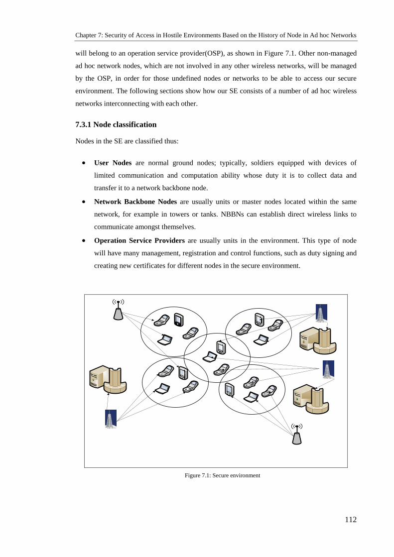
Chapter 7: Security of Access in Hostile Environments Based on the History of Node in Ad hoc Networks
112
will belong to an operation service provider(OSP), as shown in Figure 7.1. Other non-managed
ad hoc network nodes, which are not involved in any other wireless networks, will be managed
by the OSP, in order for those undefined nodes or networks to be able to access our secure
environment. The following sections show how our SE consists of a number of ad hoc wireless
networks interconnecting with each other.
7.3.1 Node classification
Nodes in the SE are classified thus:
User Nodes are normal ground nodes; typically, soldiers equipped with devices of
limited communication and computation ability whose duty it is to collect data and
transfer it to a network backbone node.
Network Backbone Nodes are usually units or master nodes located within the same
network, for example in towers or tanks. NBBNs can establish direct wireless links to
communicate amongst themselves.
Operation Service Providers are usually units in the environment. This type of node
will have many management, registration and control functions, such as duty signing and
creating new certificates for different nodes in the secure environment.
Figure 7.1: Secure environment

Chapter 7: Security of Access in Hostile Environments Based on the History of Node in Ad hoc Networks
113
7.3.2 Node Documentation
All nodes in the secure environment are also placed into three categories according to their
documentation status.
Documented nodes are those which are documented by the OSP. Information on these
nodes and their history is stored in a database (DB) authenticated by the OSP.
Certificate-documented nodes are those which possess a certificate issued by the OSP.
They will have come into contact with a secure environment earlier and the certificate
will verify that they are secure. Information on these nodes is stored in the documented
DB of the OSP and they do not have any history in the documented DB.
Undocumented nodes are those in the secure environment which do not fall into either
of the above two categories. This category may also contain nodes which could have been
certificate-documented by an OSP, but remain undocumented because there has been no
need to verify their certificates.
7.4 Digital Operation Certificate Management Framework
This section describes the certificate management system of a secure environment. It shows
how public/private keys and digital operation certificates are created. It also illustrates the
process of certificate revocation.
7.4.1 Creation of Public/ Private Keys and Digital Certificates
The public keys and the corresponding private keys of secure environment nodes are created by
the OSP, which also issues the public-key certificates of SE nodes. Since a key is unique,
(Kpublic) is unique and thus H(Kpublic), the fingerprint of Kpublic, is also unique and is considered
the identifier in an SE. The operation certificate is used as permission to access this
environment. Each node in the secure environment holds its digital operation certificate in its
node database. The main structure of digital operation certificates contains [70] the MAC
address of the node, its public key, the name of the OSP issuing this certificate, the certificate
issue and expiry dates and the public key of the OSP. Finally, the contents of the certificate are
attached to the digital signature of the OSP.
Node Identifier (ID): Holder of the certificate
MAC address of device (Mac): The unique serial number of the device
Node Public Key (Kpublic): A unique key that is the fingerprint of the user
Certificate Operation OSP Identifier: Name of the OSP that created and signed the
certificate

Chapter 7: Security of Access in Hostile Environments Based on the History of Node in Ad hoc Networks
114
Certificate Issue Date/Time: The first day on which the certificate is valid
Certificate Expiry Date/Time: The last day on which the certificate is valid
OSP Digital Signature: Digital signature of the OSP.
7.4.2 Digital Operation Certificate Distribution
Certificate distribution is a very important and low-cost mechanism that allows SE nodes to
send the certificates they hold. Each node periodically starts receiving its physical neighbour (in
one hop), its digital operation certificate and the corresponding OSP‘s public key stored in its
NDB. Each node receives these certificates, compares them with its NDB and adds whatever
new certificates it does not hold, as well as the public keys of its issuer; or it adds the renewal of
an expired, extant certificate. The certificate distribution process is repeated at regular time
intervals (RTIs). All nodes will have almost all digital operation certificates based on the
mobility of the nodes and the RTI.
7.4.3 Revocation of Digital Operation Certificates
The digital certificate management system provides certificate revocation as one of its basic
services. There are two types of certificate revocation in our algorithm. Explicit revocation
occurs when any node has a certificate and the OSP revokes it. The OSP sends the
corresponding revocation to the other nodes belonging to the SE. If it cannot send the
corresponding revocation for any reason, the renewal of the certificate can be denied, resulting
in an implicit revocation.
In general, the OSP, when issuing the certificate, determines its issuing and validity times. All
certificates are revoked after their expiration time. Therefore, the OSP should be updated about
the certificates of SE nodes before the expiration time. In both types of revocation, when the
OSP provides the SE nodes with information about any certificate, it should be distributed
through the exchange process. In this way the nodes in the secure environment will be provided
with this new information. Consequently, the OSP is responsible for the certificate revocation
process and for transferring these revocations to all SE nodes. All SE nodes are informed when
any of them carries out an explicit revocation and their NDBs are subsequently modified. This
revocation will be distributed to the other nodes in the secure environment, both by certificate
distribution and the process by which NDBs are merged.
The OSP is responsible for updating those certificates that have been implicitly revoked at
regular intervals. Each SE node that has a new certificate will update its NDB, and then transfer
the new certificate to its neighbours through the certificate distribution process. If any node

Chapter 7: Security of Access in Hostile Environments Based on the History of Node in Ad hoc Networks
115
does not receive the new certificate through the distribution and merging processes, and needs
to validate the key, a new certificate will be requested from the OSP itself.
7.5 Components of our Architecture
The components of our architecture are as follows:
User Nodes, as set out in 7.3.1 above, are typically soldiers or persons equipped with devices of
limited communication and computation ability, whose duty is to deal with nodes, collect data
and transfer them to NBBNs.
Network Backbone Nodes are usually units or master nodes located within the same network,
for example towers or tanks. NBBNs can establish direct wireless links for communication
among themselves. There are three divisions which carry out many functions (management,
observation, control and so on) for the network. Their responsibility is to collect data, to observe
nodes entering the network and to record the histories and certificates of all other nodes.
Operation Service Providers are usually units in the environment whose five divisions carry
out many functions (management, registration, control and so on) for that environment. Their
responsibility is to register new nodes, collect and analyse data, update the history of nodes and
observe nodes entering the environment. The OSP has six units, which are the Registration Unit
(RU), the Operation Certificate Unit (OCU), the Data Packet Collection Unit, the Analyser Unit
(AU), the History Model Unit and the Database Unit.
The responsibility of the Registration Unit is to register a new node and apply the policy of the
unit. Registration is an important stage before issuing a digital operation certificate for a node,
as it verifies the identity of the user. This is the function of the RU. The user provides the RU
with essential information: the user‘s name, the MAC address of the device and the fingerprint
of the user.
The Operation Certificate Unit is the main service provided by the OSP. When the OCU
receives a certification request from the RU, the OSP issues a digital operation certificate and
signs it with its private key. The structure of the certificate should be defined by being
standardised to ITU-T recommendation X.509, for example. All the information needed to
complete the certificate will be provided by the RU.

Chapter 7: Security of Access in Hostile Environments Based on the History of Node in Ad hoc Networks
116
DataBase (DB)
Monitoring
Packet (MP)
Node Database
(NDB)
Operation Service
Provider (OSP)
User Node (UN)
Registration
Unit (RU)
Operation
Certification
Unit (OCU)
Data Packets
Collect Unit
(DPCU)
Analyser
Unit (AU)
History
Model Unit
(HMU)
DataBase
Unit (DBU)
Network Backbone
Node (NBBN)
Figure 7.2: Components of our architecture
The Data Packet Collection Unit collects the data packets in a secure environment and saves
them in the main buffer. The data collector enables the packet analyser to use data collection
containers to analyse all available data that the system has collected from the different nodes. At
the same time it enables the packet analyser to process the transferred information, which can be
used to obtain and save data that is gathered from several sources [106].
The Database Unit stores information on each node in a secure environment, including
information regarding the history model of each node. It also keeps information like H (Kpublic),
Kpublic, the fingerprints of each node and the MAC address of each device. Finally, it holds
information regarding digital operation certificates and their revocation, to help in restricting
future access with the same certificate.

Chapter 7: Security of Access in Hostile Environments Based on the History of Node in Ad hoc Networks
117
The History Model Unit is used to calculate the cooperation values of each node in the
environment. Our secure environment access system uses the history of nodes to build several
lines of protection, equivalent to firewalls and gateways in wired networks. This unit receives
data on the classification of nodes from the analyser base to analyse the packets. There are three
kinds of node, as follows.
1) Positive Node (POSN). This is considered a cooperative node which, concerning packets
or messages, will:
- Notify its neighbours of any misbehaviour
- Send an update to its neighbours when it receives new information
- Forward any notification it receives from the OSP or NBBN
- Notify its neighbours about any problem occurring with itself.
The history of positive node (HPOSN) = Σ all events of (POSN )
Σ all events of node (1).
2) Natural Node (NATN). This is considered an uncooperative node and carries out normal
work, such as:
- Regular forwarding
- Sending regular updates to its neighbours
- Sending acknowledgment messages
The history of natural node (HNATN) = Σ all events of (NATA )
Σ all events of node. (2)
3) Negative Node (NEGN). This type misbehaves and does not send natural packets and
messages. It is not considered a natural node because it:
- Does not perform regular forwarding
- Does not send regular updates to its neighbours
- Does not send acknowledgment messages
- Carries out misbehaviour
- Tries to attack, for example by sending invalid certificates or invalid public keys, or
sending many packets to a specific node.
The history of negative node (HNEGN) = Σ all events of (NEGN )
Σ all events of node (3)
The Analyser Unit checks each packet or message in the secure environment that the main
buffer has collected. It then classifies all packets according to their contents. The analyser deals

Chapter 7: Security of Access in Hostile Environments Based on the History of Node in Ad hoc Networks
118
with all definition of packets and messages. It has the ability to define and classify unknown
packets and add to the classification. The analyser will classify the nodes in the secure
environment into three categories, POSN, NATN and NEGN, according to Table 7.1.
Table 7.1: Node classification by analyser unit
Event and behaviour Positive
Node Natural
Node Negative
Node
Regular forwarding √
Sends regular updates to its neighbours √
Sends acknowledgment messages √
Notifies its neighbours of any misbehaviour
by others √
Send updates to its neighbours when it
receives new information √
Forwards any notification it has received
from OSP or NBBN √
Notifies its neighbours of any problem
occurring with itself √
Carries out misbehaviour √
Tries to attack (sends invalid certificate or
invalid public key, or sends many packets to
a specific node) √
7.6 Activity Diagram
The activity diagram (Figure 7.3) depicts the steps taken by a node while handling requests to
access a secure environment. The following are the steps shown in the activity diagram:
- Request from node J to node I
- Node I checks whether node J is registered
- If node J is not registered and node I ignores its request then node J transfers to the
registration stage.

Chapter 7: Security of Access in Hostile Environments Based on the History of Node in Ad hoc Networks
119
- If node J is registered then node I checks for the operation certificate (OC) of node J in
its database.
- If the OC of node J is not in the database then node I requests it from the OSP.
- If the OC of node J is in the database then node I checks that the MAC address and public
key of node J are valid
- If the MAC address and public key of node J are not valid then node I ignores its request
and node J transfers to the registration stage
- If the MAC address and public key of node J are valid then Node I checks whether node
J is documented
- If node J is not documented, then it is certificated-documented
- If node J is certificated-documented then it can access the secure environment through
the OSP
- If node J is documented then node I requests the history of node J from the OSP.
- If the history of negative node of node J > 0 then Node J can access the secure
environment through the OSP
- If the HNEGN of node J < 0 then If the HPOSN of node J = 0 then Node J can access the
secure environment through an NBBN.
- ELSE node J can access the secure environment through any node.

Chapter 7: Security of Access in Hostile Environments Based on the History of Node in Ad hoc Networks
120
Figure 7.3: Activity diagram
The request from node J
Is node J REGISTERED? ?
Is node J OC in NDB of I
Is node J HPos = 0
Is node J HNEGN > 0
Is node J documented ?
Is node J Mac and public key = Mac and public key in NDB of node I
Registration unit
Request node J OC from OPS
Request node J H from OSP
node J is certificate - documented
node J accesses through any node J accesses through NBBN node
node J accesses through OSP
Resources of secure environment
Yes
Yes
Yes
Yes
No
Yes
N o
N o
No
No
Yes
NO
node node
Oc = Operation
certificate
NDB = node
database
Mac =Mac address
H =history file of
node
OSP= Operation
service provider
HNEGN= history
of negative node
HNATN= history
of natural node
HPOSN = history of
positive node

Chapter 7: Security of Access in Hostile Environments Based on the History of Node in Ad hoc Networks
121
7.7 Formal Description
The formal description of the Secure Environment (SE) is as follows.
7.7.1 Network model
In a secure environment, some of the ad hoc nodes are involved in other infrastructure-based
wireless networks such as WLANs and cellular systems; therefore, each of the ad hoc nodes
will belong to an operation service provider (OSP), as shown in Figure 7.1. Other non-managed
ad hoc network nodes, which are not involved in any other wireless networks, will be managed
by the OSP, in order for those undefined nodes or networks to be able to access our secure
environment. Our secure involves a number of MANET interconnecting with each other; in
addition all PKI are pre-connected by wireless connection to exchange data, and to update
information.
𝑃𝑘𝑖: Public key of network 𝑖, 1≤𝑖≤𝑛;
Those OSP are fully trusted by all nodes that belong to this secure environment. Nodes in the
SE are classified thus:
User Nodes(UN) are normal ground nodes;
𝑛: Number of networks in the SE; networks are numbered from 1 to 𝑛;
Network Backbone Nodes(NBBN) are usually units or master nodes located within the
same network,
𝑛𝑖: Number of nodes, including Network Back Bone Node (NBBN), in the network 𝑖, 1 ≤𝑖 ≤𝑛;
nodes in a network 𝑖 are numbered from 1 to 𝑛𝑖;
Operation Service Providers (OSP) is usually units in the environment.
k𝑖: Number of Operation Service Providers (OSPs) in SE 𝑖, 1≤ 𝑖 ≤𝑛;
𝑃𝑘𝑖: Public key of network 𝑖, 1≤𝑖≤𝑛;

Chapter 7: Security of Access in Hostile Environments Based on the History of Node in Ad hoc Networks
122
7.7.2 Behaviour model
In a secure environment, the behaviour of nodes capture by operating service node
(OSP) and stores in history file of behaviours that nodes might have (positive node ,
negative node and natural node ). Positive Node (POSN) This is considered a
cooperative node which, concerning packets or messages, will: Notify its neighbours of any
misbehaviour , Send an update to its neighbours when it receives new information,
Forward any notification it receives from the OSP or NBBN and Notify its neighbours
about any problem occurring with itself.
POSN: Positive node 𝑖 in the SE, for 1≤ 𝑖 ≤𝑛.
Natural Node (NATN), this is considered an uncooperative node and carries out normal
work, such as: Regular forwarding, Sending regular updates to its neighbours and sending
acknowledgment messages.
NATN: Natural node 𝑖 in the SE, for 1≤ 𝑖 ≤𝑛
Negative Node (NEGN),this type misbehaves and does not send natural packets and messages.
It is not considered a natural node because it: Does not perform regular forwarding, does not
send regular updates to its neighbours, does not send acknowledgment messages, carries out
misbehaviour, tries to attack, for example by sending invalid certificates or invalid public keys,
or sending many packets to a specific node.
NEGN: Negative node 𝑖 in the SE, for 1≤ 𝑖 ≤𝑛.
During specific period of time; this capture is always updated depending on the
observed node actions, despite the fact that saving all behaviours is impossible;
nevertheless, a reasonable number of behaviours must be stored.

Chapter 7: Security of Access in Hostile Environments Based on the History of Node in Ad hoc Networks
123
7.7.3 Mobility model
Our secure environment (SC) is proposed for ad hoc wireless networks with a minimum number
of mobile nodes. The proposed algorithm requires a different minimum number of nodes in the
network to guarantee establishment of connection between nodes. In secure environment (SC),
each node sends an RREQ packet to only one neighbor or operating service provider (OSP). In
an ad hoc network, however, there are many situations where mobile nodes move
together or form groups (the heading direction angle of nodes in each group is nearly
similar). For example, vehicles on a road or, in a military scenario, a group of soldiers
searching a particular plot of land, all working together in a cooperative manner to
accomplish a common goal.
The following variables represent the parameters of the SE:
𝑛: Number of networks in the SE; networks are numbered from 1 to 𝑛;
𝑛𝑖: Number of nodes, including Network Back Bone Node (NBBN), in the
network 𝑖, 1 ≤𝑖 ≤𝑛; nodes in a network 𝑖 are numbered from 1 to 𝑛𝑖;
k𝑖: Number of Operation Service Providers (OSPs) in SE 𝑖, 1≤ 𝑖 ≤𝑛;
hi : History of node in SE 𝑖, 1≤ 𝑖 ≤𝑛;
DOC𝑥𝑗: Digital Operation Certificate of node 𝑖 in the SE, for 1≤ 𝑖 ≤𝑛
DOCM : Documented of node 𝑖 in the SE, for 1≤ 𝑖 ≤𝑛
C-DOCM: Certificate -Documented of node 𝑖 in the SE, for 1≤ 𝑖 ≤𝑛
2POSN : Positive node 𝑖 in the SE, for 1≤ 𝑖 ≤𝑛
NATN : Natural node 𝑖 in the SE, for 1≤ 𝑖 ≤𝑛
NEGN : Negative node 𝑖 in the SE, for 1≤ 𝑖 ≤𝑛
HPOSN : History of positive node 𝑖 in the SE, for 1≤ 𝑖 ≤𝑛
HNATN : History of natural node 𝑖 in the SE, for 1≤ 𝑖 ≤𝑛
HNEGN : History of negative node 𝑖 in the SE, for 1≤ 𝑖 ≤𝑛
𝑃u𝑏𝑖𝑗: Public key of the node 𝑗 in the network 𝑖, for 1 𝑗 ≤𝑛𝑖 and 1≤𝑖≤𝑛;
𝑃𝑟v𝑖𝑗: Private key of the node 𝑗 in the network 𝑖, for 1 𝑗 ≤𝑛𝑖 and 1≤𝑖≤𝑛;
𝑃𝑘𝑖: Public key of network 𝑖, 1≤𝑖≤𝑛;

Chapter 7: Security of Access in Hostile Environments Based on the History of Node in Ad hoc Networks
124
MAC 𝑖: MAC address of node 𝑖, 1≤𝑖≤𝑛
Before defining our access mechanism, healthiness conditions for the above variables must be
defined.
𝑃𝑘𝑖𝑗≠𝑃𝑘𝑢𝑣 for 𝑖≠𝑢 or 𝑗≠𝑣
𝑃u𝑏𝑖≠ 𝑃u𝑏 𝑗 for 𝑖≠𝑗
𝑃𝑟v𝑖≠𝑃𝑟v𝑗 for 𝑖≠𝑗
MAC 𝑖≠ MAC 𝑗 for 𝑖≠𝑗
After showing the healthiness of our variables, our access mechanism can be described by the
following steps, where 𝑇𝑖 denotes the 𝑖th component of a tuple 𝑇:
1. Granting certificate and history authority duties to nodes:
∀𝑖,𝑗. 1≤𝑗≤𝑛𝑖 ∧ 1≤𝑖≤𝑛 ∧ OSP 𝑖𝑗=𝑡𝑖. (1)
2. Issuing digital operation certificates to local nodes of each network:
∀𝑖,𝑗. 1≤𝑗≤𝑛𝑖 ∧ 1≤𝑖≤𝑛 ∧ 𝐷O𝐶𝑥𝑖𝑗=<𝑗, 𝑖, 𝑠𝑑𝑥𝑖𝑗, 𝑒𝑑𝑥𝑖𝑗, OSP 𝑖, 𝑃𝑘𝑖𝑗, MAC 𝑖𝑗, CAL 𝑖𝑗 …, 𝑆𝑖𝑔n 𝑥𝑖𝑗>
(2)
Where OSP𝑖 is the OSP of the node 𝑗 in the network 𝑖; 𝑠𝑑𝑥𝑖𝑗 and 𝑒𝑑𝑥𝑖𝑗 are the start and end
date of the digital operation certificate; and the digital signature of the certificates 𝑆𝑖𝑔n 𝑥𝑖𝑗 is
calculated by the OSP𝑖 of the network 𝑖 by performing threshold cryptography. CAL𝑖𝑗 is the
type of node based on the registration.
3. Recording history certificate to local nodes of each network:
∀𝑖,𝑗. 1≤𝑗≤𝑛𝑖 ∧ 1≤𝑖≤𝑛 ∧ H𝑥𝑖𝑗=<𝑗, 𝑖, 𝑠h𝑥𝑖𝑗, uh𝑥𝑖𝑗, OSP𝑖, 𝑃𝑘𝑖𝑗, HPOSN 𝑖𝑗, HNATN 𝑖𝑗, HNEGN 𝑖𝑗,…
.…, CLLA 𝑖𝑗, 𝑆𝑖𝑔n𝑥𝑖𝑗> (3)
Where OSP𝑖 is the OSP of the node 𝑗 in the network 𝑖; 𝑠𝑑𝑥𝑖𝑗 and u𝑑𝑥𝑖𝑗 are the start and update
of the history file; HPOSN 𝑖𝑗, HNATN 𝑖𝑗 and HNEGN 𝑖𝑗 are the history file of the node and the
OSP of the network 𝑖 calculated from their events. CLLA 𝑖𝑗 is the kind of node that it will be
after calculation.

Chapter 7: Security of Access in Hostile Environments Based on the History of Node in Ad hoc Networks
125
Each node uses its digital operation certificate and history certificate in order to access services
in the SE through another node. A node needs to request from its OSP a new history certificate
and operation certificate in order to perform in it.
4. A request for digital certificates from a node 𝑗 of the network 𝑖 to another node can
be modelled by a message of the form:
𝒋, 𝒊,𝑾,𝒁 (4)
for some digital operation certificate 𝑊 and some history certificate 𝑍.
Such a request 𝑗, 𝑖,𝑊,𝑍 is checked as follows:
a) The requester is the owner of the digital operation and history certificates, i.e.
𝑾𝟏 = 𝒋 ∧ 𝒁𝟏 = 𝒋 ;
b) The OSP is the node where 𝑊 and 𝑍 were issued, i.e.
𝑾𝟐 = 𝒊 ∧ 𝒁𝟐 = 𝒊 ;
c) These certificates have not expired, i.e.
𝑾𝟑 ≤ 𝑪𝑫 ≤ 𝑾𝟒 ∧ 𝒁𝟑 ≤ 𝑪𝑫 ≤ 𝒁𝟒 ;
Where CD denotes the current date;
d) Certificates 𝑊 and 𝑍 are authenticated using the public key 𝑃𝑘𝑖 of the network 𝑖
and a signature verification algorithm for threshold cryptography.
5. The requester node can access services in SE as follows:
a) It has access through the OSP when the its history certificate is negative
H𝑥𝑖𝑗=<𝑗, 𝑖, 𝑠h𝑥𝑖𝑗, uh𝑥𝑖𝑗, OSP 𝑖, 𝑃𝑘𝑖𝑗, HPOSN 𝑖𝑗, HNATN 𝑖𝑗, HNEGN 𝑖𝑗….… HNEGN 𝑖𝑗,
𝑆𝑖𝑔n𝑥𝑖𝑗> (9)
negativeiHifOSPaccessiNode )()(
b) It has access through NBBN when its history certificate is natural
H𝑥𝑖𝑗=<𝑗, 𝑖, 𝑠h𝑥𝑖𝑗, uh𝑥𝑖𝑗, OSP 𝑖, 𝑃𝑘𝑖𝑗, HPOSN 𝑖𝑗, HNATN 𝑖𝑗, HNEGN 𝑖𝑗….… HNATN
𝑖𝑗, 𝑆𝑖𝑔n𝑥𝑖𝑗> (10)
naturaliHifNBBNaccessiNode )()(
c) It has access through any anther node when the its history certificate is positive

Chapter 7: Security of Access in Hostile Environments Based on the History of Node in Ad hoc Networks
126
H𝑥𝑖𝑗=<𝑗, 𝑖, 𝑠h𝑥𝑖𝑗, uh𝑥𝑖𝑗, OSP 𝑖, 𝑃𝑘𝑖𝑗, HPOSN 𝑖𝑗, HNATN 𝑖𝑗, HNEGN 𝑖𝑗….… HPOSN
𝑖𝑗, 𝑆𝑖𝑔n𝑥𝑖𝑗> (11)
postiveiHifjNodeaccessiNode )()()(
7.8 Case Study
Wireless ad hoc networks of networks (WANETs) are considered to be the future of wireless
networks owing to their specific characteristics: practicality, simplicity, self-organization, self-
configuration, ease of use and low cost when operating in a licence-free frequency band.
There are many applications of ad hoc networks, ranging from small, static networks that are
constrained by power sources, to large-scale, mobile, highly dynamic ones such as:
In education, for students to interact with teachers during classes via laptops
Healthcare and telecare systems
Inter-vehicle communications; for example, sending instant traffic reports and other
information between drivers
Email and electronic file transfer
Web services that can be used by ad hoc network users where a node in the network
serves as a gateway to the outside world
A wide range of military applications, such as a battlefield in unknown territory where an
infrastructure network is not available or impossible to maintain
Collaborative work for business environments
Emergency search-and-rescue operations in disaster areas, where it is almost impossible
to implement an infrastructure network
Personal area networking and Bluetooth
Electronic payments from anywhere (i.e. taxi)
Home wireless networks and smart homes
Office wireless networks.
In this section, we evaluate our secure environment system, concentrating on access to the SE.
A military case study with two scenarios will be introduced. The first highlights our secure
environment system, concentrating on our access control prevention technique for predefined
armies in an unknown and unstable military environment; this scenario combines
authentication, authorisation, confidentiality and integrity to provide privacy protection for
elements and tactics. The second scenario illustrates an SE system in an unstable and unknown

Chapter 7: Security of Access in Hostile Environments Based on the History of Node in Ad hoc Networks
127
military environment, showing event detection techniques combined with policies to provide a
secure military system against unknown elements.
7.8.1 Military environment
This military case study considers a battlefield in unknown territory, where infrastructure
deployment is hard to achieve or maintain; therefore, SE will be the perfect solution. The
military domain is a very challenging environment characterised by ambiguity and the need to
be able to deal with significant and disruptive dynamic changes. The goals of military systems
are mainly concerned with the ability to provide a secure environment for their components,
because opponents (enemies) are always trying their best to break down or destroy our
activities. Therefore, our secure environment concentrates on prevention and detection
mechanisms.
7.8.2 Definition of components
In the military environment, a critical system and the specification of the security requirements
for its components are essential. Registration, authentication and authorisation are among the
most important requirements, but before defining and analysing them, we need to define our
military system and its elements. We will be dealing with a military alliance consisting of
different armies (e.g. NATO [105]); each army will be defined as a WANET, while the whole
alliance is defined as an SE. Each of the armies comprises different elements, from a soldier to
the commander-in-chief. Usually in the military, there will be a specific hierarchy, in which
each officer will have the authority to give orders or to communicate with different elements
based on his/her rank.
Each army is classified as a WANET
WANETs merge to create a military alliance which is an SE
NATO is defined as the OSP for all armies
Soldiers in our SE will be defined as normal ad hoc nodes (negative, positive and nautral)
Base stations, tanks, trucks and military aircraft are defined as NBBNs
A set of policies is defined for each WANET (army).
7.8.3 Securing the Military Environment
Our military alliance will be a merger of different WANETs creating the SE, depicted in Figure
7.4.
The first step in providing a secure military system is to set up an operational process for the SE
components; this is done by distributing operation certificates, which are initially granted by the

Chapter 7: Security of Access in Hostile Environments Based on the History of Node in Ad hoc Networks
128
SE. These certificates act as identity documents for each element of the military SE. As with the
operation certificates, each OSP distribute certificates to enable specific nodes to carry out
leading and agile operations.
Figure 7.4: Secure environment community [105]
Two scenarios are now considered for the military environment.
7.8.4 Scenario One
The first scenario assumes a military alliance of two armies (British and French), each of which
has all kind of nodes (positive, negative and neutral). Before defining the SE to provide
authorisation and authentication to other nodes, a few points must be clarified in our scenario:
Armies can join and disconnect without affecting the SE system.
The public keys of the digital operation certificate are known between all elements in the
whole SE.
All nodes (soldiers) have received their operation certificates from their OSPs.
The OSPs have sent the history of the nodes to the NBBNs.
Each WANET has a set of policies.
All nodes in the SE must be registered at the registration stage.

Chapter 7: Security of Access in Hostile Environments Based on the History of Node in Ad hoc Networks
129
To provide a secure environment in this scenario, the first step is to ensure administration; as
previously mentioned, the OSP and the NBBNs will carry out the administration. Their duties
are to guarantee that elements from different armies can communicate and engage with different
elements in the SE system and to provide all nodes with updates on the history of other nodes.
The second step is to provide or prevent access to the most essential components, which are
needed in any community. Such prevention and access are needed for the authentication (by
operation certificate) and authorisation (by node history status) of the SE elements. For
instance, if a node (soldier) from the British army is trying to connect through the French army,
this node will be authenticated (verified) by the NBBN of the French army by his operation
certificate. Meanwhile, the granting of history status will be based on the policies (positive,
negative and natural) of the node to access the SE through the French army.
The third step is the containment and recovery component. When a problem has occurred
during any military operation, specific rules and procedures usually apply; for example, if
members of a French platoon have been captured, the enemy will try its best to extract the
private key in order to gain access to all secret information and to forge new certificates in order
to break the system down. In this situation, the OSP of the SE will try to regenerate new shares
of the private key, to make sure that it is kept safe during military operations. Moreover, the
history file of this node, updated via links through heterogeneous cards available with NBBNs
(e.g. satellites and cellular), will be used to receive orders from the main station OSP of the SE
to which the NBBN belongs.
To elaborate on our secure system and to show the components providing authentication and
authorisation between the military elements in the SE, the following specification formalism
will be introduced:

Chapter 7: Security of Access in Hostile Environments Based on the History of Node in Ad hoc Networks
130
𝑋𝑖 𝑗: soldiers 𝑖 from army 𝑗; 𝑖 ≥1; 𝑗 = NATO countries;
𝑌𝑖 𝑗: tanks, trucks and military aircraft 𝑖 from army 𝑗; 𝑖 ≥1; 𝑗 = NATO countries;
Zi: base station and cellular (OSP) 𝑖 from SE; 𝑖 ≥1.
DOCM: Documented node 𝑖 in the SE, for 1≤ 𝑖 ≤𝑛
POSN: Positive node 𝑖 in the SE, for 1≤ 𝑖 ≤𝑛
NATN: Natural node 𝑖 in the SE, for 1≤ 𝑖 ≤𝑛
NEGN: Negative node 𝑖 in the SE, for 1≤ 𝑖 ≤𝑛
HPOSN: History of positive node 𝑖 in the SE, for 1≤ 𝑖 ≤𝑛
HNATN: History of natural node 𝑖 in the SE, for 1≤ 𝑖 ≤𝑛
HNEGN: History of negative node 𝑖 in the SE, for 1≤ 𝑖 ≤𝑛
Hi: History certificate of node in SE 𝑖, 1≤ 𝑖 ≤𝑛;
DOC𝑥𝑗: Digital Operation Certificate of node 𝑖 in the SE, for 1≤ 𝑖 ≤𝑛
𝑃𝑘𝑖: public key of network 𝑖, 1≤𝑖≤𝑛;
MAC 𝑖: MAC Address of node 𝑖, 1≤𝑖≤𝑛
7.8.4.1 Authentication and authorisation between elements of an army in the
SE military system
Authentication (X1 British, X2 British) between soldiers in the same army is based on the X
operation certificate, where X is received from base station Z. The certificate will be
verified using the British public key and the MAC address of X.
𝐷O𝐶𝑥𝑖𝑗=<𝑗, 𝑖, 𝑠𝑑𝑥𝑖𝑗, 𝑒𝑑𝑥𝑖𝑗, OSP 𝑖, 𝑃𝑘𝑖𝑗, MAC 𝑖𝑗, CAL 𝑖𝑗 …, 𝑆𝑖𝑔n 𝑥𝑖𝑗>
ifreqdrop )( validBBXDOC ))21((
)21( BBX
validBBXDOCifreqAccept ))21(()(
Authorisation (X1 British, X2 British) between soldiers in the same army is based on the
history file of X and its status, where X is received from base station Z or Y and will be
granted only for positive X.
H𝑥𝑖𝑗=<𝑗, 𝑖, 𝑠h𝑥𝑖𝑗, uh𝑥𝑖𝑗, OSP 𝑖, 𝑃𝑘𝑖𝑗, HPOSN 𝑖𝑗, HNATN 𝑖𝑗, HNEGN 𝑖𝑗…CLLA 𝑖𝑗, 𝑆𝑖𝑔n𝑥𝑖𝑗>

Chapter 7: Security of Access in Hostile Environments Based on the History of Node in Ad hoc Networks
131
ifreqdrop )( positiveBBH )21(
)21( BBX
positiveHBifXaccessreqAccept )21()(
Authentication (Y1 British, Y2 British) between tanks or trucks in the same army is based on
the Y operation certificate, where Y is received from the base station Z. The certificate will
be verified using the British public key and MAC address of Y.
𝐷O𝐶𝑥𝑖𝑗=<𝑗, 𝑖, 𝑠𝑑𝑥𝑖𝑗, 𝑒𝑑𝑥𝑖𝑗, OSP 𝑖, 𝑃𝑘𝑖𝑗, MAC 𝑖𝑗, CAL 𝑖𝑗 …, 𝑆𝑖𝑔n 𝑥𝑖𝑗>
ifreqdrop )( validYBDOC ))21((
)21(YB
validYBDOCifreqAccept ))21(()(
Authorisation (Y1 British, Y2 British) between tanks or trucks in the same army is based on
the history file of Y and its status, where Y is received from base station Z and will be
granted only to positive and natural Ys.
H𝑥𝑖𝑗=<𝑗, 𝑖, 𝑠h𝑥𝑖𝑗, uh𝑥𝑖𝑗, OSP 𝑖, 𝑃𝑘𝑖𝑗, HPOSN 𝑖𝑗, HNATN 𝑖𝑗, HNEGN 𝑖𝑗…CLLA 𝑖𝑗, 𝑆𝑖𝑔n𝑥𝑖𝑗>
ifreqdrop )( negativeH )21(
)21(YB
negativeHifYaccessreqAccept )21()(
Authentication (Y1 British, X2 British) between tanks or trucks and soldiers from the same
army is based on Y and X operation certificates, where Y and X are received from base
station Z. The certificates will be verified using the British public key and MAC addresses
of Y and X.
𝐷O𝐶𝑥𝑖𝑗=<𝑗, 𝑖, 𝑠𝑑𝑥𝑖𝑗, 𝑒𝑑𝑥𝑖𝑗, OSP 𝑖, 𝑃𝑘𝑖𝑗, MAC 𝑖𝑗, CAL 𝑖𝑗 …, 𝑆𝑖𝑔n 𝑥𝑖𝑗>
ifreqdrop )( validYXDOC )(
YBXB
validYXDOCifreqAccept )()(

Chapter 7: Security of Access in Hostile Environments Based on the History of Node in Ad hoc Networks
132
Authorisation (Y1 British, X2 British) between tanks or trucks and soldiers in the same army
is based on the history files of Y and X and their status, where Y is received from base
station Z, and will be granted only to positive and natural Ys or Xs.
H𝑥𝑖𝑗=<𝑗, 𝑖, 𝑠h𝑥𝑖𝑗, uh𝑥𝑖𝑗, OSP 𝑖, 𝑃𝑘𝑖𝑗, HPOSN 𝑖𝑗, HNATN 𝑖𝑗, HNEGN 𝑖𝑗…CLLA 𝑖𝑗, 𝑆𝑖𝑔n𝑥𝑖𝑗>
ifreqdrop )( negativeYXH )(
YBXB
negativeYXHifYXaccessreqAccept )()(
7.8.4.2 Authentication between elements from different armies in the SE
military system
Authentication (X1 British, X1 French). If a soldier from the British army wants to
authenticate a French soldier, this will be done using the operation certificate, which will be
verified using the French public key and the MAC address of X.
𝐷O𝐶𝑥𝑖𝑗=<𝑗, 𝑖, 𝑠𝑑𝑥𝑖𝑗, 𝑒𝑑𝑥𝑖𝑗, OSP 𝑖, 𝑃𝑘𝑖𝑗, MAC 𝑖𝑗, CAL 𝑖𝑗 …, 𝑆𝑖𝑔n 𝑥𝑖𝑗>
ifreqdrop )( validXBDOC )(
XF
validXBDOCifreqAccept )()(
Authorisation (X1 British, X1 French). If a British soldier tries to communicate with a
French soldier, then the latter will need to check the history which he receives from the OSP
or a French NBBN. If the British X is a positive node it will be allowed to communicate
directly with the French soldier, while if it is a natural node it will be allowed to do so
through a French NBBN.
H𝑥𝑖𝑗=<𝑗, 𝑖, 𝑠h𝑥𝑖𝑗, uh𝑥𝑖𝑗, OSP 𝑖, 𝑃𝑘𝑖𝑗, HPOSN 𝑖𝑗, HNATN 𝑖𝑗, HNEGN 𝑖𝑗…CLLA 𝑖𝑗, 𝑆𝑖𝑔n𝑥𝑖𝑗>
ifreqdrop )( negativeXBH )(
XF naturalXBHifNBBNaccessreqAccept )()(
positiveXBHifXFaccessreqAccept )()(

Chapter 7: Security of Access in Hostile Environments Based on the History of Node in Ad hoc Networks
133
Authentication (Y1 British, Y1 French). If tanks or trucks from the British army want to
authenticate a French tank, this will be done using the operation certificate, which will be
verified using the French public key and the MAC address of Y.
𝐷O𝐶𝑥𝑖𝑗=<𝑗, 𝑖, 𝑠𝑑𝑥𝑖𝑗, 𝑒𝑑𝑥𝑖𝑗, OSP 𝑖, 𝑃𝑘𝑖𝑗, MAC 𝑖𝑗, CAL 𝑖𝑗 …, 𝑆𝑖𝑔n 𝑥𝑖𝑗>
ifreqdrop )( validYBDOC )(
)(FY
validYBDOCifreqAccept )()(
Authorisation (Y1 British, Y1 French). If a British tank tries to communicate with a French
one, the history of the British Y is required and can be received from the OSP. If the British
Y is a positive or natural node it is allowed to communicate with French tanks, whereas if it
is a negative node it can do so only through the OSP of the SE.
H𝑥𝑖𝑗=<𝑗, 𝑖, 𝑠h𝑥𝑖𝑗, uh𝑥𝑖𝑗, OSP 𝑖, 𝑃𝑘𝑖𝑗, HPOSN 𝑖𝑗, HNATN 𝑖𝑗, HNEGN 𝑖𝑗…CLLA 𝑖𝑗, 𝑆𝑖𝑔n𝑥𝑖𝑗>
negativeYFHifOSPaccessreqAccept )()(
)(FY
naturalpostiveYBHifNBBNaccessreqAccept )()(
Authentication (Y1 British, X1 French). If a British tank wants to authenticate a French
soldier, this will be done using the operation certificate, which will be verified using the
French public key and the MAC address of Y.
𝐷O𝐶𝑥𝑖𝑗=<𝑗, 𝑖, 𝑠𝑑𝑥𝑖𝑗, 𝑒𝑑𝑥𝑖𝑗, OSP 𝑖, 𝑃𝑘𝑖𝑗, MAC 𝑖𝑗, CAL 𝑖𝑗 …, 𝑆𝑖𝑔n 𝑥𝑖𝑗>
ifreqdrop )( validYBDOC )(
)(FX
validYBDOCifreqAccept )()(
Authorisation (Y1 British, X1 French). If a British tank tries to communicate with a French
soldier, a history of the British Y is required and can be received from the OSP. If the
British Y is a positive or natural node it is allowed to communicate with French tanks,
whereas if it is a negative node it can do so only through the OSP of the SE.

Chapter 7: Security of Access in Hostile Environments Based on the History of Node in Ad hoc Networks
134
H𝑥𝑖𝑗=<𝑗, 𝑖, 𝑠h𝑥𝑖𝑗, uh𝑥𝑖𝑗, OSP 𝑖, 𝑃𝑘𝑖𝑗, HPOSN 𝑖𝑗, HNATN 𝑖𝑗, HNEGN 𝑖𝑗…CLLA 𝑖𝑗, 𝑆𝑖𝑔n𝑥𝑖𝑗>
negativeYBHifOSPaccessreqAccept )()(
)(FX
naturalpostiveYBHifNBBNaccessreqAccept )()(
7.8.5 Scenario Two
As with the first scenario, scenario two assumes a military alliance consisting of two armies
(British and French). In addition, new elements will be defined in this scenario (Japanese army).
Before stating how the SE provides authorisation and authentication to other nodes, some points
must be clarified:
Armies can join and disconnect without affecting the SE system.
The public keys of the digital certificates are known by British and French elements in
the whole SE system and unknown to the Japanese army.
All nodes (soldiers and tanks) have received their operation certificates from their own
OSPs (each army has its own certificate).
Any node that is undefined and trying to operate in a different network will receive an
operation certificate from its OSP and its history file will be new.
The OSP sends node histories NBBNs.
Each WANET has a set of policies.
To illustrate the working of the SE system and to show how the authentication and authorisation
components operate between the military elements, the following example is introduced. If
during a war the British army needs reinforcements from a non-NATO country such as Japan, in
order for the Japanese army to communicate with British forces and to engage into the
battlefield, Japanese soldiers and tanks will need to obtain an operation certificate from the OSP
to perform in such situations. As Japanese forces are non-trusted, our OSP will monitor and
observe their actions based on their history in order to check whether or not Japanese elements
are acting in a normal or malicious manner. This checking is accomplished by tracing their
behaviour. Usually, showing all aspects of the tracing of behaviour under the set of policies in
our scenario is impossible; therefore, we provide examples showing normal, malicious and
positive actions.
The following specific formalism is introduced:

Chapter 7: Security of Access in Hostile Environments Based on the History of Node in Ad hoc Networks
135
𝑋𝑖 𝑗: soldiers 𝑖 from army 𝑗; 𝑖 ≥1; 𝑗 = NATO countries;
𝑌𝑖 𝑗: tanks, trucks and military aircraft 𝑖 from army 𝑗; 𝑖 ≥1; 𝑗 = NATO countries;
Z: base station and cellular (OSP) 𝑖 from SE 𝑖 ≥1;
W 𝑖k: soldiers 𝑖 from army k; 𝑖 ≥1; k = non-NATO country;
M ik: tanks, trucks and military aircraft 𝑖 from army k; 𝑖 ≥1; k = non-NATO country.
In the first instance, the Japanese will deal with the OSP. Four examples, all set in wartime, are
given below to show how the OSP observes the behaviour of new nodes and the new army to
build a history for every node as a basis for granting authorisation.
In the first example, if an order from an OSP has been given to Japanese troops and the soldiers
obey this order, the OSP will observe these acts and decide whether or not they are normal; it
will still classify the nodes as new and follow these rules:
Authentication (W1 Japanese, X1 French). If a soldier from the Japanese army wants to
authenticate a French soldier in the SE, this will be done using the operation certificate,
which will be verified using the OSP‘s public key and the MAC address of W.
𝐷O𝐶𝑥𝑖𝑗=<𝑗, 𝑖, 𝑠𝑑𝑥𝑖𝑗, 𝑒𝑑𝑥𝑖𝑗, OSP 𝑖, 𝑃𝑘𝑖𝑗, MAC 𝑖𝑗, CAL 𝑖𝑗 …, 𝑆𝑖𝑔n 𝑥𝑖𝑗>
ifreqdrop )( validWJDOC )(
)(FX
validWJDOCifreqAccept )()(
Authorisation (W1 Japanese, X1 French). If a Japanese soldier tries to communicate with a
French one, the latter will need to check his history, which he obtains from the OSP or a
French NBBN; if the Japanese W is a new node from a new army it will be allowed to
communicate with the French soldier through the OSP.
H𝑥𝑖𝑗=<𝑗, 𝑖, 𝑠h𝑥𝑖𝑗, uh𝑥𝑖𝑗, OSP 𝑖, 𝑃𝑘𝑖𝑗, HPOSN 𝑖𝑗, HNATN 𝑖𝑗, HNEGN 𝑖𝑗…CLLA 𝑖𝑗, 𝑆𝑖𝑔n𝑥𝑖𝑗>
ifreqdrop )( DOCMWJH )(
XF
DOCMWJHifOSPaccessreqAccept )()(

Chapter 7: Security of Access in Hostile Environments Based on the History of Node in Ad hoc Networks
136
In the second example, if an order from an OSP has been given to Japanese troops and the
soldiers obey it, the OSP will observe these acts and decide whether or not they are normal. If
the node continues to obey every order the OSP will classify is as neutral and follows these
rules:
Authentication (W1 Japanese, X1 French). If a Japanese soldier wants to authenticate a
French one in the SE, this will be done using the operation certificate, which will be
verified using the OSP‘s public key and the MAC address of W1.
𝐷O𝐶𝑥𝑖𝑗=<𝑗, 𝑖, 𝑠𝑑𝑥𝑖𝑗, 𝑒𝑑𝑥𝑖𝑗, OSP 𝑖, 𝑃𝑘𝑖𝑗, MAC 𝑖𝑗, CAL 𝑖𝑗 …, 𝑆𝑖𝑔n 𝑥𝑖𝑗>
ifreqdrop )( validWJDOC )(
)(FX
validWJDOCifreqAccept )()(
Authorisation (W1 Japanese, X1 French). If a Japanese soldier tries to communicate with a
French one, the latter will need to check his history, which he obtains from the OSP or a
French NBBN; if the Japanese W is a natural node it is allowed to communicate with the
French soldier through a French NBBN.
H𝑥𝑖𝑗=<𝑗, 𝑖, 𝑠h𝑥𝑖𝑗, uh𝑥𝑖𝑗, OSP 𝑖, 𝑃𝑘𝑖𝑗, HPOSN 𝑖𝑗, HNATN 𝑖𝑗, HNEGN 𝑖𝑗…CLLA 𝑖𝑗, 𝑆𝑖𝑔n𝑥𝑖𝑗>
ifreqdrop )( DOCMWJH )(
XF DOCMWJHifOSPaccessreqAccept )()(
naturalWJHifNBBNaccessreqAccept )()(
In the third example, if an order and notification from an OSP has been given to Japanese troops
and the soldiers obey this order and forward the notification to their neighbours, then the OSP
will observe these acts and decide that they are positive. If the node continues to obey all orders
and forward all notifications, the OSP will classify it as a positive node and follow these rules:
Authentication (W1 Japanese, X1 French). If a Japanese soldier wants to authenticate a
French soldier in the SE, this will be done using the operation certificate, which will be
verified using the OSP‘s public key and the MAC address of W1.

Chapter 7: Security of Access in Hostile Environments Based on the History of Node in Ad hoc Networks
137
𝐷O𝐶𝑥𝑖𝑗=<𝑗, 𝑖, 𝑠𝑑𝑥𝑖𝑗, 𝑒𝑑𝑥𝑖𝑗, OSP 𝑖, 𝑃𝑘𝑖𝑗, MAC 𝑖𝑗, CAL 𝑖𝑗 …, 𝑆𝑖𝑔n 𝑥𝑖𝑗>
ifreqdrop )( validWJDOC )(
)(FX
validWJDOCifreqAccept )()(
Authorisation (W1 Japanese, X1 French). If a Japanese soldier tries to communicate with a
French one, the latter will need to check his history, which he obtains from the OSP or a
French NBBN. If the Japanese W is a positive node it is allowed to communicate directly
with the French soldier.
H𝑥𝑖𝑗=<𝑗, 𝑖, 𝑠h𝑥𝑖𝑗, uh𝑥𝑖𝑗, OSP 𝑖, 𝑃𝑘𝑖𝑗, HPOSN 𝑖𝑗, HNATN 𝑖𝑗, HNEGN 𝑖𝑗…CLLA 𝑖𝑗, 𝑆𝑖𝑔n𝑥𝑖𝑗>
ifreqdrop )( DOCMWJH )(
XF naturalWJHifNBBNaccessreqAccept )()(
positiveWJHifXFaccessreqAccept )()(
In the fourth example, a Japanese soldier tries to request a specific tactic from the French army
in the SE using an invalid or fake operation certificate. The OSP will observe this act, decide
that it is negative and send an update for the history file to all nodes in the SE. If the node
continues to behave in this way, the OSP will classify it as a negative node and adopt the
following rules:
Authentication (W1 Japanese, X1 French). If a Japanese soldier wants to authenticate a
French one in the SE, this will be done using the operation certificate, which will be
verified using the OSP‘s public key and the MAC address of W1.
𝐷O𝐶𝑥𝑖𝑗=<𝑗, 𝑖, 𝑠𝑑𝑥𝑖𝑗, 𝑒𝑑𝑥𝑖𝑗, OSP 𝑖, 𝑃𝑘𝑖𝑗, MAC 𝑖𝑗, CAL 𝑖𝑗 …, 𝑆𝑖𝑔n 𝑥𝑖𝑗>
ifreqdrop )( validWJDOC )(
)(FX
validWJDOCifreqAccept )()(

Chapter 7: Security of Access in Hostile Environments Based on the History of Node in Ad hoc Networks
138
Authorisation (W1 Japanese, X1 French). If a Japanese soldier tries to communicate with a
French one, the latter will need to check his history, which he obtains from the OSP or a
French NBBN. If the Japanese W is a negative node it will not be allowed to communicate
directly with the French soldier.
H𝑥𝑖𝑗=<𝑗, 𝑖, 𝑠h𝑥𝑖𝑗, uh𝑥𝑖𝑗, OSP 𝑖, 𝑃𝑘𝑖𝑗, HPOSN 𝑖𝑗, HNATN 𝑖𝑗, HNEGN 𝑖𝑗…CLLA 𝑖𝑗, 𝑆𝑖𝑔n𝑥𝑖𝑗>
ifreqdrop )( negativeWJH )(
XF
negativeWJHifNBBNaccessreqAccept )()(

Chapter 7: Security of Access in Hostile Environments Based on the History of Node in Ad hoc Networks
139
7.9 Summary
This chapter has proposed ways to control access to a secure ad hoc database environment
based on the history of its nodes. It also proposes an access algorithm which explains the steps
taken by a node while handling requests to access a secure environment.
We have provided a case study, with specific concentration on two military scenarios in
unknown and insecure territory. Scenario one assumed two NATO countries (pre-connected) in
a battlefield and showed the implementation and evaluation of access to a secure environment
providing authentication and authorisation between members of the same network and between
other members. Scenario two considered two NATO countries with new elements (non-
defined), showing the implementation and evaluation of our mechanism for allowing and
preventing access to the secure environment. It detailed the access technique between NATO
countries and the undefined elements, presenting a number of different situations that any
military system might experience. In each situation our technique was examined to establish
whether or not the situation was adequately addressed by our set of policies in order to prevent
malicious acts by undefined elements in a secure military environment.
The solution is a combination of the history of the nodes and operation certificates. Each node
in a secure environment is uniquely identified by its public key and MAC address. The solution
addresses various vulnerability issues affecting wireless links such as active and passive attacks.
The dynamic nature of networks and their membership does not affect the solution, since each
node makes access decisions on its own and the use of cooperative algorithms is avoided.

Chapter 8: Comparative Analysis of Routing Protocols
140
Chapter 8
Comparative Analysis of Routing Protocols
Objectives: to present
Compare results and analysis of EHARP and HARP
Compare results and analysis of SEHARP and EHARP
8.1 Introduction
This chapter presents a quantitative analysis comparing the performance of our
proposed algorithms. There are two sections, the first giving the results of detailed
simulations and a comparative analysis of the relative performance of two protocols:
EHARP and HARP. The second section compares the performance of EHARP with that
of SEHARP.
The protocols were carefully implemented in the NS-2 network simulator
according to the specifications and guidance for implementing new routing
algorithms issued by its designers. The particular parameters and values that were
chosen when implementing each algorithm in the network simulator are
described.
8.2 Results and Comparative Analysis of EHARP and HARP
This section consists of two main parts; the first presenting the performance metrics used for
evaluating and comparing the performance of the routing algorithms, while the second offers a
comparative overview and an analysis of these comparisons.

Chapter 8: Comparative Analysis of Routing Protocols
141
8.2.1 Performance Metrics
The performance metrics used for the comparison are the same as those used for
evaluating the EHARP, HARP algorithms.
We measured three key parameters to evaluate the performance of our:
The efficiency of data packet delivery is defined as the measured ratio of the
number of data packets delivered to their destinations to the number of all packets
generated in the network. Note that each time a packet is forwarded this is
counted as one packet transmission.
Route discovery packets (overhead) are defined as the number of all packets
generated by all nodes in the network in order to establish routes between sources
and destinations.
Average end-to-end delay of transferred data packets includes all possible delays
caused by buffering during route discovery, queuing at the interface-queue and
retransmission delays at the medium access control layer..
Each parameter metric mentioned above was simulated in three different scenarios:
1) Mobility scenario: with elapsed time values,
2) Speed scenario: with different node speeds,
3) Network size scenario: with different numbers of nodes.
8.2.2 Comparative Overview and Analysis
This section highlights the performance parameters used for comparing our proposed algorithms
with the HARP protocol.

Chapter 8: Comparative Analysis of Routing Protocols
142
8.2.2.1 Route Discovery Packets (overhead)
Figure 8.1 is a chart of route discovery packets through out the simulation period with
the information captured at 50 sec and interval. The number of route discovery packets
needed to find the path under EHARP and HARP increase and is shown in the chart. It
can be seen that the number of route discovery packets needed to find the path is much
lower in EHARP than in the HARP protocols, because the node under EHARP selects
only that one node which has the greatest value of link stability to transmit the request
packet.
The increase is shown in Table 8.1, as a percentage and this is affected by many factors:
the number of intermediate nodes, the location of source and destination, the number of
attempts to reach the destination, the dropping of packets and the range of radio
frequency (RF). The maximum percentage is 24.4% and the minimum is 13.3%. Based
on the chart, the minimum percentage occurs when for example the source and
destination are close together thus the number of intermediate nodes will be the
minimum and the number of attempts to reach the destination will be the minimum. The
maximum percentage occurs when for example the source and destination are not close
together thus the number of intermediate nodes will be the maximum and the number of
attempts to reach the destination will be the maximum.
Table 8.1: Percentage of increase against period of simulation
Period of simulation (s) Percentage of increase
0–50 22.2%
50–100 17.7%
100–150 13.3%
150–200 22.2%
200–250 24.4%

Chapter 8: Comparative Analysis of Routing Protocols
143
Figure 8.1: Route discovery vs. mobility (elapsed time)
The impact of node speeds on the route discovery packets for our scheme is shown in
Figure 8.2, which plots route discovery against speed of node movement. As speed
increases, the number of route discovery packets generated by EHARP and HARP
increases, because the locations of source and destination are changed; thus the number
of attempts to reach the destination will be the maximum. Route discovery packets in
our scheme are significantly fewer than this generated by HARP because when
establishing routes, in all situations, the source and intermediate nodes under EHARP
select a limited number of nodes to contribute to finding these routes.
0
10000
20000
30000
40000
50000
60000
50 100 150 200 250
The
Ro
ute
dis
cove
ry p
acke
ts
Elapsed time (s)
The Route discovery packets (Overhead)
HARP
EHARP

Chapter 8: Comparative Analysis of Routing Protocols
144
Figure 8.2: Route discovery vs. speed
Figure 8.3: Route discovery vs. network size
0
5000
10000
15000
20000
25000
10 20 30 40 50
The
Ro
ute
dis
cove
ry p
acke
ts
Node speed
The Route discovery packets
HARP
EHARP
0
5000
10000
15000
20000
25000
30000
35000
40000
10 20 30 40 50
The
Ro
ute
dis
cove
ry p
acke
ts
Network size (node)
The Route discovery packets
HARP
EHARP

Chapter 8: Comparative Analysis of Routing Protocols
145
The scalability of mobile ad hoc networks with the number of nodes is shown in Figure
8.3, which displays the results of an experiment examining the effect on numbers of
route discovery packets of changes in the number of mobile nodes. As can be seen in
Figure 8.3, as the number of nodes in the network was increased, the number of route
discovery packets generated by EHARP and HARP also increased, because the source
and destination were not close together; thus the number of intermediate would be the
maximum. Our scheme has fewer the number of route discovery packets than HARP
because the nodes under EHARP select only those nodes which have strongest link to
transmit the request packet.
. Consequently, it can be seen that our proposed scheme is more scalable with the
network size in terms of overhead cost than HARP and that the number of route
discovery packets is less affected by mobility, node speed and network size than in
either of this.
8.2.2.2 Efficiency of Data Packet Delivery
Figures 8.4, 8.5 and 8.6 compare the efficiency of our proposed scheme with HARP a
by plotting ERDP against mobility for elapsed times, node speeds and network size. In
general, these figures show that the ERDP in our scheme is higher than for HARP in
terms of elapsed time, speed and number of nodes. This means that fewer of the number
of route discovery packets are needed to deliver data packets from source to destination,
because long-lived routes are established.
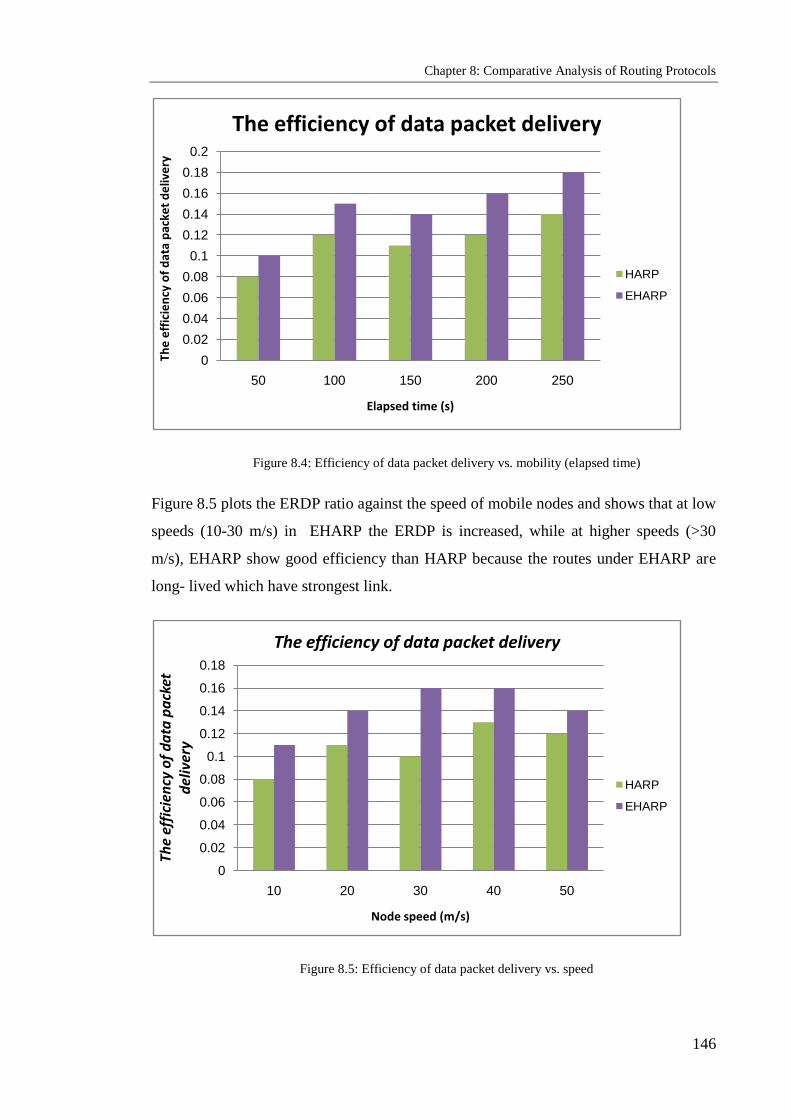
Chapter 8: Comparative Analysis of Routing Protocols
146
Figure 8.4: Efficiency of data packet delivery vs. mobility (elapsed time)
Figure 8.5 plots the ERDP ratio against the speed of mobile nodes and shows that at low
speeds (10-30 m/s) in EHARP the ERDP is increased, while at higher speeds (>30
m/s), EHARP show good efficiency than HARP because the routes under EHARP are
long- lived which have strongest link.
Figure 8.5: Efficiency of data packet delivery vs. speed
0
0.02
0.04
0.06
0.08
0.1
0.12
0.14
0.16
0.18
0.2
50 100 150 200 250
The
eff
icie
ncy
of
dat
a p
acke
t d
eliv
ery
Elapsed time (s)
The efficiency of data packet delivery
HARP
EHARP
0
0.02
0.04
0.06
0.08
0.1
0.12
0.14
0.16
0.18
10 20 30 40 50
The
effi
cien
cy o
f d
ata
pa
cket
d
eliv
ery
Node speed (m/s)
The efficiency of data packet delivery
HARP
EHARP

Chapter 8: Comparative Analysis of Routing Protocols
147
Analysing the scalability of the network against the number of mobile nodes, Figure 8.6
compares the ERDP ratio against number of nodes. As the number of nodes in the
network was increased the ERDP ratio for EHARP decreases because the higher
number of nodes in an ad hoc wireless network will lead to more of them contributing
to the formation of each route. As can be seen in Figure 8.7 the ERDP ratio for EHARP
better than HARP because the probability of link breaks under HARP more than
EHARP caused by the overhead is thus needed to repair or re-establish broken routes.
Figure 8.6: Efficiency of data packet delivery vs. network size
8.2.2.3 Average end-to-end Delay
The comparison of EHARP with HARP in terms of the average end-to-end delay of
transferred data packets against mobility for elapsed times, node speeds and numbers of
mobile nodes is depicted in Figures 8.7, 8.8 and 8.9. It can be seen that EHARP has an
increased delay compared to HARP, because it forwards route request packets to the
nodes which are nearest heading direction and have the strongest stability links.
Therefore, additional delays will occur during establishment of the path to the
destination. When the speed of mobile nodes is increased, the average end-to-end delay
0
0.02
0.04
0.06
0.08
0.1
0.12
0.14
0.16
0.18
10 20 30 40 50The
effi
cien
cy o
f d
ata
pa
cket
del
iver
y
Network size (node)
The efficiency of data packet delivery
HARP
EHARP
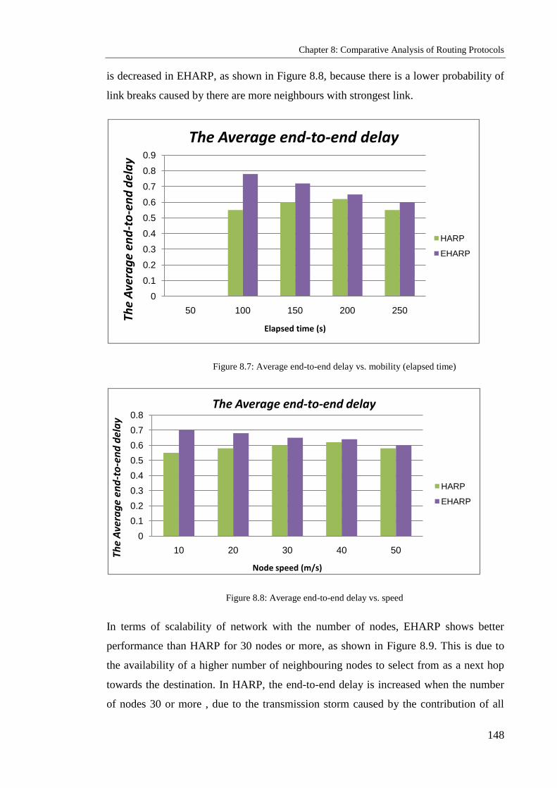
Chapter 8: Comparative Analysis of Routing Protocols
148
is decreased in EHARP, as shown in Figure 8.8, because there is a lower probability of
link breaks caused by there are more neighbours with strongest link.
Figure 8.7: Average end-to-end delay vs. mobility (elapsed time)
Figure 8.8: Average end-to-end delay vs. speed
In terms of scalability of network with the number of nodes, EHARP shows better
performance than HARP for 30 nodes or more, as shown in Figure 8.9. This is due to
the availability of a higher number of neighbouring nodes to select from as a next hop
towards the destination. In HARP, the end-to-end delay is increased when the number
of nodes 30 or more , due to the transmission storm caused by the contribution of all
0
0.1
0.2
0.3
0.4
0.5
0.6
0.7
0.8
0.9
50 100 150 200 250
The
Ave
rag
e en
d-t
o-e
nd
del
ay
Elapsed time (s)
The Average end-to-end delay
HARP
EHARP
0
0.1
0.2
0.3
0.4
0.5
0.6
0.7
0.8
10 20 30 40 50The
Ave
rag
e en
d-t
o-e
nd
del
ay
Node speed (m/s)
The Average end-to-end delay
HARP
EHARP

Chapter 8: Comparative Analysis of Routing Protocols
149
nodes in the network in flooding the route request packets, which in turn increase the
delay in finding the route
Figure 8.9: Average end-to-end delay vs. network size
8.3 Comparative Analysis of Results for SEHARP and
EHARP
The metrics mentioned above are important determinants of network performance. We
have used them to compare the network performance of our scheme with that achieved
using the original protocol. The results of this study show that our scheme enhances the
security of the routing protocol without causing substantial degradation in network
performance.
8.3.1 Efficiency of Data Packet delivery
Figures 8.10, 8.11 and 8.12 compare the efficiency of the proposed SEHARP scheme
with EHARP by plotting ERDP against mobility with elapsed times, node speeds and
network sizes. In general, it can be seen that the ERDP is lower in SEHARP than in
0
0.1
0.2
0.3
0.4
0.5
0.6
0.7
0.8
0.9
10 20 30 40 50
The
Ave
rag
e en
d-t
o-e
nd
del
ay
Network size (node)
The Average end-to-end delay
HARP
EHARP

Chapter 8: Comparative Analysis of Routing Protocols
150
EHARP and better than in HARP in terms of elapsed time, speed and number of nodes.
Because the throughput of the network decreases after incorporating SEHARP, the
ERDP is low in many cases. When elapsed times increases, a number of data packets
waiting for route discovery are dropped, hence fewer data packets reach the destination,
but the decrease in throughput is only about 3%. As the number of routing packets
increases, this can again be attributed to the authentication overhead.
Figure 8.10: Efficiency of data packet delivery vs. mobility (pause time)
Figure 8.11: Efficiency of data packet delivery vs. speed
0
0.02
0.04
0.06
0.08
0.1
0.12
0.14
0.16
0.18
0.2
50 100 150 200 250The
eff
icie
ncy
of
dat
a p
acke
t d
eliv
ery
Elapsed time (s)
The efficiency of data packet delivery
SEHARP
EHARP
0
0.02
0.04
0.06
0.08
0.1
0.12
0.14
0.16
0.18
10 20 30 40 50The
effi
cien
cy o
f d
ata
pa
cket
del
iver
y
Node speed(m/s)
The efficiency of data packet delivery
SEHARP
EHARP

Chapter 8: Comparative Analysis of Routing Protocols
151
Analysing the scalability of the network with the number of mobile nodes, Figure 8.12
plots the ERDP against the number of nodes. As increases nodes, the ERDP for
SEHARP decreases. This indicates that a larger ad hoc wireless network has a higher
number of nodes which will contribute to the formation of a route, increasing the
probability of link breaks and thus requiring more overhead to re-establish broken
routes. The ERDP of EHARP is better than that of SEHARP because when the network
size is increased, the SEHARP overhead also increases, which affects the ERDP.
Figure 8.12: Efficiency of data packet delivery vs. network size
8.3.2 Route Discovery Packets (overhead)
In Figures 8.13, 8.14 and 8.15 show that in general, under SEHARP the number of
packets needed for routing increases more than EHARP because the secure path for
exchanging the authentication of route request packets involves the exchange of
additional packets. We have reduced the packet overhead by restricting authentication
to route replies alone. The increase in routing load is higher at greater mobility and
reduced at lower mobility, because at higher mobility, routes need to be found more
frequently; therefore more authentications are needed.
Figure 8.13 plots the number of route discovery packets throughout the simulation
period with information captured at 50 sec and interval. It can be seen that the number
0
0.02
0.04
0.06
0.08
0.1
0.12
0.14
0.16
0.18
10 20 30 40 50The
effi
cien
cy o
f d
ata
pa
cket
del
iver
y
Network size (node)
The efficiency of data packet delivery
SEHARP
EHARP

Chapter 8: Comparative Analysis of Routing Protocols
152
of route discovery packets needed to find a path is much higher in SEHARP than in
EHARP. This is because SEHARP need secure path packet.
Figure 8.13: Route discovery vs. mobility (elapsed time)
The impact of node speeds on the number of route discovery packets for our scheme is
shown in Figure 8.14, which plots route discovery against speed of node movement. As
speed increases, the number of route discovery packets generated by SEHARP and
HARP increases due to the higher speed of nodes in the network requires more packets
to cope with network topology changes and route break recovery. Significantly more
route discovery packets are generated in SEHARP than in EHARP due to with increase
speed of nodes the routes need more authentication packet.
0
10000
20000
30000
40000
50000
60000
50 100 150 200 250
The
Ro
ute
dis
cove
ry p
acke
ts
Elapsed time (s)
The Route discovery packets (Overhead)
SEHARP
EHARP
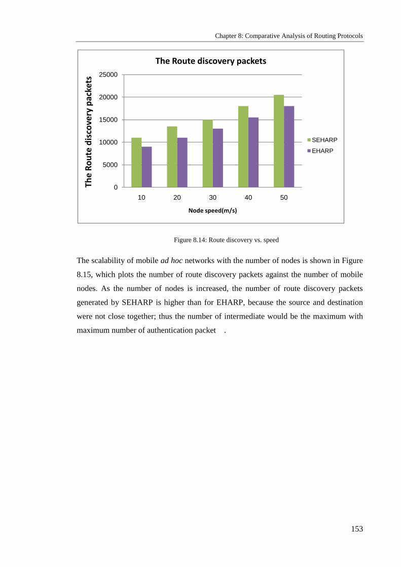
Chapter 8: Comparative Analysis of Routing Protocols
153
Figure 8.14: Route discovery vs. speed
The scalability of mobile ad hoc networks with the number of nodes is shown in Figure
8.15, which plots the number of route discovery packets against the number of mobile
nodes. As the number of nodes is increased, the number of route discovery packets
generated by SEHARP is higher than for EHARP, because the source and destination
were not close together; thus the number of intermediate would be the maximum with
maximum number of authentication packet .
0
5000
10000
15000
20000
25000
10 20 30 40 50
The
Ro
ute
dis
cove
ry p
acke
ts
Node speed(m/s)
The Route discovery packets
SEHARP
EHARP

Chapter 8: Comparative Analysis of Routing Protocols
154
Figure 8.15: Route discovery vs. network size
8.3.3 Average end-to-end Delay
In Figures 8.16, 8.17 and 8.18 show that in general a secure path which uses
authentication causes more overhead in the SEHARP scheme. Authentication increases
the route discovery latency and causes more data packets to queue up. As a result, we
see that the average end-to-end delay under SEHARP is greater than for EHARP. It
should be noted that this increase in delay is a worst-case scenario for SEHARP and
that it occurs when there are no malicious nodes. The delay under EHARP can be much
higher in the presence of attacks. The values shown are the average delays for all data
packets. The only ones which increase are for data packets waiting for route discovery,
whereas delays for all other data packets are unaffected. Therefore, the increase in the
end-to-end delay is fairly low.
A comparison of SEHARP with EHARP in terms of the average end-to-end delay of
transferred data packets against mobility for elapsed times, node speeds and numbers of
mobile nodes is made in Figures 8.16, 8.17 and 8.18. It can be seen that under SEHARP
the average delay is greater than for EHARP. This is because SEHARP need secure
path to forwarding the route request packets to a few selected nodes which have the
0
5000
10000
15000
20000
25000
30000
35000
40000
10 20 30 40 50
The
Ro
ute
dis
cove
ry p
acke
ts
Network size (node)
The Route discovery packets
SEHARP
EHARP

Chapter 8: Comparative Analysis of Routing Protocols
155
strongest stability links. Therefore, additional delays will occur during the establishment
of the path to the destination. When the speed of mobile nodes is increased, the average
end-to-end delay in SEHARP greater than EHARP, as shown in Figure 8.18, because
there is a higher probability of link breaks due to it needs more authentications.
Figure 8.16: Average end-to-end delay vs. mobility (pause time)
In terms of the scalability of the network by increasing the number of nodes, EHARP
performs better than SEHARP, because it selects the only nodes have the secure path
with strongest link as the next hop towards the destination.
0
0.1
0.2
0.3
0.4
0.5
0.6
0.7
0.8
0.9
50 100 150 200 250The
Ave
rag
e en
d-t
o-e
nd
del
ay
Elapsed time (s)
The Average end-to-end delay
SEHARP
EHARP
decrese

Chapter 8: Comparative Analysis of Routing Protocols
156
Figure 8.17: Average end-to-end delay vs. speed
Figure 8.18: Average end-to-end delay vs. network size
0
0.1
0.2
0.3
0.4
0.5
0.6
0.7
0.8
0.9
1
10 20 30 40 50
The
Ave
rag
e en
d-t
o-e
nd
del
ay
Node speed (m/s)
The Average end-to-end delay
SEHARP
EHARP
0
0.1
0.2
0.3
0.4
0.5
0.6
0.7
0.8
10 20 30 40 50
The
Ave
rag
e en
d-t
o-e
nd
del
ay
Network size (node)
The Average end-to-end delay
HARP
EHARP

Chapter 8: Comparative Analysis of Routing Protocols
157
8.4 Summary
This chapter has presented a comparative analysis of the proposed routing algorithms,
EHARP and SEHARP, against the HARP routing protocols, which were evaluated
using the most popular network simulator among ad hoc researchers, NS-2. The results
show that EHARP clearly offers a significant reduction in the cost of route discovery
packets (overhead) in comparison with HARP and that this scheme is less affected by
mobility, speed and number of nodes than HARP in terms of the efficiency of data
packet delivery
It was noticed, however, that the increased average end-to-end delay under EHARP put
it at a disadvantage compared to HARP. In spite of this limitation, in many applications,
finding the path that lasts longest with reduced overhead and collisions and with an
acceptable level of delay is crucially important; furthermore, this acceptable delay is
application dependant.
In terms of route discovery, at elapsed times, EHARP was found to perform better than
HARP, while at longer elapsed time, EHARP performed better than HARP. EHARP
was found to perform better in route discovery against speed than either HARP.
In analyzing the ERDP, in terms of pause time, EHARP was found to perform better
than HARP, as it did in route discovery with respect to the number of nodes.
The second set of quantitative analyses compared the performance of the proposed
security protocol, SEHARP, with EHARP, using the same evaluation metrics. The
algorithm performed well in scenarios where mobility, speed and network size were
varied. The simulation results show that SEHARP functions very similarly to the
EHARP protocol and better than HARP.

Chapter 9: Conclusions and Future Work
158
Chapter 9
Conclusions and Future Work
Objectives: to present
Summary
Contributions
Future work
9.1 Summary
Rapid advances in the technology of wireless communication systems and small, lightweight,
portable devices have had significant effects in the field of mobile ad hoc wireless networks.
Designing communication protocols and applications for such networks is very challenging due
to the absence of fixed infrastructure, the inevitable mobility and constrained bandwidth. It is
crucial in ad hoc wireless networks to deliver data packets effectively, minimise connection
breakdown and control packet overhead, while ensuring that a route remains connected for the
longest possible period. The mobility of the nodes of these networks presents the most difficult
challenge to routing protocol designers, because it causes frequent topology changes and route
invalidation, which increase the signaling overhead required to establish routes, thus affecting
the performance of the routing protocols. Therefore, these protocols must construct and
maintain multichip routes in dynamic networks effectively and efficiently. However, this need
brings with it new security vulnerabilities that are specific to the ad hoc environment. Limited
battery life and computational power and the lack of fixed infrastructure make the design and
implementation of a security scheme very challenging.
While the routing protocols proposed for mobile ad hoc wireless networks seem to meet rather
well the basic requirements, such as dynamically changing network topologies, security issues
have generally been ignored. These protocols must be secure from the viewpoint of
authentication, integrity and privacy, requirements which can be at least partially met by using
strong secure path and encryption mechanisms, digital signatures and hashing. Moreover, the
means of protection can be optimized for every protocol based on the approach taken to routing.
Some ad hoc wireless network routing protocols have been developed in response to security

Chapter 9: Conclusions and Future Work
159
needs, but such an approach is not totally adequate, due to the problems of replay etc, as
discussed in the earlier chapters.
Secure routing is a central aspect of security in ad hoc wireless networks. Solutions to the
problem of public secure routing protocols have been presented in chapter 2and 3. Some of
these, such as the SAODV and SEAD schemes, rely on adapting the hash function in order to
provide secure, available key management services. Most of these solutions are based on
enhancements to existing routing protocol. They are quite elegant and potentially offer a good
measure of security and availability, but they still have many drawbacks and may not be
applicable to most commercial WMANET environments for various reasons, such as the high
maintenance overhead.
Solutions to routing protocol security problems in general and to key management and secure
path provision in particular should be built upon a strong foundation. This means constructing a
specialised reference paradigm for routing protocol security that helps in modelling it,
addressing security challenges, defining security attacks and security requirements and
describing principles and plans to achieve all the objectives of these security requirements, then
proposing security mechanisms to enforce the implementation of these objectives. This
methodology was followed in chapters 4-8.
Chapter 4 establishes the EHARP model for ad hoc networks. It starts by defining the system
model and listing the assumptions adopted in developing the new algorithm. It then describes
the general network model, the mobility model, the traffic model and the general system model,
including the format of all types of messages used in these algorithms. Chapter 5 presents the
design and development of the proposed EHARP protocol, including the evaluation and
simulation results based on the NS-2 network simulator package.
Chapter 6 demonstrates the proposed SEHARP secure protocol and proposes a novel security
mechanism for secure routing in ad hoc wireless networks. It also presents the validation and
simulation results based on the NS-2 package.
Chapter 7 proposes a novel approach to security of access in hostile environments based on the
history of the network nodes. It also proposes an access activity diagram and code which
explain the steps taken by a node while handling requests to access a secure environment. This
is a comprehensive solution, providing a high level of security for ad hoc environments that is
available, scalable, flexible, reliable and efficient. The approach is evaluated by means of a
military case study.

Chapter 9: Conclusions and Future Work
160
Chapter 8 presents a comparative analysis of EHARP by comparing its performance with that of
the HARP and AODV routing protocols. There is also a comparative analysis of EHARP and
SEHARP; the same evaluation metrics used for evaluating these two protocols are used to
compare them.
9.2 Contributions
The main contributions of this work to the existing literature on the subject are the definition of
the architecture for the EHARP routing protocol and the new secure routing protocol
(SEHARP) for ad hoc wireless networks. Both EHARP and SEHARP are unique in the respect
that no comparable proposals have been made. In addition, the secure environment approach is
applied to the problem of regulating access to a hostile environment in an ad hoc wireless
network. The ad hoc environment assumption and the way it is used in defining these protocols
is of itself a novelty. The contributions made by this study are detailed in the following sections.
9.2.1 Enhanced Heading-direction Angle Routing Protocol
The first contribution is the proposal of a new routing protocol, EHARP, where each node in the
network is able to classify its neighbouring nodes according to their heading directions into four
different zone-direction groups. The zone direction is reduced until the node can select the
strongest and most stable link, so increasing availability in the network.
Each node in the network has a counter for the stability of the links to its neighbouring nodes.
This SL counter indicates which nodes are active in the network, thus improving the
performance of the network and increasing the likelihood of selecting the best or optimal path.
The SL counter has an initial value of zero, which is increased by 1 after every successful
sending or receiving and reduced by 1 after every failure in sending or receiving. The strongest
SL is based on the greatest value registered by the counter.
This protocol is based on the time and the sending of an acknowledgement message in order to
guarantee the selection of the path and link stability. The source node must resend the route
request whenever a certain time elapses before receiving the error message, in order to make use
of the full lifetime of the links. Each node will send an acknowledgement message after
receiving an RREQ and forwarding it, so the acknowledgement message should provide
information on which nodes have problems or have been unable to forward the RREQ.
9.2.2 Secure Enhanced Heading-direction Angle Routing Protocol
The second contribution is to propose a novel secure routing protocol for ad hoc wireless
networks, SEHARP, designed to improve the security level, based on key management and a
Chapter 9: Conclusions and Future Work
161
secure node-to-node path, which protects data and satisfies our security requirements: the
detection of malicious nodes, authentication, authorisation, confidentiality, availability, data
integrity and a guarantee of secure correct route discovery.
SEHARP works as a group and has three stages:
1) Distribution of keys and certificate stage
Our scheme adopts the network backbone node system because of its superiority in distributing
keys and achieving integrity and non-repudiation. The system uses private and public keys. The
former are used to sign certificates and the public key of all the nodes, while the latter is used to
renew certificates that are issued by another NBBN.
2) Secure path stage
Our approach is to use a public-key algorithm to establish secure paths between nodes. The
secure path stage requires all nodes to have an SP with other nodes before sending any route
request packet. Any node receiving an RREQ from the source node or another node without an
SP should discard the request.
3) Secure routing protocol stage
At this stage our approach uses a hybrid of security mechanisms to introduce SEHARP so that it
satisfies the main security requirement and guarantees the discovery of a correct and secure
route. The security mechanisms that the protocol uses are the hash function, digital signature
and time synchronisation.
The performance of these two protocols was tested in simulation and their communication costs
were measured using the NS-2 simulator, which was suitable for the present purpose. The
evaluation metrics used in this study were success ratio, delay, average number of retries and
overhead.
9.2.3 Secure Ad Hoc Environments
The third contribution of the study is to propose a new approach to ensuring security of access
in hostile environments based on the history of the nodes of a network. It also proposes an
access activity diagram and code which explain the steps taken by a node while handling
requests to access a secure environment.
In an SE, some of the ad hoc nodes are involved in other infrastructure-based wireless networks
such as WLANs and cellular systems; therefore, each of the ad hoc nodes will belong to an

Chapter 9: Conclusions and Future Work
162
operation service provider. Other non-managed ad hoc wireless network nodes, which are not
involved in any other wireless networks, will be managed by the OSP, in order for those
undefined nodes or networks to be able to access our SE.
Security depends on access to the history of each unit, which is used to calculate the
cooperative values of each node in the environment. The calculated cooperative values are then
used by the relationship estimator to determine the status of the nodes. Every node should be
capable of making its own security decisions based on cooperation with other peer nodes. The
solution is a combination of the history of the nodes and operation certificates. Each node in an
SE is uniquely identified by its public key. This solution protects against various vulnerability
issues affecting wireless links such as active and passive attacks. It is scalable and does not
depend on other nodes. The dynamic nature of networks and their membership does not affect
the solution, since each node makes access decisions on its own and the use of cooperative
algorithms is avoided.
This approach has been evaluated by a military case study, where the performance of the access
to hostile environments was evaluated using a formal description. In addition, a military case
study in an unknown and unprotected environment is provided to show a real example of
behaviour detection.
9.2.4 Comparative Analysis
The EHARP and SEHARP protocols were both evaluated using the NS-2 network simulator,
testing the two proposed protocols in real network environments and measuring their
communication costs using other evaluation metrics such as the data packet delivery ratio, the
efficiency of data packet delivery, the average end-to-end-delay of data packets, the broken link
rate and overheads.
A quantitative analysis was then performed, comparing the performance of the EHARP and
HARP protocols and that of SEHARP with EHARP. The same evaluation metrics used for
evaluating the EHARP and SEHARP protocols were used for the comparisons. Both protocols
performed well in different mobility, speed and network size scenarios. The simulation results
show that exploiting the link stability of nodes in EHARP would allow routes to remain
connected longer and overcome the effects of the flooding technique and overhead in the
network. This is achieved by selective forwarding and elongating the lifetime of routes. There
was also a reduction in the effect of flooding in terms of the number of routing discovery
packets needed to deliver data packets with different mobility, speed of nodes and network size.
Results also show that the ratio of the number of data packets delivered to their destinations to

Chapter 9: Conclusions and Future Work
163
the number of all packets generated in the networks is higher in EHARP than in the
conventional AODV protocol, which is a result of choosing the longest path to the destination.
The second set of quantitative analyses compared the performance of the proposed security
protocol, SEHARP, with AODV and EHARP, using the same evaluation metrics. The protocol
performed well in scenarios where mobility, speed and network size were varied. The delay and
average number of dropped packets incurred by EHARP was lower than for SEHARP. In
contrast, AODV was found to cause more overhead than SEHARP.
The simulation results show that SEHARP functions very similarly to the EHARP protocol and
better than AODV.
9.3 Future Work
The following list identifies areas of research which are worth pursuing.
EHARP: In order to improve the performance of the enhanced routing protocol based
on link stability and time, as presented in chapter 5, there should be a detailed
investigation of the choice of the number of zones into which a node‘s neighbours are
grouped according to the stability of links between nodes in the network. A further step
to enhance its performance would use outdoor locating devices (e.g., GPS) it is both
technically and economically feasible for a mobile device to know its physical
location.
SEHARP: The secure routing protocol based on secure paths presented in chapter 6
guarantees a comprehensive security solution for ad hoc wireless network routing
protocols. This thesis has presented the implementation of the protocol in three stages.
There are therefore still other possible mechanisms by which to achieve the objectives
of all security requirements, by combining these stages into one. An interesting
observation is that the security architecture of the routing protocol has provided us with
a clear line of defence.
Security mechanism enhancements: Security of access based on node history and
operation certificates, as presented in chapter 7, guarantees a security solution for
access to ad hoc wireless networks in hostile environments. Some enhancements that

Chapter 9: Conclusions and Future Work
164
could be made in the future to the security of access in hostile environments and its
evaluation would be to provide a design for a routing protocol based on node history
and supported by evaluation using NS-3, which has all the event components necessary
to implement the history-of-nodes algorithm. An alternative would be to run an Ana
Tempura simulation and then to conduct a comparative analysis of the NS-3 and Ana
Tempura results.
Ad hoc wireless network challenges: There are interesting challenges facing ad hoc
wireless networks, in addition to security, which are worth investigating in future work.
These include:
The design of multicast routing protocols
The development of MAC layer protocols
Approaches to efficient load balancing
Provision of end-to-end quality of service
The design of power-efficient protocols
Cross-layer design for wireless networks
The development of a multipath routing approach
Pricing schemes in ad hoc networks.

References
165
10. References
[1] C.-K. Toh, , “Ad Hoc Mobile Wireless Networks: Protocols and Systems”, Prentice-
Hall, New Jersey, pp: 34-37, 2002
[2] C. Siva Ram Murthy and B.S. Manjo, “Ad Hoc Wireless Networks: Architectures and
Protocols”, Prentice Hall communications engineering and emerging technologies series
Upper Saddle River, 2004.
[3] Singh S., Raghavendra C.S., “Power efficient MAC protocol for multihop radio
networks”, Personal, Indoor and Mobile Radio Communications, 1998. The Ninth IEEE
International Symposium on, Volume: 1 , 8-11 Sept. 1998, pp:153 – 157.
[4] Perkins C.E., Royer E.M., “Ad-hoc on-demand distance vector routing Mobile
Computing Systems and Applications”, Proceedings. WMCSA'99. Second IEEE Workshop
on, 25-26 Feb. 1999, pp: 90 – 100.
[5] C. Chiang, Gerla M., Zhang L., “Adaptive shared tree multicast in mobile wireless
networks”, Global Telecommunications Conference, GLOBECOM 98. The Bridge to
Global Integration. IEEE , Volume: 3 , 8-12 Nov. 1998, pp:1817 – 1822.
[6] Toh, C.-K., ―Maximum battery life routing to support ubiquitous mobile computing in
wireless ad hoc networks‖, Communications Magazine, IEEE, Volume: 39 , Issue: 6, June
2001, pp:138 – 147.
[7] Holland G., Vaidya N., “Impact of routing and link layers on TCP performance in
mobile ad hoc networks”, Wireless Communications and Networking Conference, WCNC.
1999 IEEE , 21-24 Sept. 1999, pp:1323 – 1327.
[8] B. Dahill, B. Neil Levine, E. Royer and C. Shields, “A Secure Routing Protocol for Ad
Hoc Networks“, Technical report UM-CS-2001-037, University of Massachusetts,
Amherst, August, 2001.
[9] Y. Hu, A. Perrig, and D.B. Jonson, “Ariadne: A Secure On-Demand Routing for Ad hoc
Networks”, Proceedings of ACM MOBICOM 2002, pp:12-23, September 2002.

References
166
[10] Jameela Al-Jaroodi, “Security Issues In Wireless Mobile Ad Hoc Networks (MANET)”,
Technical Report TR02-10-07, University of Nebraska-Lincoln, 2002.
[11] William Stallings, “Cryptography and Network Security: Principles And Practices”,
3rd Edition, Prentice Hall 2003, ISBN: 0-13-091429-0.
[12] Klas Fokine, “Key Management in Ad Hoc Networks”, Master Thesis, Linkping
University, 2002. http://www.liu.se/.
[13] Bruce Schneier, “Applied Cryptography”, 2nd Edition, John Wiley & Sons, 1996,
ISBN 0-471-11709-9.
[14] National Institute of Standards and Technology (NIST), available at
http://www.nist.gov/, last visit 8 May 2007.
[15] Whitfield Diffie and Martin Hellman, "New Directions in Cryptography", IEEE
Transactions on Information Theory, vol. IT-22, pp: 29-40, November 1976.
[16] ITU-T Recommendation X.509, ―Public-key and attribute certificate frameworks‖,
August 2005.
[17] N. Asokan and P. Ginzboorg, “Key-Agreement in Ad Hoc Networks”, Computer
Communications, vol.23, no. 17, pp: 1627-1637, 2000.
[18] M. Bechler, H.-J. Hof, D.Kraft, F. Pahlke, L. Wolf, ‖A cluster-based security
architecture for ad hoc networks‖, INFOCOM 2004. Twenty-third Annual Joint Conference
of the IEEE Computer and Communications Societies, Volume 4, 7-11 March 2004
Page(s):2393 - 2403 vol.4
[19] Y. Frankel, P. Gemmell, P. D. MacKenzie and M. Yung, “Proactive RSA“, In
Proceedings of CRYPTO 1997, Springer Verlag LNCS, pp: 440–454, 1997.
[20] S. Yi, P. Naldurg and R. Kravets, “Security-Aware Ad hoc Routing for Wireless
Networks”, Proceedings of ACM MOBIHOC 2001, pp. 299-302, October 2001.

References
167
[21] K. Sanzgiri, B. Dahill, B. Neil Levine, C. Shields and E. Royer, “A Secure Routing
Protocol for Ad Hoc Networks”, Proceedings of IEEE ICNP 2002, pp: 78-87, November
2002.
[22] M. G. Zapata and N. Asokan, “Securing Ad hoc Routing Protocols”, Proceedings of
the 2002 ACM Workshop on Wireless Security (WiSe 2002). S. 1- 10. September 2002.
[23] Y.-C. Hu, D. B. Johnson and A. Perrig, “SEAD: Secure Efficient Distance Vector
Routing for Mobile Wireless Ad Hoc Networks“, Proceedings of the Fourth IEEE
Workshop on Mobile Computing Systems and Applications (WMCSA‘02), Callicoon, New
York, USA, June 20-21, 2002.
[24] E. M. Royer, ―A Review of Current Routing Protocols for Ad Hoc Mobile Wireless
Networks‖, IEEE Personal Communication April 1999.
[25] C. Siva Ram Murthy and B.S. Manoj, ―Ad Hoc Wireless Networks: Architectures‖,
book, ISBN 0-13-147046-X, first printing, 2004.
[26] M. Abolhasan, T. Wysocki, E. Dutkiewicz, ―A review of routing protocols for mobile
ad hoc networks‖, Ad Hoc Networks journal, Elsevier Science, Vol. 2, 2004.
[27] C.E. Perkins, T.J. Watson, ―Highly dynamic destination sequenced distance vector
routing (DSDV) for mobile computers‖, in: ACM SIGCOMM‘94 Conference on
Communications Architectures, London, UK, 1994.
[28] S. Murthy and J.J. Garcia-Luna-Aceves, ―An Efficient Routing Protocol for Wireless
Networks‖, ACM/Baltzer Mobile Networks and Applications, special issue on Routing in
Mobile Communications Networks, vol. 1, no. 2, October 1996.
[29] S. Murthy J.J. Garcia-Luna-Aceves, ―A routing protocol for packet radio networks‖,
in: Proceedings of the First Annual ACM International Conference on Mobile Computing
and Networking, Berkeley, CA, 1995.
[30] T. Clausen, P. Jacquet, A. Laouiti, P. Muhlethaler, a. Qayyum et L. Viennot,
―Optimized Link State Routing Protocol‖, IEEE INMIC Pakistan 2001.

References
168
[31] G. Pei, M. Gerla, T.-W. Chen, ―Fisheye State Routing in Mobile Ad Hoc Networks‖
ICDCS Workshop on Wireless Networks and Mobile Computing, 2000 .
[32] G. Pei, M. Gerla, T.-W. Chen, ―Fisheye State Routing: A Routing Scheme for Ad Hoc
Wireless Networks", Proceedings of the IEEE International Conference on Communications
(ICC), New Orleans, LA, June 2000.
[33] J.J. Garcia-Luna-Aceves and M. Spohn, ―Source-Tree Routing in Wireless Networks",
Proceedings of the IEEE International Conference on Network Protocols (ICNP), Toronto,
Canada, October, 1999.
[34] T.-W. Chen and M. Gerla, ―Global State Routing: A New Routing Scheme for Ad-hoc
Wireless Networks," Proceedings of the IEEE International Conference on Communications
(ICC), Atlanta, GA, June 1998.
[35] R.E. Bellman, ―Dynamic Programming‖, Princeton University Press, Princeton, NJ,
1957.
[36] L.R. Ford and D.R. Fulkerson, ―Flows in Networks‖, Princeton University Press,
Princeton, NJ, 1962.
[37] C.-C. Chiang, H. K. Wu, W. Liu, and M. Gerla, ―Routing in clustered multihop mobile
wireless networks with fading channel‖, in: Proceedings of IEEE SICON, April 1997.
[38] D. B. Johnson and D. A. Maltz, ―Dynamic source routing in ad-hoc wireless
networks,‖ in Mobile Comput., T. Imielinski and H. Korth, Eds: Kluwer, 1996.
[39] V.D. Park, M.S. Corson, ―A highly adaptive distributed routing algorithm for mobile
wireless networks,‖ Proceedings of the IEEE Conference on Computer Communications
(INFOCOM), Kobe, Japan, April 1997, pp.1405-1413.
[40] C. E. Perkins, E. M. Belding-Royer, S. R. Das, ―Ad hoc On-Demand Distance Vector
(AODV) Routing‖, (Internet-draft), in: Mobile Ad-hoc Network (MANET) Working
Group, IETF, 17 February 2003.
[41] V. PARK, S. CORSON, ―Temporally-Ordered Routing Algorithm (Tora) Version 1‖,
Internet Draft, draft-ietf-manet-tora-spec- 03.txt, work in progress, June 2001.

References
169
[42] C-K. Toh, ―Associativity-Based Routing for Ad-Hoc Networks‖, Wireless Personal
Communications Journal, Special Issue on Ad-Hoc Networks, Vol. 17, No. 8, August
1999.
[43] C. Toh, ―A novel distributed routing protocol to support ad-hoc mobile computing‖,
IEEE 15th Annual International Phoenix Conf., 1996.
[44] R. Dube, C.D. Rais, K-Y.Wang and S.K. Tripathi, ―Signal Stability-Based Adaptive
Routing (SSA) for Ad-Hoc Mobile Networks‖, IEEE Personal Communications journal,
February 1997.
[45] X. Zou, B. Ramamurthy, ―Routing Techniques in Wireless Ad Hoc Networks -
Classification and Comparison‖, The Sixth World Multiconference on Systemics,
Cybernetics, and Informatics, SCI 2002, Volume IV, Orlando, Florida, USA, 15-18. July
2002
[46] Z. J. Haas, M. R. Pearlman, and P. Samar, ―The Zone Routing Protocol (ZRP) for Ad
Hoc Networks‖, draft-ietf-manet-zone-zrp-04.txt, July, 2002
[47] R. Sivakumar, P. Sinha, and V. Bharghavan, ―CEDAR: a Core-Extraction Distributed
Ad hocRouting algorithm‖, IEEE Journal On Selected Areas In Communication, Vol 17,
No 8, August 1999.
[48] M. Alchaita, M. Al-Akaidi, J. Ivins, ―New On-demand Routing Approaches for Ad
Hoc Networks‖, PGNet 2005, sixth annual postgraduate symposium, the convergence of
telecommunications, networking and broadcasting, 27th-28th June 2005.
[49] Prashant Dewan and Partha Dasgupta, “Trusting Routers and Relays in Ad hoc
Networks”, Proceedings of the 2003 International Conference on Parallel Processing
Workshops (ICPPW‘03), 2003.
[50] Y. Hu, A. Perrig, and D.B. Jonson, “Ariadne: A Secure On-Demand Routing for Ad
hoc Networks”, Proceedings of ACM MOBICOM 2002, pp. 12-23, September 2002.
[51] Mohamed G. Gouda and Eunjin Jung, “Certificate Dispersal in Ad-Hoc Networks“,
IEEE Proceedings of the 24th
International Conference on Distributed Computing Systems
(ICDCS‘04), 2004.

References
170
[52] S. Yi, P. Naldurg and R. Kravets, “Security-Aware Ad hoc Routing for Wireless
Networks”, Proceedings of ACM MOBIHOC 2001, pp. 299-302, October 2001.
[53] William Stallings, “Cryptography and Network Security: Principles And Practices”,
3rd Edition, Prentice Hall 2003, ISBN: 0-13-091429-0.
[54] Klas Fokine,“Key Management in Ad Hoc Networks”, Master Thesis, Linkping
University, 2002. http://www.liu.se/.
[55] Krishna Paul, Romit Roy Choudhuri, S. Bandyopadhyay, ―Survivability Analysis of Ah
Hoc Network Architecture‖, Proceedings of the IFIP-TC6/European Commission International
Workshop on Mobile and Wireless Communication, Vol. 1818, pp. 31 – 46, 2000.
[56] Praphul Chandra, ―Bulletproof Wireless Security GSM, UMTS, 802.11 and Ad Hoc
Security‖ Elsevier, 2005, ISBN: 0-7506-7746-5.
[57] Amitabh Mishra and Ketan M. NadKarni, ―Security in Wireless Ad Hoc Networks‖,
The Hand Book of Ad hoc Networks, CRC Press, FL, USA, 2003, pp. 479-490, ISBN: 0-8493-
1332-5.
[58] Xing Fei; Wang Wenye, ―Understanding Dynamic Denial of Service Attacks in
Mobile Ad Hoc Networks‖, MILCOM 2006, Oct. 2006, pp. 1 – 7.
[59] Tzeng Wen-Guey, ―A secure fault-tolerant conference-key agreement protocol
Computers‖, IEEE Transactions on Volume 51, Issue 4, April 2002,pp. 373 – 379.
[60] William Stallings, “Cryptography and Network Security: Principles And Practices”,
3rd Edition, Prentice Hall 2003, ISBN: 0-13-091429-0.
[61] Bruce Schneier, “Applied Cryptography”, 2nd Edition, John Wiley & Sons, 1996,
ISBN 0-471-11709-9.
[62] National Institute of Standards and Technology (NIST), available at
http://www.nist.gov/ , last visit 26 October 2009.
[63] Whitfield Diffie and Martin Hellman, "New Directions in Cryptography", IEEE
Transactions on Information Theory, vol. IT-22, pp. 29 – 40, November 1976.

References
171
[64] Wikipedia.org, "Man in the middle attack", available at:
http://en.wikipedia.org/wiki/Man_in_the_middle , last visit 26 October 2008.
[65] ITU-T Recommendation X.509, ―Public-key and attribute certificate frameworks‖,
August 2005.
[66] PGPi.org, Documentation, "How PGP works", available at
http://www.pgpi.org/doc/pgpintro/#p12 , last visit 2nd
December 2008.
[67] Philip R. Zimmermann, “The official PGP user's guide”, Cambridge, Mass; London:
MIT Press. xviii, 127p, 1995.
[68] Simson Garfinkel, “PGP: pretty good privacy”, Minor corr. March 1995 ed., Beijing:
O'Reilly & Associates. xxxiii, 393 p, 1995.
[69] Bo Sun, Kui Wu, Yang Xiao, and Ruhai Wang, ―Integration of Mobility and Intrusion
detection for wireless ad hoc networks‖, International Journal of Communication Systems,
pp. 695 – 721, 2007.
[70] Y. Zhang, W. Lee, and Y. Huang, ―Intrusion Detection Techniques for Mobile
Wireless Networks‖, ACM Wireless Networks Journal (ACM WINET), Vol. 9, No. 5,
September 2003.
[71] Oleg Kachirski, and Ratan Guha, ―Intrusion Detection Using Mobile Agents in
Wireless Ad Hoc Networks‖, Knowledge Media Networking, 2002 IEEE Proceedings, pp.
153 – 157, 10 – 12 July 2002.
[72] Yu-Fang Chung, Tzer-Shyong Chen, Chia-Hui Liu, Tzu-Chi Wang, ―Efficient Hierarchical
Key Management Scheme for Access Control in the Mobile Agent‖, Advanced Information
Networking and Applications – Workshops, 2008. AINAW 2008. 22nd
International conference, pp.
650 – 655, 25 – 28 March 2008.
[73] S. Bellemo, and J. D. Smith, ―Attributes of Effective Configuration Management for Systems of
Systems‖, System Conference 2008 2nd
Annual IEEE, pp. 1 – 8, April 2008.

References
172
[74] Jim Ironside, LtdCol R. J. Spencer, ―Network Centric Warfare Operation in an
Expeditionary Context‖, Military information & Communications, symposium of South
Africa (MICSSA), July 26, 2007.
[75] A. Shamir, “How to Share a Secret”, Communications of ACM, 1979.
[76] Bing Wu, Jie Wu, Eduardo B. Fernandez and Spyros Magliveras, “Secure and
Efficient Key management in Mobile Ad hoc Network”, Proceedings of the 19th IEEE
International Prallel and Disributed Processing Symposium (IPDPS‘05), 2005.
[77] John R. Douceur, “The Sybil Attack”, Electronic Proceedings for the 1st
International
Workshop on Peer-to-Peer Systems (IPTPS '02), 2002.
[78] Azzedine Boukerche, Yonglin Ren, ―A security management scheme using a novel
computational reputation model for wireless and mobile ad hoc networks‖, PE-WASUN
'08: Proceedings of the 5th ACM symposium on Performance evaluation of wireless ad hoc, sensor,
and ubiquitous networks, October 2008.
[79] Panlog Yang, Shaoren Zheng, ―Security Management in Hierarchical Ad Hoc
Network‖, Info-tech and Info-net, 2001. Proceedings. ICII 2001 - Beijing. 2001 International
Conferences, Vol. 2, pp. 642 – 649, 29 Oct.-1 Nov. 2001.
[80] H. Zheng, S. Wang, R. A. Nichols, ―Policy-Based Security Management for Ad Hoc
Wireless Systems‖, Military Communication Conference, 2005, MILCOM 2005, IEEE,
Vol. 4, pp. 2531 – 2537, 17 – 20 Oct. 2005.
[81] Ali Hilal Mohamad, H. Zedan, A. Cau, ―Security Solution for Mobile Ad Hoc Network
of Networks (MANoN)‖, IEEE Fifth International Conference of Networking and Services
ICNS 2009.
[82] E. Carrieri, C. A. Rpcchini, A. Fioretti, and A. J. Haylett, ―An OSI Compatible
Architecture for Integrated Multichannel Metropolitan and Regional Networks‖,
Integrating Research, Industry and Education in Energy and Communicational Engineering,
MELECON '89, Mediterranean, pp.639 – 643, 11 – 13 April 1989.
[83] ITU-T Recommendation M.3010, ―Principles for a Telecommunications management
network‖, February 2000.

References
173
[84] Perkins C.E., Royer E.M., ―Ad-hoc on-demand distance vector routing Mobile
Computing Systems and Applications‖, Proceedings WMCSA'99. Second IEEE Workshop
on, 25-26 Feb. 1999, pp: 90 – 100.
[85] ITU-T Recommendation M.3400, ―TMN Management Functions‖, February 2000.
[86] R. Boutaba, and A. Polyrakis, ―Projecting FCAPS to Active Networks”, Enterprise
Networking, Applications and Services Conference Proceedings, 2001
pp. 97 – 104, 2001.
[87] S. Hayes, ―A standard for the OAM&P of PCS systems”, personal Communications, Vol.
1, pp. 24 – 26, 1994.
[88] ITU-T Recommendation X.701, ―Information technology - Open Systems
Interconnection - Systems management overview‖, August 1997.
[89] K. Sanzgiri, B. Dahill, B. Neil Levine, C. Shields and E. Royer, “A Secure Routing
Protocol for Ad Hoc Networks”, Proceedings of IEEE ICNP 2002, pp. 78 – 87, November
2002.
[90] Esa Hyytiä and Jorma Virtamo, “Random waypoint model in n-dimensional space”,
Operations Research Letters, vol. 33/6, pp. 567 – 571, 2005.
[91] S.-Y. Ni, Y.-C. Tseng, Y.-S. Chen and J.-P. Sheu, ―The broadcast storm problem in a
mobile ad hoc network‖, Proc. MOBICOM, Seattle, Aug. 1999, pp. 151-162.
[92] Kumar Banka, R. Guoliang Xue, "Angle routing protocol: location aided routing for
mobile ad-hoc networks using dynamic angle selection.", IEEE Milcom'2002 Conference,
2002.
[93] S. Kurkowski, T. Camp, M. Colagrosso, "MANET Simulation Studies: The
Incredibles," ACM SIGMOBILE Mobile Computing and Communication Review, Vol. 9,
Issue 4 October, 2005.
[94] Bruce Tuch. Development of WaveLAN, an ISM Band Wireless LAN. AT&T
Technical Journal,72(4):27–33, July/August 1993.

References
174
[95] B. Liang and Z. Haas, ―Virtual Backbone Generation and Maintenance in Ad Hoc
Network Mobility Management‖, In INFOCOM, 2000.
[96] Gawk: Effective AWK Programming, The GNU Awk User's Guide, home page:
http://www.gnu.org/software/gawk/manual/
[97] Solid State Electronics Center, home page, http://www.ssec.honeywell.com/magnetic/.
[98] M. Särelä, ―Measuring the Effects of Mobility on Reactive Ad Hoc Routing
Protocols‖, Helsinki University of Technology Laboratory for Theoretical Computer
Science, Research Reports 91, 2004.
[99] A. A. Hamidian, ―A Study of Internet Connectivity for Mobile Ad Hoc Networks in
NS 2‖, thesis, department of communication systems, lund university, January 2003.
[100] S. McCanne, S. Floyd, ―Network Simulator‖, http://www.isi.edu/nsnam/ns/, Kevin
Fall, Kannan Varadhan, and the VINT project
[101]S. Al-Otaibi S, F. Siewe, “Architecture of EHARP Routing Protocols in Ad Hoc
Wireless Networks”, IEEE INTERNATIONAL CONFERENCE ON INTELLIGENT
NETWORKING AND COLLABORATIVE SYSTEMS (INCoS 2009).
[102] S. Al-Otaibi S, F. Siewe, “Secure Routing Protocol Base on Secure Path in Ad hoc
Wireless Networks”, IEEE International Forum on Computer Science-Technology and
Applications IFCSTA 2009.
[103] S . Al-Otaibi , F . Siewe, “Security of access in hostile environments based on the
history of nodes in ad hoc networks”, IEEE the First Asian Himalayas International
Conference on Internet AH-ICI2009.
[104] S. Al-Otaibi ,F. Siewe, “Architecture of Stability Routing Protocols in Ad Hoc
Wireless Networks”, IEEE International Forum on Computer Science-Technology and
Applications IFCSTA 2009.
[105] “North Atlantic Treaty Organization (NATO)”, Official homepage:
http://www.nato.int /, last visit 22 October 2009.

References
175
[106] R. Puttini, J. –M. Percher, L. Me, R. De Sousa, ―A Fully Distributed IDS for
ANET‖, Proceeding of the Ninth International Symposium and Communication 2004
Volume 2(ISCC‖04), Vol. 2, pp. 331 – 338, 2004
[107] Ki T. Kim, Oh K. Seong, ―Cognitive Ad-hoc Networks under a Cellular Networking
with an Interference Temperature Limit‖, Advanced Communication Technology, Vol. 2,
pp. 876 – 882, 17 – 20 February 2008.