st2501 m2 drive module initial setup guide
TRANSCRIPT

ST2501 M2 Drive ModuleInitial Setup Guide
May 2011
51324-00, Rev. A

LSI and the LSI & Design logo, StorageTek, SANtricity, HotScale, and SANshare are trademarks or registered trademarks of LSI Corporation or its subsidiaries or Sun Microsystems, Inc. All other brand andproduct names may be trademarks of their respective companies.
This document contains proprietary information of LSI Corporation and Sun Microsystems, Inc. The information contained herein is not to be used by or disclosed to third parties without the express writtenpermission of an officer of LSI or Sun.
It is the policy of LSI and Sun to improve products as new technology, components, software, and firmware become available. We reserve the right to make changes to any products herein at any time withoutnotice. All features, functions, and operations described herein may not be marketed in all parts of the world. In some instances, photographs and figures are of equipment prototypes. Therefore, before usingthis document, consult your sales representative or account team for information that is applicable and current. WE DO NOT ASSUME ANY RESPONSIBILITY OR LIABILITY FOR THE USE OF ANYPRODUCTS DESCRIBED HEREIN EXCEPT AS EXPRESSLY AGREED TO IN WRITING BY LSI .
LSI products are not intended for use in life-support appliances, devices, or systems. Use of any LSI product in such applications without written consent of the appropriate LSI officer is prohibited.
LSI Corporate Headquarters Email WebsiteMilpitas, CA [email protected] www.lsi.com800-372-2447
Document Number: 51324-00, Rev. ACopyright © 2011 LSI Corporation. All rights reserved.Copyright © 2011 Sun Microsystems, Inc. All rights reserved.
Storage System Site Preparation Guide May 2011
Revision History
Version and Date Description of Changes
51324-00, Rev. A, May 2011 Initial release of the document.
ST2501 M2 Drive Module Initial Setup Guide 3
Contents
Step 1 – Preparing for an Installation ......................................................................................... 1
Step 2 – Installing the Drive Module .......................................................................................... 7
Step 3 – Connecting the Drive Module to the Array Module ..........................................19
Step 4 – What to Do Next..............................................................................................................29
Step 5 – Turning on the Power and Checking for Problems............................................31
Regulatory Compliance Statements...................................................................................FCC-1

4 ST2501 M2 Drive Module Initial Setup Guide

ST2501 M2 Drive Module Initial Setup Guide 1
Step 1 – Preparing for an Installation
Use this document to install the ST2501 M2 drive module. Instructions for installing the ST2500 M2 array module are included in the ST2500 M2 Array Module Initial Setup Guide.
If you are adding the drive module to an existing storage array, look at the storage array profile for your storage array. The storage array profile shows information about the number of drives that are supported by your storage array. The storage array profile shows these numbers of drives:
• The number of drives that are currently attached to the storage array
• The number of drives that you are allowed to add to the storage array
Make sure that your storage array supports adding more drives.
ATTENTION Possible hardware damage – To prevent electrostatic discharge damage to the tray, use proper antistatic protection when handling tray components.
Navigational Aid
“Key Terms“ Page 2
“Gathering Items“ Page 2
“Things to Know – Taking a Quick Glance at the Hardware“ Page 5

Preparing for an Installation. . . . . . . . . . . . . . . . . . . . . . . . . . . . . . . . . . . . . . . . . . . . . . . . . . . . . . . .
2 ST2501 M2 Drive Module Initial Setup Guide
Key Terms
drive moduleOne tray with drives, one or two environmental services monitors (ESMs), power supplies, and fans. A drive module does not contain controllers.
controller trayOne tray with one or two controllers. The controller tray also contains power supplies, fans, and other supporting components. The controller tray provides the interface between a host and a storage array. A controller tray does not have drives for storing data.
array moduleOne tray with drives, one or two controllers, fans, and power supplies. The array module provides the interface between a host and a storage array.
environmental services monitor (ESM)A canister in the drive module that monitors the status of the components. An ESM also serves as the connection point to transfer data between the drive module and the controller.
storage arrayA collection of both physical components and logical components for storing data. Physical components include drives, controllers, fans, and power supplies. Logical components include volume groups and volumes. These components are managed by the storage management software.
Gathering ItemsBefore you start the installation, make sure that the hardware items and the software items have been approved by the original manufacturer. If you need more information, contact your Customer and Technical Support representative.

. . . . . . . . . . . . . . . . . . . . . . . . . . . . . . . . . . . . . . . . . . . . . . . . . . . . . . . . . . . . . . . . Gathering Items
ST2501 M2 Drive Module Initial Setup Guide 3
Basic Hardware
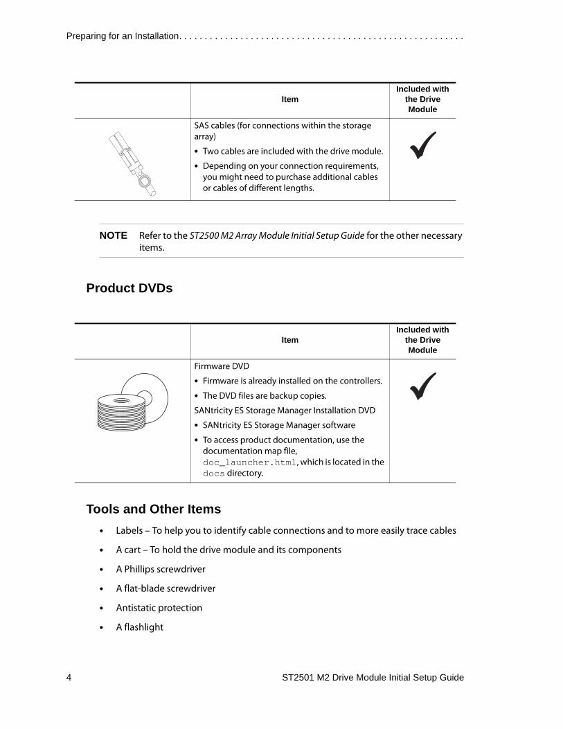
NOTE Refer to the ST2500 M2 Array Module Initial Setup Guide for the other necessary items.
Cables and Connectors
Basic Hardware and Tools ItemIncluded with
the Drive Module
DE1600 drive module with end caps that are packaged separately.
Mounting rails, clip nuts, and screws
The mounting rails that are available with the drive module are designed for an industry-standard cabinet.
ItemIncluded with
the Drive Module
Power cords
The power cords that are shipped with the drive module are for connection to an external power source, such as a wall plug. Your cabinet might have special power cords that you use instead of the power cords that are shipped with the drive module.
Preparing for an Installation. . . . . . . . . . . . . . . . . . . . . . . . . . . . . . . . . . . . . . . . . . . . . . . . . . . . . . . .
4 ST2501 M2 Drive Module Initial Setup Guide
NOTE Refer to the ST2500 M2 Array Module Initial Setup Guide for the other necessary items.
Product DVDs
Tools and Other Items• Labels – To help you to identify cable connections and to more easily trace cables
• A cart – To hold the drive module and its components
• A Phillips screwdriver
• A flat-blade screwdriver
• Antistatic protection
• A flashlight
SAS cables (for connections within the storage array)
• Two cables are included with the drive module.
• Depending on your connection requirements, you might need to purchase additional cables or cables of different lengths.
ItemIncluded with
the Drive Module
Firmware DVD
• Firmware is already installed on the controllers.
• The DVD files are backup copies.
SANtricity ES Storage Manager Installation DVD
• SANtricity ES Storage Manager software
• To access product documentation, use the documentation map file, doc_launcher.html, which is located in the docs directory.
ItemIncluded with
the Drive Module
. . . . . . . . . . . . . . . . . . . . . . . . . . . . . . . Things to Know – Taking a Quick Glance at the Hardware
ST2501 M2 Drive Module Initial Setup Guide 5
Things to Know – Taking a Quick Glance at the Hardware
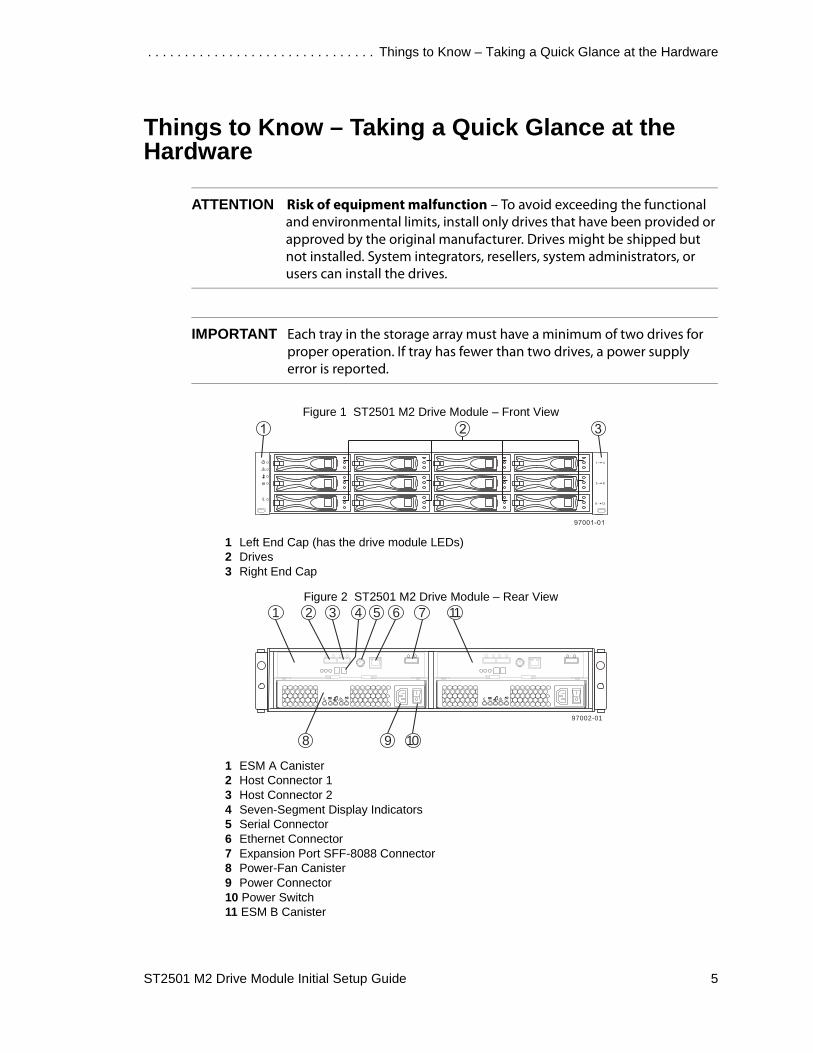
ATTENTION Risk of equipment malfunction – To avoid exceeding the functional and environmental limits, install only drives that have been provided or approved by the original manufacturer. Drives might be shipped but not installed. System integrators, resellers, system administrators, or users can install the drives.
IMPORTANT Each tray in the storage array must have a minimum of two drives for proper operation. If tray has fewer than two drives, a power supply error is reported.
Figure 1 ST2501 M2 Drive Module – Front View
1 Left End Cap (has the drive module LEDs)2 Drives3 Right End Cap
Figure 2 ST2501 M2 Drive Module – Rear View
1 ESM A Canister2 Host Connector 13 Host Connector 24 Seven-Segment Display Indicators5 Serial Connector6 Ethernet Connector7 Expansion Port SFF-8088 Connector8 Power-Fan Canister9 Power Connector10 Power Switch11 ESM B Canister
97002-01
ACDC!
ACDC!
2 3 4 5 761
98 10
11

Preparing for an Installation. . . . . . . . . . . . . . . . . . . . . . . . . . . . . . . . . . . . . . . . . . . . . . . . . . . . . . . .
6 ST2501 M2 Drive Module Initial Setup Guide

ST2501 M2 Drive Module Initial Setup Guide 7
Step 2 – Installing the Drive Module
Things to Know – General Installation
IMPORTANT If you are installing the drive module in a cabinet with other trays, make sure that the combined power requirements of the drive module and the other trays do not exceed the power capacity of your cabinet.
• Special site preparation is not required for this drive module beyond what is normally found in a computer lab environment.
• The power supplies meet standard voltage requirements for both domestic and worldwide operation.
• If you are installing drive modules and the array module at the same time, take these precautions:
■ Install the array module in a location within the cabinet that lets you evenly distribute the drive modules around the array module.
■ Keep as much weight as possible in the bottom half of the cabinet.
Navigational Aid
“Things to Know – General Installation“ Page 7
“For Additional Information“ Page 8
“Steps to Install – Drive Module“ Page 8
“Steps to Install – Drives“ Page 15
“Things to Know – Connecting the Power Cords“ Page 16
“Steps to Connect – Power Cords“ Page 17

Installing the Drive Module . . . . . . . . . . . . . . . . . . . . . . . . . . . . . . . . . . . . . . . . . . . . . . . . . . . . . . . .
8 ST2501 M2 Drive Module Initial Setup Guide
IMPORTANT After you install the drive module, you might replace drives or install additional drives. If you replace or add more than one drive without powering down the drive module, install the drives one at a time. Wait 10 seconds after you insert each drive before inserting the next one.
ATTENTION Possible hardware damage – To prevent electrostatic discharge damage to the tray, use proper antistatic protection when handling tray components.
For Additional InformationRefer to the Storage System Site Preparation Guide for important considerations about cabinet installation.
Steps to Install – Drive Module
WARNING (W08) Risk of bodily injury –
Two persons are required to safely lift the component.
WARNING (W05) Risk of bodily injury – If the bottom half of the cabinet is empty, do not install components in the top half of the cabinet. If the top half of the cabinet is too heavy for the bottom half, the cabinet might fall and cause bodily injury. Always install a component in the lowest available position in the cabinet.
You can install the drive module into an industry standard cabinet.
This procedure describes how to install the mounting rails into an industry standard cabinet.
. . . . . . . . . . . . . . . . . . . . . . . . . . . . . . . . . . . . . . . . . . . . . . . . . . . . . Steps to Install – Drive Module
ST2501 M2 Drive Module Initial Setup Guide 9
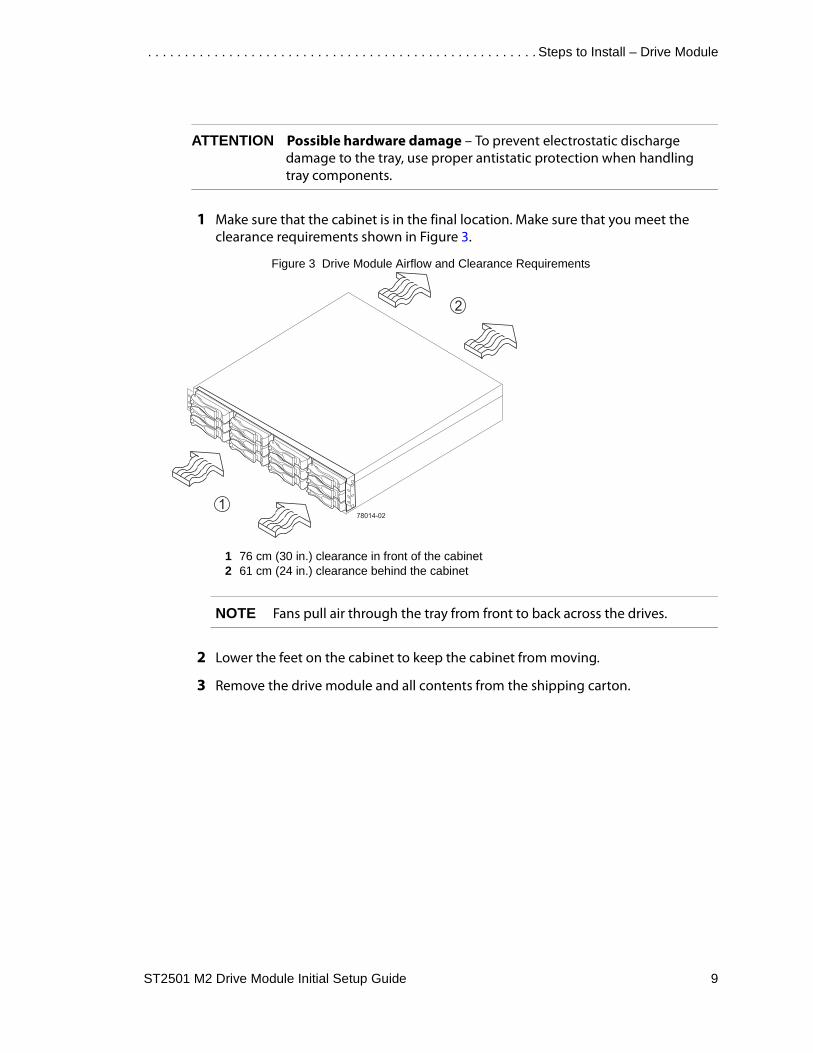
ATTENTION Possible hardware damage – To prevent electrostatic discharge damage to the tray, use proper antistatic protection when handling tray components.
1 Make sure that the cabinet is in the final location. Make sure that you meet the clearance requirements shown in Figure 3.
Figure 3 Drive Module Airflow and Clearance Requirements
1 76 cm (30 in.) clearance in front of the cabinet2 61 cm (24 in.) clearance behind the cabinet
NOTE Fans pull air through the tray from front to back across the drives.
2 Lower the feet on the cabinet to keep the cabinet from moving.
3 Remove the drive module and all contents from the shipping carton.

Installing the Drive Module . . . . . . . . . . . . . . . . . . . . . . . . . . . . . . . . . . . . . . . . . . . . . . . . . . . . . . . .
10 ST2501 M2 Drive Module Initial Setup Guide
4 Position the mounting rails in the cabinet (Figure 4).
Figure 4 Positioning the Mounting Rails in the Cabinet
1 Mounting Rail2 Existing Tray3 Clearance Above and Below the Existing Tray4 Screws for Securing the Mounting Rail to the Cabinet (Front and Rear)5 Industry Standard Cabinet
■ If you are installing the mounting rails above an existing tray, position the mounting rails directly above the tray.
■ If you are installing the mounting rails below an existing tray, allow 8.8-cm (3.5-in.) vertical clearance for a drive module or an array module.

. . . . . . . . . . . . . . . . . . . . . . . . . . . . . . . . . . . . . . . . . . . . . . . . . . . . . Steps to Install – Drive Module
ST2501 M2 Drive Module Initial Setup Guide 11
5 Attach the mounting rails to the cabinet by performing these substeps (Figure 5):
a Make sure that the adjustment screws on the mounting rail are loose so that the mounting rail can extend or contract as needed.
Figure 5 Attaching the Mounting Rails to the Cabinet
1 Cabinet Mounting Holes2 Adjustment Screws for Locking the Mounting Rail Length3 Mounting Rails4 Clip for Securing the Rear of the Drive Module
b Place the mounting rail inside the cabinet, and extend the mounting rail until the flanges on the mounting rail touch the inside of the cabinet.
c Make sure that the alignment spacers on the front flange of the mounting rail fit into the mounting holes in the cabinet (Figure 6 on page 12).

Installing the Drive Module . . . . . . . . . . . . . . . . . . . . . . . . . . . . . . . . . . . . . . . . . . . . . . . . . . . . . . . .
12 ST2501 M2 Drive Module Initial Setup Guide
The front flange of each mounting rail has two alignment spacers. The alignment spacers are designed to fit into the mounting holes in the cabinet. The alignment spacers help position and hold the mounting rail.
Figure 6 Alignment Spacers on the Mounting Rail
1 Alignment Spacers
d Insert one M5 screw through the front of the cabinet and into the top captured nut in the mounting rail. Tighten the screw.
e Insert two M5 screws through the rear of the cabinet and into the captured nuts in the rear flange in the mounting rail. Tighten the screw.
f Tighten the adjustment screws on the mounting rail.
g Repeat substep a through substep f to install the second mounting rail.

. . . . . . . . . . . . . . . . . . . . . . . . . . . . . . . . . . . . . . . . . . . . . . . . . . . . . Steps to Install – Drive Module
ST2501 M2 Drive Module Initial Setup Guide 13
6 With the help of one other person, slide the rear of the drive module onto the mounting rails. The rear edge of the drive module must fit into the clip on the mounting rail. The drive module is correctly aligned when these conditions are met:
■ The mounting holes on the front flanges of the drive module align with the mounting holes on the front of the mounting rails.
■ The rear edge of the drive module sheet metal fits into the clip on the mounting rail (Figure 7).
■ The holes in the drive module sheet metal for the rear hold-down screws align with the captured nuts in the side of the mounting rails.
Figure 7 Sliding the Drive Module into the Clip on the Mounting Rail
1 Mounting Rail2 Clip3 Partial View of the Drive Module Rear Sheet Metal4 Align the hole in the Drive Module sheet metal with the captured nut in the mounting rail.

Installing the Drive Module . . . . . . . . . . . . . . . . . . . . . . . . . . . . . . . . . . . . . . . . . . . . . . . . . . . . . . . .
14 ST2501 M2 Drive Module Initial Setup Guide
7 Secure the front of the drive module to the cabinet. Use the two screws to attach the flange on each side of the front of the drive module to the mounting rails (Figure 8).
a Insert one M5 screw through the bottom hole of a flange on the drive module so that the screw goes through the cabinet rail and engages the bottom captured nut in the mounting rail. Tighten the screw.
b Repeat substep a for the second flange.
Figure 8 Attaching the Front of the Drive Module
1 Screws for Securing the Front of the Drive Module
8 Secure the side of the drive module to the mounting rails by performing these substeps:
a Insert one M4 screw through the side sheet metal of the drive module into the captured nut on the side of the mounting rail. Tighten the screw.
b Repeat substep a for the other side.

. . . . . . . . . . . . . . . . . . . . . . . . . . . . . . . . . . . . . . . . . . . . . . . . . . . . . . . . . . Steps to Install – Drives
ST2501 M2 Drive Module Initial Setup Guide 15
9 Attach the plastic end caps onto the front of the drive module (Figure 9).
a Put the top of the end cap on the hinge tab that is part of the drive module mounting flange.
b Gently press on the bottom of the end cap until it snaps into place over the retainer on the bottom of the drive module mounting flange.
Figure 9 Attaching the End Caps to the DE1600 Drive Module
1 Hinge Tab2 Retainer
Steps to Install – DrivesIn some situations, the drive module might be delivered without the drives installed. Follow the steps in this procedure to install the drives. If your drive module already has drives installed, you can skip this step and go to “Things to Know – Connecting the Power Cords” on page 16.
ATTENTION Risk of equipment malfunction – To avoid exceeding the functional and environmental limits, install only drives that have been provided or approved by the original manufacturer. Drives might be shipped but not installed. System integrators, resellers, system administrators, or users can install the drives.
NOTE The installation order is from top to bottom and left to right. The installation order is important because the drives might already contain configuration information that depends upon the correct sequence of the drives in the tray.

Installing the Drive Module . . . . . . . . . . . . . . . . . . . . . . . . . . . . . . . . . . . . . . . . . . . . . . . . . . . . . . . .
16 ST2501 M2 Drive Module Initial Setup Guide
1 Beginning with the first drive slot in the upper-left side of the drive module, place the drive on the slot guides, and slide the drive all the way into the slot.
2 Push the drive handle to the right to lock the drive securely in place.
Figure 10 Installing a Drive
1 Drive Handle
NOTE In some applications, the drive handle might have the hinge on the right.
3 Install the second drive to the right of the first drive.
4 Install the other drives from left to right and, as you fill each drive row, top to bottom.
Things to Know – Connecting the Power Cords• For each AC power connector on the drive module, make sure that you use a
separate power source in the cabinet. Connecting to independent power sources maintains power redundancy.
• To ensure proper cooling and assure availability, the drive module always uses two power supplies.
• You can use the power cords shipped with the drive module with typical outlets used in the destination country, such as a wall receptacle or an uninterruptible power supply (UPS). These power cords, however, are not intended for use in most EIA-compliant cabinets.
IMPORTANT Make sure that you do not turn on the power to the drive module until this initial setup guide instructs you to do so. For the correct procedure for turning on the power, see “Steps to Turn On – Power” on page 31.
97006-01
1

. . . . . . . . . . . . . . . . . . . . . . . . . . . . . . . . . . . . . . . . . . . . . . . . . . . Steps to Connect – Power Cords
ST2501 M2 Drive Module Initial Setup Guide 17
Steps to Connect – Power Cords1 Make sure that the circuit breakers in the cabinet are turned off.
2 Make sure that both of the Power switches on the drive modules are turned off.
3 Connect the primary power cords from the cabinet to the external power source.
4 Connect a cabinet power ladder (or power cords specific to your particular cabinet) to the AC power connector on each power-fan canister in the drive module.
5 If you are installing other drive modules in the cabinet, connect a power cord to each power-fan canister in the drive modules.

Installing the Drive Module . . . . . . . . . . . . . . . . . . . . . . . . . . . . . . . . . . . . . . . . . . . . . . . . . . . . . . . .
18 ST2501 M2 Drive Module Initial Setup Guide

ST2501 M2 Drive Module Initial Setup Guide 19
Step 3 – Connecting the Drive Module to the Array Module
Key Terms
drive channelThe path for the transfer of data between the controllers and the drives in the storage array.
Navigational Aid
“Key Terms“ Page 19
“Things to Know – ST2500 M2 Array Modules“ Page 20
“Things to Know – Drive Module“ Page 20
“Things to Know – Connecting the Drive Module to an Array Module“
Page 21
“Things to Know – Connecting the Drive Module to Another Drive Module”
Page 21
“Things to Know – Storage Array Configuration Specifications“ Page 22
“Things to Know – Drive Module Cable Labeling“ Page 23
“Steps to Connect – Drive Modules with the Power Off“ Page 23
“Steps to Connect – Drive Module with the Power On“ Page 24
“Things to Know – Basic Cabling Configurations“ Page 25

Connecting the Drive Module to the Array Module . . . . . . . . . . . . . . . . . . . . . . . . . . . . . . . . . . . . . .
20 ST2501 M2 Drive Module Initial Setup Guide
Things to Know – ST2500 M2 Array ModulesThe ST2501 M2 drive module connects to a ST2500 M2 Array Module.
Figure 11 shows the location of the expansion connectors on the controllers in a ST2500 M2 array module.
Figure 11 Drive Expansion Connectors on the Controllers in a ST2500 M2 Array Module
1 Controllers2 SAS Drive Expansion Connectors
• Each controller has one drive expansion connector. You connect drive modules to your array module through the drive expansion connector.
• The cables from the controllers in the array module to the drive modules are SAS cables.
• Controller A contains drive channel 1.
• Controller B contains drive channel 2.
Things to Know – Drive Module
IMPORTANT If you add more drive modules than the storage array supports, the storage array becomes invalid. You cannot perform configuration operations, but you can continue to transfer I/O data to the existing volumes.
Each storage array supports a specific number of drive modules. See “Things to Know – Storage Array Configuration Specifications” on page 22 for the number of drive modules that the storage array supports. If you are setting up a new storage array, refer to the ST2500 M2 Array Module Initial Setup Guide.
98008-01
1 2 1 2
. . . . . . . . . . . . . . . . . . . . . . . . Things to Know – Connecting the Drive Module to an Array Module
ST2501 M2 Drive Module Initial Setup Guide 21
If you are adding the drive module to an existing storage array, look at the storage array profile for your storage array. The storage array profile shows information about the number of drive modules that are supported by your storage array. The storage array profile shows this information:
• The number of drive modules that are currently attached to the storage array
• The number of drive modules that you are allowed to add to the storage array
Things to Know – Connecting the Drive Module to an Array Module
You can connect a drive module to a new array module or to an existing array module. Before you connect a drive module to an existing array module, you must answer these questions:
• How many drive modules does this array module support? See “Things to Know – Storage Array Configuration Specifications“ on page 22.
• What is the cabling configuration for the storage array? See “Things to Know – Basic Cabling Configurations“ on page 25.
• Is the storage array receiving power? No, see “Things to Know – General Installation“ on page 7.
• Is the storage array transferring I/O data? Yes, see “Things to Know – Connecting the Power Cords“ on page 16.
Things to Know – Connecting the Drive Module to Another Drive Module
Each ESM in a drive module has three SAS connectors. Below two of the connectors is an arrow pointing up. Below the expansion connector on the far right is an arrow pointing down. When connecting from an ESM in one drive module to an ESM in another drive module, make sure that you use connectors with arrows pointing in opposite directions.

Connecting the Drive Module to the Array Module . . . . . . . . . . . . . . . . . . . . . . . . . . . . . . . . . . . . . .
22 ST2501 M2 Drive Module Initial Setup Guide
Things to Know – Storage Array Configuration Specifications
Item Specification
Number of controllers One or two
Number of host connectors Two SAS host connectors for the following:
• ST2500 M2 array module with 12 drives
• ST2500 M2 array module with 24 drives
Number of drive modules Up to seven additional drive modules, depending on the number of drives (12 or 24) in the ST2500 M2 array module
Maximum number of drives • 96 (12 or 24 drives in the array module and 12 drives in each of six or seven drive modules) in a duplex configuration
• 36 (24 drives in the array module) in a simplex configuration
Maximum number of volumes per storage array
1024
Maximum number of storage partitions
64
Maximum number of volumes per storage partition
256
Cluster support Windows Server 2003 SP2, R2 and Windows Server 2008 operating systems: MSCS
Linux SLES 10 sp3, SLES 11, and Open-iscsi operating systems: SteelEye; SUSE OES v2 (with SLES 10 sp3 only)
Linux Red Hat 4.8 and Red Hat 5.4 operating systems (SteelEye is not supported with Red Hat Version 4.0 IA64): Red Hat native (Heartbeat)
HP-UX v11.23, and HP-UX v11.31 (PA-RISC and IA64) operating systems: MC Service Guard
Solaris 10 and Solaris 11 (x86) operating systems: Sun Cluster
Maximum number of snapshot copies per volume
8
Maximum number of snapshot copies per storage array
256

. . . . . . . . . . . . . . . . . . . . . . . . . . . . . . . . . . . . . . . .Things to Know – Drive Module Cable Labeling
ST2501 M2 Drive Module Initial Setup Guide 23
Things to Know – Drive Module Cable LabelingLabels for the drive cables identify which controller ports and which ESM connections in a drive module that you use when you attach cables between a controller and the drive module. Cable labels are useful if you need to disconnect cables to service a controller. Attach a label to each end of the cable. Use this design to create labels for drive cables:
• Controller ID (for example, controller A)
• Drive channel number and port ID in the controller (for example, drive channel 1, port 4)
• ESM ID (for example, ESM A)
• ESM port ID (for example, 1A or 1B)
• Drive module ID
In this example, the cable connection has the following characteristics:
• Controller A, drive channel 1
• Controller A, port 1
• Drive module 1
• ESM A (which is the left ESM), out port
Using this design, the label should include this information:
CtA-Dch1, Dm1-ESM_A (left), 1A
Steps to Connect – Drive Modules with the Power Off
1 If a black, plastic plug is in the drive expansion connector of controller A in the array module, remove it.
2 Plug one end of the cable into the drive expansion connector on the array module.
3 Plug the other end of the cable into the connector with an up arrow on the ESM in the drive module.
4 Are you adding more drive modules?
■ Yes – Continue with step 5.
■ No – Continue with step 8 on page 24.
5 From the first drive module, plug one end of the cable into the connector with the down arrow.

Connecting the Drive Module to the Array Module . . . . . . . . . . . . . . . . . . . . . . . . . . . . . . . . . . . . . .
24 ST2501 M2 Drive Module Initial Setup Guide
IMPORTANT Each ESM in the drive module has three SAS connectors. Two connectors show an up arrow; the other connector shows a down arrow. When connecting from an ESM in one drive module to an ESM in another drive module, connect from a down arrow to an up arrow. If the cable is plugged into two connectors with arrows pointing in the same direction, communication between the two drive modules is lost.
6 Plug the other end of the cable into the connector with an up arrow on the next drive module.
7 Repeat step 5 on page 23 through step 6 for each drive module that you intend to add to the storage array.
8 Repeat step 1 on page 23 through step 7 for controller B.
Steps to Connect – Drive Module with the Power On
1 Is the storage array transferring I/O data?
■ Yes – Go to step 2.
■ No – Go to step 5.
2 Can you stop transferring all I/O data to the storage array?
■ Yes – Go to step 3. Supervision from your Customer and Technical Support representative is not required.
■ No – Contact your Customer and Technical Support representative before connecting a drive module to a storage array that is transferring I/O data. The Customer and Technical Support representative will help you connect the drive module to a storage array that is transferring I/O data.
3 Stop all I/O activity to the storage array.
4 Are you adding the drive module to a storage array with existing drive modules?
■ Yes – Go to step 5.
■ No – Go to step 8 on page 25.
5 Plug one end of the cable into the drive expansion connector on the array module.

. . . . . . . . . . . . . . . . . . . . . . . . . . . . . . . . . . . . . . . .Things to Know – Basic Cabling Configurations
ST2501 M2 Drive Module Initial Setup Guide 25
IMPORTANT Each ESM in the drive module has three SAS connectors. Two connectors show an up arrow; the other connector shows a down arrow. When connecting from an ESM in one drive module to an ESM in another drive module, connect from a down arrow to an up arrow. If the cable is plugged into two connectors with arrows pointing in the same direction, communication between the two drive modules is lost.
6 Plug the other end of the cable into the connector with an up arrow on the ESM in the drive module.
7 Are you adding more drive modules?
■ Yes – Go to step 5.
■ No – Go to step 8.
8 From the first drive module, plug one end of the cable into the connector with the down arrow.
9 Plug the other end of the cable into the connector with an up arrow on the next drive module.
10 Repeat step 8 through step 9 for each drive module that you intend to add to the storage array.
11 Repeat step 5 through step 10 for controller B.
Things to Know – Basic Cabling ConfigurationsYou have many options for attaching cables in your storage array configuration. Use these basic configurations as a guide to configure your storage array.
Depending on the number of drive modules that you need to connect, see the applicable figure listed in Table 1.
Table 1 Cabling Configurations
Cabling Configuration Figure
Array module above one drive module Figure 12 on page 26
Array module between two drive modules Figure 13 on page 26
Array module with three drive modules Figure 14 on page 26
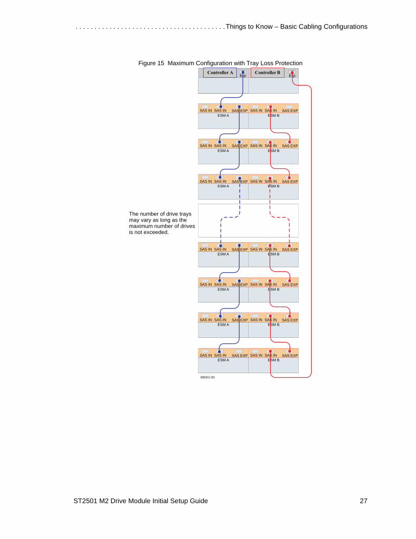
Maximum configuration with tray loss protection Figure 15 on page 27

Connecting the Drive Module to the Array Module . . . . . . . . . . . . . . . . . . . . . . . . . . . . . . . . . . . . . .
26 ST2501 M2 Drive Module Initial Setup Guide
Figure 12 Array Module Above the Drive Module
Figure 13 Array Module Between Two Drive Modules
Figure 14 Array Module With Three Drive Modules
ExpExpController A Controller B
ESM A ESM B
98010-01
SAS EXP SAS EXPSAS IN SAS IN SAS IN SAS IN
98010-02
ExpExpController A Controller B
SAS EXPSAS IN
ESM ASAS EXPSAS IN
ESM B
SAS EXPSAS INESM A
SAS EXPSAS INESM B
SAS IN SAS IN
SAS IN SAS IN
ExpExpController A Controller B
SAS EXPSAS IN
ESM ASAS EXPSAS IN
ESM B
SAS EXPSAS IN
ESM ASAS EXPSAS IN
ESM B
SAS EXPSAS INESM A
SAS EXPSAS INESM B
98010-03
SAS IN SAS IN
SAS IN SAS IN
SAS IN SAS IN
. . . . . . . . . . . . . . . . . . . . . . . . . . . . . . . . . . . . . . . .Things to Know – Basic Cabling Configurations
ST2501 M2 Drive Module Initial Setup Guide 27
Figure 15 Maximum Configuration with Tray Loss Protection
1A 1B 2A 2B
ESM A ESM B
1A 1B 2A 2B
ESM A ESM B
1A 1B 2A 2B
ESM A ESM B
1A 1B 2A 2B
ESM A ESM B
1A 1B 2A 2B
ESM A ESM B
1A 1B 2A 2B
ESM A ESM B
ExpChamonix A Chamonix B
Exp
1A 1B 2A 2B
The number of drive traysmay vary as long as themaximum number of drivesis not exceeded.
Controller A Controller B
98002-00
ESM A ESM BSAS EXP SAS EXPSAS IN SAS IN SAS IN SAS IN
SAS EXP SAS EXPSAS IN SAS IN SAS IN SAS IN
SAS EXP SAS EXPSAS IN SAS IN SAS IN SAS IN
SAS EXP SAS EXPSAS IN SAS IN SAS IN SAS IN
SAS EXP SAS EXPSAS IN SAS IN SAS IN SAS IN
SAS EXP SAS EXPSAS IN SAS IN SAS IN SAS IN
SAS EXP SAS EXPSAS IN SAS IN SAS IN SAS IN

Connecting the Drive Module to the Array Module . . . . . . . . . . . . . . . . . . . . . . . . . . . . . . . . . . . . . .
28 ST2501 M2 Drive Module Initial Setup Guide
ST2501 M2 Drive Module Initial Setup Guide 29
Step 4 – What to Do Next
If you are adding a drive module to a new storage array, make sure you complete these tasks by using the storage management software:
• Set a password
• Configure the email alerts and the Simple Network Management Protocol (SNMP) alerts
• Enable the premium features
• Configure the hosts
• Configure the storage
If you are adding a drive module to an existing storage array, make sure you complete these tasks by using the storage management software:
• Check the ESM firmware level on the new drive module. If the ESM firmware level is different from the ESM firmware level on the existing drive modules, use the storage management software to upgrade the ESM firmware level to the highest available level for the type of ESM.
• Add the free capacity (new drives) to your storage array.
• Configure the storage.
For more information, refer to the online help topics in the storage management software or to the ST2500 M2 Array Module Initial Setup Guide.

What to Do Next . . . . . . . . . . . . . . . . . . . . . . . . . . . . . . . . . . . . . . . . . . . . . . . . . . . . . . . . . . . . . . . .
30 ST2501 M2 Drive Module Initial Setup Guide

ST2501 M2 Drive Module Initial Setup Guide 31
Step 5 – Turning on the Power and Checking for Problems
Steps to Turn On – Power
IMPORTANT You must turn on the power to all connected drive modules before you turn on the power to the array module. Performing this action ensures that the controllers recognize each attached drive module.
Access the Power switches from the rear of the storage array.
1 Turn off the Power switches on each power-fan canister in all of the newly installed drive modules.
2 Make sure that all of the power cords are connected.
3 If the main circuit breaker switches in the cabinet are not already turned on, turn on the circuit breaker switches now.
Navigational Aid
“Steps to Turn On – Power” Page 31
“Steps to Check for Problems – Drive Module” Page 32
“Things to Know – LEDs on the Drive Module” Page 33

Turning on the Power and Checking for Problems . . . . . . . . . . . . . . . . . . . . . . . . . . . . . . . . . . . . . .
32 ST2501 M2 Drive Module Initial Setup Guide
4 Turn on the Power switch on each power-fan canister in all of the newly installed drive modules.
Figure 16 Location of the Power Switches on the Drive Module
1 Power Switches
While power is being applied to the drive modules, the LEDs on the front and the rear of the drive modules turn on and turn off intermittently.
The drive modules might take several minutes to turn on completely. Wait until the drive modules are completely turned on before turning on the power to the array module.
5 Turn on the Power switch on each power-fan canister in the array module.
Steps to Check for Problems – Drive ModuleRefer to the following figures for the location of the LEDs on the canisters:
• Figure 17, “LEDs on the Left End Cap” on page 33
• Figure 18, “LEDs on the Drive” on page 34
• Figure 19, “LEDs on the ESM Canister” on page 35
• Figure 20, “LEDs on the Power-Fan Canister“ on page 37
The LEDs let you know that your hardware devices are fully operational or whether a fault condition exists.
1 Make sure that all of the LEDs show normal operation. See “Things to Know – LEDs on the Drive Module” on page 33 for a description of the LEDs on the drive module.
2 Do you see any amber LEDs on the drive module?
■ Yes – Review the installation steps that you have performed to this point. Make sure you have performed the steps correctly. If necessary, contact your Customer and Technical Support representative for assistance.
■ No – Go to “What to Do Next” on page 29.
97002-03
1 1
. . . . . . . . . . . . . . . . . . . . . . . . . . . . . . . . . . . . . . . . . . Things to Know – LEDs on the Drive Module
ST2501 M2 Drive Module Initial Setup Guide 33
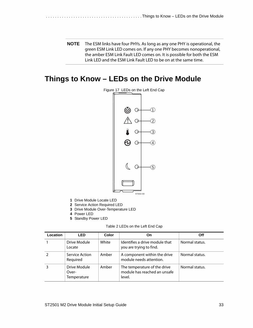
NOTE The ESM links have four PHYs. As long as any one PHY is operational, the green ESM Link LED comes on. If any one PHY becomes nonoperational, the amber ESM Link Fault LED comes on. It is possible for both the ESM Link LED and the ESM Link Fault LED to be on at the same time.
Things to Know – LEDs on the Drive ModuleFigure 17 LEDs on the Left End Cap
1 Drive Module Locate LED2 Service Action Required LED3 Drive Module Over-Temperature LED4 Power LED5 Standby Power LED
Table 2 LEDs on the Left End Cap
Location LED Color On Off
1 Drive Module Locate
White Identifies a drive module that you are trying to find.
Normal status.
2 Service Action Required
Amber A component within the drive module needs attention.
Normal status.
3 Drive Module Over-Temperature
Amber The temperature of the drive module has reached an unsafe level.
Normal status.
!
1
2
3
4
5
97004-00

Turning on the Power and Checking for Problems . . . . . . . . . . . . . . . . . . . . . . . . . . . . . . . . . . . . . .
34 ST2501 M2 Drive Module Initial Setup Guide
Figure 18 LEDs on the Drive
1 Drive Power LED2 Drive Service Action Required LED3 Drive Service Action Allowed LED
Table 3 LEDs on the Drive
4 Power Green Power is present. Power is not present.
5 Standby Power Green The drive module is in Standby Power mode.
The drive module is not in Standby Power mode.
Location LED Color On Blinking Off
1 Drive Power Green The power is turned on, and the drive is operating normally.
Drive I/O activity is taking place.
The power is turned off.
2 Drive Service Action Required
Amber An error has occurred.
Normal status.
3 Drive Service Action Allowed
Blue The drive canister can be removed safely from the drive module.
The drive canister cannot be removed safely from the drive module.
Location LED Color On Off

. . . . . . . . . . . . . . . . . . . . . . . . . . . . . . . . . . . . . . . . . . Things to Know – LEDs on the Drive Module
ST2501 M2 Drive Module Initial Setup Guide 35
Table 4 Drive State Represented by LEDs
Figure 19 LEDs on the ESM Canister
1 Host Link 1 Fault LED2 Host Link 1 Active LED3 Host Link 2 Fault LED4 Host Link 2 Active LED5 Ethernet Link Active LED 6 Ethernet Link Rate LED7 ESM Expansion Link Fault LED8 ESM Expansion Link Active LED9 ESM Service Action Allowed LED 10 ESM Service Action Required LED11 ESM Power LED12 Seven-Segment Tray ID
Table 5 LEDs on the ESM Canister
Drive State Drive Power LED (Green)
Drive Service Action Required LED (Amber)
Power is not applied. Off Off
Normal operation – The power is turned on, but drive I/O activity is not occurring.
On Off
Normal operation – Drive I/O activity is occurring. Blinking Off
Service action required – A fault condition exists, and the drive is offline.
On On
Location LED Color On Off
1 Host Link 1 Fault Amber At least one PHY of the four connectors is working, but another PHY cannot establish the same link to the device connected to the Host IN port connector.
No link error has occurred.

Turning on the Power and Checking for Problems . . . . . . . . . . . . . . . . . . . . . . . . . . . . . . . . . . . . . .
36 ST2501 M2 Drive Module Initial Setup Guide
2 Host Link 1 Active Green At least one of the four PHYs in the IN port is working, and a link exists to the device connected to the Host IN connector.
A link error has occurred.
3 Host Link 2 Fault Amber At least one PHY of the four connections is working, but another PHY cannot establish the same link to the device connected to the Host IN port connector
No link error has occurred.
4 Host Link 2 Active Green At least one of the four PHYs in the IN port is working, and a link exists to the device connected to the Host IN connector.
A link error has occurred.
5 Ethernet Link Active
Green The link is up. (The LED blinks when there is activity.)
The link is not active.
6 Ethernet Link Rate Green There is a 100BASE-T rate. There is a 10BASE-T rate.
7 ESM Expansion Link Fault
Amber At least one of the four PHYs in the OUT port is working, but another PHY cannot establish the same link to the Expansion OUT connector.
Normal status.
8 ESM Expansion Link Active
Green At least one of the four PHYs in the OUT port is working, and a link exists to the device connected to the Expansion OUT connector.
A link error has occurred.
9 ESM Service Action Allowed
Blue The ESM can be removed safely from the drive module.
The ESM cannot be removed safely from the drive module.
10 ESM Service Action Required
Amber A fault exists within the ESM. (This LED defaults on at power up. This LED turns off after the software has completed its power up self-test sequence.)
Normal status.
11 ESM Power Green 12V power to the ESM is present.
Power is not present to the ESM.
Location LED Color On Off

. . . . . . . . . . . . . . . . . . . . . . . . . . . . . . . . . . . . . . . . . . Things to Know – LEDs on the Drive Module
ST2501 M2 Drive Module Initial Setup Guide 37
Figure 20 LEDs on the Power-Fan Canister
1 Standby Power LED2 Power-Fan DC Power LED3 Power-Fan Service Action Allowed LED4 Power-Fan Service Action Required LED5 Power-Fan AC Power LED
Table 6 LEDs on the Power-Fan Canister
12 Seven-Segment Tray ID
Green See note. Not applicable.
*For more information about the Seven-Segment Tray IDs, see “Tray ID Diagnostic Codes on the Seven-Segment Display” on page 38.
Location LED Color On Off
1 Standby Power Green The drive module is in Standby mode, and DC power is not available.
The drive module is not in Standby mode, and DC power is available.
2 Power-Fan DC Power
Green DC power from the power-fan canister is available.
DC power from the power-fan canister is not available.
3 Power-Fan Service Action Allowed
Blue The power-fan canister can be removed safely from the drive module.
The power-fan canister cannot be removed safely from the drive module.
4 Power-Fan Service Action Required
Amber A fault exists within the power-fan canister.
Normal status.
5 Power-Fan AC Power
Green AC power to the power-fan canister is present.
AC power to the power-fan canister is not present.
Location LED Color On Off
ACDC!
1 2 3 4 5
97003-01

Turning on the Power and Checking for Problems . . . . . . . . . . . . . . . . . . . . . . . . . . . . . . . . . . . . . .
38 ST2501 M2 Drive Module Initial Setup Guide
Tray ID Diagnostic Codes on the Seven-Segment DisplayDuring normal operation, the tray ID display on each ESM displays the drive module ID. The Diagnostic LED (lower-digit decimal point) comes on when the display is used for diagnostic codes and goes off when the display is used to show the tray ID.
NOTE If a power-on or reset occurs, the Diagnostic LED, the Heartbeat LED (upper-digit decimal point), and all seven segments of both digits come on. The Diagnostic LED remains on until the drive module ID appears.
Table 7 Supported Diagnostic Codes
Diagnostic Code ESM State Description
.8, 8., or 88 Suspended This ESM is being held in reset by another ESM.
L0 Suspended The ESM types are mismatched.
L2 Suspended A persistent memory error has occurred.
L3 Suspended A persistent hardware error has occurred.
L9 Suspended An over-temperature condition has been detected in either the ESM or the power supply.
LL Suspended The midplane SBB VPD EEPROM cannot be accessed.
Ln Suspended The canister is not valid for this drive module.
LP Suspended Drive port mapping tables are not found.
H0 Suspended An ESM Fibre Channel interface failure has occurred.
H1 Suspended An SFP transceiver speed mismatch (a 2-Gb/s SFP transceiver is installed when the drive module is operating at 4 Gb/s) indicates that an SFP transceiver must be replaced. Look for the SFP transceiver with a blinking amber LED.
H2 Suspended The ESM configuration is invalid or incomplete, and it operates in a Degraded state.
H3 Suspended The maximum number of ESM reboot attempts has been exceeded.
H4 Suspended This ESM cannot communicate with the alternate ESM.
H5 Suspended A midplane harness failure has been detected in the drive module.
H6 Suspended An ESM firmware failure has been detected.
H8 SFP transceivers are present in currently unsupported ESM slots, either 2A or 2B. Secondary trunking SFP transceiver slots 2A and 2B are not supported. Look for the SFP transceiver with the blinking amber LED, and remove it.
H9 A non-catastrophic hardware failure has occurred. The ESM is operating in a Degraded state.
J0 Suspended The ESM canister is incompatible with the drive module firmware.
. . . . . . . . . . . . . . . . . . . . . . . . . . . . . . . . . . . . . . . . . . Things to Know – LEDs on the Drive Module
ST2501 M2 Drive Module Initial Setup Guide 39
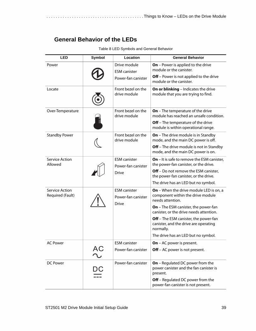
General Behavior of the LEDsTable 8 LED Symbols and General Behavior
LED Symbol Location General Behavior
Power Drive module
ESM canister
Power-fan canister
On – Power is applied to the drive module or the canister.
Off – Power is not applied to the drive module or the canister.
Locate Front bezel on the drive module
On or blinking – Indicates the drive module that you are trying to find.
Over-Temperature Front bezel on the drive module
On – The temperature of the drive module has reached an unsafe condition.
Off – The temperature of the drive module is within operational range.
Standby Power Front bezel on the drive module
On – The drive module is in Standby mode, and the main DC power is off.
Off – The drive module is not in Standby mode, and the main DC power is on.
Service Action Allowed
ESM canister
Power-fan canister
Drive
On – It is safe to remove the ESM canister, the power-fan canister, or the drive.
Off – Do not remove the ESM canister, the power-fan canister, or the drive.
The drive has an LED but no symbol.
Service Action Required (Fault)
ESM canister
Power-fan canister
Drive
On – When the drive module LED is on, a component within the drive module needs attention.
On – The ESM canister, the power-fan canister, or the drive needs attention.
Off – The ESM canister, the power-fan canister, and the drive are operating normally.
The drive has an LED but no symbol.
AC Power ESM canister
Power-fan canister
On – AC power is present.
Off – AC power is not present.
DC Power Power-fan canister On – Regulated DC power from the power canister and the fan canister is present.
Off – Regulated DC power from the power-fan canister is not present.

Turning on the Power and Checking for Problems . . . . . . . . . . . . . . . . . . . . . . . . . . . . . . . . . . . . . .
40 ST2501 M2 Drive Module Initial Setup Guide
Service Action LEDs
ATTENTION Possible loss of data access – Never remove any canister unless the appropriate Service Action Allowed LED is turned on.
Each canister in the drive module has two service action LEDs.
• Service Action Required LED – This LED comes on to indicate that a condition exists that requires service.
• Service Action Allowed LED – This LED comes on when it is safe to remove a failed canister. If there are data availability dependencies or other conditions that dictate that a canister should not be removed, the Service Action Allowed LED stays off. The Service Action Allowed LED automatically comes on or goes off as conditions change.
IMPORTANT If the Service Action Required LED is on but the Service Action Allowed LED is off for a particular canister, you might need to service another canister first. Check your storage management software to determine the action that you should take.
NOTE In most cases, the Service Action Allowed LED comes on when the Service Action Required LED is on for a canister.
Link Service Action Required (Fault)
ESM canister On – The cable is attached and at least one lane has a link-up status, but one lane has a link-down status.
Off – The cable is not attached, the cable is attached and all lanes have a link-up status, or the cable is attached and all lanes have a link-down status.
Link Up Two LEDs above each expansion connector
ESM canister On – The cable is attached and at least one lane has a link-up status.
Off – The cable is not attached, or the cable is attached and all lanes have a link-down status.
LED Symbol Location General Behavior

ST2501 M2 Drive Module Initial Setup Guide FCC-1
Regulatory Compliance Statements
FCC Radio Frequency Interference StatementThis equipment has been tested and found to comply with the limits for a Class A digital device, pursuant to Part 15 of the Federal Communications Commission (FCC) Rules. These limits are designed to provide reasonable protection against harmful interference in a commercial installation. This equipment generates, uses, and can radiate radio frequency energy and, if not installed and used in accordance with the instructions, may cause harmful interference to radio communications. Operation of this equipment in a residential area is likely to cause harmful interference, in which case the user will be required to correct the interference at his/her own expense.
LSI Corporation, and Sun Microsystems, Inc. are not responsible for any radio or television interference caused by unauthorized modification of this equipment or the substitution or attachment of connecting cables and equipment other than those specified by LSI and Sun. It is the user’s responsibility to correct interference caused by such unauthorized modification, substitution, or attachment.
Laser Products StatementThis equipment uses Small Form-factor Pluggable (SFP) optical transceivers, which are unmodified Class 1 laser products pursuant to 21 CFR, Subchapter J, Section 1040.10. All optical transceivers used with this product are required to be 21 CFR certified Class 1 laser products. For outside the USA, this equipment has been tested and found compliant with Class 1 laser product requirements contained in European Normalization standard EN 60825-1 1994+A11. Class 1 levels of laser radiation are not considered to be hazardous and are considered safe based upon current medical knowledge. This class includes all lasers or laser systems which cannot emit levels of optical radiation above the exposure limits for the eye under any exposure conditions inherent in the design of the laser products.
LSI and Sun are not responsible for any damage or injury caused by unauthorized modification of this equipment or the substitution or attachment of connecting cables and equipment other than those specified by LSI and Sun. It is the user’s responsibility to correct interference caused by such unauthorized modification, substitution, or attachment.

Regulatory Compliance Statements . . . . . . . . . . . . . . . . . . . . . . . . . . . . . . . . . . . . . . . . . . . . .
FCC-2 ST2501 M2 Drive Module Initial Setup Guide
This Class A digital apparatus meets all requirements of the Canadian Interference-Causing Equipment Regulations.
Cet appareil numérique de la classé A respecte toutes les exigences du Règlement sure le matèriel brouilleur du Canada.


Copyright © 2011 LSI Corporation. All rights reserved.Copyright © 2011 Sun Microsystems, Inc. All rights reserved.Printed in U.S.A.