st. joseph's college of engineering st. … thermal conductivity of the rod ... the thermal...
TRANSCRIPT
REGNO :
St. JOSEPH'S COLLEGE OF ENGINEERING
St. JOSEPH'S INSTITUTE OF TECHNOLOGY
MODEL EXAM III - December 2015
Subject : ENGINEERING PHYSICS-I Code : PH6151
Branch : Common to B.E/B.TECH Sem : I
DURATION : 3 hours MAX MARKS: 100
PART - A (10 X 2 = 20 Marks)
1. Draw the following planes in a cubic structure : ( 001 ), (100 ), (110) ,( 111 )
2. What is a melt growth?
3. A rod 0.25 m long and 0.892 x 10⁻⁴ m2 area of cross section is heated at one end through
393 K while the other end is kept at 323 K. The quantity of heat which will flow in 15
minutes along the rod is 8.811 x 10³ joules. Calculate thermal conductivity of the rod.
4. Define neutral surface and neutral axis.
5. Give the physical significance of a wave function.
6. Calculate the no. of photons emitted by a 100 watts sodium vapor lamp. Given
λ = 5893Å.
7. What is a decibel?
8. Mention the properties of ultrasonic waves.
9. Write any two differences between step-index and graded index fibre.
10. Write the condition for total internal reflection.
PART - B (5 X 16 = 80 Marks)
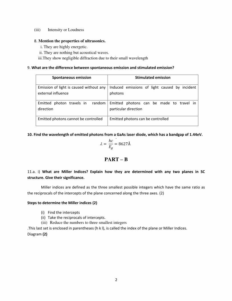
11.a i) What are Miller Indices? Explain how they are determined with any two planes in SC
structure. Give their significance. (8)
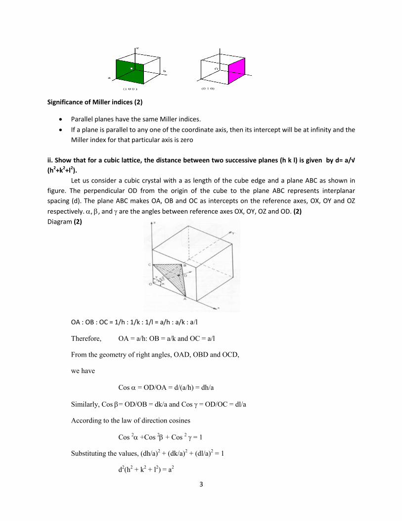
ii) Show that for a cubic lattice, the distance between two successive planes (h k l) is
given by d= a/√ (h2+k2+l2). (8)
(16)
OR
11.b Describe the structure of a HCP crystal. Give details about its atomic radius, co-
ordination number, atomic packing factor and axial ratio.
(16)
12.a Describe with relevant theory the method of determining the coefficient of thermal
conductivity of a bad conductor by Lee’s method.
(16)
OR
12.b Derive an expression for the elevation at the centre of a beam which is loaded at both
ends. Describe an experiment to determine Young’s modulus of a beam by uniform
bending.
(16)
13.a Draw a neat diagram and explain the working of Transmission electron Microscope. (16)
OR
13.b Using Schrodinger’s time independent wave equation normalize the wave functions of
electron trapped in a one dimensional potential well.
(16)
14.a Explain piezo-electric effect. Describe the piezo-electric method of producing ultrasonic
waves.
(16)
OR
14.b State and explain Sabine’s formula for reverberation time of a hall. Derive Sabine’s
formula for reverberation time.
(16)
15.a Explain the modes of vibrations of CO2 molecule. Describe the construction and working
of CO2 laser with necessary diagrams.
(16)
OR
15.b Classify the optical fibres on the basis of materials, modes of propagation and refractive
index difference.
(16)

St. JOSEPH'S COLLEGE OF ENGINEERING
St. JOSEPH'S INSTITUTE OF TECHNOLOGY MODEL
EXAM III - December 2015
Subject : ENGINEERING PHYSICS-I Code : PH6151
Branch : Common to B.E/B.TECH Sem : I
DURATION : 3 hours MAX MARKS: 100 PART - A (10 X 2 = 20 Marks)
1. Draw the following planes in a cubic structure : ( 001 ), (100 ), (110) ,( 111 )
(001) (100) (110) (111)
2. What is a melt growth? Melt growth is a process of crystallization by fusion and resolidification of the starting materials. 3. A rod 0.25 m long and 0.892 x 10⁻⁴ m2 area of cross section is heated at one end through
393 K while the other end is kept at 323 K. The quantity of heat which will flow in 15 minutes along the rod is 8.811 x 10³ joules. Calculate thermal conductivity of the rod.
tA
QxK
21
9007010892.0
25.010811.84
3
K
K = 392 Watt/metre/Kelvin
4. Define neutral surface and neutral axis.
In the middle of the beam, there is a layer which is not elongated or compressed due to bending of
the beam, this layer is called neutral surface and the line at which the neutral layer intersects the plane of
bending is called the neutral axis.
5. Give the physical significance of a wave function. i. The probability of finding a particle in space at any given instant of time is characterized by a
function ψ (x, y, z) called wave function.
ii. It relates particle and wave statistically
iii. It is a complex quantity and it does not have any meaning.
6. Calculate the no. of photons emitted by a 100 watts sodium vapor lamp. Given λ = 5893Å.
hcE
10
834
105893
10310625.6
= 3.3726 x 10
-19 J
N = Power / Energy
19103726.3
100
= 2.2965 x 10 20
per second

7. What is a decibel? A decibel is the unit of sound intensity level of a sound. Sound intensity level is measured in decibel scale (or) logarithmic scale because the response of human ear to sound is found to be logarithmic of intensity of sound. Sound intensity level in decibel
8. Mention the properties of ultrasonic waves. i. They are highly energetic.
ii. Just like ordinary sound waves, ultrasonic waves get reflected, refracted and absorbed. ii. They can be transmitted over a long distances with no appreciable loss of energy.
iv. They produce intense heating effect when passed through a substance.
9. Write any two differences between step-index and graded index fibre.
Step-index fiber Graded-index fiber
Refractive index of the core is uniform throughout and
undergoes an abrupt change at the cladding boundary
Refractive index of the core is made to vary
gradually such that the maximum refractive index is present at the centre of the core
Attenuation is more for multimode step-index fiber Attenuation is less
Numerical aperture is more for multi-mode step-index fiber Numerical aperture is less
10. Write the condition for total internal reflection.
i. Light should travel from denser medium to rarer medium.
ii. The angle of incidence on core should be greater than the critical angle
iii. The refractive index of the core(n1) should be greater than the refractive index of the cladding (n2)

PART - B (5 X 16 = 80 Marks)
11.a. i) What are Miller Indices? Explain how they are determined with any two planes in SC structure. Give their significance. (8)
Miller indices are the three possible integers that have the same ratio as the reciprocal of the
intercepts of the plane concerned on the three axes.
Steps to determine the Miller indices (i) Find the intercepts on the axes along the basis vector a, b, c in terms of the lattice constants a,
b and c. The axes may be those of a primitive or nonprimitive cell.
Let these intercepts be x, y, z. We form the fractional triplet
(
)
(ii) Take the reciprocals of these numbers.
(iii) Reduce the numbers to three smallest integers by multiplying the numbers with the same
integral multipliers.
This last set is enclosed in parentheses (h k l), is called the index of the plane or Miller Indices.
Significance of Miller indices:
Parallel planes have the same Miller indices.
If a plane is parallel to any one of the coordinate axis, then its intercept will be at infinity
and the Miller index for that particular axis is zero
The plane passing through the origin has non-zero intercepts.
If a plane cuts the axis on the negative side of the origin, then the corresponding Miller
index will be negative.
ii) Show that for a cubic lattice, the distance between two successive planes (h k l) is given
by d= a/√ (h2+k2+l2). (8)
Let us consider a cubic crystal with a as length of the cube edge and a plane ABC as
shown in figure. The perpendicular OD from the origin of the cube to the plane ABC represents interplanar spacing (d). The plane ABC
makes OA, OB and OC as intercepts on the reference axes, OX, OY
and OZ respectively. , , and are the angles between reference axes OX, OY, OZ and OD.
OA : OB : OC = 1/h : 1/k : 1/l = a/h : a/k : a/l Therefore, OA = a/h: OB = a/k and OC = a/l
From the geometry of right angles, OAD, OBD and OCD, we have
Cos = OD/OA = d/(a/h) = dh/a
Similarly, Cos = OD/OB = dk/a and Cos = OD/OC = dl/a According to the law of direction cosines
Cos 2 +Cos
2 + Cos
2 = 1
Substituting the values, (dh/a)2 + (dk/a)
2 + (dl/a)
2 = 1
d2(h
2 + k
2 + l
2) = a
2
or
√

11. b. Describe the structure of a HCP crystal. Give details about its atomic radius, co-
ordination number, atomic packing factor and axial ratio. (16)
Atoms are located at each of the twelve corners.
*two atoms are located at centre of top and bottom faces.
*another three more atom in the mid layer.
co ordination number:
*we consider the base centered atom
*It is surrounded by six corner atom ‘6’
*At c/2 distance it has contact with 3 mid layer atom from upper cell and 3 mid layer
atom from lower cell at same distance.
NAPUC:
There are three kinds of atoms
1. Corner atom
2. Base centered atom
3. mid layer atom
*One corner atom is shared by 6 corners at a time. so each corner has 1/6 atom
So 1/6*12 corners = 2 atoms
*One base centered atom is shared by 2 unit cell. so each cell
Have ½ atoms at base
Hence ½*2 = 1
*Three mid layer atoms are not shared by other unit cell. so that 3 atoms for this only
Hence 2+1+3 =6 atoms
Atomic radius:
*every corner atoms are touch with each other. So a =2r
r=a/2 Packing factor for HCP Let c be the height of the unit cell and a the distance between two neighbouring atomsIn the diagram,
cos 30= AY/AB
AY = AB cos 30
= a√3/2
But AX =
AX = a/√3
In triangle AXZ ,
AZ2
= AX2 + ZX
2 .
a2 = (a/√3)2 + (c/2)
2
Therefore,
√
= 1.633
Packing factor
Volume of all six atoms in the unit cell, v = 6 x
Atomic radius r = a/2
v =

Volume of the unit cell,
V= √
A P.F = v/V
12. a. Describe with relevant theory the method of determining the coefficient of thermal
conductivity of a bad conductor by Lee’s method. (16)
LEE’S DISC METHOD:-
The thermal conductivity of bad conductors like ebonite of cardboard is determined by
this method. The apparatus consists of a circular metal disc of slab D (lee’s disc) suspended by
strings from a stand. The given bad conductor (B) is taken in the form of a disc (D). A
cylindrical hollow steam chamber(S) having the same diameter as that of the slab is placed over
the bad conductor. There are holes in the steam chamber and the slab through which
thermometers T1 and T2 are inserted to record the respective temperatures.
Working:
Steam is passed through the steam chamber until the temperature of the chamber and the
slab are steady. When the thermometers show steady temperature, their reading θ1 and θ2 are
noted. The radius of the disc and its thickness are also noted.
Observation and calculation:
M - Mass of the disc 10-3
(Kg)
S - Specific heat capacity of the slab (J/kg/K)
d - Mean thickness of bad conductor (m)
r - Mean radius of the bad conductor (m)
1 - Steady temperature in the slab (K)
2 - Steady temperature of the bad conductor (K)
R - Rate of cooling at 2 (K/sec).
Area of the cross section (m2)
Amount of heat conducted through the specimen per second
Q =
=
(1)
At this stage all the heat conducted through the bad conductor is completely radiated by
the bottom flat surface and the curved surface of the slab C.
Amount of heat lost per second by the slab C is given by
Q = Mass x Specific heat capacity x Rate of cooling
= MSR (2)
At steady rate,
Heat conducted/sec through the bad conductor = Heat lost per sec by the slab C
= MSR
K=
Wm
-1k
-1 (3)
Thus the thermal conductivity of a bad conductor is determined.

Determination of rate of cooling
The bad conductor is removed and the steam chamber is placed directly on the slab. The
slab is heated to a temperature of about 5 C higher than θ2. The steam chamber is removed and
the slab alone is allowed to cool.
As the slab cools, the temperatures of the slab are noted at regular intervals of time (0.5
min) until the temperature of the slab falls to about 5 C below θ2. The temperature-time graph is
drawn and the rate of cooling
at the steady temperature θ2 is determined.
During the first part of the experiment, the top surface of the slab is covered by the bad
conductor. Radiation is taking place only from the bottom surface area and curved surface area.
i.e., total area =
In the second part of the experiment, heat is radiated from the top surface area, the bottom
surface area and the curved sides. i.e., over an area.
/ total area = 2πr
2+ 2πrh = 2πr (r + h)
As the rate of cooling is directly proportional to the surfaces are exposed
R=
(4)
Substituting this value in eqn(3), we have
KmWrh
rh
r
dtdMSdK //
22
2
)(
)/(
21
2
2
From which K is determined.
12. b. Derive an expression for the elevation at the centre of a beam which is loaded at both ends. Describe an experiment to determine Young’s modulus of a beam by uniform
bending. (16) • The beam is loaded uniformly on its both ends; the bent beam forms an arc of a circle. An
elevation in the beam is produced. This bending is
called uniform bending.
• Consider a beam (or bar) AB arranged horizontally on
two knife – edges C and D symmetrically so that AC =
BD = a as shown in Figure.
• The beam is loaded with equal weights W and W at the
ends A and B.
• The reactions on the knife edges at C and D are equal to W and W acting vertical upwards.
• The external bending moment on the part AF of the beam is
= W x AF – W x CF = W (AF – CF)
= W x AC = W x a
• Internal bending moment is given by = R
YI g
where Y - Young’s modulus of the material of the bar, Ig -
Geometrical moment of inertia of the cross-section of beam, R - Radius of curvature of the bar at
F.
• In the equilibrium position, external bending moment = internal bending moment

R
YIWa
g
2
8
R
1
l
y
Wa = g2
I8
Yy
yI
alWY
g8
2
A rectangular beam AB of uniform section is supported on two knife edges. Two weight hangers of equal masses
are suspended from the ends of the beam. A pin is fixed at midpoint of beam and focused by microscope. Initial
reading is noted. Equal weights are added to both hangers and the new reading is noted again. The difference between two readings gives elevation ‘y’ corresponding to load M.
Load in Kg
Microscope reading elevation Mean elevation(y)
for a load of M.
Load increasing Load decreasing Mean
W
W+50 gms
W+100 gms
W+150 gms
W+200 gms
W+250 gms
The experiment is repeated by increasing the values of M. From these observations, mean elevation ‘y’ is
found. Young’s modulus is determined by using
2
3
2
2
3 Nmybd
Mgaly
13. a. Draw a neat diagram and explain the working of Transmission electron Microscope. (16) Principle:
electrons are made to pass through the specimen
Image is formed on fluorescent screen(bright field image) or by diffracted beam(dark field image)

Construction
It consists of electron gun to produce electron
Magnetic condensing lens are used to condense electron and adjust the size of electron that falls
on the specimen
The specimen is placed in between condensing lens and objective lens
Magnetic objective lens is used to block high angle diffracted beams and aperture is used to
eliminate diffracted beams
This increases the contrast of the image
Magnetic Projector lens is placed above the fluorescent screen to achieve higher magnification
Image can be recorded by fluorescent(phosphor)screen or CCD (charged coupled device)
Working
Electron gun produces electron
Falls on specimen by magnetic condensing lens
Based on angle of incidence, beam is partly transmitted and partly diffracted
Both the transmitted and diffracted beams are recombined at Ewalds sphere(sphere enclosing all
possible reflections from crystal satisfying brag’s law)
To increase the intensity and amplitude contrast image has to be obtained
Can be achieved only by using transmitted beam
The diffracted beam has to be eliminated
To eliminate diffracted beam ,resultant is passed through projector lens for further magnification
Magnified image is recorded on CCD
High contrast image is called bright field image
Advantages
Used to examine specimen up to 0.2 nm
Magnification is 1,00,000 times greater than size of object
High resolution
Disadvantages
Specimen should be thin
Not suitable for thick samples
There are chances for structural change during sample preparation
In case of biological sample, electron may interact with sample and may even damage the sample
Applications
Used to find internal structures in nanoscience
2D image of very small biological cells
Used in thin film technology
Used to study paints, fiber structures

13. b Using Schrodinger’s time independent wave equation normalize the wave functions of electron trapped in a one dimensional potential well. (16)
PARTICLE IN A 1D POTENTIAL BOX:
Consider a e-
with mass m moving along x axis enclosed in 1D box.
As walls are of infinite potential, particle cannot possible.
Length of box : l
Outside on the wall : v = α
Inside the wall: v = 0
Boundary conditions:
V(x) = 0, 0 < x < l
V(x) = α , 0 ≥ x ≥ l
One dimensional schroedinger’s wave equation:
For a free particle, V = 0
----------------- 1
Solution to 1:
Ψ(x)= A sin(kx)+ b cos(kx)------------------- 2
Applying boundary conditions:
I. At x=0; v=α
Particle cannot exist Ψ=0
Eqn 3 becomes
0= A sin0 + B cos0
B=0
II. At x=l, v= α (Ψ=0)
A sinkl =0
A not equal to zero then sinkl=0
Kl = nπ (or) k =
Ψ(x)= A sin
ENERGY OF THE PARTICLE
From, K2 =
n2π2 =
(OR)
For each n – energy level and wave function
En = eigen value and Ψn = eigen function
Energy levels of an e- :
n = 1 is the lowest energy
E2 = 4E1
General Energy levels are discrete – big success of quantum theory.
NORMALISATION OF WAVE FUNCTION:
Process by which probability (P) of finding the particle inside the box can be done.
For a 1D box,

P = ∫ | |
P = ∫
(
)
(or) ∫
[ ]
[ ⁄ ]
⁄
Normalized wave function can be written as
[ ⁄ ]
⁄
14. a Explain piezo-electric effect. Describe the piezo-electric method of producing ultrasonic
waves. (16) PIEZO ELECTRIC EFFECT
PIEZO ELECTRIC CRYSTAL
Some crystals are producing piezo-electric effect, so called piezo-electric crystals.
(Eg) -: Quartz, Tourmaline, Rochelle etc.
Quartz has a hexagonal shape with pyramids at the ends. It has 3 axes, viz
(i) X – axis (electrical axis) which joins the corners.
(ii) Y – axis (Mechanical axis) which joins the centre of the sides.
(iii) Z – axis (optic axis) which joins the edges of the pyramid. X – CUT CRYSTALS
When the crystal cut perpendicular to the X – axis, then t is called X – cut crystal.
It produces longitudinal ultrasonic waves. Y – CUT CRYSTALS
When the crystal cut perpendicular to Y – axis, then it is called Y – cut crystal.
It produces transverse ultrasonic waves.
X cut X axis Y axis Y cut
PIEZO – ELECTRIC EFFECT
In the crystal, when the mechanical force applying along mechanical axis (Y – axis), then we will get
electrical force along electrical axis (X – axis) with respect to an optic axis. INVERSE PIEZO – ELECTRIC EFFECT
In crystal, when we applying the electrical force on
electrical axis(X – axis), then we will get mechanical
force (vibration) from the mechanical axis (Y – axis)
with respect to an optical axis (Z – axis).
PRINCIPLE
Piezo electric generator produces ultrasonic waves by the principle of Inverse piezo
electric effect. At the resonance condition (frequency of the oscillatory circuit is equal to frequency of
the vibrating crystal). The ultrasonics is produced.

CONSTRUCTION
It has two circuits.
(i) Primary, (ii) secondary
PRIMARY CIRCUIT
It consists of some components. Coil L1 and L2. L1 is connected with base and
L2 is connected with collector of the transistor.
They are inductively connected with coil L2. Capacitor C1 is used to vary the frequency
of the oscillatory circuit [L1, C] TRANSISTOR
We should give proper bias to the transistor, by battery (i.e) Emitter is forward biased and
collector is reverse biased SECONDARY CIRCUIT
Here coil L3 is connected with the plate A and B.
Place the quartz crystal between the plates A and B. WORKING
The transistor produces the current with the help of the battery.
That current is passing through the coil L1 and L2.
Due to the transformer action, the current is passing from L1,L2 to L3.
Coil L3 gives current to the plate A and B.
Due to the principle of the inverse of piezo electric effect, the quartz will start to vibrate.
Now we adjust the coil C1 to equalize the frequencies of both oscillatory circuit and quartz crystal.
If resonance occurs ultrasonic waves will be produced.
RESONANCE CONDITION
Frequency of the oscillatory circuit = Frequency of the vibrating rod
√
√
Where “l’’ = length of the crystal
“E’’= youngs modulus of the crystal
“ ” = density of the material of the crystal.
“p” = 1,2,3 etc for fundamental, first second over tone etc.
LIMITATION
It can produce frequencies up to 500MHZ only.
It can produce both longitudinal and transverse ultrasonic waves.
It can produce constant frequency.

14.b. State and explain Sabine’s formula for reverberation time of a hall. Derive Sabine’s formula for reverberation time. (16) The relation connecting the reverberation time with the volume of the hall, the area and absorption
coefficient is known as sabine’s formula.
Let us consider a small element 'ds' on a plane wall AB.
Two concentric circles of radii 'r' and "r+dr" are drawn about the normal as shown. Let us consider a small shaded portion lying in between the two semi-circles.
The arc length of this area =rdθ
Radial length =dr
Hence surface area of this element =rdθdr (1) This surface element is rotated about the normal through an angle dФ and the circumferential distance
moved by this element is r sinθdФ.
Volume traced out by this area element = area of the element * distance moved dV=rdθdr(r sin θ dФ)
=r2 sin θdθdrdФ (2)
If E is the sound energy density i.e. energy per unit volume
Then energy present in the volume =EdV. (3)
Since the sound energy from this volume element propagates in all directions (i.e. through solid angle 4π)
The energy traveling per unit solid angle =
(4)
The energy traveling towards surface element ds alone falls on ds.
The energy traveling towards ds =energy traveling per unit solid angle (Solid angle Subtended by ds at the volume element dV)
The solid angle subtended by area ds at this element of volume dV =
Hence energy traveled towards ds from the Volume element dV =
=
=
(5)
This equation has three variable since we consider the energy received per second r varies between 0
and v where is the velocity of sound θ varies between 0 and π / 2 , Ф varies between 0 and 2π. By finding
the sound energy travelling through the element ds, the growth and decay of sound energy in the total hall can be determined.

Hence total sound energy falling on ds per second
=
∫
∫
∫
=
=
(6)
If α is the absorption coefficient of the wall AB of which ds is a part, then sound energy absorbed by ds
in one second =
/ Total sound energy absorbed per second by the whole enclosure = ∑
=
(7)
Where A = Σαds is total absorption of sound in all the surfaces inside the hall on which sound
energy is incident.
Growth and Decay of sound energy
If P is sound power output, i.e., rate of emission of sound energy from the source and V is the total volume of the hall, then
Total sound energy in the hall at a given instant ‘t’ = EV
/ Rate of growth of sound energy =
(8)
Rate of emission of sound energy by the source = Rate of growth of sound energy in the room + Rate of
Absorption of sound energy by the walls
ie., P =
(9)
When steady state is attained dE/dt = 0 and if the steady state energy density is denoted by Em then its value is given by
P =
Em =
Dividing equation (9) by V, we have
=
(10)
Substituting
equation (10) is written as
Hence
Multiplying with eαt
on both sides of the equation, we get
[
]
Integrating on both sides, we obtain
∫
∫
=
(11)
where K is a constant of integration. The value of K is determined by considering the boundary
conditions.
Growth of Sound Energy Sound energy grows from the instant the source begins to emit sound at t= 0 ant E=0
Applying t = 0 and E = 0 in equation (11)

=
/ K= -
(12)
Using eqn (12) in eqn (11), we get
=
/ E =
E =
E =
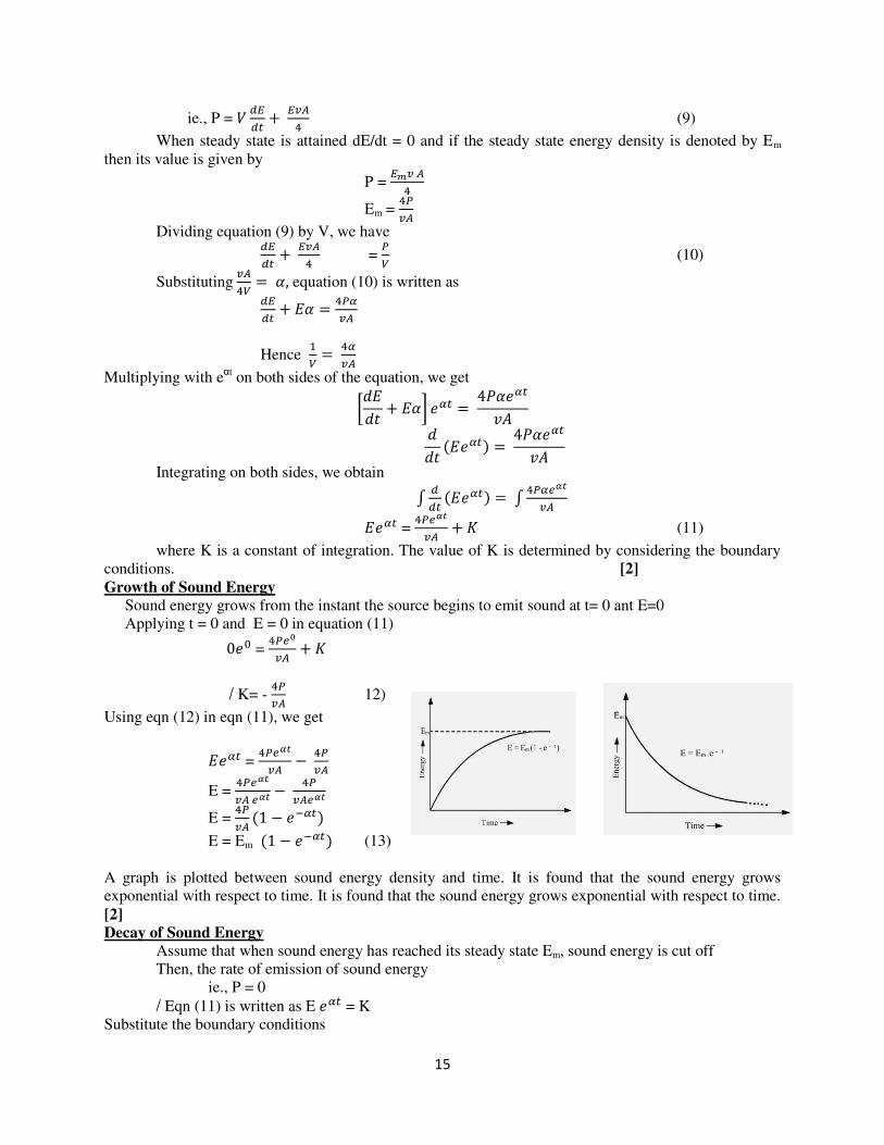
E = Em (13)
A graph is plotted between sound energy density and time. It is found that the sound energy grows
exponential with respect to time. It is found that the sound energy grows exponential with respect to time.
Decay of Sound Energy Assume that when sound energy has reached its steady state Em, sound energy is cut off Then, the rate of emission of sound energy
ie., P = 0
/ Eqn (11) is written as E = K Substitute the boundary conditions
E = Em at t = 0 and P = 0 in equations (11), we get
Em
K = Em (14)
From eqns (11) and (14), we get
E = Em
E = Em (15)
The above equation represents the decay of sound energy density with time after the source is cut off. A
graph is plotted between sound energy density and time. It is an exponentially decreasing curve as shown
in fig. Also, it is found that during the decay sound energy decays exponential with respect to time.
Expression for Reverberation Time. We know that standard reverberation time T is the time taken by the sound to fall of its intensity
to one-millionth of its initial value after the source is cut off.
Now the sound energy density before cut off is Em. At standard reverberation time, it reduces to E = Em/10
6
/ E = Em10-6
We put E = Em10-6 and t = T in eqn(15)
Em10-6 = Em
10-6 =
/ = 106 Taking log on both sides, we have
αT = 6
αT = 6 x 2.3026 x
T =
Substituting
, we get

T =
T =
Taking v =330 m/s
We have, T =
T =
Or T =
∑
This equation is in good agreement with the experimental values obtained by sabine. This is sabine’s formula for
reverberation time.
i) Directly proportional to the volume of the auditorium
ii) Inversely proportional to the areas of sound absorbing surfaces such as ceiling wall floor
and other materials present inside the hall and
iii) Inversely proportional to the total absorption
15.a Explain the modes of vibrations of CO2 molecule. Describe the construction and working of CO2 laser with necessary diagrams. (16)
Vibrational modes of Co2
1. Symmetric stretching mode: Carbon is at rest and Oxygen vibrates along the axis of the molecule.
2. Bending mode: Atoms will perpendicular to the molecular axis.
3. Asymmetric stretching mode: Here all the three atoms will vibrate.
Principle
Laser transition takes place between the vibrational energy states of
Co2 molecules.
Construction and working
It consists of a quartz discharge tube 5 m long and 2.5 cm in
diameter. This discharge tube is filled with the gas mixture of Co2, nitrogen and helium with suitable partial pressures. The ends of the tube
are fitted with NaCl windows.
1. Electron impact excites vibrational motion of the nitrogen. 2. Collisional energy transfer between the nitrogen and the carbon dioxide molecule causes
vibrational excitation of the carbon dioxide
3. The nitrogen molecules are left in a lower excited state. Their transition to ground state
takes place by collision with cold helium atoms.
4. For CO2 laser the main transition is at a wavelength of 10.6 μm and 9.6 μm.
Advantages: Output is continuous, high efficiency, high output power
Disadvantages: Corrosion may takes place, contamination of oxygen by carbon monoxide
Applications: Remote sensing, neurosurgery, general surgery, bloodless operations
15.b Classify the optical fibres on the basis of materials, modes of propagation and refractive
index difference. (16)
Based on material
Based on material it can be classified as glass and plastic fibre. The glass fibres are made up of mixed metal oxides with silicon dioxide.
1. Glass /glass fibres (glass core with glass cladding)
2. Plastic/plastic fibres (plastic core with plastic cladding)
Based on modes
Single mode fibre
If only one light mode is transmitted
It has a small core diameter of the order of 5 – 10 μm.
Advantages: No intermodal dispersion takes place.
Multimode fibre
Light signal is transmitted in more than one light modes
It has large core diameter of the order of 125 – 200 μm.
Disadvantages: Intermodal dispersion takes place
Based on refractive index
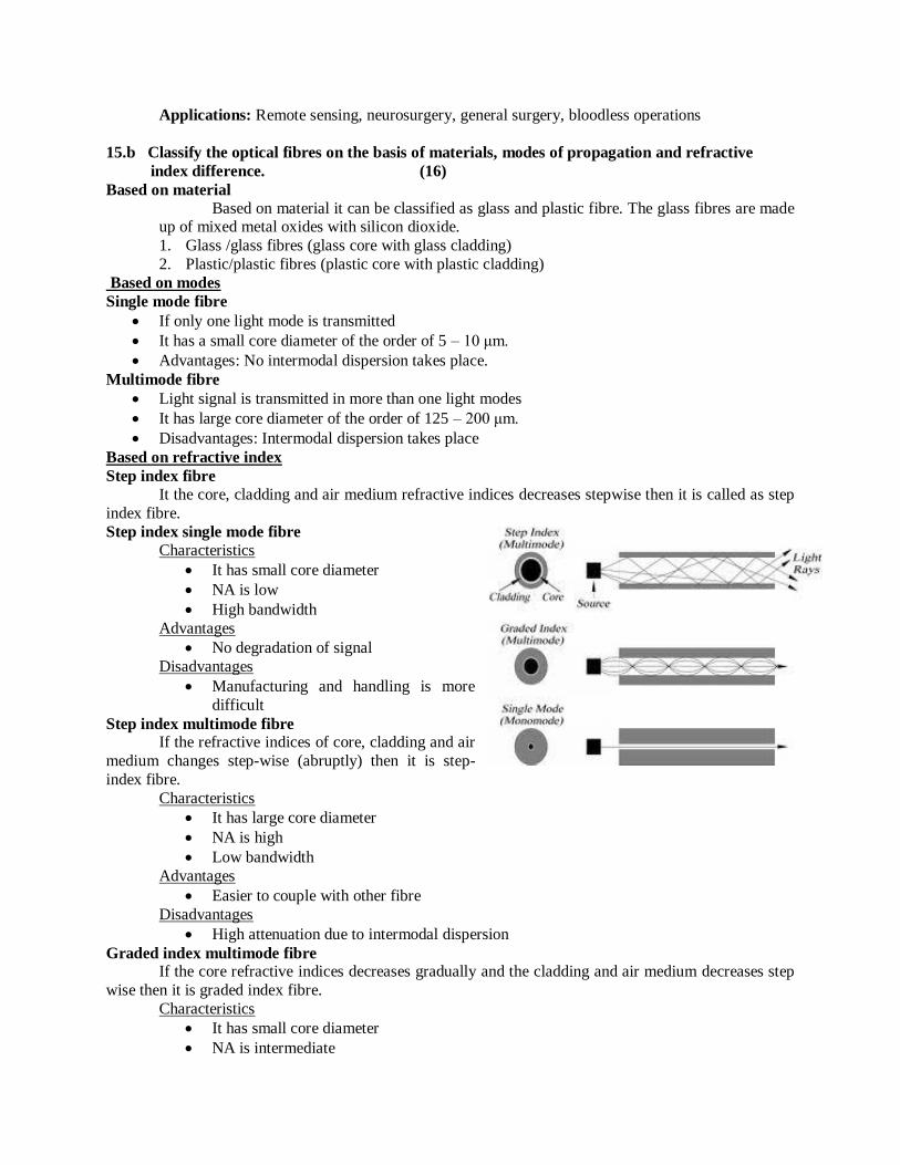
Step index fibre
It the core, cladding and air medium refractive indices decreases stepwise then it is called as step
index fibre.
Step index single mode fibre Characteristics
It has small core diameter
NA is low
High bandwidth
Advantages
No degradation of signal
Disadvantages
Manufacturing and handling is more
difficult
Step index multimode fibre If the refractive indices of core, cladding and air
medium changes step-wise (abruptly) then it is step-
index fibre.
Characteristics
It has large core diameter
NA is high
Low bandwidth
Advantages
Easier to couple with other fibre
Disadvantages
High attenuation due to intermodal dispersion
Graded index multimode fibre If the core refractive indices decreases gradually and the cladding and air medium decreases step
wise then it is graded index fibre.
Characteristics
It has small core diameter
NA is intermediate
Advantages
Intermodal dispersion can be minimized
Disadvantages
Manufacture graded index fibre is more complex.


1
ST. JOSEPH’S COLLEGE OF ENGINEERING
ST.JOSEPH’S INSTITUTE OF TECHNOLOGY
GENERAL MODEL III – DECEMBER 2015
ANSWER KEY [SET- II]
Part A
1. What is Epitaxial growth? The process of growing an oriented single crystal layer on a substrate wafer is called epitaxial
growth.
2. What is melt growth? Melt growth is a process of crystallization by fusion and resolidification of the starting
materials.
3. State Newto ’s la of ooli g.
It states that the rate at which a body loses heat is directly proportional to the temperature
difference between the body and that of the surroundings. The amount of heat radiated depends upon
the area and nature of the radiating surface.
4. Define neutral surface and neutral axis.
In the middle of the beam, there is a layer which is not elongated or compressed due to bending of
the beam, this layer is called neutral surface and the line at which the neutral layer intersects the plane of
bending is called the neutral axis.
5. What are matter waves? The waves associated with the particles of matter (electrons, photons) are known as matter
waves.
6. Cal ulate the o. of photo s e itted a atts sodiu apor la p. Gi e λ = 5893Å.
hc
E
10
834
105893
10310625.6
= 3.3726 x 10⁻¹⁹
J
N = Power / Energy
19103726.3
100
= 2.2965 x 10 20
per second
7. What are the characteristics of musical sound?
There are 3 characteristics for a musical sound, they are
(i) Pitch or Frequency
(ii) Quality or Timber
2
(iii) Intensity or Loudness
8. Mention the properties of ultrasonics.
i. They are highly energetic.
ii. They are nothing but acoustical waves.
iii. They show negligible diffraction due to their small wavelength
9. What are the difference between spontaneous emission and stimulated emission?
Spontaneous emission Stimulated emission
Emission of light is caused without any
external influence
Induced emissions of light caused by incident
photons
Emitted photon travels in random
direction
Emitted photons can be made to travel in
particular direction
Emitted photons cannot be controlled Emitted photons can be controlled
10. Find the wavelength of emitted photons from a GaAs laser diode, which has a bandgap of 1.44eV.
= ℎ�� = Å ̇
PART – B
11.a. i) What are Miller Indices? Explain how they are determined with any two planes in SC
structure. Give their significance.
Miller indices are defined as the three smallest possible integers which have the same ratio as
the reciprocals of the intercepts of the plane concerned along the three axes. (2)
Steps to determine the Miller indices (2)
(i) Find the intercepts
(ii) Take the reciprocals of intercepts.
(iii) Reduce the numbers to three smallest integers
.This last set is enclosed in parentheses (h k l), is called the index of the plane or Miller Indices.
Diagram (2)
3
Significance of Miller indices (2)
Parallel planes have the same Miller indices.
If a plane is parallel to any one of the coordinate axis, then its intercept will be at infinity and the
Miller index for that particular axis is zero
ii. Sho that for a u i latti e, the dista e et ee t o su essi e pla es h k l is gi e d= a/√ (h2+k2+l2).
Let us consider a cubic crystal with a as length of the cube edge and a plane ABC as shown in
figure. The perpendicular OD from the origin of the cube to the plane ABC represents interplanar
spacing (d). The plane ABC makes OA, OB and OC as intercepts on the reference axes, OX, OY and OZ
respectively. , , and are the angles between reference axes OX, OY, OZ and OD. (2)
Diagram (2)
OA : OB : OC = 1/h : 1/k : 1/l = a/h : a/k : a/l
Therefore, OA = a/h: OB = a/k and OC = a/l
From the geometry of right angles, OAD, OBD and OCD,
we have
Cos = OD/OA = d/(a/h) = dh/a
Similarly, Cos = OD/OB = dk/a and Cos = OD/OC = dl/a
According to the law of direction cosines
Cos 2 +Cos
2 + Cos 2 = 1
Substituting the values, (dh/a)2 + (dk/a)
2 + (dl/a)
2 = 1
d2(h
2 + k
2 + l
2) = a
2

4
or
= �√ℎ + + (4)
11.b. Describe the structure of Diamond
It consists of two interpenetrating FCC lattices, displaced along the body diagonal of the cubic
cell by ¼th
of the length of the diagonal. (2)
No of atoms per unit cell
Each corner atom is shared by 8 adjacent unit cells; therefore the contribution of the corner
atoms is 1. The contribution of each face centered atom to the unit cell is ½. Therefore there are totally
3 face centered atoms in each unit cell. Four atoms are present inside the unit cells. Hence the total
number of atoms in the unit cell is 3 + 1 + 4 = 8. (2)
Atomic radius
Diagram (2)
Both the face centered atoms and the corner atoms are in contact with the four central atoms.
From figure, the nearest neighbours in direct contact are X and Y.
(XY)2 = (XZ)
2 + (ZY)
2
(XY)2 = [(XT)
2 + (TZ)
2] + (ZY)
2 = 3a
2/16 = 4r
2
Ato i adius, = a√ /8 (4)
Coordination number
The number of nearest atoms for the central atom is 4. Therefore, the coordination number for
diamond is 4. (2)
Atomic packing factor
APF = Volume occupied by the atoms per unit cell (v) / Volume of the unit cell (V)
A.P.F = × �� =
√ � = 0.34 (4)

5
12.a. Define the coefficient of thermal conductivity and deduce the mathematical expression for
thermal conduction in a compound medium.
HEAT CONDUCTION THROUGH A COMPOUND MEDIA (SERIES AND PARALLEL) (8)
Consider a composite slab of two different materials, A & B of thermal conductivity K1 & K2
respectively. Let the thickness of these two layers A & B be d1 and d2 respectively
Let the temperature of the end faces be θ1 & θ2 and temperature at the contact surface be θ, which
is unknown. Heat will flow from A to B through the surface of contact only if θ1 > θ2. After steady state is
reached heat flowing per second (Q) through every layer is same. A is the area of cross section of both
layers
Amount of heat flowing per sec through A Q = � � � − � / (1)
Amount of heat flowing per sec through B Q = � � � − � / (2)
Since the amount of heat flowing through A and B are equal,
Equation (1) = Equation (2) � � � − � / = � � � − � /
Rearranging and we get,
/ θ =
� �� + � ��� � +� � (3)
By substituting the values of θ in eqn (1), we get,
Q =
� � � −� �� + � ��� � +� �
finally we get,

6
Q = � � − ��� + �� (4)
The above equation gives the amount of heat conducted by two layers in series.
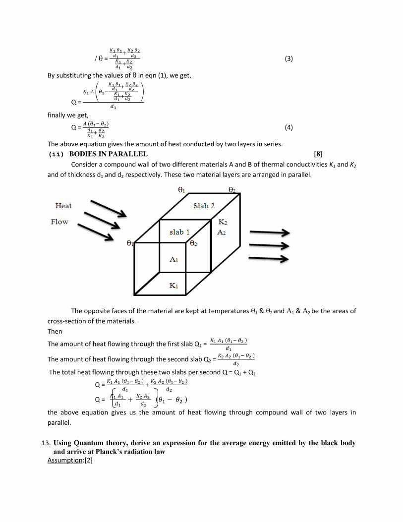
(ii) BODIES IN PARALLEL (8)
Consider a compound wall of two different materials A and B of thermal conductivities K1 and K2
and of thickness d1 and d2 respectively. These two material layers are arranged in parallel.
The opposite faces of the material are kept at temperatures θ1 & θ2 and A1 & A2 be the areas of
cross-section of the materials.
Then
The amount of heat flowing through the first slab Q1 = � � � − �
The amount of heat flowing through the second slab Q2 = � � � − �
The total heat flowing through these two slabs per second Q = Q1 + Q2
Q = � � � − �
+ � � � − �
Q = � � + � � � − �
the above equation gives us the amount of heat flowing through compound wall of two layers in
parallel.
12.b. Derive an expression for the elevation at the centre of a beam which is loaded at both ends.
Des ri e a e peri e t to deter i e You g’s odulus of a ea u ifor e di g.

7
• The beam is loaded uniformly on its both ends; the bent beam forms an arc of a circle. An
elevation in the beam is produced. This bending is
called uniform bending. (2)
Description (4)
Diagram (4)
• Consider a beam (or bar) AB arranged horizontally on
two knife – edges C and D symmetrically so that AC =
BD = a as shown in Figure.
• The beam is loaded with equal weights W and W at the ends A and B.
• The reactions on the knife edges at C and D are equal to W and W acting vertical upwards.
Derivation (6)
• The external bending moment on the part AF of the beam is
= W x AF – W x CF = W (AF – CF)
= W x AC = W x a
• Internal bending moment is given by = R
YI g
where Y - Young’s modulus of the material of the bar, Ig - Geometrical moment of inertia of the
cross-section of beam, R - Radius of curvature of the bar at F.
• In the equilibrium position, external bending moment = internal bending moment
R
YIWa
g
2
8
R
1
l
y
Wa = g2I
8Y
y
yI
alWY
g8
2
13.a.Draw a neat diagram and explain the working of Transmission electron Microscope.
Transmission electron microscope
Principle: (2)
electrons are made to pass through the specimen
Image is formed on fluorescent screen(bright field image) or by diffracted beam(dark field image)
Construction (4)
It consists of electron gun to produce electron
Magnetic condensing lens are used to condense electron and adjust the size of electron that falls
on the specimen

8
Diagram: (6)
The specimen is placed in between condensing lens and objective lens
Magnetic objective lens is used to block high angle diffracted beams and aperture is used to
eliminate diffracted beams
This increases the contrast of the image
Magnetic Projector lens is placed above the fluorescent screen to achieve higher magnification
Image can be recorded by fluorescent(phosphor)screen or CCD (charged coupled device)
Working (4)
Electron gun produces electron
Falls on specimen by magnetic condensing lens
Based on angle of incidence, beam is partly transmitted and partly diffracted
Both the transmitted and diffracted beams are recombined at Ewalds sphere(sphere enclosing all
possible reflections from crystal satisfying brag’s law) To increase the intensity and amplitude contrast image has to be obtained
Can be achieved only by using transmitted beam
The diffracted beam has to be eliminated
To eliminate diffracted beam ,resultant is passed through projector lens for further magnification
Magnified image is recorded on CCD
High contrast image is called bright field image
Advantages
Used to examine specimen up to 0.2 nm
Disadvantages
Specimen should be thin
Applications
Used to find internal structures in Nanoscience

9
13.b. Using Schrodinger’s time independent wave equation normalize the wave functions of electron trapped in a one dimensional potential well.
PARTICLE IN A 1D POTENTIAL BOX:
Consider a e-
with mass m moving along x axis enclosed in 1D box.
As walls are of infinite potential, particle cannot possible.
Length of box : l
Outside on the wall : v = α
Inside the wall: v = 0
Boundary conditions:
V(x) = 0, 0 < x < l
V x = α , ≥ x ≥ l
O e di e sio al s h oedi ge ’s a e e uatio :
� � + ℏ � − � � =
For a free particle, V = 0
� � + ℏ � � = 0
� � + � � = 0 ----------------- 1 (4)
Solution to 1:
Ψ x = A si kx + os kx ------------------- 2
Applying boundary conditions:
I. At x=0; v=α
Pa ti le a ot exist Ψ=
Eqn 3 becomes
0= A sin0 + B cos0
B=0
II. At x=l, v= α (Ψ=0) A sinkl =0
A not equal to zero then sinkl=0
Kl = nπ (or) k = �

10
Ψ x = A si �� (4)
ENERGY OF THE PARTICLE
From, K2 =
�ℏ
n2π2
= � �ℎ
(OR) � = ℎ
For each n – energy level and wave function
En = eigen value a d Ψn = eigen function
Energy levels of an e- :
n = 1 is the lowest energy � = ℎ � = ℎ � = ℎ
E2 = 4E1
General � = �
Energy levels are discrete – big success of quantum theory. (4)
NORMALISATION OF WAVE FUNCTION:
Process by which probability (P) of finding the particle inside the box can be done.
For a 1D box,
P = ∫ |�| � =l
P = ∫ � sin � � � =
(or) A ∫ − os π n xll dx = or � [�] =
A = [ l⁄ ] ⁄
Normalized wave function can be written as
�� = [ l⁄ ] ⁄ sin � � (4)

11
14.a.i) what is sonogram? how do you analyse the internal parts of the body.
SONOGRAM:
It is a device to view the fetus and it helps to record its movement
This device also helps in viewing internal organs which are invisible to human eye
Principle(2)
1. This device works with the principle of Doppler effect
2. There is an apparent change in frequency between the incident radiation falling on the fetus and
the reflected from the fetus
Construction (1)
It consists of radio frequency oscillator producing 2 MHz frequency ultrasonic waves .
The radio amplifier helps in amplifying the received radiations
Mixer is used to mix the transmitted and received signals.
The cro and loud speaker helps in viewing and hearing the output of the sound waves
The block diagram is shown in the figure below
Diagram (3)
Working (2)
The t a sdu e is fixed o othe ’s a do e
Radio frequency oscillator is on and transducer produces 2MHz ultrasonic waves.
These waves are incident on the fetus
The received waves are collected by the transducer and amplified by radio frequency amplifier
The incident and reflected waves are mixed by the mixer and filtered to distinguish various types
of sound waves
The change in frequency or Doppler shift is measured.
The heart beat is heard from the loud speaker and movements are viewed by cro

12
Advantages over other methods:
There are no residual effects
ii) Explain the determination of velocity of ultrasonics using an acoustical grating.
PRINCIPLE (1)
When ultrasonic waves propagate in a liquid medium, the stationary waves are produced.
This will change the density of the liquid and change the refractive index of the liquid
Now the liquid column acts as diffraction grating and hence called as acoustical grating.
If a monochromatic light is passed through liquid, diffraction of liquid takes place.
From the diffraction condition, we can determine the velocity of an ultrasonic waves.
CONSTRUCTION (1)
It consists of a glass tank, filled with the liquid(Kerosene)
A quartz crystal is fixed on the top of the liquid tank
to produce ultrasonic.
‘S’ is the mono chromatic source parallelized by two
lenses L1 and L2
Telescope is used to view the diffraction pattern.
WORKING (1) and diagram (2)
Initially the piezo electric crystal is at rest and the mono chromatic light from the source is passed
through the liquid.
A vertical peak is observed in the telescope, It means that there is no diffraction
Now the oscillatory circuit is switched ON and the crystal starts to vibrate.
So the producing ultrasonic waves create nodes and antinodes in a liquid.
At nodes, density of the liquid is maximum and at antinodes density is minimum.
Hence, liquid behaves as a acoustical grating.
Now, if the light is made to pass through the liquid it will get diffracted.
The diffraction pattern consists of one peak as central maxima (� and two peak as principal
maxima (� on either side.

13
CALCULATION OF VELOCITY (3) Bragg’s diffraction condition is, n� = 2d ��� � (1)
d = distance between successive nodes (or) anti nodes � = angle of diffraction
n = order of spectrum � = wavelength of the mono chromatic source of light
If the wavelength of ultrasonic wave is �u = 2d (2)
Then equation (1) becomes �� ��� � = ��
�� = ������ (3)
We know that
Velocity of ultrasonics = frequency of ultrasonics wavelength of ultrasonics �� = ���� (4)
Substitute (3) in (4)
�� = ��������
Thus the velocity (or) wavelength of the ultrasonics can be determined using acoustical grating.
14.b. State a d e plai Sa i e’s for ula for re er eratio ti e of a hall. Deri e Sa i e’s for ula for
reverberation time
The relation connecting the reverberation time with the volume of the hall, the area and absorption
oeffi ie t is k o as sa i e’s fo ula.
Let us consider a small element 'ds' on a plane wall AB.
surface area of this element =rdθdr (1)
This surface element is rotated about the normal through an angle dФ and the circumferential distance moved by this element is r sinθdФ.
Volume traced out by this area element = area of the element x distance moved

14
dV=rdθdr(r sin θ dФ) =r
2 sin θdθdrdФ (2)
If E is the sound energy density i.e. energy per unit volume
Then energy present in the volume =EdV. (3)
Since the sound energy from this volume element propagates in all directions (i.e. through solid angle 4π) The energy traveling per unit solid angle =
E Vπ (4)
The energy traveling towards surface element ds alone falls on ds.
The solid angle subtended by area ds at this element of volume dV = s osθ
Hence energy traveled towards ds from the Volume element dV = � � ��
= � � � � � ��
= � � � � � � � (5)
total sound energy falling on ds per second
= � � ∫ � � � �� ∫ �� ∫�
= ��
(6)
If α is the absorption coefficient of the wall AB of which ds is a part, then sound energy absorbed
by ds in one second = �� �
/ Total sound energy absorbed per second by the whole enclosure = �� ∑ �
= ���
(7) [8]
Where A = Σαds is total absorption of sound in all the surfaces inside the hall on which sound
energy is incident.
Growth and Decay of sound energy
If P is sound power output, i.e., rate of emission of sound energy from the source and V is the
total volume of the hall, then
Total sound energy in the hall at a given instant ‘t’ = EV
/ Rate of growth of sound energy = �� = � � (8)
Rate of emission of sound energy by the source = Rate of growth of sound energy in the room + Rate of
Absorption of sound energy by the walls
15
ie., P = � � + ��� (9)
When steady state is attained dE/dt = 0 and if the steady state energy density is denoted by Em
then its value is given by
P = � � �
Em = ���
Dividing equation (9) by V, we have
� + ���
= �� (10)
Substituting ��� = �, equation (10) is written as
� + �� = ����
Hence � = ���
Multiplying with eαt
on both sides of the equation, we get [ � + ��] � = 4�� ��� � � = 4�� ���
Integrating on both sides, we obtain
∫ � � = ∫ �� ����
� � = � ���� + � (11)
where K is a constant of integration. The value of K is determined by considering the boundary
conditions. [2]
Growth of Sound Energy Sound energy grows from the instant the source begins to emit sound at t= 0 ant E=0
Applying t = 0 and E = 0 in equation (11) = ��� + �
/ K= - ��� 12)
Using eqn (12) in eqn (11), we get
� � = � ���� − ���
E = � ���� �� − ��� ��
E = ��� − −�
E = Em − −� (13)
A graph is plotted between sound energy density and time. It is found that the sound energy grows
exponential with respect to time. It is found that the sound energy grows exponential with respect to time.
[2]
Decay of Sound Energy Assume that when sound energy has reached its steady state Em, sound energy is cut off
Then, the rate of emission of sound energy
ie., P = 0
/ Eqn (11) is written as E � = K
Substitute the boundary conditions

16
E = Em at t = 0 and P = 0 in equations (11), we get
K = Em (14)
From eqns (11) and (14), we get
E � = Em
E = Em −� (15)
The above equation represents the decay of sound energy density with time after the source is cut
off. A graph is plotted between sound energy density and time. It is an exponentially decreasing curve as
shown in fig. Also, it is found that during the decay sound energy decays exponential with respect to time.
[2]
Expression for Reverberation Time. We know that standard reverberation time T is the time taken by the sound to fall of its intensity
to one-millionth of its initial value after the source is cut off.
Now the sound energy density before cut off is Em. At standard reverberation time, it reduces to
/ E = Em10-6
We put E = Em10-6
and t = T in eqn(15)
/ �� = 106
Taking log on both sides, we have
log �� = log
αT = 6 x 2.3026 x log
T = × . × �
Substituting � = ��� , we get
T = × . × ���
T = × . × �vA
Taking v =330 m/s
We have, T = × . × � × A
T = . �A
Or T = . �∑ �
This is sa i e’s formula for reverberation time. [2]
15.a. . Deri e Ei stei ’s relatio for sti ulated e issio a d he e e plai the e iste e of stimulated emission.

17
Let N1 be the number of atoms per unit volume in the ground state E1 and these atoms exist in the
radiation field of photons of energy E2-E1 =h v. The rate of absorption R1 (E1 to E2) is proportional to the
number of atoms N1 per unit volume in the ground state and proportional to the energy density E of
radiations.
R1 = B12N1 E ------ (1)
where B12 is known as the Einstein’s coefficient of stimulated absorption.
The rate R2 of spontaneous emission E2-> E1 is independent of energy density E of the radiation
field. R2 is proportional to number of atoms N2 in the excited state E2 thus
R2=A21 N2 ------ (2)
where A21 is known as Einstein’s coefficient for spontaneous emission.
The rate R3 for stimulated emission E2-> E1 is proportional to energy density E of the radiation
field and proportional to the number of atoms N2 in the excited state, thus
R3=B21N2 E ------ (3)
where B21 is known as the Einstein coefficient for stimulated emission. In steady state (at thermal
equilibrium), R1=R2+R3 [8]
Using equations (1, 2, and 3), we get
E =A21/B21 {1/N1/N2(B12/B21-1)}
Einstein proved thermodynamically, that the probability of stimulated absorption is equal to the
probability of stimulated emission. Thus
B12=B21… therefore, E=A21/B21(1/N1/N2-1)
Substituting value of N1/N2, we get
E= A21/B21(1/ehv/KT
-1)
Now according to Planck’s radiation law, the energy density of the black body radiation of frequency v at temperature T is given as
E = 8πhv3/c
3(1/e
hv/KT)
By comparing equations (6 and 7), we get
A21/B21=8πhv3/c
3
This is the relation between Einstein’s coefficients in laser. [8]
15.b. Classify the optical fibres on the basis of materials, modes of propagation and refractive index
difference
Based on materials [2]
i) glass
ii) fibre
Based on modes [7]
Single mode fibre
If only one light mode is transmitted
It has a small core diameter of the order of 5 – μ . Advantages: No intermodal dispersion takes place.
Multimode fibre
Light signal is transmitted in more than one light modes
It has large core diameter of the order of 125 – μ . Disadvantages: Intermodal dispersion takes place
Based on refractive index [7]
Step index fibre

18
It the core, cladding and air medium refractive indices decreases stepwise then it is called as
step index fibre.
Step index single mode fibre
Characteristics
It has small core diameter
NA is low
High bandwidth
Advantages
No degradation of signal
Disadvantages
Manufacturing and handling is more difficult
Step index multimode fibre
If the refractive indices of core, cladding and air medium changes step-wise (abruptly) then it is
step-index fibre.
Characteristics
It has large core diameter
NA is high
Low bandwidth
Advantages
Easier to couple with other fibre
Disadvantages
High attenuation due to intermodal
dispersion
Graded index multimode fibre
If the core refractive indices decreases gradually and the cladding and air medium decreases
step wise then it is graded index fibre.
Characteristics
It has small core diameter
NA is intermediate
Advantages
Intermodal dispersion can be minimized
Disadvantages
Manufacture graded index fibre is more complex.

REGNO :
St. JOSEPH'S COLLEGE OF ENGINEERING
St. JOSEPH'S INSTITUTE OF TECHNOLOGY
SPECIAL MODEL EXAM III - December 2015
Subject : ENGINEERING PHYSICS-I Code : PH6151
Branch : Common to B.E/B.TECH Sem : I
DURATION : 3 hours MAX MARKS: 100
PART - A (10 X 2 = 20 Marks)
1. What is meant by primitive and non- primitive cell? Give examples
2. Bismuth has a=b=c =4.74 Å and angles α = β = γ = 60o . What is its crystal structure?
3. Define Poisson’s ratio.
4. Define yield point, tensile strength and breaking point.
5. Define resolving power and depth of focus.
6. What is a photon? Write its properties.
7. State Weber –Fechner law.
8. Write down the medical applications of ultrasonics.
9. Write the differences between spontaneous emission & stimulated emission.
10. Find the wavelength of emitted photons from a GaAs laser diode, which has a
bandgap of 1.44eV.
PART - B (5 X 16 = 80 Marks)
11 Define the terms atomic radius and packing factor. Calculate the above for SC, BCC
and FCC structures.
(16)
12. Describe with relevant theory the method of determining the coefficient of thermal
conductivity of a bad conductor by Lee’s method.
(16)
13. Derive time independent Schrödinger wave equation and hence deduce time
dependent Schrödinger wave equation.
(16)
14. Explain piezo-electric effect. Describe the piezo-electric method of producing
ultrasonic waves. (4)
(16)
15. i) Describe the principle, construction, working and energy level diagram of
semiconductor laser. (12)
ii) In InP Laser diode, the wavelength of light emission is 1.55 μm. What is its band
gap in eV? (4)
(16)

St. JOSEPH'S COLLEGE OF ENGINEERING
St. JOSEPH'S INSTITUTE OF TECHNOLOGY
SPECIAL MODEL - III
Subject: ENGINEERING PHYSICS-I Code: PH6151
Branch: Common to B.E/B.TECH Sem : I
DURATION: 3 hours MAX MARKS: 100
PART - A (10 X 2 = 20 Marks)
1) What is meant by primitive and non- primitive cell? Give examples.
Primitive cell consists of only one atom per unit cell, while non-primitive cell consists of
more than one unit cell.
2) Bismuth has a=b=c =4.74 Å and angles α = β = γ = 60o . What is its crystal structure?
Trigonal or Rhombohedral.
3) Define Poisson’s ratio. The ratio of Lateral strain (β) to the Linear strain (α) is called as Poisson’s ratio.
Poisson ratio
4) Define yield point, tensile strength and breaking point. The point at which the body loses its elasticity due to the addition of heavy load is called
yield point.
The point at which applied stress exceeds the tensile strength, which makes the wire to break
down completely is called Breaking point.
The maximum force to which the wire is subjected divided by its original cross-sectional area
is called as Tensile strength.
5) Define resolving power and depth of focus.
Resolving power is the ability of an optical instrument to form a distinct and separable
image of the two point objects which are close to each other.
Depth of focus is the ability of the objective of microscope to produce a sharp focused
image when the surface of the object is not truly plane.

6) What is a photon? Write its properties.
i.Photons are discrete energy values in the form of small quanta of definite frequency (or)
wavelength.
ii. They do not have any charge and they will not ionize gases.
iii. The energy and momentum of the photon is given by E = h ν and p= mc
7) State Weber –Fechner law.
Loudness of sound is defined as the degree of sensation produced on the ear. This cannot be
measured directly. So that it is measured in terms of intensity. Loudness is proportional to
logarithmic value of intensity.
L ∞ log I ; L = K log I ; This is also known as Weber-Fechner’s Law
8) Write down the medical applications of ultrasonics. Diagnostic Applications: Ultrasonics are used for detecting tumors and other defects in
human body.
Surgical Applications: They are used to remove kidney stones and brain tumors without loss of any blood.
9) Write the differences between spontaneous emission & stimulated emission.
Spontaneous emission Stimulated emission
Emission of light is caused without
any external influence
Induced emissions of light caused by incident
photons
Emitted photon travels in random
direction
Emitted photons can be made to travel in
particular direction
Emitted photons cannot be controlled Emitted photons can be controlled
10) Find the wavelength of emitted photons from a GaAs laser diode, which has a bandgap
of 1.44eV.
Ans: = 8626 А

PART - B (5 X 16 = 80 Marks)
11) Define the terms atomic radius and packing factor. Calculate the above for SC, BCC and FCC structures. (16) Lattice parameters
The intercepts a, b, c of a unit cell and the interfacial angles α, β
and γ along the three axes are called the lattice parameters.
Atomic radius
It is defined as half of the distance between two nearest neighbours in a crystal of a pure
element.
Packing Factor
It is defined as the ratio of the volume of atoms per unit cell to the total volume occupied by
the unit cell.
APF = No of atoms present in the unit cell x volume of one atom
Volume of the unit cell
Simple Cubic structure: SC
Atomic radius
In a Simple Cubic structure the corner atoms touch each other along the edges as shown in
fig. Let us consider one face (front face) of the structure
Here the nearest neighbour distance is the lattice constant a = 2r
∴ r = a/2
Packing factor
Let ‘a’ be the edge length of the unit cell and r be the radius of sphere. As the atoms are touching each
other, a = 2r
No. of atoms per unit cell = 1/8 × 8 = 1
Volume of the sphere = 4/3 πr3
Volume of the cube = a3= (2r)3 = 8r3
∴ Fraction of the space occupied = 1/3πr3 / 8r3 = 0.524
∴ % occupied = 52.4 %

Body Centered Cubic System: BCC
Atomic radius
In BCC, the corner atoms do not touch each other. But each corner atom touches the body
centered atom along the body diagonal as shown. From the geometry of the fig, we can write
(AD)2 = (AC)2 + (CD)2
AD = a√3
The diagonal of the cube= AD = 4r
4r = a√3
∴ r= a√3/4
Packing Factor
A.P.F = = = 0.68
Face centered cubic structure: FCC
Atomic radius
Three atoms are in contact along the face diagonal. Therefore,
r + 2r + r = 4r
From geometry of the unit cell, the face diagonal of a cube of side ‘a’ is a√2.
Equating, 4r = a√2
Atomic radius r = a√2/ 4.
Packing factor for FCC
A.P.F = = = 0.74.
12. Describe with relevant theory the method of determining the coefficient of thermal conductivity of a bad conductor by Lee’s method. (16)
The apparatus consists of a circular metal disc of slab C (lee’s disc) suspended by strings from a
stand. The given bad conductor is taken in the form of a disc (D). A cylindrical hollow steam chamber (A) having the same diameter as that of the slab is placed over
the bad conductor. There are holes in the steam chamber and the slab through which thermometers
T1 and T2 are instead to record the respective temperatures.

Working:
Steam is passed through the steam chamber until the temperatures of the chamber and the slab
are steady. When the thermometers show steady temperatures, their reading θ1 and θ2 are noted. The radius of the disc and its thickness are also noted.
Observation and calculation:
M - Mass of the disc 10-3
(Kg)
S - Specific heat capacity of the slab (J/kg/K)
d - Mean thickness of bad conductor (m)
r - Mean radius of the bad conductor (m)
1 - Steady temperature in the slab (K)
2 - Steady temperature of the bad conductor (K)
R - Rate of cooling at 2 (K/sec).
Area of the cross section (m2)
Amount of heat conducted through the specimen per second
Q = = (1)
At this stage all the heat conducted through the bad conductor is completely radiated by the
bottom flat surface and the curved surface of the slab C.
Amount of heat lost per second by the slab C
Q = Mass x Specific heat capacity x Rate of cooling
At steady rate,
Heat conducted through bad conductor /sec = Heat lost per sec by the slab C
= MSR
/ K= Wm-1k-1 (2)
Thus thermal conductivity of bad conductor is determined.
Determination of rate of cooling
During the first part of the experiment, the top surface of the slab is covered by the bad
conductor. Radiation is taking place only from the bottom surface area and curved surface area.
i.e., total area of =
In the second part of the experiment, heat is radiated from the top surface area, the bottom
surface area and the curved sides. i.e., over an area.
2πr2+ 2πrh = 2πr (r + h)

As the rate of cooling is directly proportional to the surfaces are exposed
R= (4)
Substituting this value in eqn(3), we have
KmWrh
rh
r
dtdMSdK //
22
2
)(
)/(
21
2
2
From which K is determined.
13. Derive time independent Schrödinger wave equation and hence deduce time dependent Schrödinger wave equation. (16)
SCHROEDINGER TIME INDEPENDANT WAVE EQUATION:
Ψ = Ae-i/h (Et-px)
(or) Ψ = ------------------ (1a)
Can be represented as,
Ψ = A Ψ’ ---------- (1) [Ψ’- time independent factor]
Diff (1) w.r.t ‘t’
= A Ψ’ ------------------------ (2)
Diff (1) w.r.t’x’
= A
= A ------------------------ (3)
Schroedinger time dep. wave equ. :
ih = V - ------------------------- (4)
Sub (1), (2) & (3) in (4)

(or)
------------- 5
Taking just symbols
equation 5 is ID schroedinger time independent wave equation.
Writing in 3D,
---------------- 6
The above equation is time independent Schrodinger wave equation.
(i) Time Dependent:
- Particle behaves like wave only when it moves.
-To move, it has to be accelerated by a potential field.
Total Energy E = K.E + P.E
E = V + ½ mv2
E = V + ½ => E = V +
Operating on wave function,
E ψ = V ψ + ψ ---------------(1)
According to classical mechanics, displacement is
Y =
lllly in quantum mechanics,
ψ(x,y,z,t) = position
ψ(x,y,z,t) = ------------------------(2)
=2π
(2) Becomes

Ψ = ------------------------(3)
E = h (or) and
(4) Becomes,
ψ = Ae-2πi
( )
By de-Broglie hypothesis,
=
ψ = Ae-2πi
( )
h = => ψ = Ae-i/h (Et-px)
--------------------------(5)
Diff (5) w.r.t. x
= Ae-i/h (Et-px)
= Ae-i/h (Et-px)
(Or) = ψ
(Or) p2 ψ = - h
2 -------------------(6)
Diff (5) w.r.t time
= Ae-i/h (Et-px)
= E ψ (or) E ψ = i -----------------------(7)
Sub (6) & (7) in (1)
ih =

--------------- (8)
Equ. (8) Represents one dimensional Schrodinger Time Dependant Wave Equation:
Turning (8) to 3D
ih =
= + +
(Or)
Where,
E = ih
H =
14. Explain piezo-electric effect. Describe the piezo-electric method of producing ultrasonic waves. (16)
PIEZO ELECTRIC EFFECT
PIEZO ELECTRIC CRYSTAL
Some crystals are producing piezo-electric effect, so called piezo-electric crystals.
(Eg) -: Quartz, Tourmaline, Rochelle etc.
Quartz has a hexagonal shape with pyramids at the ends. It has 3 axes, viz
(i) X – axis (electrical axis) which joins the corners.
(ii) Y – axis (Mechanical axis) which joins the centre of the sides.
(iii) Z – axis (optic axis) which joins the edges of the pyramid.
X – CUT CRYSTALS
When the crystal cut perpendicular to the X – axis, then t is called X – cut crystal.
It produces longitudinal ultrasonic waves.
X cut X axis Y axis Y cut
E = H

Y – CUT CRYSTALS
When the crystal cut perpendicular to Y – axis, then it is called Y – cut crystal.
It produces transverse ultrasonic waves.
PIEZO – ELECTRIC EFFECT
In the crystal, when the mechanical force applying along mechanical axis (Y – axis), then we will
get electrical force along electrical axis (X – axis) with respect to an optic axis.
INVERSE PIEZO – ELECTRIC EFFECT
In crystal, when we applying the electrical force on
electrical axis(X – axis), then we will get mechanical
force (vibration) from the mechanical axis (Y – axis)
with respect to an optical axis (Z – axis).
PRINCIPLE
Piezo electric generator produces ultrasonic waves by the principle of Inverse piezo
electric effect. At the resonance condition (frequency of the oscillatory circuit is equal to
frequency of the vibrating crystal). The ultrasonics is produced.
CONSTRUCTION
It has two circuits.
(i) Primary, (ii) secondary
PRIMARY CIRCUIT
It consists of some components.
Coil L1 and L2. L1 is connected with base and
L2 is connected with collector of the transistor.
They are inductively connected with coil L2.
Capacitor C1 is used to vary the frequency
of the oscillatory circuit [L1, C]
TRANSISTOR
We should give proper bias to the transistor,
by battery (i.e) Emitter is forward biased and
collector is reverse biased
SECONDARY CIRCUIT
Here coil L3 is connected with the plate A and B.
Place the quartz crystal between the plates A and B.

WORKING
The transistor produces the current with the help of the battery.
That current is passing through the coil L1 and L2.
Due to the transformer action, the current is passing from L1,L2 to L3.
Coil L3 gives current to the plate A and B.
Due to the principle of the inverse of piezo electric effect, the quartz will start to vibrate.
Now we adjust the coil C1 to equalize the frequencies of both oscillatory circuit and quartz
crystal.
If resonance occurs ultrasonic waves will be produced.
15. i) Describe the principle, construction, working and energy level diagram of semiconductor laser. (12)
(i) When p-n junction diode is forward biased, recombination of electrons and holes take
place, which results in the emission of laser light.
Construction and working
The active medium is a p-n junction diode where p and n type materials are made from same
material (gallium arsenide). Optical resonator is provided by polishing the sides of the junction
regions. When p-n junction is forward biased, electrons and holes are injected into junction region.
Now, the electrons and holes recombine with each other with the release of light photons.
When forward biased voltage is increased, more light photons are emitted which triggers a
chain of stimulated recombinations resulting in the emission of laser light at a wavelength of 8300 Å
to 8500 Å. The wavelength of laser light is given by = hc/Eg, where Eg is band gap energy
ii) In InP Laser diode, the wavelength of light emission is 1.55 μm. What is its band gap in eV? (4)
Ans:


ST. JOSEPH’S COLLEGE OF ENGINEERING
ST.JOSEPH’S INSTITUTE OF TECHNOLOGY
SPECIAL MODEL III – DECEMBER 2015
ANSWER KEY [SET- II]
Part A
1. What is graphite structure?
In this graphite structure, carbon atoms are arranged in regular hexagon in flat parallel layers
such that each atom is linked by the neighbouring atoms. However there is no strong bonding between
different layers which are therefore easily separable from each other.
2. Draw the following planes in a cubic structure: (001), (100), (110), (111).
3. Define Hooke’s law.
Within elastic limit, the stress is directly proportional to strain.
Stress α strain;
Stress/ strain = E; where E is called Modulus of elasticity.
4. Define Thermal Diffusivity.
It is defined as the ratio of thermal conductivity to the thermal capacity per unit volume of the
material.Since thermal capacity is the product of specific heat capacity and density of the material.
5. Defi e Wie ’s displa e e t la . give its limitation.
It states that the produ t of the a ele gth (λm) of maximum energy emitted and the absolute
temperature (T) is a constant. λmT = constant. This holds good only for shorter wavelength and not for
longer wavelength
6. give de-Broglie’s a ele gth i ter s of energy, temperature and voltage.
equation?
De-broglie wavelength in terms of energy = mE
h
2
De-broglie wavelength in terms of voltage = mev
h
2
De-broglie wavelength in terms of temperature = mKT
h
3
7. Define absorption coefficient of a material.
The absorption coefficient of a material is defined as the ratio of the sound energy absorbed by
the surface to that of the total sound energy incident on the surface.
Absorption coefficient (a) = Sound energy adsorbed by the surface
Total sound energy incident on the surface
The absorption coefficient can also be defined as the rate of sound energy absorbed by a certain area
of surface to that of an open window of same area.
8. . What is meant by echelon effect?
If there is a regular repetition of echoes of the original sound received by the observer due to the
presence of flight of stairs or set of railings, then the effect is called echelon effect.
9. . Mention the advantages of fiber optic communication system over the conventional systems.
i. Light in weight and small in size.
ii. No possibility of internal noise and cross talk generation
iii. No hazards of short circuits as in metal wires
10. What is the basic principle of fiber sensors?
A fiber sensor consists of a light source. The light source is coupled to an optical fiber. A light
detector receives signal-carrying light beam as it emerges from the fiber. The signal from detector is
processed electrically for getting information.
PART – B
11. Describe the structure of a HCP crystal. Give the details about its atomic radius, co-ordination
number, atomic packing factor and axial ratio.
It consists of three layers.
Upper and lower hexagon wit 6 corner atoms each.
One base centred atom in each hexagon.
Three symmetric atoms. [2]
Atomic radius
The corner atoms touches each other. hence r=a/2. [2]
Co-ordination number
The co-ordination number is 12. [2]
Packing Factor
It is defined as the ratio of the volume of atoms per unit cell to the total volume occupied by the
unit cell.
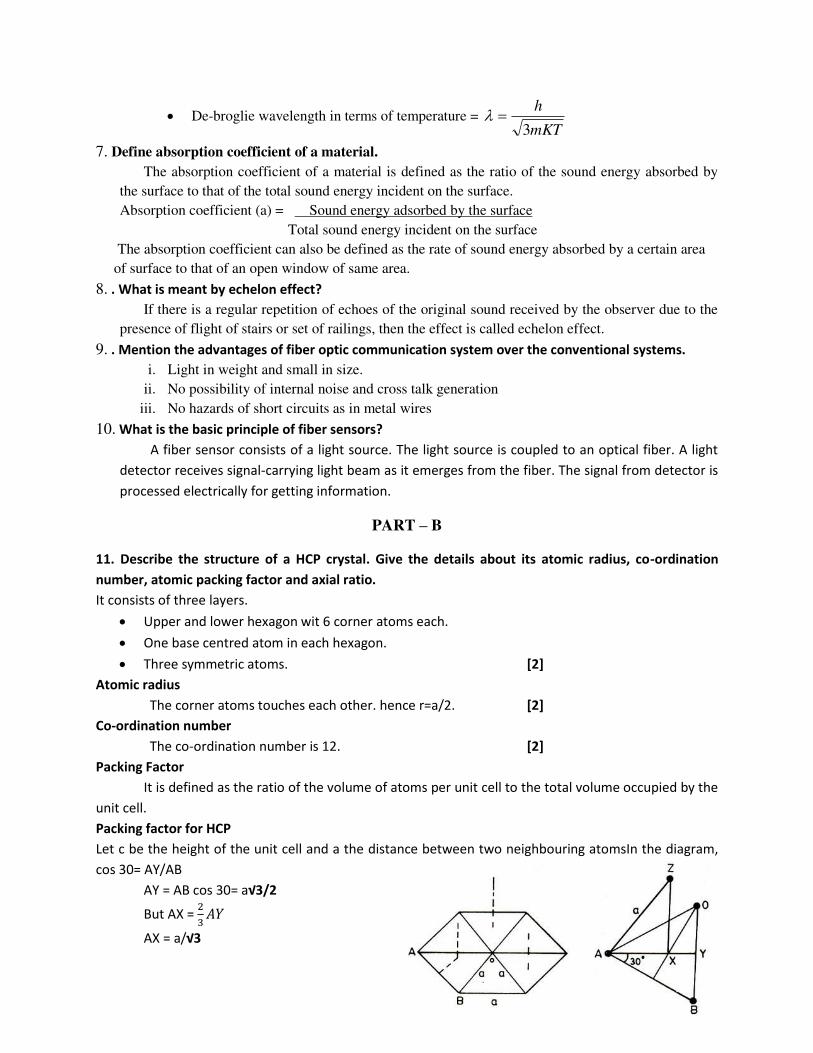
Packing factor for HCP
Let c be the height of the unit cell and a the distance between two neighbouring atomsIn the diagram,
cos 30= AY/AB
AY = AB cos 30= a√ /
But AX = ��
AX = a/√

In triangle AXZ , AZ2
= AX2 + ZX
2 .
a2
= (a/√ )2 + (c/2)
2
Therefore, �� = �
�� = √�
= 1.633 [4]
Packing factor
Volume of all six atoms in the unit cell, v = 6 x �
Atomic radius r = a/2
v = ��
Volume of the unit cell, V= √ �
A.P.F = v/V
= �√ = 0.74 [6]
12. Define the coefficient of thermal conductivity and deduce the mathematical expression for
thermal conduction in a compound medium.
HEAT CONDUCTION THROUGH A COMPOUND MEDIA (SERIES AND PARALLEL) [8]
Consider a composite slab of two different materials, A & B of thermal conductivity K1 & K2
respectively. Let the thickness of these two layers A & B be d1 and d2 respectively
Let the temperature of the end faces be θ1 & θ2 and temperature at the contact surface be θ, which
is unknown. Heat will flow from A to B through the surface of contact only if θ1 > θ2. After steady state is
reached heat flowing per second (Q) through every layer is same. A is the area of cross section of both
layers
Amount of heat flowing per sec through A Q = � � � − � / (1)
Amount of heat flowing per sec through B Q = � � � − � / (2)
Since the amount of heat flowing through A and B are equal,
Equation (1) = Equation (2) � � � − � / = � � � − � /
Rearranging and we get,
/ θ =
� �� + � ��� � +� � (3)
By substituting the values of θ in eqn (1), we get,
Q =
� � � −� �� + � ��� � +� �
finally we get,
Q = � � − ��� + �� (4)
The above equation gives the amount of heat conducted by two layers in series.
(ii) BODIES IN PARALLEL [8]
Consider a compound wall of two different materials A and B of thermal conductivities K1 and K2
and of thickness d1 and d2 respectively. These two material layers are arranged in parallel.
The opposite faces of the material are kept at temperatures θ1 & θ2 and A1 & A2 be the areas of
cross-section of the materials.
Then
The amount of heat flowing through the first slab Q1 = � � � − �
The amount of heat flowing through the second slab Q2 = � � � − �
The total heat flowing through these two slabs per second Q = Q1 + Q2
Q = � � � − �
+ � � � − �
Q = � � + � � � − �
the above equation gives us the amount of heat flowing through compound wall of two layers in
parallel.
13. Using Quantum theory, derive an expression for the average energy emitted by the black body
and arrive at Planck’s radiation law
Assumption:[2]

Black Body contains electrons or so called simple harmonic oscillators, capable of vibrating with all
possible frequencies.
Frequency of emitted radiation is same as that of the frequency of its vibration.
Electrons radiate energy in discrete manner and not continuous.
Oscillator exchanges energy in the form of absorption or emission in terms of quanta of h�.
E = rh�
Planck’s Radiation Law:
Consider ‘N’ of oscillators with total energy as ET
Average Energy E = (ET/N) -------------(1)
Total no. of oscillations:
N = N0+N1+N2+………..+Nr ----------------- (2)
Total energy of oscillators
ET = 0N0+EN1+2EN2+……..+rENr ------------ (3)
According to Maxwell’s distribution, Nr = N0e
-rE/KB
T ----------(4)
Example:-
�=0; N=N0
�=1; N1=N0e-2E/K
BT
By substituting these values in (2)
N=N0 [1+e-E/K
BT+ e
-2E/KB
T+………+ e-rE/KB
T] ------- (5)
The summation series
1+x+x2+x
3+………. = −�
Therefore
N=N0[ − �� � ] ----------------(6)
Substitute values of N0, N1, N2……..Nr in equation (3)
ET=N0Ee-E/K
BT[0+1+2e
-E/KB
T+3e
-E/KB
T+……..+�e-(r-1)E/K
BT] -------------------(7)
The summation series 1+2x+3x2+……..+�x
r-1 = −�
---- (8) Substitute both the values in E
E = ��� =
ℎ��/� �− -------------(9)
Equation (9) represents Average Energy of Oscillator.
The number of oscillations per unit volume within range of frequency γ+d γ is given by
N = ��
d� --------------(9a)
Energy Density or (Number of oscillations x Average Energy of an oscillator
Total Energy per unit = per unit volume )
volume
E�d� = NE -----------------(10)
ET=N0Ee- E/K
BT[ − �� � ]

Substituting (9) and (9a) in (10)
E�d�=��
dγ ℎ�ℎ�/� � --------------- (11)
(or)
E�=�ℎ�ℎ�� �− ----------------(12)
Equation (12) represents Planck’s Radiation Law in terms of Frequency. Same can be written in terms of wavelength by substituting �=� [14]
14. State a d explai Sa i e’s for ula for re er eratio ti e of a hall. Deri e Sa i e’s for ula for
reverberation time
The relation connecting the reverberation time with the volume of the hall, the area and
a sorptio oeffi ie t is k o as sa i e’s for ula. Let us consider a small element 'ds' on a plane wall AB.
surface area of this element =rdθdr (1)
This surface element is rotated about the normal through an angle dФ and the circumferential distance moved by this element is r sinθdФ.
Volume traced out by this area element = area of the element x distance moved
dV= rdθdr(r sin θ dФ) = r
2 sin θdθdrdФ (2)
If E is the sound energy density i.e. energy per unit volume
Then energy present in the volume =EdV. (3)
Since the sound energy from this volume element propagates in all directions (i.e. through solid angle 4π) The energy traveling per unit solid angle =
E Vπ (4)
The energy traveling towards surface element ds alone falls on ds.
The solid angle subtended by area ds at this element of volume dV = s osθ
Hence energy traveled towards ds from the Volume element dV = � � ��
= � � � � � ��
= � � � � � � � (5)

total sound energy falling on ds per second
= � � ∫ � � � �� ∫ �� ∫�
= ��
(6)
If α is the absorption coefficient of the wall AB of which ds is a part, then sound energy absorbed
by ds in one second = �� �
/ Total sound energy absorbed per second by the whole enclosure = �� ∑ �
= ���
(7) [8]
Where A = Σαds is total absorption of sound in all the surfaces inside the hall on which sound
energy is incident.
Growth and Decay of sound energy If P is sound power output, i.e., rate of emission of sound energy from the source and V is the
total volume of the hall, then
Total sound energy in the hall at a given instant ‘t’ = EV
/ Rate of growth of sound energy = �� = � � (8)
Rate of emission of sound energy by the source = Rate of growth of sound energy in the room + Rate of
Absorption of sound energy by the walls
ie., P = � � + ��� (9)
When steady state is attained dE/dt = 0 and if the steady state energy density is denoted by Em
then its value is given by
P = ��� �
Em = ���
Dividing equation (9) by V, we have
� + ���
= �� (10)
Substituting ��� = �, equation (10) is written as
� + �� = ����
Hence � = ���
Multiplying with eαt
on both sides of the equation, we get [ � + ��] � = 4�� ��� � � = 4�� ���
Integrating on both sides, we obtain
∫ � � = ∫ �� ����
� � = � ���� + � (11)
where K is a constant of integration. The value of K is determined by considering the boundary
conditions. [2]
Growth of Sound Energy Sound energy grows from the instant the source begins to emit sound at t= 0 ant E=0
Applying t = 0 and E = 0 in equation (11) = ��� + �

/ K= - ��� (12)
Using eqn (12) in eqn (11), we get
� � = � ���� − ���
/ E = � ���� �� − ��� ��
E = ��� − −�
E = Em − −� (13)
A graph is plotted between sound energy density and time. It is found that the sound energy grows
exponential with respect to time. It is found that the sound energy grows exponential with respect to time.
[2]
Decay of Sound Energy
Assume that when sound energy has reached its steady state Em, sound energy is cut off
Then, the rate of emission of sound energy
ie., P = 0
/ Eqn (11) is written as E � = K
Substitute the boundary conditions
E = Em at t = 0 and P = 0 in equations (11), we get
K = Em (14)
From eqns (11) and (14), we get
E � = Em
E = Em −� (15)
The above equation represents the decay of sound energy density with time after the source is cut
off. A graph is plotted between sound energy density and time. It is an exponentially decreasing curve as
shown in fig. Also, it is found that during the decay sound energy decays exponential with respect to time.
[2]
Expression for Reverberation Time. We know that standard reverberation time T is the time taken by the sound to fall of its intensity
to one-millionth of its initial value after the source is cut off.
Now the sound energy density before cut off is Em. At standard reverberation time, it reduces to
/ E = Em10-6
We put E = Em10-6
and t = T in eqn(15)
/ �� = 106
Taking log on both sides, we have
log �� = log
αT = 6 x 2.3026 x log
T = × . × �
Substituting � = ��� , we get
T = × . × ��
T = × . × �vA
Taking v =330 m/s

We have, T = × . × � × A
T = . �A
Or T = . �∑ �
This is sa i e’s for ula for re er eratio ti e. [2]
15. Explain the propagation of light through optical fibre. (ii) What are numerical aperture and
acceptance angle of a fiber
Principle: Total internal reflection Diagram [4]
Theory
[8]
Let us o sider a light ray e ter i to the opti al fi re at a a gle θ0 and refracted into the core
at a a gle θ1. The refracted ray extends to incident on the core cladding interface at an angle (90 – θ1).
1100 sinsin nn 12
100 cos1sin nn
112 90sin90sin nn 1
21cos
n
n
2
1
2
2100 1sin
n
nnn
0
2
2
2
1
0sinn
nn
Acceptance angle (o) is the maximum angle at which a ray of
light can enter through one end of the fiber and still be totally internally reflected.
[2]
Numerical aperture is defined as the sine of the acceptance angle. 0sinNA [2]
Condition for propagation of light
Let i be the angle of incidence of an incident ray at the fibre end. Then, light ray will propagate
through only when i < o
NA1
0 sin