st-ipusb4k-l/r-vw hdmi over gigabit ethernet multiple sources video · pdf file ·...
TRANSCRIPT
ST-IPUSB4K-L/R-VW HDMI over Gigabit Ethernet Multiple Sources Video-Wall Manager
Setup GuideIntroduction
In this guide, we introduce 2 Windows based utilities – the Video-Wall Manager and IPUSB4K-Setting:
The IPUSB4K-Setting is a utility that allows you to set internal parameters for all TX (ST-IPUSB4K-L-VW) and RX (ST-IPUSB4K-R-VW) units. For example, set a RX unit as a stand-alone unit (Video Wall disabled), or as a member of a video-wall unit (Video Wall enabled). The utility can also be used to set IP address, USB On/Off, Unicast/Multicast, …, please refer to the below “Configuration Setup Procedures” for details.
The Video-Wall Manager is Windows based software to manage the TX/RX connection as well as Video-Wall Management.
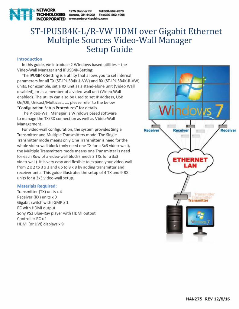
For video-wall configuration, the system provides Single Transmitter and Multiple Transmitters mode. The Single Transmitter mode means only One Transmitter is need for the whole video-wall block (only need one TX for a 3x3 video-wall), the Multiple Transmitters mode means one Transmitter is need for each Row of a video-wall block (needs 3 TXs for a 3x3 video-wall). It is very easy and flexible to expand your video-wall from 2 x 2 to 3 x 3 and up to 8 x 8 by adding transmitter and receiver units. This guide illustrates the setup of 4 TX and 9 RX units for a 3x3 video-wall setup.
Materials Required: Transmitter (TX) units x 4 Receiver (RX) units x 9 Gigabit switch with IGMP x 1 PC with HDMI output Sony PS3 Blue-Ray player with HDMI output Controller PC x 1 HDMI (or DVI) displays x 9

System Diagram

Configure ST-IPUSB4K-L/R-VW for Video-Wall Unless you specified in your Purchase Order, otherwise the Factory Default setting for the Transmitters and
Receivers are in Non-Video-Wall Mode during production. You can use the IPUSB4K-Setting utility to enable/disable
the Video-Wall setting as well as changing other parameters. The following steps show you how to use the IPUSB4K-Setting utility to verify if your TX/RX units are set in Video-Wall enabled mode. 1. Install the IPUSBRK-Setting utility (click Setup.exe). 2. Configure the controller PC’s IP address to be same as TX/RX (or 169.254.1.1 if TX/RX are in Auto IP) with Net
Mask 255.255.0.0. 3. Connect all TX and RX units with the controller PC in the same Gigabit Ethernet switch. 4. Power On all TX/RX units. 5. Run the IPUSB4K-Setting program, select the proper NIC (network interface card with 169.254.1.1). 6. The IPUSB4K-Setting will search all TX/RX units and display their current settings as below:
7. Please change the “Video Wall” setting to “Y” for all TX/RX units that are being used in video-wall as below:

8. You can also optionally set the “USB off” setting to “Y” for all TX/RX units that are being used in video-wall as below:
9. Then click “Save” button to save the settings. All TX/RX units with settings changed will be re-booted. The IPUSB4K-
Setting will show the updated settings after these units are re-booted. 10. You can also use the IPUSB4K-Setting to change the “IP Mode”, “IP Address”, “Net Mask” as well as reset the
unit to Factory Default setting by clicking the “Factory Default” and then click “Save” button.
Video-Wall Manager Setup 1 Connect 4 x HDMI sources to the Transmitter HDMI input of TX-1, TX-2, TX-3 and TX-4. 2 Set the 4-bit DIP switch of the four TX. For example, set TX-1 to “0000”, TX-2 to “0010”, TX-3 to “0011”, and
TX-4 to “0100”. 3 Set the 4-bit DIP switch of all RX to “0000”. 4 Connect all RX units to monitors by HDMI (or HDMI-to-DVI) cables. 5 Connect all TX/RX units to the Gigabit switch by CAT6 cable (CAT5e is not recommended). 6 There are 4 TXs for HDMI sources, make sure your Gigabit Ethernet switch IGMP snooping is enabled. 7 Connect the controller PC to the same Gigabit switch by CAT5e or CAT6 cable. 8 Power On all monitors, HDMI sources, Gigabit switch and all TX/RX units. 9 Install the AV-950 Video-Wall Manager (click Setup.exe). 10 Configure the controller PC’s IP address to be same as TX/RX network segment. If the TX/RX are set with the
Factory default IP setting (static IP), then set the PC IP to 10.0.1.1 with Net Mask 255.0.0.0. If you had changed the TX/RX IP to Auto IP, then you should set the PC’s IP network segment to be 169.254.1.1/255.255.0.0.
11 Run the Video-Wall Manager, and it will pop up a dialog box to lead you to select a net card that is connected to the network.

12 Then it will search all of TX/RX units then display the main window similar to the following diagram:
13 At the beginning, the status bar shows “Loading…” and a few seconds later when the search procedure is
complete, the status bar will show “Ready”. As the picture shows, the icons in white on the main blank space represent RX and those in different colors fixed on the right-hand corner represent TX. The label attached to each icon is user-defined; before it is defined by the user, it will be IP address. (For how to assign a user-defined name to a unit, refer to the later part of this guide.) Note that the program is operational only when the status bar shows “Ready”. The RX icon with a green light is an online indicator; if an RX is off the network, the program will turn the green light to gray. The TX icon, however, exhibits its existence with its color, and when a TX unit is off the network, the color will become white. There are two modes: Configuration Mode and Operation Mode. You can switch between the two by clicking the wrench icon and the wand icon on the right-hand corner. If you run the program for the first time, the program will enter the Configuration Mode when the loading is complete, and it will automatically set parameter settings of all of the units to default values, which are best for operation. Otherwise, the program will enter the Operation Mode and will not set the default settings to all of the units, even though they are new.
Create a Video-Wall
14 To create a 3x3 video-wall, select the wrench icon to enter configuration mode, then click the grid icon
on the right-hand corner to open up a window like the following “Define a Video Wall” dialogue.
Enter “3” for both Row/Column, then click OK button. A 3x3 video-wall will be created, and you can drag-and-drop the RX icon into the corresponding position like the picture below:

13 To identify the icon and the corresponding position of its monitor, you can use the RX icon’s Right-Click Context function “Show OSD (…)”, which will make the RX to display an OSD message on the monitor.
14 You can drag and drop the RX icons until they match the layout of the screens.
15 The video wall as a whole is movable; move your mouse to the border and you will see a thin surrounding border show up, as the right-hand picture shows. Look at the difference of the below two pictures; the margin on the border is where you can drag and drop the video wall.

Video-Wall Operation
16 Now you are ready to operate the video wall. Click the wand icon and you will enter the Operation mode, in which the video wall will be presented like the right-hand picture. In this example, each square represents an RX unit, and each RX is showing the complete screen of one TX source, the amber color representing that specific source.
17 Now, for example, you want to make the four RX units on the upper-left corner show a big screen, that is, each RX shows one-fourth portion of the source. The first thing to do is to multiple-select the four squares; hold <Ctrl> and click the four squares, and the video wall will be like the picture below.
Next, right-click to get a “Set Layout” pop-up window. Select the source from the drop-down items, and click on the first option “2X2 (1/4 for each tile)”, and click “OK”. Almost immediately, you will see the video wall turning into a layout like the picture below. And you can check the corresponding monitors and each should display one-fourth of the source as expected. There is, however, a short cut to achieve the same video wall layout. When you are finished selecting the tiles, just click the TX icon on the right-hand corner, and you will see the layout change to 2X2. Note that the quick operation applies only when the selected tiles are formed as a rectangle.
18 Similarly, to make each of the four RX show 1x1 of the source, just follow the same procedure, but this time,

select “1X1 for each tile” in the “Set Layout” window.
Save Video-Wall Template 19 After a video wall is done, you need to give it a name and save it,
so that you don’t have to re-create it again. As you are finished with setting the video-wall layout, please right-click on the margin and select “Save this Template” or “Save as a new Template”; these two options will give you a pop-up window like the right-hand picture. Type in the name for the template, and set a hot key, if you want.
Load Video-Wall Template 20 To load a template previously defined, please right-click
on the margin of an existing template, 3x3 for example, and select from the sub-menu items of “Load 3X3 Template”. The selections will include all pre-defined templates of the same dimension.
21 You can also load a template by right-clicking on the empty space of the main panel, but it has to be in the Operation Mode. That will give you a complete list of pre-defined templates.
22 Try hot key, if you want, and see how the template is loaded onto one of the existing templates on the main panel.
Remove or Delete a Video-Wall Template 23 “Remove” and “Delete” mean differently in this program. “Remove” means to wipe out the template from
the main panel, but it is still in the template repository. “Delete” means to delete from the repository. You can remove a template by right-click on its margin and select “Remove this Template”; when you right-click on the empty space, you will get a complete list of the templates under “Delete Template” to select from.
Scheduling a Video-Wall Template
24 On the upper-right corner, there is a button like this: . Click on the button and you will get a pop-up window to manage schedules for templates.
Scheduling enables you to add schedules for templates. As the picture above suggests, to add a schedule, just type in a name for the “Title”, select date and time you wish it to perform, and select one of the

templates from the drop-down list. When you click “Add”, there will be an entry added to the list in the upper half. To delete a schedule, just click on the entry, and click “Delete”. Note that the scheduling function works only when the program is running. If the time for one of the schedule is due, and yet the program is not running, the schedule will not be triggered.
Setting a Normal Receiver as a Controller 25 In addition to working as a part of a video wall, an RX unit can also be a controller, which allows the user to
control the connected TX through keyboard/mouse. You can change the role of an RX by right-clicking on the icon in the configuration mode, and select “Set as Controller”. In a couple of seconds, you will see the icon
turned into one like this: . To switch a controller back to a normal receiver, just follow the same steps, and select “Set as Normal Receiver”. In terms of video wall operation, a controller works just the same as a normal receiver. A controller has another advantage that a normal receiver does not have: you can switch the controller’s TX connection in Operation Mode, while for the normal receiver to connect to another TX, you have to put it in a video wall. Right-click on the controller and select from the sub-menu items of “Switch
Transmitter”. Note that there will be only one controller; if you try to set the second controller, the other controller will be set to a normal receiver automatically. And this setting is saved in the PC that runs the program; if you get another PC to run the program, you will have to set the controller again.
Set name for Input Source and Receiver 26 Input source, or TX units, and RX units can be assigned a name
for better identification. Initially they are shown with IP addresses, which are not easily identified. To name a TX unit,
select the wrench icon then move mouse to the empty floor area and then right click. The Right-Click Context menu will pop-up as the right diagram: Select the “Set Name for Input Source” then enter the name for each TX unit. Type in the name for the transmitter and press “Enter” to submit.
27 To name an RX unit, right-clicking on an RX icon, select “Set Name”, and type in a name and press “OK”.
Show OSD 28 Select/Unselect the “Show OSD” to Enable/Disable showing the OSD message of TX name (TX:xxxx) on the
screen during TX connection.
Switch Controller Automatically 29 Select/Unselect the “Switch Controller Automatically” to Enable/Disable switching the controller
automatically. In video-wall operation, sometimes you may need the stand-alone controller to connect to the same TX and to control the TX. If this option is enabled, every time you operate on a video wall of at least 2x2 dimension, the controller will automatically switch the TX connection to coincide with that of the video wall.