ssr protection it inc. meeting with ercot control remaining life ... rated-speed low-voltage short...
TRANSCRIPT

Cop
yrig
ht ©
200
1 In
stru
men
tatio
n Te
chno
logy
Inc.
-1
SSR Protection
IT Inc. Meeting with ERCOT
March 12, 2010Austin TX
Cop
yrig
ht 2
001
© In
stru
men
tatio
n Te
chno
logy
Inc.
-2

Cop
yrig
ht 2
001
© In
stru
men
tatio
n Te
chno
logy
Inc.
-3
Presentation Order
IT Inc. Resources
Application Values
The Offering
Qualification
Certification
Questions

Cop
yrig
ht 2
001
© In
stru
men
tatio
n Te
chno
logy
Inc.
-4
Instrumentation Technology Inc. Resources
Formed in 1999 SSR Protection Systems (22 turbine-generator systems) System Consulting Services - ESKOM, PG&E, XCEL, SCE, Pacificorp
Company Resources Colin Bowler IT, SSR, Power Systems Eng., Embedded Systems Design John Tarnawski Instrumentation, Embedded Systems Duncan Walker Consultant - Rotor Dynamics Dennis Ulery PE Consultant - Stress Analysis/Rotor Dynamics Mike Brown PhD U Belfast Mathematician, Controls Engineering Consulting Partner for ABB, KEMA
Technical resources Matlab / Simulink Load Flow & Stability EMTP System simulation SSR Frequency Scan & Small Signal Stability Analysis Torsional model development, Model parameter identification Torsional fatigue

Cop
yrig
ht 2
001
© In
stru
men
tatio
n Te
chno
logy
Inc.
-5
Application Values
Turbine-Generator System Interaction Concerns System faults and Transmission Operation (HSR) Controls interaction (HVDC, FACTS Transmission Devices) SSR interaction (Series capacitor compensated transmission) Steel Mill Drives and Arc furnace interactions
Application Value SSR protection
Torsional stability Shaft Fatigue
SSR Mitigation Damping Control
Remaining Life Monitoring Electromagnetic response component
Crack propagation Key-ways, Wheel disks, Blade roots
Combine torsional lateral monitoring Torsion driven crack propagation
Leading to lateral vibration Feedback on System Design
Opportunity to make changes affecting reliability
Cop
yrig
ht 2
001
© In
stru
men
tatio
n Te
chno
logy
Inc.
-6
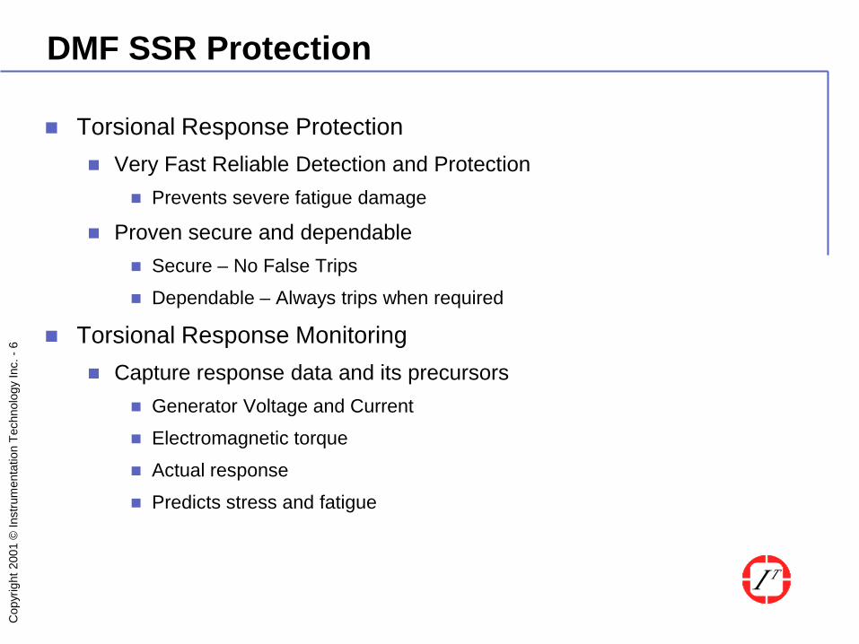
DMF SSR Protection
Torsional Response Protection Very Fast Reliable Detection and Protection
Prevents severe fatigue damage
Proven secure and dependable Secure – No False Trips
Dependable – Always trips when required
Torsional Response Monitoring Capture response data and its precursors
Generator Voltage and Current
Electromagnetic torque
Actual response
Predicts stress and fatigue

Cop
yrig
ht 2
001
© In
stru
men
tatio
n Te
chno
logy
Inc.
-7
DMF SSR Protection - Hardware
DMF module cPCI DSP system
Busmaster -Windows independent
Pentium CPU Windows 2K
GPS
Printer Keyboard mouse FT1 Simulator Signal Injection (e.g. OMICRON)
3 phase V & I Front and Rear velocity (12 sensors)
Aux relay Multi contact 1 Cycle trip
Cop
yrig
ht 2
001
© In
stru
men
tatio
n Te
chno
logy
Inc.
-8
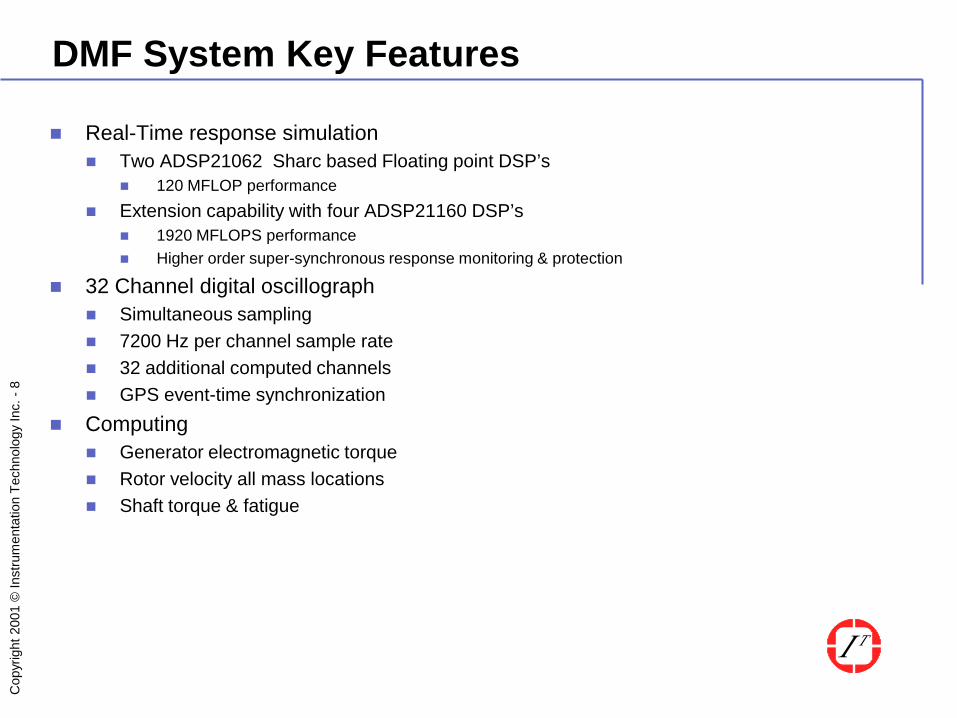
DMF System Key Features
Real-Time response simulation Two ADSP21062 Sharc based Floating point DSP’s
120 MFLOP performance Extension capability with four ADSP21160 DSP’s
1920 MFLOPS performance Higher order super-synchronous response monitoring & protection
32 Channel digital oscillograph Simultaneous sampling 7200 Hz per channel sample rate 32 additional computed channels GPS event-time synchronization
Computing Generator electromagnetic torque Rotor velocity all mass locations Shaft torque & fatigue

Cop
yrig
ht 2
001
© In
stru
men
tatio
n Te
chno
logy
Inc.
-9
DMF Module
Real Time Window Latched protection targets Shaft torque bar chart Oscillograph
Channel selection Auto & Manual trigger FFT
Hardware module Euro style cPCI CPU/Backplane Windows independent
Bus master data acquisition DSP based protection Hardware targets Trip and Alarm output
Windows dependent Data storage Data viewing Data Communication

Cop
yrig
ht 2
001
© In
stru
men
tatio
n Te
chno
logy
Inc.
-10
Oscillograph Function
Event view and selection GPS Time–stamp Event number
Channel group selection Time scale
Compression Scroll event
Channel gain control Window functions
File operations Setting operations Copy Conversion
Single event DMF format COMTRADE format EXCEL Format
Cop
yrig
ht 2
001
© In
stru
men
tatio
n Te
chno
logy
Inc.
-11
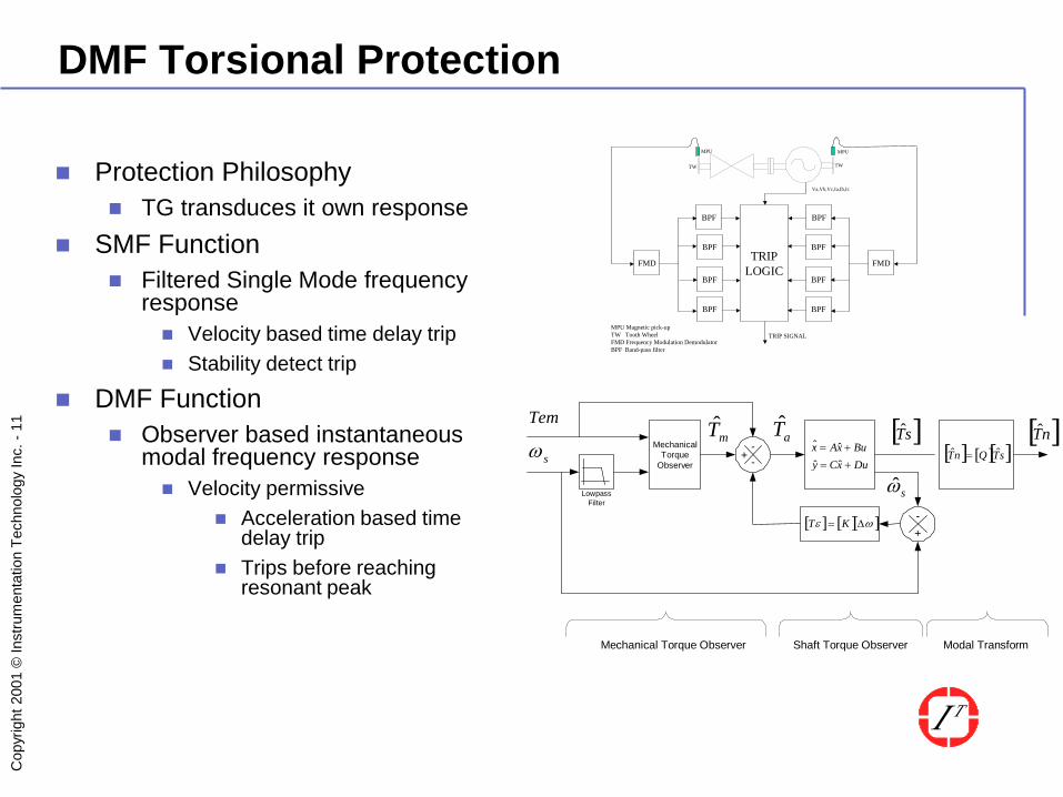
DMF Torsional Protection
Protection Philosophy TG transduces it own response
SMF Function Filtered Single Mode frequency
response Velocity based time delay trip Stability detect trip
DMF Function Observer based instantaneous
modal frequency response Velocity permissive
Acceleration based time delay trip
Trips before reaching resonant peak
Lowpass Filter
Mechanical Torque
Observer Du x C y Bu x A x
+ = + =
ˆ ˆ ˆ ˆ [ ] [ ] [ ] s T Q n T ˆ ˆ = +
- -
[ ] s T ̂ [ ] n T ̂
s ω
s ω ˆ
+ - [ ] [ ] [ ] ω ε ∆ = K T
m T ̂ a T ̂ Tem
Shaft Torque Observer Mechanical Torque Observer Modal Transform
FMD
BPF
BPF
BPF
BPF
FMD
BPF
BPF
BPF
BPF
TW TW
MPUMPU
TRIPLOGIC
Va,Vb,Vc,Ia,Ib,Ic
TRIP SIGNALMPU Magnetic pick-upTW Tooth WheelFMD Frequency Modulation DemodulatorBPF Band-pass filter

Cop
yrig
ht 2
001
© In
stru
men
tatio
n Te
chno
logy
Inc.
-12
DMF Torsional Protection
Observer based real-time process Measure applied torques & velocity Predict torsional response & shaft fatigue Acceleration feedback to converge calculated and measured instantaneous
response at key locations Current Process aimed at subsynchronous torsional protection from SSR
induced resonant response. Adaptable to any dynamic process
Especially useful where response variables are inaccessible When dynamic process is reasonably linear
Opportunity for understanding life-time issues Externalities such as system disturbances Internal stimuli such as engine-order harmonic forces Fatigue processes

Cop
yrig
ht 2
001
© In
stru
men
tatio
n Te
chno
logy
Inc.
-13
Requirements
Reasonably accurate torsional model Observer accommodates model errors
Accounts for damping variability - all sources
Appropriate response measurements Measurement locations must have observability of all modeled modes of
vibration and reject all others
Understood fatigue regime Time to crack initiation model
Crack propagation model

Cop
yrig
ht 2
001
© In
stru
men
tatio
n Te
chno
logy
Inc.
-14
Generating Accurate Models
Build physical model from geometry Account for non uniform stress distribution
Form factor variation of stiffness Elliptical & Cruciform generator rotor section
Wedge Locking Stiffening Abrupt changes in rotor diameter Shrink-fit stiffness adjustments
Calibrate physical model by test and event monitoring Model parameter identification
Applied Electromagnetic Torque, Rotor velocity, Coupling velocity
Sweep test for mode-shape and frequency Adjustments for G-field effect on blade vane stiffness
Rated-speed low-voltage short circuit test for final calibration Micro-version of actual events
Balanced and unbalanced fault

Cop
yrig
ht 2
001
© In
stru
men
tatio
n Te
chno
logy
Inc.
-15
Typical Modeling
Gas Turbine Example 140 mass reduced to 9 mass Max frequency 304 Hz TW at each end of Generator
Steam turbine example 340 mass reduced to 22 mass Max frequency 160 Hz TW at each end of TG L-0 Blade modes required

Cop
yrig
ht 2
001
© In
stru
men
tatio
n Te
chno
logy
Inc.
-16
DMF Qualification
Qualification by Real Time Event Simulation – Mohave Example
Stability Evaluation Model system for operating range
calculating torsional damping contours
Variables Units in operation Levels of line series
compensation Line outages
Establish range of conditions suitable for operation
Time response and fatigue

Cop
yrig
ht 2
001
© In
stru
men
tatio
n Te
chno
logy
Inc.
-17
DMF Qualification
Time response evaluation EMTP simulation of full range of cases
Fault type Fault timing Fault location System configuration
EMTP to COMTRADE event file generation Real-time secondary signal playback to DMF
DOBLE/OMICRON System Simulator IT tooth-wheel simulator Inject signals via FT1 switch
Compare trip actual with trip requirement from simulation
Evaluate all scenarios Evaluate security and dependability of trip DMF Scored 100%
0% False trips 100% Dependable trips
Dependable

Cop
yrig
ht 2
001
© In
stru
men
tatio
n Te
chno
logy
Inc.
-18
DMF IEC Certification

Cop
yrig
ht 2
001
© In
stru
men
tatio
n Te
chno
logy
Inc.
-19
Certification

Cop
yrig
ht 2
001
© In
stru
men
tatio
n Te
chno
logy
Inc.
-20
Certification

Cop
yrig
ht 2
001
© In
stru
men
tatio
n Te
chno
logy
Inc.
-21
Certification