s&s x-ray products catalogssxray.com/sscat.pdf · 2011-05-03 · curtain memory curtain auto...
TRANSCRIPT

S&S X-RAY PRODUCTS INC
S&S X-Ray Products Inc.1101 Linwood StreetBrooklyn NY 11208
718-649-8500800-347-XRAY
www.ssxray.com
Motorized ViewersMammography IlluminatorsX-Ray Accessories Supplies
A -1
8 0 0 /347 -XRAY
www. s s x r a y . c om
MO
TO
RIZ
ED
VIE
WE
RS
MAMMOGRAPHIC VERTICAL VIEWERMV800
Base: 2.5” CastersFinish: Attractive durable baked on polyester, in light grey with blue sides. Shelf is finished in matching blue laminate with Oak bullnose trim.Electrical: 118 volts, 60HZ AC, 1 phase, total amperage draw with all lights on and motor running-10 amps. For 220 volts, 50 HZ or other volt-ages, consult factory for details.Approx. Weight: 840 Lbs.
28.37"44.5"
30.25"
57"
71.187"
LED READOUT(FRAME NUMBER IDENTIFICATION)
AUTOMATIC SHUTOFF TIMER
POSITIONING JOY STICK
CURTAIN MEMORY CURTAIN AUTO RETRACT
SPOT LIGHT INTEN-SITY
CONTROL
PANEL SELECTORS PREVIOUS/NEXT BUTTON
LIGHT INTENSITY CONTROLCURTAIN PRESETS
CURTAIN POSITIONING
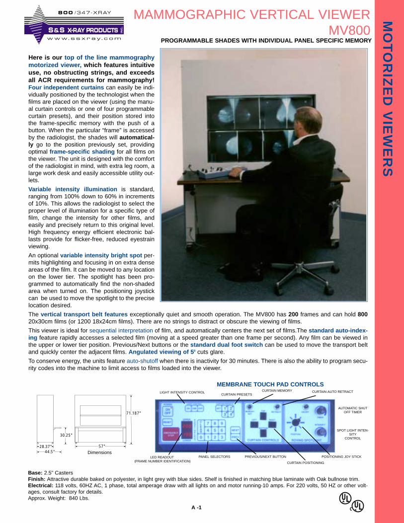
Here is our top of the line mammographymotorized viewer, which features intuitiveuse, no obstructing strings, and exceedsall ACR requirements for mammography!Four independent curtains can easily be indi-vidually positioned by the technologist when thefilms are placed on the viewer (using the manu-al curtain controls or one of four programmablecurtain presets), and their position stored intothe frame-specific memory with the push of abutton. When the particular “frame” is accessedby the radiologist, the shades will automatical-ly go to the position previously set, providingoptimal frame-specific shading for all films onthe viewer. The unit is designed with the comfortof the radiologist in mind, with extra leg room, alarge work desk and easily accessible utility out-lets.
Variable intensity illumination is standard,ranging from 100% down to 60% in incrementsof 10%. This allows the radiologist to select theproper level of illumination for a specific type offilm, change the intensity for other films, andeasily and precisely return to this original level.High frequency energy efficient electronic bal-lasts provide for flicker-free, reduced eyestrainviewing.
An optional variable intensity bright spot per-mits highlighting and focusing in on extra denseareas of the film. It can be moved to any locationon the lower tier. The spotlight has been pro-grammed to automatically find the non-shadedarea when turned on. The positioning joystickcan be used to move the spotlight to the preciselocation desired.
The vertical transport belt features exceptionally quiet and smooth operation. The MV800 has 200 frames and can hold 80020x30cm films (or 1200 18x24cm films). There are no strings to distract or obscure the viewing of films.
This viewer is ideal for sequential interpretation of film, and automatically centers the next set of films.The standard auto-index-ing feature rapidly accesses a selected film (moving at a speed greater than one frame per second). Any film can be viewed inthe upper or lower tier position. Previous/Next buttons or the standard dual foot switch can be used to move the transport beltand quickly center the adjacent films. Angulated viewing of 50 cuts glare.
To conserve energy, the units feature auto-shutoff when there is inactivity for 30 minutes. There is also the ability to program secu-rity codes into the machine to limit access to films loaded into the viewer.
MEMBRANE TOUCH PAD CONTROLS
PROGRAMMABLE SHADES WITH INDIVIDUAL PANEL SPECIFIC MEMORY
Dimensions
ULC
UL
S & S X-RAY PRODUCTS INC
.
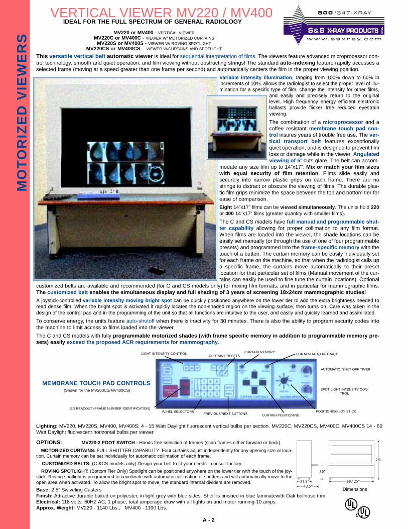
This versatile vertical belt automatic viewer is ideal for sequential interpretation of films. The viewers feature advanced microprocessor con-trol technology, smooth and quiet operation, and film viewing without obstructing strings! The standard auto-indexing feature rapidly accesses aselected frame (moving at a speed greater than one frame per second) and automatically centers the film in the proper viewing position.
Variable intensity illumination, ranging from 100% down to 60% inincrements of 10%, allows the radiologist to select the proper level of illu-mination for a specific type of film, change the intensity for other films,
and easily and precisely return to the originallevel. High frequency energy efficient electronicballasts provide flicker free reduced eyestrainviewing.
The combination of a microprocessor and acoffee resistant membrane touch pad con-trol insures years of trouble free use. The ver-tical transport belt features exceptionallyquiet operation, and is designed to prevent filmloss or damage while in the viewer. Angulatedviewing of 50 cuts glare. The belt can accom-
modate any size film up to 14”x17”. Mix or match your film sizeswith equal security of film retention. Films slide easily andsecurely into narrow plastic grips on each frame. There are nostrings to distract or obscure the viewing of films. The durable plas-tic film grips minimize the space between the top and bottom tier forease of comparison.
Eight 14”x17” films can be viewed simultaneously. The units hold 220or 400 14”x17” films (greater quantity with smaller films).
The C and CS models have full manual and programmable shut-ter capability allowing for proper collimation to any film format.When films are loaded into the viewer, the shade locations can beeasily set manually (or through the use of one of four programmablepresets) and programmed into the frame-specific memory with thetouch of a button. The curtain memory can be easily individually setfor each frame on the machine, so that when the radiologist calls upa specific frame, the curtains move automatically to their presetlocation for that particular set of films (Manual movement of the cur-tains can easily be used to fine tune the curtain locations). Optional
customized belts are available and recommended (for C and CS models only) for mixing film formats, and in particular for mammographic films.The customized belt enables the simultaneous display and full shading of 3 years of screening 18x24cm mammographic studies!
A joystick-controlled variable intensity moving bright spot can be quickly positioned anywhere on the lower tier to add the extra brightness needed toread dense film. When the bright spot is activated it rapidly locates the non-shaded region on the viewing surface, then turns on. Care was taken in thedesign of the control pad and in the programming of the unit so that all functions are intuitive to the user, and easily and quickly learned and assimilated.
To conserve energy, the units feature auto-shutoff when there is inactivity for 30 minutes. There is also the ability to program security codes intothe machine to limit access to films loaded into the viewer.
The C and CS models with fully programmable motorized shades (with frame specific memory in addition to programmable memory pre-sets) easily exceed the proposed ACR requirements for mammography.
MO
TO
RIZ
ED
VIE
WE
RS
IDEAL FOR THE FULL SPECTRUM OF GENERAL RADIOLOGY
A - 2
OPTIONS: MV220-2 FOOT SWITCH - Hands free selection of frames (scan frames either forward or back).
MOTORIZED CURTAINS: FULL SHUTTER CAPABILITY Four curtains adjust independently for any opening size or loca-tion. Curtain memory can be set individually for automatic collimation of each frame.
CUSTOMIZED BELTS: (C &CS models only) Design your belt to fit your needs - consult factory.
ROVING SPOTLIGHT: (Bottom Tier Only) Spotlight can be positioned anywhere on the lower tier with the touch of the joy-stick. Roving spotlight is programmed to coordinate with automatic collimation of shutters and will automatically move to theopen area when activated. To allow the bright spot to move, the standard internal dividers are removed.
Base: 2.5” Swiveling CastersFinish: Attractive durable baked on polyester, in light grey with blue sides. Shelf is finished in blue laminatewith Oak bullnose trim.Electrical: 118 volts, 60HZ AC, 1 phase, total amperage draw with all lights on and motor running-10 amps.Approx. Weight: MV220 - 1140 Lbs., MV400 - 1190 Lbs.
MV220 or MV400 - VERTICAL VIEWERMV220C or MV400C - VIEWER W/ MOTORIZED CURTAINS
MV220S or MV400S - VIEWER W/ ROVING SPOTLIGHTMV220CS or MV400CS - VIEWER W/CURTAINS AND SPOTLIGHT
VERTICAL VIEWER MV220 / MV400
AUTOMATIC SHUT OFF TIMER
POSITIONING JOY STICK
SPOT LIGHT INTENSITY CON-TROL
LIGHT INTENSITY CONTROL
MEMBRANE TOUCH PAD CONTROLS
PANEL SELECTORSPREVIOUS/NEXT BUTTONS
LED READOUT (FRAME NUMBER IDENTIFICATION)
27.5"43.5"
30"
69.125"
78"
Lighting: MV220, MV220S, MV400, MV400S: 4 - 15 Watt Daylight fluorescent vertical bulbs per section. MV220C, MV220CS, MV400C, MV400CS 14 - 60Watt Daylight fluorescent horizontal bulbs per viewer.
Dimensions
(Shown for the MV200CS/MV400CS)
CURTAIN POSITIONING
CURTAIN PRESETSCURTAIN MEMORY
CURTAIN AUTO RETRACT
ULC
UL
8 0 0 /347 -XRAY
www. s s x r a y . c om
S & S X-RAY PRODUCTS INC
.
A - 3
MO
TO
RIZ
ED
VIE
WE
RS
MV112A / MV112B
Base: Leveling legsFinish: Attractive durable baked on polyester, in light grey with blue sides. Shelf is finished in white laminate./ Approvals : ETLElectrical: 118 volts, 60HZ AC, 1 phase, total amperage draw with all lights on and motor running-10 amps. For 220 volts, 50 HZ or other volt-ages, consult factory for details.Approx. Weight: MV112A - 1800 lbs. MV112B - 1500 lbs.
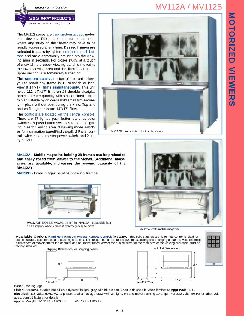
MV112A - Mobile magazine holding 28 frames can be preloadedand easily rolled from viewer to the viewer. (Additional maga-zines are available, increasing the viewing capacity of theMV112A)
MV112B - Fixed magazine of 28 viewing frames
MV112AM MOBILE MAGAZINE for the MV112A - collapsible han-dles and pivot wheels make it extremely easy to move
The MV112 series are true random access motor-ized viewers. These are ideal for departmentswhere any study on the viewer may have to berapidly accessed at any time. Desired frames areselected in pairs by lighted, numbered push but-tons and are automatically brought into the view-ing area in seconds. For closer study, at a touchof a switch, the upper viewing panel is moved tothe lower viewing area and the illumination in theupper section is automatically turned off.
The random access design of this unit allowsyou to reach any frame in 12 seconds or less.View 8 14”x17” films simultaneously. This unitholds 112 14”x17” films on 28 durable plexiglaspanels (greater quantity with smaller films). Threethin adjustable nylon cords hold small film secure-ly in place without obstructing the view. Top andbottom film grips secure 14”x17” films.
The controls are located on the central console.There are 27 lighted push button panel selectorswitches, 8 push button switches to control light-ing in each viewing area, 3 viewing mode switch-es for illumination (on/off/individual), 2 Panel con-trol switches, one master power switch, and 2 util-ity outlets.
MV112B - frames stored within the viewer
28 .75"
79"
86"
Available Option: Hand Held Random Access Remote Control: (MV112RC) This solid state electronic remote control is ideal foruse in lectures, conferences and teaching sessions. This unique hand held unit allows the selecting and changing of frames while retainingfull freedom of movement for the operator and an unobstructed view of the subject films for the members of the viewing audience. Must befactory installed.
Installed DimensionsShipping Dimensions (on shipping dollies)
28"45.625"
30"
78"
72.5"
MV112A - with mobile magazine
8 0 0 /347 -XRAY
www. s s x r a y . c om
S & S X-RAY PRODUCTS INC
.

A - 4
MO
TO
RIZ
ED
VIE
WE
RS
MV216 / MV324 / MV1436
Base: Leveling legsFinish: Attractive durable baked on polyester, in light grey with blue sides. Shelf is finished in white laminate./ Approvals : ETLElectrical: 118 volts, 60HZ AC, 1 phase, total amperage draw with all lights on and motor running- 10 amps - MV216, MV1436; 13 amps - MV324.For 220 volts, 50 HZ or other voltages, consult factory for details.Approx. Weight: MV216 - 1600 lbs MV324 - 1900 lbs. MV1436 - 1500 lbs.
28 .75"
82"
MV216 = 86"MV1436 = 86"MV324 = 114"
The MV216, MV324 and MV1436 are our larger capacitytrue random access motorized viewers.These viewersare ideal for high volume applications, where shortaccess times to any film on the motorized viewer isrequired.The random access feature minimizes the dis-ruption of clinician consultations, with rapid non-sequential retrieval of any film on the viewer, and quickreturn to the film being interpreted. Standard on theseviewers is automatic frame select (with push buttoncontrols), Individual lighting per viewing section, anddurable plexiglas panels with film grips. Each panel fea-tures adjustable thin nylon cords hold film securely inplace without obstructing vision.
Controls (MV216 - MV324): Located on the central console are thepush button panel selector buttons, individual light control buttons, mas-ter power switch, viewing mode switches and 2 utility outlets.
MV216 and MV324
Desired frames are selected by lighted, numbered pushbuttons and are automatically brought into the viewingarea in seconds. For closer study, at a touch of a switch,the upper viewing tier is moved to the lower viewing areaand the illumination in the upper section is automaticallyturned off. The MV216 holds 216 14”x17” (27 frames perunit), and displays eight 14”x17” films simultaneously.The MV324 holds 324 14”x17” (27 frames per unit), anddisplays twelve 14”x17” films simultaneously.
The MV1436 is designed specifically for the viewing of 14”x36”film. It holds 108 14”x36” (27 frames per unit) and displays four14”x36” films simultaneously. The MV1436 has four dividedviewing areas with individually controlled lighting.
Installed Dimensions
Shipping Dimensions (on shipping dollies)
28"45.625"
37"
81"
MV216 = 72.5"MV1436 = 72.5"MV324 = 100.5"
Available Option: Hand Held RandomAccess Remote Control: (MV216RC, MV324RCor MV1436RC) This solid state electronic remotecontrol is ideal for use in lectures, conferences andteaching sessions. This unique hand held unitallows the selecting and changing of frames whileretaining full freedom of movement for the operatorand an unobstructed view of the subject films for themembers of the viewing audience. Must be factoryinstalled.
Controls (MV1436): Located on the central console are27 push button panel selector buttons, 4 individual lightcontrol buttons, master power switch and 2 utility outlets.
8 0 0 /347 -XRAY
www. s s x r a y . c om
S & S X-RAY PRODUCTS INC
.
MO
TO
RIZ
ED
VIE
WE
RS
A - 5
MINI MOBILE MOTORIZED VIEWERSMV48 / MV72
Base: 4” Ball Bearing CastersFinish: Attractive durable baked on polyester, in light grey with blue sides. Shelf is finished in white laminate./ Approvals : ETLElectrical: 118 volts, 60HZ AC, 1 phase, total amperage draw with all lights on and motor running - 10 amps. For 220 volts, 50 HZ or other volt-ages, consult factory for details.Approx. Weight: MV48 - 850lbs. MV72 - 900 lbs.
70"
79"
Ship. dimension w/out shelf Ship. dimension w/out shelf
Installed dimension with optional 48AC shelf
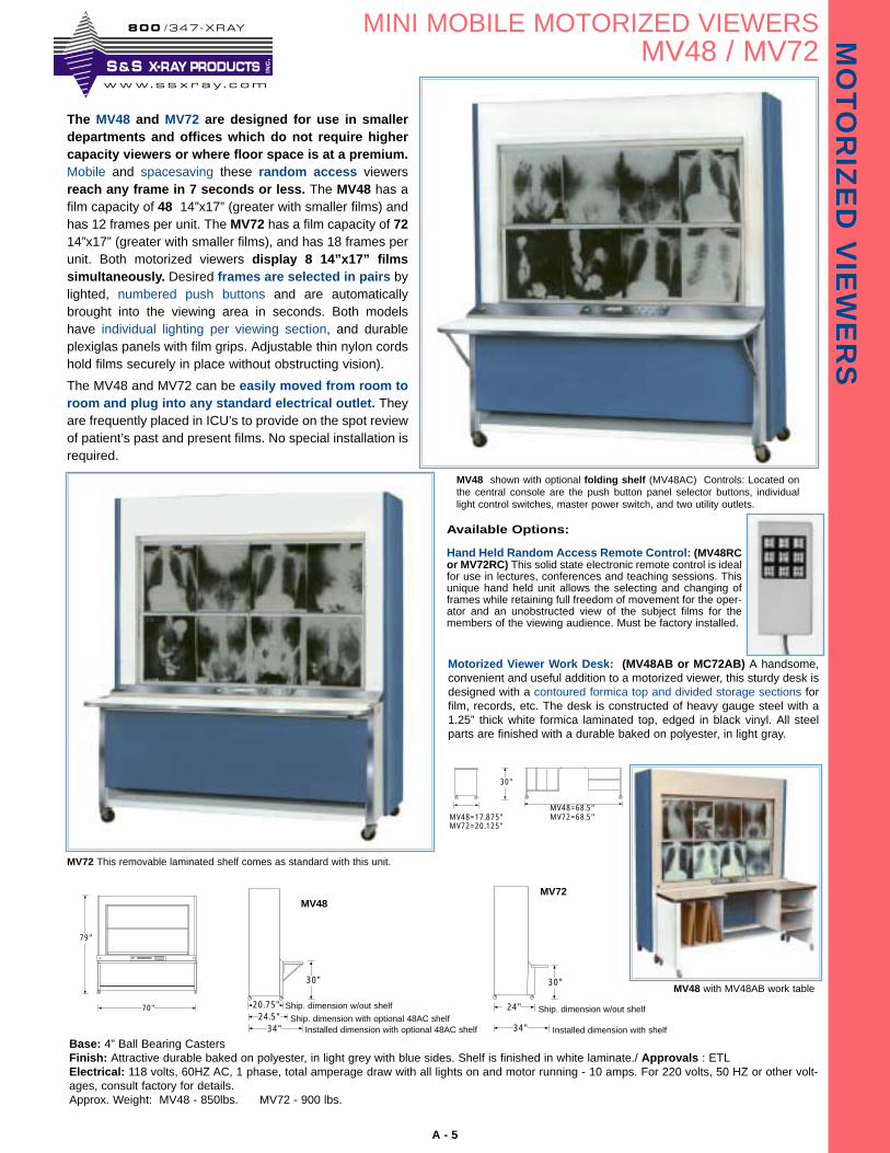
The MV48 and MV72 are designed for use in smallerdepartments and offices which do not require highercapacity viewers or where floor space is at a premium.Mobile and spacesaving these random access viewersreach any frame in 7 seconds or less. The MV48 has afilm capacity of 48 14”x17” (greater with smaller films) andhas 12 frames per unit. The MV72 has a film capacity of 7214”x17” (greater with smaller films), and has 18 frames perunit. Both motorized viewers display 8 14”x17” filmssimultaneously. Desired frames are selected in pairs bylighted, numbered push buttons and are automaticallybrought into the viewing area in seconds. Both modelshave individual lighting per viewing section, and durableplexiglas panels with film grips. Adjustable thin nylon cordshold films securely in place without obstructing vision).
The MV48 and MV72 can be easily moved from room toroom and plug into any standard electrical outlet. Theyare frequently placed in ICU’s to provide on the spot reviewof patient’s past and present films. No special installation isrequired.
MV72 This removable laminated shelf comes as standard with this unit.
20.75"24.5"
30"
34"
24"
34"
30"
Ship. dimension with optional 48AC shelfInstalled dimension with shelf
MV48MV72
Motorized Viewer Work Desk: (MV48AB or MC72AB) A handsome,convenient and useful addition to a motorized viewer, this sturdy desk isdesigned with a contoured formica top and divided storage sections forfilm, records, etc. The desk is constructed of heavy gauge steel with a1.25” thick white formica laminated top, edged in black vinyl. All steelparts are finished with a durable baked on polyester, in light gray.
MV48=17.875"MV72=20.125"
MV48=68.5"MV72=68.5"MV810-170=63"
30"
Available Options:
Hand Held Random Access Remote Control: (MV48RCor MV72RC) This solid state electronic remote control is idealfor use in lectures, conferences and teaching sessions. Thisunique hand held unit allows the selecting and changing offrames while retaining full freedom of movement for the oper-ator and an unobstructed view of the subject films for themembers of the viewing audience. Must be factory installed.
MV48 with MV48AB work table
MV48 shown with optional folding shelf (MV48AC) Controls: Located onthe central console are the push button panel selector buttons, individuallight control switches, master power switch, and two utility outlets.
8 0 0 /347 -XRAY
www. s s x r a y . c om
S & S X-RAY PRODUCTS INC
.
A - 6
MO
TO
RIZ
ED
VIE
WE
RS
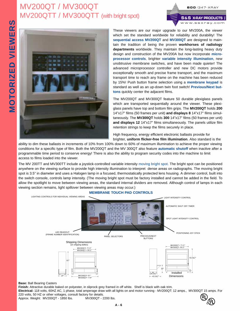
MV200QT / MV300QTMV200QTT / MV300QTT (with bright spot)
These viewers are our major upgrade to our MV200A, the viewerwhich set the standard worldwide for reliability and durability! Thesequential access MV200QT and MV300QT are designed to main-tain the tradition of being the proven workhorses of radiologydepartments worldwide. They maintain the long-lasting heavy dutydesign and construction of the MV200A but now incorporate micro-processor controls, brighter variable intensity illumination, newunobtrusive membrane switches, and have been made quieter! Theadvanced microprocessor controller and new DC motors provideexceptionally smooth and precise frame transport, and the maximumtransport time to reach any frame on the machine has been reducedby 15%! Push button frame selection using a membrane keypad isstandard as well as an up-down twin foot switch! Previous/Next but-tons quickly center the adjacent films.
The MV200QT and MV300QT feature 50 durable plexiglass panelswhich are transported sequentially around the viewer. These plexi-glass panels have top and bottom film grips. The MV200QT holds 20014”x17” films (50 frames per unit) and displays 8 14”x17” films simul-taneously. The MV300QT holds 300 14”x17” films (50 frames per unit)and displays 12 14”x17” films simultaneously. The panels utilize filmretention strings to keep the films securely in place.
High frequency, energy efficient electronic ballasts provide forbrighter, uniform flicker-free film illumination. Also standard is the
ability to dim these ballasts in increments of 10% from 100% down to 60% of maximum illumination to achieve the proper viewingconditions for a specific type of film. Both the MV200QT and the MV 300QT also feature automatic shutoff when inactive after aprogrammable time period to conserve energy! There is also the ability to program security codes into the machine to limitaccess to films loaded into the viewer.
The MV 200TT and MV300TT include a joystick-controlled variable intensity moving bright spot. The bright spot can be positionedanywhere on the viewing surface to provide high intensity illumination to interpret dense areas on radiographs. The moving brightspot is 3.5” in diameter and uses a Halogen lamp in a focused, thermostatically protected lens housing. A dimmer control, built intothe switch console, controls lamp intensity. (The moving bright spot must be factory installed and cannot be added in the field. Toallow the spotlight to move between viewing areas, the standard internal dividers are removed. Although control of lamps in eachviewing section remains, light spillover between viewing areas may occur.)
Base: Ball Bearing CastersFinish: Attractive durable baked on polyester, in sliprock grey framed in off white. Shelf is black with oak trim.Electrical: 118 volts, 60HZ AC, 1 phase, total amperage draw with all lights on and motor running - MV200QT: 12 amps., MV300QT 15 amps. For220 volts, 50 HZ or other voltages, consult factory for details.Approx. Weight: MV200QT - 1850 lbs. MV300QT - 2200 lbs.
LIGHTING CONTROLS FOR INDIVIDUAL VIEWING AREAS
AUTOMATIC SHUT OFF TIMER
POSITIONING JOY STICK
SPOT LIGHT INTENSITY CONTROL
LIGHT INTENSITY CONTROL
MEMBRANE TOUCH PAD CONTROLS
MV200QT= 71.5"MV300QT = 99.5"
29"
82"
MV200QT= 91"MV300QT= 119"
Shipping Dimensions(on shipping dollies)
PANEL SELECTORS PREVIOUS/NEXTBUTTONS
LED READOUT(FRAME NUMBER IDENTIFICATION)
28.562"
43.562"
93.562"
MV200QT = 71.5"MV300QT= 99.5"
14"30"
InstalledDimensions
ULC
UL
8 0 0 /347 -XRAY
www. s s x r a y . c om
S & S X-RAY PRODUCTS INC
.
A - 7
MO
TO
RIZ
ED
VIE
WE
RS
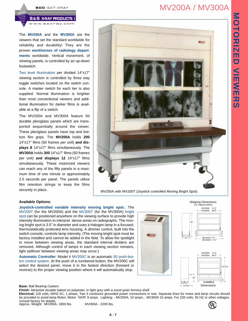
MV200A / MV300A
The MV200A and the MV300A are theviewers that set the standard worldwide forreliability and durability! They are theproven workhorses of radiology depart-ments worldwide. Vertical movement, ofviewing panels, is controlled by an up-downfootswitch.
Two level illumination per divided 14”x17”viewing section is controlled by three waytoggle switches located on the switch con-sole. A master switch for each tier is alsosupplied. Normal illumination is brighterthan most conventional viewers and addi-tional illumination for darker films is avail-able at a flip of a switch.
The MV200A and MV300A feature 50durable plexiglass panels which are trans-ported sequentially around the viewer.These plexiglass panels have top and bot-tom film grips. The MV200A holds 20014”x17” films (50 frames per unit) and dis-plays 8 14”x17” films simultaneously. TheMV300A holds 300 14”x17” films (50 framesper unit) and displays 12 14”x17” filmssimultaneously. These motorized viewerscan reach any of the fifty panels in a maxi-mum time of one minute or approximately2.5 seconds per panel. The panels utilizefilm retention strings to keep the filmssecurely in place.
Base: Ball Bearing CastersFinish: Attractive durable baked on polyester, in light grey with a wood grain formica shelf.Electrical: 118 volts, 60HZ AC, 1 phase. Two 3 conductor grounded power connections in rear. Separate lines for motor and lamp circuits shouldbe provided to avoid lamp flicker. Motor: 1/2HP, 9 amps. Lighting: - MV200A: 10 amps., MV300A 15 amps. For 220 volts, 50 HZ or other voltages,consult factory for details.Approx. Weight: MV200A- 1850 lbs. MV300A - 2200 lbs.
MV200QT= 71.5"MV300QT = 99.5"
29"
82"
MV200QT= 91"MV300QT= 119"
Shipping Dimensions(on shipping dollies)
28.562"
43.562"
93.562"
MV200QT = 71.5"MV300QT= 99.5"
14"30"
InstalledDimensions
Available Options:
Joystick-controlled variable intensity moving bright spot.: TheMV200T (for the MV200A) and the MV300T (for the MV300A) brightspot can be positioned anywhere on the viewing surface to provide highintensity illumination to interpret dense areas on radiographs. The mov-ing bright spot is 3.5” in diameter and uses a Halogen lamp in a focused,thermostatically protected lens housing. A dimmer control, built into theswitch console, controls lamp intensity. (The moving bright spot must befactory installed and cannot be added in the field. To allow the spotlightto move between viewing areas, the standard internal dividers areremoved. Although control of lamps in each viewing section remains,light spillover between viewing areas may occur.)
Automatic Controller: Model # MV200C is an automatic 50 push-but-ton control system. At the push of a numbered button, the MV200C willselect the desired panel, move it in the fastest direction (forward orreverse) to the proper viewing position where it will automatically stop.
MV200A 71.5”MV300A 99.5”
MV200A 71.5”MV300A 99.5”
MV200A with MV200T (Joystick controlled Moving Bright Spot)
ULC
8 0 0 /347 -XRAY
www. s s x r a y . c om
S & S X-RAY PRODUCTS INC
.
B - 1
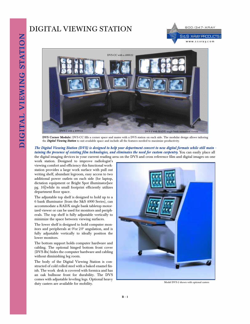
DIGITAL VIEWING STATION
The Digital Viewing Station (DVS) is designed to help your department convert to new digital formats while still main -taining the presence of existing film technologies, and eliminates the need for custom carpentry. You can easily place allthe digital imaging devices in your current reading area on the DVS and cross reference film and digital images on onework station. Designed to improve radiologist’sviewing comfort and efficiency this functional work-station provides a large work surface with pull outwriting shelf, abundant legroom, easy access to twoadditional power outlets on each side (for laptop,dictation equipment or Bright Spot illuminator[seepg. 16])while its small footprint efficiently utilizesdepartment floor space.
The adjustable top shelf is designed to hold up to a6 bank illuminator (from the S&S 4000 Series), canaccommodate a RADX single bank tabletop motor-ized viewer or can be used for monitors and periph-erals. The top shelf is fully adjustable vertically tominimize the space between viewing surfaces.
The lower shelf is designed to hold computer mon-itors and peripherals at 00or 200 angulation, and isfully adjustable vertically to ideally position thelower monitors.
The bottom support holds computer hardware andcabling. The optional hinged bottom front cover(DVS-Bx) hides the computer hardware and cablingwithout diminishing leg room.
The body of the Digital Viewing Station is con-structed of cold rolled steel with a baked enamel fin-ish. The work desk is covered with formica and hasan oak bullnose front for durability. The DVScomes with adjustable leveling legs. Optional heavyduty casters are available for mobility.
DVS Corner Module: DVS-CC fills a corner space and mates with a DVS station on each side. The modular design allows tailoringthe Digital Viewing Station to suit available space and include all the features needed to maximize productivity.
Model DVS-2 shown with optional casters
DVS-4 with RADX single bank motorized viewer
DVS-CC with a 400022
DVS-2 with a 400024
8 0 0 / 3 4 7 - X R AY
S & S X- R AY PR O D UCTSw w w. s s x ra y. c o m
B - 2
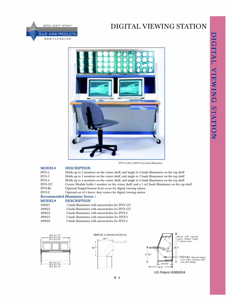
DIGITAL VIEWING STATION
DV S-2 57”DV S -3 69”D V S-4 93”
D V S-2 61”D V S-3 73”D V S-4 97”
31.28”
46.4”
29.656”
58.5”48.7”
48.7”
DVS-CC CORNER MODULE
MODEL# DESCRIPTIONDVS-2 Holds up to 2 monitors on the center shelf, and single to 4 bank illuminator on the top shelfDVS-3 Holds up to 3 monitors on the center shelf, and single to 5 bank illuminator on the top shelfDVS-4 Holds up to 4 monitors on the center shelf, and single to 6 bank illuminator on the top shelfDVS-CC Corner Module holds 1 monitor on the center shelf, and a 1 or2 bank illuminator on the top shelfDVS-Bx Optional hinged bottom front cover for digital viewing station DVS-C Optional set of 4 heavy duty casters for digital viewing stationRecommended Illuminator Series :MODEL# DESCRIPTION400021 1 bank illuminator with autoswitches for DVS- CC400022 2 bank illuminator with autoswitches for DVS- CC400024 4 bank illuminator with autoswitches for DVS-2400025 5 bank illuminator with autoswitches for DVS-3400026 6 bank illuminator with autoswitches for DVS-4
DVS-Bx Optional hingedcover (hides computer hard-ware and cabling)
Shown with optionalcasters. Reduce height3” without casters
DVS-2 with a 400024 four bank illuminator
8 0 0 / 3 4 7 - X R AY
S &S X- R AY PR O D UCTSw w w . s s x ra y. c o m
US Patent #5980004
B - 3
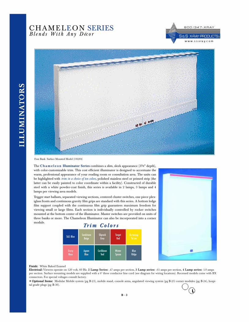
The Ch a m e l e o n Illuminator Series combines a slim, sleek appearance (33/8” depth),with color-customizable trim. This cost efficient illuminator is designed to accentuate thewarm, professional appearance of your reading room or consultation area. The units canbe highlighted with trim in a choice of ten colors, polished stainless steel or primed strip (thelatter can be easily painted to color coordinate within a facility). Constructed of durablesteel with a white powder-coat finish, this series is available in 2 lamps, 3 lamps and 4lamps per viewing area models.
Trigger start ballasts, separated viewing sections, centered cluster switches, one piece plex-iglass fronts and continuous gravity film grips are standard with this series. A bottom ledgefilm support coupled with the continuous film grip guarantees maximum freedom forviewing small or large films. Each section is individually controlled by rocker switchesmounted at the bottom center of the illuminator. Master switches are provided on units ofthree banks or more. The Chameleon Illuminator can also be incorporated into a cornermodule.
Finish: White Baked Enamel Electrical: Viewers operate on 120 volt, 60 Hz. 2 Lamp Series: .47 amps per section, 3 Lamp series: .61 amps per section, 4 Lamp series: 1.0 ampsper section. Surface mounting models are supplied with a 6’ three conductor line cord (see diagram for wiring locations). Recessed models come with BXconnectors. For special voltages consult factory.✶ Optional Items: Modular Mobile system (pg B-23), mobile stand, console arms, angulated viewing system (pg B-25) corner modules (pg B-24), hospi-tal grade plugs (pg B-30).
CHAM E LEON SERIESB l e n d s Wi t h An y D éc o r
Four Bank Surface Mounted Model (101204)
Tr i m C o l o r s
8 0 0 / 3 4 7 - X R AY
S & S X- R AY PR O D UCTSw w w. s s x ra y. c o m
S&S BlueSandstone
BeigeSliprockGrey
TargetRed
DustyRose
AgeanBlue
CaribbeanTeal
WinterSpruce
BlueRidge
ButtercupYellow
B - 4
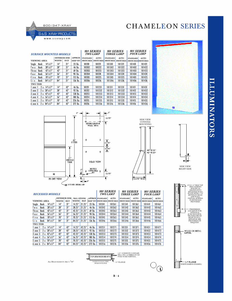
CHAM E LEON SERIES
101 SERIESTWO LAMP
101 SERIESFOUR LAMP
Single Bank 14”x17” 14” 21” 14 . 2 5” 21 . 2 5 ” 23 lbsT w o Bank 28”x17” 28” 21” 28.2 5” 21 . 2 5 ” 46 lbsTh r e e Bank 42”x17” 42” 21” 42. 2 5 ” 21 . 2 5 ” 69 lbsF o u r Bank 56”x17” 56” 21” 56. 2 5 ” 21 . 2 5 ” 90 lbsF i v e Bank 70”x17” 70” 21” 70. 2 5 ” 21 . 2 5 ” 113 lbsS i x Bank 84”x17” 84” 21” 84. 2 5 ” 21 . 2 5 ” 136 lbs
1 over 1 2 x 14”x17” 14” 42” 14. 2 5 ” 42 . 2 5” 46 lbs2 over 2 2 x 28”x17” 28” 42” 28. 2 5 ” 42 . 2 5” 92 lbs3 over 3 2 x 42”x17” 42” 42” 42. 2 5 ” 42 . 2 5” 138 lbs4 over 4 2 x 56”x17” 56” 42” 56. 2 5 ” 42 . 2 5” 180 lbs5 over 5 2 x 70”x17” 70” 42” 70. 2 5 ” 42 . 2 5” 226 lbs6 over 6 2 x 84”x17” 84” 42” 84. 2 5 ” 42 . 2 5” 272 lbs
VIEWING AREA
TWO TIER
RECESSED MODELS
WIDTH HGT SHIP WT
EXTERIOR DIM APPROX STANDARD
SWITCHESSTANDARD
SWITCHESAUTO
SWITCHESAUTO
SWITCHES
101 SERIESTHREE LAMP
WALL OPENING STANDARD
SWITCHESAUTO
SWITCHES
101241 101261 1013 41 101361 101441 1014 61101242 101262 1013 42 101362 101442 1014 62101243 10126 3 1013 43 10136 3 101443 1014 6 3101244 10126 4 1013 44 10136 4 101444 1014 6 4101245 101265 1013 45 101365 101445 1014 6510124 6 101266 1013 4 6 101366 10144 6 1014 66
1012 51 101271 101351 101371 101451 1014 711012 52 101272 101352 101372 101452 1014 721012 53 101273 101353 101373 101453 1014 731012 54 101274 101354 101374 101454 1014 741012 55 101275 101355 101375 101455 1014 751012 56 101276 101356 101376 101456 1014 76
Single Bank 14”x17” 14” 21” 23 lbs 101201 101221 101301 101321 101401 101421T w o Bank 28”x17” 28” 21” 46 lbs 101202 101222 1013 0 2 10132 2 10140 2 10142 2T h r e e Bank 42”x17” 42” 21” 69 lbs 101203 101223 1013 0 3 10132 3 10140 3 10142 3F o u r Bank 56”x17” 56” 21” 90 lbs 101204 101224 1013 0 4 101324 10140 4 101424F i v e Bank 70”x17” 70” 21” 113 lbs 101205 101225 1013 05 10132 5 101405 10142 5S i x Bank 84”x17” 84” 21” 136 lbs 101206 101226 1013 0 6 101326 10140 6 101426
1 over 1 2 x 14”x17” 14” 42” 46 lbs 101211 1012 31 101311 101331 101411 1014312 over 2 2 x 28”x17” 28” 42” 92 lbs 101212 1012 32 101312 101332 101412 1014323 over 3 2 x 42”x17” 42” 42” 138 lbs 101213 1012 3 3 101313 10133 3 101413 10143 34 over 4 2 x 56”x17” 56” 42” 180 lbs 101214 1012 3 4 101314 10133 4 101414 10143 45 over 5 2 x 70”x17” 70” 42” 226 lbs 101215 1012 35 101315 101335 101415 1014356 over 6 2 x 84”x17” 84” 42” 272 lbs 101216 1012 36 101316 101336 101416 101436
101 SERIESTHREE LAMP
VIEWING AREASTANDARD
SWITCHESSTANDARD
SWITCHESAUTO
SWITCHESAUTO
SWITCHES
TWO TIER
SURFACE MOUNTED MODELS101 SERIESTWO LAMP
WIDTH HGT SHIP WT
EXTERIOR DIM APPROX
101 SERIESFOUR LAMP
STANDARD
SWITCHESAUTO
SWITCHES
WIDTH HGT
ALL MEASUREMENTS ARE ± 1/16”
1/2” CONDUIT C ONTAIN-ING 3 NO. 14 WIRES TO 120VOLT 60 HZ S ERVICE. .
1.5” FLANGEFASTEN TO WALL THRUHOLES IN FLANGE
(WHITE BAKED ENAMEL)
SIDE VIEWRIGHT SIDE
SIDE VIEWCONSOLE
MOUNTING
#10 X 1.5” SELF TAP-PING SCREWS
SPACED ASSHOWN INTO
RECESSED WALLPLATE WITH 1/16”BETWEEN HEAD
AND WALL.INSTALL SCREWS
IN KEYHOLESPROVIDED.
PREFERREDLOCATION FOR
OPTIONALJUNCTION BOX.PIGTAILS FROMREAR OF ILLU-MINATOR AREPROVIDED ON
REQUEST.
8 0 0 / 3 4 7 - X R AY
S &S X- R AY PR O D UCTSw w w . s s x ra y. c o m
B - 5
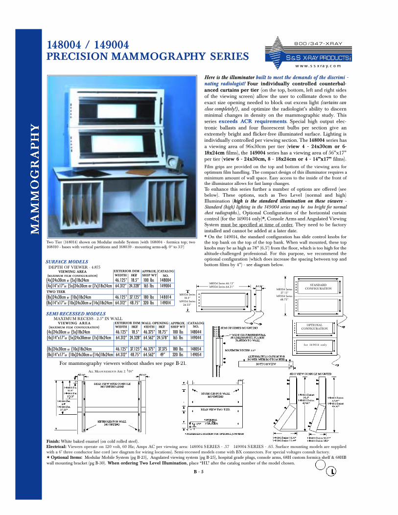
148004 / 149004 PRECISION MAMMOGRAPHY SERIES
Here is the illuminator built to meet the demands of the discrimi -nating radiologist! Four individually controlled counterbal-anced curtains per tier (on the top, bottom, left and right sidesof the viewing screen) allow the user to collimate down to theexact size opening needed to block out excess light (curtains canclose completely!) , and optimize the radiologist’s ability to discernminimal changes in density on the mammographic study. Thisseries exceeds ACR requirements. Special high output elec-tronic ballasts and four fluorescent bulbs per section give anextremely bright and flicker-free illuminated surface. Lighting isindividually controlled per viewing section. The 148004 series hasa viewing area of 96x30cm per tier (view 4 - 24x30cm or 6-18x24cm films), the 149004 series has a viewing area of 56”x17”per tier (view 6 - 24x30cm, 8 - 18x24cm or 4 - 14”x17” films).Film grips are provided on the top and bottom of the viewing area foroptimum film handling. The compact design of this illuminator requires aminimum amount of wall space. Easy access to the inside of the front ofthe illuminator allows for fast lamp changes.To enhance this series further a number of options are offered (seebelow). These options, such as Two Level (normal and high)Illumination (high is the standard illumination on these viewers -Standard (high) lighting in the 149004 series may be too bright for normalchest radiographs.), Optional Configuration of the horizontal curtaincontrol (for the 149014 only)*, Console Arms and Angulated ViewingSystem must be specified at time of order. They need to be factoryinstalled and cannot be added at a later date. * On the 149014, the standard configuration has slide control knobs forthe top bank on the top of the top bank. When wall mounted, these topknobs may be as high as 78” (6.5’) from the floor, which is too high for thealtitude-challenged professional. For this purpose, we recommend theoptional configuration (which does increase the spacing between top andbottom films by 4”) - see diagram below.
Finish: White baked enamel (on cold rolled steel). Electrical: Viewers operate on 120 volt, 60 Hz; Amps AC per viewing area: 148004 SERIES - .57 149004 SERIES - .65. Surface mounting models are suppliedwith a 6’ three conductor line cord (see diagram for wiring locations). Semi-recessed models come with BX connectors. For special voltages consult factory.✶ Optional Items: Modular Mobile System (pg B-23), Angulated viewing system (pg B-25), hospital grade plugs, console arms, 68H custom formica shelf & 68HBwall mounting bracket (pg B-30). When ordering Two Level Illumination, place “HL” after the catalog number of the model chosen.
TWO TIER
SEMI-RECESSED MODELS
APPROX. CATALOGNO.
WALL OPENINGWIDTH HGT
DEPTH OF VIEWER - 4.875
(4x)24x30cm or (5x)18x24cm 46.125” 18.5” 100 lbs 148004(4x)14”x17”or (5x)24x30cm or (7x)18x24cm 64.312” 24.328” 165 lbs 149004
(8x)24x30cm or (10x)18x24cm 46.125” 37.125” 180 lbs 14 8 014(8x)14”x17”or (10x)24x30cm or (14x)18x24cm 64.312” 48.75” 320 lbs 149014
VIEWING AREA(MAXIMUM FILM CONFIGURATION)
TWO TIER
SURFACE MODELS
WIDTH HGT SHIP WTEXTERIOR DIM APPROX. CATALOG
NO.
Two Tier (148014) shown on Modular mobile System (with 168004 - formica top; two168010 - bases with vertical partitions and 168039 - mounting arms-adj. 0 0 to 350)
STANDARDCONFIGURATION
OPTIONAL CONFIGURATION
for 14 9014 onl y
148004 Series37.13”
149004 Series48.75”
148004 Series18.5”
149004 Series24.33”
148004 Series 46.13”149004 Series 64.31”
MAXIMUM RECESS - 2.5” IN WALLV I EW I NG AR E A
(MAXIMUM FILM CONFIGURATION)EXTERIOR DIMWIDTH HGT SHIP WT
(4x)24x30cm or (5x)18x24cm 46.125” 18.5” 46.375” 18.75” 100 lbs 148044(4x)14”x17”or (5x)24x30cmor (7x)18x24cm 64.312” 24.328” 64.562” 24.578” 165 lbs 149044
(8x)24x30cm or (10x)18x24cm 46.125” 37.125” 46.375” 37.375 180 lbs 148054(8x)14”x17”or (10x)24x30cm or (14x)18x24cm 64.312” 48.75” 64.562” 49” 320 lbs 149054
ALL MEASUREMENTS ARE ± 1/16”
For mammography viewers without shades see page B-21.
8 0 0 / 3 4 7 - X R AY
S & S X- R AY PR O D UCTSw w w. s s x ra y. c o m

B - 6
149005/149055PRECISION MAMMOGRAPHY
This quality illuminator is designed for the ease of comparison ofsequential mammographic studies. Extraneous light is quicklyand accurately collimated out using our unique, counterbalancedmanual shades (which can close completely). High output, energyefficient, electronic ballasts minimize noise and eliminate theneed for annoying fans. Nine F40/D865 daylight fluorescentbulbs and variable intensity lighting, ranging from 100% down to60% in increments of 10%, allow the radiologist to select an optimallevel of illumination for a specific type of film, change the inten-sity for other films, and easily and precisely return to this origi-nal level. The combination of four independently operatedshades for precise collimation with minimal penumbra, andextremely bright and uniform variable intensity illumination,maximize the radiologists ability to uncover important subtlechanges on mammograms. This illuminator exceeds ACRrequirements.
The unique design of this illuminator also allows its customiza-tion for different format films. Four film grips, with anadjustable center film grip, permit customized film placement onthe uniformly illuminated surface. Adjustment of this centerfilm grip allows the viewing of up to eight 24x30cm or twelve18x24cm films with no extraneous light to hinder reading. Byrepositioning the center film grip three 14”x17” films can be read.
For mammography viewers without shades see page B-21.
Consult factory for other configurations.
Finish: White baked enamel (on cold rolled steel). / Electrical: Viewers operate on 120 volt, 60 Hz; 2.7 Amps AC. Surface mount models are supplied with a 6’ three conductor line cord (see diagram forwiring locations). Recessed models come with BX connectors. For special voltages consult factory.✶ Optional Items: Modular Mobile System (pg B-23), hospital grade plugs, 68H custom formica shelf & 68HB wall mounting bracket (pg B-30).
MAXIMUM RECESS - 2.5” IN WALL
(3x)14”x17”or (8x)24x30cm or (12x)18x24cm 53.843” 31.812” 54.093” 32.062” 182 lbs 149055
VIEWING AREA(MAXIMUM FILM CONFIGURATION)
SEMI-RECESSED MODELS
WIDTH HGT SHIP WTEXTERIOR DIM APPROX. CATALOG
NO.WALL OPENINGWIDTH HGT
DEPTH OF VIEWER - 4.875
(3x)14”x17”or (8x)24x30cm or (12x)18x24cm 53.843” 31.812” 180 lbs 149005
VIEWING AREA(MAXIMUM FILM CONFIGURATION)
SURFACE MODEL
WIDTH HGT SHIP WTEXTERIOR DIM APPROX. CATALOG
NO.
Configured for viewing 24x30cm film. Shown on Modular mobile System (with 168004- formica top; 168011- base with pull out shelf; 168010 - base with vertical partitionsand 168040 - mounting arms)
Configured for viewing 14”x17” film
ALL MEASUREMENTS ARE ± 1/16”
8 0 0 / 3 4 7 - X R AY
S &S X- R AY PR O D UCTSw w w . s s x ra y. c o m
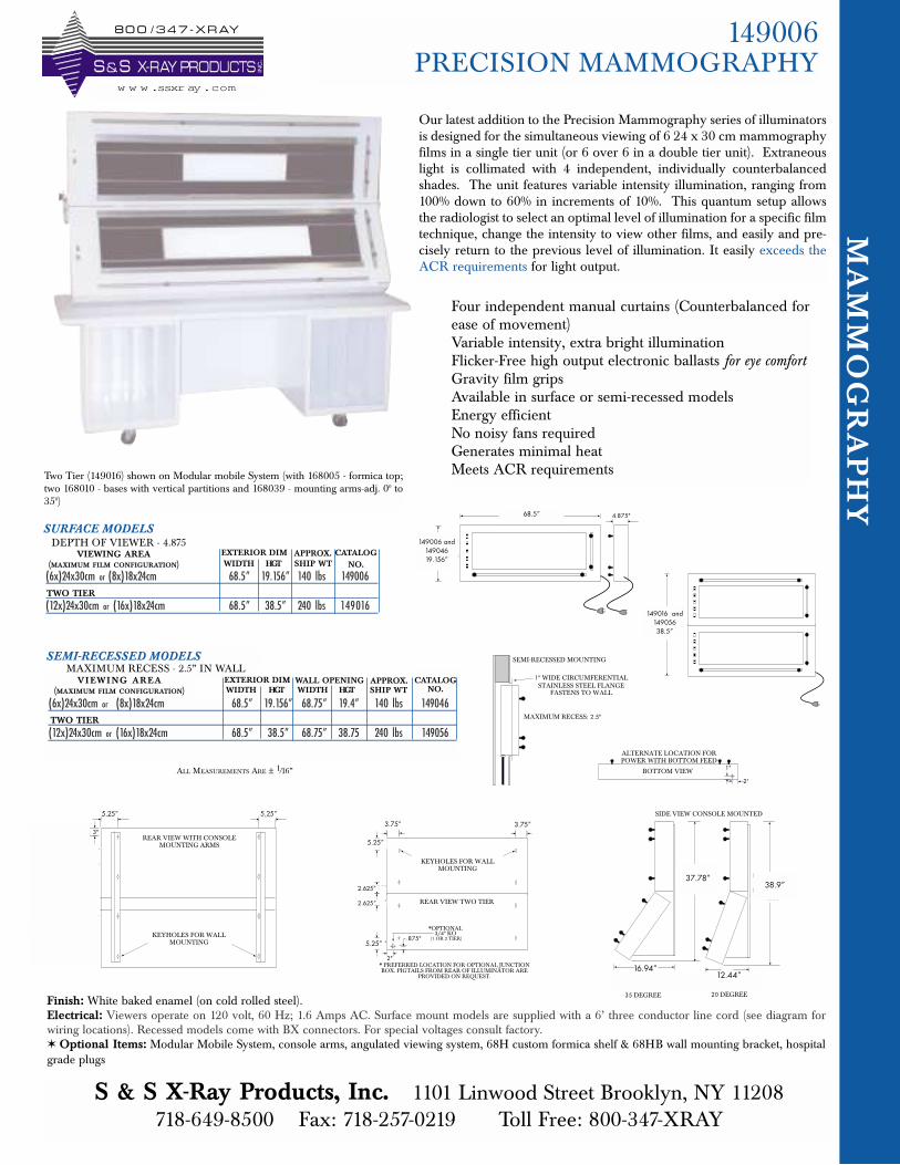
149006 PRECISION MAMMOGRAPHY
MA
MM
OG
RA
PH
Y8 0 0 / 3 4 7 - X R AY
INC
.
S & S X-RAY PRODUCTSw w w .ssxray.com
148000 Series:46.13"149000 Series:64.31"
4.875"
148000 Series:18.5"
149000 Series:24.33"
REAR VIEW TWO TIER
KEYHOLES FOR WALLMOUNTING
*OPTIONAL3/4" KO
* PREFERRED LOCATION FOR OPTIONAL JUNCTIONBOX. PIGTAILS FROM REAR OF ILLUMINATOR ARE
PROVIDED ON REQUEST.
(1 OR 2 TIER)
3.25" 3.25"
3.25"
3.25"
3.25"
3.25"
2"
.875"
SIDE VIEW CONSOLE MOUNTED
148000 Series:12.21"149000 Series:14.2"
35 DEGREE 20 DEGREE
148000 Series:37.59"
149000 Series:48.88"
148000 Series:36.5"
149000 Series:47.06"
148000 Series:16.38"149000 Series:19.84"
BOTTOM VIEW
ALTERNATE LOCATION FORPOWER WITH BOTTOM FEED
1"
2"
TWO TIER
SEMI-RECESSED MODELS
APPROX. CATALOGNO.
WALL OPENINGWIDTH HGT
DEPTH OF VIEWER - 4.875
(6x)24x30cm or (8x)18x24cm 68.5” 19.156” 140 lbs 149006
(12x)24x30cm or (16x)18x24cm 68.5” 38.5” 240 lbs 149016
VIEWING AREA(MAXIMUM FILM CONFIGURATION)
TWO TIER
SURFACE MODELS
WIDTH HGT SHIP WTEXTERIOR DIM APPROX. CATALOG
NO.
148000 Series:37.13"
149000 Series:48.75"
SEMI-RECESSED MOUNTING
MAXIMUM RECESS: 2.5"
1" WIDE CIRCUMFERENTIALSTAINLESS STEEL FLANGE
FASTENS TO WALL
149016 and14905638.5”
149006 and14904619.156”
68.5”
MAXIMUM RECESS - 2.5” IN WALLVI EWI NG AREA
(MAXIMUM FILM CONFIGURATION)EXTERIOR DIMWIDTH HGT SHIP WT
(6x)24x30cm or (8x)18x24cm 68.5” 19.156” 68.75” 19.4” 140 lbs 149046
(12x)24x30cm or (16x)18x24cm 68.5” 38.5” 68.75” 38.75 240 lbs 149056
REAR VIEW WITH CONSOLEMOUNTING ARMS
KEYHOLES FOR WALLMOUNTING
4.687" 4.687"
3"
148000 Ser.34.5"
149000 Ser.45.36"
148000 Ser.24"
149000 Ser.31.25"
148000 Ser.13.5"
149000 Ser.17.13"
ALL MEASUREMENTS ARE ± 1/16”
TWO TIER
Our latest addition to the Precision Mammography series of illuminatorsis designed for the simultaneous viewing of 6 24 x 30 cm mammographyfilms in a single tier unit (or 6 over 6 in a double tier unit). Extraneouslight is collimated with 4 independent, individually counterbalancedshades. The unit features variable intensity illumination, ranging from100% down to 60% in increments of 10%. This quantum setup allowsthe radiologist to select an optimal level of illumination for a specific filmtechnique, change the intensity to view other films, and easily and pre-cisely return to the previous level of illumination. It easily exceeds theACR requirements for light output.
Four independent manual curtains (Counterbalanced forease of movement)Variable intensity, extra bright illuminationFlicker-Free high output electronic ballasts for eye comfortGravity film gripsAvailable in surface or semi-recessed modelsEnergy efficientNo noisy fans requiredGenerates minimal heatMeets ACR requirementsTwo Tier (149016) shown on Modular mobile System (with 168005 - formica top;
two 168010 - bases with vertical partitions and 168039 - mounting arms-adj. 00 to350)
S & S X-Ray Products, Inc. 1101 Linwood Street Brooklyn, NY 11208 718-649-8500 Fax: 718-257-0219 Toll Free: 800-347-XRAY
37.78”38.9”
16.94”12.44”
Finish: White baked enamel (on cold rolled steel). Electrical: Viewers operate on 120 volt, 60 Hz; 1.6 Amps AC. Surface mount models are supplied with a 6’ three conductor line cord (see diagram forwiring locations). Recessed models come with BX connectors. For special voltages consult factory.✶ Optional Items: Modular Mobile System, console arms, angulated viewing system, 68H custom formica shelf & 68HB wall mounting bracket, hospitalgrade plugs
3.75”
5.25”
5.25”
3.75”5.25”5.25”
2.625”
2.625”
B - 7
2000 / 3000 / 4000 SERIESSURFACE OR RECESSED
Single Bank 14”x17” 14.75” 19.156” 23 lbs 200001 200021 300001 3 0 0 0 21 4 0 0 0 01 4 0 0 0 21T w o Bank 28”x17” 28.75” 19.156” 39 lbs 200002 200022 300002 3 0 0 0 22 4 0 0 0 0 2 4 0 0 0 2 2T h r e e Bank 42”x17” 42.75” 19.156” 50 lbs 200003 200023 300003 3 0 0 0 23 4 0 0 0 0 3 4 0 0 0 2 3F o u r Bank 56”x17” 56.75” 19.156” 70lbs 200004 200024 300004 3 0 0 0 24 4 0 0 0 0 4 4 0 0 0 24F i v e Bank 70”x17” 70.75” 19.156” 98 lbs 200005 200025 300005 3 0 0 0 25 4 0 0 0 05 4 0 0 0 2 5S i x Bank 84”x17” 84.75” 19.156” 115 lbs 200006 200026 300006 3 0 0 0 26 4 0 0 0 0 6 4 0 0 0 26
1 over 1 2 x 14”x17” 14.75” 38.312” 60 lbs 200011 2 0 0 0 31 3 0 0 011 3 0 0 0 31 4 0 0 011 4 0 0 0 312 over 2 2 x 28”x17” 28.75” 38.312” 100 lbs 200012 2 0 0 0 32 3 0 0 012 3 0 0 0 32 4 0 0 012 4 0 0 0 323 over 3 2 x 42”x17” 42.75” 38.312” 130 lbs 200013 2 0 0 0 33 3 0 0 013 3 0 0 0 33 4 0 0 013 4 0 0 0 3 34 over 4 2 x 56”x17” 56.75” 38.312” 180 lbs 200014 2 0 0 0 34 3 0 0 014 3 0 0 0 34 4 0 0 014 4 0 0 0 3 45 over 5 2 x 70”x17” 70.75” 38.312” 230 lbs 200015 2 0 0 0 35 3 0 0 015 3 0 0 0 35 4 0 0 015 4 0 0 0 356 over 6 2 x 84”x17” 84.75” 38.312” 290 lbs 200016 2 0 0 0 36 3 0 0 016 3 0 0 0 36 4 0 0 016 4 0 0 0 36
3000 SERIESTHREE LAMP
VIEWING AREASTANDARD
SWITCHESSTANDARD
SWITCHESAUTO
SWITCHESAUTO
SWITCHES
TWO TIER
DESK OR SURFACE MOUNTED MODELS2000 SERIES
TWO LAMPDEPTH OF VIEWE RS: 4”
WIDTH HGT SHIP WT
EXTERIOR DIM APPROX.
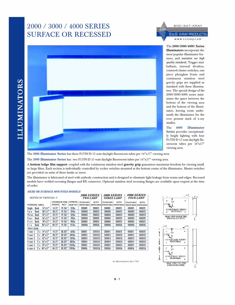
The 2000/3000/4000/ SeriesIlluminators incorporate themost popular illuminator fea-tures, and maintain our highquality standards . Trigger startballasts, internal dividers,centered cluster switches, onepiece plexiglass fronts andcontinuous stainless steelgravity grips are supplied asstandard with these illumina-tors. The special design of the2000/3000/4000 series mini-mizes the space between thebottom of the viewing areaand the bottom of the illumi-nator, leaving room under-neath the illuminator for theever present stack of x-raystudies.
The 4000 IlluminatorSeries provides exceptional-ly bright lighting with fourF15T8/D 15 watt daylight flu-orescent tubes per 14 ” x 17 ”viewing area.
The 3000 Illuminator Series has three F15T8/D 15 watt daylight fluorescent tubes per 14”x17” viewing area.
The 2000 Illuminator Series has two F15T8/D 15 watt daylight fluorescent tubes per 14”x17” viewing area.
A bottom ledge film support coupled with the continuous stainless steel gravity grip guarantees maximum freedom for viewing smallor large films. Each section is individually controlled by rocker switches mounted at the bottom center of the illuminator. Master switchesare provided on units of three banks or more.
The illuminator is fabricated of steel with unibody construction and is designed to eliminate light leakage from seams and edges. Recessedmodels have welded recessing flanges and BX connector. Optional stainless steel recessing flanges are available upon request at the timeof order.
4000 SERIESFOUR LAMP
STANDARD
SWITCHESAUTO
SWITCHES
ALL MEASUREMENTS ARE ± 1/16”
8 0 0 / 3 4 7 - X R AY
S & S X- R AY PR O D UCTSw w w. s s x ra y. c o m
4000 SERIESFOUR LAMP
B - 8
2000 / 3000 / 4000 SERIES
Single Bank 14”x17” 14.75” 19.156” 15 . 2 5” 19 . 656 ” 23 lbsT w o Bank 28”x17” 28.75” 19.156” 29. 2 5” 19 . 656 ” 39lbsTh r e e Bank 42”x17” 42.75” 19.156” 43. 2 5 ” 19 . 656 ” 50 lbsF o u r Bank 56”x17” 56.75” 19.156” 57. 2 5 ” 19 . 656 ” 70 lbsF i v e Bank 70”x17” 70.75” 19.156” 71. 2 5 ” 19 . 656 ” 98 lbsS i x Bank 84”x17” 84.75” 19.156” 85. 2 5 ” 19 . 656 ” 115 lbs
1 over 1 2 x 14”x17” 14.75” 38.312” 15. 2 5 ” 38 . 812” 60 lbs2 over 2 2 x 28”x17” 28.75” 38.312” 29. 2 5 ” 38 . 812” 100lbs3 over 3 2 x 42”x17” 42.75” 38.312” 43. 2 5 ” 38 . 812” 130 lbs4 over 4 2 x 56”x17” 56.75” 38.312” 57. 2 5 ” 38 . 812” 180 lbs5 over 5 2 x 70”x17” 70.75” 38.312” 71. 2 5 ” 38 . 812” 230 lbs6 over 6 2 x 84”x17” 84.75” 38.312” 85. 2 5 ” 38 . 812” 290 lbs
VIEWING AREA
TWO TIER
RECESSED MODELS
WIDTH HGT SHIP WT
EXTERIOR DIM APPROX STANDARD
SWITCHESSTANDARD
SWITCHESAUTO
SWITCHESAUTO
SWITCHES
3000 SERIESTHREE LAMP
2000 SERIESTWO LAMP
WALL OPENING
Finish: White Baked Enamel, Stainless Steel Trim (welded on recessing flanges are white baked enamel) Electrical: Viewers operate on 120 volt, 60 Hz. 2000 Series: .47 amps per section, 3000 series: .61 amps per section, 4000 series: 1.0 amps per section.Surface mounting models are supplied with a 6’ three conductor line cord (see diagram for wiring locations). Recessed models come with BX connectors.For special voltages consult factory.✶ Optional Items: Modular Mobile system (pg B-23), mobile stand, console arms, angulated viewing system (pg B-25) corner modules (pg B-24), hospitalgrade plugs (pg B-30).
STANDARD
SWITCHESAUTO
SWITCHES
2 0 0 0 41 2 0 0 0 61 3 0 0 0 41 3 0 0 0 61 4 0 0 0 41 4 0 0 0 612 0 0 0 42 2 0 0 0 62 3 0 0 0 42 3 0 0 0 62 4 0 0 0 42 4 0 0 0 622 0 0 0 43 2 0 0 0 63 3 0 0 0 43 3 0 0 0 63 4 0 0 0 43 4 0 0 0 6 32 0 0 0 44 2 0 0 0 64 3 0 0 0 44 3 0 0 0 64 4 0 0 0 44 4 0 0 0 6 42 0 0 0 45 2 0 0 0 65 3 0 0 0 45 3 0 0 0 65 4 0 0 0 45 4 0 0 0 652 0 0 0 46 20 0 0 66 3 0 0 0 46 3 0 0 0 66 4 0 0 0 4 6 4 0 0 0 66
2 0 0 051 2 0 0 071 300051 3 0 0 071 4 0 0 051 4 0 0 0712 0 0 052 2 0 0 072 300052 3 0 0 072 4 0 0 052 4 0 0 0722 0 0 053 2 0 0 073 300053 3 0 0 073 4 0 0 053 4 0 0 0732 0 0 054 2 0 0 074 300054 3 0 0 074 4 0 0 054 4 0 0 0742 0 0 055 2 0 0 075 300055 3 0 0 075 4 0 0 055 4 0 0 0752 0 0 056 2 0 0 076 300056 3 0 0 076 4 0 0 056 4 0 0 076
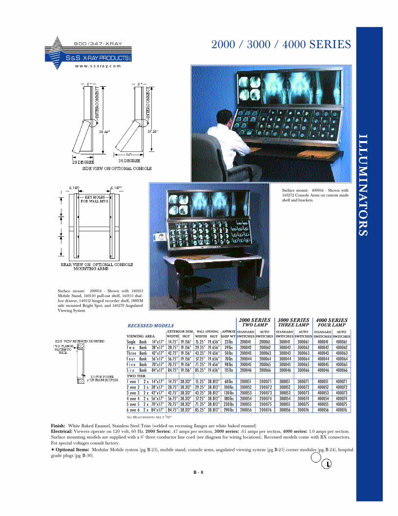
Surface mount: 200014 - Shown with 140103Mobile Stand, 140110 pull-out shelf, 140111 shal -low drawer, 140112 hinged recorder shelf, 188SMside mounted Bright Spot, and 140279 AngulatedViewing System
ALL MEASUREMENTS ARE ± 1/16”
WIDTH HGT
Surface mount: 400014 - Shown with140272 Console Arms on custom madeshelf and brackets.
8 0 0 / 3 4 7 - X R AY
S &S X- R AY PR O D UCTSw w w . s s x ra y. c o m
B - 9
2X SERIES / 4X HI - LOW
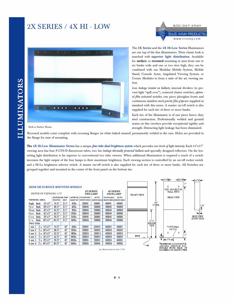
The 2X Series and the 4X Hi-Low Series Illuminatorsare our top of the line illuminators. Their classic look ismatched with superior light distribution. Availablefor surface or recessed mounting in sizes from one tosix banks wide and one or two tiers high, they can becombined with our Modular Mobile System, MobileStand, Console Arms, Angulated Viewing System, orCorner Modules to form a state of the art viewing sta-tion.
Low leakage instant on ballasts, internal dividers (to pre-vent light “spill over”), centered cluster switches, option -al film activated switches, one piece plexiglass fronts andcontinuous stainless steel gravity film grips are supplied asstandard with this series. A master on/off switch is alsosupplied for each tier of three or more banks.
Each tier of the illuminator is of one piece heavy dutysteel construction. Professionally welded and groundseams on this viewbox provide exceptional rigidity andstrength. Distracting light leakage has been eliminated.
Recessed models come complete with recessing flanges (in white baked enamel) permanently welded to the case. Holes are provided inthe flange for ease of mounting.
The 4X Hi-Low Illuminator Series has a unique four tube dual brightness system which provides two levels of light intensity. Each 14”x17”
viewing area has four F15T8/D fluorescent tubes, two low leakage thermally protected ballasts and specially designed reflectors. On the low
setting light distribution is far superior to conventional two tube viewers. When additional illumination is required a touch of a switch
increases the light output of the four lamps to their maximum brightness. Each viewing section is controlled by an on/off rocker switch
and a Hi-Lo brightness selector switch. A master on/off switch is also supplied for each tier of three or more banks. All Switches are
grouped together and mounted in the center of the front panel on the bottom tier.
Single Bank 14”x17” 14.75” 21.5” 30 lbs 2X0041 2X0001 4X0041 4 X 0 0 01T w o Bank 28”x17” 28.75” 21.5” 60 lbs 2X0042 2X0002 4X0042 4X0002T h r e e Bank 42”x17” 42.75” 21.5” 90 lbs 2X0043 2X0003 4X0043 4X0003F o u r Bank 56”x17” 56.75” 21.5” 120lbs 2X0044 2X0004 4X0044 4X0004F i v e Bank 70”x17” 70.75” 21.5” 150 lbs 2X0045 2X0005 4X0045 4X0005S i x Bank 84”x17” 84.75” 21.5” 160 lbs 2X0046 2X0006 4X0046 4X0006
1 over 1 2 x 14”x17” 14.75” 43” 60lbs 2 X 0 051 2 X 0 011 4 X 0 051 4 X 0 0112 over 2 2 x 28”x17” 28.75” 43” 120 lbs 2X0052 2 X 0 012 4 X 0 052 4 X 0 0123 over 3 2 x 42”x17” 42.75” 43” 180 lbs 2X 0 053 2 X 0 013 4 X 0 053 4 X 0 0134 over 4 2 x 56”x17” 56.75” 43” 240 lbs 2X0054 2 X 0 014 4 X 0 054 4 X 0 0145 over 5 2 x 70”x17” 70.75” 43” 300 lbs 2X0055 2X 0 015 4 X 0 055 4 X 0 0156 over 6 2 x 84”x17” 84.75” 43” 360 lbs 2X0056 2 X 0 016 4 X 0 056 4 X 0 016
4X SERIESFOUR LAMP
VIEWING AREASTANDARD
SWITCHESSTANDARD
SWITCHESAUTO
SWITCHESAUTO
SWITCHES
TWO TIER
DESK OR SURFACE MOUNTED MODELS
2X SERIESTWO LAMPDEPTH OF VIEWE RS: 3.75”
WIDTH HGT SHIP WTEXTERIOR DIM APPROX.
Desk or Surface Mount
ALL MEASUREMENTS ARE ± 1/16”
8 0 0 / 3 4 7 - X R AY
S & S X- R AY PR O D UCTSw w w. s s x ra y. c o m
B - 10
2X SERIES / 4X HI - LOW
Finish: White Baked Enamel, Stainless Steel Trim (recessing flanges are white baked enamel)Electrical: Viewers operate on 120 volt, 60 Hz, 1.6 Amps AC per viewing area. Surface mounting models are supplied with a 6’ three conductor linecord (see diagram for wiring locations). Recessed models come with BX connectors. For special voltages consult factory.✶ Optional Items: Modular Mobile system (pg. B-23), mobile stand, console arms, angulated viewing system ( pg. B-25), hinge kits and corner modules( pg. B-24), hospital grade plugs (pg. B-30).
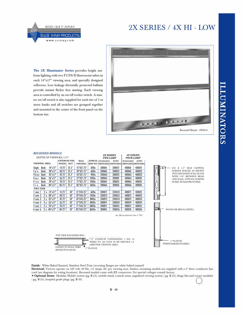
The 2X Illuminator Series provides bright uni-
form lighting with two F15T8/D fluorescent tubes in
each 14”x17” viewing area, and specially designed
reflectors. Low leakage thermally protected ballasts
provide instant flicker free starting. Each viewing
area is controlled by an on/off rocker switch. A mas-
ter on/off switch is also supplied for each tier of 3 or
more banks and all switches are grouped together
and mounted in the center of the front panel on the
bottom tier.
Single Bank 14”x17” 14.75” 21.5” 15 ” X 21 . 75 ” 30lbsT w o Bank 28”x17” 28.75” 21.5” 29”X 21 . 75 ” 60 lbsT h r e e Bank 42”x17” 42.75” 21.5” 43”X 21 . 75 ” 90 lbsF o u r Bank 56”x17” 56.75” 21.5” 57”X 21 . 75 ” 120lbsF i v e Bank 70”x17” 70.75” 21.5” 71”X 21 . 75 ” 150 lbsS i x Bank 84”x17” 84.75” 21.5” 85”X 21 . 75 ” 160 lbs
1 over 1 2 x 14”x17” 14.75” 43” 15 ” X 43 . 2 5 ” 60 lbs2 over 2 2 x 28”x17” 28.75” 43” 29”X 43 . 2 5 ” 120 lbs3 over 3 2 x 42”x17” 42.75” 43” 43”X 43 . 2 5 ” 180 lbs4 over 4 2 x 56”x17” 56.75” 43” 57”X 43 . 2 5 ” 240 lbs5 over 5 2 x 70”x17” 70.75” 43” 71”X 43 . 2 5 ” 300 lbs6 over 6 2 x 84”x17” 84.75” 43” 85”X 43 . 2 5 ” 360 lbs
VIEWING AREA
TWO TIER
RECESSED MODELSDEPTH OF VIEWE RS: 3.75”
WIDTH HGT SHIP WT
EXTERIOR DIM APPROX.
2 X 0 0 61 2 X 0 0 21 4 X 0 0 61 4 X 0 0 212X0062 2X0022 4X0062 4X00222 X 0 0 6 3 2X0023 4X0063 4X00232X0064 2X0024 4X0064 4X00242X0065 2X0025 4X0065 4X00252X0066 2X0026 4X0066 4X0026
2 X 0 071 2 X 0 0 31 4X0071 4 X 0 0 312 X 0 072 2 X 0 0 32 4X0072 4X00322 X 0 073 2 X 0 0 3 3 4X0073 4X00332X0074 2X0034 4 X 0 074 4X00342X0075 2 X 0 0 35 4X0075 4X00352X0076 2 X 0 0 36 4 X 0 076 4X0036
STANDARD
SWITCHESSTANDARD
SWITCHESAUTO
SWITCHESAUTO
SWITCHES
4X SERIESFOUR LAMP
2X SERIESTWO LAMP
WALLOPENING
# 10 X 1.5” SELF TA PPINGSCREWS SPACED AS SHOWNINTO RECESSED WALL PLATEWITH 1/16” BETWEEN HEADAND WALL. I NSTALL SCREWSIN KEY HOLES PROVI DED.
WOOD OR METAL LINTEL
1” FLANGE(WHITE BAKED ENAMEL)
1/2” CONDUIT CON TA INING 3 NO. 14WIRES TO 120 VOLT 60 HZ SERVICE. 1.6AMPS PER VIEWING AREA.
1” FLANGEFASTEN TO WALL THRUHOLES IN FLAN GE
TOP VIEW R ECESSED MTG.
ALL MEASUREMENTS ARE ± 1/16”
Recessed Mount: 4X0034
8 0 0 / 3 4 7 - X R AY
S &S X- R AY PR O D UCTSw w w . s s x ra y. c o m
DELUXE 470 SERIES
B - 11
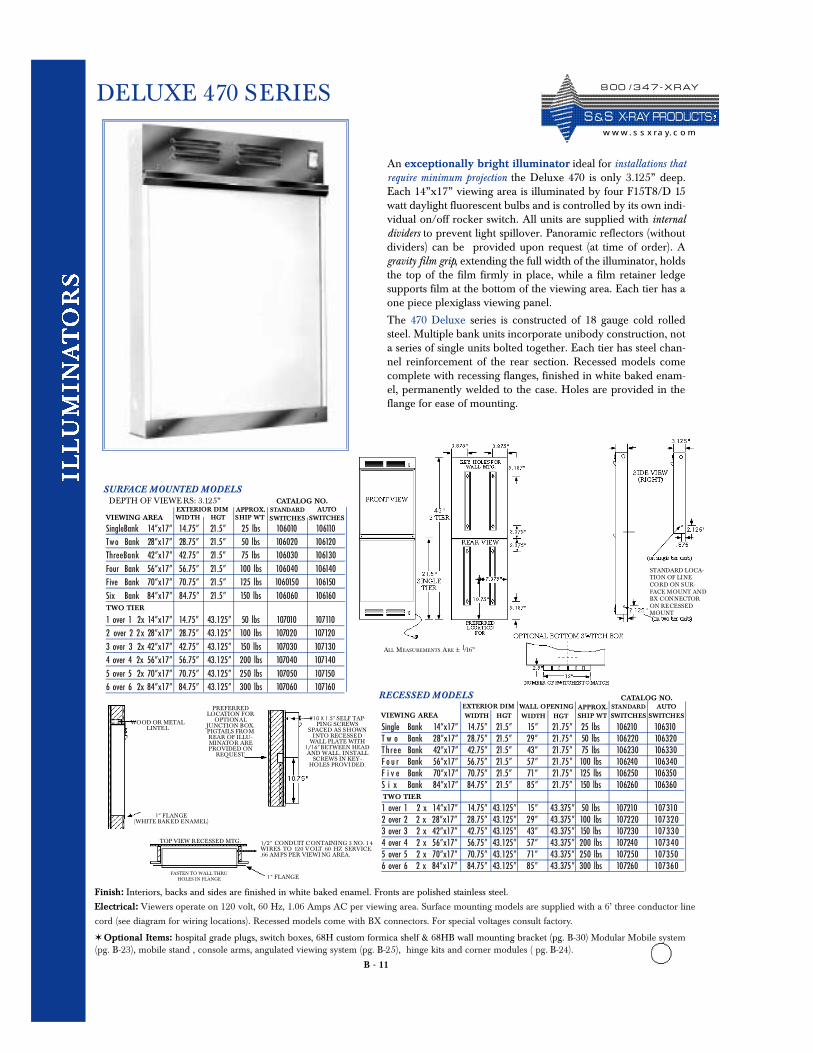
An exceptionally bright illuminator ideal for installations thatrequire minimum projection the Deluxe 470 is only 3.125” deep.Each 14”x17” viewing area is illuminated by four F15T8/D 15watt daylight fluorescent bulbs and is controlled by its own indi-vidual on/off rocker switch. All units are supplied with internaldividers to prevent light spillover. Panoramic reflectors (withoutdividers) can be provided upon request (at time of order). Agravity film grip, extending the full width of the illuminator, holdsthe top of the film firmly in place, while a film retainer ledgesupports film at the bottom of the viewing area. Each tier has aone piece plexiglass viewing panel.
The 470 Deluxe series is constructed of 18 gauge cold rolledsteel. Multiple bank units incorporate unibody construction, nota series of single units bolted together. Each tier has steel chan-nel reinforcement of the rear section. Recessed models comecomplete with recessing flanges, finished in white baked enam-el, permanently welded to the case. Holes are provided in theflange for ease of mounting.
Finish: Interiors, backs and sides are finished in white baked enamel. Fronts are polished stainless steel.
Electrical: Viewers operate on 120 volt, 60 Hz, 1.06 Amps AC per viewing area. Surface mounting models are supplied with a 6’ three conductor line
cord (see diagram for wiring locations). Recessed models come with BX connectors. For special voltages consult factory.
✶ Optional Items: hospital grade plugs, switch boxes, 68H custom formica shelf & 68HB wall mounting bracket (pg. B-30) Modular Mobile system(pg. B-23), mobile stand , console arms, angulated viewing system (pg. B-25), hinge kits and corner modules ( pg. B-24).
SURFACE MOUNTED MODELSDEPTH OF VIEWE RS: 3.125”
SingleBank 14”x17” 14.75” 21.5” 25 lbs 106010 106110Tw o Bank 28”x17” 28.75” 21.5” 50 lbs 106020 106120ThreeBank 42”x17” 42.75” 21.5” 75 lbs 106030 106130Four Bank 56”x17” 56.75” 21.5” 100 lbs 106040 106140Five Bank 70”x17” 70.75” 21.5” 125 lbs 1060150 106150Six Bank 84”x17” 84.75” 21.5” 150 lbs 106060 106160
VIEWING AREA WIDTH HGT SHIP WTEXTERIOR DIM APPROX.
CATALOG NO.
1 over 1 2x 14”x17” 14.75” 43.125” 50 lbs 107010 1071102 over 2 2 x 28”x17” 28.75” 43.125” 100 lbs 107020 1071203 over 3 2x 42”x17” 42.75” 43.125” 150 lbs 107030 1071304 over 4 2x 56”x17” 56.75” 43.125” 200 lbs 107040 1071405 over 5 2x 70”x17” 70.75” 43.125” 250 lbs 107050 1071506 over 6 2x 84”x17” 84.75” 43.125” 300 lbs 107060 107160
TWO TIER
STANDARDSWITCHES
AUTOSWITCHES
Single Bank 14”x17” 14.75” 21.5” 15 ” 21 . 75 ” 25 lbsT w o Bank 28”x17” 28.75” 21.5” 29 ” 21 . 75 ” 50 lbsT h r e e Bank 42”x17” 42.75” 21.5” 43 ” 21 . 75 ” 75 lbsF o u r Bank 56”x17” 56.75” 21.5” 57 ” 21 . 75 ” 100 lbsF i v e Bank 70”x17” 70.75” 21.5” 71 ” 21 . 75 ” 125 lbsS i x Bank 84”x17” 84.75” 21.5” 85 ” 21 . 75 ” 150 lbs
1 over 1 2 x 14”x17” 14.75” 43.125” 15 ” 43 . 375 ” 50 lbs2 over 2 2 x 28”x17” 28.75” 43.125” 29 ” 43 . 375 ” 100 lbs3 over 3 2 x 42”x17” 42.75” 43.125” 43 ” 43 . 375 ” 150 lbs4 over 4 2 x 56”x17” 56.75” 43.125” 57 ” 43 . 375 ” 200 lbs5 over 5 2 x 70”x17” 70.75” 43.125” 71 ” 43 . 375 ” 250 lbs6 over 6 2 x 84”x17” 84.75” 43.125” 85 ” 43 . 375 ” 300 lbs
VIEWING AREA
TWO TIER
RECESSED MODELS
WIDTH HGT SHIP WTEXTERIOR DIM APPROX.
10 6210 10 6 31010 62 2 0 10 6 32 010 62 3 0 10 6 3 3 010 624 0 10 6 3 4 010 62 50 10 6 35010 626 0 10 6 36 0
107210 1073101072 2 0 10732 01072 3 0 1073 3 010724 0 1073 4 01072 50 10735010726 0 10736 0
STANDARD
SWITCHESAUTO
SWITCHESWALL OPENINGWIDTH HGT#10 X 1.5” SELF TAP-
PING SCREWSSPACED AS SHOWN
INTO RECESSEDWALL PLATE WITH
1/16” BETWEEN HEADAND WALL. INSTALL
SCREWS IN KEY-HOLES PROVIDED.
WOOD OR METALLINTEL
1” FLANGE(WHITE BAKED ENAMEL)
1/2” CONDUIT CONTAINING 3 NO. 1 4WIRES TO 120 VOLT 60 HZ SERVICE..66 AMPS PER VIEWI NG AREA.
1” FLANGE
PREFERREDLOCATION FOR
OPTIONALJUNCTION BOX.PIGTAILS FROMREAR OF ILLU-MINATOR AREPROVIDED ON
REQUEST.
TOP VIEW RECESSED MTG.
FASTEN TO WALL THRUHOLES IN FLANGE
CATALOG NO.
ALL MEASUREMENTS ARE ± 1/16”
STANDARD LOCA-TION OF LINECORD ON SUR-FACE MOUNT ANDBX CONNECTORON RECESSEDMOUNT
8 00 / 3 4 7 - X R AY
S &S X- R AY PR O D UCTSw w w . s s x ra y. c o m
B - 12
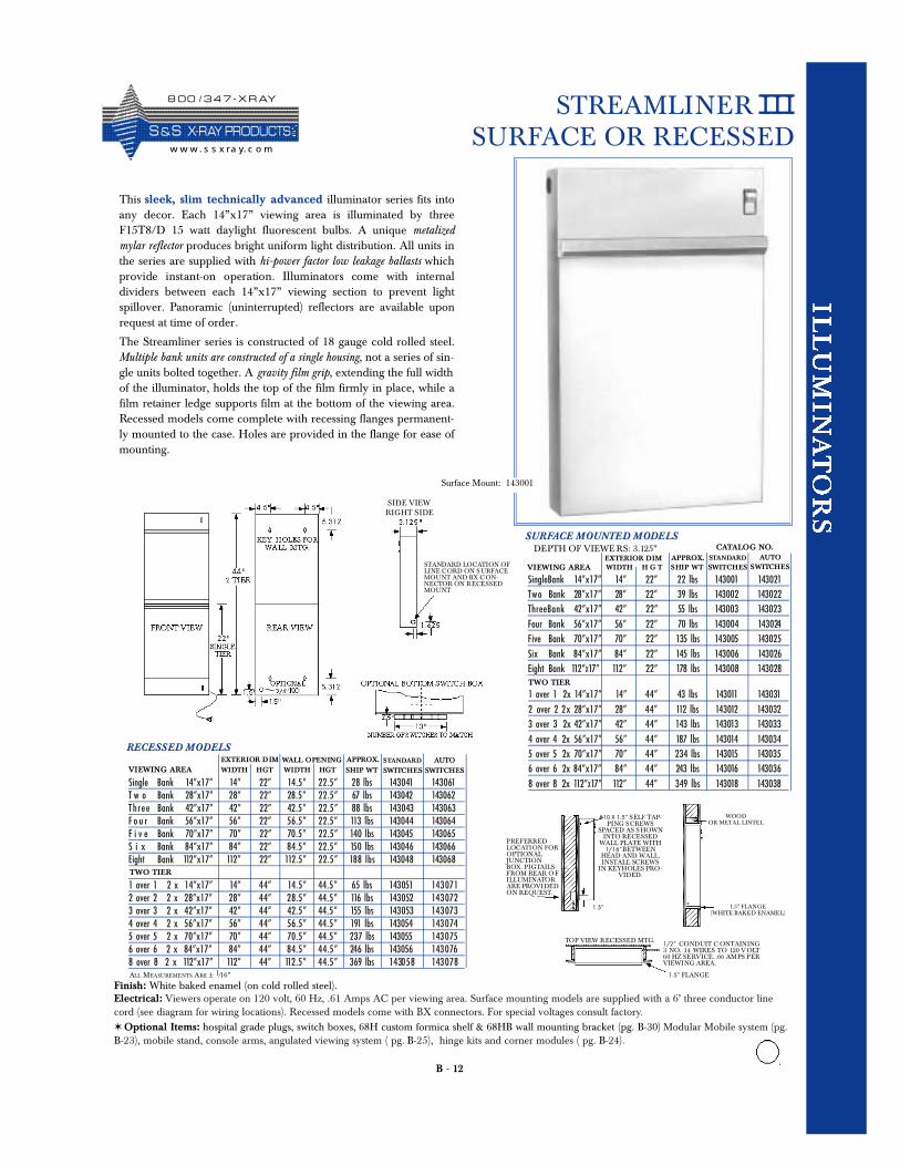
STREAMLINER IIISURFACE OR RECESSED
This sleek, slim technically advanced illuminator series fits intoany decor. Each 14”x17” viewing area is illuminated by threeF15T8/D 15 watt daylight fluorescent bulbs. A unique metalizedmylar reflector produces bright uniform light distribution. All units inthe series are supplied with hi-power factor low leakage ballasts whichprovide instant-on operation. Illuminators come with internaldividers between each 14”x17” viewing section to prevent lightspillover. Panoramic (uninterrupted) reflectors are available uponrequest at time of order.
The Streamliner series is constructed of 18 gauge cold rolled steel.Multiple bank units are constructed of a single housing, not a series of sin-gle units bolted together. A gravity film grip, extending the full widthof the illuminator, holds the top of the film firmly in place, while afilm retainer ledge supports film at the bottom of the viewing area.Recessed models come complete with recessing flanges permanent-ly mounted to the case. Holes are provided in the flange for ease ofmounting.
SURFACE MOUNTED MODELSDEPTH OF VIEWE RS: 3.125”
SingleBank 14”x17” 14” 22” 22 lbs 143001 143021Tw o Bank 28”x17” 28” 22” 39 lbs 143002 143022ThreeBank 42”x17” 42” 22” 55 lbs 143003 143023Four Bank 56”x17” 56” 22” 70 lbs 143004 143024Five Bank 70”x17” 70” 22” 135 lbs 143005 143025Six Bank 84”x17” 84” 22” 145 lbs 143006 143026Eight Bank 112”X17” 112” 22” 178 lbs 143008 143028
VIEWING AREA WIDTH H G T SHIP WTEXTERIOR DIM APPROX.
CATALOG NO.
1 over 1 2x 14”x17” 14” 44” 43 lbs 143011 1430312 over 2 2 x 28”x17” 28” 44” 112 lbs 143012 1430323 over 3 2x 42”x17” 42” 44” 143 lbs 143013 1430334 over 4 2x 56”x17” 56” 44” 187 lbs 143014 1430345 over 5 2x 70”x17” 70” 44” 234 lbs 143015 1430356 over 6 2x 84”x17” 84” 44” 243 lbs 143016 1430368 over 8 2x 112”X17” 112” 44” 349 lbs 143018 143038Single Bank 14”x17” 14” 22” 14 . 5 ” 2 2 . 5 ” 28 lbs
T w o Bank 28”x17” 28” 22” 28 . 5 ” 2 2 . 5 ” 67 lbsTh r e e Bank 42”x17” 42” 22” 42 . 5 ” 2 2 . 5 ” 88 lbsF o u r Bank 56”x17” 56” 22” 56 . 5 ” 2 2 . 5 ” 113 lbsF i v e Bank 70”x17” 70” 22” 70 . 5 ” 2 2 . 5 ” 140 lbsS i x Bank 84”x17” 84” 22” 8 4 . 5 ” 2 2 . 5 ” 150 lbsEight Bank 112”x17” 112” 22” 112 . 5 ” 2 2 . 5 ” 188 lbs
1 over 1 2 x 14”x17” 14” 44” 14 . 5 ” 44 . 5 ” 65 lbs2 over 2 2 x 28”x17” 28” 44” 28 . 5 ” 44 . 5 ” 116 lbs3 over 3 2 x 42”x17” 42” 44” 42 . 5 ” 44 . 5 ” 155 lbs4 over 4 2 x 56”x17” 56” 44” 56 . 5 ” 44 . 5 ” 191 lbs5 over 5 2 x 70”x17” 70” 44” 70 . 5 ” 44 . 5 ” 237 lbs6 over 6 2 x 84”x17” 84” 44” 8 4 . 5 ” 44 . 5 ” 246 lbs8 over 8 2 x 112”x17” 112” 44” 112 . 5 ” 44 . 5” 369 lbs
VIEWING AREA
TWO TIER
RECESSED MODELS
WIDTH HGT SHIP WTEXTERIOR DIM APPROX.
143 0 41 143 0 61143042 143062143 0 43 143063143044 143064143045 143065143046 143066143048 143068
143 051 143 071143 052 143 072143 053 143 073143054 143 074143055 143 075143056 143 076143058 143 078
STANDARD
SWITCHESAUTO
SWITCHESWALL OPENING
TWO TIER
STANDARDSWITCHES
AUTOSWITCHES
WIDTH HGT
Finish: White baked enamel (on cold rolled steel). Electrical: Viewers operate on 120 volt, 60 Hz, .61 Amps AC per viewing area. Surface mounting models are supplied with a 6’ three conductor linecord (see diagram for wiring locations). Recessed models come with BX connectors. For special voltages consult factory.✶ Optional Items: hospital grade plugs, switch boxes, 68H custom formica shelf & 68HB wall mounting bracket (pg. B-30) Modular Mobile system (pg.B-23), mobile stand, console arms, angulated viewing system ( pg. B-25), hinge kits and corner modules ( pg. B-24).
#10 X 1.5” SELF TAP-PING SCREWS
SPACED AS S HOWNINTO RECESSED
WALL PLATE WITH1/16”BETWEEN
HEAD AND WALL.INSTALL SCREWS
IN KEYHOLES PRO-VIDED.
WOODOR METAL LINTEL
1.5” FLANGE(WHITE BAKED ENAMEL)
1/2” CONDUIT C ONTAINING3 NO. 14 WIRES TO 120 V OLT60 HZ SERVICE. .66 AMPS PERVIEWING AREA.
1.5” FLANGE
PREFERREDLOCATION FOROPTIONALJUNCTIONBOX. PIGTAILSFROM REAR O FILLUMINATORARE PROVIDEDON REQUEST.
STANDARD LOCATION OFLINE CORD ON S URFACEMOUNT AND BX C ON-NECTOR ON RECESSEDMOUNT
1.5”
TOP VIEW RECESSED MTG.
SIDE VIEWRIGHT SIDE
ALL MEASUREMENTS ARE ± 1/16”
Surface Mount: 143001
8 0 0 / 3 4 7 - X R AY
S &S X- R AY PR O D UCTSw w w . s s x ra y. c o m
B - 13
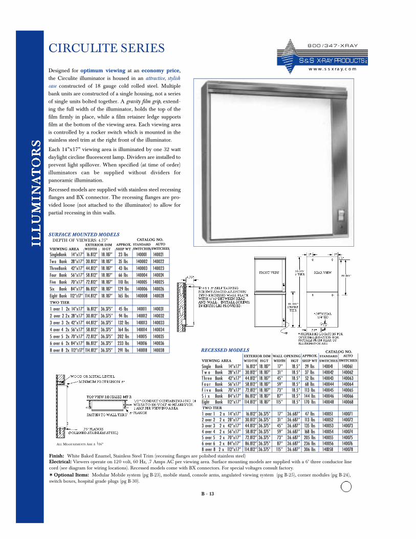
CIRCULITE SERIES
Designed for optimum viewing at an economy price,the Circulite illuminator is housed in an attractive, stylishcase constructed of 18 gauge cold rolled steel. Multiplebank units are constructed of a single housing, not a seriesof single units bolted together. A gravity film grip, extend-ing the full width of the illuminator, holds the top of thefilm firmly in place, while a film retainer ledge supportsfilm at the bottom of the viewing area. Each viewing areais controlled by a rocker switch which is mounted in thestainless steel trim at the right front of the illuminator.
Each 14”x17” viewing area is illuminated by one 32 wattdaylight circline fluorescent lamp. Dividers are installed toprevent light spillover. When specified (at time of order)illuminators can be supplied without dividers forpanoramic illumination.
Recessed models are supplied with stainless steel recessingflanges and BX connector. The recessing flanges are pro-vided loose (not attached to the illuminator) to allow forpartial recessing in thin walls.
SURFACE MOUNTED MODELSDEPTH OF VIEWERS: 4.75”
SingleBank 14”x17” 16.812” 18.187” 23 lbs 140001 140021Tw o Bank 28”x17” 30.812” 18.187” 35 lbs 140002 140022ThreeBank 42”x17” 44.812” 18.187” 43 lbs 140003 140023Four Bank 56”x17” 58.812” 18.187” 66 lbs 140004 140024Five Bank 70”x17” 72.812” 18.187” 110 lbs 140005 140025Six Bank 84”x17” 86.812” 18.187” 129 lbs 140006 140026Eight Bank 112”X17” 114.812” 18.187” 165 lbs 140008 140028
VIEWING AREA WIDTH HGT SHIP WTEXTERIOR DIM APPROX.
CATALOG NO.
1 over 1 2x 14”x17” 16.812” 36.375” 45 lbs 140011 1400312 over 2 2 x 28”x17” 30.812” 36.375” 94 lbs 140012 1400323 over 3 2x 42”x17” 44.812” 36.375” 132 lbs 140013 1400334 over 4 2x 56”x17” 58.812” 36.375” 164 lbs 140014 1400345 over 5 2x 70”x17” 72.812” 36.375” 202 lbs 140015 1400356 over 6 2x 84”x17” 86.812” 36.375” 233 lbs 140016 1400368 over 8 2x 112”X17” 114.812” 36.375” 291 lbs 140018 140038
Single Bank 14”x17” 16.812” 18.187” 17 ” 18 . 5 ” 29 lbsT w o Bank 28”x17” 30.812” 18.187” 31 ” 18 . 5 ” 37 lbsT h r e e Bank 42”x17” 44.812” 18.187” 45 ” 18 . 5 ” 52 lbsF o u r Bank 56”x17” 58.812” 18.187” 59 ” 18 . 5 ” 68 lbsF i v e Bank 70”x17” 72.812” 18.187” 73 ” 18 . 5 ” 113 lbsS i x Bank 84”x17” 86.812” 18.187” 87 ” 18 . 5 ” 144 lbsEight Bank 112”x17” 114.812” 18.187” 115 ” 18 . 5 ” 170 lbs
1 over 1 2 x 14”x17” 16.812” 36.375” 17 ” 36 . 687 ” 47 lbs2 over 2 2 x 28”x17” 30.812” 36.375” 31 ” 36 . 687 ” 113 lbs3 over 3 2 x 42”x17” 44.812” 36.375” 45 ” 36 . 687 ” 135 lbs4 over 4 2 x 56”x17” 58.812” 36.375” 59 ” 36 . 687 ” 168 lbs5 over 5 2 x 70”x17” 72.812” 36.375” 73 ” 36 . 687 ” 205 lbs6 over 6 2 x 84”x17” 86.812” 36.375” 87 ” 36 . 687 ” 236 lbs8 over 8 2 x 112”x17” 114.812” 36.375” 115 ” 36 . 687” 306 lbs
VIEWING AREA
TWO TIER
RECESSED MODELS
WIDT H HGT SHIP WTEXTERIOR DIM APPROX.
140041 140061140042 140062140043 140063140044 140064140045 140065140046 140066140048 140068
140051 140071140052 140072140053 140073140054 140074140055 140075140056 140076140058 140078
STANDARD
SWITCHES
AUTOSWITCHES
WALL OPENING
TWO TIER
STANDARDSWITCHES
AUTOSWITCHES
WIDTH HGT
Finish: White Baked Enamel, Stainless Steel Trim (recessing flanges are polished stainless steel) Electrical: Viewers operate on 120 volt, 60 Hz, .7 Amps AC per viewing area. Surface mounting models are supplied with a 6’ three conductor linecord (see diagram for wiring locations). Recessed models come with BX connectors. For special voltages consult factory.✶ Optional Items: Modular Mobile system (pg B-23), mobile stand, console arms, angulated viewing system (pg B-25), corner modules (pg B-24),switch boxes, hospital grade plugs (pg B-30).
CATALOG NO.
ALL MEASUREMENTS ARE ± 1/16”
8 0 0 / 3 4 7 - X R AY
S & S X- R AY PR O D UCTSw w w. s s x ra y. c o m
B - 14
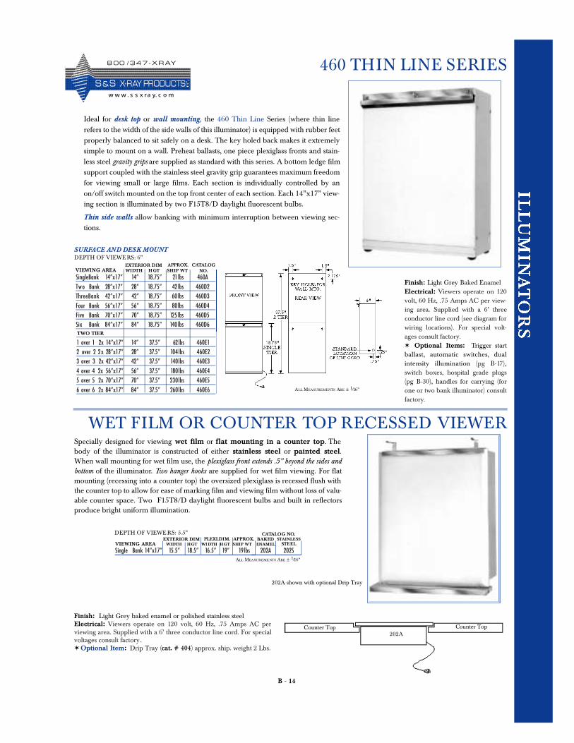
460 THIN LINE SERIES
Ideal for desk top or wall mounting, the 460 Thin Line Series (where thin linerefers to the width of the side walls of this illuminator) is equipped with rubber feetproperly balanced to sit safely on a desk. The key holed back makes it extremelysimple to mount on a wall. Preheat ballasts, one piece plexiglass fronts and stain-less steel gravity grips are supplied as standard with this series. A bottom ledge filmsupport coupled with the stainless steel gravity grip guarantees maximum freedomfor viewing small or large films. Each section is individually controlled by anon/off switch mounted on the top front center of each section. Each 14”x17” view-ing section is illuminated by two F15T8/D daylight fluorescent bulbs.
Thin side walls allow banking with minimum interruption between viewing sec-tions.
Finish: Light Grey Baked EnamelElectrical: Viewers operate on 120volt, 60 Hz, .75 Amps AC per view-ing area. Supplied with a 6’ threeconductor line cord (see diagram forwiring locations). For special volt-ages consult factory.✶ Optional Items: Trigger startballast, automatic switches, dualintensity illumination (pg B-17 ),switch boxes, hospital grade plugs(pg B-30), handles for carrying (forone or two bank illuminator) consultfactory.
SURFACE AND DESK MOUNTDEPTH OF VIEWE RS: 6”
SingleBank 14”x17” 14” 18.75” 21 lbs 460ATw o Bank 28”x17” 28” 18.75” 42 lbs 460D2ThreeBank 42”x17” 42” 18.75” 60 lbs 460D3Four Bank 56”x17” 56” 18.75” 80lbs 460D4Five Bank 70”x17” 70” 18.75” 125 lbs 460D5Six Bank 84”x17” 84” 18.75” 140 lbs 460D6
VIEWING AREA WIDTH H GT SHIP WTEXTERIOR DIM APPROX. CATALOG
NO.
1 over 1 2x 14”x17” 14” 37.5” 62 lbs 460E12 over 2 2 x 28”x17” 28” 37.5” 104 lbs 460E23 over 3 2x 42”x17” 42” 37.5” 140lbs 460E34 over 4 2x 56”x17” 56” 37.5” 180lbs 460E45 over 5 2x 70”x17” 70” 37.5” 230lbs 460E56 over 6 2x 84”x17” 84” 37.5” 260lbs 460E6
TWO TIER
Specially designed for viewing wet film or flat mounting in a counter top. Thebody of the illuminator is constructed of either stainless steel or painted steel.When wall mounting for wet film use, the plexiglass front extends .5” beyond the sides andbottom of the illuminator. Two hanger hooks are supplied for wet film viewing. For flatmounting (recessing into a counter top) the oversized plexiglass is recessed flush withthe counter top to allow for ease of marking film and viewing film without loss of valu-able counter space. Two F15T8/D daylight fluorescent bulbs and built in reflectorsproduce bright uniform illumination.
Finish: Light Grey baked enamel or polished stainless steelElectrical: Viewers operate on 120 volt, 60 Hz, .75 Amps AC perviewing area. Supplied with a 6’ three conductor line cord. For specialvoltages consult factory.✶ Optional Item: Drip Tray (cat. # 404) approx. ship. weight 2 Lbs.
Single Bank 14”x17” 15.5” 18.5” 16.5” 19” 19 lbs 202A 202S
EXTERIOR DIM APPROX.CATALOG NO.
BAKEDENAMEL
STAINLESSSTEELVIEWING AREA WIDTH HGT WI DTH HGT SHIP WT
PLEXI.DIM.DEPTH OF VIEWE RS: 5.5”
Counter Top
WET FILM OR COUNTER TOP RECESSED VIEWER
202A shown with optional Drip Tray
ALL MEASUREMENTS ARE ± 1/16”
ALL MEASUREMENTS ARE ± 1/16”
Counter Top202A
8 0 0 / 3 4 7 - X R AY
S &S X- R AY PR O D UCTSw w w . s s x ra y. c o m
B - 15
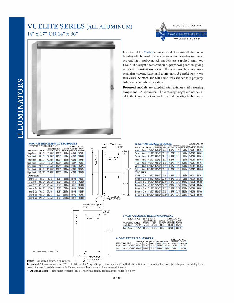
VUELITE SERIES (ALL ALUMINUM)14” x 17” OR 14” x 36”
Each tier of the Vuelite is constructed of an overall aluminumhousing with internal dividers between each viewing section toprevent light spillover. All models are supplied with twoF15T8/D daylight fluorescent bulbs per viewing section, givinguniform illumination, an on/off rocker switch, a one pieceplexiglass viewing panel and a one piece full width gravity gripfilm holder. Surface models come with rubber feet properlybalanced to sit safely on a desk.
Recessed models are supplied with stainless steel recessingflanges and BX connector. The recessing flanges are not weld-ed to the illuminator to allow for partial recessing in thin walls.
Finish: Anodized brushed aluminumElectrical: Viewers operate on 120 volt, 60 Hz, .75 Amps AC per viewing area. Supplied with a 6’ three conductor line cord (see diagram for wiring loca-tions). Recessed models come with BX connectors. For special voltages consult factory.✶ Optional Items: automatic switches (pg. B-17) switch boxes, hospital grade plugs (pg B-30).
14”x17” SURFACE MOUNTED MODELSDEPTH OF VIEWE RS: 5”
SingleBank 14”x17” 15.563” 18.75” 20lbs 145001 145021Tw o Bank 28”x17” 29.563” 18.75” 40 lbs 145002 145022Three Bank 42”x17” 43.563” 18.75” 60lbs 145003 145023Four Bank 56”x17” 57.563” 18.75” 80 lbs 145004 145024Five Bank 70”x17” 71.563” 18.75” 100lbs 145005 145025Six Bank 84”x17” 85.563” 18.75” 120lbs 145006 145026Eight Bank 112”X17” 113.563” 18.75” 160lbs 145008 145028
EXTERIOR DIM APPROX.CATALOG NO.
1 over 1 2x 14”x17” 15.563” 37.5” 50lbs 145011 1450312 over 2 2 x 28”x17” 29.563” 37.5” 90lbs 145012 1450323 over 3 2x 42”x17” 43.563” 37.5” 140lbs 145013 1450334 over 4 2x 56”x17” 57.563” 37.5” 180lbs 145014 1450345 over 5 2x 70”x17” 71.563” 37.5” 230lbs 145015 1450356 over 6 2x 84”x17” 85.563” 37.5” 280lbs 145016 1450368 over 8 2x 112”x17” 113.563” 37.5” 380 lbs 145018 145038
TWO TIER
STANDARD AUTOVIEWING AREA WIDTH H GT SHIP WT SWITCH SWITCH Single Bank 14”x17” 15.563” 18.75” 15.875” 19” 20 lbs
T w o Bank 28”x17” 29.563” 18.75” 29 . 875 ” 19” 40 lbsTh r e e Bank 42”x17” 43.563” 18.75” 43.875” 19” 60lbsF o u r Bank 56”x17” 57.563” 18.75” 57.875” 19” 80lbsF i v e Bank 70”x17” 71.563” 18.75” 71.875” 19” 100 lbsS i x Bank 84”x17” 85.563” 18.75” 85.875” 19” 120 lbsEight Bank 112”x17” 113.563” 18.75” 113.875” 19” 160 l b s
1 over 1 2 x 14”x17” 15.563” 37.75” 15.875” 37. 75 ” 50 lbs2 over 2 2 x 28”x17” 29.563” 37.75” 29.875” 37. 75 ” 90 lbs3 over 3 2 x 42”x17” 43.563” 37.75” 43.875” 37. 75 ” 140lbs4 over 4 2 x 56”x17” 57.563” 37.75” 57.875” 37. 75 ” 180lbs5 over 5 2 x 70”x17” 71.563” 37.75” 71.875” 37. 75 ” 230lbs6 over 6 2 x 84”x17” 85.563” 37.75” 85.875” 37. 75 ” 280lbs8 over 8 2 x 112”x17” 113.563” 37.75” 113.875” 37. 75” 380lbs
TWO TIER
145041 145061145042 145062145043 145063145044 145064145045 145065145046 145066145048 145068
145051 145071145052 145072145053 145073145054 145074145055 145075145056 145076145058 145078
14”x17” RECESSED MODELSEXTERIOR DIM APPROX.
CATALOG NO.STANDARD AUTO
VIEWING AREA WIDTH HGT WI DTH HGT SHIP WT SWITCH SWITCHWALL OPENING
14”x36” SURFACE MOUNTED MODELSDEPTH OF VIEWE RS: 5”
SingleBank 14”x36” 15.563” 37.563” 40lbs 145101 145121Two Bank 28”x36” 29.563” 37.563” 75lbs 145102 145122
EXTERIOR DIM APPROX STANDARD
VIEWING AREA WIDTH HGT SHIP WT SWITCH SWITCH
Single Bank 14”x36” 15.563” 37.563” 15.813” 37.813” 40 lbsTwo Bank 28”x36” 29.563” 37.563” 29.813” 37.813” 75lbs
145111 145161145112 145162
14”x36” REC ESSED MODELSEXTERIOR DIM APPROX. STANDARD
VIEWING AREA WIDTH H GT WI DTH HGT SHIP WT SWITCH SWITCHWALL OPENING
ALL MEASUREMENTS ARE ± 1/16”
CATALOG NO.AUTO
CATALOG NO.AUTO
8 0 0 / 3 4 7 - X R AY
S & S X- R AY PR O D UCTSw w w. s s x ra y. c o m
B - 16
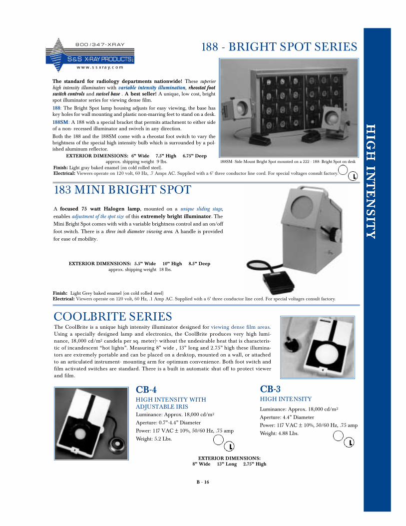
183 MINI BRIGHT SPOT
188 - BRIGHT SPOT SERIES
The standard for radiology departments nationwide! These superiorhigh intensity illuminators with variable intensity illumination, rheostat footswitch controls and swivel base . A best seller! A unique, low cost, brightspot illuminator series for viewing dense film.
188: The Bright Spot lamp housing adjusts for easy viewing, the base haskey holes for wall mounting and plastic non-marring feet to stand on a desk.
188SM: A 188 with a special bracket that permits attachment to either sideof a non- recessed illuminator and swivels in any direction.
Both the 188 and the 188SM come with a rheostat foot switch to vary thebrightness of the special high intensity bulb which is surrounded by a pol-ished aluminum reflector.
188SM- Side Mount Bright Spot mounted on a 222 - 188- Bright Spot on desk
Finish: Light gray baked enamel (on cold rolled steel). Electrical: Viewers operate on 120 volt, 60 Hz, .7 Amps AC. Supplied with a 6’ three conductor line cord. For special voltages consult factory.
EXTERIOR DIMENSIONS: 6” Wide 7.5” High 6.75” Deepapprox. shipping weight 9 lbs.
EXTERIOR DIMENSIONS:8” Wide 13” Long 2.75” High
A focused 75 watt Halogen lamp, mounted on a unique sliding stage,enables adjustment of the spot size of this extremely bright illuminator. TheMini Bright Spot comes with with a variable brightness control and an on/offfoot switch. There is a three inch diameter viewing area. A handle is providedfor ease of mobility.
Finish: Light Grey baked enamel (on cold rolled steel) Electrical: Viewers operate on 120 volt, 60 Hz, .1 Amp AC. Supplied with a 6’ three conductor line cord. For special voltages consult factory.
EXTERIOR DIMENSIONS: 5.5” Wide 10” High 8.5” Deep approx. shipping weight 18 lbs.
COOLBRITE SERIESThe CoolBrite is a unique high intensity illuminator designed for viewing dense film areas.Using a specially designed lamp and electronics, the CoolBrite produces very high lumi-nance, 18,000 cd/m2 candela per sq. meter), without the undesirable heat that is ch a r a c t e r i s-tic of incandescent “hot lights”. Measuring 8” wide , 13” long and 2.75” high these illumina-tors are extremely portable and can be placed on a desktop, mounted on a wall, or attach e dto an articulated instrument- mounting arm for optimum convenience. Both foot switch andfilm activated switches are standard. There is a built in automatic shut off to protect viewerand film.
Luminance: Approx. 18,000 cd/m2
Aperture: 4.4” Diameter
Power: 117 VAC ± 10%, 50/60 Hz, .75 amp
Weight: 4.88 Lbs.
Luminance: Approx. 18,000 cd/m2
Aperture: 0.7”-4.4” Diameter
Power: 117 VAC ± 10%, 50/60 Hz, .75 amp
Weight: 5.2 Lbs.
CB-3HIGH INTENSITY
CB-4HIGH INTENSITY WITHADJUSTABLE IRIS
8 0 0 / 3 4 7 - X R AY
S &S X- R AY PR O D UCTSw w w . s s x ra y. c o m
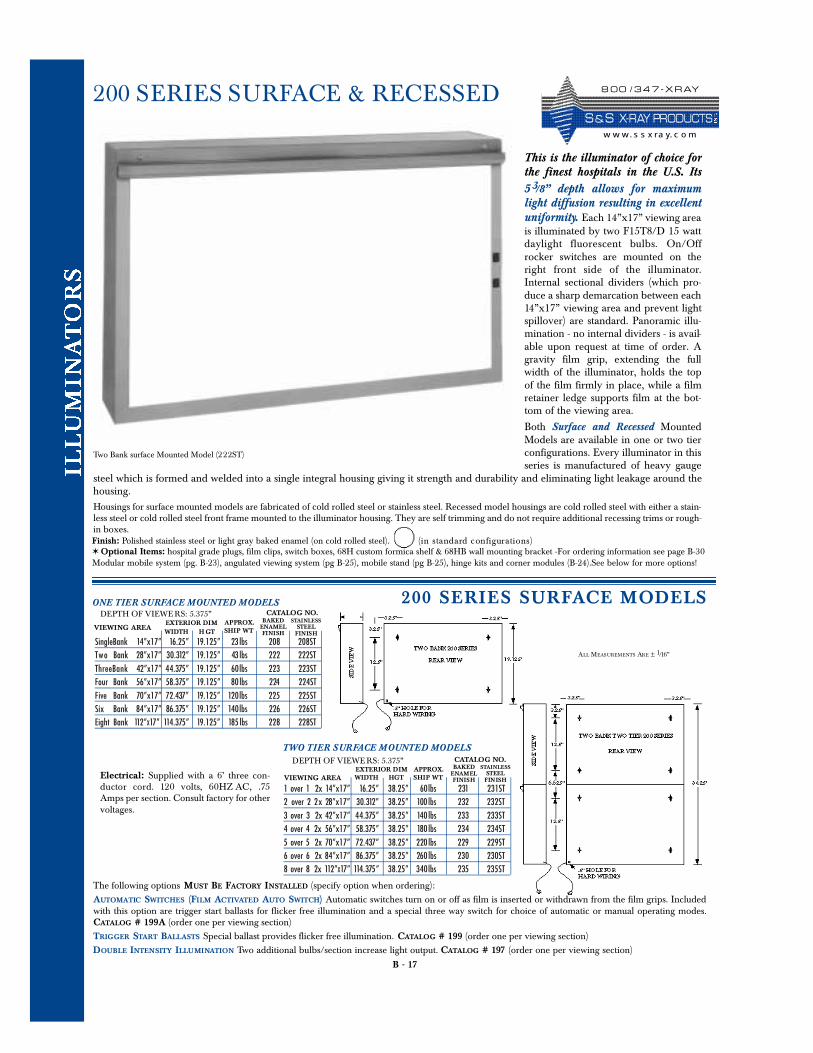
This is the illuminator of choice forthe finest hospitals in the U.S. Its5 3/8” depth allows for maximumlight diffusion resulting in excellentuniformity. Each 14”x17” viewing areais illuminated by two F15T8/D 15 wattdaylight fluorescent bulbs. On/Offrocker switches are mounted on theright front side of the illuminator.Internal sectional dividers (which pro-duce a sharp demarcation between each14”x17” viewing area and prevent lightspillover) are standard. Panoramic illu-mination - no internal dividers - is avail-able upon request at time of order. Agravity film grip, extending the fullwidth of the illuminator, holds the topof the film firmly in place, while a filmretainer ledge supports film at the bot-tom of the viewing area.
Both Surface and Recessed MountedModels are available in one or two tierconfigurations. Every illuminator in thisseries is manufactured of heavy gauge
steel which is formed and welded into a single integral housing giving it strength and durability and eliminating light leakage around thehousing. Housings for surface mounted models are fabricated of cold rolled steel or stainless steel. Recessed model housings are cold rolled steel with either a stain-less steel or cold rolled steel front frame mounted to the illuminator housing. They are self trimming and do not require additional recessing trims or rough-in boxes.
B - 17
200 SERIES SURFACE & RECESSED
Finish: Polished stainless steel or light gray baked enamel (on cold rolled steel). (in standard configurations)✶ Optional Items: hospital grade plugs, film clips, switch boxes, 68H custom formica shelf & 68HB wall mounting bracket -For ordering information see page B-30Modular mobile system (pg. B-23), angulated viewing system (pg B-25), mobile stand (pg B-25), hinge kits and corner modules (B-24).See below for more options!
TWO TIER SURFACE MOUNTED MODELS
ONE TIER SURFACE MOUNTED MODELSDEPTH OF VIEWE RS: 5.375”
SingleBank 14”x17” 16.25” 19.125” 23 lbs 208 208STTw o Bank 28”x17” 30.312” 19.125” 43 lbs 222 222STThreeBank 42”x17” 44.375” 19.125” 60lbs 223 223STFour Bank 56”x17” 58.375” 19.125” 80 lbs 224 224STFive Bank 70”x17” 72.437” 19.125” 120lbs 225 225STSix Bank 84”x17” 86.375” 19.125” 140lbs 226 226STEight Bank 112”X17” 114.375” 19.125” 185 lbs 228 228ST
VIEWING AREAWIDTH H GT SHIP WT
BAKEDENAMELFINISH
STAINLESSSTEELFINISH
EXTERIOR DIM APPROX.CATALOG NO.
DEPTH OF VIEWE RS: 5.375”
1 over 1 2x 14”x17” 16.25” 38.25” 60lbs 231 231ST2 over 2 2 x 28”x17” 30.312” 38.25” 100 lbs 232 232ST3 over 3 2x 42”x17” 44.375” 38.25” 140 lbs 233 233ST4 over 4 2x 56”x17” 58.375” 38.25” 180 lbs 234 234ST5 over 5 2x 70”x17” 72.437” 38.25” 220 lbs 229 229ST6 over 6 2x 84”x17” 86.375” 38.25” 260 lbs 230 230ST8 over 8 2x 112”X17” 114.375” 38.25” 340lbs 235 235ST
VIEWING AREA WIDTH HGT SHIP WT
BAKEDENAMELFINISH
STAINLESSSTEELFINISH
EXTERIOR DIM APPROX.CATALOG NO.
Electrical: Supplied with a 6’ three con-ductor cord. 120 volts, 60 HZ AC, .75Amps per section. Consult factory for othervoltages.
Two Bank surface Mounted Model (222ST)
200 SERIES SURFACE MODEL S
ALL MEASUREMENTS ARE ± 1/16”
The following options MUST BE FACTORY INSTALLED (specify option when ordering):AUTOMATIC SWITCHES (FILM ACTIVATED AUTO SWITCH) Automatic switches turn on or off as film is inserted or withdrawn from the film grips. Includedwith this option are trigger start ballasts for flicker free illumination and a special three way switch for choice of automatic or manual operating modes.CATALOG # 199A (order one per viewing section)TRIGGER START BALLASTS Special ballast provides flicker free illumination. CATALOG # 199 (order one per viewing section)DOUBLE INTENSITY ILLUMINATION Two additional bulbs/section increase light output. CATALOG # 197 (order one per viewing section)
8 0 0 / 3 4 7 - X R AY
S & S X- R AY PR O D UCTSw w w. s s x ra y. c o m
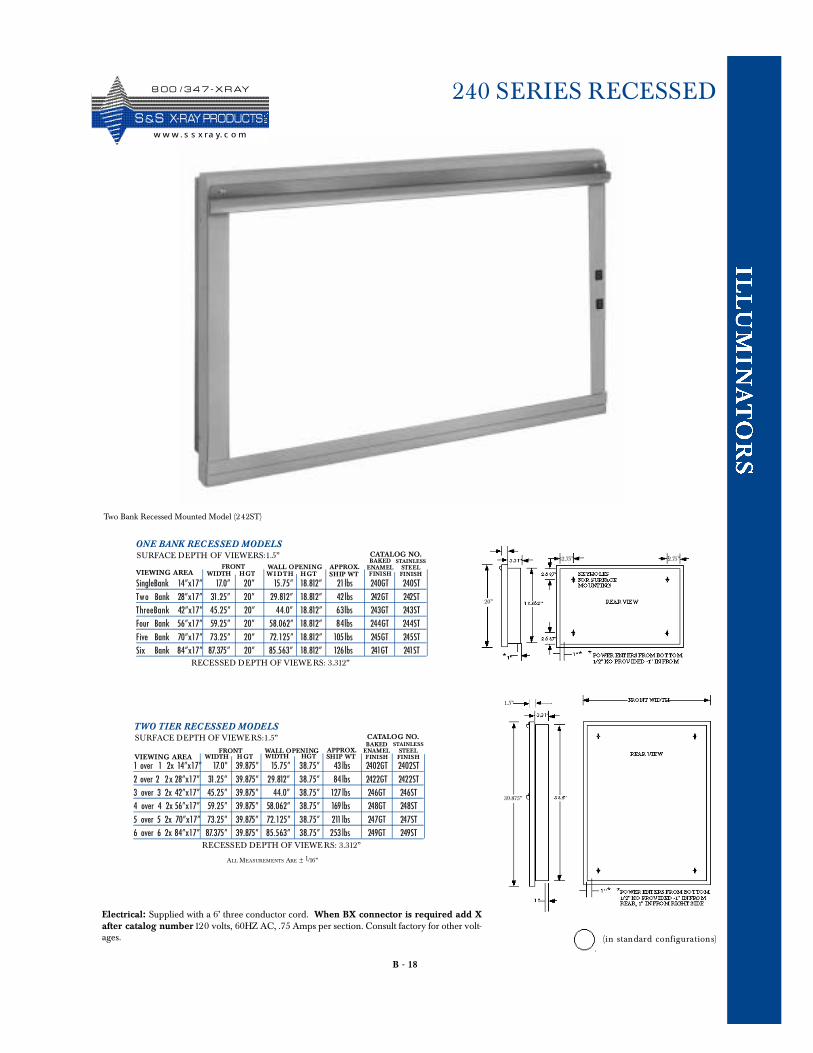
B - 18
240 SERIES RECESSED
ONE BANK REC ESSED MODELSSURFACE DEPTH OF VIEWERS:1.5”
SingleBank 14”x17” 17.0” 20” 15.75” 18.812” 21lbs 240GT 240STTw o Bank 28”x17” 31.25” 20” 29.812” 18.812” 42lbs 242GT 242STThreeBank 42”x17” 45.25” 20” 44.0” 18.812” 63lbs 243GT 243STFour Bank 56”x17” 59.25” 20” 58.062” 18.812” 84lbs 244GT 244STFive Bank 70”x17” 73.25” 20” 72.125” 18.812” 105lbs 245GT 245STSix Bank 84”x17” 87.375” 20” 85.563” 18.812” 126lbs 241GT 241ST
VIEWING AREA WIDTH HGT SHIP WT
BAKEDENAMELFINISH
STAINLESSSTEELFINISH
FRONT APPROX.
CATALOG NO.
W I DT H HGTWALL OPENING
RECESSED DEPTH OF VIEWE RS: 3.312”
TWO TIER RECESSED MODELSSURFACE DEPTH OF VIEWE RS:1.5”
1 over 1 2x 14”x17” 17.0” 39.875” 15.75” 38.75” 43 lbs 2402GT 2402ST2 over 2 2 x 28”x17” 31.25” 39.875” 29.812” 38.75” 84 lbs 2422GT 2422ST3 over 3 2x 42”x17” 45.25” 39.875” 44.0” 38.75” 127 lbs 246GT 246ST4 over 4 2x 56”x17” 59.25” 39.875” 58.062” 38.75” 169 lbs 248GT 248ST5 over 5 2x 70”x17” 73.25” 39.875” 72.125” 38.75” 211 lbs 247GT 247ST6 over 6 2x 84”x17” 87.375” 39.875” 85.563” 38.75” 253 lbs 249GT 249ST
VIEWING AREA WIDTH H GT SHIP WT
BAKEDENAMELFINISH
STAINLESSSTEELFINISH
FRONT APPROX.
CATALOG NO.
WIDTH HGTWALL OPENING
RECESSED DEPTH OF VIEWE RS: 3.312”
Electrical: Supplied with a 6’ three conductor cord. When BX connector is required add Xafter catalog number120 volts, 60HZ AC, .75 Amps per section. Consult factory for other volt-ages.
2.75” 2.75”
ALL MEASUREMENTS ARE ± 1/16”
20”
39.875”
Two Bank Recessed Mounted Model (242ST)
1.5”
(in standard configurations)
8 0 0 / 3 4 7 - X R AY
S &S X- R AY PR O D UCTSw w w . s s x ra y. c o m
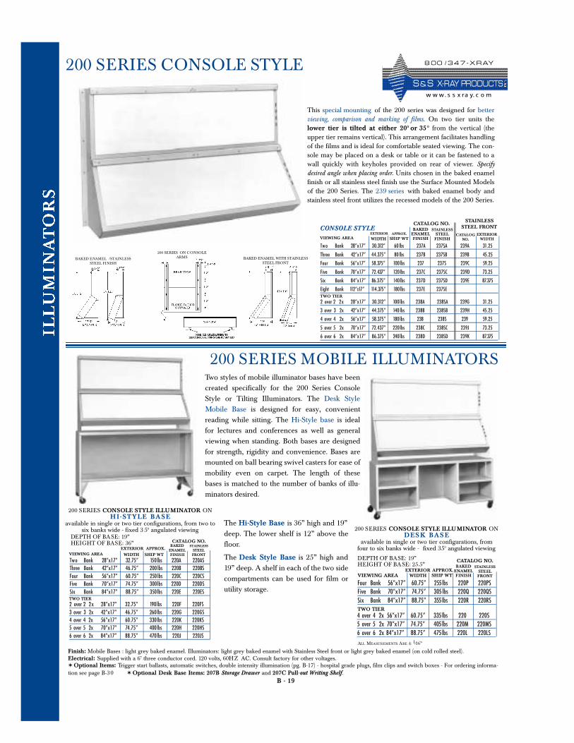
Two styles of mobile illuminator bases have beencreated specifically for the 200 Series ConsoleStyle or Tilting Illuminators. The Desk StyleMobile Base is designed for easy, convenientreading while sitting. The Hi-Style base is idealfor lectures and conferences as well as generalviewing when standing. Both bases are designedfor strength, rigidity and convenience. Bases aremounted on ball bearing swivel casters for ease ofmobility even on carpet. The length of thesebases is matched to the number of banks of illu-minators desired.
B - 19
200 SERIES CONSOLE STYLE
Finish: Mobile Bases : light grey baked enamel. Illuminators: light grey baked enamel with Stainless Steel front or light grey baked enamel (on cold rolled steel).Electrical: Supplied with a 6’ three conductor cord. 120 volts, 60HZ AC. Consult factory for other voltages. ✶ Optional Items: Trigger start ballasts, automatic switches, double intensity illumination (pg. B-17) - hospital grade plugs, film clips and switch boxes - For ordering informa-tion see page B-30 ✶ Optional Desk Base Items: 207B Storage Drawer and 207C Pull-out Writing Shelf.
200 SERIES CONSOLE STYLE ILLUMINATOR ONHI - STYLE BA SE
available in single or two tier configurations, from two to six banks wide - fixed 3 50 angulated viewing
Tw o Bank 28”x17” 32.75” 150lbs 220A 220ASThree Bank 42”x17” 46.75” 200 lbs 220B 220BSFour Bank 56”x17” 60.75” 250 lbs 220C 220CSFive Bank 70”x17” 74.75” 300lbs 220D 220DSSix Bank 84”x17” 88.75” 350lbs 220E 220ES
VIEWING AREA WIDTH SHIP WT
BAKEDENAMELFINISH
STAINLESSSTEELFRONT
EXTERIOR APPROX.
CATALOG NO.
2 over 2 2 x 28”x17” 32.75” 190lbs 220F 220FS3 over 3 2x 42”x17” 46.75” 260lbs 220G 220GS4 over 4 2x 56”x17” 60.75” 330lbs 220K 220KS5 over 5 2x 70”x17” 74.75” 400lbs 220H 220HS6 over 6 2x 84”x17” 88.75” 470lbs 220J 220JS
TWO TIER
DEPTH OF BASE: 19”HEIGHT OF BASE: 36”
200 SERIES CONSOLE STYLE ILLUMINATOR ONDESK BA SE
available in single or two tier configurations, from four to six banks wide - fixed 350 angulated viewing
Four Bank 56”x17” 60.75” 255lbs 220P 220PSFive Bank 70”x17” 74.75” 305 lbs 220Q 220QSSix Bank 84”x17” 88.75” 355lbs 220R 220RS
VIEWING AREA WIDTH SHIP WT
BAKEDENAMELFINISH
STAINLESSSTEELFRONT
EXTERIOR APPROX.
CATALOG NO.
4 over 4 2x 56”x17” 60.75” 335lbs 220 220S5 over 5 2x 70”x17” 74.75” 405lbs 220M 220MS6 over 6 2x 84”x17” 88.75” 475lbs 220L 220LS
TWO TIER
DEPTH OF BASE: 19”HEIGHT OF BASE: 25.5”
ALL MEASUREMENTS ARE ± 1/16”
200 SERIES MOBILE ILLUMINATORS
This special mounting of the 200 series was designed for betterviewing, comparison and marking of films. On two tier units thelower tier is tilted at either 200 or 35 0 from the vertical (theupper tier remains vertical). This arrangement facilitates handlingof the films and is ideal for comfortable seated viewing. The con-sole may be placed on a desk or table or it can be fastened to awall quickly with keyholes provided on rear of viewer. Specifydesired angle when placing order. Units chosen in the baked enamelfinish or all stainless steel finish use the Surface Mounted Modelsof the 200 Series. The 239 series with baked enamel body andstainless steel front utilizes the recessed models of the 200 Series.
BAKED ENAMEL /STAINLESSSTEEL FINISH
BAKED ENAMEL WITH STAINLESSSTEEL FRONT
200 SERIES ON CONSOLEARMS
CONSOLE STYLE
Tw o Bank 28”x17” 30.312” 60 lbs 237A 237SA 239A 31.25
Three Bank 42”x17” 44.375” 80 lbs 237B 237SB 239B 45.25
Four Bank 56”x17” 58.375” 100lbs 237 237S 239C 59.25
Five Bank 70”x17” 72.437” 120lbs 237C 237SC 239D 73.25
Six Bank 84”x17” 86.375” 140lbs 237D 237SD 239E 87.375
Eight Bank 112”X17” 114.375” 180lbs 237E 237SE
VIEWING AREA WIDTH SHIP WT
BAKEDENAMELFINISH
STAINLESSSTEELFINISH
EXTERIOR APPROX.
CATALOG NO.
2 over 2 2x 28”x17” 30.312” 100lbs 238A 238SA 239G 31.25
3 over 3 2x 42”x17” 44.375” 140 lbs 238B 238SB 239H 45.25
4 over 4 2x 56”x17” 58.375” 180lbs 238 238S 239 59.25
5 over 5 2x 70”x17” 72.437” 220lbs 238C 238SC 239J 73.25
6 over 6 2x 84”x17” 86.375” 240lbs 238D 238SD 239K 87.375
TWO TIER
CATALOGNO.
EXTERIORWIDTH
STAINLESSSTEEL FRONT
The Hi-Style Base is 36” high and 19”deep. The lower shelf is 12” above thefloor.
The Desk Style Base is 25” high and19” deep. A shelf in each of the two sidecompartments can be used for film orutility storage.
8 0 0 / 3 4 7 - X R AY
S & S X- R AY PR O D UCTSw w w. s s x ra y. c o m
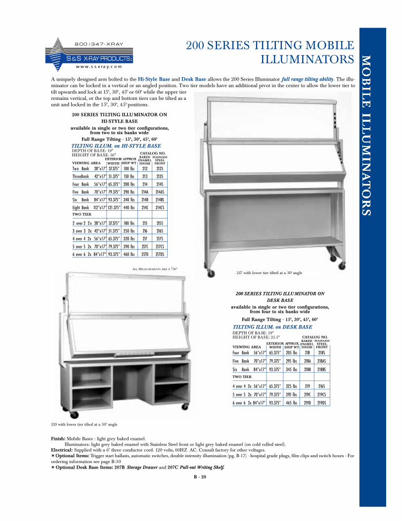
B - 20
200 SERIES TILTING MOBILE ILLUMINATORS
200 SERIES TILTING ILLU MINATOR ONDESK BASE
available in single or two tier configurations,from four to six banks wide
Full Range Tilting - 150, 300, 450, 600
TILTING ILLUM. on DESK BASE
Four Bank 56”x17” 65.375” 205 lbs 218 218S
Five Bank 70”x17” 79.375” 295 lbs 218A 218AS
Six Bank 84”x17” 93.375” 345 lbs 218B 218BS
4 over 4 2x 56”x17” 65.375” 325 lbs 219 216S
5 over 5 2x 70”x17” 79.375” 395 lbs 219C 219CS
6 over 6 2x 84”x17” 93.375” 465 lbs 219D 219DS
VIEWING AREA WIDTH SHIP WT
BAKEDENAMELFINISH
STAINLESSSTEELFRONT
EXTERIOR APPROX.
CATALOG NO.
TWO TIER
DEPTH OF BASE: 19”HEIGHT OF BASE: 25.5”
A uniquely designed arm bolted to the Hi-Style Base and Desk Base allows the 200 Series Illuminator full range tilting ability. The illu-minator can be locked in a vertical or an angled position. Two tier models have an additional pivot in the center to allow the lower tier totilt upwards and lock at 150, 300, 450 or 600 while the upper tierremains vertical, or the top and bottom tiers can be tilted as aunit and locked in the 150, 300, 450 positions.
219 with lower tier tilted at a 300 angle
217 with lower tier tilted at a 300 angle
Finish: Mobile Bases : light grey baked enamel.Illuminators: light grey baked enamel with Stainless Steel front or light grey baked enamel (on cold rolled steel).
Electrical: Supplied with a 6’ three conductor cord. 120 volts, 60HZ AC. Consult factory for other voltages. ✶ Optional Items: Trigger start ballasts, automatic switches, double intensity illumination (pg. B-17) - hospital grade plugs, film clips and switch boxes - Forordering information see page B-30✶ Optional Desk Base Items: 207B Storage Drawer and 207C Pull-out Writing Shelf.
200 SERIES TILTING ILLUMINATOR ONHI-STYLE BASE
available in single or two tier configurations,from two to six banks wide
Full Range Tilting - 150, 300, 450, 600
TILTING ILLUM. on HI-STYLE BASE
Tw o Bank 28”x17” 37.375” 100 lbs 212 212S
ThreeBank 42”x17” 51.375” 150 lbs 213 213S
Four Bank 56”x17” 65.375” 200 lbs 214 214S
Five Bank 70”x17” 79.375” 290 lbs 214A 214AS
Six Bank 84”x17” 93.375” 340 lbs 214B 214BS
Eight Bank 112”x17” 121.375” 440 lbs 214C 214CS
2 over 2 2 x 28”x17” 37.375” 180 lbs 215 215S
3 over 3 2x 42”x17” 51.375” 250 lbs 216 216S
4 over 4 2x 56”x17” 65.375” 320 lbs 217 217S
5 over 5 2x 70”x17” 79.375” 390 lbs 217C 217CS
6 over 6 2x 84”x17” 93.375” 460 lbs 217D 217DS
VIEWING AREA WIDTH SHIP WT
BAKEDENAMELFINISH
STAINLESSSTEELFRONT
EXTERIOR APPROX
CATALOG NO.
TWO TIER
DEPTH OF BASE: 19”HEIGHT OF BASE: 36”
ALL MEASUREMENTS ARE ± 1/16”
8 0 0 / 3 4 7 - X R AY
S &S X- R AY PR O D UCTSw w w. s s x ra y. c o m
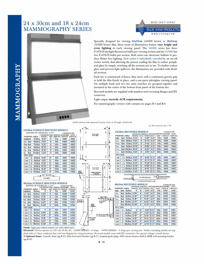
B - 21
24 x 30cm and 18 x 24cm MAMMOGRAPHY SERIES
Specially designed for viewing 24x30cm (146000 Series) or 18x24cm(147000 Series) film, these series of illuminators feature very bright andeven lighting in each viewing panel. The 146000 series has threeF14T8/D daylight fluorescent bulbs per viewing section and the 147000 hastwo F14T8/D bulbs per section. Both series use electronic ballasts to pro-duce flicker free lighting. Each section is individually controlled by an on/offrocker switch, thus allowing the person reading the film to reduce periph-eral glare by simply switching off the sections not in use. To further reduceglare and prevent light spillover, the illuminators are provided with divid-ed sections.
Each tier is constructed of heavy duty steel, with a continuous gravity gripto hold the film firmly in place, and a one piece plexiglass viewing panel.On multiple bank and two tier units switches are grouped together andmounted in the center of the bottom front panel of the bottom tier.
Recessed models are supplied with stainless steel recessing flanges and BXconnector.
Light output exceeds ACR requirements.
For mammography viewers with curtains see pages B-5 and B-6.
Finish: Light gray baked enamel (on cold rolled steel).Electrical: Viewers operate on 120 volt, 60 Hz AC; 146000 SERIES - .8 Amps 147000 SERIES - .6 Amps per viewing area Surface mounting models are sup-plied with a 6’ three conductor line cord (see diagram for wiring locations). Recessed models come with BX connectors. For special voltages consult factory.✶ Optional Items: Console Arms (pg B-25), Film Activated Switches (pg B-17), hospital grade plugs, 68H custom formica shelf & 68HB wall mounting bracket(pg B-30) .
146012 shown with optional Console Arms at 200angle (140272-20)
24x30cm SURFACE MOUNTED MODELSDEPTH OF VIEWE RS: 4.375”
SingleBank 24x30cm 10.437” 16” 21 lbs 146001 146021Tw o Bank 48x30cm 19.875” 16” 42lbs 146002 146022Three Bank 72x30cm 29.312” 16” 63lbs 146003 146023Four Bank 96x30cm 38.750” 16” 84lbs 146004 146024Five Bank 120x30cm 48.187” 16” 105lbs 146005 146025Six Bank 144x30cm 57.625” 16” 126lbs 146006 146026
EXTERIOR DIM APPROXCATALOG NO.
1 over 1 2x 24x30cm 10.437” 32” 42lbs 146011 1460312 over 2 2 x 48x30cm 19.875” 32” 84lbs 146012 1460323 over 3 2x 72x30cm 29.312” 32” 126lbs 146013 1460334 over 4 2x 96x30cm 38.750” 32” 168lbs 146014 1460345 over 5 2x 120x30cm 48.187” 32” 210 lbs 146015 1460356 over 6 2x 144x30cm 57.625” 32” 252 lbs 146016 146036
TWO TIER
STANDARD AUTOVIEWING AREA WIDTH HGT SHIP WT SWITCH SWITCH
Single Bank 24x30cm 10.437” 16” 10.687” 16.25” 21lbsT w o Bank 48x30cm 19.875” 16” 20.125” 16.25” 42lbsTh r e e Bank 72x30cm 29.312” 16” 29.562” 16.25” 63lbsF o u r Bank 96x30cm 38.750” 16” 39.000” 16.25” 84lbsF i v e Bank 120x30cm 48.187” 16” 48.437” 16.25” 105lbsS i x Bank 144x30cm 57.625” 16” 57.875” 16.25” 126lbs
1 over 1 2 x 24x30cm 10.437” 32” 10.687” 32 . 2 5 ” 42lbs2 over 2 2 x 48x30cm 19.875” 32” 20.125” 32 . 2 5 ” 84lbs3 over 3 2 x 72x30cm 29.312” 32” 29.562” 32 . 2 5 ” 126lbs4 over 4 2 x 96x30cm 38.750” 32” 39.000” 32 . 2 5 ” 168lbs5 over 5 2 x120x30cm 48.187” 32” 48.437” 32 . 2 5 ” 210lbs6 over 6 2 x144x30cm 57.625” 32” 57.875” 32 . 2 5 ” 252 lbs
TWO TIER
146041 146061146042 146062146043 146063146044 146064146045 146065146046 146066
146051 146071146052 146072146053 146073146054 146074146055 146075146056 146076
24x30cm RECESSED MODELSEXTERIOR DIM APPROX
CATALOG NO.STANDARD AUTO
VIEWING AREA WIDTH HGT WIDTH H GT SHIP SWITCH SWITCHWALL OPENING
18x24cm SURFACE MOUNTED MODELSDEPTH OF VIEWE RS: 4.375”
SingleBank 18x24cm 8” 16” 17lbs 147001 147021Tw o Bank 36x24cm 15.094” 16” 34lbs 147002 147022Three Bank 54x24cm 22.187” 16” 51lbs 147003 147023Four Bank 72x24cm 29.281” 16” 68lbs 147004 147024Five Bank 90x24cm 36.375” 16” 85lbs 147005 147025Six Bank 108x24cm 43.468” 16” 102lbs 147006 147026
EXTERIOR DIM APPROXCATALOG NO.
1 over 1 2x 18x24cm 8” 32” 34lbs 147011 1470312 over 2 2 x 36x24cm 15.094” 32” 68lbs 147012 1470323 over 3 2x 54x24cm 22.187” 32” 102lbs 147013 1470334 over 4 2x 72x24cm 29.181” 32” 136lbs 147014 1470345 over 5 2x 90x24cm 36.375” 32” 170lbs 147015 1470356 over 6 2x 108x24cm 43.468” 32” 204 lbs 147016 147036
TWO TIER
STANDARD AUTOVIEWING AREA WIDTH HGT SHIP WT SWITCH SWITCH
Single Bank 18x24cm 8” 16” 8.250” 16.25” 17 lbsT w o Bank 36x24cm 15.094” 16” 15.343” 16.25” 34lbsTh r e e Bank 54x24cm 22.187” 16” 22.437” 16.25” 51lbsF o u r Bank 72x24cm 29.281” 16” 29.531” 16.25” 68lbsF i v e Bank 90x24cm 36.375” 16” 36.625” 16.25” 85 lbsS i x Bank 108x24cm 43.468” 16” 43.718” 16.25” 102lbs
1 over 1 2 x 18x24cm 8” 32” 8.250” 32 . 2 5 ” 34lbs2 over 2 2 x 36x24cm 15.094” 32” 15.343” 32 . 2 5 ” 68 lbs3 over 3 2 x 54x24cm 22.187” 32” 22.437” 32 . 2 5 ” 102lbs4 over 4 2 x 72x24cm 29.181” 32” 29.531” 32 . 2 5 ” 136lbs5 over 5 2 x 90x24cm 36.375” 32” 36.625” 32 . 2 5 ” 170 lbs6 over 6 2 x 108x24cm 43.468” 32” 43.718” 32 . 2 5 ” 204 lbs
TWO TIER
147041 147061147042 147062147043 147063147044 147064147045 147065147046 147066
147051 147071147052 147072147053 147073147054 147074147055 147075147056 147076
18x24cm RECESSED MODELSEXTERIOR DIM APPROX
CATALOG NO.STANDARD AUTO
VIEWING AREA WIDTH HGT WIDTH HGT S HIP SWITCH SWITCHWALL OPENING
ALL MEASUREMENTS ARE ± 1/16”
8 0 0 / 3 4 7 - X R AY
S & S X- R AY PR O D UCTSw w w. s s x ra y. c o m
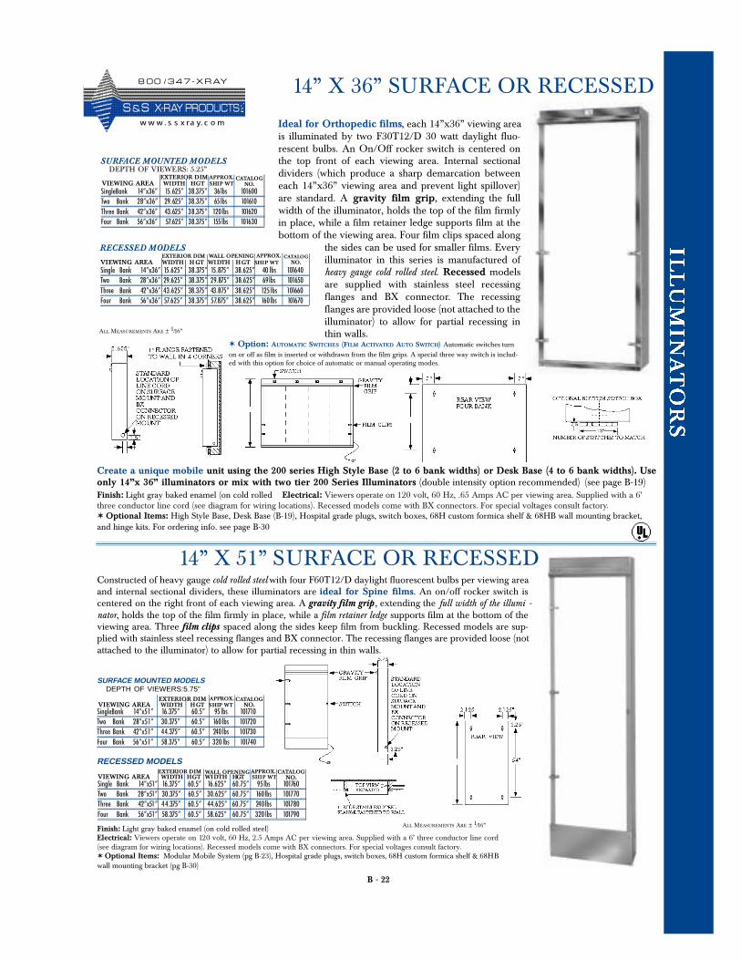
B - 22
14” X 36” SURFACE OR RECESSED
Constructed of heavy gauge cold rolled steel with four F60T12/D daylight fluorescent bulbs per viewing areaand internal sectional dividers, these illuminators are ideal for Spine films. An on/off rocker switch iscentered on the right front of each viewing area. A gravity film grip , extending the full width of the illumi -nator, holds the top of the film firmly in place, while a film retainer ledge supports film at the bottom of theviewing area. Three film clips spaced along the sides keep film from buckling. Recessed models are sup-plied with stainless steel recessing flanges and BX connector. The recessing flanges are provided loose (notattached to the illuminator) to allow for partial recessing in thin walls.
Finish: Light gray baked enamel (on cold rolled steel)Electrical: Viewers operate on 120 volt, 60 Hz, 2.5 Amps AC per viewing area. Supplied with a 6’ three conductor line cord(see diagram for wiring locations). Recessed models come with BX connectors. For special voltages consult factory.✶ Optional Items: Modular Mobile System (pg B-23), Hospital grade plugs, switch boxes, 68H custom formica shelf & 68HBwall mounting bracket (pg B-30)
SURFACE MOUNTED MODELSDEPTH OF VIEWERS:5.75”
SingleBank 14”x51” 16.375” 60.5” 95 lbs 101710Two Bank 28”x51” 30.375” 60.5” 160 lbs 101720Three Bank 42”x51” 44.375” 60.5” 240 lbs 101730Four Bank 56”x51” 58.375” 60.5” 320 lbs 101740
EXTERIOR DIM APPROX. CATALOGNO.VIEWING AREA WIDTH HGT SHIP WT
Single Bank 14”x51” 16.375” 60.5” 16.625” 60.75” 95lbs 101760Two Bank 28”x51” 30.375” 60.5” 30.625” 60.75” 160lbs 101770Three Bank 42”x51” 44.375” 60.5” 44.625” 60.75” 240lbs 101780Four Bank 56”x51” 58.375” 60.5” 58.625” 60.75” 320 lbs 101790
RECESSED MODELSEXTERIOR DIM APPROX.
VIEWING AREA WIDTH HGT WIDTH HGT SHIP WTWALL OPENING CATALOG
NO.
Ideal for Orthopedic films, each 14”x36” viewing areais illuminated by two F30T12/D 30 watt daylight fluo-rescent bulbs. An On/Off rocker switch is centered onthe top front of each viewing area. Internal sectionaldividers (which produce a sharp demarcation betweeneach 14”x36” viewing area and prevent light spillover)are standard. A gravity film grip, extending the fullwidth of the illuminator, holds the top of the film firmlyin place, while a film retainer ledge supports film at thebottom of the viewing area. Four film clips spaced along
the sides can be used for smaller films. Everyilluminator in this series is manufactured ofheavy gauge cold rolled steel. Recessed modelsare supplied with stainless steel recessingflanges and BX connector. The recessingflanges are provided loose (not attached to theilluminator) to allow for partial recessing inthin walls.
14” X 51” SURFACE OR RECESSED
Create a unique mobile unit using the 200 series High Style Base (2 to 6 bank widths) or Desk Base (4 to 6 bank widths). Useonly 14”x 36” illuminators or mix with two tier 200 Series Illuminators (double intensity option recommended) (see page B-19)
ALL MEASUREMENTS ARE ± 1/16”
ALL MEASUREMENTS ARE ± 1/16”
SURFACE MOUNTED MODELSDEPTH OF VIEWERS: 5.25”
SingleBank 14”x36” 15.625” 38.375” 36lbs 101600Two Bank 28”x36” 29.625” 38.375” 65lbs 101610Three Bank 42”x36” 43.625” 38.375” 120lbs 101620Four Bank 56”x36” 57.625” 38.375” 155lbs 101630
EXTERIOR DIM APPROX. CATALOGNO.VIEWING AREA WIDTH HGT SHIP WT
Single Bank 14”x36” 15.625” 38.375” 15.875” 38.625” 40 lbs 101640Two Bank 28”x36” 29.625” 38.375” 29.875” 38.625” 69lbs 101650Three Bank 42”x36” 43.625” 38.375” 43.875” 38.625” 125 lbs 101660Four Bank 56”x36” 57.625” 38.375” 57.875” 38.625” 160lbs 101670
RECESSED MODELSEXTERIOR DIM APPROX.
VIEWING AREA WIDTH H GT WIDTH HGT SHIP WTWALL OPENING CATALOG
NO.
✶ Option: AUTOMATIC SWITCHES (FILM ACTIVATED AUTO SWITCH) Automatic switches turnon or off as film is inserted or withdrawn from the film grips. A special three way switch is includ-ed with this option for choice of automatic or manual operating modes.
Finish: Light gray baked enamel (on cold rolled Electrical: Viewers operate on 120 volt, 60 Hz, .65 Amps AC per viewing area. Supplied with a 6’three conductor line cord (see diagram for wiring locations). Recessed models come with BX connectors. For special voltages consult factory.✶ Optional Items: High Style Base, Desk Base (B-19), Hospital grade plugs, switch boxes, 68H custom formica shelf & 68HB wall mounting bracket,and hinge kits. For ordering info. see page B-30
8 0 0 / 3 4 7 - X R AY
S &S X- R AY PR O D UCTSw w w . s s x ra y. c o m
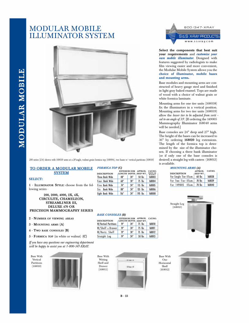
B - 23
MODULAR MOBILE ILLUMINATOR SYSTEM
Select the components that best suityour requirements and customize yourown mobile illuminator. Designed withfeatures suggested by radiologists to makefilm viewing easier and more convenient,the Modular Mobile System allows you thechoice of illuminator, mobile basesand mounting arms.
Base modules and mounting arms are con-structed of heavy gauge steel and finishedin light gray baked enamel. Tops are madeof wood with a choice of walnut grain orwhite formica laminate.
Mounting arms for one tier units (168038)fix the illuminators in a vertical position.Mounting arms for two tier units (168039)allow the lower tier to be adjusted from verti -cal to an angle of 350. [If ordering the 149005Mammography Illuminator 168040 armswill be needed.]
Base consoles are 24” deep and 27” high.The height of the bases can be increased to36” by ordering 168020 leg extensions.The length of the formica top is deter-mined by the size of the illuminator cho-sen. If choosing a three bank illuminator(or if only one of the base consoles isdesired) a straight leg with casters (168013)is available.
FORMICA TOP (C)
LENGTH DEPTHAPPROX. CAT.NO.
200 series (234) shown with 168039 arms at a 200angle, walnut grain formica top (1680 04), two bases w/ vertical partitions (168010 )
TO ORDER A MODULAR MOBILESYSTEM
SELECT:
1 - ILLUMINATOR STYLE: choose from the fol-lowing series -
200, 2000, 4000, 2X, 4X, CIRCULITE, CHAMELEON,
STREAMLINER III,DELUXE 470 OR
PRECISION MAMMOGRAPHY SERIES
2 - NUMBER OF VIEWING AREAS
3 - MOUNTING ARMS (A)
4 - TWO BASE CONSOLES (B)
5 - FORMICA TOP (in white or walnut) (C)
If you have any questions our engineering departmentwill be happy to assist you at 1-800-347-XRAY.
Three Bank Wide 48” 24” 50 lbs 168003Four Bank Wide 60” 24” 75 lbs 168004F ive Bank Wide 74” 24” 115 lbs 168005S ix Bank Wide 88” 24” 155 lbs 168006Eight Bank Wide 116” 24” 195 lbs 168008
EXTERIOR DIMSHIP WT WHITE OR
WALNUTDESCRIPTION
BASE CONSOLES (B)
LENGTH DEPTHAPPROX. CAT.NO.
W/Vertical Partitions 19” 24” 75 lbs 168010W / S h e l f & D r a w e r 19” 24” 75 lbs 168011W/Hori z. S he l f 19” 24” 75 lbs 168012St raigh t L eg 19” 24” 50 lbs 168013
EXTERIOR DIMSHIP WTDESCRIPTION
MOUNTING ARMS (A)APPROX. CAT.NO.
F o r Single T i e r I l l u m . 60 lbs 168038Fo r Two T ie r I l l um. 70 lbs 168039F o r 149 0 05 I l l u m . 70 lbs 168040
SHIP WTDESCRIPTION
Base WithVertical
Partitions(168010)
Base WithWriting
Shelf andDrawer(168011)
Base WithOne
HorizontalShelf
(168012)
Straight Leg (168013)
8 0 0 / 3 4 7 - X R AY
S & S X- R AY PR O D UCTSw w w. s s x ra y. c o m
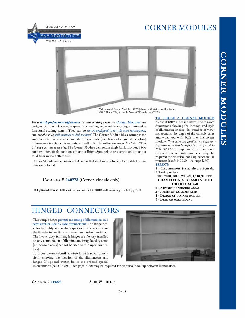
B - 24
CORNER MODULES
For a sharp professional appearance in your reading room our Corner Modules aredesigned to maximize usable space in a reading room while creating an attractivefunctional reading station. They can be custom configured to suit the users requirements,and are able to be wall mounted or desk mounted. The Corner Module fills a corner spaceand mates with a two tier illuminator on each side (see choice of illuminators below)to form an attractive custom designed wall unit. The bottom tier can be fixed at a 200 or350 angle for ease of viewing. The Corner Module can hold a single bank two tier, a twobank two tier, single bank on top and a Bright Spot below or a single on top and asolid filler in the bottom tier.
Corner Modules are constructed of cold rolled steel and are finished to match the illu-minators selected.
✶ Optional Items: 68H custom formica shelf & 68HB wall mounting bracket (pg B-30)
Wall mounted Corner Module (140278) shown with 200 series illuminators(234, 231 and 232), Console Arms at 200 angle (140272-20)
TO ORDER A CORNER MODULEplease SUBMIT A ROUGH SKETCH with roomdimensions showing the location and styleof illuminator chosen, the number of view-ing sections, the angle of the console armsand what you wish built into the cornermodule. If you have any questions our engineer -ing department will be happy to assist you at 1-800-347-XRAY. (If optional switch boxes areordered special interconnects may berequired for electrical hook-up between illu-minators (cat.# 140280 - see page B-30)SELECT:1 - ILLUMINATOR STYLE: choose from thefollowing series -200, 2000, 4000, 2X, 4X, CIRCULITE,CHAMELEON, STREAMLI NER III
OR DELUXE 4702 - NUMBER OF VIEWING AREAS
3 - ANGLE OF CONSOLE ARMS
4 - DESIGN OF CORNER MODULE
5 - DESK OR WALL MOUNT
CATALOG # 140278 (Corner Module only)
HINGED CONNECTORSThis unique hinge permits mounting of illuminators in asemi-circular side by side arrangement. The hinge pro-vides flexibility to gracefully span room corners or to setthe illuminator sections to almost any desired position.The heavy duty full length hinges are factory installedon any combination of illuminators. (Angulated systems[i.e. console arms] cannot be used with hinged connec-tors).To order please submit a sketch, with room dimen-sions, showing the location of the illuminators andhinges. If optional switch boxes are ordered specialinterconnects (cat.# 140280 - see page B-30) may be required for electrical hook-up between illuminators.
CATALOG # 140276 SHIP. WT 16 LBS
8 0 0 / 3 4 7 - X R AY
S &S X- R AY PR O D UCTSw w w. s s x ra y. c o m
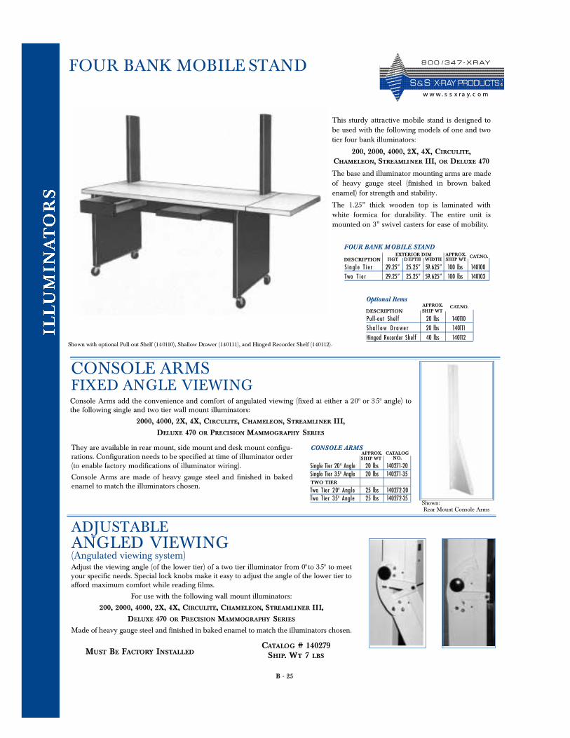
B - 25
FOUR BANK MOBILE STAND
This sturdy attractive mobile stand is designed tobe used with the following models of one and twotier four bank illuminators:
200, 2000, 4000, 2X, 4X, CIRCULITE,CHAMELEON, STREAMLI NER III, OR DELUXE 470
The base and illuminator mounting arms are madeof heavy gauge steel (finished in brown bakedenamel) for strength and stability.
The 1.25” thick wooden top is laminated withwhite formica for durability. The entire unit ismounted on 3” swivel casters for ease of mobility.
Shown with optional Pull-out Shelf (140110), Shallow Drawer (140111), and Hinged Recorder Shelf (140112).
Optional ItemsAPPROX. CAT.NO.
P u l l - o ut Shel f 20 lbs 140110Sha l l o w Drawe r 20 lbs 140111Hinged Recorder Shelf 40 lbs 140112
SHIP WTDESCRIPTION
FOUR BANK MOBILE STAND
HGT DEPTH WIDTHAPPROX. CAT.NO.
Single T i e r 29.25” 25.25” 59.625” 100 lbs 140100Two T i e r 29.25” 25.25” 59.625” 100 lbs 140103
EXTERIOR DIMSHIP WTDESCRIPTION
CONSOLE ARMSFIXED ANGLE VIEWINGConsole Arms add the convenience and comfort of angulated viewing (fixed at either a 200 or 350 angle) tothe following single and two tier wall mount illuminators:
2000, 4000, 2X, 4X, CIRCULITE, CHAMELEON, STREAMLI NER III,
DELUXE 470 OR PRECISION MAMMOGRAPHY SERIES
ADJUSTABLE ANGLED VIEWING(Angulated viewing system)Adjust the viewing angle (of the lower tier) of a two tier illuminator from 00 to 350 to meetyour specific needs. Special lock knobs make it easy to adjust the angle of the lower tier toafford maximum comfort while reading films.
For use with the following wall mount illuminators:
200, 2000, 4000, 2X, 4X, CIRCULITE, CHAMELEON, STREAMLI NER III,
DELUXE 470 OR PRECISION MAMMOGRAPHY SERIES
Made of heavy gauge steel and finished in baked enamel to match the illuminators chosen.
CATALOG # 140279SHIP. WT 7 LBS
MUST BE FACTORY INSTALLED
Single Tier 20 0 Angle 20 lbs 140271-20Single Tier 350 Angle 20 lbs 140271-35
Two Tier 200 A n g l e 25 lbs 140272-20Two Tier 350 A n g l e 25 lbs 140272-35
TWO TIER
SHIP WTAPPROX. CATALOG
NO.
CONSOLE ARMS
Shown:Rear Mount Console Arms
They are available in rear mount, side mount and desk mount configu-rations. Configuration needs to be specified at time of illuminator order(to enable factory modifications of illuminator wiring).
Console Arms are made of heavy gauge steel and finished in bakedenamel to match the illuminators chosen.
8 0 0 / 3 4 7 - X R AY
S & S X- R AY PR O D UCTSw w w. s s x ra y. c o m
B - 26
Three number 2 - 500 watt photoflood bulbs provide extremely bright even illumination forviewing industrial films. Heat is dissipated by a powerful blower, with a removable fiberglass dustfilter, and a heat absorbing glass filter. An on/off toggle switch and a continuous stepless electronic controlprovide variable intensity lighting. The 14”x17” viewing surface is white translucent plexiglass.Four lift up film clips across the top edge of the viewer hold film firmly in place.
EXTERIOR DIMENSIONS: 16.5” Wide / 27.5” High / 20” Deep approx. shipping weight 127 lbs.
Finish: Light gray baked enamel (on cold rolled steel) Electrical: Viewers operate on 120 volt, 60 Hz, 186 - 3.5 Amp AC 189 - 15 Amp AC. Supplied with a 6’ threeconductor line cord.
Ten 15 watt fluorescent bulbs mounted in a special reflector system produce an extremely bright evenillumination for viewing industrial films. The three position toggle switch allows you to choosefull brightness, activate the electronic intensity control or turn the unit off. The stepless electronicvariable intensity control gives full range of illumination. A stainless steel gravity grip extending the fullwidth of the 14”x17” plexiglass viewing panel holds the film firmly in place.
EXTERIOR DIMENSIONS: 15.5” Wide / 24.25” High /10” Deep approx. shipping weight 52 lbs.
Finish: Light Gray baked enamel (on cold rolled steel)Electrical: Viewers operate on 120 volt, 60 Hz, 5 Amp AC. Supplied with a 6’ three conductor line cord. Forspecial voltages consult factory.
EXTERIOR DIMENSIONS: 9” Wide 18” High 14” Deepapprox. shipping weight: 185 - 29 lbs 185I - 30 lbs.
A six inch diameter superbright, superior high intensity, viewing area for reading indus-trial films. These viewers come with an on/off foot switch and a set of steel masks to reduce thesize of the viewing area. A variable intensity electronic control allows you to adjust the brightness ofthe 500 watt photoflood bulb. These illuminators are power air cooled.
The model 185I, in addition to the above, has an adjustable iris which cones down the viewerslight source for reading smaller film areas.
Finish: Light Grey baked enamel (on cold rolled steel) Electrical: Viewers operate on 120 volt, 60 Hz, 9 Amp AC. Supplied with a 6’ three conductor line cord. For special voltages consult factory.
EXTERIOR DIMENSIONS: 24” Wide 10” High 10” Deep approx. shipping weight: 35 lbs.
Designed for industrial radiography. Four number 1photoflood bulbs provide 1000 watts of brightness. An internalheat absorbing glass protects film from heat damage. The coolingsystem utilizes a power driven air supply with replaceable air fil-ters. The electronic brightness control and a built in low lightlevel writing light are mounted at the front of the viewer. This illu-minator comes with an on/ off foot switch and a set of four steelmasks for reading 4.5”x10”, 3.5”x17”, 3.5”x10” or 70mm film.
186 HIGH INTENSITY FLUORESCENT
189 HIGH INTENSITY PHOTOFLOOD
185 AND 185I HIGH INTENSITY
187A 4.5” x 17” HIGH INTENSITY
Finish: Light gray baked enamel (on cold rolled steel) Electrical: Viewers operate on 120 volt, 60 Hz, 186 - 3.5 Amp AC 189 - 15 Amp AC. Supplied with a 6’ threeconductor line cord.
8 0 0 / 3 4 7 - X R AY
S & S X- R AY PR O D UCTSw w w . s s x ra y. c o m
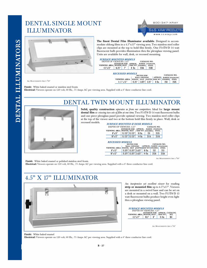
B - 27
DENTAL SINGLE MOUNTILLUMINATOR
Finish: White baked enamel or stainless steel frontsElectrical: Viewers operate on 120 volt, 60 Hz, .75 Amps AC per viewing area. Supplied with a 6’ three conductor line cord.
The finest Dental Film Illuminator available. Designed to accom-modate oblong films in a 4.5”x13” viewing area. Two stainless steel rollerclips are mounted at the top to hold film firmly. One F14T8/D 14 wattfluorescent bulb provides illumination thru the plexiglass viewing panel.Units are available for wall, desk, or recessed mounting.
Finish: White baked enamel or polished stainless steel frontsElectrical: Viewers operate on 120 volt, 60 Hz, .75 Amps AC per viewing area. Supplied with a 6’ three conductor line cord.
Finish: White baked enamelElectrical: Viewers operate on 120 volt, 60 Hz, .75 Amps AC per viewing area. Supplied with a 6’ three conductor line cord.
An inexpensive yet excellent viewer for readingstrip or mounted film up to 4.5”x17”. Viewersare mounted in a swivel base and can be set ona desk or mounted on a wall. Two F15T8/D 15watt fluorescent bulbs produce bright even lightthru a plexiglass viewing panel.
4 . 5 ” x 13 ” 15.25” 5.875” 3.25” 8 lbs 250 250S
RECESS DIMWALL OPENING APPROX.
CATALOG NO.BAKED
ENAMELSTAINLESS
STEELVIEWING AREA WIDTH H GT DEPTH SHIP WT
SURFACE MOUNTED MODELS
4.5”x13” 16.25” 7” 8 lbs 250A 250B
APPROX.VIEWING AREA WIDTH HGT SHIP WT
RECESSED MODELS
CATALOG NO.BAKED
ENAMELSTAINLESS
STEEL
Solid, quality construction separates us from our competitors. Ideal for large mountdental film or viewing two sets of film at one time. Two F14T8/D 14 watt fluorescent bulbsand one piece plexiglass panel provide optimal viewing. Two stainless steel roller clipsat the top of the viewer and two at the bottom hold film firmly in place. Wall, desk orrecessed models.
8 ” x 13 ” 15.375” 13.375” 3.625” 10 lbs 2 52 25310 ” x 12 ” 15.375” 13.375” 3.625” 14 lbs 2 52 A 253A
RECESS DIMWALL OPENING APPROX.
CATALOG NO.BAKED
ENAMELSTAINLESS
STEELVIEWING AREA WIDTH HGT DEPTH SHIP WT
RECESSED MODELS
DENTAL TWIN MOUNT ILLUMINATOR
4.5” X 17” ILLUMINATOR
ALL MEASUREMENTS ARE ± 1/16”
ALL MEASUREMENTS ARE ± 1/16”
ALL MEASUREMENTS ARE ± 1/16”
DEPTH OF VIEWE RS: 5.25”EXTERIOR DIM
SURFACE MOUNTED & DESK MODELS
8”x13” 15.125” 13.125” 10 lbs 251 253S10”x12” 15.125” 13.125” 14 lbs 251A 251B
APPROX.VIEWING AREA WIDTH HGT SHIP WT
CATALOG NO.BAKED
ENAMELSTAINLESS
STEEL
DEPTH OF VIEWE RS: 3.25”EXTERIOR DIM
SURFACE MOUNTED MODELS
4.5”x17” 18.5” 8” 15 lbs 184
APPROX.VIEWING AREA WIDTH HGT SHIP WT
CATALOGNO.
DEPTH OF VIEWE RS: 5.25”EXTERIOR DIM
8 0 0 / 3 4 7 - X R AY
S & S X- R AY PR O D UCTSw w w. s s x ra y. c o m
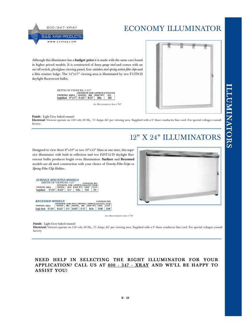
B - 28
ECONOMY ILLUMINATOR
Although this illuminator has a budget price it is made with the same care foundin higher priced models. It is constructed of heavy gauge steel and comes with anon/off switch, plexiglass viewing panel, four stainless steel spring action film clips anda film retainer ledge. The 14”x17” viewing area is illuminated by two F15T8/Ddaylight fluorescent bulbs.
Finish: Light Grey baked enamelElectrical: Viewers operate on 120 volt, 60 Hz, .75 Amps AC per viewing area. Supplied with a 6’ three conductor line cord. For special voltages consultfactory.
DEPTH OF VIEWE RS: 5.375”
SingleBank 14”x17” 15.625” 18.25” 16lbs 200
EXTERIOR DIM APPROX. CATALOGNO.VIEWING AREA WIDTH HGT SHIP WT
Finish: Light Grey baked enamelElectrical: Viewers operate on 120 volt, 60 Hz, .75 Amps AC per viewing area. Supplied with a 6’ three conductor line cord. For special voltages consultfactory.
Designed to view three 8”x10” or two 10”x12” films at one time, this supe-rior illuminator with built in reflectors and two F20T12/D daylight fluo-rescent bulbs produces bright even illumination. Surface and Recessedmodels are all steel construction with your choice of Gravity Film Grips orSpring Film Clip Holders .
SURFACE MOUNTED MODELSDEPTH OF VIEWE RS: 5.25”
SingleBank 12”x24” 24.625” 13.5” 25lbs 254T 254
EXTERIOR DIM APPROXCATALOG NO.GRAVITY
VIEWING AREA WIDTH HGT SHIP WT GRIP CLI P
Single Bank 12”x24” 24.625” 13.5” 24.875” 13.75” 26 lbs 254RT 254R
RECESSED MODELSEXTERIOR DIM APPROX
CATALOG NO.GRAVITY
VIEWING AREA WIDTH HGT WIDTH HGT SHIP WT GRIP CLIPWALL OPENING
FILM
FILM
12” X 24” ILLUMINATORS
ALL MEASUREMENTS ARE ± 1/16”
ALL MEASUREMENTS ARE ± 1/16”
NEED HELP IN SEL ECT ING THE RIGHT IL L UMINATOR FOR YO URA PPL ICAT ION? CALL US AT 800 - 347 - XRAY A ND WE’LL BE HAPPY TOA SSIST YO U !
8 0 0 / 3 4 7 - X R AY
S &S X- R AY PR O D UCTSw w w . s s x ra y. c o m
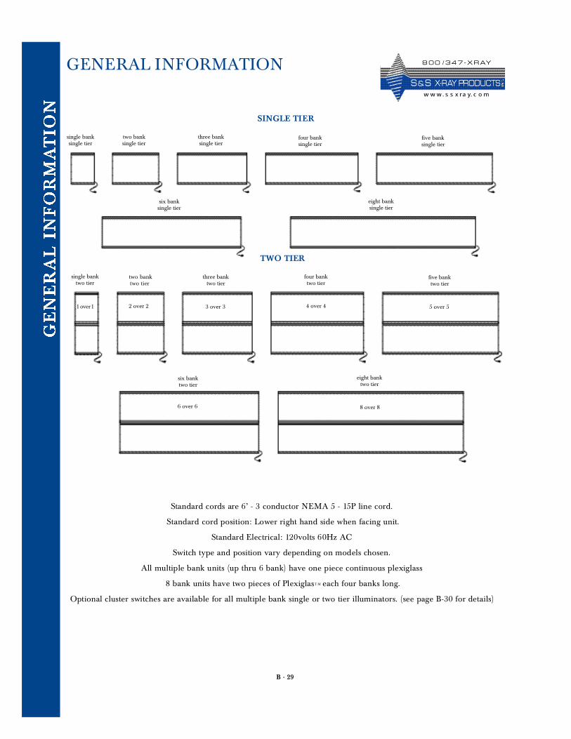
B - 29
TWO TIER
single banksingle tier
two banksingle tier
three banksingle tier
four banksingle tier
five banksingle tier
six banksingle tier
eight banksingle tier
single banktwo tier
two banktwo tier
2 over 2 3 over 3
three banktwo tier
four banktwo tier
4 over 4
five banktwo tier
5 over 5
six banktwo tier
eight banktwo tier
6 over 6 8 over 8
1 over1
SINGLE TIER
Standard cords are 6’ - 3 conductor NEMA 5 - 15P line cord.
Standard cord position: Lower right hand side when facing unit.
Standard Electrical: 120volts 60Hz AC
Sw i t ch type and position vary depending on models ch o s e n .
All multiple bank units (up thru 6 bank) have one piece continuous plexiglass
8 bank units have two pieces of PlexiglasT M e a ch four banks long.
Optional cluster switches are available for all multiple bank single or two tier illuminators. (see page B-30 for details)
GENERAL INFORMATION 8 0 0 / 3 4 7 - X R AY
S & S X- R AY PR O D UCTSw w w. s s x ra y. c o m
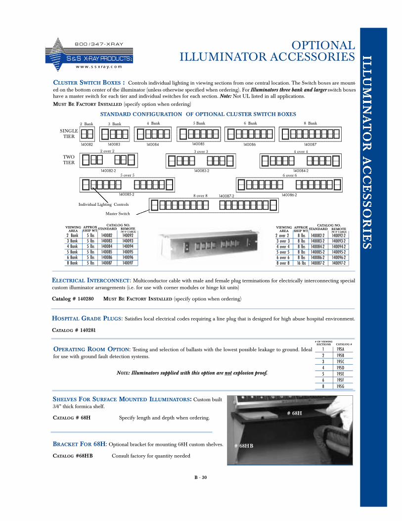
B - 30
OPTIONAL ILLUMINATOR ACCESSORIES
CLUSTER SWITCH BOXES : Controls individual lighting in viewing sections from one central location. The Switch boxes are mount-ed on the bottom center of the illuminator (unless otherwise specified when ordering). For Illuminators three bank and larger switch boxeshave a master switch for each tier and individual switches for each section. Note: Not UL listed in all applications.
MUST BE FACTORY INSTALLED (specify option when ordering)
1 195 A2 195 B3 195 C4 195 D5 195 E6 195 F8 195 G
# OF VIEWINGSECTIONS CATALOG #
NOTE: Illuminators supplied with this option are not explosion proof.
SINGLE TIER
TWOTIER
STANDARD CONFIGURATION OF OPTIONAL CLUSTER SWITCH BOXES
8 over 8
6 over 6
2 Bank 3 Bank
5 over 5
4 over 43 over 32 over 2
4 Bank 5 Bank 6 Bank 8 Bank
140084140083140082
140082-2
140085 140086 140087
140083-2 140084-2
140087-2140085-2 140086-2
Master Switch
Individual Lighting Controls
BRACKET FOR 68H: Optional bracket for mounting 68H custom shelves.
CATALOG #68HB Consult factory for quantity needed
SHELVES FOR SURFACE MOUNTED ILLUMINATORS: Custom built3/4” thick formica shelf.
CATALOG # 68H Specify length and depth when ordering.
OPERATING ROOM OPTION: Testing and selection of ballasts with the lowest possible leakage to ground. Idealfor use with ground fault detection systems.
HOSPITAL GRADE PLUGS: Satisfies local electrical codes requiring a line plug that is designed for high abuse hospital environment.
CATALOG # 140281
ELECTRICAL INTERCONNECT: Multiconductor cable with male and female plug terminations for electrically interconnecting specialcustom illuminator arrangements (i.e. for use with corner modules or hinge kit units)
Catalog # 140280 MUST BE FACTORY INSTALLED (specify option when ordering)
2 Bank 5 lbs 140082 1400923 Bank 5 lbs 140083 1400934 Bank 5 lbs 140084 1400945 Bank 5 lbs 140085 1400956 Bank 5 lbs 140086 1400968 Bank 5 lbs 140087 140097
CATALOG NO.APPROXSHIP WT
VIEWINGAREA
STANDARD REMOTE(W/8’ CABLE)
2 over 2 8 lbs 140082-2 140092-23 over 3 8 lbs 140083-2 140093-24 over 4 8 lbs 140084-2 140094-25 over 5 8 lbs 140085-2 140095-26 over 6 8 lbs 140086-2 140096-28 over 8 16 lbs 140087-2 140097-2
CATALOG NO.APPROXSHIP WT
VIEWINGAREA
STANDARD REMOTE(W/8’ CABLE)
# 68H
# 68HB
8 0 0 / 3 4 7 - X R AY
S &S X- R AY PR O D UCTSw w w . s s x ra y. c o m
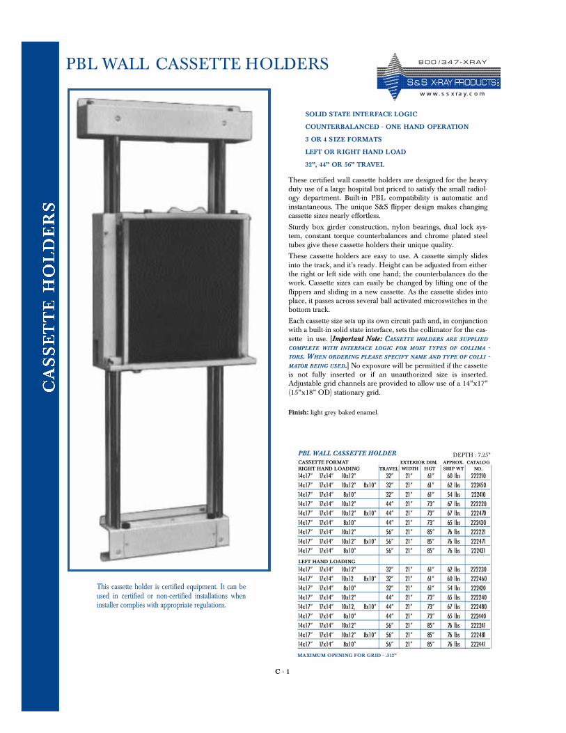
C - 1
PBL WALL CASSETTE HOLDERS
SOLID STATE INTERFACE LOGIC
COUNTERBALANCED - ONE HAND OPERATION
3 OR 4 SIZE FORMATS
LEFT OR R IGHT HAND LOAD
32”, 44” OR 56” TRAVEL
These certified wall cassette holders are designed for the heavyduty use of a large hospital but priced to satisfy the small radiol-ogy department. Built-in PBL compatibility is automatic andinstantaneous. The unique S&S flipper design makes changingcassette sizes nearly effortless.
Sturdy box girder construction, nylon bearings, dual lock sys-tem, constant torque counterbalances and chrome plated steeltubes give these cassette holders their unique quality.
These cassette holders are easy to use. A cassette simply slidesinto the track, and it’s ready. Height can be adjusted from eitherthe right or left side with one hand; the counterbalances do thework. Cassette sizes can easily be changed by lifting one of theflippers and sliding in a new cassette. As the cassette slides intoplace, it passes across several ball activated microswitches in thebottom track.
Each cassette size sets up its own circuit path and, in conjunctionwith a built-in solid state interface, sets the collimator for the cas-sette in use. [Important Note: CASSETTE HOLDERS ARE SUPPLIED
COMPLETE WITH INTERFACE LOGIC FOR MOST TYPES OF COLLIMA -TORS. WHEN ORDERING PLEASE SPECIFY NAME AND TYPE OF COLLI -MATOR BEING USED.] No exposure will be permitted if the cassetteis not fully inserted or if an unauthorized size is inserted.Adjustable grid channels are provided to allow use of a 14”x17”(15”x18” OD) stationary grid.
Finish: light grey baked enamel.
DEPTH : 7.25”
14x17” 17x14” 10x12” 32” 21” 61” 60 lbs 22221014x17” 17x14” 10x12” 8x10” 32” 21” 61” 62 lbs 22245014x17” 17x14” 8x10” 32” 21” 61” 54 lbs 22241014x17” 17x14” 10x12” 44” 21” 73” 67 lbs 22222014x17” 17x14” 10x12” 8x10” 44” 21” 73” 67 lbs 22247014x17” 17x14” 8x10” 44” 21” 73” 65 lbs 22243014x17” 17x14” 10x12” 56” 21” 85” 76 lbs 22222114x17” 17x14” 10x12” 8x10” 56” 21” 85” 76 lbs 22247114x17” 17x14” 8x10” 56” 21” 85” 76 lbs 222431
14x17” 17x14” 10x12” 32” 21” 61” 62 lbs 22223014x17” 17x14” 10x12 8x10” 32” 21” 61” 60 lbs 22246014x17” 17x14” 8x10” 32” 21” 61” 54 lbs 22242014x17” 17x14” 10x12” 44” 21” 73” 65 lbs 22224014x17” 17x14” 10x12, 8x10” 44” 21” 73” 67 lbs 22248014x17” 17x14” 8x10” 44” 21” 73” 65 lbs 22244014x17” 17x14” 10x12” 56” 21” 85” 76 lbs 22224114x17” 17x14” 10x12” 8x10” 56” 21” 85” 76 lbs 22248114x17” 17x14” 8x10” 56” 21” 85” 76 lbs 222441
WIDTH HGT SHIP WTEXTERIOR DIM. APPROX. CATALOG
NO.RIGHT HAND LOADINGCASSETTE FORMAT
TRAVEL
LEFT HAND LOADING
PBL WALL CASSETTE HOLDER
This cassette holder is certified equipment. It can beused in certified or non-certified installations wheninstaller complies with appropriate regulations.
MAXIMUM OPENING FOR GRID - .312”
8 0 0 / 3 4 7 - X R AY
S & S X- R AY PR O D UCTSw w w. s s x ra y. c o m
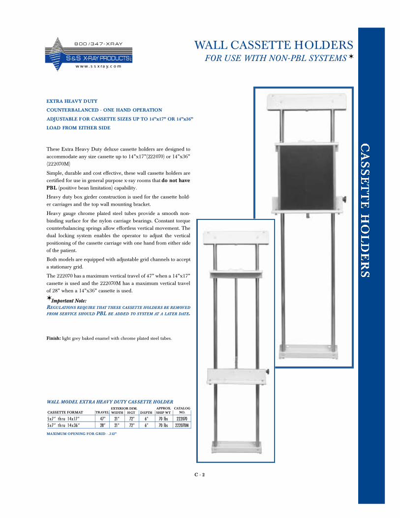
C - 2
WALL CASSETTE HOLDERSFOR USE WITH NON-PBL SYSTEMS ✶
EXTRA HEAVY DUTY
COUNTERBALANCED - ONE HAND OPERATION
ADJUSTABLE FOR CASSETTE SIZES UP TO 14”x17” OR 14”x36”
LOAD FROM EITHER SIDE
These Extra Heavy Duty deluxe cassette holders are designed toaccommodate any size cassette up to 14”x17”(222070) or 14”x36”(222070M)
Simple, durable and cost effective, these wall cassette holders arecertified for use in general purpose x-ray rooms that do not havePBL (positive bean limitation) capability.
Heavy duty box girder construction is used for the cassette hold-er carriages and the top wall mounting bracket.
Heavy gauge chrome plated steel tubes provide a smooth non-binding surface for the nylon carriage bearings. Constant torquecounterbalancing springs allow effortless vertical movement. Thedual locking system enables the operator to adjust the verticalpositioning of the cassette carriage with one hand from either sideof the patient.
Both models are equipped with adjustable grid channels to accepta stationary grid.
The 222070 has a maximum vertical travel of 47” when a 14”x17”cassette is used and the 222070M has a maximum vertical travelof 28” when a 14”x36” cassette is used.
✶ Important Note: REGULATIONS REQUIRE THAT THESE CASSETTE HOLDERS BE REMOVED
FROM SERVICE SHOULD PBL BE ADDED TO SYSTEM AT A LATER DATE.
5x7” th ru 14 x 17 ” 47” 21” 72” 6” 70 lbs 2220705x7” th ru 14 x 36 ” 28” 21” 72” 6” 70 lbs 222070M
WIDTH HGT DEPTH SHIP WTEXTERIOR DIM. APPROX. CATALOG
NO.CASSETTE FORMAT TRAVEL
WALL MODEL EXTRA HEAVY DUTY CASSETTE HOLDER
Finish: light grey baked enamel with chrome plated steel tubes.
MAXIMUM OPENING FOR GRID - .312”
8 0 0 / 3 4 7 - X R AY
S &S X- R AY PR O D UCTSw w w . s s x ra y. c o m
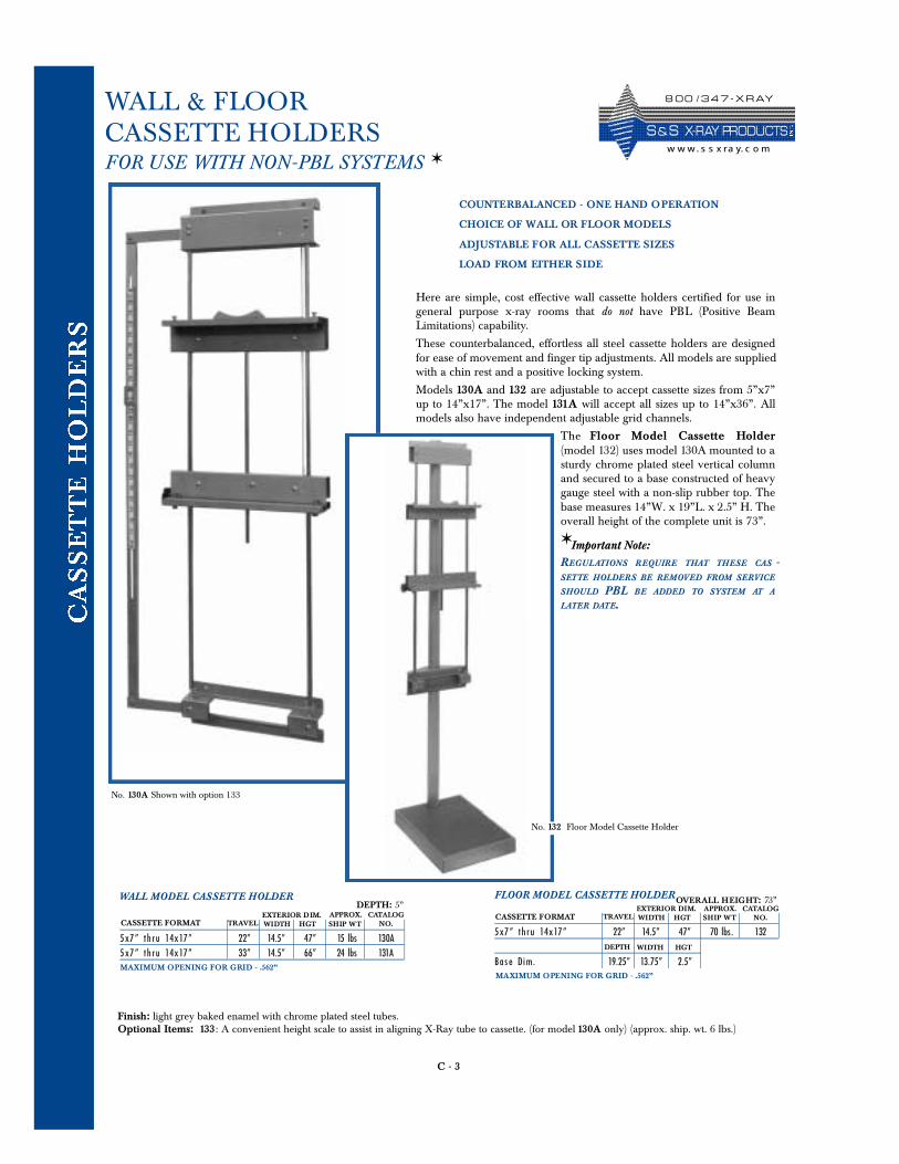
C - 3
WALL & FLOORCASSETTE HOLDERSFOR USE WITH NON-PBL SYSTEMS ✶
COUNTERBALANCED - ONE HAND OPERATION
CHOICE OF WALL OR FLOOR MODELS
ADJUSTABLE FOR ALL CASSETTE SIZES
LOAD FROM EITHER SIDE
Here are simple, cost effective wall cassette holders certified for use ingeneral purpose x-ray rooms that do not have PBL (Positive BeamLimitations) capability.
These counterbalanced, effortless all steel cassette holders are designedfor ease of movement and finger tip adjustments. All models are suppliedwith a chin rest and a positive locking system.
Models 130A and 132 are adjustable to accept cassette sizes from 5”x7”up to 14”x17”. The model 131A will accept all sizes up to 14”x36”. Allmodels also have independent adjustable grid channels.
The Floor Model Cassette Ho l d e r(model 132) uses model 130A mounted to asturdy chrome plated steel vertical columnand secured to a base constructed of heavygauge steel with a non-slip rubber top. Thebase measures 14”W. x 19”L. x 2.5” H. Theoverall height of the complete unit is 73”.
✶ Important Note: RE GULATIONS RE QUIRE TH AT THESE C A S -SETTE HOLDERS BE REMOVED FROM SERVICE
SHOULD PBL BE ADDED TO SYSTEM AT A
LATER DATE.
DEPTH: 5”
5x7” th ru 14 x 17 ” 22” 14.5” 47” 15 lbs 130A5x7” th ru 14 x 17 ” 33” 14.5” 66” 24 lbs 131A
WIDTH HGT SHIP WTEXTERIOR DIM. APPROX. CATALOG
NO.CASSETTE FORMAT TRAVEL
WALL MODEL CASSETTE HOLDER
Finish: light grey baked enamel with chrome plated steel tubes.Optional Items: 133: A convenient height scale to assist in aligning X-Ray tube to cassette. (for model 130A only) (approx. ship. wt. 6 lbs.)
5x7” th ru 14 x 17 ” 22” 14.5” 47” 70 lbs. 132
B a s e Dim. 19.25” 13.75” 2.5”
WIDTH HGT SHIP WTEXTERIOR DIM. APPROX. CATALOG
NO.CASSETTE FORMAT TRAVEL
FLOOR MODEL CASSETTE HOLDER
DEPTH WIDTH HGT
OVERALL HEIGHT: 73”
No. 130A Shown with option 133
No. 132 Floor Model Cassette Holder
MAXIMUM OPENING FOR GRID - .562”MAXIMUM OPENING FOR GRID - .562”
8 0 0 / 3 4 7 - X R AY
S & S X- R AY PR O D UCTSw w w. s s x ra y. c o m
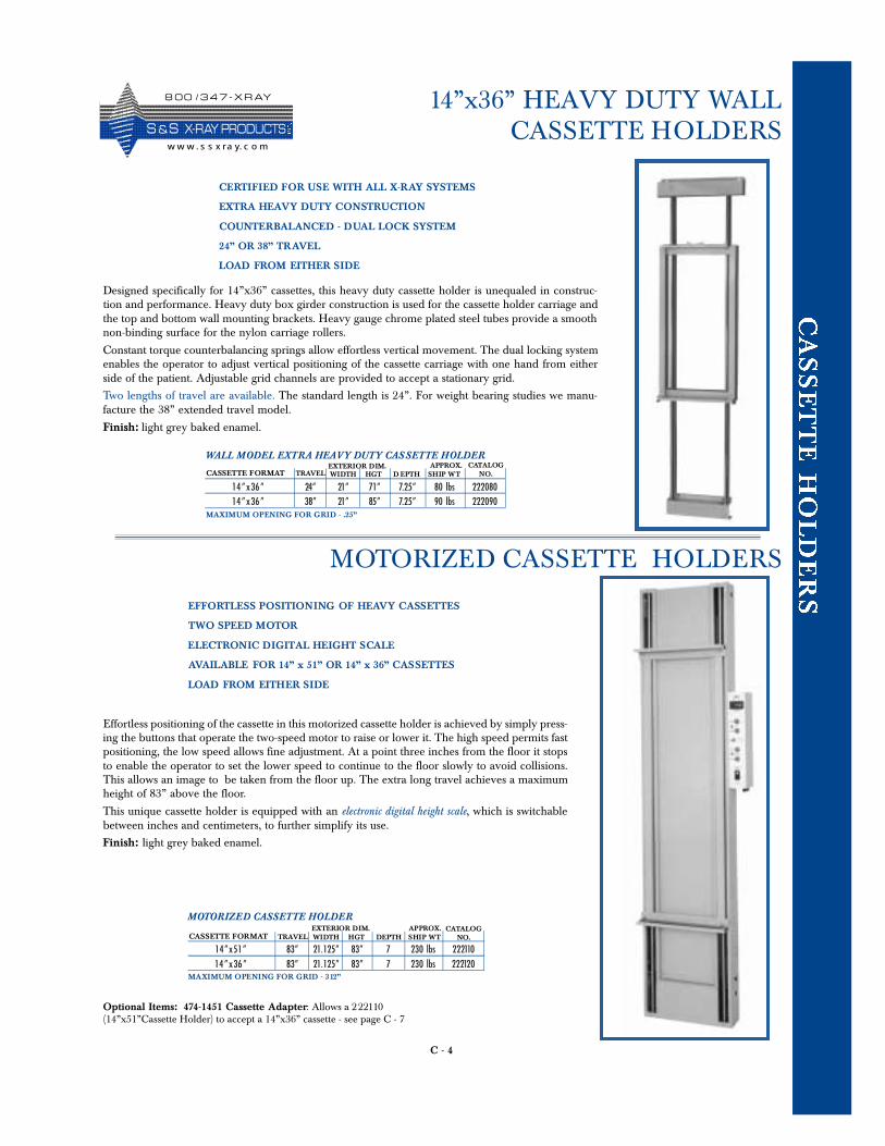
C - 4
14”x36” HEAVY DUTY WALL CASSETTE HOLDERS
CERTIFIED FOR USE WITH ALL X-RAY SYSTEMS
EXTRA HEAVY DUTY CONSTRUCTION
COUNTERBALANCED - DUAL LOCK SYSTEM
24” OR 38” TRAVEL
LOAD FROM EITHER SIDE
Designed specifically for 14”x36” cassettes, this heavy duty cassette holder is unequaled in construc-tion and performance. Heavy duty box girder construction is used for the cassette holder carriage andthe top and bottom wall mounting brackets. Heavy gauge chrome plated steel tubes provide a smoothnon-binding surface for the nylon carriage rollers.
Constant torque counterbalancing springs allow effortless vertical movement. The dual locking systemenables the operator to adjust vertical positioning of the cassette carriage with one hand from eitherside of the patient. Adjustable grid channels are provided to accept a stationary grid.
Two lengths of travel are available. The standard length is 24”. For weight bearing studies we manu-facture the 38” extended travel model.
Finish: light grey baked enamel.
14 ” x 36 ” 24” 21” 71” 7.25” 80 lbs 22208014 ” x 36 ” 38” 21” 85” 7.25” 90 lbs 222090
WIDTH HGT D EPTH SHIP WTEXTERIOR DIM. APPROX. CATALOG
NO.CASSETTE FORMAT TRAVEL
EFFORTLESS POSITIONING OF HEAVY CASSETTES
TWO SPEED MOTOR
ELECTRONIC DIGITAL HEIGHT SCALE
AVAILABLE FOR 14” x 51” OR 14” x 36” CASSETTES
LOAD FROM EITHER SIDE
Effortless positioning of the cassette in this motorized cassette holder is achieved by simply press-ing the buttons that operate the two-speed motor to raise or lower it. The high speed permits fastpositioning, the low speed allows fine adjustment. At a point three inches from the floor it stopsto enable the operator to set the lower speed to continue to the floor slowly to avoid collisions.This allows an image to be taken from the floor up. The extra long travel achieves a maximumheight of 83” above the floor.
This unique cassette holder is equipped with an electronic digital height scale, which is switchablebetween inches and centimeters, to further simplify its use.
Finish: light grey baked enamel.
14 ” x 51 ” 83” 21.125” 83” 7 230 lbs 22211014 ” x 36 ” 83” 21.125” 83” 7 230 lbs 222120
WIDTH HGT DEPTH SHIP WTEXTERIOR DIM. APPROX. CATALOG
NO.CASSETTE FORMAT TRAVEL
MOTORIZED CASSETTE HOLDERS
Optional Items: 474-1451 Cassette Adapter: Allows a 222110(14”x51”Cassette Holder) to accept a 14”x36” cassette - see page C - 7
WALL MODEL EXTRA HEAVY DUTY CASSETTE HOLDER
MOTORIZED CASSETTE HOLDER
MAXIMUM OPENING FOR GRID - .25”
MAXIMUM OPENING FOR GRID - 312”
8 0 0 / 3 4 7 - X R AY
S &S X- R AY PR O D UCTSw w w . s s x ra y. c o m
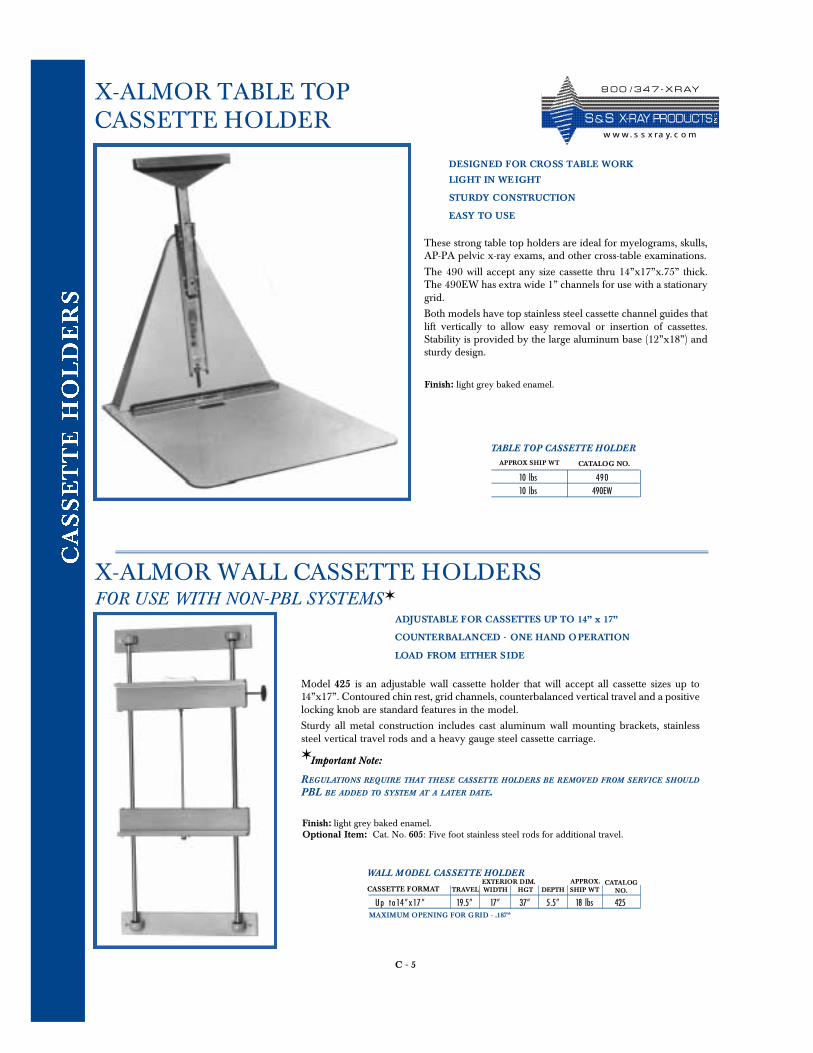
C - 5
X-ALMOR WALL CASSETTE HOLDERSFOR USE WITH NON-PBL SYSTEMS ✶
ADJUSTABLE FOR CASSETTES UP TO 14” x 17”
COUNTERBALANCED - ONE HAND OPERATION
LOAD FROM EITHER SIDE
Model 425 is an adjustable wall cassette holder that will accept all cassette sizes up to14”x17”. Contoured chin rest, grid channels, counterbalanced vertical travel and a positivelocking knob are standard features in the model.
Sturdy all metal construction includes cast aluminum wall mounting brackets, stainlesssteel vertical travel rods and a heavy gauge steel cassette carriage.
✶ Important Note:
REGULATIONS REQUIRE THAT THESE CASSETTE HOLDERS BE REMOVED FROM SERVICE SHOULD
PBL BE ADDED TO SYSTEM AT A LATER DATE.
Up to 14 ” x 17 ” 19.5” 17” 37” 5.5” 18 lbs 425WIDTH HGT DEPTH SHIP WTEXTERIOR DIM. APPROX. CATALOG
NO.CASSETTE FORMAT TRAVEL
Finish: light grey baked enamel.Optional Item: Cat. No. 605: Five foot stainless steel rods for additional travel.
WALL MODEL CASSETTE HOLDER
MAXIMUM OPENING FOR GRID - .187”
X-ALMOR TABLE TOPCASSETTE HOLDER
DESIGNED FOR CROSS TABLE WORK
LIGHT IN WEIGHT
STURDY CONSTRUCTION
EASY TO USE
These strong table top holders are ideal for myelograms, skulls,AP-PA pelvic x-ray exams, and other cross-table examinations.
The 490 will accept any size cassette thru 14”x17”x.75” thick. The 490EW has extra wide 1” channels for use with a stationarygrid.
Both models have top stainless steel cassette channel guides thatlift vertically to allow easy removal or insertion of cassettes.Stability is provided by the large aluminum base (12”x18”) andsturdy design.
Finish: light grey baked enamel.
10 lbs 49 010 lbs 490EW
APPROX SHIP WT CATALOG NO.
TABLE TOP CASSETTE HOLDER
8 0 0 / 3 4 7 - X R AY
S & S X- R AY PR O D UCTSw w w. s s x ra y. c o m
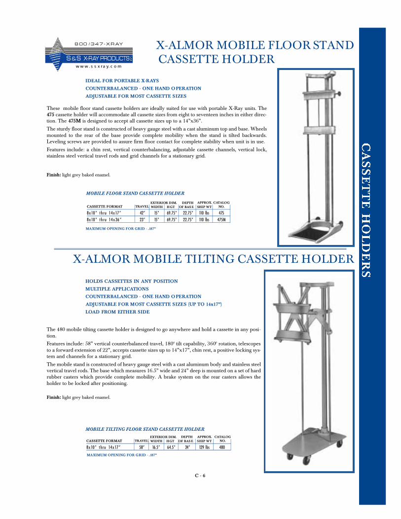
C - 6
X-ALMOR MOBILE FLOOR STANDCASSETTE HOLDER
IDEAL FOR PORTABLE X-RAYS
COUNTERBALANCED - ONE HAND OPERATION
ADJUSTABLE FOR MOST CASSETTE SIZES
These mobile floor stand cassette holders are ideally suited for use with portable X-Ray units. The475 cassette holder will accommodate all cassette sizes from eight to seventeen inches in either direc-tion. The 475M is designed to accept all cassette sizes up to a 14”x36”.
The sturdy floor stand is constructed of heavy gauge steel with a cast aluminum top and base. Wheelsmounted to the rear of the base provide complete mobility when the stand is tilted backwards.Leveling screws are provided to assure firm floor contact for complete stability when unit is in use.
Features include: a chin rest, vertical counterbalancing, adjustable cassette channels, vertical lock,stainless steel vertical travel rods and grid channels for a stationary grid.
Finish: light grey baked enamel.
8 x 10” th ru 14 x 17 ” 42” 15” 69.75” 22.75” 110 lbs 4758 x 10” th ru 14 x 36 ” 23” 15” 69.75” 22.75” 110 lbs 475M
WIDTH H GT OF BAS E SHIP WTEXTERIOR DIM. APPROX. CATALOG
NO.CASSETTE FORMAT TRAVEL
MOBILE FLOOR STAND CASSETTE HOLDER
MAXIMUM OPENING FOR GRID - .187”
HOLDS CASSETTES IN ANY POSITION
MULTIPLE APPLICATIONS
COUNTERBALANCED - ONE HAND OPERATION
ADJUSTABLE FOR MOST CASSETTE SIZES (UP TO 14x17”)
LOAD FROM EITHER SIDE
The 480 mobile tilting cassette holder is designed to go anywhere and hold a cassette in any posi-tion.
Features include: 58” vertical counterbalanced travel, 1800 tilt capability, 3600 rotation, telescopesto a forward extension of 22”, accepts cassette sizes up to 14”x17”, chin rest, a positive locking sys-tem and channels for a stationary grid.
The mobile stand is constructed of heavy gauge steel with a cast aluminum body and stainless steelvertical travel rods. The base which measures 16.5” wide and 24” deep is mounted on a set of hardrubber casters which provide complete mobility. A brake system on the rear casters allows theholder to be locked after positioning.
Finish: light grey baked enamel.
8 x 10” t hru 14 x 17 ” 58” 16.5” 64.5” 24” 129 lbs 480WIDTH HGT OF BAS E SHIP WTEXTERIOR DIM. APPROX. CATALOG
NO.CASSETTE FORMAT TRAVEL
MOBILE TILTING FLOOR STAND CASSETTE HOLDER
MAXIMUM OPENING FOR GRID - .187”
X-ALMOR MOBILE TILTING CASSETTE HOLDER
DEPTH
DEPTH
8 0 0 / 3 4 7 - X R AY
S &S X- R AY PR O D UCTSw w w . s s x ra y. c o m
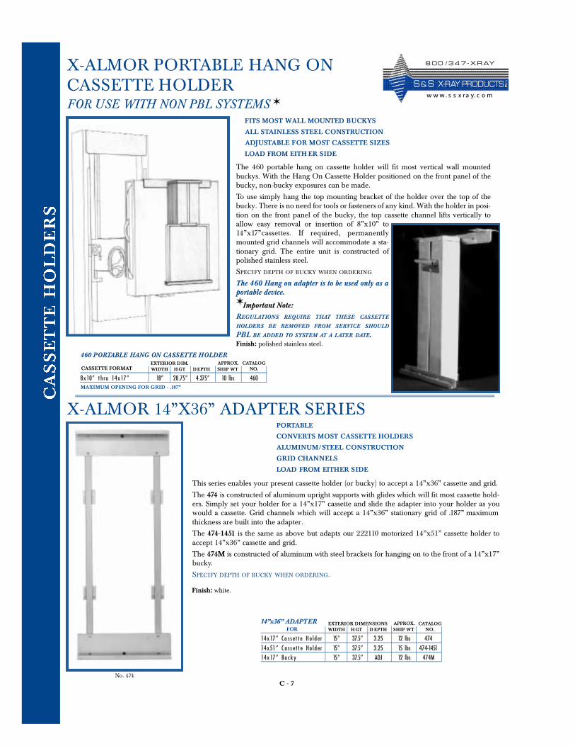
C - 7
X-ALMOR PORTABLE HANG ONCASSETTE HOLDERFOR USE WITH NON PBL SYSTEMS ✶
FITS MOST WALL MOUNTED BUCKYS
ALL STAINLESS STEEL CONSTRUCTION
ADJUSTABLE FOR MOST CASSETTE SIZES
LOAD FROM EITH ER SIDE
The 460 portable hang on cassette holder will fit most vertical wall mountedbuckys. With the Hang On Cassette Holder positioned on the front panel of thebucky, non-bucky exposures can be made.
To use simply hang the top mounting bracket of the holder over the top of thebucky. There is no need for tools or fasteners of any kind. With the holder in posi-tion on the front panel of the bucky, the top cassette channel lifts vertically toallow easy removal or insertion of 8”x10” to14 ” x 17”cassettes. If required, permanentlymounted grid channels will accommodate a sta-tionary grid. The entire unit is constructed ofpolished stainless steel.
SPECIFY DEPTH OF BUCKY WHEN ORDERING
The 460 Hang on adapter is to be used only as aportable device.✶ Important Note:
RE GULATIONS RE QUIRE TH AT THESE C A SSETTE
HOLDERS BE REMOVED FROM SERVICE SHOULD
PBL BE ADDED TO SYSTEM AT A LATER DATE.Finish: polished stainless steel.
8 x 10” t hru 14 x 17 ” 18” 20.75” 4.375” 10 lbs 460WIDTH H GT DEPTH SHIP WTEXTERIOR DIM. APPROX. CATALOG
NO.CASSETTE FORMAT
460 PORTABLE HANG ON CASSETTE HOLDER
X-ALMOR 14”X36” ADAPTER SERIESPORTABLE
CONVERTS MOST CASSETTE HOLDERS
ALUMINUM/STEEL CONSTRUCTION
GRID CHANNELS
LOAD FROM EITHER SIDE
This series enables your present cassette holder (or bucky) to accept a 14”x36” cassette and grid.
The 474 is constructed of aluminum upright supports with glides which will fit most cassette hold-ers. Simply set your holder for a 14”x17” cassette and slide the adapter into your holder as youwould a cassette. Grid channels which will accept a 14”x36” stationary grid of .187” maximumthickness are built into the adapter.
The 474-1451 is the same as above but adapts our 222110 motorized 14”x51” cassette holder toaccept 14”x36” cassette and grid.
The 474M is constructed of aluminum with steel brackets for hanging on to the front of a 14”x17”bucky.
SPECIFY DEPTH OF BUCKY WHEN ORDERING.
Finish: white.
14 x 17” Ca sse t t e Ho lder 15” 37.5” 3.25 12 lbs 47414 x 51” Cass e t t e Ho lder 15” 37.5” 3.25 15 lbs 474-145114 x 17” Buck y 15” 37.5” ADJ 12 lbs 474M
WIDTH H GT D EPTH SHIP WTEXTERIOR DIMENSIONS APPROX. CATALOG
NO.FOR14”x36” ADAPTER
MAXIMUM OPENING FOR GRID - .187”
No. 474
8 0 0 / 3 4 7 - X R AY
S & S X- R AY PR O D UCTSw w w. s s x ra y. c o m
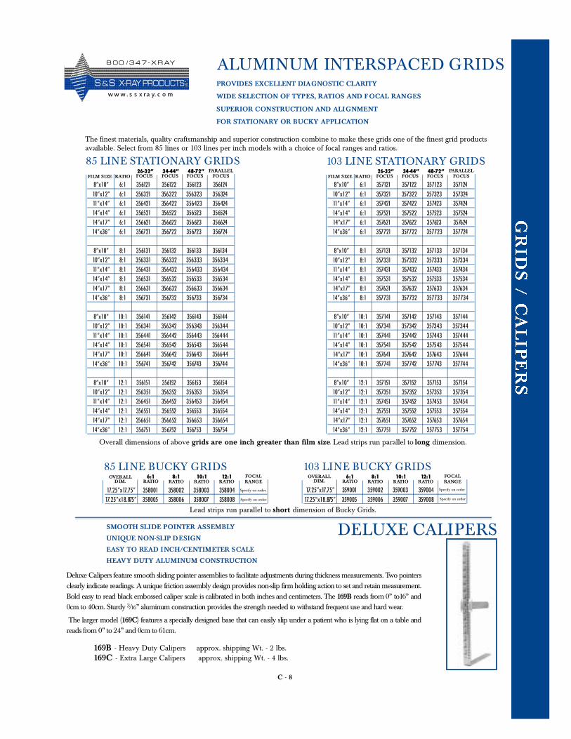
C - 8
ALUMINUM INTERSPACED GRIDS
DELUXE CALIPERS
Deluxe Calipers feature smooth sliding pointer assemblies to facilitate adjustments during thickness measurements. Two pointersclearly indicate readings. A unique friction assembly design provides non-slip firm holding action to set and retain measurement.Bold easy to read black embossed caliper scale is calibrated in both inches and centimeters. The 16 9 B reads from 0” to16” and0cm to 40cm. Sturdy 3/16” aluminum construction provides the strength needed to withstand frequent use and hard wear.
The larger model (16 9 C) features a specially designed base that can easily slip under a patient who is lying flat on a table andreads from 0” to 24” and 0cm to 61 c m .
SMOOTH SLIDE POINTER ASSEMBLY
UNIQUE NON-SLIP DESIGN
EASY TO READ INCH/CENTIMETER SCALE
HEAVY DUTY ALUMINUM CONSTRUCTION
169B - Heavy Duty Calipers approx. shipping Wt. - 2 lbs. 169C - Extra Large Calipers approx. shipping Wt. - 4 lbs.
8”x10” 6:1 356121 356122 356123 35612410”x12” 6:1 356321 356322 356323 35632411”x14” 6:1 356421 356422 356423 35642414”x14” 6:1 356521 356522 356523 35652414”x17” 6:1 356621 356622 356623 35662414”x36” 6:1 356721 356722 356723 356724
8”x10” 8:1 356131 356132 356133 35613410”x12” 8:1 356331 356332 356333 35633411”x14” 8:1 356431 356432 356433 35643414”x14” 8:1 356531 356532 356533 35653414”x17” 8:1 356631 356632 356633 35663414”x36” 8:1 356731 356732 356733 356734
8”x10” 10:1 356141 356142 356143 35614410”x12” 10:1 356341 356342 356343 35634411”x14” 10:1 356441 356442 356443 35644414”x14” 10:1 356541 356542 356543 35654414”x17” 10:1 356641 356642 356643 35664414”x36” 10:1 356741 356742 356743 356744
8”x10” 12:1 356151 356152 356153 35615410”x12” 12:1 356351 356352 356353 35635411”x14” 12:1 356451 356452 356453 35645414”x14” 12:1 356551 356552 356553 35655414”x17” 12:1 356651 356652 356653 35665414”x36” 12:1 356751 356752 356753 356754
PROVIDES EXCELLENT DIAGNOSTIC CLARITY
WIDE SELECTION OF TYPES, RATIOS AND FOCAL RANGES
SUPERIOR CONSTRUCTION AND ALIGNMENT
FOR STATIONARY OR BUCKY APPLICATION
The finest materials, quality craftsmanship and superior construction combine to make these grids one of the finest grid productsavailable. Select from 85 lines or 103 lines per inch models with a choice of focal ranges and ratios.
85 LINE STATIONARY GRIDSFILM SIZE RATIO
26-32”FOCUS
34-44”FOCUS
48-72”FOCUS
PARALLELFOCUS
8”x10” 6:1 357121 357122 357123 35712410”x12” 6:1 357321 357322 357323 35732411”x14” 6:1 357421 357422 357423 35742414”x14” 6:1 357521 357522 357523 35752414”x17” 6:1 357621 357622 357623 35762414”x36” 6:1 357721 357722 357723 357724
8”x10” 8:1 357131 357132 357133 35713410”x12” 8:1 357331 357332 357333 35733411”x14” 8:1 357431 357432 357433 35743414”x14” 8:1 357531 357532 357533 35753414”x17” 8:1 357631 357632 357633 35763414”x36” 8:1 357731 357732 357733 357734
8”x10” 10:1 357141 357142 357143 35714410”x12” 10:1 357341 357342 357343 35734411”x14” 10:1 357441 357442 357443 35744414”x14” 10:1 357541 357542 357543 35754414”x17” 10:1 357641 357642 357643 35764414”x36” 10:1 357741 357742 357743 357744
8”x10” 12:1 357151 357152 357153 35715410”x12” 12:1 357351 357352 357353 35735411”x14” 12:1 357451 357452 357453 35745414”x14” 12:1 357551 357552 357553 35755414”x17” 12:1 357651 357652 357653 35765414”x36” 12:1 357751 357752 357753 357754
103 LINE STATIONARY GRIDSFILM SIZE RATIO
26-32”FOCUS
34-44”FOCUS
48-72”FOCUS
PARALLELFOCUS
Overall dimensions of above grids are one inch greater than film size. Lead strips run parallel to long dimension.
17.25”x17.75” 358001 358002 358003 35800417.25”x18.875” 358005 358006 358007 358008
85 LINE BUCKY GRIDSOVERALL
DIM.8:1
RATIO10:1
RATIO12:1
RATIOFOCALRANGE
6:1RATIO
Specify on order 17.25”x17.75” 359001 359002 359003 35900417.25”x18.875” 359005 359006 359007 359008
103 LINE BUCKY GRIDSOVERALL
DIM.8:1
RATIO10:1
RATIO12:1
RATIOFOCALRANGE
6:1RATIO
Lead strips run parallel to short dimension of Bucky Grids.
Specify on order
Specify on order
Specify on order
8 0 0 / 3 4 7 - X R AY
S &S X- R AY PR O D UCTSw w w . s s x ra y. c o m
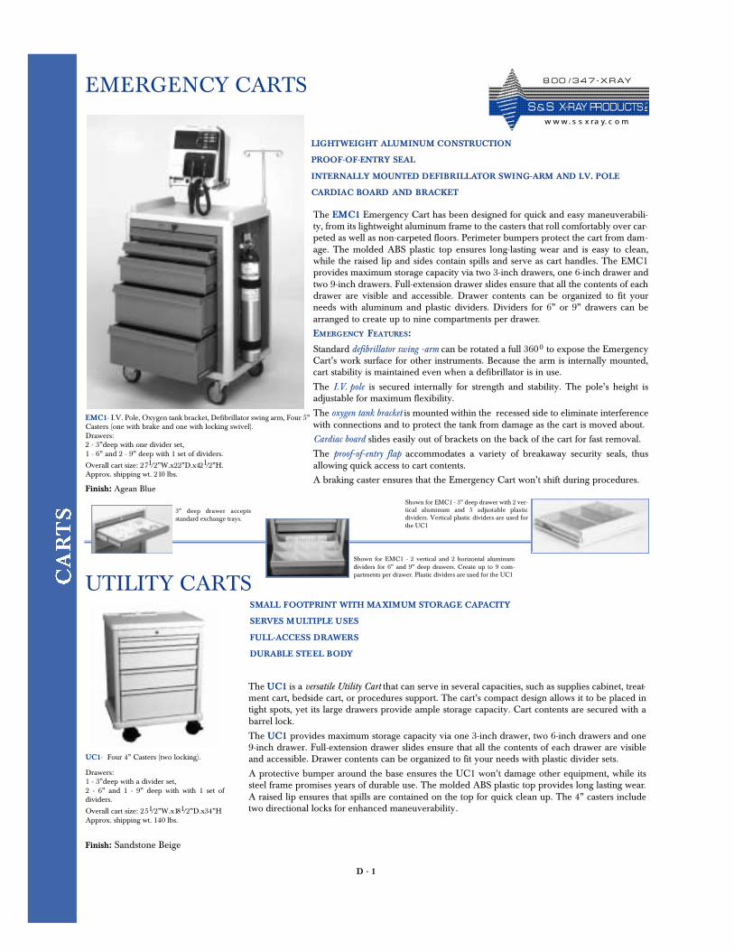
D - 1
EMERGENCY CARTS
The EMC1 Emergency Cart has been designed for quick and easy maneuverabili-ty, from its lightweight aluminum frame to the casters that roll comfortably over car-peted as well as non-carpeted floors. Perimeter bumpers protect the cart from dam-age. The molded ABS plastic top ensures long-lasting wear and is easy to clean,while the raised lip and sides contain spills and serve as cart handles. The EMC1provides maximum storage capacity via two 3-inch drawers, one 6-inch drawer andtwo 9-inch drawers. Full-extension drawer slides ensure that all the contents of eachdrawer are visible and accessible. Drawer contents can be organized to fit yourneeds with aluminum and plastic dividers. Dividers for 6” or 9” drawers can bearranged to create up to nine compartments per drawer.
EMERGENCY FEATURES:
Standard defibrillator swing -arm can be rotated a full 3600 to expose the EmergencyCart’s work surface for other instruments. Because the arm is internally mounted,cart stability is maintained even when a defibrillator is in use.
The I.V. pole is secured internally for strength and stability. The pole’s height isadjustable for maximum flexibility.
The oxygen tank bracket is mounted within the recessed side to eliminate interferencewith connections and to protect the tank from damage as the cart is moved about.
Cardiac board slides easily out of brackets on the back of the cart for fast removal.
The proof-of-entry flap accommodates a variety of breakaway security seals, thusallowing quick access to cart contents.
A braking caster ensures that the Emergency Cart won’t shift during procedures.
LIGHTWEIGHT ALUMINUM CONSTRUCTION
PROOF-OF-ENTRY SEAL
INTERNALLY MOUNTED DEFIBRILLATOR SWING-ARM AND I.V. POLE
CARDIAC BOARD AND BRACKET
UTILITY CARTS
EMC1- I.V. Pole, Oxygen tank bracket, Defibrillator swing arm, Four 5”Casters (one with brake and one with locking swivel). Drawers: 2 - 3”deep with one divider set, 1 - 6” and 2 - 9” deep with 1 set of dividers.
Overall cart size: 271/2”W.x22”D.x421/2”H. Approx. shipping wt. 210 lbs.
Finish: Agean Blue
The UC1 is a versatile Utility Cart that can serve in several capacities, such as supplies cabinet, treat-ment cart, bedside cart, or procedures support. The cart’s compact design allows it to be placed intight spots, yet its large drawers provide ample storage capacity. Cart contents are secured with abarrel lock.
The UC1 provides maximum storage capacity via one 3-inch drawer, two 6-inch drawers and one9-inch drawer. Full-extension drawer slides ensure that all the contents of each drawer are visibleand accessible. Drawer contents can be organized to fit your needs with plastic divider sets.
A protective bumper around the base ensures the UC1 won’t damage other equipment, while itssteel frame promises years of durable use. The molded ABS plastic top provides long lasting wear.A raised lip ensures that spills are contained on the top for quick clean up. The 4” casters includetwo directional locks for enhanced maneuverability.
Finish: Sandstone Beige
UC1- Four 4” Casters (two locking).
SMALL FOOTPRINT WITH MAXIMUM STORAGE CAPACITY
SERVES MULTIPLE USES
FULL-ACCESS DRAWERS
DURABLE STEEL BODY
Shown for EMC1 - 3” deep drawer with 2 ver-tical aluminum and 5 adjustable plasticdividers. Vertical plastic dividers are used forthe UC1
3” deep drawer acceptsstandard exchange trays.
Shown for EMC1 - 2 vertical and 2 horizontal aluminumdividers for 6” and 9” deep drawers. Create up to 9 com-partments per drawer. Plastic dividers are used for the UC1
Drawers: 1 - 3”deep with a divider set, 2 - 6” and 1 - 9” deep with with 1 set ofdividers.
Overall cart size: 251/2”W.x181/2”D.x34”HApprox. shipping wt. 140 lbs.
8 0 0 / 3 4 7 - X R AY
S & S X- R AY PR O D UCTSw w w. s s x ra y. c o m
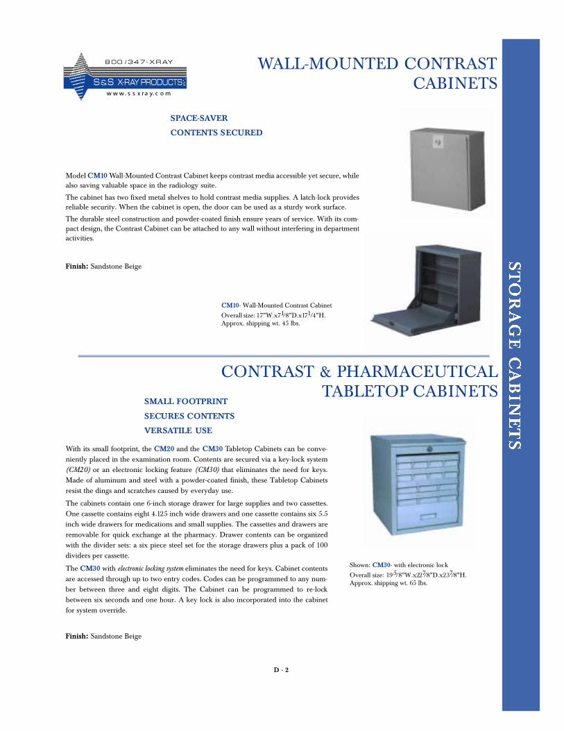
D - 2
WALL-MOUNTED CONTRASTCABINETS
SMALL FOOTPRINT
SECURES CONTENTS
VERSATILE USE
Finish: Sandstone Beige
CONTRAST & PHARMACEUTICAL TABLETOP CABINETS
SPACE-SAVER
CONTENTS SECURED
Model CM10 Wall-Mounted Contrast Cabinet keeps contrast media accessible yet secure, whilealso saving valuable space in the radiology suite.
The cabinet has two fixed metal shelves to hold contrast media supplies. A latch-lock providesreliable security. When the cabinet is open, the door can be used as a sturdy work surface.
The durable steel construction and powder-coated finish ensure years of service. With its com-pact design, the Contrast Cabinet can be attached to any wall without interfering in departmentactivities.
With its small footprint, the CM20 and the CM30 Tabletop Cabinets can be conve-niently placed in the examination room. Contents are secured via a key-lock system(CM20) or an electronic locking feature (CM30) that eliminates the need for keys.Made of aluminum and steel with a powder-coated finish, these Tabletop Cabinetsresist the dings and scratches caused by everyday use.
The cabinets contain one 6-inch storage drawer for large supplies and two cassettes.One cassette contains eight 4.125 inch wide drawers and one cassette contains six 5.5inch wide drawers for medications and small supplies. The cassettes and drawers areremovable for quick exchange at the pharmacy. Drawer contents can be organizedwith the divider sets: a six piece steel set for the storage drawers plus a pack of 100dividers per cassette.
The CM30 with electronic locking system eliminates the need for keys. Cabinet contentsare accessed through up to two entry codes. Codes can be programmed to any num-ber between three and eight digits. The Cabinet can be programmed to re-lockbetween six seconds and one hour. A key lock is also incorporated into the cabinetfor system override.
CM10- Wall-Mounted Contrast Cabinet
Overall size: 17”W.x71/8”D.x171/4”H. Approx. shipping wt. 45 lbs.
Shown: CM30- with electronic lock
Overall size: 195/8”W.x227/8”D.x237/8”H. Approx. shipping wt. 65 lbs.
Finish: Sandstone Beige
8 0 0 / 3 4 7 - X R AY
S &S X- R AY PR O D UCTSw w w. s s x ra y. c o m
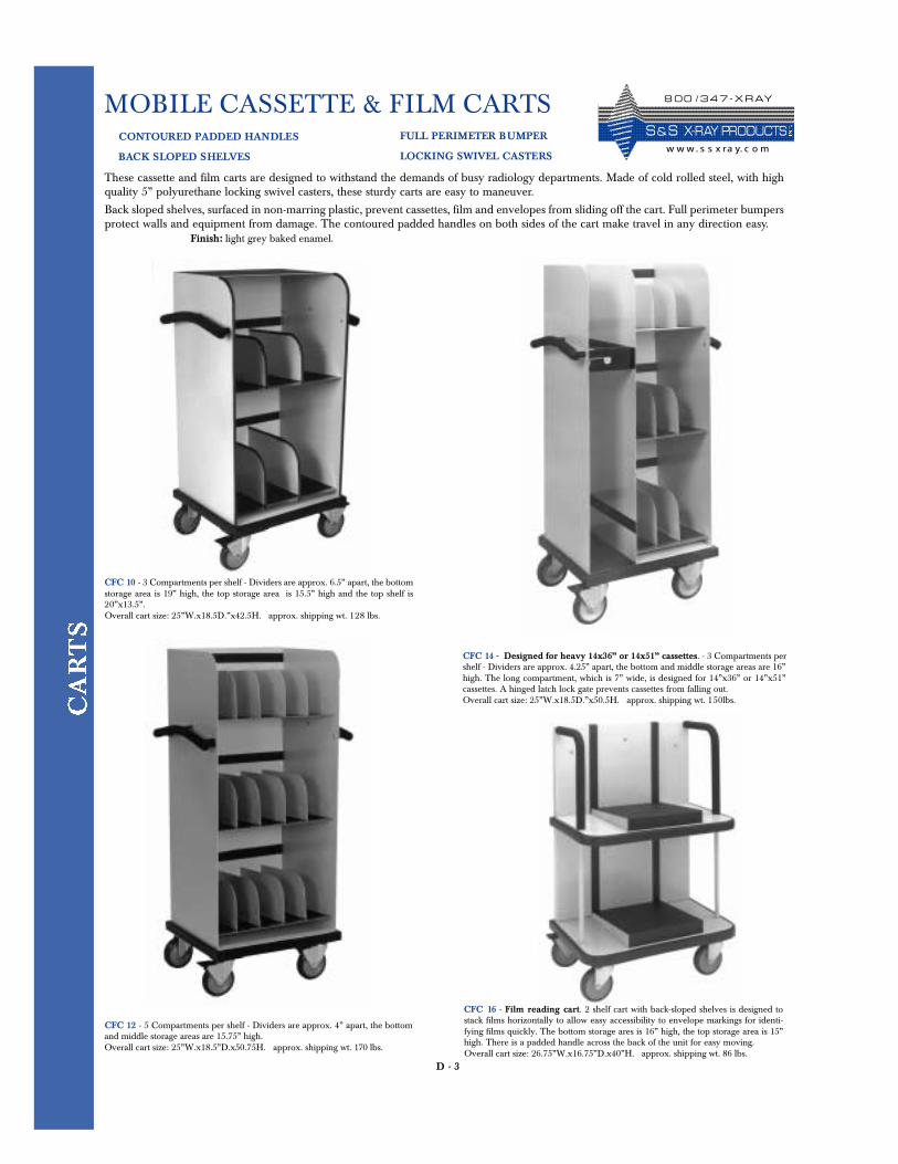
D - 3
MOBILE CASSETTE & FILM CARTSCONTOURED PADDED HANDLES
BACK SLOPED SHELVES
These cassette and film carts are designed to withstand the demands of busy radiology departments. Made of cold rolled steel, with highquality 5” polyurethane locking swivel casters, these sturdy carts are easy to maneuver.
Back sloped shelves, surfaced in non-marring plastic, prevent cassettes, film and envelopes from sliding off the cart. Full perimeter bumpersprotect walls and equipment from damage. The contoured padded handles on both sides of the cart make travel in any direction easy.
CFC 10 - 3 Compartments per shelf - Dividers are approx. 6.5” apart, the bottomstorage area is 19” high, the top storage area is 15.5” high and the top shelf is20”x13.5”.Overall cart size: 25”W.x18.5D.”x42.5H. approx. shipping wt. 128 lbs.
Finish: light grey baked enamel.
CFC 12 - 5 Compartments per shelf - Dividers are approx. 4” apart, the bottomand middle storage areas are 15.75” high. Overall cart size: 25”W.x18.5”D.x50.75H. approx. shipping wt. 170 lbs.
CFC 14 - Designed for heavy 14x36” or 14x51” cassettes. - 3 Compartments pershelf - Dividers are approx. 4.25” apart, the bottom and middle storage areas are 16”high. The long compartment, which is 7” wide, is designed for 14”x36” or 14”x51”cassettes. A hinged latch lock gate prevents cassettes from falling out.Overall cart size: 25”W.x18.5D.”x50.5H. approx. shipping wt. 150lbs.
CFC 16 - Film reading cart. 2 shelf cart with back-sloped shelves is designed tostack films horizontally to allow easy accessibility to envelope markings for identi-fying films quickly. The bottom storage ares is 16” high, the top storage area is 15”high. There is a padded handle across the back of the unit for easy moving.Overall cart size: 26.75”W.x16.75”D.x40”H. approx. shipping wt. 86 lbs.
FULL PERIMETER BUMPER
LOCKING SWIVEL CASTERS
8 0 0 / 3 4 7 - X R AY
S & S X- R AY PR O D UCTSw w w. s s x ra y. c o m
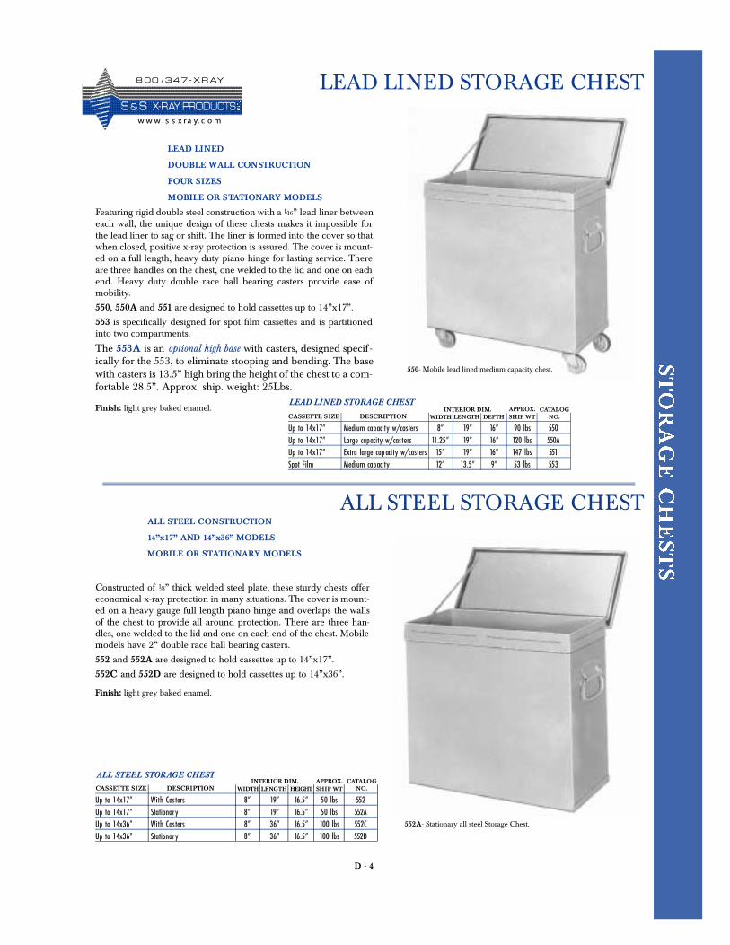
D - 4
LEAD LINED STORAGE CHEST
LEAD LINED
DOUBLE WALL CONSTRUCTION
FOUR SIZES
MOBILE OR STATIONARY MODELS
Featuring rigid double steel construction with a 1/16” lead liner betweeneach wall, the unique design of these chests makes it impossible forthe lead liner to sag or shift. The liner is formed into the cover so thatwhen closed, positive x-ray protection is assured. The cover is mount-ed on a full length, heavy duty piano hinge for lasting service. Thereare three handles on the chest, one welded to the lid and one on eachend. Heavy duty double race ball bearing casters provide ease ofmobility.
550, 550A and 551 are designed to hold cassettes up to 14”x17”.
553 is specifically designed for spot film cassettes and is partitionedinto two compartments.
The 553A is an optional high base with casters, designed specif -ically for the 553, to eliminate stooping and bending. The basewith casters is 13.5” high bring the height of the chest to a com-fortable 28.5”. Approx. ship. weight: 25Lbs.
Finish: light grey baked enamel.
Up to 14x17” Medium capacity w/casters 8” 19” 16” 90 lbs 550Up to 14x17” Large capacity w/casters 11.25” 19” 16” 120 lbs 550AUp to 14x17” Extra large cap acity w/casters 15” 19” 16” 147 lbs 551Spot Film Medium capacity 12” 13.5” 9” 53 lbs 553
LENGTH DEPTH SHIP WTINTERIOR DIM. APPROX. CATALOG
NO.CASSETTE SIZE DESCRIPTION WIDTH
LEAD LINED STORAGE CHEST
ALL STEEL CONSTRUCTION
14”x17” AND 14”x36” MODELS
MOBILE OR STATIONARY MODELS
Constructed of 1/8” thick welded steel plate, these sturdy chests offereconomical x-ray protection in many situations. The cover is mount-ed on a heavy gauge full length piano hinge and overlaps the wallsof the chest to provide all around protection. There are three han-dles, one welded to the lid and one on each end of the chest. Mobilemodels have 2” double race ball bearing casters.
552 and 552A are designed to hold cassettes up to 14”x17”.
552C and 552D are designed to hold cassettes up to 14”x36”.
552A- Stationary all steel Storage Chest.
Finish: light grey baked enamel.
Up to 14x17” With Casters 8” 19” 16.5” 50 lbs 552Up to 14x17” Stationary 8” 19” 16.5” 50 lbs 552AUp to 14x36” With Casters 8” 36” 16.5” 100 lbs 552CUp to 14x36” Stationary 8” 36” 16.5” 100 lbs 552D
LENGTH HEIGHT SHIP WTINTERIOR DIM. APPROX. CATALOG
NO.CASSETTE SIZE DESCRIPTION WIDTH
ALL STEEL STORAGE CHEST
ALL STEEL STORAGE CHEST
550- Mobile lead lined medium capacity chest.
8 0 0 / 3 4 7 - X R AY
S &S X- R AY PR O D UCTSw w w . s s x ra y. c o m
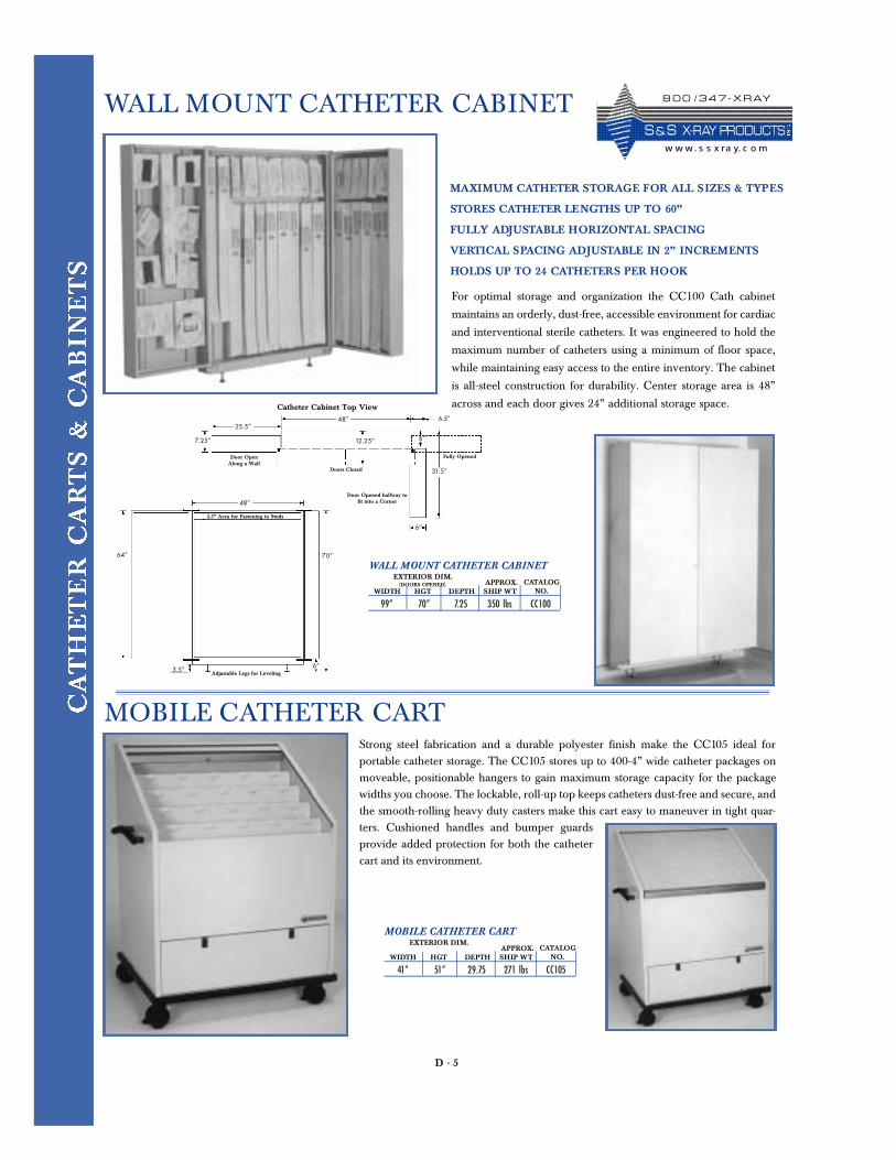
D - 5
WALL MOUNT CATHETER CABINET
MAXIMUM CATHETER STORAGE FOR ALL SIZES & TYPES
STORES CATHETER LENGTHS UP TO 60”
FULLY ADJUSTABLE HORIZONTAL SPACING
VERTICAL SPACING ADJUSTABLE IN 2” INCREMENTS
HOLDS UP TO 24 CATHETERS PER HOOK
For optimal storage and organization the CC100 Cath cabinet
maintains an orderly, dust-free, accessible environment for cardiac
and interventional sterile catheters. It was engineered to hold the
maximum number of catheters using a minimum of floor space,
while maintaining easy access to the entire inventory. The cabinet
is all-steel construction for durability. Center storage area is 48”
across and each door gives 24” additional storage space.
99” 70” 7.25 350 lbs CC100WIDTH HGT SHIP WT
EXTERIOR DIM. (DOORS OPENED) APPROX. CATALOG
NO.DEPTH
WALL MOUNT CATHETER CABINET
25.5”48”
6”
6”
31.5”
12.25”
6.5”
7.25”
Doors Closed
Door OpenAlong a Wall
Door Opened halfway tofit into a Corner
Catheter Cabinet Top View
MOBILE CATHETER CARTStrong steel fabrication and a durable polyester finish make the CC105 ideal forportable catheter storage. The CC105 stores up to 400-4” wide catheter packages onmoveable, positionable hangers to gain maximum storage capacity for the packagewidths you choose. The lockable, roll-up top keeps catheters dust-free and secure, andthe smooth-rolling heavy duty casters make this cart easy to maneuver in tight quar-ters. Cushioned handles and bumper guardsprovide added protection for both the cathetercart and its environment.
41” 51” 29.75 271 lbs CC105WIDTH HGT SHIP WT
EXTERIOR DIM. APPROX. CATALOG
NO.DEPTH
MOBILE CATHETER CART
Fully Opened
70”64”
48”
6”3.5”
2.5” Area for Fastening to Studs
Adjustable Legs for Leveling
8 0 0 / 3 4 7 - X R AY
S & S X- R AY PR O D UCTSw w w. s s x ra y. c o m
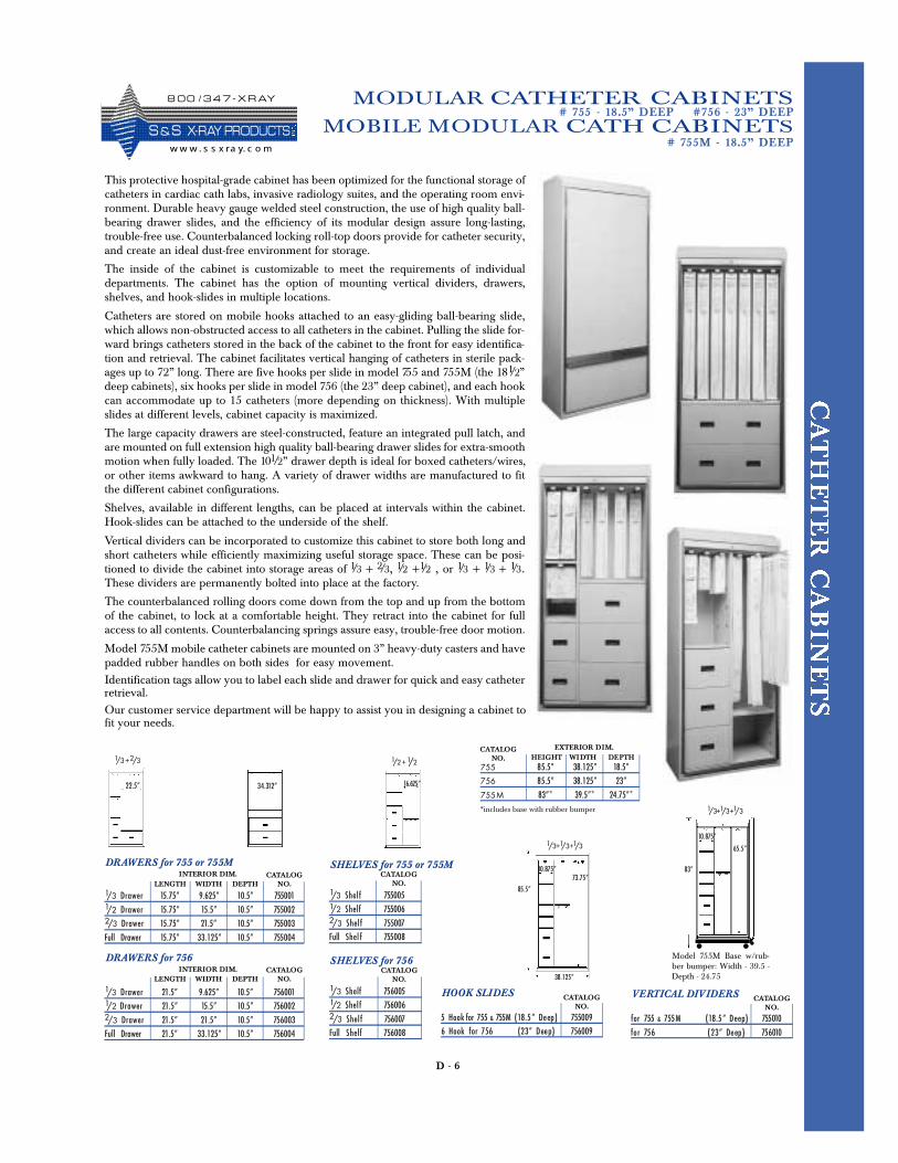
D - 6
MODULAR CATHETER CABINETS
MOBILE MODULAR CATH CABINETS# 755M - 18.5” DEEP
LENGTH WIDTHINTERIOR DIM. CATALOG
NO.DEPTH
DRAWERS for 755 or 755M
1/3 D r a w e r 15.75” 9.625” 10.5” 7550011/2 D r a w e r 15.75” 15.5” 10.5” 7550022/3 D r a w e r 15.75” 21.5” 10.5” 755003
Full Drawer 15.75” 33.125” 10.5” 755004
LENGTH WIDTHINTERIOR DIM. CATALOG
NO.DEPTH
DRAWERS for 756
1/3 D r a w e r 21.5” 9.625” 10.5” 7560011/2 D r a w e r 21.5” 15.5” 10.5” 7560022/3 D r a w e r 21.5” 21.5” 10.5” 756003
Full Drawer 21.5” 33.125” 10.5” 756004
CATALOGNO.
SHELVES for 755 or 755M
1/3 S h e lf 7550051/2 S h e lf 7550062/3 S h e lf 755007
Full S h e l f 755008
CATALOGNO.
HOOK SLIDES
5 Hook for 755 & 755M ( 18.5” Deep) 755009
6 Hook for 756 (23” Deep) 756009
CATALOGNO.
SHELVES for 756
1/3 S h e lf 7560051/2 S h e lf 7560062/3 S h e lf 756007
Full S h e lf 756008
CATALOGNO.
VERTICAL DIVIDERS
for 755 & 755M (18.5” Deep) 755010
for 756 (23” Deep) 756010
This protective hospital-grade cabinet has been optimized for the functional storage ofcatheters in cardiac cath labs, invasive radiology suites, and the operating room envi-ronment. Durable heavy gauge welded steel construction, the use of high quality ball-bearing drawer slides, and the efficiency of its modular design assure long-lasting,trouble-free use. Counterbalanced locking roll-top doors provide for catheter security,and create an ideal dust-free environment for storage.
The inside of the cabinet is customizable to meet the requirements of individualdepartments. The cabinet has the option of mounting vertical dividers, drawers,shelves, and hook-slides in multiple locations.
Catheters are stored on mobile hooks attached to an easy-gliding ball-bearing slide,which allows non-obstructed access to all catheters in the cabinet. Pulling the slide for-ward brings catheters stored in the back of the cabinet to the front for easy identifica-tion and retrieval. The cabinet facilitates vertical hanging of catheters in sterile pack-ages up to 72” long. There are five hooks per slide in model 755 and 755M (the 181/2”deep cabinets), six hooks per slide in model 756 (the 23” deep cabinet), and each hookcan accommodate up to 15 catheters (more depending on thickness). With multipleslides at different levels, cabinet capacity is maximized.
The large capacity drawers are steel-constructed, feature an integrated pull latch, andare mounted on full extension high quality ball-bearing drawer slides for extra-smoothmotion when fully loaded. The 101/2” drawer depth is ideal for boxed catheters/wires,or other items awkward to hang. A variety of drawer widths are manufactured to fitthe different cabinet configurations.
Shelves, available in different lengths, can be placed at intervals within the cabinet.Hook-slides can be attached to the underside of the shelf.
Vertical dividers can be incorporated to customize this cabinet to store both long andshort catheters while efficiently maximizing useful storage space. These can be posi-tioned to divide the cabinet into storage areas of 1/3 + 2/3, 1/2 +1/2 , or 1/3 + 1/3 + 1/3.These dividers are permanently bolted into place at the factory.
The counterbalanced rolling doors come down from the top and up from the bottomof the cabinet, to lock at a comfortable height. They retract into the cabinet for fullaccess to all contents. Counterbalancing springs assure easy, trouble-free door motion.
Model 755M mobile catheter cabinets are mounted on 3” heavy-duty casters and havepadded rubber handles on both sides for easy movement.Identification tags allow you to label each slide and drawer for quick and easy catheterretrieval.Our customer service department will be happy to assist you in designing a cabinet tofit your needs.
34.312” 16.625”22.5”
1/3+1/3+1/3
10.875”
38.125”
73.75”
85.5”
1/3 +2/3 1/2+1/2
# 755 - 18.5” DEEP #756 - 23” DEEP
1/3+1/3+1/3
10.875”
65.5”
83”
Model 755M Base w/rub-ber bumper: Width - 39.5 -Depth - 24.75
HEIGHT WIDTHEXTERIOR DIM. CATALOG
NO. DEPTH755 85.5” 38.125” 18.5”
756 85.5” 38.125” 23”
755 M 83”* 39.5”* 24.75”*
*includes base with rubber bumper
8 0 0 / 3 4 7 - X R AY
S & S X- R AY PR O D UCTSw w w . s s x ra y. c o m
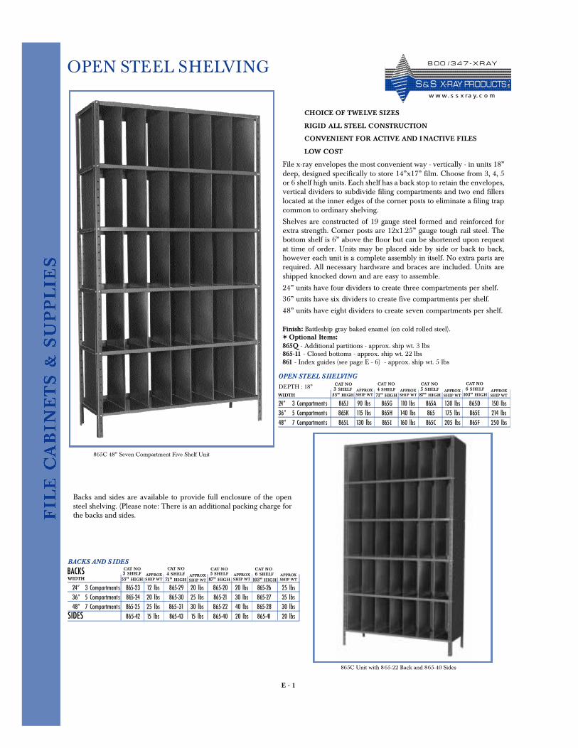
E - 1
OPEN STEEL SHELVING
File x-ray envelopes the most convenient way - vertically - in units 18”deep, designed specifically to store 14”x17” film. Choose from 3, 4, 5or 6 shelf high units. Each shelf has a back stop to retain the envelopes,vertical dividers to subdivide filing compartments and two end fillerslocated at the inner edges of the corner posts to eliminate a filing trapcommon to ordinary shelving.
Shelves are constructed of 19 gauge steel formed and reinforced forextra strength. Corner posts are 12x1.25” gauge tough rail steel. Thebottom shelf is 6” above the floor but can be shortened upon requestat time of order. Units may be placed side by side or back to back,however each unit is a complete assembly in itself. No extra parts arerequired. All necessary hardware and braces are included. Units areshipped knocked down and are easy to assemble.
24” units have four dividers to create three compartments per shelf.
36” units have six dividers to create five compartments per shelf.
48” units have eight dividers to create seven compartments per shelf.
Finish: Battleship gray baked enamel (on cold rolled steel).✶ Optional Items:865Q - Additional partitions - approx. ship wt. 3 lbs 865-11 - Closed bottoms - approx. ship wt. 22 lbs 861 - Index guides (see page E - 6) - approx. ship wt. 5 lbs
CHOICE OF TWELVE SIZES
RIGID ALL STEEL CONSTRUCTION
CONVENIENT FOR ACTIVE AND I NACTIVE FILES
LOW COST
OPEN STEEL SHELVING
DEPTH : 18”
24” 3 Compartments 865J 90 lbs 865G 110 lbs 865A 130 lbs 865D 150 lbs36” 5 Compartments 865K 115 lbs 865H 140 lbs 865 175 lbs 865E 214 lbs48” 7 Compartments 865L 130 lbs 865I 160 lbs 865C 205 lbs 865F 250 lbs
WIDTH3 SHELF55” HIGH
APPROXSHIP WT
865C 48” Seven Compartment Five Shelf Unit
Backs and sides are available to provide full enclosure of the opensteel shelving. (Please note: There is an additional packing charge forthe backs and sides.
4 SHELF71” HIGH
APPROXSHIP WT
5 SHELF87” HIGH
APPROXSHIP WT
6 SHELF103” HIGH
APPROXSHIP WT
BACKS AND S IDES
BACKS
24” 3 Compartments 865-23 12 lbs 865-29 20 lbs 865-20 20 lbs 865-26 25 lbs36” 5 Compartments 865-24 20 lbs 865-30 25 lbs 865-21 30 lbs 865-27 35 lbs48” 7 Compartments 865-25 25 lbs 865-31 30 lbs 865-22 40 lbs 865-28 30 lbs
SIDES 865-42 15 lbs 865-43 15 lbs 865-40 20 lbs 865-41 20 lbs
WIDTH3 SHELF55” HIGH
APPROXSHIP WT
4 SHELF71” HIGH
APPROXSHIP WT
5 SHELF87” HIGH
APPROXSHIP WT
6 SHELF103” HIGH
APPROXSHIP WT
865C Unit with 865-22 Back and 865-40 Sides
CAT NO CAT NO CAT NO CAT NO
CAT NO CAT NO CAT NO CAT NO
8 0 0 / 3 4 7 - X R AY
S & S X- R AY PR O D UCTSw w w. s s x ra y. c o m
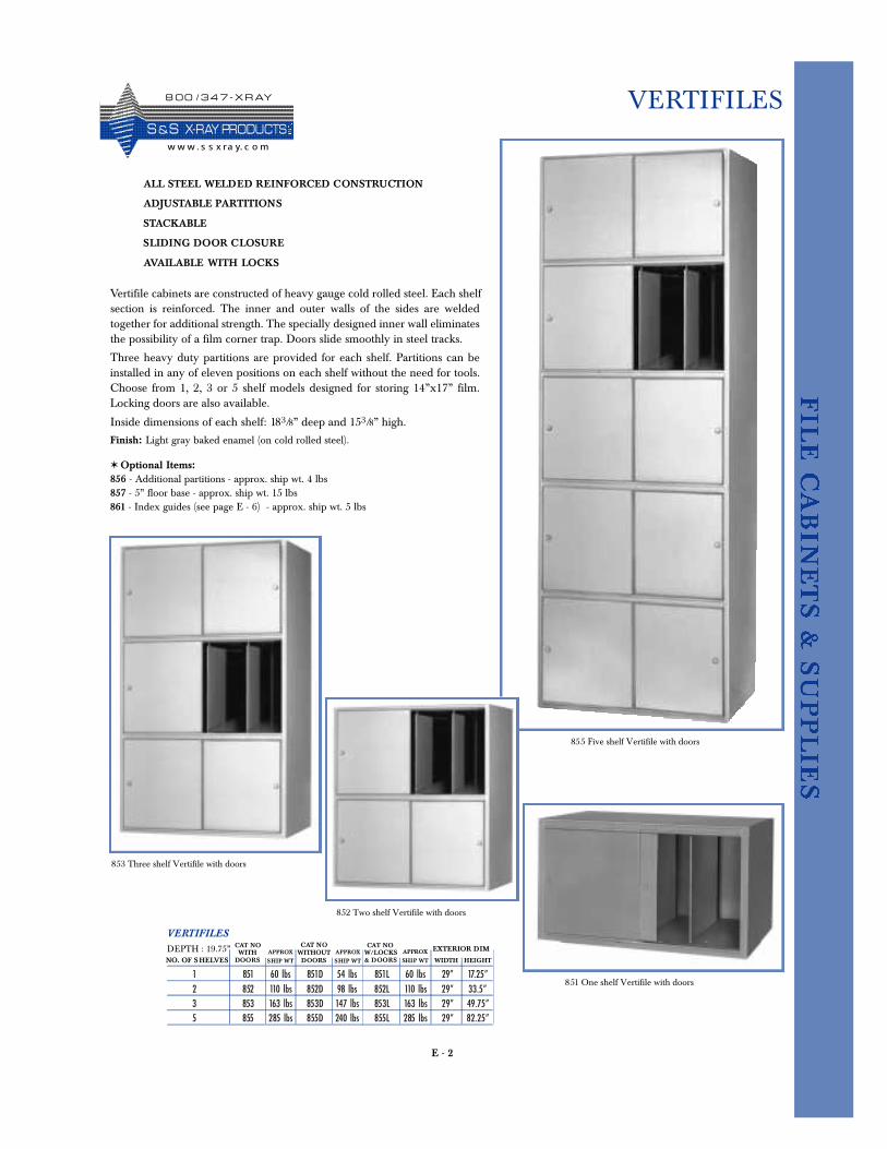
E - 2
VERTIFILES
Vertifile cabinets are constructed of heavy gauge cold rolled steel. Each shelfsection is reinforced. The inner and outer walls of the sides are weldedtogether for additional strength. The specially designed inner wall eliminatesthe possibility of a film corner trap. Doors slide smoothly in steel tracks.
Three heavy duty partitions are provided for each shelf. Partitions can beinstalled in any of eleven positions on each shelf without the need for tools.Choose from 1, 2, 3 or 5 shelf models designed for storing 14”x17” film.Locking doors are also available.
Inside dimensions of each shelf: 183/8” deep and 153/8” high.
ALL STEEL WELDED REINFORCED CONSTRUCTION
ADJUSTABLE PARTITIONS
STACKABLE
SLIDING DOOR CLOSURE
AVAILABLE WITH LOCKS
VERTIFILES
DEPTH : 19.75”
1 851 60 lbs 851D 54 lbs 851L 60 lbs 29” 17.25”2 852 110 lbs 852D 98 lbs 852L 110 lbs 29” 33.5”3 853 163 lbs 853D 147 lbs 853L 163 lbs 29” 49.75”5 855 285 lbs 855D 240 lbs 855L 285 lbs 29” 82.25”
NO. OF SHELVESWITH
DOORSAPPROX
SHIP WTWITHOUTDOORS
APPROX
SHIP WTW/LOCKS& DOORS
APPROX
SHIP WT WIDTH HEIGHT
Finish: Light gray baked enamel (on cold rolled steel).
✶ Optional Items:856 - Additional partitions - approx. ship wt. 4 lbs 857 - 5” floor base - approx. ship wt. 15 lbs 861 - Index guides (see page E - 6) - approx. ship wt. 5 lbs
EXTERIOR DIM
855 Five shelf Vertifile with doors
851 One shelf Vertifile with doors
852 Two shelf Vertifile with doors
853 Three shelf Vertifile with doors
CAT NO CAT NO CAT NO
8 0 0 / 3 4 7 - X R AY
S &S X- R AY PR O D UCTSw w w . s s x ra y. c o m
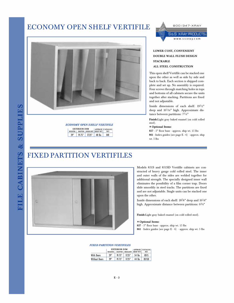
E - 3
ECONOMY OPEN SHELF VERTIFILE
This open shelf Vertifile can be stacked oneupon the other as well as side by side andback to back. Each section is shipped com-plete and set up. No assembly is required.Four screws through matching holes in topsand bottoms of all cabinets secure the unitstogether after stacking. Partitions are fixedand not adjustable.
Inside dimensions of each shelf: 191/2”deep and 161/16” high. Approximate dis-tance between partitions: 71/4”
LOWER COST, CONVENIENT
DOUBLE WALL FLUSH DESIGN
STACKABLE
ALL STEEL CONSTRUCTION
Finish:Light gray baked enamel (on cold rolledsteel).✶ Optional Items:857 - 5” floor base - approx. ship wt. 15 lbs 861 - Index guides (see page E - 6) - approx. shipwt. 5 lbs
ECONOMY OPEN S HELF VERTIFILE
29” 19.75” 17.25” 48 lbs 841
APPROXSHIP WTWIDTH DEPTH
EXTERIOR DIMHEIGHT
CATALOGNO
FIXED PARTITION VERTIFILES
Models 851S and 851SD Vertifile cabinets are con-structed of heavy gauge cold rolled steel. The innerand outer walls of the sides are welded together foradditional strength. The specially designed inner walleliminates the possibility of a film corner trap. Doorsslide smoothly in steel tracks. The partitions are fixedand are not adjustable. Single units can be stacked oneupon the other.
Inside dimensions of each shelf: 187/8” deep and 161/8”high. Approximate distance between partitions: 63/4”
FIXED PARTITION VERTIFILES
With Doors 29” 19.75” 17.25” 54 lbs 851SWithout Doors 29” 19.75” 17.25” 44 lbs 851SD
APPROXSHIP WTWIDTH DEPTH
Finish:Light gray baked enamel (on cold rolled steel).
✶ Optional Items:857 - 5” floor base - approx. ship wt. 15 lbs 861 - Index guides (see page E - 6) - approx. ship wt. 5 lbs
EXTERIOR DIMHEIGHT
CATALOGNO
8 0 0 / 3 4 7 - X R AY
S & S X- R AY PR O D UCTSw w w. s s x ra y. c o m
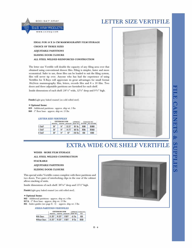
E - 4
LETTER SIZE VERTIFILE
EXTRA WIDE ONE SHELF VERTIFILE
This special wider Vertifile comes complete with three partitions andtwo doors. Two pairs of interlocking clips in the rear of the cabinetallows stacking of units.
Inside dimensions of each shelf: 183/16” deep and 151/2” high.
FIXED PARTITION VERTIFILES
With Doors 31.375” 19.375” 17.875” 65 lbs 850Without Doors 31.375” 19.375” 17.875” 59 lbs 850D
APPROXSHIP WTWIDTH DEPTH
Finish:Light gray baked enamel (on cold rolled steel).
✶ Optional Items:862 - Additional partitions - approx. ship wt. 4 lbs 857A - 5” floor base - approx. ship wt. 15 lbs 861 - Index guides (see page E - 6) - approx. ship wt. 5 lbs
EXTERIOR DIMHEIGHT
CATALOGNO
WIDER - MORE FILM STORAGE
ALL STEEL WELDED CONSTRUCTION
STACKABLE
ADJUSTABLE PARTITIONS
SLIDING DOOR CLOSURE
The letter size Vertifile will double the capacity of any filing area over thatobtained using conventional drawer files. Filing is simpler, faster and moreeconomical. Safer to use, these files can be loaded to suit the filing system,files will never tip over. Anyone who has had the experience of usingVertifiles for X-Rays will appreciate its great advantages for small format18x24cm mammography film, letters, records files and 8 x 10 film. Twodoors and three adjustable partitions are furnished for each shelf.
Inside dimensions of each shelf: 281/4” wide, 123/4” deep and 93/4” high.
IDEAL FOR 18 X 24 CM MAMMOGRAPHY FILM STORAGE
CHOICE OF THREE SIZES
ADJUSTABLE PARTITIONS
SLIDING DOOR CLOSURE
ALL STEEL WELDED REINFORCED CONSTRUCTION
Finish:Light gray baked enamel (on cold rolled steel).
✶ Optional Items:859 - Additional partitions - approx. ship wt. 3 lbs 860 - 5” floor base - approx. ship wt. 15 lbs
LETTER SIZE VERTIFILES
3 Shelf 30” 14” 33.25” 101 lbs 858B 858BD5 Shelf 30” 14” 54.75” 160 lbs 858A 858AD8 Shelf 30” 14” 87” 250 lbs 858 858D
APPROXSHIP WTWIDTH DEPTH
EXTERIOR DIMHEIGHT
CATALOG NODOORS NO DOORS
8 0 0 / 3 4 7 - X R AY
S &S X- R AY PR O D UCTSw w w. s s x ra y. c o m
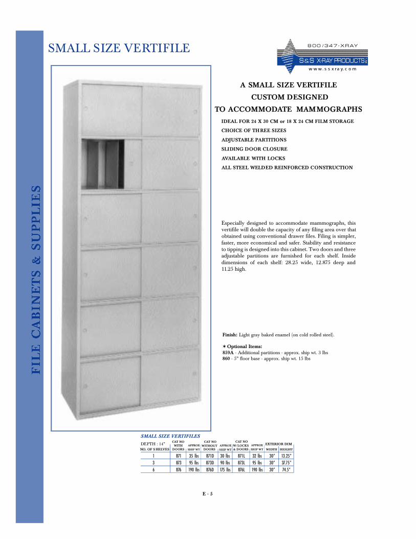
E - 5
SMALL SIZE VERTIFILE
Especially designed to accommodate mammographs, thisvertifile will double the capacity of any filing area over thatobtained using conventional drawer files. Filing is simpler,faster, more economical and safer. Stability and resistanceto tipping is designed into this cabinet. Two doors and threeadjustable partitions are furnished for each shelf. Insidedimensions of each shelf: 28.25 wide, 12.875 deep and11.25 high.
IDEAL FOR 24 X 30 CM or 18 X 24 CM FILM STORAGE
CHOICE OF THREE SIZES
ADJUSTABLE PARTITIONS
SLIDING DOOR CLOSURE
AVAILABLE WITH LOCKS
ALL STEEL WELDED REINFORCED CONSTRUCTION
SMALL SIZE VERTIFILES
DEPTH : 14”
1 871 35 lbs 871D 30 lbs 871L 32 lbs 30” 13.25”3 873 95 lbs 873D 90 lbs 873L 95 lbs 30” 37.75”6 876 190 lbs 876D 175 lbs 876L 190 lbs 30” 74.5”
NO. OF S HELVESWITH
DOORSAPPROX
SHIP WTWITHOUTDOORS
APPROX
SHIP WTW/LOCKS& DOORS
APPROX
SHIP WT WIDTH HEIGHT
Finish: Light gray baked enamel (on cold rolled steel).
✶ Optional Items:859A - Additional partitions - approx. ship wt. 3 lbs 860 - 5” floor base - approx. ship wt. 15 lbs
EXTERIOR DIM
A SMALL SIZE VERTIFILE
CUSTOM DESIGNED
TO ACCOMMODATE MAMMOGRAPHS
CAT NOCAT NO CAT NO
8 0 0 / 3 4 7 - X R AY
S & S X- R AY PR O D UCTSw w w. s s x ra y. c o m
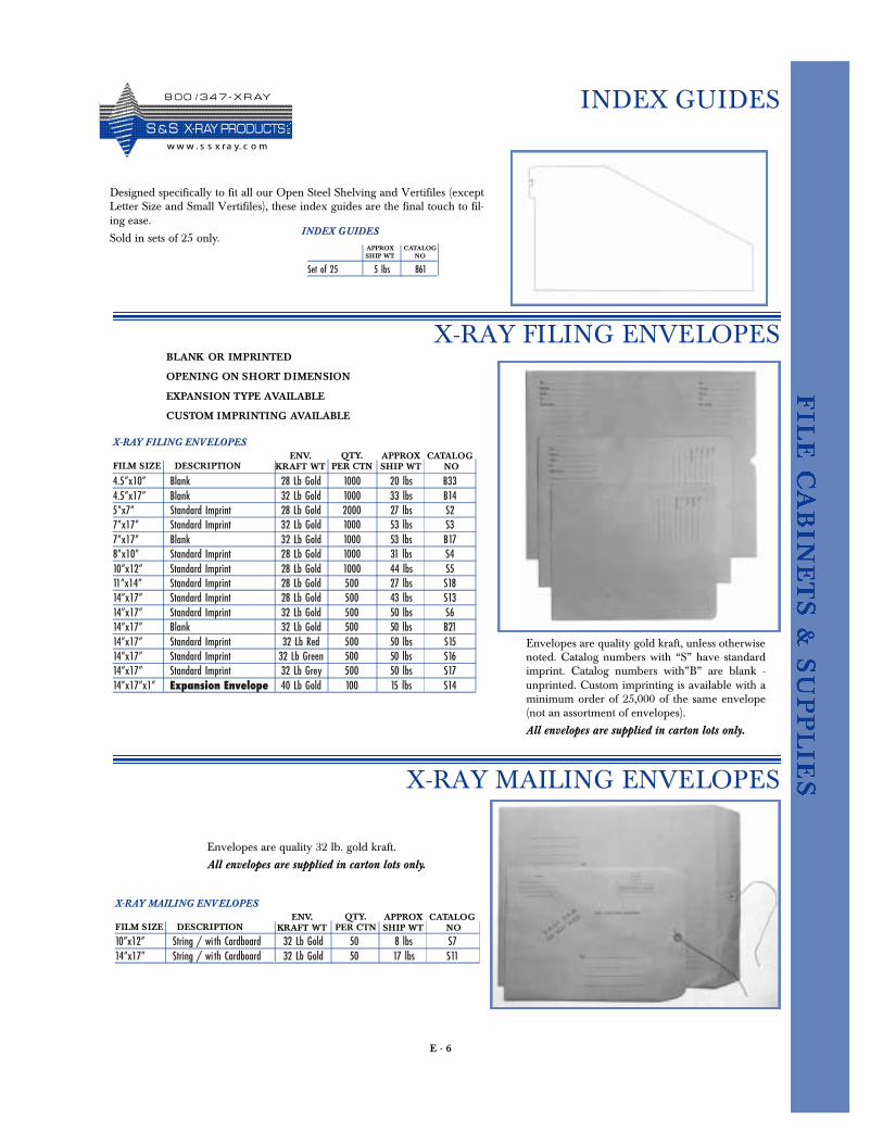
E - 6
Designed specifically to fit all our Open Steel Shelving and Vertifiles (exceptLetter Size and Small Vertifiles), these index guides are the final touch to fil-ing ease.
Sold in sets of 25 only.INDEX GUIDES
Set of 25 5 lbs 861
APPROXSHIP WT
CATALOGNO
INDEX GUIDES
X-RAY MAILING ENVELOPES
Envelopes are quality gold kraft, unless otherwisenoted. Catalog numbers with “S” have standardimprint. Catalog numbers with”B” are blank -unprinted. Custom imprinting is available with aminimum order of 25,000 of the same envelope(not an assortment of envelopes).
All envelopes are supplied in carton lots only.
X-RAY FILING ENVELOPES
4.5”x10” Blank 28 Lb Gold 1000 20 lbs B334.5”x17” Blank 32 Lb Gold 1000 33 lbs B145”x7” Standard Imprint 28 Lb Gold 2000 27 lbs S27”x17” Standard Imprint 32 Lb Gold 1000 53 lbs S37”x17” Blank 32 Lb Gold 1000 53 lbs B178”x10” Standard Imprint 28 Lb Gold 1000 31 lbs S410”x12” Standard Imprint 28 Lb Gold 1000 44 lbs S511”x14” Standard Imprint 28 Lb Gold 500 27 lbs S1814”x17” Standard Imprint 28 Lb Gold 500 43 lbs S1314”x17” Standard Imprint 32 Lb Gold 500 50 lbs S614”x17” Blank 32 Lb Gold 500 50 lbs B2114”x17” Standard Imprint 32 Lb Red 500 50 lbs S1514”x17” Standard Imprint 32 Lb Green 500 50 lbs S1614”x17” Standard Imprint 32 Lb Grey 500 50 lbs S1714”x17”x1” Expansion Envelope 40 Lb Gold 100 15 lbs S14
FILM SIZE DESCRIPTIONCATALOG
NO
BLANK OR IMPRINTED
OPENING ON SHORT DIMENSION
EXPANSION TYPE AVAILABLE
CUSTOM IMPRINTING AVAILABLE
ENV.KRAFT WT
QTY.PER CTN
APPROXSHIP WT
Envelopes are quality 32 lb. gold kraft.
All envelopes are supplied in carton lots only.
X-RAY MAILING ENVELOPES
10”x12” String / wi th Cardboard 32 Lb Gold 50 8 lbs S714”x17” String / wi th Cardboard 32 Lb Gold 50 17 lbs S11
FILM SIZE DESCRIPTIONCATALOG
NOENV.
KRAFT WTQTY.
PER CTNAPPROXSHIP WT
X-RAY FILING ENVELOPES
8 0 0 / 3 4 7 - X R AY
S &S X- R AY PR O D UCTSw w w . s s x ra y. c o m
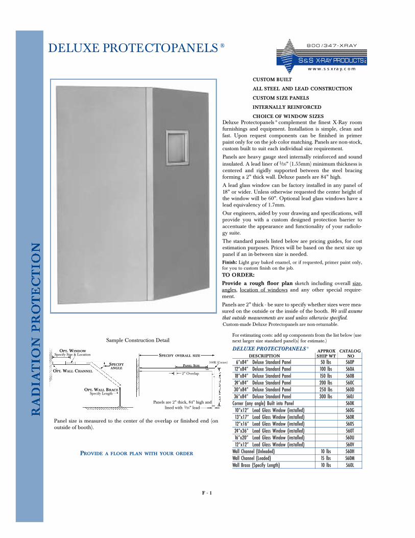
F - 1
DELUXE PROTECTOPANELS ®
Deluxe Protectopanels ® complement the finest X-Ray roomfurnishings and equipment. Installation is simple, clean andfast. Upon request components can be finished in primerpaint only for on the job color matching. Panels are non-stock,custom built to suit each individual size requirement.
Panels are heavy gauge steel internally reinforced and soundinsulated. A lead liner of 1/16” (1.55mm) minimum thickness iscentered and rigidly supported between the steel bracingforming a 2” thick wall. Deluxe panels are 84” high.
A lead glass window can be factory installed in any panel of18” or wider. Unless otherwise requested the center height ofthe window will be 60”. Optional lead glass windows have alead equivalency of 1.7mm.
Our engineers, aided by your drawing and specifications, willprovide you with a custom designed protection barrier toaccentuate the appearance and functionality of your radiolo-gy suite.
The standard panels listed below are pricing guides, for costestimation purposes. Prices will be based on the next size uppanel if an in-between size is needed.
DELUXE PROTECTOPANELS ®
6”x84” Deluxe Standard Panel 50 lbs 560P12”x84” Deluxe Standard Panel 100 lbs 560A18”x84” Deluxe Standard Panel 150 lbs 560B24”x84” Deluxe Standard Panel 200 lbs 560C30”x84” Deluxe Standard Panel 250 lbs 560D36”x84” Deluxe Standard Panel 300 lbs 560JCorner (any angle) Built into Panel 560K10”x12” Lead Glass Window (installed) 560G13”x17” Lead Glass Window (installed) 560R12”x16” Lead Glass Window (installed) 560S24”x36” Lead Glass Window (installed) 560T16”x20” Lead Glass Window (installed) 560U12”x12” Lead Glass Window (installed) 560V
Wall Channel (Unleaded) 10 lbs 560HWall Channel (Leaded) 15 lbs 560MWall Brace (Specify Length) 10 lbs 560L
DESCRIPTIONAPPROXSHIP WT
CATALOGNO
Finish: Light gray baked enamel, or if requested, primer paint only,for you to custom finish on the job.
CUSTOM BUILT
ALL STEEL AND LEAD CONSTRUCTION
CUSTOM SIZE PANELS
INTERNALLY REINFORCED
CHOICE OF WINDOW SIZES
TO ORDER:
Provide a rough floor plan sketch including overall size,angles, location of windows and any other special require-ment.
Panels are 2” thick - be sure to specify whether sizes were mea-sured on the outside or the inside of the booth. We will assumethat outside measurements are used unless otherwise specified.
For estimating costs: add up components from the list below (usenext larger size standard panel(s) for estimate.)
OPT. WINDOWSpecify Size & Location
OPT. WALL BRACESpecify Length
SPECIFYANGLE
OPT. WALL CHANNEL
Sample Construction Detail
Panels are 2” thick, 84” high andlined with 1/16” lead
SPECIFY OVERALL SIZE
2” Overlap
560K (Corner)PANEL SIZE
Panel size is measured to the center of the overlap or finished end (onoutside of booth).
PROVIDE A FLOOR PLAN WITH YOUR ORDER
Custom-made Deluxe Protectopanels are non-returnable.
8 0 0 / 3 4 7 - X R AY
S & S X- R AY PR O D UCTSw w w. s s x ra y. c o m
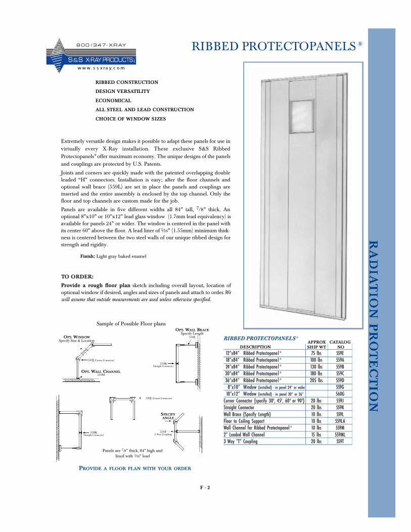
F - 2
RIBBED PROTECTOPANELS ®
Extremely versatile design makes it possible to adapt these panels for use invirtually every X-Ray installation. These exclusive S&S RibbedProtectopanels® offer maximum economy. The unique designs of the panelsand couplings are protected by U.S. Patents.
Joints and corners are quickly made with the patented overlapping doubleleaded “H” connectors. Installation is easy; after the floor channels andoptional wall brace (559L) are set in place the panels and couplings areinserted and the entire assembly is enclosed by the top channel. Only thefloor and top channels are custom made for the job.
Panels are available in five different widths all 84” tall, 7/8” thick. Anoptional 8”x10” or 10”x12” lead glass window (1.7mm lead equivalency) isavailable for panels 24” or wider. The window is centered in the panel withits center 60” above the floor. A lead liner of 1/16” (1.55mm) minimum thick-ness is centered between the two steel walls of our unique ribbed design forstrength and rigidity.
RIBBED CONSTRUCTION
DESIGN VERSATILITY
ECONOMICAL
ALL STEEL AND LEAD CONSTRUCTION
CHOICE OF WINDOW SIZES
RIBBED PROTECTOPANELS ®
12”x84” Ribbed Protectopanel® 75 lbs 559E18”x84” Ribbed Protectopanel® 100 lbs 559A24”x84” Ribbed Protectopanel® 130 lbs 559B30”x84” Ribbed Protectopanel® 180 lbs 559C36”x84” Ribbed Protectopanel® 205 lbs 559D8”x10” Window (installed) - in panel 24” or wider 559G
10”x12” Window (installed) - in panel 30” or 36” 560GCorner Connector (specify 300, 450, 600 or 900) 20 lbs 559JStraight Connector 20 lbs 559KWall Brace (Specify Length) 10 lbs 559LFloor to Ceiling Support 10 lbs 559LAWall Channel for Ribbed Protectopanel® 10 lbs 559M2” Leaded Wall Channel 15 lbs 559ML3 Way “T” Coupling 20 lbs 559T
DESCRIPTIONAPPROXSHIP WT
CATALOGNO
Finish: Light gray baked enamel
TO ORDER:
Provide a rough floor plan sketch including overall layout, location ofoptional window if desired, angles and sizes of panels and attach to order.Wewill assume that outside measurements are used unless otherwise specified.
Sample of Possible Floor plans
OPT. WINDOWSpecify Size & Location
OPT. WALL BRACESpecify Length
559L
SPECIFYANGLE
OPT. WALL CHANNEL559M
Panels are 7/8” thick, 84” high andlined with 1/16” lead
559K (Straight Connector)
559J (Corner Connector)
559J (Corner Connector)
PROVIDE A FLOOR PLAN WITH YOUR ORDER
559T (3 Way Coupling)
559K (Straight Connector)
8 0 0 / 3 4 7 - X R AY
S &S X- R AY PR O D UCTSw w w . s s x ra y. c o m
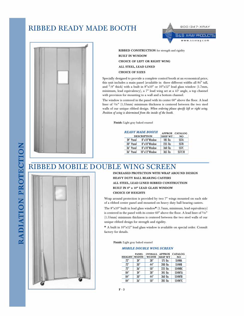
F - 3
RIBBED READY MADE BOOTH
Specially designed to provide a complete control booth at an economical price,this unit includes a main panel (available in three different widths all 84” tall,and 7/8” thick) with a built in 8”x10” or 10”x12” lead glass window (1.7mm,minimum, lead equivalency), a 7” lead wing set at a 450 angle, a top channelwith provision for mounting to a wall and a bottom channel.
The window is centered in the panel with its center 60” above the floor. A leadliner of 1/16” (1.55mm) minimum thickness is centered between the two steelwalls of our unique ribbed design. When ordering please specify left or right wing.Position of wing is determined from the inside of the booth.
READY MADE BOOTH
24” Panel 8”x10”Window 185 lbs 557A30” Panel 8”x10”Window 235 lbs 557B36” Panel 8”x10”Window 360 lbs 557C36” Panel 10”x12”Window 365 lbs 557C10
DESCRIPTIONAPPROXSHIP WT
CATALOGNO
Finish: Light gray baked enamel
RIBBED CONSTRUCTION for strength and rigidity
BUILT IN WI NDOW
CHOICE OF LEFT OR RIGHT WING
ALL STEEL, LEAD LINED
CHOICE OF SIZES
RIBBED MOBILE DOUBLE WING SCREEN
Wrap around protection is provided by two 7” wings mounted on each sideof a ribbed center panel and mounted on heavy duty ball bearing casters.
The 8”x10” built in lead glass window* (1.7mm, minimum, lead equivalency)is centered in the panel with its center 60” above the floor. A lead liner of 1/16”(1.55mm) minimum thickness is centered between the two steel walls of ourunique ribbed design for strength and rigidity.
* A built in 10”x12” lead glass window is available on special order. Consultfactory for details.
MOBILE DOUBLE WING SCREEN
72” 24” 38” 175 lbs 554WA72” 30” 44” 200 lbs 554WB72” 36” 50” 225 lbs 554WBC84” 24” 38” 245 lbs 554WTA84” 30” 44” 260 lbs 554WTB84” 36” 50” 285 lbs 554WTC
HEIGHT WIDTH WI DTHAPPROXSHIP WT
CATALOGNO
Finish: Light gray baked enamel
INCREASED PROTECTION WITH WRAP AROUND DESIGN
HEAVY DUTY BALL BEARING CASTERS
ALL STEEL, LEAD LINED RIBBED CONSTRUCTION
BUILT IN 8” x 10” LEAD GLASS WINDOW
CHOICE OF HEIGHTS
OVERALLPANEL
8 0 0 / 3 4 7 - X R AY
S & S X- R AY PR O D UCTSw w w. s s x ra y. c o m
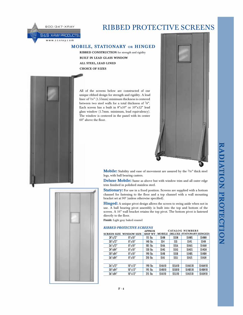
F - 4
RIBBED PROTECTIVE SCREENS
Mobile: Stability and ease of movement are assured by the 3/16” thick steellegs, with ball bearing casters.
Deluxe Mobile: Same as above but with window trim and all outer edgetrim finished in polished stainless steel.
Stationary: For use in a fixed position. Screens are supplied with a bottomchannel for fastening to the floor and a top channel with a wall mountingbracket set at 900 (unless otherwise specified).
Hinged: A unique pivot design allows the screen to swing aside when not inuse. A ball bearing pivot assembly is built into the top and bottom of thescreen. A 16” wall bracket retains the top pivot. The bottom pivot is fasteneddirectly to the floor.
RIBBED CONSTRUCTION for strength and rigidity
BUILT IN LEAD GLASS WINDOW
ALL STEEL, LEAD LINED
CHOICE OF S IZES
MOBILE, STAT IONA RY OR HINGED
Finish: Light gray baked enamel
RIBBED PROTECTIVE SCREENS
24”x72” 8”x10” 115 lbs 554N 555N 554NS 554NH30”x72” 8”x10” 140 lbs 554 555 554S 554H36”x72” 8”x10” 185 lbs 554A 555A 554AS 554AH24”x84” 8”x10” 130 lbs 554G 555G 554GS 554GH30”x84” 8”x10” 190 lbs 554B 555B 554BS 554BH36”x84” 8”x10” 210 lbs 554J 555J 554JS 554JH
36”x72” 10”x12” 190 lbs 554A10 555A10 554AS10 554AH1030”x84” 10”x12” 195 lbs 554B10 555B10 554BS10 554BH1036”x84” 10”x12” 215 lbs 554J10 555J10 554JS10 554JH10
SCREEN SIZE WINDOW SIZEAPPROXSHIP WT MOBILE DELUXE STATIONARY HINGED
CATA LOG N UM BER S
All of the screens below are constructed of ourunique ribbed design for strength and rigidity. A leadliner of 1/16” (1.55mm) minimum thickness is centeredbetween two steel walls for a total thickness of 7/8”.Each screen has a built in 8”x10” or 10”x12” leadglass window (1.7mm. minimum, lead equivalency).The window is centered in the panel with its center60” above the floor.
8 0 0 / 3 4 7 - X R AY
S &S X- R AY PR O D UCTSw w w. s s x ra y. c o m
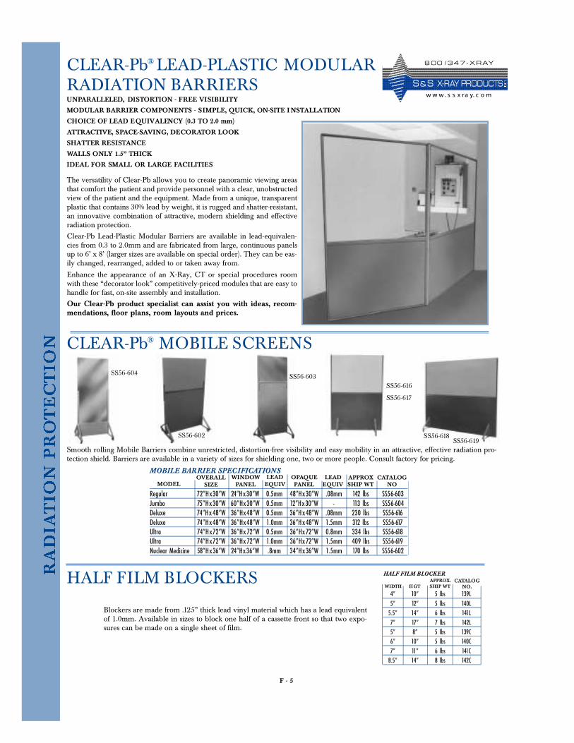
F - 5
CLEAR-Pb® LEAD-PLASTIC MODULAR RADIATION BARRIERSUNPARALLELED, DISTORTION - FREE VISIBILITY
MODULAR BARRIER COMPONENTS - SIMPLE, QUICK, ON-SITE I NSTALLATION
CHOICE OF LEAD EQUIVALENCY (0.3 TO 2.0 mm)
ATTRACTIVE, SPACE-SAVING, DECORATOR LOOK
SHATTER RESISTANCE
WALLS ONLY 1.5” THICK
IDEAL FOR SMALL OR LARGE FACILITIES
The versatility of Clear-Pb allows you to create panoramic viewing areasthat comfort the patient and provide personnel with a clear, unobstructedview of the patient and the equipment. Made from a unique, transparentplastic that contains 30% lead by weight, it is rugged and shatter-resistant,an innovative combination of attractive, modern shielding and effectiveradiation protection.
Clear-Pb Lead-Plastic Modular Barriers are available in lead-equivalen-cies from 0.3 to 2.0mm and are fabricated from large, continuous panelsup to 6’ x 8’ (larger sizes are available on special order). They can be eas-ily changed, rearranged, added to or taken away from.
Enhance the appearance of an X-Ray, CT or special procedures roomwith these “decorator look” competitively-priced modules that are easy tohandle for fast, on-site assembly and installation.
Our Clear-Pb product specialist can assist you with ideas, recom-mendations, floor plans, room layouts and prices.
MOBILE BARRIER SPECIFICATIONS
Regular 72”Hx30”W 24”Hx30”W 0.5mm 48”Hx30”W .08mm 142 lbs SS56-603Jumbo 75”Hx30”W 60”Hx30”W 0.5mm 12”Hx30”W - 113 lbs SS56-604Deluxe 74”Hx48”W 36”Hx48”W 0.5mm 36”Hx48”W .08mm 230 lbs SS56-616Deluxe 74”Hx48”W 36”Hx48”W 1.0mm 36”Hx48”W 1.5mm 312 lbs SS56-617Ultra 74”Hx72”W 36”Hx72”W 0.5mm 36”Hx72”W 0.8mm 334 lbs SS56-618Ultra 74”Hx72”W 36”Hx72”W 1.0mm 36”Hx72”W 1.5mm 409 lbs SS56-619Nuclear Medicine 58”Hx36”W 24”Hx36”W .8mm 34”Hx36”W 1.5mm 170 lbs SS56-602
APPROXSHIP WT
LEADEQUIV
CATALOGNO
CLEAR-Pb® MOBILE SCREENS
Smooth rolling Mobile Barriers combine unrestricted, distortion-free visibility and easy mobility in an attractive, effective radiation pro-tection shield. Barriers are available in a variety of sizes for shielding one, two or more people. Consult factory for pricing.
MODELLEADEQUIV
OPAQUEPANEL
WINDOWPANEL
OVERALLSIZE
HALF FILM BLOCKER
4” 10” 5 lbs 139L5” 12” 5 lbs 140L5.5” 14” 6 lbs 141L7” 17” 7 lbs 142L5” 8” 5 lbs 139C6” 10” 5 lbs 140C7” 11” 6 lbs 141C8.5” 14” 8 lbs 142C
WIDTH HGT SHIP WTAPPROX. CATALOG
NO.HALF FILM BLOCKERS
Blockers are made from .125” thick lead vinyl material which has a lead equivalentof 1.0mm. Available in sizes to block one half of a cassette front so that two expo-sures can be made on a single sheet of film.
SS56-603SS56-604
SS56-616
SS56-617
SS56-618SS56-619
SS56-602
8 0 0 / 3 4 7 - X R AY
S & S X- R AY PR O D UCTSw w w. s s x ra y. c o m
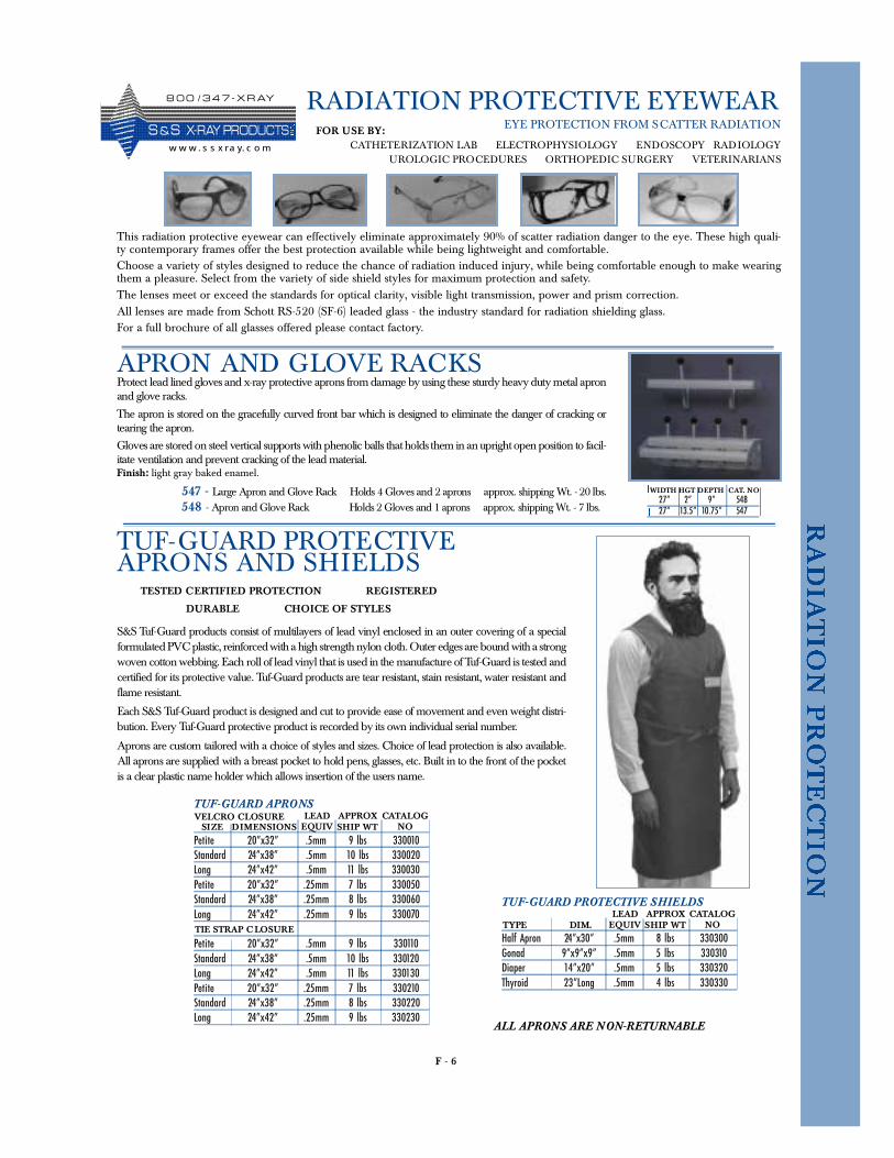
F - 6
RADIATION PROTECTIVE EYEWEAR
TUF-GUARD PROTECTIVE SHIELDS
Half Apron 24”x30” .5mm 8 lbs 330300Gonad 9”x9”x9” .5mm 5 lbs 330310Diaper 14”x20” .5mm 5 lbs 330320Thyroid 23”Long .5mm 4 lbs 330330
APPROXSHIP WT
LEADEQUIV
CATALOGNOTYPE DIM.
This radiation protective eyewear can effectively eliminate approximately 90% of scatter radiation danger to the eye. These high quali-ty contemporary frames offer the best protection available while being lightweight and comfortable.Choose a variety of styles designed to reduce the chance of radiation induced injury, while being comfortable enough to make wearingthem a pleasure. Select from the variety of side shield styles for maximum protection and safety.The lenses meet or exceed the standards for optical clarity, visible light transmission, power and prism correction.All lenses are made from Schott RS-520 (SF-6) leaded glass - the industry standard for radiation shielding glass.For a full brochure of all glasses offered please contact factory.
EYE PROTECTION FROM SCATTER RADIATION
TUF-GUARD PROTECTIVEAPRONS AND SHIELDS
TESTED CERTIFIED PROTECTION REGISTERED
DURABLE CHOICE OF STYLES
S&S Tu f -Guard products consist of multilayers of lead vinyl enclosed in an outer covering of a specialformulated PVC plastic, reinforced with a high strength nylon cloth. Outer edges are bound with a strongwoven cotton webbing. Each roll of lead vinyl that is used in the manufacture of Tu f -Guard is tested andcertified for its protective value. Tu f -Guard products are tear resistant, stain resistant, water resistant andflame resistant.
E a ch S&S Tu f -Guard product is designed and cut to provide ease of movement and even weight distri-bution. Every Tu f -Guard protective product is recorded by its own individual serial number.
Aprons are custom tailored with a choice of styles and sizes. Choice of lead protection is also available.All aprons are supplied with a breast pocket to hold pens, glasses, etc. Built in to the front of the pock e tis a clear plastic name holder which allows insertion of the users name.
TUF-GUARD APRONS
Petite 20”x32” .5mm 9 lbs 330010Standard 24”x38” .5mm 10 lbs 330020Long 24”x42” .5mm 11 lbs 330030Petite 20”x32” .25mm 7 lbs 330050Standard 24”x38” .25mm 8 lbs 330060Long 24”x42” .25mm 9 lbs 330070
Petite 20”x32” .5mm 9 lbs 330110Standard 24”x38” .5mm 10 lbs 330120Long 24”x42” .5mm 11 lbs 330130Petite 20”x32” .25mm 7 lbs 330210Standard 24”x38” .25mm 8 lbs 330220Long 24”x42” .25mm 9 lbs 330230
VELCRO CLOSURE APPROXSHIP WT
LEADEQUIV
CATALOGNO
TIE STRAP C LOSURE
SIZE DIMENSIONS
ALL APRONS ARE NON-RETURNABLE
FOR USE BY:CATHETERIZATION LAB ELECTROPHYSIOLOGY ENDOSCOPY RADIOLOGY
UROLOGIC PROCEDURES ORTHOPEDIC SURGERY VETERINARIANS
APRON AND GLOVE RACKSProtect lead lined gloves and x-ray protective aprons from damage by using these sturdy heavy duty metal apronand glove rack s .
The apron is stored on the gracefully curved front bar which is designed to eliminate the danger of cracking ortearing the apron.
Gloves are stored on steel vertical supports with phenolic balls that holds them in an upright open position to facil-itate ventilation and prevent cracking of the lead material.Finish: light gray baked enamel.
547 - Large Apron and Glove Rack Holds 4 Gloves and 2 aprons approx. shipping Wt. - 20 lbs.548 - Apron and Glove Rack Holds 2 Gloves and 1 aprons approx. shipping Wt. - 7 lbs.
27” 2” 9” 54827” 13.5” 10.75” 547
WIDTH HGT DEPTH CAT. NO
8 0 0 / 3 4 7 - X R AY
S &S X- R AY PR O D UCTSw w w . s s x ra y. c o m
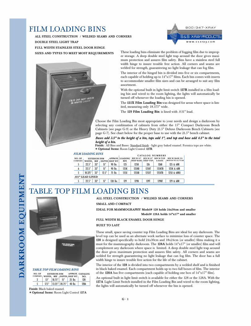
G - 1
FILM LOADING BINS
These loading bins eliminate the problem of fogging film due to improp-er storage. A deep double steel light trap around the door gives maxi-mum protection and assures film safety. Bins have a stainless steel fullwidth hinge to insure trouble free action. All corners and seams arewelded for strength, guaranteeing no light leakage that can fog film.
The interior of the hinged bin is divided into five or six compartments,each capable of holding up to 14”x17” films. Each bin comes with insertsto accommodate smaller film sizes and can be arranged to suit any filmassortment.
With the optional built in light limit switch 127R installed in a film load-ing bin and wired to the room lighting, the lights will automatically beturned off whenever the loading bin is opened.
The 125X Film Loading Bin was designed for areas where space is lim-ited, measuring only 18.375” wide.
The 129 Film Loading Bin is lined with .031” lead.
ALL STEEL CONSTRUCTION / WELDED SEAMS AND CORNERS
DOUBLE STEEL LIGHT TRAP
FULL WIDTH STAINLESS STEEL DOOR HINGE
SIZES AND TYPES TO MEET MOST REQUIREMENTS
TABLE TOP FILM LOADING BINSALL STEEL CONSTRUCTION / WELDED SEAMS AND CORNERS
SMALL AND COMPACT
IDEAL FOR MAMMOGRAPHY Model# 128 holds 24x30cm and smaller
Model# 128A holds 14”x17” and smaller
FULL WIDTH BLACK ENAMEL DOOR HINGE
BUILT TO LAST
Finish: Black baked enamel.✶ Optional Items: Room Light Control 127A
FILM LOADING BINS
5 22.5” 33” 15” 90 lbs 125 125B 126 126B 125 & 68R6 22.5” 33” 15” 90 lbs 125K 125KB 125KT 125KTB 125K & 68R5 18.375” 33” 12.5” 75 lbs 125X 125XB 125XT 125XTB 125X & 68RX
5 22.5” 33” 15” 130 lbs 129 129B 129T 129BT 129 & 68R
NO. OFCOMPART. WIDTH HGT DEPTH SHIP WT
EXTERIOR DIM APPROX.CATA LOG N U M B E RS
BIN W/15”DEEP BASE
LOADINGBIN
BIN W/15”DEEP TOP
BIN W/TOP& BASE
BIN W/BASE TOMATCH TO 21.5”CAB
.031” LEAD LINED
Choose the Film Loading Bin most appropriate to your needs and design a darkroom byselecting any combination of cabinets from either the 15” Compact Darkroom BenchCabinets (see page G-9) or the Heavy Duty 21.5” Deluxe Darkroom Bench Cabinets (seepage G-7). See chart below for the proper base to use with the 21.5” bench cabinet.
Bases add 3.5” to the height of a bin, tops add 1”, and top and base add 4.5” to the totalheight of a bin. Finish: All Bins and Bases: Standard finish - light gray baked enamel. Formica tops are white.✶ Optional Items: Room Light Control 127R
These small, space saving counter top Film Loading Bins are ideal for any darkroom. Thelevel top can be used as an alternate work surface to minimize loss of counter space. The128 is designed specifically to hold 24x30cm and 18x24cm (or smaller) films making it amust for the mammography darkroom. The 128A holds 14”x17” (or smaller) film and willcomplement any darkroom where space is limited. A deep double steel light trap aroundthe door gives maximum protection and assures film safety. All corners and seams arewelded for strength guaranteeing no light leakage that can fog film. The door has a fullwidth hinge to insure trouble free action for the life of the cabinet.
The interior of the 128 is divided into two compartments by a welded shelf and is finishedin black baked enamel. Each compartment holds up to two full boxes of film. The interiorof the 128A has five compartments (each capable of holding one box of 14”x17” film).
An optional built in light limit switch is available for either the 128 or the 128A. With the127A Light Limit Switch installed in the Film Loading Bin and wired to the room lighting,the lights will automatically be turned off whenever the bin is opened.
TABLE TOP FILM LOADING BINS
2 13” 10.75” 15” 25 lbs 1285 17.5” 13.25” 20.75” 40 lbs 128A
NO. OFCOMPART. WIDTH HGT DEPTH SHIP WT
EXTERIOR DIM APPROX. CATALOGNO.
8 0 0 / 3 4 7 - X R AY
S & S X- R AY PR O D UCTSw w w. s s x ra y. c o m
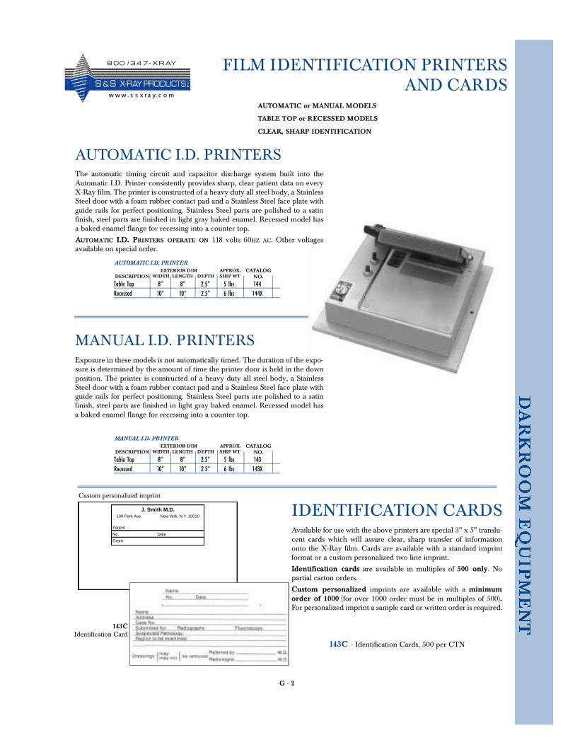
FILM IDENTIFICATION PRINTERSAND CARDS
AUTOMATIC I.D. PRINTER
Table Top 8” 8” 2.5” 5 lbs 144Recessed 10” 10” 2.5” 6 lbs 144X
DESCRIPTION WIDTH LENGTH DEPTH SHIP WTEXTERIOR DIM APPROX. CATALOG
NO.
AUTOMATIC or MANUAL MODELS
TABLE TOP or RECESSED MODELS
CLEAR, SHARP IDENTIFICATION
AUTOMATIC I.D. PRINTERS
MANUAL I.D. PRINTER
Table Top 8” 8” 2.5” 5 lbs 143Recessed 10” 10” 2.5” 6 lbs 143X
DESCRIPTION WIDTH LENGTH DEPTH SHIP WTEXTERIOR DIM APPROX. CATALOG
NO.
MANUAL I.D. PRINTERS
Available for use with the above printers are special 3” x 5” translu-cent cards which will assure clear, sharp transfer of informationonto the X-Ray film. Cards are available with a standard imprintformat or a custom personalized two line imprint.
Identification cards are available in multiples of 500 only. Nopartial carton orders.
Custom personalized imprints are available with a minimumorder of 1000 (for over 1000 order must be in multiples of 500).For personalized imprint a sample card or written order is required.
143C - Identification Cards, 500 per CTN
IDENTIFICATION CARDS
G - 2
Exposure in these models is not automatically timed. The duration of the expo-sure is determined by the amount of time the printer door is held in the downposition. The printer is constructed of a heavy duty all steel body, a StainlessSteel door with a foam rubber contact pad and a Stainless Steel face plate withguide rails for perfect positioning. Stainless Steel parts are polished to a satinfinish, steel parts are finished in light gray baked enamel. Recessed model hasa baked enamel flange for recessing into a counter top.
The automatic timing circuit and capacitor discharge system built into theAutomatic I.D. Printer consistently provides sharp, clear patient data on everyX-Ray film. The printer is constructed of a heavy duty all steel body, a StainlessSteel door with a foam rubber contact pad and a Stainless Steel face plate withguide rails for perfect positioning. Stainless Steel parts are polished to a satinfinish, steel parts are finished in light gray baked enamel. Recessed model hasa baked enamel flange for recessing into a counter top.
AUTOMATIC I.D. PRINTERS OPERATE ON 118 volts 60HZ AC. Other voltagesavailable on special order.
J. Smith M.D.100 Park Ave. New York, N.Y. 10010
Patient
No. Date
Exam.
Custom personalized imprint
143CIdentification Card
8 0 0 / 3 4 7 - X R AY
S &S X- R AY PR O D UCTSw w w . s s x ra y. c o m
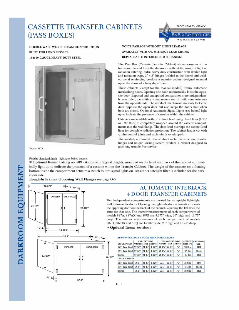
G - 3
CASSETTE TRANSFER CABINETS(PASS BOXES)
The Pass Box (Cassette Transfer Cabinet) allows cassettes to betransferred to and from the darkroom without the worry of light orradiation entering. Extra heavy duty construction with double lightand radiation traps, 2” x 3” hinges (welded to the doors) and weld-ed metal reinforcing produce a superior cabinet designed to standup to the abuse of a busy department.
These cabinets (except for the manual models) feature automaticinterlocking doors. Opening one door automatically locks the oppo-site door. Exposed and unexposed compartments are independent-ly controlled, permitting simultaneous use of both compartmentsfrom the opposite side. The interlock mechanism not only locks thedoor opposite the open door but also keeps the doors shut whenboth are closed. Optional Automatic Signal Lights (see below) lightup to indicate the presence of cassettes within the cabinet.
Cabinets are available with or without lead lining. Lead liner (1/16”or 1/8” thick) is completely wrapped around the cassette compart-ments into the wall flange. The door lead overlaps the cabinet leadliner for complete radiation protection. The cabinet lead is cut witha minimum of joints and each joint is overlapped.
The welded, reinforced, double sheet metal construction, durablehinges and unique locking system produce a cabinet designed togive long trouble free service.
Finish: Standard finish - light gray baked enamel.✶ Optional Items: Catalog no. 889 - Automatic Signal Lights, mounted on the front and back of the cabinet automat-ically light up to indicate the presence of a cassette within the Transfer Cabinet. The weight of the cassette on a floatingbottom inside the compartment actuates a switch to turn signal lights on. An amber safelight filter is included for the dark-room side.Rough-In Frames, Opposing Wall Flanges see page G-5
Shown: 887A
AUTO-INTERLOCK 4 DOOR TRANSFER CABINET
.062” Lead Lined 22.375” 24.187” 18.125” 24.375” 26.187” .75” 240 lbs 887A
.125” Lead Lined 22.375” 24.187” 18.125” 24.375” 26.187” .75” 315 lbs 887AXUnlined 22.375” 24.187” 18.125” 24.375” 26.187” .75” 187 lbs 887B
.062” Lead Lined 35.5” 24.187” 18.125” 37.5” 26.187” .75” 350 lbs 887H
.125” Lead Lined 35.5” 24.187” 18.125” 37.5” 26.187” .75” 425 lbs 887HXUnlined 35.5” 24.187” 18.125” 37.5” 26.187” .75” 260 lbs 887J
DESCRIPTION WI DTH HGT DEPTH SHIP WTCAB. EXT. DIM APPROX. CATALOG
NO.
Two independent compartments are created by an upright light-tightwall between the doors. Opening the right side door automatically sealsthe opposing door on the back of the cabinet. Opening the left does thesame for that side. The interior measurements of each compartment ofmodels 887A, 887AX and 887B are 8.375” wide, 20” high and 16.75”deep. The interior measurements of each compartment of models887H, 887HX and 887J are 14.937” wide, 20” high and 16.75” deep.
DOUBLE WALL WELDED SEAM CONSTRUCTION
BUILT FOR LONG SERVICE
18 & 20 GAUGE HEAVY DUTY STEEL
VOICE PASSAGE WITHOUT LIGHT LEAKAGE
AVAILABLE WITH OR WITHOUT LEAD LINING
REPLACEABLE INTE RLOCK MECHANISM
FLANGE EXT. DIMWIDTH HGT DEPTH
LARGE CABINET
AUTOMATIC INTERLOCK4 DOOR TRANSFER CABINETS
✶ Optional Items: See above
22.375”
26.187”
24.375”
24.187”
.75”
35.5”
26.187”
37.5”
24.187”
.75”
EXPOSED UNEXPOSED
EXPOSED UNEXPOSED
8 0 0 / 3 4 7 - X R AY
S & S X- R AY PR O D UCTSw w w. s s x ra y. c o m
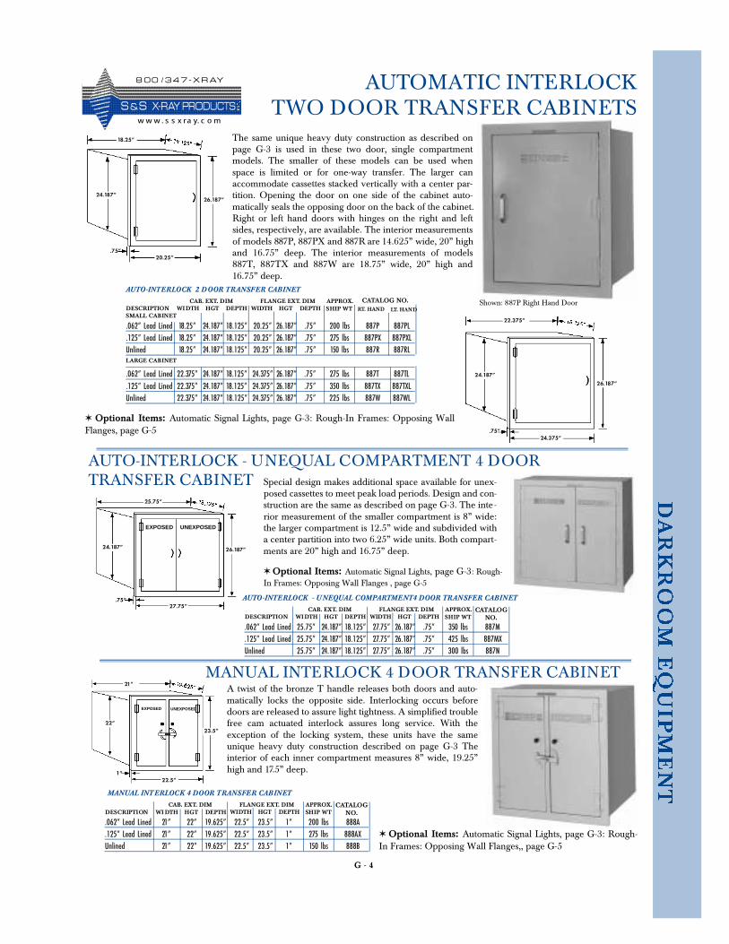
G - 4
AUTOMATIC INTERLOCKTWO DOOR TRANSFER CABINETS
18.25”
26.187”
20.25”
24.187”
.75”
22.375”
26.187”
24.375”
24.187”
.75”
21”
23.5”
22.5”
22”
1”
EXPOSED UNEXPOSED
25.75”
26.187”
27.75”
24.187”
.75”
EXPOSED UNEXPOSED
AUTO-INTERLOCK 2 DOOR TRANSFER CABINET
.062” Lead Lined 18.25” 24.187” 18.125” 20.25” 26.187” .75” 200 lbs 887P 887PL
.125” Lead Lined 18.25” 24.187” 18.125” 20.25” 26.187” .75” 275 lbs 887PX 887PXLUnlined 18.25” 24.187” 18.125” 20.25” 26.187” .75” 150 lbs 887R 887RL
.062” Lead Lined 22.375” 24.187” 18.125” 24.375” 26.187” .75” 275 lbs 887T 887TL
.125” Lead Lined 22.375” 24.187” 18.125” 24.375” 26.187” .75” 350 lbs 887TX 887TXLUnlined 22.375” 24.187” 18.125” 24.375” 26.187” .75” 225 lbs 887W 887WL
DESCRIPTION WI DTH HGT DEPTH SHIP WTCAB. EXT. DIM APPROX. CATALOG NO.
The same unique heavy duty construction as described onpage G-3 is used in these two door, single compartmentmodels. The smaller of these models can be used whenspace is limited or for one-way transfer. The larger canaccommodate cassettes stacked vertically with a center par-tition. Opening the door on one side of the cabinet auto-matically seals the opposing door on the back of the cabinet.Right or left hand doors with hinges on the right and leftsides, respectively, are available. The interior measurementsof models 887P, 887PX and 887R are 14.625” wide, 20” highand 16.75” deep. The interior measurements of models887T, 887TX and 887W are 18.75” wide, 20” high and16.75” deep.
FLANGE EXT. DIMWIDTH HGT DEPTH
LARGE CABINET
.062” Lead Lined 25.75” 24.187” 18.125” 27.75” 26.187” .75” 350 lbs 887M
.125” Lead Lined 25.75” 24.187” 18.125” 27.75” 26.187” .75” 425 lbs 887MXUnlined 25.75” 24.187” 18.125” 27.75” 26.187” .75” 300 lbs 887N
DESCRIPTION WI DTH HGT DEPTH SHIP WTCAB. EXT. DIM APPROX. CATALOG
NO.FLANGE EXT. DIM
WIDTH HGT DEPTH
AUTO-INTERLOCK - UNEQUAL COMPARTMENT 4 DOORTRANSFER CABINET
MANUAL INTERLOCK 4 DOOR TRANSFER CABINET
.062” Lead Lined 21” 22” 19.625” 22.5” 23.5” 1” 200 lbs 888A
.125” Lead Lined 21” 22” 19.625” 22.5” 23.5” 1” 275 lbs 888AXUnlined 21” 22” 19.625” 22.5” 23.5” 1” 150 lbs 888B
DESCRIPTION WI DTH HGT DEPTH SHIP WTCAB. EXT. DIM APPROX. CATALOG
NO.
Special design makes additional space available for unex-posed cassettes to meet peak load periods. Design and con-struction are the same as described on page G-3. The inte -rior measurement of the smaller compartment is 8” wide:the larger compartment is 12.5” wide and subdivided witha center partition into two 6.25” wide units. Both compart-ments are 20” high and 16.75” deep.
FLANGE EXT. DIMWIDTH HGT DEPTH
MANUAL INTERLOCK 4 DOOR TRANSFER CABINETA twist of the bronze T handle releases both doors and auto-matically locks the opposite side. Interlocking occurs beforedoors are released to assure light tightness. A simplified troublefree cam actuated interlock assures long service. With theexception of the locking system, these units have the sameunique heavy duty construction described on page G-3 Theinterior of each inner compartment measures 8” wide, 19.25”high and 17.5” deep.
✶ Optional Items: Automatic Signal Lights, page G-3: Rough-In Frames: Opposing WallFlanges, page G-5
✶ Optional Items: Automatic Signal Lights, page G-3: Rough-In Frames: Opposing Wall Flanges , page G-5
✶ Optional Items: Automatic Signal Lights, page G-3: Rough-In Frames: Opposing Wall Flanges,, page G-5
RT. HAND LT. HANDSMALL CABINET
AUTO-INTERLOCK - U NEQUAL COMPARTMENT4 DOOR TRANSFER CABINET
Shown: 887P Right Hand Door
8 0 0 / 3 4 7 - X R AY
S &S X- R AY PR O D UCTSw w w . s s x ra y. c o m
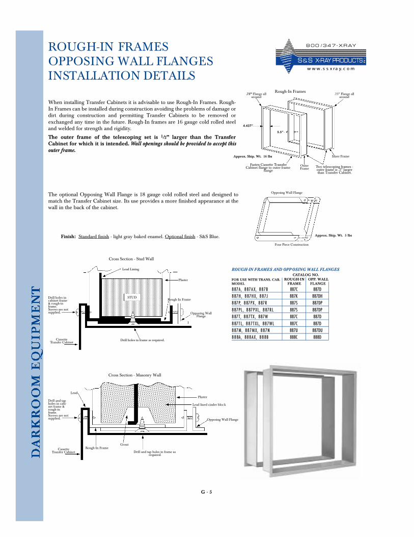
G - 5
ROUGH-IN FRAMESOPPOSING WALL FLANGESINSTALLATION DETAILS
When installing Transfer Cabinets it is advisable to use Rough-In Frames. Rough-In Frames can be installed during construction avoiding the problems of damage ordirt during construction and permitting Transfer Cabinets to be removed orexchanged any time in the future. Rough-In frames are 16 gauge cold rolled steeland welded for strength and rigidity.
The outer frame of the telescoping set is 1/2” larger than the TransferCabinet for which it is intended. Wall openings should be provided to accept thisouter frame.
Finish: Standard finish - light gray baked enamel. Optional finish - S&S Blue.
The optional Opposing Wall Flange is 18 gauge cold rolled steel and designed tomatch the Transfer Cabinet size. Its use provides a more finished appearance at thewall in the back of the cabinet.
OuterFrame
4.437”
5.5”
Rough-In Frames
Fasten Cassette TransferCabinet flange to outer frame
flangeTwo telescoping frames -outer frame is .5” largerthan Transfer Cabinet.
Inner Frame
.75” Flange allaround
.75” Flange allaround
Four Piece Construction
Opposing Wall Flange
ROUGH-IN FRAMES AND OPPOSING WALL FLANGES
8 87A , 887 A X, 887 B 887C 887D8 87H, 887HX, 887 J 887K 887DH8 87 P, 887PX , 887 R 887S 887DP8 87PL , 887PXL, 887 R L 887S 887DP8 87 T, 887 TX , 887 W 887C 887D8 87 T L, 887 T XL, 887 W L 887C 887D8 87M, 887MX, 887 N 887U 887DU888A , 888AX , 888B 888C 888D
FOR USE WITH TRANS. CAB.MODEL
CATALOG NO.
Approx. Ship. Wt. 16 lbs
Approx. Ship. Wt. 5 lbs
ROUGH-INFRAME
OPP. WALLFLANGE
Cross Section - Stud Wall
STUD
Lead Lining
Plaster
Rough-In Frame
Opposing WallFlange
Drill holes in frame as required. CassetteTransfer Cabinet
Drill holes incabinet frame& rough-inframe. Screws are notsupplied.
Drill and tap holes in frame asrequired.
CassetteTransfer Cabinet
Drill and tapholes in cabi-net frame &rough-inframe. Screws are notsupplied.
Plaster
Lead lined cinder block
Opposing Wall Flange
Cross Section - Masonry Wall
Lead
Rough-In FrameGrout
8 0 0 / 3 4 7 - X R AY
S & S X- R AY PR O D UCTSw w w. s s x ra y. c o m
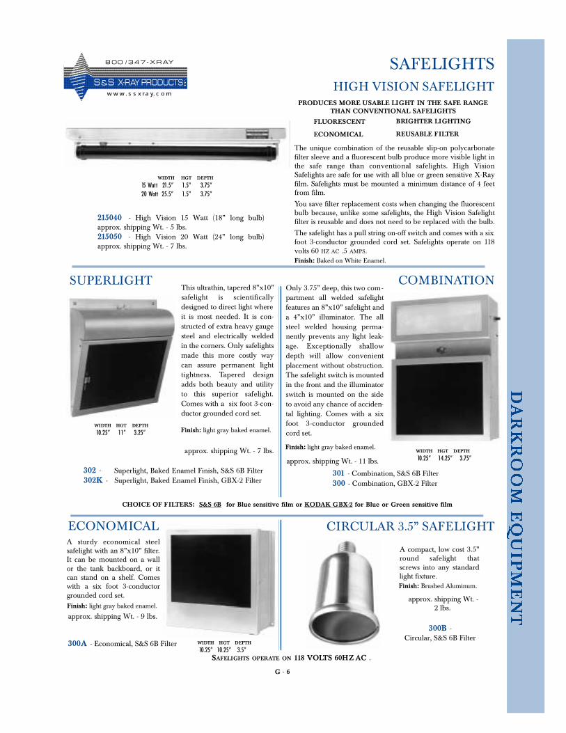
G - 6
SAFELIGHTS
BRIGHTER LIGHTING
REUSABLE FILTER
The unique combination of the reusable slip-on polycarbonatefilter sleeve and a fluorescent bulb produce more visible light inthe safe range than conventional safelights. High Vi s i o nSafelights are safe for use with all blue or green sensitive X-Rayfilm. Safelights must be mounted a minimum distance of 4 feetfrom film.
You save filter replacement costs when changing the fluorescentbulb because, unlike some safelights, the High Vision Safelightfilter is reusable and does not need to be replaced with the bulb.
The safelight has a pull string on-off switch and comes with a sixfoot 3-conductor grounded cord set. Safelights operate on 118volts 60 HZ AC .5 AMPS.
HIGH VISION SAFELIGHT
WIDTH HGT DEPTH
15 Watt 21.5” 1.5” 3.75”20 Watt 25.5” 1.5” 3.75”
FLUORESCENT
ECONOMICAL
PRODUCES MORE USABLE LIGHT IN THE SAFE RANGETHAN CONVENTIONAL SAFELIGHTS
Finish: Baked on White Enamel.
302 - Superlight, Baked Enamel Finish, S&S 6B Filter302K - Superlight, Baked Enamel Finish, GBX-2 Filter
CHOICE OF FILTERS: S&S 6B for Blue sensitive film or KODAK GBX-2 for Blue or Green sensitive film
This ultrathin, tapered 8”x10”safelight is scientificallydesigned to direct light whereit is most needed. It is con-structed of extra heavy gaugesteel and electrically weldedin the corners. Only safelightsmade this more costly waycan assure permanent lighttightness. Tapered designadds both beauty and utilityto this superior safelight.Comes with a six foot 3-con-ductor grounded cord set.
SUPERLIGHT
WIDTH HGT DEPTH
10.25” 11” 3.25”
215040 - High Vision 15 Watt (18” long bulb)approx. shipping Wt. - 5 lbs.215050 - High Vision 20 Watt (24” long bulb)approx. shipping Wt. - 7 lbs.
SAFELIGHTS OPERATE ON 118 VOLTS 60HZ AC .
Finish: light gray baked enamel.
approx. shipping Wt. - 7 lbs.
301 - Combination, S&S 6B Filter300 - Combination, GBX-2 Filter
Only 3.75” deep, this two com-partment all welded safelightfeatures an 8”x10” safelight anda 4”x10” illuminator. The allsteel welded housing perma-nently prevents any light leak-age. Exceptionally shallowdepth will allow convenientplacement without obstruction.The safelight switch is mountedin the front and the illuminatorswitch is mounted on the sideto avoid any chance of acciden-tal lighting. Comes with a sixfoot 3-conductor groundedcord set.
COMBINATION
WIDTH HGT DEPTH
10.25” 14.25” 3.75”
Finish: light gray baked enamel.
approx. shipping Wt. - 11 lbs.
300A - Economical, S&S 6B Filter
A sturdy economical steelsafelight with an 8”x10” filter.It can be mounted on a wallor the tank backboard, or itcan stand on a shelf. Comeswith a six foot 3-conductorgrounded cord set.
ECONOMICAL
WIDTH HGT DEPTH
10.25” 10.25” 3.5”
Finish: light gray baked enamel.
approx. shipping Wt. - 9 lbs.
300B -Circular, S&S 6B Filter
A compact, low cost 3.5”round safelight thatscrews into any standardlight fixture.
CIRCULAR 3.5” SAFELIGHT
Finish: Brushed Aluminum.
approx. shipping Wt. -2 lbs.
8 0 0 / 3 4 7 - X R AY
S &S X- R AY PR O D UCTSw w w . s s x ra y. c o m
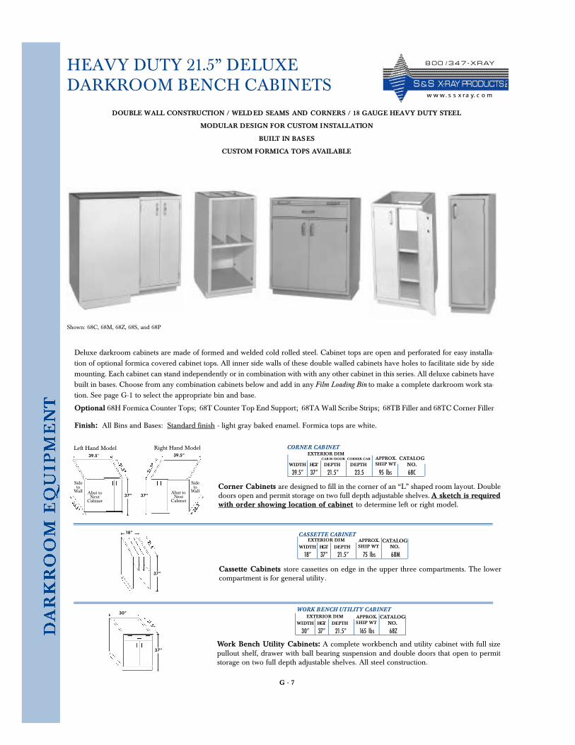
G - 7
HEAVY DUTY 21.5” DELUXEDARKROOM BENCH CABINETS
Deluxe darkroom cabinets are made of formed and welded cold rolled steel. Cabinet tops are open and perforated for easy installa-tion of optional formica covered cabinet tops. All inner side walls of these double walled cabinets have holes to facilitate side by sidemounting. Each cabinet can stand independently or in combination with with any other cabinet in this series. All deluxe cabinets havebuilt in bases. Choose from any combination cabinets below and add in any Film Loading Bin to make a complete darkroom work sta-tion. See page G-1 to select the appropriate bin and base.
Optional 68H Formica Counter Tops; 68T Counter Top End Support; 68TA Wall Scribe Strips; 68TB Filler and 68TC Corner Filler
Finish: All Bins and Bases: Standard finish - light gray baked enamel. Formica tops are white.
CORNER CABINET
39.5” 37” 21.5” 23.5 95 lbs 68CWIDTH HGT DEPTH DEPTH SHIP WT
EXTERIOR DIMAPPROX. CATALOG
NO.
DOUBLE WALL CONSTRUCTION / WELDED SEAMS AND CORNERS / 18 GAUGE HEAVY DUTY STEEL
MODULAR DESIGN FOR CUSTOM INSTALLATION
BUILT IN BASES
CUSTOM FORMICA TOPS AVAILABLE
CAB.W/DOOR CORNER CAB
Shown: 68C, 68M, 68Z, 68S, and 68P
39.5”
37”Abut to
NextCabinet
Sideto
Wall
39.5”
37”Abut to
NextCabinet
Sideto
Wall
Left Hand Model Right Hand Model
Corner Cabinets are designed to fill in the corner of an “L” shaped room layout. Doubledoors open and permit storage on two full depth adjustable shelves. A sketch is requiredwith order showing location of cabinet to determine left or right model.
CASSETTE CABINET
18” 37” 21.5” 75 lbs 68MWIDTH HGT DEPTH SHIP WT
EXTERIOR DIM APPROX. CATALOGNO.
Cassette Cabinets store cassettes on edge in the upper three compartments. The lowercompartment is for general utility.
37”
18”
WORK BENCH UTILITY CABINET
30” 37” 21.5” 165 lbs 68ZWIDTH HGT DEPTH SHIP WT
EXTERIOR DIM APPROX. CATALOGNO.
Work Bench Utility Cabinets: A complete workbench and utility cabinet with full sizepullout shelf, drawer with ball bearing suspension and double doors that open to permitstorage on two full depth adjustable shelves. All steel construction.
37”
30”
8 0 0 / 3 4 7 - X R AY
S & S X- R AY PR O D UCTSw w w. s s x ra y. c o m
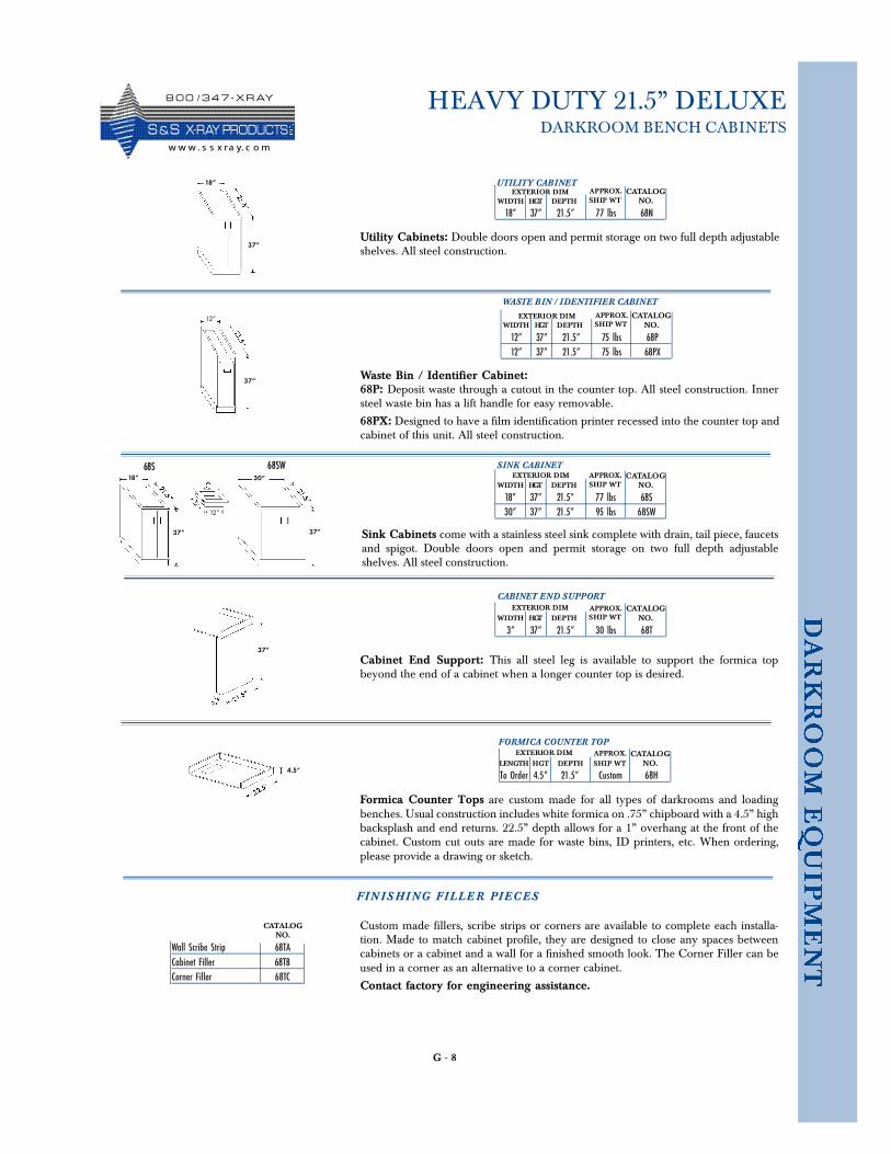
G - 8
HEAVY DUTY 21.5” DELUXEDARKROOM BENCH CABINETS
37”
12”
37”
WASTE BIN / IDENTIFIER CABINET
12” 37” 21.5” 75 lbs 68P12” 37” 21.5” 75 lbs 68PX
WIDTH HGT DEPTH SHIP WTEXTERIOR DIM APPROX. CATALOG
NO.
68P: Deposit waste through a cutout in the counter top. All steel construction. Innersteel waste bin has a lift handle for easy removable.
68PX: Designed to have a film identification printer recessed into the counter top andcabinet of this unit. All steel construction.
SINK CABINET
18” 37” 21.5” 77 lbs 68S30” 37” 21.5” 95 lbs 68SW
WIDTH HGT DEPTH SHIP WTEXTERIOR DIM APPROX. CATALOG
NO.
Sink Cabinets come with a stainless steel sink complete with drain, tail piece, faucetsand spigot. Double doors open and permit storage on two full depth adjustableshelves. All steel construction.
37”37”
30”18”
12”
UTILITY CABINET
18” 37” 21.5” 77 lbs 68NWIDTH HGT DEPTH SHIP WT
EXTERIOR DIM APPROX. CATALOGNO.
Utility Cabinets: Double doors open and permit storage on two full depth adjustableshelves. All steel construction.
37”
18”
FORMICA COUNTER TOP
To Order 4.5” 21.5” Custom 68HL ENGTH HGT DEPTH SHIP WT
EXTERIOR DIM APPROX. CATALOGNO.
Formica Counter Tops are custom made for all types of darkrooms and loadingbenches. Usual construction includes white formica on .75” chipboard with a 4.5” highbacksplash and end returns. 22.5” depth allows for a 1” overhang at the front of thecabinet. Custom cut outs are made for waste bins, ID printers, etc. When ordering,please provide a drawing or sketch.
CABINET END SUPPORT
3” 37” 21.5” 30 lbs 68TWIDTH HGT DEPTH SHIP WT
EXTERIOR DIM APPROX. CATALOGNO.
Cabinet End Support: This all steel leg is available to support the formica topbeyond the end of a cabinet when a longer counter top is desired.
4.5”
FI N I S HI NG FIL L E R PI E C ES
Wall Scribe Strip 68TACabinet Filler 68TBCorner Filler 68TC
CATALOGNO.
Custom made fillers, scribe strips or corners are available to complete each installa-tion. Made to match cabinet profile, they are designed to close any spaces betweencabinets or a cabinet and a wall for a finished smooth look. The Corner Filler can beused in a corner as an alternative to a corner cabinet.
Contact factory for engineering assistance.
68S 68SW
Waste Bin / Identifier Cabinet:
8 0 0 / 3 4 7 - X R AY
S &S X- R AY PR O D UCTSw w w . s s x ra y. c o m
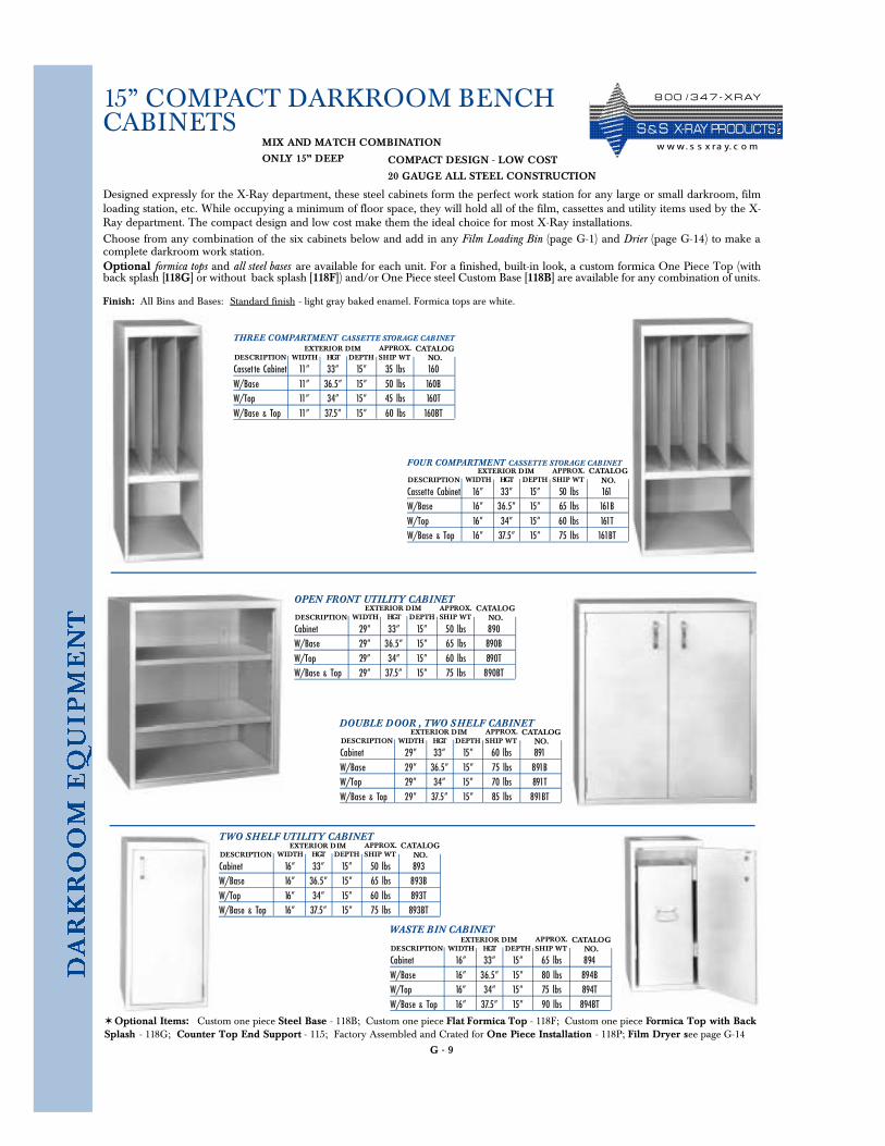
G - 9
15” COMPACT DARKROOM BENCHCABINETS
Designed expressly for the X-Ray department, these steel cabinets form the perfect work station for any large or small darkroom, filmloading station, etc. While occupying a minimum of floor space, they will hold all of the film, cassettes and utility items used by the X-Ray department. The compact design and low cost make them the ideal choice for most X-Ray installations.Choose from any combination of the six cabinets below and add in any Film Loading Bin (page G-1) and Drier (page G-14) to make acomplete darkroom work station.Optional formica tops and all steel bases are available for each unit. For a finished, built-in look, a custom formica One Piece Top (withback splash [118G] or without back splash [118F]) and/or One Piece steel Custom Base [118B] are available for any combination of units.
MIX AND MATCH COMBINATION
ONLY 15” DEEP
Finish: All Bins and Bases: Standard finish - light gray baked enamel. Formica tops are white.
THREE COMPARTMENT CASSETTE STORAGE CABINET
Casset te Cabinet 11” 33” 15” 35 lbs 160W/Base 11” 36.5” 15” 50 lbs 160BW/Top 11” 34” 15” 45 lbs 160TW/Base & Top 11” 37.5” 15” 60 lbs 160BT
DESCRIPTION WIDTH HGT DEPTH SHIP WTEXTERIOR DIM APPROX. CATALOG
NO.
FOUR COMPARTMENT CASSETTE STORAGE CABINET
Cassette Cabinet 16” 33” 15” 50 lbs 161W/Base 16” 36.5” 15” 65 lbs 161BW/Top 16” 34” 15” 60 lbs 161TW/Base & Top 16” 37.5” 15” 75 lbs 161BT
DESCRIPTION WIDTH HGT DEPTH SHIP WTEXTERIOR DIM APPROX. CATALOG
NO.
OPEN FRONT UTILITY CABINET
Cabinet 29” 33” 15” 50 lbs 890W/Base 29” 36.5” 15” 65 lbs 890BW/Top 29” 34” 15” 60 lbs 890TW/Base & Top 29” 37.5” 15” 75 lbs 890BT
DESCRIPTION WIDTH HGT DEPTH SHIP WTEXTERIOR DIM APPROX. CATALOG
NO.
DOUBLE DOOR , TWO SHELF CABINET
Cabinet 29” 33” 15” 60 lbs 891W/Base 29” 36.5” 15” 75 lbs 891BW/Top 29” 34” 15” 70 lbs 891TW/Base & Top 29” 37.5” 15” 85 lbs 891BT
DESCRIPTION WIDTH HGT DEPTH SHIP WTEXTERIOR DIM APPROX. CATALOG
NO.
TWO SHELF UTILITY CABINET
Cabinet 16” 33” 15” 50 lbs 893W/Base 16” 36.5” 15” 65 lbs 893BW/Top 16” 34” 15” 60 lbs 893TW/Base & Top 16” 37.5” 15” 75 lbs 893BT
DESCRIPTION WIDTH HGT DEPTH SHIP WTEXTERIOR DIM APPROX. CATALOG
NO.
WASTE BIN CABINET
Cabinet 16” 33” 15” 65 lbs 894W/Base 16” 36.5” 15” 80 lbs 894BW/Top 16” 34” 15” 75 lbs 894TW/Base & Top 16” 37.5” 15” 90 lbs 894BT
DESCRIPTION WIDTH HGT DEPTH SHIP WTEXTERIOR DIM APPROX. CATALOG
NO.
COMPACT DESIGN - LOW COST
20 GAUGE ALL STEEL CONSTRUCTION
✶ Optional Items: Custom one piece Steel Base - 118B; Custom one piece Flat Formica Top - 118F; Custom one piece Formica Top with BackSplash - 118G; Counter Top End Support - 115; Factory Assembled and Crated for One Piece Installation - 118P; Film Dryer see page G-14
8 0 0 / 3 4 7 - X R AY
S & S X- R AY PR O D UCTSw w w. s s x ra y. c o m

G - 10
DELUXE WALL CABINETS
Ideal for large or small darkrooms, Deluxe WallCabinets provide additional storage space withoutusing valuable floor space. They are the perfect mateto either the 15” Compact Darkroom Be n chCabinets or Heavy Duty 21.5” Deluxe DarkroomBench Cabinets. All inner side walls of these doublewalled cabinets have holes to facilitate side by sidemounting. Choose from any combination of wallcabinets below and add in any Cassette TransferCabinet (page G-3, 4) to make a complete darkroomwork station.
WALL CASSETTE CABINET
3 Compartment 18” 22” 16” 40 lbs 1594 Compartment 24” 22” 16” 51 lbs 158
DESCRIPTION WI DTH HEIGHT DEPTH SHIP WTEXTERIOR DIM APPROX. CATALOG
NO.
Two sizes of Wall Cassette Cabinets are available, 18” wide with three com-partments and 24” wide with four compartments. Both cabinets are all steeldouble wall construction with keyholes provided in the rear for easy hangingand holes in the inner side walls to facilitate bolting units side by side.
WALL UTILITY CABINET
18” 22” 16” 44 lbs 157WIDTH HEIGHT DEPTH SHIP WT
EXTERIOR DIM APPROX. CATALOGNO.
Wall Utility Cabinets are all steel double wall construction with keyholes provid-ed in the rear for easy hanging and holes in the inner side walls to facilitate boltingunits side by side. Double doors, door catch and two adjustable shelves come withthis cabinet.
Finish: Standard finish - light gray baked enamel. Formica topsare white.
DOUBLE WALL WELDED SEAM CONSTRUCTION
ATTRACTIVE WALL MOUNTED UNITS
18 GAUGE HEAVY DUTY STEEL
MODULAR DESIGN FOR CUSTOM INSTALLATION
SAVES FLOOR SPACE
8 0 0 / 3 4 7 - X R AY
S &S X- R AY PR O D UCTSw w w . s s x ra y. c o m
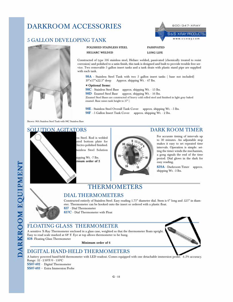
G - 11
DARKROOM ACCESSORIES
5 GALLON DEVELOPING TANK
Constructed of type 316 stainless steel, Heliarc welded, passivated (chemically treated to resistcorrosion) and polished to a satin finish, this tank is designed and built to provide trouble free ser-vice. Two removable 5 gallon insert tanks and a tank drain with plastic stand pipe are suppliedwith each tank.
✶ Optional Items: 98C - Stainless Steel Base approx. shipping Wt. - 15 lbs. 98D - Enamel Steel Base approx. shipping Wt. - 16 lbs. (Enamel Steel Bases are constructed of heavy cold rolled steel and finished in light gray bakedenamel. Base raises tank height to 37”.)
98E - Stainless Steel Overall Tank Cover approx. shipping Wt. - 5 lbs.98F - 5 Gallon Insert Tank Cover approx. shipping Wt. - 2 lbs.
POLISHED STAINLESS STEEL
HELIARC WELDED
PASSIVATED
LONG LIFE
98A - Stainless Steel Tank with two 5 gallon insert tanks ( base not included)19”x17”x22.5” deep Approx. shipping Wt. - 47 lbs.
All Stainless Steel. Rod is weldedto perforated bottom plate forhanging. Electro-polished finished.
175 - Stainless Steel So l u t i o nAgitators approx. shipping Wt. -7 lbs.
Minimum order of 2
DIAL THERMOMETERSConstructed entirely of Stainless Steel. Easy reading 1.75” diameter dial. Stem is 6” long and .125” in diam-eter. Thermometer can be hooked onto the insert or ordered with a plastic float.837 - Dial Thermometer837C - Dial Thermometer with Float
THERMOMETERS
DARK ROOM TIMERFor accurate timing of intervals upto 30 minutes. An adjustable stopmakes it easy to set repeated timeintervals. Operation is simple: set-ting the timer winds the mechanism,a gong signals the end of the timeperiod. Dial glows in the dark foreasy reading.
839A - Darkroom Timer approx.shipping Wt. -3 lbs.
DIGITAL HAND-HELD THERMOMETERSA battery powered hand-held thermometer with LED readout. Comes equipped with one detachable immersion probe. ±.5% accuracy.Range: 32 - 2300F/0 - 1100CSS07-402 - Digital Thermometer SS07-403 - Extra Immersion Probe
Shown: 98A Stainless Steel Tank with 98C Stainless Base
SOLUTION AGITATORS
FLOATING GLASS THERMOMETERA sensitive X-Ray Thermometer enclosed in a glass case, weighted so that the thermometer floats upright.Easy to read scale marked at 680 F. Eye at top allows thermometer to be hung.838- Floating Glass Thermometer
Minimum order of 6
8 0 0 / 3 4 7 - X R AY
S & S X- R AY PR O D UCTSw w w. s s x ra y. c o m
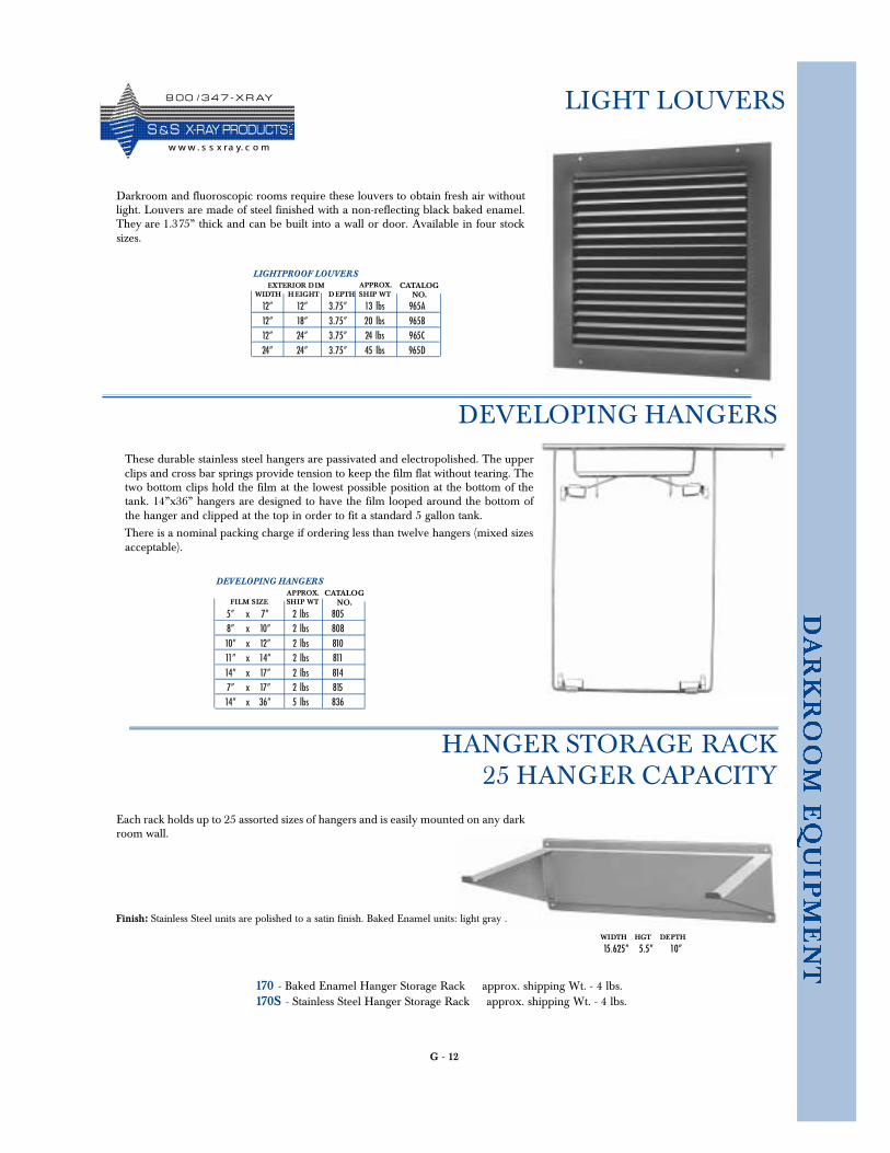
G - 12
LIGHT LOUVERS
LIGHTPROOF LOUVERS
12” 12” 3.75” 13 lbs 965A12” 18” 3.75” 20 lbs 965B12” 24” 3.75” 24 lbs 965C24” 24” 3.75” 45 lbs 965D
WIDTH H EIGHT D EPTH SHIP WTEXTERIOR DIM APPROX. CATALOG
NO.
Darkroom and fluoroscopic rooms require these louvers to obtain fresh air withoutlight. Louvers are made of steel finished with a non-reflecting black baked enamel.They are 1.375” thick and can be built into a wall or door. Available in four stocksizes.
170 - Baked Enamel Hanger Storage Rack approx. shipping Wt. - 4 lbs. 170S - Stainless Steel Hanger Storage Rack approx. shipping Wt. - 4 lbs.
DEVELOPING HANGERS
HANGER STORAGE RACK25 HANGER CAPACITY
DEVELOPING HANGERS
5” x 7” 2 lbs 8058” x 10” 2 lbs 80810” x 12” 2 lbs 81011” x 14” 2 lbs 81114” x 17” 2 lbs 8147” x 17” 2 lbs 81514” x 36” 5 lbs 836
FILM SIZE SHIP WTAPPROX. CATALOG
NO.
These durable stainless steel hangers are passivated and electropolished. The upperclips and cross bar springs provide tension to keep the film flat without tearing. Thetwo bottom clips hold the film at the lowest possible position at the bottom of thetank. 14”x36” hangers are designed to have the film looped around the bottom ofthe hanger and clipped at the top in order to fit a standard 5 gallon tank.
There is a nominal packing charge if ordering less than twelve hangers (mixed sizesacceptable).
Each rack holds up to 25 assorted sizes of hangers and is easily mounted on any darkroom wall.
WIDTH HGT DEPTH
15.625” 5.5” 10”
Finish: Stainless Steel units are polished to a satin finish. Baked Enamel units: light gray .
8 0 0 / 3 4 7 - X R AY
S &S X- R AY PR O D UCTSw w w . s s x ra y. c o m
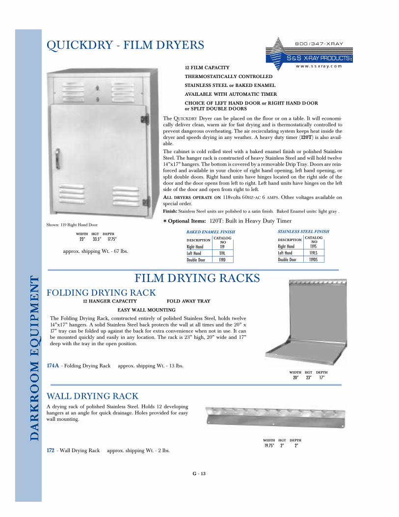
G - 13
QUICKDRY - FILM DRYERS
BAKED ENAMEL FINISH
Right Hand 119Left Hand 119LDouble Door 119D
DESCRIPTIONCATALOG
NO
✶ Optional Items: 120T: Built in Heavy Duty Timer
12 FILM CAPACITY
THERMOSTATICALLY CONTROLLED
STAINLESS STEEL or BAKED ENAMEL
AVAILABLE WITH AUTOMATIC TIMER
CHOICE OF LEFT HAND DOOR or RIGHT HAND DOORor SPLIT DOUBLE DOORS
Finish: Stainless Steel units are polished to a satin finish. Baked Enamel units: light gray .
The QUICKDRY Dryer can be placed on the floor or on a table. It will economi-cally deliver clean, warm air for fast drying and is thermostatically controlled toprevent dangerous overheating. The air recirculating system keeps heat inside thedryer and speeds drying in any weather. A heavy duty timer (120T) is also avail-able.
The cabinet is cold rolled steel with a baked enamel finish or polished StainlessSteel. The hanger rack is constructed of heavy Stainless Steel and will hold twelve14”x17” hangers. The bottom is covered by a removable Drip Tray. Doors are rein-forced and available in your choice of right hand opening, left hand opening, orsplit double doors. Right hand units have hinges located on the right side of thedoor and the door opens from left to right. Left hand units have hinges on the leftside of the door and open from right to left.
ALL DRYERS OPERATE ON 118volts 60HZ-AC 6 AMPS. Other voltages available onspecial order.
12 HANGER CAPACITY FOLD AWAY TRAY
EASY WALL MOUNTING
The Folding Drying Rack, constructed entirely of polished Stainless Steel, holds twelve14”x17” hangers. A solid Stainless Steel back protects the wall at all times and the 20” x17” tray can be folded up against the back for extra convenience when not in use. It canbe mounted quickly and easily in any location. The rack is 23” high, 20” wide and 17”deep with the tray in the open position.
FILM DRYING RACKS
174A - Folding Drying Rack approx. shipping Wt. - 13 lbs.
FOLDING DRYING RACK
WIDTH HGT DEPTH
19.75” 2” 2”
A drying rack of polished Stainless Steel. Holds 12 developinghangers at an angle for quick drainage. Holes provided for easywall mounting.
172 - Wall Drying Rack approx. shipping Wt. - 2 lbs.
WALL DRYING RACK
approx. shipping Wt. - 67 lbs.
WIDTH HGT DEPTH
23” 33.5” 17.75”
STAINLESS STEEL FINISH
Right Hand 119SLeft Hand 119LSDouble Door 119DS
DESCRIPTIONCATALOG
NO
Shown: 119 Right Hand Door
WIDTH HGT DEPTH
20” 23” 17”
8 0 0 / 3 4 7 - X R AY
S & S X- R AY PR O D UCTSw w w. s s x ra y. c o m
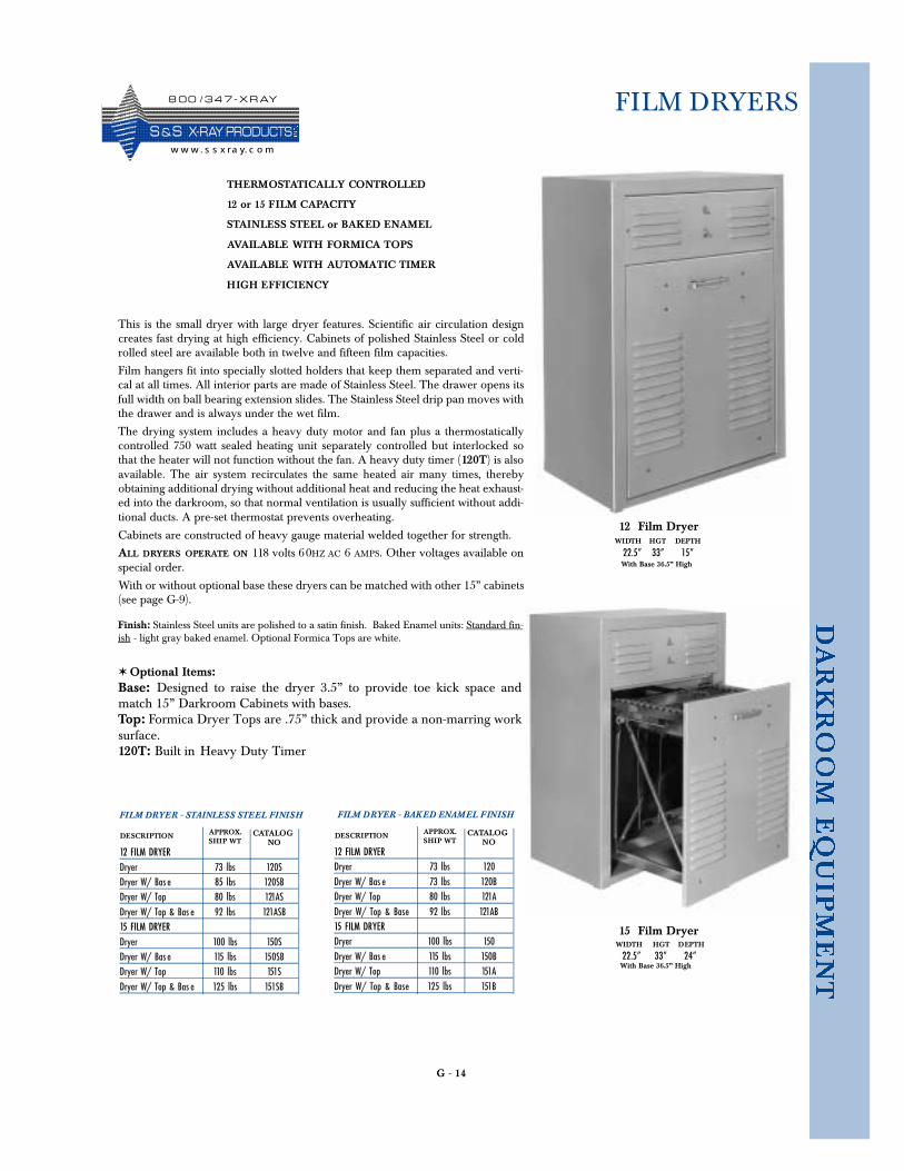
G - 14
FILM DRYERS
This is the small dryer with large dryer features. Scientific air circulation designcreates fast drying at high efficiency. Cabinets of polished Stainless Steel or coldrolled steel are available both in twelve and fifteen film capacities.
Film hangers fit into specially slotted holders that keep them separated and verti-cal at all times. All interior parts are made of Stainless Steel. The drawer opens itsfull width on ball bearing extension slides. The Stainless Steel drip pan moves withthe drawer and is always under the wet film.
The drying system includes a heavy duty motor and fan plus a thermostaticallycontrolled 750 watt sealed heating unit separately controlled but interlocked sothat the heater will not function without the fan. A heavy duty timer (120T) is alsoavailable. The air system recirculates the same heated air many times, therebyobtaining additional drying without additional heat and reducing the heat exhaust-ed into the darkroom, so that normal ventilation is usually sufficient without addi-tional ducts. A pre-set thermostat prevents overheating.
Cabinets are constructed of heavy gauge material welded together for strength.
ALL DRYERS OPERATE ON 118 volts 60HZ AC 6 AMPS. Other voltages available onspecial order.
With or without optional base these dryers can be matched with other 15” cabinets(see page G-9).
✶ Optional Items: Base: Designed to raise the dryer 3.5” to provide toe kick space andmatch 15” Darkroom Cabinets with bases.Top: Formica Dryer Tops are .75” thick and provide a non-marring worksurface.120T: Built in Heavy Duty Timer
WIDTH HGT DEPTH
With Base 36.5” High 22.5” 33” 15”
THERMOSTATICALLY CONTROLLED
12 or 15 FILM CAPACITY
STAINLESS STEEL or BAKED ENAMEL
AVAILABLE WITH FORMICA TOPS
AVAILABLE WITH AUTOMATIC TIMER
HIGH EFFICIENCY
Finish: Stainless Steel units are polished to a satin finish. Baked Enamel units: Standard fin-ish - light gray baked enamel. Optional Formica Tops are white.
12 Film Dryer
WIDTH HGT DEPTH
22.5” 33” 24”
15 Film Dryer
FILM DRYER - BAKED ENAMEL FINISH
12 FILM DRYERDryer 73 lbs 120Dryer W/ Bas e 73 lbs 120BDryer W/ Top 80 lbs 121ADryer W/ Top & Base 92 lbs 121AB15 FILM DRYERDryer 100 lbs 150Dryer W/ Bas e 115 lbs 150BDryer W/ Top 110 lbs 151ADryer W/ Top & Base 125 lbs 151B
DESCRIPTION CATALOGNOSHIP WT
APPROX.
FILM DRYER - STAINLESS STEEL FINISH
12 FILM DRYERDryer 73 lbs 120SDryer W/ Bas e 85 lbs 120SBDryer W/ Top 80 lbs 121ASDryer W/ Top & Bas e 92 lbs 121ASB15 FILM DRYERDryer 100 lbs 150SDryer W/ Bas e 115 lbs 150SBDryer W/ Top 110 lbs 151SDryer W/ Top & Bas e 125 lbs 151SB
DESCRIPTION CATALOGNOSHIP WT
APPROX.
With Base 36.5” High
8 0 0 / 3 4 7 - X R AY
S &S X- R AY PR O D UCTSw w w . s s x ra y. c o m