sr 520 bridge replacement and hov project deis - … 520 bridge replacement and hov project draft...
TRANSCRIPT

SR 520 Bridge Replacementand HOV Project Draft EIS
1 March 2005
Appendix A
Description ofAlternatives and
Construction Techniques
8 5/8
” trim
line
9“ tr
imlin
e

SR 520 Bridge Replacement and HOV Project Draft EIS
Description of Alternatives and Construction Techniques
Report
Prepared for
Washington State Department of Transportation Federal Highway Administration
Sound Transit
Lead Author
CH2M HILL
Consultant Team
Parametrix, Inc. CH2M HILL
Parsons Brinckerhoff Michael Minor and Associates
March 1, 2005


SR 520 Bridge Replacement and HOV Project | Description of Alternatives and Construction Techniques Report
DESCRIPTION_ALTERNATIVES_030105.DOC iii
Contents List of Exhibits ..............................................................................................................................v Acronyms and Abbreviations ................................................................................................viii
Description of Alternatives Alternatives Considered .............................................................................................................1
How did we choose alternatives to evaluate? ..............................................................1 What was first-level screening?......................................................................................1 What was second-level screening?.................................................................................2 What happened to the 8-Lane Alternative?..................................................................4
EIS Alternatives Description......................................................................................................5
What is the No Build Alternative? ............................................................................................5
What is the 4-Lane Alternative?.................................................................................................7 Seattle .................................................................................................................................7 Lake Washington............................................................................................................10 Eastside ............................................................................................................................12
What is the 6-Lane Alternative?...............................................................................................14 Seattle ...............................................................................................................................14 Lake Washington............................................................................................................18 Eastside ............................................................................................................................20
What features are similar in the 4-Lane and 6-Lane Alternatives? ...................................22 Bicycle/Pedestrian Path ................................................................................................22 Stormwater Treatment...................................................................................................23 Navigation Channels .....................................................................................................28 Bridge Operations Facility ............................................................................................28 Pontoon Anchors ............................................................................................................29 Lighting............................................................................................................................30 Aurora Borealis Sculptures ...........................................................................................30 Tolls ..................................................................................................................................30 Flexible Transportation Plan.........................................................................................31
Construction Techniques What types of construction techniques would be used?.....................................................45
Roadway Reconstruction ..............................................................................................45 Retaining Walls...............................................................................................................46
SR 520 Bridge Replacement and HOV Project | Description of Alternatives and Construction Techniques Report
DESCRIPTION_ALTERNATIVES_030105.DOC iv
Sound Walls ....................................................................................................................47 Local Street Crossings....................................................................................................47 Lids ...................................................................................................................................49 Bridge Foundations........................................................................................................49 Temporary Work and Detour Bridges ........................................................................50 Permanent Bridges .........................................................................................................52
What types of construction equipment would be used?.....................................................54
Where are the construction staging areas?.............................................................................55
How long would it take to construct the project? ................................................................56
What is the construction sequence of the 4-Lane and 6-Lane Alternatives?................................................................................................................................57
Bridges over SR 520........................................................................................................58 I-5/SR 520 Interchange ..................................................................................................58 Portage Bay Bridge.........................................................................................................60 Montlake Interchange....................................................................................................61 West Approach to Evergreen Point Bridge.................................................................62 Floating Section of Evergreen Point Bridge................................................................62 East Highrise of Evergreen Point Bridge ....................................................................63 Evergreen Point Road ....................................................................................................63 84th Avenue Northeast and 92nd Avenue Northeast ...............................................64 Bellevue Way ..................................................................................................................65 Auxiliary Lane between I-405 and 124th Avenue Northeast ...................................66
References....................................................................................................................................67 Attachment
1 Scale Drawings of Bridge Profiles

SR 520 Bridge Replacement and HOV Project | Description of Alternatives and Construction Techniques Report
DESCRIPTION_ALTERNATIVES_030105.DOC v
List of Exhibits
Note: To look at one of the exhibits for this Discipline Report, go to the folder entitled "Graphics."
1 Alternatives Screening Process
2 Points Along SR 520 Vulnerable to Earthquakes
3 4-Lane Alternative Footprint
3a 4-Lane Alternative Footprint (I-5/SR 520 Interchange and Portage Bay)
3b 4-Lane Alternative Footprint (Montlake Interchange and Lake Washington Boulevard Ramps)
3c 4-Lane Alternative Footprint (West Approach to Evergreen Point Bridge)
3d 4-Lane Alternative Footprint (East Approach of Evergreen Point Bridge and Evergreen Point Road Interchange)
3e 4-Lane Alternative Footprint (Interchanges at 84th and 92nd Avenues Northeast)
3f 4-Lane Alternative Footprint (Bellevue Way Interchange and Eastern Boundary of Project)
4 4-Lane Alternative Lane Configuration (I-5/SR 520 Interchange)
5 Profile of New Portage Bay Bridge and West Approach to Evergreen Point Bridge
6 Example of Haunched Girder—Bridge Profile View
7 4-Lane Alternative Lane Configuration (Montlake Interchange and Lake Washington Boulevard Ramps)
8 4-Lane Alternative Sound Wall Locations and Heights in Seattle
9 Proposed Pontoon and Anchor Locations
10 Profile of New East Highrise of Evergreen Point Bridge
11 4-Lane Alternative Lane Configuration (Evergreen Point Road/SR 520)
12 4-Lane Alternative Lane Configuration (84th Avenue Northeast/SR 520 Interchange)
13 4-Lane Alternative Lane Configuration (92nd Avenue Northeast/SR 520 Interchange)
SR 520 Bridge Replacement and HOV Project | Description of Alternatives and Construction Techniques Report
DESCRIPTION_ALTERNATIVES_030105.DOC vi
14 4-Lane Alternative Lane Configuration (Bellevue Way/SR 520 Interchange)
15 4-Lane Alternative Sound Wall Locations and Heights on the Eastside
16 6-Lane Alternative Footprint
16a 6-Lane Alternative Footprint (I-5/SR 520 Interchange and Portage Bay)
16b 6-Lane Alternative Footprint (Montlake Interchange and Lake Washington Boulevard Ramps)
16c 6-Lane Alternative Footprint (West Approach to Evergreen Point Bridge)
16d 6-Lane Alternative Footprint (East Approach of Evergreen Point Bridge and Evergreen Point Road Interchange)
16e 6-Lane Alternative Footprint (Interchanges at 84th and 92nd Avenues Northeast)
16f 6-Lane Alternative Footprint (Bellevue Way Interchange and Eastern Boundary of Project)
17 6-Lane Alternative Lane Configuration (I-5/SR 520 Interchange)
18 6-Lane Alternative Lane Configuration (Montlake Interchange and Lake Washington Boulevard Ramps)
19 Community Ideas for the Design of the 10th and Delmar and Montlake Lids
20 6-Lane Alternative Sound Wall Locations and Heights in Seattle
21 6-Lane Alternative Lane Configuration (Evergreen Point Road/SR 520 Interchange)
22 6-Lane Alternative Lane Configuration (84th Avenue Northeast/SR 520 Interchange)
23 6-Lane Alternative Lane Configuration (92nd Avenue Northeast/SR 520 Interchange)
24 6-Lane Alternative Lane Configuration (Bellevue Way/SR 520 Interchange)
25 Community Ideas for the Design of the Evergreen Point, 84th Avenue Northeast, and 92nd Avenue Northeast Lids
26 6-Lane Alternative Sound Wall Locations and Heights on the Eastside
27 Existing and Proposed Trails in Seattle

SR 520 Bridge Replacement and HOV Project | Description of Alternatives and Construction Techniques Report
DESCRIPTION_ALTERNATIVES_030105.DOC vii
28 Proposed Stormwater Management Facilities
29 Example of a Stormwater Treatment Wetland
30 Stormwater Treatment Wetland at Bridge Column
31 Schematic Representation of Stormwater Mixing Processes for Floating Bridge
32 Schematic Section View of Proposed Mixing Zone Boundaries for Bridge Alternatives
33 Schematic Plan View of Stormwater System Configurations and Mixing Zone Boundaries for Bridge Alternatives
34 Existing, 4-Lane, and 6-Lane Alternative Navigational Restrictions for the Evergreen Point Bridge
35 Conceptual Sketch of the Structure of the Bridge Operations Facility
36 Conceptual Sketches of Likely Floating Bridge Anchor Installation and Operation
37 Proposed Toll Rates for Evergreen Point Bridge for 2030
38 Construction Period TDM Plan Elements
39 Construction Period ITS Elements
40 20-Year Flexible Transportation Plan
41 Typical Concrete Wall in a Cut Slope
42 Typical Soil Nail Wall in a Cut Slope
43 Typical Soldier Pile Wall in a Cut Slope
44 4-Lane Alternative Temporary Work Bridges in Portage Bay
45 6-Lane Alternative Temporary Work Bridges in Portage Bay
46 4-Lane Temporary Detour Bridges in Union Bay and at the Arboretum
47 6-Lane Temporary Detour Bridges in Union Bay and at the Arboretum
48 Typical Equipment and Use for Roadway Construction
49 Construction Duration of the 4-Lane and 6-Lane Alternatives
50 Construction Sequence of the 4-Lane and 6-Lane Alternatives


SR 520 Bridge Replacement and HOV Project | Description of Alternatives and Construction Techniques Report
DESCRIPTION_ALTERNATIVES_030105.DOC viii
Acronyms and Abbreviations ATM automatic teller machine
BMP best management practice
EIS Environmental Impact Statement
ETC electronic toll collection
FTP Flexible Transportation Plan
HCT high-capacity transit
HOV high-occupancy vehicle
ITS Intelligent Transportation System
MOHAI Museum of History and Industry
MOT maintenance of traffic
NEPA National Environmental Policy Act
NOAA National Oceanic and Atmospheric Administration
SEPA State Environmental Policy Act
SOV single-occupancy vehicle
TDM transportation demand management
TSMC Transportation System Management Center
VMS variable message sign
WSDOT Washington State Department of Transportation

SR 520 Bridge Replacement and HOV Project | Description of Alternatives and Construction Techniques Report
DESCRIPTION_ALTERNATIVES_030105.DOC 1
Description of Alternatives This section describes how the SR 520 Bridge Replacement and HOV Project alternatives were developed and considered for analysis, and what is included in the Environmental Impact Statement (EIS) alternatives. These descriptions provide more detail than the Draft EIS and the associated discipline reports. Effects of the alternatives are not included.
Alternatives Considered
How did we choose alternatives to evaluate? The project team identified many preliminary alternatives during the public scoping process. We studied all of the suggested alternatives through a first-level and a two-part, second-level screening process (as described in the technical memorandum Alternatives Analysis-Screening Process and Criteria Adopted by Executive Committee on October 25, 2000 (November 6, 2000)). The completion of the second-level screening analysis resulted in the definition of the alternatives carried forward into this EIS. The alternatives screening process is summarized in Exhibit 1. The various reports documenting the alternatives screening process are cited in the discussion below and are incorporated into this EIS by reference.
What was first-level screening? The project team used the first-level screening analysis to eliminate alternatives that did not meet the purpose and need statement for the Trans-Lake Washington Project,1 or those that did not score as high as the alternatives recommended by the Trans-Lake Washington Study Committee. We asked the following three questions for each alternative during first-level screening.
• Will the alternative be effective in improving mobility for people and goods?
1 Now called the SR 520 Bridge Replacement and HOV Project
SR 520 Bridge Replacement and HOV Project | Description of Alternatives and Construction Techniques Report
DESCRIPTION_ALTERNATIVES_030105.DOC 2
The criteria used to answer this question were (1) how much the alternative improved mobility, (2) whether the alternative increased or decreased reliability and safety, and (3) whether the alternative was compatible with other existing transportation system plans.
• Can we reasonably avoid, minimize, or mitigate its environmental impacts?
The resources evaluated to answer this question were wetlands; habitat for species listed under the Endangered Species Act; Section 4(f) and Section 106 properties; residential and commercial displacements; and neighborhood disruption and community cohesion.
• How much will it cost?
A “ballpark” cost estimate was made for each major concept.
The first-level screening analysis in October 2000 included 19 alternatives. These alternatives were categorized into four different solution categories or themes:
• Highway solutions • Transit solutions • Transportation demand management (TDM) solutions • Other solutions (such as ferries or arterials)
We evaluated each alternative against the other alternatives within its theme according to the basic transportation, environmental, and cost criteria described above. Results of the first-level screening process are summarized in First-Level Screening Results-Technical Steering Committee Review Draft with Comments (WSDOT and Sound Transit October 2000). Exhibit 1 shows the alternatives considered in first-level screening and those that were passed on to second-level screening.
What was second-level screening? The project team used the second-level screening process to determine which multimodal alternatives would be considered in the EIS. The second-level screening analysis consisted of several steps. First, we conducted a modal analysis that separately compared highway and high-capacity transit (HCT) alternatives within their mode of operation. Next, the best modal alternatives were combined to create seven multimodal alternatives, each with highway and HCT components. Finally, the Trans-Lake
Modal screening means that alternatives using only one mode or type of transportation (i.e., only highway alternatives) are compared.
Multimodal screening means that alternatives using a combination of transportation modes or types are compared (i.e., each alternative has a combination of highway and transit improvements).

SR 520 Bridge Replacement and HOV Project | Description of Alternatives and Construction Techniques Report
DESCRIPTION_ALTERNATIVES_030105.DOC 3
Washington Project Executive Committee recommended alternatives to be evaluated in the EIS.
The second-level screening analysis considered more factors at a higher level of analysis. The three main criteria for screening the modal and multimodal components of this project were effectiveness, environmental impacts, and cost, just as in the first-level screening.
To determine the effectiveness of the alternatives, the project team considered the following factors:
• Mobility • Reliability and safety • System compatibility
To determine the environmental impacts of the alternatives, the project team considered:
• Displacement/disruption • Neighborhood, Section 4(f) and Section 106 resources • Noise and vibration • Visual quality • Land use • Fish-bearing streams/threatened and endangered species • Critical upland habitat/threatened and endangered species • Wetlands, shorelines, and habitat connectivity • Water resources (quantity and quality) • Air quality
To evaluate the costs of the alternatives, the team considered the following factors:
• Capital costs • Operations and maintenance costs • Life-cycle costs
The results of the modal screening analysis are documented in Highway Modal Evaluation-Transportation, Environmental, and Cost Findings (WSDOT and Sound Transit 2001a) and High Capacity Transit Modal Evaluation—Transportation, Environmental, and Cost Findings (WSDOT and Sound Transit 2001b).
The results of the multimodal screening analysis are documented in Multi-Modal Alternatives Evaluation Report (WSDOT and Sound Transit 2001c). Exhibit 1 shows the modal and multimodal alternatives that
SR 520 Bridge Replacement and HOV Project | Description of Alternatives and Construction Techniques Report
DESCRIPTION_ALTERNATIVES_030105.DOC 4
were considered and the alternatives that were recommended for study in this EIS.
In addition to the two-step second-level screening process described above, a study was done to evaluate how future HCT could be accommodated within the SR 520 corridor (Accommodating High Capacity Transit in the SR 520 Corridor, WSDOT and Sound Transit 2002a).
A summary of the screening process to identify where HCT should be sited across Lake Washington is described in Summary of HCT Screening Process-Evaluation and Recommendations (WSDOT and Sound Transit 2002b).
What happened to the 8-Lane Alternative? In July 1999, the Trans-Lake Study Committee recommended an array of alternatives to be carried forward into a formal National Environmental Policy Act/State Environmental Policy Act (NEPA/SEPA) review process. The 8-Lane Alternative was among these alternatives. During the summer of 2002, the Trans-Lake Washington Project Executive Committee adopted the 6-Lane Alternative as a Preliminary Preferred Alternative and agreed that further analysis of the 8-Lane Alternative would not be required.
Funding for the Trans-Lake Washington project ran out in November 2002, when a ballot measure to fund transportation failed. In 2003, the Washington state legislature passed a nickel gas tax, which restored funding for the project. Along with the funding, the legislature asked the Washington State Department of Transportation (WSDOT) to evaluate the I-5 corridor to determine what modifications would be required on I-5 to alleviate congestion caused by an 8-Lane Alternative. At the same time, the project was renamed the SR 520 Bridge Replacement and HOV Project, the project limits were redefined, and tolling was assumed for the project.
The project team’s 2002 planning-level analyses (with no toll on SR 520) indicated that the I-5 corridor would require one additional lane in each direction between the SR 520 and Corson/Michigan interchanges. With the assumption of a toll on the Evergreen Point Bridge, the team’s second assessment also showed that one additional lane in each direction would be needed on the I-5 corridor from SR 520 south to I-90.
SR 520 Bridge Replacement and HOV Project | Description of Alternatives and Construction Techniques Report
DESCRIPTION_ALTERNATIVES_030105.DOC 5
The project team then developed options for adding capacity along the I-5 corridor. They ultimately combined the various options into three distinct options for evaluation: a tunnel option, an aerial option, and a frontage road option. The project team used a screening process to select one option, which was then carried into the next level of analysis (SR 520 8-Lane Alternative I-5 Options Report, Parametrix and CH2M HILL 2004). The frontage road option was selected because it provided the most reliable improvements with the lowest anticipated cost.
The 8-Lane Alternative was dropped from further evaluation because it would cause severe congestion along I-5 despite the proposed I-5 improvements and would have required additional study on I-5. See Appendix U, 8-Lane Alternative Report, for results of the transportation analysis for the 8-Lane Alternative.
EIS Alternatives Description The SR 520 Bridge Replacement and HOV Project Draft EIS evaluates the following three alternatives and one option:
• No Build Alternative − Continued Operation Scenario − Catastrophic Failure Scenario
• 4-Lane Alternative − Option with pontoons without capacity to carry future HCT
• 6-Lane Alternative
Each of these alternatives is described in detail below.
What is the No Build Alternative? All EISs provide an alternative to assess what would happen to the environment in the future if nothing were done to solve the project’s identified problem. This alternative, sometimes called the No Action or No Build Alternative, means that the existing highway would remain the same as it is today. The No Build Alternative provides the basis for measuring and comparing the effects of all of the project’s build alternatives.
This project is unique because the existing SR 520 bridges may not remain intact through 2030, the project’s design year. The fixed and floating spans of the Portage Bay and Evergreen Point bridges are aging and vulnerable to windstorms and earthquakes.
The design year for this EIS is 2030, which means that the traffic demand used for the alternatives analysis is based on the future 2030 traffic volumes. Typically, environmental documents will use a design year that is 20 to 30 years in the future to capture the future effects of the alternatives while still using a reasonable planning horizon.
SR 520 Bridge Replacement and HOV Project | Description of Alternatives and Construction Techniques Report
DESCRIPTION_ALTERNATIVES_030105.DOC 6
In 1999, WSDOT estimated the remaining service life of the floating bridge to be 20 to 25 years, based on the existing structural integrity and the likelihood of severe windstorms. The floating portion of the Evergreen Point Bridge was originally designed for a sustained wind speed of 57.5 miles per hour (mph). In 1999, the bridge was rehabilitated to allow it to withstand sustained winds up to 77 mph. WSDOT’s current design standards require a bridge to withstand sustained wind speeds of 92 mph. The floating pontoons currently float about 1 foot lower than originally designed. To bring the floating bridge up to current design standards, the floating bridge must be completely replaced. Exhibit 2 shows areas of the Evergreen Point Bridge that are vulnerable to earthquakes and wind damage.
The fixed structures of the Portage Bay and Evergreen Point bridges do not meet current seismic design standards because the columns are hollow. Hollow-core columns are difficult and costly to retrofit to current seismic standards. The 10th Avenue East bridge over SR 520 and the ramps at Montlake and Lake Washington Boulevard are also seismically vulnerable.
If nothing is done to replace the Portage Bay and Evergreen Point bridges, both structures could fail and become unusable to the public before 2030. WSDOT cannot predict when or how these structures might fail, so it is difficult to determine the actual consequences of doing nothing. To illustrate what could happen, the project team developed two scenarios that represent the possible extremes of what could happen if the project were not built; these No Build Alternative scenarios are Continued Operation of SR 520 and Catastrophic Failure of SR 520.
Under the Continued Operation Scenario, SR 520 would continue to operate like it does today—a 4-lane highway with nonstandard shoulders and without a bicycle lane. No new facilities would be added and none would be removed, including the R.H. Thompson Expressway Ramps near the Washington Park Arboretum. This scenario assumes that the Portage Bay and Evergreen Point bridges would remain standing and functional through 2030. No catastrophic events (such as earthquakes or high winds) would be severe enough to cause major damage to the bridges. This scenario is the baseline from which the project team compared the other alternatives.
Under the Catastrophic Failure Scenario, both the Portage Bay and Evergreen Point bridges would be lost because of some kind of

SR 520 Bridge Replacement and HOV Project | Description of Alternatives and Construction Techniques Report
DESCRIPTION_ALTERNATIVES_030105.DOC 7
catastrophic event. Although in a catastrophic event one structure might fail while the other remains standing, the Draft EIS assumes the worst-case scenario—that both bridges would fail or would be so seriously damaged that they would be unavailable for use by the public for an unspecified length of time.
What is the 4-Lane Alternative? The 4-Lane Alternative would have four lanes (two 12-foot general purpose lanes in each direction), the same number of lanes as today. SR 520 would be rebuilt from I-5 to Bellevue Way. Bridges over SR 520 would also be rebuilt. Roadway shoulders would meet current standards (4-foot inside shoulder and 10-foot outside shoulder). Sound walls would be built along much of SR 520 in Seattle and on the Eastside.
As described in more detail later in this section, a bicycle/pedestrian path would be constructed along the north side of SR 520 through Montlake, across the Evergreen Point Bridge, and along the south side of SR 520 through the Eastside. The 4-Lane Alternative would also include a new bridge operations facility under SR 520 built into the east approach structure abutment on the east shore of Lake Washington, stormwater treatment, electronic toll collection, and a flexible transportation plan. Exhibits 3a through 3f show the footprint of the entire 4-Lane Alternative.
Seattle
I-5/SR 520 Interchange Under the 4-Lane Alternative, SR 520 would connect to I-5 almost the same as it does today, with a few exceptions, as shown in Exhibit 4. From westbound SR 520, one lane would exit to either East Roanoke Street or I-5 North, as it does today. Two lanes would connect to I-5 South using the existing structure across I-5. A new HOV-only ramp would connect SR 520 westbound to the I-5 southbound express lanes, which would operate during the morning hours only. Modifications to the I-5 express lanes would include construction of the new ramp and reconstruction of the shoulders.
Connecting to SR 520 eastbound would be similar to today. From I-5 southbound, the existing tunnel would remain intact. From I-5 northbound, a wider two-lane on-ramp would connect to SR 520.
SR 520 Bridge Replacement and HOV Project | Description of Alternatives and Construction Techniques Report
DESCRIPTION_ALTERNATIVES_030105.DOC 8
Bridges over SR 520 Four bridges over SR 520 would be rebuilt to provide room to widen SR 520: 10th Avenue East, Delmar Drive East, Montlake Boulevard, and 24th Avenue East. All, except for Montlake Boulevard, would have the same width and lane configuration as the existing structures. The Montlake Boulevard bridge would be slightly wider and reconfigured in locations to improve the interchange’s functioning.
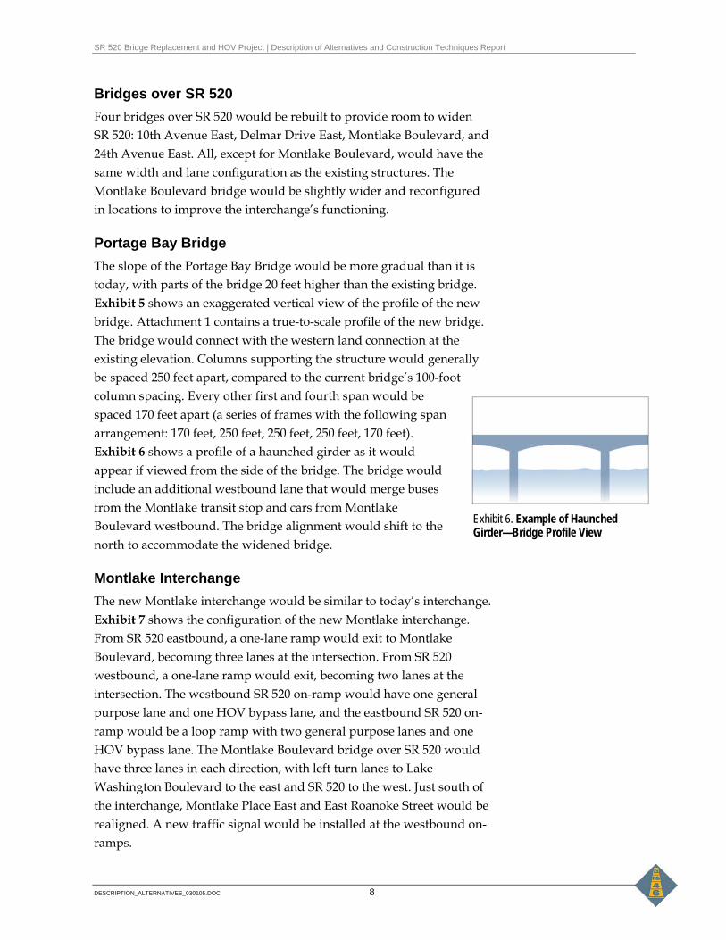
Portage Bay Bridge The slope of the Portage Bay Bridge would be more gradual than it is today, with parts of the bridge 20 feet higher than the existing bridge. Exhibit 5 shows an exaggerated vertical view of the profile of the new bridge. Attachment 1 contains a true-to-scale profile of the new bridge. The bridge would connect with the western land connection at the existing elevation. Columns supporting the structure would generally be spaced 250 feet apart, compared to the current bridge’s 100-foot column spacing. Every other first and fourth span would be spaced 170 feet apart (a series of frames with the following span arrangement: 170 feet, 250 feet, 250 feet, 250 feet, 170 feet). Exhibit 6 shows a profile of a haunched girder as it would appear if viewed from the side of the bridge. The bridge would include an additional westbound lane that would merge buses from the Montlake transit stop and cars from Montlake Boulevard westbound. The bridge alignment would shift to the north to accommodate the widened bridge.
Montlake Interchange The new Montlake interchange would be similar to today’s interchange. Exhibit 7 shows the configuration of the new Montlake interchange. From SR 520 eastbound, a one-lane ramp would exit to Montlake Boulevard, becoming three lanes at the intersection. From SR 520 westbound, a one-lane ramp would exit, becoming two lanes at the intersection. The westbound SR 520 on-ramp would have one general purpose lane and one HOV bypass lane, and the eastbound SR 520 on-ramp would be a loop ramp with two general purpose lanes and one HOV bypass lane. The Montlake Boulevard bridge over SR 520 would have three lanes in each direction, with left turn lanes to Lake Washington Boulevard to the east and SR 520 to the west. Just south of the interchange, Montlake Place East and East Roanoke Street would be realigned. A new traffic signal would be installed at the westbound on-ramps.
Exhibit 6. Example of Haunched Girder—Bridge Profile View
SR 520 Bridge Replacement and HOV Project | Description of Alternatives and Construction Techniques Report
DESCRIPTION_ALTERNATIVES_030105.DOC 9
The Montlake transit stops on SR 520 would be under the Montlake Boulevard bridge over SR 520 in both the eastbound and westbound directions. They would be on the outside of the highway, similar to today.
Lake Washington Boulevard Ramps The existing Lake Washington Boulevard ramps and the existing ramps from the never completed R.H. Thompson Expressway would be removed. Exhibit 7 shows the configuration of the new Lake Washington Boulevard Ramps. The SR 520 westbound Lake Washington off-ramp would cross to the south 20 feet above SR 520, over the WSDOT-owned peninsula west of the Arboretum instead of over Union Bay as the existing ramps do. The SR 520 eastbound on-ramp would be adjacent to the SR 520 westbound off-ramp on the peninsula. The ramps would intersect with Lake Washington Boulevard East in the same place that they do today.
The SR 520 westbound off-ramp would be approximately 65 feet above the water level, when measured from the bottom of the structure, when crossing SR 520.
The SR 520 mainline would shift north of the existing mainline beginning at the Lake Washington Boulevard ramps and continuing through to the Evergreen Point Bridge.
Would there be lids in Seattle? The 4-Lane Alternative would not have lids. The Executive Committee agreed that because the 4-Lane Alternative would only replace the existing four lanes, it would only include required mitigation and no enhancements, such as lids.
Where would there be sound walls in Seattle? Under the 4-Lane Alternative, sound walls would be built along both sides of SR 520 throughout most of the project corridor. Exhibit 8 shows the locations and heights of the proposed sound walls in Seattle. The height measurements shown on Exhibit 8 are the height of the wall above the grade of the highway; these measurements do not include retaining walls that may be added during final design. If a retaining wall were added, the sound wall could be placed on top of it, thereby lowering the height requirement of the sound wall. For example, if a 20-foot-high sound wall is shown, and a 10-foot-high retaining wall is required at that location, the height of the sound wall would be reduced
SR 520 Bridge Replacement and HOV Project | Description of Alternatives and Construction Techniques Report
DESCRIPTION_ALTERNATIVES_030105.DOC 10
to 10 feet (10 feet retaining + 10 feet sound wall = 20 feet effective wall height) to achieve the same level of noise reduction. The one exception to this is the Montlake area, where the proposed 8-foot-high sound wall is assumed to be 8 feet from the grade of Lake Washington Boulevard (above the depressed highway's retaining wall).
At the west end of the project area, sound walls would start in the Portage Bay/Roanoke neighborhood north of SR 520, just past the 10th Avenue East bridge. The walls would continue for 1,200 feet, ending just past Boyer Avenue East. A second 1,100-foot-long sound wall is proposed along the north side of SR 520 near the Seattle Yacht Club and National Oceanic and Atmospheric Administration (NOAA) Northwest Fisheries Science Center. This wall would begin on the west with a height of 10 feet and decrease to 6 feet near Montlake Boulevard.
Another sound wall would be constructed along the north side of SR 520 from Montlake Boulevard through the Arboretum. This wall would range in height from 10 to 16 feet near Montlake, decrease to 8 feet across Foster Island, and end at the east end of the island.
A sound wall would also be constructed on the south side of SR 520 near the North Capitol Hill neighborhood. This wall would run continuously from the 10th Avenue East bridge to Montlake Boulevard; it would reach a maximum height of 22 feet near Delmar Drive East and reduce to 10 feet from just east of Delmar Drive East all the way to its endpoint near Montlake Boulevard.
The south sound wall would continue from the east side of Montlake Boulevard and continue past Madison Park. Wall height would vary from 8 feet near Montlake Boulevard to 10 feet adjacent to Madison Park.
Sound walls in Seattle would total 29,606 feet in length, with heights ranging from 6 to 22 feet above the local area elevation.
Lake Washington
West Approach Under the 4-Lane Alternative, the west approach of the Evergreen Point Bridge would begin farther west and would be higher and less steep than the current highrise. The SR 520 mainline would begin to rise at Union Bay, gradually attaining a maximum height of approximately 58 feet above water (water level to bottom of bridge), just east of Foster Island. Exhibit 5 shows a compressed horizontal view of the profile of
SR 520 Bridge Replacement and HOV Project | Description of Alternatives and Construction Techniques Report
DESCRIPTION_ALTERNATIVES_030105.DOC 11
the new west approach. Attachment 1 contains a true-to-scale profile drawing of the new west approach. Columns supporting the structure would be spaced in a series of frames, with the following span arrangement: 170 feet, 250 feet, 250 feet, 250 feet, and 170 feet.
Floating Bridge The new Evergreen Point Bridge would be located as close to the existing bridge as possible to maintain traffic on the existing bridge during construction. The floating portion of the Evergreen Point Bridge would be located up to 400 feet north of the existing bridge on the west end and up to 180 feet north of the existing bridge on the east end. On the east end, the new pontoons would be within 5 feet of the existing pontoons. The bridge would have two 12-foot general purpose lanes in each direction, 4-foot inside shoulders, and 10-foot outside shoulders. The bridge would also have a 14-foot-wide bicycle/pedestrian path located on the north side of the bridge that would have five scenic vantage points, with pull-outs along the north side of the path.
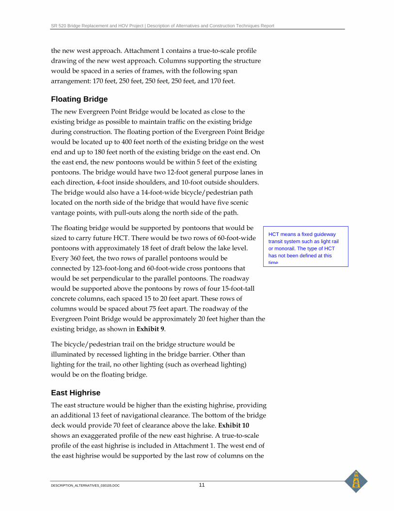
The floating bridge would be supported by pontoons that would be sized to carry future HCT. There would be two rows of 60-foot-wide pontoons with approximately 18 feet of draft below the lake level. Every 360 feet, the two rows of parallel pontoons would be connected by 123-foot-long and 60-foot-wide cross pontoons that would be set perpendicular to the parallel pontoons. The roadway would be supported above the pontoons by rows of four 15-foot-tall concrete columns, each spaced 15 to 20 feet apart. These rows of columns would be spaced about 75 feet apart. The roadway of the Evergreen Point Bridge would be approximately 20 feet higher than the existing bridge, as shown in Exhibit 9.
The bicycle/pedestrian trail on the bridge structure would be illuminated by recessed lighting in the bridge barrier. Other than lighting for the trail, no other lighting (such as overhead lighting) would be on the floating bridge.
East Highrise The east structure would be higher than the existing highrise, providing an additional 13 feet of navigational clearance. The bottom of the bridge deck would provide 70 feet of clearance above the lake. Exhibit 10 shows an exaggerated profile of the new east highrise. A true-to-scale profile of the east highrise is included in Attachment 1. The west end of the east highrise would be supported by the last row of columns on the
HCT means a fixed guideway transit system such as light rail or monorail. The type of HCT has not been defined at this time.

SR 520 Bridge Replacement and HOV Project | Description of Alternatives and Construction Techniques Report
DESCRIPTION_ALTERNATIVES_030105.DOC 12
floating pontoons. The east end of the highrise, closer to shore, would be supported by two sets of four columns. The sets of columns would be spaced approximately 300 feet apart. The structure would meet the existing highway elevation as it approaches Evergreen Point Road.
What is the 4-Lane Alternative without Expanded Pontoons Option? The 4-Lane Alternative without Expanded Pontoons would be exactly the same as the 4-Lane Alternative, except the pontoons for the floating portion of the Evergreen Point Bridge would be smaller. These smaller pontoons would eliminate the future possibility of HCT on the Evergreen Point Bridge, and would have 1 to 2 feet less draft (depth). Because the difference between this option and the 4-Lane Alternative is so small and has no discernable environmental effect, we have not discussed this option in any discipline reports, except for the Ecosystems Discipline Report in Appendix E.
Eastside
Evergreen Point Bridge/Eastside Connection Under the 4-Lane Alternative, the SR 520 east highrise would connect to land on the Eastside approximately 100 feet north of where it currently connects.
Evergreen Point Road Bridge The Evergreen Point Road bridge over SR 520 would be rebuilt to provide room to widen the highway. The bridge would have the same lane configuration as the existing structure. Eastbound and westbound transit stops would be located on the outside of the highway just east of Evergreen Point Road. Exhibit 11 shows the lane configuration at Evergreen Point Road.
84th Avenue Northeast Interchange The 84th Avenue Northeast bridge over SR 520 would be rebuilt and the interchange would be configured similarly to the interchange that exists today. A one-lane ramp would exit from SR 520 eastbound to become two lanes at the intersection. The loop on-ramp to SR 520 westbound would have one general purpose lane and one HOV bypass lane. Exhibit 12 shows the lane configuration at the 84th Avenue Northeast interchange.

SR 520 Bridge Replacement and HOV Project | Description of Alternatives and Construction Techniques Report
DESCRIPTION_ALTERNATIVES_030105.DOC 13
92nd Avenue Northeast Interchange The 92nd Avenue Northeast interchange would be configured similarly to the interchange that exists today. The 92nd Avenue bridge over SR 520 would be rebuilt to allow room to widen the highway. The SR 520 eastbound on-ramp would have one general purpose lane and one HOV bypass lane. The SR 520 westbound off-ramp would have one general purpose lane. Exhibit 13 shows the lane configuration at the 92nd Avenue Northeast interchange.
Transit stops would be located on the outside of the SR 520 eastbound and westbound lanes, just east and west of the 92nd Avenue Northeast interchange.
Bellevue Way Interchange Only minor changes would be made to the Bellevue Way interchange. The SR 520 westbound on-ramp from Lake Washington Boulevard Northeast would have one general purpose lane and one HOV bypass lane. An additional lane would be added to Lake Washington Boulevard Northeast between Northup Way and the westbound on-ramp. The SR 520 eastbound off-ramp to Bellevue Way Northeast would be rebuilt as a single general purpose lane ramp. No other changes would be made to the interchange. Exhibit 14 shows the lane configuration at the Bellevue Way interchange.
Would there be lids on the Eastside? The 4-Lane Alternative would not have lids. The Executive Committee agreed that because the 4-Lane Alternative would only replace the existing four lanes, it would only include required mitigation and no enhancements, such as lids.
Where would there be sound walls on the Eastside? Sound walls are proposed for the Eastside from west of the eastern shoreline of Lake Washington to just west of Bellevue Way, as shown in Exhibit 15. These walls would be virtually continuous through the entire area, except for breaks at Evergreen Point Road, 84th Avenue Northeast, and 92nd Avenue Northeast. Wall heights on the north side of the highway would vary from 8 feet on the Evergreen Point Bridge east approach structure to 20 feet near Evergreen Point Road. The sound wall height would then decrease to 10 to 14 feet near 80th Avenue Northeast and increase back up to 20 feet at 84th Avenue Northeast. Sound walls on the Eastside would total 21,575 feet in

SR 520 Bridge Replacement and HOV Project | Description of Alternatives and Construction Techniques Report
DESCRIPTION_ALTERNATIVES_030105.DOC 14
length, with heights ranging from 8 to 20 feet above the local area elevation.
What is the 6-Lane Alternative? The 6-Lane Alternative would include six lanes (two outer general purpose lanes and one inside HOV lane in each direction). SR 520 would be rebuilt from I-5 to 108th Avenue Northeast in Bellevue, with an auxiliary lane added on SR 520 eastbound from east of I-405 to 124th Avenue Northeast. Bridges across SR 520 would also be rebuilt. Roadway shoulders would meet current standards (10-foot inside shoulder and 10-foot outside shoulder).
Sound walls would be built along much of SR 520 in Seattle and the Eastside. As described in more detail later in this report, a 14-foot-wide bicycle/pedestrian path would be built along the north side of SR 520 through Montlake and across the Evergreen Point Bridge, and along the south side of SR 520 through the Eastside. A new bridge operations facility would be constructed under SR 520 and built into the east approach structure abutment on the east shore of Lake Washington. This alternative would also include stormwater treatment, electronic toll collection, and a flexible transportation plan. Unlike the 4-Lane Alternative, this alternative would add five 500-foot-long lids across SR 520 to reconnect communities along SR 520. Exhibits 16a through 16f show the footprint of the entire 6-Lane Alternative.
Seattle
I-5/SR 520 Interchange Under the 6-Lane Alternative, the connection of SR 520 to I-5 would be similar to the 4-Lane Alternative, but would include a reversible HOV ramp to connect the SR 520 HOV lanes to the I-5 express lanes, as shown in Exhibit 17. From westbound SR 520, one general purpose lane would exit to either East Roanoke Street or I-5 North, as it does today. Two general purpose lanes would connect to I-5 South using the existing structure across I-5. A new ramp over I-5 would provide a reversible HOV lane connecting the SR 520 HOV lanes to the I-5 express lanes. This reversible HOV lane would be used for the westbound to southbound connection in the mornings, and the northbound to eastbound connection in the evenings. Modifications to the I-5 express
Lids included under the 6-Lane Alternative would be located at:
• 10th and Delmar • Montlake • Evergreen Point • 84th Avenue Northeast • 92nd Avenue Northeast
SR 520 Bridge Replacement and HOV Project | Description of Alternatives and Construction Techniques Report
DESCRIPTION_ALTERNATIVES_030105.DOC 15
lanes would include construction of the new ramp over I-5 and reconstruction of the shoulders.
The connection of I-5 to SR 520 eastbound would be similar to the 4-Lane Alternative, with a few exceptions. From I-5 southbound, the existing tunnel would be rebuilt starting from the mid-point of the tunnel. From that point east, the tunnel would be rebuilt to include a wider 15-foot lane and 8-foot outside shoulder. From I-5 northbound, a wider two-lane on-ramp would connect to SR 520. The on-ramp would also include a bus-only ramp (that would operate only in the afternoon), which would connect the I-5 northbound mainline to the SR 520 eastbound HOV lane.
Bridges over SR 520 Four bridges over SR 520 would be rebuilt to provide room to widen SR 520: 10th Avenue East, Delmar Drive East, Montlake Boulevard, and 24th Avenue East. Both 10th Avenue East and Delmar Drive East would cross over SR 520 on the 500-foot-long 10th and Delmar lid. Montlake Boulevard would cross over SR 520 on the Montlake lid.
Portage Bay Bridge The Portage Bay Bridge would be up to 20 feet higher at certain locations than the existing structure, but would connect with the western land connection at the existing elevation. The bridge would have a more gradual slope than the existing bridge (see Exhibit 5, which shows a compressed horizontal view of the profile of the new bridge). A true-to-scale profile of the bridge is included in Attachment 1.
Compared to the bridge’s current 100-foot spacing, columns supporting the structure would generally be spaced in a series of five frames with the following span arrangement: 170 feet, 250 feet, 250 feet, 250 feet, and 170 feet. The side profile of the bridge would be built with haunched girders, as shown in Exhibit 6.
The bridge would be nine lanes wide because of four general purpose lanes, two HOV lanes, one transit-only lane, and two auxiliary lanes (westbound and eastbound) between Montlake Boulevard and I-5. The two HOV lanes would connect to the I-5 express lanes and to the I-5 mainline. The HOV lanes would only be functional westbound in the mornings and eastbound in the evenings.
SR 520 Bridge Replacement and HOV Project | Description of Alternatives and Construction Techniques Report
DESCRIPTION_ALTERNATIVES_030105.DOC 16
Montlake Interchange The new Montlake interchange would be similar to the 4-Lane Alternative, except for the HOV direct connection ramps and the transit stop locations, as shown in Exhibit 18. From SR 520 eastbound, one general purpose lane would exit to Montlake Boulevard, becoming three lanes at the intersection. From SR 520 westbound, one general purpose lane would exit to Montlake Boulevard, becoming two lanes at the intersection. The westbound SR 520 on-ramp would have two general purpose lanes and one HOV bypass lane. In addition, an HOV direct connection off-ramp would begin at Foster Island, weave over SR 520 to the north side of the highway, and exit to Montlake Boulevard northbound adjacent to the mainline exit. The eastbound SR 520 on-ramp would be a loop ramp with two general purpose lanes and one HOV bypass lane. The HOV bypass lane on the eastbound SR 520 on-ramp would weave north over SR 520 to connect directly to the inside HOV lane at Foster Island.
The new Montlake Boulevard bridge over SR 520 on the 500-foot-long lid would carry three lanes in each direction and left turn lanes. Montlake Place East and East Roanoke Street would be realigned just south of this interchange.
The Montlake transit stop on SR 520 would be located in the center of SR 520 to allow buses using the inside HOV lanes to access the stop. Pedestrian access to the transit stops would be from the Montlake lid via stairs and/or elevators.
Lake Washington Boulevard Ramps Under the 6-Lane Alternative, the existing Lake Washington Boulevard ramps and the ramps from the never completed R.H. Thompson Expressway would be removed. Exhibit 18 shows the lane configuration of the new Lake Washington Boulevard ramps. The westbound off-ramp from SR 520 to Lake Washington Boulevard would cross south under the SR 520 mainline and over more of the WSDOT-owned peninsula west of the Arboretum instead of over Union Bay as compared to today. The SR 520 eastbound on-ramp would be adjacent to the SR 520 westbound off-ramp on the peninsula. The ramps would intersect with Lake Washington Boulevard in the same place that they intersect today.

SR 520 Bridge Replacement and HOV Project | Description of Alternatives and Construction Techniques Report
DESCRIPTION_ALTERNATIVES_030105.DOC 17
The SR 520 mainline would shift north of the existing mainline beginning at the Lake Washington Boulevard ramps and continuing across Lake Washington.
What will the lids look like in Seattle? Two 500-foot-long lids would be built in Seattle: one connecting Roanoke/Portage Bay with North Capitol Hill and the other connecting the Montlake neighborhood. One lid would carry 10th Avenue East and Delmar Drive East; the other would carry Montlake Boulevard over SR 520. The lids would provide new landscaped, passive open space that would better connect the adjoining communities. Further design of the lids would be done if the 6-Lane Alternative is selected as the preferred alternative. WSDOT would work with the City of Seattle and the affected neighborhoods to complete the designs. Exhibit 19 shows some local residents’ ideas about the look and feel of the lids.
The lids are proposed to be 500 feet because this is the estimated maximum tunnel length allowed before installation of costly ventilation systems are required. If the 6-Lane Alternative were selected as the preferred alternative, WSDOT would conduct a detailed analysis to determine the exact maximum length for each lid at each location.
Would there be sound walls in Seattle? The proposed sound walls under the 6-Lane Alternative would be similar to those for the 4-Lane Alternative, and would run along both sides of SR 520 for most of the project corridor. Major differences would occur near the lids, and in some locations the wall heights would differ because of roadway geometry. Exhibit 20 shows the locations and heights of the proposed sound walls in Seattle.
The height measurements shown on these exhibits are the height of the wall above the grade of the highway; these measurements do not include any retaining walls that may be added during final design. The exception to this is the 8-foot-high sound wall between Lake Washington Boulevard and SR 520 in the Montlake area, where the 8 feet is assumed to be above the retaining wall of the depressed highway.
Sound walls in Seattle would total 26,583 feet in length, with heights ranging from 8 to 18 feet above the local area elevation.
Under the 6-Lane Alternative, the sound walls in Seattle on the north side of SR 520 would begin in the Portage Bay/Roanoke neighborhood

SR 520 Bridge Replacement and HOV Project | Description of Alternatives and Construction Techniques Report
DESCRIPTION_ALTERNATIVES_030105.DOC 18
and connect to the 10th and Delmar lid at both west and east ends, then end just past Boyer Avenue East in the same location as the 4-Lane Alternative. A second 1,100-foot-long sound wall would then start on the north side of SR 520 near the Seattle Yacht Club and continue east to the Montlake lid. This wall would be 10 feet high on the west end, increase to 12-feet-high, and then decrease to 8 feet near the Montlake lid.
A sound wall would continue east of the Montlake lid along the north side of SR 520 and along the westbound off-ramp through the Arboretum. This wall would range in height from 10 to 18 feet near Montlake, decrease to 8 feet across Foster Island, and end at the east end of the island in the same location as the 4-Lane Alternative’s sound wall.
A sound wall would also be built on the south side of SR 520, beginning at the east end of the 10th and Delmar lid and running continuously to the Montlake Boulevard eastbound off-ramp. This south wall would reach a maximum height of 14 feet near the 10th and Delmar lid, lowering to 10 feet from just east of Delmar Drive East all the way to its end point near Montlake Boulevard. This wall would be shorter than the wall under the 4-Lane Alternative because of the 10th and Delmar lid.
The south sound wall would continue east from the east side of the Montlake lid past Madison Park. The wall height would be 8 feet near Montlake Boulevard and through the Arboretum, and then increase to 10 feet adjacent to Madison Park.
Lake Washington Under the 6-Lane Alternative, the west approach of the Evergreen Point Bridge would begin farther west and would be higher and less steep than the current highrise (see Exhibit 5, which shows a compressed horizontal view of the profile of the new west approach). A true-to-scale profile of the west approach is included in Attachment 1. The SR 520 mainline would begin to rise at Union Bay, gradually attaining a maximum height of approximately 60 feet above the water (water level to bottom of bridge) just east of Foster Island. Columns supporting the structure would generally be spaced in a series of five frames with the following span arrangement: 170 feet, 250 feet, 250 feet, 250 feet, and 170 feet.
SR 520 Bridge Replacement and HOV Project | Description of Alternatives and Construction Techniques Report
DESCRIPTION_ALTERNATIVES_030105.DOC 19
Floating Bridge The new Evergreen Point Bridge would be located as close to the existing bridge as possible to maintain traffic on the existing bridge during construction. The floating portion of the Evergreen Point Bridge would be up to 400 feet north of the existing bridge on the west end and up to 180 feet north of the existing bridge on the east end. On the east end, the new pontoons would be within 5 feet of the existing pontoons. The bridge would have two general purpose lanes in each direction, one inside HOV lane in each direction, 10-foot inside shoulders, 10-foot outside shoulders, and a 14-foot-wide bicycle/pedestrian path located on the north side of the bridge. Five scenic vantage points with pull-outs would be spaced along the north side of the bicycle/pedestrian path.
The bridge would be supported by two parallel rows of 75-foot-wide pontoons with approximately 18 feet of draft. Every 360 feet, the two rows of parallel pontoons would be connected by cross pontoons, each 156 feet wide and 75 feet long. Four 15-foot-tall concrete columns on top of the cross pontoons would be spaced approximately every 60 feet apart to support the roadway. The roadway would be approximately 26 feet above water level.
The bicycle/pedestrian path on the bridge structure would be illuminated by recessed lighting in the bridge barrier for pedestrians and bicyclists using the path.
East Highrise Except for its width, the 6-Lane Alternative east highrise would be identical to the 4-Lane Alternative. The bottom of the east highrise would be 70 feet above lake level at the navigation channel, which is the same navigational clearance the 4-Lane Alternative would provide. Exhibit 10 shows an exaggerated profile of the new east highrise. Attachment 1 contains a true-to-scale profile of the east highrise. The first half of the highrise would be supported by the same series of rows of columns as on the floating pontoons. The second half of the highrise, closer to shore, would be supported by two sets of four columns. The sets of columns would be spaced approximately 300 feet apart. The highrise would meet the existing grade as it touches the eastern shore of Lake Washington.

SR 520 Bridge Replacement and HOV Project | Description of Alternatives and Construction Techniques Report
DESCRIPTION_ALTERNATIVES_030105.DOC 20
Eastside
Evergreen Point Bridge/Eastside Connection Under the 6-Lane Alternative, the east highrise would connect to land on the Eastside approximately 100 feet north of where it currently connects.
Evergreen Point Road Bridge The Evergreen Point Road bridge would be rebuilt as a 500-foot-long lid that would include Evergreen Point Road. Transit stops would be located in the center of SR 520 east of the Evergreen Point Road bridge across SR 520. Exhibit 21 shows the lane configuration at Evergreen Point Road.
84th Avenue Northeast Interchange The 84th Avenue Northeast interchange would be rebuilt and configured similarly to the 4-Lane Alternative. One lane would exit from SR 520 eastbound, becoming two lanes at the 84th Avenue Northeast intersection. The loop on-ramp to SR 520 westbound would be rebuilt with one general purpose lane and one HOV bypass lane. Exhibit 22 shows the lane configuration at the 84th Avenue Northeast interchange.
The 6-Lane Alternative would have an approximately 500-foot-long lid at the 84th Avenue Northeast intersection. The lid would carry the 84th Avenue Northeast over SR 520 and provide new open space to connect the Medina and Hunts Point communities.
92nd Avenue Northeast Interchange The 92nd Avenue Northeast interchange would be configured similarly to the 4-Lane Alternative. The SR 520 eastbound on-ramp would be rebuilt with one general purpose lane and one HOV bypass lane. The SR 520 westbound off-ramp would be rebuilt with one general purpose lane. Exhibit 23 shows the lane configuration at the 92nd Avenue Northeast interchange.
The 6-Lane Alternative would have a 500-foot-long lid that would carry 92nd Avenue Northeast over SR 520 and provide new open space to connect the Clyde Hill and Yarrow Point communities.

SR 520 Bridge Replacement and HOV Project | Description of Alternatives and Construction Techniques Report
DESCRIPTION_ALTERNATIVES_030105.DOC 21
Transit stops would be located in the center of SR 520 just underneath the 92nd Avenue Northeast lid for buses going both eastbound and westbound.
Bellevue Way Interchange The Bellevue Way interchange would be configured similarly to the interchange as it exists today. The Bellevue Way bridge over SR 520 would be rebuilt to allow more room for the widened SR 520 highway. The SR 520 westbound on-ramp from Lake Washington Boulevard Northeast would be rebuilt to begin approximately 150 feet farther north on Lake Washington Boulevard; it would have one general purpose lane and one HOV bypass lane. The SR 520 eastbound off-ramp to Bellevue Way Northeast would be rebuilt as a single general purpose lane ramp. The SR 520 eastbound off-ramp to Lake Washington Boulevard Northeast would be rebuilt as a single lane loop ramp. A portion of the SR 520 westbound on-ramp from Bellevue Way would be rebuilt as a tighter loop ramp, with one general purpose lane and one HOV bypass lane. Exhibit 24 shows the lane configuration at the Bellevue Way interchange.
The SR 520 westbound on-ramp from 108th Avenue Northeast would be rebuilt to align with the widened SR 520 mainline.
East of I-405 East of I-405, an auxiliary lane would be added from SR 520 eastbound to the 124th Avenue Northeast exit. The SR 520 bridge that crosses over Northup Way would be widened to accommodate the new lane. No changes would be made to the SR 520 westbound lanes east of I-405.
What would the lids look like on the Eastside? The 6-Lane Alternative would have three 500-foot-long lids at Evergreen Point Road, 84th Avenue Northeast, and 92nd Avenue Northeast. The lids would carry the existing local streets over SR 520 (Evergreen Point Road, 84th Avenue Northeast, and 92nd Avenue Northeast) and would provide new landscaped passive open space that would better reconnect the adjoining communities. Further design of the lids would be done if the 6-Lane Alternative were selected as the preferred alternative. WSDOT would work with the affected jurisdictions to complete the designs. Exhibit 25 includes drawings of local residents’ ideas about the look and feel of the lids.
SR 520 Bridge Replacement and HOV Project | Description of Alternatives and Construction Techniques Report
DESCRIPTION_ALTERNATIVES_030105.DOC 22
The lids are proposed to be 500 feet in length because this is the estimated maximum tunnel length allowed before installation of costly ventilation systems are required. If the 6-Lane Alternative were selected as the preferred alternative, WSDOT would conduct a detailed analysis to determine the exact maximum length for each lid at each location.
Would there be sound walls on the Eastside? Under the 6-Lane Alternative, sound walls are proposed for the Eastside from west of the eastern shoreline of Lake Washington to just west of Bellevue Way, as shown in Exhibit 26. The sound walls would be continuous throughout the entire area except for breaks at Evergreen Point Road, 84th Avenue Northeast, and 92nd Avenue Northeast, where the sound walls would be integrated with the lids. The project would add about 19,500 feet of sound walls on the Eastside, with heights ranging from 8 to 20 feet above the local area elevation. Higher sound walls are necessary in areas where residents are located uphill from the project corridor.
What features are similar in the 4-Lane and 6-Lane Alternatives? The 4-Lane and 6-Lane Alternatives both include a flexible transportation plan (FTP), tolls, a continuous bicycle/pedestrian path, stormwater treatment, new lighting, and a bridge operations facility.
Bicycle/Pedestrian Path Both the 4-Lane and 6-Lane Alternatives would provide a new continuous bicycle and pedestrian path across the Evergreen Point Bridge, where there currently is no path today. The path would connect to existing paths in Montlake and Medina. The path would be located on the north side of the Evergreen Point Bridge with five scenic vantage pull-outs.
Seattle A 14-foot-wide bicycle/pedestrian path would be reconstructed just south of the SR 520 eastbound Montlake off-ramp. The path would connect to the existing Bill Dawson Trail near Montlake Park and extend north underneath the off-ramp and SR 520. The path would then turn east and follow the northern edge of SR 520 just outside of the sound wall in two lanes—one lane connecting to Montlake Boulevard

SR 520 Bridge Replacement and HOV Project | Description of Alternatives and Construction Techniques Report
DESCRIPTION_ALTERNATIVES_030105.DOC 23
and the other continuing along SR 520 under Montlake Boulevard. The path would fork north and east, connecting to the existing trail in East Montlake Park and continuing east along the north side of the Evergreen Point Bridge.
In addition, another bicycle/pedestrian path beginning in East Montlake Park would extend south under SR 520 and connect to a proposed new trail in the Arboretum, creating a loop trail. The portion of the existing Arboretum Waterfront Trail that crosses under SR 520 at Foster Island would also be restored after construction of the highway.
There would be no bicycle/pedestrian path along SR 520 west of Montlake Boulevard. Exhibit 27 shows the proposed bicycle/ pedestrian path connections in Montlake.
Eastside At the east highrise to the Evergreen Point Bridge, the bicycle/ pedestrian path would turn south and continue under SR 520, and then proceed east along the south side of the highway. The bicycle/ pedestrian path would lie south of the proposed sound wall.
The bicycle/pedestrian path would be constructed under local streets to provide a continuous, nonstop route. Connections would be made to Evergreen Point Road, 84th Avenue Northeast, and 92nd Avenue Northeast. The existing bicycle/pedestrian overpass just east of Evergreen Point Road would be rebuilt to accommodate the wider highway. The path would then branch to connect to two end points: The path would connect to Northeast 33rd Street in Clyde Hill to the south; the other connection to the north would include a bicycle/ pedestrian-only bridge over SR 520 that would then connect into Northeast Points Drive in Kirkland.
The existing Points Loop Trail would remain on the north side of SR 520 for pedestrian use only. Several sections of the trail would be rebuilt to the north to accommodate the widening of the highway.
Stormwater Treatment Generally, stormwater treatment facilities would be in approximately the same locations for both the 4-Lane and 6-Lane Alternatives, although the 6-Lane Alternative facilities would be larger. A map showing the locations of the proposed facilities is shown in Exhibit 28. Each treatment facility has a distinct designation on the map (e.g.,

SR 520 Bridge Replacement and HOV Project | Description of Alternatives and Construction Techniques Report
DESCRIPTION_ALTERNATIVES_030105.DOC 24
CC-1); these designations are provided in parentheses in the discussion below to assist the reader in finding the facility on the map.
Seattle In the Lake Union basin, project engineers have selected emerging technology best management practices (BMPs) for treating stormwater quality. The specific BMP would be chosen at the time of final design; this BMP will meet Highway Runoff Manual (WSDOT 2004) requirements for basic treatment. A space-efficient underground facility would be constructed on the I-5 roadside between the southbound and express lanes at approximately East Louisa Street in the existing right-of-way (LU-1). It would treat the portion of the SR 520 mainline west of 10th Avenue East and the I-5 flyover ramp that would be added by the project.
In the Portage Bay basin, the project would construct a water quality wet vault under the Portage Bay Bridge between East Boyer and the shoreline to provide basic stormwater treatment (PB-1). The vault could be an open-top structure located in the existing right-of-way that would discharge to an existing outfall location under the bridge.
A stormwater treatment wetland would be constructed between SR 520, the Montlake Boulevard eastbound off-ramp, and the shoreline of Portage Bay (PB-2). This stormwater treatment wetland, which would be one of four wetlands proposed for the project, would be designed to resemble natural wetlands that would blend into the surrounding landscape (see the photograph to the right, which shows an example of a stormwater treatment constructed in South King County).
Exhibit 29 is a diagram showing how a stormwater treatment wetland works. Stormwater treatment wetlands are considered an enhanced treatment BMP because they remove some of the dissolved metals from stormwater, in addition to removing total suspended solids. These wetlands provide enhanced treatment by using multiple cells and wetland vegetation. The first cell is a presettling cell that collects
An example of a stormwater treatment wetland - South King County

SR 520 Bridge Replacement and HOV Project | Description of Alternatives and Construction Techniques Report
DESCRIPTION_ALTERNATIVES_030105.DOC 25
sediment and pollutants. After treatment in the first cell, water flows into the wetland cell, where the combined biological action of plants and bacteria, along with settling, biofiltration, biodegradation, and bioaccumulation, provide further treatment for dissolved metals and other pollutants.
In the Union Bay basin, stormwater would be treated at a number of stormwater treatment wetlands. Run-off from SR 520 between Montlake Boulevard and approximately the R.H. Thompson peninsula would be conveyed in new storm drains to a stormwater treatment wetland in McCurdy and East Montlake Parks (where the Museum of History and Industry [MOHAI] parking lot is currently located) (UB-1). Treated discharges from the wetland would be conveyed north to a new outfall or an existing city outfall in the Montlake Cut. If the existing outfall were used, it would likely have to be upgraded with a larger pipe.
Another stormwater treatment wetland in the Union Bay basin would be located in the existing WSDOT right-of-way on the peninsula where the current Lake Washington Boulevard ramps are located. The wetland would treat stormwater from the elevated Lake Washington Boulevard ramps (UB-2).
Also in the Union Bay basin, 14 or 15 bridge column wetlands would be integrated into the design and construction of the bridge columns, as shown in Exhibit 30. These wetlands would have the same standard components and functions as a typical stormwater treatment wetland; however, they would be constructed in a nontraditional location. The bridge column wetlands would be constructed inside cofferdams, which are used to dewater the column footings during construction. Rather than removing the cofferdams after the columns are built, the stormwater treatment wetlands would be created inside of them (CH2M HILL and Parametrix 2004). Stormwater runoff from approximately the R.H. Thomson peninsula to just east of Foster Island would first be treated in sediment chambers (larger than typical catch basins) located just below the roadway at the columns. Most of the sediment would be removed in these sediment chambers. The runoff would then be conveyed to the stormwater treatment wetlands located at the base of the columns on the south side of the bridge for additional removal of dissolved metals and total suspended solids. Finally, discharges would flow into submerged outfalls at each column. In addition to this treatment, the bridge approach would be cleaned with a
SR 520 Bridge Replacement and HOV Project | Description of Alternatives and Construction Techniques Report
DESCRIPTION_ALTERNATIVES_030105.DOC 26
high-efficiency vacuum sweeper on a scheduled basis to collect pollutants from the roadway before they can get into the stormwater.
Lake Washington The floating portion of the proposed Evergreen Point Bridge would consist of a column-supported bridge deck on elevated pontoons. Traditional stormwater treatment strategies are difficult and/or structurally infeasible on the floating bridge. The proposed treatment strategy is a series of treatments, including, in order:
1. High efficiency sweeping of the bridge deck
2. Modified catch basins with oil traps (larger capacity than standard sumps and oil traps) to collect sediment and oil
3. Spill lagoons located in the enclosed space between the main pontoons and cross-pontoons
Exhibits 31, 32, and 33 show what the spill lagoons would look like and how they would work. The spill lagoons would be located between sets of paired pontoons. Stormwater would flow across the road surface on the bridge to the inside gutter, and then move down the gutter and through grated inlets into the modified catch basins. The stormwater would ultimately discharge to the spill control lagoons.
The 4-Lane Alternative would have a 3-foot-wide lagoon, and the 6-Lane Alternative would have a 6-foot-wide lagoon. These lagoons would serve two purposes:
• To provide containment for any spilled hydrophobic materials such as oil and other petroleum products, as well as any oil and grease accumulating on the bridge pavement from the normal operation of vehicles crossing the bridge.
• To mix and diffuse water-soluble pollutants, such as metals in stormwater. The mixing process would be aided by ambient lake currents, which would cause turbulent mixing and diffusion as the stormwater disperses from the discharge pipes.
Eastside Two facilities would be constructed in the Fairweather Bay basin (Medina and Hunts Point). A wet vault would be located between the roadway slope and the 80th Avenue Northeast cul-de-sac to treat flows from the west portion of the basin (FB-1). The vault would discharge

SR 520 Bridge Replacement and HOV Project | Description of Alternatives and Construction Techniques Report
DESCRIPTION_ALTERNATIVES_030105.DOC 27
flows to the storm drain in 80th Avenue Northeast and then to Fairweather Bay. The storm drain and outfall at Fairweather Bay would likely need upgrading due to the increased flow rates.
Under the 4-Lane Alternative, a wet pond would be constructed inside the loop ramp at the 84th Avenue Northeast westbound on-ramp (FB-2b). Treated flows would discharge to the west beneath the proposed bicycle/pedestrian path. In addition, an underground detention vault would be constructed under the trail just east of Fairweather Creek.
The loop ramp would be an impractical location for a facility under the 6-Lane Alternative because of the lid; therefore, enhanced treatment and flow control would be provided in a vault near the outfall to the creek (FB-2a). Treated and detained flows would discharge to an upgraded outfall at Fairweather Creek.
In the Cozy Cove basin (Hunts Point and Yarrow Point), flow control and wet vaults with an enhanced treatment BMP would be located under the existing Points Loop Trail and the proposed bicycle/ pedestrian path (CC-1). Treated and detained stormwater would then flow to Cozy Cove Creek.
In the Yarrow Bay basin (Kirkland and Bellevue), new and existing storm drains would convey runoff to three stormwater treatment facilities. A wet vault with an enhanced treatment BMP would be located on the shoulder of Northeast Points Drive and treat flows into the Yarrow Bay wetland (YC-1). An upgraded outfall would accommodate increased flows, dissipate erosive velocities, and spread flows into the wetlands. Flows to an existing 36-inch culvert near 92nd Avenue Northeast would be eliminated or reduced to alleviate existing downstream erosion.
Another wet vault with enhanced treatment is proposed under the enforcement area on the westbound on-ramp from Lake Washington Boulevard (only for the 6-Lane Alternative) (YC-2). The treated stormwater would flow into the east tributary of Yarrow Creek.
Also in the Yarrow Bay basin, a stormwater treatment wetland with flow control would be constructed between SR 520, Lake Washington Boulevard, and Northeast Point Drive (YC-3). This site is currently occupied by two commercial buildings and an espresso stand. The wetland would discharge to both the east tributary and mainstem of Yarrow Creek.
SR 520 Bridge Replacement and HOV Project | Description of Alternatives and Construction Techniques Report
DESCRIPTION_ALTERNATIVES_030105.DOC 28
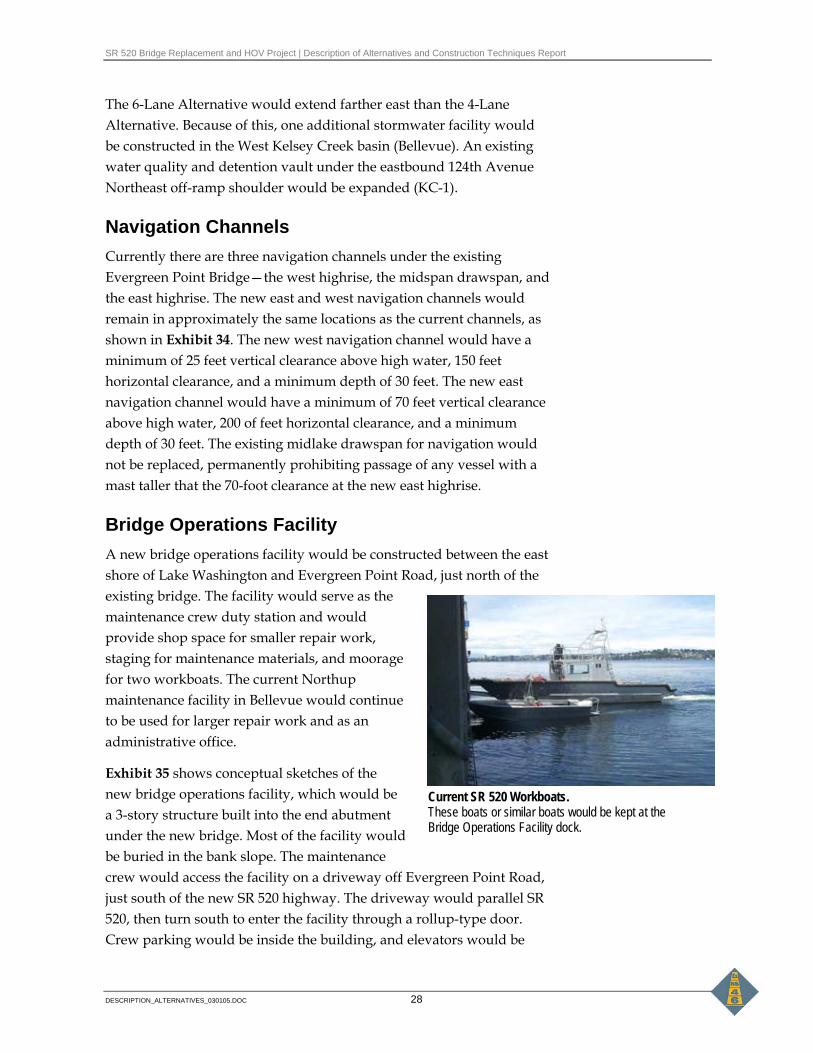
Current SR 520 Workboats. These boats or similar boats would be kept at the Bridge Operations Facility dock.
The 6-Lane Alternative would extend farther east than the 4-Lane Alternative. Because of this, one additional stormwater facility would be constructed in the West Kelsey Creek basin (Bellevue). An existing water quality and detention vault under the eastbound 124th Avenue Northeast off-ramp shoulder would be expanded (KC-1).
Navigation Channels Currently there are three navigation channels under the existing Evergreen Point Bridge—the west highrise, the midspan drawspan, and the east highrise. The new east and west navigation channels would remain in approximately the same locations as the current channels, as shown in Exhibit 34. The new west navigation channel would have a minimum of 25 feet vertical clearance above high water, 150 feet horizontal clearance, and a minimum depth of 30 feet. The new east navigation channel would have a minimum of 70 feet vertical clearance above high water, 200 of feet horizontal clearance, and a minimum depth of 30 feet. The existing midlake drawspan for navigation would not be replaced, permanently prohibiting passage of any vessel with a mast taller that the 70-foot clearance at the new east highrise.
Bridge Operations Facility A new bridge operations facility would be constructed between the east shore of Lake Washington and Evergreen Point Road, just north of the existing bridge. The facility would serve as the maintenance crew duty station and would provide shop space for smaller repair work, staging for maintenance materials, and moorage for two workboats. The current Northup maintenance facility in Bellevue would continue to be used for larger repair work and as an administrative office.
Exhibit 35 shows conceptual sketches of the new bridge operations facility, which would be a 3-story structure built into the end abutment under the new bridge. Most of the facility would be buried in the bank slope. The maintenance crew would access the facility on a driveway off Evergreen Point Road, just south of the new SR 520 highway. The driveway would parallel SR 520, then turn south to enter the facility through a rollup-type door. Crew parking would be inside the building, and elevators would be

SR 520 Bridge Replacement and HOV Project | Description of Alternatives and Construction Techniques Report
DESCRIPTION_ALTERNATIVES_030105.DOC 29
constructed inside the building to transport vehicles, crews, and materials to the lake and boat dock.
The dock would extend 70 feet into the water, where two finger piers would provide moorage for two boats. The grated dock would be 20 feet wide out to the first finger pier, with a jib crane for loading materials and equipment onto the boats, and a spill response cabinet. The dock would be 10 feet wide beyond the first finger pier.
Pontoon Anchors Like the existing floating bridge, both alternatives would anchor the floating pontoons to the lake bottom to hold the bridge in place. The existing anchors would likely be left in place when the old bridge structure is removed.
Two main types of anchors would be used for the new bridge:
• Gravity anchors would be used in the dense, harder lakebed materials of Lake Washington. These anchors would consist of large concrete blocks or boxes stacked on top of one another.
• For most of the floating bridge, fluke anchors would be used in the soft bottom sediments of the lake. These anchors would be installed using a combination of their own weight and water or air-jetting to set them below the mud line. The fluke anchors would be 32 to 35 feet across in width.
Both types of anchors would be connected to the floating pontoons with steel cables ranging in size from 1.5 to 3 inches in diameter. The anchors would extend approximately 690 to 700 feet out from the bridge. For the protection of boaters, boat use would be restricted within 200 feet of the bridge.
Approximately 22 anchors would be installed along each of the north and south sides of the new bridge structure, for a total of 44 anchors. See Exhibit 9, which shows the approximate location of these anchors. Exhibit 36 shows how the different anchor types would be installed.
Existing Sign on Evergreen Point Bridge. A similar sign would be posted on the new floating bridge to protect boaters from the submerged cables.
Construction of Fluke Anchor
SR 520 Bridge Replacement and HOV Project | Description of Alternatives and Construction Techniques Report
DESCRIPTION_ALTERNATIVES_030105.DOC 30
Lighting New lighting along SR 520 would be similar to existing lighting and would use fixtures that shield sideways glare. The bicycle/pedestrian path would not be lit separately in Seattle.
Aurora Borealis Sculptures The Aurora Borealis sculptures east of Foster Island in Union Bay would be removed to accommodate the new alignment. The sculptures would not be reinstalled because they would not be visible from the highway.
Tolls Exhibit 37 shows the toll rates that would be all imposed on single-occupancy vehicles (SOV) traveling in each direction across the Evergreen Point Bridge. The peak hour, one-way rate of $6.50 has been calculated in 2030 dollars to account for inflation (this amount is equivalent to $3.35 today). Both the 4-Lane and 6-Lane Alternatives would be tolled.
Transit service, registered vanpools, and carpools with three or more people would not have to pay the toll. An electronic toll collection (ETC) system would be used to allow traffic to operate at free-flow conditions as opposed to manual toll collection, which would require drivers to reduce speeds to pass through a toll collection plaza to pay. The ETC system would consist of an overhanging fixture beside the roadway, similar to a lighting fixture, which would monitor vehicles with a “card reader” as they crossed the bridge.
Users who are required to pay the toll would have transponders or “cards” in or on their vehicles that would be read by the card reader. All SOV travelers, as opposed to just commuters, would be required to use the transponders to cross the Evergreen Point Bridge. Two types of transponders that could be used include:
1) A permanent transponder. This transponder attaches permanently to a vehicle’s windshield. In many places, they are sold at kiosks that resemble automatic teller machines (ATMs). In the future, they may be available at actual ATMs.
2) A portable transponder. This transponder could be transferred between multiple vehicles.
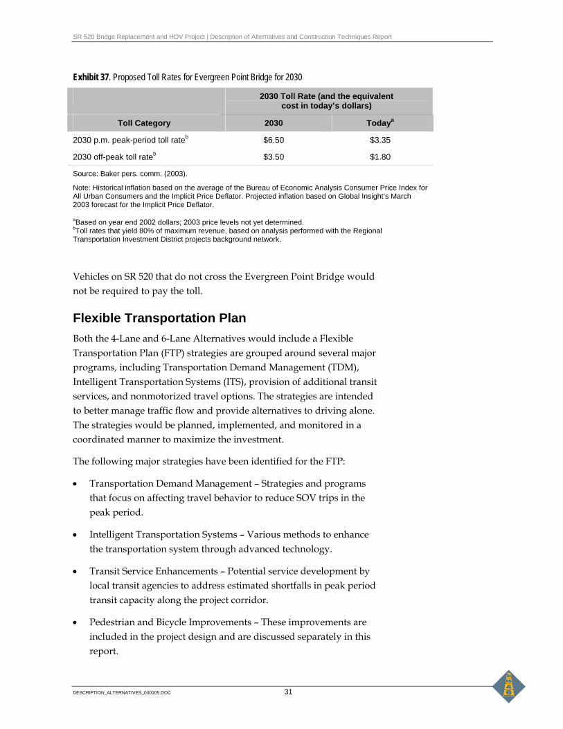
SR 520 Bridge Replacement and HOV Project | Description of Alternatives and Construction Techniques Report
DESCRIPTION_ALTERNATIVES_030105.DOC 31
Exhibit 37. Proposed Toll Rates for Evergreen Point Bridge for 2030
2030 Toll Rate (and the equivalent cost in today’s dollars)
Toll Category 2030 Todaya
2030 p.m. peak-period toll rateb $6.50 $3.35
2030 off-peak toll rateb $3.50 $1.80
Source: Baker pers. comm. (2003).
Note: Historical inflation based on the average of the Bureau of Economic Analysis Consumer Price Index for All Urban Consumers and the Implicit Price Deflator. Projected inflation based on Global Insight’s March 2003 forecast for the Implicit Price Deflator.
aBased on year end 2002 dollars; 2003 price levels not yet determined. bToll rates that yield 80% of maximum revenue, based on analysis performed with the Regional Transportation Investment District projects background network.
Vehicles on SR 520 that do not cross the Evergreen Point Bridge would not be required to pay the toll.
Flexible Transportation Plan Both the 4-Lane and 6-Lane Alternatives would include a Flexible Transportation Plan (FTP) strategies are grouped around several major programs, including Transportation Demand Management (TDM), Intelligent Transportation Systems (ITS), provision of additional transit services, and nonmotorized travel options. The strategies are intended to better manage traffic flow and provide alternatives to driving alone. The strategies would be planned, implemented, and monitored in a coordinated manner to maximize the investment.
The following major strategies have been identified for the FTP:
• Transportation Demand Management – Strategies and programs that focus on affecting travel behavior to reduce SOV trips in the peak period.
• Intelligent Transportation Systems – Various methods to enhance the transportation system through advanced technology.
• Transit Service Enhancements – Potential service development by local transit agencies to address estimated shortfalls in peak period transit capacity along the project corridor.
• Pedestrian and Bicycle Improvements – These improvements are included in the project design and are discussed separately in this report.

SR 520 Bridge Replacement and HOV Project | Description of Alternatives and Construction Techniques Report
DESCRIPTION_ALTERNATIVES_030105.DOC 32
The FTP also includes goals associated with implementation of TDM and ITS, including those elements that will involve cooperation among several agencies. WSDOT intends to facilitate a collaborative effort with local jurisdictions, transit agencies, and other appropriate parties to establish an effective SR 520 corridor FTP program. WSDOT will also facilitate efforts to find funding for elements of the FTP that would not be funded by WSDOT.
What coordination would be required? TDM-related efforts during construction have been included in the overall funding estimates for the SR 520 Bridge Replacement and HOV Project. Costs for ITS-related elements are also included in these funding estimates. The TDM funding would be equivalent to approximately 1.0 percent of total project construction costs, while the ITS funding is supported by an itemized estimate.
WSDOT is committed to facilitate a process that will bring together representatives from local jurisdictions and various other agencies to implement those elements of the FTP that would not be funded as part of project construction. These are discussed later in this section. The goal of the coordination process is to agree on FTP implementation and a funding process for those elements that would not be funded as part of the construction budget.
What FTP elements would be funded as part of the project construction? The project’s construction costs would include TDM and ITS elements.
TDM Elements TDM elements would focus on maintenance of traffic (MOT) during construction (see Exhibit 38). The estimated costs presented in Exhibit 38 will be refined in discussions between public and private agencies to develop more detailed TDM strategies to address the needs of the traveling public.

SR 520 Bridge Replacement and HOV Project | Description of Alternatives and Construction Techniques Report
DESCRIPTION_ALTERNATIVES_030105.DOC 33
Exhibit 38. Construction Period TDM Plan Elements
Construction-Period TDM Plan Elements 4-Lane Alternative
(Estimate) 6-Lane Alternative
(Estimate) Oversight Program: Program coordination, administration, monitoring and evaluation
$2,500,000 $3,500,000
HOV/Toll Marketing and Public Information Programs: New intensive HOV marketing for transit and rideshare, toll facility promotion, corridor-focused public information program during construction, trip planning services
$11,000,000 $14,500,000
Vanpooling (includes I-90) / Vanshare: Van acquisition, intensive marketing for vanpool formation, leased rideshare park-and-pool, VanShare routes
$8,500,000 $13,000,000
Total $22,000,000 $31,000,000
The MOT strategies would start 1 year before construction and continue throughout the entire construction period. For the 4-Lane Alternative, MOT strategies would be implemented over 7 to 9 years (starting with construction through project completion). For the 6-Lane Alternative, MOT strategies would be implemented over 9 to 11 years.
As shown in Exhibit 38, MOT strategy costs for the 4-Lane Alternative are estimated at $22 million, while the 6-Lane Alternative cost is estimated at $31 million. The 6-Lane Alternative MOT costs are higher to cover the longer MOT implementation period, which would be 2 years longer than under the 4-Lane Alternative. More specific information for the MOT implementation plan (number of vans, focus and emphasis of public information, etc.) will be developed and coordinated with the design process and development of construction documents for the new bridge. The MOT implementation plan will be developed in partnership with public and private sector agencies involved in TDM implementation in the SR 520 corridor.
ITS Elements Currently, WSDOT uses a variety of ITS strategies to manage traffic along the SR 520 corridor, including variable message signs (VMS) and the existing Transportation System Management Center (TSMC). The ITS elements included in the FTP would enhance and expand the existing WSDOT ITS program to address traffic management during construction of the SR 520 Bridge Replacement and HOV Project. These ITS elements include additional support to the TSMC and new ITS equipment.
Transportation System Management Center

SR 520 Bridge Replacement and HOV Project | Description of Alternatives and Construction Techniques Report
DESCRIPTION_ALTERNATIVES_030105.DOC 34
Support would be provided to the TSMC to address MOT needs during project construction. The cost range for this support is $9 million for the 4-Lane Alternative and $15 million for the 6-Lane Alternative.
ITS equipment would be purchased and installed during project construction, including Incident Management System and ramp metering. The cost estimates for the individual elements of ITS during construction are included in Exhibit 39. Costs for the complete ITS program is estimated at $38.5 million for the 4-Lane Alternative and $52.2 million (2004 dollars) for the 6-Lane Alternative construction periods. These costs estimates include adjustments for risk and inflation to the middle of 2012 per the project CEVP data.
Exhibit 39. Construction Period ITS Elements
ITS Elements
4-Lane Alternative ($) million
6-Lane Alternative ($) million
Maintain operation of existing communication infrastructure 2.0 1.9
Maintain existing VMS and Highway Advisory Radio system in the corridor and approaches to the corridor 0.5 0.5
Upgrade existing VMS in the corridor and on approaches to the corridor 0.5 0.5
Expand VMS system 0.7 0.6
Maintain operation of existing ramp meters 1.5 1.5
Update/expand ramp meter system 1.7 1.6
Expand/upgrade communications infrastructure 2.9 2.8
Maintain operation of existing camera system 1.0 1.0
Update/expand camera system 1.3 1.2
Maintain data collection system 0.7 0.6
Update/expand data collection system 0.5 0.5
Maintain roving incident response program* 3.8 6.1
Expand roving incident response program* 5.1 7.9
Enhance staffing for the TSMC* 0.1 0.3
Enhance TSMC 15.2 24.3
Maintain and enhance traffic management strategies 0.3 0.3
Arterial signal and surveillance improvements 0.7 0.6
Total 38.5 52.2
Source: WSDOT Transportation Demand Management Plan (WSDOT 2004) for SR 520 Bridge Replacement and HOV Project Flexible Transportation Plan. (Parametrix 2004). HAR: Highway Advisory Radio TSMC = Transportation System Management Center. VMS = Variable message sign. * Inflation only, not adjusted for risk.

SR 520 Bridge Replacement and HOV Project | Description of Alternatives and Construction Techniques Report
DESCRIPTION_ALTERNATIVES_030105.DOC 35
The FTP provides for replacement, relocations, expansion, and enhancements of ITS elements and strategies already in use on the SR 520 corridor. These elements would be in operation both during and after the construction phase of the project. During the construction phase, ITS elements would help to mitigate construction-induced traffic congestion on the freeway caused by construction. The following further describes the ITS elements that would be used in the SR 520 corridor.
Incident Management System Listed below are elements of a proposed Incident Management System.
• Maintain operation of existing communication infrastructure. This would be necessary for successful use of the other elements of the ITS infrastructure.
• Upgrade existing VMS in the SR 520 corridor and on approaches to the corridor. This would be a key component of the ongoing traffic management strategy; the signs would support both planned closures and incident management.
• Expand VMS system. This would increase the effective coverage of the VMS system and allow for more specific messages as needed for incidents and maintenance.
• Maintain operation of existing camera system. This would aid in quickly detecting and responding to incidents in the corridor, decreasing clearance time, reducing secondary accidents, and providing motorists with valuable information.
• Expand camera system. New permanent camera installations would supplement or replace existing camera system.
• Maintain data collection system. This would be necessary for successful use of the other elements of the ITS infrastructure and for tracking both long-term trends and measuring short-term effects.
• Expand data collection system. An expanded data collection system would improve the quality of driver information; allow more complete information to be presented to planners, legislators,
Example of Variable Message Signs
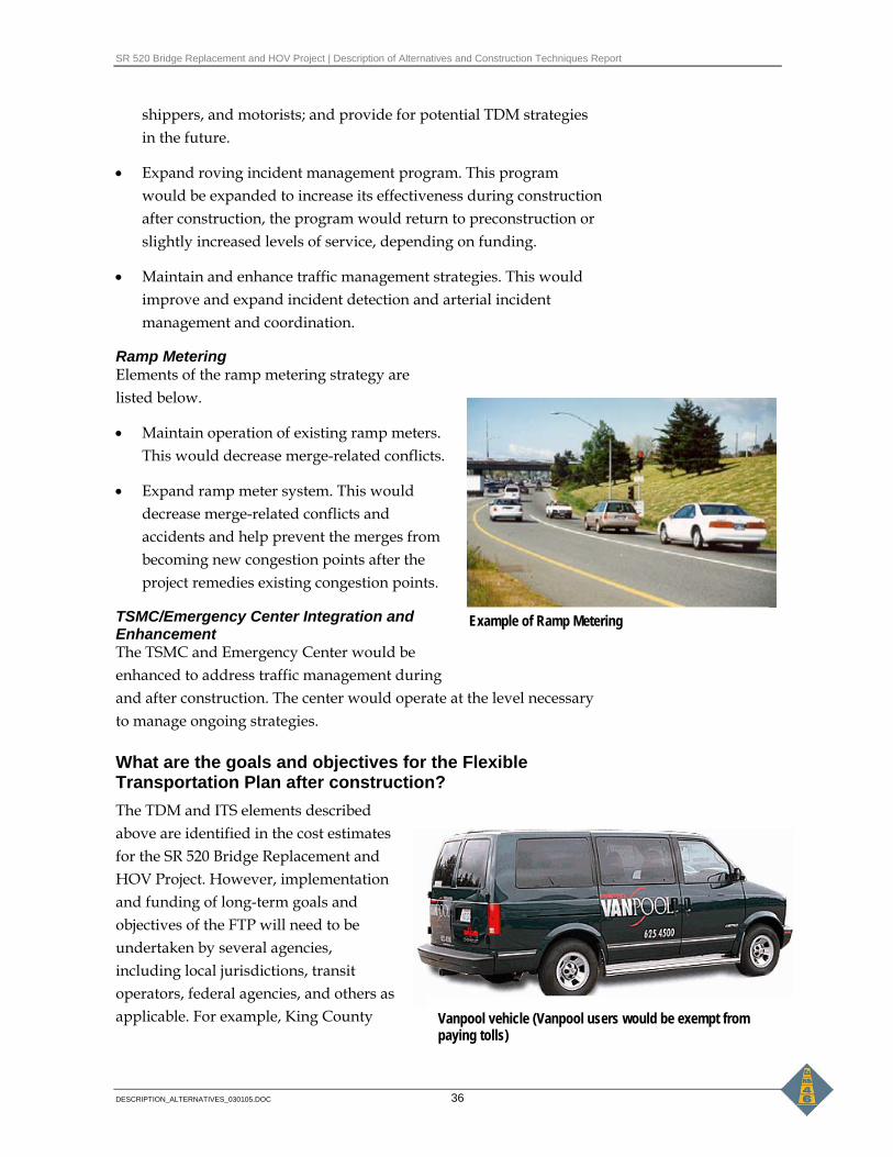
SR 520 Bridge Replacement and HOV Project | Description of Alternatives and Construction Techniques Report
DESCRIPTION_ALTERNATIVES_030105.DOC 36
Vanpool vehicle (Vanpool users would be exempt from paying tolls)
shippers, and motorists; and provide for potential TDM strategies in the future.
• Expand roving incident management program. This program would be expanded to increase its effectiveness during construction after construction, the program would return to preconstruction or slightly increased levels of service, depending on funding.
• Maintain and enhance traffic management strategies. This would improve and expand incident detection and arterial incident management and coordination.
Ramp Metering Elements of the ramp metering strategy are listed below.
• Maintain operation of existing ramp meters. This would decrease merge-related conflicts.
• Expand ramp meter system. This would decrease merge-related conflicts and accidents and help prevent the merges from becoming new congestion points after the project remedies existing congestion points.
TSMC/Emergency Center Integration and Enhancement The TSMC and Emergency Center would be enhanced to address traffic management during and after construction. The center would operate at the level necessary to manage ongoing strategies.
What are the goals and objectives for the Flexible Transportation Plan after construction? The TDM and ITS elements described above are identified in the cost estimates for the SR 520 Bridge Replacement and HOV Project. However, implementation and funding of long-term goals and objectives of the FTP will need to be undertaken by several agencies, including local jurisdictions, transit operators, federal agencies, and others as applicable. For example, King County
Example of Ramp Metering

SR 520 Bridge Replacement and HOV Project | Description of Alternatives and Construction Techniques Report
DESCRIPTION_ALTERNATIVES_030105.DOC 37
Metro and Community Transit also operate vanpool programs and would need to be involved in follow-up planning and implementation for various ridesharing programs. Also, several ITS-related strategies would need to be coordinated with local jurisdictions.
The goals and objectives would serve as the framework for long-term FTP strategies. FTPs for all corridor projects in the region will be coordinated to ensure benefits for mutual users of these corridors. For example, if major TDM efforts were underway in downtown Seattle as part of the Alaskan Way Viaduct and Seawall Project, those efforts could contribute to non-HOV/transit travel reductions along the SR 520 corridor.
Following is a list of the goals and objectives for the FTP.
• Goal 1—Provide Alternatives to SOV Travel.
− Objective A: Increase transit and HOV speed and reliability along the project corridor (SR 520 between I-5 and I-405).
− Objective B: Increase transit service in peak periods to accommodate forecasted demand.
− Objective C: Increase HOV capacity to meet needs during project construction.
− Objective D: Improve bicycle and pedestrian circulation along the project corridor.
• Goal 2—Provide Incentives to Reduce Trips or use Non-SOV Modes.
− Objective E: Reduce barriers to transit and vanpools.
− Objective F: Encourage the management of price and supply of long-term commuter parking at major employment centers (downtown Seattle, downtown Bellevue, and Overlake); local jurisdictions will be responsible for implementation of any changes.
− Objective G: Provide information to help users choose best travel options.
• Goal 3—Manage Traffic to Reduce Congestion and Delay.
− Objective H: Manage mainline traffic flow and improve safe merging.
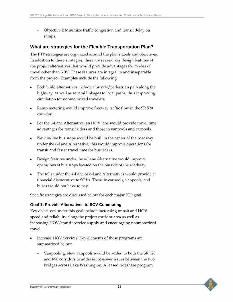
SR 520 Bridge Replacement and HOV Project | Description of Alternatives and Construction Techniques Report
DESCRIPTION_ALTERNATIVES_030105.DOC 38
− Objective I: Minimize traffic congestion and transit delay on ramps.
What are strategies for the Flexible Transportation Plan? The FTP strategies are organized around the plan’s goals and objectives. In addition to these strategies, there are several key design features of the project alternatives that would provide advantages for modes of travel other than SOV. These features are integral to and inseparable from the project. Examples include the following:
• Both build alternatives include a bicycle/pedestrian path along the highway, as well as several linkages to local paths, thus improving circulation for nonmotorized travelers.
• Ramp metering would improve freeway traffic flow in the SR 520 corridor.
• For the 6-Lane Alternative, an HOV lane would provide travel time advantages for transit riders and those in vanpools and carpools.
• New in-line bus stops would be built in the center of the roadway under the 6-Lane Alternative; this would improve operations for transit and faster travel time for bus riders.
• Design features under the 4-Lane Alternative would improve operations at bus stops located on the outside of the roadway.
• The tolls under the 4-Lane or 6-Lane Alternatives would provide a financial disincentive to SOVs. Those in carpools, vanpools, and buses would not have to pay.
Specific strategies are discussed below for each major FTP goal.
Goal 1: Provide Alternatives to SOV Commuting Key objectives under this goal include increasing transit and HOV speed and reliability along the project corridor area as well as increasing HOV/transit service supply and encouraging nonmotorized travel.
• Increase HOV Services. Key elements of these programs are summarized below:
− Vanpooling: New vanpools would be added to both the SR 520 and I-90 corridors to address crossover issues between the two bridges across Lake Washington. A leased rideshare program,

SR 520 Bridge Replacement and HOV Project | Description of Alternatives and Construction Techniques Report
DESCRIPTION_ALTERNATIVES_030105.DOC 39
marketing and support for vanpool formation, and support for operating the vanpool program would also be provided.
− VanShare: VanShare provides commute connections between residences or employment sites and public transportation facilities and services such as park-and-ride lots and rail stations. The VanShare program can increase HOV travel by extending and increasing access to bus and rail service.
− Increase Transit Service: By 2030, daily regional transit service in King, Pierce, and Snohomish counties (measured in annual bus hours) is forecasted to be about 70 percent greater than today. This reflects an annual growth rate of about 2 percent per year. This estimate is consistent with past trends in transit service growth, as calculated by transit providers. Service is assumed to grow at a greater rate during off-peak hours. Peak-period service is expected to grow at a rate of about 1 percent per year.
Transit ridership forecasts for the project indicate that buses would operate at a maximum seating capacity by 2030 and still not serve the total person demand. In the SR 520 corridor, an additional 64 buses would be needed for the 4-Lane Alternative and 65 buses for the 6-Lane Alternative. This level of service increase plus other support will likely not be feasible within existing funding levels of affected transit operators – King County Metro, Sound Transit, and Community Transit. The FTP will include facilitation to help obtain required additional resources for transit and other service that help achieve operational efficiencies for the corridor.
• Improve Bicycle and Pedestrian Circulation. Bicycle and pedestrian improvements are included as part of the project. See Bicycle/Pedestrian Path for a description of these improvements which are included in both the 4-Lane and 6-Lane Alternatives.
Metro Bus

SR 520 Bridge Replacement and HOV Project | Description of Alternatives and Construction Techniques Report
DESCRIPTION_ALTERNATIVES_030105.DOC 40
Goal 2: Provide Incentives to Reduce Trips or Use Non-SOV Modes • Provide HOV/Toll Marketing and Public Information. This strategy
would complement and increase the effectiveness of all the other TDM plan elements by targeting and influencing commute trips. It includes a core program with new intensive, corridor-focused HOV marketing for transit and rideshare; new information and an education campaign for the toll facilities; and personalized trip planning assistance for travelers in the SR 520 corridor.
• Support Employer-Based Programs. Employer-based programs would reduce commute trips or shift commute trips out of peak periods by:
− Providing incentives and resources for Commute Trip Reduction and non-Commute Trip Reduction employers.
− Providing new promotion and implementation assistance for increasing telecommuting.
− Supporting Transportation Management Associations (such as the Greater Redmond Transportation Management Associates) in trip reduction efforts aimed at employers.
• Support Land Use as Traffic Demand Management. This strategy would encourage local projects that increase human-powered connections to transit service along the SR 520 corridor.
• Include Other Demand Management Programs. Other programs would enhance the effects of other TDM elements. These programs include:
− Transit support programs, including custom bus services and innovative fare programs such as Flexpass or residential pass programs
− Noncommute trip TDM programs, including support and incentives for system management during special events and efficient movement of freight and commercial vehicles
− Performance-based incentives for commute trip and noncommute trip applications
− Management of price and supply of long-term commuter parking at major employment centers (downtown Seattle, downtown Bellevue, and Overlake) ; local jurisdictions would be responsible for implementing this strategy.

SR 520 Bridge Replacement and HOV Project | Description of Alternatives and Construction Techniques Report
DESCRIPTION_ALTERNATIVES_030105.DOC 41
Goal 3: Maintain Flexible Transportation Plan After strategies have been agreed to by appropriate agencies, an FTP implementation plan and an oversight program would be developed.
• Develop Implementation Plan. WSDOT, in partnership with jurisdictions in the project area, transit agencies, public and private sector TDM providers, and employers, would develop a 20-year implementation plan for TDM strategies. The implementation plan could include:
− A phased implementation schedule with identification of early action/construction mitigation strategies and post-construction/operational efficiency strategies
− A funding plan
− Roles and responsibilities for various implementers of the plan
− Administrative structure for the plan's programs
− A framework to integrate the plan with existing local, regional, and state TDM programs
• Provide Oversight Program. The oversight program would provide for adaptive management to administer, monitor, evaluate, and adjust implementation of the TDM strategies over the 20-year plan period. It would also include the TDM goals supported and implemented by the corridor TDM and land use agreement and provide for coordination of TDM programs for the SR 520 corridor.
What are the potential costs for the Flexible Transportation Plan? Costs for major elements of the proposed FTP strategies are discussed below.
20-Year TDM Plan Costs for some FTP strategies have been identified in the Draft TDM Plan for the SR 520 Bridge Replacement and HOV Project. These strategies and related costs are identified in Exhibit 40 for the 4-Lane and 6-Lane Alternatives. TDM elements include the project-specific items that focus on maintenance of traffic (MOT) during construction. MOT strategy costs for the 4-Lane Alternatives are estimated at $22 million and at $31 million for the 6-Lane Alternative (see Exhibit 38).

SR 520 Bridge Replacement and HOV Project | Description of Alternatives and Construction Techniques Report
DESCRIPTION_ALTERNATIVES_030105.DOC 42
In addition to the MOT-related items, the proposed 20-year TDM plan for the SR 520 corridor would include strategies that would occur after project construction. These strategies would focus on increasing the operational efficiency of the new bridge facility by supporting increases in HOV mode shares (rideshare, transit).
Funding for the post-construction strategies would come from a variety of local, state, and federal sources. As presented in Exhibit 40, total costs are estimated at $180 million for the 4-Lane Alternative and $160 million for the 6-Lane Alternative. Development of the implementation plan for the post-construction strategies, including a funding plan, would occur at the same time as the MOT implementation plan.
Intelligent Transportation Systems Other potential FTP strategies that would incur costs beyond the construction period include those relating to ITS. WSDOT has estimated these costs for the construction period (see Exhibit 40), but has not estimated costs for maintaining ITS after project construction is completed.
Transit Service Enhancements As part of the FTP effort, WSDOT will facilitate discussion about strategies to improve corridor transit service that would enhance overall operations of the SR 520 corridor. Transit service strategies would address the gap between estimated transit demand along the corridor and estimated supply. More bus service could be added during and/or after construction; however, additional funding support would be required. The facilitation process will include the identification of potential funding sources and amounts.
To determine transit costs, a service program and identification of capital equipment (such as additional buses and potential additional maintenance/operations facilities) would have to be undertaken. Increasing park-and-ride lot capacity to help riders access additional services could also be considered.
Approximately $7.1 million in additional annual transit operating costs would likely be needed for either the 4-Lane or 6-Lane Alternatives (2004 dollars), plus purchase of 65 more buses (4-Lane Alternative) or 66 more buses (6-Lane Alternative).

SR 520 Bridge Replacement and HOV Project | Description of Alternatives and Construction Techniques Report
DESCRIPTION_ALTERNATIVES_030105.DOC 43
Exhibit 40. 20-Year Flexible Transportation Plan
TDM Plan Elements
4-Lane Alternative (million $)
6-Lane Alternative (million $)
Implementation Plan and Oversight Program Program establishment, coordination, monitoring and evaluation
Program Subtotal $11,500,000 $11,500,000 HOV/Toll Marketing and Public Information Programs New intensive HOV marketing for transit and rideshare, information program before and during construction, toll facility promotion, corridor-focused public information program during construction, trip planning assistance
Program Subtotal $45,000,000 $37,500,000 Vanpooling (includes I-90)/Vanshare Van acquisitions, intensive marketing and vanpool formation assistance, leased park-and-pool, VanShare routes
Program Subtotal $36,500,000 $36,500,000 Employer-based Programs Work schedule options, incentives for employers affected by commute trip reduction (CTR) law and employers not affected by CTR law, assistance for Transportation Management Associations
Program Subtotal $40,000,000 $32,000,000 Land Use as TDM Local projects to increase nonmotorized connectivity to transit service
Program Subtotal $8,500,000 $8,500,000 Other TDM Programs Transit support programs (custom bus service, fare media), non-commute trip and freight trip incentives, performance-based incentive program
Program Subtotal $38,500,000 $34,000,000
Total 20-Year TDM Plan $180,000,000 $160,000,000
Estimated Funding from Construction 22,000,000 31,000,000
Required Additional Funding Support 158,000,000 129,000,000
Potential Funding Strategies Funds for the phased implementation of the FTP could be sought from a variety of sources. Sources could include WSDOT (statewide Commute Trip Reduction/TDM funding sources), transit agencies, jurisdictional programs, federal grants such as Congestion Management for Air Quality, private sector programs, and tax credits.

SR 520 Bridge Replacement and HOV Project | Description of Alternatives and Construction Techniques Report
DESCRIPTION_ALTERNATIVES_030105.DOC 44
WSDOT would develop a funding plan in partnership with affected transit agencies and jurisdictions. A funding plan can provide a phased financing and implementation approach for the TDM plan as well as other FTP strategies. Funding efforts would be coordinated with major TDM, HOV, and transit incentives for other major corridor efforts such as the SR 99 Alaskan Way Viaduct and Seawall Project and the I-405 Congestion Relief and BRT Project.

SR 520 Bridge Replacement and HOV Project | Description of Alternatives and Construction Techniques Report
DESCRIPTION_ALTERNATIVES_030105.DOC 45
Construction Techniques This section summarizes the major construction activities anticipated for completion of the SR 520 Bridge Replacement and HOV Project. More details about structures, including structure types, foundations, retaining walls, and sound walls are available in the Bridge and Structures Working Paper prepared by the Trans-Lake Washington Project Team, August 14, 2002.
The project is at a preliminary level of design. Thus far, the design team has determined that the build alternatives would mostly be constructed within the footprint boundaries of the alternatives shown in this Draft EIS. The project footprint includes a 5-foot buffer beyond the edge of the pavement or retaining wall. During the final design of the preferred alternative, we may identify other small areas outside of the footprint boundaries that the contractor might need in order to build the project. These areas would be used on a temporary basis during construction and restored when construction is complete. WSDOT plans to pursue agreements with local property owners to facilitate construction in these areas. If it is not possible to reach consensus about temporary use of local properties, other design options that would not require these properties would be pursued.
Generally, as described above, construction would occur within the permanent project footprint. The exception would be construction of the temporary work and detour bridges, which would result in additional temporary effects.
What types of construction techniques would be used? Contractors are typically allowed to choose their own construction techniques. The following descriptions are a reasonable estimate of how the project could be constructed.
Roadway Reconstruction The 4-Lane and 6-Lane Alternatives would remove existing pavement and replace it with concrete pavement. Asphalt that is removed would generally be recycled. Existing below-ground material (which consists of pavement-based materials that lie underneath the roadway surface)
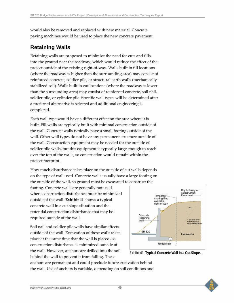
SR 520 Bridge Replacement and HOV Project | Description of Alternatives and Construction Techniques Report
DESCRIPTION_ALTERNATIVES_030105.DOC 46
would also be removed and replaced with new material. Concrete paving machines would be used to place the new concrete pavement.
Retaining Walls Retaining walls are proposed to minimize the need for cuts and fills into the ground near the roadway, which would reduce the effect of the project outside of the existing right-of-way. Walls built in fill locations (where the roadway is higher than the surrounding area) may consist of reinforced concrete, soldier pile, or structural earth walls (mechanically stabilized soil). Walls built in cut locations (where the roadway is lower than the surrounding area) may consist of reinforced concrete, soil nail, soldier pile, or cylinder pile. Specific wall types will be determined after a preferred alternative is selected and additional engineering is completed.
Each wall type would have a different effect on the area where it is built. Fill walls are typically built with minimal construction outside of the wall. Concrete walls typically have a small footing outside of the wall. Other wall types do not have any permanent structure outside of the wall. Construction equipment may be needed for the outside of soldier pile walls, but this equipment is typically large enough to reach over the top of the walls, so construction would remain within the project footprint.
How much disturbance takes place on the outside of cut walls depends on the type of wall used. Concrete walls usually have a large footing on the outside of the wall, so ground must be excavated to construct the footing. Concrete walls are generally not used where construction disturbance must be minimized outside of the wall. Exhibit 41 shows a typical concrete wall in a cut slope situation and the potential construction disturbance that may be required outside of the wall.
Soil nail and soldier pile walls have similar effects outside of the wall. Excavation of these walls takes place at the same time that the wall is placed, so construction disturbance is minimized outside of the wall. However, anchors are drilled into the soil behind the wall to prevent it from falling. These anchors are permanent and could preclude future excavation behind the wall. Use of anchors is variable, depending on soil conditions and
Exhibit 41. Typical Concrete Wall in a Cut Slope.

SR 520 Bridge Replacement and HOV Project | Description of Alternatives and Construction Techniques Report
DESCRIPTION_ALTERNATIVES_030105.DOC 47
height of walls. Short soldier pile walls may not require anchors. Exhibits 42 and 43 show typical soil nail and soldier pile walls, respectively, in a cut slope situation and the potential construction disturbance that may take place outside of the wall.
Cylinder pile walls minimize the amount of construction required outside of the wall. This type of wall is used only in special conditions because the cylinders can be very large (up to 10 feet in diameter) and a cylinder pile wall is very expensive to build.
Sound Walls In general, WSDOT uses precast panels to construct sound walls along highways; however, they sometimes also use cast-in-place concrete or masonry. The type of foundation depends on the wall, the location, and the surrounding soil. Foundations are typically spread footings, trench footings, or shafts. The face of the sound walls would be designed to present a unified visual appearance when viewed from within the highway corridor. This will take place later in the design phase of the project. Some sound walls that face communities and would therefore be seen regularly by residents would have a detailed texture to align with a slower viewing speed and ability to observe more detail.
Local Street Crossings Bridges that carry local streets over SR 520 would be constructed using precast girders and cast-in-place decks. Box girders would not be used because the false work required for construction would reduce the vertical clearance of the highway during construction. Girder placement over the existing highway would require short-term closures
Exhibit 42. Typical Soil Nail Wall in a Cut Slope Exhibit 43. Typical Soldier Pile Wall in a Cut Slope

SR 520 Bridge Replacement and HOV Project | Description of Alternatives and Construction Techniques Report
DESCRIPTION_ALTERNATIVES_030105.DOC 48
or detours of highway traffic. Closures for girder placement are typically performed at night and would require three to four closures for each bridge.
Local street crossings would remain open during construction of the replacement crossing structures, except for Delmar Drive East. Delmar Drive East would be closed during construction because of its low traffic volume and available detour options.
There are several possible methods for construction of new bridges over SR 520, including the following:
• Under the 6-Lane Alternative, build a portion of the lid next to the existing structure. Detour traffic onto the lid, demolish the existing structure, and then build the new structure. Lid designs may have to be modified to accommodate this scenario.
• Build the new structure parallel to the existing structure at a temporary location. Detour traffic onto the new structure at the temporary location and then demolish the existing structure. Construct new foundations at the proposed location and move the new structure into place. This option would require closing the local street for about 8 hours when the new structure is being moved to its final location. Because there is no other access for Evergreen Point Road and 84th Avenue Northeast, both roads would remain open to emergency vehicles during the move of the new structures. The new structures would always have enough room for at least one emergency vehicle to cross during the moves. Construction crews would coordinate with emergency service providers prior to closure.
• Build a temporary foundation parallel to the existing structure. Close traffic and move the existing structure to the temporary foundation. Shift traffic to the existing structure at the new location and then build the new structure. This option would require closing the local street for about 8 hours when the existing structure is moved to the temporary location. Because there is no other access for Evergreen Point Road and 84th Avenue Northeast, both roads would remain open to emergency vehicles during the move of the existing structures. The new structures would always have enough room for at least one emergency vehicle to cross during the moves. Construction crews would coordinate with emergency service providers prior to closure.

SR 520 Bridge Replacement and HOV Project | Description of Alternatives and Construction Techniques Report
DESCRIPTION_ALTERNATIVES_030105.DOC 49
• Build a temporary structure parallel to the existing structure. Shift traffic onto the temporary structure, demolish the existing structure, and then build the new structure.
In most cases, moving traffic onto the temporary structures would require the traffic speed to be significantly less that the posted speed limit.
Lids Under the 6-Lane Alternative, lids would be constructed using precast girders across the SR 520 mainline. The girders would be spaced between 5 and 10 feet apart. For safety reasons, SR 520 traffic would be shifted around the construction area to nonconstruction SR 520 lanes when the girders are being placed. Closure of the HOV lane on the Eastside may be necessary.
In most cases, the lids would be constructed in three sections across the width of SR 520; four lanes of traffic would be shifted under a single section of the lid. This would allow each section of the lid to be constructed without closing the general purpose lanes.
Bridge Foundations Once the preferred alternative is selected, additional geotechnical investigations will be necessary before finally deciding on the most appropriate foundation type. Structures on land would have spread footings, shaft, or pile foundations. Structures over water are assumed to have shaft or pile foundations. If the design/build approach were used, the contractor would select the type of foundation.
The three options for constructing the bridge foundations are described below.
Option 1 – Spread Footing Spread footings require a relatively shallow, concrete pad that would provide adequate square footage to transmit the weight of the bridge to the soil. This type of footing requires soils that can support the weight of the bridge.
Option 2 – Shaft Shaft installation requires steel casing to achieve high-quality footing and column construction. When a shaft is installed in water, it has a large steel shell that isolates the shaft construction from the water to

SR 520 Bridge Replacement and HOV Project | Description of Alternatives and Construction Techniques Report
DESCRIPTION_ALTERNATIVES_030105.DOC 50
allow dewatering and column construction. This steel shell acts as the forms for the shaft construction and the installation of reinforcing steel.
In recent years, the use of drilled shaft foundations has become very common. Shafts require minimum space, can carry very heavy loads, and provide sufficient lateral load capacity for seismic design loads. Shaft construction is relatively quiet because it minimizes the noise effects of pile driving.
Shafts constructed in an environmentally sensitive area would require sedimentation control to prevent spilling excavated material, water, or drilling slurry (if required). This is accomplished in a number of ways, depending on the soil conditions and the contractor’s equipment and preference. Some possible methods are:
• Drive a larger containment shell first, and then proceed with shaft construction inside the shell. Such an outer shell makes it easier to contain any water or slurry that is displaced when the concrete is poured.
• Use a self-contained facility, such as Baker Tanks, to handle and reuse the slurry, if slurry is necessary for drilling.
Option 3 – Pile Pile foundations consist of driven piles covered by a concrete cap to support the column. This foundation type is easier to install than shafts, especially if boulders are encountered during soils exploration. Piling installations are noisy. Wherever possible, pile foundations would be avoided, especially near noise-sensitive areas such as hospitals and residential neighborhoods.
The potential for spillage of excavated material is eliminated if pile foundations are used. Driving the piles generates vibrations and pressure waves in the water. An air bubble curtain could be built around a construction site to minimize underwater percussion waves from steel piling that could harm fish.
Temporary Work and Detour Bridges To safely construct the proposed 4-Lane and 6-Lane Alternatives, WSDOT would build temporary work bridges beside the Portage Bay Bridge and a detour bridge in the Arboretum area to allow vehicle traffic and construction activity to occur simultaneously in the project corridor. Much of the temporary work area would be located within the
SR 520 Bridge Replacement and HOV Project | Description of Alternatives and Construction Techniques Report
DESCRIPTION_ALTERNATIVES_030105.DOC 51
footprint of the proposed build alternatives. At times, the construction limits would extend beyond this area.
At Portage Bay, 30-foot-wide temporary work bridges would be located on the north and south sides of the existing bridge. Exhibits 44 and 45 show the locations of the work bridges that would be constructed for the 4-Lane and 6-Lane Alternatives, respectively. At Union Bay and the Arboretum, a 60-foot-wide temporary detour bridge would be located on the south side of the existing bridge; this temporary bridge would provide a detour route for traffic on the existing west approach to the Evergreen Point Bridge. The existing bridge would be used for work access and as a work platform. Exhibits 46 and 47 show the locations of the temporary detour bridges in Union Bay and at the Arboretum.
The temporary bridges would remain in place for approximately 4 to 5 years, depending on the location and the selected alternative. The 4-Lane Alternative would need approximately 1,800 steel piles for the temporary bridges, and the 6-Lane Alternative would need approximately 1,600. All temporary bridge support structures would be removed at the end of the construction period and the areas would be restored.
Construction of the temporary work and detour bridges would begin by driving steel piles, installing a cap beam, and then installing the superstructure. A crane on the completed portion of the work bridge would reach out to construct the next span. Piles would be 18 to 24 inches in diameter. For detour bridges, the superstructure would be capped with an asphalt overlay.
Installing the foundations and erecting the new superstructure would take place from finger piers extending from the work bridge.
Once traffic is shifted to the new SR 520 roadway, the detour bridge would be used to erect additional work bridges for construction of the new Lake Washington Boulevard ramps and demolition of the existing ramps. All work and detour bridges and finger piers would then be removed; removal would begin at one end and work backwards by reaching out and removing the previous span.
Where the existing bridge is used as workspace, some reinforcement of the bridge may be necessary to support the load of the cranes. The weight of a crane when lifting a heavy load is greater than the weight used for designing the bridge for general traffic. During construction, the bridge would be analyzed to determine the specific reinforcement

SR 520 Bridge Replacement and HOV Project | Description of Alternatives and Construction Techniques Report
DESCRIPTION_ALTERNATIVES_030105.DOC 52
requirements. Reinforcement includes driving piles and erecting additional beams to provide more support of the existing bridge girders.
Permanent Bridges
Precast Girders Most of the mainline structures on Portage Bay and the west approach would be precast concrete girders with span lengths of about 250 feet. The span length would be achieved by splicing the girders and post-tensioning them continuously over several spans.
All construction of the new bridge structure would probably occur from the existing bridge and the finger piers. The exact method of foundation construction has not yet been determined. It is clear that the contractor would have to take precautions to prevent excavated material from falling into the water and wet concrete from spilling during concrete placement.
Girder erection would be accomplished using cranes situated on the existing bridge and finger piers. Some 30 to 50 piles could be necessary to stabilize the partially erected girder system, depending on the erection scheme. Night closures may be required to place some of the girders.
Cast-in-Place Box Girders Cast-in-place box girders would be used for the east approach structure and possibly for the Lake Washington Boulevard ramps in the Arboretum area. Construction would require the use of false work to support the vertical and/or horizontal loads of the formwork, reinforcing steel, wet concrete, and live loads, including finishing
machines, until the bridge is substantially complete. Contractors use a wide variety of materials for falsework, including manufactured shoring tower systems (Waco-Shore X, Pafco, and Patent), 12x12 wood posts, driven round wood pilings, steel H piles, and pipe piles.
Spans for the box girders would typically range up to 250 feet.
Special Bridge Types Other types of structures that could be used in certain locations include transition spans and steel box girders.

SR 520 Bridge Replacement and HOV Project | Description of Alternatives and Construction Techniques Report
DESCRIPTION_ALTERNATIVES_030105.DOC 53
Transition spans between the floating bridge and the fixed approach structures would be constructed offsite. These spans would be barged to the opening and lifted into place using barge-mounted cranes.
Steel box girders could be used for ramp construction. The steel boxes would be lifted into place using cranes. Concrete decks would then be poured in place on top of the steel beam. Concrete slab structures may be used where the bicycle/pedestrian path crosses under roadways. This structure type can only be used for very short spans. The slabs may be either cast-in-place or precast.
Floating Bridge Pontoons Each pontoon and anchor of the floating bridge would be constructed offsite at a graving dock. A graving dock is a large, gated channel that is excavated next to the shoreline of a body of water. When a group of pontoons and anchors has been constructed, the graving dock is flooded to float them. The graving dock gate is then opened and a tug boat tows the pontoons and anchors out of the graving dock into the open water.
This EIS assumes that environmental review of the graving dock is covered by the Hood Canal Bridge Retrofit and East Half Replacement projects. Work dates at the graving dock and opening of the gate would be subject to fish restrictions. All applicable screening requirements would be followed during pumping operations.
Although the superstructure of many of the pontoons would be constructed offsite at the graving dock, some superstructures would be constructed on the pontoons after they are floated into Lake Washington.
The pontoons and anchors would be towed from the graving dock and floated into Lake Washington, where they would be anchored and connected to adjacent pontoons. Pontoons that cross the existing midlake navigation channel would be the last ones floated into position to maintain the open navigation channel for as long as possible. Final onsite assembly of the bridge would involve connecting the superstructure between adjacent pontoons, barrier construction, and completion work on the superstructure.
Removal of Existing Structures The superstructures of the existing bridge (approach spans, ramps, and Portage Bay Bridge) consists of precast concrete girders with cast-in-
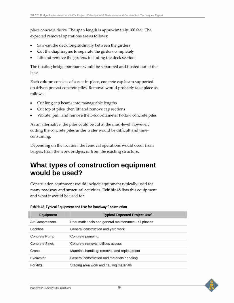
SR 520 Bridge Replacement and HOV Project | Description of Alternatives and Construction Techniques Report
DESCRIPTION_ALTERNATIVES_030105.DOC 54
place concrete decks. The span length is approximately 100 feet. The expected removal operations are as follows:
• Saw-cut the deck longitudinally between the girders • Cut the diaphragms to separate the girders completely • Lift and remove the girders, including the deck section
The floating bridge pontoons would be separated and floated out of the lake.
Each column consists of a cast-in-place, concrete cap beam supported on driven precast concrete piles. Removal would probably take place as follows:
• Cut long cap beams into manageable lengths • Cut top of piles, then lift and remove cap sections • Vibrate, pull, and remove the 5-foot-diameter hollow concrete piles
As an alternative, the piles could be cut at the mud-level; however, cutting the concrete piles under water would be difficult and time-consuming.
Depending on the location, the removal operations would occur from barges, from the work bridges, or from the existing structure.
What types of construction equipment would be used? Construction equipment would include equipment typically used for many roadway and structural activities. Exhibit 48 lists this equipment and what it would be used for.
Exhibit 48. Typical Equipment and Use for Roadway Construction
Equipment Typical Expected Project Usea
Air Compressors Pneumatic tools and general maintenance - all phases
Backhoe General construction and yard work
Concrete Pump Concrete pumping
Concrete Saws Concrete removal, utilities access
Crane Materials handling, removal, and replacement
Excavator General construction and materials handling
Forklifts Staging area work and hauling materials

SR 520 Bridge Replacement and HOV Project | Description of Alternatives and Construction Techniques Report
DESCRIPTION_ALTERNATIVES_030105.DOC 55
Exhibit 48. Typical Equipment and Use for Roadway Construction
Equipment Typical Expected Project Usea
Haul Trucks Materials handling, general hauling
Jackhammers Pavement removal
Loader General construction and materials handling
Pavers Roadway paving
Pile Drivers Support for structure and hillside
Power Plants General construction use, nighttime work
Pumps General construction use, water removal
Pneumatic Tools Miscellaneous construction work
Service Trucks Repair and maintenance of equipment
Tractor Trailers Material removal and delivery
Utility Trucks General project work
Vibratory equipment Shore up hillside to prevent slides and soil compacting
Welders General project work
Where are the construction staging areas? Because there is limited right-of-way available outside the project footprint, areas for construction staging are limited and would be similar for both alternatives.
In Seattle, a potential area for construction staging is the MOHAI site, which is assumed to be acquired for the project. The unused R.H. Thompson Expressway Ramps, as well as the closed Lake Washington Boulevard ramps, could also be used as staging areas.
On the Eastside, it is anticipated that the construction staging areas would lie within the project footprint. The existing westbound SR 520 HOV lane would be closed during construction and used as a staging area. The By-the-Way Espresso and adjacent buildings, located in Kirkland just west of Lake Washington Boulevard and north of SR 520, would be acquired as the site for a stormwater treatment wetland and could also serve as a staging area during construction.

SR 520 Bridge Replacement and HOV Project | Description of Alternatives and Construction Techniques Report
DESCRIPTION_ALTERNATIVES_030105.DOC 56
How long would it take to construct the project? For the most part, the 4-Lane and 6-Lane Alternatives would be constructed in the same manner, so they are discussed together in this section. Differences between the 4-Lane and 6-Lane Alternatives are identified where appropriate.
The construction staging described below is not the only way the project could be built, but it demonstrates a logical sequence. The construction segments and techniques described below would be similar for the 4-Lane and 6-Lane Alternatives, although the length of time to construct each segment would generally be longer for the 6-Lane Alternative.
The project has been divided into nine construction segments. For this Draft EIS, we have assumed that all segments would be constructed together as one project, although they could be constructed separately with separate schedules. Construction segments and the construction duration for each segment are shown in Exhibit 49.
Exhibit 49. Construction Duration of the 4-Lane and 6-Lane Alternatives
Segment 4-Lane Alternative 6-Lane Alternative
I-5/SR 520 Interchange 13 months 15 months
Portage Bay Bridge 28 months 28 months
Montlake Interchange 20 months 26 months
West Approach to Evergreen Point Bridge 41 months 52 months
Floating Section of Evergreen Point Bridge 66 months 75 months
East Approach to Evergreen Point Bridge 35 months 43 months
Evergreen Point Road 20 months 25 months
84th Avenue Northeast and 92nd Avenue Northeast 27 months 23 months
Bellevue Way, 108th Avenue Northeast, and 124th Avenue Northeast
N/A 13 months
Temporary work bridges would have to be built before construction could begin on the Portage Bay Bridge and Evergreen Point Bridge west approach. These would take about 6 to 8 months to construct.
Two lanes in each direction would be maintained on SR 520 and the temporary detour bridge during peak weekday traffic. On- and off-ramps would be reconstructed while open to traffic, with lane shifts, as
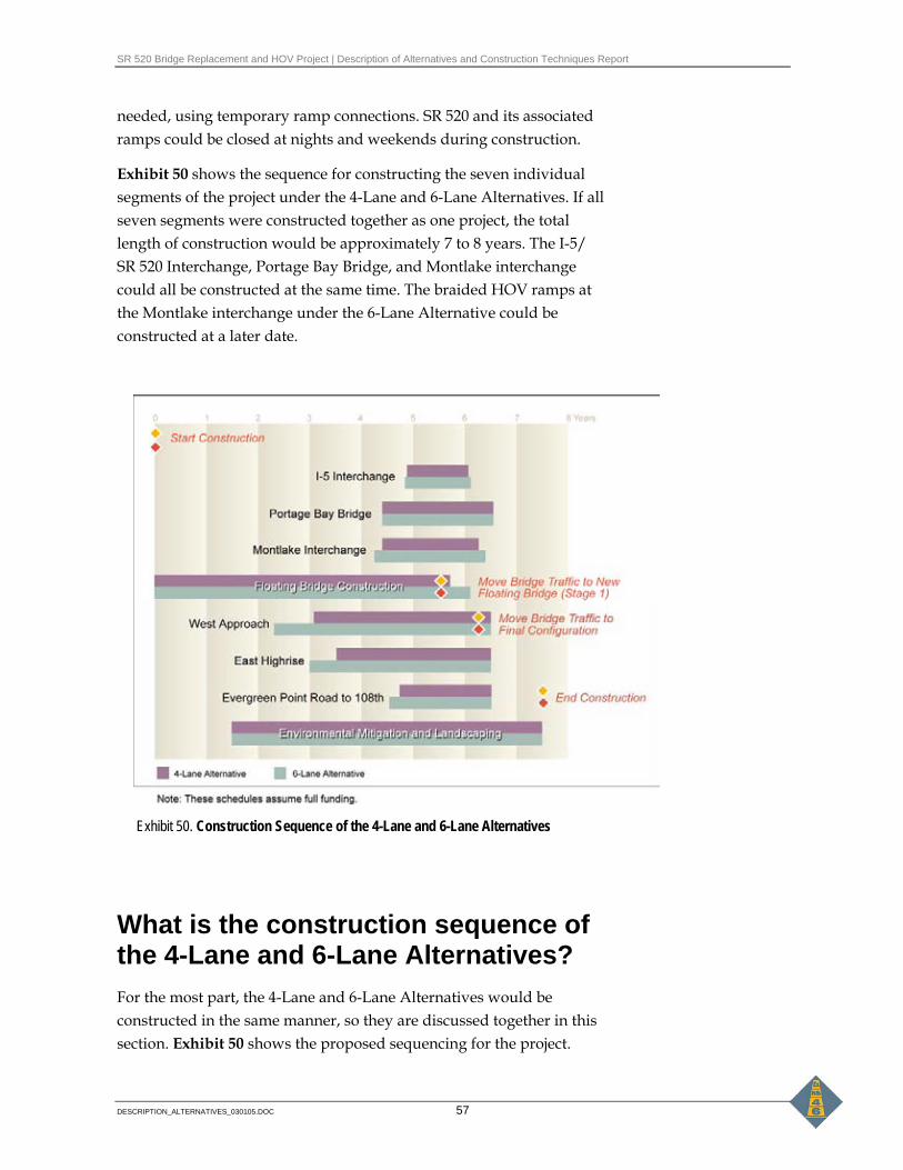
SR 520 Bridge Replacement and HOV Project | Description of Alternatives and Construction Techniques Report
DESCRIPTION_ALTERNATIVES_030105.DOC 57
needed, using temporary ramp connections. SR 520 and its associated ramps could be closed at nights and weekends during construction.
Exhibit 50 shows the sequence for constructing the seven individual segments of the project under the 4-Lane and 6-Lane Alternatives. If all seven segments were constructed together as one project, the total length of construction would be approximately 7 to 8 years. The I-5/ SR 520 Interchange, Portage Bay Bridge, and Montlake interchange could all be constructed at the same time. The braided HOV ramps at the Montlake interchange under the 6-Lane Alternative could be constructed at a later date.
What is the construction sequence of the 4-Lane and 6-Lane Alternatives? For the most part, the 4-Lane and 6-Lane Alternatives would be constructed in the same manner, so they are discussed together in this section. Exhibit 50 shows the proposed sequencing for the project.
Exhibit 50. Construction Sequence of the 4-Lane and 6-Lane Alternatives

SR 520 Bridge Replacement and HOV Project | Description of Alternatives and Construction Techniques Report
DESCRIPTION_ALTERNATIVES_030105.DOC 58
Differences between the 4-Lane and 6-Lane Alternatives are identified where appropriate.
Bridges over SR 520 Existing bridges over SR 520 would be reconstructed to make room for a wider SR 520 roadway. At Delmar Drive East, a detour would be provided during demolition of the existing bridge and construction of the new bridge. At 10th Avenue East, Evergreen Point Road, 84th Avenue Northeast, and 92nd Avenue Northeast, the detours would consist of new bridges in temporary locations across SR 520 to carry traffic during demolition and reconstruction of the old bridge. The new bridges would be moved into place after demolition of the old bridges and would become the permanent new bridges over SR 520.
I-5/SR 520 Interchange Construction at the I-5/SR 520 interchange would begin with construction of the Delmar Drive East and 10th Avenue East bridges over SR 520.
For Delmar Drive East, the existing SR 520 roadway would be widened to construct the structure abutments. Delmar Drive East would be closed and a detour provided. The existing Delmar Drive East bridge over SR 520 would be demolished and removed. The new bridge would then be constructed and Delmar Drive East would be reopened to traffic.
For 10th Avenue East, the existing SR 520 roadway would be widened to construct the foundation of the new bridge at its temporary location. New retaining walls north and south of SR 520 would be built. The new 10th Avenue East bridge over SR 520 would then be built in its temporary location beside the existing bridge. Traffic would shift to the new 10th Avenue East bridge over SR 520. The existing 10th Avenue East bridge would be demolished and removed. After completion of the new bridge foundation, 10th Avenue East would be temporarily closed to traffic, moved to its final location, and then reopened to traffic.
The next stage would entail widening the outside areas of SR 520. The following is a sequence of construction activities:
• Widen the ramp temporarily on the left side of the existing northbound I-5 to eastbound SR 520 ramp.

SR 520 Bridge Replacement and HOV Project | Description of Alternatives and Construction Techniques Report
DESCRIPTION_ALTERNATIVES_030105.DOC 59
• Shift the northbound I-5 to eastbound SR 520 ramp traffic to the outside (left) onto the temporarily widened ramp.
• Construct the northbound I-5 to eastbound SR 520 ramp from the existing ramp on I-5 to the west end of the existing Portage Bay Bridge.
• Shift the westbound SR 520 to northbound I-5 ramp traffic to the right side of the ramp and add temporary pavement on the left side for a temporary traffic lane.
• Shift the westbound SR 520 to northbound I-5 ramp traffic to the left side onto temporary pavement.
• Close the existing westbound SR 520 to Harvard Avenue ramp.
• Construct the westbound SR 520 to Harvard Avenue ramp.
• Construct the westbound SR 520 to northbound I-5 ramp and lid wall (for the 6-Lane Alternative) on the right side of the ramp.
• Construct the retaining wall between the westbound SR 520 to northbound I-5 ramp and the westbound SR 520 to Harvard Avenue ramp.
• Shift the westbound SR 520 to northbound I-5 ramp traffic to the right side to complete the improvements.
• Complete the westbound SR 520 to northbound I-5 ramp on the left side of the ramp.
• Construct the temporary connection from the existing Portage Bay Bridge to the westbound SR 520 to northbound I-5 ramp, and the westbound SR 520 to Harvard Avenue ramp.
• Restore traffic to the westbound SR 520 to northbound I-5, northbound I-5 to eastbound SR 520, and westbound SR 520 to Harvard Avenue ramps.
The next stage would entail constructing the remaining ramps. The following is a sequence of construction activities:
• Shift the westbound SR 520 to southbound I-5 traffic to the north, narrowing the two existing lanes lanes.
• Construct the southbound I-5 to eastbound SR 520 tunnel south of the westbound SR 520 to southbound I-5 lanes.

SR 520 Bridge Replacement and HOV Project | Description of Alternatives and Construction Techniques Report
DESCRIPTION_ALTERNATIVES_030105.DOC 60
• Construct the south portion of westbound SR 520 to the southbound I-5 lanes.
• Shift the westbound SR 520 to the southbound I-5 traffic to the south, providing two lanes.
• Construct the southbound I-5 to eastbound SR 520 tunnel north of the westbound SR 520 to southbound I-5 lanes.
• Construct the north portion of the westbound SR 520 to southbound I-5 lanes.
• Reduce the I-5 express lanes to three lanes.
• Construct the reversible HOV structure across I-5.
For the 6-Lane Alternative, the 10th and Delmar lid would be built in coordination with construction of the other I-5/SR 520 improvements described above. For example, the northern portions of the 10th and Delmar lid would be built when the north side of SR 520 is being widened and traffic has shifted south. The lid would not be finished until after all other I-5/SR 520 interchange and Portage Bay Bridge improvements are completed.
Portage Bay Bridge A work bridge would be constructed along the north side of the existing bridge, between Boyer Avenue on the west and the NOAA parking lot on the east. The north (westbound) lanes of the new bridge would be constructed from the work bridge. All traffic would stay on the existing Portage Bay Bridge until the north portion of the new bridge is built. Once completed, traffic would be shifted to the north portion of the new bridge, and the existing westbound lanes would be demolished. This shift would be coordinated with construction of the new the I-5/SR 520 and Montlake interchanges.
Next, for the 4-Lane Alternative only, the two middle lanes of the bridge and a temporary SR 520 East to Montlake Boulevard ramp would be constructed from the work bridge. Traffic would be shifted from the existing eastbound lanes to the new middle section. The work bridge would be dismantled and reinstalled on the south side of the existing bridge. The remainder of the existing bridge would be removed.

SR 520 Bridge Replacement and HOV Project | Description of Alternatives and Construction Techniques Report
DESCRIPTION_ALTERNATIVES_030105.DOC 61
The new southern section of the Portage Bay Bridge and new permanent SR 520 East to Montlake Boulevard ramp structure would be constructed from the work bridge. Traffic would be shifted as needed to complete the bridge and dismantle the temporary structures.
Construction staging for the Portage Bay Bridge under the 6-Lane Alternative would differ from the 4-Lane Alternative because the existing structure could be dismantled in one step, which would require less shifting of traffic. A temporary work bridge would be constructed along the north side of the existing bridge. The north half of the new bridge would be constructed from the work bridge, which would be wide enough to temporarily carry two lanes of traffic in each direction. A temporary SR 520 East to Montlake Boulevard structure would be constructed and all SR 520 traffic would be shifted to the new half of the bridge. The work bridge would be shifted to the south side of the bridge, and the existing bridge would be dismantled.
The south half of the new Portage Bay Bridge would be constructed up to the temporary Montlake Boulevard ramp. After construction of the permanent SR 520 East to Montlake Boulevard ramp, traffic would be shifted to the new ramp and the remaining south half of the Portage Bay Bridge would be completed. The temporary ramp and work bridge would be removed.
Montlake Interchange Construction of the Montlake interchange would begin by constructing the temporary SR 520 westbound on- and off-ramps and shifting traffic to those temporary ramps. Next, the roadway on the north (westbound) side of SR 520 at Montlake would be widened. The new bridge for Montlake Boulevard over SR 520 would be constructed at a temporary location. The 24th Avenue East bridge over SR 520 (which connects to MOHAI) would be closed and the new 24th Avenue East bridge constructed. Montlake Boulevard bridge traffic would be shifted to the new bridge at its temporary location and the existing structure would be removed. Montlake Boulevard would be closed temporarily to move the new bridge to its final location.
After that, Montlake Boulevard and the 24th Avenue East bridges over SR 520 would be opened to traffic. The permanent ramps to Montlake Boulevard would then be constructed and opened to traffic. Construction of westbound SR 520 under Montlake Boulevard would be completed.

SR 520 Bridge Replacement and HOV Project | Description of Alternatives and Construction Techniques Report
DESCRIPTION_ALTERNATIVES_030105.DOC 62
Under the 6-Lane Alternative, construction of the north half of the Montlake Boulevard lid would begin. Traffic would be shifted to the completed north half of SR 520 (to be coordinated with the Portage Bay Bridge and floating bridge construction). Finally, construction of the Montlake Boulevard lid would be completed.
The last stage of construction at the Montlake interchange would begin with all traffic being shifted to the westbound SR 520 lanes. Next, the interim eastbound Montlake loop ramp would be constructed, followed by the eastbound SR 520 HOV braided ramps. Then, all traffic would be shifted to the final configuration. Finally, the westbound HOV braided ramps would be constructed.
West Approach to Evergreen Point Bridge For both alternatives, a detour bridge would be built to carry SR 520 traffic during construction. Once traffic shifts to the detour bridge, the existing SR 520 structure would be used as a work bridge for construction of the new SR 520 west approach.
The first stage would be to build the detour bridge. The 60-foot-wide detour bridge would be constructed on the south side of the existing SR 520 structure. The Lake Washington Boulevard ramps would be closed throughout construction. The detour bridge would be tied to the existing SR 520 structure. Traffic would shift over to the new detour bridge after it is constructed and secured.
The next stage would be to construct the finger piers and new approaches, which would be constructed from the existing SR 520 structure. Construction of the new SR 520 west approach would be coordinated with construction of the floating section of the bridge. Once complete, traffic would shift to the new structure and floating bridge. The existing SR 520 structure would then be removed using the detour bridge as a work bridge. After most portions of the Lake Washington Boulevard ramps are completed, the detour bridge and finger piers would be removed. The last remaining portions of the Lake Washington Boulevard ramps that connect to SR 520 would then be built, completing construction of the west approach.
Floating Section of Evergreen Point Bridge The new floating bridge would be constructed to the north of the existing floating bridge. The existing midlake navigation channel would be kept operational until the new bridge is in place. Traffic would

SR 520 Bridge Replacement and HOV Project | Description of Alternatives and Construction Techniques Report
DESCRIPTION_ALTERNATIVES_030105.DOC 63
remain on the existing structure until the west approach structures, floating bridge, and the north half of the east approach structures are completed.
Anchors, pontoons, and the superstructures for the floating bridge would be constructed offsite at a graving dock located outside of Lake Washington.
Construction would begin with installation of the anchors on the bottom of Lake Washington. The pontoons would be floated into Lake Washington and connected to the anchors with cables. The existing midlake navigation channel would be kept open during this time. The pontoons would be assembled on the lake. Assembly would include connection of the superstructures between adjacent pontoons, electrical system installation, barrier construction, and final deck construction. The midlake navigation channel would then be closed and the floating section would be connected to the new west and east approach structures.
Once traffic is shifted onto the new Evergreen Point Bridge, the existing pontoons would be disconnected from the anchors and adjacent pontoons and the pontoons would be floated offsite. The anchors would be left in the lake bottom.
East Highrise of Evergreen Point Bridge Traffic would remain on the existing east approach structure until completion of the west approach structures, floating bridge, and north half of east approach structures.
The north half of the east highrise would be constructed first, followed by the north half of the transition span between the floating section of the Evergreen Point Bridge and the east highrise structure.
After completion of the north half of the east highrise structure, traffic would shift to the north half of that new structure. The existing highrise would be removed to allow room to build the south half of the east highrise. The south half of the transition span between the floating section and the east highrise structure would then be constructed.
Evergreen Point Road Traffic would remain on SR 520 during construction. Existing pavement would be widened to allow for lane shifts while constructing abutments, columns, and/or lid walls. The highway would be widened
SR 520 Bridge Replacement and HOV Project | Description of Alternatives and Construction Techniques Report
DESCRIPTION_ALTERNATIVES_030105.DOC 64
predominantly to the north; areas outside of the existing roadway would be widened first. After widening of the roadway, the new bridge that carries Evergreen Point Road over SR 520 would be built next to the existing bridge. Traffic would shift to the new Evergreen Point Road bridge and the existing bridge would be demolished and removed.
Once the new Evergreen Point Road bridge is completed, Evergreen Point Road would be temporarily closed while the new bridge is moved to its final location. Because there is no other access for Evergreen Point Road, it would remain open for emergency vehicles. Room for at least one emergency vehicle to cross the bridge will be available throughout the time that the bridge is moved; construction crews will coordinate with emergency service providers prior to the temporary closure. Evergreen Point Road would then be reopened to traffic.
For the 4-Lane Alternative, only the SR 520 roadway would remain to be built. For the 6-Lane Alternative, however, the SR 520 roadway and Evergreen Point lid would still remain to be constructed. The north section of the roadway/or lid would be built first. Traffic would shift from both directions to the north section of SR 520 lanes at Evergreen Point Road. Next, the middle section of the roadway/lid at Evergreen Point Road would be built. Finally, the south section of roadway/lid at Evergreen Point Road would be built at the same time that the east highrise is being constructed. When completed, eastbound traffic would shift back from the westbound lanes to the new eastbound lanes.
84th Avenue Northeast and 92nd Avenue Northeast At 84th Avenue Northeast and 92nd Avenue Northeast, SR 520 would be constructed in the same way as described for Evergreen Point Road.
First, areas outside of the existing SR 520 roadway would be widened equally on the north and south sides. Next, temporary ramps and bridges would be constructed. Existing pavement for lane shifts would be removed to allow for construction of abutments, columns, and/or lid walls.
Next, for the 6-Lane Alternative, the north section of both lids would be constructed. For both alternatives, new bridges over SR 520 at 84th Avenue Northeast and 92nd Avenue Northeast would be built next to the existing bridges.
SR 520 Bridge Replacement and HOV Project | Description of Alternatives and Construction Techniques Report
DESCRIPTION_ALTERNATIVES_030105.DOC 65
Traffic would shift to the new bridges, and the existing 84th Avenue Northeast and 92nd Avenue Northeast bridges would be demolished and removed.
At this time, the new bridges would be temporarily closed to traffic and moved to their final locations. Because there is no other access for 84th Avenue Northeast, the new bridge would remain open for emergency vehicles. Enough room to accommodate at least one emergency vehicle will be available during the move; construction crews will coordinate with emergency service providers prior to closure. After the bridges are moved into place, the roadways would be reopened to traffic.
For the 4-Lane Alternative, only the SR 520 roadway would remain to be built. For the 6-Lane Alternative, the SR 520 roadway and 84th Avenue Northeast and 92nd Avenue Northeast lids would remain to be built. Eastbound SR 520 traffic would be separated from the westbound lanes to the outside of SR 520, between 92nd Avenue Northeast and until just east of Evergreen Point Road. For the 6-Lane Alternative, the middle sections of the lids would then be built. Next, for both alternatives, the roadway construction in the median from Evergreen Point Road to 92nd Avenue Northeast would be completed. Finally, for the 6-Lane Alternative, the south section of the lids would then be constructed.
Bellevue Way Temporary ramps and the new Bellevue Way bridge over SR 520 at its temporary location would be constructed first. The existing SR 520 pavement would be widened to allow for lane shifts during construction of abutments, columns, and walls.
Once the new Bellevue Way bridge is built, traffic would shift to a temporary location. The existing Bellevue Way bridge over SR 520 would then be demolished and removed.
Bellevue Way would be temporarily closed when the new bridge is moved to its final location. After the move is complete, Bellevue Way would be reopened to traffic. Finally, the SR 520 roadway would be constructed.
SR 520 Bridge Replacement and HOV Project | Description of Alternatives and Construction Techniques Report
DESCRIPTION_ALTERNATIVES_030105.DOC 66
Auxiliary Lane between I-405 and 124th Avenue Northeast To construct the auxiliary lane between I-405 and 124th Avenue Northeast, existing shoulder widths on eastbound SR 520 would be reduced so that traffic could be moved to one side. The new auxiliary lane would then be constructed. After the lane is added, traffic would be shifted back and shoulder widths would be restored.
SR 520 Bridge Replacement and HOV Project | Description of Alternatives and Construction Techniques Report
DESCRIPTION_ALTERNATIVES_030105.DOC 67
References Baker, Brent. Parsons Brinckerhoff, Seattle, Washington. September 24, 2003—Memorandum regarding Proposed 2003 PM Peak and Off-Peak Toll Rates for the SR 520 Bridge Replacement and HOV Project EIS Modeling.
CH2M HILL and Parametrix. 2004. Preliminary Stormwater Management Report. Prepared for the Washington State Department of Transportation Urban Corridors Office and Sound Transit, Seattle, Washington.
Parametrix. 2004. SR 520 Bridge Replacement and HOV Project, Flexible Transportation Plan. Parametrix, Bellevue, Washington.
Parametrix and CH2M HILL. 2004. SR 520 8-Lane Alternative I-5 Options Report. Parametrix, Bellevue, Washington, and CH2M HILL, Bellevue, Washington.
WSDOT. 2004. Highway Runoff Manual. Publication M31-16. Washington State Department of Transportation. March 2004.
WSDOT and Sound Transit. 2000. First-Level Screening Results-Technical Steering Committee Review Draft with Comments. Washington State Department of Transportation and Sound Transit. October.
WSDOT and Sound Transit. 2001a. Highway Modal Evaluation-Transportation, Environmental, and Cost Findings. Washington State Department of Transportation and Sound Transit. April
WSDOT and Sound Transit. 2001b. High Capacity Transit Modal Evaluation—Transportation, Environmental, and Cost Findings. Washington State Department of Transportation and Sound Transit. April.
WSDOT and Sound Transit. 2001c. Multi-Modal Alternatives Evaluation Report. Washington State Department of Transportation and Sound Transit. June.
WSDOT and Sound Transit. 2002a. Accommodating High Capacity Transit in the SR 520 Corridor. Washington State Department of Transportation and Sound Transit. August.
WSDOT and Sound Transit. 2002b. Summary of HCT Screening Process - Evaluation and Recommendations. Washington State Department of Transportation and Sound Transit. December.


Exhibits


Attachment 1
Scale Drawings of Bridge Profiles


180171.ag.a5.02 ALT_Ex01_PortageBayAndMontlake_28feb05
Exhibit 1. SR 520 ProfilePortage Bay and Montlake SR 520 Bridge Replacement and HOV Project
Proposed Structure
Existing Structure
Existing Ground
Water Elevation
Notes:
Profile shown is for 6-Lane Alternative; the 4-Lane Alternative profile would be similar.
Heights shown are approximate measured to bottom of structure.


180171.ag.a5.02 ALT_Ex03_LkWashingtonEHighrise_28feb05
Exhibit 3. SR 520 ProfileLake Washington and East Highrise SR 520 Bridge Replacement and HOV Project
Proposed Structure
Existing Structure
Existing Ground
Water Elevation
Notes:
Profile shown is for 6-Lane Alternative; the 4-Lane Alternative profile would be similar.
Heights shown are approximate measured to bottom of structure.

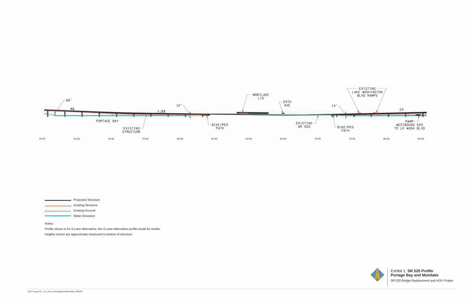
180171.ag.a5.02 ALT_Ex01_PortageBayAndMontlake_28feb05
Exhibit 1. SR 520 ProfilePortage Bay and Montlake SR 520 Bridge Replacement and HOV Project
Proposed Structure
Existing Structure
Existing Ground
Water Elevation
Notes:
Profile shown is for 6-Lane Alternative; the 4-Lane Alternative profile would be similar.
Heights shown are approximate measured to bottom of structure.


180171.ag.a5.02 ALT_Ex02_Arboretum WApproach_28feb05
Exhibit 2. SR 520 ProfileArboretum/West Approach Structure SR 520 Bridge Replacement and HOV Project
Proposed Structure
Existing Structure
Existing Ground
Water Elevation
Notes:
Profile shown is for 6-Lane Alternative; the 4-Lane Alternative profile would be similar.
Heights shown are approximate measured to bottom of structure.

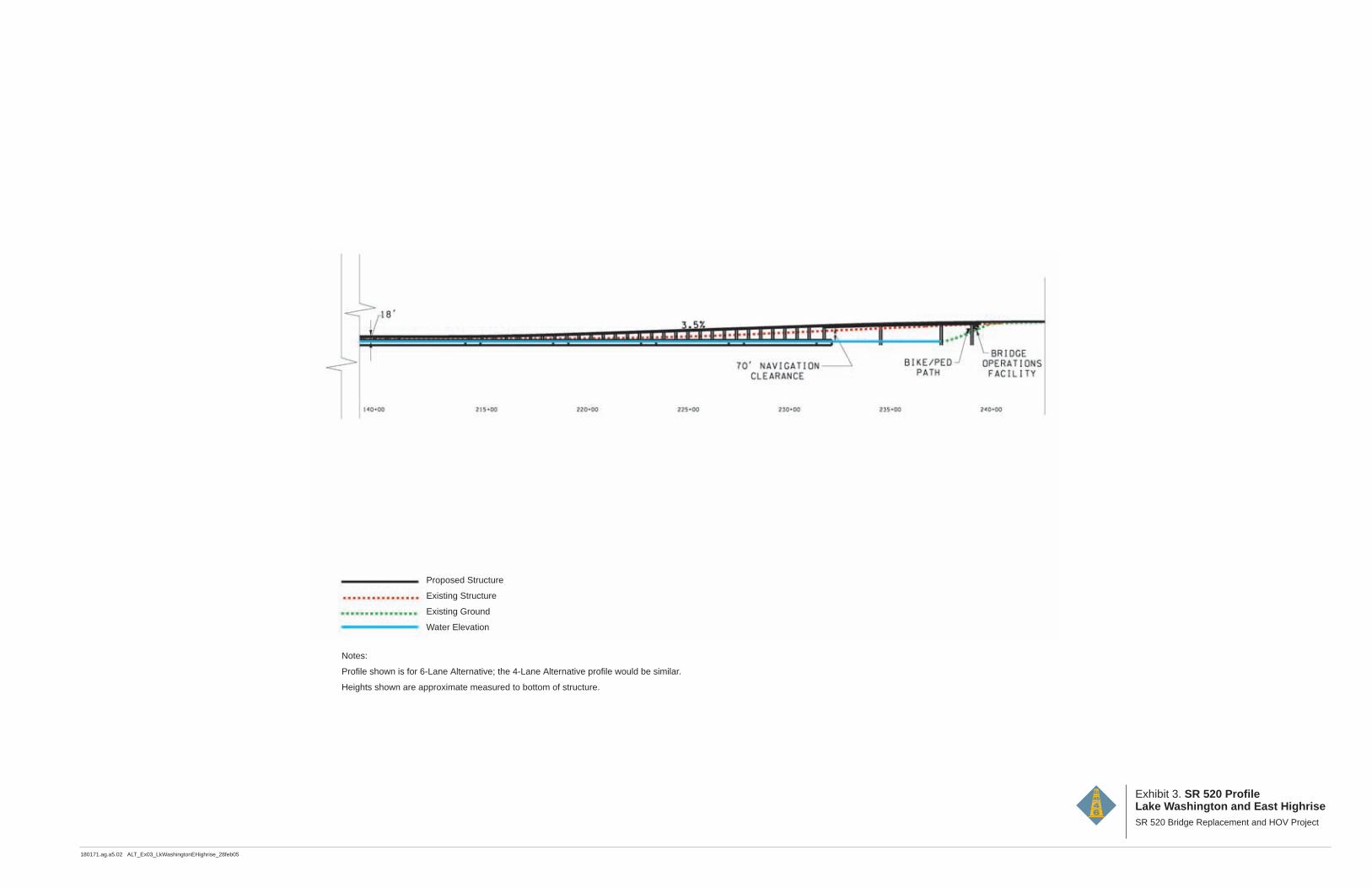
180171.ag.a5.02 ALT_Ex03_LkWashingtonEHighrise_28feb05
Exhibit 3. SR 520 ProfileLake Washington and East Highrise SR 520 Bridge Replacement and HOV Project
Proposed Structure
Existing Structure
Existing Ground
Water Elevation
Notes:
Profile shown is for 6-Lane Alternative; the 4-Lane Alternative profile would be similar.
Heights shown are approximate measured to bottom of structure.

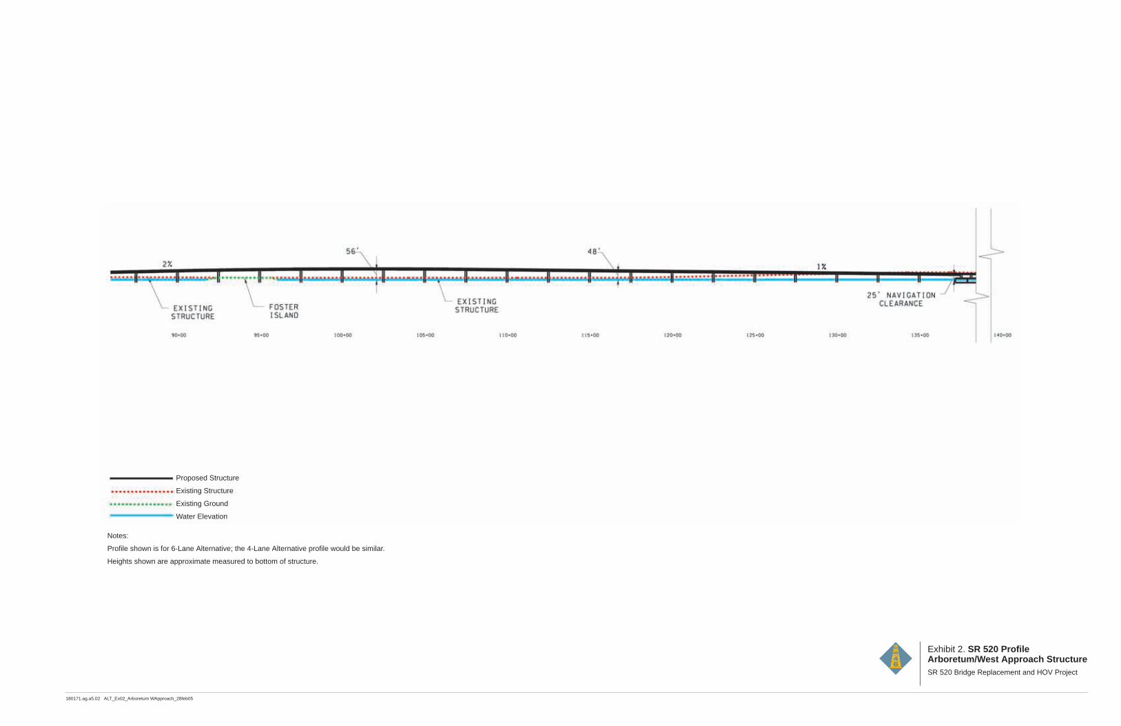
180171.ag.a5.02 ALT_Ex02_Arboretum WApproach_28feb05
Exhibit 2. SR 520 ProfileArboretum/West Approach Structure SR 520 Bridge Replacement and HOV Project
Proposed Structure
Existing Structure
Existing Ground
Water Elevation
Notes:
Profile shown is for 6-Lane Alternative; the 4-Lane Alternative profile would be similar.
Heights shown are approximate measured to bottom of structure.