sps series medium power dc power supplies - · pdf filem470008-01 rev a sps series medium...
TRANSCRIPT

M470008-01 Rev A www.programmablepower.com
SPS Series
Medium Power DC Power Supplies
Operation Manual


i
About AMETEK
AMETEK Programmable Power, Inc., a Division of AMETEK, Inc., is a global leader in the design and manufacture of precision, programmable power supplies for R&D, test and measurement, process control, power bus simulation and power conditioning applications across diverse industrial segments. From bench top supplies to rack-mounted industrial power subsystems, AMETEK Programmable Power is the proud manufacturer of Elgar, Sorensen, California Instruments, AMREL and Power Ten brand power supplies.
AMETEK, Inc. is a leading global manufacturer of electronic instruments and electromechanical devices with annualized sales of $2.5 billion. The Company has over 11,000 colleagues working at more than 80 manufacturing facilities and more than 80 sales and service centers in the United States and around the world.
Trademarks
AMETEK is a registered trademark of AMETEK, Inc. Other trademarks, registered trademarks, and product names are the property of their respective owners and are used herein for identification purposes only.
Notice of Copyright
SPS K Series DC Power Supplies Operation Manual © October 2010 AMETEK Programmable Power, Inc. All rights reserved.
Exclusion for Documentation
UNLESS SPECIFICALLY AGREED TO IN WRITING, AMETEK PROGRAMMABLE POWER, INC. (“AMETEK”):
(a) MAKES NO WARRANTY AS TO THE ACCURACY, SUFFICIENCY OR SUITABILITY OF ANY TECHNICAL OR OTHER INFORMATION PROVIDED IN ITS MANUALS OR OTHER DOCUMENTATION.
(b) ASSUMES NO RESPONSIBILITY OR LIABILITY FOR LOSSES, DAMAGES, COSTS OR EXPENSES, WHETHER SPECIAL, DIRECT, INDIRECT, CONSEQUENTIAL OR INCIDENTAL, WHICH MIGHT ARISE OUT OF THE USE OF SUCH INFORMATION. THE USE OF ANY SUCH INFORMATION WILL BE ENTIRELY AT THE USER’S RISK, AND
(c) REMINDS YOU THAT IF THIS MANUAL IS IN ANY LANGUAGE OTHER THAN ENGLISH, ALTHOUGH STEPS HAVE BEEN TAKEN TO MAINTAIN THE ACCURACY OF THE TRANSLATION, THE ACCURACY CANNOT BE GUARANTEED. APPROVED AMETEK CONTENT IS CONTAINED WITH THE ENGLISH LANGUAGE VERSION, WHICH IS POSTED AT WWW.PROGRAMMABLEPOWER.COM.
Date and Revision
October 2010 Revision A
Part Number
M470008-01
Contact Information
Telephone: 800 733 5427 (toll free in North America) 858 450 0085 (direct) Fax: 858 458 0267 Email: [email protected] [email protected] Web: www.programmablepower.com

ii
This page intentionally left blank.

iii
Important Safety Instructions Before applying power to the system, verify that your product is configured properly for your particular application.
WARNING
Hazardous voltages may be present when covers are removed. Qualified personnel must use extreme caution when servicing this equipment. Circuit boards, test points, and output voltages also may be floating above (below) chassis ground.
WARNING
The equipment used contains ESD sensitive ports. When installing equipment, follow ESD Safety Procedures. Electrostatic discharges might cause damage to the equipment.
Only qualified personnel who deal with attendant hazards in power supplies, are allowed to perform installation and servicing.
Ensure that the AC power line ground is connected properly to the Power Rack input connector or chassis. Similarly, other power ground lines including those to application and maintenance equipment must be grounded properly for both personnel and equipment safety.
Always ensure that facility AC input power is de-energized prior to connecting or disconnecting any cable.
In normal operation, the operator does not have access to hazardous voltages within the chassis. However, depending on the user’s application configuration, HIGH VOLTAGES HAZARDOUS TO HUMAN SAFETY may be normally generated on the output terminals. The customer/user must ensure that the output power lines are labeled properly as to the safety hazards and that any inadvertent contact with hazardous voltages is eliminated.
Guard against risks of electrical shock during open cover checks by not touching any portion of the electrical circuits. Even when power is off, capacitors may retain an electrical charge. Use safety glasses during open cover checks to avoid personal injury by any sudden component failure.
Neither AMETEK Programmable Power Inc., San Diego, California, USA, nor any of the subsidiary sales organizations can accept any responsibility for personnel, material or inconsequential injury, loss or damage that results from improper use of the equipment and accessories.
SAFETY SYMBOLS

iv
This page intentionally left blank.

v
Product Family: SPS K Series DC Power Supplies
Warranty Period: Three Years
WARRANTY TERMS
AMETEK Programmable Power, Inc. (“AMETEK”), provides this written warranty covering the Product stated above, and if the Buyer discovers and notifies AMETEK in writing of any defect in material or workmanship within the applicable warranty period stated above, then AMETEK may, at its option: repair or replace the Product; or issue a credit note for the defective Product; or provide the Buyer with replacement parts for the Product.
The Buyer will, at its expense, return the defective Product or parts thereof to AMETEK in accordance with the return procedure specified below. AMETEK will, at its expense, deliver the repaired or replaced Product or parts to the Buyer. Any warranty of AMETEK will not apply if the Buyer is in default under the Purchase Order Agreement or where the Product or any part thereof:
• is damaged by misuse, accident, negligence or failure to maintain the same as specified or required by AMETEK;
• is damaged by modifications, alterations or attachments thereto which are not authorized by AMETEK;
• is installed or operated contrary to the instructions of AMETEK;
• is opened, modified or disassembled in any way without AMETEK’s consent; or
• is used in combination with items, articles or materials not authorized by AMETEK.
The Buyer may not assert any claim that the Products are not in conformity with any warranty until the Buyer has made all payments to AMETEK provided for in the Purchase Order Agreement.
PRODUCT RETURN PROCEDURE
1. Request a Return Material Authorization (RMA) number from the repair facility (must be done in the country in which it was purchased):
• In the USA, contact the AMETEK Repair Department prior to the return of the product to AMETEK for repair:
Telephone: 800-733-5427, ext. 2295 or ext. 2463 (toll free North America) 858-450-0085, ext. 2295 or ext. 2463 (direct)
• Outside the United States, contact the nearest Authorized Service Center (ASC). A full listing can be found either through your local distributor or our website, www.programmablepower.com, by clicking Support and going to the Service Centers tab.
2. When requesting an RMA, have the following information ready:
• Model number
• Serial number
• Description of the problem
NOTE: Unauthorized returns will not be accepted and will be returned at the shipper’s expense.
NOTE: A returned product found upon inspection by AMETEK, to be in specification is subject to an evaluation fee and applicable freight charges.

vi
This page intentionally left blank.

1 | P a g e
Table of Contents
I. FEATURES AND SPECIFICATIONS 2 II: INSTALLATION 16 III: LOCAL OPERATION 25 IV. REMOTE OPERATION 43 V. CALIBRATION 79

2 | P a g e
I. FEATURES AND SPECIFICATIONS INTRODUCTION The AMREL Medium Power SPS Series Switching Power Supply provides a complete solution offering to your power supply needs. The Medium Power SPS series is rated for 5kW, 10kW, and 15kW in a 3U package and 20kW, 25kW, and 30kW in a 6U package, with a wide selection of models. The SPS is a general purpose power supply designed for research & design validation, production & process control, laboratory applications, as well as a recommended dc power instrument standard for automatic test (ATE) systems. The wide range of output ratings, ease of operation, fast response and low PARD combined with excellent load and line regulation are essential to a lab or R&D environment. In addition, the SPS provides stable and accurate voltage and current regulation for electrochemical applications, such as battery charging, ultracapacitor and fuel cell testing. Voltage and Current auto-sequencing (VLIST & I LIST), 16-bit digital programming and resolution, extensive protection modes (OVP, OCP and OTP), and in-rack closed case calibration ensure reliability and maximize return on investment, perfect for burn-in applications, compliance testing and component/product testing & validation. Local front panel controls are standard with keypad and encoder, which allows increased controllability and ease-of-use. The 19” rack-mountable medium-power SPS comes with Standard Commands for Programmable Instrument (SCPI) commands, LabVIEW & LabWindows drivers, and a multitude of computer interfaces, GPIB, RS-232, USB and Ethernet, ideal for system integrators and ATE systems used in a diverse application portfolio. The flexible external analog programming and monitoring provide precision control for production facilities using PLC or analog controllers, or precision process control applications, i.e. ion beam steering or plating. The AMREL Medium Power SPS is designed for quality, reliability, flexibility and performance to meet the needs of bench-top, laboratory/research, process control and production, burn-in, and ATE system applications. FEATURES AND OPTIONS
• High Power Density: Up to 15 kW in a 3U / 30 kW in a 6U chassis • Fast Load Transient Response: Protection from undesired voltage excursions • Low RMS and P-P Noise: Suitable for the most sensitive applications • Parallel up to 150 kW: Expandable as your requirement grows • Modular Design: Upgradeable for the ultimate in investment protection. • 20X2 VFD displays easy-to-read and accurate constant voltage and constant current settings and values • Digital OVP, OCP, ILIST and VLIST display for easy function recognition • Real-time encoder provides precise and on-the-fly voltage and current control • Automatic constant voltage and constant current mode crossover • Multi-functional front panel keypad for high resolution and precise digital OVP, OCP, ILIST, VLIST,
current and voltage control • Remote programming control with standardized SCPI commands for advanced and integrated ATE Testing • Embedded Ethernet and USB interface option without the need for interface converters • Remote Shutdown (S/D) and Interlock provides various external output shutdown capability – in case of hazardous faults • External Fault (FLT) and Remote Shutdown (S/D) signal for scaled remote ATE system integration • Remote/Front Panel Lockout to ensure protection for remote ATE systems • In-field GPIB, RS232, USB, Ethernet and Firmware Upgrades to prevent down-time, satisfy new and dynamic system
applications and provide up-to-date software maintenance • 16 bit Read back and Programming DAC for high resolution and accuracy for standalone or burn-in testing without the need for
external measuring equipment • Convenient and robust automated testing - four step profiles; 32 step points for each profile • Closed-case calibration for the digital controls will minimize down-time, reduce maintenance costs, and increase Return on
Investment (ROI) • Remote Sense compensates for measurement errors due to line voltage drops • Increased control precision and convenience in external programming applications achieved through various external voltage
and current control methods. TECHNICAL SPECIFICATIONS

3 | P a g e
The following subsections provide environmental, electrical, and physical characteristics for the SPS MEDIUM POWER Series power supplies.
ENVIRONMENTAL CHARACTERISTICS
PARAMETER SPECIFICATION
TEMPERATURE COEFFICIENT 0.02%/°C of maximum output voltage rating for voltage set point. 0.03%/°C of maximum output current rating for current set point.
AMBIENT TEMPERATURES
Operating 0 to 50°C
Storage -25° to 65°C
COOLING Internal fans; vents on sides and rear. (Units may be stacked without clearance above or below).
HUMIDITY 95% maximum, non-condensing, 0 to 50°C; 45°C maximum wet-bulb temperature
ALTITUDE Operating full power available up to 5,000 feet (1,524m), derate 10% of full power for every 1,000 feet higher; non-operating to 40,000 feet (12,192m)
OZONE CONCENTRATION Recommended long-term exposure limit is 0.1 PPM (0.2 mg/m3).
ELECTRICAL CHARACTERISTICS
PARAMETER SPECIFICATION
INPUT POWER Voltage (Standard) 208/220 VAC±10% (allowed range 187-242 VAC)
Voltage (Options) 380/400 VAC±10% (allowed range 342-440 VAC) 440/480 VAC±10% (allowed range 396-528 VAC)
Frequency 47 to 63 Hz Phases 3–phase, 3–wire plus ground. Not phase rotation sensitive. Neutral not used.
Power Factor 0.9 typical for 208/220VAC input0.78 typical for 380/400VAC input0.7 typical for 440/480VAC input
Efficiency 87% typical at full load, nominal line
FRONT PANEL METER ACCURACY Voltage ±0.15% of full-scale Current ±0.4% of full-scale
LOAD REGULATION (Specified at no load to full load, nominal AC input)
Voltage 0.02% of maximum output voltage Current 0.1% of maximum output current
LINE REGULATION (Specified ±10% of nominal AC input, constant load)
Voltage 0.01% of maximum output voltage Current 0.05% of maximum output current
TRANSIENT RESPONSE A 50% step load will recover to within 0.75% of original value within 1 ms.
DOWN PROGRAMMING With no load the output will program from 100 to 10% in less than 1.5 seconds
STABILITY ±0.05% of set point after 8–hr. warm-up at fixed line, load, and temperature using remote sense
REMOTE CONTROL/MONITOR On/Off control via contact closure, 6-120 VDC or 12-240 VAC, and TTL or CMOS switch, output voltage and current monitor, OVP limit set, summary fault status
PARAMETER SPECIFICATION

4 | P a g e
FRONT PANEL AND REMOTE DIGITAL PROGRAMMING
Voltage ±0.1% of full-scale output
Current ±0.4% of full-scale output
Overvoltage Protection (OVP) ±1% of full-scale output
REMOTE DIGITAL READBACK
Voltage ±0.15% of full-scale output
Current ±0.4% of full-scale output
REMOTE ANALOG PROGRAMMING Constant Voltage ±0.25% of full-scale output for 0-5V range (±0.5% 0-10V range) Constant Current ±0.8% of full-scale output Overvoltage Protection (OVP) ±1% of full-scale output REMOTE ANALOG READBACK Voltage ±1% of full-scale output, 0-10V range Current ±1% of full-scale output, 0-10V range
RESISTIVE Constant Voltage (0-100%) 0–5 kΩ Constant Current (0-100%) 0–5 kΩ
VOLTAGE Constant Voltage (0-100%) 0–5 VDC or 0–10 VDC Constant Current (0-100%) 0–5 VDC or 0–10 VDC Overvoltage Protection (OVP) (5–110%) 0.25–5.5 VDC
REMOTE SENSING Terminals are provided to regulate output voltage at point of load. Maximum line drop 5% of rated output voltage per line for 40-100V models, 2% of rated output voltage per line for >100V models.
REMOTE ANALOG CONTROL
Input to Output Isolation
The control signal return for Non-Isolated Analog programming is connected to the negative output terminal. Under no condition should the negative terminal exceed 300V to earth ground. The maximum voltage from control signal return of the Remote Isolated Analog programming (option) to the negative output terminal is 600V.
DIMENSION 3U MODELS 6U MODELS
WIDTH 19.00 in (48.3 cm) 19.00 in (48.3 cm)
DEPTH 25.46 in (64.7 cm) 25.12 in (63.8 cm)
HEIGHT 5.25 in (13.3 cm) 10.5 in (26.7 cm)
WEIGHT (5kW) ≈ 40 lbs (18 kg) (20 KW) ≈ 120 lbs (54 kg)
(10kW) ≈ 60 lbs (27 kg) (25 kW) ≈ 140 lbs (64 kg)
(15kW) ≈ 80 lbs (36 kg) (30kW) ≈ 160 lbs (73 kg) Important Notes:
1) Specifications are subject to change without notice 2) The SPS Series power supplies are intended for indoor use only.

5 | P a g e
MODELS Amperage PARD1&2
Voltage 5 kW 10 kW 15 kW 20 kW 25 kW 30 kW RMS P–P
0-40V 0-125A 0-250A 0-375A 0-500A3 0-625A3 0-7503 20 mV 75 mV
0-60V 0-83A 0-167A 0-250A 0-333A 0-417A 0-500A 20 mV 75 mV
0-80V 0-63A 0-125A 0-188A 0-250A 0-313A 0-375A 20 mV 100 mV
0-100V 0-50A 0-100A 0-150A 0-200A 0-250A 0-300A 20 mV 100 mV
0-160V 0-31A 0-63A 0-94A 0-125A 0-156A 0-188A 25 mV 150 mV
0-200V 0-25A 0-50A 0-75A 0-100A 0-125A 0-150A 25 mV 175 mV
0-250V 0-20A 0-40A 0-60A 0-80A 0-100A 0-120A 30 mV 200 mV
0-330V 0-15A 0-30A 0-45A 0-61A 0-76A 0-91A 30 mV 200 mV
0-400V 0-12A 0-25A 0-38A 0-50A 0-63A 0-75A 40 mV 300 mV
0-600V 0-8A 0-17A 0-25A 0-33A 0-42A 0-50A 60 mV 350 mV
0-800V 0-6.2A 0-12.5A 0-18.7A 0-25A 0-31.2A 0-37.5A 80 mV 500 mV
1) P-P noise is measured across a 1uF capacitor at the end of a 6’ load cable with the supply operating at full load & at nominal input line voltage.
2) RMS noise is measured directly across the output terminals with the supply operating at full load and at nominal input line voltage.
3) Power level not available in 6U chassis. In 3U chassis, these power levels can be achieved up to 75kW by paralleling up to five power supplies. Note that paralleling will increase Ripple and Noise.

6 | P a g e
FRONT & REAR PANEL DESCRIPTION:
(1.) AC Power (2.) VFD Display
(3.) Keypad
(4.) Encoder
(5.) J1 Analog Programming Port (25P D-SUB)
(6.) & (7.) Master/Slave Input & Output Connector (9P D-SUB)
(8.) GPIB (9.) Remote Sense (10.) RS-232
(11.) LAN (12.) USB
(13.) Positive (+) DC Output Bar
(14.) Negative (-) DC Output Bar
(15.) Chassis GND
(16.) 3-ph AC Input Terminal
FIGURE 1.1 3U & 6U FRONT PANEL DESCRIPTION
FIGURE 1.2 3U REAR PANEL DESCRIPTION

7 | P a g e
FIGURE 1.3 6U REAR PANEL DESCRIPTION
(5.) GPIB (2.) Remote
Sense (6.) RS-232 (7.) LAN (1.) J1 Analog Programming
Port (25P D-SUB) (3.) & (4.) Master/Slave Input & Output Connector (9P D-SUB) (8.) USB
(9.) AC Input
(10.) DC Output
8 | P a g e
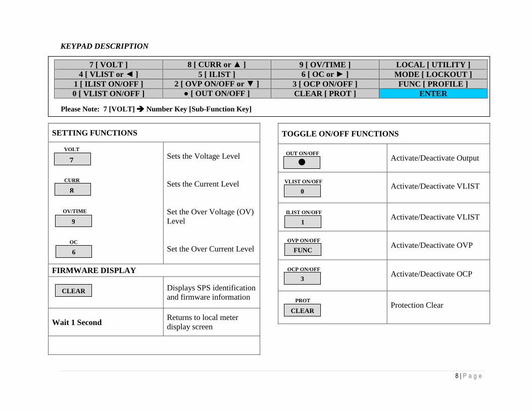
KEYPAD DESCRIPTION
SETTING FUNCTIONS
VOLT CURR OV/TIME OC
Sets the Voltage Level Sets the Current Level Set the Over Voltage (OV) Level Set the Over Current Level
FIRMWARE DISPLAY Displays SPS identification
and firmware information
Wait 1 Second
Returns to local meter display screen
TOGGLE ON/OFF FUNCTIONS
OUT ON/OFF
Activate/Deactivate Output
VLIST ON/OFF
Activate/Deactivate VLIST
ILIST ON/OFF
Activate/Deactivate VLIST
OVP ON/OFF
Activate/Deactivate OVP
OCP ON/OFF
Activate/Deactivate OCP
PROT
Protection Clear
7 [ VOLT ] 8 [ CURR or ] 9 [ OV/TIME ] LOCAL [ UTILITY ] 4 [ VLIST or ] 5 [ ILIST ] 6 [ OC or ] MODE [ LOCKOUT ]
1 [ ILIST ON/OFF ] 2 [ OVP ON/OFF or ] 3 [ OCP ON/OFF ] FUNC [ PROFILE ] 0 [ VLIST ON/OFF ] [ OUT ON/OFF ] CLEAR [ PROT ] ENTER
Please Note: 7 [VOLT] Number Key [Sub-Function Key]
7
CLEAR
0
1
FUNC
3
CLEAR
9
8
6

9 | P a g e
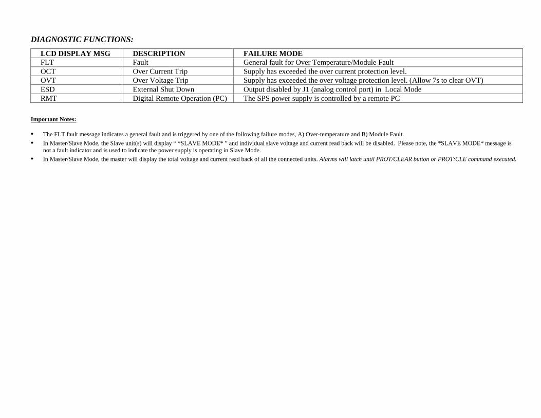
DIAGNOSTIC FUNCTIONS:
LCD DISPLAY MSG DESCRIPTION FAILURE MODE FLT Fault General fault for Over Temperature/Module Fault OCT Over Current Trip Supply has exceeded the over current protection level. OVT Over Voltage Trip Supply has exceeded the over voltage protection level. (Allow 7s to clear OVT) ESD External Shut Down Output disabled by J1 (analog control port) in Local Mode RMT Digital Remote Operation (PC) The SPS power supply is controlled by a remote PC
Important Notes:
• The FLT fault message indicates a general fault and is triggered by one of the following failure modes, A) Over-temperature and B) Module Fault.
• In Master/Slave Mode, the Slave unit(s) will display “ *SLAVE MODE* ” and individual slave voltage and current read back will be disabled. Please note, the *SLAVE MODE* message is not a fault indicator and is used to indicate the power supply is operating in Slave Mode.
• In Master/Slave Mode, the master will display the total voltage and current read back of all the connected units. Alarms will latch until PROT/CLEAR button or PROT:CLE command executed.

EXTERNAL ANALOG PROGRAMMING (J1) The Analog Control connector on the rear panel allows the unit to be configured for different operating configurations: remote current programming, remote voltage programming, current and voltage output monitoring, output enable/disable, etc. The setup and operating requirements of each configuration are provided in this section. The Medium Power SPS has the capability of providing summing of remote analog input with the set values on the front panel (or programmed values via the digital interface) for voltage, current and OVP. This capability provides a means to modulate a set value with the signal on the voltage, current and OVP analog input. If the user only desires to control the unit with the analog input, all the front panel values (V/I/OVP) or digital settings should be set to zero. Isolated Analog Control Option: The isolated Analog Control uses the same Analog Control connector (J1). This option fully isolates remote control signals and allows control of units not connected to a common ground. Control ground is isolated from output negative return, which protects against potential damage from systems with high electrical noise or large ground loop currents. Note: Some standard analog programming signals may not be available with this option. Please reference Table 1.1 External Analog Programming (J1), Signals and Functions.
This option is not intended to allow operation of the power supply at excessive voltages. Refer to Electrical Characteristics in Section I for maximum terminal voltages.
PIN NAME DESCRIPTION
1
ISO ON/OFF
Isolated remote output on/off (Electrical Chars: Zin ~ 6kΩ). Externally supplied AC/DC voltage source for on/off control. A positive (+) 12 ~ 240Vac or 6 ~ 120Vdc voltage will enable the output, i.e., turn on the output of the supply. This input control is optically isolated from the power supply circuit up to 500Vdc. Circuit return - Pin 2 (ISO RTN).
2 ISO RTN Isolated circuit return used with isolated on/off control J1-1 and J1-14.
3 REM OV
SET Remote over-voltage set (Electrical Chars: Zin ~ 20kΩ). A remote signal sets the over-voltage trip level. 0.25 ~ 5.5Vdc = 5 ~ 110%. Apply a 10.5Vdc to 13.3Vdc signal for7 seconds to reset an OVP condition. Circuit return - Pin 6 (COM).
4 VP RTN Voltage programming return (Electrical Chars: Zin ~ 10kΩ). Used with J1-9, J1-15 or J1-21 and must be referenced to Pin 6 (COM) circuit common.
5 ON/OFF Remote output on/off (Electrical Chars: Must sink ~ 1mA to enable). Switch/relay contacts or a direct short between this terminal and Pin 6 (COM) circuit common, enables the output, i.e., turns on the output of the supply.
6 COM1 Circuit common. Electrically equal to Pin 24. Same potential as the negative output terminal.
7 IMON Output current monitor (Electrical Chars: Zout ~ 100Ω). 0 ~ 10Vdc equals 0 ~ 100% rated current. Min. load resistance - 10kΩ. Circuit return - Pin 6 (COM).
8 NOT USED
FIGURE 1.4 EXTERNAL ANALOG PROGRAMMING (J1)
CAUTION

9 VP 5V Remote voltage programming using a 0 ~ 5Vdc source (Electrical Chars: Zin ~ 10kΩ). Do not exceed 13.3Vdc. Circuit return - Pin 4 or Pin 20 (VP RTN).
10 IP 5V Remote current programming using a 0 ~ 5Vdc source (Electrical Chars: Zin ~ 10kΩ). Do not exceed 13.3Vdc. Circuit return – Pin 23 or Pin 25 (IP RTN).
11 NOT USED 12
13
14 ISO
TTL/CMOS
Isolated TTL/CMOS on/off control (Electrical Chars: Zin ~ 2.2kΩ). A high state TTL/CMOS voltage enables the output, i.e., turns on the output of the supply, and a low state or open connection disables the output, i.e. turns off the output of the supply. Circuit return - Pin 2 (ISO RTN).
15 VP 10V Remote voltage programming using a 0~10Vdc source (Electrical Chars: Zin ~ 20kΩ). Do not exceed 25Vdc. Circuit return – Pin 4 or Pin 20 (VP RTN).
16 IP 10V Remote current programming using a 0~10Vdc source (Electrical Chars: Zin ~ 20kΩ). Do not exceed 25Vdc. Circuit return – Pin 23 or Pin 25 (IP RTN).
17 FAULT Fault state output (Electrical Chars: Zout ~ 100Ω). A high state (approximately +10Vdc) indicates a converter, temperature or bias supply fault, and the LED on the front panel will illuminate. Circuit return – Pin 6 (COM).
18 S/D FAULT Shutdown fault (Electrical Chars: Zout ~ 100Ω). This terminal goes to high state in the event of converter, temperature, overvoltage or bias supply fault. A 7Vdc ~ 13.3Vdc signal can be applied to this pin to shutdown the output of the unit. An 8Vdc minimum output signal is provided into a 10kΩ minimum load, in the event of an internally generated shutdown. Circuit return – Pin 6 (COM).
19 VMON Output voltage monitor (Electrical Chars: Zout ~ 100Ω). 0 ~ 10Vdc equals to 0 ~ 100% rated voltage. Minimum load resistance 10kΩ. Circuit return – Pin 6 (COM).
20 VP RTN Voltage programming return (Electrical Chars: Zin ~ 10Ω). Used with J1-9, J1-15 or J1-21 and must be referenced to Pin 6 (COM) circuit common.
21 VP RES2 1 milliamp current source for remote voltage programming using resistance (Electrical Chars: ~10.8V Compliance). 0 ~ 5kΩ resistor referenced to Circuit return Pin 23 or Pin 25 (IP RTN) will program the output voltage from 0 ~ 100%.
22 IP RES2 1 milliamp current source for remote current programming using resistance (Electrical Chars: ~10.8V Compliance). 0 ~ 5kΩ resistor referenced to Circuit return Pin 23 or Pin 25 (IP RTN) will program the output current from 0 ~ 100%.
23 IP RTN Current programming return (Electrical Chars: Zin ~ 10kΩ). Used with J1-10, J1-16 or J1-22 & must be referenced to Pin 6 (COM) circuit common.
24 COM1 Circuit common. Electrically equal to Pin 6. Same potential as the negative output terminal.
25 IP RTN Current programming return (Electrical Chars: Zin ~ 10kΩ). Used with J1-10, J1-16 or J1-22 and must be referenced to Pin 6 (COM) circuit common.
TABLE 1.1 EXTERNAL ANALOG PROGRAMMING (J1) 1) Control ground is isolated from output negative return with the isolated analog control (option). Refer to External Analog Programming (J1) in Section I. 2) Signals not available with isolated analog control (option)
If standard analog programming is used, note the programming return (J1-6 & J1-24) is at the same potential as the negative output terminal of the power supply. Observance of return connections should be made with respect to input programming signal equipment. Improper connection may result in ground loops and as a result internal power supply damage may occur. (Output current then flows to chassis by means of external connection to the J1 common (J1-6 & J1-24)
CAUTION
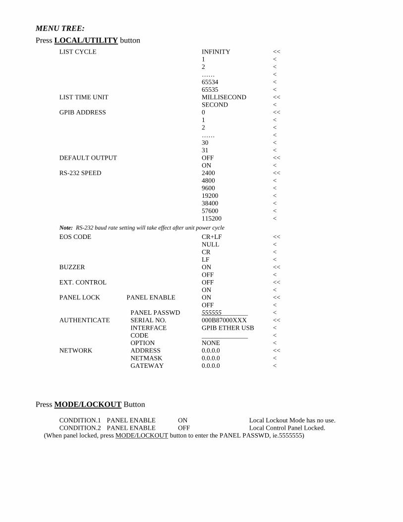
MENU TREE:
Press LOCAL/UTILITY button
LIST CYCLE INFINITY << 1 < 2 < …… < 65534 < 65535 < LIST TIME UNIT MILLISECOND << SECOND <
GPIB ADDRESS 0 << 1 < 2 < …… < 30 < 31 <
DEFAULT OUTPUT OFF << ON < RS-232 SPEED 2400 <<
4800 < 9600 < 19200 < 38400 < 57600 < 115200 <
Note: RS-232 baud rate setting will take effect after unit power cycle
EOS CODE CR+LF << NULL < CR < LF < BUZZER ON << OFF < EXT. CONTROL OFF << ON < PANEL LOCK PANEL ENABLE ON << OFF < PANEL PASSWD 555555________ < AUTHENTICATE SERIAL NO. 000B87000XXX << INTERFACE GPIB ETHER USB < CODE ______________ < OPTION NONE < NETWORK ADDRESS 0.0.0.0 << NETMASK 0.0.0.0 < GATEWAY 0.0.0.0 < Press MODE/LOCKOUT Button CONDITION.1 PANEL ENABLE ON Local Lockout Mode has no use. CONDITION.2 PANEL ENABLE OFF Local Control Panel Locked. (When panel locked, press MODE/LOCKOUT button to enter the PANEL PASSWD, ie.5555555)
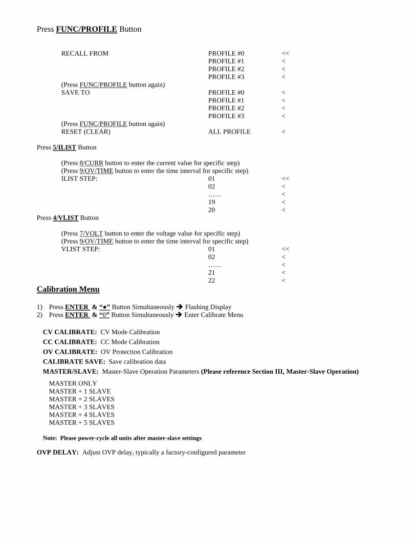
Press FUNC/PROFILE Button RECALL FROM PROFILE #0 << PROFILE #1 < PROFILE #2 < PROFILE #3 < (Press FUNC/PROFILE button again) SAVE TO PROFILE #0 < PROFILE #1 < PROFILE #2 < PROFILE #3 < (Press FUNC/PROFILE button again) RESET (CLEAR) ALL PROFILE < Press 5/ILIST Button (Press 8/CURR button to enter the current value for specific step) (Press 9/OV/TIME button to enter the time interval for specific step) ILIST STEP: 01 << 02 < …… <
19 < 20 <
Press 4/VLIST Button (Press 7/VOLT button to enter the voltage value for specific step) (Press 9/OV/TIME button to enter the time interval for specific step) VLIST STEP: 01 << 02 < …… <
21 < 22 <
Calibration Menu 1) Press ENTER & “ ” Button Simultaneously Flashing Display 2) Press ENTER & “ 0” Button Simultaneously Enter Calibrate Menu
CV CALIBRATE: CV Mode Calibration
CC CALIBRATE: CC Mode Calibration
OV CALIBRATE: OV Protection Calibration
CALIBRATE SAVE: Save calibration data
MASTER/SLAVE: Master-Slave Operation Parameters (Please reference Section III, Master-Slave Operation)
MASTER ONLY MASTER + 1 SLAVE MASTER + 2 SLAVES MASTER + 3 SLAVES MASTER + 4 SLAVES MASTER + 5 SLAVES
Note: Please power-cycle all units after master-slave settings
OVP DELAY: Adjust OVP delay, typically a factory-configured parameter

OUTPUT TERMINALS AND WIRES All models have terminal connectors on the rear panel with basic connections; a positive terminal, a negative terminal, a positive remote sense terminal, a negative remote sense terminal, and an earth ground terminal. Note: The power supply is set at the factory for local sense operation (i.e. the +S and –S terminals are connected to the "+" and "-" terminals by a jumper wire at the rear connector). When operating in remote sense mode, remove the jumpers and refer to the section on remote sense in Section III, Operation. A brief definition of remote sense is “a measurement of voltage at the load rather than at the output terminals”. Local connections are made to the "+" and "-" terminals of the power supply. Wrap and bundle wires to reduce coupling effect. In order to safely and sufficiently handle electric current, the proper wire size must be used. Select a wire size with sufficient rating to carry the current without overheating. Other factors to be taken into consideration are voltage drop and conductor temperature. OPERATING CHARACTERISTICS AND CONFIGURATIONS These sections contain information on operating characteristics and how to configure the Medium Power SPS Series. All power supplies operate in either constant voltage (CV) or constant current (CC) mode over the rated output. Their respective voltage and current operating locus are found in operating quadrants for all models. The power supply acts as a constant voltage source for comparatively large values of load resistance and as a constant current source for comparatively small values of load resistance. The automatic crossover or transition between these two modes of operations occurs at a critical stage or "crossover" value of load resistance.
(Rc = Es/Is, where Es is the front panel voltage setting and Is the front panel current setting).
Figure 1.4 is the operating quadrant (voltage vs.- current) of the Medium Power SPS series.
Currentmax
VoltagemaxCrossover
FIGURE 1.5 OPERATING QUADRANT

II: INSTALLATION INSPECTION
Inspect the shipping carton for possible damage before unpacking the unit. Carefully unpack the equipment. Save all packing materials until inspection is complete. Verify that all items listed on the packing slips have been received. Visually inspect all exterior surfaces for broken knobs, connectors, or meters. Inspect for dented or damaged exterior surfaces. External damage may be an indication of internal damage. If any damage is evident, immediately contact the carrier that delivered the unit and submit a damage report. Failure to do so could invalidate future claims. CONTENTS OF SHIPMENT
Depending on the model, configuration, and options available for your SPS Series power supply, the ship kit may include additional parts and accessories. At a minimum, the ship kit that accompanies your SPS Series power supply includes the following items: • AMREL Manual CD-ROM, Part No. M391011 containing the SPS Series DC Power Supplies Operation Manual, Part No. M391009-01 (this manual).
• Sense mating connector (Molex P/N 39-01-4031) with loose contacts (Molex P/N 39-00-0182)
• J1 mating connector (Cinch P/N DB25P or equivalent) normally shipped attached to rear panel J1
• Backshell for J1 (DB25) mating connector (Cinch P/N DCH-B-001 or equivalent)
• Bolt, lock washer, and nut for output power connections as follows: 20–30 kW: 3/8-16UNC-2B x 7/8", 4 ea for AC input and 2 ea for DC output
• Black screw, 10-32UNC-2B x ½", front panel rack fastener: 5–15 kW: 4 ea 20–30 kW: 8 ea
Note: If any of these parts are missing, please contact Customer Service at 626-443-6818 (local) or 1-800-654-9838 (toll free).

PACKAGING FOR SHIPPING OR STORAGE Follow these instructions to prepare the instrument for shipping or storage.
1- When returning the unit or sending it to the service center, attach a tag to the unit stating its model number (available at the front panel label) its serial number (available at the rear panel label) and the RMA number. Give the date of purchase and an invoice number, if you have it, as well as a brief description of the problem.
2- For storage or shipping, repack the power supply in its original box. If the original box is not available, seal the
instrument in a plastic bag and pack it in a 200 lb. (90Kg) test corrugated cardboard carton large enough allow 3 inches (76.2mm) of cushioning material to surround the unit. Use a material such as foam slabs or chips or an appropriate wooden crate used.
3- Label the package as shown in Figure 2.1. 4- Mark the address of the service center and your return address carton. 5- If storing, no more than two cartons high. The storage temperature should be between -40°C to 70°C.
FIGURE 2.1 SHIPPING OR STORAGE CARTON LABEL LOCATION AND MOUNTING
To reduce the risk of fire or electrical shock, install the SPS Medium Power Series unit in a temperature and humidity controlled indoor area, free of conductive contaminants.
The unit should be provided with proper ventilation. The rear and both sides of the unit should be free of obstructions. To ensure proper airflow, a minimum 4" clearance from the rear air outlet is required. The unit should not be installed in a raised ambient temperature greater than 50°C.
This unit is intended for installation in a protected environment. No user Serviceable parts inside. Service to be performed by qualified personnel only.
Ensure that the concentration of ozone is limited to a safe value. The recommended long-term exposure limit for ozone is 0.1 PPM (0.2 mg/m3).
Please refer to Outline Drawings in Section II for mechanical drawings. RACK INSTALLATION
CAUTION
CAUTION
WARNING
CAUTION
PROGRAMMABLE DC POWER SUPPLY Model #: _______________________ Serial #: _______________________ RMA #: _______________________ FRAGILE – ELECTRONIC EQUIPMENT (PLEASE HANDLE WITH CARE)

The Medium Power SPS Series models are designed for mounting in a standard 19-inch equipment rack. If additional instrumentation is mounted in the rack, no additional clearance is required above or below units in the SPS series.
1. Support the unit by using rack mount slides or appropriate L-brackets.
Suggested parts are listed as follows:
Rack Mount Slide Kit:
5–15kW units: P/N K550212-01 20–30kW units: P/N K550213-01 2. Secure the unit in place using the screws provided. 6U CHASSIS REMOVAL FROM RACK The slides have a Front Disconnect Feature and lock at full extension. To return chassis back into rack from locked full extension, depress the flat steel spring inward (located on the slides) and push chassis back.
The 6U SPS Series unit weighs up to 160 lbs (73kg) depending on the model. A minimum three-person lift is required! To disconnect and remove chassis from rack, depress the flat steel spring inward (located on the slides) and pull chassis forward. When the chassis is at full extension, the flat springs are located approximately one (1) inch behind the front EIA RETMA rails. Access the springs with a flat blade screwdriver or similar device, to release from full-extension lock-out or to remove the chassis from the rack. The slides can be mounted to the chassis with this spring oriented on the top or the bottom of the slide.
INPUT/OUTPUT CONNECTIONS
High voltage present! Risk of electrical shock. Do not remove cover. Refer to qualified service personnel. For permanently connected equipment, incorporate a readily accessible disconnect device in the fixed wiring. Table 2.1 lists all external input/output connections and their functions for the SPS Medium Power Series models. Table 2.2 and Table 2.3 provide input and output connection descriptions by power supply type. Section I, Front and Rear Panel Description shows the input/output connector locations.
Proper connection to the mains requires a circuit breaker or fuse with a rating at 25% over the maximum input line currents listed in Table 2.6.
Under no condition should the negative output terminal exceed 300V to earth ground. The control signal return for Non-isolated Analog programming is connected to the negative output terminal. The maximum voltage from control signal return of the Isolated Analog programming (option) to the negative output terminal is 600V.
Floating the negative output terminal floats the power supply’s internal control circuitry common level to the same potential as the negative output terminal. On a standard non-isolated supply the common of the analog control connector (J1) floats at the same potential as the negative output terminal. Damage may occur if the non-isolated analog control connector of a supply is connected to an external ground referenced input/output device. Such a connection creates ground loop currents. To correct ground loop problems the Isolated Analog option is advised in order to isolate the external ground reference signals from the internal control circuitry of the supply.
Connector Function Connects To
WARNING
WARNING
CAUTION
WARNING
CAUTION

3U Chassis: L1/L2/L3 6U Chassis: A/BC Chassis - GND
Prime AC Power Input See Table 2.2. Not phase rotation sensitive. Neutral not used.
208/220 VAC (Std) 380/400 VAC (Option) 440/480 VAC (Option) 47-63 Hz
Output Power: User load(s) Pos. Bus Bar 3U models (see Table 2.3) Neg. Bus Bar Pos. Bus Bar 6U models (see Table 2.3) Neg. Bus Bar
ANALOG CONTROL Connector (J1) Control Interface See Section III, Figure 3.0 for detailed description
Sense Connector Used for local/remote sense Refer to Section III, Figure 3.5 for description Parallel In-Out Used for parallel operation Refer to Section III, Figure 3.12 for description TABLE 2.1 5KW TO 15KW AND 20KW TO 30KW SERIES INPUT /OUTPUT CONNECTORS
Power Supply Type Connection Description
5 kW to 15 kW Feed-through high current terminal blocks
20 kW to 30 kW Bus Bar with holes for 3/8"–16 bolts
TABLE 2.2 INPUT CONNECTIONS
Power Supply Type Connection Description 5 kW to 15 kW Bus Bar with holes for 3/8" bolts 20 kW to 30 kW Bus Bar with holes for 3/8" bolts
TABLE 2.3 OUTPUT CONNECTIONS
Prevent damage to the unit: follow torque specifications, use correct size wire ferrule (if used), & proper size ferrule crimping tool. TORQUE SPECIFICATIONS
• The Phoenix connectors of the 3U chassis require 18 in-lb to 20 in-lb (2 Nm to 2.3 Nm) torque.• Wire ferrules are recommended; their size must match the wire gauge. • Crimp tool size must be appropriate to the ferrule size. • Wire insulation should be stripped back no more than 5/8 inch for the ferrule. For more information on this AC input connector, please look up Phoenix Contact part number HDFKV 16 at www.phoenixcontact.com. WIRE SELECTION Care must be taken to properly size all conductors for the input and output of the power supply. This section provides guidance in the selection of wire size. Note that cables with Class B or C stranding should be used. Fine stranded cables should not be used unless crimp-on lugs or ferrules are used that are approved for fine stranded cables. WIRE SIZE The tables below will assist in determining the appropriate wire size for both the input and output connections Table 2.4 below gives minimum recommended wire size. This table is derived from the National Electrical Code; it is for reference only. Local laws and conditions may have different requirements. Please note that these recommendations are for copper wire only. For higher ratings, wires can be paralleled; refer to the National Electrical Code.
Size Temperature Rating of Copper Conductor 60°C 75°C 85°C 90°C
CAUTION

Types: RUW, Types: FEPW, Types: V, MI Types: TA, TBS, AWG T, TW, UF RHW, RH, RUH, SA, AVB, SIS, FEP, MCM THW, THWN, FEPB, RHH, THHN,
XHHW, USE, ZW XHHW Current Rating
14 20 20 25 25 12 25 25 30 30 10 30 35 40 40 8 40 50 55 55 6 55 65 70 75 4 70 85 95 95 3 85 100 110 110 2 95 115 125 130 1 110 130 145 150 0 125 150 165 170 00 145 175 190 195 000 165 200 215 225 0000 195 230 250 260
TABLE 2.4 MINIMUM WIRE SIZE When determining the optimum cable specification for your power applications, the same engineering rules apply whether going into or out of an electrical device. Thus, this guide applies equally to the input cable and output cable for this Sorensen instrument and application loads. Power cables must be able to safely carry maximum load current without overheating or causing insulation destruction. It is important to everyday performance to minimize IR (voltage drop) loss within the cable. These losses have a direct effect on the quality of power delivered to and from instruments and corresponding loads. When specifying wire gauge, consider the operating temperature. Wire gauge current capability and insulation performance drops with the increased temperature developed within a cable bundle and with increased environmental temperature. Thus, short cables with generously derated gauge and insulation properties are recommended for power source applications. Be careful when using published commercial utility wiring codes. These codes are designed for the internal wiring of homes and buildings and accommodate the safety factors of wiring loss, heat, breakdown insulation, aging, etc. However, these codes consider that up to 5% voltage drop is acceptable. Such a loss directly detracts from the quality performance specifications of this Sorensen instrument. Also, consider how the wiring codes apply to bundles of wire within a cable arrangement. In high performance applications requiring high inrush/ transient currents, additional consideration is required. The cable wire gauge must consider peak voltages and currents, which may be up to ten times the average values. An underrated wire gauge adds losses, which alter the inrush characteristics of the application and thus the expected performance. Table 2.5 presents wire resistance and resulting cable voltage drop at maximum rated current.
Column 1 Column 2 Column 3 Column 4
Size (AWG) Amperes (Maximum) Ohms/100 Feet (One Way) Voltage Drop/100 Feet (Column 2 x Column 3)
14 20 0.257 5.14 12 25 0.162 4.05 10 30 0.102 3.06 8 40 0.064 2.56 6 55 0.043 2.36 4 70 0.025 1.75 2 95 0.015 1.42
1/0 125 0.010 1.25 3/0 165 0.006 1.04
TABLE 2.5 WIRE RESISTANCE AND VOLTAGE DROP Refer to Table 2.6 for AC input current requirements and Electrical Characteristics in Section I for output current requirements.
Input V Input Line Current
Unit of Measure 5 kW 10 kW 15 kW 20 kW 25 kW 30kW
208/220VAC 21 41 62 83 103 124 Amps AC per phase 380/400VAC 14 27 40 54 67 80
440/480VAC 13 26 39 52 65 78
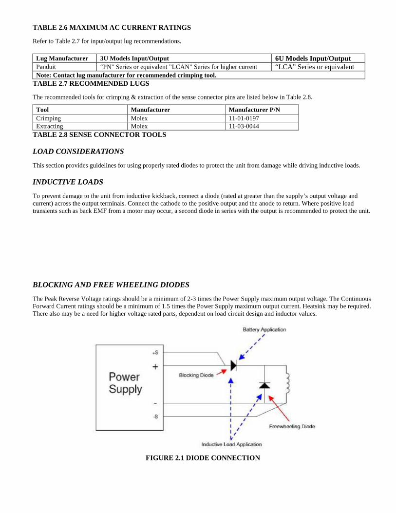
TABLE 2.6 MAXIMUM AC CURRENT RATINGS Refer to Table 2.7 for input/output lug recommendations. Lug Manufacturer 3U Models Input/Output 6U Models Input/Output Panduit “PN” Series or equivalent ”LCAN” Series for higher current “LCA” Series or equivalent Note: Contact lug manufacturer for recommended crimping tool.
TABLE 2.7 RECOMMENDED LUGS The recommended tools for crimping & extraction of the sense connector pins are listed below in Table 2.8.
Tool Manufacturer Manufacturer P/N Crimping Molex 11-01-0197 Extracting Molex 11-03-0044
TABLE 2.8 SENSE CONNECTOR TOOLS LOAD CONSIDERATIONS This section provides guidelines for using properly rated diodes to protect the unit from damage while driving inductive loads. INDUCTIVE LOADS To prevent damage to the unit from inductive kickback, connect a diode (rated at greater than the supply’s output voltage and current) across the output terminals. Connect the cathode to the positive output and the anode to return. Where positive load transients such as back EMF from a motor may occur, a second diode in series with the output is recommended to protect the unit. BLOCKING AND FREE WHEELING DIODES The Peak Reverse Voltage ratings should be a minimum of 2-3 times the Power Supply maximum output voltage. The Continuous Forward Current ratings should be a minimum of 1.5 times the Power Supply maximum output current. Heatsink may be required. There also may be a need for higher voltage rated parts, dependent on load circuit design and inductor values.
FIGURE 2.1 DIODE CONNECTION

OUTLINE DRAWINGS Figure 2.2 & Figure 2.3 shows the outline of the 3U and 6U models of the Medium Power SPS Series.

FIGURE 2.2 3U SPS 3-VIEW

FIGURE 2.3 6U SPS 3-VIEW

III: LOCAL OPERATION INTRODUCTION These sections contain information on how to locally program the SPS Series. Upon powering up, the power supplies default to local mode operation. All front panel keys may be used to control the power supply.
All operations performed in local mode, may also be performed in digital remote mode via PC or Computer. The unit indicates remote operation when the “RMT” indicator is shown on the display. STANDARD OPERATION This power supply has two basic operating modes: Constant Voltage Mode (CV) and Constant Current Mode (CC), and three control modes: Local Control Mode (default setting), Remote Analog Programming (external analog programming port) and Remote Digital Programming (PC) Mode. Both CV and CC operating modes are available regardless of which control mode is used. OPERATING MODES Whether controlled by local or remote programming, the power supply has two basic operating modes: Constant Voltage Mode and Constant Current Mode. The mode in which the power supply operates at any given time depends on the combination of:
• Output voltage setting VSET • Output current limit setting ISET • Resistance of the attached load RL
CONSTANT VOLTAGE MODE OPERATION The power supply will operate in constant voltage mode whenever the load current IL is less than the current limit setting ISET. Important Notes for CV Mode Operation (IL = VSET / RL):
1) In constant voltage mode, the power supply maintains the output voltage at the selected value (VSET) while the load current IL varies with the load requirements. In CV mode, the output voltage is regulated.
2) For proper operation in CV mode, the power supply requires loading of at least 10% of full current CONSTANT CURRENT MODE OPERATION The power supply will operate in constant current mode whenever the load resistance is low enough that the load current IL is equal to the current limit setting ISET. In local operation, by pressing CURR (a sub-function of the “8” key on the keypad), the current value can be changed, simply enter the desired current amount and press “Enter” to confirm. Important Note for CC Mode Operation (VL = ISET*RL) :
In constant current mode, the power supply maintains its output current at the ISET value while the voltage varies with the load requirements. AUTOMATIC MODE CROSSOVER This feature allows the power supply to auto-switch between CV or CC operating modes in response to changing load requirements. If, the power supply is operating in CV mode, and the load changed so that the load current became equal to the current limit setting, the power supply would automatically switch into CC mode and the output voltage would vary in response to changes in load current. If the additional load

were subsequently removed so that the load current is again less than the current limit setting, the supply would automatically return to CV mode. GENERAL INFORMATION
1. The power supplies are able to directly accept programming values of voltage, current and over
voltage. "When a valid input is made, the unit will round off the value to the nearest multiple of the resolution". If a non-valid input is made, the unit will display “--- OVERFLOW---” and retain it’s previously programmed setting.
2. Press the VOLT or CURR key to display or edit the V/I settings currently programmed. To change
this value, simply use the numeric keys to enter a value. If an error is made, press the "CLEAR" key and then reenter the correct value. Once the final value is set, press the "ENTER" key. After pressing the "ENTER" key, the VFD display returns to the metering mode.
For example, to recall a set voltage, press "VOLT" and then press "ENTER" or "CLEAR" key to
return unit to metering mode. 3. To view or change any of the output parameters (i.e. VOLT, CURR, OVSET, and VLIST) simply
press the desired function keys, enter the new value and press "ENTER" .
REMOTE INHIBIT SHUTDOWN For applications that require using remote ON-OFF control to the output, the power supply has various external shutdown/remote inhibit control methods, please refer to section, External Analog Programming (J1) in Section I for details.
SETTING VOLTAGE To locally program the voltage (VSET), press "VOLT" , enter the value and press "ENTER" . For example, if one wished to set a voltage of 3.99, press:
VOLT 3 ••••
9 9 ENTER The LCD displays 3.99 V and the unit returns to metering mode.
SETTING CURRENT To locally program the current (ISET), press "CURR" and enter the value and then press "ENTER" . For example, if one wishes to set a current of 1.69 amps, press:
CURR 1 ••••
6 9 ENTER
The LCD display 1.69 and the unit returns to metering mode.
OVER VOLTAGE (OVP) OPERATION The power supply has an over voltage protection (OVP) feature to guard against abnormal operating conditions such as voltage overshoot. When the supply’s output voltage exceeds a threshold voltage, the OVP is activated, and the unit disables the output. The LCD will indicate the condition.

The user can enable or disable the OVP circuit by pressing the "OVP ON/OFF (2)" key. When it is enabled the OVP enunciator is on. When the LCD displays “OVER VOLTAGE”, the over voltage protection circuit has been activated and the output is disabled. To reset, press the "CLEAR (RESET)" key. To turn the output on again, press the "OUT ON/OFF (1)” key. SETTING THE OVER VOLTAGE THRESHOLD To locally program the threshold voltage press "OV/TIME" , enter the value and press "ENTER" . For example, to program an over voltage value of 4.50V, press:
OV/TIME 4 ••••
5 0 ENTER When output voltage exceeds 4.50V, OVP is triggered, OVP annunciator is blinking, and the output is disabled. Important Notes: 1) When Remote sensing, please take into consideration the voltage drop across the load leads. The OV
programmed threshold is measured at the load terminals where the remote sense leads are connected.
2) In inductive load applications, a high-surge voltage would enable the OVP circuit and disable the output.
3) Also note the programming resolution and programming accuracy specifications
4) When the OVP circuit is disabled, the threshold voltage becomes invalid.
OVER CURRENT PROTECTION The power supply has an over current protection (OCP) feature to guard the supply against current overdraw. If the OCP feature is enabled and the supply switches to CC mode, the OCP protection will trigger when the current level exceeds the OCP level and then disable the output. The OCP threshold is programmable via the sub-function key OC. ENABLING / DISABLING OVER CURRENT PROTECTION To enable the over current protection circuit, press the "OCP ON/OFF (3)" key and the OCP annunciator is turned on. To disable the over current protection, press the "OCP ON/OFF (3)" key one more time and the enunciator is turned off. When the LCD displays “OVER CURRENT”, the over current protection circuit has been activated and the output is disabled. To reset, press the "OCP ON/OFF (3)" key and the enunciator will stop blinking. To turn the output on again, press the sub-function key "OCP ON/OFF" .
Important Notes:
1) OCP is set by the value of the current limit.
2) If OCP is enabled and the constant current Mode (CC) is activated, the power supply output is disabled.

TUNE MODE The Tune Mode provides a simple and accurate method to adjust the output voltage and current. Using the encoder, each digit can be fine tuned to obtain precise entries. When the SPS series power supply’s output is ON, you may press or hold the encoder to enter into the Tune Mode. This function allows you to edit voltage and current and select the desired digit for increment or decrement the value. In Tune Mode, the default cursor positioned at the lowest digit of voltage and current value. To turn right, it increment the digit value and carries to next digit. And to turn left, it decrement the digit and borrows to next digit. The output voltage and current values also refresh according to the new value setting. ENCODER OPERATION The AMREL SPS Series comes with a standard encoder at front control panel. See definition below. Definition for knob “Turn”: Turn right: 1. At “Menu Mode”, it is similar to “” keys.
2. At “Input Mode” or “Tune Mode”, it increments the digit value of the cursor location.
Turn left:
1. At “Menu Mode”, it is similar to “” keys. 2. At “Input Mode” or “Tune Mode”, it decrements the digit value of the cursor location.
Definition for knob “Press/Hold” Press: (Press and release)
1. At “Menu Mode”, it is similar to “CLEAR” keys. 2. At “Input Mode” or “Tune Mode”, it moves the cursor to left.
Hold: (Press and Hold for 2 seconds)
1. At “Menu Mode”, it is similar to “ENTER” key. 2. At “Metering Mode”, it is similar to “UTILITY” key.
ENABLING / DISABLING OUTPUTS
Please ensure no live voltage is present at the dc output terminal before attempting to connect or disconnect loads, as it may be unsafe to handle. Please use a hand-held DVM to ensure no live voltages are present. All models of the SPS Series have the capability of disabling their outputs to allow for entering new operating parameters or changing/connecting loads. Once the setting or configuration changes have been completed, the user can enable the SPS output via the OUT ON/OFF key to operate at new settings. The output is enabled or disabled by pressing the OUT ON/OFF key. To return the supply to normal operation, press the "OUT ON/OFF (1)" key again to toggle the output on. The SPS Series output is enabled or disabled by selecting the channel/s and pressing the "OUT (ON/OFF) (1)" key.
CAUTION

UTILITY MENU Follow simple steps below for navigating the various functions in the Utility Menu. 1. Local Meter Display as shown when turned the power switch “ON”. Press UTILITY key to enter into the SPS Function Menu, press ENTER for menu selection mode. 2. Use key #6 as () and #4 as () to select menu option. To configure the number of iterations for VLIST & ILIST , select LIST CYCLE and press ENTER key to accept the value then press CLEAR key to return to local meter display. 2. Use key #6 () and #4 () to select menu option, and press ENTER to enter edit mode. Select the LIST function time unit, MILLISECOND or SECOND, and press ENTER key to accept the selection. Press CLEAR to return to local meter display. 3. Use key #6 () or #4 key () to select menu option, and press ENTER to enter edit mode. Use key #6 () and #4 () to select the desired GPIB address (0 – 31). Press ENTER key to accept the entry then press CLEAR key to back to local meter display.
4. Use key #6 () or #4 key () to select menu option, and press ENTER to enter edit mode. Use key #6 () and #4 () to select DC Output On or DC Output Off upon ac power-on. Press ENTER key to accept the setting entry then press CLEAR key to return to local meter display. 5. Use key #6 () or #4 key () to select menu option, and press ENTER to enter edit mode. Use key #6 () or #4 key () to select desired Baud Rate: 2400 / 4800 / 9600 / 19200 / 38400 / 57600 / 115200. Press ENTER to accept setting and press CLEAR to return to local meter display. 6. Use key #6 () or #4 key () to select menu option, and press ENTER to enter edit mode. Use key #6 () or #4 key () to select desired EOS Code: NONE / CR / LF / CR+LF. Press ENTER to accept EOS Code setting, then press CLEAR key to return to local meter display. 7. Use key #6 () or #4 key () to select menu option, and press ENTER to enter edit mode. Use key #6 () or #4 key () to enable (ON) or disable (OFF) the buzzer. Press ENTER to accept the buzzer setting then press CLEAR key to return to local meter display. 8. Use key #6 () or #4 key () to select menu option, and press ENTER to enter edit mode. Use key #6 () or #4 key () to configure the EXT. CONTROL STATE :
a. ON: External Analog Control Only b. OFF: External Analog Control and Local Control settings are additive
VSET5.000 ISET1.000
OFF LCL
UTILITY
LIST CYCLE
UTILITY
DEFAULT OUTPUT
UTILITY
RS-232 SPEED
UTILITY
EOS CODE
UTILITY
BUZZER
UTILITY
GPIB ADDRESS
UTILITY
EXT. CONTROL
UTILITY
LIST TIME UNIT

Press ENTER to confirm selection and CLEAR to return to local meter display
9. Use key #6 () or #4 key () to select menu option, and press ENTER to enter edit mode. Use key #6 () or #4 key () to select between Panel Enable Mode and Panel Password Mode, and then press ENTER to confirm selection:
a. PANEL ENABLE MODE: Press ENTER then use key #6 () or #4 key () to enable/disable (On/Off). Press ENTER key to accept the password then press CLEAR key to return to local meter display.
b. PANEL PASSWORD MODE: Enter the desired 6 digit numerical password, and press CLEAR key to return to local meter display.
10. Use key #6 () or #4 key () to select menu option, and press ENTER to enter edit mode. Use key #6 () or #4 key () to select between SERIAL NO., INTERFACE, and CODE (see description below), and press ENTER.
a. SERIAL NO.: Press ENTER to display the MAC Address of the SPS. b. INTERFACE: Press ENTER to display the available interfaces. c. CODE: To obtain unavailable Interface options, please contact AMREL Customer
Service. For Interface Activation, press Enter for code entry and press Enter once entry is completed. Use the INTERFACE menu option to verify available interface options.
Press ENTER to confirm selection(s) and CLEAR to return to local meter display 11. Use key #6 () or #4 key () to select menu option, and press ENTER to enter edit mode. Use key #6 () or #4 key () to select between ADDRESS, NETMASK, or GATEWAY (see description below), and press ENTER.
a- ADDRESS: Press ENTER to input IP address. Press ENTER to accept the IP address entry, and press CLEAR to return to local meter display.
b- NETMASK: Press ENTER to input NETMASK setting. Press ENTER to accept the entry, and then press CLEAR to return to local meter display.
c- GATEWAY: Press ENTER to enter the GATEWAY setting. Press ENTER key to accept the address then press CLEAR to return to local meter display.
12. After configuring UTILITY menu options, press CLEAR or UTILITY to return to local meter display.
FRONT PANEL LOCK OPERATION This SPS series power supply has the ability to lock the front panel and prevent unwanted access. To enable the lockout feature, activate the function via FUNC key and upon power-on (or power cycle) the front panel will be locked out. Please see below for the procedures to configure front panel lockout:
1. Press UTILITY then use the key to select PANEL LOCK entry and press ENTER to confirm. 2. Use the key to select PANEL ENABLE or PANEL PASSWORD.
Panel Enable:
1. Select PANEL ENABLE and press ENTER key.
UTILITY
PANEL LOCK
UTILITY
NETWORK
UTILITY
AUTHENTICATE

2. Use the key to enable (ON) or disable (OFF) lockout for the front panel keys. 3. Press ENTER to confirm your setting. 4. Press CLEAR return to local meter display.
Panel Password:
1. Select PANEL PASSWD and press ENTER key. 2. Enter the password and press ENTER key to accept your password. (1 to 6 digit password) 3. Press CLEAR key twice to back to main local display.
STEPPING MODE Voltage/Current List Edit Mode: Voltage/Current List or programming permits the user to program a sequence of different voltage or current outputs with its applied time duration via front panel keypad or PC commands. VLIST or ILIST operate independently and is activated using keypad or PC command.
VLIST setting:
1. At metering menu; Press # 4 key (VLIST) to enter into the voltage list edit mode. 2. Use or to select which VLIST entry to edit. 3. Press # 7 key (VOLT) to configure the voltage value for this VLIST entry. 4. Press # 9 key (OV/TIME) to set the VLIST dwell time (unit in ms). 5. Repeat step 3 to 5 to edit more VLIST entries. 6. Press CLEAR key to return to local meter display.
ILIST setting:
1. At local meter display screen; Press # 5 key (ILIST) to enter into the current list edit mode. 2. Use or to select which ILIST entry to edit. 3. Press # 8 key (CURR) to configure the current setting for this VLIST entry. 4. Press # 9 key (OV/TIME) to set the VLIST dwell time (unit in ms). 5. Repeat step 3 to 5 to edit more VLIST entries. 6. Press CLEAR key to return to local meter display.
Voltage/Current list operation:
1. At the local meter display screen; Press key# 0 (VLIST ON/OFF) or decimal key ( . ) to enable or disable the VOLTAGE (VLIST) or CURRENT (ILIST) list operation.
2. When LIST operation is ON, the display shows “VLIST ON” OR “ILIST ON”.
Important Notes: 1) LIST operation can only be enabled when power supply output is activated. 2) Only a single VLIST or ILIST can run at one time. 3) VLIST and ILIST cannot be operated simultaneously.
LIST CYCLE List Cycle is the number of cycles the VLIST or ILIST is instructed to run. Each cycle translates to the execution of a single iteration of the entries stored in the VLIST or ILIST sequence. The cycles can be repeated by selecting the number of cycles or repeated indefinitely. Example: Set LIST cycle to 10
1. Press UTILITY. 2. Use key to select LIST CYCLE, and then press ENTER. 3. Use or to set the LIST CYCLE to 10, and then press ENTER. 4. Press CLEAR to return to local meter display.
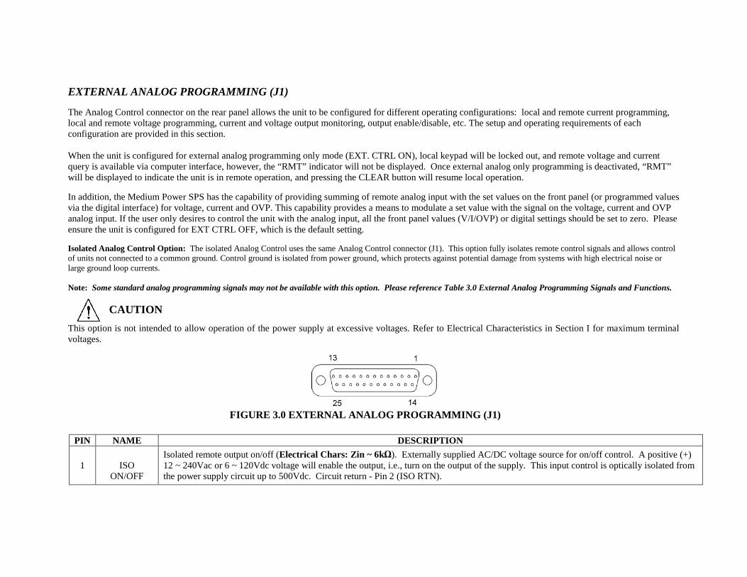
EXTERNAL ANALOG PROGRAMMING (J1) The Analog Control connector on the rear panel allows the unit to be configured for different operating configurations: local and remote current programming, local and remote voltage programming, current and voltage output monitoring, output enable/disable, etc. The setup and operating requirements of each configuration are provided in this section. When the unit is configured for external analog programming only mode (EXT. CTRL ON), local keypad will be locked out, and remote voltage and current query is available via computer interface, however, the “RMT” indicator will not be displayed. Once external analog only programming is deactivated, “RMT” will be displayed to indicate the unit is in remote operation, and pressing the CLEAR button will resume local operation. In addition, the Medium Power SPS has the capability of providing summing of remote analog input with the set values on the front panel (or programmed values via the digital interface) for voltage, current and OVP. This capability provides a means to modulate a set value with the signal on the voltage, current and OVP analog input. If the user only desires to control the unit with the analog input, all the front panel values (V/I/OVP) or digital settings should be set to zero. Please ensure the unit is configured for EXT CTRL OFF, which is the default setting. Isolated Analog Control Option: The isolated Analog Control uses the same Analog Control connector (J1). This option fully isolates remote control signals and allows control of units not connected to a common ground. Control ground is isolated from power ground, which protects against potential damage from systems with high electrical noise or large ground loop currents. Note: Some standard analog programming signals may not be available with this option. Please reference Table 3.0 External Analog Programming Signals and Functions.
This option is not intended to allow operation of the power supply at excessive voltages. Refer to Electrical Characteristics in Section I for maximum terminal voltages.
PIN NAME DESCRIPTION
1
ISO ON/OFF
Isolated remote output on/off (Electrical Chars: Zin ~ 6kΩ). Externally supplied AC/DC voltage source for on/off control. A positive (+) 12 ~ 240Vac or 6 ~ 120Vdc voltage will enable the output, i.e., turn on the output of the supply. This input control is optically isolated from the power supply circuit up to 500Vdc. Circuit return - Pin 2 (ISO RTN).
FIGURE 3.0 EXTERNAL ANALOG PROGRAMMING (J1)
CAUTION

2 ISO RTN Isolated circuit return used with isolated on/off control J1-1 and J1-14.
3 REM OV
SET Remote over-voltage set (Electrical Chars: Zin ~ 20kΩ). A remote signal sets the over-voltage trip level. 0.25 ~ 5.5Vdc = 5 ~ 110%. Apply a 10.5Vdc to 13.3Vdc signal for 7 seconds to reset an OVP condition. Circuit return - Pin 6 (COM).
4 VP RTN Voltage programming return (Electrical Chars: Zin ~ 10kΩ). Used with J1-9, J1-15 or J1-21 and must be referenced to Pin 6 (COM) circuit common.
5 ON/OFF Remote output on/off (Electrical Chars: Must sink ~ 1mA to enable). Switch/relay contacts or a direct short between this terminal and Pin 6 (COM) circuit common, enables the output, i.e., turns on the output of the supply.
6 COM1 Circuit common. Electrically equal to Pin 24. Same potential as the negative output terminal.
7 IMON Output current monitor (Electrical Chars: Zout ~ 100Ω). 0 ~ 10Vdc equals 0 ~ 100% rated current. Min. load resistance - 10kΩ. Circuit return - Pin 6 (COM).
8 NOT USED
9 VP 5V Remote voltage programming using a 0 ~ 5Vdc source (Electrical Chars: Zin ~ 10kΩ). Do not exceed 13.3Vdc. Circuit return - Pin 4 or Pin 20 (VP RTN).
10 IP 5V Remote current programming using a 0 ~ 5Vdc source (Electrical Chars: Zin ~ 10kΩ). Do not exceed 13.3Vdc. Circuit return – Pin 23 or Pin 25 (IP RTN).
11 NOT USED 12
13
14 ISO
TTL/CMOS
Isolated TTL/CMOS on/off control (Electrical Chars: Zin ~ 2.2kΩ). A high state TTL/CMOS voltage enables the output, i.e., turns on the output of the supply, and a low state or open connection disables the output, i.e. turns off the output of the supply. Circuit return - Pin 2 (ISO RTN).
15 VP 10V Remote voltage programming using a 0~10Vdc source (Electrical Chars: Zin ~ 20kΩ). Do not exceed 25Vdc. Circuit return – Pin 4 or Pin 20 (VP RTN).
16 IP 10V Remote current programming using a 0~10Vdc source (Electrical Chars: Zin ~ 20kΩ). Do not exceed 25Vdc. Circuit return – Pin 23 or Pin 25 (IP RTN).
17 FAULT Fault state output (Electrical Chars: Zout ~ 100Ω). A high state (approximately +10Vdc) indicates a converter, temperature or bias supply fault, and the LED on the front panel will illuminate. Circuit return – Pin 6 (COM).
18 S/D FAULT Shutdown fault (Electrical Chars: Zout ~ 100Ω). This terminal goes to high state in the event of converter, temperature, overvoltage or bias supply fault. A 7Vdc ~ 13.3Vdc signal can be applied to this pin to shutdown the output of the unit. An 8Vdc minimum output signal is provided into a 10kΩ minimum load, in the event of an internally generated shutdown. Circuit return – Pin 6 (COM).
19 VMON Output voltage monitor (Electrical Chars: Zout ~ 100kΩ). 0 ~ 10Vdc equals to 0 ~ 100% rated voltage. Minimum load resistance 10kΩ.
Circuit return – Pin 6 (COM).
20 VP RTN Voltage programming return (Electrical Chars: Zin ~ 10Ω). Used with J1-9, J1-15 or J1-21 and must be referenced to Pin 6 (COM) circuit common.
21 VP RES2 1 milliamp current source for remote voltage programming using resistance (Electrical Chars: ~10.8V Compliance). 0 ~ 5kΩ resistor referenced to Circuit return Pin 23 or Pin 25 (IP RTN) will program the output voltage from 0 ~ 100%.
22 IP RES2 1 milliamp current source for remote current programming using resistance (Electrical Chars: ~10.8V Compliance). 0 ~ 5kΩ resistor referenced to Circuit return Pin 23 or Pin 25 (IP RTN) will program the output current from 0 ~ 100%.
23 IP RTN Current programming return (Electrical Chars: Zin ~ 10kΩ). Used with J1-10, J1-16 or J1-22 & must be referenced to Pin 6 (COM) circuit common.
24 COM1 Circuit common. Electrically equal to Pin 6. Same potential as the negative output terminal.
25 IP RTN Current programming return (Electrical Chars: Zin ~ 10kΩ). Used with J1-10, J1-16 or J1-22 and must be referenced to Pin 6 (COM) circuit common.
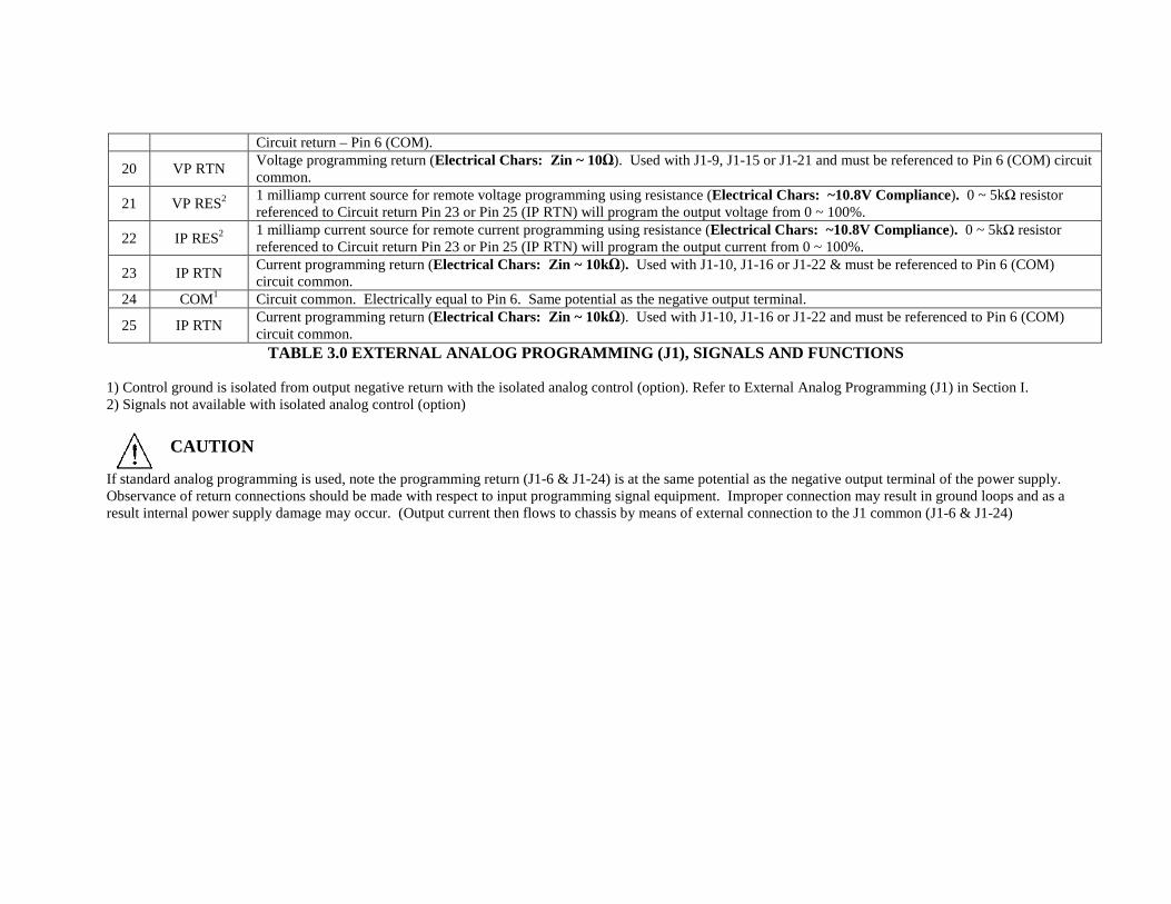
TABLE 3.0 EXTERNAL ANALOG PROGRAMMING (J1), SIGNALS AND FUNCTIONS 1) Control ground is isolated from output negative return with the isolated analog control (option). Refer to External Analog Programming (J1) in Section I. 2) Signals not available with isolated analog control (option)
If standard analog programming is used, note the programming return (J1-6 & J1-24) is at the same potential as the negative output terminal of the power supply. Observance of return connections should be made with respect to input programming signal equipment. Improper connection may result in ground loops and as a result internal power supply damage may occur. (Output current then flows to chassis by means of external connection to the J1 common (J1-6 & J1-24)
CAUTION

REMOTE CURRENT PROGRAMMING Remote current programming is summed with the front panel or digital setting when External Control is set to OFF (see EXT. CONTROL in UTILITY menu of Section III). Remote current programming is used for applications that require the output current be programmed (controlled) from a remote source. An external resistance or external voltage source may be used as a programming device. When using remote current programming, a shielded, twisted-pair, hookup wire is recommended to prevent noise interference with programming signals. REMOTE CURRENT PROGRAMMING USING RESISTANCE The resistance coefficient for remote current programming is 5k ohms/100% rated output with respect to terminal J1-23 (IP RTN). The programming current from terminal J1-22 (IP RES) is factory set for 1 milliampere. This yields a coefficient of 1.0% of rated output current for each 50 ohms. If multiple switches or relays are used to program different levels, make-before-break contacts are recommended. Note that if an external resistance is used for remote programming, the current programming return (IP RTN), terminal J1-23, must be connected directly to or within ±3 volts of the power supply common terminal, J1-24. See Figure 3.1 for connection requirements.
FIGURE 3.1 REMOTE CURRENT PROGRAMMING USING RESISTA NCE
REMOTE CURRENT PROGRAMMING USING A 0-5 VDC or 0-10 VDC SOURCE A DC voltage source for remote current programming is connected between J1-10 (IP 5V) or J1-16 (IP 10V) and the return terminal J1-23 (IP RTN). Note that the return terminal J1-23 (IP RTN) must be referenced directly to or within ±3V of the power supply common, J1-24. The voltage coefficient for 5V remote current programming is 50 millivolts = 1% of rated output, i.e., for a 300 amp model, each 50 millivolts of programming voltage equals 3 amps of output current. The voltage coefficient for 10V remote current programming is 100 millivolts = 1% of rated output, i.e., for a 300 amp model, each 100 millivolts of programming voltage equals 3 amps of output current. See Figure 3.2 for connection requirements.
FIGURE 3.2 REMOTE CURRENT PROGRAMMING USING 0-5 V DC or 0-10 VDC VOLTAGE SOURCE
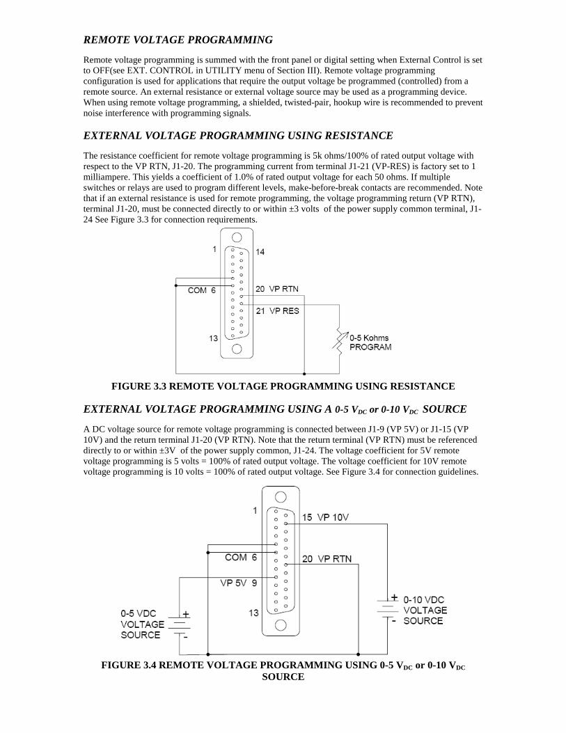
REMOTE VOLTAGE PROGRAMMING Remote voltage programming is summed with the front panel or digital setting when External Control is set to OFF(see EXT. CONTROL in UTILITY menu of Section III). Remote voltage programming configuration is used for applications that require the output voltage be programmed (controlled) from a remote source. An external resistance or external voltage source may be used as a programming device. When using remote voltage programming, a shielded, twisted-pair, hookup wire is recommended to prevent noise interference with programming signals. EXTERNAL VOLTAGE PROGRAMMING USING RESISTANCE The resistance coefficient for remote voltage programming is 5k ohms/100% of rated output voltage with respect to the VP RTN, J1-20. The programming current from terminal J1-21 (VP-RES) is factory set to 1 milliampere. This yields a coefficient of 1.0% of rated output voltage for each 50 ohms. If multiple switches or relays are used to program different levels, make-before-break contacts are recommended. Note that if an external resistance is used for remote programming, the voltage programming return (VP RTN), terminal J1-20, must be connected directly to or within ±3 volts of the power supply common terminal, J1-24 See Figure 3.3 for connection requirements.
FIGURE 3.3 REMOTE VOLTAGE PROGRAMMING USING RESISTA NCE
EXTERNAL VOLTAGE PROGRAMMING USING A 0-5 VDC or 0-10 VDC SOURCE A DC voltage source for remote voltage programming is connected between J1-9 (VP 5V) or J1-15 (VP 10V) and the return terminal J1-20 (VP RTN). Note that the return terminal (VP RTN) must be referenced directly to or within ±3V of the power supply common, J1-24. The voltage coefficient for 5V remote voltage programming is 5 volts = 100% of rated output voltage. The voltage coefficient for 10V remote voltage programming is 10 volts = 100% of rated output voltage. See Figure 3.4 for connection guidelines.
FIGURE 3.4 REMOTE VOLTAGE PROGRAMMING USING 0-5 V DC or 0-10 VDC SOURCE

REMOTE SENSING Remote voltage sensing is recommended at all times, whether the sensing leads are connected to the load or directly to the output terminals. Remote sensing at the load provides the best load regulation. In applications where the load is located some distance from the power supply, or the voltage drop of the power output leads significantly interferes with load regulation, remote voltage sensing should definitely be used. The voltage accuracy specifications are valid only with remote sense connected. Disconnecting the remote sense leads will introduce an error, with the output voltage increasing. The error occurs because an additional resistance (PTC local resistor network in) is added in the circuit of the resistor divider for voltage sensing, to provide the default local sensing of the output voltage at the output terminals. When remote sense is connected the PTC local resistor network is short-circuited, effectively removing it from the circuit.
FIGURE 3.5 LOCAL/REMOTE VOLTAGE SENSING
If the power supply is operated with load power lines disconnected and sensing line connected, internal power supply damage may occur. (Output current then flows through sensing terminals). To use remote voltage sensing, connect the power supply as described below. See Figure 3.6 for connection requirements. Connect sensing leads from the load positive to J3-1 and the load negative to J3-2. A shielded, twisted-pair, hookup wire is recommended to avoid potential noise interference.
FIGURE 3.6 REMOTE SENSING OPERATION AT THE LOAD
CAUTION
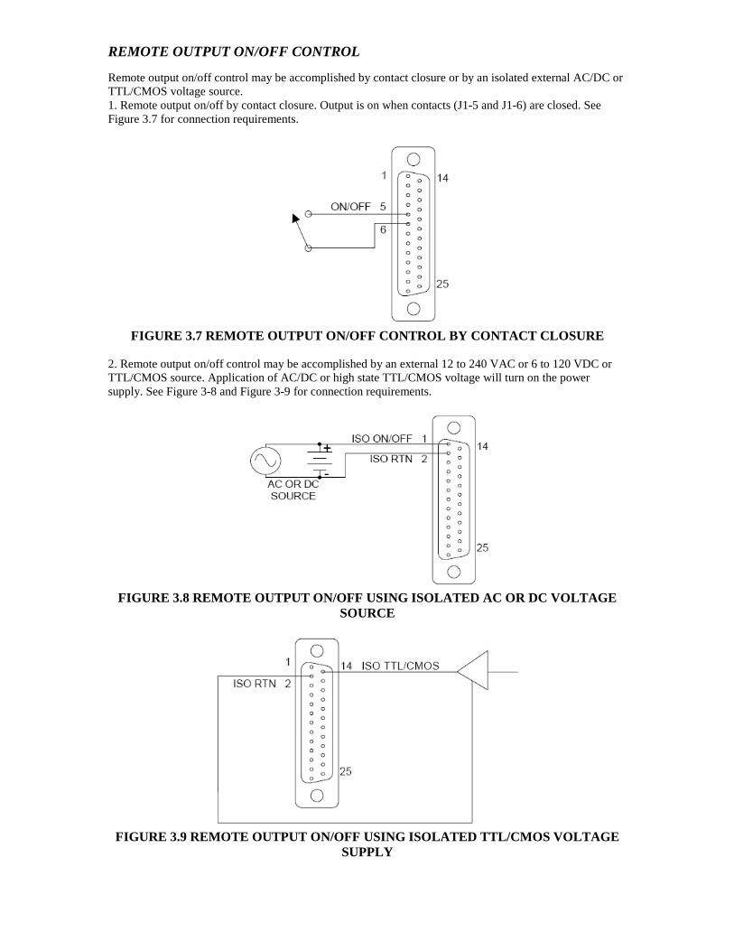
REMOTE OUTPUT ON/OFF CONTROL Remote output on/off control may be accomplished by contact closure or by an isolated external AC/DC or TTL/CMOS voltage source. 1. Remote output on/off by contact closure. Output is on when contacts (J1-5 and J1-6) are closed. See Figure 3.7 for connection requirements.
FIGURE 3.7 REMOTE OUTPUT ON/OFF CONTROL BY CONTACT CLOSURE
2. Remote output on/off control may be accomplished by an external 12 to 240 VAC or 6 to 120 VDC or TTL/CMOS source. Application of AC/DC or high state TTL/CMOS voltage will turn on the power supply. See Figure 3-8 and Figure 3-9 for connection requirements.
FIGURE 3.8 REMOTE OUTPUT ON/OFF USING ISOLATED AC O R DC VOLTAGE
SOURCE
FIGURE 3.9 REMOTE OUTPUT ON/OFF USING ISOLATED TTL/ CMOS VOLTAGE
SUPPLY

REMOTE OVERVOLTAGE SETPOINT
Do not program the remote overvoltage set point greater than 10% (5.5Vdc) above the power supply rated voltage (except as note) as internal power supply damage may occur. Remote OVP programming is summed with the front panel or digital setting when External Control is set to OFF (see EXT. CONTROL in UTILITY menu of Section III). A remote DC voltage source can be connected externally between terminals J1-6 (COM) and J1-3 (REM OV SET) to set the output overvoltage trip level. A 0.25-5.5 VDC signal equals 5-110% of rated output voltage. See Figure 3.10 for connection requirements.
FIGURE 3.10 REMOTE OVERVOLTAGE SET USING DC VOLTAGE SOURCE
Note: To reset an OVP externally, apply a 10.5–13.3 VDC signal to J1-3 for a minimum of seven (7) seconds. REMOTE SHUTDOWN (S/D) A remote +12 VDC voltage can be connected externally between terminals J1-18 (S/D Fault) and J1-24 (COM) to disable, i.e., shut down the output of the power supply. Disabling or opening the +12 VDC signal will allow the unit to revert to normal operation.
FIGURE 3.11 REMOTE SHUTDOWN USING DC VOLTAGE SOURCE
PARALLEL AND SERIES OPERATION The following modes of operation are used for applications requiring more current or voltage than is available from a single power supply. To meet the requirements for greater output voltage or current, two supplies may be connected in series or up to five connected in parallel.
CAUTION

PARALLEL OPERATION In order to connect up to five power supplies in parallel, use a “Master/Slave” daisy-chain wiring configuration as follows (refer to Figure 3.12: (Note that there are two separate 9-pin connectors on the upper left rear panel of each power supply, marked “PAR OUT” and “PAR IN”). 1. Beginning with the power supply designated (by you) as the Master power supply, use an interface
cable (P/N: 094021) to connect the PAR OUT connector on the designated Master power supply to the PAR IN connector on the second power supply (Slave 1).
2. On the second power supply (Slave 1), use another interface cable to connect the PAR OUT connector to the 3rd power supply’s (Slave 2) PAR IN connector. Continue these interconnections up to a max of 5 power supplies.
3. Connect the Positive output terminals of all the power supplies and the Load.
4. Connect the Negative output terminals of all the power supplies and the load.
5. Confirm that there are no shorts between the Positive and Negative output terminals.
6. Referring to Figure 3.12, connect twisted pair cables as follows:
All slave units shall have twisted pairs from their SENSE terminals to their output terminals, as appropriate.
For Remote Sense, master unit shall have a twisted pair from its own SENSE terminals to Load’s output terminals.
For Local Sense, the master unit shall have a twisted pair from its own SENSE terminals to its own output terminals.
Ensure that all twisted pair cables are as short as possible.
NOTE: The twisted pair cable length must be as short as possible
FIGURE 3.12 PARALLEL AND REMOTE/LOCAL SENSE CONNECT IONS
Note: The OVP circuit remains active for all units in parallel operation. If the units are set to different OVP levels, the paralleled system will trip according to the lowest setting. For ease of use, adjust the OVP levels for the slaves to maximum and adjust the master OVP level to the desired setting.

SERIES OPERATION
Series operation is used to obtain a higher voltage single output supply using two units. Connect the negative terminal (–) of one supply to the positive terminal (+) of the next supply of the same model. The total voltage available is the sum of the maximum voltages of each supply (add voltmeter readings). Important Notes:
• Under no condition should the negative (–) output terminal of any power supply exceed 300V to Earth ground. This is limited by the creepage/clearance distances and insulation internal to the power supply. If a higher output voltage range is required, contact the Sales Department or Customer Service for availability.
• Max allowable current for a series string of power supplies is the rated output current of a single supply in the string.
• The remote sense leads of each supply should be connected across the individual outputs, and not across the total series string.
• A free-wheeling diode (power diode capable of the maximum current of the series set connected in parallel, but reverse biased) is recommended to protect against sinking current into a supply should one supply be “ON” while the other is “OFF.” (Refer to Section II , Blocking and Free Wheeling Diodes).
MASTER-SLAVE OPERATION When configuring multiple units for master-slave operation, please use the backdoor menu option to setup the number of units connected. The configuration will provide the sum of the current read back of the connected units. Please follow the procedures below.
1) Press ENTER and “.” keys simultaneously (this activates the backdoor menu) 2) Press ENTER and “0” keys simultaneously (this will take you into the backdoor menu) 3) Scroll to the Master/Slave menu option via the encoder 4) Select the number of desired setting and press ENTER MASTER ONLY MASTER + 1 SLAVE MASTER + 2 SLAVES MASTER + 3 SLAVES MASTER + 4 SLAVES MASTER + 5 SLAVES 5) Press CLEAR until the screen returns to metering mode
6) Press ENTER and “.” keys simultaneously (deactivates the backdoor menu), then power cycle all units Once the units are connected and configured for Master-slave operation, the meters on the slave units are disabled. The master-slave setting will allow the master unit to sum the correct number of channel current readings to display on the master unit. For example, if the “MASTER + 4 SLAVES” configuration is selected, the master unit will display the current reading sum of 5 units (1 master unit + 4 slave units).
Note 1: The current programming and read back specification in Section I is for a single standalone unit Note 2: Please ensure all units are power-cycled after master-slave operation
FLOATING AND POLARIZED OUTPUT The Medium Power SPS Series power supply can be configured for a Positive or Negative supply configuration, as well as standard operation as a floating output supply. Floating Output
The output terminals are normally floating from chassis to ground. No extra steps or connections are required for a floating input.
Positive Supply Setup Attach the negative output terminal to the supply chassis. The output reference is now chassis ground. When the output voltage is set or programmed, the supply will output a positive potential from chassis ground.

Negative Supply Setup Attach the Positive output terminal to the supply chassis. The output reference is now chassis ground. When the output voltage is set or programmed, the supply will output a negative potential from chassis ground.
Floating the negative output terminal floats the power supply’s internal control circuitry common level to the same potential as the negative output terminal. On a standard non-isolated supply the common of the analog control connector (J1) floats at the same potential as the negative output terminal. Damage may occur if the non-isolated analog control connector of a supply is connected to an external ground referenced input/output device. Such a connection creates ground loop currents. To correct ground loop current problems the Isolated Analog option is advised in order to isolate the external ground reference signals from the internal control circuitry of the supply.
CAUTION
IV. REMOTE OPERATION INTRODUCTION AMREL Medium Power SPS series Power Supplies have GPIB, RS-232, USB and Ethernet (OPTIONAL) interfaces for users to remotely operate. GPIB CAPABILITIES OF THE POWER SUPPLY All Power Supply functions except for setting the GPIB address are programmable over the GPIB. GPIB Address The power supply operates from a GPIB address that is set through the front panel with the GPIB ADDRESS function of the UTILITY MENU; refer to UTILITY MENU in Section III, Operation. RS-232 CAPABILITIES OF THE POWER SUPPLY The power supply provides an RS-232 programming interface. All SCPI commands are available through RS-232 programming. When the RS-232 interface is selected, the GPIB interface and Ethernet interface should not be operated. NOTE: The RS-232 baud rate settings in your program must match the settings stored in non-volatile
memory. If you need to change the baud rate setting, using command “SYST:CONS:BAUD <value>”. Please refer to the command description for details of using this command.
RS-232 Flow Control The RS-232 interface flow control options are default set (fixed) for the power supply as following:
• Parity: NONE • Data bit: 8 • Stop bit: 1 • Start bit: 1 • XON-XOFF: OFF • RTS-CTS: OFF
Baud Rate You can select one of the following baud rates from the front panel, which is stored in non-volatile memory: 2400 / 4800 / 9600 / 19200 / 38400 / 57600 / 115200. (The default baud rate is set to 115200) RS-232 Returned String Format For non-query commands: OK + LF + CR; For queries: OK + LF + CR + returned value + LF + CR + OK + LF + CR. Note: Using RS-232 interface to get the voltage or current read back value, a minimum 50 milliseconds delay must be added to the application program. RS-232 Troubleshooting If you are having trouble communicating over the RS-232 interface, check the following:
• The computer and the SPS unit must be configured for the same baud rate, parity, number of data bits, and flow control options. Note that the SPS unit is configured for 1 start bit and 1 stop bit (these values are fixed).
• The correct interface cables or adaptors must be used. • The interface cable must be connected to the correct serial COM port on the computer.

RS-232 serial connection
D-SUB CONNECTOR (DB-9 FEMALE)
PIN 1 ---NO CONNECTION PIN 2 ----------------------RXD PIN 3 ----------------------TXD PIN 4 ----------------------DTR PIN 5 ----------------------GND PIN 6 ---NO CONNECTION
PIN 7 ----------------------RTS PIN 8 ---NO CONNECTION PIN 9 ---NO CONNECTION
Note: The D-SUB Female Connector TXD and RXD pins are internally swapped. Therefore, interface cable between power supply and computer (controller) should not swap pins, such as a Null Modem cable. USB CAPABILITIES OF THE POWER SUPPLY
Please install USB Driver from utilities CD and follow the included installation instructions. ETHERNET CAPABILITIES OF THE POWER SUPPLY The power supply provides an Ethernet programming interface as optional. All SCPI commands are also available through Ethernet programming. When the Ethernet interface is selected, the GPIB interface and RS-232 interface should not be operated. Obtain Network Information To connect the power supply to the network, you only need a network cable with RJ-45 connector. No transceiver is necessary. However, you need to obtain the following information from the power supply unit and your network administrator: 1. Power supply Ethernet MAC ID Address: The MAC ID is a twelve digit string that uniquely identifies the power supply unit, and can be queried. 2. Network information: 1) DHCP server enabled? Yes or no. 2) Power supply IP address: . . . 3) Gateway IP address: . . . 4) Subnet mask: . . . Setting the Power Supply Ethernet Parameters You need to set the power supply Ethernet IP address first. The power supply IP address uniquely identifies the power supply to other devices on the network, and is required for the power supply to communicate over the network. 1. Ethernet Network settings: DHCP supported. The purpose of a DHCP (Dynamic Host
Configuration Protocol) server is to issue an IP address to a network device that requests an address. The IP address enables the device to communicate with the network. This is similar to personal computer Plug & Play concept.
The following procedure presumes that your power supply has the Ethernet option and you have connected the power supply to your network. If your network supports DHCP server, do the following: 1) Power on the power supply.

2) Set IP address as: “0.0.0.0” using command: “SYST:NET:ADDR 0.0.0.0”. 3) Set Net mask to “0.0.0.0” using command: “SYST:NET:SUBN 0.0.0.0”. 4) Set network gateway as “0.0.0.0” using command: “SYST:NET:GAT 0.0.0.0”. Note: If the DHCP server assign a dynamic IP address, then the value of the power supply IP address maybe different each time you power on the power supply. However, if you intend to remotely control the power supply, a static IP address is more convenient, as the power supply IP address does not change, making it easier for remote devices to access power supply.
2. Ethernet Network settings: DHCP not supported. If your network does not support DHCP server,
you must enter the Ethernet settings manually which you obtained from your network administrator. The following procedure presumes that your power supply has the Ethernet option and you have connected the power supply to your network. If your network does not support DHCP server, do the following: 1) Power on the power supply. 2) Set IP address as: “value” using command: “SYST:NET:ADDR <value>” where the value is
assigned by your network administrator. 3) Set IP net mask as: “value” using command: “SYST:NET:SUBN <value>” where the value is
provided by your network administrator. 4) Set IP network gateway as: “value” using command: “SYST:NET:GAT <value>” where the value
is provided by your network administrator. Using AMREL software tools to communicate with your power supply via Ethernet interface. AMETEK Programmable Power provides software tools for you to configure and communicate with your power supply. Please contact customer support for details. One of the most convenient tools for you to choose is AMREL eTool4-ConfigTool. This software tool automatically checks all connected power supply units on Ethernet when both PC and the power supply units are connected to Ethernet, along with basic information of the power supply units, such as model number, maximum voltage and current, and so on. Also, it automatically sets Ethernet configurations for all connected power supply units if your network is DHCP enabled. This software tools comes with your purchase of the unit, or you can download it from AMREL ftp site. Please contact AMREL customer support for details or refer to the following. Please do the following steps to download, install and use eTool4-ConfigTool: 1. Installation:
1) Copy all the needed files to a local computer from the AMETEK Programmable Power website.
2) Run setup.exe file and follow the on screen instructions. 3) Choose “Start | Programs (or All Programs for Windows XP) | Config Tool” to run the
program.
2. Configure Instrument:
1) When the program first runs, the software automatically search the connected instruments and the following three panel show up:

2) If Users’ local network supports DHCP server, users can just click “Yes” to configure all equipments to accept DHCP. Otherwise, just click “No” to ignore it.
3) The following panel then shows up for users to choose a unit to run. Users can select a unit from the instrument list and double click the row. The unit configuration panel then shows up for users to simply configure the unit.

4) Most of the information in the following device configuration panel is read from the instrument and displayed to users. It’s not for users to make changes. However, users still can operate on the following settings: Beep on/off, Output when power on, VSET, ISET and OUT state by just configuring the corresponding areas showing in the following panel.
3. Close the Program.
1) Click “Close IO”.
2) Click close program icon “ ” to exit the program.
Ethernet returned data string format:
For non-query commands: OK + <EOI character>; For queries: OK + <EOI character> + returned value + <EOI character> + OK + <EOI character>.

PROGRAMMING COMMAND SET FOR SPS SERIES POWER SUPPLY This section gives the syntax and parameter for all the programming commands used by AMREL SPS series power supply, including the terms, symbols, and syntactical structures used here and give an introduction to programming. You should also be familiar with front panel operation in order to understand how the power supply functions. The programming examples are simple applications of SCPI commands. Because the SCPI syntax remains the same for all programming languages, the examples given for each command are generic. Syntax Forms Syntax definitions use the long form, but only short form headers (or "keywords")
appear in the examples. Use the long form to help make your program self-documenting.
Parameters Most commands require a parameter and all queries will return a parameter. The
range for a parameter may vary according to the model of power supply. When this is the case, refer to the Specifications table.
Models If a command only applies to specific models, those models are listed in the
<Model> Only entry. If there is no <Model> Only entry, the command applies to all models.
Related Commands Where appropriate, related commands or queries are included. These are listed
because they are either directly related by function, or because reading about them will clarify or enhance your understanding of the original command or query.
Order of Presentation The manual is organized according to the following categories: common
commands, subsystem commands, Non-SCPI commands, and IEEE 488.1 commands. Each category commands that follow are arranged in alphabetical order.
COMMON COMMANDS LIST
*CLS Clears status *ESE <n> Enables standard event status *ESE? Returns standard event status *ESR? Returns event status register *IDN? Returns instrument identification *OPC Enables “operation complete” bit in ESR *OPC? Returns a “1” when operation completes *RCL Recalls profile settings *RST Resets *SAV [n] Saves instrument state and profile *SAV? Returns saving status *SRE <n> Sets service request enable register *SRE? Returns service request enable register *STB? Returns status byte *TRG Trigger *TST? Performs self-test and returns test result

SUBSYSTEM COMMANDS SYNTAX ABORt Resets the trigger system to idle state CALibration
:CURRent [:DATA] <value> Enters the current calibration value :LEVel <n> Sets the current calibration point :SAVe <n> Resaves current calibration data
:OFFSet <n> <value> Sets / Queries calibration offset value :PASSword [<password>] Sets calibration password :SAVe Saves new calibration constants :SLOPe <n> <value> Sets / Queries calibration slope value :STATe <bool> [<password>] Sets / Queries calibration state :VOLTage
[:DATA] <value> Enters the voltage calibration value :LEVel <n> Sets the voltage calibration point :SAVe <n> Resaves voltage calibration data
CURRent [:LEVel]
[IMMediate] <value> Sets / Queries the output current level :TRIGgered <value> Sets / Queries the current triggered level
:PROTection Sets / Queries the OC setting level :CLEar Resets latched current protection :STATe <bool> Sets / Queries current protection state
LIST
:COUNt <count> Sets / Queries the number of times for a list :CURRent <point> <value> Sets / Queries current value for a list point
:STATe <bool> Sets / Queries current list state :STEP <n> Sets / Queries list step
:TIMe <point> <value> Sets / Queries current dwelling time for a list point :VOLTage <point> <value> Sets / Queries voltage value for a list point
:STATe <bool> Sets / Queries voltage list state :STEP <n> Sets / Queries voltage list step :TIMe <point> <value> Set / Queries voltage dwelling time for a list point
MEASure
:CURRent? Returns current measured value :DELay <n> Sets / Queries delay time for measuring :VCOUT? Returns both voltage and current measured value :VOLTage? Returns voltage measured value
OUTPut
[:STATe] <bool> Sets / Queries output status :PROTection
:CLEar Resets latched protection
STATus :OPERation
[:EVENt]? Returns the value of operation event register :QUEStionable
[:EVENt]? Returns the value of questionable event register :ENABle Enables / Queries the specific bit in the questionable enable
register SYSTem
:BUZZer <bool> Sets / Queries system buzzer mode :DEFault:OUTPut <n> Sets / Queries default power on output status :EOS <n> Sets / Queries current interface EOS mode :ERRor? Returns error number and string

:EXT:CONTrol Enable / Disable the additive properties of the Ext. Analog Control and Local Control (or remote digital control) settings for Ext. Analog Operation
:GPIB:EOS Sets / Queries GPIB EOS mode :NET
:ADDRess Sets / Queries Ethernet IP address :DHCP? Queries if the DHCP is enabled :EOS Sets / Queries Ethernet EOS mode
:GATeway Sets / Queries Ethernet default gateway IP address :STATe? Queries Ethernet configuration state SUBNet Sets / Queries Ethernet subnet value
:CONS:BAUD Sets/Queries RS-232 Baud Rate :PROT Returns value of Protect Event Status register :VERSion? Returns the firmware version number
TRIGger
[:STARt] [:IMMediate] Enables output trigger :DELay <value> Sets / Queries delay time for output trigger
VOLTage [:LEVel]
[:IMMediate] <value> Sets / Queries the output voltage level :TRIGgered <value> Sets / Queries the voltage triggered level
:PROTection :CLEar Resets latched voltage protection :COUNt <value> Sets / Queries over-voltage protection counts [:LEVel] <value> Sets / Queries over voltage protection level :STATe <bool> Sets / Queries over voltage protection state

DESCRIPTION OF COMMON COMMANDS Common commands begin with an * and consist of three letters (command) or three letters and a “?” (query). They are defined by the IEEE 488.2 standard to perform common interface functions. The SPS series power supply responds to the following commands: *CLS Meaning and Type Clear Status Device Status Description This command causes the following actions (see "Status Reporting" for descriptions of all registers): • Clears the following registers:
o Standard Event Status (“*ESR?” returned value) o Status Byte (“*STB?” returned value)
• Clears the Error Queue (“SYST:ERR?” returned value) • Also clears over-voltage protection status (to comply with AMREL old 488.1 unit).
Command Syntax
Parameters Query Syntax
Related Commands
*CLS (None) (None) *ESR? *STB? SYST:ERR?
*ESE Meaning and Type Event Status Enable Device Status Description This command programs the Standard Event Status Enable register bits. The programming value determines which events of the Standard Event Status Event register (see *ESR?) are allowed to set the Event Summary Bit of the Status Byte register. A "1" in the bit position enables the corresponding event. All of the enabled events of the Standard Event Status Event register are logically ORed to cause the Event Summary Bit of the Status Byte register to be set. Bit Configuration of Standard Event Status Enable Register Table: Bit Position 7 6 5 4 3 2 1 0 Bit Name PON 0 CME NU NU QYE 0 OPC Bit Weight 128 64 32 16 8 4 2 1 CME = Command error; OPC = Operation complete; PON = Power-on; QYE = Query error; NU = Not used.
Command Syntax Parameters
Power On Value Suffix
Example Query Syntax
Returned Parameters Related Commands
*ESE <NR1> 0 to 255 128 (None) *ESE 32 *ESE? <NR1> (Register decimal value) *ESR? *STB? *OPC1
Note 1) The OPC bit at the register cannot be set through *ESE command. It must use *OPC command. But the OPC bit can only be cleared by executing *ESE command.

*ESR? Meaning and Type Event Status Register Device Status Description This query reads the Standard Event Status Event register. Reads the register and clears it. The bit configuration of this register is the same as the Standard Event Status Enable register (*ESE).
Query Syntax Parameters
Returned Parameters Related Commands
*ESR? (None) <NR1> (Register decimal value) *CLS *ESE *ESE? *OPC
*IDN? Identification Query Meaning and Type Identification System Interface Description This query requests the power supply to identify itself. It returns a string composed of five fields separated by commas.
Query Syntax Returned Parameters
Example Related Commands
*IDN? <CRD> Field Information AMREL, Manufacturer xxxxx-xx, Model number 0, CF:92.CT, FV:x.xx Revision levels of firmware AMREL,SPS-MC1,0,CF:92.1CT,FV2.47 (None)
*OPC Meaning and Type Operation Complete Device Status Description This command causes the interface to set the OPC bit (bit 0) of the Standard Event Status register when the power supply has completed all pending operations. (see *ESE for the bit configuration of the Standard Event Status register.) Pending operations are complete when:
• All commands sent before *OPC have been executed. This includes overlapped commands. Most commands are sequential and are completed before the next command is executed. Overlapped commands are executed in parallel with other commands. Commands that affect output voltage, current or state, relays, and trigger actions are overlapped with subsequent commands sent to the power supply. The *OPC command provides notification that all overlapped commands have been completed.
• Any change in the output level caused by previous commands has been completed (completion of settling time, relay bounce, etc.)
• All triggered actions are completed.

*OPC does not prevent processing of subsequent commands but Bit 0 will not be set until all pending operations are completed.
Command Syntax Parameters
Related Commands
*OPC (None) *OPC? *ESE?
*OPC? Meaning and Type Operation Complete Device Status Description This query causes the interface to place an ASCII "1" in the Output Queue when all pending operations are completed. Pending operations are as defined for the *OPC command. Unlike *OPC, *OPC? prevents processing of all subsequent commands. *OPC? is intended to be used at the end of a command line so the application program can monitor the bus for data until it receives "1" from the power supply Output Queue. CAUTION: Do not follow *OPC? with *TRG or GPIB bus triggers. Such triggers sent after *OPC? will be prevented from executing and will prevent the power supply from accepting further commands. *RCL Meaning and Type Recall Device State Description This command recalls the power supply profile settings, which is saved by *SAV command.
Command Syntax Parameters
Query Syntax
Related Commands
*RCL [] [n] n: 0 – 3, profile number. (None) *SAV
*RST Meaning and Type Reset Device State Description This command resets the power supply to a factory-defined state as defined below. *RST also forces an ABORt command. COMMAND STATE COMMAND STATE COMMAND STATE CAL:STAT OFF LIST:VOLT:STAT OFF TRIG:DEL 0 CURR[:LEV][:IMM] 0 LIST:VOLT:STEP NONE UNDER:PROT:STAT OFF CURR:PROT:STAT OFF OUTP:REL:POL NORM VOLT[:LEV][:IMM] 0 LIST:COUN 0 OUTP:REL[:STAT] OPEN VOLT:PROT:LEV MAX LIST:CURR:STAT OFF UTP[:STAT] OFF VOLT:PROT:STAT OFF LIST:CURR:STEP NONE PARA:STAT OFF
Command Syntax Parameters
Query Syntax Related Commands
*RST None (None) *SAV

*SAV Meaning and Type Save Device State Description This command stores the present state of the power supply to a specified location in memory, and the profile settings. If a particular state is desired at power on, it should be stored in a profile number 0. It then will be recalled at power on if the power supply configuration switch is set for this mode of operation. The following power supply states are stored by *SAV: CURR[:LEV][:IMM] VOLT[:LEV][IMM] VOLT:PROT[:LEV], LIST:COUN, LIST:CURR, LIST:CURR:TIM, LIST:VOLT, LIST:VOLT:TIM
Command Syntax Parameters
Query Syntax
Returned Parameter
Related Commands
*SAV [n] n: 0 to 3, profile number *SAV? <NR1> 0 | 1
0 Indicates saving successfully 1 Indicates saving in processing
*RST, *RCL
NOTE: If saved without the profile number (*SAV ), it may require 2-3 minutes processing time or at least wait until query returns to 0 and settings will be stored to Profile 0. *SRE Meaning and Type Service Request Enable Device Interface Description This command sets the condition of the Service Request Enable register. This register determines which bits from the Status Byte register (see *STB for its bit configuration) are allowed to generate an SRQ. A 1 in any Service Request Enable register bit position enables the corresponding Status Byte register bit and all such enabled bits then are logically ORed to cause Bit 6 of the Status Byte register to be set. When *SRE is cleared (by programming it with 0), the power supply cannot generate an SRQ to the controller.
Command Syntax Parameters
Default Value Example
Query Syntax Returned Parameters Related Commands
*SRE <NR1> 0 to 255 0 *SRE 32 *SRE? <NR1> Register decimal value *ESE *ESR
*STB? Meaning and Type Status Byte Device Status Description This query reads the Status Byte register, which contains the status summary bits. Reading the Status Byte register does not clear it. It is cleared at power on or by *CLS .

Bit Configuration of Status Byte Register Table: Bit Position 7 6 5 4 3 2 1 0 Bit Name NU SRQ SE MSA QD NU NU NU Bit Weight 128 64 32 16 8 4 2 1 MSA = Message available; NU = Not used; QD = Questionable data enable register; SE = Standard event enable register; SRQ = Service request.
Query Syntax Returned Parameters Related Commands
*STB? <NR1> Register decimal value (None)
*TRG Meaning and Type Trigger Device Trigger Description This command generates a trigger to power supply.
Command Syntax Parameters
Query Syntax Related Commands
*TRG (None) (None) ABOR; CURR:TRIG TRIG[:IMM]; VOLT:TRIG
*TST? Meaning and Type Test Device Test Description This query causes the power supply to do a self-test and report any errors.
Query Syntax Returned Parameters
Related Commands
*TST? <CRD> A string representing a 4-byte Hexadecimal value with a “&H” header. Each bit represents self-test result for the corresponding channel:
0 Indicates power supply passed self-test. 1 Nonzero, indicates an error.
*VRF Bit configuration of *TST? query returned value corresponding to channel number table:
Bit Position 7 6 5 4 3 2 1 0 Channel 8 7 6 5 4 3 2 1 Bit Position 15 14 13 12 11 10 9 8 Channel 16 15 14 13 12 11 10 9 Bit Position 23 22 21 20 19 18 17 16 Channel 24 23 22 21 20 19 18 17 Bit Position 31 30 29 28 27 26 25 24 Channel NU 31 30 29 28 27 26 25
Note: 1) Example: If the returned string is “&H7FFFFFFE”, it means only channel 1 was connected and passed the self-test by converting the Hexadecimal value “7FFFFFFE” to binary value which is “0111 1111 1111 1111 1111 1111 1111 1110” and comparing the bit configuration with the above table to get the channel number. Channel 1 corresponds to the unit which communications has been established. All other channel numbers are not used in the Medium Power SPS Series, and their bits will be a logic-1.

DESCRIPTION OF SUBSYSTEM COMMANDS ABOR This command cancels any trigger actions presently in process. Pending trigger levels are reset equal to their corresponding immediate values. ABOR also cancels any programmed lists that may be in process. ABOR also resets the WTG bit in the Operation Condition Status register. ABOR is executed at power turn on and upon execution of *RST.
Command Syntax Parameters Examples
Query Syntax Related Commands
ABORt (None) ABOR (None) *RST *TRG TRIG
CALIBRATION SUBSYSTEM The commands in this subsystem allow users to do the following:
• Enable and disable the calibration mode. • Calibrate the current and voltage output levels, and store new calibration constants in nonvolatile
memory. • Reload calibration data and store it in nonvolatile memory.
CAL:CURR This command can only be used in the calibration mode. It enters a current value that users obtain by reading an external meter. Users must first select a calibration level (CAL:CURR:LEV) for the value being entered. Two successive values (one for each end of the calibration range) must be selected and entered. The power supply then computes new current calibration constants. These constants are not stored in nonvolatile memory until saved with the *SAV commands.
Command Syntax Parameters
Examples
Query Syntax Related Commands
CALibrate:CURRent[:DATA] <NRf> <NRf>: External reading in Amps CAL:CURR 3.2223 CAL:CURR:DATA 5.000 (None) CAL:SAV CAL:STAT CAL:CURR:LEV
CAL:CURR:LEV This command can only be used in the calibration mode. It sets the power supply to a current calibration point that is then entered with CAL:CURR[:DATA]. During calibration, three points must be entered and the low-end point (MIN ) must be selected and entered first.
Command Syntax Parameters
Examples
Query Syntax Related Commands
CALibrate:CURRent:LEVel <CRD> <CRD>: MIN | MID | MAX CAL:CURR:LEV MIN; CAL:CURR:LEV MAX (None) CAL:CURR[:DATA] CAL:STAT

CAL:CURR:SAV This commands reloads the current calibration constants to power supply. These constants are not stored in nonvolatile memory until saved with the *SAV commands.
Command Syntax
Parameters
Examples Query Syntax
Related Commands
CALirate:CURRent:SAVe <NR1> CURRent:CALibrate:SAVe <NR1> <NR1>: 1 – 4, Calibration mode
1 Voltage output 2 Current output 3 Voltage read back 4 Current read back
CAL:CURR:SAV 2; CURR:CAL:SAV 4 (None) *SAV
CAL:OFFS This command resets or queries the power supply’s calibration offset constant value. These constants are not stored in nonvolatile memory until saved with the CAL:CURR:SAV or CAL:VOLT:SAV and *SAV commands.
Command Syntax
Parameters
Example Query SyntaxReturn
Parameter Related Commands
CALibrate:OFFSet <NR1> <NRf>
<NR1>: 0 – 4, calibration mode
0 OVP offset 1 Voltage output 2 Current output 3 Voltage read back 4 Current read back
<NRf>: offset value CAL:OFFS 1 –0.0665278 CALibrate:OFFSet? <NR1> <NRf>: calibration offset constant value CAL:CURR:SAV; CAL:VOLT:SAV; *SAV
CAL:PASS This command sets calibration password.
Command Syntax
Parameters
Example
Query syntax Related commands
CALibrate:PASSword [<CRD1>] [<CRD2>] <CRD1>: character string for old calibration password. <CRD2>: character string for new password. CAL:PASS 12345 – sets calibration password as “12345”. CAL:PASS 12345 54321 – sets new calibration password as “54321” (None) CAL:STAT
Note: The power supply unit default password is empty (no password). If this command has only one character string field, it is used to set the first password (the old password is empty – no old password). If the old password exists, the first character string field must match the old password. Otherwise, an error message is generated.

CAL:SAV This command can only be used in the calibration mode. It saves any new calibration constants (after a current or voltage calibration procedure has been completed) in nonvolatile memory.
Command Syntax Parameters Examples
Query Syntax Related Commands
CALibrate:SAVe CAL:SAV (None) CAL:CURR CAL:VOLT CAL:STAT
CAL:SLOP This command resets or queries the power supply’s calibration slope constant value. These constants are not stored in nonvolatile memory until saved with the CAL:CURR:SAV or CAL:VOLT:SAV and *SAV commands.
Command Syntax
Parameters
Examples
Query Syntax
Return Parameter Related Commands
CALibrate:SLOPe <NR1> <NRf> SYSTem:SLOPe <NR1> <NRf> <NR1>: 0 – 4, calibration mode
0 OVP slope 1 Voltage output 2 Current output 3 Voltage read back 4 Current read back
<NRf>: slope value, obtained from the query SYST:SLOPE 1 -0.0665278 CAL:SLOP 1 –0.0665278 SYST:SLOPE? <NR1> CAL:SLOP? <NR1> <NRf>: calibration slope constant value CAL:CURR:SAV; CAL:VOLT:SAV; *SAV
CAL:STAT This command enables and disables the calibration mode. The calibration mode must be enabled before the power supply will accept any other calibration commands. Whenever the calibration mode is changed from enabled to disabled, any new calibration constants are lost unless they have been stored with CAL:SAVE .
Command Syntax Parameters
*RST Value Examples
Query Syntax Returned Parameters Related Commands
CALibrate:STATe <bool> [<password>] <bool>: 0 | OFF | 1 | ON <password>: Calibration password.
OFF CAL:STAT ON; CAL:STAT OFF CALibrate:STATe? 0 | 1 CAL:SAV
Note: (If the calibration password is set, the password string must match the existing password. Otherwise, gives an error message).

CAL:VOLT This command can only be used in the calibration mode. It enters a voltage value that is obtained from an external meter. Users must first select a calibration level (CAL:VOLT:LEV) for the value being entered. Two successive values (one for each end of the calibration range) must be selected and entered. The power supply then computes new voltage calibration constants. These constants are not stored in nonvolatile memory until saved with the CAL:SAVE command.
Command Syntax Parameters
Examples
Query Syntax Related Commands
CALibrate:VOLTage[:DATA] <NRf> <NRf>: External meter value in Volts CAL:VOLT 3.1024; CAL:VOLT 5.000 (None) CAL:SAV; CAL:STAT; CAL:VOLT:LEV
CAL:VOLT:LEV This command can only be used in the calibration mode. It sets the power supply to a voltage calibration point that is then entered with CAL:VOLT[:DATA]. During calibration, two points must be entered and the low-end point (MIN ) must be selected and entered first.
Command Syntax Parameters
Examples
Query Syntax Related Commands
CALibrate:VOLTage:LEVel <CRD> <CRD>: MINimum |MAXimum CAL:VOLT:LEV MIN; CAL:VOLT:LEV MAX (None) CAL:VOLT[:DATA]; CAL:STAT
CAL:VOLT:SAV This commands reloads the voltage calibration constants to power supply. These constants are not stored in nonvolatile memory until saved with the *SAV commands.
Command Syntax
Parameters
Examples Query Syntax
Related Commands
CALirate:VOLTage:SAVe <NR1> VOLTage:CALibrate:SAVe <NR1> <NR1>: 1 – 4, Calibration mode
1 Voltage output 2 Current output 3 Voltage read back 4 Current read back
CAL:VOLT:SAV 2; VOLT:CAL:SAV 4 (None) *SAV

CURRENT SUBSYSTEM This subsystem programs the output current of the power supply. CURR This command directly programs the immediate current level of the power supply. The immediate level is the current applied at the output terminals.
Command Syntax Parameters
Default Units *RST Value
Examples Query Syntax
Returned Parameters
Related Commands
CURRent[:LEVel][:IMMediate] <NRf> <NRf>: minimum to maximum current value A, ampere 1.0 CURR 0.500; CURR:LEV 30.0 CURRent[:LEVel] [:IMMediate]? CURRent[:LEVel] [:IMMediate]? MAX CURRent[:LEVel] [:IMMediate]? MIN <NRf>: CURR? returns the present programmed current level. CURR? MAX and CURR? MIN return the maximum and minimum programmable current levels. *SAV *RST
CURR:TRIG This command programs the pending current trigger level of the power supply. The pending current trigger level is a stored value that is transferred to the output terminals when a trigger occurs. A pending triggered level is unaffected by subsequent CURR commands and remains in effect until the trigger subsystem receives a trigger or an ABORt command is given. If there is no pending trigger level, then the query form returns the immediate current limit level.
Command Syntax Parameters
Default Units *RST Value
Examples Query Syntax
Returned Parameters
Related Commands
CURRent[:LEVel]:TRIGgered <NRf> <NRf>: minimum to maximum current value of the channel A, ampere 1.0 CURR:TRIG 12.000; CURR:LEV:TRIG 1.2 CURRent[:LEVel]:TRIGgered? CURRent[:LEVel]:TRIGgered? MAX CURRent[:LEVel]:TRIGgered? MIN <NRf>
CURR:TRIG? returns the presently programmed triggered level. If no triggered level is programmed, the CURR level is returned. CURR:TRIG? MAX and CURR:TRIG? MIN return the maximum and minimum programmable triggered current levels.
ABOR; CURR; *RST

CURR:PROT:CLE This command clears the over-current protection status, and it dose not clear the over-current protection setting (CURR:PROT:STAT ). After this command, output remains in OFF state.
Command Syntax Parameter Example
Query Syntax Related Commands
CURRent:PROTection:CLEar CURR:PROT:CLE 1 (None) CURR:PROT:STAT
CURR:PROT:STAT This command enables or disables the power supply over-current (OC) protection function. If the over-current protection function is enabled and the power supply goes into constant current (CC) mode, then the output is disabled and the Questionable Condition status register OC bit is set (STAT:QUES?). An over-current status can be cleared with the OUTP:PROT:CLE command.
Command Syntax Parameters
*RST Value
Examples Query Syntax
Returned Parameters Related Commands
CURRent:PROTection:STATe <bool> <bool>: 0 | 1 | OFF | ON OFF CURR:PROT:STAT 0; CURR:PROT:STAT ON CURRent:PROTection:STATe? 0 | 1 OUTP:PROT:CLE; *RST
CURR:PROT This command configures the OC Level setting.
Command Syntax Parameters Examples
Query Syntax Returned Parameters Related Commands
CURRent:PROTection <NRf> <NRf>: 0-110% of IMAX (IMAX is the full-scale current rating) CURR:PROT 100.00 or CURR:PROT 1.000 CURRent:PROTection? <NRf> 0-110% of IMAX , the programmed OC level CURR:PROT:CLE; CURR:PROT:STAT

LIST SUBSYSTEM This subsystem controls the generation of parameter lists that sequence the power supply output through values of voltage and current. Two subsystem commands specify lists of output voltages (LIST:VOLT ), and currents (LIST:CURR ), the time interval that each value (point) of a list is to remain in effect (LIST:VOLT:TIME and LIST:CURR:TIME ), and the list step(LIST:VOLT:STEP and LIST:CURR:STEP ). A count command (LIST:COUN ) determines how many times the power supply sequences through a list before that list is completed. Each list can have from 1 to 20 points. LIST:COUN This command sets the number of times that the list is executed before it is completed. The command accepts parameters in the range 1 through 65535.
Command Syntax Parameters
*RST Value
Examples Query Syntax
Returned Parameters Related Commands
LIST:COUNt <NR1> <NR1>: 1 – 65535, number of times Power-On value LIST:COUN 3 LIST:COUNt? <NR1> number of times LIST:CURR; LIST:VOLT
LIST:CURR This command specifies the output current points in a list. The current points are given in the command parameters, which are separated by commas. Up to 20 points may be entered and the output current values specified by the points will be generated in the same order as they were entered.
Command Syntax Parameters
Default Units Examples
Query Syntax Returned Parameters Related Commands
LIST:CURRent <point> <NRf> <point>: 1 – 20, point number <NRf>: minimum to maximum current value of the channel A, ampere LIST:CURR 1 2.5 LIST:CURRent? <NR1> <NRf>: current level at the point specified by the point number LIST:CURR:STAT
LIST:CURR:STAT This command enables or disables the output current list operation state.
Command Syntax Parameters Examples
Query Syntax Returned Parameters Related Commands
LIST:CURRent:STATe <bool> <bool>: 0 | 1 | OFF | ON LIST:CURR:STAT ON; LIST:CURR:STATE OFF LIST:CURR:STATe? 0 | 1 LIST:CURR:STEP
LIST:CURR:STEP This command specifies how current list sequencing occurs in response to enabling current list state (LIST:CURR:STAT ). If step AUTO is sent, enabling list operation state causes the current list to sequence through all its points. The time that a list remains at each point is as specified in the dwell list. As soon as the dwell interval expires, the list moves to the next point. If ONCE is sent, after enabling list operation state, a single trigger advances a list only one point. After the specified dwell interval, the list remains at that point until the next trigger occurs. In either mode, triggers that occur during a dwell interval are ignored.

Command Syntax
Parameters
*RST Value Examples
Query Syntax Returned Parameters Related Commands
LIST:CURRent:STEP <CRD> <CRD>: AUTO | ONCE, list step NONE (Default Value) LIST:CURR:STEP ONCE; LIST:CURR:STEP AUTO LIST:CURRent:STEP? <CRD>: AUTO | ONCE, list step LIST:CURR; LIST:CURR:STAT; LIST:CURR:TIME
LIST:CURR:TIM This command sets the dwelling time for the output current list of the specified point. Each point specifies the time, in milliseconds, that the output of the power supply is to remain at the level specified by the corresponding point in the current list if the CURR:LIST:STEP is set to NONE, ONCE or AUTO . At the end of the dwell time, the output of the power supply is set to OFF.
Command Syntax Parameters
Default Units Examples
Query Syntax Returned Parameters Related Commands
LIST:CURRent:TIMe <point> <NR1> <point>: list point number <NR1>: 1 – 65535, dwelling time ms, millisecond LIST:CURR:TIM 10 1000 LIST:CURRent:TIMe? <point> <NR1> dwelling time LIST:CURR:STAT
LIST:VOLT This command specifies the output voltage points in a list. The voltage points are given in the command parameters, which are separated by commas. Up to 20 points may be entered and the output voltage values specified by the points will be generated in the same order as they were entered.
Command Syntax Parameters
Default Units Examples
Query Syntax Returned Parameters Related Commands
LIST:VOLTage <point> <NRf> <point>: 1 – 20, point number <NRf>: minimum to maximum voltage value of the channel V, volt LIST:VOLT 1 2.5 LIST:VOLTage? <NR1> <NRf>: voltage level at the point specified by the point number LIST:VOLT:STA
LIST:VOLT:STAT This command enables or disables the output voltage list operation state.
Command Syntax Parameters
Examples
Query Syntax Returned Parameters Related Commands
LIST:VOLTage:STATe <bool> <bool>: 0 | 1 | OFF | ON LIST:VOLT:STAT ON; LIST:VOLT:STATE OFF LIST:VOLTage:STATe? 0 | 1 LIST:VOLT:STEP

LIST:VOLT:STEP This command specifies how voltage list sequencing occurs in response to enabling voltage list state (LIST:VOLT:STAT ). If step AUTO is sent, enabling list operation state causes the voltage list to sequence through all its points. The time that a list remains at each point is as specified in the dwell list. As soon as the dwell interval expires, the list moves to the next point. If ONCE is sent, after enabling list operation state, a single trigger advances a list only one point. After the specified dwell interval, the list remains at that point until the next trigger occurs. In either mode, triggers that occur during a dwell interval are ignored.
Command Syntax
Parameters
*RST Value Examples
Query Syntax Returned Parameters Related Commands
LIST:VOLTage:STEP <CRD> <CRD>: AUTO | ONCE, list step NONE (Default Value) LIST:VOLT:STEP ONCE; LIST:VOLT:STEP AUTO LIST:VOLTage:STEP? <CRD>: AUTO | ONCE, list step LIST:VOLT; LIST:VOLT:STAT; LIST:VOLT:TIME
LIST:VOLT:TIM This command sets the dwelling time for the output voltage list of the specified point. Each point specifies the time, in milliseconds, that the output of the power supply is to remain at the level specified by the corresponding point in the voltage list if the VOLT:LIST:STEP is set to NONE or AUTO . At the end of the dwell time, the output of the power supply is set to OFF.
Command Syntax Parameters
Default Units Examples
Query Syntax Returned Parameters Related Commands
LIST:VOLTage:TIMe <point> <NR1> <point>: list point number <NR1>: 1 – 99990, dwelling time ms, millisecond LIST:VOLT:TIM 10 1000 LIST:VOLTage:TIMe? <point> <NR1> dwelling time LIST:VOLTage:STAT

MEASUREMENT SUBSYSTEM The commands / queries in this subsystem wither return the current measured at the power supply output terminals or the voltage measured at the sense terminals, or set or query the measurement delay time. MEAS:CURR? This query returns the current measured at the power supply output terminals.
Query Syntax Parameters
Default Units Examples
Returned Parameters Related Commands
MEASure:CURRent? A, ampere MEAS:CURR? <NRf> measured current value CURR
MEAS:DEL This command sets the delay time to obtain read back value for “MEAS:VOLT?” and “MEAS:CURR?” queries.
Command Syntax Parameters
Default Units Default value
Examples Query Syntax
Returned Parameters Related Commands
MEASure:DELay <NR1> <NR1>: 1 – 5000, delay time ms, millisecond 0 ms MEAD:DEL 800 MEASure:DELay? <NR1> delay time MEAR:VOLT? MEAS:CURR?
MEAS:VCOUT? This query returns the voltage and current measured at the power supply sense terminals.
Query Syntax Parameters
Default Units Examples
Returned Parameters Related Commands
MEASure:VCOUT? V, volt and A, ampere MEAS:VCOUT? <NRf> <NRf> measured voltage and current value VOLT, CURR
MEAS:VOLT? This query returns the voltage measured at the power supply sense terminals.
Query Syntax Parameters
Default Units Examples
Returned Parameters Related Commands
MEASure:VOLTage? V, volt MEAS:VOLT? 1 <NRf> measured voltage value VOLT

OUTPUT SUBSYSTEM This subsystem controls the power supply voltage and current outputs and the optional output relay. OUTP This command enables or disables the power supply output. The state of a disabled output is a condition of zero output voltage.
Command Syntax Parameters
*RST Value
Examples Query Syntax
Returned Parameters Related Commands
OUTPut[:STATe] <bool> <bool>: 0 | OFF | 1 | ON 0 OUTP ON OUTP:STAT OFF OUTPut[:STATe]? 0 | 1 *RST
OUTP:PROT:CLE This command clears any over-voltage (OV), over-current (OC), or under-voltage (UV) protection features. The corresponding status bit in STAT:QUES? is also cleared. After this command, the output is remained OFF.
Command Syntax
Parameters Examples
Query Syntax Related Commands
OUTPut:PROTection:CLEar OUTP:PROT:CLE (None) OUTP:STAT? STAT:QUES?

STATUS SUBSYSTEM This subsystem programs the power supply status registers. The power supply has three groups of status registers: Operation, Questionable, and Standard Event. The Standard Event group is programmed with Common commands. STAT:OPER? This query returns the value of the Status Operation Event register. The Event register is a read-only register, which holds (latches) all operation events that are set by users. Reading the Operation Event register does not clear it.
Query Syntax Parameters
Returned Parameters Examples
Related Commands
STATus:OPERation[:EVENt]? <NR1> Register Decimal Value STAT:OPER? *RST
Status Operation Registers The bit configuration of Status Operation register is shown in the following table: Bit Configuration of Operation Register Table:
Bit Position 7 6 5 4 3 2 1 0 Bit Name NU NU NU NU NU OV OC CAL Bit Weight 128 64 32 16 8 4 2 1 Bit Position 15 14 13 12 11 10 9 8 Bit Name NU NU NU PARA LSV LSC NU OUT Bit Weight 32768 16384 8192 4096 2048 1024 512 256 CAL = Interface is computing new calibration constants. OC = The over-current protection operation is ON. OV = The over-voltage protection operation is ON. OUT = Output is configured to ON. LSC = The current list (ILIST) operation is ON. LSV = The voltage list (VLIST) operation is ON. PARA = Power supply is in slave operation mode. NU = Not used.
STAT:QUES? This command returns the value of the Questionable Event register. The Event register is a read-only register, which holds (latches) all events that occurred. Reading the Questionable Event register does not clear it.
Query Syntax Parameters
Returned Parameters Examples
Related Commands
STATus:QUEStionable[:EVENt]? <NR1> Register Decimal Value STAT:QUES:EVEN? *RST

Status Questionable Registers The bit configuration of all Status Questionable registers is as follows: Bit Configuration of Questionable Registers Table:
Bit Position 7 6 5 4 3 2 1 0 Bit Name LSC LSV OUT FLT CC CV OC OV Bit Weight 128 64 32 16 8 4 2 1 Bit Position 15 14 13 12 11 10 9 8 Bit Name NU NU NU NU NU NU ESD NU Bit Weight 32768 16384 8192 4096 2048 1024 512 256 OV = Over-voltage protection circuit has tripped. OC = Over-current protection circuit has tripped. CV = The power supply is in constant voltage mode. CC = The power supply is in constant current mode. FLT = Internal Hardware fault occurred. OUT = Power supply output ON state. LSV = The voltage list (VLIST) operation. LSC = The current list (ILIST) operation. ESD = Shut Down by External control.. NU = Not used.
STAT:QUES:ENAB This command sets or reads the value of the Questionable Enable register. This register is a mask for enabling specific bits from the Questionable Event register to set the questionable summary bit of the Status Byte register. This bit (bit 3) is the logical OR of all the Questionable Event Register bits that are enabled by the Questionable Status Enable Register.
Command Syntax Parameters
Suffix Default Value
Example Query Syntax
Returned Parameters Related Commands
STATus:QUEStionable:ENABle <NRf> 0 to 32727 (None) 0 STAT:QUES:ENAB 18 STATus:QUEStionable:ENABle? <NR1> Register Decimal Value STAT:QUES?

SYSTEM SUBSYSTEM The commands/queries in this subsystem include some system information, such as EOS mode, error code, and system version. SYST:BUZZ This command sets and queries the power supply buzzer mode.
Command Syntax Parameter
Default Value
Example Query Syntax
Returned Parameter Related Commands
SYSTem:BUZZer <bool> <bool>: 0 | OFF – Buzzer sound OFF 1 | ON – Buzzer sound ON 1 SYST:BUZZER 0 SYSTem:BUZZer? <NR1> represents Buzzer mode. None
SYST:DEF:OUTP This command sets and queries the power-on output status.
Command Syntax
Parameters
Example Query syntax
Returned Parameters Related Commands
SYSTem:DEFault:OUTPut <NR1> <NR1>: 0 | 1
0 -- Power ON output status always OFF 1 -- Power ON output status same as the Power OFF status
SYST:DEF:OUTP 1 SYST:DEF:OUTP 0 SYSTem:DEFault:OUTPut? <NR1>: Represented the default power-on output status None
SYST:EOS This command sets and queries the end of string (EOS) mode for read back of current interface.
Command Syntax Parameter
Default Value Example
Query Syntax Returned Parameter Related Commands
SYSTem:EOS <NR1> <NR1>: 0 – 3, end of string (EOS) mode
0 NONE1 1 CR 2 LF 3 CR + LF (For RS-232 interface only)
3 SYST:EOS 1 SYSTem:EOS? <NR1> represented EOS mode NONE
Note: 1) If the end of string mode is set to 0 using this command, the returned value is in binary format if users communicate the power supply using National Instrument’s Measurement and Automation software.

SYST:ERR? This query returns the next error message response string from the remote programming error queue. The queue is a FIFO (first-in, first-out) buffer that stores maximum 9 errors as they occur. As it is read, each error is removed from the queue. When all errors have been read, the query returns 255-255-0. The error response string format CH-CMD-ERR, containing three fields, where CH indicates the channel number where the error occurs (valid channel is number is 1; if error is not related to channel, or no error occurs, this field is 255), CMD indicates the command index (if error is not related to a command or no error occurs, this field is 255.), and the ERR indicates the actual error code (if no error occurs, this field is 0. Please refer to end of section IV for error code).
Query Syntax Parameters
Returned Parameters Example
SYSTem:ERRor? (None) <CRD> CH-CMD-ERR SYST:ERR?
SYST:EXT:CONT Adjust the ext. analog control state, 1) ON – Ext. Control only & 2) OFF – Local (or remote digital control) + Ext. Control Settings are additive.
Command Syntax Parameters
Default Value Example
Returned Parameters Related Commands
SYSTem:EXTernal:CONTrol ON | OFF ON | OFF OFF SYST:EXT:CONT ON NONE NONE
SYST:GPIB:EOS This command sets and queries the GPIB interface EOS mode.
Command Syntax
Parameters
Example Query syntax
Returned Parameters Related Commands
SYSTem:GPIB:EOS <NR1> <NR1>: 0 – None
1 – CR 2 – LF 3 – CR + LF
SYST:GPIB:EOS 1 SYSTem:GPIB:EOS? <NR1>: Represents EOS mode SYST:EOS
SYST:NET:ADDR This command sets and queries the Ethernet IP address.
Command Syntax
Parameters
Example Query syntax
Returned Parameters Related Commands
SYSTem:NET:ADDRess <CRD> <CRD>: IP address in decimal dot notation SYST:NET:ADDR 192.168.1.3 SYSTem:NET:ADDRess? [<Serial Number>] <CRD>: Represents IP address SYST:NET:GATE, SYST:NET:SUBNET

SYST:NET:DHCP This query reads if the power supply Ethernet configuration is from DHCP server.
Query syntax Returned Parameters
Related Commands
SYST:NET:DHCP? <NR1>: 0 – Ethernet configuration is from set up
1 – Ethernet configuration is from DHCP server SYST:NET:ADDR
SYST:NET:EOS This command sets and queries the Ethernet interface EOS mode.
Command Syntax
Parameters
Example Query syntax
Returned Parameters Related Commands
SYSTem:NET:EOS <NR1> <NR1>: 0 – None
1 – CR 2 – LF 3 – CR + LF
SYST:NET:EOS 1 SYSTem:NET:EOS? <NR1>: Represents EOS mode SYST:EOS
SYST:NET:GAT This command sets and queries the Ethernet default gateway IP address.
Command Syntax
Parameters Example
Query syntax Returned Parameters Related Commands
SYSTem:NET:GAT <CRD> <CRD>: Gateway IP address in decimal dot notation SYST:NET:GAT 192.168.1.0 SYSTem:NET:GAT? <CRD>: Represents gateway IP address SYST:NET:ADDR, SYST:NET:SUBN
SYST:NET:STAT This query reads the MAC ID of the unit.
Query syntax Returned Parameters Related Commands
SYST:NET:STATe? <CRD>: Returns the MAC ID of the unit CHAN:SER, SYST:NET:DHCP, SYST:NET:IP, *IDN?
SYST:NET:SUBN This command sets and queries the Ethernet subnet value.
Command Syntax
Parameters Example
Query syntax Returned Parameters Related Commands
SYSTem:NET:SUBNet <CRD> <CRD>: Subnet value in decimal dot notation SYST:NET:SUBNET 255.255.255.0 SYSTem:NET:SUBNet? <CRD>: Represents subnet value SYST:NET:ADDR, SYST:NET:GATE

SYST:CONS:BAUD This command sets and queries the RS-232 interface baud rate setting.
Command Syntax
Parameters Example
Query syntax Returned Parameters Related Commands
SYSTem:CONSol:BAUD <baud rate> <baud rate>: RS-232 baud rate value SYST:CONS:BAUD 115200 SYSTem:CONSol:BAUD? <NR1>: Represented the baud rate value None
Note: The RS-232 baud rate setting requires a power cycle to take effect. SYST:PROT? This query can only be used after SRQ is properly set. It reads the Protect Event Status register, which contains channel number where protection has occurred. Channel 1 is the only valid channel; all other channels are not used. A 1 in the Protect Event Status register bit position indicates that the protected channel number is the bit position plus 1.
Query Syntax
Parameters Returned Parameters
Examples Related Commands
SYST:PROT? (None) Hexadecimal string (with &H) representing protect register value “&H00000001” indicates protection occurred at channel 1 (None)
Bit configuration of Protect Register is shown in the following table:
Bit Position 7 6 5 4 3 2 1 0
Channel 8 7 6 5 4 3 2 1 Bit Weight(hex) 80 40 20 10 8 4 2 1 Bit Position 15 14 13 12 11 10 9 8 Channel 16 15 14 13 12 11 10 9 Bit Weight(hex) 8000 4000 2000 1000 800 400 200 100 Bit Position 23 22 21 20 19 18 17 16 Channel 24 23 22 21 20 19 18 17 Bit Weight(hex) 800000 400000 200000 100000 80000 40000 20000 10000 Bit Position 31 30 29 28 27 26 25 24 Channel 32 31 30 29 28 27 26 25 Bit Weight(hex) 80000000 40000000 20000000 10000000 8000000 4000000 2000000 1000000
SYST:VERS? This query returns the power supply’s controller firmware version. The returned value is of the form “FV:x.xx” where x.xx is the firmware revision number.
Query Syntax Parameters
Returned Parameters Example
Related Commands
SYSTem:VERSion? (none) <CRD> SYST:VERS? *IDN?

TRIGGER SUBSYSTEM This subsystem controls the triggering of the power supply. TRIG This command initiates a pending level change as specified by CURR[:LEV]:TRIG or VOLT[:LEV]:TRIG and clears the WTG bit in the Status Operation Condition register.
Command Syntax
Parameters Examples
Query Syntax Related Commands
TRIGger[:STARt][:IMMediate] (None) TRIG: IMM (None) ABOR; CURR:TRIG; *TRG; VOLT:TRIG
Note: The function of TRIG is similar to *TRG command except that the trigger is enabled by software in this command, and it is enabled through hardware method in *TRG command. Most of the time, they can be used interchangeably. But there is one exception: In parallel operation mode, due to some speed constraints, it’s better for users to choose “TRIG” command to enable trigger instead of “*TRG ” command. TRIG:DEL This command sets the time delay between the detection of an event on a trigger source and the start of any corresponding trigger action on the power supply’s output.
Command Syntax Parameters
Default Units *RST Value
Examples Query Syntax
Returned Parameters Related Commands
TRIGger[:STARt]:DELay <NR1> <NR1>: 0 – 32000, delay time in millisecond ms, millisecond 0 TRIG:DEL 1000 TRIGger[:STARt]:DELay? <NR1> delay time in millisecond ABOR CURR:TRIG *TRG TRIG VOLT:TRIG

VOLT SUBSYSTEM This subsystem programs the output voltage of the power supply.
VOLT This command directly programs the immediate voltage level of the power supply. The immediate level is the voltage applied at the output terminals.
Command Syntax Parameters
Default Units *RST Value
Examples Query Syntax
Returned Parameters
Related Commands
VOLTage[:LEVel] <NRf> <NRf>: minimum to maximum voltage value V, volt 0 VOLT 0.500; VOLT:LEV 30.0 VOLTage[:LEVel]? <NR1> VOLTage[:LEVel]? <NR1> MAX VOLTage[:LEVel]? <NR1> MIN <NRf>: VOLT? returns the present programmed level. VOLT? MAX and VOLT? MIN return the maximum and minimum programmable voltage levels. *SAV *RST
VOLT:PROT This command sets the over-voltage protection (OVP) level of the power supply. If the output voltage exceeds the OVP level, and the VOLT:PROT:STAT is set to ON, then the power supply output is disabled and the Questionable status register (STAT:QUES?) OV bit is set . An over-voltage condition can be cleared with the OUTP:PROT:CLE or VOLT:PROT:CLE or *RST command after the condition that caused the OVP trip is removed.
Command Syntax Parameters
Default Units *RST Value
Examples Query Syntax
Returned Parameters
Related Commands VOLTage:PROTection[:LEVel] <NRf> <NRf>: 5.0% to 110% of VMAX (VMAX is the full-scale voltage rating) V, volt 110% of VMAX VOLT:PROT 25.0; VOLT:PROT:LEV 33.0 VOLTage:PROTection[:LEVel]? <NRf> 5-110% of VMAX, programmed OVP level OUTP:PROT:CLE; VOLT:PROT:CLE; *RST; *SAV
VOLT:PROT:CLE This command clears the over-voltage protection status, and it dose not clear the over-voltage protection setting (VOLT:PROT:STAT ). After this command, output remains in OFF state.
Command Syntax Parameter Example
Query Syntax Related Commands
VOLTage:PROTection:CLEar VOLT:PROT:CLE (None) VOLT:PROT:STAT
VOLT:PROT:COUN This command sets or queries the power supply over-voltage (OV) protection counts value. It is used for OVP calibration.
Command Syntax Parameters
Examples
Query Syntax
Returned Parameters Related Commands
VOLTage:PROTection:COUNt <value> <value>: 0 to maximum count value(depending on model). VOLT:PROT:COUN 270 VOLTage:PROTection:COUNt? VOLTage:PROTection:COUNt? MAX 0 to maximum count value. VOLT:PROT:STAT
VOLT:PROT:STAT This command enables or disables the power supply over-voltage (OV) protection function. If the over-voltage protection function is enabled and the output voltage exceeds the OVP level, then the output is disabled and the Questionable Condition status register (STAT:QUES?) OV bit is set. An over-voltage status can be cleared with the OUTP:PROT:CLE, VOLT:PROT:CLE or *RST command.
Command Syntax Parameters
*RST Value
Examples Query Syntax
Returned Parameters Related Commands
VOLTage:PROTection:STATe <bool> <bool>: 0 | 1 | OFF | ON OFF VOLT:PROT:STAT 0; VOLT:PROT:STAT ON VOLTage:PROTection:STATe? 0 | 1 OUTP:PROT:CLE; VOLT:PROT:CLE; *RST
VOLT:TRIG This command programs the pending triggered voltage level of the power supply. The pending triggered voltage level is a stored value that is transferred to the output terminals when a trigger occurs. A pending triggered level is unaffected by subsequent VOLT:LEV[:IMM] commands and remains in effect until the trigger subsystem receives a trigger or an ABORt command is given
Command Syntax Parameters
Default Units *RST Value
Examples Query Syntax
Returned Parameters
Related Commands
VOLTage[:LEVel]:TRIGgered <NRf> <NRf>: minimum to maximum voltage level V, volt 0 VOLT:TRIG 25; VOLT:LEV:TRIG 22.0 VOLTage[:LEVel]:TRIGgered? <NRf> the presently programmed voltage level. If the TRIG level is not programmed, the VOLT level is returned. ABOR; VOLT; *RST

SCPI GPIB COMMAND STATUS REPORTING The following figure shows the SCPI GPIB command status model of the power supply.
The above figure shows the status register structure of the power supply. The Standard Event, Status Byte, and Service Request Enable registers perform standard GPIB functions. The Operation Status, Questionable Status, and Protection Event Status registers implement status functions specific to the power supplies. Bit configuration for each register is also shown in the above figure.
OVOCCVCCOT
OUT
LSCLSV
POLTTLUNROROUVPARNUNU
1248163264
1282565121024204840968192
LOG
ICA
L O
R
CALOCOVPOLRELWTG
AUTOONCE
OUTTTLLSCLSV
PARANUNUNU
1248
163264128256512
102420484096
LOG
ICA
L O
R
OPC
QYE
CME
PON
NU
NUNU
NU
1248163264
128
1248
163264128
LOG
ICA
L O
RNU
NU
SE
NU
NU
QDMSA
SRQ
1248163264
128
1248163264128
ServiceRequest
Generation
LOG
ICA
L O
R
Operation Status
12
4096
Questionable Status
Event EnableCondition
Standard Event Status
Event Enable
StatusByte
ServiceRequestEnable
48
16
(*STB?) (*SRE[?])
(STAT:OPER?) (STAT:QUES?) (STAT:QUES:ENAB[?])
(*ESR?) (*ESE[?])Channel
32 . . . 24 . . . 16 . . . 8 . . . 1
(PROT:CHAN?)
Protection Event Status
512
SYST:PROT??

OPERATION STATUS REGISTER The Operation Status Condition register latches any operation condition that is passed to the power supply by users. It is a read-only register. Use “STAT:OPER?” query to read the register, but not clear it. Questionable Status group The Questionable Status group consists of two registers. The Questionable Status Event register holds real-time status of the power supply. It is a read-only register. Use “STAT:QUES?” query to read it, but not clear it. The Questionable Status Enable register is a mask for enabling specific bits from the Questionable Event register to set the Questionable Data (QD) bit of the Status Byte register. This bit (bit 3) is the logical OR of all the Questionable Event register bits that are enabled by the Questionable Status Enable register. Use “STAT:QUES:ENAB” command to set or read this register. Standard Event Status group Standard Event Status group consists of an Event register and an Enable register that are programmed by COMMON commands. The Standard Event register latches events relating to interface communication status. It is a read-only register. The Standard Event Enable register functions similarly to the enable registers of the Questionable Status Enable register. The common “*ESE” command programs specific bits in the Standard Event Status Enable register. “*ESR?” reads the Standard Event Status Event register. Reading the register clears it. Status byte and Service Request Enable registers Status Byte register summarizes the information from all other status groups. The register can be read by “*STB?”. Whenever the power supply requests service, it sets the SRQ interrupt line true and latches RQS into bit 6 of the Status Byte register. When the controller services the interrupt, RQS is cleared inside the register and returned in bit position 6 of the response. The remaining bits of the Status Byte register are not disturbed. No bits of the Status Byte register are cleared by reading it. Service Request Enable register determines which bits from the Status Byte register are allowed to generate SRQ using “*SRE” common command. Users can determine the reason for an SRQ by the following actions:
• Use the “*STB?” query to determine which summary bits are active. • Read the corresponding Event register for each summary bit to determine which events caused the
summary bit to be set. • The interrupt will recur until the specific condition that caused the event is removed.
Protection Event Status register Protection Event Status register stores the channel number where a service request is occurred if it is caused by the Questionable Data (QD) bit of the Status Byte register. Use “SYST:PROT?” query to read it but not clear it. It is cleared only after the specific condition that caused the event is removed. Channel 1 is the only valid channel; all other channels are not used.

COMMAND INDEX AND ERROR CODE FOR “SYST:ERR?” QUERY Command index for SYST:ERR? query:
*RST 0 LIST:CURR 40 CAL:CURR:LEV 119 *CLS 1 LIST:CURR:TIME 41 CAL:VOLT:LEV 120 VOLT:PROT:CLE 2 LIST:VOLT 42 SYST:SLOPE 121 CURR:PROT:CLE 3 LIST:VOLT:TIME 43 SYST:OFFSET 122 OUTP:PROT:CLE 4 CAL:SAVE 50 *ESE 180 CAL:STAT 5 CURR:CAL:SAVE 58 MEAS:DEL 182 VOLT:PROT:STAT 6 VOLT:CAL:SAVE 59 SYST:EOS 183 CURR:PROT:STAT 7 MEAS:VOLT(VOUT) 97 *SRE 184 OUTP 8 MEAS:CURR(IOUT) 98 *STB 185 LIST:VOLT:STEP 11 ABOR 101 STAT:QUES:ENAB 186 LIST:CURR:STEP 12 *OPC 102 LIST:VOLT:STAT 13 CAL:VOLT 103 LIST:CURR:STAT 14 *IDN 105 *SAV 16 *TST 109 VOLT(VSET) 20 *ESR 110 VOLT:TRIG 21 *TRG (TRIG) 111 CURR(ISET) 22 SYST:ERR 112 CURR:TRIG 23 SYST:VERS 113 VOLT:PROT(:LEV) 24 STAT:OPER 114 TRIG:DEL 25 STAT:QUES 115
LIST:COUN 31 CAL:CURR 116
Error code for SYST:ERR? Query 20: GPIB error, GPIB command parameter error. 30: GPIB error, power supply command is not selected or missed. 50: GPIB error, GPIB command not in the list. 60: GPIB error, try to send a command to a channel already in a parallel group. 70: GPIB error, command error during parallel operation.

V. CALIBRATION INTRODUCTION This procedure describes calibration of the digital control interface for the AMREL Programmable DC Power Supply. The digital control is calibrated using remote control only. The following information provides calibration procedures in remote mode. No hardware adjustment is necessary since all calibration for the digital control interface is accomplished by software. To maintain power supply’s precision output, calibration should be performed at least annually. The four parameters that need be calibrated are output voltage, output current, readback voltage and readback current. After all the power supply parameters are calibrated, the supply returns to normal operating condition. If there are any errors in the calibration, cycle the power and recalibrate. All constants are saved in a non-volatile EEPROM.
Exercise caution when using and calibrating a power supply. High energy levels can be stored at the output voltage terminals on a power supply in normal operation. In addition, potentially lethal voltages exist in the power circuit and on the output and sense connectors of a power supply with a rated output greater than 40V. Filter capacitors store potentially dangerous energy for some time after power is removed. CALIBRATION SERVICE ENVIRONMENT AND PRECAUTIONS
• Follow established antistatic procedures. • Work at a bench with adequate room and support for the test unit and for all equipment required. • To reduce shock hazard, use only an insulated, straight-bladed screwdriver when calibrating. • NEVER calibrate these units alone. Ensure that someone is present who can help should an accident occur.
CALIBRATION CONFIGURATION You will need the following equipment when calibrating your power supply:
• 6 ½ digit true RMS voltmeters (DMM) ( +0.05% accuracy ) with test leads • Current shunt 1mV/AMP ( +0.04% ) and connecting wire. The recommended current ratings for the DC
shunt & connecting wire must be appropriately derated for the power supply’s output current rating.
WARNING

VOLTAGE CALIBRATION SETUP SHORTEST LENGTH POSSIBLE
Connect Voltmeter to measure voltage at sense points as above; Power on, wait about 1-2 minutes.
VOLTAGE CALIBRATION COMMAND STEP SEQUENCE
1) CAL:STAT ON – enables the calibration mode 2) CAL:VOLT:LEV MIN – power supply sends low offset voltage to output. 3) Read voltage value from DMM and send this value to the power supply using “CAL:VOLT <value>” command. 4) CAL:VOLT:LEV MAX – power supply sends high offset voltage to output. 5) Read voltage value from DMM and send this value to the power supply using “CAL:VOLT <value>”. 6) CAL:SAVE - calculates new voltage calibration data. 7) CAL:STAT OFF – disables the calibration mode 8) *SAV – saves all calibration data to internal flash memory. Please wait about 2 minutes.
PROCEDURE TO ENABLE LOCAL CALIBRATION:
1. Press and buttons at the same time.
Note: The OUTPUT OFF indicator from LCD display should starts flashing
2. Press and buttons at the same time.
Note: This will enter the CALIBRATION MODE
VOLTAGE CALIBRATION
1) Select CV CALIBRATE from the calibration menu.
2) Press the button to begin calibration.
3) Power supply should have an output voltage.
4) LCD should display LO= V and is pending for an input
5) Enter the output voltage value displayed on the DMM(V) and press
6) LCD should display HI= V and is pending for an input
7) Enter the output voltage value displayed on the DMM(V) and press
8) Voltage calibration has finished, proceed to step 8 to save the calibration date
9) Under the CALIBRATION MODE menu, press button to save calibration data
POWER SUPPLY (+) Sense (+) Output (-) Output (-) Sense
(DMM) (+) Input
(-) Input
ENTER 0
ENTER
ENTER
ENTER
LOCAL
ENTER

OVER VOLTAGE CALIBRATION
1) Select OV CALIBRATE from the calibration menu.
2) Press the button to begin calibration.
3) Once a SUCCESS message displayed, the OV calibration is completed.
4) Under the CALIBRATION MODE menu, press button to save calibration data
LOCAL
ENTER

CURRENT CALIBRATION SETUP USE THE LARGEST GAUGE AND SHORTEST LENGTH POSSIBLE
CURRENT CALIBRATION COMMAND STEP SEQUENCE
1) CAL:STAT ON – enables the calibration mode. 2) CAL:CURR:LEV MIN – power supply sends low offset voltage to output. 3) Read voltage value from DMM. Divide value (volts) by the current shunt resistance (ohms) to obtain calculated current value. Send this value to the power supply using command “CAL:CURR <value>”. 4) CAL:CURR:LEV MAX – power supply sends high offset voltage to output. 5) Read voltage value from DMM. Divide value (volts) by the current shunt resistance (ohms) to obtain
calculated current value. Send this value to the power supply using command “CAL:CURR <value>”. 6) CAL:SAVE – saves new current calibration data. 7) CAL:STAT OFF – disables the calibration mode 8) *SAV – saves all calibration data to internal flash memory. Wait about 2 minutes.
That is end of Calibration Procedure. LOCAL CURRENT CALIBRATION SEQUENCE CURRENT CALIBRATION
1) Short the input terminal of the load.
2) Select CC CALIBRATE from the calibration menu.Press the button to begin calibration.
3) Power supply should have an output current.
4) LCD should display LO= A and is pending for an input
5) Enter in the actual output current value, press button
6) LCD should display HI= A and is pending for an input
7) Enter in the actual output current value, press button
8) Current calibration is now completed
9) Under the CALIBRATION MODE menu, press button to save calibration data
POWER SUPPLY (+) Sense (+) Output (-) Output (-) Sense
DMM OR CURRENT METER (+) Input
(-) Input
CURRENT SHUNT 1mV/AMP
LOCAL
ENTER
ENTER
ENTER

RE-INSTALLING CALIBRATION DATA In case, the calibration data becomes corrupted by abnormal conditions, the power supply has a built in capability for re-installing the last calibration data without having to recalibrate the supply. 1. First you need to read the power supply’s slope and offset values when you receive your power supply, or you can call AMETEK Programmable Power customer support to get this power supply’s calibration information (Need serial number) Get calibration data procedure: Get slope value: Run command: “SYST: SLOPE? 1”, get voltage output calibration slope. Run command: “SYST: SLOPE? 2”, get current output calibration slope. Run command: “SYST: SLOPE? 3”, get voltage read back calibration slope. Run command: “SYST: SLOPE? 4”, get current read back calibration slope. Get offset value: Run command: “SYST:OFFSET? 1”, get voltage output calibration offset. Run command: “SYST:OFFSET? 2”, get current output calibration offset. Run command: “SYST:OFFSET? 3”, get voltage read back calibration offset. Run command: “SYST:OFFSET? 4”, get current read back calibration offset. 2. Once you obtain all the calibration information, you can resave this calibration information to the power supply. Resave voltage calibration information to power supply. Run command: “SYST: SLOPE 1 <voltage output slope value>”. Run command: “SYST: SLOPE 3 <voltage read back slope value>”. Run command: “SYST:OFFSET 1 <voltage output offset value>”. Run command: “SYST:OFFSET 3 <voltage read back offset value>”. Run command: “VOLT: CAL: SAVE ”, save new calibration information to power supply. Resave current calibration information to power supply Run command: “SYST: SLOPE 2 <current output slope value>”. Run command: “SYST: SLOPE 4 <current read back slope value>”. Run command: “SYST:OFFSET 2 <current output offset value>”. Run command: “SYST:OFFSET 4 <current read back offset value>”. Run command: “CURR: CAL: SAVE ”, save new calibration information to power supply. * Test and save calibration information to FLASH memory. After saving the power supply’s calibration information, you need test the voltage and current output and read back values. If all values are within specifications, then you can save calibration data to FLASH memory. The command to save the information is “*SAV [n]” .
Note: If saved without the profile number (*SAV ), it may require 2-3 minutes processing time or at least wait until query returns to 0 and the settings will be saved into Profile 0.