sprinkler catalogue - bg.kan-therm.combg.kan-therm.com/kan/upload/sprinkler-book-en.pdf ·...
TRANSCRIPT
SYSTEM KAN‑therm Sprinkler • TECHNICAL INFORMATION1ISO 9001
Technical informationProduct range
Safety for years to come
SYSTEM KAN‑therm
Sprinkler Catalogue
EN 2
016
TECHNOLOGY OF SUCCESS

SYSTEM KAN‑therm Sprinkler • TECHNICAL INFORMATION2
About KAN
I n n o v a t i v e w a t e r a n d h e a t i n g i n s t a l l a t i o n s
KAN is a recognised in Europe Polish manufacturer of the KAN-therm system - the most modern system for indoor water, central heating, floor heating, extinguishing and technological installations.
We owe our current leading position to acting based on four strong pillars: uncompromised quality, innovative solutions, many years of experience and professionalism noticeable at all stages.
The continuous development of the KAN-therm System is a part of our philosophy - we make all effort to offer our users a product at the highest technical level, meeting all expectations related to it, providing comfort of use and perfect functioning of the installation and, thus, the feeling of complete safety. Bearing in mind health of the users, we provide highest quality products, produced and used without any conflict with the natural environment, friendly in relation to people and surrounding.
System KAN-therm features a perfect implementation of the vision of a universal system, backed by many years of experience and passion of KAN constructors as well as strict quality control of materials and the end products. Therefore, the KAN-therm system remains the unchallenged leader among the installation systems in Poland and is increasingly popular abroad. Products designated with the KAN-therm mark are exported to 23 countries of Europe, Asia and Africa.
KAN-therm SYSTEM - top quality product,
awarded with the Gold Emblem of Quality International 2014 and 2013
as well as Teraz Polska (Poland Now) 2014.
In connection with the highest quality of products and application of modern solutions, the KAN company received
an award in the prestigious Teraz Polska (Poland Now) contest as well as in the
Quality International programme for years 2014 and 2013.
TECHNOLOGY OF SUCCESS

3ISO 9001
KAN-therm Sprinkler is a complete fire extinguishing installation system consisting of pipes and fittings made of zinc-plated carbon steel (Steel Sprinkler) or stainless steel (Inox Sprinkler) in 22–108 mm (Dn20 – DN100) diameter range.
Particular system elements are jointed using the state of the art, professional and, most of all, safe “Press” technique based on pressing fittings on the pipe using dedicated tools.
The KAN-therm Sprinkler System is designed for constructing indoor-use, fire-extinguishing sprinkler systems. Both material versions are verified and certified according to VdS guidelines for application in stationary sprinkler systems after emergency valves, within rooms characterized by low or medium fire hazard (LH, OH1, OH2, OH3, and to OH4 in respect to exhibition halls, cinemas, theaters and concert halls).
KAN-therm Sprinkler Systems are ideal for constructing new and replacing old, traditional fire-extinguishing sprinkler installations.
SYSTEM KAN‑therm
Sprinkler
SYSTEM KAN‑therm Sprinkler • INFORMACJA TECHNICZNA4
C O N T E N T S
5 Introduction
5 KAN-therm Sprinkler Features
6 KAN-therm Sprinkler System Application
7 “Press” coupling technique
8 LBP O-ring seal
9 KAN-therm System elastic hoses
10 KAN-therm Sprinkler System Tools
11 KAN-therm Sprinkler System - joints installation
14 General information regarding system installation
15 Tightness test
16 Transport and storage
16 General hydraulic dimensioning guidelines for KAN-therm Sprinkler systems
21 Application and operating conditions
22 System KAN-therm Steel Sprinkler - carbon steel pipes
23 System KAN-therm Steel Sprinkler - pressed carbon steel couplings
24 System KAN-therm Steel Sprinkler - assortment
37 Application and operating conditions
38 System KAN-therm Inox Sprinkler - stainless steel pipes
39 System KAN-therm Inox Sprinkler - pressed stainless steel couplings
40 System KAN-therm Inox Sprinkler - assortment
51 Index
53 Order
55 KAN in Europ

5ISO 9001
IntroductionAs fire safety in newly created and renovated objects, as well as the pursue to minimize installation construction time become a big concern, innovative systems like KAN-therm Sprinkler appear as an obvious choice.
KAN‑therm Sprinkler FeaturesThere are many systems on the constructions market using conventional solutions, such as thre-ading, welding and soldering. The advantages brought by applying „Press” coupling technique, as compared to the above mentioned, have been already appreciated long ago. It is the aesthetics of systems constructed using KAN-therm Sprinkler that is frequently the main reason for which architects and designers choose our products for constructing fire extinguishing mechanisms.
All elements of the system are manufactured in a modern plant, which allows us to guarantee unsha-ken quality and availability of our products. Use of the advanced technology of laser welding in the production process assures an absolute control of all elements. Fully automated tightness testing is an integral part of the laser welding process. All straight couplings with screwed ending are produced from one element, thanks to which the couplings’ dimensions are limited to the minimum, just like the risk of occurence of leaks. Thanks to an extraordinarily smooth surface of pipes and fittings, the obtained flow characteristics allow for a significantly increased efficiency, as compared to conventio-nal solutions. The high quality of KAN-therm Sprinkler System has been confirmed by national and international certifying bodies.
ReliabilityIn KAN-therm System sprinkler systems, the quality of joint mainly depends on the tool used. This mini-mizes risk of human-caused assembly faults. To limit the risk of occurence of human-caused assem-bly faults, all KAN-therm Sprinkler System fittings feature LBP (Leak Before Press) function, detecting non-pressed joints. For fittings of dimensions up to DN50, inclusive, the LBP functionality is assured by specific structureof the sealing O-ring; for elements of dimensions up to DN50, the fitting’s stub pipe has been ovalized. The LBP function allows for occurence of a distinct leakage from the pipe-fitting joint, if the joint has not been pressed. This makes it easy to quickly state which connections have not been pressed during installation, and perform the necessary repairs. After pressing the fitting on the pipe, tightness is guaranteed.
SYSTEM KAN‑therm Sprinkler • TECHNICAL INFORMATION6
KAN-therm Sprinkler System advantages: — quick and secure installation assembly, without the necessity of welding or screwing pipes (risk of working with open fire eliminated),
— wide range of pipe and fitting diameters - from 22 mm to 108 mm
— high aesthetics of the performed installations, without the necessity of painting
— small weight of pipes and fittings
— optimized fitting dimensions assure easier construction of the installation
— resistance to mechanical damage
The above features cause KAN-therm Sprinkler System to be easy and comfortable, not requiring specific skills.
KAN-therm Sprinkler System assembly takes place without use of open fire (as opposed to welding or soldering), or applying other heavy and potentially dangerous tools.
Thanks to the minimal requirements, KAN-therm Sprinkler System is a perfect solution for moderniza-tions or renovations. Additionally, the small weight of KAN-therm Sprinkler pipes and fittings and their precision of making contribute to improvement of conditions and increase of work comfort.
Short KAN-therm Sprinkler System assembly time, as compared to conventional assembly systems, is a very important factor, decreasing costs related with investment execution.
We are convinced that the presented advantages encourage you to try KAN-therm Sprinkler System when designing and constructing sprinkler systems.
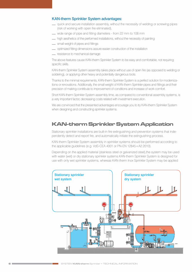
KAN‑therm Sprinkler System ApplicationStationary sprinkler installations are built-in fire extinguishing and prevention systems that inde-pendently detect and report fire, and automatically initiate the extinguishing process.
KAN-therm Sprinkler System assembly in sprinkler systems should be performed according to the applicable guidelines (e.g. VdS-CEA 4001 or PN-EN 12845+A2:2010).
Depending on the applied material (stainless steel or galvanized steel),the system may be used with water (wet) or dry stationary sprinkler systems.KAN-therm Sprinkler System is designed for use with only wet sprinkler systems, whereas KAN-therm Inox Sprinkler System may be applied
Stationary sprinkler wet system
Stationary sprinkler dry system

7ISO 9001
with wet, as well as dry stationary sprinkler systems.
KAN-therm Steel Sprinkler and KAN-therm Inox Sprinkler Systems have been tested and certified according to the VdS guidelines for application in stationary sprinkler installations equipped with emergency valve.
The following guidelines refer to all products comprising KAN-therm Sprinkler System, operating at working pressure stated in the below table:
Operating pressure in KAN-therm Sprinkler System
DN internal ø [mm]VdS
wet [bar] wet and dry (stainless steel) [bar]
20 22 16 16
25 28 16 16
32 35 16 16
40 42 16 16
50 54 16 16
65 76,1 12,5 16
80 88,9 10 12,5
100 108 10 10
Application is limited exclusively to KAN-therm Sprinkler System original elements. Connecting elements other than the original (not included in the KAN-therm Sprinkler System offer) is permissible only on the condition of using detachable metal connections..
Assembly and installation of KAN-therm Sprinkler System may be performed only by qualified technical personnel, having formal qualifications for performing sprinkler system-related works. Requirements regarding assembly of stationary sprinkler installations are included in VdS-CEA 4001 or PN-EN 12845+A2:2010 guidelines. The company performing installation must assure conformity with the above guidelines.
“Press” coupling techniqueThe „Press” coupling technique consists in pressing fittings on the pipe, using specialist power tools.
Tightness of the connections is assured by special O-Ring seals made of EPDM rubber resistant to high temperatures, and „M” type clamping system (O-ring clamped in three spots). This gu-arantees long and reliable operation.
1 2 31. M” type clamp system
2. Joint before pressing
3. Joint after pressing

SYSTEM KAN‑therm Sprinkler • TECHNICAL INFORMATION8
LBP O‑ring sealKAN-therm Sprinkler System pressed fittings are equipped with EPDM O-Rings of the following opera-ting parameters:
Material EPDM LBP (DN20 – DN50) EPDM (DN65 – DN100)
Colour black black
Layer without silicone, Teflon-based without silicone, Teflon-based
Min./Max. temp. -35°C to +135°C -35°C to +135°C
Max. momentary operating press 150°C 150°C
Max. operating pressure16 bar(depending on diameter - check application conditions for a given KAN-therm Sprinkler System)
16 bar(depending on diameter - check application conditions for a given KAN-therm Sprinkler System)
Application range Wet and dry sprinkler systems Wet and dry sprinkler systems
Thanks to special slots of the LBP O-ring body, optimum control of the system during pressure test is assured. The nonpressed joints are easy to locate, as they are not water tight. When pressing, the O-ring changes its shape, adhering entirely to pipe and fitting surface, assuring reliable and tight joint.
KAN-therm Sprinkler System also offers internal threaded elements that are used for connecting threaded elements from outside of the system (not comprising KAN-therm Sprinkler System), such as sprinklers, valves or other fixtures.
Internal and external threads are manufactured in compliance with DIN 2999/ISO 7/1 (taper thread). It is recommended to performthe threaded connection before pressing the fitting, not to stress the pressed joint. To tighten the joint, do not apply Teflon tapes or any other compounds containing chlorides.

9ISO 9001
KAN‑therm System elastic hosesKAN-therm System elastic hoses are covered by approval issued by VdS for stationary sprinkler sys-tems. We offer two versions of hoses, equipped with straight or 90 degree-angled ending. The following dimensions are available: DN20 and DN25 of 800, 1000, 1500 mm lengths.
Elastic hoses designed for fitting in:
— ceiling systems with I-beams, covered with mineral cotton panels and metal cassettes (with fixation to main and auxiliary beams),
— ceiling systems with fixation profiles,
— ceiling systems of gypsum-cardboard panels,
— suspended standard sprinkler systems,
— enclosed sprinklers or sprinklers concealed in cavities.
Assembly of sprinkler lines using stiff pipe conduits in suspended ceilings may be very expensive and time consuming. Use of elastic hoses in sprinkler systems allows for easy and quick connection of sprinklers in any place in the area within the hose’s length. Elastic hoses assure easy assembly of sprin-klers in suspended ceilings, which saves time and costs.
The system comes with assembly holders, which allow for safe and reliable fixture of the sprinkler hose to the suspended ceiling.
The elastic hoes also feature pipe adapters, 100% compatible with KAN-therm Sprinkler. The pipe adapter assures easy connection of the elastic hose to installation performed in KAN-therm Sprinkler system, using Press fittings. In installations using twisted joints, in order to connect the elastic hose with pipe adapter, KAN-therm Sprinkler fitting must be used that has a thread (external/internal) on its one side, and a pressed ending on the other side. After screwing in the fitting,you only need to plug the hose to the pipe adapter and press the joint.
Features — easy and quick assembly using standard KAN-therm Sprinkler, tools
— hose made of stainless steel
— allow for easy assembly in the vicinity of other installation and buildings’ structural elements,
— no need for rotating the entire hose during assembly, thanks to using straight pipe ending,
— freedom of choice at selecting the system fixing the sprinklers along the ceiling plate
— no need for bending or lifting ceiling elements thanks to elastic structure of fixture between sprinkler hose and ceiling
— no need for disassembling and reassembling sprinkler systems during renovations or ceiling replacements. Hoses and holders (together with the installed sprinklers) may be disassembled and reassembled in a new place, without the need of emptying the entire installation (only within the hose length),
— easy vertical setting of the sprinkler thanks to a scale on the sprinkler’s sleeve
SYSTEM KAN‑therm Sprinkler • TECHNICAL INFORMATION10
Elastic hose technical specification
Sprinkler hose Type RS 339L92, DN20/DN25, elastic braided structure, performed entirely of stainless steel, welded joints.
Sprinkler joint (straight)
Stainless steel, pipe thread complying with DIN EN 10226 (ISO 7/1), Rp ½ „(SW 27). Scale for easy vertical set-up Application for installation in limited spaces. Installation height only 170 mm above the lower edge of a suspended ceiling
Sprinkler joint (angular, 90°))
Stainless steel, pipe thread complying with DIN EN 10226 (ISO 7/1), Rp ½ „(SW 27). Scale for easy vertical set-up Application for installation in limited spaces Installation height only 170 mm above the lower edge of a suspended ceiling
Connection adapter Stainless steel, straight ending, 22 or 28 mm diameter for connecting with KAN-therm Sprinkler System connectors
Nominal length 800, 1000, 1500 mm
Max. operating pressure 16 bar, 100% tightness control
Minimum bend radius 70 mm forØ22 hoses; 85 mm for Ø28 hoses
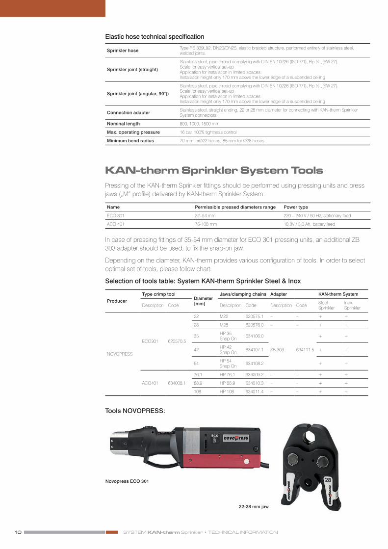
KAN‑therm Sprinkler System ToolsPressing of the KAN-therm Sprinkler fittings should be performed using pressing units and press jaws („M” profile) delivered by KAN-therm Sprinkler System.
Name Permissible pressed diameters range Power type
ECO 301 22–54 mm 220 – 240 V / 50 Hz, stationary feed
ACO 401 76-108 mm 18,0V / 3,0 Ah, battery feed
In case of pressing fittings of 35-54 mm diameter for ECO 301 pressing units, an additional ZB 303 adapter should be used, to fix the snap-on jaw.
Depending on the diameter, KAN-therm provides various configuration of tools. In order to select optimal set of tools, please follow chart:
Selection of tools table: System KAN-therm Sprinkler Steel & Inox
ProducerType crimp tool
Diameter [mm]
Jaws/clamping chains Adapter KAN-therm System
Description Code Description Code Description Code Steel Sprinkler
Inox Sprinkler
NOVOPRESS
ECO301 620570.5
22 M22 620575.1 – – + +
28 M28 620576.0 – – + +
35 HP 35 Snap On 634106.0
ZB 303 634111.5
+ +
42 HP 42 Snap On 634107.1 + +
54 HP 54 Snap On 634108.2 + +
ACO401 634008.1
76,1 HP 76,1 634009.2 – – + +
88,9 HP 88,9 634010.3 – – + +
108 HP 108 634011.4 – – + +
Tools NOVOPRESS:
Novopress ECO 301
22-28 mm jaw

11ISO 9001
ACO 401 machine
Press collar HP 35 Snap On Press collar HP 42, HP 54 Snap On
Press collar HP 76,1 – 108
Adapter ZB 303 35-54mm
KAN‑therm Sprinkler System ‑ joints installation
Cutting pipesPipes must be cut perpendicularly to the axis, using pipe cutter. It is acceptable to use other cutting tools such as manual or electrical saw for metal, if perpendicularity of cutting is maintained, and the edges are not damaged. It is not acceptable to break partially cut pipes. Do not use burners or cutting wheel for cutting. While measuring the cutting length, depth of fitting must be considered.
1
1 2

SYSTEM KAN‑therm Sprinkler • TECHNICAL INFORMATION12
BevellingBevelling should be performed using manual or electrical bevelling machine. Bevel the external and internal edge of the cut pipe, so that it does not damage the O-ring. Also, remove all conta-mination from within the pipe, which may increase the risk of corrosion.
Marking the insert depthTo achieve sufficient joint strength, maintain sufficient insert depth (table 1, fig. 1). The sufficient insert distance should be marked on the pipe (or the fitting) with a marker. After performing the pressing, the marking must still be visible just by the fitting’s edge. Appropriate insert depth is crucial for resistance of joint for stretching,after pressing the O-ring,
Tab.1 Pipe insert depth and minimum installation spaces
DN∅ ext.. Insert depth Minimum distance between
twopressed joints Minimum pipe length
[mm × mm] A [mm] dmin [mm] dmin+2×A [mm]
20 22×1,2 21 10 52
25 28×1,2 23/46* 10 62
32 35×1,5 26/52* 10 80
40 42×1,5 30/60* 20 90
50 54×1,5 35/70* 20 90
65 76,1×2,0 55/54* 40 165
80 88,9×2,0 63/64* 50 186
100 108×2,0 77/74* 60 234
* applies to Groove type couplings
ControlBefore the installation, visually inspect the condition and presence of the appropriate O-Ring. Check whether there is no contamination (filings) on the pipe and in the fitting that may damage the sealing when inserting the pipe Also, check if the pipe ending is not deformed and the section is perfectly circular. Make sure that the distance between neighbouring fittings is not smaller than the permissible value (dmin).
Installing pipe and fittingBefore pressing, insert the pipe into the coupling for a marked depth (small rotation is accepta-ble). Applying oils, greases or fats for facilitating the insertion process
2
3 3A
3
4
5
Fig. 3A – A - pipe insert depth, dmin - minimum in-
stallation distance betweenfittings

13ISO 9001
is not allowed (water or soap solution is acceptable - recommended in case of compressed air pressure test)
Non-axial insertion of pipe is not allowed, as it exposes the sealing to damage. In case of simulta-neously installing multiple joints (by inserting pipes into fittings), before pressing each joint, control the insertion depth
Installation distancesDuring the system installation, structure and dimensions of jaws should be considered, minimum installation distances between pipes and structural cavities, basing on values specified in the table and on images, should be maintained.
Tab. 2 Installation distances
DN Ø ext..Fig. A Fig. B Fig. C
a b a b c Pipe stand-off from wall distance [mm]
20 22×1,2 65 25 80 31 35 40
25 28×1,2 75 25 80 31 35 60
32* 35×1,5 115 75 115 75 75 70
40* 42×1,5 120 75 115 75 75 70
50* 54×1,5 200 85 120 85 85 70
65* 76,1×2,0 250 170 200 170 190 80
80* 88,9×2,0 250 170 250 170 210 90
100* 108×2,0 250 170 250 170 210 100
*applies to snap-on jaws
4 5
A B C

SYSTEM KAN‑therm Sprinkler • TECHNICAL INFORMATION14
PressingBefore pressing, prepare all tools and check for contamination. Press jaw size should always be adjusted to the diameter of the performed joint. Press jaw should be applied on the coupling in such way that its cavity precisely covers the convex section of the fitting (place of putting the O-ring on the fitting) After running the pressing unit, the pressing takes place automatically and may not be stopped. If, for any reason, the pressing is stopped, the joint must be disassembled (cut out) and a new one should be performed. Non-pressed joints, thanks to the special O-ring structure (LBP function) will be signalled already during filling the system with water. After locating the leak, just perform the pressing.
Pipe bending (for diameters up to Ø28)If needed, „cold” bending may be performed, on the condition of maintaining minimum bend radius Rmin:
Rmin ≥ 3,5 × D
For bending pipes, use manual, hydraulic or electrical bender The pipes should not be „hot” bent.
Twisted jointsKAN-therm Sprinkler system also includes external and internal thread elements, which serve the purpose of connecting other threaded elements of the system (such as sprinklers, valves or other). External and internal threads are manufactured according to DIN 2999/ISO 7/1 (taper thread) It is recommended to perform the screwed connection before pressing the fitting, not to stress the pressed joint.
General information regarding system installation
Fitting pipelinesWhile installing KAN-therm Sprinkler System, care must be taken not to overstress the pipelines network, while standby, as well as during an emergency. A/C channels or cable racks should not be placed above the sprinkler pipe.
In case if design or structural reasons make it impossible to avoid the sprinkler pipe crossing other system elements, such as
A/C channels or cable racks, the sprinkler system should be secured from overstressing, using
6
6
15ISO 9001
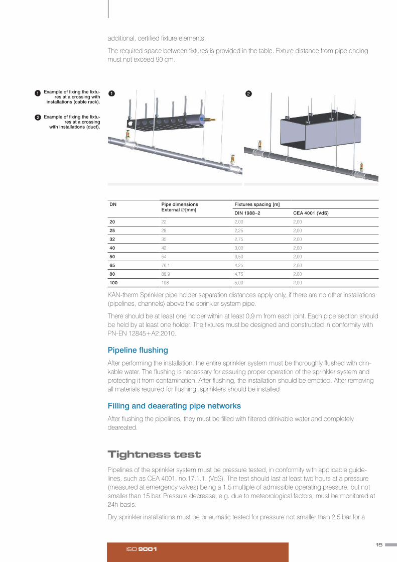
additional, certified fixture elements.
The required space between fixtures is provided in the table. Fixture distance from pipe ending must not exceed 90 cm.
DN Pipe dimensions External ∅[mm]
Fixtures spacing [m]
DIN 1988–2 CEA 4001 (VdS)
20 22 2,00 2,00
25 28 2,25 2,00
32 35 2,75 2,00
40 42 3,00 2,00
50 54 3,50 2,00
65 76,1 4,25 2,00
80 88,9 4,75 2,00
100 108 5,00 2,00
KAN-therm Sprinkler pipe holder separation distances apply only, if there are no other installations (pipelines, channels) above the sprinkler system pipe.
There should be at least one holder within at least 0,9 m from each joint. Each pipe section should be held by at least one holder. The fixtures must be designed and constructed in conformity with PN-EN 12845+A2:2010.
Pipeline flushingAfter performing the installation, the entire sprinkler system must be thoroughly flushed with drin-kable water. The flushing is necessary for assuring proper operation of the sprinkler system and protecting it from contamination. After flushing, the installation should be emptied. After removing all materials required for flushing, sprinklers should be installed.
Filling and deaerating pipe networksAfter flushing the pipelines, they must be filled with filtered drinkable water and completely deareated.
Tightness testPipelines of the sprinkler system must be pressure tested, in conformity with applicable guide-lines, such as CEA 4001, no.17.1.1. (VdS). The test should last at least two hours at a pressure (measured at emergency valves) being a 1,5 multiple of admissible operating pressure, but not smaller than 15 bar. Pressure decrease, e.g. due to meteorological factors, must be monitored at 24h basis.
Dry sprinkler installations must be pneumatic tested for pressure not smaller than 2,5 bar for a
Example of fixing the fixtu-res at a crossing with
installations (cable rack).
Example of fixing the fixtu-res at a crossing
with installations (duct).
2
21 1

SYSTEM KAN‑therm Sprinkler • TECHNICAL INFORMATION16
period of at least 24 hours. Each leak that causes a decrease of pressure greater than 0,15 bar for a period of at least 24 h, must be sealed. All detected defects, such as permanent deformations, breaks or leaks must be fixed and be tested again.
Transport and storageWhen transporting and storing KAN-therm Sprinkler System pipes and pressed fittings, they sho-uld be kept away from damage or contamination hazards.
KAN-therm Sprinkler System elements should not be stored together with elements of other metal systems.
It is not allowed to store system elements directly on the ground (concrete or earth).
It is not allowed to store the elements in direct vicinity of chemical compounds.
Pipe bundles should be stored and transported on wooden or plastic pads (avoid direct contact with other steel elements, such as steel pipe racks).
To avoid ovalization of pipes, it is recommended to form piles not higher than 6 bundles. During transport, loading and unloading, avoid scratching or else mechanically damaging pipes and fittings - do not: throw, pull and bend.
Rooms for storing the elements must be dry (maximum permissible relative humidity must not exceed 65%). Recommended temperature for storage is within 10 to 25 dgr. C.
External pipe surfaces during storage, construction and operation must not be exposed to exten-sive and direct contact with humidity.
General hydraulic dimensioning guidelines for KAN‑therm Sprinkler systems
Pressure lossesTo calculate pressure loss in pipe network of sprinkler systems, Hazen-Williams formula should be applied.
p= ×Q1,85×L6,05×105
C1,85×d4,87
where:
p – linear pressure loss [bar]] Q – flow intensity [l/min] d – internal pipe diameter C – pipe constant, for KAN-therm Steel and Inox Sprinkler systems C=140 L – substitute length for pipes and fittings [m]
The formula covers linear losses on the length of the calculated section of the pipelines, as well as local losses in form of equivalent (substitute) lengths for fittings and fixtures (values of substitute lengths for fittings are shown in table below).
Designing and hydraulic dimensioning principles for sprinkler systems is defined by PN-EN 12845+A2:2010 standard. Stationary fire extinguishing units. Automatic sprinkler systems. Design, assembly and maintenance.

17ISO 9001
∅22 – 54 mm
Local resistance coefficients ζ
ζ 1,5 0,7 0,5 0,5 0,4 0,9 1,3 1,5 3,0
Equivalent lengths of fittings [m]
22 1,40 0,60 0,50 0,50 0,40 0,80 1,20 1,40 2,80
28 1,90 0,90 0,60 0,60 0,50 1,10 1,50 1,90 3,80
35 2,50 1,20 0,80 0,80 0,70 1,50 2,10 2,50 5,00
42 3,10 1,40 1,00 1,00 0,90 1,80 2,60 3,10 6,20
54 4,00 1,80 1,30 1,30 1,10 2,30 3,30 4,00 8,00
∅ 76,1- 108 mm local resistance coefficient ζ
1,3 0,6 0,4 0,5 0,1 1,0 1,3 1,5 3,0
Equivalent lengths of fittings [m]
76,1 6,10 2,80 1,90 2,40 0,50 4,70 6,10 7,10 14,20
88,9 7,80 3,60 2,40 3,00 0,60 6,00 7,80 9,00 18,0
108 10,6 4,90 3,30 4,10 0,80 8,20 10,60 12,30 24,60
Length (mm) Sprinkler joint type
Sprinkler connector
Outside ø (mm) Pressure losses* (bar)
Equiv. pipe length*(m)
1000 straight Rp ½” Ø22 0,9 8
1500 straight Rp ½” Ø22 1,3 12
1000 straight Rp ½” Ø28 0,5 8
1500 straight Rp ½” Ø28 0,8 11
800 degree 90° Rp ½” Ø22 0,8 8
1000 degree 90° Rp ½” Ø22 0,9 8
1500 degree 90° Rp ½” Ø22 1,3 12
800 degree 90° Rp ½” Ø28 0,5 8
1000 degree 90° Rp ½” Ø28 0,5 8
1500 degree 90° Rp ½” Ø28 0,8 11
Tab 3. Pressure losses in elastic hoses and equivalent pipe lengths corresponding to VdS specifications

SYSTEM KAN‑therm Sprinkler • TECHNICAL INFORMATION18
ISO 9001
Technical information.Pricelist
Safety for years to come
SYSTEM KAN‑therm
Steel Sprinkler
TECHNOLOGY OF SUCCESS

SYSTEM KAN‑therm Steel Sprinkler • INFORMACJA TECHNICZNA20

21ISO 9001
Application and operating conditionsKAN-therm Inox Sprinkler System is designed for constructing pipelines (distributing or splitting conduits) of stationary air or water sprinkler systems installed in small or medium fire hazard areas (LH, OH1, OH2, OH3 and up to OH 4 - in reference to exhibition rooms, theatres and concert halls) (according to VdS CEA 4001 guidelines)
Application in other fire extinguishing systems and dry sprinkler systems is prohibited.
The system’s pipes and fittings are approved by the CNBOP (Fire Protection Science and Research Center) with AT-1106- 0227/2009 ID and VdS certificate.
The installation should be designed and constructed according to guidelines included in this document, as well as with applicable standards and regulations.
Designing, assembly and commissioning of the sprinkler system is defined by PN-EN 12845:2008 standard. Stationary fire extinguishing units. Automatic sprinkler units Design, assem-bly and maintenance
Maximum operating pressure of the pipes and fittings is:
— for 22 - 54 diameters 16,0 bar
— for 76,1 diameter 12,5 bar
— for 88,9 and 108 diameter 10,0 bar.

SYSTEM KAN‑therm Steel Sprinkler • INFORMACJA TECHNICZNA22
System KAN‑therm Steel Sprinkler ‑ carbon steel pipes
KAN-therm Steel Sprinkler System pipes for water sprinkler installations are precise carbon steel no. 1.0031 (EN10305-3 compliant) pipes. They are made of cold rolled strip, galvanized using the Sendzimir method of coating the metal plate with zinc by immersing it in electrolytic zinc, after which the zinc is applied on both sides simultaneously. This means the pipe is protected by zinc layer on inside and outside. The zinc layer is never less than 20 μm thick. The Sendzimir galvani-zation is known for guaranteeing particularly good adherence and high resistance to corrosion.
Fire environment propertiesKAN-therm Steel Sprinkler System carbon steel pipes may be classified as class A incombustible materials, according to DIn 4102, part 1.
Technical details of pipes
DN Outside diameter x wall thickness
Inside diameter Unit mass Water capacity
mm × mm [mm] [kg/m] [kg/m]
20 22 × 1,5 19,0 0,761 0,284
25 28 × 1,5 25,0 0,980 0,491
32 35 × 1,5 32,0 1,241 0,804
40 42 × 1,5 39,0 1,542 1,195
50 54 × 1,5 51,0 1,999 2,043
65 76,1 × 2,0 72,1 3,503 4,083
80 88,9 × 2,0 84,9 4,412 5,661
100 108 × 2,0 104,0 5,382 8,495
23ISO 9001
KAN-therm Steel Sprinkler for sprinkler systems pipe dimensions
Material ULC („Ultra Light Carbon”) galvanized (Sendzimir method) material no. 1.0031 acc. to EN 10305-3
Outside diameter tolerance acc. to EN10305-3
Thermal expansion coefficient 0,0108 mm/m at ∆T= 1KK
Minimum bend radius (for diameters up to Ø28 mm) 3,5 x pipe outside diameter (up to -10°C)
Delivery 6 m ± 50 mm lengths
Marking name or manufacturer label, material identification outside diameter x wall thickness, approval no., manufacture date
Zinc layer at least 20 μm. The pipe joints are extra galvanized.
Max. operating pressure 16 bar (22-54 mm); 12,5 bar (76,1 mm); 10 bar (88,9-108 mm)
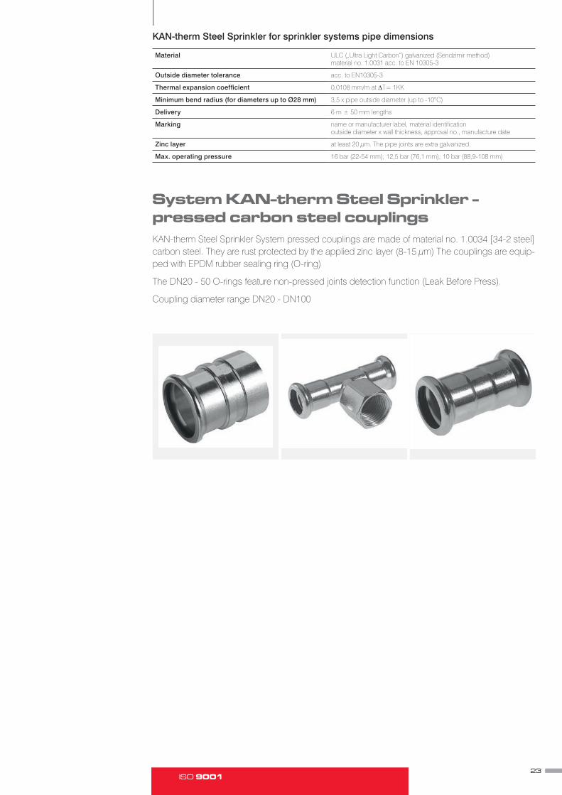
System KAN‑therm Steel Sprinkler ‑ pressed carbon steel couplingsKAN-therm Steel Sprinkler System pressed couplings are made of material no. 1.0034 [34-2 steel] carbon steel. They are rust protected by the applied zinc layer (8-15 μm) The couplings are equip-ped with EPDM rubber sealing ring (O-ring)
The DN20 - 50 O-rings feature non-pressed joints detection function (Leak Before Press).
Coupling diameter range DN20 - DN100

SYSTEM KAN‑therm Steel Sprinkler • INFORMACJA TECHNICZNA
* on request – (delivery time up to 4 weeks) | ** availability by individual arrangements | *** till stock ends
24
System KAN‑therm Steel Sprinkler ‑ assortmentpress carbon steel pipe, zinc coated GROUP: J
Size * Code Pcs. Ilość m w op. zbiorczych
22×1,5 6241114S bar 6m 6/360
28×1,5 6241125S bar 6m 6/300
35×1,5 6241136S bar 6m 6/180
42×1,5 6241147S bar 6m 6/150
54×1,5 6241158S bar 6m 6/90
76,1×2 6241378S bar 6m 6/-
88,9×2 6241389S bar 6m 6/-
108×2 6241391S bar 6m 6/-
press male connector GROUP: I
Size l z * Code Pcs. /packing
22×R½ 43 22 6241015S 6241015S
22×R¾ 44 23 6240135S 6240135S
22×R1 50 29 6241026S 6241026S
28×R¾ 46 23 6249852S 6249852S
28×R1 48 25 6240146S 6240146S
35×R1 53 27 6341247S 6341247S
35×R1¼ 55 29 6240157S 6240157S
42×R1½ 59 29 6240168S 6240168S
54×R2 69 34 6240179S 6240179S
76,1×R2½ 123 68 ** 6302823S 6302823S
88,9×R3 134 71 ** 6302825S 6302825S
press male union connector GROUP: I
Size l z * Code Pcs. /packing
22×R¾ 70 49,0 6240916S 2/40
28×R1 74,7 51,7 6240927S 2/30
35×R1¼ 81,8 55,8 6240938S 2/20
42×R1½ 88 58,0 6240949S 2/16
54×R2 100 65,0 6240951S 2/10
press half union GROUP: I
Size l z * Code Pcs. /packing
22×G1 32 11 ** 6340554S 10/60
28×G1¼ 33 10 ** 6340565S 10/40
35×G1½ 36 10 ** 6340576S 4/32
42×G1¾ 43 13 ** 6340587S 4/12
54×G2 3/8 50 15 ** 6340598S 4/8

25ISO 9001
* on request – (delivery time up to 4 weeks) | ** availability by individual arrangements | *** till stock ends
press female connector GROUP: I
Size l z * Code Pcs. /packing
22×Rp½ 36,5 4,5 6302708S 10/100
22×Rp¾ 43 5,7 6240102S 10/100
28×Rp½ 38 2 6240113S 10/60
28×Rp¾ 40,5 1 6249830S 10/60
28×Rp1 49 7 6240124S 10/60
35×Rp½ 42 5,3 ** 6340917S 10/40
35×Rp1¾ 43 5,2 ** 6340928S 10/40
35×Rp1 46 7 ** 6340939S 10/40
35×Rp1¼ 50 2,3 6241004S 10/30
42×Rp1½ 54 2 6302721S 10/40
54×Rp2 63 2 6302723S 10/40
press nipple female connector GROUP: I
Size A Z D * Code Pcs. /packing
22×Rp½ 50 35,0 22 6240960S 10/70
22×Rp¾ 53 36,7 22 6240971S 10/100
press coupling GROUP: I
Size l z * Code Pcs. /packing
22×22 55 13 6240003S 10/80
28×28 59 13 6240014S 10/60
35×35 65 13 6240025S 10/40
42×42 76 16 6240036S 4/24
54×54 86 16 6240047S 4/16
76,1×76,1 142 28 6206200S 2/-
88,9×88,9 160 34 6206211S 2/-
108×108 199 41 6206222S 2/-
press slip coupling GROUP: I
Size l z * Code Pcs. /packing
22×22 84 25 6240058S 10/60
28×28 91 30 6240069S 10/40
35×35 102 30 6240071S 10/20
42×42 120 40 6240080S 4/16
54×54 140 40 6240091S 4/8
76,1×76,1 230 60 6206233S 2/-
88,9×88,9 262 70 6206244S 2/-
108×108 304 80 6206255S 2/-

SYSTEM KAN‑therm Steel Sprinkler • INFORMACJA TECHNICZNA
* on request – (delivery time up to 4 weeks) | ** availability by individual arrangements | *** till stock ends
26
press 90° elbow GROUP: I
Size l z * Code Pcs. /packing
22×22 51 30 6240181S 10/60
28×28 60 37 6240190S 10/30
35×35 71 45 6240201S 10/10
42×42 86 56 6240212S 2/16
54×54 105 70 6240223S 2/8
76,1×76,1 150 95 6208004S 2/-
88,9×88,9 174 111 6208048S 2/-
108×108 215 139 6208059S 2/-
press nipple 90° elbow GROUP: I
Size l z h * Code Pcs. /packing
22×22 51 30 58,1 6240410S 10/60
28×28 60 37 65,5 6240421S 10/30
35×35 71 45 75,9 6240432S 10/10
42×42 86 56 92,5 6240443S 2/8
54×54 105 70 110,6 6240454S 2/6
76,1×76,1 150 94 166 6208061S 2/-
88,9×88,9 174 109 190 6208070S 4/-
108×108 215 122 230 6208081S 4/-
press 45° elbow GROUP: I
Size l z * Code Pcs. /packing
22×22 35,2 14,2 6240511S 10/70
28×28 40,1 17,1 6240520S 10/40
35×35 46,4 20,4 6240531S 5/25
42×42 56,1 26,1 6240542S 2/16
54×54 66,9 31,9 6240553S 2/8
76,1×76,1 98 43 6208125S 4/-
88,9×88,9 113 50 6208136S 4/-
108×108 138 62 6208147S 2/-
press nipple 45° elbow GROUP: I
Size l z h * Code Pcs. /packing
22×22 35,2 14,2 42,3 6240465S 10/60
28×28 40,1 17,1 45,6 6240476S 10/40
35×35 46,4 20,4 51,3 6240487S 5/25
42×42 56,1 26,1 62,6 6240498S 4/16
54×54 66,9 31,9 72,5 6240509S 2/8
76,1×76,1 96 41 119 6208092S 2/-
88,9×88,9 110 47 130 6208103S 2/-
108×108 137 61 160 6208114S 2/-

27ISO 9001
* on request – (delivery time up to 4 weeks) | ** availability by individual arrangements | *** till stock ends
press tee GROUP: I
Size l1 z1 l2 z2 * Code Pcs. /packing
22×22×22 39,5 18,5 48,5 27,5 6240564S 10/40
28×28×28 44,5 21,5 53,5 30,5 6240575S 10/30
35×35×35 51 25 60 34 6240586S 5/15
42×42×42 60 30 66,5 36,5 6240597S 4/8
54×54×54 71 36 77,5 42,5 6240608S 2/6
76,1×76,1×76,1 116 61 121 61 6206442S 2/-
88,9×88,9×88,9 131 68 126 63 6206453S 2/-
108×108×108 152,0 78 152 74 6206464S 2/-
press reducing tee GROUP: I
Size l1 z1 l2 z2 * Code Pcs. /packing
22×28×22 39,5 18,5 52 29 6240718S 10/40
28×22×28 44,5 21,5 51,5 30,5 6240729S 10/30
35×22×35 51 25 55 34 6240731S 5/20
35×28×35 51 25 57 34 6240740S 10/20
42×22×42 60 30 57,5 36,5 6240751S 4/12
42×28×42 60 30 59,5 36,5 6240762S 4/12
42×35×42 60 30 62,5 36,5 6240773S 4/12
54×22×54 71 36 63,5 42,5 6240784S 2/8
54×28×54 71 36 65,5 42,5 6240795S 2/8
54×35×54 71 36 68,5 42,5 6240806S 2/8
54×42×54 71 36 72,5 42,5 6240817S 2/8
76,1×22×76,1 116 61 79 47 ** 6303371S 2/-
76,1×28×76,1 116 61 80 43 ** 6303373S 2/-
76,1×35×76,1 131 68 75,5 51,5 ** 6303375S 2/-
76,1×42×76,1 131 68 83 56,5 ** 6303377S 2/-
76,1×54×76,1 131 68 85 53 6206475S 2/-
88,9×22×88,9 131 68 92,5 55,5 ** 6303379S 2/-
88,9×28×88,9 131 68 128 73 ** 6303381S 2/-
88,9×35×88,9 156 78 135 72 ** 6303383S 2/-
88,9×42×88,9 156 78 85 62 ** 6303385S 2/-
88,9×54×88,9 156 78 87,5 63,5 ** 6303387S 2/-
88,9×76,1×88,9 156 78 93,5 66 6206486S 2/-
108×22×108 156 78 96 64 ** 6303389S 2/-
108×28×108 156 78 102 65 ** 6303391S 2/-
108×35×108 156 78 125 70 ** 6303393S 2/-
108×42×108 131 68 76 53 ** 6303395S 2/-
108×54×108 116 61 68 45 ** 6303397S 2/-
108×76,1×108 116 61 71 47 ** 6303399S 2/-
108×88,9×108 116 61 75 48 6206497S 2/-

SYSTEM KAN‑therm Steel Sprinkler • INFORMACJA TECHNICZNA
* on request – (delivery time up to 4 weeks) | ** availability by individual arrangements | *** till stock ends
28
press pipe cross 90º GROUP: I
Size h l1 z1 l2 z2 * Code Pcs. /packing
28×22×22×28 31 22 19 45 40 6240828S 10/20
press crossing GROUP: I
Size l1 z1 l2 z2 * Code Pcs. /packing
35×35×35×35 51,5 60 25,3 33,8 ** 6340972S 2/8
42×42×42×42 60,7 66,5 30,4 36,3 ** 6340983S 2/8
54×54×54×54 71 77,5 36 42,5 ** 6340994S -/4
35×28×35×28 51,5 57 25,3 33,7 ** 6341005S 2/14
42×28×42×28 60,7 59,5 30,4 36,2 ** 6341016S 2/8
54×28×54×28 71 65,5 36 42,2 ** 6341027S -/4
press nipple reducer GROUP: I
Size l z d1 d2 * Code Pcs. /packing
28×22 63 42 28 22 6240234S 10/80
35×22 68 47 35 22 6240245S 10/50
35×28 69 46 35 28 6240256S 10/60
42×22 80 59 42 22 6246651S 5/30
42×28 79 56 42 28 6240267S 5/30
42×35 76 50 42 35 6240278S 4/24
54×22 89 68 54 22 6240289S 4/16
54×28 87 64 54 28 6240291S 4/16
54×35 89 63 54 35 6240300S 10/30
54×42 91 61 54 42 6240993S 4/16
76,1×42 151 121 76,1 42 6206387S 2/-
76,1×54 145 109 76,1 54 6206398S 2/-
88,9×54 157 122 88,9 54 6206409S 2/-
88,9×76,1 157 105 88,9 76,1 6206411S 2/-
108×76,1 196 144 108 76,1 6206420S 2/-
108×88,9 192 133 108 88,9 6206431S 2/-

29ISO 9001
* on request – (delivery time up to 4 weeks) | ** availability by individual arrangements | *** till stock ends
press male elbow GROUP: I
Size b z a * Code Pcs. /packing
22×R¾ 61,5 30 51 6240366S 10/60
28×R1 73,5 37 60 6240377S 10/30
35×R1¼ 85,5 45 71 6240388S 10/10
42×R1½ 95,5 56 86 6240399S 4/12
54×R2 115,5 70 105 6240401S 2/8
press male elbow - short GROUP: I
Size l2 z l1 * Code Pcs. /packing
22×R¾ 44,5 23,5 32 6240982S 10/60
press female elbow 90° GROUP: I
Size l2 z l1 * Code Pcs. /packing
22×Rp½ 59 30 51 6249577S 10/30
22×Rp¾ 59 30 51 6240964S 10/30
28×Rp½ 65 37 60 6241169S 5/30
28×Rp¾ 65 37 60 6241171S 5/30
28×Rp1 69,5 37 60 6249588S 5/30
35×Rp½ 74,5 45 71 6241180S 5/10
35×Rp¾ 74,5 45 71 6241061S 5/10
35×Rp1 74,5 45 71 6249599S 5/10
press female elbow - short GROUP: I
Size l1 l2 z1 z2 * Code Pcs. /packing
22×Rp½ 31 44,5 16 23 ** 6340972S 10/50
28×Rp½ 35 50,5 20 26,7 ** 6340983S 5/30
35×Rp½ 35 56,5 20 29,4 ** 6340994S 5/10

SYSTEM KAN‑therm Steel Sprinkler • INFORMACJA TECHNICZNA
* on request – (delivery time up to 4 weeks) | ** availability by individual arrangements | *** till stock ends
30
press female tee GROUP: I
Size l1 z1 l2 z2 * Code Pcs. /packing
22×Rp½×22 39,5 18,5 39 24 6240619S 10/50
22×Rp¾×22 39,5 18,5 41 24,7 6240621S 10/40
28×Rp½×28 44,5 21,5 42 27 6240630S 10/30
28×Rp¾×28 44,5 21,5 44 27,7 6240641S 10/30
28×Rp1×28 44,5 21,5 46 27,5 6249601S 10/30
35×Rp½×35 51 25 45,5 30,5 6240652S 10/20
35×Rp¾×35 51 25 47,5 31,2 6240663S 10/20
35×Rp1×35 51 25 50 31 6249610S 10/20
42×Rp½×42 60 30 48 33 6240674S 4/16
42×Rp¾×42 60 30 50 33,7 6240685S 4/16
42×Rp1×42 60 30 52,5 33,5 6249621S 4/16
54×Rp½×54 71 36 54 39 6240696S 2/8
54×Rp¾×54 71 36 56 39,7 6240707S 2/8
54×Rp1×54 71 36 60 41 6241070S 2/8
76,1×Rp¾×76,1 116 61 69 52 6206508S 2/-
88,9×Rp¾×88,9 131 68 76 59 6206519S 1/-
108×Rp¾×108 156 78 86 69 6206521S 1/-
crossover GROUP: I
Size l a b * Code Pcs. /packing
22×22 64,5 177 37 6240883S 10/50
28×28 75 215 43 6240894S 10/20
bend 90° GROUP: I
Size l1 z1 l2 z2 * Code Pcs. /packing
22×22 72 70 120 70 6240839S 10/40
28×28 82 80 120 80 6240841S 10/20
35×35 120 100 200 100 6240850S 4/8
42×42 150 120 250 120 6240861S 2/4
54×54 200 145 300 145 6240872S 2/2
press flange PN16 GROUP: I
Size DN z d h k b d2 otwory * Code Pcs. /packing
76,1 65 79 185 134 145 18 18 4 620659.6S 4/-
88,9 80 78 200 141 160 20 18 8 620660.7S 2/-
108 100 88 220 166 180 20 18 8 620661.8S 2/-

31ISO 9001
* on request – (delivery time up to 4 weeks) | ** availability by individual arrangements | *** till stock ends
press cup GROUP: I
Size l z * Code Pcs. /packing
22 28,5 7,5 6240311S 10/240
28 32,3 9,3 6240322S 10/130
35 34,4 8,4 6240333S 5/75
42 43,2 13,2 6240344S 4/48
54 51,8 16,8 6240355S 4/32
76,1 70 15 6206915S 4/-
88,9 87 24 6206926S 4/-
108 98 21 6206937S 4/-
groove connector GROUP: I
Size l D Z * Code Pcs. /packing
28×33,7 72,5 33,7 26 ** 624130.1S 10/30
35×42,4 81 42,4 26 ** 624134.5S 10/30
42×48,3 86 48,3 26 ** 624135.6S 5/20
54×60,3 96,5 60,3 26 ** 624136.7S 5/15
76,1×76,1 90 76,1 36 ** 6340774S 2/-
88,9×88,9 100 88,9 36 ** 6340785S 2/-
108×114 110 114,3 36 ** 6340796S 2/-
long press female connector GROUP: I
Size l A B * Code Pcs. /packing
22×Rp½ 92 25 15 ** 624131.2S 10/60
22×Rp¾ 97 25 16 ** 624132.3S 10/60
28×Rp½ 94 30 15 ** 624126.8S 10/40
28×Rp¾ 93 30 16 ** 624127.9S 10/40
O-Ring LBP EPDM GROUP: I
Size * Code Pcs. /packing
22 6222238 20/500
28 6222249 20/400
35 6222251 20/400
42 6222260 20/300
54 6222271 20/300
O-Ring EPDM GROUP: I
Size * Code Pcs. /packing
76,1 620801.5 5/100
88,9 620802.6 5/100
108 620803.7 5/50

SYSTEM KAN‑therm Steel Sprinkler • INFORMACJA TECHNICZNA
* on request – (delivery time up to 4 weeks) | ** availability by individual arrangements | *** till stock ends
32
flexible hose with straight ending GROUP: I
Size długość * Code Pcs. /packing
Rp½”×Ø22 1000 ** 619800.5S -/10
Rp½”×Ø22 1500 ** 619802.7S -/10
Rp½”×Ø22 2000 ** 619803.8S -/10
Rp½”×Ø28 1000 ** 619804.9S -/10
Rp½”×Ø28 1500 ** 619806.0S -/10
Rp½”×Ø28 2000 ** 619807.1S -/10
flexible hose with 90° angle ending GROUP: I
Size długość * Code Pcs. /packing
Rp½”×Ø22 800 ** 619808.2S -/10
Rp½”×Ø22 1000 ** 619809.3S -/10
Rp½”×Ø22 1500 ** 619811.5S -/10
Rp½”×Ø28 800 ** 619813.7S -/10
Rp½”×Ø28 1000 ** 619814.8S -/10
Rp½”×Ø28 1500 ** 619816.1S -/10
All flexible hoses are equipped with mounting bracket: 1 x 700 mm square pipe, 1 x sliding clamp, 2 x multiclip bracket.
cutter for steel pipes GROUP: K
Size * Code Pcs. /packing
15-54 mm 113000 any
35-108 mm 113100 any
wheel for cutter for steel pipes - service element GROUP: K
Size * Code Pcs. /packing
341614 any
electric cutter GROUP: K
Size * Code Pcs. /packing
22-108 mm 845000 any
stripping tool - drill set GROUP: K
Size * Code Pcs. /packing
15-54 mm 113835 any
press machine ECO 301 GROUP: K
Nazwa Dopuszczalny zakres zaciskanych średnic
Typ zasilania [V] * Code Pcs.
/packing
ECO 301 22-54 mm Sieciowe 220-240 620570.5 any
33ISO 9001
* on request – (delivery time up to 4 weeks) | ** availability by individual arrangements | *** till stock ends
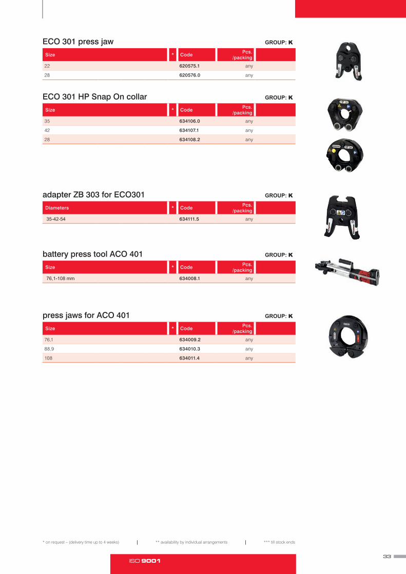
ECO 301 press jaw GROUP: K
Size * Code Pcs. /packing
22 620575.1 any
28 620576.0 any
ECO 301 HP Snap On collar GROUP: K
Size * Code Pcs. /packing
35 634106.0 any
42 634107.1 any
28 634108.2 any
adapter ZB 303 for ECO301 GROUP: K
Diameters * Code Pcs. /packing
35-42-54 634111.5 any
battery press tool ACO 401 GROUP: K
Size * Code Pcs. /packing
76,1-108 mm 634008.1 any
press jaws for ACO 401 GROUP: K
Size * Code Pcs. /packing
76,1 634009.2 any
88,9 634010.3 any
108 634011.4 any

SYSTEM KAN‑therm Steel Sprinkler • INFORMACJA TECHNICZNA34

ISO 9001
Technical information.Pricelist
Safety for years to come
SYSTEM KAN‑therm
Inox Sprinkler
TECHNOLOGY OF SUCCESS

SYSTEM KAN‑therm Inox Sprinkler • INFORMACJA TECHNICZNA36

37ISO 9001
Application and operational conditionsKAN-therm Inox Sprinkler System is designed for constructing pipelines (distributing or splitting conduits) of stationary air or water sprinkler systems installed in small or medium fire hazard areas (LH, OH1, OH2, OH3 and up to OH 4 - inreference to exhibition rooms, theatres and concert halls) (according to VdS CEA 4001 guidelines)
The system’s pipes and fittings are approved by the CNBOP (Fire Protection Science and Research Center) with AT-1106-0249/2009 ID and VdS certificate.
Maximum operating pressure of the pipes and fittings is
— for 22 - 76,1 diameters, 16,0 bar
— for 88,9 diameter 12,5 bar
— for 108 diameter - 10,0 bar
IThe installation should be designed and constructed according to guidelines included in this document, as well as with applicable standards and regulations
Designing, assembly and commissioning of the sprinkler system is defined by PN-EN 12845:2008 standard. Stationary fire extinguishing units. Automatic sprinkler units Design, assembly and maintenance

SYSTEM KAN‑therm Inox Sprinkler • INFORMACJA TECHNICZNA38
System KAN‑therm Inox Sprinkler ‑ stain‑less steel pipes
KAN-therm Inox Sprinkler System pipes for sprinkler systems are precise X5CrNiMo (1.4401 acc. to EN 10088 AISI 316) stainless steel pipes.
KAN-therm Inox Sprinkler System pipes may be classified as A category incombustible materials, acc. to DIN 4102, part 1.
The pipes are distributed in 6 metre lengths. Minimum pipe bend radius 3,5 x D (for DN20 - DN25 diameters).
Pipe technical specification
DN Outside diameter x wall thickness
Inside diameter Unit mass Water capacity
[mm × mm] [mm] [kg/m] [l/m]
20 22 × 1,5 19,6 0,624 0,302
25 28 × 1,5 25,6 0,790 0,515
32 35 × 1,5 32,0 1,240 0,804
40 42 × 1,5 39,0 1,503 1,195
50 54 × 1,5 51,0 1,972 2,043
65 76,1 × 2,0 72,1 3,550 4,548
80 88,9 × 2,0 84,9 4,150 5,661
100 108 × 2,0 104,0 5,050 8,495

39ISO 9001
KAN-therm Inox Sprinkler pipe for sprinkler system dimensions.
Material X5CrNiMo stainless steel material no. 1.4401 acc. to EN 10088-2 (AISI 316)
Outside diameter tolerance EN 10305-3
Thermal expansion coefficient 0,0160 mm/m at ∆T= 1K
Minimum bend radius (for diameters up to Ø28 mm)
3,5 x outside pipe diameter (up to -10°C)
Delivery 6 m ± 50 mm lengths
Marking name or manufacturer label, material identification outside diameter x wall thickness, approval no., manufacture date
Max. operating pressure 16 bar (22-76,1 mm); 12,5 bar (88,9 mm); 10 bar (108 mm)
System KAN‑therm Inox Sprinkler ‑ pressed stainless steel couplingsKAN-therm Inox Sprinkler System pressed couplings are made of stainless steel, material no. 1.4404 acc. to EN 10088. The couplings are equipped with EPDM rubber sealing ring (O-ring).
Coupling diameter range DN20 - DN100

SYSTEM KAN‑therm Inox Sprinkler • INFORMACJA TECHNICZNA
* on request – (delivery time up to 4 weeks) | ** availability by individual arrangements | *** till stock ends
40
System KAN‑therm Inox Sprinkler ‑ assortment
stainless steel pipe GROUP: H
Size * Code Pcs. Packing
22×1,2 611793.6S bar 6m 6/360
28×1,2 611794.7S bar 6m 6/300
35×1,5 611795.8S bar 6m 6/180
42×1,5 611796.9S bar 6m 6/150
54×1,5 611797.1S bar 6m 6/90
76,1×2 611798.0S bar 6m 6/168
88,9×2 611799.1S bar 6m 6/136
108×2 611800.2S bar 6m 6/108
press male connector GROUP: G
Size l z * Code Packing
22×R½ 42 21 6190635S 10/70
22×R¾ 43,3 22,3 6190646S 10/100
22×R1 48,5 27,5 6190624S 10/60
28×R¾ 45,2 22,2 6190679S 10/50
28×R1 48 25 6190657S 10/60
28×R1¼ 51,5 28,5 6190668S 10/30
35×R1 52,7 26,7 6190681S 10/40
35×R1¼ 55 29 6190701S 5/40
35×R1½ 56 30 6190690S 10/20
42×R1¼ 59 29 6190723S 4/12
42×R1½ 59 29 6190712S 4/24
54×R1½ 64,7 29,7 6190734S 4/16
54×R2 69 34 6190745S 4/12
76,1×R2½ 125 70 620475.9S 2/-
88,9×R3 138 75 620476.1S 2/-
press union connector GROUP: G
Size l z * Code Packing.
22×R½ 63 42 6192164S 2/40
22×R¾ 68,5 47,5 6192175S 2/40
22×R1 71,8 50,8 6192186S 2/30
28×R1 72,8 49,8 6192197S 2/30
35×R1¼ 78,2 52,2 6192208S 2/16
42×R1½ 85,4 55,4 6192219S 2/12
54×R2 100 65 6192296S 2/4

41ISO 9001
* on request – (delivery time up to 4 weeks) | ** availability by individual arrangements | *** till stock ends
press female connector GROUP: G
Size l z * Code Packing
22×Rp½ 36,5 5,5 6190461S 10/100
22×Rp¾ 39,5 7,5 6190470S 10/100
22×Rp1 43,6 9,6 6190459S 10/60
28×Rp½ 38 3 6193308S 10/40
28×Rp¾ 40 6 6190503S 10/40
28×Rp1 44,6 8,6 6190481S 10/60
28×Rp1¼ 47 9 6190492S 10/30
35×Rp1 46 7 6190514S 10/20
35×Rp1¼ 50 9 6190536S 10/30
35×Rp1½ 50 10 6190525S 10/20
42×Rp1¼ 52 3 6190558S 4/12
42×Rp1½ 54 10 6190547S 4/24
54×Rp1½ 58 9 6190569S 4/12
54×Rp2 63 10 6190571S 4/12
press female union connector GROUP: G
Size l z * Code Packing
22×Rp¾ 63 25,5 6192065S 2/40
22×Rp1 65,8 25,3 6192076S 2/30
28×Rp1 65 22,5 6192087S 2/26
35×Rp1¼ 73 25,3 6192098S 1/20
42×Rp1½ 82 30 6192109S 2/8
54×Rp2 91 30 6192111S 2/4
press half union connector (with flat gasket) GROUP: G
Size l z * Code Packing.
22×Rp¾ 11 11 6191757S 10/60
22×Rp1 10 10 6191768S 10/40
28×Rp1 10 10 6191779S 4/32
35×Rp1¼ 13 13 6191781S 4/12
42×Rp1½ 15 15 6191790S 4/8
54×Rp2 36,7 22 6240971S 10/100
press coupling GROUP: G
Size l z * Code Packing
22×22 52 10 6190965S 10/80
28×28 56,2 10,2 6190976S 10/60
35×35 62,3 10,3 6190987S 5/40
42×42 73,3 13,3 6190998S 4/24
54×54 83 13 6191009S 4/16
76,1×76,1 142 32 620415.4S 4/-
88,9×88,9 163 37 620416.5S 4/-
108×108 192 38 620417.6S 4/-

SYSTEM KAN‑therm Inox Sprinkler • INFORMACJA TECHNICZNA
* on request – (delivery time up to 4 weeks) | ** availability by individual arrangements | *** till stock ends
42
press slip coupling GROUP: G
Size l z * Code Packing
22×22 84 21 6191306S 10/60
28×28 91,2 23 6191317S 10/40
35×35 102,2 26 6191328S 5/20
42×42 120,3 30 6191339S 4/16
54×54 140 35 6191341S 2/8
76,1×76,1 230 60 620428.6S 2/-
88,9×88,9 258 70 620429.7S 2/-
108×108 305 80 620430.8S 2/-
press 90° elbow GROUP: G
Size l z * Code Packing
22×22 51 30 6190228S 10/60
28×28 60,1 37,1 6190239S 5/30
35×35 71,1 45,1 6190241S 5/20
42×42 86,1 56,1 6190250S 2/8
54×54 105 70 6190261S 2/8
76,1×76,1 150 95 6230004S 2/-
88,9×88,9 175 112 6230015S 2/-
108×108 214 137 6230026S 1/-
press nipple 90° elbow GROUP: G
Size l z h * Code Packing
22×22 51 30 60 6190360S 5/60
28×28 60,1 37,1 65,5 6190371S 5/30
35×35 71,1 45,1 75,9 6190382S 5/10
42×42 86,1 56,1 92,5 6190393S 2/8
54×54 105 70 110,6 6190404S 2/6
76,1×76,1 150 95 165 6230037S 1/-
88,9×88,9 174 110 190 6230048S 1/-
108×108 216 137 238 6230059S 1/-
KAN-therm press 45° elbow GROUP: G
Size l z * Code Packing
22×22 35,2 14,2 6190063S 10/70
28×28 40,2 17,2 6190074S 10/40
35×35 46,5 20,5 6190085S 5/25
42×42 56,3 26,3 6190096S 2/16
54×54 66,9 31,9 6190107S 2/8
76,1×76,1 98 43 6230061S 2/-
88,9×88,9 112 49 6230070S 2/-
108×108 138 61 6230081S 2/-

43ISO 9001
* on request – (delivery time up to 4 weeks) | ** availability by individual arrangements | *** till stock ends
press nipple 45° elbow GROUP: G
Size l z ? * Code Packing
22×22 35,2 14,2 ? 6190131S 10/70
28×28 40,2 17,2 6190140S 10/40
35×35 46,5 20,5 6190151S 5/25
42×42 56,3 26,3 6190162S 2/16
54×54 66,9 31,9 6190173S 2/8
76,1×76,1 98 43 6230092S 2/-
88,9×88,9 112 49 6230103S 2/-
108×108 138 61 6230114S 2/-
press tee GROUP: G
Size l1 z1 l2 z2 * Code Packing
22×22x22 39,5 18,5 43,5 22,5 6191405S 10/40
28×28x28 44,5 21,5 48,5 25,5 6191449S 5/25
35×35x35 51 25 55 29 6191493S 5/15
42×42x42 60 30 61,5 31,5 6191537S 4/8
54×54x54 71 36 72,5 37,5 6191581S 2/6
76,1×76,1×76,1 116 61 115 60 620431.9S 2/-
88,9×88,9×88,9 131 68 127 64 620432.1S 2/-
108×108×108 156 79 155 78 620433.0S 2/-

SYSTEM KAN‑therm Inox Sprinkler • INFORMACJA TECHNICZNA
* on request – (delivery time up to 4 weeks) | ** availability by individual arrangements | *** till stock ends
44
press tee GROUP: G
Size l1 z1 l2 z2 * Code Packing
28×22×28 46 23 45 24 6191438S 10/30
35×22×35 51 25 50 29 6191471S 5/20
35×28×35 51 25 52 29 6191482S 5/20
42×22×42 60 30 52,5 31,5 6191504S 4/12
42×28×42 60 30 54,5 31,5 6191515S 4/12
42×35×42 60 30 57,5 31,5 6191526S 4/12
54×22×54 71 36 58,5 37,5 6191548S 2/8
54×28×54 71 36 60,5 37,5 6191559S 2/8
54×35×54 71 36 63,5 37,5 6191561S 2/8
54×42×54 71 36 67,5 37,5 6191570S 2/8
76,1×22×76,1 116 61 68 45 620434.1S 2/-
76,1×28×76,1 116 61 71 47 ** 620435.2S 2/-
76,1×35×76,1 116 61 75 48 ** 620436.3S 2/-
76,1×42×76,1 116 61 79 47 ** 620437.4S 2/-
76,1×54×76,1 116 61 80 43 ** 620438.5S 2/-
88,9×22×88,9 131 68 76 53 620439.6S 2/-
88,9×28×88,9 131 68 76 52 ** 620440.7S 2/-
88,9×35×88,9 131 68 83 56 ** 620441.8S 2/-
88,9×42×88,9 131 68 85 53 ** 620442.9S 2/-
88,9×54×88,9 131 68 93 56 ** 620443.1S 2/-
88,9×76,1×88,9 131 68 116 61 ** 620444.0S 2/-
108×22×108 156 79 85 62 620445.1S 2/-
108×28×108 156 79 88 64 ** 620446.2S 2/-
108×35×108 156 79 94 67 ** 620447.3S 2/-
108×42×108 156 79 96 64 ** 620448.4S 2/-
108×54×108 156 79 102 65 ** 620449.5S 2/-
108×76,1×108 156 79 125 70 ** 620450.6S 2/-
108×88,9×108 156 79 135 72 620451.7S 2/-
press nipple reducer GROUP: I
Size l z d1 d2 * Code Packing
28×22 61,2 40,2 28 22 6191174S 10/80
35×22 69 48 35 22 6191196S 5/50
35×28 68,1 45,1 35 28 6191207S 5/60
42×22 84,5 63,5 42 22 6191218S 4/24
42×28 77,9 54,9 42 28 6191229S 4/24
42×35 77,6 51,6 42 35 6191231S 4/24
54×22 96,5 75,5 54 22 6191240S 4/16
54×28 95,5 72,5 54 28 6191251S 4/16
54×35 94,6 68,6 54 35 6191262S 4/16
54×42 95,1 65,1 54 42 6191273S 4/16
76,1×42 151 119 76,1 42 620421.1S 2/-
76,1×54 140 103 76,1 54 620422.0S 2/-
88,9×54 156 119 88,9 54 620423.1S 2/-
88,9×76,1 156 101 88,9 76,1 620424.2S 2/-
108×54 204 167 108 54 620425.3S 2/-
108×76,1 196 141 108 76,1 620426.4S 2/-
108×88,9 190 127 108 88,9 620427.5S 2/-

45ISO 9001
* on request – (delivery time up to 4 weeks) | ** availability by individual arrangements | *** till stock ends
press male elbow GROUP: G
Size l2 l1 z * Code Packing
22×R¾ 48,5 27,5 38,5 6190899S 10/60
28×R1 53 30 46 6190901S 10/30
35×R1¼ 60 34 52 6190910S 5/20
42×R1½ 69 39 58 6190921S 2/16
54×R2 82 47 68 6190932S 2/8
press female elbow GROUP: G
Size l2 z2 l1 z1 * Code Packing
22×R½ 45 24 31 16 6198456S 10/50
22×Rp¾ 48,5 27,5 33 16,7 6190844S 10/50
28×R½ 47,5 24,5 35 16 6198467S 10/30
28×Rp¾ 50,5 27,5 35 18,5 6198478S 10/30
28×Rp1 54,5 31,5 37 17,5 6190855S 10/30
35×Rp½ 56 30 35 20 6198489S 5/10
35×Rp¾ 57,5 31,5 37 21 6198491S 5/10
35×Rp1 58 32 40,5 21 6198500S 5/10
35×Rp1¼ 62 36 42,2 20,5 6190866S 5/10
press female tee GROUP: G
Size l1 z1 l2 z2 * Code Packing
22×Rp½×22 39,5 18,5 38 22 6191625S 10/40
22×Rp¾×22 39,5 18,5 41 23 6191636S 10/40
28×Rp½×28 44,5 21,5 42 25 6191647S 5/30
28×Rp¾×28 44,5 21,5 44 26 6191658S 10/30
28×Rp1×28 44,5 21,5 46 27,5 6198599S 10/30
35×Rp½×35 51 25 45,5 28,5 6191669S 5/20
35×Rp¾×35 51 25 47,5 29,5 6191671S 5/20
35×Rp1×35 51 25 50 31 6198601S 5/20
42×Rp½×42 60 30 48 31 6191680S 4/16
42×Rp¾×42 60 30 50 32 6191691S 4/12
42×Rp1×42 60 30 52,5 33,5 6198610S 4/12
54×Rp½×54 71 36 54 37 6191702S 2/8
54×Rp¾×54 71 36 56 38 6191724S 2/8
54×Rp1×54 71 36 58 39 6198621S 2/8
54×Rp2×54 71 36 64,7 46,7 6191713S 2/6
76,1×Rp¾×76,1 116 55 68 55 620452.8S 2/-
76,1×Rp2×76,1 116 55 81 59 620455.0S 2/-
88,9×Rp¾×88,9 131 63 87 74 620453.9S 2/-
88,9×Rp2×88,9 131 63 88 66 620456.1S 2/-
108×Rp¾×108 156 77 86 73 620454.1S 2/-
108×Rp2×108 156 77 98 76 620457.2S 2/-

SYSTEM KAN‑therm Inox Sprinkler • INFORMACJA TECHNICZNA
* on request – (delivery time up to 4 weeks) | ** availability by individual arrangements | *** till stock ends
46
press short wallplate elbow GROUP: G
Size d l1 z1 a z2 c * Code Packing
22×Rp¾ - long 5,5 48,5 27,5 40 16,7 64 6192010S 10/40
22×Rp¾ - short 5,5 49 28 40 13 52 6191823S 10/50
press cup GROUP: G
Size l z * Code Packing
22 24,1 3,1 6191031S 10/150
28 26,1 3,1 6191042S 10/130
35 29,1 3,1 6191053S 5/75
42 36,1 6,6 6191064S 4/48
54 41,6 6,6 6191075S 4/24
76,1 95 40 620418.7S 4/-
88,9 107 44 620419.8S 4/-
108 127 50 620420.9S 4/-
crossover GROUP: G
Size a b l * Code Packing
22×22 178 44 65 10/50
28×28 210 50 74 10/20
bend 15° GROUP: G
Size h2 h2min h1 h1min * Code Packing
28×28 134 45 45 45 6190008S 10/40
35×35 222 53 73 53 6190019S 5/15
42×42 280 59 89 59 6191834S 2/20
54×54 337 67 122 67 6191845S 2/10
bend 30° GROUP: G
Size h2 h2min h1 h1min * Code Packing
28×28 130 51 51 51 6190021S 10/40
35×35 214 60 73 60 6190030S 4/12
42×42 272 69 99 69 6191856S 2/20
54×54 326 79 134 79 6191867S 2/8

47ISO 9001
* on request – (delivery time up to 4 weeks) | ** availability by individual arrangements | *** till stock ends
bend 60° GROUP: G
Size h2 h2min h1 h1min * Code Packing
28×28 121 63 63 63 6190184S 5/30
35×35 203 77 97 77 6190195S 4/12
42×42 256 90 120 90 6191878S 5/5
54×54 306 107 162 107 6191889S 2/6
bend 90° GROUP: G
Size h2 h2min h1 h1min * Code Packing
22×22 120 70 72 70 6190294S 10/30 31,72
28×28 120 80 82 80 6190305S 5/20 33,60
35×35 200 100 120 100 6190316S 4/8 69,13
42×42 250 120 150 120 6190327S 2/4 85,24
54×54 300 145 200 145 6190338S 2/2 106,87
press flange PN16 GROUP: G
Size z d h k b d2 otwory * Code Packing
22 42,5 105 63,5 75 12 14 4 6190778S 1/12
28 48 115 71 85 14 14 4 6190789S 1/12
35 53 140 79 100 15 18 4 6190791S 1/6
42 61 150 91 110 16 18 4 6190800S 1/4
54 77 165 112 125 18 18 4 6190811S 1/2
76,1 71 185 126 145 18 18 4 620412.1S 4/-
88,9 84 200 147 160 20 18 8 620413.2S 2/-
108 90 220 167 180 20 18 8 620414.3S 2/-
KAN-therm press flange connector GROUP: G
Size l z b * Code Packing
22×1¼ 28 7 38,8 6191933S 20/80
22×1½ 28 7 44,4 6191944S 20/80
28×1½ 30,5 7,5 44,4 6191955S 20/80
35×2 33 7 56 6191966S 10/30
42×2¼ 37 7 62 6191977S 10/30
54×2¾ 44 9 77,6 6191988S 5/20

SYSTEM KAN‑therm Inox Sprinkler • INFORMACJA TECHNICZNA
* on request – (delivery time up to 4 weeks) | ** availability by individual arrangements | *** till stock ends
48
groove connector GROUP: G
Size l D Z * Code Packing
28×33,7 72,5 33,7 26 ** 619855.5S 10/30
35×42,4 81 42,4 26 ** 619856.6S 10/30
42×48,3 86 48,3 26 ** 619857.7S 5/20
54×60,3 96,5 60,3 26 ** 619858.8S 5/15
76,1×76,1 90 76,1 36,0 ** 6193319S 2/-
88,9×88,9 100 88,9 36,0 ** 6193321S 2/-
108×114 110 114,3 36,0 ** 6193330S 2/-
long press female connector GROUP: I
Size A B C L * Code Packing
22×Rp½ 92 25 15 40 ** 619851.1S 10/60
22×Rp¾ 97 25 16 40 ** 619852.2S 10/60
28×Rp½ 94 30 15 40 ** 619853.3S 10/40
28×Rp¾ 93 30 16 40 ** 619854.4S 10/40
O-Ring LBP EPDM GROUP: I
Size * Code Packing
22 6222238 20/500
28 6222249 20/400
35 6222251 20/400
42 6222260 20/300
54 6222271 20/300
O-Ring EPDM GROUP: I
Size * Code Packing
76,1 620801.5 5/100
88,9 620802.6 5/100
108 620803.7 5/50
flexible hose with straight ending GROUP: I
Size długość * Code Packing
Rp½”×Ø22 1000 ** 619800.5S -/10
Rp½”×Ø22 1500 ** 619802.7S -/10
Rp½”×Ø22 2000 ** 619803.8S -/10
Rp½”×Ø28 1000 ** 619804.9S -/10
Rp½”×Ø28 1500 ** 619806.0S -/10
Rp½”×Ø28 2000 ** 619807.1S -/10
All flexible hoses are equipped with mounting bracket: 1 x 700 mm square pipe, 1 x sliding clamp, 2 x multiclip bracket

49ISO 9001
* on request – (delivery time up to 4 weeks) | ** availability by individual arrangements | *** till stock ends
KAN-therm flexible hose with 90° angle ending GROUP: I
Size długość * Code Packing
Rp½”×Ø22 800 ** 619808.2S -/10
Rp½”×Ø22 1000 ** 619809.3S -/10
Rp½”×Ø22 1500 ** 619811.5S -/10
Rp½”×Ø28 800 ** 619813.7S -/10
Rp½”×Ø28 1000 ** 619814.8S -/10
Rp½”×Ø28 1500 ** 619816.1S -/10
All flexible hoses are equipped with mounting bracket: 1 x 700 mm square pipe, 1 x sliding clamp, 2 x multiclip bracket
cutter for steel pipes GROUP: K
Size * Code Packing
15-54 mm 113000 any
35-108 mm 113100 any
wheel for cutter for steel pipes - service element GROUP: K
Size * Code Packing
341614 any
wheel for electric cutter for steel pipes - service element GROUP: K
Size * Code Packing
22-108 mm 845000 any
stripping tool - drill set GROUP: K
Size * Code Packing
15-54 mm 113835 any
press machine ECO 301 GROUP: K
Name Diameters Voltage * Code Packing
ECO 301 22-54 mm 220-240 620570.5 any
pressing jaw for ECO301 GROUP: K
Size * Code Packing
22 620575.1 any
28 620576.0 any
Caution:collars 35 – 54 mm needs additional adapter ZB 303.

SYSTEM KAN‑therm Inox Sprinkler • INFORMACJA TECHNICZNA
* on request – (delivery time up to 4 weeks) | ** availability by individual arrangements | *** till stock ends
50
press collar HP Snap On for ECO 301 GROUP: K
Size * Code Packing
35 634106.0 1
42 634107.1 1
54 634108.2 1
Caution:collars 35 – 54 mm needs additional adapter ZB 303.
adapter ZB 303 for ECO301 GROUP: K
Size * Code Packing
35-42-54 634111.5 any
battery press tool ACO 401 GROUP: K
Size * Code Packing
76,1-108 mm 634008.1 any
press jaws for ACO 401 GROUP: K
Size * Code Packing
76,1 634009.2 any
88,9 634010.3 any
108 634011.4 any
51ISO 9001
Index6241114S 246241125S 246241136S 246241147S 246241158S 246241378S 246241389S 246241391S 246241015S 246240135S 246241026S 246249852S 246240146S 246341247S 246240157S 246240168S 246240179S 246302823S 246302825S 246240916S 246240927S 246240938S 246240949S 246240951S 246340554S 246340565S 246340576S 246340587S 246340598S 246240960S 256240971S 256240003S 256240014S 256240025S 256240036S 256240047S 256206200S 256206211S 256206222S 256240058S 256240069S 256240071S 256240080S 256240091S 256206233S 256206244S 256206255S 256240181S 266240190S 266240201S 266240212S 266240223S 266208004S 266208048S 266208059S 266240410S 266240421S 266240432S 266240443S 26
6240454S 266208061S 266208070S 266208081S 266240511S 266240520S 266240531S 266240542S 266240553S 266208125S 266208136S 266208147S 266240465S 266240476S 266240487S 266240498S 266240509S 266208092S 266208103S 266208114S 266240564S 276240575S 276240586S 276240597S 276240608S 276206442S 276206453S 276206464S 276240718S 276240729S 276240731S 276240740S 276240751S 276240762S 276240773S 276240784S 276240795S 276240806S 276240817S 276303371S 276303373S 276303375S 276303377S 276206475S 276303379S 276303381S 276303383S 276303385S 276303387S 276206486S 276303389S 276303391S 276303393S 276303395S 276303397S 276303399S 276206497S 276240828S 286340972S 28
6340983S 286340994S 286341005S 286341016S 286341027S 286240234S 286240245S 286240256S 286246651S 286240267S 286240278S 286240289S 286240291S 286240300S 286240993S 286206387S 286206398S 286206409S 286206411S 286206420S 286206431S 286240366S 296240377S 296240388S 296240399S 296240401S 296240982S 296249577S 296240964S 296241169S 296241171S 296249588S 296241180S 296241061S 296249599S 296340972S 29159,22 296340983S 29201,06 296340994S 29230,48 296240883S 306240894S 306240839S 306240841S 306240850S 306240861S 306240872S 30620659.6S 30620660.7S 30620661.8S 306240311S 316240322S 316240333S 316240344S 316240355S 316206915S 316206926S 316206937S 31
624130.1S 31624134.5S 31624135.6S 31624136.7S 316340774S 316340785S 316340796S 31624131.2S 31624132.3S 31624126.8S 31624127.9S 316222238 316222249 316222251 316222260 316222271 31620801.5 31620802.6 31620803.7 31619800.5S 32619802.7S 32619803.8S 32619804.9S 32619806.0S 32619807.1S 32619808.2S 32619809.3S 32619811.5S 32619813.7S 32619814.8S 32619816.1S 32113000 32113100 32341614 32845000 32113835 32620570.5 32620575.1 33620576.0 33634106.0 33634107.1 33634108.2 33634111.5 33634008.1 33634009.2 33634010.3 33634011.4 33611793.6S 40611794.7S 40611795.8S 40611796.9S 40611797.1S 40611798.0S 40611799.1S 40611800.2S 406190635S 406190646S 406190624S 406190679S 40
6190657S 406190668S 406190681S 406190701S 406190690S 406190723S 406190712S 406190734S 406190745S 40620475.9S 40620476.1S 406192164S 406192175S 406192186S 406192197S 406192208S 406192219S 406192296S 406190461S 416190470S 416190459S 416193308S 416190503S 416190481S 416190492S 416190514S 416190536S 416190525S 416190558S 416190547S 416190569S 416190571S 416192065S 416192076S 416192087S 416192098S 416192109S 416192111S 416191757S 416191768S 416191779S 416191781S 416191790S 416240971S 416190965S 416190976S 416190987S 416190998S 416191009S 41620415.4S 41620416.5S 41620417.6S 416191306S 426191317S 426191328S 426191339S 426191341S 42620428.6S 42620429.7S 42

SYSTEM KAN‑therm Sprinkler • TECHNICAL INFORMATION52
620430.8S 426190228S 426190239S 426190241S 426190250S 426190261S 426230004S 426230015S 426230026S 426190360S 426190371S 426190382S 426190393S 426190404S 426230037S 426230048S 426230059S 426190063S 426190074S 426190085S 426190096S 426190107S 426230061S 426230070S 426230081S 426190131S 436190140S 436190151S 436190162S 436190173S 436230092S 436230103S 436230114S 436191405S 436191449S 436191493S 436191537S 436191581S 43620431.9S 43620432.1S 43620433.0S 436191438S 446191471S 446191482S 446191504S 446191515S 446191526S 446191548S 446191559S 446191561S 446191570S 44620434.1S 44620435.2S 44620436.3S 44620437.4S 44620438.5S 44620439.6S 44620440.7S 44620441.8S 44620442.9S 44620443.1S 44
620444.0S 44620445.1S 44620446.2S 44620447.3S 44620448.4S 44620449.5S 44620450.6S 44620451.7S 446191174S 446191196S 446191207S 446191218S 446191229S 446191231S 446191240S 446191251S 446191262S 446191273S 44620421.1S 44620422.0S 44620423.1S 44620424.2S 44620425.3S 44620426.4S 44620427.5S 446190899S 456190901S 456190910S 456190921S 456190932S 456198456S 456190844S 456198467S 456198478S 456190855S 456198489S 456198491S 456198500S 456190866S 456191625S 456191636S 456191647S 456191658S 456198599S 456191669S 456191671S 456198601S 456191680S 456191691S 456198610S 456191702S 456191724S 456198621S 456191713S 45620452.8S 45620455.0S 45620453.9S 45620456.1S 45620454.1S 45620457.2S 456192010S 46
6191823S 466191031S 466191042S 466191053S 466191064S 466191075S 46620418.7S 46620419.8S 46620420.9S 466190008S 466190019S 466191834S 466191845S 466190021S 466190030S 466191856S 466191867S 466190184S 476190195S 476191878S 476191889S 476190294S 476190305S 476190316S 476190327S 476190338S 476190778S 476190789S 476190791S 476190800S 476190811S 47620412.1S 47620413.2S 47620414.3S 476191933S 476191944S 476191955S 476191966S 476191977S 476191988S 47619855.5S 48619856.6S 48619857.7S 48619858.8S 486193319S 486193321S 486193330S 48619851.1S 48619852.2S 48619853.3S 48619854.4S 486222238 486222249 486222251 486222260 486222271 48620801.5 48620802.6 48620803.7 48619800.5S 48619802.7S 48
619803.8S 48619804.9S 48619806.0S 48619807.1S 48619808.2S 49619809.3S 49619811.5S 49619813.7S 49619814.8S 49619816.1S 49113000 49113100 49341614 49845000 49113835 49620570.5 49620575.1 49620576.0 49634106.0 50634107.1 50634108.2 50634111.5 50634008.1 50634009.2 50634010.3 50634011.4 50

53ISO 9001
SLOVENIAHUNGARY
KOSOVO
MONTENEGRO
BOSNIAAND
HERZEGOVINA
REPRESENTATIVE OFFICE PRODUCTION
TECHNICAL SALESREPRESENTATIVE
EXPORTWAREHOUSE

SYSTEM KAN‑thermOptimal, complete multipurpose installation system consisting of state of the art, mutually complementary technical solutions for pipe water distribution installations, heating installations, as well as technological and fire extinguishing installations.
It is the materialization of a vision of a universal system, the fruit of extensive experience, the passion of KAN’s constructors, strict quality control of our materials and final products, and vast knowledge of the market of installations to meet the requirements of energy efficient, sustainable construction.
Push Platinum
Push
Press LBP
Steel
Inox
PP
Sprinkler
Underfloor heating and automation
Football Stadium installations
Cabinets and manifolds
KAN Sp. z o.o.ul. Zdrojowa 51, 16-001 Białystok-Kleosintel. +48 85 74 99 200, fax +48 85 74 99 201e-mail: [email protected]
www.kan‑therm.com