spring calculations

1
3 4 5 6 7 8 9 12 11 10 13 14 15 16 17 18 19 20 21 22 ( 8 ) ( 6 ) ( 4 ) ( 2 ) ( 0 ) ( 10 ) ( 12 ) ( 14 ) ( 16 ) ( 18 ) ( 20 ) 0 20 40 60 80 100 120 140 160 180 200 220 4 3 5 6 7 8 9 10 11 12 13 14 15 16 17 18 19 20 21 22 1.0 1.3 1.2 1.1 1.4 1.5 1.6 EEEEEEEEEEEE ( 9 ) 0.615 c -1 -4 c c 4 4 ◊= + 1816 d s + p = N L-H a EEEEEEEEEEEEEEEEEEE ( 14 ) G d 70 2 D a N π kg W =a =a f ω EEEEEEEEEEEEEEEEE ( 13 ) 2 D a d N 5 =3.56M10 1 f EEEEEEEEEEEEEEEEEE ( 13V ) c G 100 = i τ ) t 2 EEEEEEEEEEEEE ( 10 ) + 1 t + ( d -1 ) s N t = ( H max Md t N = s H EEEEEEEEEEEEEEEEE ( 11 ) = i P 3 D d 8 i τ π EEEEEEEEEEEEEEEEEEEE ( 12 ) mm ) 2 ( kgf/ i τ ( g ) = D d ( f ) ( e ) ( i ) ( h ) ( d ) ( c ) ( a ) d D = c 100 c which can be obtained using the following formula. Generally, the purchaser of a compression spring does not specify the solid height of the spring. In spring design calculations, the following points should also be taken into account. ( 2 ) ( 1 ) Initial Stress M0.8(0.8 by 20% reduction by low-temperature annealing.) Initial Tension Initial Tension M0.75(0.75 by 25% reduction by low-temperature annealing.) Initial Stress i = G ( 2 ) If the spring is low-temperature annealed after being formed, decrease the value by 20-35% for springs made of piano wire, hard steel wire, or other steel wires, and by 15-25% for springs made of stainless steel wire. ( 1 ) When using stainless steel wire, decrease the initial stress value for steel wire by 15%. (Spring formed from steel coil, not low-temperature annealed) i Open End with a Turn (Non-Ground) E 1.3.7 Other Points to Note G = 78M10 3 N/mm 2 {8M10 3 kgf/mm 2 }, i=1 , 2 , 3 i a= :when one spring end is fixed while the other end is free 4 2 when both spring ends are either free or fixed: 1.3.6 Surging 2 3 2 3 }» kgf/mm {7M10 N/mm G=69M10 Stainless Steel Wire }» 2 kgf/mm 3 {8M10 2 N/mm 3 G=78M10 Piano Wire / Hard Steel Wire Shown below are examples of applications of this formula to obtain the initial tension. In place of Figure 3, the following empirical formula can be used to establish the initial stress for springs before low-temperature annealing. Note: Fig. 3: Initial Stress: Spring Index c 1.3.5 Initial Tension of Tension Springs Cold-formed solid-coiled tension springs are subjected to initial tension (Pi) , Fig. 2: Coil End Shape Pig Tail End (Non-Ground) Tangent Tail End (Non-Ground) Open End (Non-Ground) Closed End (Tapered) Open End (Tapered) Open End (Ground) Closed End (Ground) Closed End (Non-Ground) ( b ) where(t 1 + t 2 )is the sum of the thicknesses of the coil ends. As for those compression springs, both ends of which are shaped as shown in (b), (c), (e) or (f) of Figure 2 and for which the solid height needs to be established, the following formula can be used to obtain the maximum solid height. However, the actual maximum solid height can be greater than the value thus calculated depending on the shape of the spring in question. where d max is the material diameter with the maximum tolerance. The solid height of a spring can normally be obtained using the following simplified formula. 1.3.4 Solid Height Fig. 1: Stress Correction Factor: The stress correction factor relative to the spring index (c) can be determined using the following formula or based on Fig. 1. 1.3.3 Stress Correction Factor 100 c G = i = i P d 3 D 8 i = 255 D 4 Gd 2 M0.8 D 4 22 d 2 2 d = 216 4 D i 2 a= D 4 229 = d 2 2 d 24 4 D M0.75 2 Gd 4 D 255 = i 8D 3 d P i = 3 / 4 mm 2 N/ i Initial Stress Stress Correction Factor -1 τ τ τ τ τ τ π π On solid-coiled piano wire, hard steel wire, and other steel wires that are not low-temperature annealed, the initial stress Íi occurs within the hatched range shown in Figure 3. However, if materials other than steel wire are used, or the wire in question is low-temperature annealed, the initial stress taken from within the hatched range in Figure 3 should be corrected as follows. w= 76.93M10 -6 N/mm 3 {7.85M10 -6 kgf/mm 3 } If both spring ends are either free or fixed, the natural primary frequency of a spring can be obtained as follows. In order to prevent surging, the spring selected should be such that its natural frequency does not resonate with any of the external frequencies that may act upon the spring.The natural frequency of a spring can be obtained using the following formula. ( 1 ) Spring Index Excessive local stress can result from too small a spring index. Processibility is compromised if the spring index is too great or small. The spring index should be selected from the range of 4 - 15 when hot forming, and from the range of 4 - 22 when cold forming. ( 4 ) Pitch Generally, when the pitch exceeds 5D, the spring deflection (load) increases to the extent that the coil diameter changes. This requires correction of the deflection and torsional stress values obtained by the basic formulae. Therefore, the pitch should be 0.5D or smaller. The pitch can generally be estimated using the following simplified formula. ( 2 ) Slenderness Ratio In order to ensure the correct number of active coils, the slenderness ratio for a compression spring (ratio of free height to coil mean diameter) should be 0.8 or greater. Furthermore, it is generally recommended that the slenderness ratio be selected from the range of 0.8 - 4 to prevent buckling. ( 3 ) Number of Active Coils The number of active coils should be 3 or more in order to stabilize spring characteristics. Spring Index Where: On steel wire: SWOSC-V , SWOSM , SWOSC-B SWO , SWO-V , SWOC-V , 11A , 12 , 13 SUP6 , 7 , 9 , 9A , 10 , 78M10 3 {8M10 3 } } 3 {8M10 3 78M10 316 Stainless Steel 631 Stainless Steel 304 Stainless Steel S30451 Stainless Steel SWP SW-B , SW-C SUS 302 304 Stainless Steel 316 Stainless Steel 631 Stainless Steel } 3 {7.5M10 3 74M10 69M10 3 {7M10 3 } 78M10 3 {8M10 3 } } 3 {8M10 3 78M10 1 D D L d P 2 D 1 D D d 2 D L i i t a s g W U f k P G c P p H L N N D D D d 2 N C mm{kgf C mm} } 2 {kgf/mm 2 mm/s N{kgf} - Hz N/mm{kgf/mm} mm N/mm N{kgf} N{kgf} - mm mm mm - - mm mm mm mm S30451 } 2 {kgf/mm 2 N/mm } 2 {kgf/mm 2 N/mm } 2 {kgf/mm 2 N/mm } 3 {kgf/mm 3 N/mm 1 2 1815 τ τ τ E ( 7V ) 2 2 Î ) i P+P i ) P-P i Í + EE ( 4V ) i E ( 2V ) ) i P-P = E ( 1V ) 8N a D 3 ( Gd k = P-P Î = Gd 8N a D 3 4 Í 8DP Q 3 EEEEE ( 3V ) = 0 d 0 = Í 2 Q GdÎ N a D = Í EEEEEEEE ( 5V ) ◊Í 0 EE ( 6V ) d = 8DP = 0 3 Í Q 8 DP N = a 8D 3 ( Gd 4 Î = Gd 8 4 D 3 k EEEEE ( 8V ) U = 2 ( 2 kÎ = PÎ = U EEEEE ( 8 ) k 3 D 4 8 Gd = Î 4 Gd P 3 D 8 a EEEE ( 7 ) = N DP 8 3 3 0 Í Q = DP 8 = d EE ( 6 ) 0 Í EEEEEEEE ( 5 ) Í= D a N GdÎ Q 2 EEEE ( 4 ) Í= 0 d 0 = EEEEE ( 3 ) 3 Q DP 8 Í 4 3 D a N 8 Gd = Î P = EEE ( 2 ) k 4 Gd P 3 D a N 8 EEEE ( 1 ) Î 4 3 Î = ( 1 ) c = d D 2 2 D 1 D Hooks are ignored. corresponding to (a) - (c) in Fig. 2» Where X1 and X2 are the number of turns at each end of the coil. X ( a ) When only the end of the coil is in contact with the next free coil -1.5 N a = t N N t = a N N a = t -2 N X 1 =X 2 =0.75 therefore ( b ) When the end of the coil is not in contact with the next coil, and the spring end has of a turn corresponding to (e) and (f) in Fig. 2» therefore 1 X 1 =X 2 = X ( N ) 2 + 1 - t = a N ( 2 ) Tension Springs the number of active coils can be determined as follows. ( 1 ) Compression Springs The number of active spring coils can be determined as follows. 1.3.2 Number of Active Coils Stainless Steel Wire Piano Wire Oil Tempered Steel Wire Hard Steel Wire Spring Steel Code G Value N/E ( kgf/E ) Material Table 2. Shear modulus of elasticity (G) Shear moduli of elasticity (G) listed in Table 2 are recommended for the designing of springs. 1.3 Points to Note When Designing Springs 1.3.1 Shear Modulus of Elasticity 1.2.2 Tension Springs with Initial Tension (P>Pi) 1.2.1 Compression springs, and tension springs without initial tension 1.2 Basic Formulae for Designing Springs Note:L=Na C P+1.5d Note:L=Na C d+2 ( D 2 -2d ) Note:(1)In spring calculations, a gravitational acceleration of 9806.65 mm/s 2 is used. Spring-Retained Gravitational Acceleration Weight of Moving Parts Per Unit Volume Material Weight Frequency Stress Correction Factor Initial Stress Corrected Torsional Stress Torsional Stress Spring Constant Spring Deflection Load on Spring Shear Modulus of Elasticity Spring Index Initial Tension Pitch Solid Length Free Height(Length) Number of Active Coils Total Number of Coils Coil Mean Diameter= Outer Diameter of a Coil Inner Diameter of a Coil Diameter of Material Symbol Unit Meaning of Symbols Symbols used in Spring design formulae are shown in Table 1. Table 1. Meaning of Symbols 1.1 Quantities Used in Spring Design Formulae 1. Calculations 4 3 Excerpt from JIS B 2704 (1999) Spring Calculations Technical Data» +

Upload: rohan-desai

Post on 08-Apr-2015

583 views

Category:

Documents


2 download

TRANSCRIPT

3 4 5 6 7 8 9 121110 13 14 15 16 17 18 19 20 21 22

(8)(6)(4)(2)(0)

(10)(12)(14)(16)(18)(20)

020406080

100120140160180200220

43 5 6 7 8 9 10 11 12 13 14 15 16 17 18 19 20 21 221.0

1.3

1.2

1.1

1.4

1.5

1.6

EEEEEEEEEEEE( 9 )0.615c

-1-4cc

44

◊= +

1816

ds+p=

NL-H

aEEEEEEEEEEEEEEEEEEE(14)

Gd702DaNπ

kgW

=a =af ω EEEEEEEEEEEEEEEEE(13)

2Dad

N5=3.56M101f EEEEEEEEEEEEEEEEEE(13V)

cG

100=iτ

)t2 EEEEEEEEEEEEE(10)+1t+(d-1)s N t=(H

maxMdtN=sH EEEEEEEEEEEEEEEEE(11)

=iP3

Dd

8 iτπ

EEEEEEEEEEEEEEEEEEEE(12)

mm )2(kgf/iτ

(g)

=Dd

(f)(e)

(i)

(h)

(d)(c)

(a)

dD

=c

100 c

which can be obtained using the following formula.

Generally, the purchaser of a compression spring does not specify the solid height of the spring.

In spring design calculations, the following points should also be taken into account.

(2)

(1)

Initial Stress M0.8(0.8 by 20% reduction by low-temperature annealing.)

Initial Tension

Initial Tension

M0.75(0.75 by 25% reduction by low-temperature annealing.)Initial Stress i=G

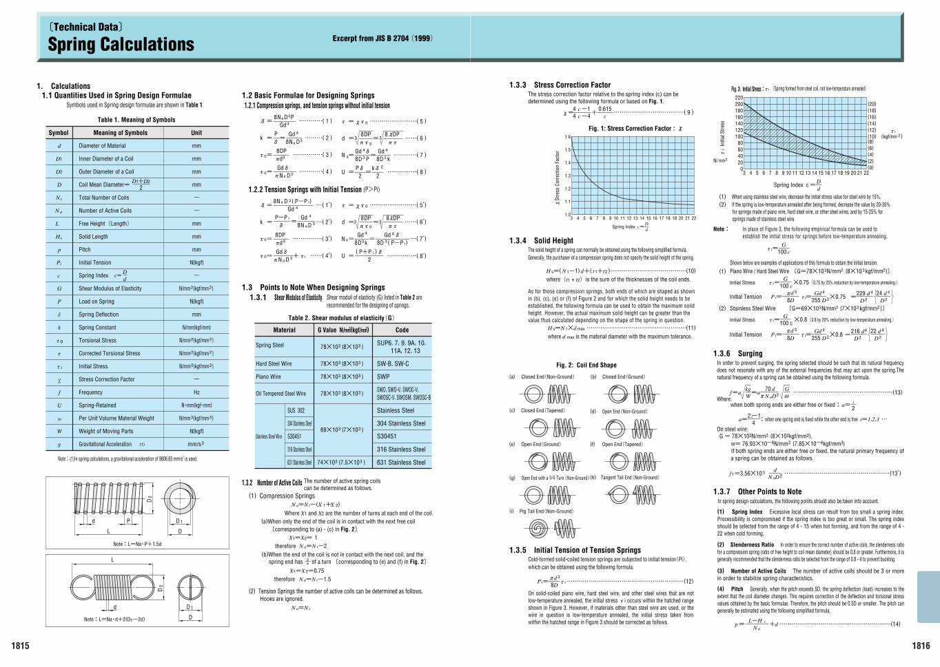
(2) If the spring is low-temperature annealed after being formed, decrease the value by 20-35% for springs made of piano wire, hard steel wire, or other steel wires, and by 15-25% for springs made of stainless steel wire.

(1) When using stainless steel wire, decrease the initial stress value for steel wire by 15%.

(Spring formed from steel coil, not low-temperature annealed)i

Open End with a Turn(Non-Ground)

E

1.3.7 Other Points to Note

G = 78M103N/mm2 {8M103kgf/mm2},

i=1,2,3i

a= :when one spring end is fixed while the other end is free42

when both spring ends are either free or fixed:

1.3.6 Surging

2323 }»kgf/mm{7M10N/mm’G=69M10Stainless Steel Wire

}»2kgf/mm3{8M102N/mm 3’G=78M10Piano Wire / Hard Steel WireShown below are examples of applications of this formula to obtain the initial tension.

In place of Figure 3, the following empirical formula can be used to establish the initial stress for springs before low-temperature annealing.

Note:

Fig. 3: Initial Stress:

Spring Index c

1.3.5 Initial Tension of Tension SpringsCold-formed solid-coiled tension springs are subjected to initial tension(Pi),

Fig. 2: Coil End Shape

Pig Tail End(Non-Ground)

Tangent Tail End(Non-Ground)

Open End(Non-Ground) Closed End(Tapered)

Open End(Tapered) Open End(Ground)

Closed End(Ground) Closed End(Non-Ground) (b)

where(t1 + t2)is the sum of the thicknesses of the coil ends.

As for those compression springs, both ends of which are shaped as shown in (b), (c), (e) or (f) of Figure 2 and for which the solid height needs to be established, the following formula can be used to obtain the maximum solid height. However, the actual maximum solid height can be greater than the value thus calculated depending on the shape of the spring in question.

where d max is the material diameter with the maximum tolerance.

The solid height of a spring can normally be obtained using the following simplified formula. 1.3.4 Solid Height

Fig. 1: Stress Correction Factor:◊

The stress correction factor relative to the spring index (c) can be determined using the following formula or based on Fig. 1.

1.3.3 Stress Correction Factor

100 cG

=i

=iPd 3

D8 i=255 D4Gd

2M0.8D

422 d22

d=

216 4

D

i

2a=

D

4229=

d2 2

d24 4

DM0.752

Gd 4

D255=i8D3d

Pi=

3/4

mm2N/

i In

itial

Stre

ss

◊St

ress

Cor

rect

ion

Fact

or

-1

τ

τ

τ

τ

τ

τ

π

π

On solid-coiled piano wire, hard steel wire, and other steel wires that are not low-temperature annealed, the initial stress Íi occurs within the hatched range shown in Figure 3. However, if materials other than steel wire are used, or the wire in question is low-temperature annealed, the initial stress taken from within the hatched range in Figure 3 should be corrected as follows.

w= 76.93M10-6N/mm3 {7.85M10-6kgf/mm3} If both spring ends are either free or fixed, the natural primary frequency of a spring can be obtained as follows.

In order to prevent surging, the spring selected should be such that its natural frequency does not resonate with any of the external frequencies that may act upon the spring.The natural frequency of a spring can be obtained using the following formula.

(1) Spring Index Excessive local stress can result from too small a spring index. Processibility is compromised if the spring index is too great or small. The spring index should be selected from the range of 4 - 15 when hot forming, and from the range of 4 - 22 when cold forming.

(4) Pitch Generally, when the pitch exceeds 5D, the spring deflection (load) increases to the extent that the coil diameter changes. This requires correction of the deflection and torsional stress values obtained by the basic formulae. Therefore, the pitch should be 0.5D or smaller. The pitch can generally be estimated using the following simplified formula.

(2) Slenderness Ratio In order to ensure the correct number of active coils, the slenderness ratio for a compression spring (ratio of free height to coil mean diameter) should be 0.8 or greater. Furthermore, it is generally recommended that the slenderness ratio be selected from the range of 0.8 - 4 to prevent buckling.

(3) Number of Active Coils The number of active coils should be 3 or more in order to stabilize spring characteristics.

Spring Index

Where:

On steel wire:

SWOSC-V, SWOSM, SWOSC-BSWO, SWO-V, SWOC-V,

11A, 12, 13SUP6, 7, 9, 9A, 10,

78M103 {8M103 }

}3{8M10378M10

316 Stainless Steel

631 Stainless Steel

304 Stainless Steel

S30451

Stainless Steel

SWP

SW-B, SW-C

SUS 302

304 Stainless Steel

316 Stainless Steel

631 Stainless Steel }3{7.5M10374M10

69M103 {7M103 }

78M103 {8M103 }

}3{8M10378M10

1D

DL

d P

2D

1

D

Dd

2D

L

i

i

t

a

s

g

W

U

f

k

P

G

c

P

p

H

L

N

N

D

D

D

d

2

NCmm{kgfCmm}

}2{kgf/mm2

mm/s

N{kgf}

-

Hz

N/mm{kgf/mm}

mm

N/mm

N{kgf}

N{kgf}

-

mm

mm

mm

-

-

mm

mm

mm

mm

S30451

}2{kgf/mm2N/mm

}2{kgf/mm2N/mm

}2{kgf/mm2N/mm

}3{kgf/mm3N/mm

1

2

1815

τ

τ

τ

E( 7V)

22

Î)iP+Pi)P-P

iÍ+ EE( 4V)

iE( 2V)

)iP-P= E( 1V)

8N a D 3(Gd

k =P-PÎ

=Gd

8N a D 3

4

Í8DPQ 3 EEEEE( 3V)=0

d

0=Í 2Q

GdÎN a D

=Í EEEEEEEE( 5V)◊Í0

EE( 6V)d =8DP

=QÍ0

3ÍQ

◊8 DP

N =a 8D 3 (Gd 4Î

=Gd

8

4

D3 k

EEEEE( 8V)U =2

(

2kÎ=

PÎ=U EEEEE( 8 )

k3D

4

8Gd

=Î4GdP3D8a EEEE( 7 )=N

DP8QÍ

330ÍQ=

DP8=d EE( 6 )

0Í◊ EEEEEEEE( 5 )Í =

DaNGdÎQ 2 EEEE( 4 )Í =0

d0= EEEEE( 3 )3Q

DP8Í

4

3DaN8Gd

P= EEE( 2 )k

4GdP3DaN8EEEE( 1 )Î

4

3

Î

=

(1)

c=dD

22D1D

Hooks are ignored.

’corresponding to (a) - (c) in Fig. 2»

Where X1 and X2 are the number of turns at each end of the coil.X

(a)When only the end of the coil is in contact with the next free coil

-1.5

Na= tN

N t=aN

Na= t-2N

X1=X 2=0.75therefore

(b)When the end of the coil is not in contact with the next coil, and the spring end has of a turn ’corresponding to (e) and (f) in Fig. 2»

therefore1X1=X2=

X(N )2+1-t=aN

(2) Tension Springs the number of active coils can be determined as follows.

(1) Compression Springs

The number of active spring coils can be determined as follows.

1.3.2 Number of Active Coils

Stainless Steel Wire

Piano Wire

Oil Tempered Steel Wire

Hard Steel Wire

Spring Steel

CodeG Value N/E(kgf/E)Material

Table 2. Shear modulus of elasticity(G)

Shear moduli of elasticity (G) listed in Table 2 are recommended for the designing of springs.

1.3 Points to Note When Designing Springs 1.3.1 Shear Modulus of Elasticity

1.2.2 Tension Springs with Initial Tension (P>Pi)

1.2.1 Compression springs, and tension springs without initial tension1.2 Basic Formulae for Designing Springs

Note:L=NaCP+1.5d

Note:L=NaCd+2(D2-2d)

Note:(1)In spring calculations, a gravitational acceleration of 9806.65 mm/s2 is used.

Spring-Retained

Gravitational Acceleration

Weight of Moving Parts

Per Unit Volume Material Weight

Frequency

Stress Correction Factor

Initial Stress

Corrected Torsional Stress

Torsional Stress

Spring Constant

Spring Deflection

Load on Spring

Shear Modulus of Elasticity

Spring Index

Initial Tension

Pitch

Solid Length

Free Height(Length)

Number of Active Coils

Total Number of Coils

Coil Mean Diameter=

Outer Diameter of a Coil

Inner Diameter of a Coil

Diameter of Material

Symbol UnitMeaning of Symbols

Symbols used in Spring design formulae are shown in Table 1.

Table 1. Meaning of Symbols

1.1 Quantities Used in Spring Design Formulae1. Calculations

43

Excerpt from JIS B 2704(1999)Spring Calculations’Technical Data»

+

Metric_1801-1886 3/1/06 10:29 Page 1814