spread spectrum analysis for cdma system - welcome to ethesis
TRANSCRIPT
SPREAD SPECTRUM ANALYSIS FOR CDMA SYSTEM
A THESIS SUBMITTED IN PARTIAL FULFILLMENT OF THE
REQUIREMENTS FOR THE DEGREE OF
Bachelor of Technology in Electronics & Communication Engineering
BY
MANGAT PRASAD SOREN
ROLL NO: 10609018
DEPARTMENT OF ELECTRONICS & COMMUNICATION ENGINEERING NATIONAL INSTITUTE OF TECHNOLOGY
ROURKELA-769008
2010

SPREAD SPECTRUM ANALYSIS FOR CDMA SYSTEM
A THESIS SUBMITTED IN PARTIAL FULFILLMENT OF THE
REQUIREMENTS FOR THE DEGREE OF
Bachelor of Technology in Electronics & Communication Engineering
BY
MANGAT PRASAD SOREN
ROLL NO: 10609018
Under the guidance of
Associate Prof. (Mrs.) Poonam Singh
DEPARTMENT OF ELECTRONICS & COMMUNICATION ENGINEERING NATIONAL INSTITUTE OF TECHNOLOGY
ROURKELA-769008
2010
CERTIFICATE
This is to certify that the thesis entitled ―Spread Spectrum Analysis For CDMA
system‖ submitted by Mangat Prasad Soren (Roll No. 10609018) in partial
fulfillment of the requirements for the award of Bachelor of Technology in the
department of Electronics & Communication Engineering, National Institute of
Technology, Rourkela is an authentic work carried out under my supervision and
guidance.
To the best of my knowledge, the matter embodied in the thesis has not been
submitted to elsewhere for the award of any degree.
Place: Rourkela Associate Prof. (Mrs.) Poonam Singh
Date: Electronics & Communication Engineering
Department
National Institute of Technology
Rourkela-769008

ACKNOWLEDGEMENT
It gives me immense pleasure to express my deep sense of gratitude to my supervisor
Associate Prof. (Mrs.) Poonam Singh for her invaluable guidance, motivation,
constant inspiration and above all her ever co-operating attitude enabled me in
bringing up this thesis in present elegant form.
I am extremely thankful to Prof. S. K. Patra, Head, Department of Electronics &
Communication Engineering and the faculty members of Electronics &
Communication Engineering Department for providing all kinds of possible help and
advice during the course of this work.
It is a great pleasure for me to acknowledge and express my gratitude to my parent for
their understanding, unstinted support and endless encouragement during my study.
I am greatly thankful to all the staff members of the department and all my well
wishers, class mates and friends for their inspiration and help.
Lastly I sincerely thank to all those who have directly or indirectly helped for the
work reported herein.
MANGAT PRASAD SOREN
ROLL NO: 10609018
Department of Electronics & Communication Engineering
National Institute of Technology, Rourkela
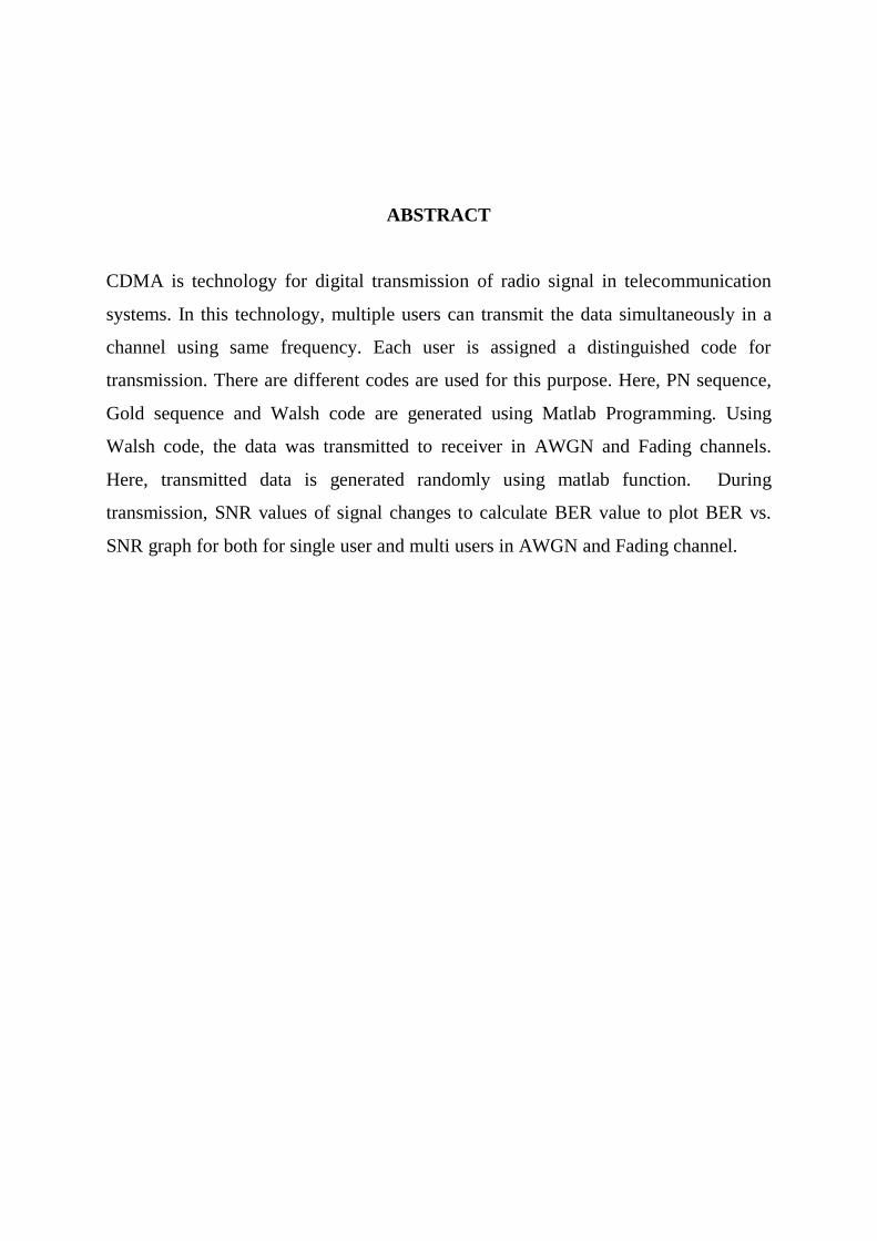
ABSTRACT
CDMA is technology for digital transmission of radio signal in telecommunication
systems. In this technology, multiple users can transmit the data simultaneously in a
channel using same frequency. Each user is assigned a distinguished code for
transmission. There are different codes are used for this purpose. Here, PN sequence,
Gold sequence and Walsh code are generated using Matlab Programming. Using
Walsh code, the data was transmitted to receiver in AWGN and Fading channels.
Here, transmitted data is generated randomly using matlab function. During
transmission, SNR values of signal changes to calculate BER value to plot BER vs.
SNR graph for both for single user and multi users in AWGN and Fading channel.

CONTENTS
Chapter No. Description Page No.
Chapter 1 1. INTRODUCTION
1.1. Spread Spectrum
1.2. Direct Sequence Spread Spectrum
1.3. Direct Sequence CDMA
1.4. Code Division Multiple Access
1.5. Fading
2-10
Chapter 2 2. PROPOSED WORK
2.1 Proposed Work
12-12
Chapter 3 3. WORK DONE
3.1. Generation of Codes
3.1.1. PN sequence Generation
3.1.2. Gold sequence Generation
3.1.3. Walsh code Generation
3.2. Single user CDMA in AWGN channel
3.3. Multi -user CDMA in AWGN channel
3.4.Multi-Users CDMA in AWGN and Fading
Channel
14-17
Chapter 4 4.RESULTS
4.1. Introduction
4.2. BER vs. SNR graph for single user CDMA in
AWGN channel
4.3.BER vs. SNR graph for Multi-user CDMA in
AWGN channel
4.4. BER vs. SNR graph for Multi-user CDMA in
AWGN and Fading channel
19-21
Chapter 5 5. CONCLUSIONS
5.1. Scope for Future Work
23-23
REFERENCES 25-26
Lists of figures
Figure:1.1. Model of basic spread spectrum technique
Figure:1.2. Transmitter and receiver model of CDMA system
Figure: 3.1. PN sequence generator
Figure:3.2. Output of PN sequence generation using matlab
Figure:3.3. Gold sequence generator
Figure:3.4. Output of gold sequence generation using matlab
Figure:3.5. Output of Walsh code generation using matlab
Figure.4.1. BER vs. SNR graph for single user CDMA in AWGN channel
Figure.4.2. BER vs. SNR graph for Multi-user CDMA in AWGN channel
Figure.4.3. BER vs. SNR graph for Multi-user CDMA in AWGN and Fading channel

1
Chapter 1
INTRODUCTION
2
CHAPTER 1
1. INTRODUCTION
Code Division Multiple Access (CDMA) is used as a multiple access technique in
telecommunications radio system that can transport multimedia traffic at high data
rates. The communications researchers have studied CDMA and are further
developing it. This has come out because of the various reasons which contributed to
evolution in wireless technology.
They include:
Need for highly reliable telecom network and most important and security
against eavesdropping and cryptanalysts.
Implementation of inexpensive data network.
End users need new services, like new telephony and internet services.
Explosive growth of data leading to market growth.
Introduction of new services imposed by technology changes.
MC CDMA networks proposed for fourth generation (4G) system, that will be
defined by the ability to integrate heterogeneous networks, especially radio mobile
networks and wireless networks, that offers access to all services, all the time and
everywhere . Above and beyond, the rapid growth of internet services and the
increasing interest in portable computing devices are probable to create a strong
demand for high speed wireless data services. Key issues to fully meet these evolution
perspectives are based upon the multi-carrier systems which have become popular for
their spectral efficiency and robustness against frequency-selective fading. Multi-
carrier code division multiple access (MC CDMA) is a technique that combines the
advantage of multi-carrier modulation with that of code division multiple access to
offer reliable high data rate downlink cellular communication services. It is used as it
has proven to be better than conventional CDMA networks, FDMA and TDMA. The
eventual real effects and alternative conditions and courses of action of the network
need to be thoroughly exploited before the deployment.
3
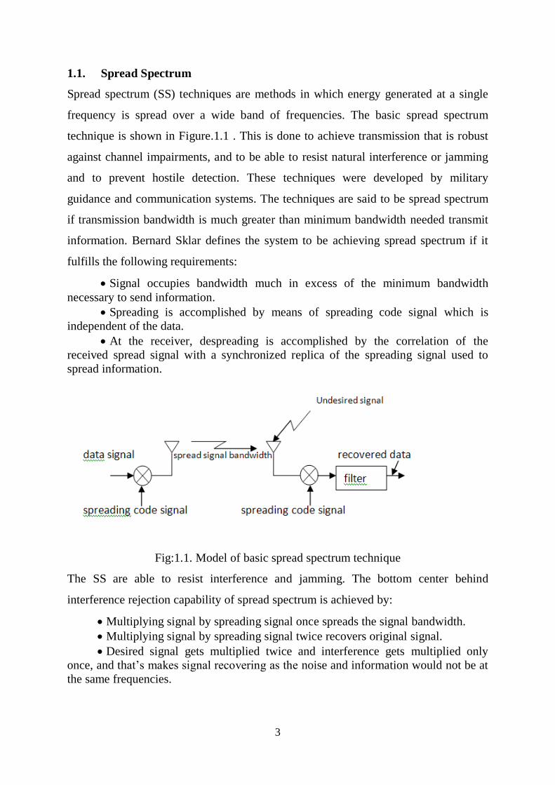
1.1. Spread Spectrum
Spread spectrum (SS) techniques are methods in which energy generated at a single
frequency is spread over a wide band of frequencies. The basic spread spectrum
technique is shown in Figure.1.1 . This is done to achieve transmission that is robust
against channel impairments, and to be able to resist natural interference or jamming
and to prevent hostile detection. These techniques were developed by military
guidance and communication systems. The techniques are said to be spread spectrum
if transmission bandwidth is much greater than minimum bandwidth needed transmit
information. Bernard Sklar defines the system to be achieving spread spectrum if it
fulfills the following requirements:
Signal occupies bandwidth much in excess of the minimum bandwidth
necessary to send information.
Spreading is accomplished by means of spreading code signal which is
independent of the data.
At the receiver, despreading is accomplished by the correlation of the
received spread signal with a synchronized replica of the spreading signal used to
spread information.
Fig:1.1. Model of basic spread spectrum technique
The SS are able to resist interference and jamming. The bottom center behind
interference rejection capability of spread spectrum is achieved by:
Multiplying signal by spreading signal once spreads the signal bandwidth.
Multiplying signal by spreading signal twice recovers original signal.
Desired signal gets multiplied twice and interference gets multiplied only
once, and that’s makes signal recovering as the noise and information would not be at
the same frequencies.
4
Conventional modulation schemes such as frequency modulation and pulse code
modulation also spread the spectrum of an information signal, but they do not qualify
as spread spectrum systems since they do not satisfy all the conditions as outlined.
Spread spectrum techniques are implemented where transmission has to be operated
without information being detected by anyone other than the intended receiver.
Communications systems designed for this task are known as low probability of
detection ( LPD ) or low probability of intercept filter (LPI). SS systems that are
designed to present LPI may also be designed to expose low probability of position fix
(LPPF), thus even if the presence of the signal may be perceived, direction of the
transmitter is difficult to pinpoint. They can further be made to expose low probability
of signal exploitation (LPSE), meaning that identification of source is difficult to
determine. The goal of these systems is to use minimum signal power and optimum
signaling scheme that results in minimum probability of being detected, intercepted or
demodulated. SS uses wide band, noise-like signals and because the signals are noise-
like, they are hard to detect. Further, Spread Spectrum signals are harder to jam than
narrowband signals. Spread spectrum techniques use code signal to perform spreading
and despreading, and these spreading code signals are called pseudorandom or
pseudonoise codes. They are called pseudorandom because they are not random at all;
they are deterministic periodic signals that are known to both transmitter and receiver.
Though these signals are said to be deterministic, they hold randomness properties and
they appear random to unauthorized users. Spread spectrum techniques can be
classified into three main categories namely direct sequence spread spectrum,
frequency hopping spread spectrum and time hopping spread spectrum and the
combination of two of the three techniques.
1.2. Direct Sequence Spread Spectrum
A direct sequence spread spectrum signal is one in which the amplitude of an already
modulated signal is amplitude modulated by a high rate NRZ binary stream of digits.
Thus, if the original signal is s(t), where
s(t)= sqrt(2*Ps)d(t)cos w₀t
(a binary PSK signal), the DS spread spectrum signal is
v(t)= g(t)s(t)

5
where g(t) is a pseudo-random noise (PN) binary sequence having the values +1 or -1.
A direct sequence system uses a locally generated pseudo noise code to encode digital
data to be transmitted. The local code runs at much higher rate than the data rate. The
data is logically modulo-2 added with pseudo noise code signal. If the data signal is
narrowband compared to the spreading signal, the resulting product signal will have
the bandwidth approximated to that one of the spreading signal.
At the receiver direct sequence uses a locally generated replica pseudo noise code and
a receiver correlator to separate the desired coded information from all possible
signals. The correlator responds only to signals that are encoded with a pseudo noise
code that matches its own code.
1.3. Direct Sequence CDMA
Direct sequence (DS) CDMA is used in the third-generation mobile communication
standard to provide high capacity and high transmission rate over conventional
schemes such as frequency division multiple access and time-division multiple access.
However, due to inherent wide bandwidth of the spread spectrum systems, severe
frequency selective fading degrades system performances. When transmitting data in
the downlink, DS CDMA relies on the orthogonality of the spreading codes to
separate the different user signals.
However, it suffers from inter channel interference (ICI) and it destroys the
orthogonality among users, giving rise to Multi User Interference (MUI). Since the
multi user interference is in actual fact caused by the multipath channel, it can be
suppress by linear chip level equalization, followed by correlation with the user’s
spreading code.

6
Transmitter Model:
Receiver Model:
Fig:1.2. Transmitter and receiver model of CDMA system
At the transmitter, the information is encoded using codes. The encoded information is
then transformed into a data modulated symbol sequence with a baseband modulator.
The modulated symbol sequence is spread in time domain by a chip sequence of
orthogonal code generator, usually Walsh code and PN sequence. The information is
shaped and passed through a channel for transmission. At the receiver, the information
is multiplied with the chip sequence by the correlators in the rake receiver. The
information is then summed and multiplied by local generated spreading code, which
is despreading. The information is demodulated and decoded and original data can be
recovered.
1.4. Code Division Multiple Access
Code Division Multiple Access is a technology for digital transmission of radio
signals in telecommunications systems. It can be both synchronous and asynchronous.
In CDMA, each user is assigned a distinguished code and multiple users can transmit
data simultaneously using same frequency. They are distinguished by theirs codes.
7
The idea of CDMA was originally developed for military use developed by Allies in
World War II.
In a traditional hard handoff, the connection to the current cell is broken and then the
connection to the new cell is made. Since CDMA uses the same frequency, the
connection to the new cell site can be made without breaking the connection of the
current cell which is known as soft handoff. Soft handoff requires less power, which
reduces interference and increases capacity. The network chooses one or more
alternative sites that it feels are handoff candidates while a call is in progress. It
simultaneously broadcasts a copy of the call in each of these sites. It can then choose
one of the sites and can move between them whenever it feels like it. This puts the
phone in complete control of the handoff process.
These are the following features of the CDMA technology:-
The technology allows multiple calls to be carried over one channel.
It is used as a multiplexing platform and offers the opportunities to be improved.
It is considered efficient and secure technology as it provides communications
privacy since transmission cannot be interpreted by unauthorized users without code.
Operates at lower power level.
The technology is more robust to fading channels.
Spread spectrum techniques used affords the jamming resistance.
Advantages of CDMA:
One of the main advantages of CDMA is that dropouts occur only when the phone is
at least twice as far from the base station. Thus it is used in the rural areas where GSM
cannot cover. Another advantage is its capacity; it has a very high spectral capacity
that it can accommodate more users per MHz of bandwidth. It uses a EVRC for noise
reduction where the background noise is reduced. This is exclusively available in
CDMA technology only.
8
Disadvantages of CDMA:
One major problem in CDMA technology is channel pollution, where signals from too
many cell sites are present in the subscriber’s phone but none of them is dominant.
When this situation arises the quality of the audio degrades. Another disadvantage in
this technology when compared to GSM is the lack of international roaming
capabilities. The ability to upgrade or change to another handset is not easy with this
technology because the network service information for the phone is put in the actual
phone unlike GSM which uses SIM card for this. One another disadvantage is the
limited variety of the handset, because at present the major mobile companies use
GSM technology.
1.5. Fading
Small-scale fading or fading is used to describe the rapid fluctuations of the
amplitudes, phases or multipath delays of a radio signal over a short period of time or
travel distance, so that large-scale path loss effects may be ignored. Fading is caused
by interference between two or more versions of the transmitted signal which arrive at
the receiver at slightly different times. These waves, called multipath waves, combine
at the receiver antenna to give a resultant signal which can vary widely in amplitude
and phase, depending on the distribution of the intensity and relative propagation time
of the waves and the bandwidth of the transmitted signal.
Multipath in the radio channel creates small-scale fading effects. The three most
important effects are:
Rapid changes in signal strength over a small travel distance or time interval.
Rapid frequency modulation due to varying Doppler shifts on different
multipath signals.
Time dispersion (echoes) caused by multipath propagation delays.
9
Factors Influencing Small-Scale Fading
Multipath propagation--The presence of reflecting objects and scatterers in the
channel creates a constantly changing environment that dissipates the signal
energy in amplitude, phase, and time. These effects result in multiple versions
of the transmitted signal that arrive at the receiving antenna, displaced with
respect to one another in time and spatial orientation. The random phase and
amplitudes of the different multipath components cause fluctuations in signal
strength, and causes small-scale fading and signal distortion.
Speed of the mobile--The relative motion between the base station and the
mobile results in random frequency modulation due to different Doppler shifts
on each of the multipath components.
Speed of surrounding objects--If objects in the radio channels are in motion,
they induce a time varying Doppler shift on multipath components. If the
surrounding objects move at a greater rate than a mobile, then this effect
dominates the small-scale fading.
The transmission bandwidth of the signal—If the transmitted radio signal
bandwidth is greater than the bandwidth of the multipath channel, the received
signal will be distorted, but the received signal strength will not fade much over
a local area.
Rayleigh fading Distribution
In mobile radio channels, the Rayleigh distribution is commonly used to describe the
statistical time varying nature of the received envelope of a flat fading signal, or the
envelope of an individual multipath component. It is well known that the envelope of
the sum of two quadrature Gaussian noise signals obeys a Rayleigh distribution.
10
The Rayleigh distribution has a probability density function (pdf) given by
p(r)=r/a² *exp(-r²/(2*a²))
Where a is the rms value of the received voltage signal before envelope detection and
a² is the time-average power of the received signal before envelope detection.

11
Chapter 2
PROPOSED WORK

12
CHAPTER 2
2. PROPOSED WORK
The objective of project is to study and analysis the spread spectrum application for
CDMA systems. This includes
Generation of various codes like PN codes, Gold codes, Walsh codes.
Using these codes, a CDMA system is to be designed.
Analysis of spread spectrum by using Walsh code.
To design CDMA systems for both single and multi users.
Introduced coded transmitted signal through AWGN channel.
Plot BER vs. SNR graphs for both AWGN and fading channel.

13
Chapter 3
WORK DONE

14
CHAPTER 3
3.1. Generation of Codes
3.1.1. PN Sequence Generation
A piece of hardware which is widely used to generate PN sequences in shown in
figure.3.1. It consists initially of a shift register. We have selected D-type flip-flops
and arranged that each data input except D₀ is the Q output of the preceding filp-flop.
The input D₀ is the output of the parity generator. A parity generator is generally
constructed of an array of exclusive-or logic gates. The character of the PN sequence
generated depends on the number N of flip-flops employed and on the selection of
which flip-flop outputs are connected to the parity generator.
Figure: 3.1. PN sequence generator
Figure:3.2. Output of PN sequence generation using matlab
15
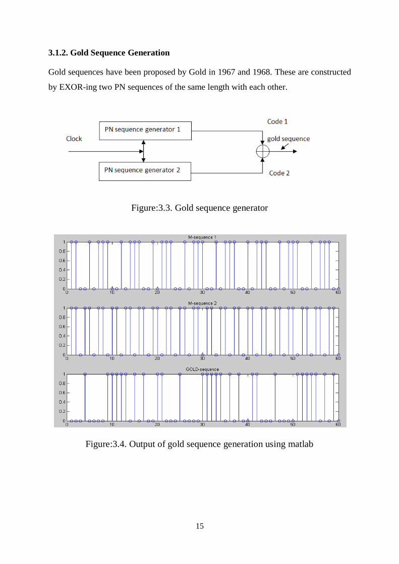
3.1.2. Gold Sequence Generation
Gold sequences have been proposed by Gold in 1967 and 1968. These are constructed
by EXOR-ing two PN sequences of the same length with each other.
Figure:3.3. Gold sequence generator
Figure:3.4. Output of gold sequence generation using matlab
16
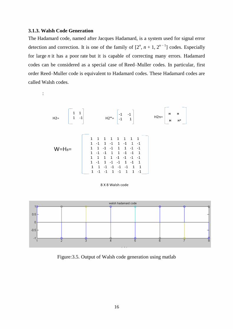
3.1.3. Walsh Code Generation
The Hadamard code, named after Jacques Hadamard, is a system used for signal error
detection and correction. It is one of the family of [2n, n + 1, 2
n − 1] codes. Especially
for large n it has a poor rate but it is capable of correcting many errors. Hadamard
codes can be considered as a special case of Reed–Muller codes. In particular, first
order Reed–Muller code is equivalent to Hadamard codes. These Hadamard codes are
called Walsh codes.
:
Figure:3.5. Output of Walsh code generation using matlab

17
3.2. Single User CDMA in AWGN Channel
Using 8 bits Walsh code, the single data which will be transmitting through channel to
receiver is multiply with same Walsh code. This is called spreading. This coded data
will be transmitted through AWGN channel. At receiver end, the local generated
Walsh code will multiply with received signal for dispreading. For receiving data at
receiver end rake receiver is used. The despread data will pass through filter to get
back desired data.
3.3. Multi-Users CDMA in AWGN Channel
Here instead of taking single Walsh code, eight Walsh codes will take foe sending
eight different data from different users. The whole process is same as process of
sending single data in AWGN channel in CDMA. The number of Walsh code required
is depend upon how much data bits will send at transmitter end. The Walsh code can
be generated using Hadamard matrix. Since these Walsh codes are orthogonal to each
other, inter signal interference is very low.
3.3. Multi-Users CDMA in AWGN and Fading Channel
Here encodes (spread) signals will transmit through both AWGN channel and Fading
channel. Fading is caused by interference between two or more versions of the
transmitted signal which arrive at the receiver at slightly different times. Here fading
channel is Rayleigh fading channel. The method of regenerating data signal from
received signal is multiplying Walsh code and despread the received signal which will
pass through filter to recover desired data.

18
Chapter 4
RESULTS

19
CHAPTER 4
4.1. Introduction
Bit error rate (BER) of a communication system is defined as the ratio of number of
error bits and total number of bits transmitted during a specific period. It is the
likelihood that a single error bit will occur within received bits, independent of rate of
transmission. There are many ways of reducing BER. Here, we focus on spreading
code & modulation techniques.
In our case, we have considered the most commonly used channel: the Additive White
Gaussian Noise (AWGN) channel where the noise gets spread over the whole
spectrum of frequencies.
BER has been measured by comparing the transmitted signal with the received signal
and computing the error count over the total number of bits. For any given
modulation, the BER is normally expressed in terms of signal to noise ratio (SNR).
4.2. BER vs. SNR graph for single user CDMA in AWGN channel
fig:4.1. BER vs. SNR garph
20
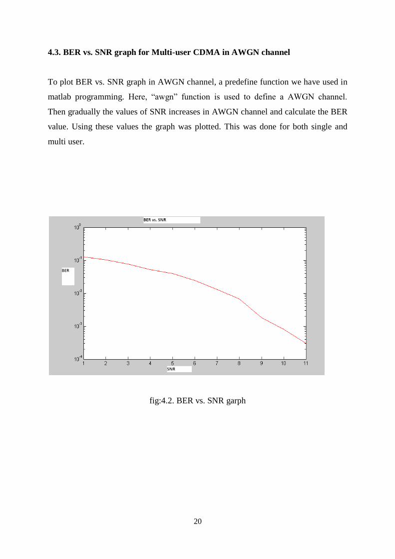
4.3. BER vs. SNR graph for Multi-user CDMA in AWGN channel
To plot BER vs. SNR graph in AWGN channel, a predefine function we have used in
matlab programming. Here, ―awgn‖ function is used to define a AWGN channel.
Then gradually the values of SNR increases in AWGN channel and calculate the BER
value. Using these values the graph was plotted. This was done for both single and
multi user.
fig:4.2. BER vs. SNR garph

21
4.4. BER vs. SNR graph for Multi-user CDMA in AWGN and Fading
channel
To plot BER vs. SNR graph in AWGN and Fading channel, predefine functions
we have used in matlab programming. Rayleigh fading channel is used as fading
channel. Here, ―awgn‖ and ―rayleighchan‖ functions are used to define a AWGN
channel and a fading channel simultaneously. Then gradually the values of SNR
increases and calculate the BER value. Using these values the graph was plotted.
This was done for both single and multi user
fig:4.3. BER vs. SNR garph
22
Chapter 5
CONCLUSIONS

23
CHAPTER 5
5. CONCLUSIONS
This work shows that successfully completion of analysis of spread spectrum
for CDMA systems.
The generation of PN codes, Walsh codes and gold codes was successfully
obtained by using matlab programming.
BER vs. SNR graphs for single user and multi users in both AWGN and Fading
channel plotted and analysed successfully using matlab programming. Matlab
provides a simple, systematic and efficient methodology for solving
communication and data signal processing problems. This is one of the
approaches to solve and design communication model before fabricating a
system.
The results indicate that after certain value of SNR, BER value will be zero in
each channel.
5.1. Scope for Future Work
This study leaves wide scope for future investigations. It can be extended to
analysis of interference in CDMA due to fading channel and how to cancel that
interference.
CDMA technology is more useful for 3G and 4G mobile generations. There is
a very wide scope for future scholars to explore this area of research in the field
of CDMA. Many other problems like capacity, high data speed rate and low
interference are require further investigation.
******

24
REFERENCES

25
REFERENCES
REFERENCES
1. T.S.Rappaport. Wireless Communications –principles and practices,
2nd
Edition, (2002 by Prentice-Hall), Upper Saddle River, New Jersey.
Ch.5.
2. H. Taub, D. L. Schilling and G. saha, ―Principles of communication systems‖,
third edition,(2008 by Tata McGraw-Hill), ch.15.
3. `Mabula Martina Cheeli, ―CDMA network simulator for wireless
communication applications‖, Graduation Degree Thesis, Department of
Electrical Engineering, University of Cape Town 2006.
4. Bernard Sklar, ―Rayleigh Fading Channels in Mobile Digital Communication
Systems Part I: Characterization‖, IEEE Communications Magazine ,July 1997.
5. Tsokolo Masike, MSWTSO001, ―Development of a DS-CDMA Network
Simulator for wireless cellular network Applications‖, Graduation Degree
Thesis, Department of Electrical Engineering, University of Cape Town 2006.
6. J. Proakis; ―Digital Communications‖, McGraw-Hill, 4th
Edition, 2001.
7. Carl Andren,, Harris Semiconductor ,Palm Bay, Florida, ―Short PN Sequences
for Direct Sequence Spread Spectrum Radios‖.
8. L.Nithyanandan , P.Dananjayan, ―Analytical BER Computation For
Interference Cancellation Receiver In Mc-CDMA System.‖, Dept. of
Electronics and Communication Engineering, Pondicherry Engineering
College, Pondicherry-605014, India.
9. B. P. Lathi, ―Modern Digital and Analog communication Systems‖, third
edition, New York oxford, Oxford University Press, 1998.
10. Simon Haykin, ― Communication Systems‖, 4th
edition, 2001, John Willey &
Sons, Inc.
26
11. ―Code Division Multiple Access (CDMA), The Concept of signal spreading
and its uses in communications‖, 2006 Charan Langton, at
www.complextoreal.com.
12. ir.j. Meel, ―Spread Spectrum (SS)‖, DA NAYER INSTITUUT, Belgium.
13. ―CDMA vs. TDMA‖, Sabareeshwar Natarajan., Fall 2006, DTEC 6810,
Communication Technology.
54644646