sportdyno v3.8 user’s manual -...
TRANSCRIPT

SportDevices.com SportDyno 3.8 Page 1/55
Printed: 1/December/2015
SPORTDYNO V3.8
USER’S MANUAL
Copyright © 2015

SportDevices.com SportDyno 3.8 Page 2/55
Printed: 1/December/2015
TABLE OF CONTENTS 1. MAIN SCREEN. ..................................................................................................................... 5
1.1 Main Menu ........................................................................................................................ 5
1.2 File Menu .......................................................................................................................... 5
1.2.1 Remove All. ............................................................................................................. 5
1.2.2 Open. ....................................................................................................................... 6
1.2.3 Change directory. .................................................................................................... 6
1.2.4 Save as. ................................................................................................................... 6
1.2.5 Save picture. ............................................................................................................ 6
1.2.6 Export speed data.................................................................................................... 6
1.2.7 Export HP data. ....................................................................................................... 6
1.2.8 Preview. ................................................................................................................... 6
1.2.9 Print. ........................................................................................................................ 6
1.2.10 Exit. .......................................................................................................................... 6
1.3 Test Menu......................................................................................................................... 7
1.3.1 Run (F5). .................................................................................................................. 7
1.3.2 Test ratio (F7). ......................................................................................................... 7
1.3.3 Hide Negative Part................................................................................................... 7
1.3.4 Calculate Power Curve with Losses. ....................................................................... 7
1.3.5 Histogram. ............................................................................................................... 7
1.3.6 Make average. ......................................................................................................... 7
1.3.7 Calculate Slip % ....................................................................................................... 8
1.3.8 Filter RPM Channel. ................................................................................................ 8
1.3.9 Filter Analog Channel. ............................................................................................. 8
1.3.10 Generate RPM Channel. ......................................................................................... 8
1.3.11 Add / Modify Channel. ............................................................................................. 8
1.3.12 Remove Channel. .................................................................................................... 9
1.3.13 Remove Test. .......................................................................................................... 9
1.3.14 Delete Test. ............................................................................................................. 9
1.3.15 Properties. ............................................................................................................... 9
1.4 Options Menu ................................................................................................................... 9
1.4.1 Configuration. .......................................................................................................... 9
1.4.2 Throttle Configuration [NEW] ................................................................................... 9
1.4.3 Relays Control [NEW] ............................................................................................ 10
1.4.4 PID Configuration. ................................................................................................. 10
1.4.5 PID Monitor [modified] ........................................................................................... 10
1.4.6 Sequencer. ............................................................................................................ 10
1.4.7 Load Cell Wizard. .................................................................................................. 10
1.4.8 Add Static Brake Losses. ...................................................................................... 10
1.5 Connections.................................................................................................................... 11
1.5.1 Auto Detect. ........................................................................................................... 11
1.5.2 COM1 - COM(n). ................................................................................................... 11
1.5.3 Reconnect [NEW] .................................................................................................. 11
1.5.4 USB Weather Station [NEW] ................................................................................. 11
1.5.5 OBDII [NEW] .......................................................................................................... 12
1.6 Channels Menu. ............................................................................................................. 13
1.6.1 Channel Settings. .................................................................................................. 13
1.6.2 Activation / Raw data. ............................................................................................ 13
1.6.3 Alarms. ................................................................................................................... 13
1.7 Help Menu ...................................................................................................................... 13
1.7.1 About. .................................................................................................................... 13
1.8 Button Bar....................................................................................................................... 13
1.9 Channel selector. ........................................................................................................... 15
1.10 Options for X Axis. ..................................................................................................... 16
1.11 Dyno run List .............................................................................................................. 16
1.12 Graphs Area ............................................................................................................... 19
1.13 Scroll Bars .................................................................................................................. 20
1.14 Status Bar .................................................................................................................. 20
2. GAUGES WINDOW ............................................................................................................. 21
2.1 Gauges’ area. ................................................................................................................. 21

SportDevices.com SportDyno 3.8 Page 3/55
Printed: 1/December/2015
2.2 Test data area ................................................................................................................ 22
2.2.1 Test Data .............................................................................................................. 22
2.2.2 Engine RPM ........................................................................................................... 23
2.2.3 Weather Data ......................................................................................................... 23
2.2.4 Test Mode .............................................................................................................. 24
2.2.5 Common area ........................................................................................................ 26
3. HOW TO DO A DYNO RUN? .............................................................................................. 27
3.1 WAY 1 (F5 KEY) ............................................................................................................ 27
3.2 WAY 2 (START/STOP BUTTON) .................................................................................. 27
4. RATIO WINDOW ................................................................................................................. 28
5. CONFIGURATION ............................................................................................................... 29
5.1 Dynamometer ................................................................................................................. 29
5.1.1 Dynamometer name .............................................................................................. 29
5.1.2 Roller Characteristics............................................................................................. 29
5.1.3 Class of Dyno ........................................................................................................ 29
5.1.4 SPx Device. ........................................................................................................... 30
5.1.5 Torque Calculation................................................................................................. 30
5.1.6 SPx configuration ................................................................................................... 30
5.1.7 SP4 / SP5 Specific ................................................................................................. 30
5.1.8 Lower Buttons ........................................................................................................ 30
5.2 Program Options. ........................................................................................................... 31
5.2.1 Tests ...................................................................................................................... 31
5.2.2 Language ............................................................................................................... 31
5.2.3 Printer Options ....................................................................................................... 32
5.2.4 Data table .............................................................................................................. 32
5.2.5 Units ....................................................................................................................... 33
5.3 Options Tab .................................................................................................................... 33
5.3.1 Options/Messages ................................................................................................. 33
5.3.2 Special Keys .......................................................................................................... 34
5.3.3 Filtering .................................................................................................................. 34
5.3.4 Corrections ............................................................................................................ 35
5.4 Colours ........................................................................................................................... 35
5.5 Constants ....................................................................................................................... 36
5.6 Advanced Options .......................................................................................................... 37
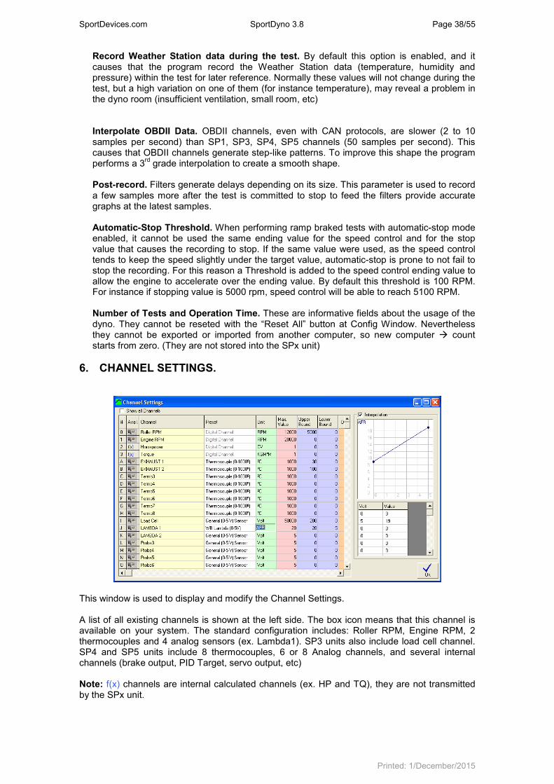
6. CHANNEL SETTINGS. ........................................................................................................ 38
6.1.1 Preset / Channel Type ........................................................................................... 39
6.1.2 Channel key ........................................................................................................... 39
6.1.3 Channel Name ....................................................................................................... 39
6.1.4 Unit......................................................................................................................... 39
6.1.5 Maximum value ...................................................................................................... 39
6.1.6 Upper bound, Lower bound ................................................................................... 39
6.1.7 Decimals ................................................................................................................ 39
6.1.8 (input ) Scale .......................................................................................................... 39
6.1.9 Graph Filter ............................................................................................................ 39
6.1.10 Group ..................................................................................................................... 40
6.1.11 Time Offset ............................................................................................................ 40
6.1.12 Interpolation ........................................................................................................... 40
6.1.13 Default Calculated Channels ................................................................................. 40
7. HISTOGRAM ....................................................................................................................... 40
8. LOAD CELL WIZARD .......................................................................................................... 42
8.1 Load Cell zeroing ........................................................................................................... 42
8.2 Load Cell Scale .............................................................................................................. 42
9. PID Monitor (SP4 / SP5) ...................................................................................................... 43
9.1 PID Mode........................................................................................................................ 43
9.1.1 Idle ......................................................................................................................... 43
9.1.2 Steady .................................................................................................................... 43
9.1.3 Ramp (Sweep Test) ............................................................................................... 43
9.1.4 Brake ..................................................................................................................... 43
9.2 Ramp Limits (Sweep) ..................................................................................................... 43
9.3 PID Settings.................................................................................................................... 43
9.4 Misc settings ................................................................................................................... 44
9.5 Recall Button .................................................................................................................. 44

SportDevices.com SportDyno 3.8 Page 4/55
Printed: 1/December/2015
9.6 Numeric Boxes ............................................................................................................... 44
10. SP4 / SP5 Specific Settings ................................................................................................. 44
10.1 PID Settings ............................................................................................................... 44
10.2 Ramp Limits (Sweep) ................................................................................................. 44
10.3 Air Speed ................................................................................................................... 44
10.4 Misc Settings .............................................................................................................. 45
10.4.1 Min Roller (SP5). ................................................................................................... 45
10.4.2 Max Roller (SP5). .................................................................................................. 45
10.4.3 Ratio. ..................................................................................................................... 45
10.4.4 Number of Teeth (geartooth). ................................................................................ 45
10.4.5 Prescaler (SP1 to SP4). ....................................................................................... 45
10.4.6 AWD Mode (SP5). ................................................................................................. 46
10.5 Brake Configuration ................................................................................................... 46
10.5.1 Brake for Emergency Stop (SP5). ......................................................................... 46
10.5.2 Brake offset. ........................................................................................................... 46
11. Throttle Configuration ........................................................................................................... 46
11.1 Throttle Setup ............................................................................................................. 46
11.2 Throttle Open / Close rate .......................................................................................... 46
11.3 Self-Tune .................................................................................................................... 46
12. SEQUENCER (SP4 / SP5) .................................................................................................. 47
12.1 “Standard” Sequence ................................................................................................. 47
12.2 File Sequence ............................................................................................................ 48
Sequencer Commands [updated] ............................................................................................ 48
12.3 CSV Simulation File ................................................................................................... 49
13. Calculated Channels ............................................................................................................ 50
13.1 How to use it? ............................................................................................................ 50
13.2 How to use the formula field? .................................................................................... 50
13.2.1 Channels ................................................................................................................ 50
13.2.2 Program Constants ................................................................................................ 51
13.2.3 Operators ............................................................................................................... 51
13.2.4 Test constants ....................................................................................................... 52
13.3 Formula examples...................................................................................................... 52
14. OBDII .................................................................................................................................... 53
14.1 OBDII Window ............................................................................................................ 53
14.2 OBDII Authentication ................................................................................................. 54
15. Appendix I. What is new in this version? (Main topics) ........................................................ 55
SportDevices.com SportDyno 3.8 Page 5/55
Printed: 1/December/2015
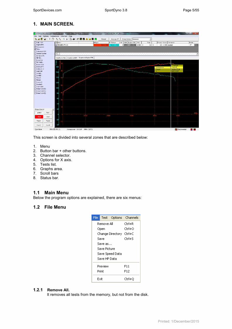
1. MAIN SCREEN.
This screen is divided into several zones that are described below: 1. Menu 2. Button bar + other buttons. 3. Channel selector. 4. Options for X axis. 5. Tests list. 6. Graphs area. 7. Scroll bars 8. Status bar.
1.1 Main Menu Below the program options are explained, there are six menus:
1.2 File Menu
1.2.1 Remove All.
It removes all tests from the memory, but not from the disk.

SportDevices.com SportDyno 3.8 Page 6/55
Printed: 1/December/2015
1.2.2 Open. It shows a window to choose the tests to be loaded in memory. It is possible to load them one by one or several at once.
1.2.3 Change directory. It allows changing the directory where tests are automatically saved.
Change Directory Window
1.2.4 Save as. It allows saving the dyno run with a different name or in a different place.
1.2.5 Save picture. It saves a picture with the current graphs area in BMP format. If you want to send it by email, it is better if you change it to gif later.
1.2.6 Export speed data. Writes a text file with the speed data of the test in CSV format (Comma Separated Values), so the data can be used with other programs, for example Microsoft Excel.
1.2.7 Export HP data. It writes a text file with data from HP and TQ in CSV format, so data can be used with other programs like Excel.
1.2.8 Preview. It shows a preview in the screen of the tests in the same way as they will appear in the printer.
1.2.9 Print. It prints the selected tests. It shows a window so you can first choose and configure the printer.
1.2.10 Exit. The program will be closed.

SportDevices.com SportDyno 3.8 Page 7/55
Printed: 1/December/2015
1.3 Test Menu.
1.3.1 Run (F5).
It opens the ‘Gauges’ Window. In this window you can input the data for the dyno run and the environmental conditions. Then, you can start the test by clicking over the ‘Start’ button in this window or the start button at the dyno.
First click will show this window, second click will start test, third click will finish the test.
1.3.2 Test ratio (F7). This option opens the “Ratio” Window which is used to calculate the Engine RPM / Roller RPM ratio using the vehicle’s Engine RPM Gauge, when the engine RPM channel is not available.
In this window you can input the rpm value at which you will do the test.
Normally the test is performed with last gear (say 5th or 6
th), although in some vehicles
you may need the previous gear (4th or 5
th). The procedure consists of accelerating the
engine up to it reaches the selected RPM value (for example 6000) and then press Continue” Button (or the start/stop in the dyno).
1.3.3 Hide Negative Part. It hides all channels during the coasting phase (ex. Lambda), in this way channels are only shown where the engine/vehicle is providing power and torque, and they are not “overwritten” when the engine RPM goes back (which normally is confusing).
1.3.4 Calculate Power Curve with Losses. It calculates the addition of wheel power + friction losses, and displays the result instead of the real power curve. It is important to keep in mind that that calculation is only an estimation of the real power.
1.3.5 Histogram. It performs a statistical analysis in which can be seen the predominating RPM/KMH ratio of the test. The program makes automatically a histogram after doing a dyno run when the “using rpm clamp” option has been chosen.
1.3.6 Make average. This option is useful to make an average between tests of the same vehicle, typically consecutive tests, to get a new test with the averaged power and torque.
It shows a window to choose which tests to average, and it creates a new test from them. It is needed to have loaded at least two tests.

SportDevices.com SportDyno 3.8 Page 8/55
Printed: 1/December/2015
1.3.7 Calculate Slip % As the wheel applies torque over the roller, certain slip percentage is produced (proportional to torque). This option creates a calculated channel from roller rpm channel and engine rpm channel to see the slip percentage at each point. Actual HP could be calculated by adding the slip percentage at the maximum HP point, but it is not a reliable process to be automated by the program.
In order that the slip% calculation is accurate, the user must know the exact ratio without torque. Thus a no-acceleration test is strongly recommended in order to get the actual gearbox ratio, at steady rpm. Then, by using this ratio a normal dynorun will be performed. And slip% could be calculated from a consistent ratio that starts from slip%=0 when no torque is applied.
You can also try to compensate the current ratio with this window, but this is only an approximate way to do it:
1.3.8 Filter RPM Channel. This option removes some "glitches" at RPM channel, but not always it can be done. Nevertheless, SportDyno software use engine RPM channel in a statistic way to determine ratio between engine RPM and speed of Roller, so few glitches at the channel do not affect the Ratio, HP and TQ calculations. (Ratio is calculated only when Roller accelerates, so rpm channel is not used when the Engine decelerates)
1.3.9 Filter Analog Channel. This option performs a low-pass filter to the selected channel to remove high-frequency noise. The size of the filter can be entered between 1 to 30.
This operation is not undo-able.
1.3.10 Generate RPM Channel. This option recalculates the entire engine RPM channel overwriting the previous values with its calculated ones. This new values are the result of multiplying speed channel by Ratio value, thus if ratio value is wrong, resulting RPM channel will be wrong too.
This option is only useful to generate a calculated rpm channel when it wasn’t recorded, but keep in mind that this channel is fake, and could not match with the true oneQ
1.3.11 Add / Modify Channel. This option adds or modifies a calculated channel to the current test. Calculated channels are selected from the total channel list, and a calculation formula is used to generate the channel. For more information please refer to section 13.

SportDevices.com SportDyno 3.8 Page 9/55
Printed: 1/December/2015
1.3.12 Remove Channel. This option removes the current selected channel from the current test. It can be used for either removing normal channels or calculated channels. Please be careful, once a normal channel there is no “undo” option to recover it.
1.3.13 Remove Test. It removes the selected dyno-run from memory (not from the disk).
1.3.14 Delete Test. It deletes the dyno-run from memory and from the DISK. Be careful.
1.3.15 Properties. It shows all data from the test in a new window (the same data as in the dyno runs list). This window allows the user to change certain values (such as ratio, temp, etc) after doing a dyno run.
1.4 Options Menu
1.4.1 Configuration. This option opens the (main) Configuration Window, it’s explained below.
1.4.2 Throttle Configuration [NEW] It opens the Throttle Configuration Window. Please refer section 11.
SportDevices.com SportDyno 3.8 Page 10/55
Printed: 1/December/2015
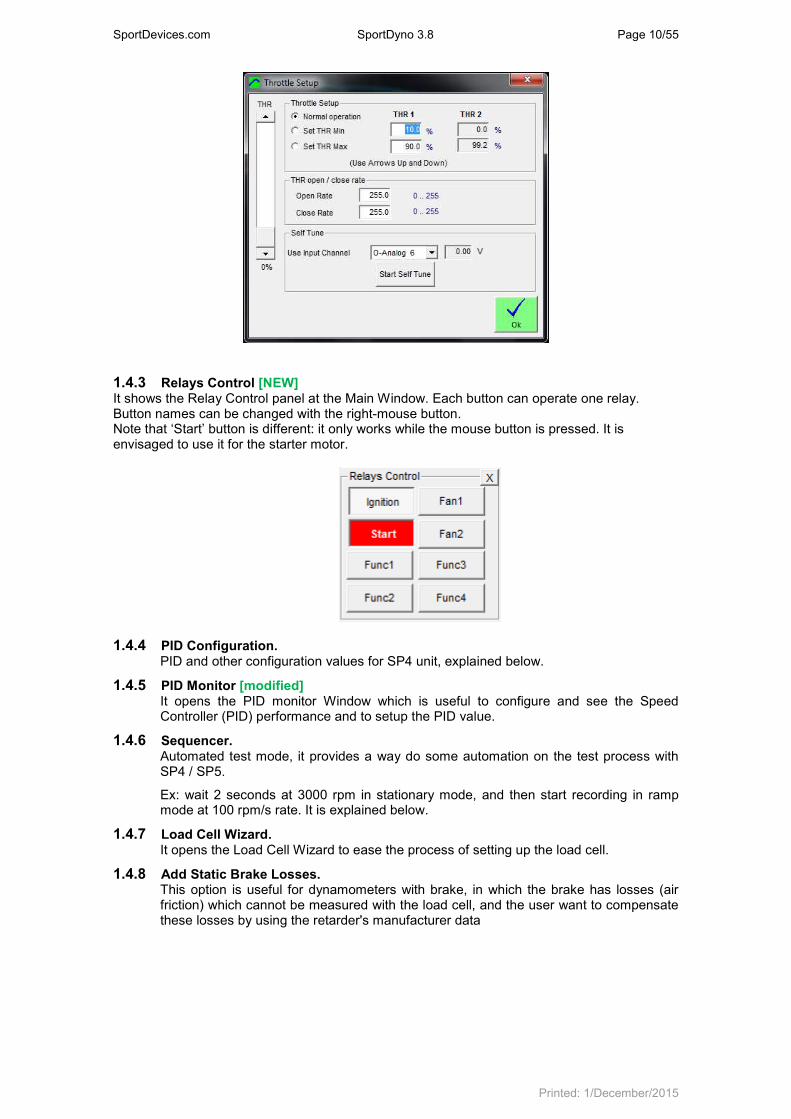
1.4.3 Relays Control [NEW] It shows the Relay Control panel at the Main Window. Each button can operate one relay. Button names can be changed with the right-mouse button. Note that ‘Start’ button is different: it only works while the mouse button is pressed. It is envisaged to use it for the starter motor.
1.4.4 PID Configuration. PID and other configuration values for SP4 unit, explained below.
1.4.5 PID Monitor [modified] It opens the PID monitor Window which is useful to configure and see the Speed Controller (PID) performance and to setup the PID value.
1.4.6 Sequencer. Automated test mode, it provides a way do some automation on the test process with SP4 / SP5.
Ex: wait 2 seconds at 3000 rpm in stationary mode, and then start recording in ramp mode at 100 rpm/s rate. It is explained below.
1.4.7 Load Cell Wizard. It opens the Load Cell Wizard to ease the process of setting up the load cell.
1.4.8 Add Static Brake Losses. This option is useful for dynamometers with brake, in which the brake has losses (air friction) which cannot be measured with the load cell, and the user want to compensate these losses by using the retarder's manufacturer data

SportDevices.com SportDyno 3.8 Page 11/55
Printed: 1/December/2015
1.5 Connections
1.5.1 Auto Detect. It shows the Auto-COM-search window. It is strongly recommended for USB adaptors where the COMxxx can be any number between COM1 and COM255.
1.5.2 COM1 - COM(n). It selects the serial port in which the SPx module is connected. If a port fails, it will be shown grayed. If there is not any available port, it is recommended to close all programs and open SportDyno again.
Everytime the Auto Detect option is clicked, this COMs list is updated, this allows to display new COMs when a new USB adapter has been connected.
1.5.3 Reconnect [NEW] If this option is active, when the connection is lost, Sportdyno will re-try the connection every few seconds. This allows disconnecting and connecting USB adapters in case Windows removed the adapter driver, or in case of TCP connections, it allows to plug the Ethernet connector and Sportdyno will create the connection automatically.
1.5.4 USB Weather Station [NEW] This option opens the Weather Station window. This window allows choosing the COM port for the Weather Station, and also performing an automatic search for the W.S. (magnifying glass button).
SportDevices.com SportDyno 3.8 Page 12/55
Printed: 1/December/2015
This window also allows adding correction offsets for temperature, humidity and pressure (adds or subtracts), although normally this is not necessary as Weather Station uses a high quality Bosch sensor for Temperature and Pressure.
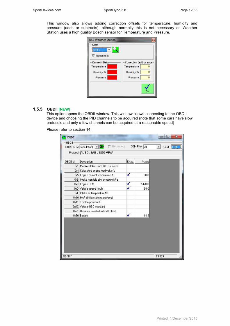
1.5.5 OBDII [NEW] This option opens the OBDII window. This window allows connecting to the OBDII device and choosing the PID channels to be acquired (note that some cars have slow protocols and only a few channels can be acquired at a reasonable speed)
Please refer to section 14.

SportDevices.com SportDyno 3.8 Page 13/55
Printed: 1/December/2015
1.6 Channels Menu.
1.6.1 Channel Settings. It shows the channels configuration window. Channel name can be changed in this screen so the name matches to the function that channel performs in your dyno, for example: channel 0x4A (former ‘J’): ‘Sensor 1’, could be named as ‘Lambda 1’. Also, you can modify the scale data of the sensor, and decimal places.
1.6.2 Activation / Raw data. It shows a Channels Window useful to see the incoming data from the SPx box (to see if there is any fault)
1.6.3 Alarms. It shows the Alarms configuration window. Alarms are useful to detect hazard situations especially on Engine test bed dynos that could be working for hours without the operator surveillance.
1.7 Help Menu
1.7.1 About. It shows information about SportDevices, developer of the software and SPx module manufacturer.
1.8 Button Bar
By clicking over these buttons you can do more quickly the same actions that using the menu. Options are: Shinning sheet: New. File/new menu.
Opening folder: Open. File/open menu.
Two folders: Change directory. File/change directory menu.
Disk: Save as. It saves the dyno run with another name or in another directory.
“Play” icon: Run. Test/run menu. (F5 key)
Gauge: Test Ratio. Test / ratio calculation menu.
Glass +: Zoom +. It magnifies the graphs area x 2.
Glass -: Zoom -. It reduces the graphs area / 2.
Round arrow: Redraw. Draws again the dyno runs, and also calculates again the scales (if not in manual mode)
Scissors: Cut-end-of-the-test. When using this option, the user will click over a certain part of the test (in graphs vs time mode) then the program will discard the final part of the test from the point where the user clicked to the end of the test.

SportDevices.com SportDyno 3.8 Page 14/55
Printed: 1/December/2015
Sheet and glass: Preview. File/preview menu (F11 key)
Print. File/print menu (F12 key)
Tools. It opens program configuration window.
Graphs: Channels. It opens channel configuration window.
Load Cell Wizard. It shows the Load Cell Wizard window.
Exclamation sign: It opens the Alarms window.
Yellow Label. It shows/Hides data label. This label shows certain information from the chosen channel while the user moves the cursor across the tests.
Gray and Black blocks: It changes the window arrangement: In vertical arrangement, all small frames (channels, relay buttons) are displayed at left side. In horizontal arrangement all small frames are displayed on top to allow the graphs to take the whole Window width.
SportDevices Icon: About. Help / About menu.
Manual. Manual mode is useful to set a fixed Time, speed (1) or Rpm (2) scales regardless of the test values. It could be useful if some strange data is present on the test and you want to force known limits. The rest of scales (HP, TQ, and the rest of channels) have been removed from this window and have been added on the channel configuration window, by using the upper bound and lower bound fields.
• Manual checkbox activates the manual mode. Once activated, the button on the main window changes its colour to show you manual mode is active.
• Block Scroll and Zoom checkbox disables the mouse tracking and moving over the graphs.
HP average. This option is used to calculate average power inside a rpm range or a time range. The option has been moved from main configuration to this independent window to ease its use. It has three modes: OFF, RPM range and time range. When activated, two small vertical lines will be displayed showing the selected range and a doted horizontal line crossing at the HP power value. This calculated value is also available in the test data area. The column is hidden by default, but the user can enable it with the right button of mouse.
SportDevices.com SportDyno 3.8 Page 15/55
Printed: 1/December/2015
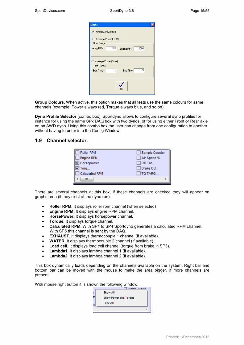
Group Colours. When active, this option makes that all tests use the same colours for same channels (example: Power always red, Torque always blue, and so on) Dyno Profile Selector (combo box). Sportdyno allows to configure several dyno profiles for instance for using the same SPx DAQ box with two dynos, of for using either Front or Rear axle on an AWD dyno. Using this combo box the user can change from one configuration to another without having to enter into the Config Window.
1.9 Channel selector.
There are several channels at this box, if these channels are checked they will appear on graphs area (if they exist at the dyno run):
• Roller RPM. It displays roller rpm channel (when selected)
• Engine RPM. It displays engine RPM channel.
• HorsePower. It displays horsepower channel.
• Torque. It displays torque channel.
• Calculated RPM. With SP1 to SP4 Sportdyno generates a calculated RPM channel. With SP5 this channel is sent by the DAQ.
• EXHAUST. It displays thermocouple 1 channel (if available).
• WATER. It displays thermocouple 2 channel (if available).
• Load cell. It displays load cell channel (torque from brake in SP3).
• Lambda1. It displays lambda channel 1 (if available).
• Lambda2. It displays lambda channel 2 (if available). This box dynamically loads depending on the channels available on the system. Right bar and bottom bar can be moved with the mouse to make the area bigger, if more channels are present. With mouse right button it is shown the following window:

SportDevices.com SportDyno 3.8 Page 16/55
Printed: 1/December/2015
• Show All. Activates all available channels.
• Show Power And Torque. Activates only HP and TQ channels.
• Hide All. Hide all channels.
1.10 Options for X Axis.
Options in this box are: “Graphs vs. time” It displays dyno run curves as a function of time (seconds). “Graphs vs. KMH/MPH” (for vehicle dynos) or “Graphs vs. Roller RPM” (for engine dyno)
It displays dyno run graphs as a function of roller RPM/Speed “Graphs vs. Engine RPM” It displays test curves as a function of engine RPM. This channel
is always calculated by using the ratio value (RPM/KMH) of dyno run, so this scale will be wrong if ratio is wrong. Note: Automatic engines should not be displayed in this mode, because the gearbox ratio or CVT changes while the roller accelerates.
1.11 Dyno run List
This list contains tests loaded from the disk or tests done with the dyno. By right-clicking over the test list, a popup window will be displayed to ease certain functions related with the test. Behaviour of these functions is the same as on the Test Menu.
From version 3.3 the user can change directly most data over the list, to do this you can press key F2 or click twice over the desired cell. Note: gray cells cannot be edited. If you right-click over the Titles row then a popup menu will be displayed. This menu contains all available columns. Here you can check / uncheck over them in order the columns will be displayed on the list or not.
SportDevices.com SportDyno 3.8 Page 17/55
Printed: 1/December/2015
Columns: View. By clicking over this column a check mark will appear/disappear, making the test being
displayed / hidden on the main window. Name. Name of dyno run, if name is changed and then ENTER is pressed the file on the disk
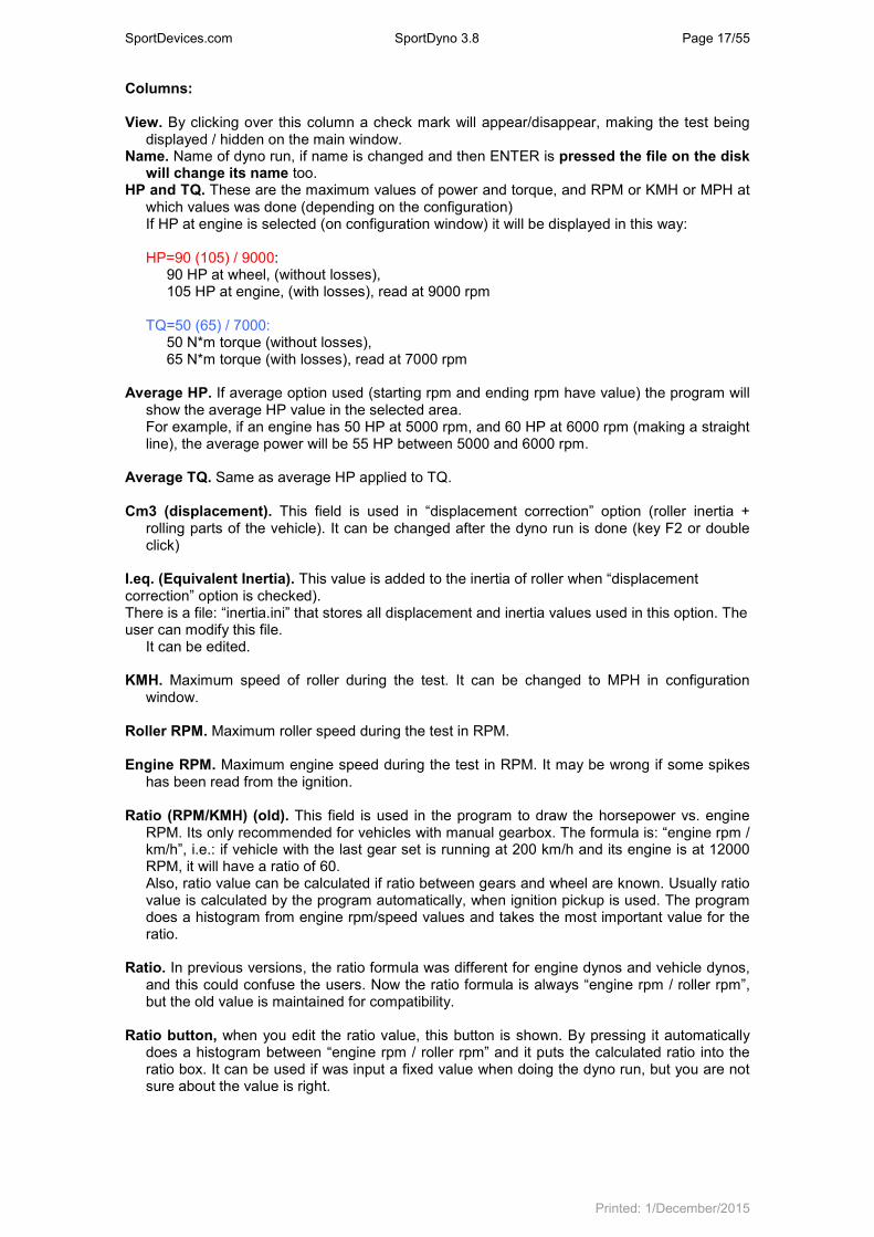
will change its name too. HP and TQ. These are the maximum values of power and torque, and RPM or KMH or MPH at
which values was done (depending on the configuration) If HP at engine is selected (on configuration window) it will be displayed in this way:
HP=90 (105) / 9000:
90 HP at wheel, (without losses), 105 HP at engine, (with losses), read at 9000 rpm
TQ=50 (65) / 7000: 50 N*m torque (without losses), 65 N*m torque (with losses), read at 7000 rpm
Average HP. If average option used (starting rpm and ending rpm have value) the program will show the average HP value in the selected area. For example, if an engine has 50 HP at 5000 rpm, and 60 HP at 6000 rpm (making a straight line), the average power will be 55 HP between 5000 and 6000 rpm.
Average TQ. Same as average HP applied to TQ. Cm3 (displacement). This field is used in “displacement correction” option (roller inertia +
rolling parts of the vehicle). It can be changed after the dyno run is done (key F2 or double click)
I.eq. (Equivalent Inertia). This value is added to the inertia of roller when “displacement correction” option is checked). There is a file: “inertia.ini” that stores all displacement and inertia values used in this option. The user can modify this file.
It can be edited.
KMH. Maximum speed of roller during the test. It can be changed to MPH in configuration window.
Roller RPM. Maximum roller speed during the test in RPM.
Engine RPM. Maximum engine speed during the test in RPM. It may be wrong if some spikes has been read from the ignition.
Ratio (RPM/KMH) (old). This field is used in the program to draw the horsepower vs. engine RPM. Its only recommended for vehicles with manual gearbox. The formula is: “engine rpm / km/h”, i.e.: if vehicle with the last gear set is running at 200 km/h and its engine is at 12000 RPM, it will have a ratio of 60. Also, ratio value can be calculated if ratio between gears and wheel are known. Usually ratio value is calculated by the program automatically, when ignition pickup is used. The program does a histogram from engine rpm/speed values and takes the most important value for the ratio.
Ratio. In previous versions, the ratio formula was different for engine dynos and vehicle dynos, and this could confuse the users. Now the ratio formula is always “engine rpm / roller rpm”, but the old value is maintained for compatibility.
Ratio button, when you edit the ratio value, this button is shown. By pressing it automatically does a histogram between “engine rpm / roller rpm” and it puts the calculated ratio into the ratio box. It can be used if was input a fixed value when doing the dyno run, but you are not sure about the value is right.
SportDevices.com SportDyno 3.8 Page 18/55
Printed: 1/December/2015
Temperature, Humidity, Pressure. Weather conditions are stored with the dyno run when is done. They are important because “temperature correction” option uses them. If changed after doing test, HP and TQ values will change too.
Correction factor. Depending on the chosen correction type, the program will calculate automatically this value. This value can be edited, and once you have changed it, the program won’t recalculate it again. But if you want the program recalculates it, you only have to delete the number and press enter, then the program will calculate it again as a function of temperature, humidity, air pressure and correction type.
Correction Type. There are several correction formulas available:
• Blank (none)
• ISO 1585
• SAE J1349
• DIN 70020
• JIS D1001
• EC95-1
• FIXED
The program will use the correction type of the configuration window as default, but you can change it after the test is done
Time offset. This value has been added to the dyno run to enable comparison between tests
when graphs are displayed vs. time, because the starting point of each test is not always the same. By changing this value all the test will be displaced later in time (positive values) or displaced before in time (negative values)
Comments. Comments are stored with the test. If editing the comment there will be displayed a button at the right of the box of the comment (...). By clicking the button it will show a window in which comments can be written in several lines.
Date / Time when the test was done.
Weight of vehicle. At the moment this field is only informative, but could be used for acceleration calculation purposes in future.
Channels recorded in the test. For example: 01AJ: 0-roller, 1-engine RPM, A-thermocouple, J-lambda.
Diameter of the roller used to do the test. The program uses it when calculating HP and TQ. It can not be edited.
Number of teeth used to do the test. The program doesn’t use it once the test is saved. It can
not be edited. Prescaler used on the test. The program doesn’t use it once the test is saved. It can not be
edited. Inertia of the roller / flywheel. The program uses it when calculating HP and TQ. It can be
edited if you have entered it wrong. Samples taken by the SP1 / SP3 for the main channel. Future versions will have channels at
different speeds. Time spent on the dyno run. This value has no relationship with the acceleration of the
engine. You can do a test of 5 seconds and then wait 30 seconds before stopping the test, and then the test will be 35 seconds long.
Class of dyno where the test was done (vehicle or engine).
Filename. Full file name and path of the test.

SportDevices.com SportDyno 3.8 Page 19/55
Printed: 1/December/2015
Changed. It will be ‘*’ if the test was changed. If using “automatic saving” the test will be saved
and this filed will be blank again.
1.12 Graphs Area In this area are shown the curves from the channels of the different tests loaded in memory (power, torque and rpm).
At the left side of the curves, are shown the scales:
Engine rpm (green) Horsepower (red) Torque (blue). X axis at the bottom shows the selected scale (time, roller RPM, km/h or engine RPM) The scale from the selected channel (torque at the example) is displayed to the left side, close the curves area. All drawing lines of the area are drawn using the same colour. To show/hide any test only it is needed to click over the first column on the list of tests at the desired test. By right-clicking over the scale area, it is shown the scale channel menu. In this menu can be chosen which channels will be displayed at scales. But only will be shown scales from enabled channels (on channel selector)
By right-clicking over the graphs area, it is shown a list with the loaded tests (and the selected one) and a list of the channels included in the current test (and the selected one) You can change the selected test or the selected channel in this lists.

SportDevices.com SportDyno 3.8 Page 20/55
Printed: 1/December/2015
Arrow, zoom +, zoom –, and move options have been removed from here and assigned to the mouse’s wheel and left button. Also, save picture option has been added. The same as on file menu.
1.13 Scroll Bars When zoom is used, the user can change the graph position by using the “move” option or by using the scroll bars (at bottom and right side of the window).
1.14 Status Bar
This area shows:
• Number of loaded tests
• Name of selected test
• Name of selected channel,
• Values from selected channel, while the mouse moves over the graphs area,
• Status messages,
• Whether SPx module is connected or not.
• Weather Station Status
• OBDII Status

SportDevices.com SportDyno 3.8 Page 21/55
Printed: 1/December/2015
2. GAUGES WINDOW
2.1 Gauges’ area.
This window is user configurable. The user can add new controls: Gauges, Thermometers, Numeric boxes or Scroller type windows. If you right click over any control a popup menu will appear.
Options are:
• Add new Control: o Gauge, o Temp, o Box, o Scroller Once the control is on the screen, the user can move it to the desired position, and change its properties, and assigned channel.
• Remove Box: user can remove any of the current controls on the screen.
• Bring to Front: user can move a control over all others on the screen.
• Bring to Back: user can move a control over all others on the screen.
• Background [NEW]: o Default (carbon fiber effect) o Plain colour: will show a colour selection window o Bitmap: allows to load a BMP file for the background

SportDevices.com SportDyno 3.8 Page 22/55
Printed: 1/December/2015
• Style: It changes the default colours for all controls o Cyan o Yellow o Blue
• Configuration: Open / Save [New] It allows to save the current layout of Gauges window, and load it from a file
• Box properties: with this option a properties window will be shown. This window lets you to change certain data from the control.
In this window you can change the size of the control (Gauge and Scroller only), the colour used for numbers, the assigned channel, and maximum value, factor (scale) and decimals (from channel configuration). Upper bound and lower bound can be used on gauge control (for example for lambda: from 9 to 14) and Scroller control. Note that not only SPx unit channels can be also added here, but also channels from: Calculated channels, Weather Station and OBDII.
2.2 Test data area This window is used to enter the test data and to setup the way the test will be done. In the current version it has been splitted into four tabs to group the data by its function and to allow more data and options are available.
2.2.1 Test Data
- Test Name, this name will be the same that it will be saved to disk. Name will be “incremented” every new test (TEST_001, TEST_002 Q)
- Engine Displacement, on vehicle dynos, the program will calculate an equivalent inertia to correct the power (if this compensation is enabled at main screen),
- Equivalent Inertia, this inertia value is added to the dyno’s inertia in order to compensate the inertia from wheels, gearbox, etc.
- Weight, is an informative value, it is not used on calculations. - Clear commentaries each new test, the program will keep the commentaries from the
last test by default. With this option you can clear them automatically.

SportDevices.com SportDyno 3.8 Page 23/55
Printed: 1/December/2015
2.2.2 Engine RPM
• Usign RPM Clamp: Sportdyno will use the Engine RPM channel to calculate the Ratio value, which is used for Torque at Engine calculation (only Torque at Roller is known), and for displaying the Engine RPM X axle (on graphs vs Engine RPM mode)
• Fixed Ratio: If Ratio value is known (for instance on engine dynos using sprockets) , or after determining Ratio on Ratio Window.
o Simulate RPM: as most times that Fixed Ratio is used, Engine RPM channel is not available, then this option is used to display the calculated RPM, which are the same that SP4 and SP5 use for the speed control (speed control is not performed using Engine RPM)
• Test Ratio: it opens the Ratio Window to determine Ratio value, and then it comes back to Gauges Window.
2.2.3 Weather Data
- Type of Compensation. There are several compensation methods available: - Blank (none) - ISO 1585 - SAE J1349 - DIN 70020 - JIS D1001 - EC95-1 - FIXED (here the user can set the fixed correction factor)
By default the program will take the compensation from the configuration, and then the user can change it for each particular test. The program shows in the grey box the current compensation factor for the current weather conditions.
- Weather conditions: Air Temperature, Humidity and Pressure. These values are used
to correct horsepower and torque.
- Air Density. It is calculated by Sportdyno, just for information purposes.
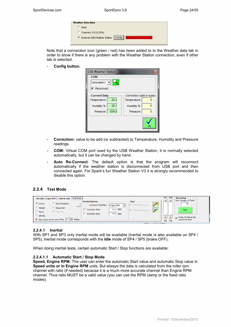
- Weather Data Auto. This option lets you to automate the weather data acquisition. By default data has to be entered by hand, but by using an external USB Weather Station or the 3 last SP4 analog channels (with the suitable sensors) the weather data can be acquired automatically. Data is shown in real time, if one of those modes is selected.
When using USB Weather Station press over the red box (“disconnected click here”) to perform the automatic search of virtual COM port.
SportDevices.com SportDyno 3.8 Page 24/55
Printed: 1/December/2015
Note that a connection icon (green / red) has been added to to the Weather data tab in order to show if there is any problem with the Weather Station connection, even if other tab is selected.
- Config button.
- Correction: value to be add (or subtracted) to Temperature, Humidity and Pressure readings.
- COM: Virtual COM port used by the USB Weather Station, it is normally selected automatically, but it can be changed by hand.
- Auto Re-Connect: The default option is that the program will reconnect automatically if the weather station is disconnected from USB port and then connected again. For Spark’s fun Weather Station V3 it is strongly recommended to disable this option.
2.2.4 Test Mode
2.2.4.1 Inertial With SP1 and SP3 only inertial mode will be available (inertial mode is also available on SP4 / SP5), Inertial mode corresponds with the Idle mode of SP4 / SP5 (brake OFF). When doing inertial tests, certain automatic Start / Stop functions are available: 2.2.4.1.1 Automatic Start / Stop Mode Speed, Engine RPM: The user can enter the automatic Start value and automatic Stop value in Speed units or in Engine RPM units. But always the data is calculated from the roller rpm channel with ratio (if needed) because it is a much more accurate channel than Engine RPM channel. Thus ratio MUST be a valid value (you can use the RPM clamp or the fixed ratio modes)

SportDevices.com SportDyno 3.8 Page 25/55
Printed: 1/December/2015
2.2.4.1.2 Automatic start If this option is selected, the dyno run will start when Engine RPM is greater than the value set at the right (6000 rpm)
Mode of operation: when button is pressed, "gauges" window will appear as usually. If you press again the button a second frame will appear (with automatic start activated). This frame tells you "accelerate to max rpm".
If Engine RPM is higher than the starting rpm value the "semaphore box" will be red, and dyno run won’t start. When engine downs to a lower rpm, the "semaphore box" will be green. Then, when you give full throttle and RPM are higher than the starting rpm value, dyno run will begin.
2.2.4.1.3 Automatic stop Here the stop rpm value is entered. There are two possibilities to determine when to stop: when engine has reached the stop value, or when the test is in the losses / coasting stage and engine reaches down the stop value. 2.2.4.1.4 Stop Mode In vehicle dynamometers, when doing a dyno run, you accelerate the engine near its maximum rpm, then clutch is pressed to leave the roller decelerate slowly, and when roller speed is lower than the “ending rpm” value (applying ratio) the test will stop automatically. Here you will use “stop when lower” stop mode. In engine dynamometers (if no clutch is available), when accelerating the engine near its maximum rpm, you will finish the test as soon as the selected max rpm value is reached. Here you will use “Stop When Higher” stop mode. These modes are provided here regardless the type of dynamometer so you can choose the mode you need for the tests you are doing. 2.2.4.2 Steady This mode is only available with SP4 unit.
It will enter automatically the SP4 / SP5 in Steady mode, and will update the RPM Target when changing the “Target RPM” box, or when using the page up and page down keys. When a test is recorded in this mode, target rpm remains constant for the whole test. Steady-then-inertial. [NEW] In some cases the user needs to have the engine steady and full loaded before starting an INERTIAL test, then use Steady mode, and click on this option. The SP4 / SP5 will remain in steady mode before starting the test (for instance to load turbocharger), and when the recording is started it will perform an inertial test. Note: as the brake is still braking for the first second of test (or more) due to its remaining magnetic field, the test is computed as a Steady Test, and Load Cell is considered as if it was a braked test.

SportDevices.com SportDyno 3.8 Page 26/55
Printed: 1/December/2015
2.2.4.3 Ramp This mode is only available with SP4 / SP5 unit.
It will enter automatically the SP4 / SP5 in Steady Mode, and will update the RPM Target when changing the “Min RPM” box, or when using the Page Up and Page Down keys. This lets you to get the engine steady and full loaded before starting the test. The user should set the Ending RPM and Test Time before starting the test (Accel Slope is calculated from these 3 values). “Stop when lower” and “Stop when higher” work in the same way as on inertial mode. After the test starts, the program will enter automatically the SP4 / SP5 in Ramp (Sweep) Mode in order to start to increase the Target RPM as the engine accelerates. Slow Down at the End of the Test. This option uses a negative accel rate to decrease the speed of the roller until it reaches the starting Min RPM. It is useful on Engine Test bed specially when there is a clutch between engine and brake (typically with 2 strokes), but also on car dynos, because braking the car (with the car’s brakes) can make it move backwards due to the inertia of the rollers.
2.2.5 Common area
Throttle slide bar [NEW], this allows to control the throttle while preparing the test (envisaged for Engine Test bed dynos) Brake slide bar [NEW], this allows to control the brake either after a dyno run (to slow down the roller), before a new run, or just to test the brake. Max number of tests, (in older versions: “remove last tests”), this box (at the bottom-right side), indicates to the program the maximum number of dyno runs loaded at memory each time a new dyno run is done, it will remove the older tests if there are more. It is useful when a lot of test are being done, for example to allow one alone person to use the dyno. It prevents to accumulate a big quantity of curves at screen. Start Button, it will start a new test (see next section “How to do a dyno run”) Close Throttle after the end of the Test bar [NEW]. This option automatically closes the throttle when the test recording ends. It is envisaged for Engine Test bed dynos.
SportDevices.com SportDyno 3.8 Page 27/55
Printed: 1/December/2015
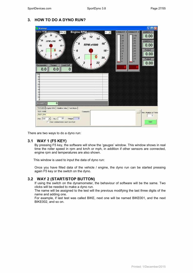
3. HOW TO DO A DYNO RUN?
There are two ways to do a dyno run:
3.1 WAY 1 (F5 KEY) By pressing F5 key, the software will show the ‘gauges’ window. This window shows in real time the roller speed in rpm and km/h or mph, in addition if other sensors are connected, engine rpm and temperatures are also shown.
This window is used to input the data of dyno run: Once you have filled data of the vehicle / engine, the dyno run can be started pressing again F5 key or the switch on the dyno.
3.2 WAY 2 (START/STOP BUTTON) If using the switch on the dynamometer, the behaviour of software will be the same. Two clicks will be needed to make a dyno run. The name will be assigned to the test will the previous modifying the last three digits of the name and adding one. For example, if last test was called BIKE, next one will be named BIKE001, and the next BIKE002, and so on.
SportDevices.com SportDyno 3.8 Page 28/55
Printed: 1/December/2015
4. RATIO WINDOW
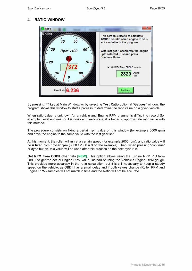
By pressing F7 key at Main Window, or by selecting Test Ratio option at “Gauges” window, the program shows this window to start a process to determine the ratio value on a given vehicle. When ratio value is unknown for a vehicle and Engine RPM channel is difficult to record (for example diesel engines) or it is noisy and inaccurate, it is better to approximate ratio value with this method. The procedure consists on fixing a certain rpm value on this window (for example 6000 rpm) and drive the engine to the same value with the last gear set. At this moment, the roller will run at a certain speed (for example 2000 rpm), and ratio value will be = fixed rpm / roller rpm (6000 / 2000 = 3 on the example). Then, when pressing “continue” or dyno button, this value will be used after this process on the next dyno run. Get RPM from OBDII Channels [NEW]. This option allows using the Engine RPM PID from OBDII to get the actual Engine RPM value, instead of using the Vehicle’s Engine RPM gauge. This provides more accuracy in the ratio calculation, but it is still necessary to keep a steady speed on the vehicle, as OBDII has a small delay and if both values change (Roller RPM and Engine RPM) samples will not match in time and the Ratio will not be accurate.
SportDevices.com SportDyno 3.8 Page 29/55
Printed: 1/December/2015
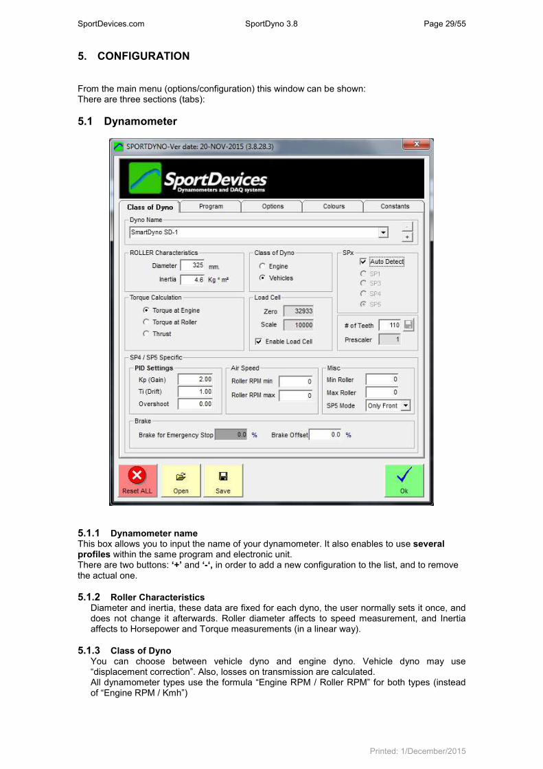
5. CONFIGURATION From the main menu (options/configuration) this window can be shown: There are three sections (tabs):
5.1 Dynamometer
5.1.1 Dynamometer name This box allows you to input the name of your dynamometer. It also enables to use several profiles within the same program and electronic unit. There are two buttons: ‘+’ and ‘-‘, in order to add a new configuration to the list, and to remove the actual one.
5.1.2 Roller Characteristics Diameter and inertia, these data are fixed for each dyno, the user normally sets it once, and does not change it afterwards. Roller diameter affects to speed measurement, and Inertia affects to Horsepower and Torque measurements (in a linear way).
5.1.3 Class of Dyno You can choose between vehicle dyno and engine dyno. Vehicle dyno may use “displacement correction”. Also, losses on transmission are calculated. All dynamometer types use the formula “Engine RPM / Roller RPM” for both types (instead of “Engine RPM / Kmh”)
SportDevices.com SportDyno 3.8 Page 30/55
Printed: 1/December/2015
5.1.4 SPx Device. Depending on the SPx unit you are using, you can select one of the three options. SP3, SP4 and SP5 use load cell. User can also left the “Auto Detect” option active, so Sportdyno identifies the SPx device type.
5.1.5 Torque Calculation By default torque calculation mode is “Torque at Engine”. The program calculates this value from the torque measured at Roller, and uses the Ratio value to do this. Keep in mind that torque at engine will depend on the ratio value. If Ratio is wrong for the dyno run, torque at Engine will be wrong too. Torque at Engine normally is lower than torque at wheel due to gearbox, transmission and tire size, because torque is increased as RPM is decreased. Torque at engine cannot be calculated on automatic transmissions. Thrust: It is a variant of torque at Roller; it provides the lineal thrust or force of vehicle over the roller. It could be used to calculate the capacity of the vehicle to go up on a slope. It does not depend on ratio.
5.1.6 SPx configuration
We recommend using a gear tooth between 8 and 150 teeth. For a gear tooth of 110 teeth, use a prescaler = 16. Number of teeth: number of teeth at gear used on roller or flywheel. This gear is often used for the starter motor too. Prescaler: this feature adapts the digital input (up to 15 KHz) to the capacity of SP1 to SP4 units (up to 1 KHz). Depending on the number of teeth, gear tooth will generate a different frequency at the hall sensor, and then a different prescaler has to be configured (the program will chose on by default)
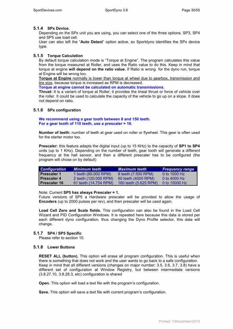
Configuration Minimum teeth Maximum teeth Frequency range
Prescaler 1 1 teeth (60.000 RPM) 8 teeth (7.500 RPM) 0 to 1000 Hz Prescaler 4 2 teeth (120.000 RPM) 60 teeth (4000 RPM) 0 to 4000 Hz Prescaler 16 61 teeth (14.754 RPM) 160 teeth (5.625 RPM) 0 to 15000 Hz
Note: Current SP5 has always Prescaler = 1. Future versions of SP5 a Hardware prescaler will be provided to allow the usage of Encoders (up to 2000 pulses per rev), and then prescaler will be used again. Load Cell Zero and Scale fields. This configuration can also be found in the Load Cell Wizard and PID Configuration Windows. It is repeated here because this data is stored per each different dyno configuration, thus changing the Dyno Profile selector, this data will change.
5.1.7 SP4 / SP5 Specific Please refer to section 10.
5.1.8 Lower Buttons RESET ALL (button). This option will erase all program configuration. This is useful when there is something that does not work and the user wants to go back to a safe configuration. Keep in mind that all different versions (changes on major number: 3.5, 3.6, 3.7, 3.8) have a different set of configuration at Window Registry, but between intermediate versions (3.8.27.10, 3.8.28.3, etc) configuration is shared Open. This option will load a text file with the program’s configuration. Save. This option will save a text file with current program’s configuration.
SportDevices.com SportDyno 3.8 Page 31/55
Printed: 1/December/2015
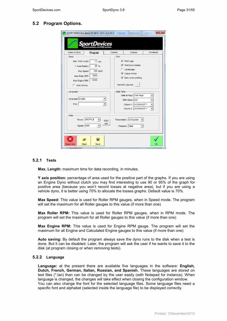
5.2 Program Options.
5.2.1 Tests
Max. Length: maximum time for data recording, in minutes. Y axis position: percentage of area used for the positive part of the graphs. If you are using an Engine Dyno without clutch you may find interesting to use 90 or 95% of the graph for positive area (because you won’t record losses at negative area), but if you are using a vehicle dyno, it is better using 70% to allocate the losses graphs. Default value is 70%. Max Speed: This value is used for Roller RPM gauges, when in Speed mode. The program will set the maximum for all Roller gauges to this value (if more than one) Max Roller RPM: This value is used for Roller RPM gauges, when in RPM mode. The program will set the maximum for all Roller gauges to this value (if more than one) Max Engine RPM: This value is used for Engine RPM gauge. The program will set the maximum for all Engine and Calculated Engine gauges to this value (if more than one) Auto saving: By default the program always save the dyno runs to the disk when a test is done. But it can be disabled. Later, the program will ask the user if he wants to save it to the disk (at program closing or when removing tests).
5.2.2 Language
Language: at the present there are available five languages in the software: English, Dutch, French, German, Italian, Russian, and Spanish. These languages are stored on text files (*.lan) than can be changed by the user easily (with Notepad for instance). When language is changed, the changes will take effect when closing the configuration window. You can also change the font for the selected language files. Some language files need a specific font and alphabet (selected inside the language file) to be displayed correctly.

SportDevices.com SportDyno 3.8 Page 32/55
Printed: 1/December/2015
Font: the user can change the Font used in the program, this is mainly interesting for languages that need a special charset as Russian Language.
5.2.3 Printer Options
Print Logo: user can select whether he wants to print the logo or not. There is a file named “logo.gif” at installation folder (C:\Program Files\Sportdevices\Sportdyno38) that can be replaced to set your own business logo. Please use a similar size file. Print Dyno Details: If active, the report will show Sportdyno SW date and version, Dyno name, and Roller inertia, and active options (displacement correction, correction factor, load cell active) Landscape: With this option dyno runs will be printed horizontally instead of. Vertically. In this way a bit less numeric data will fit on the paper. Colour printer: if not checked, printing will be optimized for black and white printers; else, graphs are printed with the same colours as on screen. Dark when printing: when printing, pure colours (red, yellow, etc) are not cleary shown over white paper. Then this option is used to dark the graphs colour over the paper. Test Info Button: the program will show Test Info fields selected in this window at report’s header. By default: Name, Power, Torque, Temperature and a few more fields are shown per each test in the first table (on page header). User can choose which test data is to be printed on the report’s header for each test (do not confuse with the test channels shown at the right table).
5.2.4 Data table Page: None, First Page or Second Page. By default graphs and numeric table are printed in a single page. Now the user can chose to not print the data table (option=none), to print it with the graph (option=First Page) or to print it in a second page (option=Second Page) RPM steps, when printing a dyno run the default RPM step is 250 for the data table, you can change this value to 100, 250, 500 or 1000 rpm. Columns 4 and 5, when printing a dyno run, the first three columns of data are: RPM (or time) HP, TQ. The next column(s) can be chosen from the rest of recorded channels of dyno run.

SportDevices.com SportDyno 3.8 Page 33/55
Printed: 1/December/2015
5.2.5 Units
Power units. You can choose between several type of units for HP and TQ, regardless International/Imperial setting
-CV (European horsepower 1CV= 0.745Kw) for power, KGM (kilograms per meter) for torque.
-KW (kilowatts) for horsepower, N*M (Newton per meter) for torque. -HP (horsepower 1HP=0.736Kw), FT*LB (feet * pound) for torque. -HP (horsepower 1HP=0.736Kw), N*M (Newton per meter) for torque.
Speed: - KMH / MPH (1 mile = 1.609 kilometers)
Temperature: - Celsius / Fahrenheit (1 fahrenheit degree= 1.8 celsius, fahrenheit starts at 32º for
celsius=0º) Pressure: - Mbar / inHg (1 mercury inch = 33.8638 mbar)
5252 RPM button: this options configures the following options to allow that HP and TQ cross at the “magic” point of 5252 RPM:
• Units are set as HP for power, and Ft*Lb for Torque. Keep in mind that 5252 RPM crossing only happens with imperial units, with other units the crossing point changes
• HP and TQ channels are set to use the “Group 1”. Channels using a group share the same scale, instead of each channel has its own scale (depending on the channels peak value). If Power has its peak at 100 HP, then Torque channel will also use 100 Ft*Lb as maximum for its scale.
5.3 Options Tab
5.3.1 Options/Messages “Warm Up” message: If activated, a “warm up” message will appear when pressing the start / stop button on the dyno (or F5 on the computer)
Show “Power at Engine”, between brackets. If checked, the program will show the wheel power value, and power + losses between brackets. The same is applied to torque. Example: HP = 55.4 (67.9) / 9000 Use “Sum” method for losses calculation. There are two methods to calculate power at engine:
• Peak Method: Calculating the Wheel’s Power Peak value (for instance 100 HP at 5000 RPM), and then adding the losses for the same RPM point (for instance 20 HP at 5000 RPM)
• Sum Method: First adding power and losses sections, and then calculating the peak for the sum. For instance at some point wheels power is 99 HP, but losses is 22 HP, then peak for sum is 101 HP.
Both methods normally will not give the same result. This option is provided to use always the “sum” method, regardless of whether the graphs are displayed with the negative section, or are added in the screen.
Use latest open file’s folder to save new tests. This option when active changes the internal file path to the latest folder in which the user open some file. If not active path is not changed, and can be kept the same during all program execution.
Enable Secondary Test. When enabling this option the program will display the information for the last two selected tests, and the delta (difference) between them.

SportDevices.com SportDyno 3.8 Page 34/55
Printed: 1/December/2015
5.3.2 Special Keys RPM Step. In Gauges and PID monitor windows, when the cursor is at Target RPM, the user can use Page Up and Page Dn keys to quickly make this value to go up and down. This field determines the amount to increase/decrease the Target Value. Invert PgUp/PgDn. With some keyboards it may be more intuitive use these keys in the opposite way. Brake key. User can define a key to activate the brake mode (to slow down the dyno). This key can be set to “none”, ”Pause key”, “F8 key”. When this mode is active, the latest brake value is used. Be careful to not have excessive braking specially when clutch is still engaged. Advanced options. See 5.6 section.
5.3.3 Filtering Roller Filter. This filter can be used when the Roller signal is not stable and due to vibrations or imperfections in the gear tooth, the speed signal has ups and downs. These oscillations will cause that in graph vs speed modes (Speed and Engine RPM) it will be shown small loops in the graph caused by these changes on speed up and down. This filter only affects to graphs and speed/RPM calculations, it is not used for power calculation. Graph Filter. This filter is applied to Power and Torque graphs in order to remove high frequency noise and low frequency mechanical oscillations. On large dynos (car), or dynos with high vibrations it can be also necessary to use the “Low Pass x 2” option. Note that the program shows an informative window that explains for each filter setting what is the minimum recommended test duration (acceleration phase) in order to not lose information about power and torque. For instance for a filter of 19 (and Low Pass OFF) minimum acceleration time should be 3.47 seconds. If acceleration duration is below this time, then accuracy is not warranted to have less than 1% error (nominal accuracy) Low Pass Filter x2. This option is used for large dynos (car) or on with high vibrations. And normally it should not be used on inertial dynos (as tests are shorter). It makes that the filter width is twice its original size, which allows to remove low frequency (mechanical) vibrations. It affects to the estimated test duration time making it twice the original value. For instance for filter=19, time without “low pass x2” is 3.47 sec, but with “low pass x2” it is 6.94. This makes it recommended only on braked dynos, and makes that minimum recommended test time is 10 seconds (for Ramp mode)
Glitch Filter. This option will filter short glitches (spikes) in the load cell channel. Thermocouple input Filter. This value is used to filter the thermocouple inputs (8) with a low-pass filter at the input. Data will be recorded after the filter. The higher the value, the higher the filtering.
SportDevices.com SportDyno 3.8 Page 35/55
Printed: 1/December/2015
Analog input Filter. This value is used to filter the analog inputs (8) with a low-pass filter in the input. Data will be recorded after the filter. The higher the value, the higher the filtering.
5.3.4 Corrections
Displacement correction. This is a correction based on the whole inertia of the vehicle and dyno (roller + wheel + transmission + gearbox) as a function of the engine displacement. If activated, this correction will be applied to all loaded tests. This option is not stored with the test, but with the program.
Correction type. There are several correction formulas available:
• Blank (none)
• ISO 1585
• SAE J1349
• DIN 70020
• JIS D1001
• EC95-1
• FIXED (here the user can set the fixed correction factor) If changed on the configuration, the program will ask you if you want to change to all loaded tests.
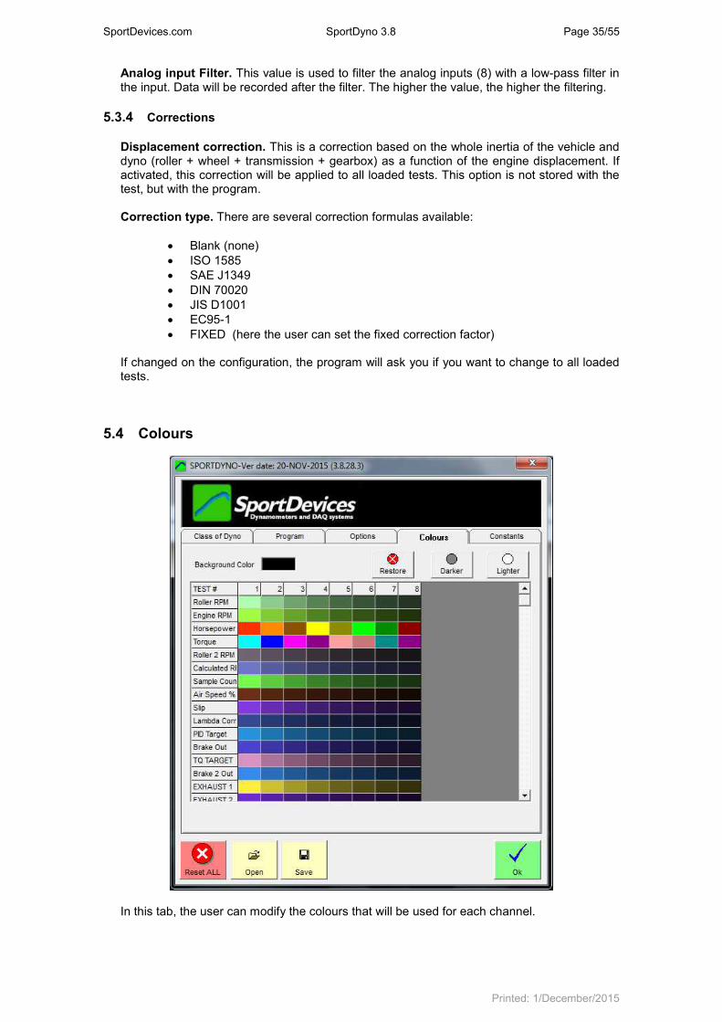
5.4 Colours
In this tab, the user can modify the colours that will be used for each channel.

SportDevices.com SportDyno 3.8 Page 36/55
Printed: 1/December/2015
To modify a colour, double-click over it and then a colour selection window will appear. Select a colour and press OK button.
You can also change the background colour for the main window. Dark and Light buttons will dark and light an entire row, all colours for the selected test. Restore will reload ALL entire default colour configuration (note that most colours are random).
5.5 Constants
In this tab, the user can setup some constants to be used with the Calculated Channels feature (see section 13)

SportDevices.com SportDyno 3.8 Page 37/55
Printed: 1/December/2015
5.6 Advanced Options Normally user does not need to modify these options. Nevertheless, they are provided in case of special needs, or systems that need to force special conditions on the software.
Show Internal Channels. Some channels as brake output, PID target, etc, are disabled by default to not confuse new users. They can be enabled afterwards (they are always recorded) Use Checksum on SP4 to PC commands. Depending on Firmware version, some SP4s send configuration data to PC without a checksum, and others do use checksum. With SP5, all FW versions use checksum on both directions. Actually this option is something that Sportdyno configures by its own. Disable Feedback for Test Mode on Gauges Window, By default all changes on SP4 / SP5 are sent to Sportdyno to update the status. Nevertheless, feedback for Test Mode status can have non deterministic effects. For this reason feedback is disabled for this specific message. Use interpolation of samples to increase accuracy. From version 3.0 of software, it was added an interpolation algorithm to increase accuracy when there are a few pulses per rev (for example one tooth per rev), and when acceleration is very fast. This option is enabled by default, but it can be disabled for test purposes. Recalculate Ratio at the end of Test. By default Ratio is calculated while the program is at Gauges Window, and also after the dyno run has been performed. Normally Ratio value is not exactly the same during the dyno run, than before starting. This is caused by the little slippage caused by the wheel applying torque to the roller (vehicle dynos). This is slippage is lower or does not exist before starting the test.
SportDevices.com SportDyno 3.8 Page 38/55
Printed: 1/December/2015
Record Weather Station data during the test. By default this option is enabled, and it causes that the program record the Weather Station data (temperature, humidity and pressure) within the test for later reference. Normally these values will not change during the test, but a high variation on one of them (for instance temperature), may reveal a problem in the dyno room (insufficient ventilation, small room, etc) Interpolate OBDII Data. OBDII channels, even with CAN protocols, are slower (2 to 10 samples per second) than SP1, SP3, SP4, SP5 channels (50 samples per second). This causes that OBDII channels generate step-like patterns. To improve this shape the program performs a 3
rd grade interpolation to create a smooth shape.
Post-record. Filters generate delays depending on its size. This parameter is used to record a few samples more after the test is committed to stop to feed the filters provide accurate graphs at the latest samples. Automatic-Stop Threshold. When performing ramp braked tests with automatic-stop mode enabled, it cannot be used the same ending value for the speed control and for the stop value that causes the recording to stop. If the same value were used, as the speed control tends to keep the speed slightly under the target value, automatic-stop is prone to not fail to stop the recording. For this reason a Threshold is added to the speed control ending value to allow the engine to accelerate over the ending value. By default this threshold is 100 RPM. For instance if stopping value is 5000 rpm, speed control will be able to reach 5100 RPM. Number of Tests and Operation Time. These are informative fields about the usage of the dyno. They cannot be reseted with the “Reset All” button at Config Window. Nevertheless they cannot be exported or imported from another computer, so new computer � count starts from zero. (They are not stored into the SPx unit)
6. CHANNEL SETTINGS.
This window is used to display and modify the Channel Settings. A list of all existing channels is shown at the left side. The box icon means that this channel is available on your system. The standard configuration includes: Roller RPM, Engine RPM, 2 thermocouples and 4 analog sensors (ex. Lambda1). SP3 units also include load cell channel. SP4 and SP5 units include 8 thermocouples, 6 or 8 Analog channels, and several internal channels (brake output, PID Target, servo output, etc) Note: f(x) channels are internal calculated channels (ex. HP and TQ), they are not transmitted by the SPx unit.
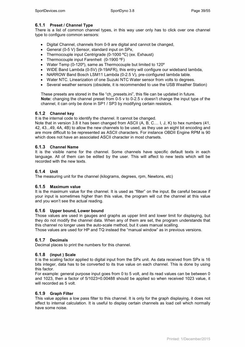
SportDevices.com SportDyno 3.8 Page 39/55
Printed: 1/December/2015
6.1.1 Preset / Channel Type There is a list of common channel types, in this way user only has to click over one channel type to configure common sensors:
• Digital Channel, channels from 0-9 are digital and cannot be changed,
• General (0-5 V) Sensor, standard input on SPx,
• Thermocouple input Centrigrade (0-1000 ºC) (ex. Exhaust)
• Thermocouple input Farenheit (0-1900 ºF)
• Water Temp (0-120º), same as Thermocouple but limited to 120º
• WIDE Band Lambda (0-5V) (9-19AFR), this entry will configure our wideband lambda,
• NARROW Band Bosch LSM11 Lambda (0-2.5 V), pre-configured lambda table.
• Water NTC. Linearization of one Suzuki NTC Water sensor from volts to degrees.
• Several weather sensors (obsolete, it is recommended to use the USB Weather Station) These presets are stored in the file “ch_presets.ini”, this file can be updated in future. Note: changing the channel preset from 0-5 v to 0-2.5 v doesn’t change the input type of the channel, it can only be done in SP1 / SP3 by modifying certain resistors.
6.1.2 Channel key It is the internal code to identify the channel. It cannot be changed. Note that in version 3.8 it has been changed from ASCII (A, B, C.... I, J, K) to hex numbers (41, 42, 43...49, 4A, 4B) to allow the new channels to be used, as they use an eight bit encoding and are more difficult to be represented as ASCII characters. For instance OBDII Engine RPM is 90 which does not have an associated ASCII character in most charsets.
6.1.3 Channel Name It is the visible name for the channel. Some channels have specific default texts in each language. All of them can be edited by the user. This will affect to new tests which will be recorded with the new texts.
6.1.4 Unit The measuring unit for the channel (kilograms, degrees, rpm, Newtons, etc)
6.1.5 Maximum value It is the maximum value for the channel. It is used as “filter” on the input. Be careful because if your input is sometimes higher than this value, the program will cut the channel at this value and you won’t see the actual reading.
6.1.6 Upper bound, Lower bound Those values are used in gauges and graphs as upper limit and lower limit for displaying, but they do not modify the channel data. When any of them are set, the program understands that this channel no longer uses the auto-scale method, but it uses manual scalling. Those values are used for HP and TQ instead the “manual window” as in previous versions.
6.1.7 Decimals Decimal places to print the numbers for this channel.
6.1.8 (input ) Scale It is the scaling factor applied to digital input from the SPx unit. As data received from SPx is 16 bits integer, data has to be converted to its true value on each channel. This is done by using this factor. For example: general purpose input goes from 0 to 5 volt, and its read values can be between 0 and 1023, then a factor of 5/1023=0.00488 should be applied so when received 1023 value, it will recorded as 5 volt.
6.1.9 Graph Filter This value applies a low pass filter to this channel. It is only for the graph displaying, it does not affect to internal calculation. It is useful to display certain channels as load cell which normally have some noise.
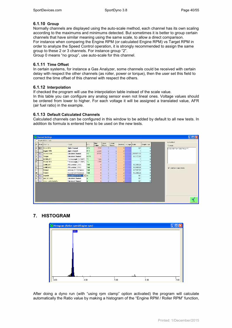
SportDevices.com SportDyno 3.8 Page 40/55
Printed: 1/December/2015
6.1.10 Group Normally channels are displayed using the auto-scale method, each channel has its own scaling according to the maximums and minimums detected. But sometimes it is better to group certain channels that have similar meaning using the same scale, to allow a direct comparison. For instance when comparing the Engine RPM (or calculated Engine RPM) vs Target RPM in order to analyze the Speed Control operation, it is strongly recommended to assign the same group to these 2 or 3 channels. For instance group “2”. Group 0 means “no group”, use auto-scale for this channel.
6.1.11 Time Offset In certain systems, for instance a Gas Analyzer, some channels could be received with certain delay with respect the other channels (as roller, power or torque), then the user set this field to correct the time offset of this channel with respect the others.
6.1.12 Interpolation If checked the program will use the interpolation table instead of the scale value. In this table you can configure any analog sensor even not lineal ones. Voltage values should be ordered from lower to higher. For each voltage it will be assigned a translated value, AFR (air fuel ratio) in the example.
6.1.13 Default Calculated Channels Calculated channels can be configured in this window to be added by default to all new tests. In addition its formula is entered here to be used on the new tests.
7. HISTOGRAM
After doing a dyno run (with “using rpm clamp” option activated) the program will calculate automatically the Ratio value by making a histogram of the “Engine RPM / Roller RPM” function,

SportDevices.com SportDyno 3.8 Page 41/55
Printed: 1/December/2015
to find out the value that is more common during the test (only for the sections where the engine accelerates) If user wants to see the histogram, he can select it on the test menu, or by right-clicking over the desired test. In this window all values from 0 to 7 for ratio are shown. And the amount of number of times this value was present when calculating the ratio function for each test sample. Finally the most repeated ratio value is shown with a label (3.64 in the example).

SportDevices.com SportDyno 3.8 Page 42/55
Printed: 1/December/2015
8. LOAD CELL WIZARD This window eases the Load Cell calibration process. It is divided into two steps:
8.1 Load Cell zeroing
With the load cell free, press the “Set to Zero” button and check the “load cell zero” value is between 30000 and 33000, otherwise there may be some problem on the wiring or on the SPx unit.
8.2 Load Cell Scale
With the load cell mounted on the brake, and the calibration bar attached to the brake, and the calibration weight set at the end of calibration bar, enter the values on the white boxes and press the “Calibrate” button. Check that the load cell reading (blue number, N*m) matches the “torque will read” number. It is recommended that the calibration bar is balanced with a balancing weight on the other side of the brake before placing the calibration weight. A few kilograms will be needed. Finally, press OK button to finish the calibration process.

SportDevices.com SportDyno 3.8 Page 43/55
Printed: 1/December/2015
9. PID Monitor (SP4 / SP5) Sportdyno Ver 3.8 combines PID monitor and PID configuration windows in a single window to ease the PID (speed control) setup process.
9.1 PID Mode
9.1.1 Idle It sets the brake output to 0. It is useful to do inertial tests.
9.1.2 Steady It enters SP4 / SP5 in the steady mode. A RPM Target is set to keep the Engine RPM fixed when Engine tries to overpass this Target point (it does not accelerate the Engine by itself). SP4 and SP5 have a PID Controller that calculates the brake output as a function of Engine RPM input, RPM Target and PID coefficients.
9.1.3 Ramp (Sweep Test) Once the Engine is steady, we can enter in the Ramp Mode, in which the SP4 / SP5 will increase the Target RPM at a fixed rate (Ramp Tate) until the “Max RPM” value is reached. This mode only works when the user is accelerating, for RPM values near or higher than the current Target. If the user closes the throttle, when Engine RPM is lower than Target RPM, the SP4 / SP5 will detect that condition and will adjust the Target for the new speed in order to have a suitable starting RPM Target in case the user decides to accelerate again (although this is not the right way to use this mode). Minimum RPM value that will be allowed for Ramp Mode is defined on the Ramp frame (below) in order to not stall the engine.
9.1.4 Brake When entering this mode, a fixed value is applied to the brake. It is useful for test purposes and to stop the dyno when the test is finished (Pause key on gauges window). Note: If the engine is not running, brake mode will disconnect the brake automatically after a few seconds in order to not overheat the coils.
9.2 Ramp Limits (Sweep) These two values set the starting and ending point for a Ramp Test. Please refer to section 10
9.3 PID Settings

SportDevices.com SportDyno 3.8 Page 44/55
Printed: 1/December/2015
Kp, Ti and Overshoot values are used to control the Engine RPM when the PID is at Steady or
Ramp modes. Please refer to section 10.
9.4 Misc settings Please refer to section 10.
9.5 Recall Button This function will ask the SP4 / SP5 configuration (again). It is useful to test the link with the SP4 / SP5 and to check all values are right.
9.6 Numeric Boxes PID Monitor Window allocates several numeric boxes that can be used to display any channel. To edit the channel displayed just right-click over the box to be edited.
10. SP4 / SP5 Specific Settings This section mainly describes PID settings (speed control), and other settings which are specific for SP4 and SP5. Some of them can be found at both Config Window and PID monitor Window, and others only at Config Window.
10.1 PID Settings
Kp, Ti and Overshoot values are used to control the Engine RPM when the PID is at Steady or Ramp modes.
• Kp: Proportional Gain Control, (the bigger Kp, the faster the control, but it will oscillate on excessive values)
• Ti: Integral Time Constant. For little Ti the faster the drift/approach, but they make the system slower to changes. Values under 0.5 should not be used.
• Td (SP4) / Overshoot (SP5). Overshoot coefficient provides a more advanced method than the classical Td. The higher the value, the stronger the overshoot control, but excessive values create high frequency noise on the brake, and even oscillations.
Please read the SP4 / SP5 Setup documentation.
10.2 Ramp Limits (Sweep) Min RPM and Max RPM values are used in the Ramp Mode as limits to the ramp auto-increment. When the Engine decreases its speed (because throttle is closed) the system detects this condition and decreases automatically the Target RPM, this value is limited by the “Ramp MIN” value. When the Engine is accelerating, the Target value is increased automatically at the ramp rate until the “Ramp MAX” value is reached. If any of these values are set to zero, then it has no effect (PID will not force RPM to zero!)
10.3 Air Speed With certain SP4 units and all SP5 units, the servo2 output can be used to control the output signal to a VFD that powers a 3 phase motor connected to an air turbine.
• Roller RPM min is the speed value to start the operation for the air speed output. For instance if Roller RPM min = 1000 rpm, for all speed values between 0 and 1000 rpm, the output will be zero.
• Roller RPM max is the speed value in which the air speed output reaches 100%. For instance if Roller RPM max = 4000 rpm, for all speed values above 4000 rpm, the output will be 100% (5 volt)
• For all values of roller speed between Roller RPM min and Roller RPM max, the output will be a linear function proportional to the position between these two values.

SportDevices.com SportDyno 3.8 Page 45/55
Printed: 1/December/2015
0%
10%
20%
30%
40%
50%
60%
70%
80%
90%
100%
0 1000 2000 3000 4000 5000
RPM
Ou
tpu
t %
Air Speed Output Function (min=1000, max=4000)
10.4 Misc Settings
10.4.1 Min Roller (SP5).
When Roller speed is below this value, PID output is zero. This allows to prevent engine to stall, or if a centrifugal clutch is used it prevents it to get damaged. Note that the setting is for Roller RPM not Engine RPM
10.4.2 Max Roller (SP5).
This setting fixes a maximum allowed speed for the system. If the system tries to go over this speed the brake will reach 100% its value. This may create oscillations but it is preferable to overpass the safety speed (if any). Note that if it is set to zero, then no max roller speed will be used.
10.4.3 Ratio.
This value is the relationship between Engine RPM and Roller RPM. All RPM values in the SP4 / SP5 are referred to the Engine RPM, but speed is measured on the Roller / Brake, thus Ratio value is very important as it creates the internal Calculated Engine RPM channel which is used for speed control. On the gauges window, when using the RPM Clamp, the Ratio is calculated in real time and sent to SP4 / SP5. Once the test is started the last Ratio value calculated is kept for the whole test.
10.4.4 Number of Teeth (geartooth). For suitable PID operation it is recommended to use a gear tooth of at least 8 teeth.
10.4.5 Prescaler (SP1 to SP4). Depending on the number of teeth, prescaler has to be set among 1, 4 and 16. Usually prescaler=1 is used for number of teeth lower than 16. Prescaler=4 for 16 to 64, and prescaler=16 for higher number of teeth. Note that SP5 always use prescaler = 1.

SportDevices.com SportDyno 3.8 Page 46/55
Printed: 1/December/2015
10.4.6 AWD Mode (SP5). As SP5 has dual Roller Channel set (roller speed, load cell and brake output), it allows 3 modes:
• Only Front. It uses the channels closer to the RS232 connector. This mode is used for all single axle dynos, and for AWD dyno using Front axle.
• Only Rear. It uses the channels closer to the MAINs plug. This mode is only used for AWD dyno using Rear axle.
• AWD. It uses the both channels and enables the AWD synchronization. Note that AWD option is a pay-for option, not all SP5s have this option enabled.
10.5 Brake Configuration
10.5.1 Brake for Emergency Stop (SP5). When Emergency Stop button is pressed (Panic Button), SP5 will go to Brake mode, and will apply this fixed value to the brake.
10.5.2 Brake offset. Some Brake Power Supplies are not full linear (for instance former Semikron PWS). They start to provide current from brake values higher than 130 (13%). Note that this could change depending on the mains frequency on your country. This offset is added to the brake action (when it is higher than 0) to get a suitable control signal over the power supply.
11. Throttle Configuration
11.1 Throttle Setup Here are setup the servo start and ending positions. It is important not to force the servo. Min and max positions can be reversed in order the servo moves in the opposite direction.
• Normal operation: the sliding bar to the left moves the servo.
• Set THR min: sets the minimum position for the servo
• Set THR max: sets the maximum position for the servo. Be careful to not force the servo against the Throttle body max allowed position.
11.2 Throttle Open / Close rate By default, a value of 50 or higher at these values will make the servo open and close quickly, but by setting low values (1, 2, etc) it will move slowly. It is only available for servo 1 (throttle)
11.3 Self-Tune Using this option and one analog channel connected to the servo potentiometer the program will find out the min and max positions for the servo when installed on a certain throttle body (it calibrates the throttle).
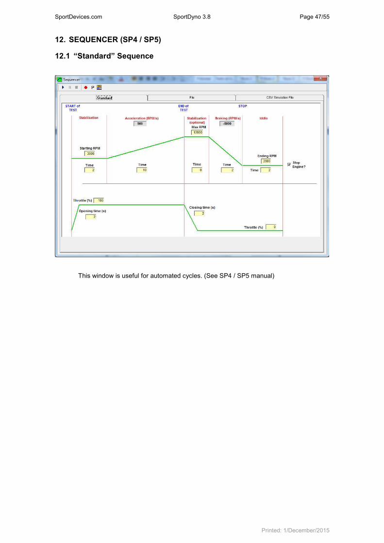
SportDevices.com SportDyno 3.8 Page 47/55
Printed: 1/December/2015
12. SEQUENCER (SP4 / SP5)
12.1 “Standard” Sequence
This window is useful for automated cycles. (See SP4 / SP5 manual)

SportDevices.com SportDyno 3.8 Page 48/55
Printed: 1/December/2015
12.2 File Sequence
Engine Test Cycles can be used to have an engine running several hours to test its reliability, and for pollution tests. The programmed sequence is stored in a text file and automated by the program by using simple orders like THR=10, REF=3000, etc. One level loop is allowed to repeat certain program sequence a known number of times.
Sequencer Commands [updated]
Command Description
RELAY(n) = on | off Turn Relay (n) ON or OFF. 7=IGNITION, 6-STARTER, 2-GEAR-DOWN, 1-GEAR UP, 0=CLUTCH
MODE = I | S | R | B | T I=IDDLE, S=STEADY, R=RAMP, B=BRAKE, T = Inertia Mult
THR = n% Throttle 0..100%
REF = rpm Set TARGET to rpm
RAMP = rpm / s Set RAMP RATE to rpm/s
BRAKE = n Set BRAKE TO n (%)
Test mode Control
AUTO_START = ON | OFF Sets auto Start mode ON or OFF
AUTO_STOP = ON | OFF Sets auto Stop mode ON or OFF
STOP_MODE = L | H | R Sets Stop mode to L = 'Stop when lower', H = 'Stop when higher', R = 'Reversed'
MIN_RPM = n Sets starting value for ramp mode
MAX_RPM = n Sets ending value for ramp mode
RATIO = n.nnn Sets Ratio for current test
Delays and Loops
TIME= n.n Or Delay = n.n
WAITs n.n seconds
WAIT_END_OF_TEST Returns when the recording finishes, for instance 'auto stop'

SportDevices.com SportDyno 3.8 Page 49/55
Printed: 1/December/2015
LOOP n . ENDLOOP
Repeat N times, loops cannot be nested
label: label for GOTO
GOTO n | label Go to line N, or go to LABEL
WAIT_CH n > val Waits Channel N to be HIGHER than val, CH=@ is ESPACE (meters)
WAIT_CH n < val Waits Channel N to be LOWER than val, CH=@ is ESPACE (meters)
RECORD= on | off Start/Stop recording data
12.3 CSV Simulation File Version 3.8 can load a CSV file (Comma Separated Values) and use it for sending speed and throttle data to SP4 / SP5, and perform a simulation of a race track which was recorded with a Data Logger. Mode of operation is simple: just load the file and press “play” sign. File format: It admits two basic CSV formats:
• Values separated by semicolons: 111; 222; 333....
• Values between quotation marks ( “ “ ) and separated with commas: “111”, “222”, “333” First line of the file (header) is ignored. Only the first three columns of the CSV are used:
• First column is always Time (s)
• Second column is always Engine RPM
• Third column is always Throttle position (%)

SportDevices.com SportDyno 3.8 Page 50/55
Printed: 1/December/2015
13. Calculated Channels Calculated Channels can be added to existing tests. They will take the Channel basic data (key and name) from an existing channel from the total channel list (not only SPx device channel list) and will use the specified formula to get data from other channels and perform the calculations that will provide the data for the new channel.
Calculated channels are recalculated every time that anything is changed in the test (ratio, inertia, etc)
13.1 How to use it? When the “Add Calculated Channel” option is selected from the main window the program will show the screen above.
Press the “+” button to automatically find the next free channel. If latest channel used in the test was 4B-Lambda 2, it will choose 4C-Probe 3 (as in the example). The user can also choose a different channel (including existing ones), and the program will show the default data for the channel (if it is new) or the current data for the channel (if it already exists) including the formula if it is an existing calculated channel.
Next step is giving the channel a meaning name, for instance: “calculated power”, and their corresponding units (HP), decimals (1) and formula.
Note: “-“ button has the same effect as “Remove Channel” in Test menu.
13.2 How to use the formula field? Within the formula the user can combine Channels, Constant values (numbers), Constants and operators. Prefixes to refer the items: The formula consists of a series of 4 basic elements:
• Channels
• Program Constants
• Operators
• Test Constants
13.2.1 Channels
• To access to the data of an existing channel (for that test) write Ck (k is the channel’s key), for instance roller channel is C0, engine channel C1, Lambda 1 channel CJ
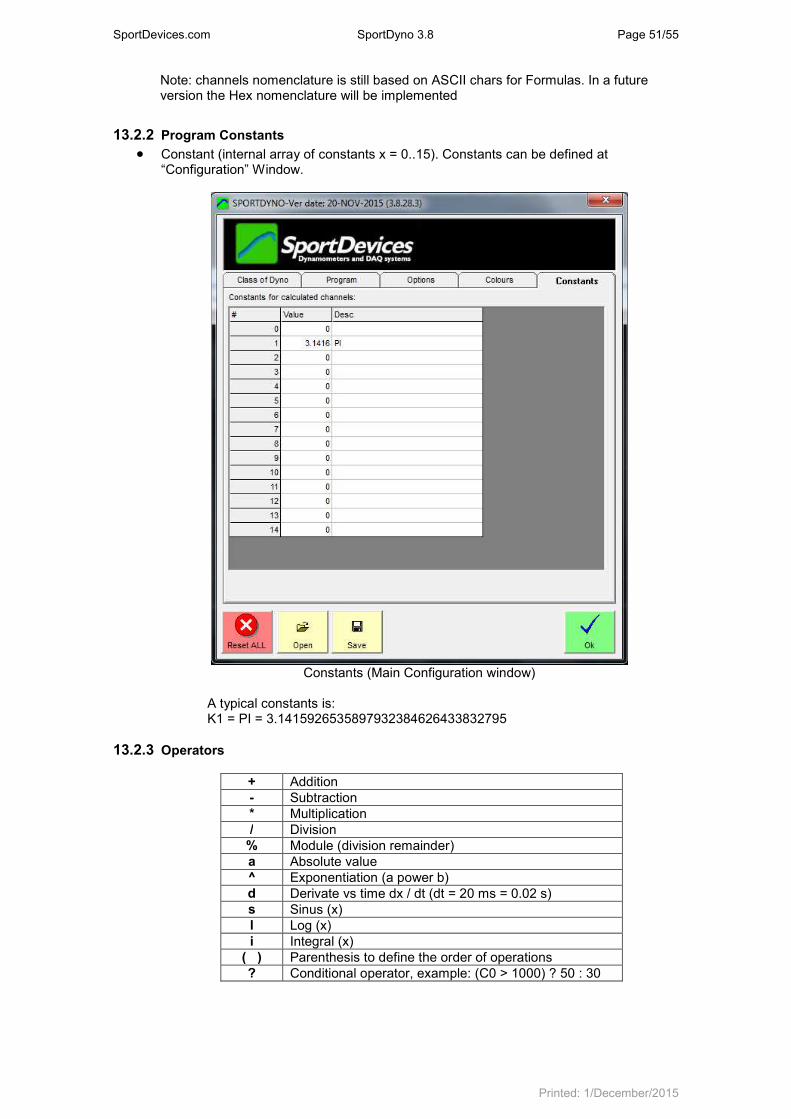
SportDevices.com SportDyno 3.8 Page 51/55
Printed: 1/December/2015
Note: channels nomenclature is still based on ASCII chars for Formulas. In a future version the Hex nomenclature will be implemented
13.2.2 Program Constants
• Constant (internal array of constants x = 0..15). Constants can be defined at “Configuration” Window.
Constants (Main Configuration window)
A typical constants is: K1 = PI = 3.1415926535897932384626433832795
13.2.3 Operators
+ Addition
- Subtraction
* Multiplication
/ Division
% Module (division remainder)
a Absolute value
^ Exponentiation (a power b)
d Derivate vs time dx / dt (dt = 20 ms = 0.02 s)
s Sinus (x)
l Log (x)
i Integral (x)
( ) Parenthesis to define the order of operations
? Conditional operator, example: (C0 > 1000) ? 50 : 30

SportDevices.com SportDyno 3.8 Page 52/55
Printed: 1/December/2015
13.2.4 Test constants
I Inertia of current test
t (dt) Time lapse between samples (20 ms)
D Roller diameter of test being calculated
R Ratio of current test
T Total test time
W Vehicle Weight
F Temperature Correction Factor
13.3 Formula examples
Torque (N*m):
d ( C0 / 60 * K0 * 2) * I * 50 + CI
Torque calculated from roller and load cell:
d ( “Roller rpm” / 60 * K0 * 2) * Inertia ------------------------------------------------ + “Load Cell“ dt
or
acceleration (Rad/s) * “Inertia” (kg/m
2) + ”Load Cell”
(N*m)
Power (Watt)
(d ( C0 / 60 * K0 * 2) * I * 50 + CI) * C0 / 60 * K0 * 2
Is equivalent
C3 * C0 / 60 * K0 * 2
Note: to convert to HP divide by 736
Torque (N * m) * Speed (Rad / s)
or
Torque channel (N * m) * Speed (Rad / s)
Speed (m/s)
C0 / 60 * K0 * 2 * D / 1000 / 2
=
C0 / 60 * K0 * D / 1000
(Roller / 60 * PI * 2) * (Diameter / 1000 / 2)
or
“Roller speed” (rad/s) * Diameter (m) / 2
Distance (m):
i ( C0 / 60 * K0 * 2 * D / 1000 / 2) * t
=
i ( C0 / 60 * K0 * D / 1000) * t
Integral of (Roller / 60 * PI) * (Diameter / 1000) * dt
or
Integral of “Roller speed” (rad/s) * Diameter (m) * dt
Or
Integral Speed (m/s) * dt
K0 = 3.1415 (PI)
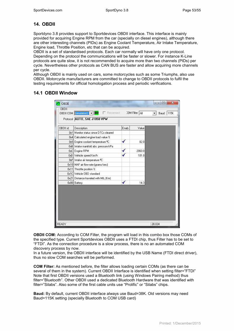
SportDevices.com SportDyno 3.8 Page 53/55
Printed: 1/December/2015
14. OBDII Sportdyno 3.8 provides support to Sportdevices OBDII interface. This interface is mainly provided for acquiring Engine RPM from the car (specially on diesel engines), although there are other interesting channels (PIDs) as Engine Coolant Temperature, Air Intake Temperature, Engine load, Throttle Position, etc that can be acquired. OBDII is a set of standardised protocols. Each car normally will have only one protocol. Depending on the protocol the communications will be faster or slower. For instance K-Line protocols are quite slow, it is not recommended to acquire more than two channels (PIDs) per cycle. Nevertheless other protocols as CAN BUS are faster and allow acquiring more channels per cycle. Although OBDII is mainly used on cars, some motorcycles such as some Triumphs, also use OBDII. Motorcycle manufacturers are committed to change to OBDII protocols to fulfil the testing requirements for official homologation process and periodic verifications.
14.1 OBDII Window
OBDII COM: According to COM Filter, the program will load in this combo box those COMs of the specified type. Current Sportdevices OBDII uses a FTDI chip, thus Filter has to be set to “FTDI”. As the connection procedure is a slow process, there is no an automated COM discovery process by now. In a future version, the OBDII interface will be identified by the USB Name (FTDI direct driver), thus no slow COM searches will be performed. COM Filter: As mentioned before, the filter allows loading certain COMs (as there can be several of them in the system). Current OBDII Interface is identified when setting filter=”FTDI” Note that first OBDII versions used a Bluetooth link (using Windows Pairing method) thus filter=”Bluetooth”. Other OBDII used a dedicated Bluetooth Hardware that was identified with filter=”Silabs”. Also some of the first cable units use “Prolific” or “Silabs” chips. Baud: By default, current OBDII interface always use Baud=38K. Old versions may need Baud=115K setting (specially Bluetooth to COM USB card)

SportDevices.com SportDyno 3.8 Page 54/55
Printed: 1/December/2015
Status and Protocol: During the OBDII connection establishment, the driver will show the status of the connection (searching PIDs 00.. etc). After connection is complete, it will show the protocol name and details for that car. Normally each car has only one protocol, but there are cars with combinations of slow protocols and CAN. PID list: Channel identifiers are called PIDs in the OBDII nomenclature. Once the OBDII device has been identified, and the connection has been established with the car, the program will show the list of available PIDs. Each car has only some PIDs. Manufacturers are not obliged to implement all PIDs. Nevertheless most car have a fixed subset including: Engine RPM, Engine coolant Temp, Intake Air Temp, etc Once the PIDs are listed, user must choose only a few PIDs (enable column) to be acquired, as OBDII is not very fast in general, and acquisition cycle should not be more than 500 ms (approx). On slow protocols as K-line, even only two PIDs can reach the 500 ms limit, but with CAN BUS time is about 100 ms for 3 PIDs. These channels will be automatically acquired on both Gauges Window, and Test Recording.
14.2 OBDII Authentication As OBDII is a pay-for feature in Sportdyno, an authentication mechanism has been provided. Some of the first OBDII units have special info recorded on them, and thus they do not need the manual authentication. And also a future version could use the USB serial numbers to identify the unit. But by now, most units require manual authentication. User has to send us an email with the Network info that the “Copy” button provides. Then an authentication key is sent to the user, and the user enters it on the software, and press “Check” button. This key can only be used in one computer

SportDevices.com SportDyno 3.8 Page 55/55
Printed: 1/December/2015
15. Appendix I. What is new in this version? (Main topics)
• SP5 Support
• OBDII Support (also integrated on Ratio calculation)
• Configuration Management: o PID configuration rearranged on PID monitor window o Throttle Configuration o Configuration supervision algorithm o Reviewed config loading and saving o Gauges Window also allows to load and save its layout
• Improved low pass filter for braked dynos
• Provision for other external data sources: OMEGA IR sensor, Exhaust Gas Analyzer, Power Supply telemetry (3.1)