split flow & full condenser and vortex granulation ... · the urea plant after urea casale...
TRANSCRIPT
- 167 -
Split Flow & Full Condenser and Vortex Granulation Technologies
Application in China: A remarkable and proven Way to surprisingly enhance Urea Plant
Capacity STEFANO REGGIORI
Urea Casale S.A. Lugano, Switzerland
CASALE Group is the worldwide leader technology company in the field of revamping and modernization of Ammonia, Methanol and Urea plants.
This paper provides details about the first application in China of two technologies developed by CASALE for the up gradation of existing Urea plants. In particular the Split Flow and Full Condenser Technology is the most advanced and proven way to boost CO2 stripping plants for the last ten years and the Vortex Granulation Technology is the recent way that CASALE developed to increase the capacity of prilling urea plants providing also for a significant increase of product quality.
Project overview as well as process performances are discussed.
1. PROJECT BACKGROUND A major Chinese Group leader in the fertilizer market is the Owner of the Ammonia-Urea complex object of the CASALE revamping project. First site construction activities began in 1980 and production started in 1983. Afterwards in the 2000s the plants were relocated in another Chinese area, based on the natural gas availability. The plants were moved without introducing any modification to the original design.
S. Reggiori
168 Nitrogen + Syngas 2014 International Conference & Exhibition (Paris 24-27 Februaryr 2014)
The existing facility comprises of 1000 MTPD, Kellog designed Ammonia plant and a 1500 MTPD Stamicarbon designed urea plant. The plants have fully integrated utility units with storage facilities. Presently, Urea plant is operating at 116% of its original name plate capacity (1740 MTPD). The company has been continuously improving its technology and productivity based on worldwide Urea market trend. The Client engaged CASALE Group in 2009-2010 to conduct a Technical Study to enhance the entire complex (Ammonia and Urea plants) capacity in order to reach 2610 MTPD of solid urea daily production. Ammonia CASALE (ACSA) Technical Study formed the basis of the Ammonia Plant Internals Revamping Project. The developed Ammonia Plant Internals Revamping Project by CASALE formed the basis of a Process Design Package composed of three main Ammonia CASALE patent Components:
• new 4th reactor bed cartridge;
• HTS new internals;
• secondary reformer burner. Urea CASALE (UCSA) Technical Studies formed the basis of the Urea Plant Revamping and Vortex Granulation Unit Projects. The developed Projects by CASALE formed the basis of an integrated Process Design Package composed of two main overall Components:
• Modifications to the Urea Plant (whole plant) to enhance its capacity from 1740 to 2610 MTPD enabling it to transform the extra amount of ammonia produced in the revamped ammonia plant into urea.
• Installation of a new 2610 MTPD Fattening unit using CASALE Vortex Granulation license. The Urea plant after Urea CASALE Process Design Package implementation will produce 2610 MTPD. This paper describes the modifications in the CO2 stripping Urea Plant originally designed with a name plate capacity of 1500 MTPD, operated at 1740 MTPD and revamped for a target capacity of 2610 MTPD utilizing Urea CASALE’s proprietary technologies of CASALE-Dente High Efficiency Trays, Split Flow loop and Full Condenser, MP Split Flow Section and Vortex Granulator.
2. PROJECT OBJECTIVES AND CASALE SCOPE OF WORK In addition to the 50% increase in capacity (74% increase compared to original nameplate capacity), then the following revamping targets are defined:
• to find out the most efficient configuration to fulfil the capacity increase and, at the same time, to minimize investment cost;
• to increase of the CO2 conversion in the urea reactor;
• to minimize the overall specific energy and utilities consumption of the plant;
• to increase the final product quality;
• to minimize the installation of additional High Pressure equipment;
• to minimize the number of equipment to be modified and to be added, reusing as much as possible the existing items;
• to guarantee the highest operation flexibility ensuring, at the meantime, reliable and stable operation.
All the objectives are achieved thanks to CASALE knowledge and proprietary technologies application. The Contracts has covered the provision of the following services:
• License of technologies
• Process Design Package for whole Urea Plant and Vortex Granulation Unit
Split Flow & Full Condenser and Vortex Granulation Technologies Application in China: A remarkable and proven Way to surprisingly enhance Urea Plant Capacity
Nitrogen + Syngas 2014 International Conference & Exhibition (Paris 24-27 February 2014) 169
• Assistance and check of the Detail Engineering
• Supply of proprietary equipment
• Site Assistance during construction
• Site Supervision during commissioning, start-up and test-run Detail Engineering activities have been done by Chinese Design Institutes under assistance of Urea CASALE; equipment purchasing has been done by Owner with Design Institutes assistance; construction has been done by local companies under assistance and supervision of Urea CASALE staff.
3. UREA CASALE REVAMPING CONCEPT AND SPECIFIC TECHNOLOGIES The modifications implemented in the Urea Plant to comply with the increased capacity and project objectives are described as follows:
• Implementation of Urea CASALE technologies, namely the Full Condenser and Split Flow Loop [1], in order to upgrade CO2 stripping Urea Plant solution Section from 1740 up to 2610 MTPD.
• Urea reactor performance improvement by adopting the CASALE-Dente high efficiency trays [1] which are the most efficient trays available in the market and are also an essential element to make Split Flow Loop as efficient as possible.
• HP Synthesis loop debottleneck through implementation of a Decomposition and Condensation Section operating in parallel to the existing HP Stripper (MP Split Flow Section [1]). The urea solution from the Reactor is split in two parts, one part to existing Stripper and other part to the new Decomposer. By condensing ammonia and CO2 at medium pressure it is possible to recycle to Synthesis Section a carbamate solution more concentrated, increasing the performance of the Reactor, with respect to the recovery of un-reactants at low pressure.
• The last important element to complete the process scheme is the CASALE Vortex Granulator [2] technology for debottlenecking the solid section of the plant. The solid prills from the existing prilling tower and the additional urea melt are sent to the fattening unit. High quality final product is obtained.
4. REVAMPING DESCRIPTION This paragraph details the modifications implemented and CASALE technologies applied to upgrade Urea Plant capacity and performances.
S. Reggiori
170 Nitrogen + Syngas 2014 International Conference & Exhibition (Paris 24-27 Februaryr 2014)
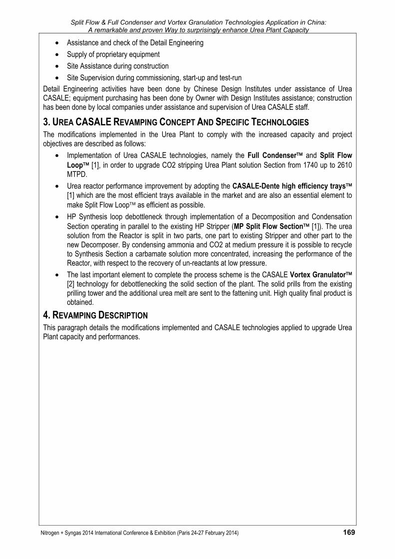
Fig. 1: Plant Revamping Scheme
4.1. HP Section HP Synthesis Loop capacity and performances have been maximized applying CASALE patented technologies, thus minimizing the new HP equipment required. The three main equipment of the loop (i.e. Reactor, Stripper and Carbamate Condenser) has been reused and just minor modifications have been included to fit the CASALE internals. In particular, the existing Reactor has been modified by replacing the existing trays with a set of new CASALE-Dente High Efficiency Trays. Existing HP Stripper has been modified to fit the equipment for the new load and to provide the new Split Flow Loop configuration. Existing HP Carbamate Condenser has adapted to CASALE Full Condenser technology to enhance equipment performance and to fit the equipment to provide the new Split Flow configuration. Existing HP Scrubber was replaced since the existing one was at the end of its working life. The new HP Scrubber has been designed for the new plant capacity and to match the required target of energy saving, allowing heat recovery from the Tempered Cooling Water (TCW) loop. Heat recovery from the HP Scrubber is implemented installing a new 1st Stage Vacuum Evaporator upstream the existing one, thus minimizing the steam consumption in the latter one. The heat recovery implementation allows to obtain a significant 3.5 barg steam and CW saving. Additional pumping capacity has been added as well for circulation of TCW loop. After revamping, according to Owner request, to cover the new demand of fresh ammonia and to have high plant reliability, a new HP Ammonia centrifugal pump (motor driven) for full capacity has been added. Both the existing reciprocating pumps (turbine driven) have been kept as spare and run in parallel when required. Due to the increase in requirement of CO2 flow, according to Owner request, the old CO2 Compressor, centrifugal type, has been replaced by a new one. In order to increase plant safety a catalytic Hydrogen Converter has been added to remove the hydrogen contained in the CO2 feedstock.
Split Flow & Full Condenser and Vortex Granulation Technologies Application in China: A remarkable and proven Way to surprisingly enhance Urea Plant Capacity
Nitrogen + Syngas 2014 International Conference & Exhibition (Paris 24-27 February 2014) 171
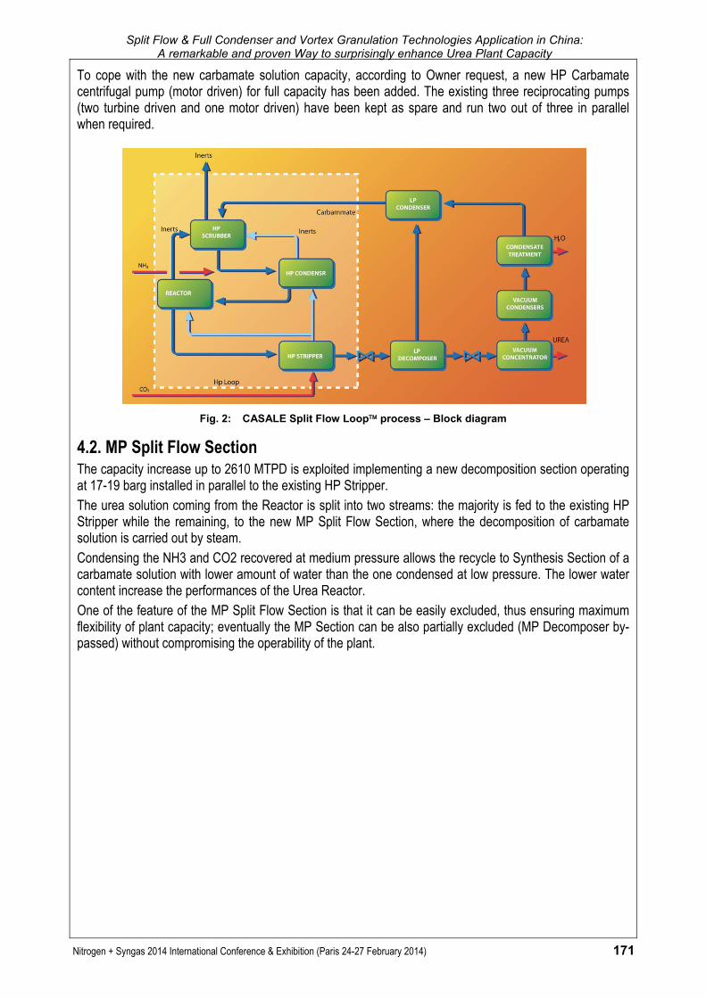
To cope with the new carbamate solution capacity, according to Owner request, a new HP Carbamate centrifugal pump (motor driven) for full capacity has been added. The existing three reciprocating pumps (two turbine driven and one motor driven) have been kept as spare and run two out of three in parallel when required.
Fig. 2: CASALE Split Flow Loop process – Block diagram
4.2. MP Split Flow Section The capacity increase up to 2610 MTPD is exploited implementing a new decomposition section operating at 17-19 barg installed in parallel to the existing HP Stripper. The urea solution coming from the Reactor is split into two streams: the majority is fed to the existing HP Stripper while the remaining, to the new MP Split Flow Section, where the decomposition of carbamate solution is carried out by steam. Condensing the NH3 and CO2 recovered at medium pressure allows the recycle to Synthesis Section of a carbamate solution with lower amount of water than the one condensed at low pressure. The lower water content increase the performances of the Urea Reactor. One of the feature of the MP Split Flow Section is that it can be easily excluded, thus ensuring maximum flexibility of plant capacity; eventually the MP Section can be also partially excluded (MP Decomposer by-passed) without compromising the operability of the plant.
S. Reggiori
172 Nitrogen + Syngas 2014 International Conference & Exhibition (Paris 24-27 Februaryr 2014)
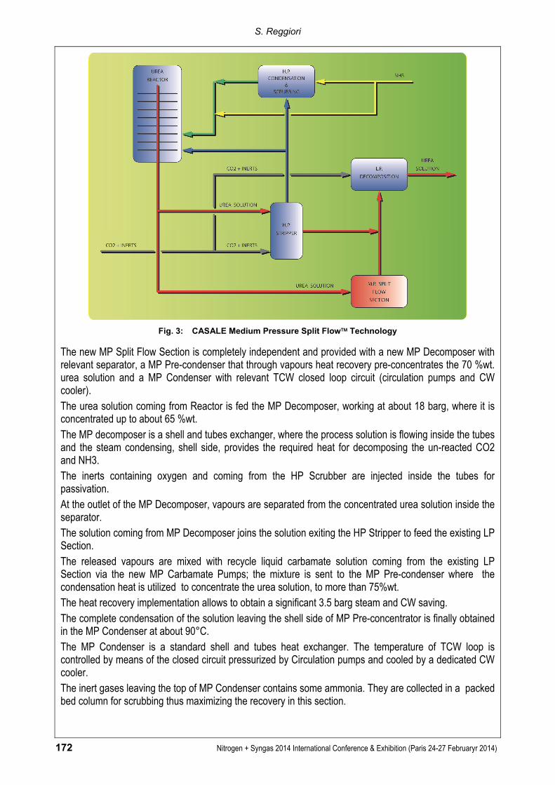
Fig. 3: CASALE Medium Pressure Split Flow Technology
The new MP Split Flow Section is completely independent and provided with a new MP Decomposer with relevant separator, a MP Pre-condenser that through vapours heat recovery pre-concentrates the 70 %wt. urea solution and a MP Condenser with relevant TCW closed loop circuit (circulation pumps and CW cooler). The urea solution coming from Reactor is fed the MP Decomposer, working at about 18 barg, where it is concentrated up to about 65 %wt. The MP decomposer is a shell and tubes exchanger, where the process solution is flowing inside the tubes and the steam condensing, shell side, provides the required heat for decomposing the un-reacted CO2 and NH3. The inerts containing oxygen and coming from the HP Scrubber are injected inside the tubes for passivation. At the outlet of the MP Decomposer, vapours are separated from the concentrated urea solution inside the separator. The solution coming from MP Decomposer joins the solution exiting the HP Stripper to feed the existing LP Section. The released vapours are mixed with recycle liquid carbamate solution coming from the existing LP Section via the new MP Carbamate Pumps; the mixture is sent to the MP Pre-condenser where the condensation heat is utilized to concentrate the urea solution, to more than 75%wt. The heat recovery implementation allows to obtain a significant 3.5 barg steam and CW saving. The complete condensation of the solution leaving the shell side of MP Pre-concentrator is finally obtained in the MP Condenser at about 90°C. The MP Condenser is a standard shell and tubes heat exchanger. The temperature of TCW loop is controlled by means of the closed circuit pressurized by Circulation pumps and cooled by a dedicated CW cooler. The inert gases leaving the top of MP Condenser contains some ammonia. They are collected in a packed bed column for scrubbing thus maximizing the recovery in this section.

Split Flow & Full Condenser and Vortex Granulation Technologies Application in China: A remarkable and proven Way to surprisingly enhance Urea Plant Capacity
Nitrogen + Syngas 2014 International Conference & Exhibition (Paris 24-27 February 2014) 173
The condensed carbamate liquid solution is pumped back to the HP Synthesis Loop either by the new HP Carbamate centrifugal Pump or by the three existing HP reciprocating Pumps (upgraded for the higher suction pressure). The scrubbed inerts are sent to MP Absorber column for final washing.
Fig. 4: CASALE Medium Pressure Split Flow Section
4.3. LP Section LP Decomposition and Recycle Section capacity has been enhanced according to the new design plant load. Debottleneck interventions, additional surfaces and pumping capacity were required. Urea solution, both from the HP Stripper and the MP Decomposer, are fed into the new LP Separator vessel where the gas/liquid separation is achieved. Therefore only the liquid phase is sent to the existing rectifying column, where the liquid distribution is improved by new CASALE design internals of more efficient concept. The liquid from new LP Separator enters top of Rectifying Column which in turn enters into Recirculation Heater for further decomposition. Surface increasing was obtained installing a small additional exchanger upstream the existing one. The vapours from the top of Rectifying Column, together with the vapours from new LP Separator join a stream of CO2 from the compressor that is being added in order to guarantee optimum condensation into the LP Condenser (especially when the MP Split Flow Section is in line). The existing LP Condenser, too small for operating at new plant load, has been replaced by a new one provided with increased surface. The circulation pumps as well have been designed with a higher flow rate. The circulation water cooler, according to Owner request, has been replaced since the existing one was at the end of its working life. Both the old LP Condenser and the Circulation pumps were in any case reutilized in other plant’s section. The LP Scrubber (installed above Carbamate Separator for LP Condenser) ammonia water solution circulation scheme has been modified; very small few interventions (internals modification, new piping connection and instruments) allowed to debottleneck the column and, at the same time, to increase the performances.
S. Reggiori
174 Nitrogen + Syngas 2014 International Conference & Exhibition (Paris 24-27 Februaryr 2014)
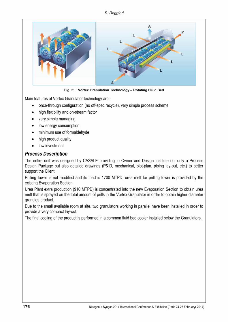
4.4. Vacuum Pre-concentration and Condensation Section The section performances have been increased not only in terms of load, but also implementing the MP vapours heat recovery. The urea solution coming from the Rectifying Column is fed to the MP Pre-condenser where the condensing heat of MP vapours (from MP Decomposer) allows the concentration of urea solution to more than 75 %wt. (refer also to para. 4.2.). The new MP Pre-condenser has been designed to match the required target of energy saving, allowing heat recovery from the released MP Decomposer vapours. The new Flash Separator, coupled with the mentioned exchanger, has been designed for the increased load of vapours. Additional condensing capacity has been provided in this section for the higher vapour load.
4.5. Vacuum Evaporation and Condensation Sections The design capacity of the old Evaporation Section remained unchanged (1700 MTPD about), whereas the extra production (910 MTD about) is handled by a completely independent new Evaporation, Vacuum and Condensation Section, which is installed upon a new structure, close to Vortex Granulation Unit. The aim of the interventions implemented in the old Evaporation Section is to enhance the performance of the unit. More in detail, inside the 1st and 2nd Vacuum Separators special internals, designed by CASALE, are installed to decrease urea carry-over in the outlet gas thus reducing urea content into the process condensate fed to Condensate Treatment Section. Additionally, in order to implement the HP Scrubber TCW loop heat recovery (refer also to para. 4.1.), the 1st Vacuum Evaporator has been replaced completely (due to corrosion problem) by a new one; it consists of two exchangers in series (tubes side). The lower part is heated by means of hot TCW coming from the HP Scrubber cooling loop, where a part of the heat is recovered for concentrating the urea solution. The upper part is heated by means of 3.5 barg steam. The final concentration up to 99.7 %wt. is reached in the 2nd Vacuum Evaporator by means of 8.0 barg steam. Urea Melt is sent to prilling tower as per existing configuration. Vapours are condensed into the existing Vacuum Condensers; diluted process condensate is used for atmospheric vent washing before to be collected with concentrated process condensate and sent to Condensate Treatment Section. The additional urea solution coming from the Urea Solution Tank (by the new dedicated Urea Solution pump for new evaporation) is processed in a dedicated new Evaporation Section, having a capacity of about 910 MTPD. The urea solution from the Urea Solution Tank is sent, together with the recycle from the fattening unit, to the new 1st Evaporator and then to the new 2nd Evaporator where the urea concentration of 99.7 %wt. is reached. The solution from the new 2nd Evaporator is fed via the new Urea Melt Pump to the Vortex Granulator, where the solution is sprayed on the prills used as seeds for obtaining the final product. A dedicated vacuum condensation system is coupled with the new evaporation; the process condensate is collected in the Vacuum Condensate Receiver and hence sent to the Ammonia Water Tank by means of the new Process Condensate Pumps.
4.6. Absorption Section (Inerts Washing) In order to cope with the new plant load (and with the increased inerts to be treated) and to minimize the ammonia emissions to atmosphere, some modifications were implemented.

Split Flow & Full Condenser and Vortex Granulation Technologies Application in China: A remarkable and proven Way to surprisingly enhance Urea Plant Capacity
Nitrogen + Syngas 2014 International Conference & Exhibition (Paris 24-27 February 2014) 175
A new MP Absorber provided with wider absorption surface was necessary because of the increased amount of inerts flow. Improvement in the ammonia absorption are achieved sending clean condensate in the upper part. An additional MP Absorber Circulation cooler was installed in series with the existing; new Circulation pumps, having increased head and capacity, were installed to provide adequate cooling and flow rate to the new MP Absorber. The existing Atmospheric Absorber was replaced by a decommissioned equipment properly modified in order to have enough absorption surface to handle the load at the increased rate.
4.7. Condensate Treatment Section (Waste Water Treatment) Section capacity has been enhanced according to the new design plant load and to obtain high purity treated condensate. Debottleneck interventions, additional surfaces and pumping capacity were required. The function of the revamped Waste Water Treatment Section is to deeply treat the process water produced in the urea plant (recycle water plus formation water) in order to obtain water containing 1 ppm of Urea and NH3 (suitable to be used as BFW) before it is discharged from the urea plant. A new Distillation Column, is being introduced in order to achieve the process condensate quality to be suitable for BFW utilization. This column is divided in two parts thanks to a chimney tray that split the column in the desorption section (upper part) and stripping section (lower part). Upper part removes most part of NH3 and CO2 by means of vapors coming from the lower part through the chimney tray. Stripping medium is 3.5 barg steam. The water from the chimney tray of this column feeds the existing Hydrolyser, thus reducing the urea content in the treated water down to 1 ppm. The capacities of the Reflux Condenser and relevant TCW circuit were increased to cope with higher load. Pumps of the section were replaced by new ones designed according to the increased capacity.
4.8. Finishing Section (Fattening Unit): Vortex Granulator The purpose of the Granulation Unit is the production of urea granules starting from urea prills as seed and urea melt at 99.7 %wt. as coating medium. This operation is performed into a granulator designed according to the CASALE technology of Vortex Granulator. In this item the particle size enlargement is achieved by accretion spraying melt urea on the seeds where it solidifies. The spraying occurs on the extremity of a special internal device named “flap” located inside the granulator laterally, by means of a large number of spray heads. In order to spray onto a large number of solid particles simultaneously with no agglomeration, it is necessary to keep them spaced out. Fluidization is the only method to avoid contact between particles over a long period of time. The shape of granulator and the fluidization air distribution have been studied just to give to the fluid bed both a rotational and forward motion. In this way all the particles of the bed have the same probability to receive the same quantity of sprayed urea melt, and the residence time is the same for all the particles. This assures to have a homogeneous final product.
S. Reggiori
176 Nitrogen + Syngas 2014 International Conference & Exhibition (Paris 24-27 Februaryr 2014)
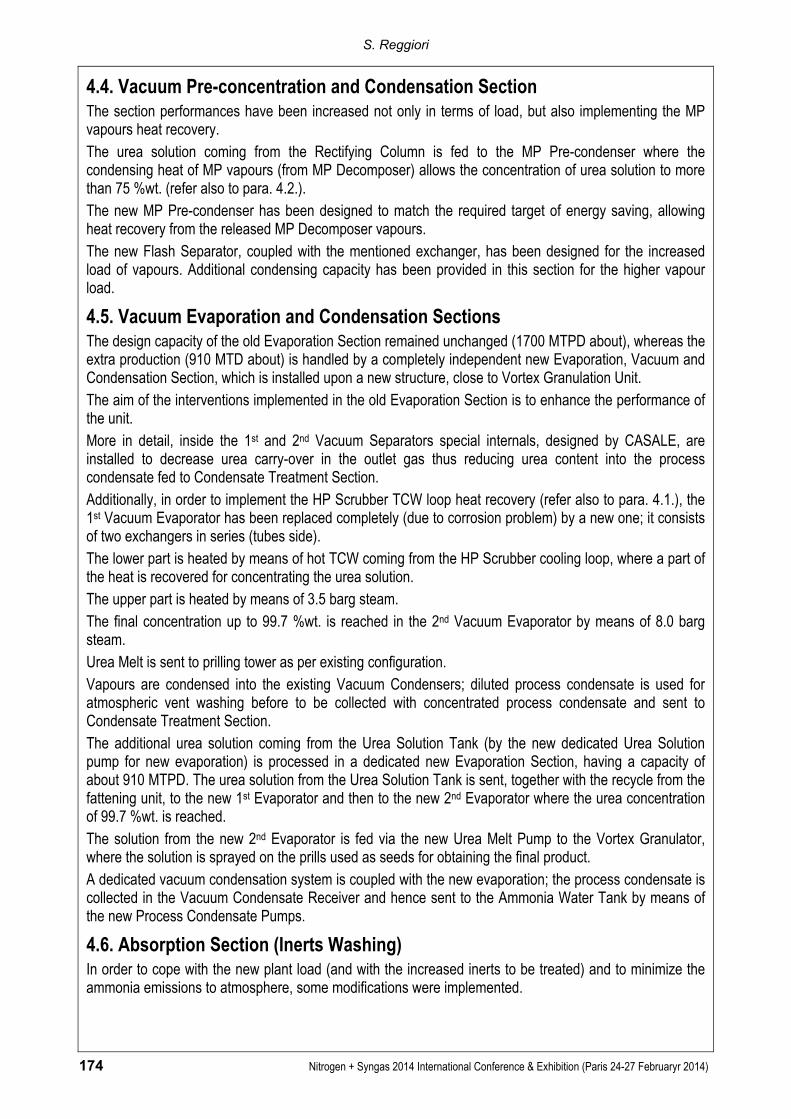
Fig. 5: Vortex Granulation Technology – Rotating Fluid Bed
Main features of Vortex Granulator technology are:
• once-through configuration (no off-spec recycle), very simple process scheme
• high flexibility and on-stream factor
• very simple managing
• low energy consumption
• minimum use of formaldehyde
• high product quality
• low investment
Process Description The entire unit was designed by CASALE providing to Owner and Design Institute not only a Process Design Package but also detailed drawings (P&ID, mechanical, plot-plan, piping lay-out, etc.) to better support the Client. Prilling tower is not modified and its load is 1700 MTPD; urea melt for prilling tower is provided by the existing Evaporation Section. Urea Plant extra production (910 MTPD) is concentrated into the new Evaporation Section to obtain urea melt that is sprayed on the total amount of prills in the Vortex Granulator in order to obtain higher diameter granules product. Due to the small available room at site, two granulators working in parallel have been installed in order to provide a very compact lay-out. The final cooling of the product is performed in a common fluid bed cooler installed below the Granulators.

Split Flow & Full Condenser and Vortex Granulation Technologies Application in China: A remarkable and proven Way to surprisingly enhance Urea Plant Capacity
Nitrogen + Syngas 2014 International Conference & Exhibition (Paris 24-27 February 2014) 177
Fig. 6: Vortex Granulation Unit Scheme
The prilled urea, used as seeds, is collected from the prilling tower, into Urea Prills Tank that feeds both the two Granulators working in parallel. The solid fed from Urea prills tank to Granulator is controlled by a Granulator Feeder. The melt urea from new evaporation section is fed in control of pressure to the urea sprayers general header, and from here it goes to each sprayer where, jointly with emulsion air, is sprayed into the granulator. Emulsion air from atmosphere is compressed by the common compressor and heated into Emulsion Air Heater exchanger upstream the air sprayers general header, and from here enters to each sprayer where, jointly with melt urea, it is sprayed into the granulator. The single sprayer is equipped with a head provided with a calibrated hole from where the emulsioned melt urea is sprayed into the granulator. Inside the head the pressure is determined by the amount of air and urea melt fed and the size of calibrated hole. The optimum performances of the sprayers are guaranteed by the correct pressure difference between the general header of the emulsion air and the general header of urea melt. The addition of, so called, flaps air provides for the heating of the spraying zone as well as the prevention of solid urea deposits around the sprayers. Atmospheric air is delivered by the common Flaps Air Fan and heated up to about 140 °C in Flap Air Heater, then it is divided into two streams one for each granulator. The quantity of air sent to each group of sprayers is regulated by means of louvers. The fluidization of the bed is performed by a common fan. Atmospheric air, filtered and preheated, during winter time, is delivered by means of Granulator Fluidization Air Fan to the granulators. This air exploits three duties. The first part, through Granulator Fluidization Air Heater, is sent to the granulator’s “spraying” section and, distributed by a perforated plate, allows the fluidization of the solid lying on the perforated plate. The Vortex temperature control is performed with the fluidization air temperature that may be preheated at the requested value in the Granulator Fluidization Air Heater (by 3.5 barg steam). Temperature control
S. Reggiori
178 Nitrogen + Syngas 2014 International Conference & Exhibition (Paris 24-27 Februaryr 2014)
may be required according to the ambient air conditions, prills temperature, ratio between melt and solid and, of course, plant load. The second duty relates to the cooling of the bed. Air enters to granulator’s “cooling” section where the fluidized granules are cooled by air. The third part is fed to the final section of granulator, a sort of quiet room where the granules lie down slowly, before discharging them with Granulator Extractor to Safety Screen and then to the common Fluid Bed Cooler, where also the product from parallel line is fed. All the air introduced into the granulator and the entrained air, as the top of granulator is slightly under vacuum, are sent to common Granulator Scrubber to eliminate the dust that is generated inside the granulators. The dust is captured inside the scrubber by means of a urea solution at about 45 %wt. that is sprayed by the Granulator Scrubber Circulation Pump. The washed air, free of dust, by the Granulation Scrubber Exhaust Fan is sent to the Vent Stack and then vented to the atmosphere. The urea solution at 45 %wt., obtained in the Granulator Scrubber, dissolving the urea dust with condensate, is sent to the new Evaporation Section to be recovered though the Drain Tank and related dedicated pumps. Thanks to the special design of the Vortex bed and of the spray nozzles the amount of generated dust is very limited compared to market technologies. In fact the quantity of urea recycled back to Urea solution Plant is only 20 kg of dust per ton of sprayed urea. The urea granules discharged from granulators are cooled in the Fluid Bed Cooler below 55°C (summer period). The fluidization air is supplied by the Cooler Fluidization Air Fan. Air is fed under a grid supporting the granules just to create a fluidized bed. The air crossing the granules bed removes the heat from the urea and is discharged from upper part and sent to the Cooler Scrubber, where the urea dust entrained is washed spraying urea solution recycled with the Cooler Scrubber Circulation Pump. The washed air, free of dust, by the Cooler Scrubber Exhaust Fan is sent to the Vent Stack and then vented to the atmosphere. Condensate coming from Treated Condensate Section is used as make up both to form the urea solution in dissolving urea dust and to saturate the hot air coming from Fluid Bed Cooler and from Granulators. The urea solution generated in the Cooler Scrubber Exhaust Fan is sent to Granulator Scrubber as washing medium. The solid urea from the Fluid Bed Cooler is sent to the belt conveyors and transferred to the storage.
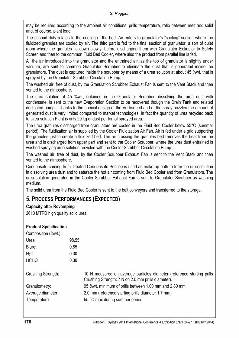
5. PROCESS PERFORMANCES (EXPECTED) Capacity after Revamping 2610 MTPD high quality solid urea. Product Specification Composition (%wt.): Urea 98.55 Biuret 0.85 H2O 0.30 HCHO 0.30
Crushing Strength: 10 N measured on average particles diameter (reference starting prills
Crushing Strength: 7 N on 2.0 mm prills diameter). Granulometry: 95 %wt. minimum of prills between 1.00 mm and 2.80 mm Average diameter: 2.0 mm (reference starting prills diameter 1.7 mm) Temperature: 55 °C max during summer period
Split Flow & Full Condenser and Vortex Granulation Technologies Application in China: A remarkable and proven Way to surprisingly enhance Urea Plant Capacity
Nitrogen + Syngas 2014 International Conference & Exhibition (Paris 24-27 February 2014) 179
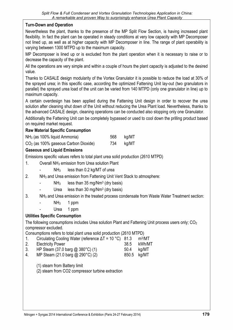
Turn-Down and Operation Nevertheless the plant, thanks to the presence of the MP Split Flow Section, is having increased plant flexibility. In fact the plant can be operated in steady conditions at very low capacity with MP Decomposer not lined up, as well as at higher capacity with MP Decomposer in line. The range of plant operability is varying between 1300 MTPD up to the maximum capacity. MP Decomposer is lined up or is excluded from the plant operation when it is necessary to raise or to decrease the capacity of the plant. All the operations are very simple and within a couple of hours the plant capacity is adjusted to the desired value. Thanks to CASALE design modularity of the Vortex Granulator it is possible to reduce the load at 30% of the sprayed urea; in this specific case, according the optimized Fattening Unit lay-out (two granulators in parallel) the sprayed urea load of the unit can be varied from 140 MTPD (only one granulator in line) up to maximum capacity. A certain overdesign has been applied during the Fattening Unit design in order to recover the urea solution after cleaning shut down of the Unit without reducing the Urea Plant load. Nevertheless, thanks to the advanced CASALE design, cleaning operations can be conducted also stopping only one Granulator. Additionally the Fattening Unit can be completely bypassed or used to cool down the prilling product based on required market request. Raw Material Specific Consumption NH3 (as 100% liquid Ammonia) 568 kg/MT CO2 (as 100% gaseous Carbon Dioxide) 734 kg/MT Gaseous and Liquid Emissions Emissions specific values refers to total plant urea solid production (2610 MTPD) 1. Overall NH3 emission from Urea solution Plant - NH3 less than 0.2 kg/MT of urea 2. NH3 and Urea emission from Fattening Unit Vent Stack to atmosphere: - NH3 less than 35 mg/Nm3 (dry basis) - Urea less than 30 mg/Nm3 (dry basis) 3. NH3 and Urea emission in the treated process condensate from Waste Water Treatment section: - NH3 1 ppm - Urea 1 ppm Utilities Specific Consumption The following consumptions includes Urea solution Plant and Fattening Unit process users only; CO2 compressor excluded. Consumptions refers to total plant urea solid production (2610 MTPD) 1. Circulating Cooling Water (reference ΔT = 10 °C) 81.3 m3/MT 2. Electricity Power 38.5 kWh/MT 3. HP Steam (37.0 barg @ 380°C) (1) 50.4 kg/MT 4. MP Steam (21.0 barg @ 290°C) (2) 850.5 kg/MT
(1) steam from Battery limit (2) steam from CO2 compressor turbine extraction
S. Reggiori
180 Nitrogen + Syngas 2014 International Conference & Exhibition (Paris 24-27 Februaryr 2014)
6. PROJECT IMPLEMENTATION The Urea Plant Revamping Project has been developed through the following main steps:
• Technical Study by UCSA: 14 months
• Effective Date of Contract Urea Plant Revamping Project: April 2010
• Process design package by UCSA: 5 months
• Detail Engineering by Chinese Design Institute: 30 months
• Supply of UCSA proprietary equipment (HP Ejector, High Efficiency Trays, internals for Full Condenser mode of HP carbamate condenser): 12 months
• Construction, erection and installation with UCSA assistance: 10 months
• Pre-Commissioning, Commissioning and Start-Up with UCSA assistance: 4 months, scheduled start-up January 2014
The Vortex Granulation Unit Project has been developed through the following main steps:
• Technical Study by UCSA: 1 month
• Effective Date of Contract Vortex granulation Unit: May 2011
• Process design package by UCSA: 4 months
• Detail Engineering Chinese Design Institute: 32 months
• Supply of UCSA proprietary equipment (Vortex Granulator internals components): 12 months
• Construction, erection and installation with UCSA assistance: 9 months
• Pre-Commissioning, Commissioning and Start-Up with UCSA assistance: 3 months, scheduled start-up February 2014
7. CONCLUSIONS The results of the case study described in this paper demonstrate that UREA CASALE has the properly know how, competences, technologies and solutions to realize successfully a very complex and huge revamping project of the whole Urea Plant (from raw materials to final product). CASALE is able to propose different solutions and satisfy Clients request and fertilizer marked demand starting from the preliminary phases of the project (technical study) up to provide EPC turn key project. Additionally CASALE GROUP, can realize revamping project for entire fertilizer complex (Ammonia-Urea-Melamine plants) with the big advantage of only one licensor interface.
References 1. Scotto, A.: "Effective Way To Boost Your Urea Plant Capacity" - Nitrogen 2013 International Conference, Berlin
(March 2013) 2. Zardi, F.: " Vortex® granulation: The new route to high-quality solid nitrogen fertilizers" - Nitrogen 2011
International Conference, Dusseldorf (February 2011)