spit-fire electric monitor - elkhartbrass.com. 8394-04 spit-fire monitor the 8394-04 spit-fire is a...
TRANSCRIPT

DOCUMENT NUMBER
98167050 REVISION - A
Installation, Operating, & Maintenance Instructions
Model 8394-04
SPIT-FIRE Electric Monitor
i
Table of Contents
I. Product Safety .............................................................................. 1
II. System Features ............................................................................ 2
III. System Component Descriptions ................................................ 3
A. 8394-04 Spit_Fire Monitor ................................................................. 3
B. 81480101 Center-Stow Relay Control Module ................................... 3
C. 81421001 Primary Panel Mount Switch Module With Stow ................ 4
D. 81339001 Primary Panel Mount Switch Module ................................. 5
E. 81340001 Secondary Switch Box ...................................................... 5
F. 81242001 Receptacle for Hand-Held Remote Control ....................... 5
G. 81221001 Tethered Handheld Remote Control.................................. 5
H. 81466001 Auxiliary Battery Pack ....................................................... 6
IV. Control System Specifications .................................................... 7
V. Installation .................................................................................... 8
A. Component Mounting ........................................................................ 8
1. Monitor ............................................................................................................................ 8
2. Relay Box (Center-Stow 81480101) ................................................................................ 9
3. Primary Panel Mount Switch Module (81421001 and 81339001) .................................. 9
4. 81340001 Secondary Switch Box .................................................................................. 10
5. 81466001 Auxiliary Battery .......................................................................................... 11
6. 81242001 Receptacle for Optional Hand-Held Control ................................................ 11
B. Electrical Connections ..................................................................... 12
1. System Wiring Diagrams ............................................................................................... 12
2. Monitor to (81480101 Center-Stow) Relay Control Module ........................................ 12
3. 81339001 Primary Control Switch Module to (81480101 Center-Stow) Relay Control
Module ........................................................................................................................... 12
4. 81340001 Secondary Switch Box to (81480101 Center-Stow) Relay Control Module 12
5. 81242001 Receptacle for Hand-Held Remote Control to (81480101 Center-Stow) Relay
Control Module .............................................................................................................. 13
6. 81466001 Auxiliary Battery to (81480101 Center-Stow) Relay Control Module ........ 13
C. Rotational Limits .............................................................................. 14
VI. Operating Instructions .............................................................. 15
A. Normal Operation ............................................................................ 15
B. Manual Override .............................................................................. 15
C. Storing the 8394 Monitor (If available) ............................................. 15
VII. Maintenance & Inspection ........................................................ 16
A. Preventive Monitor Maintenance ...................................................... 16
B. Controller Circuit Board LED’s ......................................................... 16
VIII. Monitor & Nozzle Hydraulic Data .......................................... 18

1
I. PRODUCT SAFETY
Important:
Before installing and operating this equipment, read & study this manual thoroughly.
Proper installation is essential to safe operation. In addition, the following points should be
adhered to in order to ensure the safety of equipment and personnel:
1. All personnel who may be expected to use this equipment must be
thoroughly trained in its safe and proper use.
2. Before flowing water from this device, check that all personnel (fire
service and civilian) are out of the stream path. Also, check to make sure
stream direction will not cause avoidable property damage.
3. Become thoroughly familiar with the hydraulic characteristics of this
equipment, and the pumping system used to supply it. To produce
effective fire streams, operating personnel must be properly trained.
4. Whenever possible, this equipment should be operated from a remote
location. Do not needlessly expose personnel to dangerous fire
conditions.
5. Open water valve supplying this equipment slowly, so that the piping fills
slowly, thus preventing possible water hammer occurrence.
6. After each use, and on a scheduled basis, inspect equipment per
instructions in section VII.
7. Any modifications to the enclosure will destroy the NEMA 4 rating and
void warranty coverage of the enclosure and all components within.

2
II. SYSTEM FEATURES
Figure 1
8394-04 Spit-Fire and SM-2000BE Nozzle
VANED
WATERWAY TO HELP
REDUCE FRICTION LOSS
4” 150# ANSI FLANGE
HIGH TORQUE
MOTORS FOR
RELAIBLE AND
SMOOTH OPERATION
PRESSURE
GAUGE
USER SELCTABLE STOPS
TO ADJUST HORIZONTAL
TRAVEL LIMITS
OPTIONAL
ELECTRIC NOZZLES
USER SELCTABLE STOPS
TO ADJUST VERTICAL
TRAVEL LIMITS
MANUAL OVERRIDES

3
III. SYSTEM COMPONENT DESCRIPTIONS
A. 8394-04 Spit-Fire Monitor
The 8394-04 Spit-Fire is a cast brass monitor with 4" waterway.
The waterway contains a central vane to minimize large-scale
turbulence and provide superior fire streams. Monitor water
supply connection is a 4 inch 150 lb. ANSI pattern flange. The
discharge nozzle connection is 3-1/2 inch National Hose thread.
Nozzle stream direction is controlled by two permanent magnet
type planetary gear motors, one controlling rotation about the axis
of the water inlet, and the other controlling nozzle elevation and
depression. Right angle gear cases between the gear motor and the
monitor allow for convenient manual override of the electric
motors in the event of a power failure during firefighting
operations. All gearing is enclosed within the monitor housings.
The maximum monitor flow capacity is 2000 gallons per minute. Monitors are normally
supplied with the SM-1250BE constant pressure (automatic) type master stream
nozzle. This nozzle has a flow range of 300 to 1250gpm@80psi, and has an electric drive
mechanism for remote control of the spray pattern from a straight stream to wide fog.
Another nozzle that may be used on this monitor is the
� SM-2000BE 500 to 2000gpm@80psi.
For optimum straight stream performance, stream shapers are provided as part of the monitor
and nozzle system. Solid stream nozzles are also available for use with this monitor
B. 81480101 Center-Stow Relay Control Module
The monitor control circuit uses a state-of-the-art PIC (Programmable Integrated Circuit)
chip design. This device allows numerous control features while keeping circuit board size
to a minimum. Relays within this box provide motor reversing control for the up-down, left-
right and straight stream-fog functions. The control module provides motor protection with
the use of electronic current sensing circuitry. When monitor travel limits are reached, this
circuitry senses motor stall current within a few milliseconds, and automatically shuts off
power to the motor. As soon as the control switch is released, the circuit resets to allow
subsequent operation of the monitor.
In an effort to eliminate the need for the installer to open the relay control module, we ship
the assembly with pre-installed cables for connection to the primary and secondary switch
boxes, and to the monitor wiring harness. The enclosure is NEMA 4 rated (drench proof),
and suitable for installation at any location on the apparatus other than high temperature areas
such as the engine compartment.
The following additional functions/features are provided in the relay control box:
Figure 2
8394-04 Monitor with SM-2000BE Nozzle

4
� Reverse Polarity Protection: If battery connections are reversed, this feature
prevents power from being applied to circuits, and prevents damage to electronic
components.
� Control Override Capability: This feature provides compliance with NFPA 1901.
The controls at the aerial operator's position override secondary controls (i.e. at ladder
tip).
� Circuit Board Moisture Protection: The circuit board and circuit components are
protected from moisture by an acrylic resin conformal coating. All relays have sealed
covers.
� Indicator Lights for Control System Trouble Shooting: LED indicator lights are
located on circuit board inside relay box for purpose of checking control circuits and
PIC chip operational status.
� Stow Feature: See document 98284060 (Found in instruction packet 98421001
included with 81480101 Relay Control Module) for a complete description of the
stow feature including a description of the stow indicator output.
� Electronic Current Sensing (ECS): The control system also provides secondary
motor protection with the use of ECS circuitry. If the monitor encounters an
obstruction before reaching a limit, this circuitry quickly senses motor stall current
and automatically shuts off power to the motor. As soon as the control switch is
released, the circuit resets to allow subsequent operation of the monitor.
Caution:
Any modification of the enclosure will destroy the NEMA 4 rating, and will void the warranty
coverage of the remote control.
C. 81421001 Primary Panel Mount Switch Module With Stow
(Figure 3) This component is a panel mount type configuration
with controls to operate the monitor. Three separate sealed three
position toggle switches are used as inputs to the controller as
well as a single sealed momentary switch to initiate the stow
feature. The switches are ON-OFF-ON momentary type
switches. The module has a NEMA 4 rating and is suitable to
install anywhere on the apparatus except for the tip of the aerial
or inside the engine compartment. Figure 3
Primary Panel Mount Switch Module with Stow

5
D. 81339001 Primary Panel Mount Switch Module
(Figure 4) This component is a panel mount type configuration
with controls to operate the monitor. Separate sealed three
position toggle switches are used as inputs to the controller. The
switches are ON-OFF-ON momentary type switches. The
module has a NEMA 4 rating and is suitable to install anywhere
on the apparatus except for the tip of the aerial or inside the
engine compartment.
Figure 4
Primary Panel Mount Switch Module
E. 81340001 Secondary Switch Box
(Figure 5) This component is a surface mount type switch box
with controls for operation of the monitor. Separate sealed
toggle switches are furnished for up-down, left-right, and
straight-fog functions. The box has a NEMA 4 rating, and can
be installed at the top of the ladder in aerial applications, or as a
secondary controller on deck gun applications. A terminal strip
inside the enclosure allows for connection of the control cable,
and a watertight strain relief fitting provides for sealing around
the cable entry.
Figure 5
Secondary Switch Box
F. 81242001 Receptacle for Hand-Held Remote Control
(Figure 6) This device consists of a Deutsch HD10 Series nine-
conductor receptacle mounted in an escutcheon plate for attachment to a
pump control panel or other convenient location on the apparatus. Wire
leads from the receptacle terminate in a 10-conductor Packard Metri-Pak
150 Series male connector. If required, a dual 81242001 installation (i.e.
one receptacle on each side of apparatus) can be accomplished with the
use of two 36805000 wye harnesses and a 36804000
extension harness.
G. 81221001 Tethered Handheld Remote Control
(Figure 7) The optional sealed hand-held remote control has a 50’ tethered
nine-conductor cable that attaches to the Receptacle for Hand-Held remote
control (81242001.). The hand-held remote control has controls to operate
the right/left, up/down, and fog/straight stream operations of the monitor.
This option allows the operator to obtain a better viewing position for
directing the placement of the monitor stream.
Figure 6
Handheld Remote Control Receptacle
Figure 7
Tethered Handheld Remote Control
6
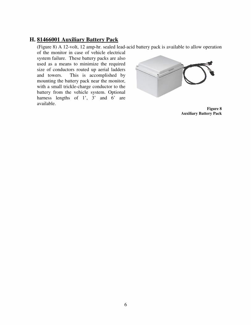
H. 81466001 Auxiliary Battery Pack
(Figure 8) A 12-volt, 12 amp-hr. sealed lead-acid battery pack is available to allow operation
of the monitor in case of vehicle electrical
system failure. These battery packs are also
used as a means to minimize the required
size of conductors routed up aerial ladders
and towers. This is accomplished by
mounting the battery pack near the monitor,
with a small trickle-charge conductor to the
battery from the vehicle system. Optional
harness lengths of 1’, 3’ and 6’ are
available. Figure 8
Auxiliary Battery Pack
7
IV. CONTROL SYSTEM SPECIFICATIONS Controller Specifications
• Power requirements 12VDC (11VDC to 14VDC)
• Control current
• Monitor motor run current for left-right
• Monitor motor run current for up-down
0.15 A
4.5 - 5 A* @ 200psi
4.5 - 5 A* @ 200psi
• Monitor motor stall current 27 A
• Current limit trip-out 12 A
• Nozzle motor run current 0.5 A
• Operating temperature range -40°F (-40°C) to 176°F (80°C)
Shock: • 30 G's (55 Hz. @ .2 inch double amplitude)
Vibration: • 15.5 G's (55 Hz. @ .05 inch double amplitude) continuous operation
Environmental:
• All enclosures have a NEMA 4 rating (must withstand a 1 inch stream of water (65GPM)
from a distance of ten feet for five minutes, with no water entering the enclosure).
Installation Instructions
8
V. INSTALLATION A. Component Mounting
See system layout drawing number 8394040 (part number 98156000) for pictorial of system
layout.
1. Monitor
Attach 4" 150 lb. class ANSI pattern companion flange to water supply pipe so that bolt
pattern will allow monitor to be installed with the "straight ahead" position properly aligned.
Alignment is correct when the "straight ahead" direction is centered between adjacent flange
holes.
Attach monitor inlet flange to companion flange on water supply pipe with eight (8) 5/8-11
UNC grade 5 carbon steel or stainless steel bolts, 2-1/2 inches long, with nuts. If a wafer
type butterfly valve is installed between the monitor and the companion flange, required bolt
length will be 4-1/2 inches. Seal flange joint with gasket, or suitable flange sealant. Most
wafer type butterfly valves have seats that serve as flange gaskets, and separate gaskets or
sealant is not required. Apply Loctite® #242 to bolt threads, then thread on nuts, and torque
to 60-70 ft-lbs.
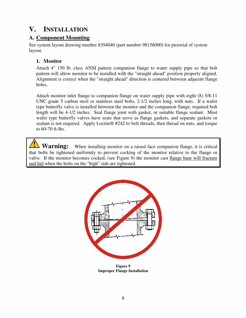
Warning: When installing monitor on a raised face companion flange, it is critical
that bolts be tightened uniformly to prevent cocking of the monitor relative to the flange or
valve. If the monitor becomes cocked, (see Figure 9) the monitor cast flange base will fracture
and fail when the bolts on the "high" side are tightened.
Figure 9
Improper Flange Installation
9
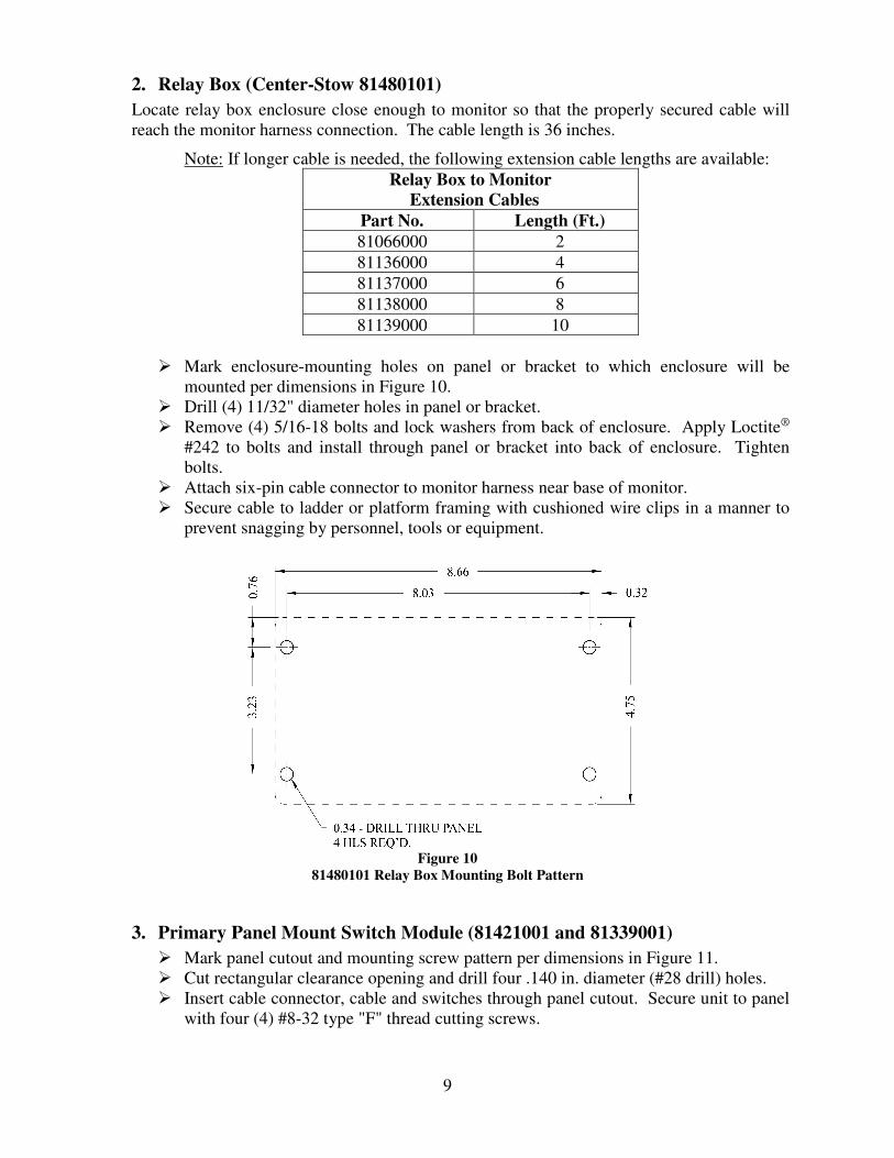
2. Relay Box (Center-Stow 81480101)
Locate relay box enclosure close enough to monitor so that the properly secured cable will
reach the monitor harness connection. The cable length is 36 inches.
Note: If longer cable is needed, the following extension cable lengths are available:
Relay Box to Monitor
Extension Cables
Part No. Length (Ft.)
81066000 2
81136000 4
81137000 6
81138000 8
81139000 10
� Mark enclosure-mounting holes on panel or bracket to which enclosure will be
mounted per dimensions in Figure 10.
� Drill (4) 11/32" diameter holes in panel or bracket.
� Remove (4) 5/16-18 bolts and lock washers from back of enclosure. Apply Loctite®
#242 to bolts and install through panel or bracket into back of enclosure. Tighten
bolts.
� Attach six-pin cable connector to monitor harness near base of monitor.
� Secure cable to ladder or platform framing with cushioned wire clips in a manner to
prevent snagging by personnel, tools or equipment.
Figure 10
81480101 Relay Box Mounting Bolt Pattern
3. Primary Panel Mount Switch Module (81421001 and 81339001)
� Mark panel cutout and mounting screw pattern per dimensions in Figure 11.
� Cut rectangular clearance opening and drill four .140 in. diameter (#28 drill) holes.
� Insert cable connector, cable and switches through panel cutout. Secure unit to panel
with four (4) #8-32 type "F" thread cutting screws.
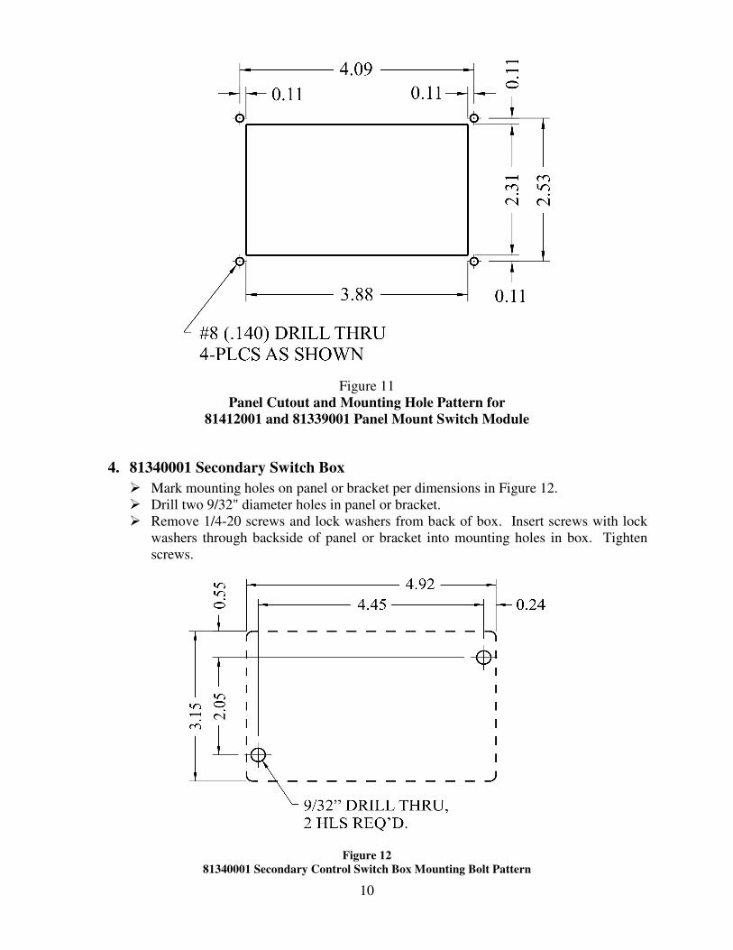
10
Figure 11
Panel Cutout and Mounting Hole Pattern for
81412001 and 81339001 Panel Mount Switch Module
4. 81340001 Secondary Switch Box
� Mark mounting holes on panel or bracket per dimensions in Figure 12.
� Drill two 9/32" diameter holes in panel or bracket.
� Remove 1/4-20 screws and lock washers from back of box. Insert screws with lock
washers through backside of panel or bracket into mounting holes in box. Tighten
screws.
Figure 12
81340001 Secondary Control Switch Box Mounting Bolt Pattern
11
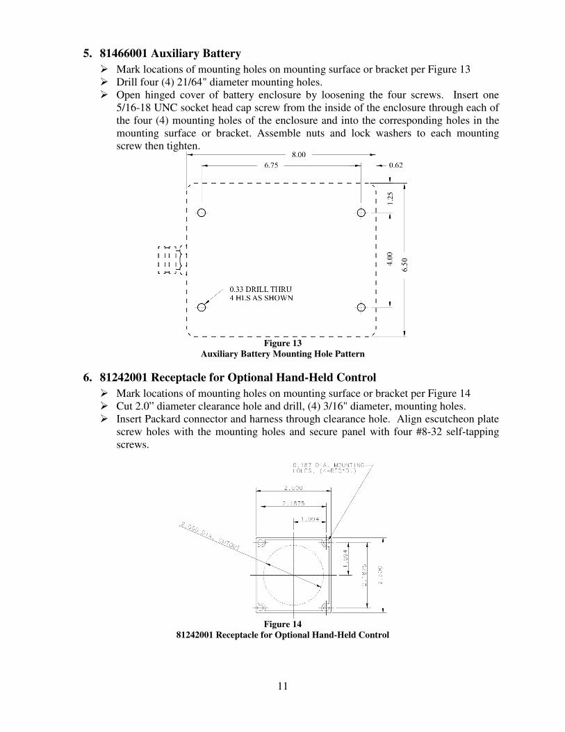
5. 81466001 Auxiliary Battery
� Mark locations of mounting holes on mounting surface or bracket per Figure 13
� Drill four (4) 21/64" diameter mounting holes.
� Open hinged cover of battery enclosure by loosening the four screws. Insert one
5/16-18 UNC socket head cap screw from the inside of the enclosure through each of
the four (4) mounting holes of the enclosure and into the corresponding holes in the
mounting surface or bracket. Assemble nuts and lock washers to each mounting
screw then tighten.
Figure 13
Auxiliary Battery Mounting Hole Pattern
6. 81242001 Receptacle for Optional Hand-Held Control
� Mark locations of mounting holes on mounting surface or bracket per Figure 14
� Cut 2.0” diameter clearance hole and drill, (4) 3/16" diameter, mounting holes.
� Insert Packard connector and harness through clearance hole. Align escutcheon plate
screw holes with the mounting holes and secure panel with four #8-32 self-tapping
screws.
Figure 14
81242001 Receptacle for Optional Hand-Held Control

12
B. Electrical Connections
1. System Wiring Diagrams
Refer to the appropriate wiring diagram (Found in instruction packet 98421001 included with
81480101 Relay Control Module)
� Drawing Number 30189000 (Part Number 98284010) With Stow and OEM supplied
primary controls
� Drawing Number 30194000 (Part Number 98284020) No Stow with Elkhart Brass
supplied primary controls
� Drawing Number 30205000 (Part Number 98284030) With Stow and Elkhart Brass
supplied primary controls
2. Monitor to (81480101 Center-Stow) Relay Control Module
� Route cable with 6-conductor molded connector from 81480001 relay box to
corresponding connector on monitor harness near inlet flange. Plug connector halves
together.
� Use cushioned clamps to secure cable to appropriate structural members, being sure
to locate cable in protected areas.
3. 81339001 Primary Control Switch Module to (81480101 Center-Stow) Relay
Control Module
� Route remaining unused cable from 81480101 relay box to weather proof junction
box (installer supplied). Insert cable through weather proof strain relief into box, and
tighten strain relief nut.
� If junction box is within four feet cable length of 81339001 control switch module,
use Elkhart #36802000 harness assembly. (If cable distance from control switch
module to junction box exceeds four feet, use 36804000 extension harness (10ft.).)
Join Packard Metri-Pak connector on harness to mating connector on switch control
module, and route harness to junction box. Insert harness through weather proof
strain relief fitting into junction box. Strip off suitable length of outer jacket from
both cables in junction box, then strip each individual conductor. Make secure,
insulated splices of matching color wires. Install junction box lid.
� If dual switch modules are required (i.e. one control on each pump panel), see wiring
diagram for required wye harness and extension harness.
4. 81340001 Secondary Switch Box to (81480101 Center-Stow) Relay Control
Module
� Route 9-conductor cable (with warning tag) from relay box to switch box, and secure
cable with cushioned clamps.
� Remove lid from switch box by loosening the four screws at corners, loosen nut on
cable strain relief fitting, and insert cable through fitting approximately 6 inches.
� Strip off outer jacket of cable to a length of 4 inches. Pull cable back through strain
relief so that just 1/4" of the cable jacket protrudes into the box. Tighten strain relief
fitting nut securely.
13
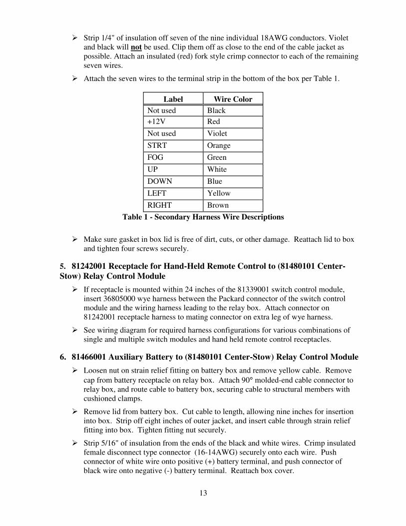
� Strip 1/4" of insulation off seven of the nine individual 18AWG conductors. Violet
and black will not be used. Clip them off as close to the end of the cable jacket as
possible. Attach an insulated (red) fork style crimp connector to each of the remaining
seven wires.
� Attach the seven wires to the terminal strip in the bottom of the box per Table 1.
Label
Wire Color
Not used Black
+12V Red
Not used Violet
STRT Orange
FOG Green
UP White
DOWN Blue
LEFT Yellow
RIGHT Brown
Table 1 - Secondary Harness Wire Descriptions
� Make sure gasket in box lid is free of dirt, cuts, or other damage. Reattach lid to box
and tighten four screws securely.
5. 81242001 Receptacle for Hand-Held Remote Control to (81480101 Center-
Stow) Relay Control Module
� If receptacle is mounted within 24 inches of the 81339001 switch control module,
insert 36805000 wye harness between the Packard connector of the switch control
module and the wiring harness leading to the relay box. Attach connector on
81242001 receptacle harness to mating connector on extra leg of wye harness.
� See wiring diagram for required harness configurations for various combinations of
single and multiple switch modules and hand held remote control receptacles.
6. 81466001 Auxiliary Battery to (81480101 Center-Stow) Relay Control Module
� Loosen nut on strain relief fitting on battery box and remove yellow cable. Remove
cap from battery receptacle on relay box. Attach 90° molded-end cable connector to
relay box, and route cable to battery box, securing cable to structural members with
cushioned clamps.
� Remove lid from battery box. Cut cable to length, allowing nine inches for insertion
into box. Strip off eight inches of outer jacket, and insert cable through strain relief
fitting into box. Tighten fitting nut securely.
� Strip 5/16" of insulation from the ends of the black and white wires. Crimp insulated
female disconnect type connector (16-14AWG) securely onto each wire. Push
connector of white wire onto positive (+) battery terminal, and push connector of
black wire onto negative (-) battery terminal. Reattach box cover.

14
C. Rotational Limits
FOR A DESCRIPTION OF ALL
SETTINGS REFER TO DRAWING
98031050.
Visit
www.elkhartbrass.com
Look under “Service & Parts” then
“Operating and Instruction Manuals”
Figure 15
Rotational Limit Settings for 8394-04

15
VI. OPERATING INSTRUCTIONS A. Normal Operation
The monitor and nozzle are controlled with three toggle switches at each control
point. These switches are marked “STRT-FOG”, “LEFT-RIGHT”, AND “UP-
DOWN”. The switches are of the three position, momentary contact, center-off
type. Simply push and hold the switch(es) to move the monitor to the desired
stream direction, or to adjust the nozzle to the desired spray pattern*. Release
switch when proper stream position or spray pattern is achieved.
B. Manual Override
In the event of power failure to the monitor, the motors may be actuated manually. To
operate a function manually, simply apply a ¾” ratcheting type wrench (either socket type
or ratcheting box end type) to the hex fitting on the motor shaft.
Caution: Do not use impact drivers to operate manual override nuts. Serious damage to motor gear heads
will result.
*Note: The SM-xxxxBE nozzles have a unique ball screw drive that allows the motor to
“free wheel” at the end of pattern travel in either the straight stream or wide fog positions.
No slip clutch or current limiting feature is used with these nozzle drives.
C. Storing the 8394 Monitor (If available)
See document 98284060 (Found in instruction packet 98421001 included with 81480101
Relay Control Module) for a complete description of the operation of the stow feature.
Warning:
Never activate the “Stow” feature while water is flowing. Serious injury to personnel and
damage to apparatus could result.
Note - Any directional command (left, right, up, or down) will cancel the “stow” command.
To continue the command, reactivate the “Stow” feature.
Note – In the event power is cycled in the middle of a stow operation; when the processor
powers up the stow output will show that the monitor is NOT stored.
16
VII. MAINTENANCE & INSPECTION For repair parts information see assembly-drawing number 08394041 (part number 98155000.)
A. Preventive Monitor Maintenance
The complete monitor and control system should be inspected during each apparatus check.
Careful inspection for damage to the monitor or nozzle is especially important after use in
emergency operations.
� Operate each function (left-right, up-down, stream-fog, stow) with each of the
controllers.
� Remove nozzle and check for debris lodged between the nozzle stem and body, or in
the stream shaper inlet. Remove debris.
� During nozzle flow test, inspect monitor swivel joints for leaks.
� With the water off, operate the stow function, looking for any possible obstructions and
check the final stow position.
� Inspect all exposed wiring for signs of damage.
Note: Grease fittings are provided for the up-down and left-right gear cases, routine greasing
should be performed to expel water & other contaminants that can get into the rotation joint
& gear cases. If the monitor is exposed to a high level of radiant heat for a prolonged period,
it may be possible for the factory grease to thin and run out of the gear cases. In such an
event, fresh grease should be applied. Use Mobilux EP2 or equivalent.
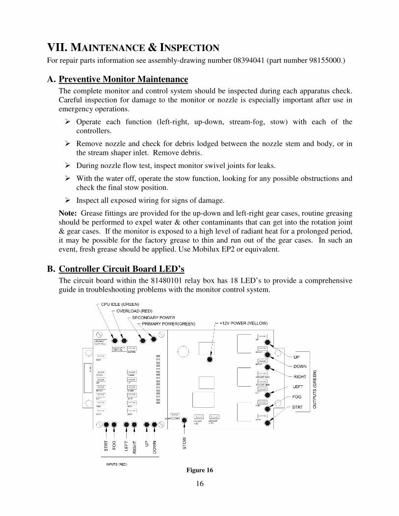
B. Controller Circuit Board LED’s
The circuit board within the 81480101 relay box has 18 LED’s to provide a comprehensive
guide in troubleshooting problems with the monitor control system.
Figure 16

17
LED Locations
LED Label
Color
Signal Significance
+12V Power
Yellow
When lit, 12VDC power is available for operation of unit. If this LED
dims upon activation of a monitor function switch, the power source
has a significant voltage drop due either to low battery charge or
excessive line resistance.
CPU Idle
Green
This LED is located on the small daughter board. When power is
applied to the circuit board, and the “+12V Power” LED is lit, this
LED should also be lit. When lit, 5V power for the logic circuitry is
available. If not lit, replace circuit board.
Overload
Red
This LED is located on the small daughter board. This LED is
normally off. When lit, it signifies that one of the current sensors has
sensed an overload condition and has shut off power to the
corresponding motor. The LED should turn off when the function
switch is released. This device will normally light whenever a
monitor function reaches a travel limit. A low voltage condition at the
power source may also cause this LED to light as a result of increased
motor current at lowered voltage.
Primary
Power
Green
This LED is located on the small daughter board. When power is
applied to the circuit board, and the “+12V Power” LED is lit, this
LED should also be lit. It indicates that power is available to the
primary control switches. If not lit, replace circuit board.
Stow Green
If the P20 jumper is set to do so this LED will blink during the stow
sequence. In either case, the LED will come on continuously once the
unit is stowed. It will remain on until the operator gives a positional
command. The controller will remember the state of the “STOW”
LED even if power is cycled.
Secondary
Power
Green
When power is applied to circuit board, and the “+12V Power” LED
is lit, this LED should also be lit. It indicates that power is available
to the secondary control switches. If not lit, replace circuit board.
Inputs (6)
Red
These LED’s are located on the small daughter circuit board. Each of
these LED’s is normally off. When a function switch is actuated the
corresponding LED lights signifying that the input signal has reached
the circuit board. If an LED fails to light, an open circuit situation
probably exists in the wiring between the relay box and the switch, or
the switch is defective.
Outputs (6) Green
Each of these LED’s is normally off. When a function switch is
actuated, the corresponding LED lights up, signifying that the
appropriate relay has actuated. If an output LED fails to light when
the corresponding input LED is lit and the overload LED is not lit,
replace circuit board.
Table 2 -- LED Descriptions
18
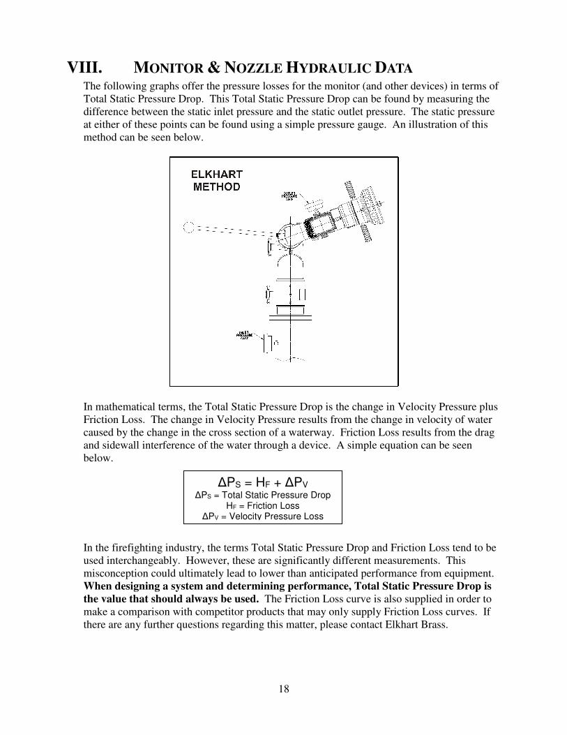
VIII. MONITOR & NOZZLE HYDRAULIC DATA The following graphs offer the pressure losses for the monitor (and other devices) in terms of
Total Static Pressure Drop. This Total Static Pressure Drop can be found by measuring the
difference between the static inlet pressure and the static outlet pressure. The static pressure
at either of these points can be found using a simple pressure gauge. An illustration of this
method can be seen below.
In mathematical terms, the Total Static Pressure Drop is the change in Velocity Pressure plus
Friction Loss. The change in Velocity Pressure results from the change in velocity of water
caused by the change in the cross section of a waterway. Friction Loss results from the drag
and sidewall interference of the water through a device. A simple equation can be seen
below.
In the firefighting industry, the terms Total Static Pressure Drop and Friction Loss tend to be
used interchangeably. However, these are significantly different measurements. This
misconception could ultimately lead to lower than anticipated performance from equipment.
When designing a system and determining performance, Total Static Pressure Drop is
the value that should always be used. The Friction Loss curve is also supplied in order to
make a comparison with competitor products that may only supply Friction Loss curves. If
there are any further questions regarding this matter, please contact Elkhart Brass.
∆PS = HF + ∆PV
∆PS = Total Static Pressure Drop HF = Friction Loss
∆PV = Velocity Pressure Loss

19
Figure 17
8394-04 Spit-Fire Pressure Losses
Figure 18
284-B Stream Shaper Pressure Loss
8394-04 Spit-Fire Losses 4.0” Inlet and 3.5” Outlet
284-B Stream Shaper Losses

DOCUMENT NUMBER
98167050 REVISION - A
ELKHART BRASS MFG. CO., INC. P.O. Box 1127 · 1302 West Beardsley Ave.
Elkhart, Indiana 46515
E-mail: [email protected]
Website: www.elkhartbrass.com
(800) 346-0250