spinal stenosis detection in mri using modular coordinate
TRANSCRIPT

Spinal Stenosis Detection in MRI using ModularCoordinate Convolutional Attention Networks
Uddeshya UpadhyayDept. of Computer Science and Engineering
Indian Institute of Technology-Bombay
Badrinath SinghalSynapsica Technologies
Meenakshi SinghSynapsica Technologies
Abstract—Spinal stenosis is a condition in which a portion ofspinal canal narrows and exerts pressure on nerves that travelthrough it causing pain and numbness that might require surgery.This narrowing can be caused by pathologies in bony structures(vertebrae) or soft tissue structures (intervertebral discs) thatcomprise the spine. Radiography, particularly Magnetic Reso-nance Imaging (MRI) is the modality of choice to evaluate stenosisand intervertebral disc pathology. Radiologists examine axialMRI scans at various levels along the spine to detect stenosis.Further, they evaluate the diameters of spinal canal and bulgingin nearby discs which can indicate narrowing and compressionon nerves. Hence measuring various diameters in a scan is acrucial step in diagnosis. However, affected regions occupy avery small fraction of the scan and there is virtually no room forerror as a deviation of few pixels will also lead to discrepancies inmeasured and original lengths which makes it a very difficult andlaborious task to measure the length of such intricate structuresaccurately. This paper proposes a novel deep learning basedsolution to tackle this problem. Proposed method attempts tosolve it in two independent modules and makes prediction on theenlarged section of the scan which also makes it easier to measurevarious lengths. Human radiologists focus on certain parts ofthe scan rather than attending to the entire scan which largelyconsists of irrelevant background. Proposed modular approachis designed to mimic this attention mechanism. Both modulesare built using coordinate convolutional networks, comparisonswith baseline method empirically demonstrate superiority of theproposed approach.
Index Terms—spinal stenosis, magnetic resonance imaging,deep learning, coordinate convolutions, attention
I. INTRODUCTION
Spinal stenosis is the most common reason for lumbar spinesurgery in patients over 65 years [1]. Given that many patientsare asymptomatic, radiologists rely primarily on MagneticResonance Imaging (MRI) to provide objective evidence ofneurovascular compromise. However, there is recognized vari-ability in description and reporting of spinal stenosis amongradiologists and other physicians making any analysis ofsurgical outcomes less insightful [2]. This variability inspiresthe need for quantitative methods in forming diagnosis. Themost common quantitative method used for this purpose ismeasurement of anteroposterior (AP) diameter of the spinalcanal [2]. This measure is not affected by ageing [3] oncespine reaches adult size and hence is generically applicable.Stenosis is indicated by an AP diameter of canal less than 10mm in cervical spine or 12 mm in lumbar spine.
MRI scans consist of images taken at various sections along3 planes - Coronal (from front), Sagittal (from side) and Axial
(from top down). They create a 3D impression of the regionby stacking 2D images along different planes. In MR imagesAP diameter of canal is typically calculated on axial imagescorresponding to mid-disc levels along the spine. Similarly,foraminal stenosis is established by observing narrowing ofintervertebral foramen, a small hole through which nerves exitthe spinal canal and travel through the body. Diagnosis takesinto account characterization and measurement of AP diameterof spinal canal and foramen over different discs and vertebraepositions.
Measuring canal diameters on MR images is a tedious task,requiring radiologists to accurately place markers provided byDICOM viewer at appropriate locations to get measurement.Multiple measurements corresponding to discs present in thescan are made for a typical report. This paper proposes amethod to automate the process of measuring the diameter ofspinal canal in MRI scans using Convolutional Neural Networkarchitectures. Proposed method divides the problem statementinto two parts, first part is building attention network whichdecides which region to look in the image and the second partworks as the regression model which calculates the diameterof the spinal canal.
Existing work [4] builds similar automation by providingstenosis grading for lumbar spine in 3 classes - Normal,Mild/Moderate, and Severe; and reports class accuracy ofapproximately 80.4. However, medically the general standardis to provide actual measurements in radiology reports, andpractitioners have differing opinions about range of measure-ments that form a particular stenosis grade. Our approach notonly provides measurements of AP diameter of canal but alsois generalized for both lumbar and cervical regions of spinethus giving more freedom to radiologist for diagnosis. Ourbest performing model predicts the diameter of the spinalcanal accurately within 2mm for 85.5% of the test datasetand diameter of foraminal gaps within 2mm for 77.5% of thetest dataset.
II. RELATED WORK
A. Medical Image Analysis with deep learning
Deep learning methods are increasingly used to analysemedical images and related data. Typically deep convolu-tional networks are used for tasks such as classification,segmentation, regression [5]–[9] to achieve some state ofthe art performances. Recent works have shown successful

applications of deep learning methods to biomedical imageanalysis including counting [10], [11], segmentation [12],[13], super-resolution [14], [15]. One such landmark methoddemonstrating successful application of deep learning overa variety of biomedical image analysis task with relativelysmall amount of tagged data was proposed as U-Net [12].The network has been instrumental in tasks such as [16]–[19]. U-Net was built upon Fully Convolutional Networks(FCN) [20] which utilizes only convolutional nets allowingfor processing of arbitrary sized input, it was proposed toperform segmentation. Deep neural networks have also beenused to learn important features and segment out tumor invarious scans [21], [22]. Recently, deep neural networks havealso been employed to reduce required gadolinium dose incontrast-enhanced brain MRI [23]. Cardiac MRI analysis hasalso benefited by deep learning [24], [25]. Deep learning hasalso been used to analyse CT scans and ultrasound images[26]–[29].
In context of spinal MRI analysis there has been significantwork before rise of deep learning which involved the useof classical hand crafted features and various classifiers likeSupport Vector Machines (SVM) [30]–[32]. Most of the priorwork has focused on segmentation in MRI scans [33]–[35].Recently proposed [4] performs the segmentation of the discswhich allows them to process the axial and sagittal scans ofa disc on various levels simultaneously using a pair of deepneural network to grade the cross sectional region of discs onthe basis of seriousness of stenosis.
B. Visual Attention
Retina in human visual system intercepts light coming froma wide range of directions covering a vast area yet humansimplicitly pay attention to a very specific region in the fieldof view, i.e, at any given instant specific region is viewed inhigh-resolution where as the rest of the field of view remainsin low-resolution. As we shift the focus of our eyes, we shiftthe high-resolution region in our field of view. This allowsfor efficient computation by visual cortex system as it onlyprocesses information at a few fixation region, rather thanprocessing the entire scene.
Some of the methods proposed to capture this mechanism indeep neural networks include recurrent attention model (RAM)[36] which formulates the vision problem as a reinforcementlearning problem. Other methods such as Deep recurrentattention model (DRAM) [37] was designed to overcome thelimitations of RAM by introducing additional components likecontext network, classification network and emission network.Enriched deep recurrent attention model (EDRAM) [38] wasproposed as an attempt to eliminate reinforcement learningas used in RAM and DRAM. EDRAM augments the attentionnetwork with spatial transformer [39] and uses a differentiableloss function.
Proposed method takes inspiration from this concept todesign a module capable of extracting “important region”from the MRI scan and further process it to predict thelengths of various structures. However, this method is not
using recurrent networks or reinforcement learning but onlyconvolutional blocks which have shown remarkable featureextraction capability from complex images.
C. Coordinate Convolutions
Recent advancements in convolutional networks have shownthat on the simple task of learning coordinate transforms,i.e., transforms from Cartesian coordinates (x,y) to one-hotvector or vice versa, convolutional neural networks fail [40].However, in the same work it has been shown that alteringthe input to the convolutional layers by including additionalcoordinate related channels help rectify the problem.
(a)
(b) (c) (d)
Fig. 1: (a) Coordinate convolutional layer taking c channelinput and appending 3 different coordinate related channelsand producing output with c′ channels. (b) Radius channel.(c) X channel. (d) Y channel
Various experiments have shown significant improvement invision tasks such as detection, segmentation etc by includingcoordinate convolutions in the pipeline appropriately. Thismethod proposes to generate binary mask to highlight each ofthe specific regions in the scan whose length is to be measured,i.e, spinal canal and foramina. The length of these structurescan be inferred from the predicted masks by measuring it’slength in a particular direction.
This work produces binary masks to calculate the length forseveral regions and coordConv layers are better suited for thistask. Therefore, we design the coordConv version of baselinemodel and show that there is significant improvement in theperformance of the network by comparing appropriate results.
III. METHODS
A. Dataset
The dataset consists of spinal MRI scans from multiplesources with different MRI machines. In this study a total

(a) (b) (c)
Fig. 2: Different samples from training dataset, representing possible input. (a) shows the case where the diameter of leftforamen, right foramen and spinal canal are clearly visible and labelled. (b) shows the case where the left foramen has fused.(c) shows the case where both the foramina have fused
of 944 unique T2-axial MRI scans are used, out of which653 have been used for training and remaining 291 have beenused for testing. There are different MRI machine models fromdifferent manufacturers, specifically, scans come from Siemenswith models C!, Magntom-essenza, Sempra, Skyra; PhillipsMedical Systems with models Achieva, Multiva; GE Medi-cal Systems with models Signa-creator, Signa-excite, Signa-explorer.
Train set consists of 554 scans at magnetic field strengthof 1.5T and 99 scans at 3T. 372 scans are of female patientsand 281 scans are of male patients. 83% of scans are fromSiemens machines, 15.2% of scans are from Phillips MedicalSystems and remaining from GE Medical Systems.
Test set consists of 257 scans at magnetic field strengthof 1.5T and 34 scans at 3T. 168 scans are of female patientsand 123 scans are of male patients. 80.8% of scans are fromSiemens machines, 17.2% of scans are from Phillips MedicalSystems and remaining from GE Medical Systems.
These MRI scans were annotated by a group of professionalradiologists who marked out the diameter for spinal canal andthe narrowest gap between the intervertebral foramen on eitherside of spinal canal (if foramen was visible). Spinal canal isalways visible in every valid scan; however, the narrowing inforamen may not be visible in every scan. Figure 2 shows afew samples from the dataset and various types of annotationwhich are possible.
B. Architecture
Proposed approach to this problem can be split into twoseparate models. First model works as a explicit attentionnetwork and we refer to this part of the pipeline as module 1,this model is used to segment out the “important” region in thescan which encloses spinal canal and foramina (if present). Weuse this output to create a square crop-section. This allows usto focus the downstream computations on “important” regionand avoid possibly noisy signals from the rest of the scanto affect the learning. This is possible because using theavailable annotations it is easy to create required dataset forthe training, by creating a sufficiently large square boundingbox. Fig 3 shows a training sample with the prepared ground
truth (obtained via bounding box enclosing all the lines witha small amount of padding vertically and horizontally).
(a) (b)
Fig. 3: (a-b) example of an input and binary-mask pair usedfor training module 1
This paper proposes a new deep neural network, CoU-netas shown in figure 4, based on U-Net [12] and coordinate con-volution [40]. CoU-Net makes use of coordinate convolutionsby appending the x, y, radius coordinate channels as shown infigure 1, at the beginning and after every max-pooling or up-scaling in the network. The last convolutional layer in module1 outputs a 1 channel binary masks for each of the input scanrepresenting the “important” region in the scan.
Model trained in module 1 learns to output a mask rep-resenting important region, this mask is used to generate asquare bounding box to crop the “important” region from thescan. Interpolation of the smaller cropped output to a largersquare image is done before passing it downstream for furthercomputations.
The interpolated output from module 1 is passed to a secondnetwork to localize various regions, which will eventually leadto the required measurement as explained later. This part ofpipeline is referred as module 2. In this module, we posethe learning task as multi-channel segmentation. Ground truthannotations which are available in form of lines as shownin figure 2, are used to create tight bounding box aroundeach line. Padding is done in horizontal direction to give

Fig. 4: CoU-Net, a modification inspired from U-Net and coordinate convolution.
each of the boxes significant width. No padding is done inthe vertical direction as the length in the vertical direction iscrucial for accurate calculation (length of most of the markingscan be estimated as the difference in coordinates in the verticaldirection). Multi-channel (in this case 3, because there can bea maximum of three boxes) segmentation masks are created,such that each channel corresponds to the binary mask of onlyone annotated line. Channel is zeroed out if a line is missingfrom annotation. Figure 5 shows an example of the trainingsample and corresponding multi-channel masks created fortraining purpose.
(a) (b)
Fig. 5: (a-b) example of an input crop-section and multi-channel mask (represented in RGB) pair used for trainingmodule 2
Since the final reported length depends directly on theprediction of model in module 2, it is essential for this modelto output the maps with high precision. Again CoU-Net is usedto predict the output precisely. However, the last convolutionallayer in module 2 outputs a 3 channel tensor for every inputscan. These 3 channels represents the binary mask for leftforamen, spinal canal and right-foramen. We compare theperformance of CoU-Net with a similar U-Net (without anycoordinate convolution) and demonstrate the superiority ofproposed method.
C. Loss Functions
Let Mi(.; ΘMi) represent deep neural network for modulei with trainable parameters Θi. Let Xk represent input to themodel Mi which produces output Yk, i.e
Yk = Mi(Xk,ΘMi) (1)
Let Yk be the ground truth corresponding to Xk. The followingloss function is used for both module 1 and module 2
L(Yk, Yk) =||Yk − Yk||2
d− λ 2((Yk · Yk) + ε)
(∑
j Yjk +∑
j Yjk) + ε(2)
where flattened Yk is a d dimensional vector, Yjk is jth
coordinate in Yk and ε = 1e−5 is a small constant intro-duced for numerical stability. The first term represents theMean Square Error (MSE) between the ground-truth andthe predicted output, whereas the second term represents thedice score between prediction and the ground-truth. We setλ = 1e−4 a small positive number (obtained empirically). Atthe start of the training loss is dominated by the MSE term, astraining progresses this term reduces in magnitude and in laterepochs of training, loss has significant contribution from thedice score as well. In these experiments, dice score alone tooklonger to converge where as the MSE did not generalize wellfor the pixels at the boundary. We found this combination toprovide much faster convergence and improved performance.
D. Training strategy
Training dataset is augmented by applying five differentlevel of contrasts as well as flipping the images left to right.
Both module 1 and module 2 are trained independentlyand use images and corresponding ground-truth masks ofdimensions 256 × 256 for training. Required length l (inmillimeters) is calculated using
l = s1 · s2 · ps · h (3)
where si refers to the scaling factor introduced due to croppingand re-scaling in module i, ps is the pixel-spacing specified in
(a1)
(b1)
(c1)
(d1)
(a2)
(b2)
(c2)
(d2)
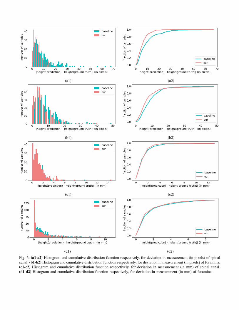
Fig. 6: (a1-a2) Histogram and cumulative distribution function respectively, for deviation in measurement (in pixels) of spinalcanal. (b1-b2) Histogram and cumulative distribution function respectively, for deviation in measurement (in pixels) of foramina.(c1-c2) Histogram and cumulative distribution function respectively, for deviation in measurement (in mm) of spinal canal.(d1-d2) Histogram and cumulative distribution function respectively, for deviation in measurement (in mm) of foramina.
(a1) (b1) (c1) (d1)
(a2) (b2) (c2) (d2)
(a3) (b3) (c3) (d3)
(a4) (b4) (c4) (d4)
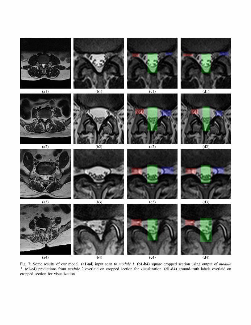
Fig. 7: Some results of our model. (a1-a4) input scan to module 1. (b1-b4) square cropped section using output of module1. (c1-c4) predictions from module 2 overlaid on cropped section for visualization. (d1-d4) ground-truth labels overlaid oncropped section for visualization
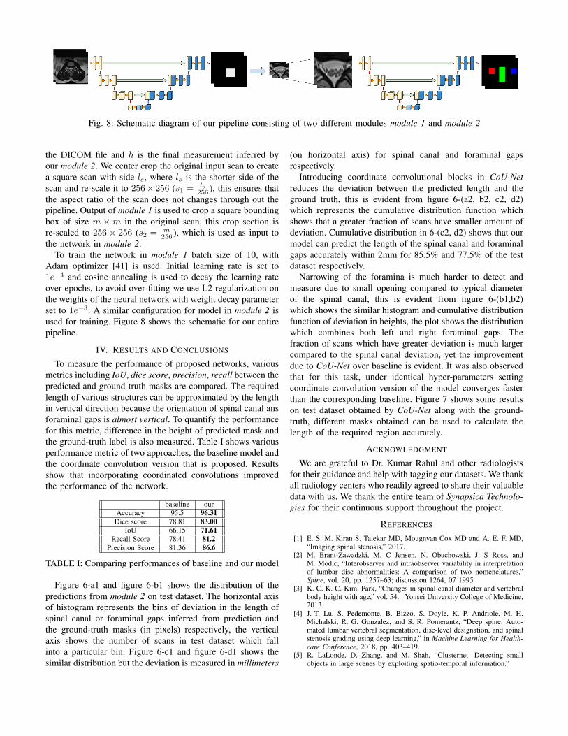
Fig. 8: Schematic diagram of our pipeline consisting of two different modules module 1 and module 2
the DICOM file and h is the final measurement inferred byour module 2. We center crop the original input scan to createa square scan with side ls, where ls is the shorter side of thescan and re-scale it to 256× 256 (s1 = ls
256 ), this ensures thatthe aspect ratio of the scan does not changes through out thepipeline. Output of module 1 is used to crop a square boundingbox of size m ×m in the original scan, this crop section isre-scaled to 256 × 256 (s2 = m
256 ), which is used as input tothe network in module 2.
To train the network in module 1 batch size of 10, withAdam optimizer [41] is used. Initial learning rate is set to1e−4 and cosine annealing is used to decay the learning rateover epochs, to avoid over-fitting we use L2 regularization onthe weights of the neural network with weight decay parameterset to 1e−3. A similar configuration for model in module 2 isused for training. Figure 8 shows the schematic for our entirepipeline.
IV. RESULTS AND CONCLUSIONS
To measure the performance of proposed networks, variousmetrics including IoU, dice score, precision, recall between thepredicted and ground-truth masks are compared. The requiredlength of various structures can be approximated by the lengthin vertical direction because the orientation of spinal canal ansforaminal gaps is almost vertical. To quantify the performancefor this metric, difference in the height of predicted mask andthe ground-truth label is also measured. Table I shows variousperformance metric of two approaches, the baseline model andthe coordinate convolution version that is proposed. Resultsshow that incorporating coordinated convolutions improvedthe performance of the network.
baseline ourAccuracy 95.5 96.31
Dice score 78.81 83.00IoU 66.15 71.61
Recall Score 78.41 81.2Precision Score 81.36 86.6
TABLE I: Comparing performances of baseline and our model
Figure 6-a1 and figure 6-b1 shows the distribution of thepredictions from module 2 on test dataset. The horizontal axisof histogram represents the bins of deviation in the length ofspinal canal or foraminal gaps inferred from prediction andthe ground-truth masks (in pixels) respectively, the verticalaxis shows the number of scans in test dataset which fallinto a particular bin. Figure 6-c1 and figure 6-d1 shows thesimilar distribution but the deviation is measured in millimeters
(on horizontal axis) for spinal canal and foraminal gapsrespectively.
Introducing coordinate convolutional blocks in CoU-Netreduces the deviation between the predicted length and theground truth, this is evident from figure 6-(a2, b2, c2, d2)which represents the cumulative distribution function whichshows that a greater fraction of scans have smaller amount ofdeviation. Cumulative distribution in 6-(c2, d2) shows that ourmodel can predict the length of the spinal canal and foraminalgaps accurately within 2mm for 85.5% and 77.5% of the testdataset respectively.
Narrowing of the foramina is much harder to detect andmeasure due to small opening compared to typical diameterof the spinal canal, this is evident from figure 6-(b1,b2)which shows the similar histogram and cumulative distributionfunction of deviation in heights, the plot shows the distributionwhich combines both left and right foraminal gaps. Thefraction of scans which have greater deviation is much largercompared to the spinal canal deviation, yet the improvementdue to CoU-Net over baseline is evident. It was also observedthat for this task, under identical hyper-parameters settingcoordinate convolution version of the model converges fasterthan the corresponding baseline. Figure 7 shows some resultson test dataset obtained by CoU-Net along with the ground-truth, different masks obtained can be used to calculate thelength of the required region accurately.
ACKNOWLEDGMENT
We are grateful to Dr. Kumar Rahul and other radiologistsfor their guidance and help with tagging our datasets. We thankall radiology centers who readily agreed to share their valuabledata with us. We thank the entire team of Synapsica Technolo-gies for their continuous support throughout the project.
REFERENCES
[1] E. S. M. Kiran S. Talekar MD, Mougnyan Cox MD and A. E. F. MD,“Imaging spinal stenosis,” 2017.
[2] M. Brant-Zawadzki, M. C Jensen, N. Obuchowski, J. S Ross, andM. Modic, “Interobserver and intraobserver variability in interpretationof lumbar disc abnormalities: A comparison of two nomenclatures,”Spine, vol. 20, pp. 1257–63; discussion 1264, 07 1995.
[3] K. C. K. C. Kim, Park, “Changes in spinal canal diameter and vertebralbody height with age,” vol. 54. Yonsei University College of Medicine,2013.
[4] J.-T. Lu, S. Pedemonte, B. Bizzo, S. Doyle, K. P. Andriole, M. H.Michalski, R. G. Gonzalez, and S. R. Pomerantz, “Deep spine: Auto-mated lumbar vertebral segmentation, disc-level designation, and spinalstenosis grading using deep learning,” in Machine Learning for Health-care Conference, 2018, pp. 403–419.
[5] R. LaLonde, D. Zhang, and M. Shah, “Clusternet: Detecting smallobjects in large scenes by exploiting spatio-temporal information.”

[6] H. Hu, J. Gu, Z. Zhang, J. Dai, and Y. Wei, “Relation networks forobject detection.”
[7] L. W. X. B. Z. L. Zhang, Shifeng and S. Z. Li., “Single-shot refinementneural network for object detection,” in Computer Vision and PatternRecognition (CVPR), IEEE, 2018.
[8] C. R. Qi, H. Su, K. Mo, and L. J. Guibas, “Pointnet: Deep learningon point sets for 3d classification and segmentation,” Proc. ComputerVision and Pattern Recognition (CVPR), IEEE, vol. 1, no. 2, p. 4, 2017.
[9] S.-W. Kim, H.-K. Kook, J.-Y. Sun, M.-C. Kang, and S.-J. Ko, “Parallelfeature pyramid network for object detection,” in Proceedings of theEuropean Conference on Computer Vision (ECCV), 2018, pp. 234–250.
[10] W. Xie, J. A. Noble, and A. Zisserman, “Microscopy cell countingand detection with fully convolutional regression networks,” Computermethods in biomechanics and biomedical engineering: Imaging &Visualization, vol. 6, no. 3, pp. 283–292, 2018.
[11] T. Chen and C. ChefdHotel, “Deep learning based automatic immunecell detection for immunohistochemistry images,” in International Work-shop on Machine Learning in Medical Imaging. Springer, 2014, pp.17–24.
[12] O. Ronneberger, P. Fischer, and T. Brox, “U-net: Convolutional networksfor biomedical image segmentation,” in International Conference onMedical image computing and computer-assisted intervention. Springer,2015, pp. 234–241.
[13] D. Ciresan, A. Giusti, L. M. Gambardella, and J. Schmidhuber, “Deepneural networks segment neuronal membranes in electron microscopyimages,” in Advances in neural information processing systems, 2012,pp. 2843–2851.
[14] J. Kim, J. Kwon Lee, and K. Mu Lee, “Accurate image super-resolutionusing very deep convolutional networks,” in Proceedings of the IEEEconference on computer vision and pattern recognition, 2016, pp. 1646–1654.
[15] W. Shi, J. Caballero, F. Huszar, J. Totz, A. P. Aitken, R. Bishop,D. Rueckert, and Z. Wang, “Real-time single image and video super-resolution using an efficient sub-pixel convolutional neural network,” inProceedings of the IEEE Conference on Computer Vision and PatternRecognition, 2016, pp. 1874–1883.
[16] T. Falk, D. Mai, R. Bensch, O. Cicek, A. Abdulkadir, Y. Marrakchi,A. Bohm, J. Deubner, Z. Jackel, K. Seiwald et al., “U-net: deep learningfor cell counting, detection, and morphometry,” Nature methods, p. 1,2018.
[17] P. Esser, E. Sutter, and B. Ommer, “A variational u-net for conditionalappearance and shape generation,” in CVPR, 2018.
[18] K. Sirinukunwattana, J. P. Pluim, H. Chen, X. Qi, P.-A. Heng, Y. B.Guo, L. Y. Wang, B. J. Matuszewski, E. Bruni, U. Sanchez, A. Bhm,O. Ronneberger, B. B. Cheikh, D. Racoceanu, P. Kainz, M. Pfeiffer,M. Urschler, D. R. Snead, and N. M. Rajpoot, “Gland segmentationin colon histology images: The glas challenge contest,” MedicalImage Analysis, vol. 35, pp. 489 – 502, 2017. [Online]. Available:http://www.sciencedirect.com/science/article/pii/S1361841516301542
[19] O. Cicek, A. Abdulkadir, S. S. Lienkamp, T. Brox, and O. Ronneberger,“3d u-net: learning dense volumetric segmentation from sparse anno-tation,” in International Conference on Medical Image Computing andComputer-Assisted Intervention. Springer, 2016, pp. 424–432.
[20] J. Long, E. Shelhamer, and T. Darrell, “Fully convolutional networksfor semantic segmentation,” in Proceedings of the IEEE conference oncomputer vision and pattern recognition, 2015, pp. 3431–3440.
[21] V. A. Srgio Pereira, Adriano Pinto and C. A. Silva, “Brain tumorsegmentation using convolutional neural networks in mri images,” inIEEE Transactions on Medical Imaging. IEEE, 04 March 2016, pp.1240 – 1251.
[22] M. Havaei, A. Davy, D. Warde-Farley, A. Biard, A. Courville, Y. Bengio,C. Pal, P.-M. Jodoin, and H. Larochelle, “Brain tumor segmentation withdeep neural networks,” Medical image analysis, vol. 35, pp. 18–31, 2017.
[23] W. M. Gong E, Pauly JM and Z. G, “Deep learning enables reducedgadolinium dose for contrast-enhanced brain mri.” in J Magn ResonImaging 2018, 2018, p. 330340.
[24] W. Bai, M. Sinclair, G. Tarroni, O. Oktay, M. Rajchl, G. Vaillant, A. M.Lee, N. Aung, E. Lukaschuk, M. M. Sanghvi, F. Zemrak, K. Fung,J. M. Paiva, V. Carapella, Y. J. Kim, H. Suzuki, B. Kainz, P. M.Matthews, S. E. Petersen, S. K. Piechnik, S. Neubauer, B. Glocker,and D. Rueckert, “Automated cardiovascular magnetic resonance imageanalysis with fully convolutional networks,” Journal of CardiovascularMagnetic Resonance, vol. 20, no. 1, p. 65, Sep 2018. [Online].Available: https://doi.org/10.1186/s12968-018-0471-x
[25] O. Bernard, A. Lalande, C. Zotti, F. Cervenansky, X. Yang, P.-A.Heng, I. Cetin, K. Lekadir, O. Camara, M. A. G. Ballester et al.,“Deep learning techniques for automatic mri cardiac multi-structuressegmentation and diagnosis: Is the problem solved?” IEEE Transactionson Medical Imaging, 2018.
[26] P. Lobo and S. Guruprasad, “Classification and segmentation techniquesfor detection of lung cancer from ct images,” in 2018 InternationalConference on Inventive Research in Computing Applications (ICIRCA).IEEE, 2018, pp. 1014–1019.
[27] A. M. Rossetto and W. Zhou, “Deep learning for categorization oflung cancer ct images,” in Proceedings of the Second IEEE/ACMInternational Conference on Connected Health: Applications, Systemsand Engineering Technologies. IEEE Press, 2017, pp. 272–273.
[28] H. Sugimori, “Classification of computed tomography images in differ-ent slice positions using deep learning,” Journal of healthcare engineer-ing, vol. 2018, 2018.
[29] L. J. Brattain, B. A. Telfer, M. Dhyani, J. R. Grajo, and A. E. Samir,“Machine learning for medical ultrasound: status, methods, and futureopportunities,” Abdominal Radiology, vol. 43, no. 4, pp. 786–799, 2018.
[30] S. Ghosh, M. R. Malgireddy, V. Chaudhary, and G. Dhillon, “A new ap-proach to automatic disc localization in clinical lumbar mri: combiningmachine learning with heuristics,” in Biomedical Imaging (ISBI), 20129th IEEE International Symposium on. IEEE, 2012, pp. 114–117.
[31] Z. Peng, J. Zhong, W. Wee, and J.-h. Lee, “Automated vertebra detectionand segmentation from the whole spine mr images,” in Engineering inMedicine and Biology Society, 2005. IEEE-EMBS 2005. 27th AnnualInternational Conference of the. IEEE, 2006, pp. 2527–2530.
[32] M. Lootus, T. Kadir, and A. Zisserman, “Vertebrae detection andlabelling in lumbar mr images,” in Computational methods and clinicalapplications for spine imaging. Springer, 2014, pp. 219–230.
[33] D. Gaweł, P. Głowka, T. Kotwicki, and M. Nowak, “Automatic spinetissue segmentation from mri data based on cascade of boosted classifiersand active appearance model,” BioMed research international, vol. 2018,2018.
[34] C. Ling, W. M. Diyana, W. Zaki, A. Hussain, and H. A. Hamid, “Semi-automated vertebral segmentation of human spine in mri images,” inAdvances in Electrical, Electronic and Systems Engineering (ICAEES),International Conference on. IEEE, 2016, pp. 120–124.
[35] P. D. Barbieri, G. V. Pedrosa, A. J. M. Traina, M. H. Nogueira-Barbosa et al., “Vertebral body segmentation of spine mr images usingsuperpixels,” in International Symposium on Computer-Based MedicalSystems, 28th. Institute of Electrical and Electronics Engineers–IEEE,2015.
[36] V. Mnih, N. Heess, A. Graves et al., “Recurrent models of visualattention,” in Advances in neural information processing systems, 2014,pp. 2204–2212.
[37] J. L. Ba, V. Mnih, and K. Kavukcuoglu, “Multiple object recognitionwith visual attention,” context, vol. 2, no. l3, p. l4.
[38] A. Ablavatski, S. Lu, and J. Cai, “Enriched deep recurrent visualattention model for multiple object recognition,” in 2017 IEEE WinterConference on Applications of Computer Vision (WACV). IEEE, 2017,pp. 971–978.
[39] M. Jaderberg, K. Simonyan, A. Zisserman et al., “Spatial transformernetworks,” in Advances in neural information processing systems, 2015,pp. 2017–2025.
[40] R. Liu, J. Lehman, P. Molino, F. P. Such, E. Frank, A. Sergeev, andJ. Yosinski, “An intriguing failing of convolutional neural networks andthe coordconv solution,” in Advances in Neural Information ProcessingSystems, 2018, pp. 9628–9639.
[41] P. Kingma and J. Ba., “Adam: A method for stochastic optimization,”in In International Conference in Learning Representations, 2015.