spin test - the ability of spin test method usage in thrusters' fault detection ... · spin...
TRANSCRIPT

Journal of KONES Powertrain and Transport, Vol. 21, No. 4 2014
SPIN TEST - THE ABILITY OF SPIN TEST METHOD USAGE IN THRUSTERS' FAULT DETECTION AND ISOLATION
Rolls-Royce Poland Sp. z o.o.
Kontenerowa Street 8, 81-155 Gdynia e-mail: [email protected]
, ,
Gdynia Maritime University, Faculty of Marine Engineering
Morska Street 81-87, 81-225 Gdynia, Poland tel.: +48 58 6901480, fax: +48 58 6901399
e-mail: [email protected], [email protected], [email protected]
Abstract In the article below, we presented the possibility of „spin test“ method usage for medium rotational speed devices
such as thrusters', which are used to enhance the maneuverability of maritime vessels. The reason for the analysis is the problem of eliminating the unwanted vibrations of thruster's propeller with commonly used methods. It is an innovative solution for accurate verification of the technical condition of screw propellers, which are the most common devices used as the propelling element of thrusters. In the introduction the possibility of thruster's diagnosis using „spin test“ has been described. Commonly used thrusters' and their working conditions were presented. In order to properly assess the technical condition of rotational speed devices, such as thrusters' propellers after their production or renovation it is vital to provide an additional diagnosis in the environment similar to working conditions. Secondly, the problem of spinning parts' vibration was described. „Spin test“ method presented here gives the ability of detailed analysis of spinning parts' vibration. The idea of a compact and easy to assemble station enabling to conduct such research has been shown. The station not only allows to measure the eigenfrequency of vanes' in normal mode and compare it with the previously calculated ones, but also enables material's endurance testing at speeds higher than nominal speed. Finally, we presented the range of using this method in different fields along with the benefits of ‘Spin Tests’.
Keywords: spin test, thrusters' propeller, vibration, ability, speed
Maneuvering a ship is difficult and complex, this is due to its large mass and the distinctive environment of water. It is vital to design a suitable control system of the unit in order to enable precise steering and thereby, to ensure, above all, the safety of navigation. Besides the flap rudder located on the aft, the answer to these requirements are thrusters, even though they are only an auxiliary device, used primarily to maneuver in narrow aisles, canals and ports. Bow thruster is a basic example of such device, it's usually installed below the water line, in a tunnel located transverse to the vessel. Thrusters are commonly used due to their direct impact on the increase of maneuverability, especially at low speed. Conducting a static test of the propeller of propulsion thruster enable us to determine the quality of its geometric performance, correctness of embedding in the bearing or keeping the dimensional tolerances with respect to the model data. Unfortunately, in this way, it is not possible to assess how the propeller of propulsion thruster will behave after being put into rotation when particular points will be burdened with huge forces resulting from its mass, angular acceleration and rotary motion with variable speeds. The method of Spin Test turns out to be the solution to this problem.
ISSN: 1231-4005 e-ISSN: 2354-0133 ICID: 1130468 DOI: 10.5604/12314005.1130468

L. Iwanicki, L. D. Kozyra, R. Tarsa
As mentioned above, thrusters (Fig. 1) are a very significant element of the ship control system.
Fig. 1. Ship’s bow thruster
Depending on the design, purpose and size of the units, there is always a right amount of
thrusters installed, either on the bow, stern or in both places at once. An important parameter is the distance from the thruster to the axis of rotation of the vessel, the longer the distance the greater the produced torque. To achieve maximum efficiency with minimum energy loss, the thruster must be adequately submerged in order to avoid air centrifugation when the ship is not fully immersed. There is a great diversity of thrusters with different propulsion systems, propeller types and control systems.
The division on the basis of propulsion system: electric, hydraulic, combustion engine (rarely used).
The division on the basis of propeller type: fixed pitch propeller, variable pitch propeller, cycloidal propeller.
Every type of propulsion and propeller has its own advantages and disadvantages, which determines their use in a particular construction solution, however it will not be analysed in this study. The hull of the ship, moving in the aquatic environment, generates multiple zones of hydrostatic pressures that adversely affect the work of thrusters. To counteract this, an additional passive tunnel is installed behind the rudder. It reduces the pressure difference on both sides of the hull by allowing a constant flow of water, the effect of which is the increase in the efficiency of the rudder. It can also be put it in the „Y“ or „T“ shaped tunnel which is also beneficial for its effectiveness.
178
Spin Test - The Ability of Spin Test Method Usage in Thrusters' Fault Detection and Isolation
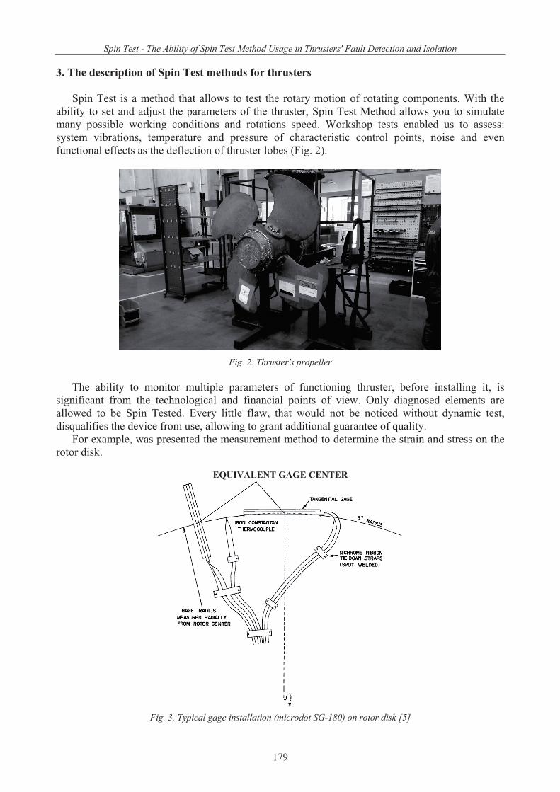
Spin Test is a method that allows to test the rotary motion of rotating components. With the ability to set and adjust the parameters of the thruster, Spin Test Method allows you to simulate many possible working conditions and rotations speed. Workshop tests enabled us to assess: system vibrations, temperature and pressure of characteristic control points, noise and even functional effects as the deflection of thruster lobes (Fig. 2).
Fig. 2. Thruster's propeller
The ability to monitor multiple parameters of functioning thruster, before installing it, is
significant from the technological and financial points of view. Only diagnosed elements are allowed to be Spin Tested. Every little flaw, that would not be noticed without dynamic test, disqualifies the device from use, allowing to grant additional guarantee of quality.
For example, was presented the measurement method to determine the strain and stress on the rotor disk.
EQUIVALENT GAGE CENTER
Fig. 3. Typical gage installation (microdot SG-180) on rotor disk [5]
179

L. Iwanicki, L. D. Kozyra, R. Tarsa
Figure 3 shows the method of measuring the rotor disc using the gage. When the data indicated a sharp change in strain, it was attempted to locate these changes relative to points of changing geometry, such as at the tangent points and at the outer radius of the parallel face lugs. The radial
strain at the disk inner radius ( 2.0/ mrr ) was not measured but was determined from the compatibility equations (given below) and the condition of zero radial stress at this radius.
The strain curves were established, stresses were determined with the compatibility relations for two-dimensional stress [5].
trrE
21, (1)
rttE
21, (2)
where:
r radial stress, MPa,
t tangential stress, MPa,
r radil strain,
t tangential strain, E Young`s modulus, MPa,
Poisson`s ratio. Using these relationships, radial and tangential stresses were calculated at each radius where
strains were measured, as well as at several intermediate radii. The centrifugal stresses in a disk with constant mass density rotating with the angular velocity are proportional to the quantity
2 . A thin rotating ring of the disk material with radius r has the hoop stress [5]:22
mR r . (3) Hence, the measured disk stresses can be presented in dimensionless form as ratios with
respect to R . For convenience the radius mr is taken as the mean radius of the turbine blading.Then [5]:
mm420"5.16mr , 3m/kg7693 ,
angular velocity, rad/s. The stresses calculated by Eqs. 1 and 2, divided by R , are plotted in Fig. 4 and 5 as functions
of the radius ratio mrr / [5]. These curves can be used to determine the centrifugal stresses in all geometrically similar
rotors with different material densities that operate at arbitrary rotational speeds. 4.
Spin Test station (Fig. 6) is an independent device that allows you to assess the model assumptions of propeller of propulsion thruster in practice. The position must be stationary in order to ensure a constant and massive support for working elements that achieve relatively large mass and dimensions.
Spin Test device includes independent systems that ensure proper operation and reliability of the device: Drive System Cooling and lubrication system
180

Spin Test - The Ability of Spin Test Method Usage in Thrusters' Fault Detection and Isolation
Measuring systems Flushing system
Test parameters are stored on the hard drive which enables further, detailed analysis of propeller behaviour.
Fig. 4. Dimensionless centrifugal stresses on first-stage disk (stress distributions based on estimated strains are shown by broken lines) from 4000 rpm test data [5]
Fig. 5. Dimensionless centrifugal stresses on second-stage disk (stress distributions based on estimated strains are shown by broken lines) [5]
181

L. Iwanicki, L. D. Kozyra, R. Tarsa
Fig. 6. Spin Test station
The Spin Test method is an innovative way to verify the technical condition of propellers of propulsion thrusters, both from a technical and economic point of view. Assessing the propeller behavior during the rotation, before installing it in the target object, gives the possibility of diagnosis that is not available during the static test. We are able to simultaneously observe the pressure, temperature, vibration and acoustic trends of individual measurement points. Moreover, this is the only possible way of comparing the model data with the real data obtained during the test. Mentioned data are stored in the measurement card on a regular basis. Flaws detected in this way verify the design intent and the quality of the propeller, which allows the manufacturer to give the recipient a full guarantee of the final product. Spin test, gives the ability to detect the faults before mounting the unit on a ship along being beneficial from an economic point of view, which is also a vital factor in determining the reasonableness of this method.
[1] Dymarski, Cz., Wieliczko, L., Nalewajski, A., Analiza techniczna i st
strumieniowych, 42-44, pp. 3-17, . [2] , M., , PWN, Warszawa 2010. [3] Technical documentation, bow thrusters of Rolls-Royce company. [4] , W., Pracy na Darze M i
Horyzoncie II, Zeszyt Naukowy Akademii Morskiej w Gdyni Nr 69, pp. 123-133, Gdynia 2011.
[5] Vavra, M. H., Hammer, J. E., Bell, E. L., Spin Test of Turbine, NASA Contractor Report, Monterey, California 1972.
182