spiked shear vane — a new tool for measuring peatland top layer … · 2013-12-27 · spiked...
TRANSCRIPT

113Suo 64(2–3) 2013© Suoseura — Finnish Peatland Society ISSN 0039-5471Helsinki 2013 Suo 64(2–3): 113–118 — Reviews
Spiked shear vane — a new tool for measuring peatland top layer strengthPiikkisiipikaira — uusi väline turvemaan pintakerroksen lujuuden mittaukseen
Jari Ala-Ilomäki
Measuring the top layer strength of peatlandsThe trafficability of peatland with vegetation usu-ally relies on the reinforcing effect of plants and their roots in the top layer, typically reaching from 0 to 250 mm. The strength of the decomposed peat layer below the top layer is usually inadequate for vehicular traffic and the environmental impact of breaking the top layer is often considered unac-ceptable. This is especially true in forestry appli-cations, where gross vehicle mass may reach 35 t.
Measuring the peatland top layer, also called the root mat, strength for field experiments has been a problem in the past. Such a measuring device should preferably be manually operated or light enough to be transported manually, and, most importantly, it should be capable of detecting the combined strength of the single reinforcing elements in the root mat.
Many tools designed for mineral soils fail to fulfil these requirements. The blades of a con-ventional shear vane (Kogure et al. 1988), shear annulus (Bekker 1969) or vane-cone (Yong & Youssef 1978) effectively cut the reinforcing root mat, and are thus unable to measure its full intact strength. The cone of a penetrometer (ASAE… 2006) is, due to its form and size, prone to find its way through the root mat without breaking the essential plant parts and measuring their contribution to its strength (Yong et al. 1984,
Ala-Ilomäki et al. 2011). Plate load devices have been successfully used on peatland, yet manually operated versions tend to be cumbersome (Lee & Jarret 1978) and motorised ones are normally mounted on a vehicular platform (Bekker 1969, Alger 1988, Wong 1989, Ala-Ilomäki 2006). Both approaches result in limitations for many field study applications.
The aim of this work was to develop a manual portable tool for measuring the strength of peat-land root mat for trafficability and mobility stud-ies, and to test its applicability.
Development of the toolShear properties of the root mat of peatland are mainly determined by the tensile strength of the roots and other parts of plants in the layer. To avoid cutting them, a spiked shear vane, inspired by the muskeg fluke (Radforth 1969), was de-veloped. In the vane head design (Figure 1), the blades of a conventional shear vane are replaced by rows of evenly pitched vertical steel spikes, attached perpendicular to a circular steel plate. The tips of the steel spikes are tapered to ease penetration into the root mat while causing mini-mal damage to the plant parts. The steel plate is welded to a 1 m long steel tube with a 40 mm outer diameter and a wall thickness of 3 mm. A nut is welded to the upper end of the tube to facilitate rotation with a torque wrench.

114 Jari Ala-ilomäki
To insert the spikes of the vane head into the root mat, the device is hit perpendicularly against the peatland surface. Adequate force may be applied to facilitate the compression of any loose material, such as living moss, on top of the peatland. The device is rotated manually using a Snap-on Techangle ATECH3FR250 torque wrench, equipped with strain gauge measurement of torque and gyroscopic measurement of angular rotation. The torque range of the wrench is 17.5 to 340.0 Nm with ±2% accuracy when measur-ing clockwise at 20 to 100% of full scale. The accuracy of the angular measurement is ±1% of reading, ±1 º. The vertical tube between the shear head and the torque wrench was dimensioned ad-equately to omit its torsion angle during operation.
The first prototype of the spiked shear vane was designed for measurement of shear strength. Manual operation set obvious limits to the torque available, and the shear head was dimensioned accordingly. The length of the 11 mm diameter
spikes was 150 mm. The outer diameter of the blade-shaped array of evenly spaced spikes was 98 mm. There were two spikes per blade with one spike in the centre, resulting in a total of nine spikes. The device was rotated until the breakup point of the root mat was reached. The action resulted in a cylindrical sheared specimen. The maximum torque was recorded by the operator. Detecting the point of breakup was not always straightforward. The specimen usually got stuck between the spikes and removing it manually was tedious and time-consuming.
Based on the experience gained from the first prototype, the device was developed further to measure shear modulus instead of shear strength. This was due to the fact that although the ulti-mate strength of, for example, wet peatland with Sphagnum peat is surprisingly high, it is reached at considerable deformation. This in turn usually results in excessive vehicle sinkage. With shear modulus, the magnitude of deformation directly affects the measured strength value. The strain applied is well below shear strength, which al-lowed for the dimensions of the shear head to be increased in accordance with limits set by the manually applied torque. Larger head diameter aids in measuring the true strength of the root mat, as the spikes have more sparse spacing and bigger roots may fit between them. Larger head diameter is less prone to spatial micro variations in soil strength, which is typical for forest-covered peatlands in Finland.
In the second prototype, the length of the 12 mm diameter spikes was 170 mm and the outer diameter of the array 200 mm. With three spikes per blade and one spike in the middle, the total number of spikes was 13.
Shear stress acts on the walls and the lower plane of the cylindrical specimen and integrating it over these areas results in measured torque. Shear strength is obtained by solving the inte-gral and substituting measured torque according to Equation 1. Shear modulus is a quotient of prevailing shear stress under the limit of propor-tionality and the tangent of corresponding angle of rotation (Equation 2). On shallow peat deposits or when the shear head meets an obstacle, the device may not fully penetrate the peat, and height H in Equation 1 must be set accordingly.
Figure 1. The head of the spiked shear vane. The blades of a conventional shear vane are replaced by rows of tapered steel spikes.Kuva 1. Piikkisiipikairan leikkauspäässä tavallisen sii-pikairan levyt on korvattu riveihin asetelluilla, päistään teroitetuilla teräspiikeillä.
115Suo 64(2–3) 2013
)3(23
2 HRRT
⋅+⋅⋅⋅=
πτ
(1)
ατ
tan=G
(2)
where G = Shear modulus, kPaH = Height of sheared specimen, mR = Radius of sheared specimen, mT= Torque, Nmα = Angle of rotation, radτ = Shear stress, kPa
Practical experienceIn some recent studies conducted by the Finn-ish Forest Research Institute, the spiked shear vane was tested by measuring peatland top layer strength (Ala-Ilomäki et al. 2011, Ala-Ilomäki et al. 2012, Lindeman et al. 2012, Uusitalo & Ala-Ilomäki 2012, Sirén et al. 2013b).The de-vice was remarkably easy to use as the operator only needed to increase the load steadily until a sufficient rotation angle from 5 to 15 degrees, displayed on the LCD display of the wrench, was reached. Normally this corresponds to a torque in the region of 100 Nm, which was felt in the muscles when reached. Measurements were easy to perform in a constant manner. The ease of operation was found to be superior to a manually operated electronically measuring penetrometer of commercial manufacture and a prototype of a manual plate load device developed earlier at the Finnish Forest Research Institute.
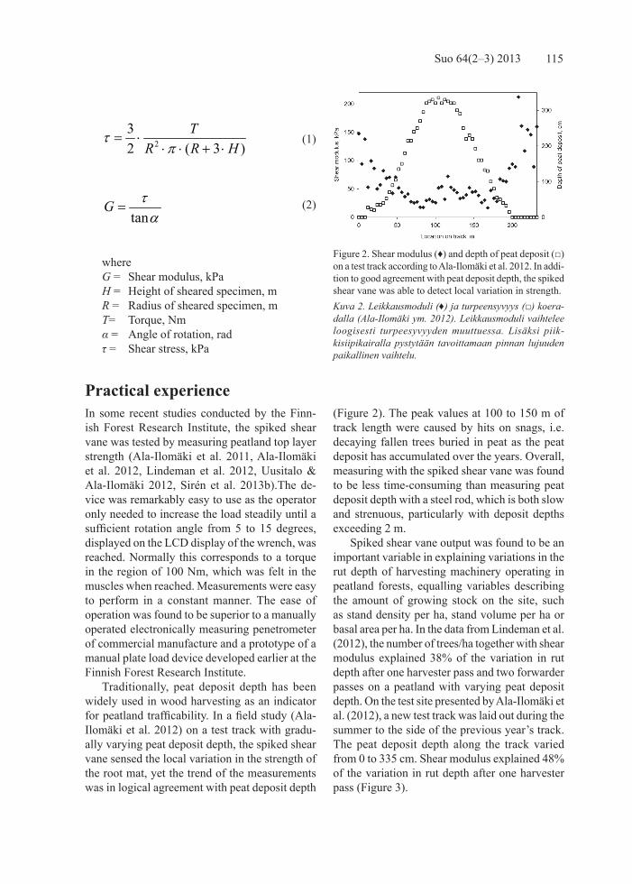
Traditionally, peat deposit depth has been widely used in wood harvesting as an indicator for peatland trafficability. In a field study (Ala-Ilomäki et al. 2012) on a test track with gradu-ally varying peat deposit depth, the spiked shear vane sensed the local variation in the strength of the root mat, yet the trend of the measurements was in logical agreement with peat deposit depth
(Figure 2). The peak values at 100 to 150 m of track length were caused by hits on snags, i.e. decaying fallen trees buried in peat as the peat deposit has accumulated over the years. Overall, measuring with the spiked shear vane was found to be less time-consuming than measuring peat deposit depth with a steel rod, which is both slow and strenuous, particularly with deposit depths exceeding 2 m.
Spiked shear vane output was found to be an important variable in explaining variations in the rut depth of harvesting machinery operating in peatland forests, equalling variables describing the amount of growing stock on the site, such as stand density per ha, stand volume per ha or basal area per ha. In the data from Lindeman et al. (2012), the number of trees/ha together with shear modulus explained 38% of the variation in rut depth after one harvester pass and two forwarder passes on a peatland with varying peat deposit depth. On the test site presented by Ala-Ilomäki et al. (2012), a new test track was laid out during the summer to the side of the previous year’s track. The peat deposit depth along the track varied from 0 to 335 cm. Shear modulus explained 48% of the variation in rut depth after one harvester pass (Figure 3).
Figure 2. Shear modulus (♦) and depth of peat deposit (□) on a test track according to Ala-Ilomäki et al. 2012. In addi-tion to good agreement with peat deposit depth, the spiked shear vane was able to detect local variation in strength.Kuva 2. Leikkausmoduli (♦) ja turpeensyvyys (□) koera-dalla (Ala-Ilomäki ym. 2012). Leikkausmoduli vaihtelee loogisesti turpeesyvyyden muuttuessa. Lisäksi piik-kisiipikairalla pystytään tavoittamaan pinnan lujuuden paikallinen vaihtelu.

116 Jari Ala-ilomäki
The importance of stand properties for peat-land strength is due to the reinforcing effect of tree roots. A proportion of tree roots are of a diameter that is too large to fit between the spikes of the vane. Small tree roots and dwarf scrub roots, sensed by the spiked shear vane, are great in number and make an important contribution to top layer strength. In Uusitalo & Ala-Ilomäki (2012), shear modulus measured with the spiked shear vane had a statistically significant correlation of 0.58 with the amount of living roots in the surface layer of peatland. The output of the spiked shear vane is a true measured strength characteristic of the top layer and can be used directly for physi-cal calculus, whereas variables describing stand properties are indirect in nature. As a result, the spiked shear vane has also been successfully used on mineral soil covered by an organic layer with tree roots (Sirén et al. 2013a).
Further development needsThe most obvious need for improvements on the spiked shear vane is associated with data collect-ing, storage and processing. Presently the operator reads the raw data from the display of the torque wrench and stores it manually, so final strength
values are not readily available. A torque wrench facilitating electronic data transfer to a PC is available from the manufacturer, yet it currently lacks the angular measurement feature.
The physical size of the vane head is another possible subject worth further experimentation. Manual operation sets obvious limits to the torque available, yet increasing the diameter of the head would yield a truer estimation of the top layer strength in the scale of tyre or track contact path. With a larger head, hitting an obstacle and preventing full penetration of the spikes would of course be more likely. Longer spikes would meet the torque limit more easily, and at least on typical Finnish peatland, spikes of approximately 250 mm in length would be ideal. The material and dimensions of the spikes and the base plate would have to be selected accordingly, since longer spikes are subject to higher stress. The probability of hitting obstacles naturally increases with longer spikes.
Thirdly, reducing the weight of a manually operated device is always desirable. This could be accomplished to some extent by using a thinner-walled tube between the wrench and the vane head, and taking its torsion angle into account.
ConclusionsThe spiked shear vane device facilitates relatively fast manual in-situ measurement of peatland top layer strength. To the author’s knowledge, it is the first tool available for this particular purpose. The device is relatively inexpensive and easy to build, therefore easily achievable for interested parties. In recent field trials, it produced relevant strength estimations. Suggested development steps would further increase its practicality.
It is a fact, however, that the output of spiked shear vane measurement only describes strength prevailing in a very small area. Therefore, a large number of measurements are necessary to fully describe the variation in the top layer strength of a harvesting site, for example. The application possibilities of the tool in operational work are therefore limited, and its main field of use is in research.
Figure 3. Rut depth as a function of shear modulus after one harvester pass on a test track with peat deposit depth varying from 0 to 335 cm.Kuva 3. Raiteen syvyyden riippuvuus leikkausmodulista harvesterin yhden ajokerran jälkeen koeradalla, jossa turpeensyvyys vaihteli 0…335 cm.

117Suo 64(2–3) 2013
References
Ala-Ilomäki, J. 2006. The effect of weather con-ditions on the trafficability of unfrozen peat-lands. Metsanduslikud Uurimused - Forestry Studies 45, pp. 57–66.
Ala-Ilomäki, J., Lamminen, S., Siren, M., Vää-täinen, K. & Asikainen, A. 2012. Using har-vester CAN-bus data for mobility mapping. In: Special issue. Abstracts for international conferences organized by LSFRI Silava in co-operation with SNS and IUFRO. Mezzinatne 25(58), pp. 85–87.
Ala-Ilomäki, J., Högnäs, T., Lamminen, S. & Sirén, M. 2011. Equipping a conventional wheeled forwarder for peatland operations. International Journal of Forest Engineering; Vol 22, No. 1, pp. 7–13.
Alger, R. G. 1988. Shear and compressive strength measurements of snow using the bevameter. In: Proceedings of the 1st International Con-ference on Snow Engineering, Santa Barbara, California, July, USA Cold Regions Research and Engineering Laboratory, Special Report 89-6, pp. 325–334.
ASAE S313.2. FEB04. Soil cone penetrometer. 2006. American Society of Agricultural and Biological Engineers Standards, pp. 902–904.
Bekker, M. G. 1969. Introduction to Terrain-Vehi-cle Systems. Ann Arbor, Michigan: University of Michigan Press. 846 p.
Kogure, K., Yamaguchi, H. & Ohira, Y. 1988. Comparison of strength and soil thrust char-acteristics among different soil shear tests. Journal of Terramechanics Vol. 25, No. 3 , pp. 201–221.
Lee, R. A. & Jarret, P. M. 1978. Plate Bearing Tests on Fibrous Peat. In: G.P. Williams & J. Curran (Eds.), Proceedings of the 17th Mus-keg Research Conference. National Research Council Canada, Associate Committee on Geotechnical Research, Technical Memoran-dum No 122, pp. 151–164.
Lindeman, H., Ala-Ilomäki, J., Sirén, M., Uu-sitalo, J. 2012. Airborne laser scanning for prediction of bearing capacity of peatlands. In: Special issue. Abstracts for international conferences organized by LSFRI Silava in co-operation with SNS and IUFRO. Mezzinatne 25(58), pp. 108.
Radforth, N. W. 1969. Classification of muskeg. In: MacFarlane, I. C. (Ed.). Muskeg engi-neering handbook, pp. 31–52. University of Toronto Press.
Sirén, M., Ala-Ilomäki, J., Mäkinen, H., Lammi-nen, S. & Mikkola, T. 2013a. Harvesting Dam-age Caused by Thinning of Norway Spruce in Unfrozen Soil. International Journal of Forest Engineering. In press.
Sirén, M., Hytönen, J., Ala-Ilomäki, J., Neuvonen, T., Takalo, T., Salo, E., Aaltio, H. & Lehtonen, M. 2013b. Integroitu aines- ja energiapuun korjuu turvemaalla sulan maan aikana – kor-juujälki ja ravinnetalous. Metlan työraportteja / Working Papers of the Finnish Forest Re-search Institute 256. 24 p. Available at: http://www.metla.fi/julkaisut/workingpapers/2013/mwp256.htm
Uusitalo, J. & Ala-Ilomäki, J. 2012. Terrain traf-ficability classification of logging machinery on pine mires. In: Special issue. Abstracts for international conferences organized by LSFRI Silava in cooperation with SNS and IUFRO. Mezzinatne 25(58), pp. 98.
Wong, J. Y. 1989. Terramechanics and Off-Road Vehicles. Elsevier. 251 p.
Yong, R. N. & Youssef, A. 1978. Application of vane-cone tests on soil for determination of trafficability. In: Proceedings of the 6th International Conference of ISTVS, Vienna, Austria, Vol. 2, pp. 677–706.
Yong, R. N., Fattah, E. A. & Skiadas, N. 1984. Vehicle Traction Mechanics, Elsevier, 307 p.

118 Jari Ala-ilomäki
Tiivistelmä: Piikkisiipikaira – uusi väline turvemaan pintakerroksen lujuuden mittaukseen
Turvemaan kulkukelpoisuus perustuu pitkälti sen pintakerroksen elävän kasvillisuuden lujuuteen. Pintakerroksen alla olevan maatuneen turvekerroksen lujuus on yleensä riittämätön ajoneuvojen liik-kuvuutta ajatellen, joten pintakerroksen tulisi pysyä mahdollisimman pitkään ehjänä. Pintakerroksen lujuuden mittaus kenttäkokeissa on ollut ongelmallista. Mittalaitteen tulisi mieluiten olla käsikäyttöinen sekä kevyt, ja sen tulisi kyetä mittaamaan pinnan kasvinosien yhteenlaskettu lujuus. Tavanomaisen siipikairan levyt leikkaavat pinnan juurimaton jo ennen mittausta ja penetrometrin pienen kartiomaisen kärjen edellä yksittäiset kasvinosat helposti taipuvat sivuun. Levykuormituslaitteilla pinnan lujuuden mittaus on mahdollista, mutta käsikäyttöiset versiot ovat usein kömpelöitä käyttää ja koneelliset on asennettu ajoneuvoalustalle.
Ongelman ratkaisemiseksi kehitettiin uudentyyppinen piikkisiipikaira, jossa tavallisen siipikairan ristikkäin asetetut levyt on korvattu vastaavasti asetelluilla riveillä teräspiikkejä. Tarkoituksena on, että päistään teroitetut piikit asettuvat pintakerroksen kasvinosien lomaan niitä rikkomatta. Viimeisim-mässä versiossa halkaisijaltaan 12 mm piikkien pituus on 170 mm ja niiden muodostaman asetelman halkaisija 200 mm. Kukin levy koostuu kolmesta piikistä ja asetelman keskellä on yksi piikki, joten piikkien kokonaismäärä on 13. Piikkisiipikairaa kierretään leikkauspäähän hitsattuun putkeen kiin-nittyvällä, vääntömomentin sekä kiertokulman sähköisesti mittaavalla kaupallista valmistetta olevalla momenttiavaimella palautuvan muodonmuutoksen alueella, käytännössä 5…15°. Leikkausjännitys vaikuttaa sylinterimäisen näytteen sivuilla ja alataholla, ja sen integraali on havaittava vääntömomentti. Ratkaisemalla integraali leikkausjännityksen suhteen voidaan mitatun vääntömomentin avulla laskea leikkausjännitys, josta vastaavan kiertokulman tangentilla jaettuna saadaan leikkausmoduli.
Maastokokeissa mittalaitteella oli helppo ja suhteellisen nopea mitata turvemaan pinnan lujuutta. Koeradalla leikkausmoduli vaihteli loogisesti turpeen syvyyden muuttuessa, minkä lisäksi laitteella pystyttiin havainnoimaan pinnan lujuuden paikallista vaihtelua. Toisella saman alueen koeradalla leikkausmoduli selitti 48 % harvesterin yhden ajokerran jälkeisestä raiteensyvyydestä turpeensyvyy-den vaihdellessa 0…335 cm. Toisessa maastokokeessa suon pinnan mitatulla leikkausmodulilla oli tilastollisesti merkitsevä 0,58 suuruinen korrelaatio koealan turvenäytteestä mitattujen elävien juurten määrän kanssa.
Laite on helposti siitä kiinnostuneiden tehtävissä tai teetettävissä. Sitä saataisiin kevennettyä vä-littämällä vääntömomentti momenttiavaimelta leikkauspäähän ohutseinämäisemmällä putkella, jonka kiertyminen vääntömomentin kasvaessa otettaisiin huomioon laskelmissa. Edelleen leikkauspään mit-toja on mahdollista muuttaa käsikäyttöisyydestä aiheutuva momenttirajoitus huomioon ottaen. Tiedot nyt käytetyn momenttiavaimen näytöltä joudutaan lukemaan ja kirjaamaan manuaalisesti. Valmistajan tietokoneliitännällä varustetussa mallissa ei vielä ole kiertokulman mittausta.
Jari Ala-Ilomäki
Finnish Forest Research Institute, Vantaa Unit, P.O.BOX 18, 01301 Vantaa, Finland. Tel.: +358 50 391233, e-mail: [email protected]