spider hill’s swaying zombie kit swz-1
TRANSCRIPT

Spider Hill’s Swaying Zombie KIT SWZ-1
Included in the Basic Kit:
(1) Precision machined aluminum waist platform
(6) UMB-1 Universal Mounting Bases
(2) ST-1 1 inch PVC slip-T fittings
(1) 1 inch PVC cross fitting
(3) 1 inch PVC 45 degree elbow fittings
(1) 1 inch PVC 90 degree elbow fitting
(2) 1 inch PVC cap fittings
(12) #10 x 24 x ¾” bolts
(12) #10 x 24 locking nuts
(1) Wiper motor drive pin and hardware
(1) Spine swivel cross bolt and hardware
(2) Wire fasteners for attaching arms
(24) Self drilling screws
(8) Wood Screws
(1) Tube silicone grease
(1) 12 volt wiper motor
(1) 12 Volt 5 Amp power supply with PWM Speed Controller
(1) Spine (A)
(1) Swivel Crossbar (B)
The Complete Kit also includes:
(2 Each) Shoulders “C”, Upper Arms “D”, Forearms “E”, Swivel Risers “F”, Legs “G”
What you need to build as shown:
(1) 24” x 15” x 3/4” wood base (needed for both kits)
(11) Feet of 1 inch Schedule 40 PVC pipe (Basic Kit only)
PVC Pipe Cut List for Basic Kit (All Pipe is 1 inch Schedule 40 PVC)
A) Spine – (1) 22 inch piece of 1 inch PVC (included in all kits)
B) Swivel Crossbar – (1) 11 ¼ inch piece of 1 inch PVC (included in all kits)
C) Shoulders – (2) 6 inch pieces of 1 inch PVC
D) Upper Arms – (2) 10 inch pieces of 1 inch PVC
E) Forearms – (2) 9 inch pieces of 1 inch PVC
F) Swivel Risers – (2) 7 inch pieces of 1 inch PVC
G) Legs – (2) 34 inch pieces of 1 inch PVC
READ THROUGH THESE PLANS BEFORE GETTING STARTED!
DO NOT SCREW ANY OF THE PVC TOGETHER UNTIL AFTER THE PROP IS COMPLETED
AND TESTED!!!
CONTACT US IF YOU HAVE ANY QUESTIONS [email protected]
1
2
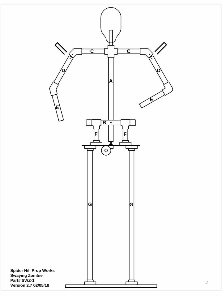
G G
F F
C C
D D
E
E
A
B
Spider Hill Prop Works
Swaying Zombie
Part# SWZ-1
Version 2.7 02/05/18
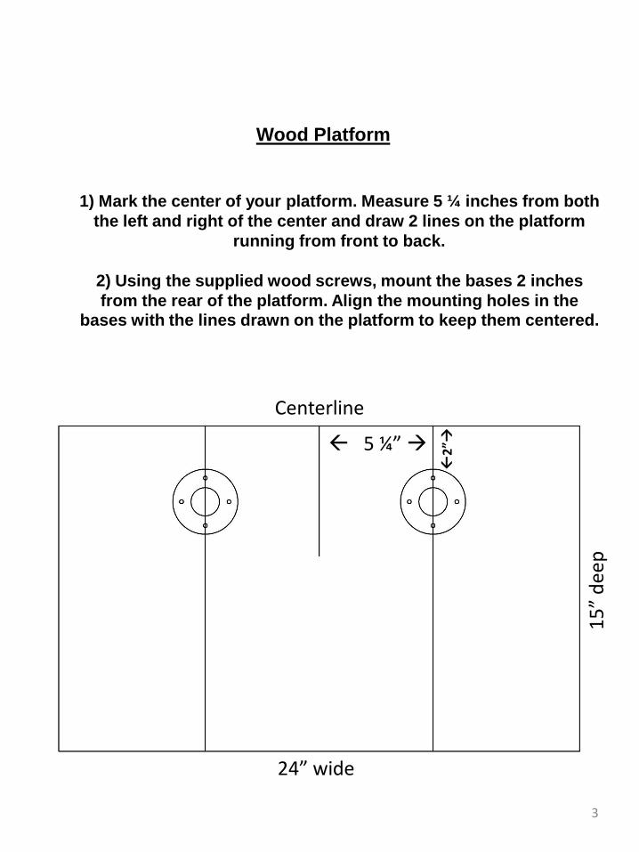
Wood Platform
1) Mark the center of your platform. Measure 5 ¼ inches from both
the left and right of the center and draw 2 lines on the platform
running from front to back.
2) Using the supplied wood screws, mount the bases 2 inches
from the rear of the platform. Align the mounting holes in the bases with the lines drawn on the platform to keep them centered.
3
24” wide
15
” d
eep
5 ¼”
Centerline
2”
4
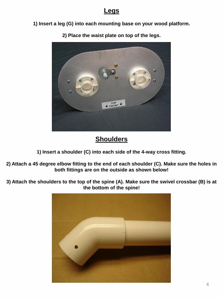
Legs
1) Insert a leg (G) into each mounting base on your wood platform.
2) Place the waist plate on top of the legs.
Shoulders
1) Insert a shoulder (C) into each side of the 4-way cross fitting.
2) Attach a 45 degree elbow fitting to the end of each shoulder (C). Make sure the holes in
both fittings are on the outside as shown below!
3) Attach the shoulders to the top of the spine (A). Make sure the swivel crossbar (B) is at
the bottom of the spine!
5
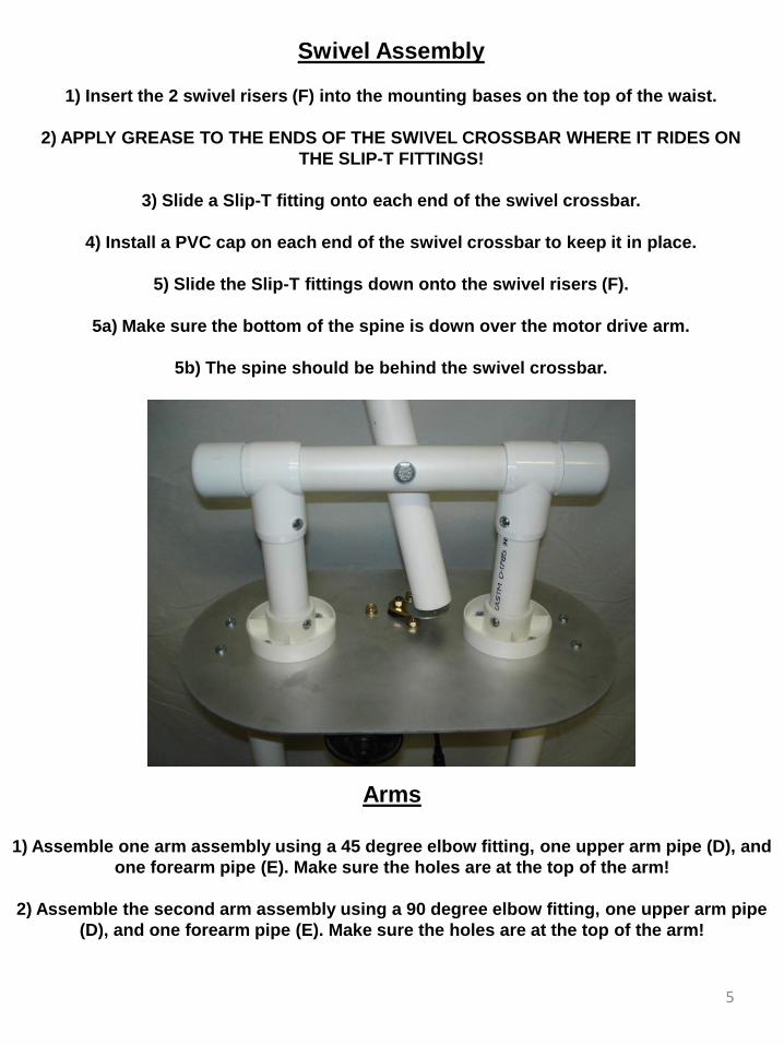
Swivel Assembly
1) Insert the 2 swivel risers (F) into the mounting bases on the top of the waist.
2) APPLY GREASE TO THE ENDS OF THE SWIVEL CROSSBAR WHERE IT RIDES ON
THE SLIP-T FITTINGS!
3) Slide a Slip-T fitting onto each end of the swivel crossbar.
4) Install a PVC cap on each end of the swivel crossbar to keep it in place.
5) Slide the Slip-T fittings down onto the swivel risers (F).
5a) Make sure the bottom of the spine is down over the motor drive arm.
5b) The spine should be behind the swivel crossbar.
Arms
1) Assemble one arm assembly using a 45 degree elbow fitting, one upper arm pipe (D), and
one forearm pipe (E). Make sure the holes are at the top of the arm!
2) Assemble the second arm assembly using a 90 degree elbow fitting, one upper arm pipe
(D), and one forearm pipe (E). Make sure the holes are at the top of the arm!
6
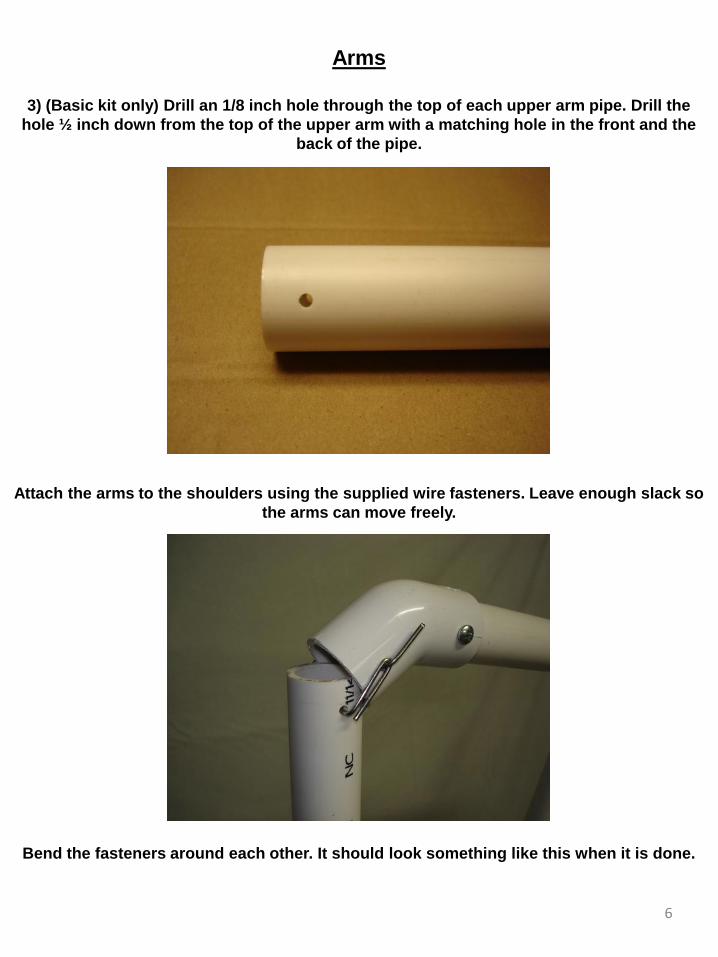
Arms
3) (Basic kit only) Drill an 1/8 inch hole through the top of each upper arm pipe. Drill the
hole ½ inch down from the top of the upper arm with a matching hole in the front and the
back of the pipe.
Attach the arms to the shoulders using the supplied wire fasteners. Leave enough slack so
the arms can move freely.
Bend the fasteners around each other. It should look something like this when it is done.
7
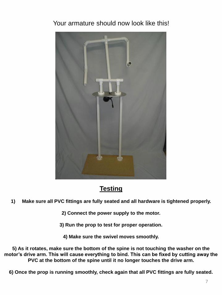
Your armature should now look like this!
Testing
1) Make sure all PVC fittings are fully seated and all hardware is tightened properly.
2) Connect the power supply to the motor.
3) Run the prop to test for proper operation.
4) Make sure the swivel moves smoothly.
5) As it rotates, make sure the bottom of the spine is not touching the washer on the
motor’s drive arm. This will cause everything to bind. This can be fixed by cutting away the
PVC at the bottom of the spine until it no longer touches the drive arm.
6) Once the prop is running smoothly, check again that all PVC fittings are fully seated.
8
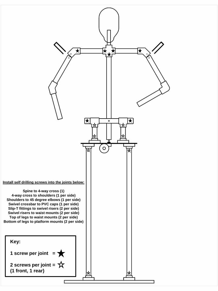
Key:
1 screw per joint =
2 screws per joint =
(1 front, 1 rear)
Install self drilling screws into the joints below:
Spine to 4-way cross (1)
4-way cross to shoulders (1 per side)
Shoulders to 45 degree elbows (1 per side)
Swivel crossbar to PVC caps (1 per side)
Slip-T fittings to swivel risers (2 per side)
Swivel risers to waist mounts (2 per side)
Top of legs to waist mounts (2 per side)
Bottom of legs to platform mounts (2 per side)
Tips:
Pool noodles, bubble wrap, or foam can be used to bulk up arms and legs.
The torso can be shaped from foam or metal hardware cloth (with ¼” squares).
We recommend using pants with a waist size of 38 inches and a 34 inch inseam.
A long sleeved shirt can be placed on first before your outer garment to prevent it from
twisting or bunching up. We typically pin the undershirt to the waistband of the pants.
Cut out the heels and soles of your shoes to fit down over the bases. Then use a screw
down through the shoe into the platform to keep the shoe in place.
If you are going to leave this prop out in the weather make sure you take steps to protect
the motor and power supply from moisture.
Squeaks or groans can typically be silenced by using some silicone grease or spray. We do
not recommend using petroleum based lubricants.
9
10
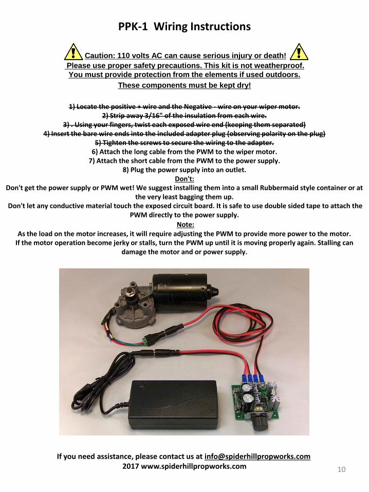
PPK-1 Wiring Instructions
Caution: 110 volts AC can cause serious injury or death! Please use proper safety precautions. This kit is not weatherproof.
You must provide protection from the elements if used outdoors.
These components must be kept dry!
1) Locate the positive + wire and the Negative - wire on your wiper motor. 2) Strip away 3/16" of the insulation from each wire.
3) . Using your fingers, twist each exposed wire end (keeping them separated) 4) Insert the bare wire ends into the included adapter plug (observing polarity on the plug)
5) Tighten the screws to secure the wiring to the adapter. 6) Attach the long cable from the PWM to the wiper motor.
7) Attach the short cable from the PWM to the power supply. 8) Plug the power supply into an outlet.
Don't: Don't get the power supply or PWM wet! We suggest installing them into a small Rubbermaid style container or at
the very least bagging them up. Don't let any conductive material touch the exposed circuit board. It is safe to use double sided tape to attach the
PWM directly to the power supply.
Note: As the load on the motor increases, it will require adjusting the PWM to provide more power to the motor.
If the motor operation become jerky or stalls, turn the PWM up until it is moving properly again. Stalling can damage the motor and or power supply.
If you need assistance, please contact us at [email protected] 2017 www.spiderhillpropworks.com