spice to qucsstudio via qucs: an international project to develop
TRANSCRIPT
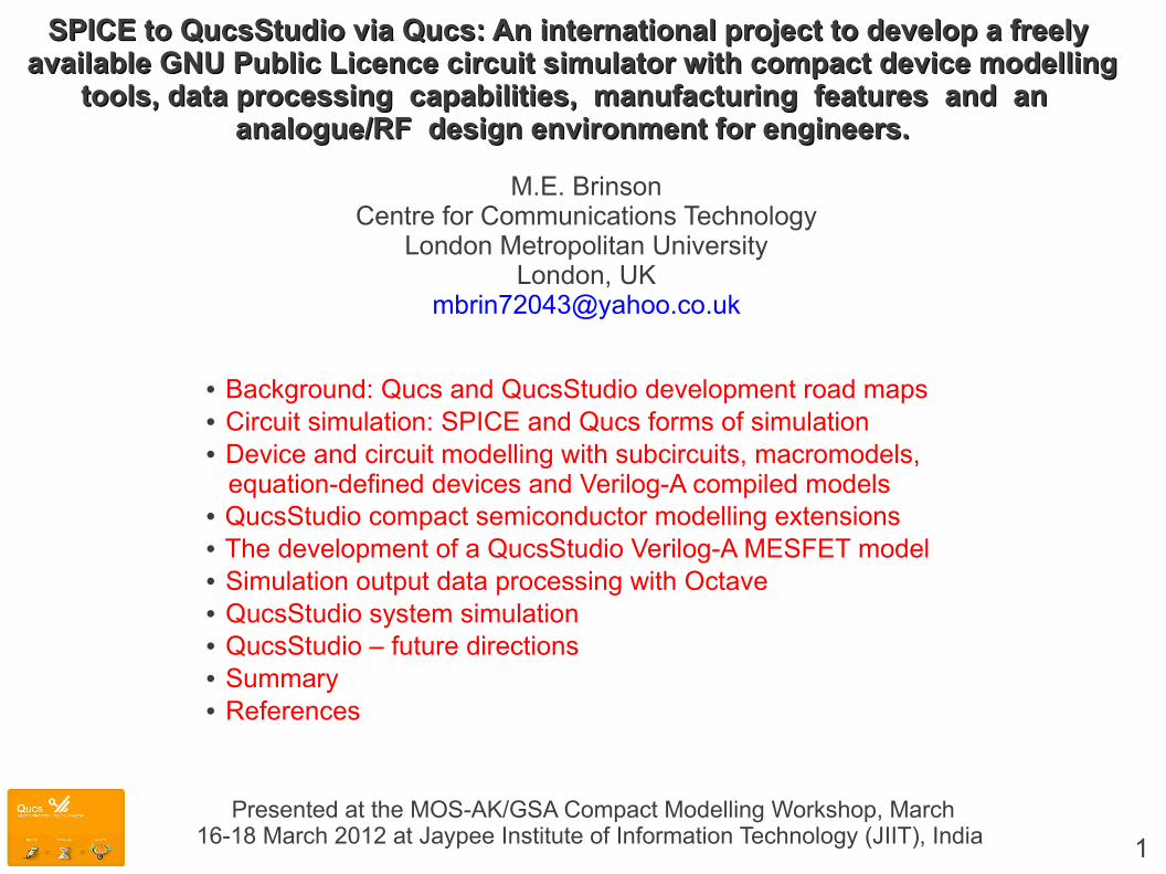
SPICE to QucsStudio via Qucs: An international project to develop a freely SPICE to QucsStudio via Qucs: An international project to develop a freely available GNU Public Licence circuit simulator with compact device modellingavailable GNU Public Licence circuit simulator with compact device modelling
tools, data processing capabilities, manufacturing features and an tools, data processing capabilities, manufacturing features and an analogue/RF design environment for engineers.analogue/RF design environment for engineers.
M.E. BrinsonCentre for Communications Technology
London Metropolitan UniversityLondon, UK
• Background: Qucs and QucsStudio development road maps• Circuit simulation: SPICE and Qucs forms of simulation• Device and circuit modelling with subcircuits, macromodels, equation-defined devices and Verilog-A compiled models• QucsStudio compact semiconductor modelling extensions• The development of a QucsStudio Verilog-A MESFET model• Simulation output data processing with Octave• QucsStudio system simulation• QucsStudio – future directions• Summary• References
Presented at the MOS-AK/GSA Compact Modelling Workshop, March16-18 March 2012 at Jaypee Institute of Information Technology (JIIT), India 1

Background: Qucs development road map
Date Release Notes [Highlights]
Dec. 2003 0.0.1 First public version of simulator - very basic.Jun. 2004 0.0.2 First MacOS version.Sep. 2004 0.0.3 Implemented S-parameters and noise analysis. Added microstrip components and
BJT and MOSFET devices.Mar. 2005 0.0.5 Implemented AC analysis and basic transient analysis.May 2005 0.0.6 Mainly bug fixes and extensions to implemented analysis.Jul. 2005 0.0.7 Windows 32 version. Simulator renamed as Qucs. New device library manager.
Added post simulation data processing mathematical functions.Jan. 2006 0.0.8 Support for pure digital simulation using FreeHDL. Added many new component
models. Improved post simulation data plotting features. Added a filter synthesis tool.May 2006 0.0.9 New functions in equation solver. Harmonic Balance simulation introduced. Many
new components added.Sept. 2006 0.0.10 Qucs converter tool improved. Support for nine-valued VHDL logic. Circuit optimization
introduced using ASCO. Added attenuator design tool.Mar. 2007 0.0.11 Added device parameters to equations and parameters to subcircuits. New models plus
improvements to existing models. Using ADMS to translate Verilog-A device models foruse in Qucs.
Jun. 2007 0.0.12 Lots of new components, bug fixes and small improvements. Added support for Verilog using Icarus Verilog. Support for symbolically equation-defined devices (EDD). Explicit equations allowed.
Nov. 2007 0.0.13 General improvements plus implementation of immediate vectors and matrices in equations.Apr. 2008 0.0.14 Implemented multi-port equation-defined RF device (RFEDD) S, Y and Z parameters
available. Two-port equation-defined device also supported.Apr. 2009 0.0.15 Mainly bug fixes, small improvements and the addition of new models.Mar. 2011 0.0.16 Implemented interactive post simulation data processing using Octave. Again many bug
fixes, small improvements and the addition of new models.
2
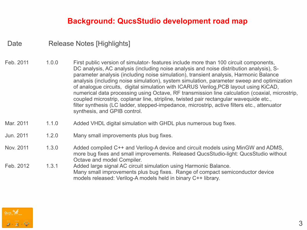
Background: QucsStudio development road map
Date Release Notes [Highlights]
Feb. 2011 1.0.0 First public version of simulator- features include more than 100 circuit components, DC analysis, AC analysis (including noise analysis and noise distribution analysis), S-parameter analysis (including noise simulation), transient analysis, Harmonic Balanceanalysis (including noise simulation), system simulation, parameter sweep and optimizationof analogue circuits, digital simulation with ICARUS Verilog,PCB layout using KiCAD, numerical data processing using Octave, RF transmission line calculation (coaxial, microstrip,coupled microstrip, coplanar line, stripline, twisted pair rectangular wavequide etc., filter synthesis (LC ladder, stepped-impedance, microstrip, active filters etc., attenuator synthesis, and GPIB control.
Mar. 2011 1.1.0 Added VHDL digital simulation with GHDL plus numerous bug fixes.
Jun. 2011 1.2.0 Many small improvements plus bug fixes.
Nov. 2011 1.3.0 Added compiled C++ and Verilog-A device and circuit models using MinGW and ADMS, more bug fixes and small improvements. Released QucsStudio-light: QucsStudio without Octave and model Compiler.
Feb. 2012 1.3.1 Added large signal AC circuit simulation using Harmonic Balance.Many small improvements plus bug fixes. Range of compact semiconductor devicemodels released: Verilog-A models held in binary C++ library.
3

SPICE and Qucs basic types of simulation facilities
4
DC
AC
TRAN
S-parameter*
*Implementation 1. Qucs: built-in; 2. SPICE: via RCL networks
Circuitencoding
SPICE 2g6 and 3f5NETLIST
QucsSchematic diagram
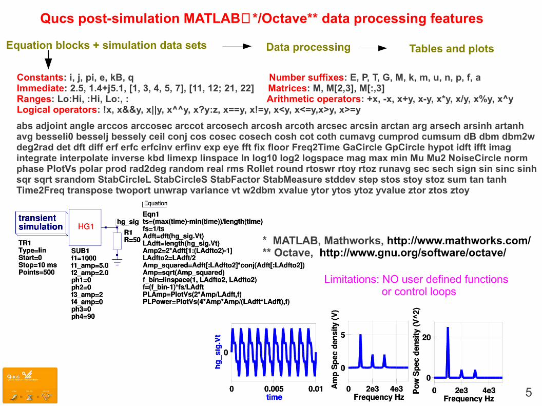
Qucs post-simulation MATLAB*/Octave** data processing features
Constants: i, j, pi, e, kB, q Number suffixes: E, P, T, G, M, k, m, u, n, p, f, aImmediate: 2.5, 1.4+j5.1, [1, 3, 4, 5, 7], [11, 12; 21, 22] Matrices: M, M[2,3], M[:,3]Ranges: Lo:Hi, :Hi, Lo:, : Arithmetic operators: +x, -x, x+y, x-y, x*y, x/y, x%y, x^yLogical operators: !x, x&&y, x||y, x^^y, x?y:z, x==y, x!=y, x<y, x<=y,x>y, x>=y
Equation blocks + simulation data sets
abs adjoint angle arccos arccosec arccot arcosech arcosh arcoth arcsec arcsin arctan arg arsech arsinh artanh avg besseli0 besselj bessely ceil conj cos cosec cosech cosh cot coth cumavg cumprod cumsum dB dbm dbm2w deg2rad det dft diff erf erfc erfcinv erfinv exp eye fft fix floor Freq2Time GaCircle GpCircle hypot idft ifft imag integrate interpolate inverse kbd limexp linspace ln log10 log2 logspace mag max min Mu Mu2 NoiseCircle norm phase PlotVs polar prod rad2deg random real rms Rollet round rtoswr rtoy rtoz runavg sec sech sign sin sinc sinh sqr sqrt srandom StabCircleL StabCircleS StabFactor StabMeasure stddev step stos stoy stoz sum tan tanh Time2Freq transpose twoport unwrap variance vt w2dbm xvalue ytor ytos ytoz yvalue ztor ztos ztoy
* MATLAB, Mathworks, http://www.mathworks.com/ ** Octave, http://www.gnu.org/software/octave/
5
Data processing Tables and plots
Limitations: NO user defined functions or control loops
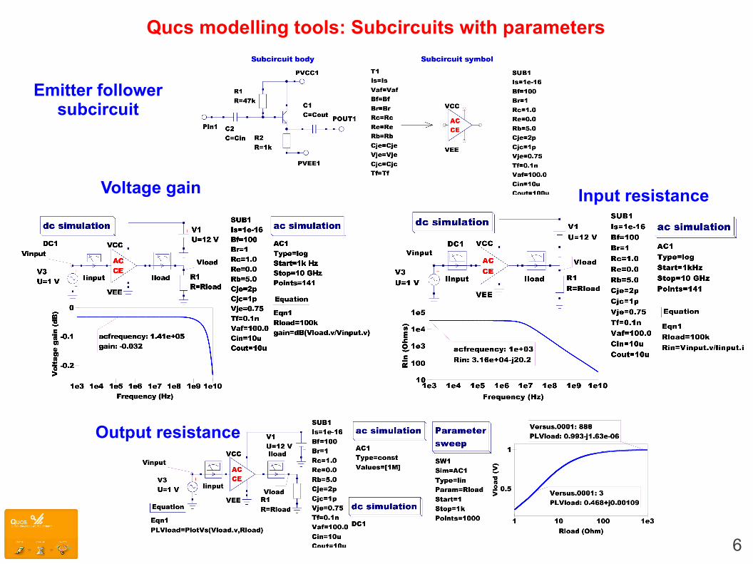
Qucs modelling tools: Subcircuits with parameters
6
Emitter followersubcircuit
Voltage gain Input resistance
Output resistance
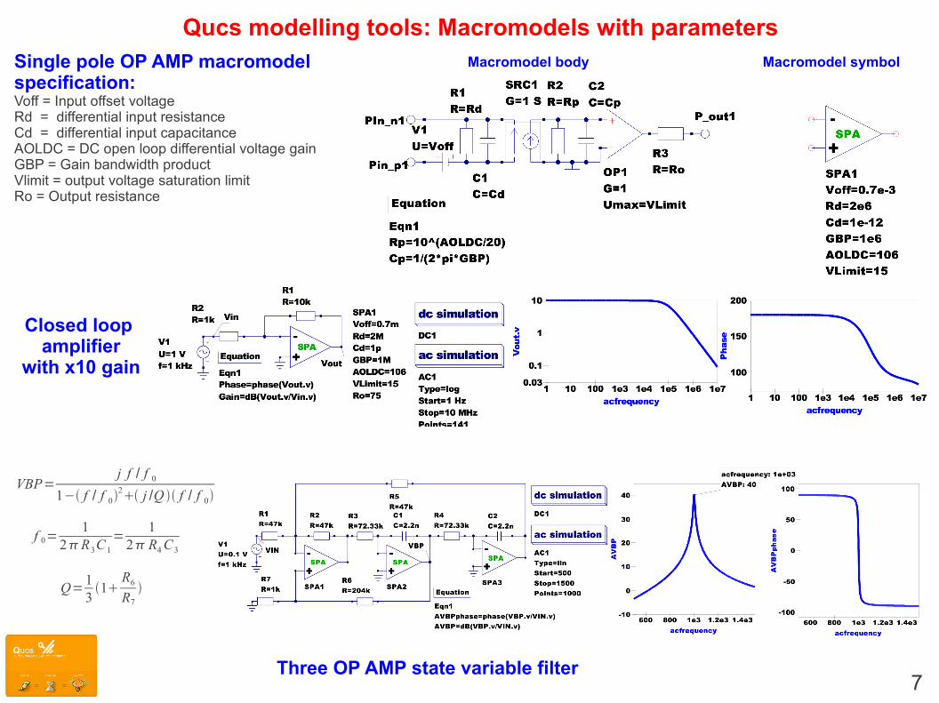
Qucs modelling tools: Macromodels with parameters
7
Single pole OP AMP macromodel specification:Voff = Input offset voltageRd = differential input resistanceCd = differential input capacitanceAOLDC = DC open loop differential voltage gainGBP = Gain bandwidth productVlimit = output voltage saturation limitRo = Output resistance
Closed loop amplifier
with x10 gain
Macromodel body Macromodel symbol
Three OP AMP state variable filter
VBP=j f / f 0
1− f / f 02 j /Q f / f 0
f 0=1
2R3C1
=1
2 R4C3
Q=131
R6
R7

8
Qucs modelling tools: Equation-defined device (EDD) modelling
Relationships between Qucs schematic symbols and Verilog-Acode fragments
Fundamental EDD blocks
9
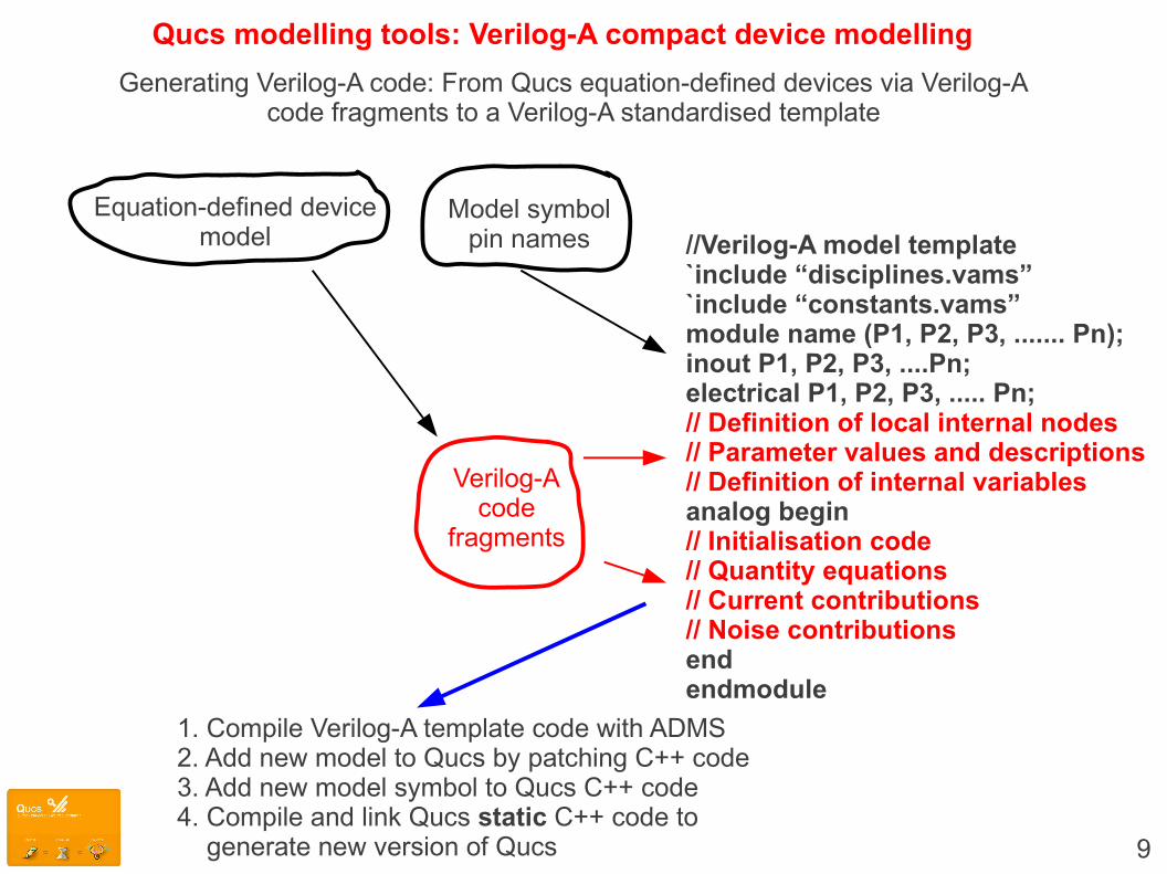
Qucs modelling tools: Verilog-A compact device modelling
Generating Verilog-A code: From Qucs equation-defined devices via Verilog-Acode fragments to a Verilog-A standardised template
//Verilog-A model template`include “disciplines.vams”`include “constants.vams”module name (P1, P2, P3, ....... Pn);inout P1, P2, P3, ....Pn;electrical P1, P2, P3, ..... Pn;// Definition of local internal nodes// Parameter values and descriptions// Definition of internal variablesanalog begin// Initialisation code// Quantity equations// Current contributions// Noise contributionsendendmodule
Model symbolpin names
Equation-defined devicemodel
Verilog-Acode
fragments
1. Compile Verilog-A template code with ADMS2. Add new model to Qucs by patching C++ code3. Add new model symbol to Qucs C++ code4. Compile and link Qucs static C++ code to generate new version of Qucs
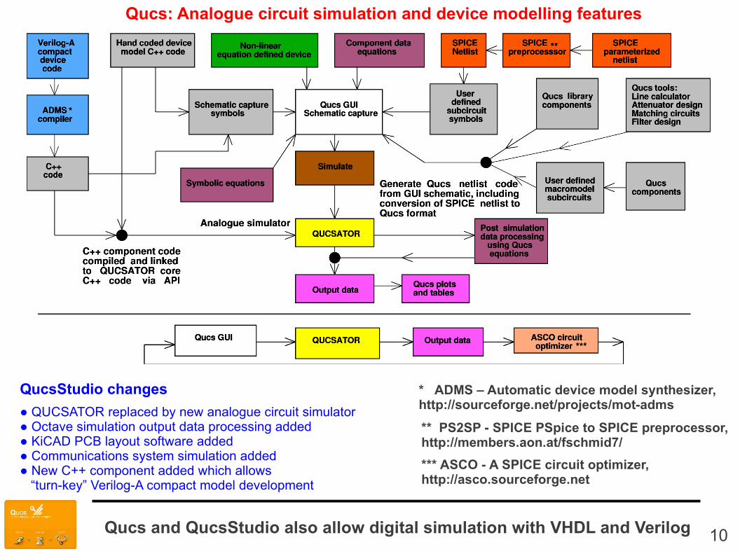
Qucs: Analogue circuit simulation and device modelling features
* ADMS – Automatic device model synthesizer, http://sourceforge.net/projects/mot-adms
*** ASCO - A SPICE circuit optimizer, http://asco.sourceforge.net
** PS2SP - SPICE PSpice to SPICE preprocessor, http://members.aon.at/fschmid7/
10
QucsStudio changes
● QUCSATOR replaced by new analogue circuit simulator● Octave simulation output data processing added● KiCAD PCB layout software added● Communications system simulation added● New C++ component added which allows “turn-key” Verilog-A compact model development
Qucs and QucsStudio also allow digital simulation with VHDL and Verilog

11
QucsStudio: Compact semiconductor device and circuit macromodel construction using ADMS and MinGW
dynamically linked models
CompactSemiconductorDevice or circuit
macromodels
CompactSemiconductorDevice or circuit
macromodels
CompactSemiconductordevice or circuit
physicalequations
Equation-defineddevice model
or circuit macromodel
Verilog-Afragments
Verilog-Amodelcode
[Templatestructure]
C++ Compiled model
C++
Pin1
::
Pinn
Pout1
Poutn
Symbol
Pin1
::
Pinn
Pout1
Poutn
Subcircuitsymbol
Generate Verilog-A codewith the QucsStudio
colour highlighted text editor
File XXX.va
File XXX.va.cpp
File XXX.dll
“Turn-Key” Verilog-A compact model development system WHERE the Verilog-Acode is automatically recompiled ONLY if it has been changed prior to the start of a simulation
Other QucsStudio components may be included in asubcircuit with one or more compiled C++ models
Subcircuit body API functions for C++
component creation
ADMSMinGW tools
Attach

12
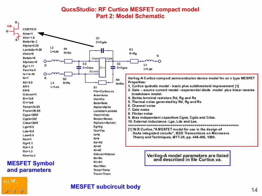
QucsStudio: RF Curtice MESFET compact modelPart 1: Verilog-A code
// Verilog-A Curtice MESFET: hyperbolic tangent model// with fixed capacitance and noise ; Curtice.va.// This is free software; you can redistribute it and/or modify// it under the terms of the GNU General Public License as published by// the Free Software Foundation; either version 2, or (at your option)// any later version.// // Copyright (C), Mike Brinson, [email protected] // QucsStudio version September 2011.//`include "disciplines.vams"`include "constants.vams"//module Curtice(Drain, Gate, Source); inout Drain, Gate, Source;electrical Drain, Gate, Source;//`define attr(txt) (*txt*) `define CTOK 273.15`define K1 7.02e-4`define K2 1108.0`define K3 400e-6`define GMIN 1e-12
//parameter real Area = 1 from (1 : inf) `attr(info="area factor" );parameter real Vto = -1.8 from (-inf : inf) `attr(info="pinch-off voltage" unit = "V");parameter real Beta = 3e-3 from [1e-9 : inf) `attr(info="transconductance parameter" unit = "A/(V*V)");parameter real Alpha = 2.25 from [1e-9 : inf) `attr(info="saturation voltage parameter" unit="1/V" );parameter real Lambda = 0.05 from [1e-9 :inf) `attr(info="channel length modulation parameter" unit="1/V");parameter real Vtotc = 0 from (-inf : inf) `attr(info="Vto temperature coefficient");parameter real Betatc = 0 from (-inf : inf) `attr(info="Beta temperature coefficient" unit = "%/Celsius");parameter real Alphatc = 0 from (-inf : inf] `attr(info="Alpha temperature coefficient" unit = "%/Celsius");parameter real Eg = 1.11 from [1e-6 : inf) `attr(info="energy gap" unit = "eV");parameter real Tau = 1e-9 from [1e-20 : inf) `attr(info="transit time under gate" unit = "s");parameter real Is = 1e-14 from [1e-20 : inf) `attr(info="diode saturation current" unit = "I");parameter real N = 1 from [1e-9 : inf) `attr(info="diode emission coefficient");parameter real Xti = 3.0 from [1e-9 : inf) `attr(info="diode saturation current temperature coefficient");parameter real Af = 1 from [0 : inf) `attr(info="flicker noise exponent");parameter real Kf = 0 from [0 : inf) `attr(info="flicker noise coefficient");parameter real Gdsnoi = 1 from [0 : inf) `attr(info="shot noise coefficient");parameter real Bv = 1e9 from (-inf : inf) `attr(info="drain-gate junction reverse bias breakdown voltage" unit = "V" );parameter real R1 = 1e9 from [1e-9 : inf) `attr(info="breakdown slope resistance" unit = "Ohms");parameter real Nsc = 1 from [1e-9 : inf) `attr(info="subthreshold conductance parameter");parameter real Temp = 26.85 from [-273 : inf) `attr(info="circuit temperature" unit = "Celsius");parameter real Tnom = 26.85 from [-273 : inf) `attr(info="parameter measurement temperature" unit = "Celsius");
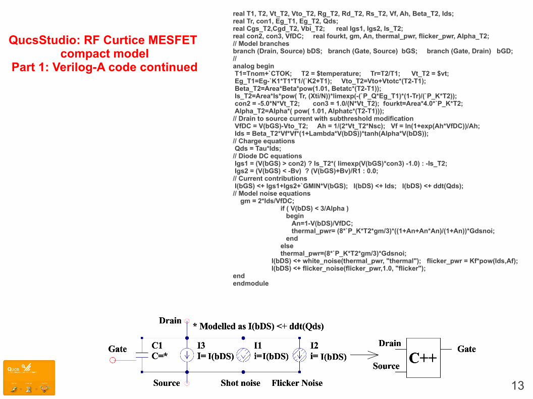
13
QucsStudio: RF Curtice MESFET compact model
Part 1: Verilog-A code continued
real T1, T2, Vt_T2, Vto_T2, Rg_T2, Rd_T2, Rs_T2, Vf, Ah, Beta_T2, Ids;real Tr, con1, Eg_T1, Eg_T2, Qds;real Cgs_T2,Cgd_T2, Vbi_T2; real Igs1, Igs2, Is_T2;real con2, con3, VfDC; real fourkt, gm, An, thermal_pwr, flicker_pwr, Alpha_T2;// Model branchesbranch (Drain, Source) bDS; branch (Gate, Source) bGS; branch (Gate, Drain) bGD;//analog begin T1=Tnom+`CTOK; T2 = $temperature; Tr=T2/T1; Vt_T2 = $vt; Eg_T1=Eg-`K1*T1*T1/(`K2+T1); Vto_T2=Vto+Vtotc*(T2-T1); Beta_T2=Area*Beta*pow(1.01, Betatc*(T2-T1)); Is_T2=Area*Is*pow( Tr, (Xti/N))*limexp(-(`P_Q*Eg_T1)*(1-Tr)/(`P_K*T2)); con2 = -5.0*N*Vt_T2; con3 = 1.0/(N*Vt_T2); fourkt=Area*4.0*`P_K*T2; Alpha_T2=Alpha*( pow( 1.01, Alphatc*(T2-T1)));// Drain to source current with subthreshold modification VfDC = V(bGS)-Vto_T2; Ah = 1/(2*Vt_T2*Nsc); Vf = ln(1+exp(Ah*VfDC))/Ah; Ids = Beta_T2*Vf*Vf*(1+Lambda*V(bDS))*tanh(Alpha*V(bDS));// Charge equations Qds = Tau*Ids;// Diode DC equations Igs1 = (V(bGS) > con2) ? Is_T2*( limexp(V(bGS)*con3) -1.0) : -Is_T2; Igs2 = (V(bGS) < -Bv) ? (V(bGS)+Bv)/R1 : 0.0; // Current contributions I(bGS) <+ Igs1+Igs2+`GMIN*V(bGS); I(bDS) <+ Ids; I(bDS) <+ ddt(Qds);// Model noise equations gm = 2*Ids/VfDC;
if ( V(bDS) < 3/Alpha ) begin An=1-V(bDS)/VfDC; thermal_pwr= (8*`P_K*T2*gm/3)*((1+An+An*An)/(1+An))*Gdsnoi; endelsethermal_pwr=(8*`P_K*T2*gm/3)*Gdsnoi;
I(bDS) <+ white_noise(thermal_pwr, "thermal"); flicker_pwr = Kf*pow(Ids,Af); I(bDS) <+ flicker_noise(flicker_pwr,1.0, "flicker");
endendmodule
14
QucsStudio: RF Curtice MESFET compact modelPart 2: Model Schematic
MESFET subcircuit body
MESFET Symboland parameters
15
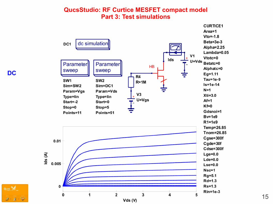
QucsStudio: RF Curtice MESFET compact modelPart 3: Test simulations
DC

QucsStudio: RF Curtice MESFET compact modelPart 3: Test simulations
16
AC
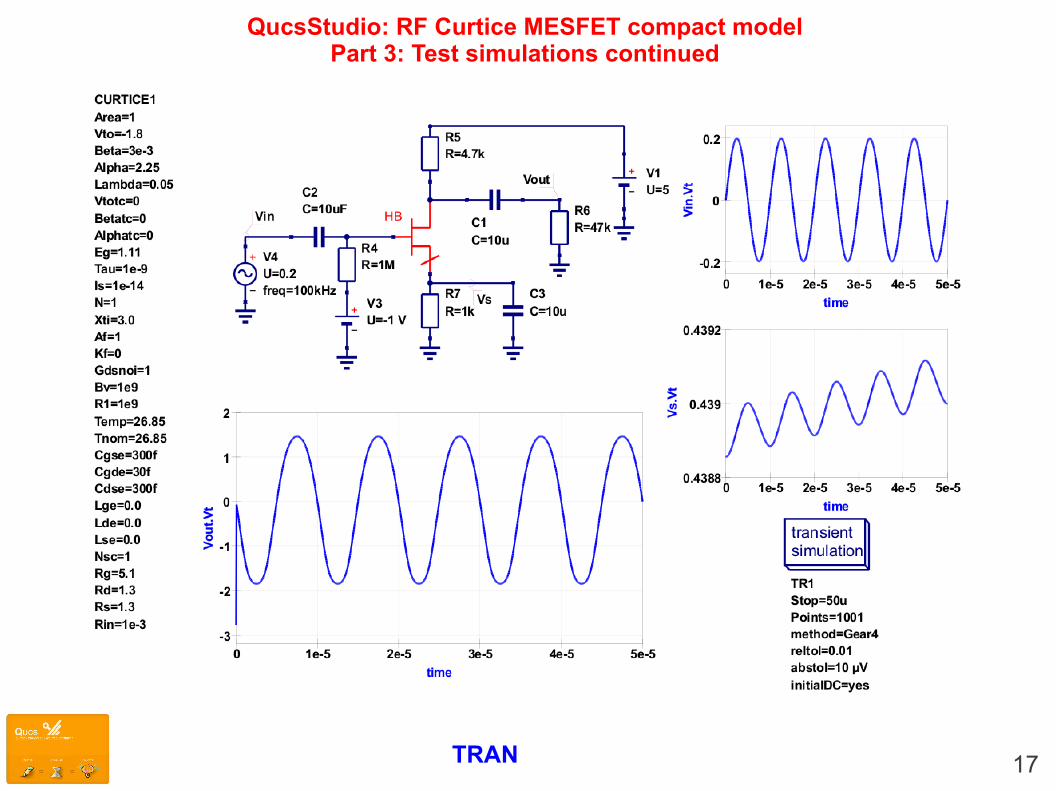
QucsStudio: RF Curtice MESFET compact modelPart 3: Test simulations continued
TRAN 17
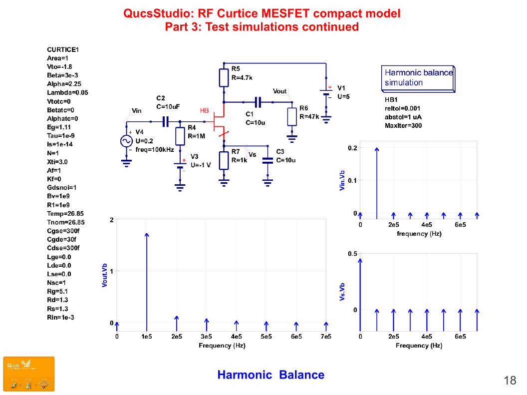
QucsStudio: RF Curtice MESFET compact modelPart 3: Test simulations continued
Harmonic Balance 18
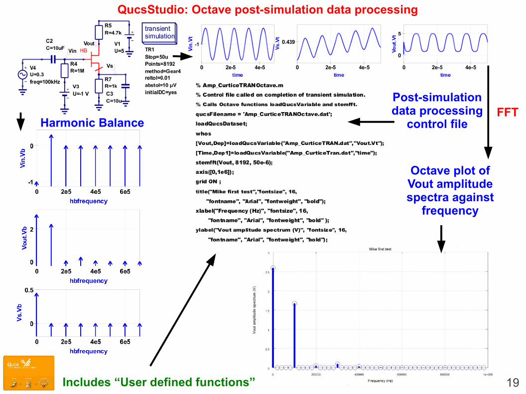
QucsStudio: Octave post-simulation data processing
Post-simulationdata processing
control file
Octave plot ofVout amplitudespectra against
frequency
Harmonic BalanceFFT
Includes “User defined functions” 19
20
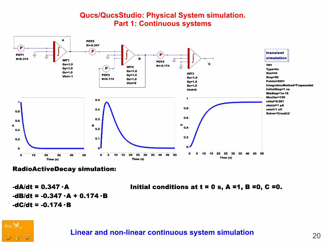
Qucs/QucsStudio: Physical System simulation.Part 1: Continuous systems
Linear and non-linear continuous system simulation
21
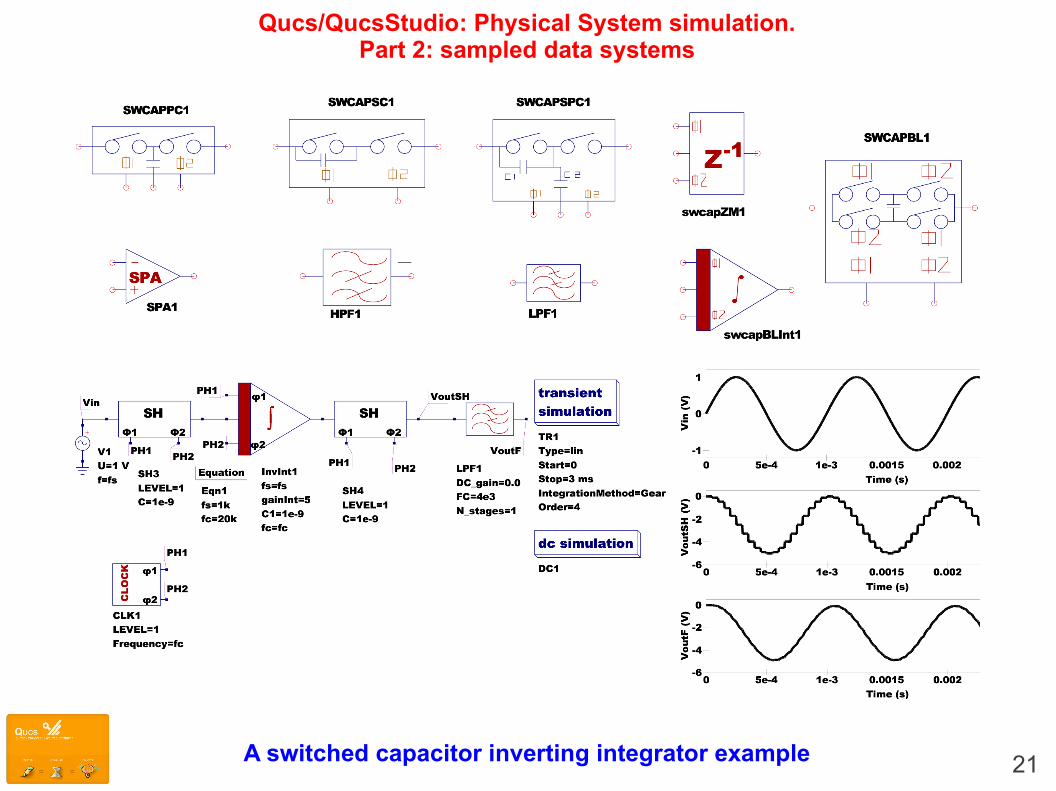
Qucs/QucsStudio: Physical System simulation.Part 2: sampled data systems
A switched capacitor inverting integrator example
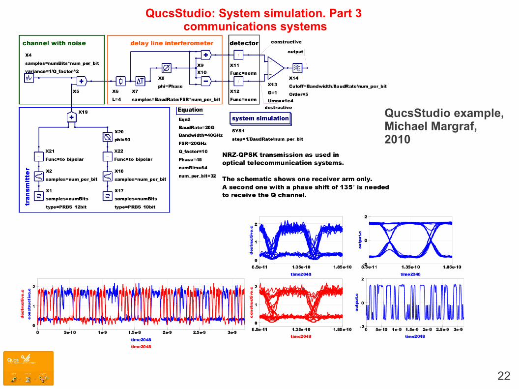
QucsStudio: System simulation. Part 3 communications systems
22
QucsStudio example,Michael Margraf,2010
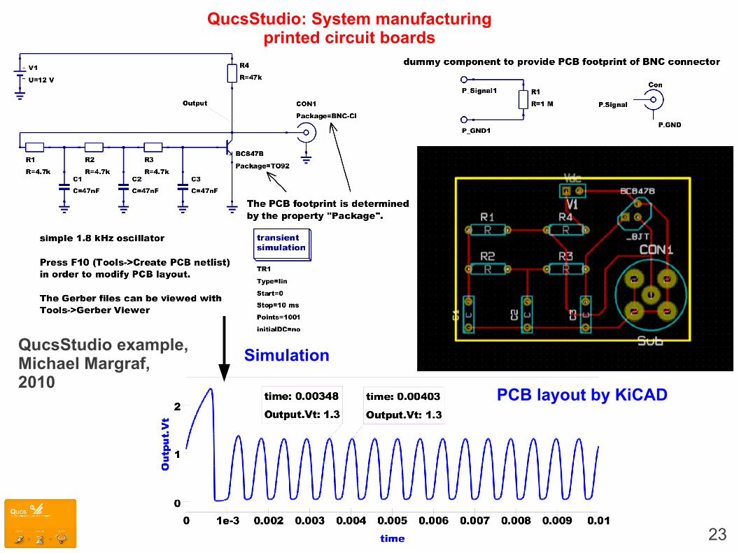
23
QucsStudio: System manufacturing printed circuit boards
QucsStudio example,Michael Margraf,2010
PCB layout by KiCAD
Simulation
24
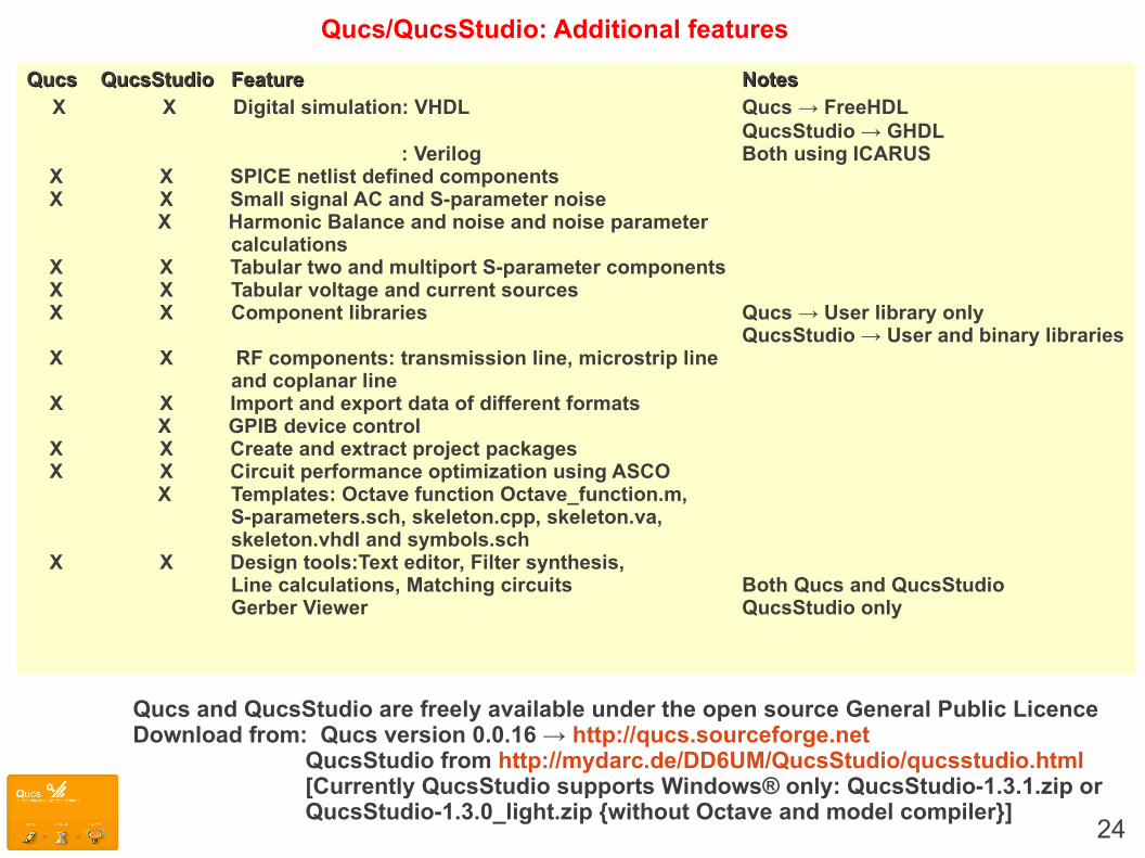
Qucs/QucsStudio: Additional features
QucsQucs QucsStudio QucsStudio FeatureFeature NotesNotes X X Digital simulation: VHDL Qucs → FreeHDL
QucsStudio → GHDL : Verilog Both using ICARUS
X X SPICE netlist defined components X X Small signal AC and S-parameter noise X Harmonic Balance and noise and noise parameter
calculations X X Tabular two and multiport S-parameter components X X Tabular voltage and current sources X X Component libraries Qucs → User library only
QucsStudio → User and binary libraries X X RF components: transmission line, microstrip line
and coplanar line X X Import and export data of different formats X GPIB device control X X Create and extract project packages X X Circuit performance optimization using ASCO X Templates: Octave function Octave_function.m,
S-parameters.sch, skeleton.cpp, skeleton.va,skeleton.vhdl and symbols.sch
X X Design tools:Text editor, Filter synthesis, Line calculations, Matching circuits Both Qucs and QucsStudioGerber Viewer QucsStudio only
Qucs and QucsStudio are freely available under the open source General Public LicenceDownload from: Qucs version 0.0.16 → http://qucs.sourceforge.net
QucsStudio from http://mydarc.de/DD6UM/QucsStudio/qucsstudio.html [Currently QucsStudio supports Windows® only: QucsStudio-1.3.1.zip or QucsStudio-1.3.0_light.zip {without Octave and model compiler}]

QucsStudio: Latest additions: Large signal AC simulation
AC HB TRAN 25
RF Diode Switch Model Test circuit
26
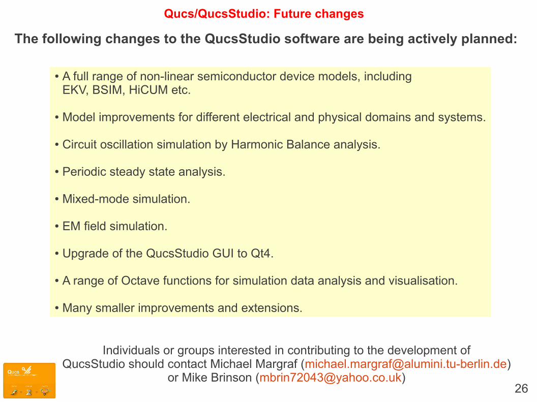
Qucs/QucsStudio: Future changes
The following changes to the QucsStudio software are being actively planned:
● A full range of non-linear semiconductor device models, including EKV, BSIM, HiCUM etc.
● Model improvements for different electrical and physical domains and systems.
● Circuit oscillation simulation by Harmonic Balance analysis.
● Periodic steady state analysis.
● Mixed-mode simulation.
● EM field simulation.
● Upgrade of the QucsStudio GUI to Qt4.
● A range of Octave functions for simulation data analysis and visualisation.
● Many smaller improvements and extensions.
Individuals or groups interested in contributing to the development ofQucsStudio should contact Michael Margraf ([email protected])
or Mike Brinson ([email protected])
27
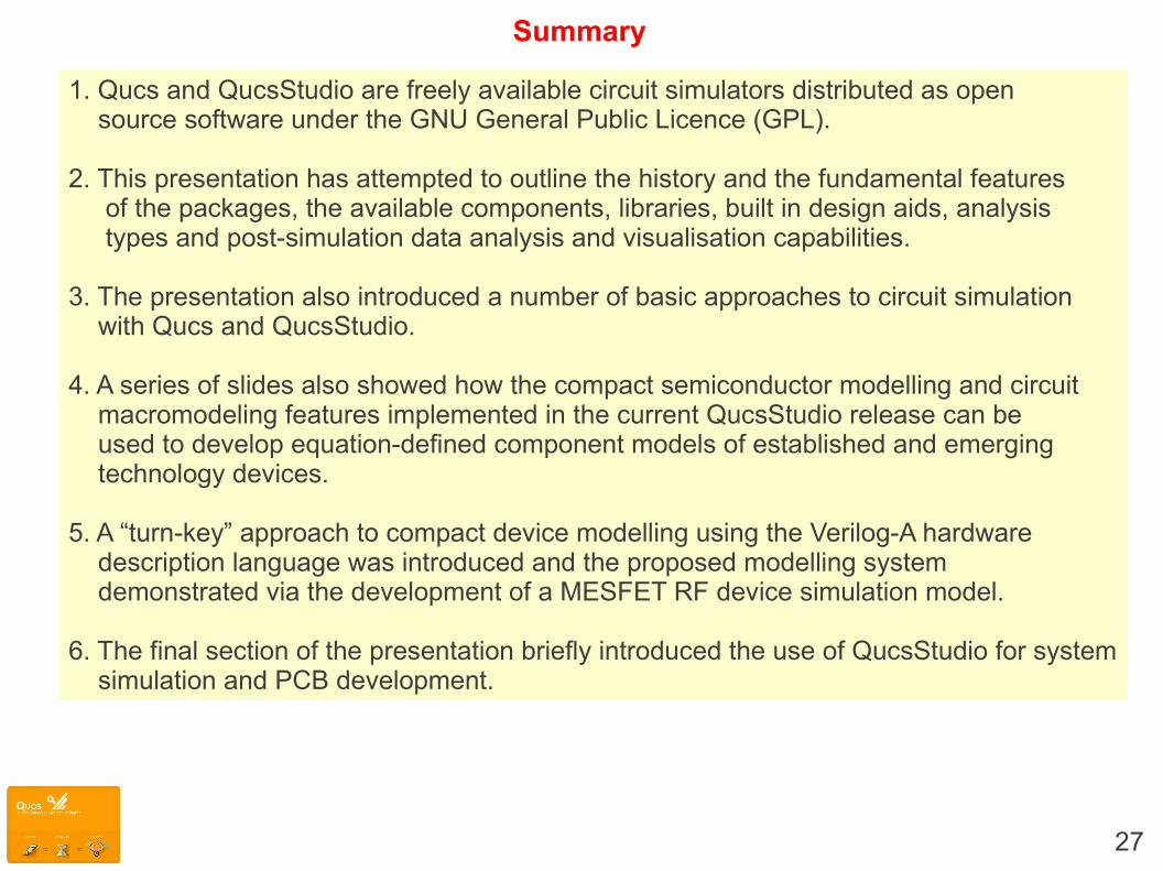
Summary
1. Qucs and QucsStudio are freely available circuit simulators distributed as open source software under the GNU General Public Licence (GPL).
2. This presentation has attempted to outline the history and the fundamental features of the packages, the available components, libraries, built in design aids, analysis types and post-simulation data analysis and visualisation capabilities.
3. The presentation also introduced a number of basic approaches to circuit simulation with Qucs and QucsStudio.
4. A series of slides also showed how the compact semiconductor modelling and circuit macromodeling features implemented in the current QucsStudio release can be used to develop equation-defined component models of established and emerging technology devices.
5. A “turn-key” approach to compact device modelling using the Verilog-A hardware description language was introduced and the proposed modelling system demonstrated via the development of a MESFET RF device simulation model.
6. The final section of the presentation briefly introduced the use of QucsStudio for system simulation and PCB development.
28
References
Brinson M. and Jahn S., Interactive compact device modelling using Qucs equation defined devices, International Journal of Numerical Modelling: Electrical Networks, Devices and Fields, 21(5) pp. 335-349, September/October 2008. DOI : 10.1002/jnm.676.
Brinson M. and Jahn S., Qucs: A GPL software package for circuit simulation, compact device modelling and circuit macromodelling from DC to RF and Beyond, International Journal of Numerical Modelling: Electrical Networks, Devices and Fields, 22(4) pp. 297-319, July/August 2009. DOI : 10.1002/jnm.702.
Brinson M. and Jahn S., Compact macromodelling of operational amplifiers with equation defined devices, International Journal of Electronics, 96(2), pp. 109-122, February 2009, DOI:10.1080/00207210802580288, ISSN : 0020-7217.
Brinson M. and Jahn S., Modelling of high-frequency inductance with Qucs non-linear radio frequency equation-defined devices, International Journal of Electronics, 96(3), March 2009, DOI:10.1080/00207210802640603, ISSN : 0020-7217.
Brinson M.E., Jahn S. and Nabijou H., Z Domain delay subcircuits and compact Verilog-A macromodels for mixed-mode sampled data circuit simulation, Test Technology Technical Council (TTTC) of the IEEE Computer Society, Radioelectronics & Informatics Journal, Vol. 45, No. 2, pp. 14-20, April/June 2009. ISSN 1563-0064.
Brinson M.E. and Nabijou H., Adaptive subcircuits and compact Verilog-A macromodels as integrated design and analysis blocks in Qucs circuit simulation,International Journal of Electronics, Vol. 98 (5), pp. 631-645, May 2011. DOI: 10.1080/00207217.2011.562452.
Brinson M.E., Jahn S. and Nabijou H., A tabular source approach to modelling and simulating device and circuit noise in the time domain, International Journal of Numerical Modelling: Electronic Networks, Devices and Fields, Vol 26(6), pp. 555-567, November/December 2011. DOI: 10.1002/jnm801.
Brinson M. and Jahn S., Compact device modelling for established and emerging technologies with the Qucs GPL circuit simulator, Mixed design of Integrated Circuits and Systems (MIXDES) 2009, Proceedings of the 16 International Conference, pp. 39-44, Lodz, Poland, June 2009. ISBN 978-1-4244-4798-5. INSPEC Accession Number: 10928855. Available from: http://ieeexplore.ieee.org/xpl/freeabs_all.jsp?arnumber=5289598.
Brinson M.E., Jahn S. and Nabijou H., A hybrid Verilog-A and equation-defined subcircuit approach to MOS switched current analog cell modeling and simulation in the transient and large signal AC domains, Mixed design of Integrated Circuits and Systems (MIXDES) 2010, Proceedings of the 17 International Conference, pp. 3-48, Wroclaw,Poland, June 2010.ISBN 978-1-4244-7011-2, INSPEC Accession Number: 11487844. Available from:http://ieeexplore.ieee.org/xpl/freeabs_all.jsp?arnumber=5551306
Brinson M.E., Jahn S. and Nabijou H., Adaptive EPFL-EKV long and short channel MOS device models for Qucs, SPICE and Modelica circuit simulation, Mixed design of Integrated Circuits and Systems (MIXDES) 2011, Proceedings of the 18 International Conference, pp. 65-70, Gliwice, Poland, June 2011.ISBN 978-1-4577-0304-1. INSPEC Accession Number: 12219696. Available from:http://ieeexplore.ieee.org/xpl/freeabs_all.jsp?arnumber=6016035
Jahn S., Brinson M.E., Margraf M., Parruitte H., Ardouin B., Nenzi P., and Lemaitre L., GNU simulators supporting Verilog-A compact model standardization, MOS-AK International Meeting, Premstaetten, Germany, March 2007. Available from:http://www.mos-ak.org/premstaetten/papers/MOS-AK_QUCS_ngspice_ADMS.pdf
Brinson M. and Jahn S., Building device models and circuit macromodels with the Qucs GPL simulator : A demonstration, Presentation to the European Network on Compact Modelling (COMON), Frankfurt(O), Germany, 2 April 2009. Available from: http://www.mos-ak.org/frankfurt_o/papers/M_Brinson_Qucs_COMON_April_2_2009_final.pdf
Brinson M., Jahn S. and Cullinan M., Advances in compact semiconductor device modelling and circuit macromodelling with the Qucs GPL circuit simulator, MOS-AKInternational Meeting, Frankfurt(O), Germany, 3 April 2009. Available from: http://www.mos-ak.org/frankfurt_o/papers/P_7_Brinson_MOS-AK_April_2009_final.pdf
Brinson M.E., Jahn S. and Nabijou H., Qucs, SPICE and Modelica equation-defined modelling techniques for the construction of compact device models based on a common model template structure, MOS-AK/GSA International workshop on the frontiers of compact modeling for advanced analog/RF applications, Université Pierre et Marie Curie, Paris, April 2011. Available from: http://www.mos-ak.org/paris/papers/P06_Brinson_MOS-AK_Paris.pdf
NEW BOOK: Open Source/GNU CAD for Compact Modelling, Editors: Wladek Grabinski and DanielTomaszewski. Publisher: Mark de Jongh [[email protected]], www.springer-sbm.com.Chapter 5: M.E. Brinson, Schematic entry and circuit simulation with Qucs.Chapter 6: M.E. Brinson, Qucs modelling and simulation of analogue/RF devices and circuits.