sphere assembly and operation demonstration
TRANSCRIPT

INL/EXT-20-60782
Revision 0
SPHERE Assembly and
Operation Demonstration
December 2020

DISCLAIMER
This information was prepared as an account of work sponsored by an
agency of the U.S. Government. Neither the U.S. Government nor any
agency thereof, nor any of their employees, makes any warranty, expressed
or implied, or assumes any legal liability or responsibility for the accuracy,
completeness, or usefulness, of any information, apparatus, product, or
process disclosed, or represents that its use would not infringe privately
owned rights. References herein to any specific commercial product,
process, or service by trade name, trade mark, manufacturer, or otherwise,
does not necessarily constitute or imply its endorsement, recommendation,
or favoring by the U.S. Government or any agency thereof. The views and
opinions of authors expressed herein do not necessarily state or reflect
those of the U.S. Government or any agency thereof.

INL/EXT-20-60782 Revision 0
SPHERE Assembly and Operation Demonstration
Piyush Sabharwall Jeremy Hartvigsen
Terry Morton Zach Sellers Jun Soo Yoo
December 2020
Idaho National Laboratory Originating Organization Idaho Falls, Idaho 83415
http://www.inl.gov
Prepared for the U.S. Department of Energy
Office of NE Under DOE Idaho Operations Office
Contract DE-AC07-05ID14517

Page intentionally left blank
ii
SUMMARY
The objective of the current scope was to complete single primary heat extraction and removal emulator
(SPHERE) assembly and demonstrate the operation of the SPHERE facility. The initial testing consisted of
vacuum operation of a sodium heat pipe. The temperature was measured at 10 evenly spaced points along
the heat pipe. Additional exterior thermocouple measurements were also taken on the exterior of the heat
pipe to confirm the similarity of thermowell temperatures to exterior heat pipe temperature measurements.
The initial test was successfully completed and results measured at INL are consistent with the data from
the manufacturer.

iii
Page intentionally left blank

iv
CONTENTS
1. SPHERE Assembly and Operation Demonstration ............................................................................. 1
1.1 Introduction ............................................................................................................................... 1
1.2 Experimental Setup ................................................................................................................... 1
1.3 Experimental Test Results ........................................................................................................ 3
FIGURES
Figure 1: Heat Pipe Thermal Couple Measurement Points ........................................................................... 1
Figure 2: Heat Pipe Exterior Instrumentation ................................................................................................ 1
Figure 3: Cross-section geometry of a seven-hole core block for the single heat pipe experiment
(6 in., 1/2 m, 1 m), not to scale. ..................................................................................................... 2
Figure 4: SPHERE test bed and seven-hole test article. ................................................................................ 3
Figure 5: Optical image of heater test and initial short-heat pipe operation.................................................. 4
Figure 6: Data from INL testing of ACT heat pipe ....................................................................................... 4
Figure 7: Manufacturer test data .................................................................................................................... 5
TABLES
Table 1: SPHERE Test Plan for Shakedown Testing .................................................................................... 3
Table 2: Table of Instrumentation used in shakedown testing ...................................................................... 5

v
Page intentionally left blank
1
1. SPHERE Assembly and Operation Demonstration
1.1 Introduction
Single primary heat extraction and removal emulator (SPHERE) facility and capability is designed and
being developed to support non-nuclear thermal and integrated systems testing, for better understanding of
thermal performance of the heat pipe under a wide range of heating values and operating temperatures,
further enhancing understanding of heat pipe startup and transient operation. As more progress is made the
experimental group will be performing calorimetric measurements with water-cooled gas-gap calorimeter,
determining heat-pipe operational limits, and testing under both air and inert gas conditions.
1.2 Experimental Setup
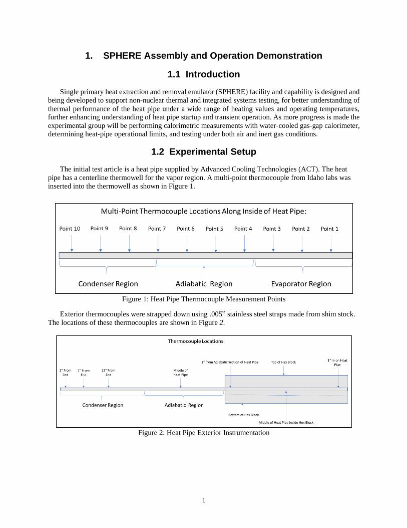
The initial test article is a heat pipe supplied by Advanced Cooling Technologies (ACT). The heat
pipe has a centerline thermowell for the vapor region. A multi-point thermocouple from Idaho labs was
inserted into the thermowell as shown in Figure 1.
Figure 1: Heat Pipe Thermocouple Measurement Points
Exterior thermocouples were strapped down using .005” stainless steel straps made from shim stock.
The locations of these thermocouples are shown in Figure 2.
Figure 2: Heat Pipe Exterior Instrumentation
2
Heater power control is achieved using Watlow Din-A-Mite silicon-controlled-rectifier (SCR)-based
power controllers, based on a 4–20 mA control signal provided from the National Instruments SCXI data-
acquisition system, which is interfaced to a LabVIEW virtual instrument for data acquisition and instrument
control. Pressure inside the heat pipes will be sub-atmospheric even at the highest operating temperature,
so any failure of the heat pipe would not involve a pressurized release of material. Power to each heater is
monitored continuously using precision power meters designed for measurement of SCR-controlled loads.
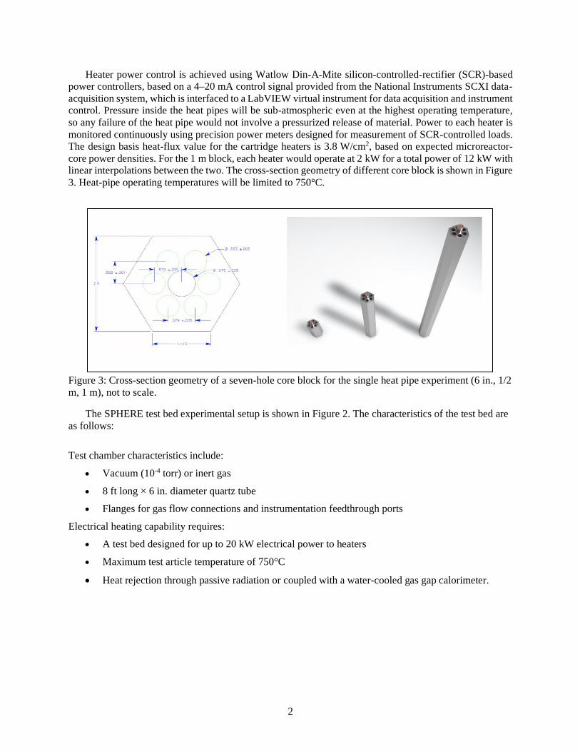
The design basis heat-flux value for the cartridge heaters is 3.8 W/cm2, based on expected microreactor-
core power densities. For the 1 m block, each heater would operate at 2 kW for a total power of 12 kW with
linear interpolations between the two. The cross-section geometry of different core block is shown in Figure
3. Heat-pipe operating temperatures will be limited to 750°C.
Figure 3: Cross-section geometry of a seven-hole core block for the single heat pipe experiment (6 in., 1/2
m, 1 m), not to scale.
The SPHERE test bed experimental setup is shown in Figure 2. The characteristics of the test bed are
as follows:
Test chamber characteristics include:
• Vacuum (10-4 torr) or inert gas
• 8 ft long × 6 in. diameter quartz tube
• Flanges for gas flow connections and instrumentation feedthrough ports
Electrical heating capability requires:
• A test bed designed for up to 20 kW electrical power to heaters
• Maximum test article temperature of 750°C
• Heat rejection through passive radiation or coupled with a water-cooled gas gap calorimeter.

3
Figure 4: SPHERE test bed and seven-hole test article.
The objectives and procedure are outlined for the shakedown test in Table 1.
Table 1: SPHERE Test Plan for Shakedown Testing
1.3 Experimental Test Results
A preliminary evaluation of heater vacuum performance without exterior insulation was performed.
Short distance heat pipe operation was observed as a secondary part of this heater testing. This is shown by
the bare hex-block being heated under direct observation. The heat pipe and the heaters were both inserted
in the block with centering wires and coated with boron nitride. The boron nitride provides a stable high
temperature interface between with the hex-block and the heaters and heat pipe. Post examination of the
hex-block showed some oxidation, but oxidation color did not correlate with normal open-air color of steel
at the heat treatment temperature.The visible spectrum thermal radiation can be seen in Figure 5. After

4
performing this heater test, the system was then insulated in preparation for testing the heat pipe
performance.
Figure 5: Optical image of heater test and initial short-heat pipe operation
The full shakedown testing used vacuum conditions as well as a 1-inch zirconia wool blanket (Zircar
refractory insulation) for the hex-block and a zirconia wool sock (1/8”) over adiabatic length of the heat
pipe. The results of the preliminary testing are shown in Figure 6. The data from this shakedown test follows
very closely with the manufacturer validation and characterization testing (Figure 7). The INL heat pipe
shows overall stronger thermal coupling in the condenser section. This is consistent with ACT having
blanketing on the condenser section, while the INL test left the condenser section bare.
Figure 6: Data from INL testing of ACT heat pipe
5
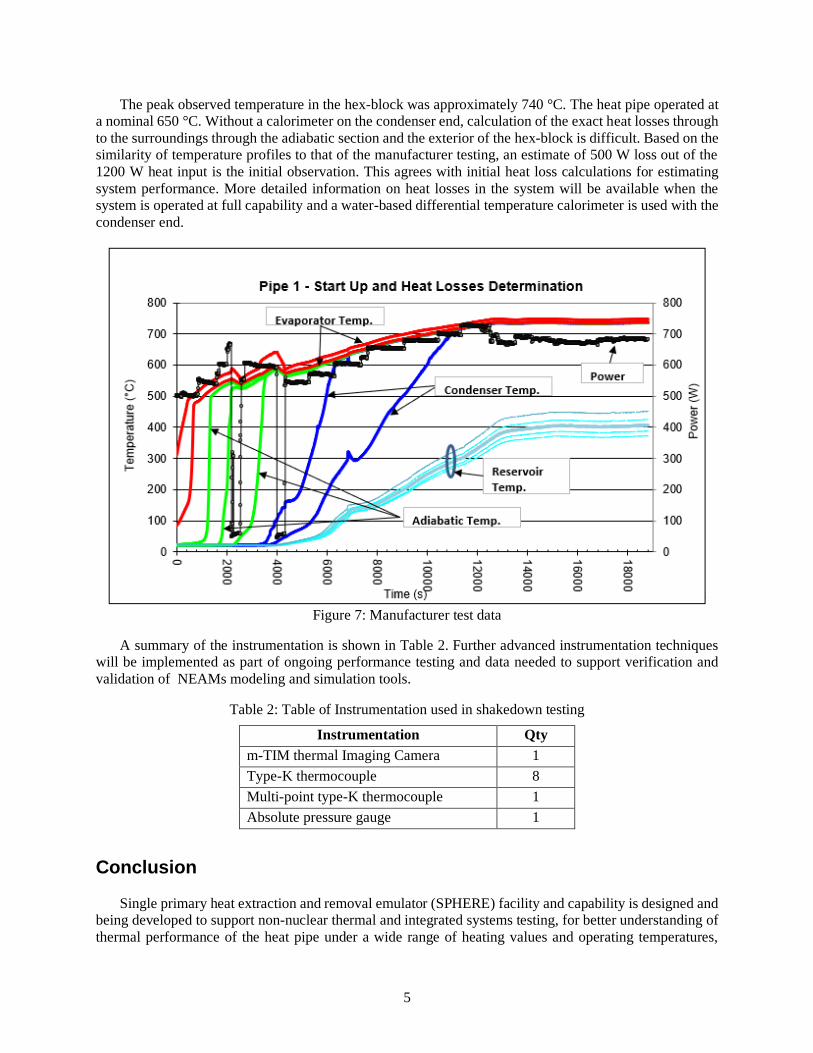
The peak observed temperature in the hex-block was approximately 740 °C. The heat pipe operated at
a nominal 650 °C. Without a calorimeter on the condenser end, calculation of the exact heat losses through
to the surroundings through the adiabatic section and the exterior of the hex-block is difficult. Based on the
similarity of temperature profiles to that of the manufacturer testing, an estimate of 500 W loss out of the
1200 W heat input is the initial observation. This agrees with initial heat loss calculations for estimating
system performance. More detailed information on heat losses in the system will be available when the
system is operated at full capability and a water-based differential temperature calorimeter is used with the
condenser end.
Figure 7: Manufacturer test data
A summary of the instrumentation is shown in Table 2. Further advanced instrumentation techniques
will be implemented as part of ongoing performance testing and data needed to support verification and
validation of NEAMs modeling and simulation tools.
Table 2: Table of Instrumentation used in shakedown testing
Instrumentation Qty
m-TIM thermal Imaging Camera 1
Type-K thermocouple 8
Multi-point type-K thermocouple 1
Absolute pressure gauge 1
Conclusion
Single primary heat extraction and removal emulator (SPHERE) facility and capability is designed and
being developed to support non-nuclear thermal and integrated systems testing, for better understanding of
thermal performance of the heat pipe under a wide range of heating values and operating temperatures,

6
further enhancing understanding of heat pipe startup and transient operation. The initial testing consisted
of vacuum operation of a sodium heat pipe. The temperature was measured at 10 evenly spaced points along
the heat pipe. Additional exterior thermocouple measurements were also taken on the exterior of the heat
pipe to confirm the similarity of thermowell temperatures to exterior heat pipe temperature measurements.
The initial test were successfully completed and results measured at INL are consistent with the data from
the manufacturer. In future, the experimental group will be performing calorimetric measurements with
water-cooled gas-gap calorimeter, determining heat-pipe operational limits, and testing under both air and
inert gas conditions.