sph 618 optical and laser physics university of nairobi, …mitr.p.lodz.pl/raman/lecture4-sph...
TRANSCRIPT

SPH 618Optical and Laser Physics
University of Nairobi, KenyaLecture 4
Non-linear effects
Prof. Dr Halina AbramczykMax Born Institute for Nonlinear Optics and Ultrashort Laser
Pulses, Berlin, Germany,Technical University of Lodz, Lodz, Poland
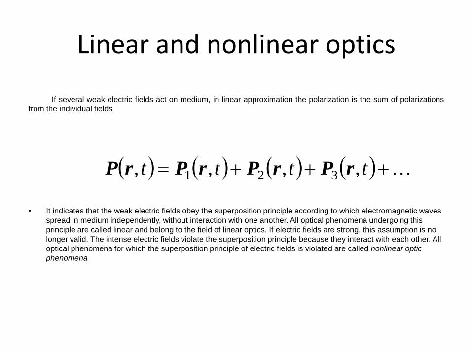
Linear and nonlinear optics
If several weak electric fields act on medium, in linear approximation the polarization is the sum of polarizations
from the individual fields
• It indicates that the weak electric fields obey the superposition principle according to which electromagnetic waves
spread in medium independently, without interaction with one another. All optical phenomena undergoing this
principle are called linear and belong to the field of linear optics. If electric fields are strong, this assumption is no
longer valid. The intense electric fields violate the superposition principle because they interact with each other. All
optical phenomena for which the superposition principle of electric fields is violated are called nonlinear optic
phenomena
tttt ,,,, 321 rPrPrPrP
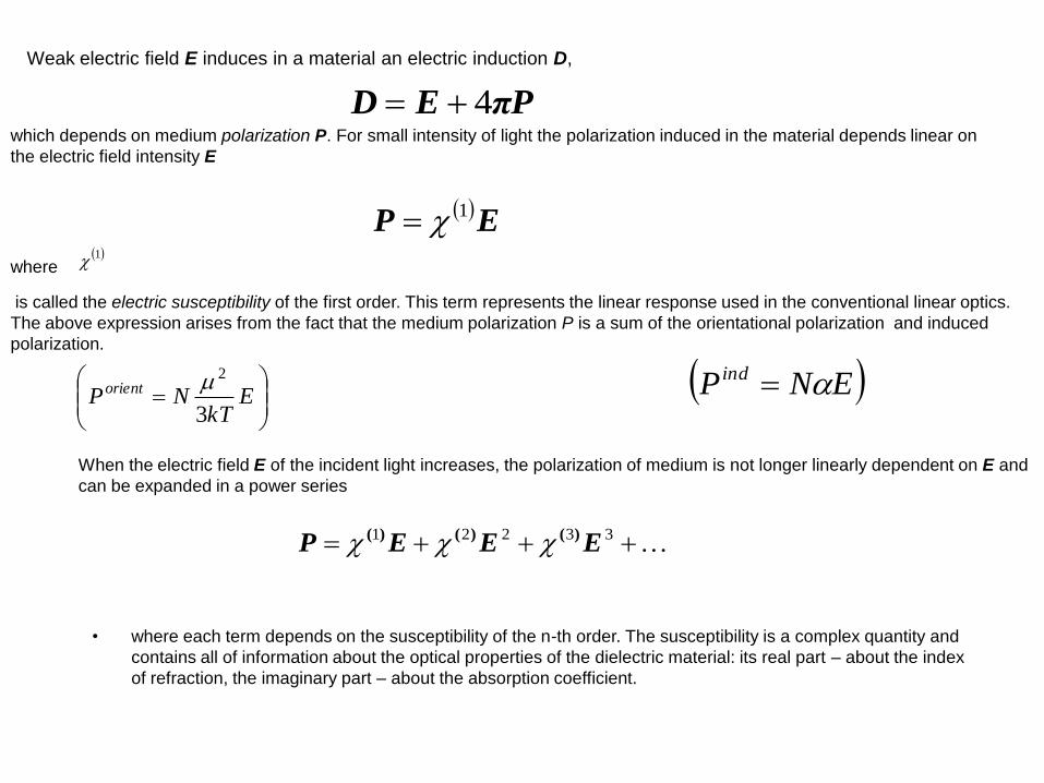
Weak electric field E induces in a material an electric induction D,
PπED 4which depends on medium polarization P. For small intensity of light the polarization induced in the material depends linear on
the electric field intensity E
EP 1
where 1
is called the electric susceptibility of the first order. This term represents the linear response used in the conventional linear optics.
The above expression arises from the fact that the medium polarization P is a sum of the orientational polarization and induced
polarization.
E
kTNPorient
3
2 ENP ind
When the electric field E of the incident light increases, the polarization of medium is not longer linearly dependent on E and
can be expanded in a power series
• where each term depends on the susceptibility of the n-th order. The susceptibility is a complex quantity and
contains all of information about the optical properties of the dielectric material: its real part – about the index
of refraction, the imaginary part – about the absorption coefficient.
33221 EEEP )()()(
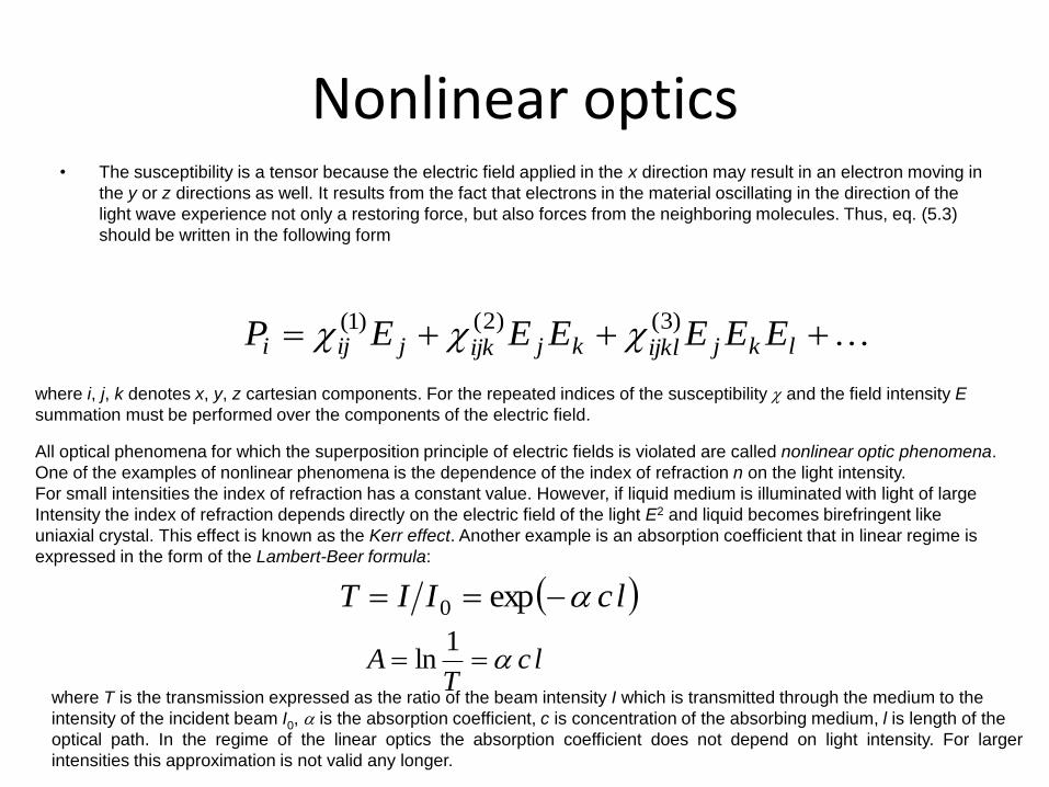
Nonlinear optics• The susceptibility is a tensor because the electric field applied in the x direction may result in an electron moving in
the y or z directions as well. It results from the fact that electrons in the material oscillating in the direction of the
light wave experience not only a restoring force, but also forces from the neighboring molecules. Thus, eq. (5.3)
should be written in the following form
lkjijklkjijkjiji EEEEEEP)3()2()1(
where i, j, k denotes x, y, z cartesian components. For the repeated indices of the susceptibility and the field intensity E
summation must be performed over the components of the electric field.
All optical phenomena for which the superposition principle of electric fields is violated are called nonlinear optic phenomena.
One of the examples of nonlinear phenomena is the dependence of the index of refraction n on the light intensity.
For small intensities the index of refraction has a constant value. However, if liquid medium is illuminated with light of large
Intensity the index of refraction depends directly on the electric field of the light E2 and liquid becomes birefringent like
uniaxial crystal. This effect is known as the Kerr effect. Another example is an absorption coefficient that in linear regime is
expressed in the form of the Lambert-Beer formula:
lcIIT exp0
lcT
A 1
ln
where T is the transmission expressed as the ratio of the beam intensity I which is transmitted through the medium to the
intensity of the incident beam I0, is the absorption coefficient, c is concentration of the absorbing medium, l is length of the
optical path. In the regime of the linear optics the absorption coefficient does not depend on light intensity. For larger
intensities this approximation is not valid any longer.
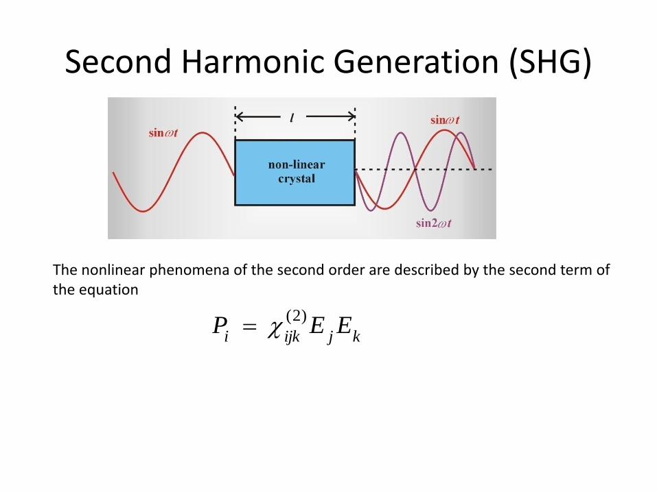
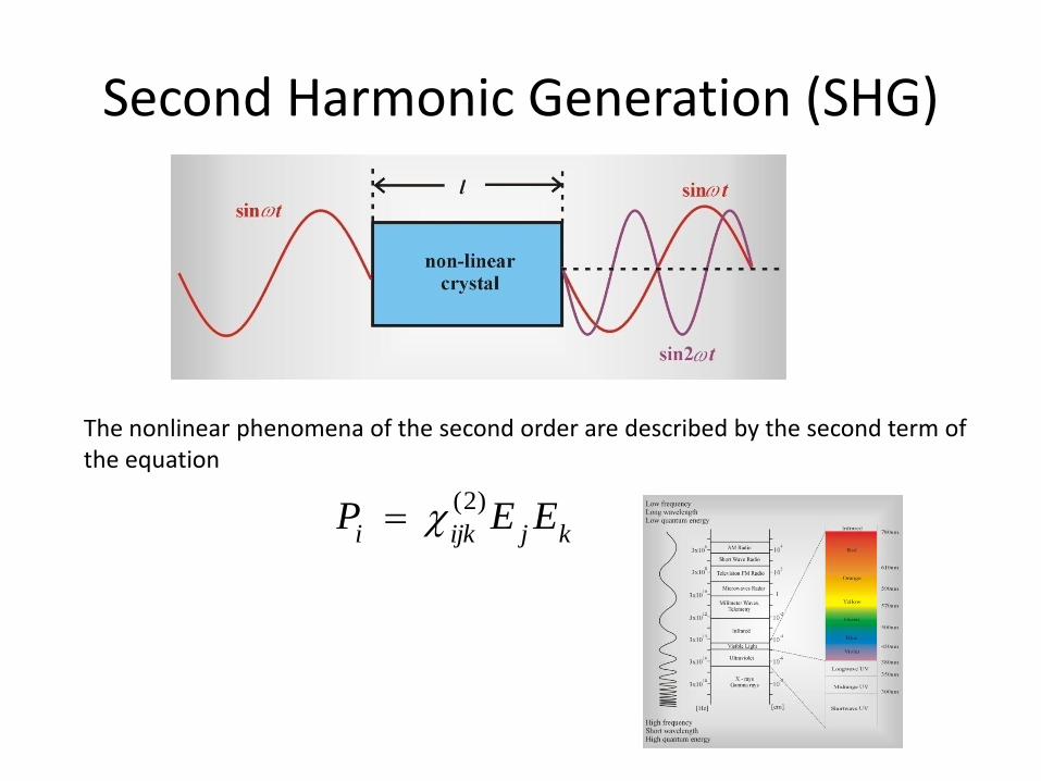
Second Harmonic Generation (SHG)
The nonlinear phenomena of the second order are described by the second term of the equation
kjijkiEEP
)2(

The second harmonic generation was demonstrated for the first time in 1961 when the light from the ruby laser illuminating quartz produced coherent ultraviolet light. The light of the ruby laser at wavelength of 694.3 nm was directed onto a nonlinear crystal. By changing the angle between the direction of the laser beam and the direction of the crystal optic axis, it was noticed
that at certain angles the output beam from the crystal has two components: 694.3 nm and 694.3 nm / 2 = 347.15 nm. Therefore,besides the fundamental component 694.3 nm, which does not change its frequency after passage through the crystal, an
additional component appears with the frequency twice the fundamental frequency) called the second harmonic.
tEtEtEtP ijkkjijki 1122
0)2()2()2( cos,,, rkrrr
coscos2 1 2
2x
x
tEE
tP ijkijki 112011
)2(20)2()2( 2cos2,2
2
1
2)0(, rkkr
using
Thus, the polarization induced by interaction of two waves of frequency w1 each consists of two terms: a constant
time independent polarization 20
)2(
21 )0( Eijk and the polarization modulated at the frequency 21.
Second Harmonic Generation (SHG)
The nonlinear phenomena of the second order are described by the second term of the equation
kjijkiEEP
)2(

The phase matching condition
• The phase matching condition is fulfilled only when• .• The phase matching condition can be written more generally as• (5.14)• or• . (5.15)• Since the wave vector k is related to the photon momentum p ( ), this condition simply
indicates that the energy exchange between the waves is possible only when the momentum conservation law for three photons participating in the process of frequency mixing is not violated. When all the beams are collinear, the condition (5.14) may be replaced by
• , (5.16)• where we employed the relation For the second harmonic with 1 = 2 and , eq.
(5.16) takes the form• . (5.17)• This indicates that the second harmonic may be generated efficiently only when the index of
refraction at 21 is equal to the index of refraction at 1. In most cases it is impossible due to dispersion of the material, which simply means that two waves differing in the wavelength, have different indices of refraction as well. However, we can use some tricks related to the properties of birefringent crystals.
•
111112 2 kkk
221133 kkk
0221133 kkkk
221133 nnn
112 nn
kp
0k
)(
n
c
kph
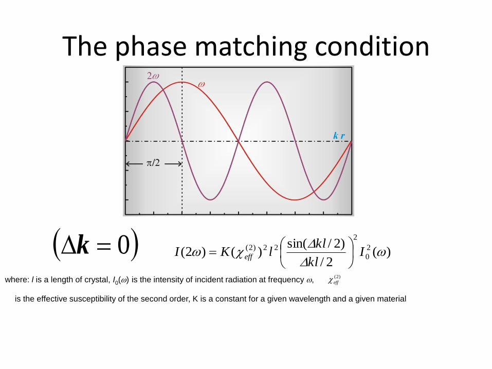
The phase matching condition
0k )(2/
)2/sin()()2( 2
0
2
22)2(
I
kl
kllKI eff
where: l is a length of crystal, I0() is the intensity of incident radiation at frequency , )2(
eff
is the effective susceptibility of the second order, K is a constant for a given wavelength and a given material

How to achieve the high SHG efficiency?
This can be achieved by employing:
• laser pulses of high incident intensity I0; the magnitude of I0 are limited by a crystal damage threshold,
• nonlinear materials of high (2) susceptibility,
• phase matching condition k = 0,
• long optical path l.
However, material thickness l is limited by a certain critical value lcoh, called the coherence length.
One can see from fig. 5.3 that the fundamental wave at frequency and the SHG wave traveling along the
crystal are more and more out of phase leading to destructive interference and reducing the second harmonic intensity.
The distance from the entrance surface of the crystal to the point where the second harmonic intensity has its first maximum
has been termed the coherence length lcoh. If the crystal length happens to be an odd multiple of the coherence length,
no second-harmonic light will be emitted.
)(2/
)2/sin()()2( 2
0
2
22)2(
I
kl
kllKI eff
The coherence length can be roughly estimated from its definition
2
cohlk
nnklcoh
242
π
Scheme illustrating the crystal coherence length

How to achieve the condition of phase matching for SHG in dispersive media?
112 nn
birefringence

birefringent crystals
The birefringence can be observed when light passes through many crystals, including calcite, ice, quartz, mica, sugar,
that are anisotropic and have the optic axes. In such crystals the light beam undergoing refraction divides into two rays
in contrast to the isotropic media (liquids, gases, glasses) that show only one ray. The two rays are called the ordinary (o)
and extraordinary (e) rays and have the different phase velocities and the different indices of refraction.
This phenomenon is called double refraction or birefringence and was discovered by Bartholinus and Huygens.
They found that both rays are polarized linearly in planes perpendicular to each other.
2
1
n
n
s
in
sin
the ordinary and extraordinary
beams do not propagate along the
same line, the beam is divided onto two orthogonally polarized beams separated by called the walk-off distance

birefringent crystals
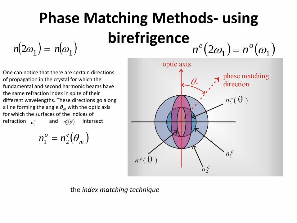
Phase Matching Methods- using birefrigence
112 nn 112 oe nn
One can notice that there are certain directions of propagation in the crystal for which the fundamental and second harmonic beams have the same refraction index in spite of their different wavelengths. These directions go along a line forming the angle θm with the optic axis for which the surfaces of the indices of refraction and intersecton1
en2
m
eo nn 21
the index matching technique
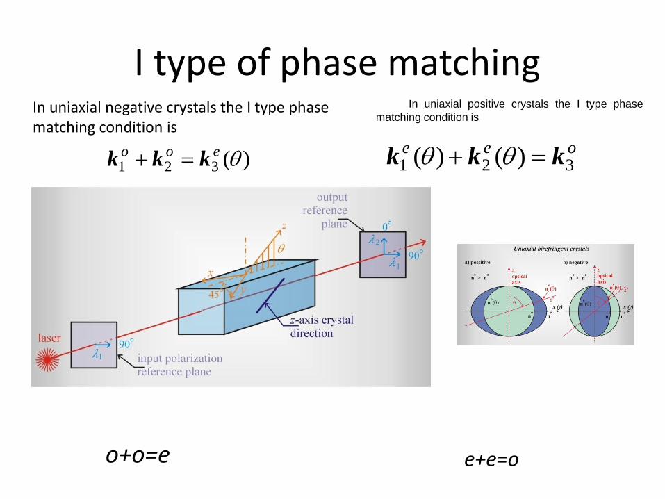
I type of phase matching
o+o=e
In uniaxial negative crystals the I type phase matching condition is
)(321 eookkk
In uniaxial positive crystals the I type phase
matching condition is
oee321 )()( kkk
e+e=o

I type of phase matching
• If the mixing waves at frequencies 1 and 2
have the same polarization and the sum frequency wave 3 = 1+2 (SFG) is polarized perpendicularly to their incident polarization, I type of phase matching takes place.

II type of phase matching In uniaxial negative crystals the II type phase
matching condition occurs when
)()( 321 eeokkk
e+o=e
In uniaxial positive crystals the II type phase matching occurs when
oeo321 )( kkk
o+e=o
If the mixing waves at frequencies 1 and 2 are of orthogonal polarization, the II type phase matching occurs

However, an additional difficulty with SHG process is that the energy of the two beams, the fundamental and the second harmonic that are orthogonally polarized will propagate in different directions, characterized by the walk-off
distance . This comes from the fact that in a birefringent crystal the direction of propagation of the wave phase (wave vector k) generally does not coincide with that of the wave energy (Poynting vector s). The direction of Poynting vector s is defined as the normal to the tangent drawn at the point of intersection of wave vector k with n() cross section .
One can see that for the ordinary beam both vectors coincide in contrast to the extraordinary beam.
Directions of the wave vector k and the energy wave (Poynting vector) s for (a) ordinary beam; extraordinary beam in
negative (b) and positive (c) uniaxial crystal

This disadvantage of the angle-tuned phase matching technique can be eliminated by employing crystals with the phase matching angle m = 90○. In this case the direction of propagation and the optic axis is set to 90○ and
the angle between the Poynting vectors for the two beams is zero.

In systems having the macroscopic center of inversion (liquids, gases, crystals of some classes) it is impossible to generate the second harmonic. Indeed, if the system has the center of inversion, the polarization P = f(E) is an odd function of the electric field This indicates that the second term in equation
has to vanish during one period of the electric field oscillation. The medium can produce the second harmonic only when P = f(E) dependence looks like that in figure on right that takes place only when there is no macroscopic center of inversion.Therefore, the second harmonic generation is limited to:some classes of crystals (without the macroscopic inversion symmetry),surfaces of a medium, gas or liquid systems in which the isotropy has been broken by an electric field or or a density gradient.
33221 EEEP )()()(

Material
Phase-
matching
type
Effective
nonlinear
coefficient*
[10-12 m/V]
index of
refraction
n0()
Damage
threshold
[GW/cm2]
Absorption
[cm-1]
Phase
matching
angle
Walk-off
angle
KD*P II 0.37 1.49 0.5 0.005 53.7 1.45
KTP II 3.18 1.74 0.5 0.010 24.3 0.26
LBO I 1.16 1.56 2.5 0.005 - -
BBO I 1.94 1.62 1.5 0.005 22.8 3.19
LiNbO3
(5%MgO)I 4.7 2.23 0.10 0.002 90 (1) 0
Properties of important nonlinear materials and phase matching parameters 5.1
* For 1064 nm to 532 nm second-harmonic generation, (1) at T = 107C
SHG for Pico- and FemtosecondPulses
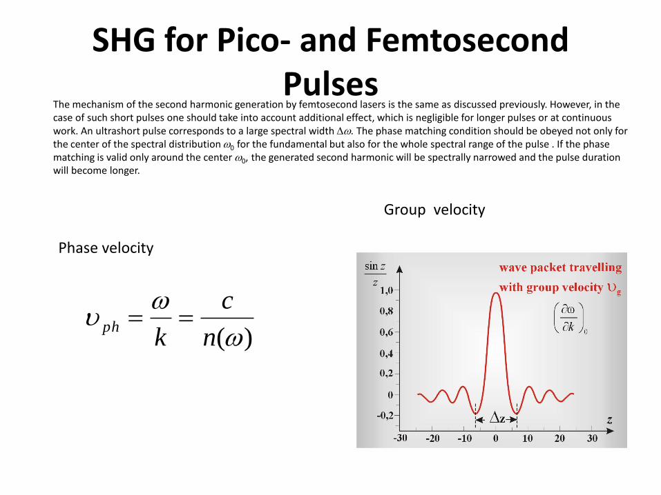
The mechanism of the second harmonic generation by femtosecond lasers is the same as discussed previously. However, in thecase of such short pulses one should take into account additional effect, which is negligible for longer pulses or at continuouswork. An ultrashort pulse corresponds to a large spectral width . The phase matching condition should be obeyed not only for the center of the spectral distribution0 for the fundamental but also for the whole spectral range of the pulse . If the phasematching is valid only around the center 0, the generated second harmonic will be spectrally narrowed and the pulse durationwill become longer.
)(
n
c
kph
Phase velocity
Group velocity

Assume the second harmonic is generated under the phase matching condition in a crystal of length l by pulses of duration tp. It indicates that the phase velocities of the fundamental beam and the second harmonic are equal for a given component
It does not mean, however, that the group velocities are also equal. The group velocities of the fundamental beam and the second harmonic are usually different due to the dispersion properties of the crystal.
The consequence of the different group velocities is the different time tg of a passage through a crystal of length l for the fundamental beam and the second harmonic.
Another parameter important for ultrashort pulses related to dispersion properties is the group delay.
2phph )(
n
c
kph
This indicates that the second harmonic wave packet is delayed with respect to the fundamental wave packet by t

SHG for Pico- and FemtosecondPulses
• The greater the group delay time, , the shorter the length of interaction between the fundamental and the second harmonic beams.
1g
2g ttt
The interaction length is limited by the condition
ptt
This condition defines the effective crystal length l. If the crystal is longer than l leading to the violation of the condition
(5.41), the rest of the crystal is ineffective because the beams do not overlap any longer and the SHG process does not occur.
Forpg tt the second harmonic intensity does not increase with crystal length but a temporal
pulse stretching occurs.

Optical Parametric Oscillator (OPO)
The parametric conversion can be described as inelastic scattering of a pumping photon p on a crystal lattice. As a result of interaction,
two photons: s and i are generated. The component with the frequency i is called the idler component,
and the component s – the signal component. The energy conservation law requires
sip
sip kkk 0 sipk kkk
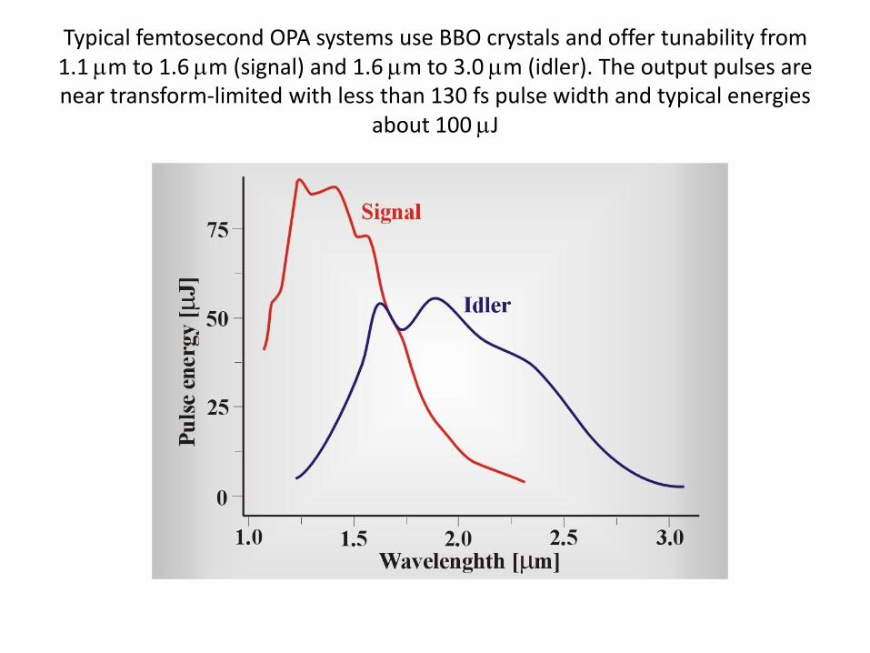
Typical femtosecond OPA systems use BBO crystals and offer tunability from 1.1 m to 1.6 m (signal) and 1.6 m to 3.0 m (idler). The output pulses are near transform-limited with less than 130 fs pulse width and typical energies
about 100 J
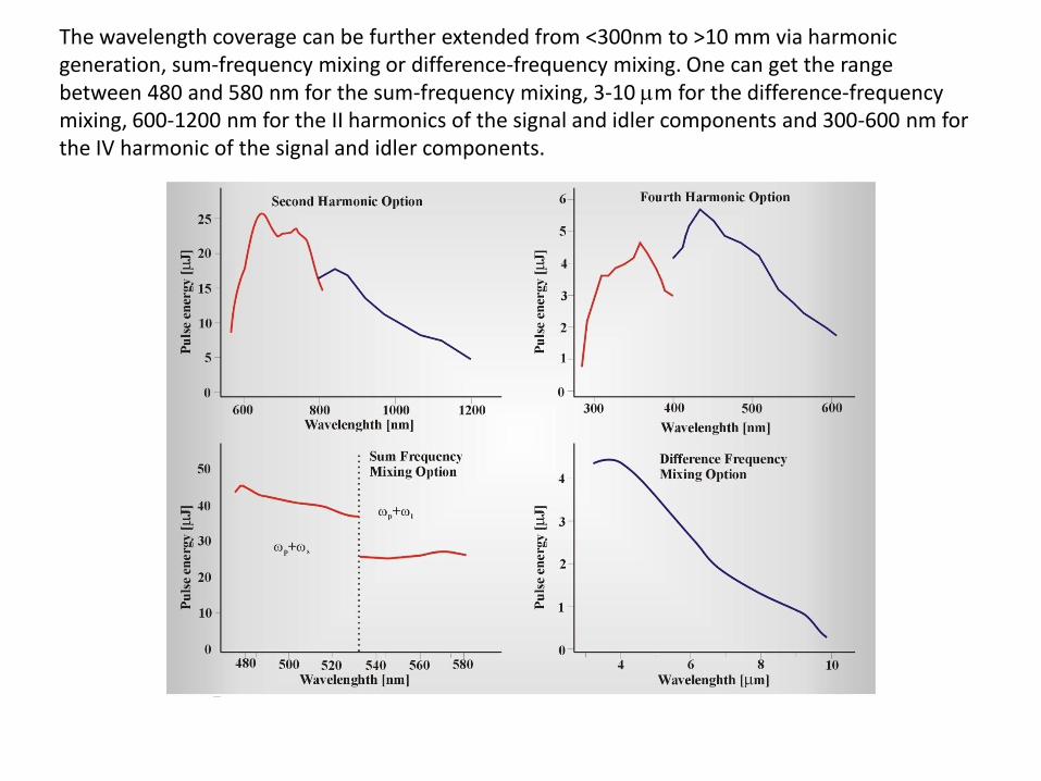
The wavelength coverage can be further extended from <300nm to >10 mm via harmonic generation, sum-frequency mixing or difference-frequency mixing. One can get the range between 480 and 580 nm for the sum-frequency mixing, 3-10 m for the difference-frequency mixing, 600-1200 nm for the II harmonics of the signal and idler components and 300-600 nm for the IV harmonic of the signal and idler components.

optical parametric amplifier (OPA)

OPO, OPA, OPG
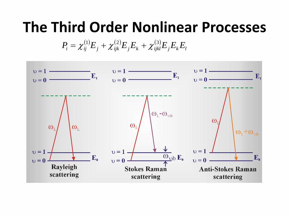
The Third Order Nonlinear Processes
lkjijklkjijkjiji EEEEEEP 321

Spontaneous Raman scattering
• The levels denoted as E0 and E1 represent electronic energy levels while the levels numbered with a quantum number represent the vibrational levels. If the sample is illuminated with photons of energy , smaller than the resonance energy , all of the photons that interact with the sample are not absorbed, but cause the potential energy of the interacting molecules to be raised to virtual state, above the ground state. Almost immediately most molecules return to the ground state through the emission of photons of the same energy as the incident photons. This elastic scattering is called the Rayleigh scattering. A small fraction of the molecules drops back to the first excited vibrational state ( = 1) instead to the ground state. Since the energy of the incident and the scattered photons are different, the scattering is inelastic and the process is known as Stokes Raman scattering with the scattered radiation observed at lower energy . Molecules that are already in the excited vibrational state ( = 1) will undergo analogous effect when illuminated with a laser light. When the excited molecules drops back to the ground vibrational state ( = 0), the scattered radiation will be observed at higher energy . This scattering is known as anti-Stokes Raman scattering, The frequency vib denotes the frequency of a given vibrational mode of the molecule.
EP 1

Spontaneous Raman scattering
• To describe Raman scattering a fully quantum-mechanical theory is required but some intuitive description can be also obtained from a classical picture. The electric field drives the electron displacements that induce the polarization P in a medium modulated in time that in turn generates a wave at the same frequency L (Rayleigh scattering). When the dipole oscillations are modulated additionally by the molecule vibrations at frequency vib
the waves at ( ) (Stokes Raman scattering) or ( ) (anti-Stokes Raman scattering) are generated.
tE L rkcos0
vibL vibL
EP 1

• When more intense light is employed nonlinear Raman processes occur in the material
• hyper Raman or
• stimulated Raman scattering
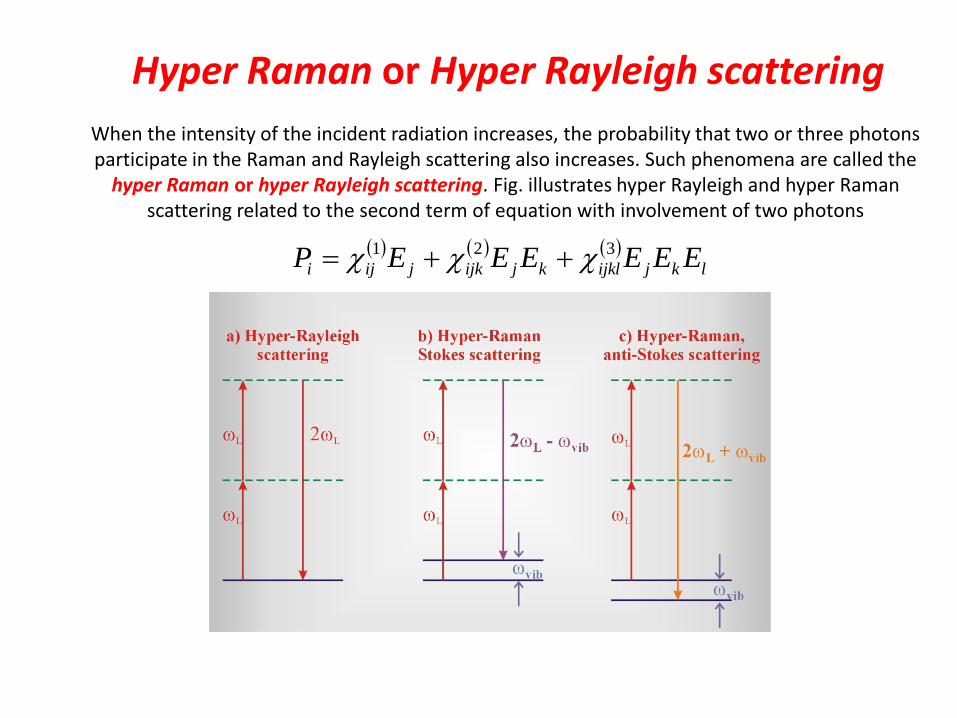
Hyper Raman or Hyper Rayleigh scattering
When the intensity of the incident radiation increases, the probability that two or three photons participate in the Raman and Rayleigh scattering also increases. Such phenomena are called the
hyper Raman or hyper Rayleigh scattering. Fig. illustrates hyper Rayleigh and hyper Raman scattering related to the second term of equation with involvement of two photons
lkjijklkjijkjiji EEEEEEP 321
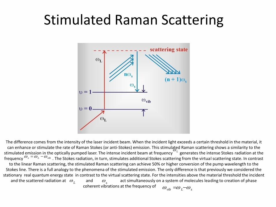
Stimulated Raman Scattering
The difference comes from the intensity of the laser incident beam. When the incident light exceeds a certain threshold in the material, it can enhance or stimulate the rate of Raman Stokes (or anti-Stokes) emission. This stimulated Raman scattering shows a similarity to the
stimulated emission in the optically pumped laser. The intense incident beam at frequency generates the intense Stokes radiation at the frequency . The Stokes radiation, in turn, stimulates additional Stokes scattering from the virtual scattering state. In contrast
to the linear Raman scattering, the stimulated Raman scattering can achieve 50% or higher conversion of the pump wavelength to the Stokes line. There is a full analogy to the phenomena of the stimulated emission. The only difference is that previously we considered the
stationary real quantum energy state in contrast to the virtual scattering state. For the intensities above the material threshold the incident and the scattered radiation at and act simultaneously on a system of molecules leading to creation of phase
coherent vibrations at the frequency of .
L
vibLs
L
s
sLvib

Stimulated Raman Scattering
The stimulated Raman scattering is a special case of four-wave interaction
3214 04321 kkkkk
2
2223
2/
2/)(
kl
klsinlIIconstI SL
SRS
S
For the stimulated Stokes scattering the phase matching condition is given by
04321 kkkkk
is established automatically

Direction of stimulated anti-Stokes scattering
The stimulated anti-Stokes scattering in turn, can be described as fully non-degenerated four-wave interaction
s LLvibLAS
ASSLASSLL kkkkkkkk 2
This indicates that the phase matching condition is achieved only for certain directions for which the relation occurs
SAS kkk L2
the direction of wave propagation of the stimulated anti-Stokes scattering is limited to the cone surface with the axis parallel to the direction of the incident laser beam
SAS kkk L2
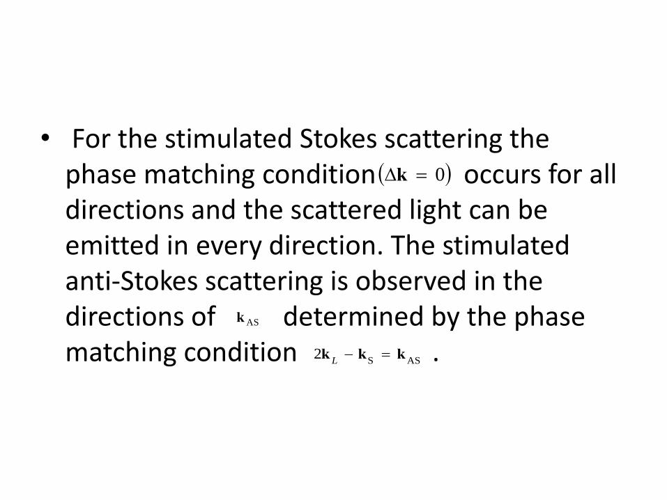
• For the stimulated Stokes scattering the phase matching condition occurs for all directions and the scattered light can be emitted in every direction. The stimulated anti-Stokes scattering is observed in the directions of determined by the phase matching condition .
0k
ASk
ASS2 kkk
L

CARS- Coherent anti-Stokes Raman scattering
CARS (and CSRS) are techniques based on SRS (stimulated Raman Scattering) that use two laser beams to excite a sample: at the frequency and (instead of one at the frequency in SRS). The phenomena are similar to those described in the
previous section, but the CARS (and CSRS) signals are much stronger. Moreover, by tuning the frequency (or ) to the resonance with a molecular vibration it is possible to excite most of the vibrations in contrast to SRS for which
only the strongest vibrational lines could be observed.
L S L
S L
vibSL
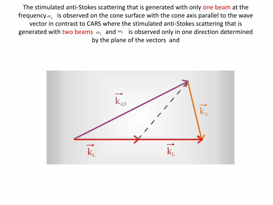
The stimulated anti-Stokes scattering that is generated with only one beam at the frequency is observed on the cone surface with the cone axis parallel to the wave
vector in contrast to CARS where the stimulated anti-Stokes scattering that is generated with two beams and is observed only in one direction determined
by the plane of the vectors and
L
SL

Besides the coherent stimulated anti-Stokes (CARS) and Stokes (CSRS) Raman scattering there are many other techniques of the coherent stimulated Raman effect, such as SRGS (Stimulated Raman Gain Spectroscopy) and IRS (Inverse Raman Scattering). The
nonlinear four-wave interaction of the incident beams at frequencies or with the electric field originating from the coherent vibrations of molecules at the frequency vib can cause the gain not only at the frequency (CSRS) and
(CARS) but also the Stokes gain or the intensity loss of the incident beam . The former method related to the Stokes gain is known as SRGS (Stimulated Raman Gain Stokes) method and the latter is known as IRS (Inverse Raman Scattering). The schematic
diagram of the most commonly used Raman techniques is presented in fig.
L S
LS 2 SL 2
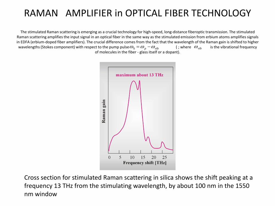
RAMAN AMPLIFIER in OPTICAL FIBER TECHNOLOGY
The stimulated Raman scattering is emerging as a crucial technology for high-speed, long-distance fiberoptic transmission. The stimulated Raman scattering amplifies the input signal in an optical fiber in the same way as the stimulated emission from erbium atoms amplifies signals in EDFA (erbium-doped fiber amplifiers). The crucial difference comes from the fact that the wavelength of the Raman gain is shifted to higher wavelengths (Stokes component) with respect to the pump pulse ( ; where is the vibrational frequency
of molecules in the fiber - glass itself or a dopant).
Cross section for stimulated Raman scattering in silica shows the shift peaking at a frequency 13 THz from the stimulating wavelength, by about 100 nm in the 1550 nm window
vibp S vib

RAMAN AMPLIFIER in OPTICAL FIBER TECHNOLOGY
In the usual configuration the Raman amplification occurs in the final length of fiber before the receiver or EDFA The signal and pump beams travel in the opposite directions, with the pump coupled into the fiber at the receiver end. A coupler directs the
pump light into the transmitting fiber, while diverting signals arriving through the fiber to the receiver or EDFA.
Distributed Raman amplification amplifies signals passing through fiber in the transmission cable by transferring energy from a strong pump beam to the less powerful signal wavelengths
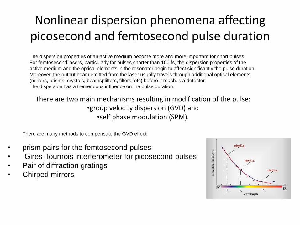
Nonlinear dispersion phenomena affecting picosecond and femtosecond pulse duration
The dispersion properties of an active medium become more and more important for short pulses.
For femtosecond lasers, particularly for pulses shorter than 100 fs, the dispersion properties of the
active medium and the optical elements in the resonator begin to affect significantly the pulse duration.
Moreover, the output beam emitted from the laser usually travels through additional optical elements
(mirrors, prisms, crystals, beamsplitters, filters, etc) before it reaches a detector.
The dispersion has a tremendous influence on the pulse duration.
There are two main mechanisms resulting in modification of the pulse:•group velocity dispersion (GVD) and
•self phase modulation (SPM).
There are many methods to compensate the GVD effect
• prism pairs for the femtosecond pulses
• Gires-Tournois interferometer for picosecond pulses
• Pair of diffraction gratings
• Chirped mirrors

Perfect modelocking
The magnitude of the product Et
depends on a temporary pulse shape.
Assume that the temporary pulse shape
is described by a Gaussian function
2
20
2exp)(
tEtE
The frequency spectrum )(E
can be obtained from the Fourier transform
20
20
2exp
2)(
2
1)(
E
dtetEE ti
Thus, for the Gaussian profile the product Et is equal to 4410.t FWHHFWHH
FWHHt
FWHH
The relation derived in eq. corresponds to an ideal situation of a perfectly modelocked laser with a pulse called the Fourier-transform limited pulse.
Such a pulse is the shortest pulse
that can be generated for a given gain spectrum
In practice such pulses are seldom produced.

Real world (dispersion)
To produce pulses as short as possible, dispersion in the cavity must be compensated for by adding optical elements – typically pairs of prisms or gratings, specially coated mirrors or a length of optical fiber
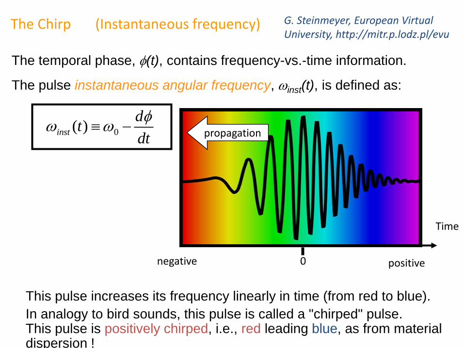
The temporal phase, (t), contains frequency-vs.-time information.
The pulse instantaneous angular frequency, inst(t), is defined as:
The Chirp (Instantaneous frequency)
0( )inst
dt
dt
This pulse increases its frequency linearly in time (from red to blue).
In analogy to bird sounds, this pulse is called a "chirped" pulse.This pulse is positively chirped, i.e., red leading blue, as from materialdispersion !
Time
positivenegative
propagation
0
G. Steinmeyer, European Virtual University, http://mitr.p.lodz.pl/evu
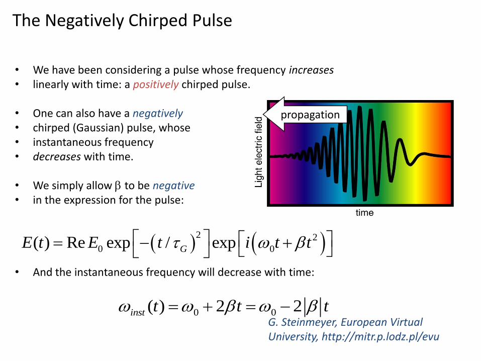
The Negatively Chirped Pulse
• We have been considering a pulse whose frequency increases• linearly with time: a positively chirped pulse.
• One can also have a negatively • chirped (Gaussian) pulse, whose • instantaneous frequency • decreases with time.
• We simply allow to be negative• in the expression for the pulse:
• And the instantaneous frequency will decrease with time:
2 2
0 0( ) Re exp / expGE t E t i t t
0 0( ) 2 2inst t t t
propagation
G. Steinmeyer, European Virtual University, http://mitr.p.lodz.pl/evu

Prism pairs for the femtosecond
pulses
A positively chirped pulse from the cavity of the resonator travels to the prism P1, where the different spectral components of the pulse are separated. Then, the broadened pulse enters the prisms P2 and P3 at the Brewster angle (to minimize losses). Since the glass of the prisms exhibits a positive GVD, the red wavelengths exhibit larger group velocities than the blue wavelengths of the pulse. However, the red wavelengths travel a longer path length in the prisms P2 and P3 than the blue wavelengths. By translating prisms P2 and P3 perpendicularly to their bases, it is possible to select such a length of the optical path for which the group velocity dispersion will be compensated. As a consequence, all spectral components of the pulse reach the prism P4 at the same time, the pulse is free of chirping. As a consequence the output pulse is shorter than the input pulse and has an ideal shape, free of GVD effects. The prism
P4 liquidates the spatial distribution of the spectral components.

Gires-Tournois interferometer for picosecond pulses
In picosecond lasers GVD compensation is usually performed with a Gires-Tournoisinterferometer. The Gires-Tournois interferometer consists of a pair of parallel surfaces spaced by d. One surface is a partial reflector (reflectivity r <<100%), while the other one has 100% reflectivity. Typical spacing is on the order of a few dozen micrometers, and the reflectivity r is on the order of several percent
Group delay time tg as a function of wavelength for a Gires-Tournois interferometer

pair of diffraction gratings
During the propagation in the fiber the pulse is affected both by SPM and GVD. The resulting pulse has its spectral
width significantly increased with a significant positive chirp, which is almost linear. Then, the positively chirped pulse
passes through an external pair of gratings, which are designed to produce negative GVD. The negative GVD designed
pair of grating offset the positive chirp from the positive GVD and SPM by making the optical path length of the redder
components substantially greater than the path for the bluer components. Therefore, the trailing bluer edge of the pulse
catches up to the leading redder edge, and all components begin to travel at the same velocity. As a result, the output
pulse exhibits zero GVD, and is compressed to less than its initial value.

Bragg
R. Szipöcs et al., Opt. Lett. 19, 201 (1994)
Chirped mirrors
A chirped mirror is a dielectric mirror with chirped spaces—spaces of varying depth designed to reflect varying wavelengths of lights—between the dielectric layers (stack).Chirped mirrors are used in applications like lasers to reflect a wider range of light wavelengths than ordinary dielectric mirrors, or to compensate for the dispersion of wavelengths that can be created by some optical elements
G. Steinmeyer, European Virtual University, http://mitr.p.lodz.pl