spe/iadc 173103 wellbore tortuosity analysed by a novel
TRANSCRIPT

SPE/IADC 173103
Wellbore Tortuosity Analysed by a Novel Method
May Help to Improve Drilling, Completion, and
Production Operations
Jon Bang, Onyemelem Jegbefume, Adrián Ledroz, Gyrodata Inc.,
Jay Thompson, SandRidge Energy
Contents
• Background
• Description of analysis
• Examples of field results
• Conclusions
Slide 2
SPE/IADC 173103 • Wellbore tortuosity • Jon Bang
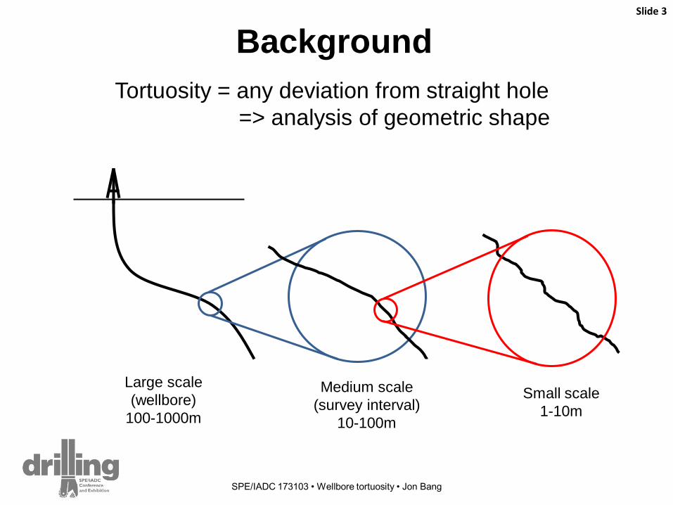
Background
Tortuosity = any deviation from straight hole
=> analysis of geometric shape
Slide 3
SPE/IADC 173103 • Wellbore tortuosity • Jon Bang
Large scale
(wellbore)
100-1000m
Medium scale
(survey interval)
10-100m
Small scale
1-10m

Medium and small scale tortuosity
cause problems
Slide 4
SPE/IADC 173103 • Wellbore tortuosity • Jon Bang
Drilling Completion Production
High friction, high torque and drag X
Stuck equipment Drill pipe, casing, liner, compl&prod equipment
X X
Reduced drilling length X
Excess bending, increased wear Casing, tubing, rods, rod guides
X X
Damage, premature failure of equipment Electrical submersible pumps (ESP)
X X
Consequences: - Increased energy consumption
- Equipment failure
- Increased work-over frequency
- Loss of production
- Increased costs, reduced profit
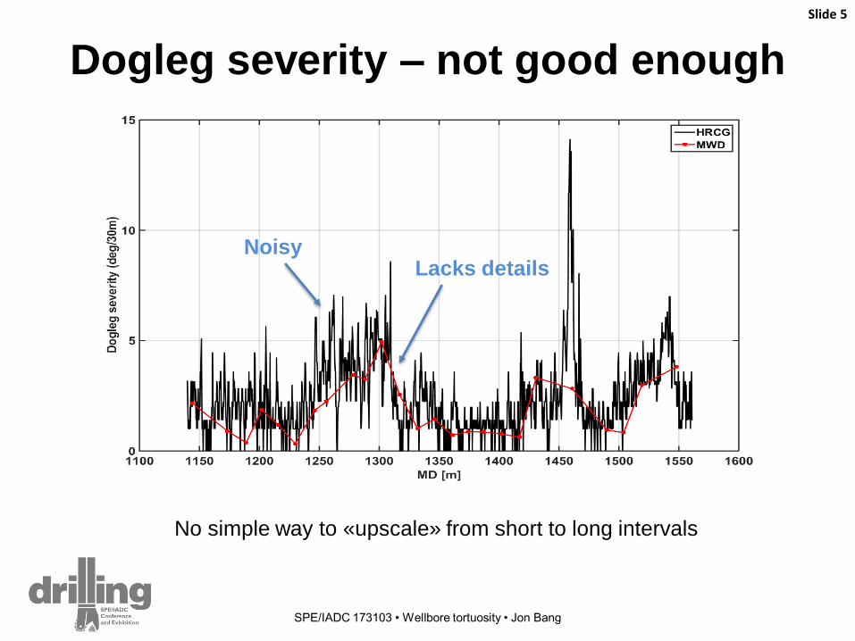
Dogleg severity – not good enough
Slide 5
SPE/IADC 173103 • Wellbore tortuosity • Jon Bang
Lacks details Noisy
No simple way to «upscale» from short to long intervals
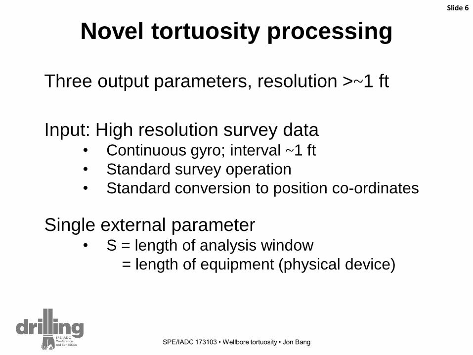
Novel tortuosity processing
Slide 6
SPE/IADC 173103 • Wellbore tortuosity • Jon Bang
Input: High resolution survey data • Continuous gyro; interval ~1 ft
• Standard survey operation
• Standard conversion to position co-ordinates
Three output parameters, resolution >~1 ft
Single external parameter • S = length of analysis window
= length of equipment (physical device)

S
1. Tortuosity parameter: T
T = (S - L) / L
Slide 7
SPE/IADC 173103 • Wellbore tortuosity • Jon Bang
• S = along-hole distance = ΔMD
analysis window
L
• T = relative elongation
= deviation from straight trajectory on length scale S
• L = straight line distance (end to end)
• T is typically within [0 … 0.001]
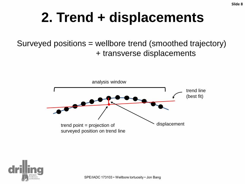
2. Trend + displacements
Slide 8
SPE/IADC 173103 • Wellbore tortuosity • Jon Bang
analysis window
trend line
(best fit)
displacement
Surveyed positions = wellbore trend (smoothed trajectory)
+ transverse displacements
trend point = projection of
surveyed position on trend line

Trend + displacements
Slide 9
SPE/IADC 173103 • Wellbore tortuosity • Jon Bang
High side Smoothed traj.
(≈ Along hole)
Lateral
High side
MD
Lateral

3. Effective diameter: Deff
Slide 10
SPE/IADC 173103 • Wellbore tortuosity • Jon Bang
Casing / wellbore ID = D0
Deff ≈ D0 / 2 Deff ≈ D0 / 6

Field case 1: Stuck casing, pump failure Slide 11
SPE/IADC 173103 • Wellbore tortuosity • Jon Bang
Dogleg
severity
T curve
Azimuth
Deff (colour coding)
displacements x 100

MWD dogleg
2
4
6
de
g/1
00
ft
Field case 2:
Pump placement
Slide 12
SPE/IADC 173103 • Wellbore tortuosity • Jon Bang
T curve
Deff curve
MWD incl and az
Wellbore shape,100 ft section
Pump
length:
100 ft
D0

Field case 3: Pump placement Slide 13
SPE/IADC 173103 • Wellbore tortuosity • Jon Bang
MWD dogleg suggests 7750-7950ft
MWD dogleg
Deff curve Maximum D for device length 124ft
is 3.1in, at 7880ft.
• Pump size and location were
reconsidered
• Nominal ID = 6.28inches
• ESP (124ft / 4in) to be installed
in horiz. section (below 7500ft)
Conclusions (1)
• New method for analysis of wellbore tortuosity • Three outputs: T, trend+displacements, Deff
• Single external parameter => device length
• Intuitive interpretation of results
• Improvement over existing Dogleg severity criterion
Slide 14
SPE/IADC 173103 • Wellbore tortuosity • Jon Bang
• Standard surveying procedure • High resolution data, survey interval ~1 ft
• Continuous gyro survey
Conclusions (2)
• Benefits • Normal (i.e., within spec.) operating conditions and power
consumption
• Reduced wear, reduced failure rate
• Reduced work-over frequency
• Reduced idle time and production losses
• Increased profit by reducing production costs
Slide 15
SPE/IADC 173103 • Wellbore tortuosity • Jon Bang
• Applications • Drilling: Evaluation of bottom-hole assembly (BHA) and
drilling process
• Completion, Production: Optimal locations for equipment
• Casing, completion equipment
• Electrical submersible pumps (ESP)
• Rod-guide, tubing sleeves for rod based surface pumps
Acknowledgments
John Weston, Gyrodata
Rob Shoup, Gyrodata
Gyrodata Inc.
SandRidge Energy
Slide 16
SPE/IADC 173103 • Wellbore tortuosity • Jon Bang
Thank you
Slide 17
SPE/IADC 173103 • Wellbore tortuosity • Jon Bang
Appendix (in case of questions)
Slide 18
SPE/IADC 173103 • Wellbore tortuosity • Jon Bang
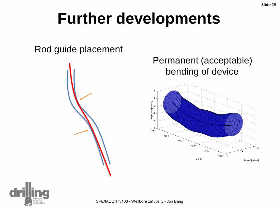
Further developments Slide 19
SPE/IADC 173103 • Wellbore tortuosity • Jon Bang
Rod guide placement
Permanent (acceptable)
bending of device
Slide 20
SPE/IADC 173103 • Wellbore tortuosity • Jon Bang
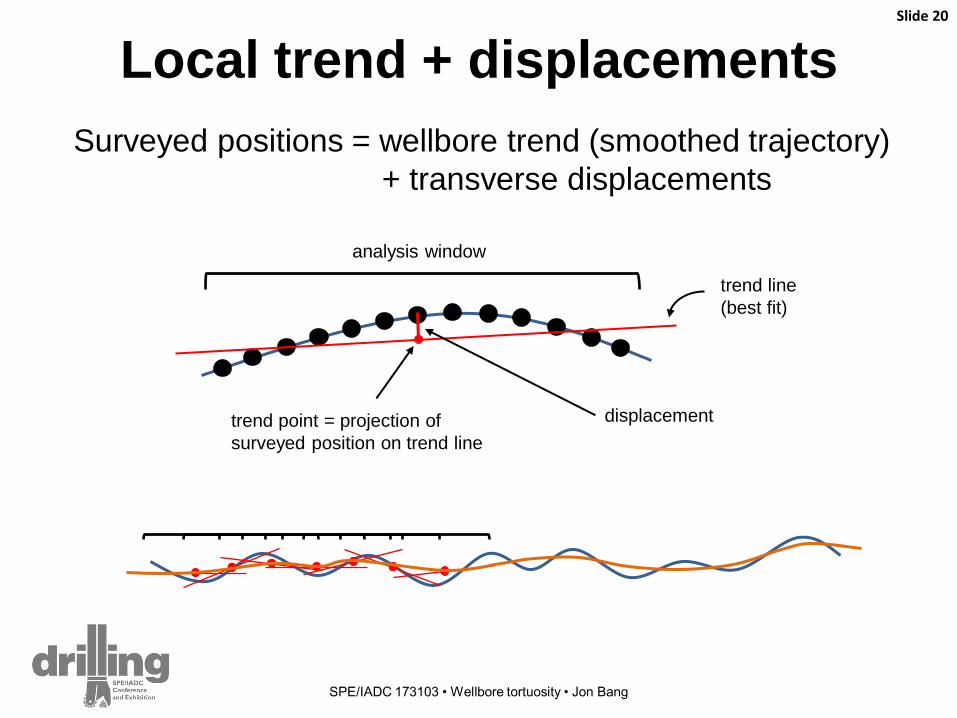
Local trend + displacements
analysis window
trend line
(best fit)
displacement
Surveyed positions = wellbore trend (smoothed trajectory)
+ transverse displacements
trend point = projection of
surveyed position on trend line
Slide 21
SPE/IADC 173103 • Wellbore tortuosity • Jon Bang
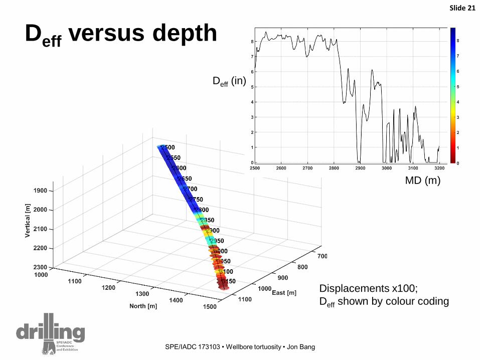
Deff versus depth
Displacements x100;
Deff shown by colour coding
MD (m)
Deff (in)
Slide 22
SPE/IADC 173103 • Wellbore tortuosity • Jon Bang
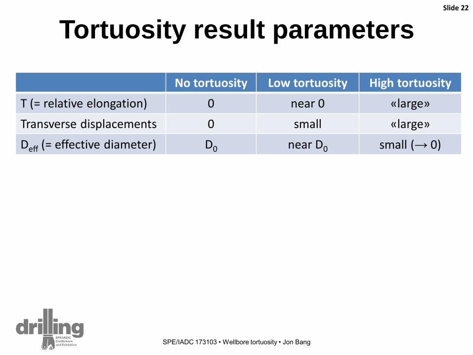
Tortuosity result parameters
No tortuosity Low tortuosity High tortuosity
T (= relative elongation) 0 near 0 «large»
Transverse displacements 0 small «large»
Deff (= effective diameter) D0 near D0 small (→ 0)
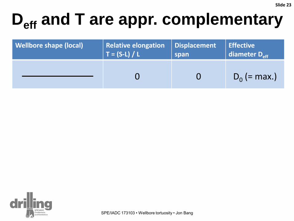
Wellbore shape (local) Relative elongation T = (S-L) / L
Displacement span
Effective diameter Deff
0
0
D0 (= max.)
small
small
near D0
large
large
small
large
small
near D0
Deff and T are appr. complementary Slide 23
SPE/IADC 173103 • Wellbore tortuosity • Jon Bang
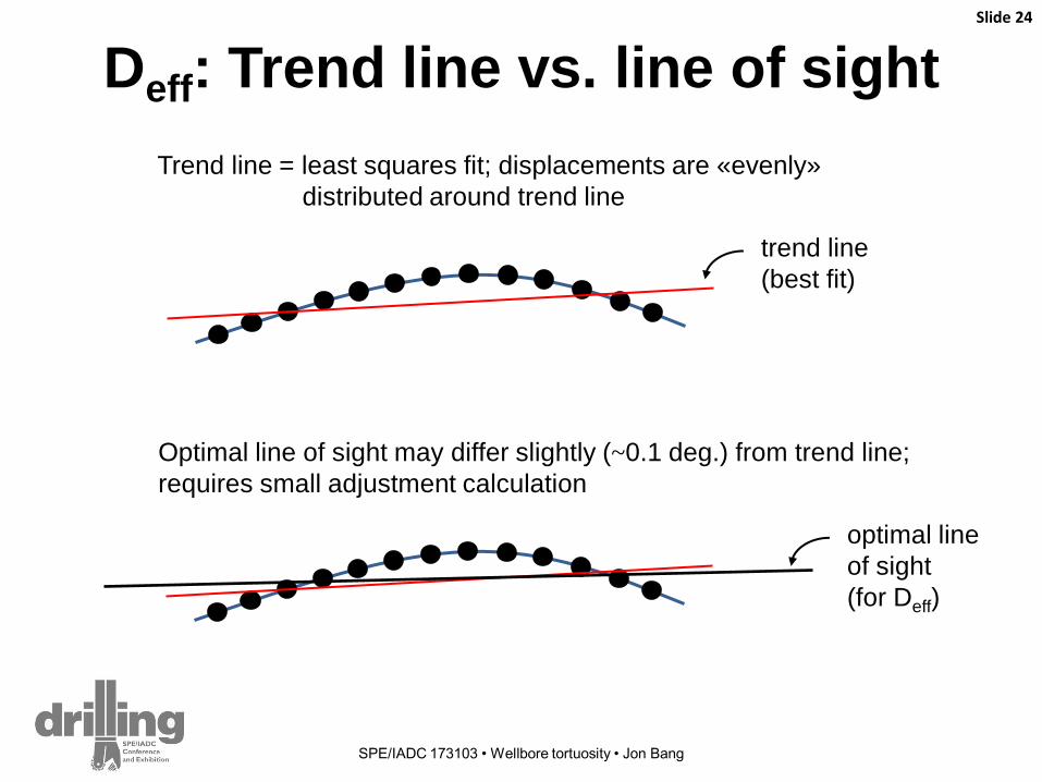
Deff: Trend line vs. line of sight Slide 24
SPE/IADC 173103 • Wellbore tortuosity • Jon Bang
trend line
(best fit)
Trend line = least squares fit; displacements are «evenly»
distributed around trend line
Optimal line of sight may differ slightly (~0.1 deg.) from trend line;
requires small adjustment calculation
optimal line
of sight
(for Deff)

Slide 25
SPE/IADC 173103 • Wellbore tortuosity • Jon Bang
Single external parameter: S
S = length of analysis window (along MD)
• Window must cover >~ 10 survey stations
• User-defined
• Interpretation: S = tortuosity length scale
≈ length of device