spectrodensitometer - x-rite · dear customer: congratulations! we at x-rite, incorporated are...
TRANSCRIPT

X-Rite® 938
Spectrodensitometer
Operation Manual


CAUTION: Operational hazard exists if AC adaptor other than X-Rite SE30-61 (115V) or SE30-62 (230V) is used. VORSICHT: Es besteht Betriebsgefahr bei der Verwendung von anderen Adapter als X-Rite SE30-61 (115 V) oder SE30-62 (230 V). AVISO: No use otro adaptador C.A. que no sea la pieza X-Rite SE30-61 (115V) o SE30-62 (230V), por el riesgo de mal funcionamiento del equipo. ATTENTION: Ne pas utiliser d'adaptateur autre que SE30-61 (115V) ou SE30-62 (230V) de X-Rite au risque de mauvais fonctionnement de l'appareil. AVVISO: Non usare un altro adattatore C.A. che non è del pezzo X-Rite SE30-61 (115V) o SE30-62 (230V), per il rischio di malfunzionamento dell'apparecchio. WARNING: Shielded interface cables must be used in order to maintain compliance with the desired FCC and European emission requirements. WARNING: This instrument is not for use in explosive environment. WARNUNG: Das Gerät soll in einer explosiven Umgebung NICHT verwendet werden. ADVERTENCIA: NO use este aparato en los ambientes explosivos. ATTENTION: Cet instrument NE DOIT PAS être utilisé dans un environnement explosif. AVVERTIMENTO: NON usare questo apparecchio in ambienti esplosivi. CE DECLARATION
Manufacturer's Name: X-Rite, Incorporated Manufacturer's Address: 3100 44th Street, S.W. U.S.A Grandville, Michigan 49418 Model Name: Spectrophotometer Model No.: 938 Directive(s) Conformance: EMC 89/336/EEC LVD 73/23/EEC 93/68/EEC NOTE: The device complies to the product specifications for the Low Voltage Directive when furnished with the 230VAC AC Adapter (X-Rite P/N SE30-62), and to UL Standards when furnished with the 115VAC AC Adapter (X-Rite P/N SE30-61).

USE ONLY: AA NICad batteries that are 600/700 mAh rated, six required. Other types may burst causing personal injury. ACHTUNG: Verwenden Sie nur AA Nicad Akkus von 600/700 mAh (Milliamperestunde) Nennstrom (6 Stück erforderlich). Mit anderen Akkus läuft die Gefahr von Explosion und Verletzung. ATENCION: Use solamente las pilas de AA NiCad (se requiere seis) con condiciones de funcionamiento normales 600/700 mAh (horas miliamperios). Es posible que los otros tipos puedan estallar y causar daños corporales. ATTENTION: Utiliser seulement les batteries NICad à courant nominal de 600mAh (milliampère-heure) (6 pièces nécessaire). Il y a danger d'explosion et de blessures avec les autres types. ATTENZIONE: Usare solamente gli accumulatori al AA NiCad (si richiede sei) con le condizioni di funzionamento normali 600/700mAh (ore milliamperi). E possibile che altri tipi possano scoppiare e causare danno personale.
FCC (Federal Communications Commission Notice) This equipment has been tested and found to comply with the limits for a Class A digital device, pursuant to Part 15 of the FCC Rules. These limits are designed to provide reasonable protection against harmful interference when the equipment is operated in a commercial environment. This equipment generates, uses, and can radiate radio frequency energy and, if not installed and used in accordance with the instruction manual, may cause harmful interference to radio communications. Operation of this equipment in a residential area is likely to cause harmful interference in which case the user will be required to correct the interference at his own expense. Industry Canada Compliance Statement This Class A digital apparatus complies with Canadian ICES-003. Cet appareil numérique de la classe A est conforme à la norme NMB-003 du Canada.
The Manufacturer: X-Rite, Incorporated Der Hersteller: 3100 44th Street, S.W. El fabricante: Grandville, Michigan 49418 Le fabricant: Il fabbricante: Declares that: Spectrodensitometer gibt bekannt: 938 advierte que: avertit que: avverte che: is not intended to be connected to a public telecommunications network. nicht an ein öffentliches Telekommunikations-Netzwerk angeschlossen werden soll. no debe ser conectado a redes de telecomunicaciones públicas. ne doit pas être relié à un réseau de télécommunications publique. non deve essere connettuto a reti di telecomunicazioni pubblici.

Dear Customer:Congratulations! We at X-Rite, Incorporated are proud to present you
with an X-Rite Color Measurement Instrument. This instrument representsthe very latest in microcontrollers, integrated circuits, fiber optics, anddisplay technology. As a result, your X-Rite 938 is a rugged and reliableinstrument whose performance and design exhibit the qualities of a finelyengineered instrument, which is not surpassed.
To fully appreciate and protect your investment, we suggest that youtake the necessary time to read and fully understand this manual. Asalways, X-Rite stands behind your unit with a one year limited warranty,and a dedicated service organization. If the need arises, please don’thesitate to call us.
Thank you for your trust and confidence.
X-Rite, Incorporated
i
Table of ContentsOpening Letter . . . . . . . . . . . . . . . . . . . . . . . . . . . . . . . . . . . . . . . . . . . . . . . . . . . . . . . . . . . . . iProprietary Notice . . . . . . . . . . . . . . . . . . . . . . . . . . . . . . . . . . . . . . . . . . . . . . . . . . . . . . . . . . ivLimited Warranty . . . . . . . . . . . . . . . . . . . . . . . . . . . . . . . . . . . . . . . . . . . . . . . . . . . . . . . . . . . ivGeneral Description . . . . . . . . . . . . . . . . . . . . . . . . . . . . . . . . . . . . . . . . . . . . . . . . . . . . . . . . . vUser Interface . . . . . . . . . . . . . . . . . . . . . . . . . . . . . . . . . . . . . . . . . . . . . . . . . . . . . . . . . . . . . . viiWhat To Do First! . . . . . . . . . . . . . . . . . . . . . . . . . . . . . . . . . . . . . . . . . . . . . . . . . . . . . . . . . . viii
1. Getting Started. . . . . . . . . . . . . . . . . . . . . . . . . . . . . . . . . . . . . . . . . . . 11.1 Packaging Check list . . . . . . . . . . . . . . . . . . . . . . . . . . . . . . . . . . . . 11.2 Shoe Lock. . . . . . . . . . . . . . . . . . . . . . . . . . . . . . . . . . . . . . . . . . . . . 31.3 Battery Charging . . . . . . . . . . . . . . . . . . . . . . . . . . . . . . . . . . . . . . . 41.4 Applying Power . . . . . . . . . . . . . . . . . . . . . . . . . . . . . . . . . . . . . . . . 4
2. Positioning Techniques . . . . . . . . . . . . . . . . . . . . . . . . . . . . . . . . . . . . 5
3. Colorimetric Operation . . . . . . . . . . . . . . . . . . . . . . . . . . . . . . . . . . . 73.1 Keyswitch Descriptions . . . . . . . . . . . . . . . . . . . . . . . . . . . . . . . . . . 73.2 Function Selection . . . . . . . . . . . . . . . . . . . . . . . . . . . . . . . . . . . . . . 83.3 Illuminant/Observer Selection . . . . . . . . . . . . . . . . . . . . . . . . . . . . . 103.4 Absolute Measurement . . . . . . . . . . . . . . . . . . . . . . . . . . . . . . . . . . 123.5 Difference Measurement . . . . . . . . . . . . . . . . . . . . . . . . . . . . . . . . . 13
3.5.1 Entry of Reference Values . . . . . . . . . . . . . . . . . . . . . . . . . . . . . 143.5.2 Taking A Difference Measurement . . . . . . . . . . . . . . . . . . . . . . 18
3.6 CMC Difference Operation . . . . . . . . . . . . . . . . . . . . . . . . . . . . . . . 19
4. Densitometric Operation . . . . . . . . . . . . . . . . . . . . . . . . . . . . . . . . . . 214.1 Keyswitch Description. . . . . . . . . . . . . . . . . . . . . . . . . . . . . . . . . . . 214.2 Function Selection . . . . . . . . . . . . . . . . . . . . . . . . . . . . . . . . . . . . . . 224.3 Response Selection. . . . . . . . . . . . . . . . . . . . . . . . . . . . . . . . . . . . . . 234.4 Density Operation . . . . . . . . . . . . . . . . . . . . . . . . . . . . . . . . . . . . . . 254.5 Dot Operation. . . . . . . . . . . . . . . . . . . . . . . . . . . . . . . . . . . . . . . . . . 264.6 Trap Operation . . . . . . . . . . . . . . . . . . . . . . . . . . . . . . . . . . . . . . . . . 294.7 Print Contrast Operation . . . . . . . . . . . . . . . . . . . . . . . . . . . . . . . . . 324.8 Hue Error/Grayness (or Saturation) Operation . . . . . . . . . . . . . . . . 344.9 Brightness Operation . . . . . . . . . . . . . . . . . . . . . . . . . . . . . . . . . . . . 364.10Spectral Operation . . . . . . . . . . . . . . . . . . . . . . . . . . . . . . . . . . . . . . 37
5. Measurement Averaging Procedure . . . . . . . . . . . . . . . . . . . . . . . . . 41
6. Store Data Operation . . . . . . . . . . . . . . . . . . . . . . . . . . . . . . . . . . . . . 43
7. Calibration . . . . . . . . . . . . . . . . . . . . . . . . . . . . . . . . . . . . . . . . . . . . . . 467.1 Positioning the Instrument on the X-Rite
Calibration Standard . . . . . . . . . . . . . . . . . . . . . . . . . . . . . . . . . . . . 477.2 Calibrating to the White Standard. . . . . . . . . . . . . . . . . . . . . . . . . . 50
8. Setting System Parameters. . . . . . . . . . . . . . . . . . . . . . . . . . . . . . . . . 548.1 Averaging . . . . . . . . . . . . . . . . . . . . . . . . . . . . . . . . . . . . . . . . . . . . . 548.2 Colorimetric Operation Parameters . . . . . . . . . . . . . . . . . . . . . . . . . 568.3 Densitometric Operation Parameters. . . . . . . . . . . . . . . . . . . . . . . . 588.4 RS232 I/O Parameters . . . . . . . . . . . . . . . . . . . . . . . . . . . . . . . . . . . 608.5 Format Output Parameters . . . . . . . . . . . . . . . . . . . . . . . . . . . . . . . . 62
ii

9. Display Messages. . . . . . . . . . . . . . . . . . . . . . . . . . . . . . . . . . . . . . . . . . 65
10. Printing Data . . . . . . . . . . . . . . . . . . . . . . . . . . . . . . . . . . . . . . . . . . . . 68
11. Changing Apertures . . . . . . . . . . . . . . . . . . . . . . . . . . . . . . . . . . . . . . 72
12. Maintenance. . . . . . . . . . . . . . . . . . . . . . . . . . . . . . . . . . . . . . . . . . . . . 7412.1 Troubleshooting. . . . . . . . . . . . . . . . . . . . . . . . . . . . . . . . . . . . . . . . 7412.2 Optics Cleaning . . . . . . . . . . . . . . . . . . . . . . . . . . . . . . . . . . . . . . . . 7512.3 Battery Replacement . . . . . . . . . . . . . . . . . . . . . . . . . . . . . . . . . . . . 7612.4 Target Window Replacement . . . . . . . . . . . . . . . . . . . . . . . . . . . . . 7712.5 Lamp Replacement . . . . . . . . . . . . . . . . . . . . . . . . . . . . . . . . . . . . . 78
Appendix. . . . . . . . . . . . . . . . . . . . . . . . . . . . . . . . . . . . . . . . . . . . . . . . . . 79A1 - Specifications . . . . . . . . . . . . . . . . . . . . . . . . . . . . . . . . . . . . . . . . . 79A2 - Optional Accessories . . . . . . . . . . . . . . . . . . . . . . . . . . . . . . . . . . . 81A3 - Factory Presets . . . . . . . . . . . . . . . . . . . . . . . . . . . . . . . . . . . . . . . . 82A4 - Spectrophotometer Stand . . . . . . . . . . . . . . . . . . . . . . . . . . . . . . . . 83A5 - Color Check . . . . . . . . . . . . . . . . . . . . . . . . . . . . . . . . . . . . . . . . . . 84
Copyright 2002 by X-Rite, Incorporated "ALL RIGHTS RESERVED"
Trademark Recognition:IBM is a registered trademark of International Business Machines Corp.
Macintosh® is a registered trademark of Apple Computer, Inc.
All other logos, product names, and trademarks mentioned are the property of their respective holders.
iii
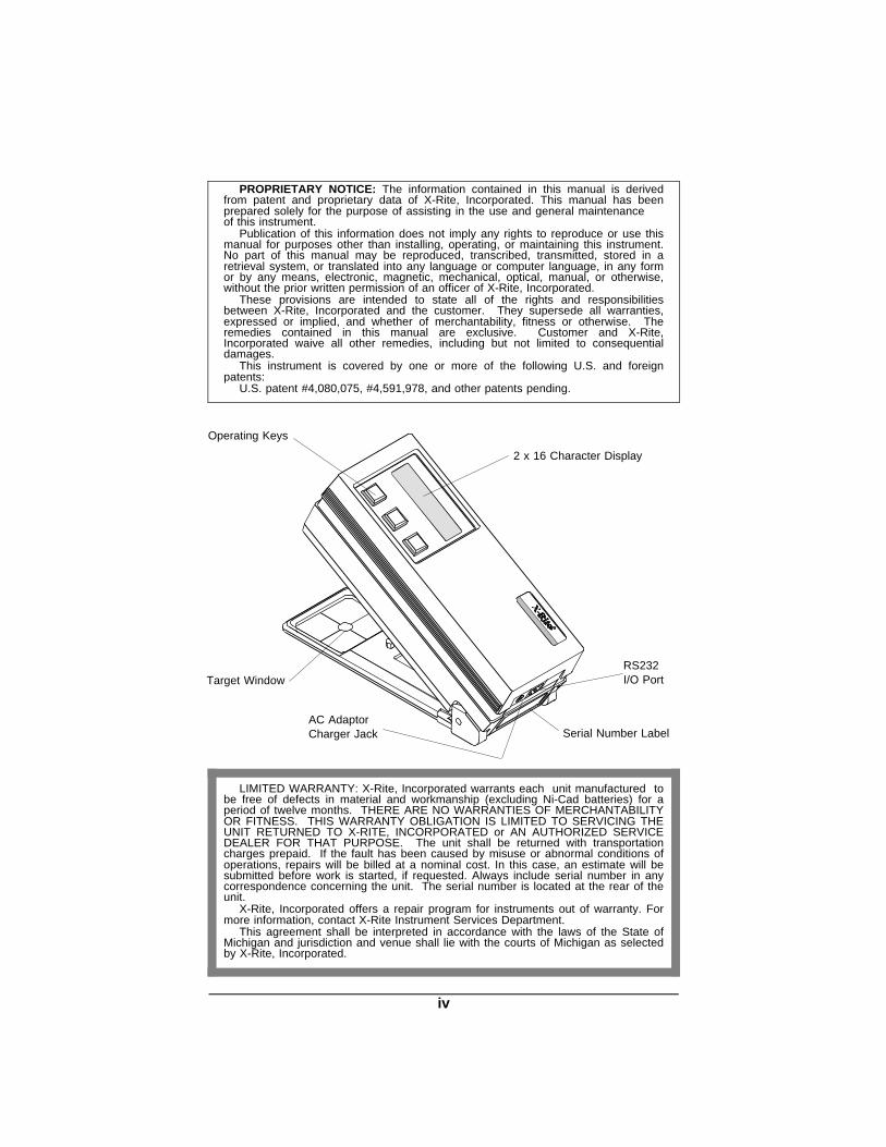
Operating Keys
2 x 16 Character Display
Target Window
AC AdaptorCharger Jack
RS232I/O Port
PROPRIETARY NOTICE: The information contained in this manual is derivedfrom patent and proprietary data of X-Rite, Incorporated. This manual has beenprepared solely for the purpose of assisting in the use and general maintenanceof this instrument.
Publication of this information does not imply any rights to reproduce or use thismanual for purposes other than installing, operating, or maintaining this instrument.No part of this manual may be reproduced, transcribed, transmitted, stored in aretrieval system, or translated into any language or computer language, in any formor by any means, electronic, magnetic, mechanical, optical, manual, or otherwise,without the prior written permission of an officer of X-Rite, Incorporated.
These provisions are intended to state all of the rights and responsibilitiesbetween X-Rite, Incorporated and the customer. They supersede all warranties,expressed or implied, and whether of merchantability, fitness or otherwise. Theremedies contained in this manual are exclusive. Customer and X-Rite,Incorporated waive all other remedies, including but not limited to consequentialdamages.
This instrument is covered by one or more of the following U.S. and foreignpatents:
U.S. patent #4,080,075, #4,591,978, and other patents pending.
Serial Number Label
LIMITED WARRANTY: X-Rite, Incorporated warrants each unit manufactured tobe free of defects in material and workmanship (excluding Ni-Cad batteries) for aperiod of twelve months. THERE ARE NO WARRANTIES OF MERCHANTABILITYOR FITNESS. THIS WARRANTY OBLIGATION IS LIMITED TO SERVICING THEUNIT RETURNED TO X-RITE, INCORPORATED or AN AUTHORIZED SERVICEDEALER FOR THAT PURPOSE. The unit shall be returned with transportationcharges prepaid. If the fault has been caused by misuse or abnormal conditions ofoperations, repairs will be billed at a nominal cost. In this case, an estimate will besubmitted before work is started, if requested. Always include serial number in anycorrespondence concerning the unit. The serial number is located at the rear of theunit.
X-Rite, Incorporated offers a repair program for instruments out of warranty. Formore information, contact X-Rite Instrument Services Department.
This agreement shall be interpreted in accordance with the laws of the State ofMichigan and jurisdiction and venue shall lie with the courts of Michigan as selectedby X-Rite, Incorporated.
iv
General Description The 938 measures spectral reflectance from 400nm to 700nm in 20nm
intervals. It has a 0° illumination angle, a 45° viewing angle, and features adual-beam, single light pulse compensation method to insure accuracy.
The 938 calculates colorimetric, densitometric, and spectrophotometric data.The 938 displays colorimetric & densitometric data, and can output (to aprinter or computer) colorimetric, densitometric, and spectral data. An optionalsoftware package (e.g., SpectroStart) can collect, sort, view and analyzeL*a*b*, L*C*h°, and spectral data using an IBM compatible computer.
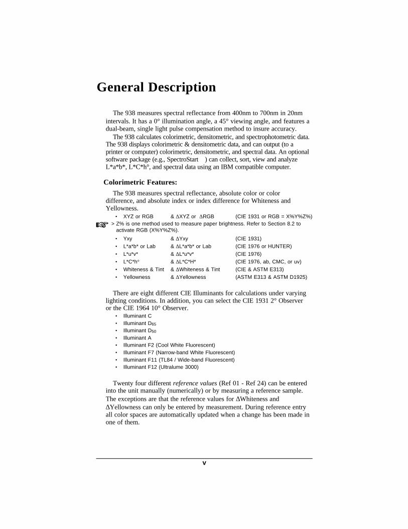
Colorimetric Features:The 938 measures spectral reflectance, absolute color or color
difference, and absolute index or index difference for Whiteness andYellowness.
• XYZ or RGB & ∆XYZ or ∆RGB (CIE 1931 or RGB = X%Y%Z%) > Z% is one method used to measure paper brightness. Refer to Section 8.2 to
activate RGB (X%Y%Z%).
• Yxy & ∆Yxy (CIE 1931)
• L*a*b* or Lab & ∆L*a*b* or Lab (CIE 1976 or HUNTER)
• L*u*v* & ∆L*u*v* (CIE 1976) • L*C*h° & ∆L*C*H* (CIE 1976, ab, CMC, or uv)
• Whiteness & Tint & ∆Whiteness & Tint (CIE & ASTM E313)
• Yellowness & ∆Yellowness (ASTM E313 & ASTM D1925)
There are eight different CIE Illuminants for calculations under varyinglighting conditions. In addition, you can select the CIE 1931 2° Observeror the CIE 1964 10° Observer.
• Illuminant C • Illuminant D65 • Illuminant D50
• Illuminant A • Illuminant F2 (Cool White Fluorescent) • Illuminant F7 (Narrow-band White Fluorescent) • Illuminant F11 (TL84 / Wide-band Fluorescent) • Illuminant F12 (Ultralume 3000)
Twenty four different reference values (Ref 01 - Ref 24) can be entered
into the unit manually (numerically) or by measuring a reference sample.The exceptions are that the reference values for ∆Whiteness and∆Yellowness can only be entered by measurement. During reference entryall color spaces are automatically updated when a change has been made inone of them.
v

The instrument can function as a color difference meter. By entering in yourreference (by measurement or numerically), the unit will indicate the amount ofdifference between the reference and the measured sample.
CMC difference provides a single numeric value (∆ECMC) which describes thecolor difference between a sample and a standard.
Densitometric Features:The 938 measures Density, Dot, Trap, Print Contrast, Hue Error/Grayness (or
Hue Error/Saturation), Brightness, and λDensity.• DEN & DEN-Paper • DOT w/Murray-Davies or Yule-Nielson formula • TRAP w/Preucil, Brunner, or Newsprint formula • PC & PC-Paper • H/G & H/G-Paper or H/S & H/S-Paper • BRIGHTNESS
• λDEN or λDOT or λREFL
The 938 has four different responses that can be selected.• RESPONSE T • RESPONSE E • RESPONSE I • RESPONSE A
> Refer to Section 4.3 for additional information on response selection.
Additional Features:The store data feature allows the unit to store up to five hundred measurements
for transferring to a printer or computer (via RS232) at a later time. The averaging feature allows the unit to make several measurements from the
same and/or different locations on a sample or reference. This will allow for a betteroverall average of a color.
The unit is powered by six AA rechargeable batteries, or by the ACadaptor/charger provided. Additionally, the unit retains calibration and referencevalues when turned off, or if the Ni-Cad batteries are discharged.
vi

User Interface
This section will familiarize you with the typographical conventions,display functions, and general terms used in this manual.
• In the text portion of this manual the 938 keys are shown withbrackets on both sides and in boldface. Ex., [FUNCTION], [ILLUM],and [DIF].
• When a key is to be momentarily pressed, the statement "press" willbe used. Ex., Press [FUNCTION].
• When a key is to be held depressed until another action occurs, thestatement "hold down" will be used. Ex., Hold down [ILLUM] until"SELECT ILLUMINANT" is displayed.
• Information that will appear in thedisplay window will be shown withquotation marks on each side and inboldface. Ex., "SELECT ILLUMINANT"
• The symbols ▼ and ▲ represent theblue and red arrows on the 938. Incalibration and reference value entry thearrows indicate which direction a valuecan be changed. Holding [DIF]depressed and pressing [▼] decreasesthe value and [▲] increases the value.
• The term "cursor" represents a blackrectangle that will blink next to orover a value or function in thedisplay. In most cases it means thatvalue is active and can be altered viathe [▼] and [▲] keys.
• A "hand" indicates important notes and possibleoperations that need to be performed before thenormal operation.
• When a procedure is continued on the next page anarrow will appear in the bottom right hand corner ofthe page.
• Illuminant/observer combinations are expressed by special notations(Ex., D65
2 indicates illuminant D, 6500 Κ, and 2° observer).
FUNCTION ILLUM DIF
CAL
SELECTILLUMINANT
FUNCTION ILLUM DIF
CAL
X 4 . 1 2Y 2 . 8 7 Z 2 . 4 1
C2X Y Z
WHTy . 3 1 8 1
C 2
x . 3 0 9 0Y 8 5 . 5 5
CURSOR
vii

What To Do First!
See how to unlock the shoe and charge the batteries...read Section 1 - Getting Started.
See how the positioning of the instrument during measurementaffects the reading...read Section 2 - Positioning Techniques.
Calibrate your instrument...read Section 7 - Calibration.
Setup your instrument. You can set the operating parameters,RS232 parameters, and format output parameters of your unit.Remember, you can lock out of the display any function you donot want to use...read Section 8 - Setting System Parameters.
Learn the basic functions...read Sections 3 & 4 - Colorimetric &Densitometric Operation.
viii

1. Getting Started
1.1 Packaging Check List
After removing the instrument from the shipping carton, inspect forpossible damage. If any damage is noted, contact the transportationcompany immediately. Do nothing more until the carrier’s agent hasinspected the damage.
If damage is not evident, check and make sure that all items areincluded (Refer to the parts list below, and following page for thepackaging illustration).
Your unit was packaged in a specially designed carton to assureagainst damage. If reshipment is necessary, the instrument should bepackaged in the original carton. If the original carton is not available, anew one can be obtained from X-Rite Inc. Refer to the packaging drawingon the following page (items 1, and 2).
PACKAGING PARTS LIST
1

PACKAGING
2

1.2 Shoe Lock
The shoe can be locked next to the housing for ease of storage.
Unlocking Shoe1. Hold shoe [1] against unit.
2. Slide black lock button [2] on bottom of unit towards the back until itstops, then slowly release shoe [1].
Locking Shoe1. Hold shoe [1] against unit.2. Slide black lock button [2] towards the front until it stops, then release
shoe [1].
[1]
[2]
3

1.3 Battery Charging
> THE UNIT SHOULD BE CHARGED BEFORE USE. The unit can be operatedwhile the batteries are being charged. Before using make sure the voltageindicated on the AC adaptor complies with the AC line voltage in your area. Ifnot contact your X-Rite dealer.
> The unit should be fully charged in 14 hours. Note: If your unit has not beenused for several weeks recharge for approximately 24 hours.
> Charging the batteries for less than 14 hours will reduce the operating time ofthe unit.
> The best method to obtain the maximum battery life is to:- Always run the unit down to the point where the "BATTERIES LOW" message
is displayed. Then charge the unit before the next message "CHARGEBATTERIES" is displayed.
- Leaving the unit plugged into the AC wall outlet for extended periods of time(over 48 hours) may shorten the battery life.
- If you are going to store the unit for an extended period of time (over 6months) you should remove the Ni-Cad batteries from the unit.
1. Plug the small connector end of the adaptor into back of unit.2. Plug the adaptor into AC wall outlet.
1.4 Applying Power
1. During battery operation power is applied automatically when ameasurement is taken or if a key is pressed. It automatically shuts off(within 45 seconds) if no keys are pressed or no further measurementsare taken. The unit will not automatically shut off if the AC adaptor isconnected.
> This unit retains calibration, reference values, and all other data when the unitturns off after 45 seconds of non-use (in battery operation), or if the Ni-Cadbatteries are discharged.
SMALLCONNECTOR
ADAPTOR
WALL OUTLET
4

2. Positioning Techniques
INSTRUMENTThe variety of items that the 938 can measure is almost endless.
However, in order to obtain accurate and repeatable measurements, thebottom of the shoe must be:
• Parallel with the surface to be measured if the surface is flat. • Tangent to the surface to be measured if the surface is curved.
The reason for this is that any movement during measurement can causethe reading to vary. To obtain the most accurate and repeatablemeasurements, there are a few guide rules you can follow.
If the item to be measured is smaller than the shoe, you may want tomake a platform (the same height of the item) for the instrument to sit on.If the item to measure is curved, you may want to make a jig for the itemto rest in.
Shown below and on the next page are some examples of methods usedto accomplish this. Example 1 shows a platform for measuring a paintchip. Example 2 shows a jig being used for measuring a small knob.Example 3 shows a jig being used to measure a cup.
> A Spectrophotometer Stand is available from X-Rite (P/N 968-80). The stand canhold objects that are a maximum of 4" inches in width, or 2" to the center of theobject. Refer to Appendix A-4 for further information about this mounting fixture.
Example 1- Measuring a Paint Chip
INCORRECTCORRECT
Paint Chip Platform
Example 2- Measuring a Small Knob
KnobJig
CORRECT
5

TARGET WINDOWWhen measuring, center target window opening over spot to read using
the cross hairs for alignment purposes. The 938 is shipped from the factory with 4mm optics installed.
Although the illuminating spot produced by the instrument is 4mm, theactual target window opening is 6mm. Therefore, proper positioning underthe target window opening is important when measuring 4mm size patches.Example 4 shows the target window placement on a 4mm size patch of acolor bar.
Example 3 - Measuring a Coffee Cup
CORRECT
Coffee Cup
Jig
Example 4 - Target Window Positioning
Target WindowOpening
Cross Hair Illuminanting Spot from the Unit
Color Bar
ShoeColor Bar PatchCentered inTarget Window
6

3. Colorimetric Operation
3.1 Key Descriptions
[FUNCTION]/[▼]
• Selects the function that will be used for measurement. Eachmomentary depression will cause the display to page through XYZ,Yxy, L*a*b*, L*u*v*, L*C*h°, Whiteness, & Yellowness.
• Decreases numeric values when used with the [DIF] key during entryof reference or calibration values.
• Selects Calibration when pressed with [ILLUM] key.
• Selects various steps when in system setup procedures.
[ILLUM]/[▲]
• When held depressed activates illuminant/observer selection,thereafter, momentary depressions select the illuminant to be used.The available illuminants are:
Note: the [DIF] key selects the Observer (CIE 1931 2° or CIE 196410°) to be used.
• Increases numeric values when used with [DIF] key during entry ofreference or calibration values.
• Displays the reference number when pressed momentarily. • Selects Calibrate when pressed with the [FUNCTION] key.
[DIF]/[▼▲]
• When at function level, toggles Delta (∆) On and Off with eachdepression. Delta being the difference mode.
• Decreases reference or calibration values when used with the[FUNCTION] key.
• Increases numeric values when used with the [ILLUM] key.
FUNCTION ILLUM DIF
CAL
C A
F7F2 F12F11
D 65 D50
7

3.2 Function Selection
Each momentary depression of [FUNCTION] will sequentially pagethrough the available functions: CIE XYZ (or RGB), Yxy, L*a*b* (or LabHunter), L*u*v*, abL*C*h° (or uvL*C*h°), Whiteness, & Yellowness.
Functions can be turned on, off, or changed in Colorimetric OperationParameters, Section 8.2.
If ∆ is active the following is displayed
CAL
PRESS TO SELECTNEXT FUNCTION
RGB
L 2 3 . 4 8.a + 1 8 . 5 9.
b + 8 . 7 5.C2.
L a b..OR
Lab(Hunter)
L 2 3 . 4 5.
C 2 0 . 7 8.
h 2 5 . 7 9C2L C h
. .ab
OR
v L C h. .
L 1 2 . 3 3.
v + 6 . 8 9.
u + 2 2 . 4 6. C2.
L u v . .
+ 8 7 . 9 7Y + 3 3 . 5 6eC 2YELY d
W 9 7 . 8 7 T - 1 1 5 . 8W - 1 . 3 7eC2W H T
+
L 2 3 . 4 5.
C 2 0 . 7 8. H 2 5 . 7 9
C2L C H. . .
+ +
L 1 2 . 3 3.
u + 2 2 . 4 6.
v + 6 . 8 9C2.
L u v . . +
a + 1 8 . 5 9.
b + 8 . 7 5C2.
L a b.. .
+L 2 3 . 4 8OR
Lab(Hunter)
X 4 . 1 2Y 2 . 8 7 Z 2 . 4 1
C2X Y Z+
++
OR
RGB
Y 3 . 2 4x .2 6 7 8 y .3 5 9 8
C2Y x y +
++
+ 8 7 . 9 7Y + 3 3 . 5 6eC2YELY d
W 9 7 . 8 7 T - 1 1 5 . 8W - 1 . 3 7eC 2W H T
Y 3 . 2 4x .2 6 7 8 y .3 5 9 8
C2Y x y
FUNCTION ILLUM DIF
X 4 . 1 2Y 2 . 8 7 Z 2 . 4 1
C2
OR
OR
u L C HCCCE
X Y Z
8

> The illuminant/observer will not be displayed in the difference mode duringoperation of that function. It is only displayed during function selection.
> ∆ E will be displayed in place of ∆ L*a*b*, ∆ L*u*v*, and ∆ L*C*H* duringdifference operation.
X 4 .1 2Y 2 . 8 7 Z 2 .4 1
Y 3 .2 4x . 2 8 9 0 y .3 6 4 5
a + 1 8 . 5 9.
b + 8 . 7 5
L 1 2 . 3 3.
u + 2 2 . 4 6.
v + 6 . 8 9
L 2 3 . 4 5.
C 2 0 . 7 8. H 2 5 . 7 9
Y x y
W 9 7 . 8 7 T - 1 1 5 . 8W - 1 . 3 7eW H T
Y E L Y + 3 3 .5 6e Yd + 8 7 .9 7
X Y Z
+
+
.L 2 3 . 4 8
+
E 41.89
E 23.67
E 15.98
DELTA E
ILLUMINANTNOT DISPLAYED
++
+
+
++
+
OR
EC
9

3.3 Illuminant/Observer Selection
There are eight different illuminants and two observers to choosefrom.
1) To enable illuminant selection:Hold down [ILLUM] until"SELECT ILLUMINANT" isdisplayed.
2) The active illuminant &observer are displayed.
Press [ILLUM] to select adifferent illuminant.
Note: Illuminant F2 represents a coolwhite fluorescent lamp.
Illuminant F7 represents abroad-band daylight fluorescent lamp.
Illuminant F11 represents anarrow-band white fluorescent lamp(or illuminant TL84).
Illuminant F12 represents Ultralume3000.
3) Press [DIF] to select a differentobserver.
FUNCTION ILLUM DIF
CAL
SELECTILLUMINANT
X 4 . 1 2Y 2 . 8 7 Z 2 . 4 1
C 2X Y Z
Hold
FUNCTION ILLUM DIF
CAL
C2
illmexit obs
C10
Press
FUNCTION ILLUM DIF
CAL
C2
illmexit obs
Ultralume2F12
TL842F11
broad bandF7 2
cool whiteF2 2
A2
50D 2
65D 2
Press
10

4) To exit press [FUNCTION].
When "Function Key" ispressed, the instrument willautomatically convert the storedspectral references (if any) totristimulus for the differentillum/obs selected. The unit willalso ask if you would like thereferences to be cleared. If youdo not want the referencescleared (or you do not have anyentered), disregard theprocedure below.
Clearing References
The "Clear Reference" functionis useful if the Illum/Obs isbeing changed often, and manyreferences exist in theinstrument that are not beingused. This will enable theoperator to speed up the time ittakes the instrument torecalculate to a differentillum/obs.
Press [DIF] to enter clearreference function. Afterthe "Dif Key" is pressed "CLEARREFERENCES ↓ NO YES↓ " isdisplayed. Press [DIF] to clearor [FUNCTION] not to clear.
> You must press the "Dif" key whilethe unit is recalculating thereferences to activate this function.
> If the clearing procedure is carriedout, all references (measured &numerically entered) will beremoved.
> Refer to Section 3.5 for a moredetailed explanation on measuredand numerically enteredreferences.
FUNCTION ILLUM DIF
CAL
C10
Press
obsillmexit
UPDATING REFS # 1-24CLEAR REFS
X 4 . 0 8Y 2 . 8 1 Z 2 . 3 7
C10X Y Z
11

3.4 Absolute Measurements
The 938 can perform absolute measurement in XYZ (RGB), Yxy,L*a*b*, L*u*v*, L*C*h°, Whiteness, & Yellowness.
> Helpful Hint: If you are going to measure something like a textile, you willreceive better results if you use the averaging function (see Section 8.1). Also,while measuring a textile, take several measurements in a circular format.
> If the ∆ is displayed, press [DIF] to activate absolute mode.> If the desired illuminant is not displayed refer to Section 3.3.
1) Press [FUNCTION] to selectdesired measurement space.
2) Center the target window overthe area to be measured.
3) Lower unit to target windowand firmly hold compressed."READING XYZ C2" (i.e., theselected function & theillum/obs) will momentarily bedisplayed, and then the data. Release unit after data isdisplayed.
4) The display will show theabsolute values for XYZ.
FUNCTION ILLUM DIFCAL
Press
X 4 . 1 2Y 2 . 8 7 Z 2 . 4 1
C2X Y Z
X Y Z X 1 . 2 4Y 3 . 3 6 Z 4 . 1 8
FUNCTION ILLUMINANT X VALUE
Y VALUE Z VALUE
C2
READING XYZ
X 1 . 2 4Y 3 . 3 6 Z 4 . 1 8
X Y Z
2C
2C
TARGET WINDOW
12

3.5 Difference Measurement
The 938 can measure the difference between a sample color and areference. In order to measure these differences the reference must firstbe entered into memory. There are 24 different locations to storereferences. The reference can be entered numerically using the key pad,or by measuring the reference color.
> The ∆Whiteness and ∆Yellowness reference color can only be entered bymeasurement.
Reference (Measurement)Measured references are stored spectrally and the tristimulus values
are recalculated each time a different illum/obs is selected. As long asreferences are measured, the instrument can automatically convert thespectral data to allow for viewing of difference measurements undervarious illum/obs sets.
Reference (Numeric)Numerically entered references are saved with the selected illum/obs.
A total of 7 sets of numerically entered tristimulus values (with differentillum/obs) can be stored in each reference location.
If a different illum/obs is selected and no numerically enteredreference supports that illum/obs, the instrument will turn "OFF" thatreference location.
The instrument can not recalculate to a different illum/obs if it wasnot previously entered during numeric reference entry.
Operation ModeThe instrument can be set to operate in an automatic mode, where it
will automatically select the closest reference; or in manual mode, whereyou have to manually select the reference locations you want to use.Refer to Section 8.2, for information on selecting manual or automaticreference operation.
In automatic mode, theinstrument will select thereference that is closest to themeasured color. If by somechance it is not the correctreference, simply press the[ILLUM] key twice and the unitwill select the next closestreference.
In manual mode, you mustmanually select the reference.Once you have selected areference, that reference will beused until you select a different reference.
FUNCTION ILLUM DIF
CAL
X 4 . 1 2Y 2 . 8 7 Z 2 . 4 1
C2X Y Z
PRESS TO TOGGLE DIFFERENCE (DELTA) ON & OFF
Y 2 . 8 7 Z + 2 . 4 1X Y Z+
DELTA SIGN PLUS SIGN
DELTA ON
DELTA OFF
+X 4 . 1 2
13

To activate the Difference mode, press [DIF] and the ∆ sign will appearin the display. The ∆Functions will have a "+ " sign in front of them forpositive values instead of being implied as in the absolute function.
> ∆L*a*b*, ∆L*u*v*, & ∆L*C*H* show ∆E in function location.> When entering references with any illuminant other than C2, Yellowness and
Whiteness (per ASTM E313) are not calculable.> Once a reference has been set, changing between CIE Lab or Hunter Lab; Lch
(ab) or Lch (uv); and XYZ or X%Y%Z%, the references will not be automaticallyadjusted.
Note: You can set all reference locations to OFF by: •Activating difference mode.•Hold down [DIF] until reference entry is activated, thensimultaneously press [ILLUM] and [FUNCTION].
> Ref 1 defaults to ON if all references are turned OFF, refer to Steps 2 and 3below.
3.5.1 Entry of Reference ValuesBy Measurement
1) Select desired Illum/Obs (seeSec. 3.3).
2) Press [FUNCTION] to selectdesired measurement space.> If ∆ is not displayed, press [DIF]
to activate Difference mode.
3) Hold down [DIF] until "SET REFVALUES - ENTER or MEASURE" isdisplayed.First displayed are the previousentered reference values forthe last selected referencelocation.
The reference location ismomentarily displayed.
Then "EXIT" is displayed.> You can set all reference locations
to OFF by: holding down [DIF]then simultaneously pressing[ILLUM] and [FUNCTION]. Note,Ref 1 defaults to ON.
FUNCTION ILLUM DIFCAL
SET REF VALUESENTER or MEASURE
XYZZ 2 . 6 9
C2
Y 4 . 4 5X 6 . 1 6
Z 2 . 6 9Y 4 . 4 5X 6 . 1 6
Z 2 . 6 9Y 4 . 4 5X 6 . 1 6EXIT
REF 03
Hold
FUNCTION ILLUM DIF
CAL
X + 4 . 1 2Y 2 . 8 7 Z + 2 . 4 1
C 2
+
Press
X Y Z
14

4) Select the reference location.
If the cursor is not blinking nextto the reference location, press[DIF] until it does.
Hold down [DIF] and press [▼]to decrement thru the referencelocations or press [▲] toincrement.
5) Measure the reference color.
6) Press [FUNCTION] and [ILLUM] atthe same time to exit to themain menu."REFERENCES UPDATED" ismomentarily displayed and theprocedure is finalized.
> If no measurement or entry ismade the unit will display"REFERENCES - NOT CHANGED."
FUNCTION ILLUM DIF
CAL
X 4 . 1 2Y 2 . 8 7
PRESS AT SAME TIME
Z 2 . 4 1EXIT
Z 2 . 6 9C2
Y 4 . 4 5X 6 . 1 6
READING XYZ 2C
REF 03
Reference Color
FUNCTION ILLUM DIFCAL
Z 2 . 6 9Y 4 . 4 5X 6 . 1 6
CURSOR
+
REFERENCE SPACE
REF 03
DECREMENT INCREMENT
+
15

Entry of Reference Values... By Numeric Entry
> Whiteness & Yellowness reference values can not be entered via the keyboard.
1) Select desired Illum/Obs (seeSec. 3.3).
2) Press [FUNCTION] to selectdesired measurement space.> If ∆ is not displayed, momentarily
press [DIF] to activate Differencemode.
3) Hold down [DIF] until "SET REFVALUES - ENTER or MEASURE" isdisplayed.
The unit will first display theprevious entered referencevalues for the last selectedreference location.
The reference location ismomentarily displayed.
Then "EXIT" is displayed.
4) Select the reference location.
If the cursor is not blinking nextto the references location, press[DIF] until it does.
Hold down [DIF] and press [▼]to decrement thru the referencelocations or press [▲] toincrement.
FUNCTION ILLUM DIF
CAL
X + 4 . 1 2Y 2 . 8 7 Z + 2 . 4 1
C 2
+
Press
X Y Z
FUNCTION ILLUM DIFCAL
SET REF VALUESENTER or MEASURE
XYZZ 2 . 6 9
C2
Y 4 . 4 5X 6 . 1 6
Z 2 . 6 9Y 4 . 4 5X 6 . 1 6
Z 2 . 6 9Y 4 . 4 5X 6 . 1 6EXIT
REF 03
Hold
FUNCTION ILLUM DIFCAL
Z 2 . 6 9Y 4 . 4 5X 6 . 1 6
CURSOR
+
REFERENCE SPACE
REF 03
DECREMENT INCREMENT
+
16

5) The cursor will blink over theactive value that can be edited.Enter the numbers for eachvalue.
•The [DIF] key advances thecursor to the next value to beedited.
•The [DIF] key is used inconjunction with [▼ ] todecrease and [▲ ] to increasethe value. Note: Hold [DIF]
depressed then press either[▼ ] or [▲ ] to change value.
6) Press [FUNCTION] and [ILLUM] atthe same time to exit to themain menu.
"REFERENCES UPDATED" ismomentarily displayed and theprocedure is finalized.
> If no measurement or entry is
made the unit will display"REFERENCES - NOTCHANGED".
FUNCTION ILLUM DIF
CAL
X 4 . 1 2Y 2 . 8 7
PRESS AT SAME TIME
Z 2 . 4 1EXIT
FUNCTION ILLUM DIF
CAL
Z 2 . 4 1Y 2 . 8 7X 4 . 1 2
CURSOR
INCREASEDECREASE +
+
REF 03
17

3.5.2 Taking A Difference Measurement
> If the ∆ is not displayed, press [DIF] to activate difference mode.> The reference color must first be entered into memory, refer to Section 3.5.1.> If reference selection is not set to auto, select the correct reference location
before following the procedure below (refer to Section 3.5.1).> If the desired illuminant/observer is not displayed, refer to Sec. 3.3.
1) Press [FUNCTION] to selectdesired measurement space.
2) Center target window over areato be compared.
3) Lower unit to target windowand firmly hold compressed."READING XYZ C2" (i.e., theselected function and illum/obs)will momentarily be displayed,and then the reference locationand data.Release unit after data isdisplayed.
4) The display will show thedifference between thereference color and the areameasured.> If L*a*b*, L*u*v*, or L*C*H* are
selected, ∆E value will bedisplayed in place of the Function& Illuminant.
> If you want to display the selectedreference location, press [ILLUM].
FUNCTION ILLUM DIF
CAL
X + 4 . 1 2Y 2 . 8 7 Z + 2 . 4 1
C 2
+
Press
X Y Z
Z . 4 8+
+X 2 . 8 2Y + . 8 8X Y Z C2
b . 4 8+
+L 2 . 8 2a + . 8 8
E 2 . 9 9
FUNCTION ILLUMINANT X VALUE
Y VALUE Z VALUE
DELTA E VALUE
OR
READING XYZ
X + 2 . 8 2Y . 8 8 Z + . 4 8+
2C
REF 03
SAMPLE AREA TOBE COMPARED
18

3.6 CMC Difference Operation
CMC is an ellipsoidal tolerancing method which attempts to correlatesmall measured color differences with visual assessment.
CMC provides a single numeric value (∆ECMC) which describes thecolor difference between a sample and a standard. This allows the useof a single tolerance value for comparing the acceptability of a colormatch. ∆ECMC is derived from the following formula:
∆Ec = [ LC2 + CC
2 + HC2] 1/2
The CMC reference menu consists of the three factors that can beset: Lightness factor (l), Chromaticity factor (c), and Commercial factor.
• The lightness factor is normally set to 2.00 (default) but othervalues may be required when surface characteristics differdramatically.
• The chromaticity factor normally does not require any adjustmentfrom the default setting of 1.00.
• The commercial factor is the tolerance limit that each sample is notto exceed. (e.g., if cf= 1.00 then any sample which has a ∆ECMCvalue greater than 1.00 would be commercially unacceptable.)
To Setup CMC Difference:> CMC Option is only available on L*C*H* difference function.> CMC option "LCh (CMC) ON" must first be selected in Operation Parameters (Sec. 8.2).
1) Follow Step 1 through 5 in Section 3.5.1 for entering a referencemanually or by measurement.
2) Press [DIF] until the CMC menuis displayed. The cursor willblink over the active value thatcan be edited. Enter the numberfor each value.
•The [DIF] key advances thecursor to the next value to beedited.
•The [DIF] key is used inconjunction with the [▼] todecrease and [▲] to increasethe value. NOTE: Hold [DIF]depressed then press either[▼] or [▲] to change values.
LC = ∆L SL
CC = ∆CcSL
HC =∆HSH
FUNCTION ILLUM DIFCAL
CURSOR
+
REFERENCE SPACE
REF 01
DECREMENT INCREMENT
+
l 2 . 0 0c 1 . 0 0 cf = 1 . 0 0
CHROMATICITYFACTOR LIGHTNESS
FACTOR
COMMERCIALFACTOR
l
19

CMC Difference Operation...continued
3) Press [FUNCTION] and[ILLUM] at the same time toexit to the main menu."REFERENCES UPDATED"is momentarily displayed andthe procedure is finalized.> If no measurement or entry is
made the unit will display"REFERENCES NOT CHANGED."
Taking a CMC Difference MeasurementBefore a CMC difference measurement can be made:
• LCh CMC must be set to "ON" in modes (Sec. 8.2) • Reference must be entered (Sec. 3.5.1) • CMC difference operation must be setup (Sec. 3.6).
1) Select desired illuminant/observer (see Sec. 3.3).
2) Select L*C*h° difference mode function.
3) Center target window over area to be compared.
4) Lower unit to target window and hold compressed. "Reading LcCcHcC2" (i.e., the selected illum/obs) will momentarily be displayed, andthen the reference location and data. Release the unit.
5) The display will show thedifference between thereference color and sample,and the ∆ECMC value.
•Pressing the [DIF] key willtoggle the display between theabsolute measurement valuesand the CMC differencevalues.
> "CMC cf TOLERANCE EXCEEDED" will display during a L*C*h° differencemeasurement when ∆ECMC value exceeds the cf (commercial factor) value.
> Lc, Cc, Hc are values used for calculating ∆ECMC and are not ∆L*, ∆C*, and ∆H*.
FUNCTION ILLUM DIF
CAL
l 2 . 0 0c 1 . 0 0
PRESS AT SAME TIME
cf = 1 . 0 0EXIT
CMC Difference Values
Absolute Values
20
4. Densitometric Operation
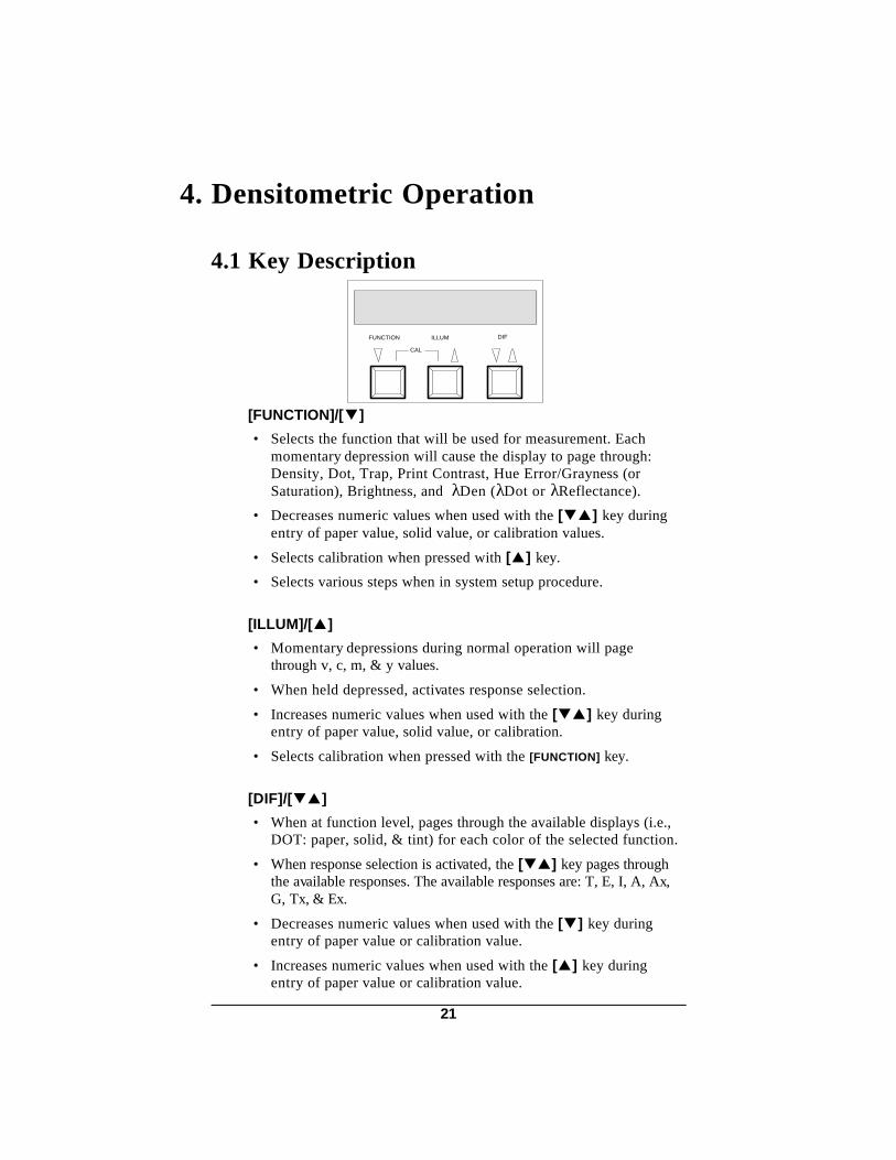
4.1 Key Description
[FUNCTION]/[▼]
• Selects the function that will be used for measurement. Eachmomentary depression will cause the display to page through:Density, Dot, Trap, Print Contrast, Hue Error/Grayness (orSaturation), Brightness, and λDen (λDot or λReflectance).
• Decreases numeric values when used with the [▼▲] key duringentry of paper value, solid value, or calibration values.
• Selects calibration when pressed with [▲] key.
• Selects various steps when in system setup procedure.
[ILLUM]/[▲]
• Momentary depressions during normal operation will pagethrough v, c, m, & y values.
• When held depressed, activates response selection.
• Increases numeric values when used with the [▼▲] key duringentry of paper value, solid value, or calibration.
• Selects calibration when pressed with the [FUNCTION] key.
[DIF]/[▼▲]
• When at function level, pages through the available displays (i.e.,DOT: paper, solid, & tint) for each color of the selected function.
• When response selection is activated, the [▼▲] key pages throughthe available responses. The available responses are: T, E, I, A, Ax,G, Tx, & Ex.
• Decreases numeric values when used with the [▼] key duringentry of paper value or calibration value.
• Increases numeric values when used with the [▲] key duringentry of paper value or calibration value.
FUNCTION ILLUM DIF
CAL
21

4.2 Function Selection
Each momentary depression of [FUNCTION] in densitometric modewill sequentially page through the available function: DEN (or DEN-P),DOT, TRAP, PC (or PC-P), H/G (or H/S) or H/G-P (or H/S-P),BRIGHT, and λDEN (or λDOT, or λREFL).
Functions can be turned on, off, or changed in DensitometricOperation Parameters, Section 8.3.
CAL
PRESS TO SELECTNEXT FUNCTION
OR
FUNCTION ILLUM DIF
c 0 . 5 0 9 Dm 0 . 2 3 4 y 0 . 1 4 7
#D E N
#H / G
H / S
C T O MH 2 4 . 6 G 2 9 . 2
B R I G H T B 8 2 . 3 1
D E N 0 . 4 4 6 D4 4 0 n m
OR
D O TOR
R E F L
c 0 . 5 0 9 Dm 0 . 2 3 4 y 0 . 1 4 7v 0 . 3 6 3
C O L O R P A P E Rv 0 . 0 6 6 P#D O T
C O L O R S O L I Dc 1 . 0 6 5 s#D O T
C O L O R T I N Tv#D O T 6 9 . 8 %
C O L O R P A P E Rv 0 . 0 6 6 P#T R A P
R E A D O V E R P R I N T8 3 T#T R A P Y
C
C O L O R S O L I Dv 0 . 0 6 6 s#P C
C O L O R T I N Tv#P C 5 5 . 6 PC
> "# " is the selected response (A, E, I, or T).
22

4.3 Response Selection
The 938 allows you to automatically select between differentresponses when desired. The available responses are:
• T - represents ANSI Status T. • E - represents a European response which uses a 47B filter for
yellow. • I - represents a narrow band response. • A - represents ANSI Status A, which is used in photo finishing
applications. • G - represents the normal X-Rite graphic arts wideband response.
It is similar to Status T response but has more sensitivity to denseryellow inks.
• Ax, Tx, Ex - closely match the X-Rite 400 series responses.
Applications:- For DIN wide band, Response "E" would be selected.- For DIN narrow band and SPI type, Response "I" would be selected.
To select a response:
1) At normal operation, hold downthe [▲] key until "SELECT DENRESPONSE" is displayed.
FUNCTION ILLUM DIF
CAL
SELECTDEN RESPONSE
c 0 . 5 0 9 Dm 0 . 2 3 4 y 0 . 1 4 7
D E N T
Hold
23

2) The active response is displayed.Press [▼▲] to select a differentresponse.
3) Press [▼] to exit after selectionis made.
FUNCTION ILLUM DIF
CAL
R E S P O N S E Te x i t T O G G L E
Press
FUNCTION ILLUM DIF
CAL
R E S P O N S E Te x i t T O G G L E
R E S P O N S E AR E S P O N S E IR E S P O N S E E
Press
R E S P O N S E AxR E S P O N S E GR E S P O N S E TxR E S P O N S E Ex
24

4.4 Density Operation
The 938 can measure density with or without paper subtracted fromthe measurement (as selected in modes, refer to Section 8.3 forselection).
To take a density measurement:
1) Select desired response (ifrequired, Sec. 4.3).
2) Press [FUNCTION] to select DEN.
3) Center target window over thepatch to be measured. > If density minus paper option is
activated, paper must bemeasured first. Or, paper valuescan be manually entered by,holding down the [▼▲ ] key,pressing [▼ ] to decrease value or[▲ ] to increase value.
4) Lower unit to target windowand firmly hold compressed."READING DEN T" (i.e., theselected response) willmomentarily be displayed, andthen the data. > If density values display during
paper measurement, press the[▼▲ ] key (while unit is still down)to enter measurement as paper.
Release unit after data isdisplayed.
5) The unit will display the density(with or without paper) values.
> To redisplay the function andresponse, press [▼▲ ] key.
FUNCTION ILLUM DIFCAL
c 0 . 5 0 1 Dy 0 . 1 4 7
T
Press
m 0 . 2 3 4D E N
v 0 . 055m 0 . 234
c 0 . 052Dy 0 . 092
R E A D I N G D E N T
c 0 . 0 5 2 Dm 0 . 2 3 4 y 0 . 0 9 2v 0 . 0 5 5
Visual value
Magenta value
Cyan value
Yellow value
Density (D willdisplay if -paper).
25

4.5 Dot Operation
The instrument will display last solid density and dot measurementfor each color (v, c, m, & y).
In auto color mode, the 938 will automatically display and update theselected solid or dot measurement. In manual color mode, the displaywill remain at the selected color until changed. See Section 8.3 for autoor manual color mode selection.
Dot is calculated using the Murray-Davies or Yule-Nielson formula.
The Murray-Davies formula for calculating dot is:
Dt = Density of the tint -paper. Ds = Density of the solid -paper.
The Yule-Nielson formula allows you to compensate for the amountof reflected light (absorbed & trapped) lost when taking a dotmeasurement. This can be accomplished by changing the "n" factor.Listed below are approximate "n" factors for some commercially usedmaterials.
Material "n" Factor Material "n" Factor Uncoated Paper 2.7 3M Color Key 4.0 Coated Paper 1.6 - 1.7 Agfa Gevaert Gevaproff 1.43M Transfer Key 1.9 Newsprint 2.5DuPont Cromalin 2.6
The Yule-Nielson formula for calculating dot is :
The 938 defaults to Murray-Davies formula (n= 1.000). If you wouldlike to change to a Yule-Neilson value, refer to Section 8.3.
To take a dot measurement:
1) Select desired response (ifrequired, Sec. 4.3).
2) Press [FUNCTION] to select DOT.
% DOT= x1001 - 10 -Dt
1 - 10 -Ds
% DOT= x1001 - 10 -Dt/n
1 - 10 -Ds/n
FUNCTION ILLUM DIF
CAL
Press
v 0 . 0 5 0 PC O L O R P A P E R
TD O T
26

3) Place target window on paperand lower unit to target window. Hold firmly compressed untildata is displayed. > Paper value can also be manually
entered by, holding down the[▼▲] key, pressing [▼] to decreasevalue or [▲] to increase value.
> If solid value is displayed duringpaper measurement, press the[▼▲ ] key twice (while unit is stilldown) to enter measurement aspaper.
4) Center target window oversolid patch to be measured,lower unit to target window. Hold compressed until datais displayed. > When the Store Data function (Sec.
6) is used in conjunction with Dotoperation, only one solid value canbe stored at a time. The last solidmeasured will be the stored value.
5) Center target window over tintthat corresponds to theprevious solid measurement,and lower unit to targetwindow.
6) Detection of solids and tints isautomatic. After a measurement(while the 938 is still helddown), momentarily pressingthe [▼▲] key will allow you tooverride the auto mode andselect paper, solid, or tint.When the 938 is released theselected option will be updated.
R E A D I N G D O T T
m 0 . 0 5 2 PP A P E R
D O T T
R E A D I N G D O T T
c 1 . 0 7 9 sD O T TS O L I D
R E A D I N G D O T T
c 7 0 . 4 %D O T TT I N T
27

7) Momentarily pressing the[▼▲] key display will showthe tint, solid, and paper valueof the selected color.
8) Momentarily pressing the [▲]key, the display will show thelast value for each color of theselected mode (tint, solid, &paper). > Some values may display zero if
all solid (v, c, m, & y) andcorresponding dot values were notmeasured.
FUNCTION ILLUM DIF
CAL
D O T TC O L O R
Press
T I N T
D O T TC O L O R S O L I D
D O T TC O L O R P A P E R
c 0 . 0 4 0 P
c 1 . 0 7 9 s
c 7 0 . 4 %
Cyan Dot Value
Cyan Solid Value Minus Paper
Cyan Paper Value
FUNCTION ILLUM DIF
CAL
D O T TC O L O R
Press
T I N T
D O T TC O L O R T I N T
D O T TC O L O R T I N T
m 3 4 . 5 %
y 2 7 . 3 %
v 4 3 . 7 %
D O T TC O L O R T I N T
c 7 0 . 4 %
Visual Dot Value
Yellow Dot Value
Magenta Dot Value
Cyan Dot Value
28

4.6 Trap Operation
Trap is electronically calculated after a measurement of the overprint,2nd ink printed, and 1st ink printed. The 938 contains three methods forcalculating trap:
1) Preucil (GATF) formula
2) Brunner formula
3) Newsprint formula
Dop = Den of overprint -paperD2 = Den of 2nd ink -paper D1 = Den of 1st ink -paperDtm = Theoretical max printing Den -paper
To select Brunner or the Newsprint formula, refer to Section 8.3.Preucil is the factory default setting.
To take a trap measurement:
1) Select desired response (ifrequired, Sec. 4.3).
2) Press [FUNCTION] to selectTRAP.
3) Place target window on paperand lower unit to target window.Hold firmly compressed untildata is displayed. > Paper value can also be manually
edited by, holding down the [▼▲ ]key, pressing [▼ ] to decreasevalue or [▲ ] to increase value.
> If overprint value is displayedduring paper measurement, pressthe [▼▲ ] key (while unit is stilldown) to enter measurement aspaper.
Dop - D1
D2% TP = x100
-Dop% TB = x1001 - 10
1 - 10-(D1 + D2)
Dop - D1
% T = x100Dtm - Dop1 +( )log
D2Dtm - D21 +( )log
N
FUNCTION ILLUM DIFCAL
c 0 . 5 0 1 PT
Press
C O L O RT R A P
P A P E R
R E A D I N G T R A P T
m 0 . 0 5 2 PP A P E R
T R A P T
29
Trap Operation...continued
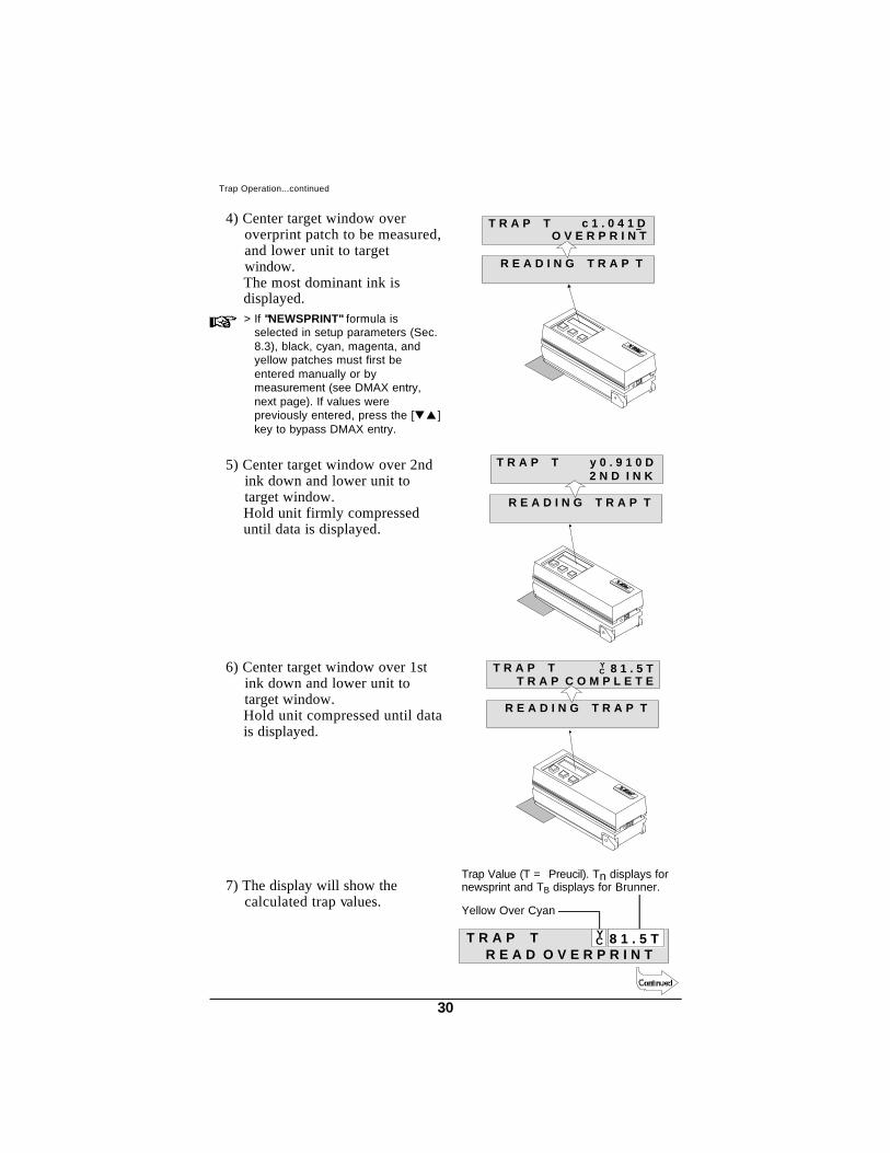
4) Center target window overoverprint patch to be measured,and lower unit to targetwindow. The most dominant ink isdisplayed. > If "NEWSPRINT" formula is
selected in setup parameters (Sec.8.3), black, cyan, magenta, andyellow patches must first beentered manually or bymeasurement (see DMAX entry,next page). If values werepreviously entered, press the [▼▲ ]key to bypass DMAX entry.
5) Center target window over 2ndink down and lower unit totarget window. Hold unit firmly compresseduntil data is displayed.
6) Center target window over 1stink down and lower unit totarget window. Hold unit compressed until datais displayed.
7) The display will show thecalculated trap values.
R E A D I N G T R A P T
c 1 . 0 4 1 DO V E R P R I N T
T R A P T
R E A D I N G T R A P T
8 1 . 5 TT R A P C O M P L E T E
T R A P T YC
R E A D I N G T R A P T
y 0 . 9 1 0 D2 N D I N K
T R A P T
R E A D O V E R P R I N TT R A P T Y
C 8 1 . 5 T
Trap Value (T = Preucil). Tn displays fornewsprint and TB displays for Brunner.
Yellow Over Cyan
30

9) By momentarily pressing the[▼▲] key the display willtoggle between the trap valueand selected paper value.> Momentarily pressing the [▲ ] key
at paper level will display thedifferent paper value for vcmy.
DMAX ENTRY (TRAP Newsprint Only)
DMAX can be entered by a measurement or by using key entry.
• If the measurement method is used, the resulting DMAX valuesfor v, c, m, & y filter responses are the sum of that filter responsedensity on the 4 colors.
• If the key entry method is used, press the [▲] key to select thecolor and adjust the value by, holding the [▼▲] key, andpressing the [▼] to decrease value or the [▲] to increase value.When all 4 DMAX values are correct, press the [▼▲] key andfollow direction from Step 4 on previous page.
FUNCTION ILLUM DIF
CAL
c 0 . 0 4 1 PTT R A P
Press
TR E A D O V E R P R I N T
P A P E RC O L O R
T R A P 8 1 . 5 Tyc
31

4.7 Print Contrast
The print contrast function provides the ability to monitor a 3/4 tonearea and is useful when determining the optimum printing density. Printcontrast can be measured with or without paper subtracted from themeasurement. In auto color mode, the 938 will automatically display andupdate the selected solid or dot measurement. In manual color mode,the display will remain at the selected color until changed. Refer toSection 8.3 for density -paper and color mode selection.
The calculation for PC is:
Ds = Solid density -paper* Dt = Tint density -paper* * Or absolute as set by modes
To take a print contrast measurement:
1) Select desired response (ifrequired, Sec. 4.3).
2) Press [FUNCTION] to select PC.
3) Center target window over solidpatch to be measured, and lowerunit to target window. Hold firmly compressed untildata is displayed.> If PC minus paper option is selected,
paper must be measured first. Thepaper value can also be manuallyentered by, holding down the[▼▲ ] key, pressing [▼ ] todecrease value or [▲ ] to increasevalue.
> When the Store Data function(Sec. 6) is used in conjunction withDot operation, only one solid valuecan be stored at a time. The lastsolid measured will be the storedvalue.
DS - Dt%PC = x100DS
FUNCTION ILLUM DIFCAL
y 0 . 9 8 3 sS O L I D
T
Press
C O L O RP C
R E A D I N G P C T
c 1 . 1 1 7 sP C TS O L I D
32

4) Center target window over 75%tint that corresponds to theprevious solid measurementand lower unit to targetwindow. Hold compressed until data isdisplayed.
5) By momentarily pressing the[▼▲] key, the display willshow the PC solid and paper(if selected) values of theselected color. > Paper values will display if P/C
-paper was selected in modes.
6) By momentarily pressing the[▲] key, the display will showthe last color of the selectedmode (PC solid and paper).
7) Detection of solids and tints isautomatic. After a measurement(while the 938 is still helddown), momentarily pressingthe [▼▲] key will allow youto override the auto mode andselect paper, solid, or tint.When the 938 is released theselected option will be updated.
FUNCTION ILLUM DIF
CAL
TP C
Press
TC O L O R
T I N TC O L O R
P CS O L I D
c 1 . 1 1 8 s
c 3 3 . 7 PC
R E A D I N G P C T
c 3 3 . 7P C TT I N T
PC
FUNCTION ILLUM DIF
CAL
P C TC O L O R
Press
T I N T
P C TC O L O R T I N T
P C TC O L O R T I N T
m 3 4 . 8
y 4 1 . 5
v 5 1 . 7
P C TC O L O R T I N T
c 3 3 . 7
PC
PC
PC
PC
Cyan P/C Value
Cyan Solid Value. S displays if -paper.
Visual PC Value
Yellow PC Value
Magenta PC Value
Cyan PC Value
33

4.8 Hue Error/Grayness (Saturation) Operation
The 938 can measure hue error/grayness (or saturation), with orwithout paper subtracted from the measurement. Refer to Sec. 8.3 forselection procedure.
Hue Error, Grayness, and Saturation are calculated as follows:
DH = Highest density of Dr, Dg, or Db - Dp*DM = 2nd highest density of Dr, Dg, or Db - Dp* DL = Lowest density of Dr, Dg, or Db - Dp** Or absolute as set by modes.
The 938 defaults to Hue Error/Grayness. Hue Error/Saturation canbe set in place of Hue Error/Grayness (see Sec. 8.3).
To take a hue error/grayness (or saturation) measurement:
1) Select desired response (ifrequired, Sec. 4.3).
2) Press [FUNCTION] to select H/G(or S).
3) Center target window over thepatch to be measured.> If H/G (or S) -paper option is
selected, paper must be measuredfirst. The paper value can also bemanually entered by, holdingdown the [▼▲ ] key, pressing [▼ ]to decrease value or [▲ ] toincrease value.
DM - DL%H = x100DH - DL
%G = x100DH
DL DH - DLS =
FUNCTION ILLUM DIFCAL
C T O MG 8 . 5
T
Press
H 2 2 . 5H / G
34

4) Lower unit to target windowand hold compressed. "Reading H/G T" (i.e., theselected response) willmomentarily be displayed andthen the data. > If H/G values display during paper
measurement, press the [▼▲ ]key (while unit is still down) toenter measurement as paper.
5) The display will show the HueError/Grayness (orSaturation) values.> If minus paper was selected,
momentarily pressing the [▲ ] keyat paper level will display thedifferent paper values for vcmy.
H / G TH 4 2 . 8
Y T O MG 1 7 . 4
R E A D I N G H / G T
C T O MH 2 2 . 5 G 8 . 5H / G T
H / S TH 4 2 . 8
Y T O MS 0 . 8 0 6
Yellow Towards Magenta
Hue Error Value.H would display if-paper
Grayness Value.G would display if-paper
Saturation Value.S would display if-paper
OR
35

4.9 Brightness Operation
The 938 has the ability to measure the brightness of paper. Thespectral weight table is derived from 1987 TAPPI Spec - T 452 OM-87.
To take a brightness measurement:
1) Press [FUNCTION] to selectBRIGHT.
2) Center target window over thepaper to be measured.
3) Lower unit to target windowand hold compressed.
"READING BRIGHT" willmomentarily display.
Release unit after data isdisplayed.
4) The display will show thepaper brightness value.
FUNCTION ILLUM DIFCAL
B 8 0 . 2 4
Press
B R I G H T
B R I G H T B 8 2 . 5 9
R E A D I N G B R I G H T
B 8 2 . 5 9B R I G H T
Brightness Value
36

4.10 Spectral Operation
The 938 has a special feature that allows spectral data to be displayed as adensity, dot, or reflectance measurement. Values for the spectralmeasurements are in 20nm increments from 400 to 700 nanometers. Only oneof the three spectral measurement features can be used at a time. To selectbetween density, dot, and reflectance, refer to Section 8.3.
Only one wavelength value is displayed at a time. The 938 willautomatically display the wavelength with the maximum absorption(least reflectance). This procedure can be overridden allowing theselection of the wavelength you wish to display, by turning off AutoColor in Modes (see Sec. 8.3).
4.10.1 Spectral Density Operation A spectral density measurement can be taken with or without paper
subtracted from the measurement.
To take a spectral density measurement: > λDEN must be selected for spectral operation (see Sec. 8.3).
1) Press [FUNCTION] to selectλDEN.
2) Center target window overpatch to be measured, andlower unit to target window. Hold compressed until data isdisplayed.> If spectral density minus paper
option is selected, paper must bemeasured first. The paper valuecan also be manually entered by,holding down the [▼▲ ] key,pressing [▼ ] to decrease value or[▲ ] to increase value.
3) The display will show thewavelength with the maximumdensity value. > Pressing the [▲ ] will allow you to
page through the other densityvalues for each 20nm increment.
FUNCTION ILLUM DIFCAL
1 . 1 5 6 D
Press
6 2 0 n mD E N
D E N5 4 0 n m
1 . 0 8 7 D
R E A D I N G
1 . 0 8 7 D5 4 0 n m
D E N
D E N
Spectral Density Value
Wavelength "D" is displayed ifλDEN-P is enabled
37
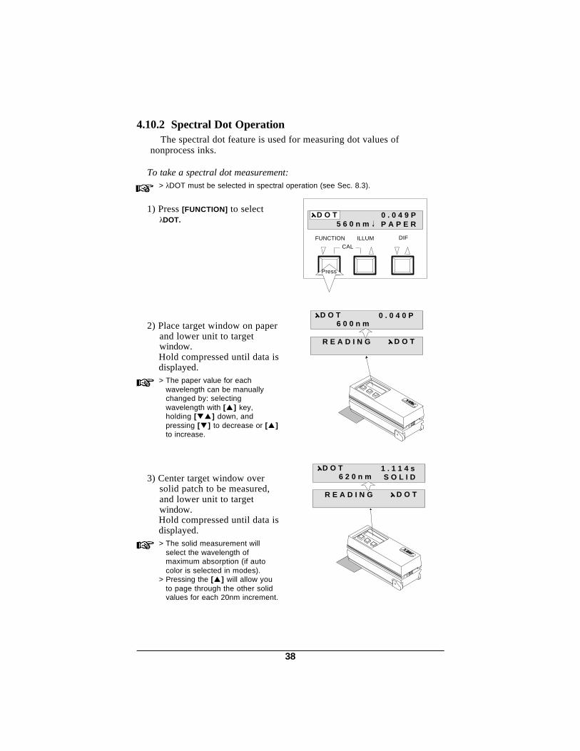
4.10.2 Spectral Dot Operation The spectral dot feature is used for measuring dot values of
nonprocess inks.
To take a spectral dot measurement: > λDOT must be selected in spectral operation (see Sec. 8.3).
1) Press [FUNCTION] to selectλDOT.
2) Place target window on paperand lower unit to targetwindow. Hold compressed until data isdisplayed.> The paper value for each
wavelength can be manuallychanged by: selectingwavelength with [▲ ] key,holding [▼▲ ] down, andpressing [▼ ] to decrease or [▲ ]to increase.
3) Center target window oversolid patch to be measured,and lower unit to targetwindow. Hold compressed until data isdisplayed.> The solid measurement will
select the wavelength ofmaximum absorption (if autocolor is selected in modes).
> Pressing the [▲ ] will allow youto page through the other solidvalues for each 20nm increment.
FUNCTION ILLUM DIFCAL
0 . 0 4 9 P
Press
5 6 0 n mD O T
P A P E R
R E A D I N G
0 . 0 4 0 P6 0 0 n m
D O T
D O T
R E A D I N G
1 . 1 1 4 s6 2 0 n m
D O T
D O T
S O L I D
38

4) Center target window over tintthat corresponds to theprevious solid measurement,and lower unit to targetwindow. Hold compressed until data isdisplayed.
5) The display will show the tintvalue at the wavelengthselected for the correspondingsolid.> Pressing the [▲ ] will allow you to
page through the other tint valuesfor each 20nm increment.
D O TT I N T6 2 0 n m
7 0 . 8 %
R E A D I N G
7 0 . 8 %6 2 0 n m
D O T
D O T
T I N T
Spectral Tint Value
Wavelength
39

4.10.3 Spectral Reflectance Operation The 938 allows you to measure a sample and display it’s relative
reflectance.
To take a spectral reflectance measurement: > λREFL must be selected in spectral operation (see Sec. 8.3).
1) Press [FUNCTION] to selectλREFL.
2) Center target window oversample to be measured andlower unit to target window. Hold compressed until data isdisplayed.
3) The display will show thewavelength with the maximumabsorption (minimumreflectance).> The other reflectance values can
be displayed by pressing the [▲ ]key.
FUNCTION ILLUM DIFCAL
7 . 0 2
Press
6 2 0 n mR E F L
R E F L4 4 0 n m
4 . 9 7
R E A D I N G
4 . 9 74 4 0 n m
R E F L
R E F L
Relative Reflectance
Wavelength
40

5. Measurement Averaging Procedure
When averaging is activated in setup, averaging operation will occur onall the functions that are turned on in modes. Refer to Section 8.1 toactivate averaging procedure.
There are two averaging methods that are used:
• SAMPLES AVERAGED - allows you to enter the number ofmeasurements you will make (1-99) at various locations on a sample, toobtain an average value.
• SUB AVERAGE - allows you to enter the number of measurementsthe unit will take (1-6) on a sample at a single location, to obtain anaverage value.
> When average and sub average are set to one, no averaging is performed andno averaging messages will be displayed.
The following example was taken in the absolute measurement modeusing: XYZ function, two sub averages, and two measurement averages.
1) Press [FUNCTION] to selectXYZ measurement space.
2) Center the target window overfirst area on the sample to bemeasured. Lower unit to targetwindow and hold compressed."READING XYZ C2 1 OF 2", "2 OF2", and the data is display.
After releasing the read head,"MEASURE SAMPLE 2 OF 2" isdisplayed.
FUNCTION ILLUM DIF
CAL
Press
X 4 . 1 2Y 2 . 8 7 Z 2 . 4 1
C2X Y Z
2 OF 2MEASURE SAMPLE
READING XYZ 2C
READING XYZ 2C
2 OF 2
1 OF 2
XYZ C 2 X 63.90Y 65.03 Z 23.02
41

3) Center the target window oversecond area on the sample tomeasure. Lower unit to targetwindow and hold compressed."READING XYZ C2 1 OF 2" and "2OF 2" will momentarily bedisplayed, and then theaveraged data.
4) The display will show theaverage absolute values forXYZ.
> Do not jar or lift reading headduring sub averagingmeasurements.
> When averaging is activated, thisbasic procedure must be followedfor all measurements.
CALCULATEDAVERAGE
READING XYZ 2C1 OF 2
READING XYZ 2C2 OF 2
X 63.91Y 65.04 Z 23.02
X Y Z C2
X Y Z X 63.91Y 65.04 Z 23.02
FUNCTION ILLUMINANT X VALUE
Y VALUE Z VALUE
C2
42

6. Store Data Operation
The data storage feature allows the unit to store measurement datafor up to 500 readings. (Refer to Sec. 8.5 to activate.)
> The store data feature can not be used when measuring Trap.
There are four basic operations that can be utilized in the store datafunction.
• Group Selection - group tagging allows you to assign groupnumbers to the stored values. Group tagging is only accessablethrough RCI with a software package such as SpectroStart.
• Send data - allows all of the stored data to be transferred to acomputer or serial printer. Data is sent as determined by thefunction displayed and modes enabled.
• Delete last - allows only the last measurement data to be deletedfrom stored memory.
• Clear all - causes all of the measured data in stored memory tobe deleted.
The following sample (made in XYZ absolute) illustrates thedifferent functions of the data storage feature.
1) Press [FUNCTION] to select XYZmeasurement space.
2) Measure first sample.
"READING XYZ C2" ismomentarily displayed, then themeasurement.
Upon release of the read head,"DATA STORED 1 OF 500" andthen the measurement isdisplayed.
FUNCTION ILLUM DIF
CAL
Press
X 4 . 1 2Y 2 . 8 7 Z 2 . 4 1
C2X Y Z
XYZ C 2 X 3.41Y 3.47 Z 4.25
DATA STORED1 OF 500
READING XYZ 2C
XYZ C 2 X 3.41Y 3.47 Z 4.25
43

3) Measure second sample.
"READING XYZ C2" ismomentarily displayed, then themeasurement.
Upon release of the read head,"DATA STORED 2 OF 500" andthen the measurement isdisplayed.
SEND DATA
4) Press both [ILLUM] and [DIF] atthe same time.
5) Press [DIF] to transfer data (goto Step 7).
If "NO" is selected, press[FUNCTION] and advance to Step 6.
Sample Printout
FUNCTION ILLUM DIFCAL
PRESS AT SAME TIME
XYZ C 2 X 3.45Y 3.52 Z 4.29
SEND DATA ?NO 2 YES
TRANSMITTING1 OF 2
TRANSMITTING2 OF 2
DATA TRANSFERCOMPLETE
Press
XYZ C 2 X 3.45Y 3.52 Z 4.29
DATA STORED2 OF 500
READING XYZ 2C
XYZ C 2 X 3.45Y 3.52 Z 4.29
44

DELETE LAST MEASUREMENT
6) Press [DIF] to delete the lastmeasurement made (this stepcan be repeated to deleteseveral of the lastmeasurements).
If "NO" is selected, press[FUNCTION] and advance to Step 7.
CLEAR ALL DATA
7) Press [DIF] to clear all storedmeasurement data taken.
If "NO" is selected, press[FUNCTION] to return to normaloperation.
> The Send/Clear data function maybe exited at anytime by pressing[FUNCTION] and [ILLUM] at thesame time.
> Refer to Section 8.5 to activate thestore data function.
> "STORAGE FULL" will display onall measurements after 500 storedmeasurements has been reached.
NO 2 YES
LAST DELETED
DELETE LAST ?
Press
NO 1 YES
DELETE LAST ?
Number of MeasurementsStored
NO 2 YES
DATA CLEARED
Press
CLEAR ALL ?
XYZ C X 3.45Y 3.52 Z 4.29
2
45

7. CalibrationThe 938 should be calibrated to the X-Rite standard the first thing each
day and every four hours of operation thereafter. However, a "NEEDCALIBRATION" message will appear in the display if
•The calibration procedure has not been performed for 24 hours.•There is a 10°C change in temperature since the last calibration.•Zero reflectance is measured improperly.•The lamp output changes.
Whenever this message appears the calibration procedure should beperformed before another measurement is taken to ensure accuracy.
Important Calibration Notes
• If you change apertures you must change the aperture setting,read zero reflectance, & calibrate the unit (see Section 7.2, steps1, 2, & 5a thru 5d).
• Dirt or dust in the optics area will cause an inaccurate calibrationreading. Refer to Section 12.2 for the optics cleaning procedure.
• The ceramic Reflection Standard is dramatically affected bysmudge marks, dust, and finger prints. The standard should becleaned using a mild soap and warm water solution, thoroughlyrinsed with warm water, and wiped dry with a lint free cloth. Youmust let the standard dry completely before taking a calibrationreading.
• If you are having linearity problems it’s possible that there is dustin the optics or Zero Reflectance has drifted. If you improperlymeasure Zero Reflectance the unit can not automatically detectthe drift. If you suspect this is the case, you should manuallyactivate Read Zero Reflectance by performing Steps 1, 2, & 5 ofSection 7.2.
• Do not move the 938 while taking a calibration measurement. Ifmotion is detected an error message will be displayed andcalibration aborted.
46

7.1 Positioning the 938 Onto the Standard
You must set the 938 on the white standard so that the maximumamount of the bottom rubber pad of the shoe resides on the standard, andthe target is centered on the circle. If you do not, the unit may rockslightly and cause an erroneous reading of the standard.
1) Center the target window on the White circle, making sure that therubber pad on the instrument is completely on the standard and is flat.
2) Take the measurement.
BOTTOM VIEW
47

Shown below is an IMPROPER METHOD of measuring the standard.
BOTTOM VIEW
INCORRECT!
48

Reflection StandardP/N 968-62Serial No. CXXXXXXXP-XXXXX
IMPORTANT!
by smudge marks and dust; and mustbe kept clean.
The standard is dramatically affected
Date XX/XX/XXREFL[%]
WAVE[nm]
390400410420430440450460480500520540560580600620640660680700710
X-Rite
62.1076.7081.8885.0285.9986.1286.4886.7487.0587.4287.3687.0886.7286.2585.7185.1884.5284.0283.3582.6981.99
CALIBRATIONCHECK
C/2 (WHITE)
L*a*b*
Instrument Model No.
Instrument Serial No.
COLOR CHECKRefer to section in operation manualappendix for procedure to obtainreference values.
DATE: TEMP:ILLUM/OBS: APERT:
REFERENCES VALUESSTEP
1 (White)2 (Blue)3 (Brown)
L* a* b*
Notes:
X-Rite Reflection Standard
The Calibration Values for the white spot are affected by theenvironment and cleaning method of the standard.
If the white spot does not measure correctly, it could be that theunit needs to be calibrated; there is dust in the optics; or thestandard has smudge marks or is dirty.
The ceramic standard should be cleaned using a mild soap andwarm water solution, thoroughly rinsed with warm water, andwiped dry with a clean, lint free cloth.
If you lose your envelope, you can obtain the calibration valuesfrom the back page of this manual, or, by looking at them in thecalibration procedure. Otherwise, you can contact X-Rite with theserial number of your standard and get the values.
49

7.2 Calibrating to the White Standard> If you are changing aperture size: Do steps 1, 2, & 5a thru 5d. Skip steps 3 & 4.
1) Press both [FUNCTION] and[ILLUM] at the same time.
2) Select "YES", press [DIF].
The copyright and softwareversion are momentarilydisplayed.
3) "READ CAL WHITE" is displayed.At this point you have twooptions:
• You can measure the whitespot on the standard (go tostep 4). This is standardoperating procedure.
• Or, you can press[CHANGE] to change thecalibration values for the 21different spectral values orto change the aperturesetting. This procedure isonly used when you want tocalibrate to a differentstandard or you changeapertures. Go to step 6.
FUNCTION ILLUM DIFCAL
PRESS AT SAME TIME
X 4 . 1 2Y 2 . 8 7 Z 2 . 4 1
C2X Y Z
FUNCTION ILLUM DIF
CAL
CALIBRATE ?NO YES
Press
X-Rite Ver XXXXCopyright 1990
FUNCTION ILLUM DIF
CAL
READ CAL WHITE
READ CAL WHITEEXIT CHANGE
5SEC
50

4) Measure the WHITE patch onthe standard. You must holdthe unit depressed until all fivereadings have been completed.
> You must set the unit on thestandard so that the maximumamount of the bottom rubber padof the shoe resides on the standard(refer to Section 7.1).
"CAL READING 1 OF 5" thru "CALREADING 5 OF 5" is displayed;then "CALIBRATION UPDATED."The procedure is finalized andthe unit returns back to mainmenu.> During the Cal Reading, the read
head must remain down and stableor an error message may occur.
> If "PLEASE WAIT XX (1-30)SECONDS" is displayed duringcalibration, continue to hold readhead down until calibrationreadings are over. This will onlyoccur if the calibration procedure isperformed within 30 seconds of aprevious measurement.
> If "READ ZERO REFLECTANCE" is displayed after reading thewhite spot, go to step 5. This willonly occur if the calibration valuesfor zero reflectance have drifted.
THE FOLLOWING STEPS (5 & 6) ARE ONLY NECESSARY IF YOU WANT TOMEASURE ZERO REFLECTANCE, CHANGE SPECTRAL VALUES, or CHANGEAPERTURE SIZE.
5) Steps 5a - 5d are only necessary if "READ ZERO REFLECTANCE" isdisplayed, you want to manually activate Zero ReflectanceMeasurement, or YOU WANT TO CHANGE APERTURE SIZE.
Zero Reflectance is defined as, "measuring air with no ambient light."
This can be accomplished by holding the shoe compressed (take areading) in a dark room. In some cases, it is possible to just take areading under a desk with no direct light.
To manually activate zero reflectance measurement or if youwant to change aperture size, see next page.
CALIBRATIONUPDATED
CAL READING 1 OF 5
CAL READING 2 OF 5
CAL READING 3 OF 5
CAL READING 4 OF 5
CAL READING 5 OF 5
WHITE
51

5a) Select "CHANGE", press [DIF].
5b) Select "NO", press [FUNCTION].
5c) Press [FUNCTION] to select"NEXT" if the aperture size iscorrect (go to step 5d).
If the aperture size is wrongpress [DIF] to change size.> If you change aperture size you
will be sent back to step 5a afterpressing [NEXT]. At that pointyou must read Cal White, thenZero Reflectance.
5d) Measure Zero Reflectance.> You must measure Cal White after
Zero Reflectance, if you manuallyselected Zero reflectance
6a) Steps 6a - 6c are onlynecessary if you want to changethe 21 spectral calibrationvalues.
Press [YES]
FUNCTION ILLUM DIF
CAL
NEW CAL VALUES?NO YES
FUNCTION ILLUM DIF
CAL
READ CAL WHITEEXIT CHANGE
Press
FUNCTION ILLUM DIFCAL
NEW CAL VALUES?NO YES
Press
FUNCTION ILLUM DIF
CAL
APERTURE = 8.0mmNEXT TOGGLE
4.0mm8.0mm20 mm
READ ZERO REFL.EXIT
52

6b) Enter the value for 390nm.
> The [DIF] key advances the cursor tothe next value to be edited.
> Hold [DIF] depressed then press[▼] to decrease value or [▲] toincrease value.
6c) After entering value press[FUNCTION] to advance.
Enter the value for 400nm.Repeat procedure for all valuesAfter entering all 21 spectralvalues go back to step 4.
FUNCTION ILLUM DIF
CAL
DECREASE +
+
SET 390nm VALUE53.22NEXT
INCREASE
FUNCTION ILLUM DIF
CAL
DECREASE +
+
SET 400nm VALUE53.22NEXT
INCREASE
53

8. Setting System Parameters
8.1 Averaging
The averaging feature allows the unit to make several measurementsfrom the same and/or different locations on a sample. This will allow youto have a better overall average of a sample color. The averaging featurehas two functions:
• SAMPLES AVERAGED - allows you to enter the number ofmeasurements you will make (1-99) at various location on asample, to obtain an average value.
• SUB AVERAGE - allows you to enter the number of measurementthe unit will take (1-6) on a sample at a single location, to obtainan average value.
> When average and sub average are set to one, no averaging is performed andno averaging messages will be displayed.
1) Press both [FUNCTION] and[ILLUM] at the same time.
> To exit Averaging Setup: Press[FUNCTION] and [ILLUM] at thesame time and the unit will returnback to normal operation.
2) Select "NO", press [FUNCTION].
FUNCTION ILLUM DIFCAL
PRESS AT SAME TIME
X 4 . 1 2Y 2 . 8 7 Z 2 . 4 1
C2X Y Z
FUNCTION ILLUM DIF
CAL
CALIBRATE ?YES
Press
NO
54

3) Select "YES", press [DIF].
4) Select the amount (1-99) ofsample measurements required.
• Hold down [DIF] and press[▼] to decrease thesample measurementnumber or press [▲] toincrease the samplemeasure number.
• Press [FUNCTION] toadvance to the SubAverage number entry.
5) Select the amount (1 - 6) of subaverage measurements required.
• Press [DIF] to select subaverage number.
6) Press [NEXT] to return to "SETAVERAGING ?" Menu. Or, press[FUNCTION] and [ILLUM] at thesame time to exit to normaloperation.
FUNCTION ILLUM DIF
CAL
Press
SET AVERAGING ?YESNO
FUNCTION ILLUM DIF
CAL
SAMPLES AVERAGED 01
INCREASEDECREASE +
+
NEXT
FUNCTION ILLUM DIF
CAL
SUB AVERAGENEXT TOGGLE
1 through 6
1
55

8.2 Colorimetric Operation Parameters
Colorimetric operation setup allows you to select various options, andindividually turn On or Off certain functions. When a function is turnedoff it will not be displayed during operation.
1) Press both [FUNCTION] and[ILLUM] at the same time.
> T o e x i t C o l o r i m e t r i cO p e r a t i o n S e t u p : P r e s s[FUNCTION] and [ILLUM] at thesame time and the unit will returnback to normal operation.
2) Select "NO", press [FUNCTION]twice.
3) Select "YES", press [DIF].
The procedure for the following steps is to press [TOGGLE] to change an option, or toturn a particular function on or off. Press [NEXT] to advance to the next step.
FUNCTION ILLUM DIFCAL
PRESS AT SAME TIME
X 4 . 1 2Y 2 . 8 7 Z 2 . 4 1
C2X Y Z
FUNCTION ILLUM DIF
CAL
CALIBRATE ?YES
Press
NO
Twice
FUNCTION ILLUM DIF
CAL
COLOR OPERATION ?YES
Press
NO
56

4) Select SOFT TONE, LOUDTONE, or TONE OFF.
5) Select XYZ ON, X%Y%Z%(RBG) ON, or OFF.
6) Select Yxy ON or OFF.
7) Select Lab (CIE), Lab(Hunter), or OFF.
8) Select L*u*v* ON or OFF.
9) Select L*C*h° ab, CMC, uv,or OFF.
10) Select Whiteness ON orOFF.
11) Select Yellowness ON orOFF.
12) Select Auto Reference ONor OFF. When set to On, areference is automatically selectedduring a measurement. When setto Off, a reference must manuallybe selected before a measurement.
> Exit via [NEXT] OR press[FUNCTION] & [ILLUM] at the same time to return back to normal operation.
Press
TOGGLENEXT
(ab) ON
(uv) ONOFF
Press
Luv ONTOGGLENEXT
ONOFF
Lab (CIE) ON
Press
TOGGLENEXTLCh (ab) ON
Press
WHT ONTOGGLENEXT
ONOFF
BACK TO STEP 3
AUTO REF ONTOGGLE
Press
NEXT
ONOFF
Press
YEL ONTOGGLENEXT
ONOFF
(CIE) ON
OFF
(HUNTER)ON
Press
Yxy ONTOGGLENEXT
ONOFF
(CMC) ON
Press
SOFT TONETOGGLENEXT
SOFTLOUD
XYZ ONTOGGLE
Press
NEXT XYZ ONX%Y%Z%(RGB) ONXYZ OFF
OFF
57

8.3 Densitometric Operation Parameters
Densitometric operation setup allows you to change various options,and individually turn On or Off certain functions. When a function isturned off it will not be displayed during operation.
1) Press both [FUNCTION] and[ILLUM] at the same time.
> T o e x i t D e n s i t o m e t r i cO p e r a t i o n S e t u p : P r e s s[FUNCTION] and [ILLUM] at thesame time and the unit will returnback to normal operation.
2) Select "NO", press [FUNCTION]three times.
3) Select "YES", press [DIF].
The procedure for the following steps is to press [TOGGLE] to change an option, or toturn a particular function on or off. Press [NEXT] to advance to the next step.
4) Select AUTO COLOR ON or OFF.When set to Auto On, colors in Dot andPC will automatically be updated. Inspectral operation mode (see Sec. 4.10),max absorption point will displayautomatically. When set to Auto Off, thecolor selected in Dot and PC will remainthe same until changed. In Spectralmode, the wavelength will remain thesame until changed.
FUNCTION ILLUM DIFCAL
PRESS AT SAME TIME
X 4 . 1 2Y 2 . 8 7 Z 2 . 4 1
C2X Y Z
Press
AUTO COLOR ONTOGGLENEXT
ONOFF
FUNCTION ILLUM DIF
CAL
CALIBRATE ?YES
Press
NO
ThreeTimes
FUNCTION ILLUM DIF
CAL
DEN OPERATION ?YES
Press
NO
58

5) Select DEN (absolute),DEN-P, or OFF.
6) Select DOT ON or OFF.
7) Select new "n" factor (ifrequired). Change "n" factorby pressing and holding the[▼▲ ] key, and pressing the [▼ ]key to decrease value, orpressing the [▲ ] to increasevalue. When set to "1.000", theMurray-Davies formula is used.
8) Select Trap News, Preucil,Brunner, or OFF.
9) Select PC (absolute), PC-P,or OFF.
10) Select H/G (absolute),H/G-P, OFF, H/S (absolute),or H/S-P.
11) Select BRIGHTNESS ON orOFF.
12) Select λREFL ON, λDOT ON,λDEN ON, or OFF.
> Exit via [NEXT] OR press[FUNCTION] & [ILLUM] atthe same time to return backto normal operation.
Press
DEN ONTOGGLENEXT DEN ON
DEN-P ON
Press
DOT ONTOGGLENEXT
OFF
DEN OFF
ON
INCREASEDECREASE +
+
Yule/NielsonNEXT 1.000Yn
Press
TOGGLENEXT
ON
Press
H/G ONTOGGLENEXT H/G ON
H/G-P ON
PC ON
Press
TOGGLENEXTBRIGHTNESS ON
BACK TO STEP 3
PC ONPC-PPC OFF
Press
TRAP Preucil ONTOGGLENEXT News ON
Preucil ON
DEN ON
DEN OFFREFL ON
Press
TOGGLENEXTDEN ON
DEN-P ON
Brunner ONTRAP OFF
H/G OFFH/S ONH/S-P ON
OFF
DOT ON
59

8.4 RS232 I/O Parameters
Your instrument comes equipped with a serial port that allows data tobe transmitted/received to/from an external device. Listed below are theavailable I/O parameters.
• "RCI ON/OFF" (Remote Control Interface) - enables or disablesthe ability to externally control the 938 via the I/O port.
• "BAUD" - determines the input/output rate (characters persecond) of the I/O port. Available outputs are: 300, 600, 1200,2400, 4800, and 9600.
• "CR WITH LF/CR WITH NO LF" (Carriage Return with LineFeed/Carriage Return with no Line Feed) - varies the delimiter atthe end of each line of data. When set to CR WITH NO LINEFEED, just a Carriage Return is sent at the end of a line of data.When set to CR WITH LF, a Carriage Return and then a LineFeed are sent at the end of a line of data.
• "HANDSHAKE" is used for data transmission. Handshake may beset to HANDSHAKE OFF (ASCII = 13H), PIN 5 CTS (Clear toSend), PIN 5 BUSY, or XON/XOFF ENABLED (ASCII =11H). Handshake should normally be set to OFF when it is notbeing used.
1) Press both [FUNCTION] and[ILLUM] at the same time.
> T o e x i t I / O S e t u p : P r e s s[FUNCTION] and [ILLUM] at thesame time and the unit will returnback to normal operation.
2) Select "NO", press [FUNCTION]four times.
FUNCTION ILLUM DIFCAL
PRESS AT SAME TIME
X 4 . 1 2Y 2 . 8 7 Z 2 . 4 1
C2X Y Z
FUNCTION ILLUM DIF
CAL
CALIBRATE ?YESNO
PressFourTimes
60

3) Select "YES", press [DIF].
> The basic procedure for the following steps is to press [TOGGLE] to set theI/O parameter. Press [NEXT] to advance to the next step.
4) Select RCI ON or OFF.
5) Select the BAUD Rate.
6) Select CR WITH LF or WITHNO LF.
7) Select HANDSHAKE OFF, PIN5 CTS, PIN 5 BUSY, orXON/OFF ENABLED.
> Exit via [NEXT] OR press[FUNCTION] & [ILLUM] atthe same time to returnback to normal operation.
FUNCTION ILLUM DIF
CAL
SETUP I/O ?YES
Press
NO
ONOFF
CR w/LFCR w/NO LF
HANDSHAKE
BACK TO STEP 3
300600
1200240048009600
Press
RCI ONNEXT
Press
BAUD 1200NEXT
Press
NEXTCR WITH LF
Press
NEXTHANDSHAKE OFF
TOGGLE
TOGGLE
TOGGLE
TOGGLEPIN 5 CTSPIN 5 BUSYXON/XOFF
OFF
ENABLED
61

8.5 Format Output Parameters
This procedure allows you set the output format of the RS232 port. Referto Section 10 for sample print outs. Listed below are the available options.
• AUTO PRINTOUT/STORE DATA/PRINTOUT OFF -determines if data will be transmitted after each measurement,stored until transmitted, or not allow data transfer.
AUTO PRINTOUT - enables the unit to transmit data after each measurement.STORE DATA - allows the unit to store up to 500 measurements.PRINTOUT OFF - disables the ability to output data via the RS232 portfrom a reading.
• COMPUTER/PRINTER/SPECTRAL - selects the output format ofthe data being transmitted.
COMPUTER FORMAT (used for wide printers) - transmits a group of datavalues per line of print (see Section 10, Print Example 2). PRINTER FORMAT (used for narrow printers) - transmits a group of datavalues in a single column format (see Section 10, Print Example 1).SPECTRAL FORMAT - transmits the measurement values for eachwavelength (400nm - 700nm) in 10 nanometer increments (see Section 10,Print Examples 4 & 5).
• λDEN PRINT ALL/MAX - determines printout format forspectral density, dot, and reflectance functions.
ALL - the values for each segment will printout in spectral function.MAX - only the max absorption point for spectral function will printout.
• ALL PRINT OFF/ON - determines which functions (XYZ, Yxy,etc.) are transmitted. When set to OFF, only the active functionwill be transmitted. When set to ON, all the functions that areturned on in the "Colorimeter & Densitometric OperationParameters" are transmitted.
• PRINT HEADER OFF/ON - enables or disables the header(XYZ, Yxy, etc.) during transmit.
• PRINT REF OFF/ON (Reference) - disables or enables theReference values during transmit.
• DEC. POINT ON/OFF (Decimal Point) - enables or disables thedecimal point during transmit.
1) Press both [FUNCTION] and [ILLUM] at the same time.
> T o e x i t F o r m a t S e t u p :Pres s [ F U N C T I O N ] and[ILLUM] at the same time and theunit will return back to normaloperation
FUNCTION ILLUM DIFCAL
PRESS AT SAME TIME
X 4 . 1 2Y 2 . 8 7 Z 2 . 4 1
C2X Y Z
62

2) Select "NO", press [FUNCTION] fivetimes.
3) Select "YES", press [DIF].
> The basic procedure for the following steps is to press [TOGGLE] to set theformat. Press [NEXT] to advance to the next step.
4) Select AUTO PRINTOUT,STORE DATA or PRINTOUT.
5) Select COMPUTER,PRINTER, or SPECTRAL.
6) Select λDEN PRINT ALL orMAX.
7) Select ALL PRINT OFF or ON.
FUNCTION ILLUM DIF
CAL
Press
NO YESFORMAT OUTPUT ?
PRINTERCOMPUTER
NEXT
NEXT
NEXT
TOGGLE
TOGGLE
TOGGLE
AUTO PRINTOUT
COMPUTER OUTPUT
DEN PRINT ALL
ALLMAX
PRINTOUTAUTO
Press
Press
Press
NEXT TOGGLEALL PRINT OFF
ONOFFPress
STORE DATAPRINTOUTOFF
SPECTRAL
FUNCTION ILLUM DIF
CAL
CALIBRATE ?YESNO
PressFiveTimes
63

8) Select PRINT HEADER OFFor ON.
9) Select PRINT REF OFF orON.
10) Select DEC. POINT ON orOFF.
> Exit via [NEXT] OR press[FUNCTION] & [ILLUM] atsame time.
ONOFF
NEXT
NEXT
NEXT
TOGGLE
TOGGLE
TOGGLE
PRINT HEADER OFF
PRINT REF OFF
DEC. POINT ON
BACK TO STEP 3
ONOFF
ONOFF
Press
Press
Press
64

9. Display Messages
The most likely reasons for error messages to display are describedbelow. If an error message is consistently displayed, contact X-Rite or anAuthorized Service Center.
Power-Up Message
"MEMORY LOST" is displayed when the instrument determines that thedata in the (battery backed up) RAM has been corrupted, if theinternal lithium battery on the P.C.B. is bad, or if a new EPROMhas been installed.
Operational Messages
"C2 ONLY FOR - YELLOWNESS" is displayed when trying to select anilluminant other than C2 for Yellowness.
"READING DEN T" is displayed during a densitometric measurement.DEN can be any of the densitometric functions and T can be any ofthe responses.
"INVALID READING" is displayed when the unit is not held down longenough during a measurement.
"NEED CALIBRATION" is displayed if the calibration procedure has notbeen performed for 24 hours, or if there is a 10°C change intemperature since the last calibration.
"READING COMPLETE" measurement has been taken and theinstrument can be released.
"READING XYZ C2" is displayed during a colorimetric measurement.XYZ can be any of the colorimetric functions and C2 can be any ofthe illum/obs combinations.
"REFERENCES - NOT CHANGED" is displayed after leaving theReference Entry function, and no change was made.
"REFERENCES UPDATED" is displayed when [FUNCTION] and [ILLUM]are simultaneously pressed, when exiting reference mode.
"SELECT ILLUMINANT" is displayed when the [ILLUM] key is held downfor three seconds, activating illuminant selection.
"SET REF VALUES - ENTER or MEASURE" is displayed if thedifference mode is on, and the [DIF] key has been held down forthree seconds, activating reference entry mode.
"SET REF VALUES - MEASURE ONLY" is displayed in ∆WHT and∆YEL when reference entry mode is enabled. You can only enterthese reference values by measurement.
65

"UPDATING REFS # # - CLEAR REFS ↓ " when the illuminant/observeris changed the stored references are automatically updated. Thismessage also allows you to clear out all stored references (seeSection 3.3 for more details).
"USE ANOTHER COLOR SPACE" is displayed when you try to enterthe reference value numerically in ∆WHT and ∆YEL. You can onlyenter the reference values by measurement.
Calibration Messages
"CALIBRATION - FAILED" is displayed when making a calibrationmeasurement and something is wrong (invalid reading or data is outof range).
"CALIBRATION - NOT CHANGED" is displayed when the user decidesto terminate the calibration procedure by simultaneously pressing[FUNCTION] and [ILLUM].
"CALIBRATION - UPDATED" is displayed after the calibrationprocedure has been successfully completed.
"CAL ERROR # # # - MOTION DETECTED" calibration requires thatthe instrument remain motionless during the five measurements ofthe white spot. If the error persists and is not due to movement, thenumber that is displayed should be reported to X-Rite or anauthorized service center.
"INVALID ENTRY" is displayed when the numbers entered for the whitevalues are inappropriate.
"INSUFFICIENT READINGS" indicates that all sub-average readings werenot made.
Miscellaneous Messages
"BATTERIES LOW" indicates that the batteries are getting low and willsoon need to be charged. It will only be displayed while themeasurement is in progress. Once displayed you willhave approximately 100-200 measurements remaining beforecharging is mandatory.
"BATTERIES MUST - BE CHARGED " indicates that the batteries aretoo low to operate the unit. It will be displayed until you begin therecharge cycle, thereafter, the unit will be functional and all previousdata will be accessible.
66

"I/O NOT READY - check I/O PIN 5" is displayed when I/O pin 5 is setto "CTS" in modes and the unit is not connected to a printer orcomputer. Set handshake to "OFF" if unit is not connected to aprinter or computer.
"LAMP FAILURE" measurement lamp is bad. The lamp should bereplaced by X-Rite or an authorized X-Rite service center. Whenthis message occurs, you can get out of this condition by pressing[FUNCTION] then [ILLUM] then [FUNCTION]; or waiting until the unitpowers down.
"READING ERROR # # " reading error due to hardware problem. If thismessage persists the number that is displayed should be reported toX-Rite or an authorized service center.
"REFL. EXCEEDED" calculation of reflectance for at least one of the20nm segments was more than 200%. This is usually caused by a badcalibration procedure. Recalibrate unit.
"THANKS! - I NEEDED THAT! " indicates that the charger has beenplugged in and the batteries are being charged. This is in responseto the message "BATTERIES MUST BE CHARGED".
"WEAK LAMP - REPLACE SOON" indicates that the lamp is gettingweak and should be replaced in the near future. When this messageoccurs, you can get out of this condition by pressing [FUNCTION] then[ILLUM] then [FUNCTION]; or waiting until unit powers down.
"X-Rite VER# # # # - COPYRIGHT 1990" is displayed when firstactivating calibration. # # # # represents the datecode of thesoftware.
67

10. Printing Data
The RS232 parameters for the 938 serial interface are configured inSection 8.4. The variables are:
•Remote Control Interface (On/Off)•Baud Rate (300, 600, 1200, 2400, 4800, or 9600)•Carriage Return (With or Without Line Feed)•Handshake (Off, Pin 5 CTS, Pin 5 Busy, or XON/XOFF En-abled)
The manner in which output data is arranged is determined by theFormat Output Parameter settings in Section 8.5. The variables are:
•Printout (Auto, Store Data, Off)•Output Type (Computer, Printer, Spectral)•All Print (On/Off)•λDen Print (All/Max)•Print Header (On/Off)•Print References (On/Off)•Decimal Point (On/Off)
Data is transmitted from the serial port after each measurement if"Printout" is set to Auto. The display will show "TRANSMITTING DATA"while transmission is taking place, and then return back to normaloperation.
The following three pages contain some examples of the different typesof outputs that can be obtained according to the Format OutputParameter settings.
68

Print Example 1:• Printer ON• λDen Print MAX• All Print ON• Header ON• References ON• Decimal Point ON
> If Header,References, orDecimal Point areturned OFF, they willnot print.
> If All Print is OFF,only the data for theactive color space willprint.
> If λDen Print is set toALL, all spectralwavelength values forλDEN will print.
d(XYZ) C_2X -.09Y -.10Z +.07REF 01X 23.76Y 29.74Z 81.25
d(Yxy) C_2Y -.10x -.0005y -.0005REF 01Y 29.74x .1763y .2207
d(L*a*b*) C_2L -.09a -.05b -.19E .21REF 01L 61.43a -22.02b -43.00
d(L*u*v*) C_2L -.09u -.16v -.32E .37REF 01L 61.43u -54.04v -68.52
d(L*C*H*) C_2 (ab)L -.09C +.20h +.00E .21REF 01L 61.43C 48.31h 242,.88
d(WHT) C_2We +.55W +1.15T +.18REF 01We+185.27W +299.30T +71.66
d(YEL) C_2Ye -.98Yd -1.27REF 01Ye -131.40Yd -187.29
DEN TV0.640C1.119M0.369Y0.165DOT TC102.7PC TC-11.9H/G TH 21.4C TO HG 14.7 C TO MBRIGHTNESSB 22.89DENw 620.0 S1.154
Reference Data
Colorimetric Data
Header
Densitometric Data
69
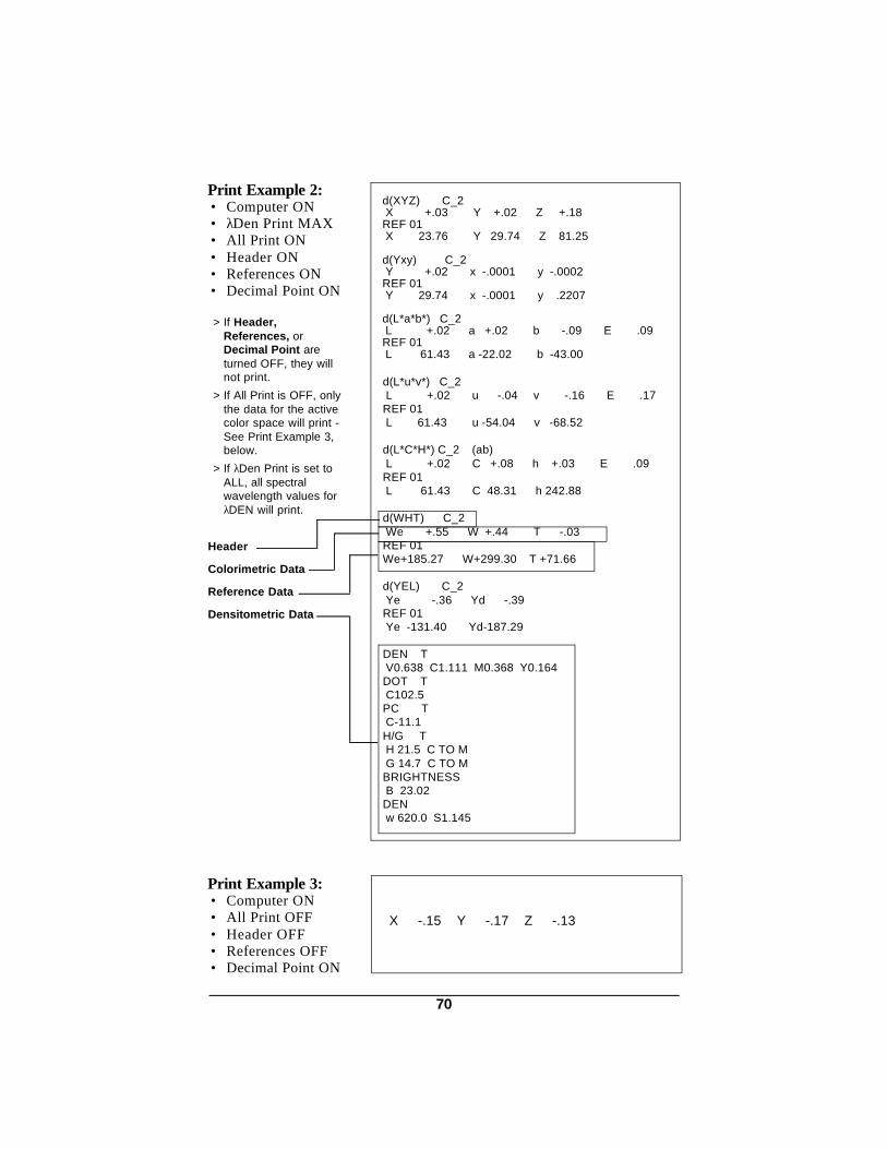
d(XYZ) C_2 X +.03 Y +.02 Z +.18REF 01 X 23.76 Y 29.74 Z 81.25
d(Yxy) C_2 Y +.02 x -.0001 y -.0002REF 01 Y 29.74 x -.0001 y .2207
d(L*a*b*) C_2 L +.02 a +.02 b -.09 E .09REF 01 L 61.43 a -22.02 b -43.00
d(L*u*v*) C_2 L +.02 u -.04 v -.16 E .17REF 01 L 61.43 u -54.04 v -68.52
d(L*C*H*) C_2 (ab) L +.02 C +.08 h +.03 E .09REF 01 L 61.43 C 48.31 h 242.88
d(WHT) C_2 We +.55 W +.44 T -.03REF 01We+185.27 W+299.30 T +71.66
d(YEL) C_2 Ye -.36 Yd -.39REF 01 Ye -131.40 Yd-187.29
DEN T V0.638 C1.111 M0.368 Y0.164DOT T C102.5PC T C-11.1H/G T H 21.5 C TO M G 14.7 C TO MBRIGHTNESS B 23.02 DEN w 620.0 S1.145
Print Example 2:• Computer ON• λDen Print MAX• All Print ON• Header ON• References ON• Decimal Point ON
> If Header,References, orDecimal Point areturned OFF, they willnot print.
> If All Print is OFF, onlythe data for the activecolor space will print -See Print Example 3,below.
> If λDen Print is set toALL, all spectralwavelength values forλDEN will print.
Print Example 3:• Computer ON• All Print OFF• Header OFF• References OFF• Decimal Point ON
Colorimetric Data
Reference Data
Header
Densitometric Data
X -.15 Y -.17 Z -.13
70

SPECTRAL DATAw 400.0 S 27.46w 410.0 S 40.13w 420.0 S 51.43w 430.0 S 61.14w 440.0 S 68.56w 450.0 S 72.43w 460.0 S 73.97w 470.0 S 74.22w 480.0 S 73.23w 490.0 S 71.23w 500.0 S 67.78w 510.0 S 62.51w 520.0 S 55.62w 530.0 S 46.79w 540.0 S 37.28w 550.0 S 27.86w 560.0 S 19.57w 570.0 S 14.16w 580.0 S 10.67w 590.0 S 8.76w 600.0 S 7.82w 610.0 S 7.22w 620.0 S 7.02w 630.0 S 7.10w 640.0 S 7.66w 650.0 S 8.90w 660.0 S 10.09w 670.0 S 10.75w 680.0 S 10.79w 690.0 S 10.00w 700.0 S 8.44
REF 01X 23.76Y 239.74Z 81.25
S 27.46S 40.13S 51.43S 61.14S 68.56S 72.43S 73.97S 74.22S 73.23S 71.23S 67.78S 62.51S 55.62S 46.79S 37.28S 27.86S 19.57S 14.16S 10.67S 8.76S 7.82S 7.22S 7.02S 7.10S 7.66S 8.90S 10.09S 10.75S 10.79S 10.00S 8.44
Print Example 4:• Spectral ON• All Print ON• Header ON• References ON• Decimal Point ON
> If Header,References, orDecimal Point areturned OFF, they willnot print- See PrintExample 5.
> All Print does notaffect the print outwhen Spectral is on.
Print Example 5:• Spectral ON• All Print ON• Header OFF• References OFF• Decimal Point ON
Spectral Data
Reference Data
Headerw/Wavelength
71

11. Changing Apertures
X-Rite has three different aperture kits available for the 938, and theyare listed below.
• 8mm/4mm Aperture Kit P/N 968-100-08• 8mm UV Excluded Aperture Attachment P/N 968-61-08E• 20mm Aperture Kit P/N 968-100-20Each aperture kit includes the aperture, sensor nose, and a specially
designed aperture wrench.
APERTURE INSTALLATION1) Unscrew the two thumb screws [1], then remove the nose piece [2].2) To install the 4mm aperture attachment; screw the 4mm aperture
attachment [3] onto the 8mm aperture [4]. The 4mm apertureattachment must be screwed on finger tight; then advance to Step 6on following page.
To install the 8mm or 20mm aperture; advance to Step 3.
[1]
[4]
[3]
[2]
72

3) Unscrew the existing aperture [5] with the aperture wrench [6].
Note: The aperture wrench tool has two sides, one side fits the 8mmaperture and the other fits the 20mm aperture.
The aperture wrench has two pins that fit into the holes in theaperture.
4) Screw in the new aperture using the aperture wrench.
IMPORTANT! The new aperture must be clean.
5) Attach the new nose piece to the housing with two thumb screws. Note: When you tighten the thumb screws, be sure that the nose pieceis flush against the housing. Gently tighten one screw, then the other.Then finish tightening both screws.IMPORTANT! The new nose piece must be clean.
6) Replace the existing target window [7] with the new target window. Refer to Section 12.4, Target Window Replacement for thisprocedure.
Note: If you switch back and forth between the 4mm and 8mm aperture,it is possible to use the 8mm target window with the 4mm aperture.
7) Change the aperture setting and recalibrate the unit.Refer to Section 7.2, steps 1, 2, & 5a thru 5d for this procedure.
[6]
[5]
[7]
INSERT PINS INTO THE HOLES IN THEAPERTURE, THEN TURNCOUNTERCLOCKWISE TO REMOVE.
73

12. Maintenance
12.1. Troubleshooting The X-Rite 938 is covered by a one year limited warranty (excluding
ni-cad batteries) and should be referred to the factory or authorizedservice center for repair within the warranty period. Attempts to makerepairs within this time frame may void the warranty.
X-Rite provides a factory repair service to their customers. Becauseof the complexity of the circuitry all circuit repairs should be referred tothe factory or an authorized service center.
X-Rite will repair any 938 past warranty. Shipping costs to thefactory or to an authorized service center shall be paid by the customerand the instrument shall be submitted in its original carton, as acomplete unaltered unit.
CAUTION: DO NOT use any ketone solvents to remove inkfrom the unit. This will cause damage to the cover.
IMPORTANT! ALWAYS CHECK TO SEE IF READ LAMP IS WORKING BEFORETROUBLESHOOTING.
-----TROUBLESHOOTING CHART------
A. If a wrong reading exists:1. Recalibrate unit.2. Clean Optics.3 Contact authorized service center.
B. Unit does not turn on. 1. Check for low batteries.2. Contact authorized service center.
C. Display not working.1. Check for low batteries.2. Contact authorized service center.
D. Reading Drifts. 1. Clean Optics.2. Recalibrate unit.3. Contact authorized service center.
E. Unit will not calibrate properly.1. Dirty reference.2. Optics dirty.3. Contact authorized service center.
74

12.2. Optics Cleaning
The target window and optics should be cleaned once a week innormal environments; and more often in dirty or dusty environments.
Target Window 1. Remove dust and lint from target window by wiping it with a clean, lint
free cloth, slightly moistened with water.
Optics 1. Unscrew the two thumb screws [1] and remove the nose piece [2].
Remove dust from aperture with camel hair brush or a camera lenscleaner [3].
2. Blow short bursts of air into the optics opening using a camera lenscleaner (with the brush removed) until all dust is removed. This canbe done with the nose piece removed or attached.
WARNING! Do not use an air can that uses freon as a propellant. Doing so could cause damage to the optics assembly.
[1]
[2][3]
75
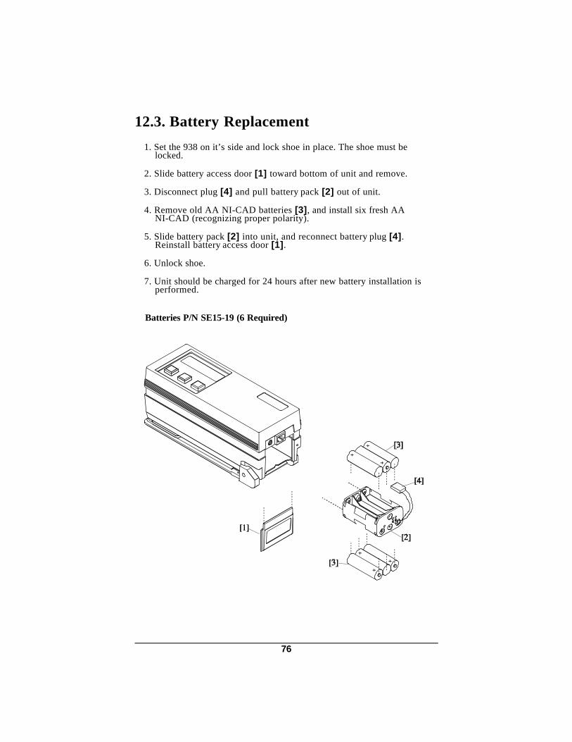
12.3. Battery Replacement
1. Set the 938 on it’s side and lock shoe in place. The shoe must belocked.
2. Slide battery access door [1] toward bottom of unit and remove.
3. Disconnect plug [4] and pull battery pack [2] out of unit.
4. Remove old AA NI-CAD batteries [3], and install six fresh AANI-CAD (recognizing proper polarity).
5. Slide battery pack [2] into unit, and reconnect battery plug [4].Reinstall battery access door [1].
6. Unlock shoe.
7. Unit should be charged for 24 hours after new battery installation isperformed.
Batteries P/N SE15-19 (6 Required)
76

12.4 Target Window Replacement
1. Remove old target window [2] by pushing downward from top of shoe[1].
2. Place the instrument on end and align the target window so that theword "front" runs parallel with the top edge of the shoe [1].
3. Insert one edge (top or bottom) of the new target window [2] in theopening of the shoe [1].
4. Place the other side of the target window [2] in the shoe [1] bysnapping into position.
[1]
[2]
Front Edge
4mm Target Window P/N 968-121-048mm Target Window P/N 968-121-0820mm Target Window P/N 968-121-20
77

12.5. Lamp Replacement
Due to the circuit complexity, alignment procedures, and testequipment required - The read lamp should only be replaced by X-Riteor an authorized X-Rite Service Center.
The lamp is monitored for intensity and failure warnings will bedisplayed if a problem occurs.
The lamp should last approximately one million measurements and iscovered by a one year limited warranty. Refer to the Limited Warrantystatement on page iii.
78

A1 SpecificationsDensitometric MeasuringFunctions: Absolute Minus Paper Notes
DEN DENDOTTRAP Preucil, Brunner,
or NewsPC PCH/G or H/S H/G or H/SBRIGHT per TAPPI T452 om-87λDEN, λDOT λDEN 20nm Incrementsor λREFL
Colorimetric MeasuringFunctions: Absolute Difference Indices:
CIE XYZ ∆(XYZ)X%Y%Z% ∆(X%Y%Z%)CIE Yxy ∆(Yxy)CIE LAB ∆(L*a*b*) ∆E*abHunter LAB ∆(Lab) ∆ECIE LUV ∆(L*u*v*) ∆E*uvCIE LCH ∆(L*C*H*) ∆E*(ab, CMC, or uv space)
Whiteness per ASTM E313Whiteness & Tint per CIEYellowness per ASTM E313Yellowness per ASTM D1925
Display: 2 row by 16 character Supertwist dot matrix LCDMeasuring Geometry: 0°/45°, fiber optic pickup, multi-sensor arrayMeasuring Area: 8.0mm & 4.0mm (20mm optional)Light Source: Gas filled tungsten lamp, approx. 2856°Κ
(corrected for D65 illuminant)Illuminant Types: C, D65, D50, A, F2 (cool white fluorescent),
F7 (broad-band white fluorescent), F11 (TL84), & F12 (Ultralume 3000)
Standard Observers: 2° & 10°Response Types: T, E, I, & A (ANSI PH218, ISO 5/3, DIN 4512)Measurement Range: 0 to 200% reflectance
0 to 2.5DSpectral Range: 400nm - 700nmSpectral Interval: 20nm (15nm bandwidth)Resolution: .01%Inter-Instrument Agreement: 0.20∆E* average (based on average of 12 BCRA tiles)
± .005D or ± .5% whichever is greater (for Status T Responseat SWOP recommended density values)
Short Term Repeatability: 0.05 max ∆E* on a white ceramic (20 measurements)± .005D 0-2.0D± .5% 2.1-2.5D
Warm Up Time: NoneMeasurements per Charge: Approx. 1000 typicalMeasuring Time: Approx. 2 secondsData Interface: Patented Bidirectional RS-232, 300 to 9600 baud
(user selectable), bipolar outputPower Supply: Six rechargeable AA NiCad batteries
7.2v total rated @ 600mAh (included)
79

Charge Time: Approx. 14 hoursAC Adaptor Requirements: 938 90-130VAC, 50-60Hz, 18W Max.
938X 180-260VAC, 50-60Hz, 20W Max.Operating Temp. Range: 50°-104°F (10°-40°C)Storage Temp. Range: -4°-122°F (-20°-50°C)Weight: 2.3 lbs. (1050 grams) Dimensions: 3 3/16" H x 3" W x 7 3/4" L
(81mm H x 76mm W x 197mm L) Accessories Provided: Calibration Standard
Operation ManualReference GuideAC AdaptorCarrying Case
X-Rite reference standards are traceable to the National Institute of Standards andTechnology through Munsell Color Science Laboratory RIT.
This product covered by U.S. Patent 4,591,978 and other patents pending.Specifications and design subject to change without notice.
80

A2 Optional Accessories Part Number
• X-RiteColor® Master . . . . . . . . . . . . . . . . . . . . . . .1242• 4/8mm Aperture Kit . . . . . . . . . . . . . . . . . . . . . . . . . . . . . . . 968-100-08• 20mm Aperture Kit . . . . . . . . . . . . . . . . . . . . . . . . . . . . . . . . 968-100-20• 8mm Aperture Attachment (UV excluding). . . . . . . . . . . 968-61-08E• Spectrophotometer Stand . . . . . . . . . . . . . . . . . . . . . . . . . . 968-80• Security Cable . . . . . . . . . . . . . . . . . . . . . . . . . . . . . . . . . . . . 418-75
• Interconnect cable for Macintosh computerswith 8 pin mini-DIN connector . . . . . . . . . . . . . . . . . . . . . . 418-79
• Modular Interconnect Cable(requires adaptor below) . . . . . . . . . . . . . . . . . . . . . . . . . . . SE108-69
• DB25P DCE (Null Modem) Interface Adaptor. . . . . . . . 418-70• DB25S DCE (Null Modem) Interface Adaptor . . . . . . . 418-71• DB25P DTE (Normal) Interface Adaptor . . . . . . . . . . . . 418-80• DB25S DTE (Normal) Interface Adaptor . . . . . . . . . . . . 418-81• DB9P Interface Adaptor . . . . . . . . . . . . . . . . . . . . . . . . . . . 418-90• DB9S Interface Adaptor . . . . . . . . . . . . . . . . . . . . . . . . . . . 418-91• 4mm Target Window . . . . . . . . . . . . . . . . . . . . . . . . . . . . . . 968-121-04• 8mm Target Window . . . . . . . . . . . . . . . . . . . . . . . . . . . . . . 968-121-08• 20mm Target Window . . . . . . . . . . . . . . . . . . . . . . . . . . . . . 968-121-20
81
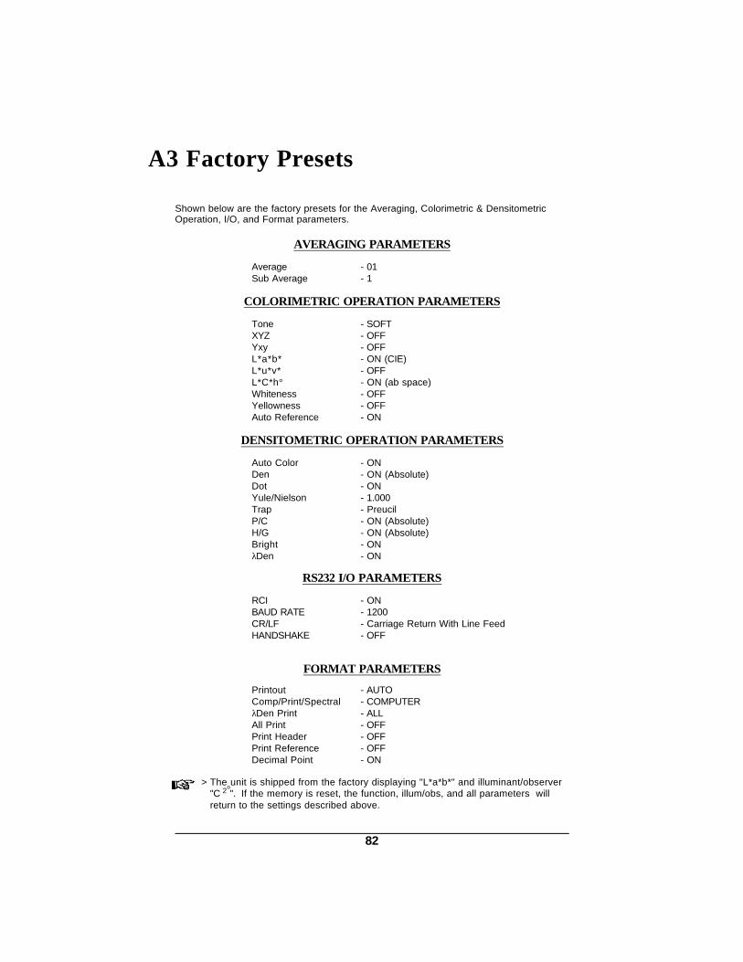
A3 Factory Presets
Shown below are the factory presets for the Averaging, Colorimetric & DensitometricOperation, I/O, and Format parameters.
AVERAGING PARAMETERS
Average - 01Sub Average - 1
COLORIMETRIC OPERATION PARAMETERS
Tone - SOFTXYZ - OFFYxy - OFFL*a*b* - ON (CIE)L*u*v* - OFFL*C*h° - ON (ab space)Whiteness - OFFYellowness - OFFAuto Reference - ON
DENSITOMETRIC OPERATION PARAMETERS
Auto Color - ONDen - ON (Absolute)Dot - ONYule/Nielson - 1.000Trap - PreucilP/C - ON (Absolute)H/G - ON (Absolute)Bright - ONλDen - ON
RS232 I/O PARAMETERS
RCI - ONBAUD RATE - 1200CR/LF - Carriage Return With Line FeedHANDSHAKE - OFF
FORMAT PARAMETERS
Printout - AUTOComp/Print/Spectral - COMPUTERλDen Print - ALLAll Print - OFFPrint Header - OFFPrint Reference - OFFDecimal Point - ON
> The unit is shipped from the factory displaying "L*a*b*" and illuminant/observer"C 2°". If the memory is reset, the function, illum/obs, and all parameters willreturn to the settings described above.
82

A4 Spectrophotometer Stand
X-Rite has an optional mounting fixture available (P/N 968-80). The fixturecan hold items that are a maximum of four inches wide, or two inches to thecenter of the object.
ITEM TO BEMEASURED
SPRING LOADEDHOLDING CLAMP
THE UNIT QUICKLYATTACHES TO THEFIXTURE WITH THUMBSCREW ADJUSTMENTS
HOLDS UNIT CLOSED
83

A5 Color Check
The color check procedure will help you track instrument color performanceto assure measurement accuracy. Initially, the three patches on the standardshould be measured once a day for a period of 10 days to determine thereference values. Thereafter, a periodic check (once a week depending on usage)is all that is required.
Located on the back of the reference standard envelope is a color check label.The reference data should be recorded there for quick reference.
Reference Data Procedure
To obtain reference values: 1) Clean instrument optics and reference standard if necessary.
2) Calibrate instrument according to procedure in operation manual. Note: The reference standard is dramatically affected by smudge marks anddust; and must be kept clean.
3) Select L*a*b* absolute function and desired illuminant/observer. Note: The selected illum/obs must be the same whenever the color check isperformed.
4) Measure the White (1), Blue (2), and Brown (3) patches on the referencestandard.
5) Record the L*a*b* values for each color on a piece of paper.
6) Repeat steps 1-5 for 10 days.
White Blue Brown
84

7) After 10 days average the white, blue, and brown values and enter data in thedesignated place on the color check label.
8) Enter date, illuminant, observer, aperture size, temperature, instrumentmodel, and serial number on color check label. Note: Temperature of the reference standard should be maintained (± 2°C)throughout color check sequence.
Periodic Color Check Procedure
1) Copy reference data located on the color check label to the shaded areas onthe color check record located on the next page.
2) Perform steps 1-4 in reference data procedure.
3) Record the measured white, blue, and brown values and date on the colorcheck record on the next page. Note: You may want to make several copies of the color check record beforeentering any data. This will allow you to have additional pages available whenthey are needed.
4) Compare measured values to the reference values.
• If values are off, clean optics and reference standard and remeasure.
• Consistent L*, a*, or b* differences exceeding .30 (or obvious trends awayfrom the reference data) may require the unit to be serviced. ContactX-Rite or authorized service center if this is the case.
• Always verify color performance with the same aperture size, illum/obs,and temperature.
85

COLOR CHECK RECORDDate: Illuminant: Observer:Temperature: Aperture Size: Model-S/N:
Reference White Blue BrownValues L* a* b* L* a* b* L* a* b*
Date
86


P/N 938-500 Rev. AA-5/2/03
X-Rite, Incorporated - World Headquarters 3100 44th Street S.W. • Grandville, Michigan 49418 • USA www.x-rite.com Tel: 1-888-826-3042 • Fax: 1-888-826-3043 or (616)-534-0726 International Tel: 1-888-826-3039 or (616) 534-7663 • Fax: (616) 534-0726 X-Rite GmbH Stollwerckstraße 32 • 51149 Köln • Germany Tel: (49) 22 03-91 45 0 • Fax: (49) 22 03-91 45 19 X-Rite GmbH Sochorova 705 • CZ-682 • 11 Vyskov • Czech Republic Tel: (420) 507-328197 • Fax: (420) 507-328138 X-Rite Asia Pacific Ltd. Room 808-10 • Kornhill Metro Tower • 1 Kornhill Road • Quarry Bay Hong Kong • Tel: (852) 2-568-6283 • Fax: (852) 2-885-8610 X-Rite Ltd. The Acumen Centre • First Avenue Poynton, Cheshire • England Tel: 44-0-1625-871100 • Fax: 44-0-1625-871444 X-Rite Méditerranée Parc du moulin de Massy • 35, rue du Saule Trapu • 91300 Massy • France Tel: 33-1-69.53.66.20 • FAX 33-1-69.53.00.52 X-Rite Italy Srl Via per Caronno, 35 21040 Origgio (Va) • Italy Tel. 0039 02 96734266 • Fax. 0039 02 96730681 X-Rite Asia Pacific Limited - Japan Office No.1 Baba Bldg. • 3-19-18 Shibaura, Minato-ku, Tokyo • 108-0023 Japan Tel: +81-3-5439-5971 • Fax: +81-3-5439-5972 X-Rite Asia Pacific Ltd. - Singapore Representative Office 14 Science Park Drive • #02-04 The Maxwell Singapore Science Park • Singapore 118226 Tel: + 65 7788-773 • Fax: + 65 7788-645