spectral response and far-field pattern of a dipole nano-antenna on metamaterial substrates having...
TRANSCRIPT
Optics Communications 284 (2011) 1429–1434
Contents lists available at ScienceDirect
Optics Communications
j ourna l homepage: www.e lsev ie r.com/ locate /optcom
Spectral response and far-field pattern of a dipole nano-antenna on metamaterialsubstrates having near-zero and negative indices of refraction
Francisco Javier González a, Javier Alda b,⁎a Coordinación para la Innovación y la Aplicación de la Ciencia y la Tecnología, Universidad Autónoma de San Luis Potosí, SLP, Mexicob Applied Optics Complutense Group, University Complutense of Madrid, School of Optics, Ave. Arcos de Jalón, 118, 28037 Madrid, Spain
⁎ Corresponding author. Tel.: +34 91 394 6874; fax:E-mail address: [email protected] (J. Alda).
0030-4018/$ – see front matter © 2010 Elsevier B.V. Aldoi:10.1016/j.optcom.2010.10.072
a b s t r a c t
a r t i c l e i n f oArticle history:Received 3 February 2010Received in revised form 1 August 2010Accepted 22 October 2010
In this work the resonance, frequency response, and far-field patterns of an optical nano-antenna placed on aninterface between air and a metamaterial substrate is obtained through finite element calculations. Themetamaterial is characterized by an effective, macroscopic index of refraction which can take negative andnear-zero values, or by published values of the effective permittivity and permeability for metamaterials. Theresults show that the resonant wavelength and response can be fitted to analytical functions that are evenfunctions of the index of refraction, this is consistent with the knowledge that negative indices of refractionallows for wave propagation in the same magnitude but opposite direction observed with positive indices ofrefraction. The simulations also show that substrates with near-zero index of refraction will enhance theantenna response by 62% compared to substrates with nN1. Lossy metamaterials are also considered in thesimulations. The far-field pattern of the antenna, obtained through a near-field to far-field transformation,behaves the same independently of the sign of the index of refraction, also the far-field pattern for theemission towards near-zero substrates is nearly constant and independent of the angle for the evaluatedangular range.
+34 91 394 6880.
l rights reserved.
© 2010 Elsevier B.V. All rights reserved.
1. Introduction
In a paper published in 1968 [1], Veselago predicted thatelectromagnetic plane waves in a medium having simultaneouslynegative permittivity and permeability would propagate in a directionopposite to that of the flow of energy, this effectively translates in themedium having a negative index of refraction [2]. Metamaterials areartificially engineered structures that have properties, such as anegative refractive index, not attainable with naturally occurringmaterials [3]. Low-index and zero-index metamaterials have beenalso synthesized using frequency selective surfaces [4], and used forelectromagnetic cloaking [5] and to concentrate the energy radiatedby a source embedded in a slab of zero-index metamaterial andimprove the directivity of dual polarization/dual band patch antennas[6]. Snell law implies that, when the radiation is arriving to theinterface from a near-zero-index medium, the radiation will berefracted towards the air in a direction very close to the normal (loweris the optical index; closer is the direction to the normal) [7]. Thisapproach does not take into account some other issues about thefeasibility of the materials and energy budget that have been underdiscussion since the appearance of these innovative ideas [8].
Metamaterials producing near-zero and negative indices ofrefraction are typically proposed as complex geometrical arrange-ments of electromagnetic resonant structures and waveguides. In aprevious contribution [9] we have analyzed how the near field isaffected by the intimate structure of the metamaterial conforming anano-cavity that, due to the presence of defects, cannot be easilyrepresented by an effective index. In this contribution, as far as we areinterested in the spectral response and the far-field pattern of a nano-antenna, our approach is quite different. Nowwe have not consideredthe detailed structure of the metamaterials and we have describedthem as a homogeneous material having a macroscopic index ofrefraction, n. This index of refraction of the metamaterial can beconsidered as an equivalent, or effective, index of refraction whichdescribes the overall optical properties ofmetamaterials [10,11]. It hasbeen also used in other areas of optics, for example when substitutingthe complex structure of a multilayer by an interface separating theouter media from an equivalent index media, this equivalent indexcan be used to describe the properties of the multilayer [12]. In thiscontribution the effect of low-index, zero-index and negative-indexsubstrates on the performance of nano-antennas is evaluated by finiteelement method (FEM) simulations using COMSOL Multiphysics.
Section 2 of this paper analyzes the resonance of a dipole antennalocated on an interface separating air from a substrate having an indexof refraction that can be, positive, close to zero, and also negative. Thelocation of the wavelength of resonance and the value of the max-imum response of the dipole antenna as a function of the index of

2
3
4x 10-15
pons
e (A
)
1430 F.J. González, J. Alda / Optics Communications 284 (2011) 1429–1434
refraction of the substrate is analyzed. Section 3 deals with the lossesand the frequency response of antennas on metamaterial substrates.Section 4 is focused on the calculation of the far-field pattern of thedipole antenna when this is located on a substrate having near-zero,or negative index of refraction. The modulus and phase electric-fielddistribution on the antenna plane is calculated and a Fourier trans-form is made to obtain the far-field pattern. Finally, Section 5 sum-marizes the main conclusions of this paper.
1.5 2 2.5 3 3.5 4 4.5 50
1
λ (microns)
Res
Fig. 2. Response of a 1 μm dipole antenna in air. The circle represents the maximumresponse, Rmax, which is obtained for a given wavelength, λmax.
2. Resonance of nano-antennas on metamaterial substrates
In order to obtain the response of nano-antennas on metama-terial substrates finite element simulations were performed bylaunching a plane wave with an electric-field amplitude set to 1 V/mand calculating the induced current in the nano-antenna, as a functionof the plane wave's wavelength, by integrating the surface currentdensity over the antenna cross-section at its geometrical center, whichcan be considered the feed point of the antenna. This feed point ofthe antenna is usually the location of the transducer elementswhen optical antennas are coupled to bolometric or rectifying junc-tions [13,14]. Matched boundary conditions were used in the FEMsimulations and tetrahedral elements were used to discretize thecomputational domain. The substrate material is characterized by anequivalent index of refraction, n. In this section since we are onlyinterested in the nano-antenna at resonance a not absorbent materialwith a purely real equivalent index of refraction was considered forthe metamaterial substrate. The nano-antenna was simulated on theinterface between the metamaterial and the air (see Fig. 1). Thesimulated antenna is a 1 μm-long dipole having a width of 100 nmand a thickness of 100 nm. The material of the antenna is gold and itsindex of refraction is taken as a complex number that varies with the
Fig. 1. Geometrical arrangement of a dipole on an interface between air (n=+1) and asubstrate with a variable index of refraction.
wavelength. Therefore, the losses due to the metal of the antenna aretaken into account.
Fig. 2 shows the spectral response of a 1 μm-long dipole antennaimmersed in air. From this graph we are mainly interested in themaximum response which would give us the main resonantwavelength of the dipole. In this paper the calculation of the responseof the dipole antenna has been done by selecting several values ofthe index of refraction of the substrate, n. These values are given inTable 1.
Fig. 3 shows the value of the resonance wavelength as a functionof the index of refraction. First of all we can see that the location of theresonance wavelength is symmetric with respect to the index of refrac-tion, this data can be empirically fitted to the following hyperbolicfunction,
λ max nð Þ = λ0
ffiffiffiffiffiffiffiffiffiffiffiffiffiffiffiffiffiffiffiffiffiffiffiffiffi1 +
nnR
� �2s
; ð1Þ
being λ0 the value of λmax when n=0, and nR a parameter describinga limit in the value of the index of refraction where the dependenceis not linear. The thin solid lines plotted in Fig. 3 shows the lineardependence that cannot be applied for n values below nR. The fittingproduces λ0=1.72 μm, and nR=0.96. If the dipole antenna wasimmersed in air and behaving ideally, then the resonant wavelengthwould be twice the length of the dipole, i.e., λmax=2 μm. However, atinfrared frequencies thematerial properties of gold are those of a non-perfect conductor [15], this fact shifts the resonant wavelength
Table 1Values of the index of refraction of the substrate used in the simulations.
nN0 nb0
|n|≥1 4 −43 −32 −21.5 −11
0.1b | n |b1 0.5 −0.50.25 −0.250.125 −0.125
Near-zero index, |n|≤0.1 0.1 −0.10.0625 −0.06250.0313 −0.03130.0156 −0.01560.01 −0.01
-4 -3 -2 -1 0 1 2 3 40
1
2
3
4
5
6
7
8
index of refraction
λ m
ax (
mic
rons
)
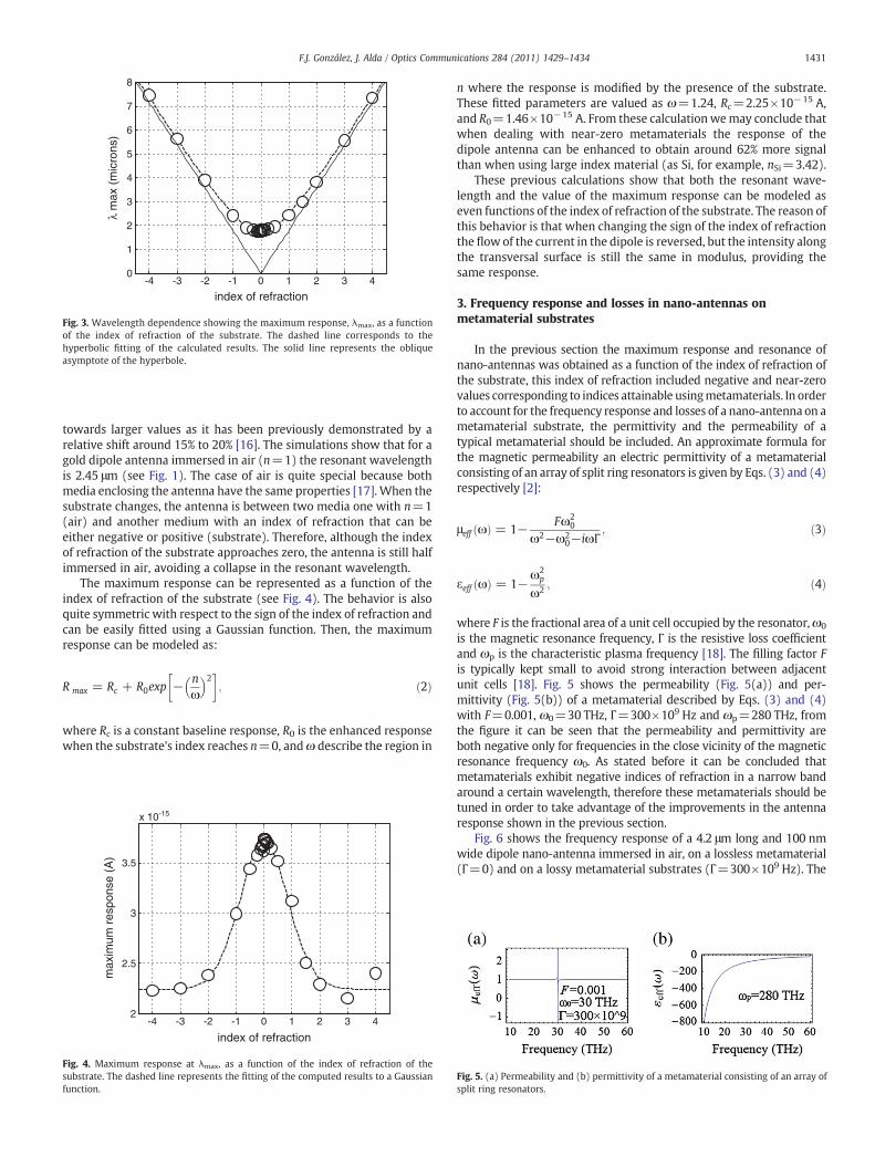
Fig. 3. Wavelength dependence showing the maximum response, λmax, as a functionof the index of refraction of the substrate. The dashed line corresponds to thehyperbolic fitting of the calculated results. The solid line represents the obliqueasymptote of the hyperbole.
1431F.J. González, J. Alda / Optics Communications 284 (2011) 1429–1434
towards larger values as it has been previously demonstrated by arelative shift around 15% to 20% [16]. The simulations show that for agold dipole antenna immersed in air (n=1) the resonant wavelengthis 2.45 μm (see Fig. 1). The case of air is quite special because bothmedia enclosing the antenna have the same properties [17]. When thesubstrate changes, the antenna is between two media one with n=1(air) and another medium with an index of refraction that can beeither negative or positive (substrate). Therefore, although the indexof refraction of the substrate approaches zero, the antenna is still halfimmersed in air, avoiding a collapse in the resonant wavelength.
The maximum response can be represented as a function of theindex of refraction of the substrate (see Fig. 4). The behavior is alsoquite symmetric with respect to the sign of the index of refraction andcan be easily fitted using a Gaussian function. Then, the maximumresponse can be modeled as:
R max = Rc + R0exp − nω
� �2� �
; ð2Þ
where Rc is a constant baseline response, R0 is the enhanced responsewhen the substrate's index reaches n=0, andω describe the region in
-4 -3 -2 -1 0 1 2 3 42
2.5
3
3.5
x 10-15
index of refraction
max
imum
res
pons
e (A
)
Fig. 4. Maximum response at λmax, as a function of the index of refraction of thesubstrate. The dashed line represents the fitting of the computed results to a Gaussianfunction.
n where the response is modified by the presence of the substrate.These fitted parameters are valued as ω=1.24, Rc=2.25×10⁻¹⁵ A,and R0=1.46×10⁻¹⁵ A. From these calculationwemay conclude thatwhen dealing with near-zero metamaterials the response of thedipole antenna can be enhanced to obtain around 62% more signalthan when using large index material (as Si, for example, nSi=3.42).
These previous calculations show that both the resonant wave-length and the value of the maximum response can be modeled aseven functions of the index of refraction of the substrate. The reason ofthis behavior is that when changing the sign of the index of refractionthe flow of the current in the dipole is reversed, but the intensity alongthe transversal surface is still the same in modulus, providing thesame response.
3. Frequency response and losses in nano-antennas onmetamaterial substrates
In the previous section the maximum response and resonance ofnano-antennas was obtained as a function of the index of refraction ofthe substrate, this index of refraction included negative and near-zerovalues corresponding to indices attainable usingmetamaterials. In orderto account for the frequency response and losses of a nano-antenna on ametamaterial substrate, the permittivity and the permeability of atypical metamaterial should be included. An approximate formula forthe magnetic permeability an electric permittivity of a metamaterialconsisting of an array of split ring resonators is given by Eqs. (3) and (4)respectively [2]:
μeff ωð Þ = 1− Fω20
ω2−ω20−iωΓ
; ð3Þ
εeff ωð Þ = 1−ω2
p
ω2 ; ð4Þ
where F is the fractional area of a unit cell occupied by the resonator,ω0
is the magnetic resonance frequency, Γ is the resistive loss coefficientand ωp is the characteristic plasma frequency [18]. The filling factor Fis typically kept small to avoid strong interaction between adjacentunit cells [18]. Fig. 5 shows the permeability (Fig. 5(a)) and per-mittivity (Fig. 5(b)) of a metamaterial described by Eqs. (3) and (4)with F=0.001, ω0=30 THz, Γ=300×109 Hz and ωp=280 THz, fromthe figure it can be seen that the permeability and permittivity areboth negative only for frequencies in the close vicinity of the magneticresonance frequency ω0. As stated before it can be concluded thatmetamaterials exhibit negative indices of refraction in a narrow bandaround a certain wavelength, therefore these metamaterials should betuned in order to take advantage of the improvements in the antennaresponse shown in the previous section.
Fig. 6 shows the frequency response of a 4.2 μm long and 100 nmwide dipole nano-antenna immersed in air, on a lossless metamaterial(Γ=0) and on a lossy metamaterial substrates (Γ=300×109 Hz). The
Fig. 5. (a) Permeability and (b) permittivity of a metamaterial consisting of an array ofsplit ring resonators.
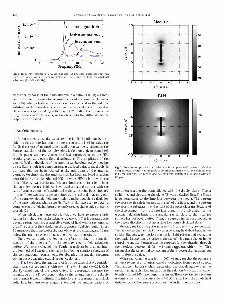
Fig. 6. Frequency response of a 4.2 μm long and 100 nm wide dipole nano-antennaimmersed in air, on a lossless metamaterial (Γ=0) and on lossy metamaterialsubstrates (Γ=300×109 Hz).
1432 F.J. González, J. Alda / Optics Communications 284 (2011) 1429–1434
frequency response of the nano-antenna in air shown in Fig. 6 agreeswith previous experimental measurements of antennas of the samesize [16], when a lossless metamaterial is introduced as the antennasubstrate in the simulation a reduction of a factor of 2.5 is observed inthe antenna response, along with a slight (2%) shift of the resonance tolonger wavelengths, for a lossy metamaterial a further 40% reduction inresponse is observed.
Fig. 7. Modulus and phase maps of the complex amplitude of the electric-field y-component, Ey, obtained at the plane of the antenna when n=1. The dipole antennais placed along the y direction and having a total length of 1 μm and a width of0.1 μm.
4. Far-field patterns
Antenna theory usually calculates the far-field radiation by con-sidering the currents built on the antenna structure [19]. In optics, thefar-field pattern of an amplitude distribution can be calculated as theFourier transform of the complex electric field on a given plane [20].In this paper we have chosen this last approach using the FEMresults given as electric-field distributions. The amplitude of theelectric field on the plane of the antenna can be obtained by injectingan oscillating high-frequency current at the feed point of the dipole. Inour case this has been located at the mid-point of the antennaelement. For simplicity the antenna itself has been modeled as havingzero thickness, l μm length, and 100 nm wide. FEM only provides themap of the real-valued electric-field amplitude vector. In order to havethe complex electric field we have used a second current with thesame frequency than the first, injected at the samepoint, but shiftedπ/2in time. These two results are combined as the real and imaginary partof the complex electric-field amplitude to make possible a calculationof the amplitude and phase (see Fig. 7). A similar approach to obtain acomplex electricfield has been previously used to characterize photoniccrystals [21].
When calculating these electric fields we have to move a littlefarther from the antenna plane, but very close to it. This is because at theantenna plane we have a negligible value of field within the antennaarea. The plane for the calculation of the electric-field distribution is just10 nmabove the interface for the case of the air propagation, and 10 nmbelow the interface when propagating towards the substrate.
Then, we can apply the Fourier transform to obtain the angulardiagram of the antenna from the complex electric field calculatedbefore. We have evaluated this Fourier transform by a direct inte-gration method instead of the handy fast Fourier transform because ofthe computational requirements for obtaining the angular spectrumwithin the propagating spatial frequency domain.
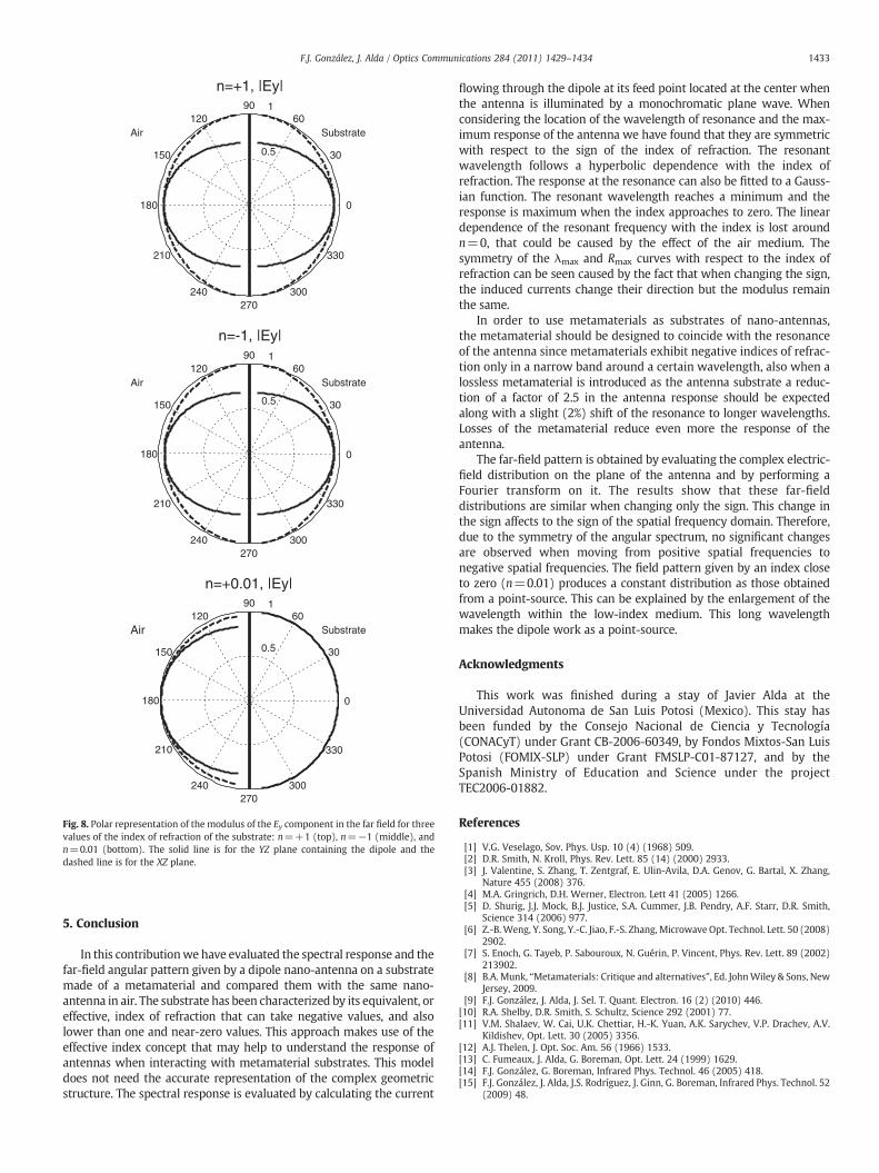
In Fig. 8 we show the angular plot for three cases that we considersignificant, corresponding with n=+1, n=−1, and n=0.01. Onlythe Ey component of the electric field is represented because themagnitude of the Ex component, due to the orientation of the dipolehas a much lower amplitude. The interface is represented as a thicksolid line. In these polar diagrams we plot the angular pattern of
the antenna along the plane aligned with the dipole, plane YZ, as asolid line, and also along the plane XZ with a dashed line. The Z axisis perpendicular to the interface between the media. The patterntowards the air side is located at the left of the figure, and the patterntowards the substrate is at the right of the polar diagram. Because ofthe displacement from the interface plane in the calculation of theelectric-field distribution, the angular region close to the interfacesurface has not been plotted. Then, the zero emission observed alongthe dipole direction is not accessible from our calculated data.
We may see that the pattern for n=+1, and n=−1, are identical.This is due to the fact that the corresponding field distributions aresimilar. Besides, when performing the far-field pattern and evaluatingthe spatial frequencies, a change in the sign of n is a mere change in thesign of the angular frequency, as it is expected for the refraction throughthe interfaces between air (n=+1) and a medium with n=−1. Thismeans that the tangential component of the
→k vector changes sign, but
not its absolute value.When analyzing the case for n=0.01 wemay see that the pattern is
almost the one of a spherical wavefront obtained from a point-source.This happens because when calculating the wavelength within themedia having such a low index using the relation λ=λ0/n, this wave-length is scaled 100 times larger than in air. Therefore, the field patternis coming from a small source about λ/200 in size. Then, the dipole fielddistribution can be seen as a point-source within the substrate.
0.5
1
30
210
60
240
90
270
120
300
150
330
0081
n=+1, |Ey|
SubstrateAir
0.5
1
30
210
60
240
90
270
120
300
150
330
180 0
n=-1, |Ey|
SubstrateAir
0.5
1
30
210
60
240
90
270
120
300
150
330
180 0
n=+0.01, |Ey|
SubstrateAir
Fig. 8. Polar representation of the modulus of the Ey component in the far field for threevalues of the index of refraction of the substrate: n=+1 (top), n=−1 (middle), andn=0.01 (bottom). The solid line is for the YZ plane containing the dipole and thedashed line is for the XZ plane.
1433F.J. González, J. Alda / Optics Communications 284 (2011) 1429–1434
5. Conclusion
In this contributionwe have evaluated the spectral response and thefar-field angular pattern given by a dipole nano-antenna on a substratemade of a metamaterial and compared them with the same nano-antenna in air. The substrate has been characterized by its equivalent, oreffective, index of refraction that can take negative values, and alsolower than one and near-zero values. This approach makes use of theeffective index concept that may help to understand the response ofantennas when interacting with metamaterial substrates. This modeldoes not need the accurate representation of the complex geometricstructure. The spectral response is evaluated by calculating the current
flowing through the dipole at its feed point located at the center whenthe antenna is illuminated by a monochromatic plane wave. Whenconsidering the location of the wavelength of resonance and the max-imum response of the antenna we have found that they are symmetricwith respect to the sign of the index of refraction. The resonantwavelength follows a hyperbolic dependence with the index ofrefraction. The response at the resonance can also be fitted to a Gauss-ian function. The resonant wavelength reaches a minimum and theresponse is maximum when the index approaches to zero. The lineardependence of the resonant frequency with the index is lost aroundn=0, that could be caused by the effect of the air medium. Thesymmetry of the λmax and Rmax curves with respect to the index ofrefraction can be seen caused by the fact that when changing the sign,the induced currents change their direction but the modulus remainthe same.
In order to use metamaterials as substrates of nano-antennas,the metamaterial should be designed to coincide with the resonanceof the antenna since metamaterials exhibit negative indices of refrac-tion only in a narrow band around a certain wavelength, also when alossless metamaterial is introduced as the antenna substrate a reduc-tion of a factor of 2.5 in the antenna response should be expectedalong with a slight (2%) shift of the resonance to longer wavelengths.Losses of the metamaterial reduce even more the response of theantenna.
The far-field pattern is obtained by evaluating the complex electric-field distribution on the plane of the antenna and by performing aFourier transform on it. The results show that these far-fielddistributions are similar when changing only the sign. This change inthe sign affects to the sign of the spatial frequency domain. Therefore,due to the symmetry of the angular spectrum, no significant changesare observed when moving from positive spatial frequencies tonegative spatial frequencies. The field pattern given by an index closeto zero (n=0.01) produces a constant distribution as those obtainedfrom a point-source. This can be explained by the enlargement of thewavelength within the low-index medium. This long wavelengthmakes the dipole work as a point-source.
Acknowledgments
This work was finished during a stay of Javier Alda at theUniversidad Autonoma de San Luis Potosi (Mexico). This stay hasbeen funded by the Consejo Nacional de Ciencia y Tecnología(CONACyT) under Grant CB-2006-60349, by Fondos Mixtos-San LuisPotosi (FOMIX-SLP) under Grant FMSLP-C01-87127, and by theSpanish Ministry of Education and Science under the projectTEC2006-01882.
References
[1] V.G. Veselago, Sov. Phys. Usp. 10 (4) (1968) 509.[2] D.R. Smith, N. Kroll, Phys. Rev. Lett. 85 (14) (2000) 2933.[3] J. Valentine, S. Zhang, T. Zentgraf, E. Ulin-Avila, D.A. Genov, G. Bartal, X. Zhang,
Nature 455 (2008) 376.[4] M.A. Gringrich, D.H. Werner, Electron. Lett 41 (2005) 1266.[5] D. Shurig, J.J. Mock, B.J. Justice, S.A. Cummer, J.B. Pendry, A.F. Starr, D.R. Smith,
Science 314 (2006) 977.[6] Z.-B.Weng, Y. Song, Y.-C. Jiao, F.-S. Zhang, Microwave Opt. Technol. Lett. 50 (2008)
2902.[7] S. Enoch, G. Tayeb, P. Sabouroux, N. Guérin, P. Vincent, Phys. Rev. Lett. 89 (2002)
213902.[8] B.A. Munk, “Metamaterials: Critique and alternatives”, Ed. JohnWiley & Sons, New
Jersey, 2009.[9] F.J. González, J. Alda, J. Sel. T. Quant. Electron. 16 (2) (2010) 446.
[10] R.A. Shelby, D.R. Smith, S. Schultz, Science 292 (2001) 77.[11] V.M. Shalaev, W. Cai, U.K. Chettiar, H.-K. Yuan, A.K. Sarychev, V.P. Drachev, A.V.
Kildishev, Opt. Lett. 30 (2005) 3356.[12] A.J. Thelen, J. Opt. Soc. Am. 56 (1966) 1533.[13] C. Fumeaux, J. Alda, G. Boreman, Opt. Lett. 24 (1999) 1629.[14] F.J. González, G. Boreman, Infrared Phys. Technol. 46 (2005) 418.[15] F.J. González, J. Alda, J.S. Rodríguez, J. Ginn, G. Boreman, Infrared Phys. Technol. 52
(2009) 48.

1434 F.J. González, J. Alda / Optics Communications 284 (2011) 1429–1434
[16] C. Fumeaux, M.A. Gritz, I. Codreanu, W.L. Schaich, F.J. González, G.D. Boreman,Infrared Phys. Technol. 41 (2000) 471.
[17] J. Alda, C. Fumeaux, M. Gritz, D. Spencer, G. Boreman, Infrared Phys. Technol. 41(2000) 1.
[18] G. Shvets, Y.A. Urzhumov, J. Opt. A Pure Appl. Opt. 8 (2006) S122.
[19] C.A. Balanis, Antenna Theory: Analysis and Design, 3er. edJohnWiley & Sons, NewJersey, USA, 20058 chapter 3.
[20] J.W. Goodman, Introduction to Fourier Optics, 3rd edRoeberts & CompanyPublisher, Greenwood Village, CO (USA), 20058 chapter 4.
[21] J.M. Lopez-Alonso, J.M. Rico-Garcia, J. Alda, Opt. Express 12 (2004) 2176.