spectral monte carlo simulation of collimated solar ...coe papers/jp_107.pdf · spectral monte...
TRANSCRIPT

Spectral Monte Carlo simulation of collimatedsolar irradiation transfer in a water-filledprismatic louverYAOMIN CAI AND ZHIXIONG GUO*Department of Mechanical and Aerospace Engineering, Rutgers, The State University of New Jersey, Piscataway, New Jersey 08854, USA*Corresponding author: [email protected]
Received 9 February 2018; revised 15 March 2018; accepted 15 March 2018; posted 16 March 2018 (Doc. ID 322830); published 13 April 2018
The Monte Carlo model was developed to simulate the collimated solar irradiation transfer and energy harvest ina hollow louver made of silica glass and filled with water. The full solar spectrum from the air mass 1.5 databasewas adopted and divided into various discrete bands for spectral calculations. The band-averaged spectral proper-ties for the silica glass and water were obtained. Ray tracing was employed to find the solar energy harvested by thelouver. Computational efficiency and accuracy were examined through intensive comparisons of different bandpartition approaches, various photon numbers, and element divisions. The influence of irradiation direction onthe solar energy harvest efficiency was scrutinized. It was found that within a 15° polar angle of incidence, theharvested solar energy in the louver was high, and the total absorption efficiency reached 61.2% under normalincidence for the current louver geometry. © 2018 Optical Society of America
OCIS codes: (350.6050) Solar energy; (000.4430) Numerical approximation and analysis; (010.1030) Absorption; (010.5620)
Radiative transfer; (160.4760) Optical properties.
https://doi.org/10.1364/AO.57.003021
1. INTRODUCTION
The spectrum-integrated irradiance corresponds to a solarconstant of 1366.1 W∕m2 above the Earth’s atmosphere [1].Although the amount of solar irradiation on the Earth’s surfaceis enormous, approximately 3 × 1024 joules per year, most of itremains unused, while we keep depleting traditional fossil fuels[2]. The annual installation capacity of solar photovoltaic facili-ties has continuously seen a significant increase worldwide inrecent years [3].
There is a pressing need for green energy and sustainability,and next-generation net-zero energy buildings. The U.S.Department of Energy [4] calculates that the existing buildingstock in the United States accounts for approximately 41% ofnational energy consumption, and approximately 58% is usedfor lighting and space heating, making the building sector thelargest energy consumer. Abundant solar energy can providenatural lighting as well as heating, and thus, well-utilized solarenergy will lead to energy savings. At present, the majority ofgreen facilities utilizing solar energy only perform either forheating or power generation, making use of only several certainbands of solar irradiation. Most often seen examples are solarwater heaters, solar photovoltaic cells, and concentrating solarpower plants. It is necessary to develop new technologies to takefull advantage of the whole solar spectrum energy.
Windows in the United States consume 30% of overallbuilding heating and cooling loads [4], representing an annualimpact of 4.1 quadrillion BTU (quads) of primary energy.Before the industrial revolution, the Sun was the major sourceof lighting and heating. How to efficiently utilize the solarirradiation from windows has gained new attention. Dr.Madamopoulos at City College of New York initially proposedthe idea of prismatic louver to improve daylighting quality[5,6]. Later, he and one current author, Dr. Guo, proposedtogether the nanofluid-filled hollow prismatic louver forimproved daylighting and enhanced solar energy harvestingsimultaneously [7].
The concept of the proposed glass louver [see Fig. 1(a)] in aglazing system is based on the ability of a prism to deviate in-cident light. The collimated solar irradiation will be redirectedby the louver to ceiling and reflected diffusely to room space forillumination. This will eliminate the “glare effect,” thus improv-ing the natural lighting quality and increasing occupants’ com-fort. The concern of the “rainbow effect” in an individuallouver because of material dispersion to different colors of lightcan be minimized by installing many louvers in a stacked con-figuration in practical applications. Further, multiple reflectionof light inside the louver will also lessen the dispersion effect.Enhanced daylight has the potential to reduce the energy
Research Article Vol. 57, No. 12 / 20 April 2018 / Applied Optics 3021
1559-128X/18/123021-10 Journal © 2018 Optical Society of America

consumption due to artificial lighting for both residential andcommercial buildings. On the other hand, the liquid/nanofluidfilled and flowing inside the hollow louver will absorb the solarenergy. The harvested solar energy could be used to replacewater heaters or be stored for other purposes. The present studyfocuses on investigating the solar irradiation transfer and energyharvest using water inside a glass louver.
The Monte Carlo (MC) model is a useful method for sim-ulating the laser and solar radiation transfer in complex systems[8,9]. It was applied to thermal radiation problems in the early1960s [10,11]. Advantages in using MC include easy handlingof complicated physical processes and conditions based on stat-istical distributions, and easy coding without having to solvecomplicated governing equations. The MC simulation of radi-ative energy redistribution in a system is achieved via tracing alarge number of photon energy bundles from the point of emis-sion till the point of extinction. There are a number of excellentpapers [12–16] in the literature on MC methods for radiationtransfer in participating media under various conditions. In thepresent solar-louver system, the solar irradiation on the louver ishighly spectral, and the glass and water absorption and refrac-tive index variations are all spectral. Hence, a MC modelingwith appropriate spectral properties incorporating reflection,refraction, absorption, and scattering is necessary.
The solar spectrum spans a wide range from 100 nm to1 mm. In terms of energy significance, the sunlight at theEarth’s surface is approximately 52%–55% infrared (IR; above700 nm), 42%–43% visible (VIS; 400–700 nm), and 3%–5%ultraviolet (UV; below 400 nm), calculated from reference airmass (AM) 1.5 spectra [17]. Line-by-line spectral calculationsare extremely time demanding, even with deterministic meth-ods, not to mention time-consuming MC methods. Therefore,it is important to consider band-average techniques, based onthe significance and difference of various bands. Hoyt [18] cal-culated the solar global insolation using the one-band graymodel. Gueymard [19] utilized a two-band model to calculatethe sky solar irradiance, illuminance, and photosynthetically ac-tive radiation. Escobedo et al. [20] used hourly and daily radio-metric data to establish several empirical models for predictingthe fractions of three bands, including visible (VIS), photosyn-thetically active (PAR), and near-infrared (NIR). Bird andRiordan [21] provided a simple model for calculating spectralsolar irradiance on tilted surfaces, producing terrestrialspectra between 300 nm and 4,000 nm with a resolution of
approximately 10 nm. Nevertheless, it would be very usefulto establish a band partition model that would be computation-ally efficient and accurate for calculating the solar irradiationtransfer in glass–water systems.
The incident angle of solar irradiation on a window dependson many factors, such as the zenith angle, season, time, loca-tion, and window direction and orientation. Lave and Jan [22]discussed the global irradiance for different longitudes andlatitudes in the continental United States. Yan et al. [23]analyzed different tilt angles using yearlong record data inBrisbane. Rowlands et al. [24] investigated the optimal tilt an-gle and azimuth for a photovoltaic panel in Ontario, Canada.Papanicolaou et al. [25] numerically studied the effect of incli-nation angle on natural convective heat transfer in air inside anasymmetric, greenhouse-type solar still. Tang andWu [26] pro-posed a simple mathematical procedure for estimation of theoptimal tilt angle of a collector based on the monthly horizontalradiation, and they plotted a contour map of the optimal tiltangle for the south-facing collectors in China. Although thecurrently proposed louver could be adjusted to face the solarirradiation to harvest the largest amount of solar irradiationin practical deployment, further studies are still needed to ex-amine the influence of the incidence angle of solar irradiation.
2. SIMULATION METHOD
The physical model discussed in this study is a device consistingof a series of transparent louvers that can be installed on oneside of a window to change the direction of collimated sunlightto provide natural lighting deeper in the room, as well as toabsorb the IR part in solar radiation to heat the water inside.The cross section of the prismatic louver is an equilateral tri-angle, which is an assembly of three pieces of uniform silicaglass, each 0.125 inches thick (τ) and 3 inches wide (W).The height (H) of the triangle is 0.5
ffiffiffi3
pW. A brief illustration
of the louver cross section is given in Fig. 1(a). As the louver isvery long, its end effect is generally negligible. The only situa-tion that the end effect cannot be neglected is that both θ and∅ approach 90°, which consists of a very small solid angle ofincidence. In such a small solid angle, the solar incidence isalmost negligible as cos θ approaches to zero. Thus, a 2Dgeometry is considered in this study. However, the MC ray trac-ing should be performed in 3D with the y direction being in-finite and the y value at each reflection/refraction/scatteringpoint being recoiled back to zero.
Figure 2 shows the flowchart for tracing one photon bundlein our MC modelling. A photon bundle is initiated from a po-sition (X 0, Y 0, Z 0) at the solar incident surface of a uniformdistribution:
X 0 � W � R −W ∕2, Y 0 � 0, Z 0 � 0, (1)
where R is the random number. The collimated solar incidentdirection has a pair of angles �θ0,∅0�. In the present study, theincident polar angle varies between 0° and 90°, and the circum-ferential angle is fixed at zero for simplicity. The Snell’s law isemployed to determine the initial polar angle of the refractedphotons passing through the air–glass interface.
Fig. 1. Sketch of (a) the louver cross section with collimated solarirradiation from the top; and (b) a representative nodes division.
3022 Vol. 57, No. 12 / 20 April 2018 / Applied Optics Research Article

The flight distance, Lβ, of a photon bundle is
Lβ �1
βλln
1
R, (2)
where βλ is the spectral extinction coefficient of the mediumfrom which the photon is initiated. βλ is a sum of the spectralabsorption coefficient, αλ, and the spectral scattering coeffi-cient, σλ.
There are six interfaces in the louver, as shown in Fig. 1(a),S1–S6. To decide which interface the photon bundle will hit orthe location the photon that will be absorbed/scattered insidethe medium, we find the seven possible hitting distances, Lj,and positions by solving8>><
>>:X j � Lj sin θ0 cos ∅0 � X 0
Y j � Lj sin θ0 sin ∅0 � Y 0
Z j � Lj cos θ0 � Z 0
j � 1, 2,…, 7 (3)
with each of the following functions:
For interaction at surface 1,Z 1 � 0: (4a)
For interaction at surface 2,Z 2 �ffiffiffi3
pX 2 �
ffiffiffi3
pW ∕2: (4b)
For interaction at surface 3,Z 3 � −ffiffiffi3
p�X 3 −W ∕2�: (4c)
For interaction at surface 4,Z 4 � τ: (4d)
For interaction at surface 5,Z 5 �ffiffiffi3
p�X 5 � 0.428W � � τ:
(4e)
For interaction at surface 6,Z 6 � −ffiffiffi3
p�X 6 − 0.428W � � τ:
(4f)
For scattering∕absorption inmedium, L7 � Lβ: (4g)
The distance between the middle point �X 0j ,Y 0
j ,Z 0j� of sur-
faces S4–S6 and the emission point obeys the rule as follows:
L 0j �
ffiffiffiffiffiffiffiffiffiffiffiffiffiffiffiffiffiffiffiffiffiffiffiffiffiffiffiffiffiffiffiffiffiffiffiffiffiffiffiffiffiffiffiffiffiffiffiffiffiffiffiffiffiffiffiffiffiffiffiffiffiffiffiffiffiffiffiffiffiffiffiffiffiffi�X 0 − X 0
j�2 � �Y 0 − Y 0j�2 � �Z 0 − Z 0
j�2q
,
j � 4, 5, 6: (5)
If L 04 ≤ L 0
5, L04 ≤ L 0
6, and L05 ≤ L 0
6, we will check whether thephoton will hit S4, S5, S2, S3, and S1 in sequence. If L 0
4 ≤ L 05,
L 04 ≤ L 0
6, and L06 ≤ L 0
5, we will check whether the photon will hitS4, S6, S3, S2, and S1 in sequence. If L 0
5 < L 04, L
05 ≤ L 0
6, andL 04 < L 0
6, we will check whether the photon will hit S5, S4,S3, S1, and S2 in sequence. If L 0
5 < L 04, L 0
5 ≤ L 06, and
L 06 < L 0
4, we will check whether the photon will hit S5, S6,S3, S1, and S2 in sequence. If L 0
6 < L 04, L 0
6 < L 05, and
L 04 < L 0
5, we will check whether the photon will hit S6, S4,S1, S2, and S3 in sequence. If L 0
6 < L 04, L 0
6 < L 05, and
L 05 < L 0
4, we will check whether the photon will hit S6, S5,S2, S1, and S3 in sequence.
Further, if Lβ ≥ L4 > 0 and XD ≤ X 4 ≤ X E , the photonwill hit S4; if Lβ ≥ L5 > 0 and XD ≤ X 5 ≤ X F , it will hitS5; if Lβ ≥ L6 > 0 and X F ≤ X 6 ≤ X E , it will hit S6; if Lβ ≥L2 > 0 and 0 ≤ X 2 ≤ X C , it will hit S2; if Lβ ≥ L3 > 0 andXC ≤ X 3 ≤ X B , it will hit S3; if Lβ ≥ L1 > 0 and0 ≤ X 1 ≤ X B , it will hit S1; otherwise, it will be absorbedor scattered in the glass medium.
If a photon starts from the water medium due to scattering,we justify the following: if Lβ ≥ L4 > 0 and XD ≤ X 4 ≤ X E , itwill hit S4; if Lβ ≥ L5 > 0 and XD ≤ X 5 ≤ X F , it will hit S5; ifLβ ≥ L6 > 0 and X F ≤ X 6 ≤ X E , it will hit S6; otherwise, thephoton will be absorbed or scattered in the water medium.
If a photon hits a surface, we need to consider whetherthe photon will reflect or transmit. For reflection, a specularreflection condition is adopted as the air–glass and glass–waterinterfaces are smooth. If refraction occurs, the Snell’s law isemployed:
ni sin θi � na sin θa, (6)
where ni and na are refractive indices of medium in the incom-ing and refractive sides, and θi and θa represent the incidentangle and angle of refraction, respectively.
If ni > na, there exists a critical angle, θc , defined by
θc � sin−1�nani
�: (7)
When θi ≥ θc , the incident radiation is totally reflected withthe specular reflection condition. The reflectivity of incidentradiation on an interface is given by the Fresnel equation:
ρ � 1
2
�tan2�θi − θa�tan2�θi � θa�
� sin2�θi − θa�sin2�θi � θa�
�, (8)
where ρ is the reflectivity. If R < ρ, the photon will reflect;otherwise, it will transmit.
The ray vector rl⇀ after reflection is
rl⇀� r⇀i cos θi � 2�jr⇀ij cos θi� · n⇀ , (9)
where n⇀ is the normal direction outward the hitting surface,and r⇀i is the incoming ray vector. The ray vector after refrac-tion, ra
⇀, is
Fig. 2. Flowchart for photon tracing.
Research Article Vol. 57, No. 12 / 20 April 2018 / Applied Optics 3023

ra⇀� tan θr
tan θi�r⇀i � n⇀�r⇀i · n
⇀�� − n⇀�r⇀i · n⇀�: (10)
Once we obtained the ray vector after refraction/reflection,we can get θ and ∅.
To trace the reflected/refracted photon, a reduced flightdistance is used and calculated as the difference between theoriginally calculated flight distance and the flight distancebetween photon initiating and the hitting point. If refractionoccurs, transformation between two different media is calcu-lated by
L 01ββ1λ � L 0
2ββ2λ, (11)
where L 01β is the reduced flight distance in the same medium,
L 02β is the reduced flight distance in another medium after re-
fraction. For scattering, a new flight distance will be calculatedbased on Eq. (3).
The scattering albedo was employed to determine whether aphoton was absorbed or scattered. If R < ω, in which ω is thescattering albedo, the photon would scatter; otherwise, it wouldbe absorbed. The new scattering direction is determined by anisotropic scattering condition in this study, as water scattering isvery weak, and glass scattering is negligible, given by:
θ � cos−1�1 − 2R�, ∅ � 2πR, (12)
where θ is the new azimuthal angle, and ∅ is the new circum-ferential angle. For anisotropic scattering, isotropic scaling [8]or normalization of phase function [27] could be employed.
The spectral divergence of heat flux, Qλi, due to solar colli-mated irradiation for an element i is calculated by
Qλi � �1 − ρλag�W × E λ × N λi
Si × NRAY, (13)
where N λi is the absorbed spectral photon number in theelement; Si is the cross-sectional area of the element; NRAYis the total photon bundles number refracted from the inwardsurface of solar incidence; Eλ is the collimated spectral solarheat flux on louver’s outer surface; and ρλag is the spectral sur-face reflectivity of light from air to silica glass. The total diver-gence, Qi, is an integral of the spectral value, that is, the sum ofcontributions from all the solar bands:
Qi �W × ESi
X4000λ�280
N λi
NRAYwλ�1 − ρλag�, (14)
where E is the collimated solar heat flux on louver’s outersurface, and wλ is the energy weighting factor of a spectralband.
Since the solar heat flux varies with location, season,day, and time, it would be more convenient to show the solarenergy absorption in terms of normalized energy harvest Q 0
idefined as
Q 0i �
Qi
E: (15)
The solar energy absorption efficiency is defined as
ϵ �Xi
X4000λ�280
N λi
NRAYwλ�1 − ρλag�: (16)
We distinguish the solar absorption efficiency in the glassand water regimes, respectively. The total efficiency in thewhole louver is a sum of these two efficiencies.
As the louver is designed to pass the VIS light with altereddirection, but to absorb the ultraviolet UV and IR light asmuch possible, it would be very useful to distinguish theabsorption difference for different light. Thus, the absorptionefficiency for light in the range from λ1 to λ2 is defined as
ελ1−λ2 �P
iPλ2
λ�λ1N λiwλ�1 − ρλag�
NRAYPλ2
λ�λ1wλ
: (17)
Solar irradiation is highly spectral, and so are the propertiesof water and glass. In the present study, the AM 1.5 databasefrom the ASTM Standard G173-03 [17] was adopted in cal-culating the solar irradiation on the Earth’s surface. Referring toAM 1.5, the solar spectrum spans a range from 280 nm to4000 nm. In the whole solar spectrum, scattering is negligiblein glass, and extremely weak in water. The spectral propertiesfor glass [28,29] and water [30] are calculated by
X �R λ2λ1xλI λdλR λ2
λ1I λdλ
, (18)
where xλ is spectral property, I λ is the spectral intensity, andX can be the scattering or absorption coefficient or refractiveindex.
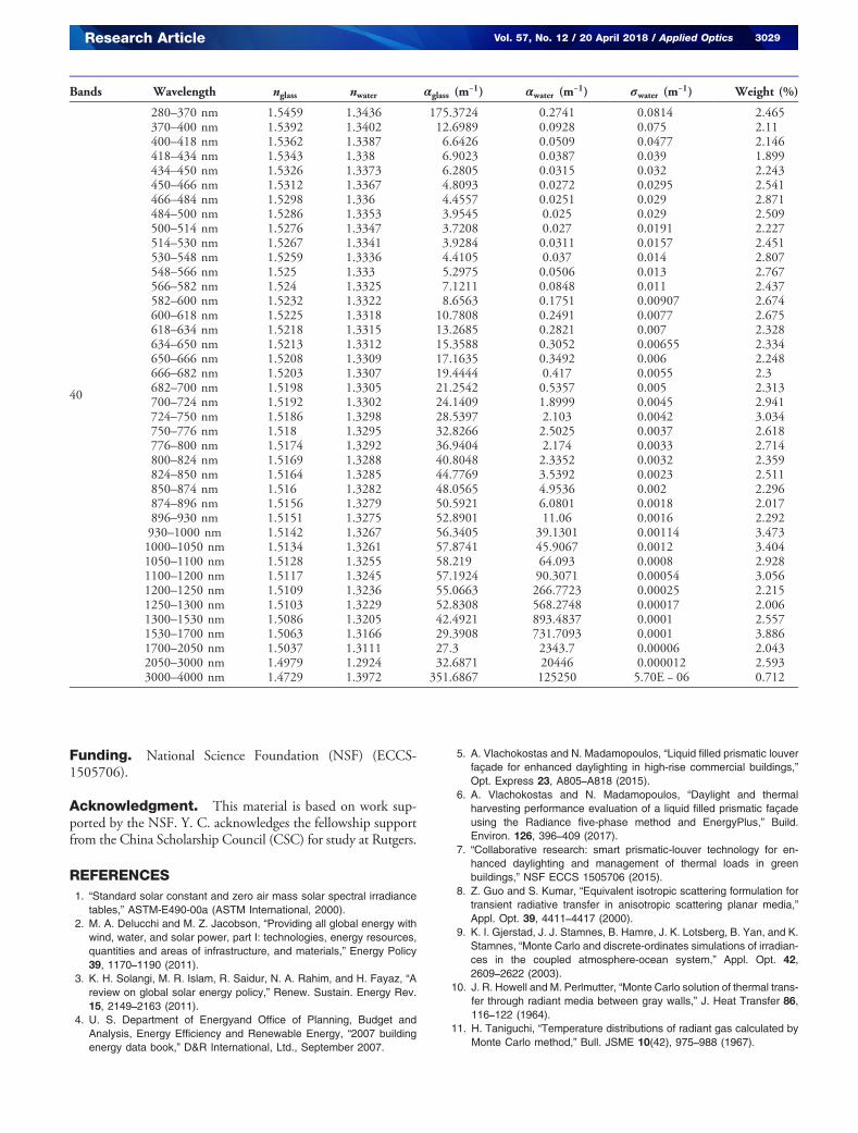
The solar spectrum was divided into many discrete bands,and band-averaged spectral properties are used in the presentstudy. We divided the spectrum in a way such that propertyprofiles are relatively smooth within each band. Another factorconsidered was that each band contains a close amount of solarenergy so that the spectral-weighting factor is not too diverse.In the region with condensed energy, such as the VIS and NIRregimes, the bandwidth is relatively narrow, while in the IRregion, the bandwidth is generally wide. In this study, we com-pared the results calculated from 1 full band (gray), 3, 7, 20,and 40 bands, respectively. The data for band divisions andassociated properties are shown in Table 2 in Appendix A.
3. RESULTS AND DISCUSSION
First, we examine the MC calculations for solar collimated ir-radiation under different photon numbers, band numbers, andelement numbers. Four sets of photon numbers for each spec-tral band were considered, that is, 106, 107, 108, and 109 pho-ton bundles, respectively. The 2D cross-sectional louver wasalso meshed with four different element sets, that is, 1086,4032, 7140, and 11,130 elements, respectively. A brief illustra-tion of element division is shown in Fig. 1(b).
In all the present calculations, a laptop equipped with anIntel Core i-7-4720HQ 2.60 GHz CPU was used. The specificCPU times used for different cases of various photon numbers,element numbers, and band numbers are listed in Table 1. It isshown that with an increasing photon number, the CPU timeincreases. The relation between the photons number and theCPU time is basically linear. The element number does notaffect the CPU time too much in this study as the presentMC model needs only to trace the incident solar irradiationand record the final position for each absorbed photon. The
3024 Vol. 57, No. 12 / 20 April 2018 / Applied Optics Research Article
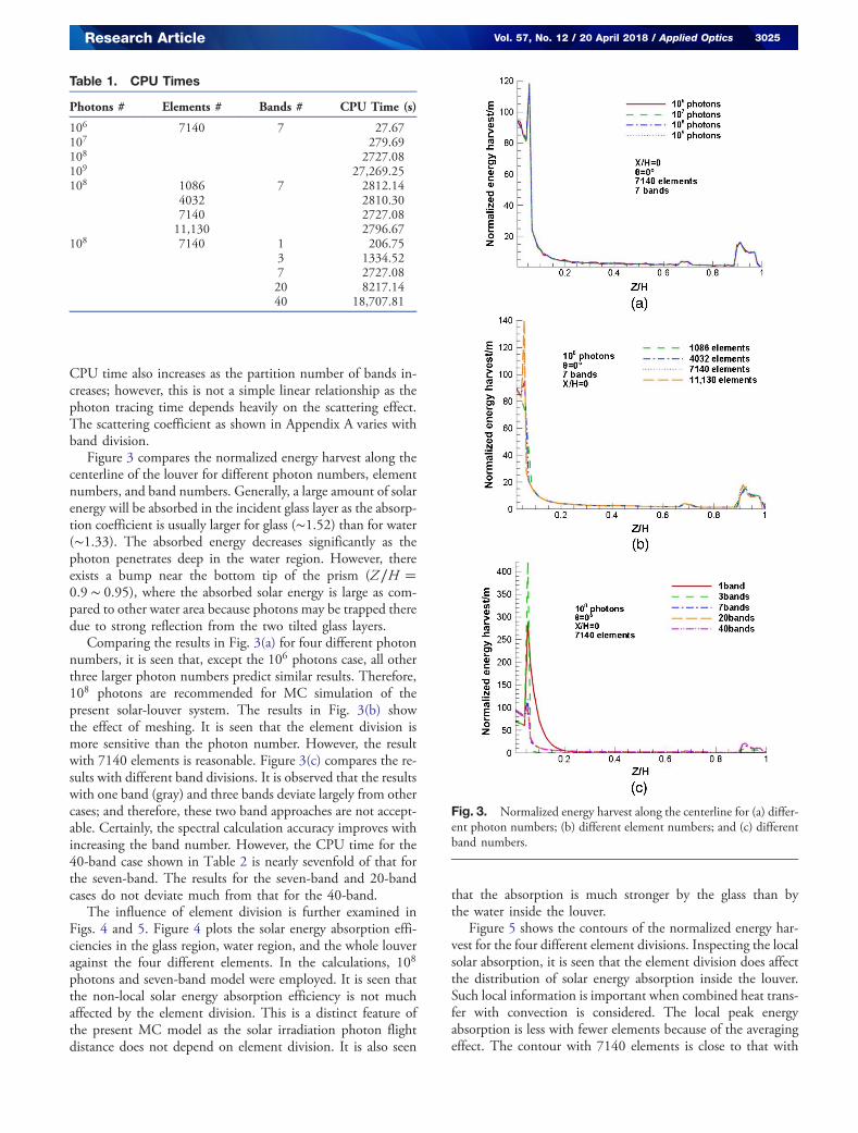
CPU time also increases as the partition number of bands in-creases; however, this is not a simple linear relationship as thephoton tracing time depends heavily on the scattering effect.The scattering coefficient as shown in Appendix A varies withband division.
Figure 3 compares the normalized energy harvest along thecenterline of the louver for different photon numbers, elementnumbers, and band numbers. Generally, a large amount of solarenergy will be absorbed in the incident glass layer as the absorp-tion coefficient is usually larger for glass (∼1.52) than for water(∼1.33). The absorbed energy decreases significantly as thephoton penetrates deep in the water region. However, thereexists a bump near the bottom tip of the prism (Z∕H �0.9 ∼ 0.95), where the absorbed solar energy is large as com-pared to other water area because photons may be trapped theredue to strong reflection from the two tilted glass layers.
Comparing the results in Fig. 3(a) for four different photonnumbers, it is seen that, except the 106 photons case, all otherthree larger photon numbers predict similar results. Therefore,108 photons are recommended for MC simulation of thepresent solar-louver system. The results in Fig. 3(b) showthe effect of meshing. It is seen that the element division ismore sensitive than the photon number. However, the resultwith 7140 elements is reasonable. Figure 3(c) compares the re-sults with different band divisions. It is observed that the resultswith one band (gray) and three bands deviate largely from othercases; and therefore, these two band approaches are not accept-able. Certainly, the spectral calculation accuracy improves withincreasing the band number. However, the CPU time for the40-band case shown in Table 2 is nearly sevenfold of that forthe seven-band. The results for the seven-band and 20-bandcases do not deviate much from that for the 40-band.
The influence of element division is further examined inFigs. 4 and 5. Figure 4 plots the solar energy absorption effi-ciencies in the glass region, water region, and the whole louveragainst the four different elements. In the calculations, 108
photons and seven-band model were employed. It is seen thatthe non-local solar energy absorption efficiency is not muchaffected by the element division. This is a distinct feature ofthe present MC model as the solar irradiation photon flightdistance does not depend on element division. It is also seen
that the absorption is much stronger by the glass than bythe water inside the louver.
Figure 5 shows the contours of the normalized energy har-vest for the four different element divisions. Inspecting the localsolar absorption, it is seen that the element division does affectthe distribution of solar energy absorption inside the louver.Such local information is important when combined heat trans-fer with convection is considered. The local peak energyabsorption is less with fewer elements because of the averagingeffect. The contour with 7140 elements is close to that with
Table 1. CPU Times
Photons # Elements # Bands # CPU Time (s)
106 7140 7 27.67107 279.69108 2727.08109 27,269.25108 1086 7 2812.14
4032 2810.307140 2727.0811,130 2796.67
108 7140 1 206.753 1334.527 2727.0820 8217.1440 18,707.81
Fig. 3. Normalized energy harvest along the centerline for (a) differ-ent photon numbers; (b) different element numbers; and (c) differentband numbers.
Research Article Vol. 57, No. 12 / 20 April 2018 / Applied Optics 3025

11,130 elements, with a variation generally under 5%.Compromising the computation efficiency and accuracy, themeshing model with 7140 elements is adopted in the calcula-tions thereafter.
Band partition is a very important issue for accurate andefficient modeling of solar irradiation. Figure 6 shows thetotal/glass/water solar energy absorption efficiencies under
normal solar incidence for different band partitions. It is seenthat the absorption efficiency generally decreases with an in-creasing band number, except the cases from one band to threebands for glass. However, the variation from seven bands to 40bands is very small. For example, the total efficiency is 63.2%for the seven-band model and 61.2% for the 40-band model,and only 3.27% difference between the two cases.
Figure 7 shows the contours of normalized energy harvest inthe whole louver for different band division approaches. Itshows that the one-band model has a large absorption in theglass, that is, the solar irradiation is heavily attenuated by theincident glass layer. The three-band model has a deeper solarpenetration. The results in Figs. 6 and 7 indicate that the one-band and three-band models are not suitable for solar irradia-tion in the glass–water system. The seven-band model would bea good choice as its result is close to the 20-, and 40-band mod-els, while its CPU time is the least. Therefore, the seven-bandmodel will be adopted for calculations thereafter. The seven-band model includes one band for the UV light, two bandsfor the VIS light, and four bands for IR light, as specifiedin Table 1.
Now, the effect of solar incidence angle is investigated, uti-lizing seven bands, 108 photons, and 7140 elements. To sim-plify the problem, the circumferential angle is fixed at zero,while the azimuthal angle varies from 0° (normal) to 90°.Figure 8 compares the contours of normalized energy harvest
Fig. 4. Solar energy absorption efficiency versus elements division.
Fig. 5. Contours of the normalized energy harvest (/m) for differentelement divisions.
Fig. 6. Solar energy absorption efficiency versus band division.
Fig. 7. Contours of normalized energy harvest (/m) with differentband partitions.
Fig. 8. Normalized energy harvest (/m) for different incidentangles.
3026 Vol. 57, No. 12 / 20 April 2018 / Applied Optics Research Article

for six different incident angles. It is seen that the normalizedenergy harvest decreases as the incident angle enlarges. This isbecause the radiation penetration in the louver is shorter for alarge incident angle. With an increasing angle, the solar heatflux irradiated on the louver surface decreases under constantsolar constant on the earth’s surface. This further reduces theharvested solar energy in the louver.
Figure 9 depicts the total/glass/water absorption efficienciesvs. the sunlight incident angle. It is seen that the variation ofabsorption efficiency in the water is smoother than that in theglass. This is because the glass medium is the first layer the sun-light passes and harvests nearly twice the solar energy than thewater. Clearly the total energy absorption efficiency reduceswhen the solar incidence angle increases. There exist two ob-vious drops; one occurred from 15° to 20°, another one oc-curred around 75°. The first drop is due to the reduction ofeffective glass area with an increasing incident angle. The sec-ond drop is because of the increased reflectivity in the firstglass–water interface. With normal incidence (0°), the absorp-tion efficiency is the largest, reaching 63.2%. At the angle of15°, the total absorption efficiency only slightly reduces to62.1%, only 1.7% reduction as compared to the normal inci-dence. At 20°, the efficiency drops to 55.5%. At 75°, the totalabsorption efficiency further drops to 36.0%.
Finally, it would be meaningful to understand the absorp-tion of solar energy under some distinct solar spectral ranges.Those that are not absorbed will be either transmitted into theroom space or reflected outside the window. Here we considerthree distinct spectra, that is, UV in the range 280–400 nm,VIS in the range 400–700 nm, and IR in the range 700–4000 nm. To differentiate the three spectra, the seven-bandmodel is adopted in the calculations. Figure 10 shows that allangles have the same absorption tendency. The glass mediumabsorbs the most UV and VIS light. The water medium absorbslittle UV and VIS light. As for the IR, both the glass and waterabsorb strongly. The absorption of the IR solar energy in thelouver is very high, about 85.9% for the 0° case, 84.5% for the15° case, 73.7% for the 30° case, 68.8% for the 45° case, 65.5%
for the 60° case, and 53.3% for the 75° case. Since more than50% of solar radiation consists of IR radiation, the water insidethe hollow louver is significant for solar energy harvesting, par-ticularly in the 30° and 45° cases. For UV light, all angle casesabsorb the majority of UV light, and the total absorptionreaches 84.9% for the 0° case, 85.4% for the 15° case, 73.4%for the 30° case, 66.0% for the 45° case, 63.6% for the 60° case,and 51.8% for the 75° case, respectively. It means that UV lightis well absorbed by the louver, protecting occupants from over-exposure to UV light. With the angle increasing, the absorptionefficiency for VIS light drops down. The absorption of VIS inthe louver is weak, only about 34.9% for the 0° case, 32.1% forthe 15° case, 17.1% for the 30° case, 13.4% for the 45° case,13.0% for the 60° case, and 10.5% for the 75° case. Therefore,most of VIS light can transmit through the louver for naturalillumination.
4. CONCLUSIONS
The collimated solar irradiation into a silica glass louver filledwith water is investigated using the Monte Carlo ray tracingmethod. The AM 1.5 solar irradiation spectrum and spectralproperties of materials are considered. The influences of grid
Fig. 9. Effect of incident angle on solar energy absorptionefficiency.
Fig. 10. Solar energy absorption efficiencies in three distinctspectra with an incident polar angle of 0°, 15°, 30°, 45°, 60°, and75°, respectively.
Research Article Vol. 57, No. 12 / 20 April 2018 / Applied Optics 3027

meshing, spectral band division, photon number, and solar in-cident angle are examined. The absorption efficiency againstdifferent light regimes of UV, VIS, and IR, as well as betweenthe glass and water is distinguished. Some concluding remarkscan be drafted as follows.
The total solar energy absorption efficiency in the louveris 61.2% under normal incidence based on the 40-bandcalculation. The seven-band model gives a lightly highervalue at 63.2%, but it reduces the CPU time to less than15% of that by the 40-band model. The one-band (gray) modeland three-band (splitting UV, VIS, and IR) model are not suit-able for modeling the solar energy transport in glass–waterstructures.
The solar energy absorption efficiency decreases as the in-cident polar angle increases. From normal incidence to 15°,however, the absorption efficiency is just reduced by 1.7%.
As the polar angle increases to 20°, the efficiency drops to55.5%. At 75°, the total absorption efficiency drops to 36.0%.
Both the glass and water in the louver absorb IR strongly.The glass absorbs the most UV and VIS light, and the waterabsorbs little UV and VIS light. Under normal incidence, about85% IR and UV solar energy is absorbed by the louver. Theabsorption of VIS in the louver is weak, about 34.9% for nor-mal incidence, and it drops to 10.5% for the 75° case.
The calculation of overall solar energy harvest in the louveris a weak function of element division. However, the local en-ergy absorption does depend on the element division. A finermesh will give a better symmetric distribution in the louver. Forcollimated irradiation, computational accuracy is also a weakfunction of photon number. With 108 photons for each spec-tral band, a good compromise between computational efficacyand accuracy can be realized.
APPENDIX A
Table 2. Spectral Properties of Materials for Various Bands
Bands Wavelength nglass nwater αglass (m−1) αwater (m−1) σwater (m−1) Weight (%)
1 280–4000 nm 1.5216 1.3307 35.0864 381.3735 0.000165 100
3280–400 nm 1.5429 1.3421 102.5293 0.009 0.1929 4.575400–700 nm 1.5261 1.3338 3.734 0.06265 0.0074 43.77700–4000 nm 1.5122 1.3247 47.735 2994.58 0.0016 51.655
7
280–400 nm 1.5429 1.3421 102.5293 0.1929 0.009 4.575400–548 nm 1.53 1.336 4.92 0.0276 0.032 21.288548–700 nm 1.522 1.3316 12.823 0.008 0.2641 21.643700–850 nm 1.5178 1.3294 34.1597 2.4007 0.0026 16.195850–1100 nm 1.5143 1.3268 54.6798 32.3981 0.0013 16.6731100–1530 nm 1.5104 1.323 52.0098 435.3489 0.000165 10.0881530–4000 nm 1.501 1.3148 54.7049 16225.8 0.000006 9.538
20
280–400 nm 1.5429 1.3421 102.5293 0.1929 0.009 4.575400–450 nm 1.5343 1.338 6.5916 0.0403 0.0503 6.149450–500 nm 1.5299 1.336 4.4101 0.0258 0.0294 7.776500–530 nm 1.5271 1.3344 3.8295 0.0292 0.0156 4.559530–566 nm 1.5253 1.3332 5.049 0.0468 0.014 5.509566–600 nm 1.5236 1.3323 7.9275 0.1323 0.009 5.021600–650 nm 1.5219 1.3315 12.9215 0.276 0.0077 7.199650–700 nm 1.5203 1.3307 19.3064 0.4348 0.0048 6.72700–750 nm 1.5189 1.33 26.3851 2.0035 0.00368 6.001750–800 nm 1.5177 1.3293 34.9274 2.3347 0.00323 5.316800–850 nm 1.5167 1.3287 42.8651 2.9598 0.002497 4.878850–930 nm 1.5156 1.3278 50.5189 7.4352 0.00175 6.651930–1000 nm 1.5142 1.3267 56.3405 39.1301 0.00114 3.5561000–1100 nm 1.5131 1.3258 58.0337 54.3222 0.001 6.4651100–1200 nm 1.5117 1.3245 57.1924 90.3071 0.000544 3.1521200–1300 nm 1.5106 1.3233 54.0033 410.1431 0.000165 4.3051300–1530 nm 1.5086 1.3205 42.4921 893.4837 0.0001 2.6311530–1700 nm 1.5063 1.3166 29.3908 731.7093 0.0001 4.0171700–3000 nm 1.5004 1.3005 30.3508 12595 1.43E − 05 4.783000–4000 nm 1.4729 1.3972 351.6867 125250 5.74E − 06 0.74
(Table continued)
3028 Vol. 57, No. 12 / 20 April 2018 / Applied Optics Research Article
Funding. National Science Foundation (NSF) (ECCS-1505706).
Acknowledgment. This material is based on work sup-ported by the NSF. Y. C. acknowledges the fellowship supportfrom the China Scholarship Council (CSC) for study at Rutgers.
REFERENCES1. “Standard solar constant and zero air mass solar spectral irradiance
tables,” ASTM-E490-00a (ASTM International, 2000).2. M. A. Delucchi and M. Z. Jacobson, “Providing all global energy with
wind, water, and solar power, part I: technologies, energy resources,quantities and areas of infrastructure, and materials,” Energy Policy39, 1170–1190 (2011).
3. K. H. Solangi, M. R. Islam, R. Saidur, N. A. Rahim, and H. Fayaz, “Areview on global solar energy policy,” Renew. Sustain. Energy Rev.15, 2149–2163 (2011).
4. U. S. Department of Energyand Office of Planning, Budget andAnalysis, Energy Efficiency and Renewable Energy, “2007 buildingenergy data book,” D&R International, Ltd., September 2007.
5. A. Vlachokostas and N. Madamopoulos, “Liquid filled prismatic louverfaçade for enhanced daylighting in high-rise commercial buildings,”Opt. Express 23, A805–A818 (2015).
6. A. Vlachokostas and N. Madamopoulos, “Daylight and thermalharvesting performance evaluation of a liquid filled prismatic façadeusing the Radiance five-phase method and EnergyPlus,” Build.Environ. 126, 396–409 (2017).
7. “Collaborative research: smart prismatic-louver technology for en-hanced daylighting and management of thermal loads in greenbuildings,” NSF ECCS 1505706 (2015).
8. Z. Guo and S. Kumar, “Equivalent isotropic scattering formulation fortransient radiative transfer in anisotropic scattering planar media,”Appl. Opt. 39, 4411–4417 (2000).
9. K. I. Gjerstad, J. J. Stamnes, B. Hamre, J. K. Lotsberg, B. Yan, and K.Stamnes, “Monte Carlo and discrete-ordinates simulations of irradian-ces in the coupled atmosphere-ocean system,” Appl. Opt. 42,2609–2622 (2003).
10. J. R. Howell and M. Perlmutter, “Monte Carlo solution of thermal trans-fer through radiant media between gray walls,” J. Heat Transfer 86,116–122 (1964).
11. H. Taniguchi, “Temperature distributions of radiant gas calculated byMonte Carlo method,” Bull. JSME 10(42), 975–988 (1967).
Bands Wavelength nglass nwater αglass (m−1) αwater (m−1) σwater (m−1) Weight (%)
40
280–370 nm 1.5459 1.3436 175.3724 0.2741 0.0814 2.465370–400 nm 1.5392 1.3402 12.6989 0.0928 0.075 2.11400–418 nm 1.5362 1.3387 6.6426 0.0509 0.0477 2.146418–434 nm 1.5343 1.338 6.9023 0.0387 0.039 1.899434–450 nm 1.5326 1.3373 6.2805 0.0315 0.032 2.243450–466 nm 1.5312 1.3367 4.8093 0.0272 0.0295 2.541466–484 nm 1.5298 1.336 4.4557 0.0251 0.029 2.871484–500 nm 1.5286 1.3353 3.9545 0.025 0.029 2.509500–514 nm 1.5276 1.3347 3.7208 0.027 0.0191 2.227514–530 nm 1.5267 1.3341 3.9284 0.0311 0.0157 2.451530–548 nm 1.5259 1.3336 4.4105 0.037 0.014 2.807548–566 nm 1.525 1.333 5.2975 0.0506 0.013 2.767566–582 nm 1.524 1.3325 7.1211 0.0848 0.011 2.437582–600 nm 1.5232 1.3322 8.6563 0.1751 0.00907 2.674600–618 nm 1.5225 1.3318 10.7808 0.2491 0.0077 2.675618–634 nm 1.5218 1.3315 13.2685 0.2821 0.007 2.328634–650 nm 1.5213 1.3312 15.3588 0.3052 0.00655 2.334650–666 nm 1.5208 1.3309 17.1635 0.3492 0.006 2.248666–682 nm 1.5203 1.3307 19.4444 0.417 0.0055 2.3682–700 nm 1.5198 1.3305 21.2542 0.5357 0.005 2.313700–724 nm 1.5192 1.3302 24.1409 1.8999 0.0045 2.941724–750 nm 1.5186 1.3298 28.5397 2.103 0.0042 3.034750–776 nm 1.518 1.3295 32.8266 2.5025 0.0037 2.618776–800 nm 1.5174 1.3292 36.9404 2.174 0.0033 2.714800–824 nm 1.5169 1.3288 40.8048 2.3352 0.0032 2.359824–850 nm 1.5164 1.3285 44.7769 3.5392 0.0023 2.511850–874 nm 1.516 1.3282 48.0565 4.9536 0.002 2.296874–896 nm 1.5156 1.3279 50.5921 6.0801 0.0018 2.017896–930 nm 1.5151 1.3275 52.8901 11.06 0.0016 2.292930–1000 nm 1.5142 1.3267 56.3405 39.1301 0.00114 3.4731000–1050 nm 1.5134 1.3261 57.8741 45.9067 0.0012 3.4041050–1100 nm 1.5128 1.3255 58.219 64.093 0.0008 2.9281100–1200 nm 1.5117 1.3245 57.1924 90.3071 0.00054 3.0561200–1250 nm 1.5109 1.3236 55.0663 266.7723 0.00025 2.2151250–1300 nm 1.5103 1.3229 52.8308 568.2748 0.00017 2.0061300–1530 nm 1.5086 1.3205 42.4921 893.4837 0.0001 2.5571530–1700 nm 1.5063 1.3166 29.3908 731.7093 0.0001 3.8861700–2050 nm 1.5037 1.3111 27.3 2343.7 0.00006 2.0432050–3000 nm 1.4979 1.2924 32.6871 20446 0.000012 2.5933000–4000 nm 1.4729 1.3972 351.6867 125250 5.70E − 06 0.712
Research Article Vol. 57, No. 12 / 20 April 2018 / Applied Optics 3029

12. W. J. Yang, H. Taniguchi, and K. Kudo, “Radiative heat transfer by theMonte Carlo method,” Adv. Heat Transfer 27, 1–17 (1995).
13. J. R. Howell, “The Monte Carlo method in radiative heat transfer,”J. Heat Transfer 120, 547–560 (1998).
14. D. A. Kaminski, “Radiative transfer from a gray, absorbing-emitting,isothermal medium in a conical enclosure,” J. Sol. Energy Eng.111, 324–329 (1989).
15. Z. Guo, S. Kumar, and K. C. San, “Multidimensional Monte Carlosimulation of short-pulse laser transport in scattering media,” J.Thermophys. Heat Transf. 14, 504–511 (2000).
16. H. Iwabuchi, “Efficient Monte Carlo methods for radiative transfermodeling,” J. Atmos. Sci. 63, 2324–2339 (2006).
17. “Standard tables for reference solar spectral irradiances: direct normaland hemispherical on 37° tilted surface,” ASTM G173-03 (ASTMInternational, 2003).
18. D. V. Hoyt, “A model for the calculation of solar global isolation,” Sol.Energy 21, 27–35 (1978).
19. C. Gueymard, “A two-band model for the calculation of clear sky solarirradiance, illuminance, and photosynthetically active radiation at theearth’s surface,” Sol. Energy 43, 253–265 (1989).
20. J. F. Escobedo, E. N. Gomes, A. P. Oliveira, and J. Soares, “Modelinghourly and daily fractions of UV, PAR and NIR to global solar radiationunder various sky conditions at Botucatu, Brazil,” Appl. Energy 86,299–309 (2009).
21. R. E. Bird and C. Riordan, “Simple solar spectral model for directand diffuse irradiance on horizontal and tilted planes at the earth’s
surface for cloudless atmospheres,” J. Clim. Appl. Meteorol. 25,87–97 (1986).
22. M. Lave and K. Jan, “Optimum fixed orientations and benefits oftracking for capturing solar radiation in the continental UnitedStates,” Renew. Energy 36, 1145–1152 (2011).
23. R. Yan, T. K. Saha, P. Meredith, and S. Goodwin, “Analysisof yearlong performance of differently tilted photovoltaic systemsin Brisbane,” Energy Convers. Manage. 74, 102–108 (2013).
24. I. H. Rowlands, B. P. Kemery, and I. Beausoleil-Morrison, “Optimalsolar-PV tilt angle and azimuth: an Ontario (Canada) case-study,”Energy Policy 39, 1397–1409 (2011).
25. E. Papanicolaou, K. Voropoulos, and V. Belessiotis, “Natural convec-tive heat transfer in an asymmetric greenhouse-type solar still-effect ofangle of inclination,” Numer. Heat Transfer, Part A 42, 855–880(2002).
26. R. Tang and T. Wu, “Optimal tilt-angles for solar collectors used inChina,” Appl. Energy 79, 239–248 (2004).
27. B. Hunter and Z. Guo, “Phase-function normalization for accurateanalysis of ultrafast collimated radiative transfer,” Appl. Opt. 51,2192–2201 (2012).
28. M. Herzberger, “The dispersion of optical glass,” J. Opt. Soc. Am. 32,70–77 (1942).
29. M. Rubin, “Optical properties of soda lime silica glasses,” Sol. Eng.Mater. 12, 275–288 (1985).
30. G. M. Hale and M. R. Querry, “Optical constants of water in the200-nm to 200-μmwavelength region,” Appl. Opt. 12, 555–563 (1973).
3030 Vol. 57, No. 12 / 20 April 2018 / Applied Optics Research Article