spectral m800 mkii - clubsound.info · r 240 245 250 251 255 color macro & white 0 g 0 0 255...
TRANSCRIPT

Spectral M800 MKII
USER MANUAL
43530-43531-43532
1
245mm2
05
mm
245mm
30mm
13mm
30mm
12
3
45
67
89
10
1112
13 14 15
16
17
181920
18
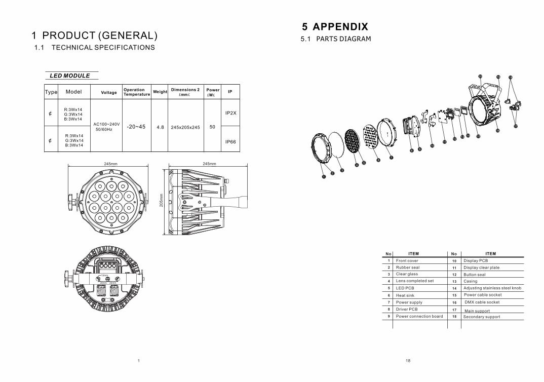
1.1 TECHNICAL SPECIFICATIONS
LED MODULE
1 PRODUCT (GENERAL)
Model VoltageOperation Temperature
Weight Dimensions 2 £mm£
Power
£W£IP
AC100~240V
50/60Hz-20~45 4.8 245x205x245
IP66
50
Type
¢
¢
R:3Wx14 G:3Wx14 B:3Wx14
R:3Wx14 G:3Wx14 B:3Wx14
5 APPENDIX5.1 PARTS DIAGRAM
1
2
3
4
5
6
7
8
9
10Front cover
Rubber seal
Clear glass
Lens completed set
LED PCB
Heat sink
Power supply
Power connection board
Display PCB
Driver PCB
Casing
Adjusting stainless steel knob
No ITEM
Display clear plate
Button seal
11
12
13
14
15
16
17
18
No ITEM
Main support
Secondary support
Power cable socket
DMX cable socket
IP2X
217
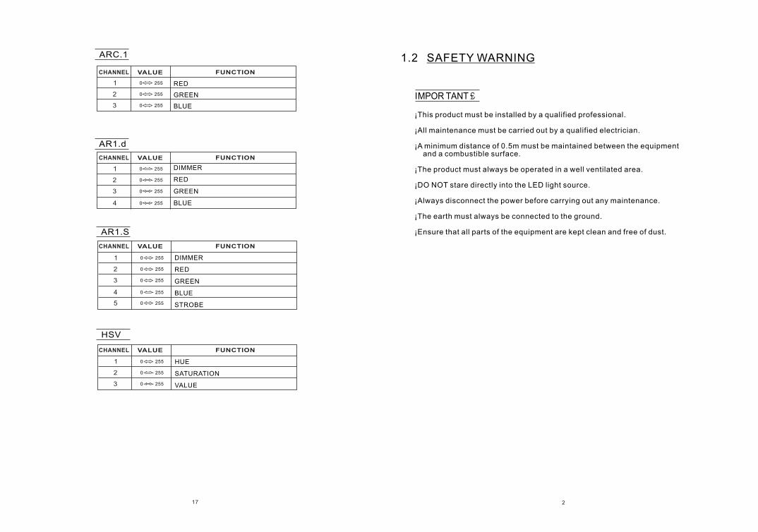
RED
GREEN
BLUE
0 2551
0
0
255
255
2
3
0 2551
0
0
255
255
2
3
DIMMER
RED
GREEN
BLUE0 2554
ARC.1
AR1.d
0
0
255
255
1
1
0
0
0
0
255
255
255
255
2
2
3
3
0 2554
DIMMER
RED
GREEN
BLUE
STROBE0 2555
HUE
SATURATION
VALUE
AR1.S
HSV
1.2 SAFETY WARNING
IMPOR TANT £
¡This product must be installed by a qualified professional.
¡All maintenance must be carried out by a qualified electrician.
¡A minimum distance of 0.5m must be maintained between the equipment and a combustible surface.
¡The product must always be operated in a well ventilated area.
¡DO NOT stare directly into the LED light source.
¡Always disconnect the power before carrying out any maintenance.
¡The earth must always be connected to the ground.
¡Ensure that all parts of the equipment are kept clean and free of dust.
CHANNEL VALUE FUNCTION
CHANNEL VALUE FUNCTION
CHANNEL VALUE FUNCTION
CHANNEL VALUE FUNCTION
3
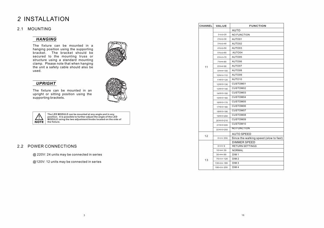
11
NO FUNCTION
AUTO01
AUTO02
AUTO03
AUTO04
AUTO05
AUTO06
AUTO07
AUTO08
AUTO09
AUTO10
CUSTOM01
CUSTOM02
CUSTOM03
CUSTOM04
CUSTOM05
CUSTOM06
CUSTOM07
CUSTOM08
CUSTOM09
CUSTOM10
NO FUNCTION
AUTO
DIMMER SPEED 0 9
10
30
70
130
190
29
69
129
189
255
13
AUTO SPEED
0 25512
121 130
131 140
141 150
151 160
161 170
171 180
181 190
191 200
201 210
211 220
221 255
71 80
81 90
91 100
101 110
111 120
0 20
21 30
31 40
41 50
51 60
61 70
16
2.1 MOUNTING
HANGING
UPRIGHT
The fixture can be mounted in an upright or sitting position using the supporting brackets.
The fixture can be mounted in a hanging position using the supporting bracket. The bracket should be secured to the mounting truss or structure using a standard mounting clamp. Please note that when hanging the unit a safety cable should also be used.
@ 220V: 24 units may be connected in series
@120V: 12 units may be connected in series
The LED MODULE can be mounted at any angle and in any position. It is possible to further adjust the angle of the LED MODULE using the two adjustment knobs located on the side of the fixture.
2.2 POWER CONNECTIONS
2 INSTALLATION
RETURN SETTINGS
NORMAL
DIM 1
DIM 2
DIM 3
DIM 4
Since the walking speed (slow to fast)
CHANNEL VALUE FUNCTION
4
0 9
10
10
100
110
180
190
0
10
20
30
40
50
60
70
80
90
100
110
99
109
179
189
255
9
19
29
39
49
59
69
79
89
99
109
119
120 129
0
1
2
3
4
5
6
7
8
9
10
11
12
13
14
15
16
17
18
19
20
130
140
150
160
170
180
190
200
139
149
159
169
179
189
199
255
15
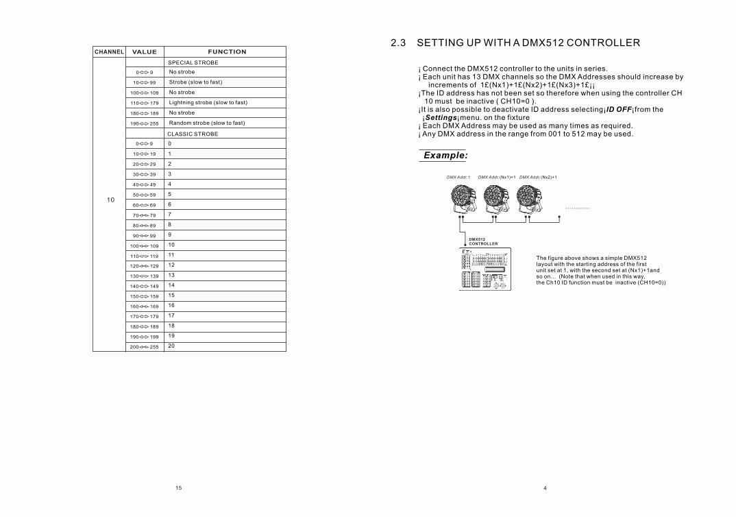
No strobe
Strobe (slow to fast)
No strobe
Lightning strobe (slow to fast)
No strobe
Random strobe (slow to fast)
SPECIAL STROBE
CLASSIC STROBE
CHANNEL VALUE FUNCTION
2.3 SETTING UP WITH A DMX512 CONTROLLER
The figure above shows a simple DMX512 layout with the starting address of the first unit set at 1, with the second set at (Nx1)+1and so on... (Note that when used in this way,the Ch10 ID function must be inactive (CH10=0))
DMX512CONTROLLER
¡ ¡ Each unit has 13 DMX channels so the DMX Addresses should increase by increments of 1£(Nx1)+1£(Nx2)+1£(Nx3)+1£¡¡¡The ID address has not been set so therefore when using the controller CH 10 must be inactive ( CH10=0 ).¡It is also possible to deactivate ID address selecting¡ID OFF¡from the ¡Settings¡menu. on the fixture ¡ Each DMX Address may be used as many times as required.¡ Any DMX address in the range from 001 to 512 may be used.
Connect the DMX512 controller to the units in series.
Example:
............
DMX Addr.1 DMX Addr.(Nx1)+1 DMX Addr.(Nx2)+1
5
TR16
0 2551
0
0
0
0
255
255
255
255
2
3
4
5
0 10
9
NO FUNCTION
RED 100% / GREEN UP / BLUE 0%
RED DOWN / GREEN 100% / BLUE 0%
RED 0% / GREEN 100% / BLUE UP
RED 0% / GREEN DOWN / BLUE 100%
RED UP / GREEN 0% / BLUE 100%
RED 100% /GREEN 0%/BLUE DOWN
RED 100%/GREEN UP/BLUE UP
RED DOWN/GREEN DOWN/BLUE 100%
RED 100%GREEN 100%/BLUE 100%WHITE 100%
WHITE1」3200K
WHITE2」3400K
WHITE3」4200K
WHITE4」4900K
WHITE5」5600K
WHITE6」5900K
WHITE7」6500K
WHITE8」7200K
WHITE9」8000K
WHITE10」8500K
WHITE11」10000K
11
31
51
71
91
111
131
151
171
201
206
211
216
221
226
231
236
241
246
30
50
70
90
110
130
150
170
200
205
210
215
220
225
230
235
240
245
250
251 255
COLOR MACRO & WHITE
0
0
0
255
255
255
6
7
8
MASTER DIMMER
MASTER DIMMER FINE
RED
RED FINE
GREEN
GREEN FINE
BLUE
BLUE FINE
£CH11 SELECT CUSTOM 01~10£CH3 CONTROL TIME£
£CH11 CUSTOM 01~10£CH4 FADE£ SELECT CONTROL
14
PR.01
PR.02
PR.10
RUN dMX
SLAV
SC.01
SC.02
SC.30
AT.01
AT.02
AT.10
AUTO
PR.01
PR.02
PR.10
d.(001~512)dMX
R.( 0~255)
G.( 0~255)
b. (0~255)
Sb. (0~20)
T.(0~255)
F.(0~255)
TR16
ARC.1
AR1.d
AR1.S
MENU R.(0~255)
G.(0~255)
b.(0~255)
ST.(0~20)
STAT
EDIT
HSV
OFF
RGBw
COLO
SET UPLd
REST
dIM1
dIM3
dIM2
dIM4dIM
UC
OFF
TOURPER S
CV1
CV3
CV2
OFFCURV
ON
OFFSLCK
CLAS
SPEC
STRB
BLAK
SAVEDERR
ENTER UP DOWNMENU
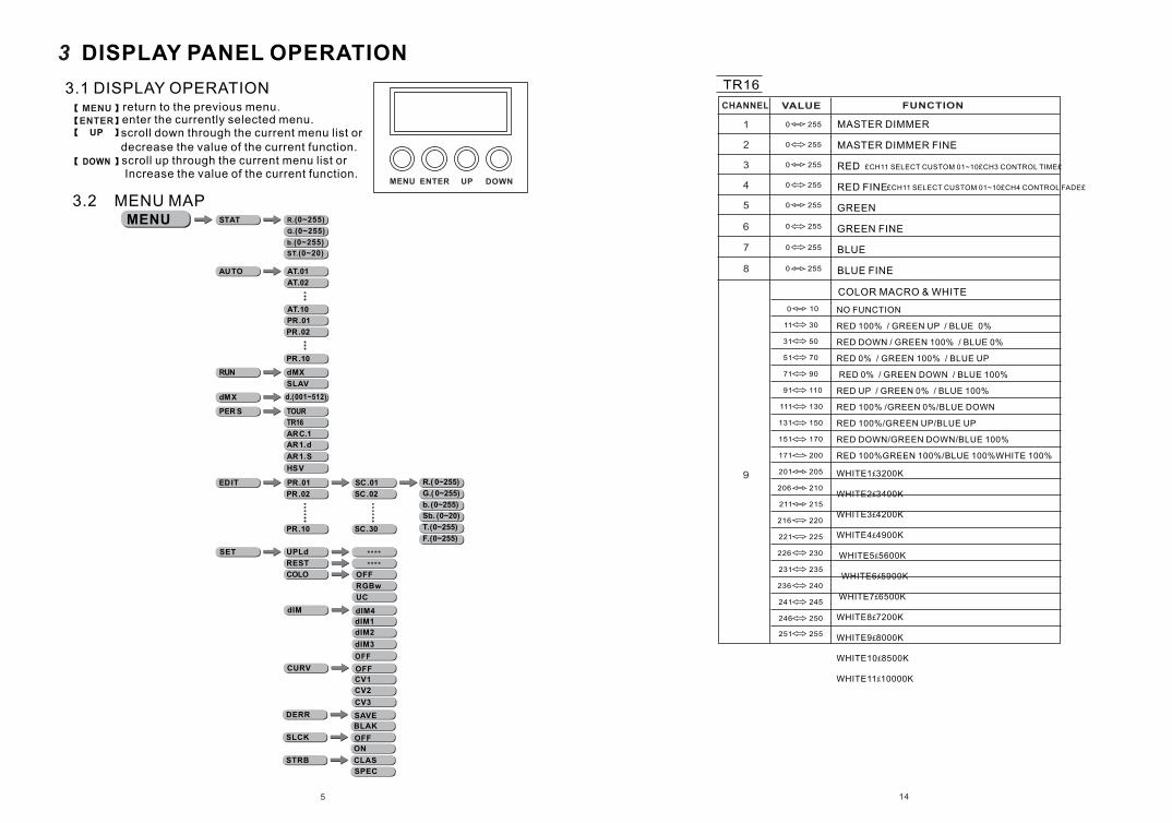
3.1 DISPLAY OPERATION
3 DISPLAY PANEL OPERATION
MENU
ENTER
return to the previous menu.enter the currently selected menu.scroll down through the current menu list or decrease the value of the current function.scroll up through the current menu list or Increase the value of the current function.
3.2 MENU MAP
CHANNEL VALUE FUNCTION
13
7
NO FUNCTION
AUTO01
AUTO02
AUTO03
AUTO04
AUTO05
AUTO06
AUTO07
AUTO08
AUTO09
AUTO10
CUSTOM01
CUSTOM02
CUSTOM03
CUSTOM04
CUSTOM05
CUSTOM06
CUSTOM07
CUSTOM08
CUSTOM09
CUSTOM10
NO FUNCTION
AUTO
RETURN SETTINGS
NORMAL
DIM 1
DIM 2
DIM 3
DIM 4
DIMMER SPEED 0 9
10
30
70
130
190
29
69
129
189
255
9
AUTO SPEED
0 2558
121 130
131 140
141 150
151 160
161 170
171 180
181 190
191 200
201 210
211 220
221 255
71 80
81 90
91 100
101 110
111 120
0 20
21 30
31 40
41 50
51 60
61 70
KEY ON
OFF
MENU STAT
AT.01
AT.02
AT.10
AUTO
PR.01
PR.02
PR.10
MENU
RUN dMX
SLAVMENU
6
R(0~255)
G(0~255)
b(0~255)
ST(0~20)
CAL wT.01CAL1****
wT.11
CALR **** OKCALR
RGBw R(0~255)
G(0~255)
b(0~255)
CAL2
R(0~255)
G(0~255)
b(0~255)
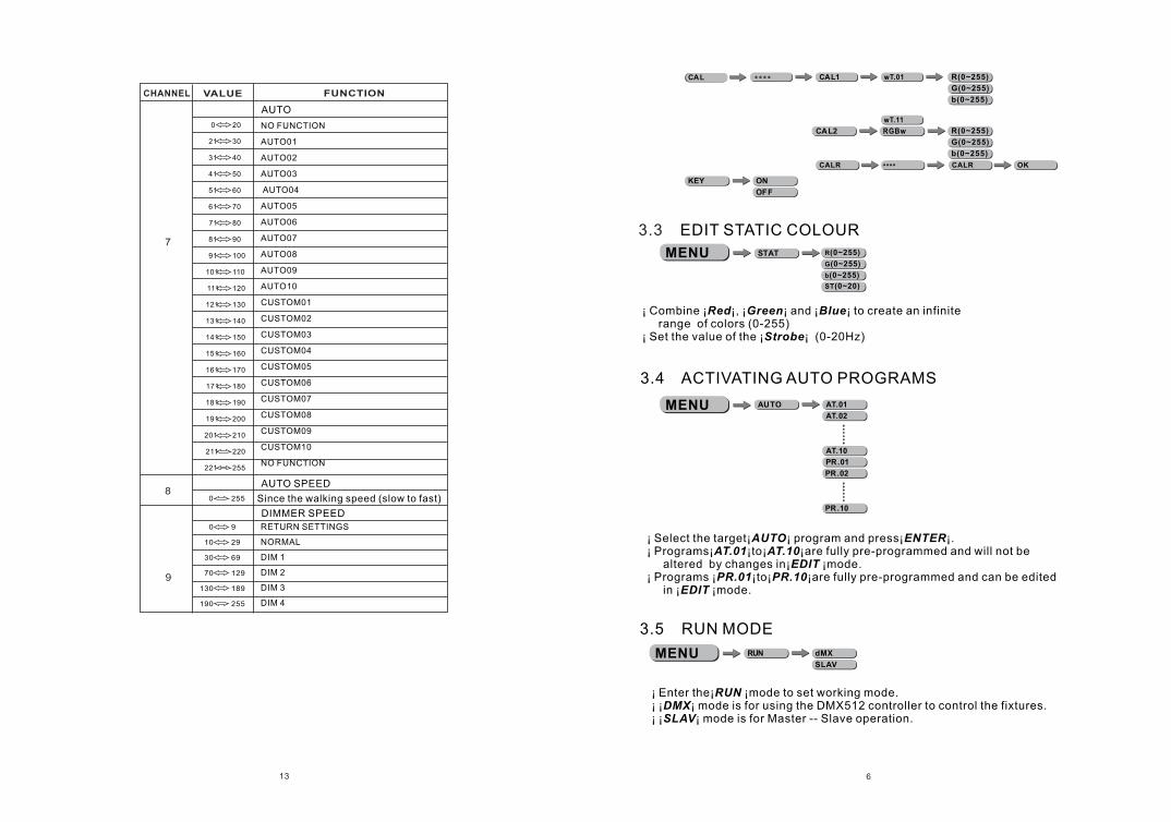
3.4 ACTIVATING AUTO PROGRAMS
¡ Select the target¡AUTO¡ program and press¡ENTER¡.¡ Programs¡AT.01¡to¡AT.10¡are fully pre-programmed and will not be altered by changes in¡EDIT ¡mode.¡ Programs ¡PR.01¡to¡PR.10¡are fully pre-programmed and can be edited in ¡EDIT ¡mode.
3.3 EDIT STATIC COLOUR
¡ Combine ¡Red¡, ¡Green¡ and ¡Blue¡ to create an infinite range of colors (0-255) ¡ Set the value of the ¡Strobe¡ (0-20Hz)
¡ Enter the¡RUN ¡mode to set working mode.¡ ¡DMX¡ mode is for using the DMX512 controller to control the fixtures.¡ ¡SLAV¡ mode is for Master -- Slave operation.
3.5 RUN MODE
Since the walking speed (slow to fast)
CHANNEL VALUE FUNCTION
12
0 9
6
10
100
110
180
190
0
10
20
30
40
50
60
70
80
90
100
110
99
109
179
189
255
9
19
29
39
49
59
69
79
89
99
109
119
120 129
0
1
2
3
4
5
6
7
8
9
10
11
12
13
14
15
16
17
18
19
20
130
140
150
160
170
180
190
200
139
149
159
169
179
189
199
255
d.(001~512)dMXMENU
PER SMENU
7
TR16
ARC.1
AR1.d
AR1.S
HSV
TOUR
MENU
PR.10 SC.30 T(0~255)
F(0~255)
PR.01
PR.02
SC.01
SC.02
R(0~2 55)
G(0~255 )
b(0~255)
Sb(0 ~20)
EDIT
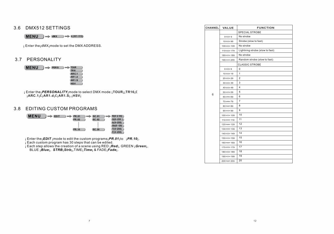
3.6 DMX512 SETTINGS
¡ Enter the¡dMX¡mode to set the DMX ADDRESS.
3.7 PERSONALITY
3.8 EDITING CUSTOM PROGRAMS
¡ Enter the¡EDIT ¡mode to edit the custom programs¡PR.01¡to ¡PR.10¡.¡ Each custom program has 30 steps that can be edited. ¡ Each step allows the creation of a scene using RED ¡Red¡, GREEN ¡Green¡, BLUE ¡Blue¡, STRB¡Strb¡,TIME¡Time¡ & FADE¡Fade¡.
¡ Enter the¡PERSONALITY¡mode to select DMX mode:¡ ¡¡ ¡£ ¡ ¡£¡ ¡£¡ ¡ ¡ ¡
TOUR TR16ARC.1 AR1.d AR1.S , HSV
CHANNEL VALUE FUNCTION
No strobe
Strobe (slow to fast)
No strobe
Lightning strobe (slow to fast)
No strobe
Random strobe (slow to fast)
SPECIAL STROBE
CLASSIC STROBE
OFF
RGBw
COLO
UPLd
REST
dIM1
dIM3
dIM2
dIM4dIM
UC
OFF
CV1
CV3
CV2
OFFCURV
ON
OFFSLCK
CLAS
SPEC
STRB
BLAK
SAVEDERR
SETMENU
811
£CH7 CUSTOM 01~10£CH2 TIME£ SELECT CONTROL
£CH7 CUSTOM 01~10£CH3 FADE£ SELECT CONTROL
0 2551 MASTER DIMMER
RED
GREEN
BLUE
0
0
0
255
255
255
2
3
4
0 10
5
NO FUNCTION
RED 100% / GREEN UP / BLUE 0%
RED DOWN / GREEN 100% / BLUE 0%
RED 0% / GREEN 100% / BLUE UP
RED 0% / GREEN DOWN / BLUE 100%
RED UP / GREEN 0% / BLUE 100%
RED 100% /GREEN 0%/BLUE DOWN
RED 100%/GREEN UP/BLUE UP
RED DOWN/GREEN DOWN/BLUE 100%
RED 100%GREEN 100%/BLUE 100%WHITE 100%
WHITE1£3200K
WHITE2£3400K
WHITE3£4200K
WHITE4£4900K
WHITE5£5600K
WHITE6£5900K
WHITE7£6500K
WHITE8£7200K
WHITE9£8000K
WHITE10£8500K
WHITE11£10000K
11
31
51
71
91
111
131
151
171
201
206
211
216
221
226
231
236
241
246
30
50
70
90
110
130
150
170
200
205
210
215
220
225
230
235
240
245
250
251 255
COLOR MACRO & WHITE
¡
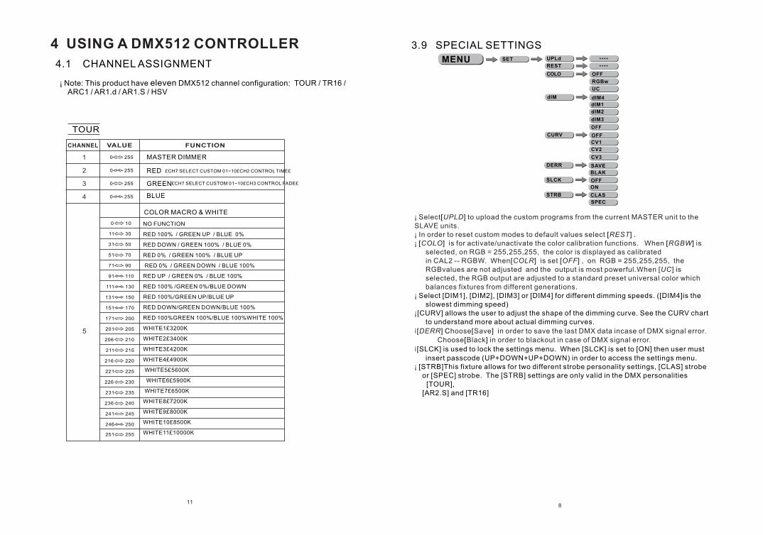
hoose Save in order to save the last DMX data incase of DMX signal error.
Choose Black in order to blackout in case of DMX signal error.
¡ Select UPLD to upload the custom programs from the current MASTER unit to the SLAVE units.¡ In order to reset custom modes to default values select REST .¡ COLO is for activate/unactivate the color calibration functions. When RGBW is
selected, on RGB = 255,255,255, the color is displayed as calibratedin CAL2 -- RGBW. When COLR is set OFF , on RGB = 255,255,255, the RGBvalues are not adjusted and the output is most powerful.When [UC] is selected, the RGB output are adjusted to a standard preset universal color which balances fixtures from different generations.
¡
¡ DERR
¡
¡
[ ]
[ ] [ ] [ ]
[ ] [ ]
Select [DIM1], [DIM2], [DIM3] or [DIM4] for different dimming speeds. ([DIM4]is the slowest dimming speed)
[CURV] allows the user to adjust the shape of the dimming curve. See the CURV chart to understand more about actual dimming curves.
[ ] C [ ]
[ ]
[SLCK] is used to lock the settings menu. When [SLCK] is set to [ON] then user must
insert passcode (UP+DOWN+UP+DOWN) in order to access the settings menu.[STRB]This fixture allows for two different strobe personality settings, [CLAS] strobe
or [SPEC] strobe. The [STRB] settings are only valid in the DMX personalities [TOUR],
[AR2.S] and [TR16]
3.9 SPECIAL SETTINGS
4.1 CHANNEL ASSIGNMENT
¡ Note: This product have eleven DMX512 channel configuration: TOUR / TR16 / ARC1 / AR1.d / AR1.S / HSV
4 USING A DMX512 CONTROLLER
TOUR
CHANNEL VALUE FUNCTION
109
MENU CAL wT.01CAL1****
wT.11
CALR **** OKCALR
RGBw R(0~255)
G(0~255)
b(0~255)
CAL2
R(0~255)
G(0~255)
b(0~255)
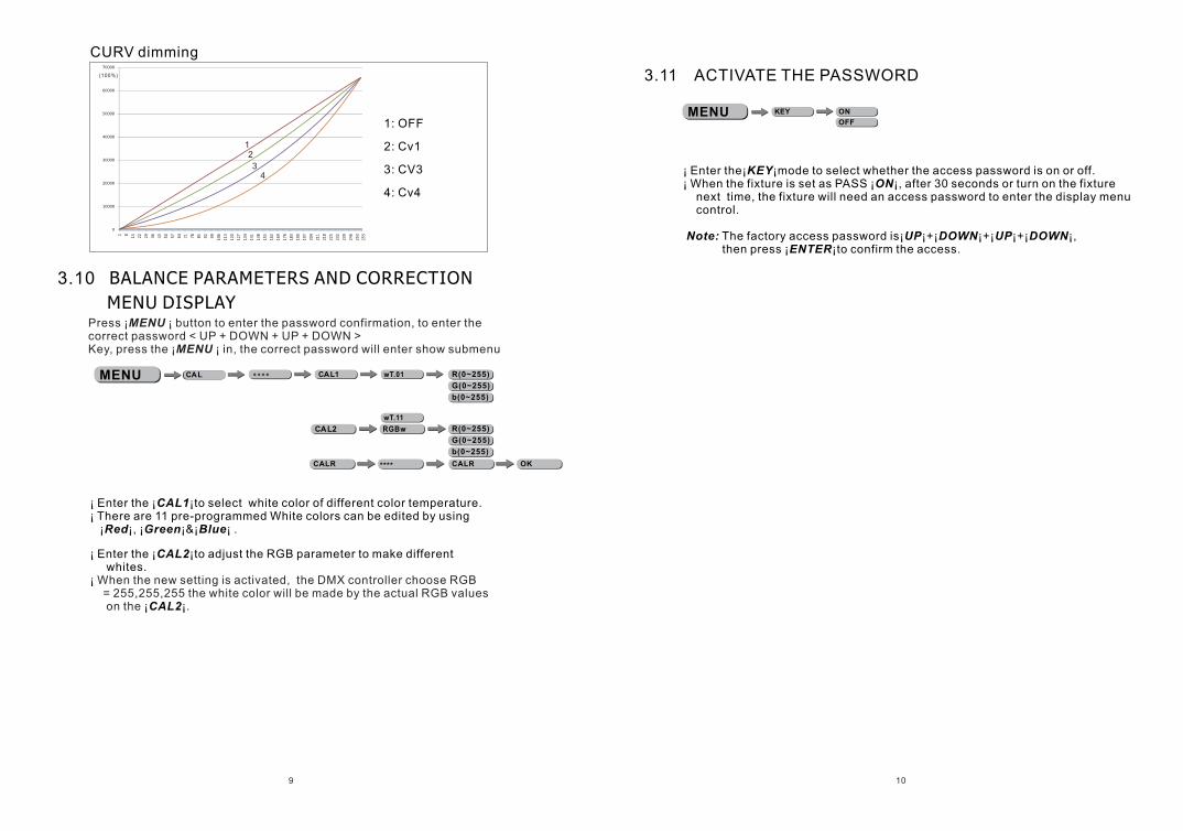
CURV dimming
1: OFF
2: Cv1
3: CV3
4: Cv4
12
34
(100%)
Press ¡MENU ¡ button to enter the password confirmation, to enter the correct password < UP + DOWN + UP + DOWN >Key, press the ¡MENU ¡ in, the correct password will enter show submenu
3.10 BALANCE PARAMETERS AND CORRECTION
MENU DISPLAY
¡ Enter the ¡CAL1¡to select white color of different color temperature.¡ There are 11 pre-programmed White colors can be edited by using ¡Red¡, ¡Green¡&¡Blue¡ .
¡ Enter the ¡CAL2¡to adjust the RGB parameter to make different whites.¡
¡CAL2¡
When the new setting is activated, the DMX controller choose RGB = 255,255,255 the white color will be made by the actual RGB values on the .
KEY ON
OFFMENU
3.11 ACTIVATE THE PASSWORD
¡ Enter the¡KEY¡mode to select whether the access password is on or off.¡ When the fixture is set as PASS ¡ON¡, after 30 seconds or turn on the fixture next time, the fixture will need an access password to enter the display menu control.
Note: The factory access password is¡UP¡+¡DOWN¡+¡UP¡+¡DOWN¡, then press ¡ENTER¡to confirm the access.