spectral efficiency improvement in ieee 802.11n mimo-ofdm
TRANSCRIPT
RADIOENGINEERING, VOL. XX, NO. X, XX 2013 1
Spectral Efficiency Improvement in IEEE 802.11n MIMO-OFDM WLAN Communication Systems using Compact Space-Multimode Diversity Stacked Circular
Microstrip Patch Antenna Arrays
Asuman Yavanoğlu1, Özgür Ertuğ1,Erdem Yazgan2
1 Gazi University, Electrical and Electronics Engineering Department, Telecommunications and Signal Processing Laboratory (TESLAB), Ankara, TURKEY
2 Hacettepe University, Electrical and Electronics Engineering Department, Ankara, TURKEY
[email protected], [email protected], [email protected]
Abstract. The support of high spectral efficiency MIMO spatial-multiplexing communication in OFDM-WLAN systems conforming to IEEE 802.11n standard requires the design and use of compact antennas and arrays with low correlation ports. For this purpose, compact space-multimode diversity provisioning stacked circular multimode microstrip patch antenna arrays (SCP-ULA) are proposed in this paper and their performance in terms of spatial and modal correlations, ergodic spectral efficiencies as well as compactness with respect to antenna arrays formed of vertically-oriented center-fed dipole elements (DP-ULA) and dominant-mode operating circular microstrip patch antennas (CP-ULA) are presented. The lower spatial and modal correlations and the consequent higher spectral efficiency of SCP-ULA with ML detection over statistically-clustered Kroenecker-based correlated Rayleigh fading channels with respect to DP-ULA and CP-ULA at significantly lower antenna and array sizes represents SCP-ULA as a promising solution for deployment in terminals, modems and access points of next-generation high-speed 802.11n MIMO-OFDM WLAN systems.
Keywords IEEE 802.11n MIMO-OFDM WLAN, spectral efficiency, correlation, multimode antenna, spatial multiplexing, Kroenecker channel model.
1. Introduction In the concurrent and next-generation communication
systems, the spectral efficiency and transmission quality can be vastly enhanced by multiple-input multiple-output (MIMO) communication techniques [1]. In communication systems employing MIMO spatial-multiplexing, higher data rates can be achieved when there are a large number of scatterers between the transmit and receive antennas i.e.
rich-scattering environment. However, the spatial correlation between transmit and receive antenna ports that is dependent on antenna-specific parameters such as the radiation patterns, the distance between the antenna elements as well as the channel characteristics such as unfavourable spatial distribution of scatterers and angular spread severely degrades the capacity and quality achievable by MIMO spatial-multiplexing systems.
The space consumption of MIMO antennas is especially
vital in applications such as access points, modems and end-user terminal equipments (laptops, PDAs etc.) of WLAN and WIMAX systems. When regularly spaced antenna elements are used in MIMO systems, the correlation between the antenna elements in a space diversity system and hence the channel capacity and transmission quality are dependent on the distance between antenna array elements, the number of antenna elements and the array geometry. However, due to the physical constraints and the concerns on ergonomics and aesthetics, the distance between antenna elements in practice can not be extended beyond a certain level which limits the use of space-only diversity MIMO spatial-multiplexing systems to achieve the desired spectral efficiencies and transmission qualities. As an alternative solution to achieve compactness in MIMO systems, the use of pattern diversity [2,3], multimode diversity [4,5], and polarization diversity [6,7] techniques in conjunction with space diversity are proposed in the literature.
Besides polarization diversity that is well-known,
multimode and pattern diversity techniques that are less addressed in antenna engineering community are achieved by using higher-order mode generation in antenna structures and in general microstrip, biconical, helical, spiral, sinous and log-periodic antenna structures are amenable to higher-order mode generation. In this manner, the higher-order modes generated in a single antenna structure with directional radiation patterns resulting in low
2 YAVANOĞLU ET AL., SPECTRAL EFFICIENCY IMPROVEMENT IN IEEE 802.11N SYSTEMS
spatial correlation in angle space are used as diversity ports in a MIMO system within a compact space. In pattern diversity on the other hand that is slightly different than multimode diversity, orthogonal radiation patterns generated on distinct antennas that are co-located at the phase-centers are generated and used as diversity ports.
In this work, a multimode stacked circular microstrip
patch antenna used in a uniform linear array structure (SCP-ULA) for MIMO-OFDM WLAN systems conforming to IEEE 802.11n standard is designed and the associated correlation, ergodic spectral efficiency and compactness with respect to omnidirectional dipole (DP-ULA) and circular microstrip uniform linear arrays (CP-ULA) operating in the dominant isotropic TM01 mode are analyzed. Section II. represents the 802.11n MIMO-OFDM WLAN details as well as the associated system and statistically-clustered Kroenecker-based correlated channel models for MIMO spatial-multiplexing. Section III. is dedicated to the design procedure of stacked circular microstrip antenna for IEEE 802.11n MIMO-OFDM WLAN communication in HFSSv.11@TM CAD program and the analysis of the marginal and superimposition radiation patterns as well as S-parameters and VSWR variations versus frequency respectively. In Section IV., the gains of SCP-ULA with respect to CP-ULA and DP-ULA in terms of spatial/modal correlations, ergodic spectral efficiency as well as compactness are presented. Finally, Section V. concludes the paper.
2. IEEE 802.11N WLANS AND ASSOCIATED SYSTEM/CHANNEL MODELS
The wireless local area network (WLAN) technology for medium-range indoor/outdoor wireless communications standardized by IEEE P802.11 working group has emerged from pre-802.11 standards towards spectrally-efficient and multipath-robust OFDM modulation based 802.11b and 802.11a/g with data rates increasing up to a maximum of 54 Mbps for 802.11a/g. These standards are limited to the use of single transmit and receive antenna at the access points and modems as well as laptops/PDAs in WLANs for end-users forming a SISO-OFDM (single-input single-output OFDM) channel. In the last decade, with the proliferation of MIMO spatial-multiplexing technology using multiple transmit and receive antennas achieving much higher data rates without sacrificing either bandwidth or transmit power with respect to SISO systems, IEEE 802.11 standard is later extended with the version 802.11n incorporating MIMO capability with the first amendment published in 2009 [8] proposing operation at lower and upper ISM bands of 2.4 GHz and 5.8 GHz with the corresponding bandwidths of 20 MHz and 40 Mhz respectively. By the use of MIMO spatial-multiplexing
technology, higher-order 64/128/256-QAM modulations, a 40 MHz channel bandwidth at 5.8 GHz that is double that of legacy IEEE 802.11 a/b/g systems, a cyclic prefix (CP) of 400 ns that is half of legacy systems which reduces symbol time and hence increases data rates, more efficient OFDM structure with 52 subcarriers with respect to 48 subcarriers in legacy systems, and frame -aggregation/block-acknowledgement protocol with higher packet sizes at the MAC layer [9,10], IEEE 802.11n standard sets forth the basis for multimedia-enabling high-throughput next-generation Wi-Fi networks.
(a)
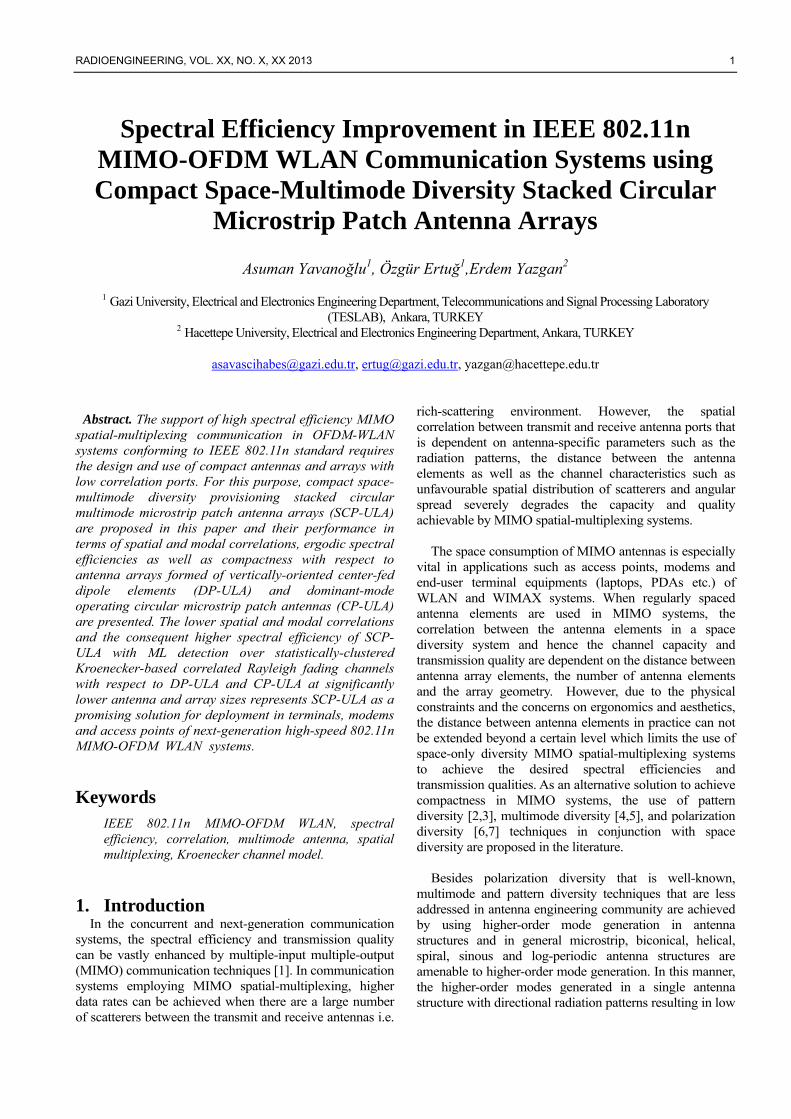
(b) Fig. 1. Transmitter and receiver diagrams of a MIMO-OFDM
WLAN system, (a): Transmitter (b): Receiver. The transmitter and receiver block diagrams of an IEEE
802.11n based MIMO-OFDM WLAN system is illustrated in Fig. 1. The binary data is first encoded by channel encoder after which the encoded bits are multiplexed into sub-streams, modulated, and transmitted from each
RADIOENGINEERING, VOL. XX, NO. X, XX 2013 3
antenna. At the receiver side, after a digital representation of N received signals is obtained by ADCs, the CP is removed and N-point DFT is performed per receiver branch. Since the MIMO-OFDM system turns into a narrow band flat-fading MIMO channel per sub-carrier over multipath fading channels, the received signal vector per sub-carrier is given by:
),(),()(),( kikiiki nsHy += (1)
where i and k are sub-carrier and symbol indices respectively. Here, )(iH represents NxM dimensional
channel matrix for i-th sub-carrier, ),( kis represents
modulated transmit symbol vectors for ith sub-carrier and ),( kin represents additive white Gaussian noise at the ith
subcarrier and kth symbol index with N independent and identically distributed (i.i.d) zero-mean complex elements
with variance of 2nσ .
Amongst the MIMO channel models proposed in the
literature such as deterministic models (ray-tracing, recorded impulse response etc.) or stochastic models (geometric ring, parametric, correlation-based etc.), we deploy as the channel model the statistically-clustered Kroenecker channel model for the characterization of the spatially-correlated MIMO channel in this work which has also been standardized for MIMO-OFDM IEEE 802.11n WLAN systems in [9]. Kroenecker model assumes seperability between transmit/receive spatial correlations and the same model is also used for the performance analysis of indoor MIMO systems with stacked circular microstrip patch antennas with pattern diversity in [3].
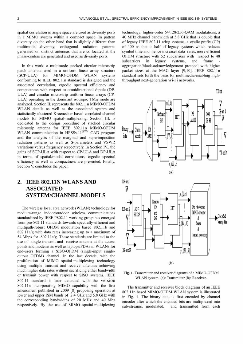
The general geometry of the statistically-clustered
Kroenecker model we employ throughout the sequel representing the clusters and the transmission paths is represented in Fig.2. For simplicity, only reflection from a single cluster is assumed in this work for the evaluation of the correlation and consequently spectral efficiencies, and the extension of the model to include a higher number of clusters is straightforward due to the additivity of spatial correlations.
The spatially-correlated channel matrix
cH in
Kroenecker model is formulated as:
NLOSLOS KK
KHHH
++
+=
1
1
1 (2)
and includes Rayleigh fading for K=0, Ricean fading for higher K values and also AWGN channel for K=∞ where
LOSH
and NLOSH
are LOS (line-of-sight) and NLOS
(nonline-of-sight) components respectively, K is the Ricean K-factor given by the ratio of the LOS component’s power over NLOS component’s power [1] and the NLOS channel matrix is defined as [9]:
2/12/1
twrNLOS RHRH =
(3)
l
l
l
l
l
l
l
l
Tx Rx
c
r r
dφ
Fig.2. Geometry of the clustered channel model representing
clusters and transmit/receive antenna arrays (4x4 array)
where cφ is the mean A.O.D. of the cluster
where
rR and tR denote the transmit and receive spatial
power correlation matrices respectively. The LOS component of the channel is also assumed to be rank one, and defined as [11]:
( ) ( )H
LOS tLOS,rLOS, Ω⋅Ω= aaH (4) where ( )Ωa is the array response as a function of the solid
angle ),( θφ=Ω , while tLOS,Ω and rLOS,Ω are
AoA/AoD corresponding to the LOS component at the transmitter and receiver respectively.
3. Design of Multimode Stacked Circular Patch (SCP) Microstrip Antenna
The multimode stacked circular microstrip patch antenna (SCP) proposed for IEEE 802.11n MIMO-OFDM WLAN application in this work has the upper antenna in the stack excited at the TM11 mode and the bottom antenna excited at
4 YAVANOĞLU ET AL., SPECTRAL EFFICIENCY IMPROVEMENT IN IEEE 802.11N SYSTEMS
the TM21 mode to meet the compactness requirements since the radius of a circular microstrip patch antenna scales up with the mode number m excited given by the formula [12]:
r
maεπλχ
2=
(5)
where mχ indicates the first zero of the derivative of the first
kind Bessel function of order m )(xJm as presented in Table
I.
Table 1. mχ for Different Modal Orders TM01 TM11 TM21 TM31 TM41 TM51 TM61
mχ 3.82 1.84 3.04 4.18 5.29 6.38 7.46
The far-field radiation patterns for a circular microstrip patch antenna excited at the mth mode is further given by [12]:
+=
→→−→φθ φθ ,, mm
rjk
m EEr
eE
f
[ ] ))(cos()()(2 011
0
, φφθ −−= −+ mzJzJakVj
E mmfm
m
m
[ ] ))(sin()cos()()(2 011
0
, φφθφ −+−= −+ mzJzJakVj
E mmfm
m
m
where λπ /2=fk
is the wavenumber, )(xJm is the
Bessel function of first kind of order m, a is the patch
radius, 0mV is the peak input voltage of mth mode, 0φ is the
reference azimuth angle for the feed of the circular patch, and )sin( θakz f= . Via these far-field radiation patterns,
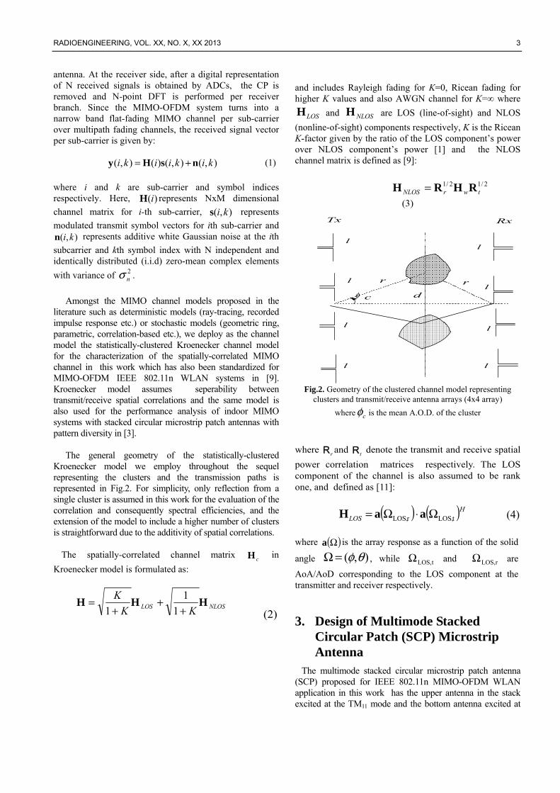
neglecting elevation spread that is acceptable for indoor propagation environments and assuming the look-direction coincident with broadside is 2/πθ = , only θ components of the far-field radiation pattern dependent on the azimuth angle φ in (6) remains. Azimuth plane
radiation patterns for mode orders m=1,2,3 are presented in Fig. 3.
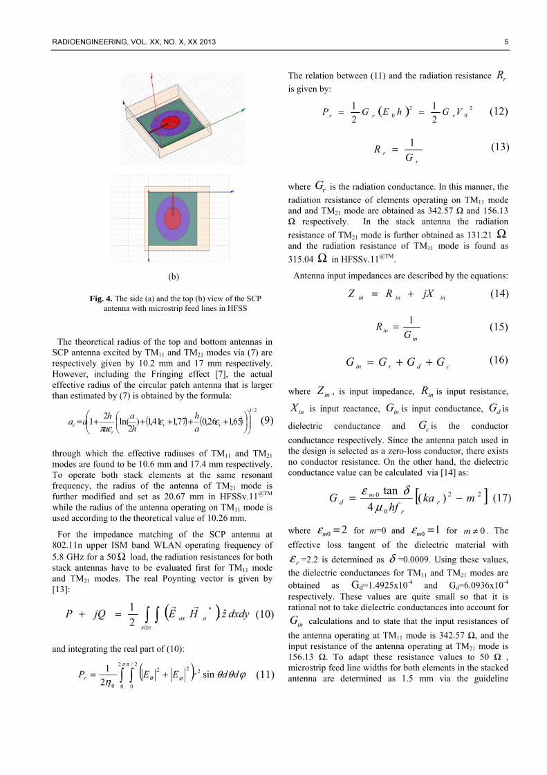
The SCP antenna fed by microstrip feed lines designed in HFSSv.11 3D EM design and analysis software is presented in Fig. 4. To stay at the proper point of the trade-off between antenna bandwidth improvement and the antenna efficiency decrease/pattern distortion as well as to keep mutual coupling low, the distances between ground and bottom antenna as well as between circular antennas are kept as 0.5 mm. To ensure high radiation efficiency, the
dielectric constant of the substrate is further chosen low as
rε =2.2.
(a)
(b)
(c)
(6)
(7)
(8)
Fig. 3. Radiation patterns of multimode circular patch antennas (a): TM11 mode (b):TM21 mode (c):TM31 mode
RADIOENGINEERING, VOL. XX, NO. X, XX 2013 5
(b)
The theoretical radius of the top and bottom antennas in SCP antenna excited by TM11 and TM21 modes via (7) are respectively given by 10.2 mm and 17 mm respectively. However, including the Fringing effect [7], the actual effective radius of the circular patch antenna that is larger than estimated by (7) is obtained by the formula:
( ) ( )2/1
65,126,077,141,1)2
ln(2
1
+++++= rr
re a
h
h
a
a
haa εε
επ
through which the effective radiuses of TM11 and TM21 modes are found to be 10.6 mm and 17.4 mm respectively. To operate both stack elements at the same resonant frequency, the radius of the antenna of TM21 mode is further modified and set as 20.67 mm in HFSSv.11@TM while the radius of the antenna operating on TM11 mode is used according to the theoretical value of 10.26 mm.
For the impedance matching of the SCP antenna at 802.11n upper ISM band WLAN operating frequency of 5.8 GHz for a 50 Ω load, the radiation resistances for both stack antennas have to be evaluated first for TM11 mode and TM21 modes. The real Poynting vector is given by [13]:
( ) =+size
aax dxdyzHEjQP ˆ.2
1 *
and integrating the real part of (10):
( ) ϕθθη
π π
ϕθ ddrEEPr sin2
1 22
0
2/
0
22
0 +=
The relation between (11) and the radiation resistance rR
is given by:
( ) 20
20 2
1
2
1VGhEGP rrr ==
rr G
R1=
where rG is the radiation conductance. In this manner, the
radiation resistance of elements operating on TM11 mode and and TM21 mode are obtained as 342.57 Ω and 156.13 Ω respectively. In the stack antenna the radiation
resistance of TM21 mode is further obtained as 131.21 Ω and the radiation resistance of TM11 mode is found as
315.04 Ω in HFSSv.11@TM.
Antenna input impedances are described by the equations:
ininin jXRZ +=
inin G
R1=
cdrin GGGG ++=
where inZ , is input impedance, inR is input resistance,
inX is input reactance, inG is input conductance, dG is
dielectric conductance and cG is the conductor
conductance respectively. Since the antenna patch used in the design is selected as a zero-loss conductor, there exists no conductor resistance. On the other hand, the dielectric conductance value can be calculated via [14] as:
[ ]22
0
0 )(4
tanmka
hfG r
r
md −=
μδε
where 20 =mε for m=0 and 10 =mε for 0≠m . The
effective loss tangent of the dielectric material with
rε =2.2 is determined as δ =0.0009. Using these values,
the dielectric conductances for TM11 and TM21 modes are obtained as Gd=1.4925x10⁻⁴ and Gd=6.0936x10⁻⁴ respectively. These values are quite small so that it is rational not to take dielectric conductances into account for
inG calculations and to state that the input resistances of
the antenna operating at TM11 mode is 342.57 Ω, and the input resistance of the antenna operating at TM21 mode is 156.13 Ω. To adapt these resistance values to 50 Ω , microstrip feed line widths for both elements in the stacked antenna are determined as 1.5 mm via the guideline
Fig. 4. The side (a) and the top (b) view of the SCP antenna with microstrip feed lines in HFSS
(15)
(17)
(9)
(10)
(11)
(12)
(13)
(14)
(16)
6 YAVANOĞLU ET AL., SPECTRAL EFFICIENCY IMPROVEMENT IN IEEE 802.11N SYSTEMS
equations in [15] such that both stack elements are matched to 50Ω input resistance.
In the design of SCP antenna, the antenna reactances are further calculated via :
ΔΔ+
−
+−=
∞
=
∞
= 1
2
220
20
20
200
20
220
)sin(2
)(
1
mm mem
m
ein
n
n
kkakja
kj
kahjwX
ππρ
πμ
and found as -j162.7 Ω and –j107.13Ω for TM11 and TM21
modes respectively. In the stack antenna, the evaluation of the reactances of antenna with TM21 mode is obtained as j77.316 while that of TM11 mode is found as j123.25Ω that are quite high values for matching and can be minimized by optimizing the length of the microstrip feed lines.
The characteristic impedance of the feed line can be found depending on the size of the microstrip feed line by using:
≥
+++
≤
+
= −
)1/(444.1ln667.0393.1
)1/(,25.08
ln2
10
hLh
L
h
L
hLh
L
L
h
Z
re
re
εη
επη
where L is microstrip feed line width and h is height of dielectric substrate of microstrip line. Effective dielectric constant is also calculated via:
)/(2
1
2
1hLFrere
re
−++= εεε
According to the desired characteristic impedance value, the ratio of the microstrip feedline width (L) to dielectric substrate height (h) is calculated via:
≥
−+−
−+−−−
<−
=)1/(,
61.039.0)1ln(
2
1)12ln(1
)2/(,2)2exp(
)exp(8
hLBBB
hLA
A
h
L
rr
r
εεε
where A and B are:
r
rr
rr
ZB
ZA
επ
εεεε
0
0
2
377
11.023.0
1
1
2
1
60
=
+
+−++=
With the height of the dielectric substrate h=0.5mm, the line width L is calculated as 1.55mm via (23) for the microstrip feed lines and in this manner, the antenna reactances of TM11 mode and TM21 modes are minimized to j11.513 Ω and j4.5072 Ω respectively with the corresponding antenna input impedances obtained finally obtained and used in S-parameter and VSWR analysis as
Zin1=45.507+j11.513Ω and Zin2=50.678+j4.5072 Ω for TM11 and TM21 modes respectively.
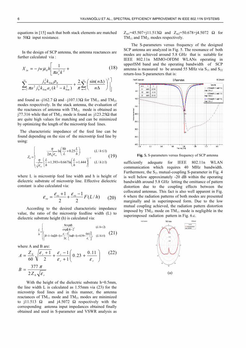
The S-parameters versus frequency of the designed SCP antenna are analyzed in Fig. 5. The resonance of both modes are achieved around 5.8 GHz that is suitable for IEEE 802.11n MIMO-OFDM WLANs operating in upperISM band and the operating bandwidth of SCP antenna is measured to be around 55 MHz via S11 and S22 return-loss S-parameters that is:
Fig. 5. S-parameters versus frequency of SCP antenna
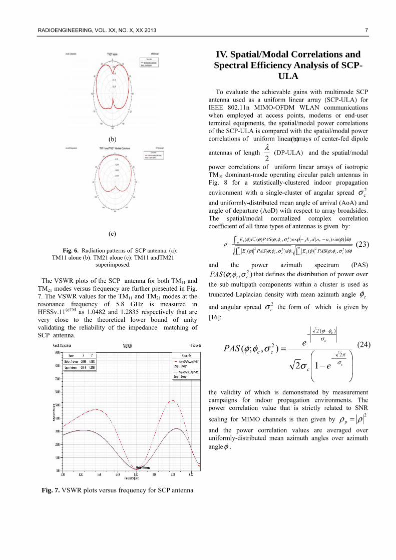
sufficiently adequate for IEEE 802.11n WLAN communication which requires 40 MHz bandwidth. Furthermore, the S21 mutual-coupling S-parameter in Fig. 4 is well below approximately -20 dB within the operating bandwidth around 5.8 GHz letting the omittance of pattern distortion due to the coupling effects between the collocated antennas. This fact is also well apparent in Fig. 6 where the radiation patterns of both modes are presented marginally and in superimposed form. Due to the low mutual coupling achieved, the radiation pattern distortion imposed by TM21 mode on TM11 mode is negligible in the superimposed radiation pattern in Fig. 6.c.
(a)
(18)
(20)
(21)
(19)
(22)
RADIOENGINEERING, VOL. XX, NO. X, XX 2013 7
(b) (b)
(c)
The VSWR plots of the SCP antenna for both TM11 and TM21 modes versus frequency are further presented in Fig. 7. The VSWR values for the TM11 and TM21 modes at the resonance frequency of 5.8 GHz is measured in HFSSv.11@TM as 1.0482 and 1.2835 respectively that are very close to the theoretical lower bound of unity validating the reliability of the impedance matching of SCP antenna.
Fig. 7. VSWR plots versus frequency for SCP antenna
IV. Spatial/Modal Correlations and Spectral Efficiency Analysis of SCP-
ULA
To evaluate the achievable gains with multimode SCP antenna used as a uniform linear array (SCP-ULA) for IEEE 802.11n MIMO-OFDM WLAN communications when employed at access points, modems or end-user terminal equipments, the spatial/modal power correlations of the SCP-ULA is compared with the spatial/modal power correlations of uniform linear arrays of center-fed dipole
antennas of length 2
λ (DP-ULA) and the spatial/modal
power correlations of uniform linear arrays of isotropic TM01 dominant-mode operating circular patch antennas in Fig. 8 for a statistically-clustered indoor propagation
environment with a single-cluster of angular spread 2cσ
and uniformly-distributed mean angle of arrival (AoA) and angle of departure (AoD) with respect to array broadsides. The spatial/modal normalized complex correlation coefficient of all three types of antennas is given by:
( )
−−
−−−
=π
π
π
π
π
π
φσφφφφσφφφ
φφσφφφφρ
dPASEdPASE
dnndjkPASEE
cccc
fcc
),;()(.),;()(
)sin()(exp),;()()(
22
222
1
122*
21
and the power azimuth spectrum (PAS)
),;( 2ccPAS σφφ that defines the distribution of power over
the sub-multipath components within a cluster is used as
truncated-Laplacian density with mean azimuth angle cφ
and angular spread 2cσ the form of which is given by
[16]:
−
=−
−−
c
c
c
e
ePAS
c
cc
σπ
σφφ
σ
σφφ2
)(2
2
12
),;(
the validity of which is demonstrated by measurement campaigns for indoor propagation environments. The power correlation value that is strictly related to SNR
scaling for MIMO channels is then given by 2ρρ =p
and the power correlation values are averaged over uniformly-distributed mean azimuth angles over azimuth angleφ .
Fig. 6. Radiation patterns of SCP antenna: (a): TM11 alone (b): TM21 alone (c): TM11 andTM21
superimposed.
(24)
(23)

8 YAVANOĞLU ET AL., SPECTRAL EFFICIENCY IMPROVEMENT IN IEEE 802.11N SYSTEMS
Fig. 8. Power correlation values of DP-ULA, CP-ULA and
SCP-ULA averaged over azimuth angle for a 2x2 array.
The power correlation values of the SCP antenna for all
angular spread values and spatial/modal combinations in the densest configuration where stack antennas are nearby in the most compact scenario allowed by the physical radius of the bottom antenna for 2x2 configuration as presented in Fig. 8 are much lower than that of the two nearest antennas spaced at the patch radius of SCP bottom
antenna in - length DP-ULA and CP-ULA which dictates
spectral efficiency gains for MIMO spatial-multiplexing.
In Fig. 9, the power correlations of SCP-ULA versus mean azimuth angle for two different values of low (50) and high (200). angular spread are presented. For all angular spread values, DP-ULA has the maximum correlation values in comparison with CP and SCP at broadside, where the cluster is at the center of the antenna arrays and the oscillations of the patch antennas (SCP-1122 and SCP-1222) decrease directly with the increase in angular spread. Besides, the maximum value of the correlations for all antennas is inversely proportional with angular spread.
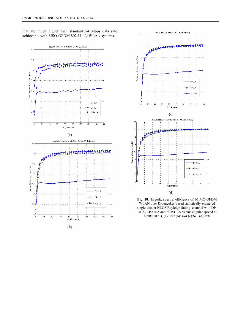
The ergodic spectral efficiencies in bps/Hz of MIMO-
OFDM WLAN system with DP-ULA, CP-ULA and SCP-ULA versus angular spread for 2x2, 4x4, 6x6 and 8x8 configurations are further presented in Fig. 10 over single-cluster Kroenecker-model NLOS Rayleigh fading channel via [17]:
+=
=
cN
i
HccN
ce M
SNR
NE
12 detlog
1 HHIη
where the correlated channel matrix cH has the Kroenecker
form [18-20]; 2/12/1TXwRXc RHRH = , in terms of the receive
and transmit normalized power correlation matrices
RXR and TXR .
(a)
(b)
Fig. 9. Power correlation values of DP-ULA, CP-ULA and SCP-ULA versus mean azimuth angle (a): 50 (b) 200
and the elementwise-independent MN × Wishart–type
random matrix wH with elements distributed as )1,0(CN .
For 22× and 44 × configurations, the SCP-ULA has much higher spectral efficiency than DP-ULA and slightly higher spectral efficiency than CP-ULA. On the other hand, for 6x6 and 8x8 configurations, CP-ULA and SCP-ULA have nearly the same spectral efficiencies which is also higher than DP-ULA. Furthermore, based on the spectral efficiency results presented in Fig.10, data rates achievable with SCP-ULA conforming to IEEE 802.11n standards with 40MHz bandwidth at 5.8 GHz for 2x2, 4x4, 6x6 and 8x8 array configurations are 164 Mbps, 324 Mbps, 480Mbps, 644Mbps respectively for high angular spreads
(25)
RADIOENGINEERING, VOL. XX, NO. X, XX 2013 9
that are much higher than standard 54 Mbps data rate achievable with SISO-OFDM 802.11 a/g WLAN systems.
(a)
(b)
(c)
(d)
Fig. 10: Ergodic spectral efficiency of MIMO-OFDM WLAN over Kroenecker-based statistically-clustered
single-cluster NLOS Rayleigh fading channel with DP-ULA, CP-ULA and SCP-ULA versus angular spread at
SNR=10 dB, (a): 2x2 (b): 4x4 (c):6x6 (d):8x8
10 YAVANOĞLU ET AL., SPECTRAL EFFICIENCY IMPROVEMENT IN IEEE 802.11N SYSTEMS
(a)
(b)
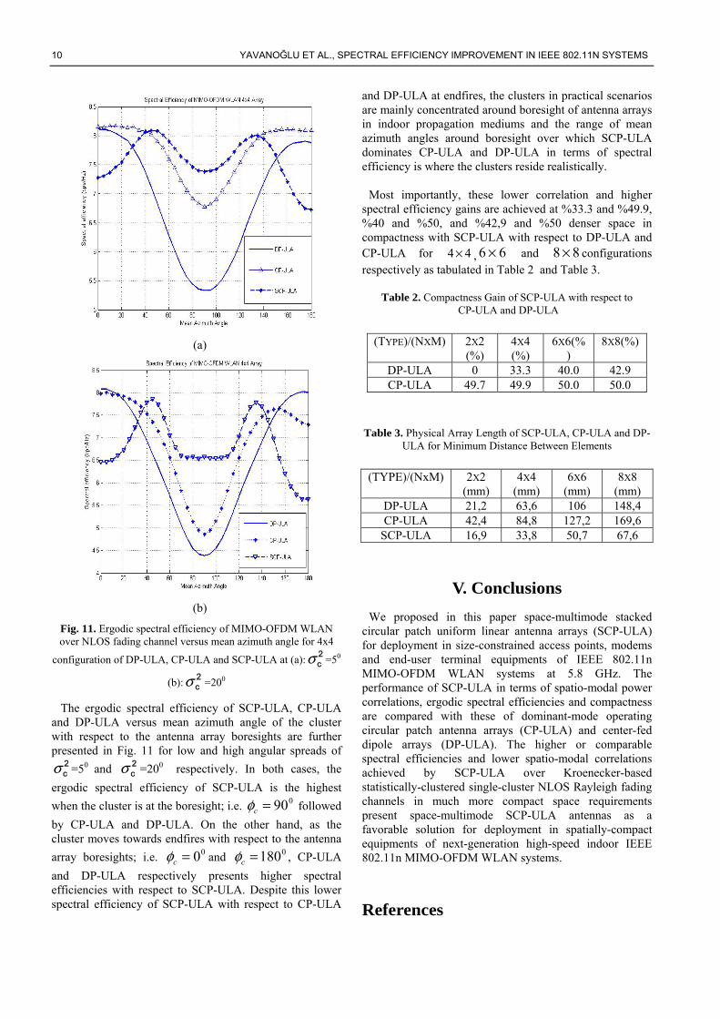
Fig. 11. Ergodic spectral efficiency of MIMO-OFDM WLAN over NLOS fading channel versus mean azimuth angle for 4x4
configuration of DP-ULA, CP-ULA and SCP-ULA at (a):2cσ =50
(b):2cσ =200
The ergodic spectral efficiency of SCP-ULA, CP-ULA and DP-ULA versus mean azimuth angle of the cluster with respect to the antenna array boresights are further presented in Fig. 11 for low and high angular spreads of
2cσ =50 and 2
cσ =200 respectively. In both cases, the
ergodic spectral efficiency of SCP-ULA is the highest
when the cluster is at the boresight; i.e. 090=cφ followed
by CP-ULA and DP-ULA. On the other hand, as the cluster moves towards endfires with respect to the antenna
array boresights; i.e. 00=cφ and 0180=cφ , CP-ULA
and DP-ULA respectively presents higher spectral efficiencies with respect to SCP-ULA. Despite this lower spectral efficiency of SCP-ULA with respect to CP-ULA
and DP-ULA at endfires, the clusters in practical scenarios are mainly concentrated around boresight of antenna arrays in indoor propagation mediums and the range of mean azimuth angles around boresight over which SCP-ULA dominates CP-ULA and DP-ULA in terms of spectral efficiency is where the clusters reside realistically.
Most importantly, these lower correlation and higher
spectral efficiency gains are achieved at %33.3 and %49.9, %40 and %50, and %42,9 and %50 denser space in compactness with SCP-ULA with respect to DP-ULA and CP-ULA for 44 × , 66 × and 88 × configurations respectively as tabulated in Table 2 and Table 3.
Table 2. Compactness Gain of SCP-ULA with respect to CP-ULA and DP-ULA
(TYPE)/(NXM) 2X2
(%) 4X4
(%) 6X6(%
) 8X8(%)
DP-ULA 0 33.3 40.0 42.9 CP-ULA 49.7 49.9 50.0 50.0
Table 3. Physical Array Length of SCP-ULA, CP-ULA and DP-
ULA for Minimum Distance Between Elements
(TYPE)/(NxM) 2X2
(mm) 4X4
(mm) 6X6
(mm) 8X8
(mm) DP-ULA 21,2 63,6 106 148,4 CP-ULA 42,4 84,8 127,2 169,6
SCP-ULA 16,9 33,8 50,7 67,6
V. Conclusions
We proposed in this paper space-multimode stacked circular patch uniform linear antenna arrays (SCP-ULA) for deployment in size-constrained access points, modems and end-user terminal equipments of IEEE 802.11n MIMO-OFDM WLAN systems at 5.8 GHz. The performance of SCP-ULA in terms of spatio-modal power correlations, ergodic spectral efficiencies and compactness are compared with these of dominant-mode operating circular patch antenna arrays (CP-ULA) and center-fed dipole arrays (DP-ULA). The higher or comparable spectral efficiencies and lower spatio-modal correlations achieved by SCP-ULA over Kroenecker-based statistically-clustered single-cluster NLOS Rayleigh fading channels in much more compact space requirements present space-multimode SCP-ULA antennas as a favorable solution for deployment in spatially-compact equipments of next-generation high-speed indoor IEEE 802.11n MIMO-OFDM WLAN systems.
References
RADIOENGINEERING, VOL. XX, NO. X, XX 2013 11
[1] I. E. TELATAR. Capacity of Multi-antenna Gaussian Channels. European Transactions on Telecommunications, vol. 10, pp. 585–596, November 1999. [2] G. J. FOSCHINI AND M. GANS, On limits of wireless communications in a fading environment when using multiple antennas. Wireless Personal Communications, vol. 6, pp. 311–355, March 1998. [3] A. FORENZA and R. W. HEATH. Benefit of Pattern Diversity via Two-Element Array of Circular Patch Antennas in Indoor Clustered MIMO Channels. IEEE Transactions on Communications, vol. 54, no. 5, pp. 943-954, May 2006. [4] M. SANCHEZ-FERNANDEZ, E. RAJO-IGLESIAS, O. QUEVEDO-TERUEL, M. L. PABLO-GONZALEZ. Spectral Efficiency in MIMO Systems Using Space and Pattern Diversities Under Compactness Constraints. IEEE Transactions on Vehicular Technology, vol. 57, no.3, pp. 1637-1645, May 2008. [5] T. SVANTESSON. Correlation and Channel Capacity of MIMO Systems Employing Multimode Antennas. IEEE Transactions on Vehicular Technology, vol. 51, no. 6, pp. 1304-1312, November 2002. [6] A. MUKHERJEE and H. M. KWON. Compact Multi-user Wideband MIMO System Using Multiple-Mode Microstrip Antennas. Proceedings of Vehicular Technology Conference Spring- 2007, pp. 584-588, April 2007. [7] C. WALDSCHMIDT, C. KUHNERT, S. SCHULTEIS, and W. WIESBECK, Compact MIMO-Arrays Based on Polarization-Diversity. Proceedings of IEEE Antennas and Propagation Symposium, vol. 2, pp. 499-502, June 2003. [8] IEEE 802.11n-2009—Amendment 5: Enhancements for Higher Throughput. IEEE-SA. 29 October 2009. doi:10.1109/IEEESTD.2009.5307322. [9] IEEE P802.11n Wireless LANs: TGn Channel Models. IEEE-SA. May
10 2004. doc.: IEEE 802.11-03/940r4. [10] Wi-Fi CERTIFIED n: Longer-Range, Faster-Throughput, Multimedia-Grade Wi-Fi® Networks, Wi-Fi Alliance. September 2009. [11] A. Paulraj, R. Nabar, and D. Gore, Introduction to Space-Time Wireless Communications. New York: Cambridge University Press, 2003. [12] T. SVANTESSON. On the Capacity and Correlation of Multi-Antenna Systems Employing Multiple Polarizations. Proceedings of IEEE Antennas and Propagation Symposium, vol. 3, pp. 202-205, June 2002. [13] R. G. VAUGHAN. Two-Port Higher Mode Circular Microstrip Antennas. IEEE Transactions on Antennas and Propagation, vol. 36, no. 3, pp. 309-321, March 1988. [14] R. GARG, P. BHARTIA, I. BAHL. Microstrip Antenna Design Handbook. Artech House, 2001. [15] C.A. BALANIS. Antenna Theory: Analysis and Design, 2nd ed. United States of America, John Wiley&Sons Inc., 1997. [16] J. BAHL. Lumped Elements for RF and Microwave Circuits. Boston, Artech House, 2003. [17] A. VAN ZELST, R. VAN NEE and G. A. AWATER. Space-Division Multiplexing for OFDM Systems. IEEE Vehicular Technology Conference – Spring, vol.2, pp. 1070-1074, May 2000. [18] C. N. CHUAH, J. M. KAHN and D. N. C. TSE. Capacity of Multi-antenna Array Systems in Indoor Wireless Environments. Proceedings of GLOBECOM’98, vol. 4, pp. 1894-1899, Sidney, Australia, November 1998. [19] A. GOLDSMITH, MIMO Wireless Communications, Cambridge University Press, 2007. [20] A. VAN ZELST. Space-Division Multiplexing Algorithms. 10th Mediterranean Electrotechnical Conference 2000, MELECON 2000, Cyprus, May 2000, Vol.3, pp. 1218-1221.