spectra enhanced 7 series ip ptz look-up camera
TRANSCRIPT

Spectra® Enhanced 7
Series IP PTZ Look-Up
Camera
Installation Manual
C6687M (2/20)
S7230L-PW
S7240L-PW
S7820L-PW

2
Contents
Important Safety Instructions ........................................................................................................................................................ 3
Important Notices ......................................................................................................................................................................... 4
Regulatory Notices [FCC Class A] ................................................................................................................................. 4
Radio and Television Interference ................................................................................................................................. 4
Legal Notice [Audio Notice] ............................................................................................................................................ 4
Video Quality Caution .................................................................................................................................................... 4
Frame Rate Notice Regarding User Selected Options ................................................................................................... 4
Open Source Software ................................................................................................................................................... 5
Korean Class A EMC ..................................................................................................................................................... 5
ESD Warning ................................................................................................................................................................. 5
Warranty ........................................................................................................................................................................ 5
Network Topology Statement ......................................................................................................................................... 5
Description ................................................................................................................................................................................... 6
Getting Started ............................................................................................................................................................................. 6
Parts Lists .................................................................................................................................................................................... 7
Product Overview ......................................................................................................................................................................... 8
Installation .................................................................................................................................................................................. 10
Pelco Mounts ............................................................................................................................................................................. 10
Pelco Troubleshooting Contact Information ............................................................................................................................... 14
Note for Dimension Drawings ..................................................................................................................................................... 14

3
Important Safety Instructions
1. Read these instructions.
2. Keep these instructions.
3. Heed all warnings.
4. Follow all instructions.
5. Clean only with dry cloth.
6. Do not install near any heat sources such as radiators, heat registers, stoves, or other apparatus (including
amplifiers) that produce heat.
7. Only use attachments/accessories specified by the manufacturer.
8. Refer all servicing to qualified service personnel. Servicing is required when the apparatus has been damaged in any
way, such as power-supply cord or plug is damaged, liquid has been spilled or objects have fallen into the apparatus,
does not operate normally, or has been dropped.
9. Installation should be done only by qualified personnel and conform to all local codes.
10. Use only installation methods and materials capable of supporting four times the maximum specified load.
11. Use stainless steel hardware to fasten the mount to outdoor surfaces.
12. To prevent damage from water leakage when installing a mount outdoors on a roof or wall, apply sealant around the
bolt holes between the mount and mounting surface.
13. The mounting height above ground level shall be more than 3 meter for wall mount height.
CAUTION: These servicing instructions are for use by qualified service personnel only. To reduce the risk of electric shock do
not perform any servicing other that contained in the operating instructions unless you are qualified to do so.
Only use replacement parts recommended by Pelco.
The product and/or manual may bear the following marks:
This symbol indicates that dangerous voltage constituting a risk of electric shock is present within this unit.
CAUTION: RISK OF ELECTRIC SHOCK. DO NOT OPEN.
This symbol indicates that there are important operating and maintenance instructions in the literature accompanying this unit
WARNING: HAZARDOUS MOVING PARTS. KEEP FINGERS AND OTHER BODY PARTS AWAY.
Denotes Class II double insulated device.
WARNING: This product is sensitive to Electrostatic Discharge (ESD). To avoid ESD damage to this product, use ESD safe practices during installation. Before touching, adjusting or handling this product, correctly attach an ESD wrist strap to your wrist and appropriately discharge your body and tools. For more information about ESD control and safe handling practices of electronics, please refer to ANSI/ESD S20.20-1999 or contact the Electrostatic Discharge Association (www.esda.org).

4
Important Notices
REGULATORY NOTICES [FCC CLASS A]
This device complies with Part 15 of the FCC Rules. Operation is subject to the following two conditions: (1) this device may
not cause harmful interference, and (2) this device must accept any interference received, including interference that may
cause undesired operation.
RADIO AND TELEVISION INTERFERENCE
This equipment has been tested and found to comply with the limits of a Class A digital device, pursuant to Part 15 of the FCC
rules. These limits are designed to provide reasonable protection against harmful interference when the equipment is operated
in a commercial environment. This equipment generates, uses, and can radiate radio frequency energy and, if not installed
and used in accordance with the instruction manual, may cause harmful interference to radio communications. Operation of
this equipment in a residential area is likely to cause harmful interference in which case the user will be required to correct the
interference at his own expense.
Changes and Modifications not expressly approved by the manufacturer or registrant of this equipment can void your authority
to operate this equipment under Federal Communications Commission’s rules.
Cet appareil numérique de la classe A est conforme à la norme NMB-003 du Canada.
LEGAL NOTICE [AUDIO NOTICE]
SOME PELCO EQUIPMENT CONTAINS, AND THE SOFTWARE ENABLES, AUDIO/VISUAL AND RECORDING
CAPABILITIES, THE IMPROPER USE OF WHICH MAY SUBJECT YOU TO CIVIL AND CRIMINAL PENALTIES.
APPLICABLE LAWS REGARDING THE USE OF SUCH CAPABILITIES VARY BETWEEN JURISDICTIONS AND MAY
REQUIRE, AMONG OTHER THINGS, EXPRESS WRITTEN CONSENT FROM RECORDED SUBJECTS. YOU ARE SOLELY
RESPONSIBLE FOR INSURING STRICT COMPLIANCE WITH SUCH LAWS AND FOR STRICT ADHERENCE TO ANY/ALL
RIGHTS OF PRIVACY AND PERSONALTY. USE OF THIS EQUIPMENT AND/OR SOFTWARE FOR ILLEGAL
SURVEILLANCE OR MONITORING SHALL BE DEEMED UNAUTHORIZED USE IN VIOLATION OF THE END USER
SOFTWARE AGREEMENT AND RESULT IN THE IMMEDIATE TERMINATION OF YOUR LICENSE RIGHTS
THEREUNDER.
NOTE: Improper use of audio/visual recording equipment may subject you to civil and criminal penalties. Applicable laws
regarding the use of such capabilities vary between jurisdictions and may require, among other things, express written consent
from the recorded subjects. You are solely responsible for insuring strict compliance with such laws and for strict adherence to
any/all right of privacy and personality.
VIDEO QUALITY CAUTION
FRAME RATE NOTICE REGARDING USER SELECTED OPTIONS
Pelco systems are capable of providing high quality video for both live viewing and playback. However, the systems can be
used in lower quality modes, which can degrade picture quality, to allow for a slower rate of data transfer and to reduce the
amount of video data stored. The picture quality can be degraded by either lowering the resolution, reducing the picture rate,
or both. A picture degraded by having a reduced resolution may result in an image that is less clear or even indiscernible. A
picture degraded by reducing the picture rate has fewer frames per second, which can result in images that appear to jump or
move more quickly than normal during playback. Lower frame rates may result in a key event not being recorded by the
system.
Judgment as to the suitability of the products for users' purposes is solely the users' responsibility. Users shall determine the
suitability of the products for their own intended application, picture rate and picture quality. In the event users intend to use
the video for evidentiary purposes in a judicial proceeding or otherwise, users should consult with their attorney regarding any
particular requirements for such use.

5
OPEN SOURCE SOFTWARE
This product includes certain open source or other software originated from third parties that is subject to the GNU General
Public License (GPL), GNU Library/Lesser General Public License (LGPL) and different and/or additional copyright licenses,
disclaimers, and notices.
The exact terms of GPL, LGPL, and some other licenses are provided to you with this product. Please refer to the exact terms
of the GPL and LGPL at http://www.fsf.org (Free Software Foundation) or http://www.opensource.org (Open Source Initiative)
regarding your rights under said license. You may obtain a complete corresponding machine-readable copy of the source code
of such software under the GPL or LGPL by sending your request to [email protected]; the subject line should read
Source Code Request. You will then receive an email with a link for you to download the source code.
This offer is valid for a period of three (3) years from the date of the distribution of this product by Pelco.
KOREAN CLASS A EMC
ESD WARNING
WARNING: This product is sensitive to Electrostatic Discharge (ESD). To avoid ESD damage to this product, use ESD safe practices during installation. Before touching, adjusting or handling this product, correctly attach an ESD wrist strap to your wrist and appropriately discharge your body and tools. For more information about ESD control and safe handling practices of electronics, please refer to ANSI/ESD S20.20-1999 or contact the Electrostatic Discharge Association (www.esda.org).
WARRANTY
For information about Pelco’s product warranty and thereto related information, refer to www.pelco.com/warranty.
NETWORK TOPOLOGY STATEMENT
IMPORTANT NOTE. PLEASE READ. The network implementation is shown as a general representation only and is not
intended to show a detailed network topology. Your actual network will differ, requiring changes or perhaps additional network
equipment to accommodate the system as illustrated. Please contact your local Pelco representative to discuss your specific
requirements.

6
Description
The Spectra® Enhanced Series 7 of high-speed IP PTZ IR look-up cameras provide top tier image quality, performance, and
intelligent embedded features for state-of-the-art surveillance solutions. Low latency video and control make the camera
incredibly easy to control. Direct Drive closed loop control enables blazing pan and tilt speeds up to 300 (TBD) degree/ second
to position the camera on target avoiding perceived PT delays so that critical forensic evidence is captured. Direct Drive closed
loop systems have advantages such as limited wear and tear and maintenance, silent, extremely accurate positioning, and the
camera always knows its position.
The Spectra Enhanced Series 7 IP PTZ IR look-up camera is easy to install, offers flexible mounting options, and uses a
standard Web browser for easy remote setup and administration.
The Spectra Enhanced Series 7 IP PTZ IR look-up camera easily connects to Pelco IP and hybrid systems such as
VideoXpert and Digital Sentry version 7.3 (or later). The camera also conforms with ONVIF Profile S, Profile G, and Profile T
for connection with third-party software. Pelco offers an Application Programming Interface (API) and Software Developer’s Kit
(SDK) for interfacing with Pelco’s IP cameras.
This document describes the installation and initial setup procedures to begin operating the camera. For more information
about operating your camera, refer to the operation manual specific to the product.
NOTE: For additional information about Spectra Enhanced Series 7 IP PTZ IR camera product documentation in English and
other languages, go to www.pelco.com and navigate to the Spectra Enhanced Series 7 website.
Getting Started
Before installing your device, thoroughly familiarize yourself with the information in the installation section of this manual.
NOTES
• Pelco recommends connecting the device to a network that uses Dynamic Host Configuration Protocol (DHCP)
server to address devices.
• To ensure secure access, place the device behind a firewall when it is connected to a network.
• Ensure power source used is 48VDC, 24VAC or PoE BT.
NOTE:
The product is intended to be supplied by a Listed Power Unit marked "L.P.S." (or "Limited Power Source")
and rated output:
24Vac, 50/60Hz, 4.3A, 48Vdc, 1.9A or PoE BT, 1.3A (S7230L-PW)
24Vac, 50/60Hz, 4.3A, 48Vdc, 1.9A or PoE BT,1.3A (S7820L-PW)
24 Vac, 50/60Hz, 4.3A, 48Vdc, 1.9A or PoE BT 1.3A (S7240L-PW)
The product shall be installed by a qualified service person and the installation shall conform to all local
codes.
If a Class I adapter or switch is used to provided power, be sure that the power cord is firmly plugged into
the socket and confirm the main earth connection.

7
Parts Lists
SUPPLIED PARTS LIST
QTY DESCRIPTION
1 IP PTZ Outdoor Camera
1 Pin-in T-20 Torx Star Wrench
1 Pin-in T-6 Torx Star Wrench
1 18-pin Terminal Block
1 2-pin Terminal Block
1 Printed Installation Manual, Important Safety Instructions, and Resources Sheet
1 Anti- Seize Lubricant (Dow Corning MOLYKOTE 4 Electrical Insulating Compound)
1 Printed ROHS Statement Slip
1 Water proof gland
USER SUPPLIED PARTS LIST
QTY DESCRIPTION
1 Drill
1 Screwdriver
1 Wire Cutter
1 IWM/IDM/SWM or PP series mounts offered by Pelco (not supplied), (Refer to specification sheet for
applicable mounts)
1 Pipe nipple adapters (if using pipe/conduit)
1 Conduit adapters (if applicable)
1 Rain Tight Compression Connector with lock nut (if applicable)
1 RJ-45 connector to terminate wires and/or SFP module
1 CAT5e (or higher) cable
1 2-wire power cable and 12-wire multi-conductor cable (if using alarms, relays and/or line-in and line-out
audio) is limited to 28-20 AWG range

8
Product Overview
Before installing the camera, please verify your model and read this guide carefully.

9
1. Pendant Cap: Open the pendant cap by loosening the T-20 torx star screws and then connect required items (digital I/O
connectors, power terminal, and RJ-45 network port) if necessary. In addition, both the reset and default buttons are
embedded here for utilization when needed.
2. SFP Port: The port is used to connect to a variety of fiber and Ethernet cables.
3. Activity Behaviors:
Booting: With a fast flashing green, the LED indicates the camera is currently booting.
Software updating: With alternate fast/slow flashing green, the LED indicates the camera is updating software.
Booting failure: With a slower flashing green, the LED indicates the camera failed to boot.
Booting completion: With the green light off, the LED indicates the camera has completed booting.
4. Reset/Default Button: Press the button for approximately 1 second to reboot the camera. Press the button for 5 seconds
to restore the camera’s settings back to the factory default. There are two Reset/Default buttons: one located under the
top cover and the second button is located under the SD card cover.
5. Digital I/O Connectors:
Alarm In: Via “GND” and “AI” ports, connect to external device that can trigger alarm input signals.
Alarm Out: Via “COM” and “AO” ports, connect to external device to be triggered through alarm output signals.
Audio In: Via “Au/I” and “GND” ports, connect to external device such as microphone that receives sound for camera.
Audio Out: Via “Au/O” and “GND” ports, connect to device such as speaker to be triggered through alarm output signals.
6. Power Terminal: The port is to connect with either external DC 48V or AC 24V power supply. NOTE: There is no
polarity for the power connection.
7. RJ-45 Network Port: Connect the RJ-45 connector to this port for network connection and also allow a PoE BT (Class 8)
power sourcing equipment (PSE) to supply power through Ethernet cable.
8. SD Card Cover: Open the SD card cover by loosening the T-6 torx star screws and then insert micro SD card, if necessary.
9. Micro SD Card Slot: The slot is for inserting optional micro SD card (not supplied) for local file storage.
10. IR Board: The IR LED embedded board for illumination under low-light environment. (The IR board is hidden under the
front window assembly)

10
Installation
You can install the Spectra® Enhanced 7 Series IP PTZ IR camera using the following method.
• Installation using pipe/conduit (not supplied) or a Pelco mount such as IWM/IDM/SWM or PP series (not supplied).
PELCO MOUNTS
Install the Spectra® Enhanced 7 Series IP PTZ IR camera to a pipe/conduit (not supplied) or Pelco mount (IWM series) as
shown in the following procedure.
2
1
3

11
5
4
6
Anti-Seize Lubricant

12
1. If necessary, loosen the 2 (T-6) SD card cover screws with a T-6 torx star wrench (supplied), and then remove the SD
card cover to insert a micro SD card (not supplied) into the slot. After that, use the T-6 torx star wrench to tighten the 2
(T-6) SD card cover screws and complete insertion. NOTE: The recommended torque of the screw is 0.3 Nm
(Newton meter).
2. Before mounting the camera, please make sure that the network cable, power cable and digital I/O cables have been
passed through a Pelco mount (IWM) series (not supplied). Refer to the instructions supplied with the mount.
3. If using the supplied water proof gland (recommended), puncture a round hole(s) in the gland that is smaller than the
diameter of the cable that will be passed through the gland. Feed an unterminated cable thru the hole in the gland.
Terminate the cable with the appropriate connector.
4. Apply anti-seize lubricant (supplied) to the camera’s pendant cap threads before attaching the camera to the mount.
After that, mount the camera on a Pelco mount (IWM) series (not supplied).
NOTES:
a. Mounts must be sealed to prevent condensation in the camera.
b. Please install the camera carefully to avoid dropping the camera and injuring the installer.
c. Do not fully tighten the camera to the mount. Thread the camera onto the mount ensuring the T-20 screws
on the top of the camera are accessible.
5. Loosen the 3 (T-20) pendant cap screws with a T-20 torx star wrench (supplied), and let the camera’s body shift
downward.
NOTES:
a. Be careful when letting the camera’s body shift downward to avoid it hitting someone or something.
b. The recommended method of locking and unlocking 3 screws is as follows. Please follow these
introductions. Also, the recommended torque of the screw is 2.0 ±0.2 Nm (Newton meter).
Unlocked: To loosen the pendant cap screws in the counterclockwise direction (Steps 1-2-3).
Locked: To tighten the pendant cap screws in the clockwise direction (Steps 1-2-3).
x 3
7

13
6. Connect a power cable that supplies AC24V or DC48V power source to the power terminal. Alternatively, plug a RJ-45
connector with attached Ethernet cable into RJ-45 Network port of the camera, and then plug the other end to a power
sourcing equipment (PSE). Individually, connect audio in/out and alarm in/out sockets with wires from audio in/out and
alarm in/out devices respectively, if required. Complete the related cables connection.
NOTES:
a. The recommended wire size that can be used with 2-pin Power and 12-pin Audio/Alarm connectors is
limited to 28-20 AWG range.
b. As soon as the camera is powered it will start to rotate and configure pan/tilt/zoom.
c. After that, close the pendant cap and use the T-20 torx star wrench (supplied) to tighten the 3 (T-20)
pendant cap screws. Please pay attention to the locking direction.
7. Fully tighten the camera to the mount by threading the camera 1 turn past hand tight.
NOTE: For more information about this camera, all resources are available in one location:
https://www.pelco.com/products/cameras/ptz-cameras/spectra-enhanced/
14
Pelco Troubleshooting Contact Information
If the instructions provided fail to solve your problem, contact Pelco Product Support at 1-800-289-9100 (USA and Canada) or
+1-559-292-1981 (international) for assistance. Be sure to have the serial number available when calling.
Do not try to repair the unit yourself. Leave maintenance and repairs to qualified technical personnel only.
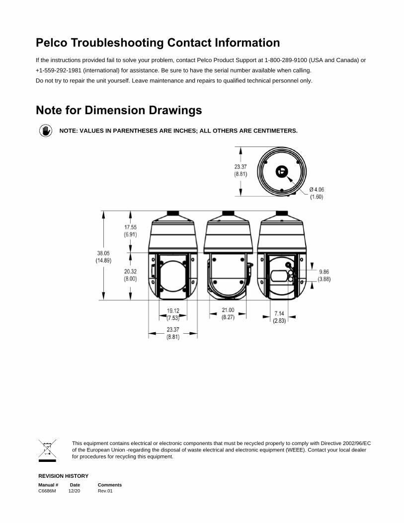
Note for Dimension Drawings
NOTE: VALUES IN PARENTHESES ARE INCHES; ALL OTHERS ARE CENTIMETERS.
REVISION HISTORY
Manual # Date Comments
C6686M 12/20 Rev.01
Pelco, the Pelco logo, and other trademarks associated with Pelco products referred to in this publication are trademarks of Pelco, Inc. or its affiliates. © Copyright 2016, Pelco, Inc. ONVIF and the ONVIF logo are trademarks of ONVIF Inc. All other product names and services are the property of their respective companies. All rights reserved. Product specifications and availability are subject to change without notice.
This equipment contains electrical or electronic components that must be recycled properly to comply with Directive 2002/96/EC
of the European Union -regarding the disposal of waste electrical and electronic equipment (WEEE). Contact your local dealer
for procedures for recycling this equipment.

Pelco, Inc.
625 W. Alluvial
Fresno, California 93711
United States USA & Canada Tel (800) 289-9100 Fax (800) 289-9150
International Tel +1 (559) 292-1981 Fax +1 (559) 348-1120
www.pelco.com www.pelco.com/community