specifications for wtp … · per iec-60034 part-15. (d) 240vac, 415v ac & 220v dc motors :...
TRANSCRIPT
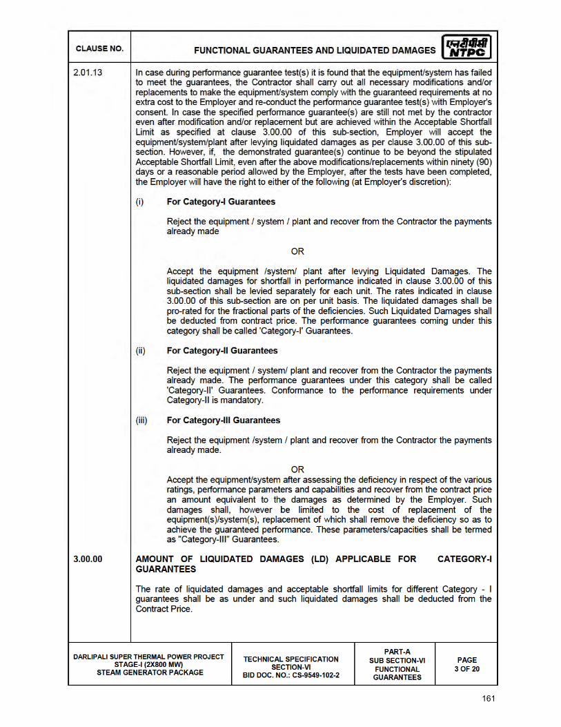
161
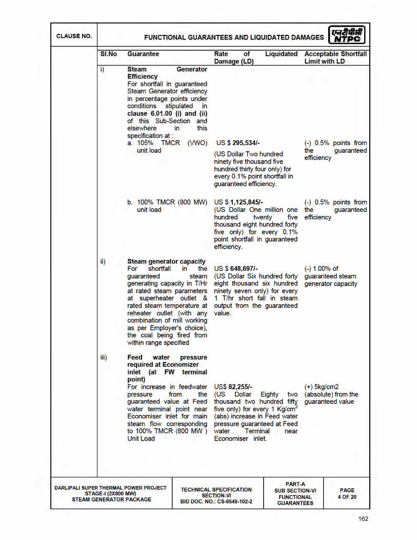
162
163

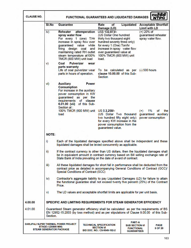
164
165
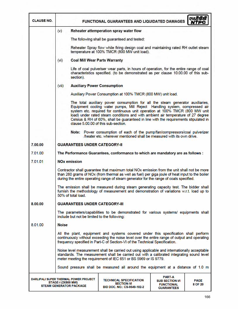
166

167

168

169
BHEL DOCUMENTS NO.: PE-TS-403-160-A001
VOLUME II-B
SECTION -C
2X800MW DARLIPALI STPP, ODISHA REV. NO. 00 DATE:
Page
BHEL – PS - PPEI: NOIDA, SECTOR-16A, U.P. – 201301
TITLE:
TECHNICAL SPECIFICATION FOR MILL REJECT HANDLING SYSTEM
VOLUME – II B
SECTION – C2
SPECIFIC TECHNICAL REQUIREMENTS
ELECTRICAL SPECIFICATION
170
TECHNICAL SPECIFICATION FOR
MILL REJECT SYSTEM
(ELECTRICAL PORTION)
2 X 800 MW DARLIPALI TPP
SPECIFICATION NO.
VOLUME II B
SECTION-C
REV 01
DATE 19.05.2015
PAGE 1 OF 1
SPECIFIC TECHNICAL REQUIREMENTS: ELECTRICAL
1.0 EQUIPMENT & SERVICES TO BE PROVIDED BY BIDDER/ PURCHASER
1.1 Scope for supply, and erection & commissioning of various equipment forming part of electrical system for
this package shall be as per Annexure–I to Section – C [Scope of Work (Electrical)].
1.2 Make of various equipment/ items in the scope of bidder shall be to approval of owner during detailed
engineering stage without any commercial implications.
1.3 Bidder shall furnish all AC as well as DC loads required for the system at different voltage levels (eg. 415V
AC, 240 V AC, 220 V DC etc.) of all types, such as motor feeders, supply feeders in PEM format along with
the offer.
1.4 All electrical equipment shall be suitable for the power supplies, fault levels and climatic conditions indicated
in project information enclosed with the specification.
1.5 All drawings, data sheets, Quality Plan, calculations, test reports, test certificates, etc. shall be submitted
during detailed engineering stage as per formats enclosed. The same shall be subject to approval without
any commercial implications.
1.6 Technical requirements shall be as per specifications listed in Clause 4.1, 4.2 & 4.3 below.
3.0 DOCUMENTS TO BE SUBMITTED ALONG WITH BID
3.1 Bidder shall confirm total compliance to the electrical specification without any deviation from the technical/
quality assurance requirements stipulated. In line with this, the bidder as technical offer shall furnish two
signed and stamped copies of the following:
a) A copy of this sheet “Electrical Equipment Specification for MILL REJECT SYSTEM and sheet
“Electrical Scope between BHEL and Vendor” with bidder’s signature and company stamp.
b) Electrical load requirement in the load data format.
3.2 No technical submittal such as copies of data sheets, drawings, write-up, quality plans, type test certificates,
technical literature, etc, is required during tender stage. Any such submission even if made, shall not be
considered as part of offer.
4.0 LIST OF ENCLOSURES
4.1 Electrical scope between BHEL & vendor (Annexure-I).
4.2 Load data format (Annexure-A).
4.3 Technical spec. for Motors.
4.4 Technical spec. for Cabling
4.5 Technical spec. for LT Power, Control & Instrumentation cables.
4.6 Technical spec. for Junction box, Glands & Lugs.
4.7 Motor datasheet-A
4.8 Datasheet-C (Motors, cables & cabling)
4.9 List of test for motors.
4.10 Quality plans for motors.
171

172
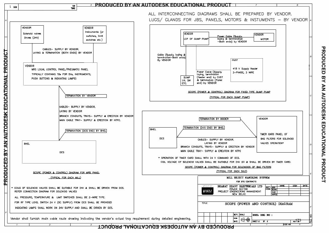
173
CLA
USE
NO
.
SCO
PE O
F SU
PPLY
& S
ERVI
CES
DAR
LIPA
LI S
UPE
R T
HER
MAL
PO
WER
PR
OJE
CT
STAG
E-I (
2X80
0 M
W)
STEA
M T
UR
BIN
E G
ENER
ATO
R P
ACK
AGE
TEC
HN
ICA
L SP
ECIF
ICA
TIO
NS
SEC
TIO
N-V
I PA
RT-
A
SUB
-SEC
TIO
N-B
-1:
ELEC
TRIC
AL
SYST
EM/E
QU
IPM
ENT
PA
GE
4 O
F 4
174
CLAUSE NO. TECHNICAL REQUIREMENTS
DARLIPALI SUPER THERMAL POWER
PROJECT STAGE-I (2X800 MW) STEAM TURBINE GENERATOR PACKAGE
TECHNICAL SPECIFICATIONS
SECTION-VI, PART B
SUB-SECTION-B-02 MOTORS
PAGE 1 OF 9
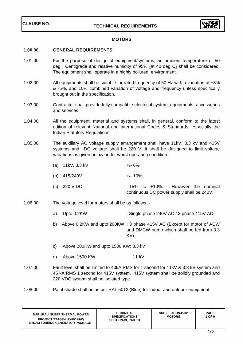
MOTORS
1.00.00 GENERAL REQUIREMENTS
1.01.00 For the purpose of design of equipment/systems, an ambient temperature of 50 deg. Centigrade and relative humidity of 95% (at 40 deg C) shall be considered. The equipment shall operate in a highly polluted environment.
1.02.00 All equipments shall be suitable for rated frequency of 50 Hz with a variation of +3% & -5%, and 10% combined variation of voltage and frequency unless specifically brought out in the specification.
1.03.00 Contractor shall provide fully compatible electrical system, equipments, accessories and services.
1.04.00 All the equipment, material and systems shall, in general, conform to the latest edition of relevant National and international Codes & Standards, especially the Indian Statutory Regulations.
1.05.00 The auxiliary AC voltage supply arrangement shall have 11kV, 3.3 kV and 415V systems and DC voltage shall be 220 V. It shall be designed to limit voltage variations as given below under worst operating condition :
(a) 11kV, 3.3 kV +/- 6%
(b) 415/240V +/- 10%
(c) 220 V DC -15% to +10%. However the nominal continuous DC power supply shall be 240V.
1.06.00 The voltage level for motors shall be as follows :-
a) Upto 0.2KW : Single phase 240V AC / 3 phase 415V AC
b) Above 0.2KW and upto 200KW : 3 phase 415V AC (Except for motor of ACW and DMCW pump which shall be fed from 3.3 KV)
c) Above 200KW and upto 1500 KW: 3.3 kV
d) Above 1500 KW : 11 kV
1.07.00 Fault level shall be limited to 40kA RMS for 1 second for 11kV & 3.3 kV system and 45 kA RMS 1 second for 415V system. 415V system shall be solidly grounded and 220 VDC system shall be isolated type.
1.08.00 Paint shade shall be as per RAL 5012 (Blue) for indoor and outdoor equipment.
175

CLAUSE NO. TECHNICAL REQUIREMENTS
DARLIPALI SUPER THERMAL POWER
PROJECT STAGE-I (2X800 MW) STEAM TURBINE GENERATOR PACKAGE
TECHNICAL SPECIFICATIONS
SECTION-VI, PART B
SUB-SECTION-B-02 MOTORS
PAGE 2 OF 9
1.09.00 The responsibility of coordination with electrical agencies and obtaining all necessary clearances for contractors equipment and systems shall be under the contractor scope.
1.10.00 Degree of Protection
Degree of protection for various enclosures as per IS:4691, IEC60034-05 shall be as follows :-
i) Indoor motors - IP 54
ii) Outdoor motors - IP 55
iii) Cable box-indoor area - IP 54
iv) Cable box-Outdoor area - IP 55
2.00.00 CODES AND STANDARDS
1) Three phase induction motors : IS:325, IEC:60034
2) Single phase AC motors : IS:996, IEC:60034
3) Crane duty motors : IS:3177, IEC:60034
4) DC motors/generators : IS:4722
5) Energy Efficient motors : IS 12615, IEC:60034-30
3.00.00 TYPE
3.01.00 AC Motors:
a) Squirrel cage induction motor suitable for direct-on-line starting.
b) Continuous duty LT motors upto 160 KW Output rating (at 50 deg.C ambient temperature), shall be Premium Efficiency class-IE3, conforming to IS 12615, or IEC:60034-30.
c) Crane duty motors shall be slip ring/ squirrel cage Induction motor as per the requirement.
3.02.00 DC Motors Shunt wound.
4.00.00 RATING
(a) Continuously rated (S1). However, crane motors shall be rated for S4 duty, 40% cyclic duration factor.
(b) Whenever the basis for motor or driven equipment ratings are not specified in the corresponding mechanical specification sub-sections, maximum
176

CLAUSE NO. TECHNICAL REQUIREMENTS
DARLIPALI SUPER THERMAL POWER
PROJECT STAGE-I (2X800 MW) STEAM TURBINE GENERATOR PACKAGE
TECHNICAL SPECIFICATIONS
SECTION-VI, PART B
SUB-SECTION-B-02 MOTORS
PAGE 3 OF 9
continuous motor ratings shall be at least 10% above the maximum load demand of the driven equipment under entire operating range including voltage and frequency variations.
( c) For BFP motors starting MVA shall be restricted to 70 MVA.
5.00.00 TEMPERATURE RISE
Air cooled motors
70 deg. C by resistance method for both thermal class 130(B) & 155(F) insulation.
Water cooled
80 deg. C over inlet cooling water temperature mentioned elsewhere, by resistance method for both thermal class 130(B) & 155(F) insulation.
6.00.00 OPERATIONAL REQUIREMENTS
6.01.00 Starting Time
6.01.01 For motors with starting time upto 20 secs. at minimum permissible voltage during starting, the locked rotor withstand time under hot condition at highest voltage limit shall be at least 2.5 secs. more than starting time.
6.01.02 For motors with starting time more than 20 secs. and upto 45 secs. at minimum permissible voltage during starting, the locked rotor withstand time under hot condition at highest voltage limit shall be at least 5 secs. more than starting time.
6.01.03 For motors with starting time more than 45 secs. at minimum permissible voltage during starting, the locked rotor withstand time under hot condition at highest voltage limit shall be more than starting time by at least 10% of the starting time.
6.01.04 Speed switches mounted on the motor shaft shall be provided in cases where above requirements are not met.
6.02.00 Torque Requirements
6.02.01 Accelerating torque at any speed with the lowest permissible starting voltage shall be at least 10% motor full load torque.
6.02.02 Pull out torque at rated voltage shall not be less than 205% of full load torque. It shall be 275% for crane duty motors.
6.03.00 Starting voltage requirement
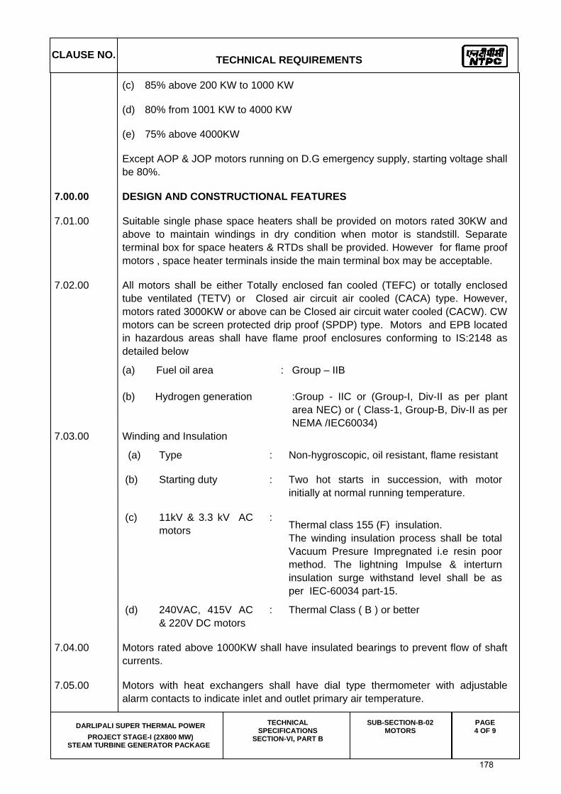
(a) 85% below 110 KW
(b) 80% from 110 KW to 200 KW
177
CLAUSE NO. TECHNICAL REQUIREMENTS
DARLIPALI SUPER THERMAL POWER
PROJECT STAGE-I (2X800 MW) STEAM TURBINE GENERATOR PACKAGE
TECHNICAL SPECIFICATIONS
SECTION-VI, PART B
SUB-SECTION-B-02 MOTORS
PAGE 4 OF 9
(c) 85% above 200 KW to 1000 KW
(d) 80% from 1001 KW to 4000 KW
(e) 75% above 4000KW
Except AOP & JOP motors running on D.G emergency supply, starting voltage shall be 80%.
7.00.00 DESIGN AND CONSTRUCTIONAL FEATURES
7.01.00 Suitable single phase space heaters shall be provided on motors rated 30KW and above to maintain windings in dry condition when motor is standstill. Separate terminal box for space heaters & RTDs shall be provided. However for flame proof motors , space heater terminals inside the main terminal box may be acceptable.
7.02.00 All motors shall be either Totally enclosed fan cooled (TEFC) or totally enclosed tube ventilated (TETV) or Closed air circuit air cooled (CACA) type. However, motors rated 3000KW or above can be Closed air circuit water cooled (CACW). CW motors can be screen protected drip proof (SPDP) type. Motors and EPB located in hazardous areas shall have flame proof enclosures conforming to IS:2148 as detailed below
(a) Fuel oil area : Group – IIB
(b) Hydrogen generation :Group - IIC or (Group-I, Div-II as per plant area NEC) or ( Class-1, Group-B, Div-II as per NEMA /IEC60034)
7.03.00 Winding and Insulation
(a) Type : Non-hygroscopic, oil resistant, flame resistant
(b) Starting duty : Two hot starts in succession, with motor initially at normal running temperature.
(c) 11kV & 3.3 kV AC motors
: Thermal class 155 (F) insulation. The winding insulation process shall be total Vacuum Presure Impregnated i.e resin poor method. The lightning Impulse & interturn insulation surge withstand level shall be as per IEC-60034 part-15.
(d) 240VAC, 415V AC & 220V DC motors
: Thermal Class ( B ) or better
7.04.00 Motors rated above 1000KW shall have insulated bearings to prevent flow of shaft currents.
7.05.00 Motors with heat exchangers shall have dial type thermometer with adjustable alarm contacts to indicate inlet and outlet primary air temperature.
178

CLAUSE NO. TECHNICAL REQUIREMENTS
DARLIPALI SUPER THERMAL POWER
PROJECT STAGE-I (2X800 MW) STEAM TURBINE GENERATOR PACKAGE
TECHNICAL SPECIFICATIONS
SECTION-VI, PART B
SUB-SECTION-B-02 MOTORS
PAGE 5 OF 9
7.06.00 Noise level for all the motors shall be limited to 85dB(A) except for BFP motor for which the maximum limit shall be 90dB(A). Vibration shall be limited within the limits prescribed in IS:12075 / IEC 60034-14 . Motors shall withstand vibrations produced by driven equipment. HT motor bearing housings shall have flat surfaces, in both X and Y directions, suitable for mounting 80mmX80mm vibration pads.
7.07.00 In HT motors, at least four numbers simplex / two numbers duplex platinum resistance type temperature detectors shall be provided in each phase stator winding. Each bearing of HT motor shall be provided with dial type thermometer with adjustable alarm contact and preferably 2 numbers duplex platinum resistance type temperature detectors.
7.08.00 Motor body shall have two earthing points on opposite sides.
7.09.00 11 KV motors shall be offered with Separate Insulated Connector(Elastimould or Equivalent make) as per IEEE 386. The offered elastimould terminations shall be provided with protective cover and trifurcating sleeves. Elastimould termination kit shall be suitable for fault level of 25 KA for 0.17 seconds.
7.10.00 3.3 KV motors shall be offered with dust tight phase separated double walled (metallic as well as insulated barrier) Terminal box. Employer shall provide termination kit for the offered Terminal box. The offered Terminal Box shall be suitable for fault level of 250 MVA for 0.12 sec. Removable gland plates of thickness 3 mm (hot/cold rolled sheet steel) or 4 mm (non magnetic material for single core cables) shall be provided.
7.11.00 The spacing between gland plate & centre of terminal stud shall be as per Table-I.
7.12.00 All motors shall be so designed that maximum inrush currents and locked rotor and pullout torque developed by them at extreme voltage and frequency variations do not endanger the motor and driven equipment.
7.13.00 The motors shall be suitable for bus transfer schemes provided on the 11kV, 3.3 kV /415V systems without any injurious effect on its life.
7.14.00 For motors rated 2000 KW & above, neutral current transformers of PS class shall be provided on each phase in a separate neutral terminal box.
7.15.00 The size and number of cables (for HT and LT motors) to be intimated to the successful bidder during detailed engineering and the contractor shall provide terminal box suitable for the same.
8.00.00 The ratio of locked rotor KVA at rated voltage to rated KW shall not exceed the following (without any further tolerance) except for BFP motor.
(a) Below 110KW : 10.0
(b) From 110 KW & upto 200 KW : 9.0
179
CLAUSE NO. TECHNICAL REQUIREMENTS
DARLIPALI SUPER THERMAL POWER
PROJECT STAGE-I (2X800 MW) STEAM TURBINE GENERATOR PACKAGE
TECHNICAL SPECIFICATIONS
SECTION-VI, PART B
SUB-SECTION-B-02 MOTORS
PAGE 6 OF 9
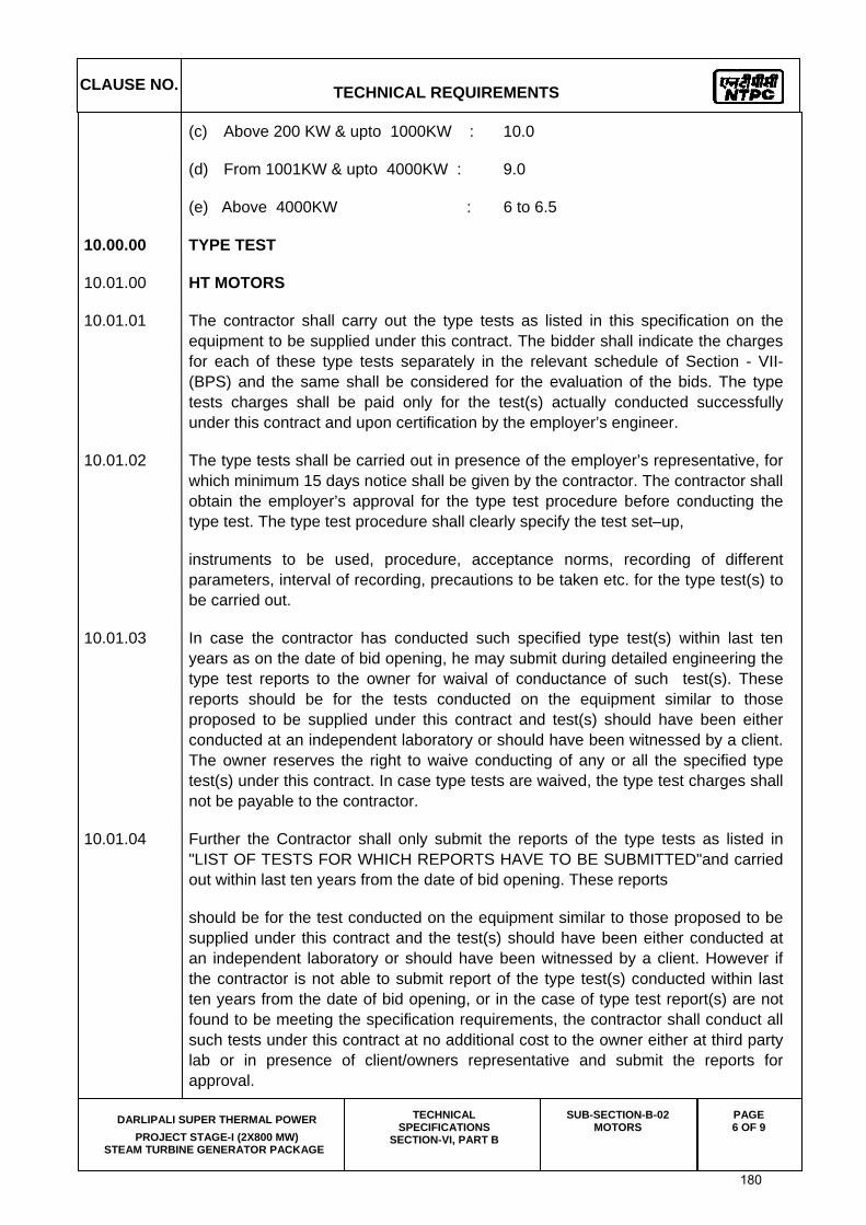
(c) Above 200 KW & upto 1000KW : 10.0
(d) From 1001KW & upto 4000KW : 9.0
(e) Above 4000KW : 6 to 6.5
10.00.00 TYPE TEST
10.01.00 HT MOTORS
10.01.01 The contractor shall carry out the type tests as listed in this specification on the equipment to be supplied under this contract. The bidder shall indicate the charges for each of these type tests separately in the relevant schedule of Section - VII- (BPS) and the same shall be considered for the evaluation of the bids. The type tests charges shall be paid only for the test(s) actually conducted successfully under this contract and upon certification by the employer’s engineer.
10.01.02 The type tests shall be carried out in presence of the employer’s representative, for which minimum 15 days notice shall be given by the contractor. The contractor shall obtain the employer’s approval for the type test procedure before conducting the type test. The type test procedure shall clearly specify the test set–up,
instruments to be used, procedure, acceptance norms, recording of different parameters, interval of recording, precautions to be taken etc. for the type test(s) to be carried out.
10.01.03 In case the contractor has conducted such specified type test(s) within last ten years as on the date of bid opening, he may submit during detailed engineering the type test reports to the owner for waival of conductance of such test(s). These reports should be for the tests conducted on the equipment similar to those proposed to be supplied under this contract and test(s) should have been either conducted at an independent laboratory or should have been witnessed by a client. The owner reserves the right to waive conducting of any or all the specified type test(s) under this contract. In case type tests are waived, the type test charges shall not be payable to the contractor.
10.01.04 Further the Contractor shall only submit the reports of the type tests as listed in "LIST OF TESTS FOR WHICH REPORTS HAVE TO BE SUBMITTED"and carried out within last ten years from the date of bid opening. These reports
should be for the test conducted on the equipment similar to those proposed to be supplied under this contract and the test(s) should have been either conducted at an independent laboratory or should have been witnessed by a client. However if the contractor is not able to submit report of the type test(s) conducted within last ten years from the date of bid opening, or in the case of type test report(s) are not found to be meeting the specification requirements, the contractor shall conduct all such tests under this contract at no additional cost to the owner either at third party lab or in presence of client/owners representative and submit the reports for approval.
180
CLAUSE NO. TECHNICAL REQUIREMENTS
DARLIPALI SUPER THERMAL POWER
PROJECT STAGE-I (2X800 MW) STEAM TURBINE GENERATOR PACKAGE
TECHNICAL SPECIFICATIONS
SECTION-VI, PART B
SUB-SECTION-B-02 MOTORS
PAGE 7 OF 9
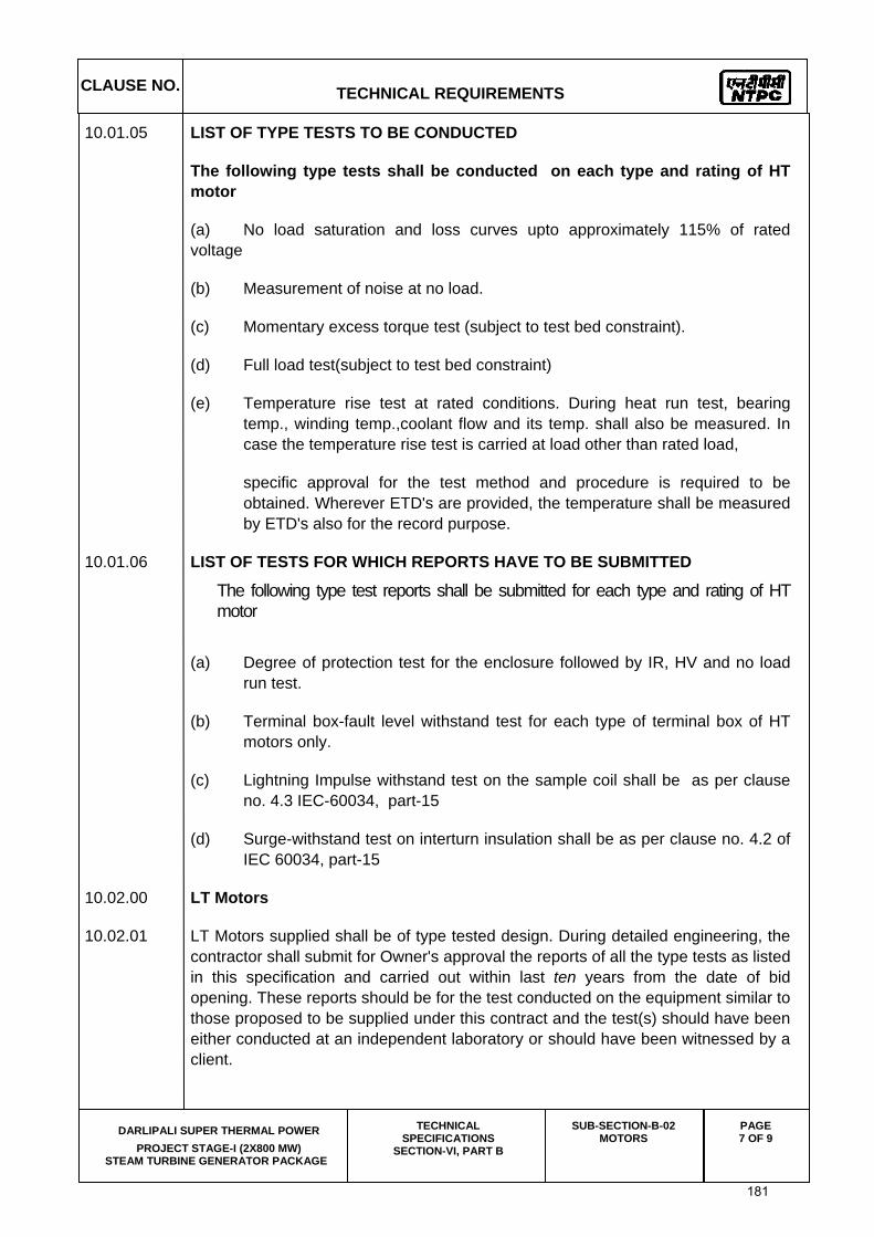
10.01.05 LIST OF TYPE TESTS TO BE CONDUCTED
The following type tests shall be conducted on each type and rating of HT motor
(a) No load saturation and loss curves upto approximately 115% of rated voltage
(b) Measurement of noise at no load.
(c) Momentary excess torque test (subject to test bed constraint).
(d) Full load test(subject to test bed constraint)
(e) Temperature rise test at rated conditions. During heat run test, bearing temp., winding temp.,coolant flow and its temp. shall also be measured. In case the temperature rise test is carried at load other than rated load,
specific approval for the test method and procedure is required to be obtained. Wherever ETD's are provided, the temperature shall be measured by ETD's also for the record purpose.
10.01.06 LIST OF TESTS FOR WHICH REPORTS HAVE TO BE SUBMITTED
The following type test reports shall be submitted for each type and rating of HT motor
(a) Degree of protection test for the enclosure followed by IR, HV and no load run test.
(b) Terminal box-fault level withstand test for each type of terminal box of HT motors only.
(c) Lightning Impulse withstand test on the sample coil shall be as per clause no. 4.3 IEC-60034, part-15
(d) Surge-withstand test on interturn insulation shall be as per clause no. 4.2 of IEC 60034, part-15
10.02.00 LT Motors
10.02.01 LT Motors supplied shall be of type tested design. During detailed engineering, the contractor shall submit for Owner's approval the reports of all the type tests as listed in this specification and carried out within last ten years from the date of bid opening. These reports should be for the test conducted on the equipment similar to those proposed to be supplied under this contract and the test(s) should have been either conducted at an independent laboratory or should have been witnessed by a client.
181
CLAUSE NO. TECHNICAL REQUIREMENTS
DARLIPALI SUPER THERMAL POWER
PROJECT STAGE-I (2X800 MW) STEAM TURBINE GENERATOR PACKAGE
TECHNICAL SPECIFICATIONS
SECTION-VI, PART B
SUB-SECTION-B-02 MOTORS
PAGE 8 OF 9
10.02.02 However if the contractor is not able to submit report of the type test(s) conducted within last ten years from the date of bid opening, or in the case of type test report(s) are not found to be meeting the specification requirements, the contractor shall conduct all such tests under this contract at no additional cost to the owner either at third party lab or in presence of client/owners representative and submit the reports for approval.
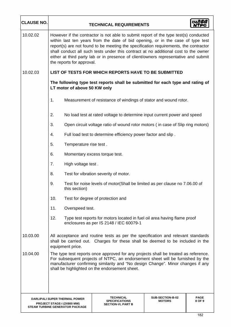
10.02.03 LIST OF TESTS FOR WHICH REPORTS HAVE TO BE SUBMITTED
The following type test reports shall be submitted for each type and rating of LT motor of above 50 KW only 1. Measurement of resistance of windings of stator and wound rotor. 2. No load test at rated voltage to determine input current power and speed
3. Open circuit voltage ratio of wound rotor motors ( in case of Slip ring motors) 4. Full load test to determine efficiency power factor and slip . 5. Temperature rise test . 6. Momentary excess torque test. 7. High voltage test .
8. Test for vibration severity of motor. 9. Test for noise levels of motor(Shall be limited as per clause no 7.06.00 of
this section) 10. Test for degree of protection and 11. Overspeed test. 12. Type test reports for motors located in fuel oil area having flame proof
enclosures as per IS 2148 / IEC 60079-1
10.03.00 All acceptance and routine tests as per the specification and relevant standards shall be carried out. Charges for these shall be deemed to be included in the equipment price.
10.04.00 The type test reports once approved for any projects shall be treated as reference. For subsequent projects of NTPC, an endorsement sheet will be furnished by the manufacturer confirming similarity and “No design Change”. Minor changes if any shall be highlighted on the endorsement sheet.
182
CLAUSE NO. TECHNICAL REQUIREMENTS
DARLIPALI SUPER THERMAL POWER
PROJECT STAGE-I (2X800 MW) STEAM TURBINE GENERATOR PACKAGE
TECHNICAL SPECIFICATIONS
SECTION-VI, PART B
SUB-SECTION-B-02 MOTORS
PAGE 9 OF 9
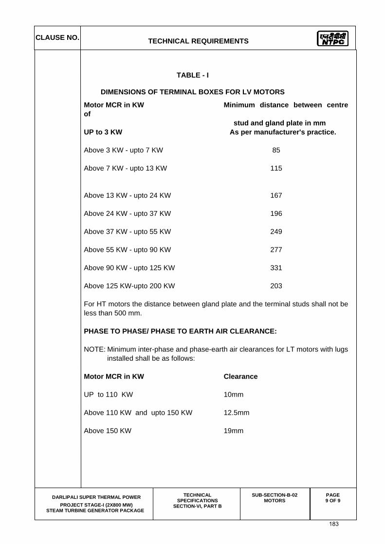
TABLE - I
DIMENSIONS OF TERMINAL BOXES FOR LV MOTORS
Motor MCR in KW Minimum distance between centre of
stud and gland plate in mm UP to 3 KW As per manufacturer's practice. Above 3 KW - upto 7 KW 85 Above 7 KW - upto 13 KW 115 Above 13 KW - upto 24 KW 167 Above 24 KW - upto 37 KW 196 Above 37 KW - upto 55 KW 249 Above 55 KW - upto 90 KW 277 Above 90 KW - upto 125 KW 331 Above 125 KW-upto 200 KW 203 For HT motors the distance between gland plate and the terminal studs shall not be
less than 500 mm. PHASE TO PHASE/ PHASE TO EARTH AIR CLEARANCE: NOTE: Minimum inter-phase and phase-earth air clearances for LT motors with lugs
installed shall be as follows: Motor MCR in KW Clearance UP to 110 KW 10mm Above 110 KW and upto 150 KW 12.5mm Above 150 KW 19mm
183
CLAUSE NO.
TECHNICAL REQUIREMENTS
DARLIPALI SUPER THERMAL POWER
PROJECT STAGE-I (2X800 MW) STEAM TURBINE GENERATOR PACKAGE
TECHNICAL SPECIFICATION SECTION - VI
PART-B
SUB-SECTION-B-5 CABLING EARTHING &
LIGHTNING PROTECTION
PAGE 1 OF 1
CABLING, EARTHING & LIGHTNING PROTECTION
1.00.00 CODES AND STANDARDS: 1.01.00 All standards, specifications and codes of practice referred to herein shall be
the latest editions including all applicable official amendments and revisions. In case of conflict between this specification and those (IS codes, standards, etc.) referred to herein, the former shall prevail. All work shall be carried out as per the following standards/ codes as applicable.
IS:2309, IEEE:142, IEEE-80, IS:1255, IS:3043, DIN 46235. 2.00.00 REQUIREMENTS 2.01.00 The complete cable support system shall be supplied and installed for the entire
work is in the bidder's scope. The system shall enable proper laying of all power, control, instrumentation and telephone cables, and shall provide necessary mechanical protection, ventilation and segregation for them as per latest engineering practices and cable manufacturers' recommendation .The cable installation shall be carried out as per IS:1255. All hardware and anchoring arrangement shall be included. All steel members shall be hot dip galvanized.
184

CLAUSE NO.
TECHNICAL REQUIREMENTS
DARLIPALI SUPER THERMAL POWER PROJECT STAGE-I (2X800 MW)
STEAM TURBINE GENERATOR PACKAGE
TECHNICAL SPECIFICATIONS SECTION-VI, PART-B
SUB-SECTION-B-3 LT POWER CABLES
PAGE 1 OF 7
LT POWER CABLES
1.00.00 CODES & STANDARDS
1.01.00 All standards, specifications and codes of practice referred to herein shall be the latest editions including all applicable official amendments and revisions. In case of conflict between this specification and those (IS : codes, standards, etc.) referred to herein, the former shall prevail. All the cables shall conform to the requirements of the following standards and codes:
IS :1554 - I PVC insulated (heavy duty) electric cables for working voltages upto and including 1100V.
IS : 3961 Recommended current ratings for cables
IS : 3975 Low carbon galvanised steel wires, formed wires and tapes for armouring of cables.
IS : 5831 PVC insulation and sheath of electrical cables.
IS:7098 (Part -I) Cross linked polyethylene insulated PVC sheathed cables for working voltages upto and including 1100V.
IS : 8130 Conductors for insulated electrical cables and flexible cords.
IS : 10418 Specification for drums for electric cables.
IS : 10810 Methods of tests for cables.
ASTM-D -2843 Standard test method for density of smoke from the burning or decomposition of plastics.
IEC-754 (Part-I)
Tests on gases evolved during combustion of electric cables.
IEC-332 Tests on electric cables under fire conditions. Part-3: Tests on bunched wires or cables (Category-B).
185

CLAUSE NO.
TECHNICAL REQUIREMENTS
DARLIPALI SUPER THERMAL POWER PROJECT STAGE-I (2X800 MW)
STEAM TURBINE GENERATOR PACKAGE
TECHNICAL SPECIFICATIONS SECTION-VI, PART-B
SUB-SECTION-B-3 LT POWER CABLES
PAGE 2 OF 7
2.00.00 TECHNICAL REQUIREMENTS
2.01.00 The cables shall be suitable for laying on racks, in ducts, trenches, conduits and under ground buried installation with chances of flooding by water.
2.02.00 Cables shall be flame retardant, low smoke (FRLS) type designed to withstand all mechanical, electrical and thermal stresses developed under steady state and transient operating conditions as specified elsewhere in this specification.
2.03.00 Aluminium conductor used in power cables shall have tensile strength of more than 100 N/ sq.mm. Conductors shall be stranded.
2.04.00 XLPE insulation shall be suitable for a continuous conductor temperature of 90 deg. C and short circuit conductor temperature of 250 deg C. PVC insulation shall be suitable for continuous conductor temperature of 70 deg C and short circuit conductor temperature of 160 deg. C.
2.05.00 The cable cores shall be laid up with fillers between the cores wherever necessary. It shall not stick to insulation and inner sheath. All the cables, other than single core unarmoured cables, shall have distinct extruded PVC inner sheath of black colour as per IS : 5831.
2.06.00 For single core armoured cables, armouring shall be of aluminium wires/ formed wires. For multicore armoured cables, armouring shall be of galvanised steel as follows :
Calculated nominal dia. of cable under armour
Size and Type of armour
Upto 13 mm
1.4mm dia GS wire
Above 13 & upto 25mm 0.8 mm thick GS formed wire / 1.6 mm dia GS wire
Above 25 & upto 40 mm 0.8mm thick GS formed wire / 2.0mm dia GS wire
Above 40 & upto 55mm 1.4 mm thick GS formed wire /2.5mm dia GS wire
Above 55 & upto 70 mm 1.4mm thick GS formed wire / 3.15mm dia GS wire
Above 70mm 1.4 mm thick GS formed wire / 4.0 mm dia GS wire
2.06.01 The aluminium used for armouring shall be of H4 grade as per IS: 8130 with maximum resistivity of 0.028264 ohm mm2 per meter at 20 deg C. The sizes of aluminium armouring shall be same as indicated above for galvanized steel.
2.06.02 The gap between armour wires / formed wires shall not exceed one armour wire / formed wire space and there shall be no cross over / over-riding of armour wire / formed wire. The minimum area of coverage of armouring shall be 90%. The breaking load of armour joint shall not be less than 95% of that of armour wire /
186
CLAUSE NO.
TECHNICAL REQUIREMENTS
DARLIPALI SUPER THERMAL POWER PROJECT STAGE-I (2X800 MW)
STEAM TURBINE GENERATOR PACKAGE
TECHNICAL SPECIFICATIONS SECTION-VI, PART-B
SUB-SECTION-B-3 LT POWER CABLES
PAGE 3 OF 7
formed wire. Zinc rich paint shall be applied on armour joint surface of G.S.wire/ formed wire.
2.07.00 Outer sheath shall be of PVC as per IS: 5831 & black in colour. In addition to meeting all the requirements of Indian standards referred to, outer sheath of all the cables shall have the following FRLS properties.
(a.) Oxygen index of min. 29 (as per IS 10810 Part-58).
(b.) Acid gas emission of max. 20% (as per IEC-754-I).
(c.) Smoke density rating shall not be more than 60 % (as per ASTMD-2843).
2.08.00 Cores of the cables shall be identified by colouring of insulation. Following colour scheme shall be adopted:
1 core - Red, Black, Yellow or Blue
2 core - Red & Black
3 core - Red, Yellow & Blue
4 core - Red, Yellow, Blue and Black
2.09.00 For reduced neutral conductors, the core shall be black.
2.10.00 In addition to manufacturer's identification on cables as per IS, following marking shall also be provided over outer sheath.
(a.) Cable size and voltage grade - To be embossed
(b.) Word 'FRLS' at every 5 metre - To be embossed
(c.) Sequential marking of length of the cable in metres at every one metre -To be embossed / printed
The embossing shall be progressive, automatic, in line and marking shall be legible and indelible.
2.11.00 All cables shall meet the fire resistance requirement as per Category-B of IEC 332 Part-3.
2.12.00 Allowable tolerances on the overall diameter of the cables shall be +\-2 mm maximum, over the declared value in the technical data sheets.
2.13.00 In plant repairs to the cables shall not be accepted. Pimples, fish eye, blow holes etc. are not acceptable.
3.00.00 Cable selection & sizing
3.01.00 LT Power cables shall be sized based on the following considerations:
187
CLAUSE NO.
TECHNICAL REQUIREMENTS
DARLIPALI SUPER THERMAL POWER PROJECT STAGE-I (2X800 MW)
STEAM TURBINE GENERATOR PACKAGE
TECHNICAL SPECIFICATIONS SECTION-VI, PART-B
SUB-SECTION-B-3 LT POWER CABLES
PAGE 4 OF 7
(a) Rated current of the equipment
(b) The voltage drop in the cable, during motor starting condition, shall be limited to 10% and during full load running condition, shall be limited to 3% of the rated voltage
(c) Short circuit withstand capability
This will depend on the feeder type. For a fuse protected circuit, cable should be sized to withstand the let out energy of the fuse.For breaker controlled feeder, cable shall be capable of withstanding the system fault current level for total breaker tripping time inclusive of relay pickup time.
(d) The minimum conductor size shall be 6 sqmm for aluminium conductor cables and 2.5 sqmm for copper conductor cables. The constructional details of copper conductor cables shall be same as indicated for copper control cable.
302.00 Derating Factors
Derating factors for various conditions of installations including the following shall be considered while selecting the cable sizes:
a) Variation in ambient temperature for cables laid in air
b) Grouping of cables
c) Variation in ground temperature and soil resistivity for buried cables.
3.03.00 Cable lengths shall be considered in such a way that straight through cable joints are avoided.
3.04.00 Cables shall be armoured type if laid in switchyard area or directly buried.
3.05.00 All LT power cables of sizes more than 120 sq.mm. shall be XLPE insulated and preferable sizes are 1Cx150, 1Cx300, 1Cx630, 3Cx150 & 3Cx240 sq.mm.
4.00.00 CONSTRUCTIONAL FEATURES
(a.) 1.1 KV grade XLPE power cables shall have compacted aluminium conductor, XLPE insulated, PVC inner sheathed (as applicable), armoured/ unarmoured, FRLS PVC outer sheathed conforming to IS:7098. (Part-I).
(b.) 1.1KV grade PVC power cables shall have aluminium conductor (compacted type for sizes above 10 sq.mm), PVC Insulated, PVC inner sheathed, armoured/ unarmoured, FRLS PVC outer sheathed conforming to IS:1554 (Part-I).
188
CLAUSE NO.
TECHNICAL REQUIREMENTS
DARLIPALI SUPER THERMAL POWER PROJECT STAGE-I (2X800 MW)
STEAM TURBINE GENERATOR PACKAGE
TECHNICAL SPECIFICATIONS SECTION-VI, PART-B
SUB-SECTION-B-3 LT POWER CABLES
PAGE 5 OF 7
5.00.00 CABLE DRUMS
(a) Cables shall be supplied in non returnable wooden or steel drums of heavy construction. The surface of the drum and the outer most cable layer shall be covered with water proof cover. Both the ends of the cables shall be properly sealed with heat shrinkable PVC/ rubber caps secured by 'U' nails so as to eliminate ingress of water during transportation, storage and erection. Wood preservative anti-termite treatment shall be applied to the entire drum. Wooden drums shall comply with IS: 10418.
(b) Each drum shall carry manufacturer's name, purchaser’s name, address and contract number, item number and type, size and length of cable and net gross weight stencilled on both sides of the drum. A tag containing same information shall be attached to the leading end of the cable. An arrow and suitable accompanying wording shall be marked on one end of the reel indicating the direction in which it should be rolled.
5.00.00 TYPE TESTS
5.01.00 General
All equipments to be supplied shall be of type tested design. During detailed engineering, the contractor shall submit for Owner’s approval the reports of all the type tests as listed in this specification and carried out within last ten years from the date of bid opening. These reports should be for the test conducted on the equipment similar to those proposed to be supplied under this contract and the test(s) should have been either conducted at an independent laboratory or should have been witnessed by a client.
However if the contractor is not able to submit report of the type test(s) conducted within last ten years from the date of bid opening, or in the case of type test report(s) are not found to be meeting the specification requirements, the contractor shall conduct all such tests under this contract at no additional cost to the owner either at third party lab or in presence of client /owners representative and submit the reports for approval.
All acceptance and routine tests as per the specification and relevant standards shall be carried out. Charges for these shall be deemed to be included in the equipment price.
The type test reports once approved for any projects shall be treated as reference. For subsequent projects of NTPC, an endorsement sheet will be furnished by the manufacturer confirming similarity and “No design Change”. Minor changes if any shall be highlighted on the endorsement sheet.
5.02.00 Type Tests
5.02.01 The reports for the following type tests shall be submitted for one size each of LT XLPE and LT PVC Power cables. Size shall be decided by the employer during detailed engineering :
S.No. Type test Remarks
189
CLAUSE NO.
TECHNICAL REQUIREMENTS
DARLIPALI SUPER THERMAL POWER PROJECT STAGE-I (2X800 MW)
STEAM TURBINE GENERATOR PACKAGE
TECHNICAL SPECIFICATIONS SECTION-VI, PART-B
SUB-SECTION-B-3 LT POWER CABLES
PAGE 6 OF 7
For Conductor 1. Resistance test
2. Tensile test For circular non-compacted
conductors only
3. Wrapping test For circular non-compacted
only
For Armour Wires/ Formed Wires
4. Measurement of Dimensions
5. Tensile Test
6. Elongation test
7. Torsion test For round wires only
8. Wrapping test For aluminium wires /
formed wires only.
9. Resistance test
10(a) Mass of zinc coating test For GS Formed wires/wires
only
10(b) Uniformity of zinc coating For GS Formed wires /wires
only
11. Adhesion test For GS Formed wires/wires
only
For PVC/XLPE insulation & PVC Sheath
12. Test for thickness
13. Tensile strength & elongation
tests
before ageing and after ageing
14. Ageing in air oven
15. Loss of mass test For PVC insulation and sheath
only
16. Hot deformation test For PVC insulation and sheath
only
17. Heat shock test For PVC insulation and sheath
only
18. Shrinkage test
19. Thermal stability test For PVC insulation and sheath
only
190

CLAUSE NO.
TECHNICAL REQUIREMENTS
DARLIPALI SUPER THERMAL POWER PROJECT STAGE-I (2X800 MW)
STEAM TURBINE GENERATOR PACKAGE
TECHNICAL SPECIFICATIONS SECTION-VI, PART-B
SUB-SECTION-B-3 LT POWER CABLES
PAGE 7 OF 7
20. Hot set test For XLPE insulation only
21. Water absorption test For XLPE insulation only
22. Oxygen index test For outer sheath only
23. Smoke density test For outer sheath only
24. Acid gas generation test For outer sheath only
For completed cables
25. Insulation resistance test
(Volume resistivity method)
26. High voltage test
27. Flammability test as per IEC-332 Part-3 (Category-B)
5.02.02 Acceptance Tests (as per QA table) 5.02.03 Routine Tests (as per QA table)
191
CLAUSE NO.
TECHNICAL REQUIREMENTS
DARLIPALI SUPER THERMAL POWER
PROJECT STAGE-I (2X800 MW) STEAM TURBINE GENERATOR PACKAGE
TECHNICAL SPECIFICATIONS SECTION-VI, PART-B
SUB-SECTION-B-4 LT CONTROL CABLES PAGE 1 OF 7
LT CONTROL CABLES
1.00.00 CODES & STANDARDS 1.01.00 All standards, specifications and codes of practice referred to herein shall be the
latest editions including all applicable official amendments and revisions. In case of conflict between this specification and those (IS : codes, standards, etc.) referred to herein, the former shall prevail. All the cables shall conform to the requirements of the following standards and codes :
IS :1554 - I PVC insulated (heavy duty) electric cables for working
voltages upto and including 1100V. IS : 3961 Recommended current ratings for cables IS : 3975 Low carbon galvanised steel wires, formed wire and
tapes for armouring of cables. IS : 4905 Methods for random sampling. IS : 5831 PVC insulation and sheath of electrical cables. IS : 8130 Conductors for insulated electrical cables and flexible
cords. IS : 10418 Specification for drums for electric cables. IS : 10810 Methods of tests for cables. ASTM-D -2843 Standard test method for density of smoke from the
burning or decomposition of plastics. IEC-754 (Part-I) Test on gases evolved during combustion of electric
cables. IEC -332 Tests on Electric cables under fire conditions Part-3 : Tests on bunched wires or cables (category -
B) 2.00.00 TECHNICAL REQUIREMENTS 2.01.00 The cables shall be suitable for laying on racks, in ducts, trenches, conduits and
under ground burried installation with chances of flooding by water.
192

CLAUSE NO.
TECHNICAL REQUIREMENTS
DARLIPALI SUPER THERMAL POWER
PROJECT STAGE-I (2X800 MW) STEAM TURBINE GENERATOR PACKAGE
TECHNICAL SPECIFICATIONS SECTION-VI, PART-B
SUB-SECTION-B-4 LT CONTROL CABLES PAGE 2 OF 7
2.02.00 Cables shall be flame retardant, low smoke (FRLS) type designed to withstand all mechanical, electrical and thermal stresses develop under steady state and transient operating conditions as specified elsewhere in this specification.
2.03.00 Conductor of control cables shall be made of stranded, plain annealed copper. 2.04.00 PVC insulation shall be suitable for continuous conductor temperature of 70 deg C
and short circuit conductor temperature of 160 deg. C. 2.05.00 The cable cores shall be laid up with fillers between the cores wherever necessary.
It shall not stick to insulation and inner sheath. All the cables, other than single core unarmoured cables, shall have distinct extruded PVC inner sheath of black colour as per IS : 5831.
2.06.00 For multicore armoured cables, the armouring shall be of galvanised steel as
follows :- Calculated nominal dia Size and Type of armour of cable under armour 1) Upto 13 mm 1.4mm dia GS wire 2) Above 13 upto 25 mm 0.8 mm thick GS formed wire / 1.6 mm dia GS wire 3) Above 25 upto 40 mm 0.8mm thick GS formed wire / 2.0mm dia GS wire 4) Above 40 upto 55mm 1.4 mm thick GS formed wire/ 2.5mm dia GS wire 5) Above 55 upto 70 mm 1.4mm thick GS formed wire / 3.15mm dia GS wire 6) Above 70mm 1.4 mm thick GS formed wire / 4.0 mm dia GS wire The gap between armour wire / formed wire shall not exceed one armour wire /
formed wire space and there shall be no cross over / over-riding of armour wire / formed wire. The minimum area of coverage of armouring shall be 90%. The breaking load of armour joint shall not be less than 95% of that of armour wire / formed wire. Zinc rich paint shall be applied on armour joint surface.
2.07.00 Outer sheath shall be of PVC as per IS: 5831 and grey in colour . In addition to
meeting all the requirements of Indian standards referred to, outer sheath of all the cables shall have the following FRLS properties.
193

CLAUSE NO.
TECHNICAL REQUIREMENTS
DARLIPALI SUPER THERMAL POWER
PROJECT STAGE-I (2X800 MW) STEAM TURBINE GENERATOR PACKAGE
TECHNICAL SPECIFICATIONS SECTION-VI, PART-B
SUB-SECTION-B-4 LT CONTROL CABLES PAGE 3 OF 7
(a) Oxygen index of min. 29 (As per IS:10810 (part-58)) (b) Acid gas emission of max. 20% (As per IEC-754-I). (c) Smoke density rating shall not be more than 60% during Smoke Density Test
as per ASTMD-2843. 2.08.00 Cores of the cables of upto 5 cores shall be identified by colouring of insulation. Following colour scheme shall be adopted. 1 core - Red, Black, Yellow or Blue 2 core - Red & Black 3 core - Red, Yellow & Blue 4 core - Red, Yellow, Blue and Black 5 core - Red, Yellow, Blue, Black and Grey 2.09.00 For cables having more than 5 cores, core identification shall be done by numbering
the insulation of cores sequentially, starting by number 1 in the inner layer (e.g. say for 10 core cable, core numbering shall be from 1 to 10). The number shall be printed in Hindu-Arabic numerals on the outer surfaces of the cores. All the numbers shall be of the same colour, which shall contrast with the colour of insulation. The colour of insulation for all the cores shall be grey only. The numerals shall be legible and indelible. The numbers shall be repeated at regular intervals along the core, consecutive numbers being inverted in relation to each other. When the number is a single numeral, a dash shall be placed under neath it. If the number consists of two numerals, these shall be disposed one below the other and a dash placed below the lower numeral. The spacing between consecutive numbers shall not exceed 50 mm.
2.10.00 In addition to manufacturer's identification on cables as per IS, following marking
shall also be provided over outer sheath : (a) Cable size and voltage grade - To be embossed (b) Word 'FRLS' at every 5 metre - To be embossed (c) Sequential marking of length of the cable in metres at every one metre. - To be embossed / printed. The embossing / printing shall be progressive, automatic, in line and marking shall
be legible and indelible. For EPR cables identification shall be printed on outer sheath.
194
CLAUSE NO.
TECHNICAL REQUIREMENTS
DARLIPALI SUPER THERMAL POWER
PROJECT STAGE-I (2X800 MW) STEAM TURBINE GENERATOR PACKAGE
TECHNICAL SPECIFICATIONS SECTION-VI, PART-B
SUB-SECTION-B-4 LT CONTROL CABLES PAGE 4 OF 7
2.11.00 All cables shall meet the fire resistance requirement as per Category-B of IEC 332
Part -3. 2.12.00 Allowable tolerances on the overall diameter of the cables shall be +\-2 mm
maximum over the declared value in the technical data sheets. 2.13.00 In plant repairs to the cables shall not be accepted. Pimples, fish eye, blow holes
etc. are not acceptable. 2.14.00 Cable selection & sizing 2.14.01 Control cables shall be sized based on the following considerations: (a) The minimum conductor cross-section shall be 1.5 sq.mm. (b) The minimum number of spare cores in control cables shall be as follows: No. of cores in cable Min. No. of spare cores 2C, 3C NIL 5C 1 7C-12C 2 14C & above 3 2.14.03 Cable lengths shall be considered in such a way that straight through cable joints
are avoided. 2.14.04 Cables shall be armoured type if laid in switchyard area or directly buried. 3.00.00 CONSTRUCTIONAL FEATURES 3.01.00 1.1 KV Grade Control Cables Control Cables shall have stranded copper conductor and shall be multicore PVC
insulated, PVC inner-sheathed, armoured / unarmoured, FRLS PVC outer-sheathed conforming to IS:1554. (Part-I).
3.02.00 Cable Drums (a) Cables shall be supplied in non returnable wooden or steel drums of heavy
construction. The surface of the drum and the outer most cable layer shall be covered with water proof cover. Both the ends of the cables shall be properly sealed with heat shrinkable PVC/ rubber caps secured by 'U' nails so as to
195
CLAUSE NO.
TECHNICAL REQUIREMENTS
DARLIPALI SUPER THERMAL POWER
PROJECT STAGE-I (2X800 MW) STEAM TURBINE GENERATOR PACKAGE
TECHNICAL SPECIFICATIONS SECTION-VI, PART-B
SUB-SECTION-B-4 LT CONTROL CABLES PAGE 5 OF 7
eliminate ingress of water during transportation, storage and erection. Wood preservative anti-termite treatment shall be applied to the entire drum. Wooden drums shall comply with IS : 10418.
(b) Each drum shall carry manufacturer's name, purchaser's name, address and
contract number, item number and type, size and length of cable and net gross weight stencilled on both the sides of the drum. A tag containing same information shall be attached to the leading end of the cable. An arrow and suitable accompanying wording shall be marked on one end of the reel indicating the direction in which it should be rolled.
4.00.00 TESTS 4.01.00 GENERAL
All equipments to be supplied shall be of type tested design. During detailed engineering, the contractor shall submit for Owner’s approval the reports of all the type tests as listed in this specification and carried out within last ten years from the date of bid opening. These reports should be for the test conducted on the equipment similar to those proposed to be supplied under this contract and the test(s) should have been either conducted at an independent laboratory or should have been witnessed by a client.
However if the contractor is not able to submit report of the type test(s) conducted within last ten years from the date of bid opening, or in the case of type test report(s) are not found to be meeting the specification requirements, the contractor shall conduct all such tests under this contract at no additional cost to the owner either at third party lab or in presence of client /owners representative and submit the reports for approval.
All acceptance and routine tests as per the specification and relevant standards shall be carried out. Charges for these shall be deemed to be included in the equipment price.
The type test reports once approved for any projects shall be treated as reference. For subsequent projects of NTPC, an endorsement sheet will be furnished by the manufacturer confirming similarity and “No design Change”. Minor changes if any shall be highlighted on the endorsement sheet.
4.02.00 TYPE TESTS: 4.02.01 The Type tests reports for the following shall be submitted for one size of LT control cable :
196
CLAUSE NO.
TECHNICAL REQUIREMENTS
DARLIPALI SUPER THERMAL POWER
PROJECT STAGE-I (2X800 MW) STEAM TURBINE GENERATOR PACKAGE
TECHNICAL SPECIFICATIONS SECTION-VI, PART-B
SUB-SECTION-B-4 LT CONTROL CABLES PAGE 6 OF 7
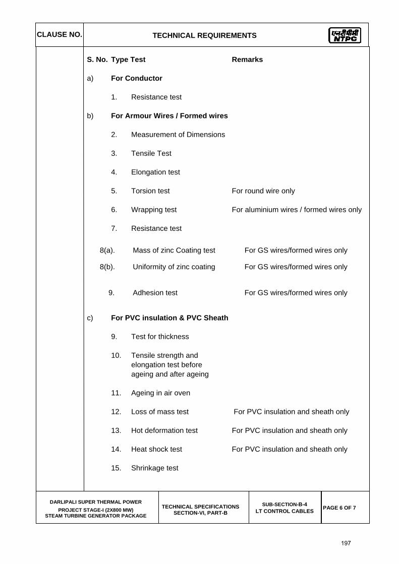
S. No. Type Test Remarks a) For Conductor 1. Resistance test b) For Armour Wires / Formed wires 2. Measurement of Dimensions 3. Tensile Test 4. Elongation test 5. Torsion test For round wire only 6. Wrapping test For aluminium wires / formed wires only 7. Resistance test
8(a). Mass of zinc Coating test For GS wires/formed wires only
8(b). Uniformity of zinc coating For GS wires/formed wires only
9. Adhesion test For GS wires/formed wires only
c) For PVC insulation & PVC Sheath 9. Test for thickness 10. Tensile strength and elongation test before ageing and after ageing 11. Ageing in air oven 12. Loss of mass test For PVC insulation and sheath only 13. Hot deformation test For PVC insulation and sheath only 14. Heat shock test For PVC insulation and sheath only 15. Shrinkage test
197

CLAUSE NO.
TECHNICAL REQUIREMENTS
DARLIPALI SUPER THERMAL POWER
PROJECT STAGE-I (2X800 MW) STEAM TURBINE GENERATOR PACKAGE
TECHNICAL SPECIFICATIONS SECTION-VI, PART-B
SUB-SECTION-B-4 LT CONTROL CABLES PAGE 7 OF 7
16. Thermal stability test For PVC insulation and sheath only 17. Oxygen index test For outer sheath only 18. Smoke density test For outer sheath only 19. Acid gas generation test For outer sheath only d) For completed cables 20. Insulation resistance test (Volume resistivity method) 21. High voltage test 23. Flammability test as per IEC - 332 Part-3 (Category-B) 4.02.02 Acceptance Tests (as per QA table) 4.03.00 Routine Tests (as per QA table)
198
CLAUSE NO.
TECHNICAL REQUIREMENTS
DARLIPALI SUPER THERMAL POWER PROJECT
STAGE-I (2X800 MW) STEAM TURBINE GENERATOR PACKAGE
TECHNICAL SPECIFICATIONS SECTION-VI
PART-B
SUB-SECTION-IIIC-07 INSTRUMENTATION AND POWER SUPPLY CABLE
PAGE 2 OF 19
INSTRUMENTATION AND POWER SUPPLY CABLE
1.00.00 INSTRUMENTATION CABLE, POWER SUPPLY CABLE, INTERNAL WIRING AND ELECTRICAL FIELD CONSTRUCTION MATERIAL
1.01.00 General Requirements
1.01.01 All cables including special cables, internal wiring and electrical field construction material shall conform to this specification, Employer approved detail engineering drawings & documents and the latest edition of the relevant standards & guidelines. The Bidder shall furnish all material and services required for the completeness of the work identified in his scope as per this specification.
1.01.02 The Contractor shall supply, erect, terminate and test all instrumentation cables for control and instrumentation equipment/devices/systems included under Contractor's scope as illustrated in the enclosed Drg. No. 0000-110-POI-A-021 and ensuring completeness of the control system.
1.01.03 Any other application where it is felt that instrumentation cables are required due to system/operating condition requirements, are also to be provided by Contractor.
1.01.04 Other type of cables like fiber optic/co-axial cables for system bus, cables for connection of peripherals etc. (under Contractor's scope) are also to be furnished by the Contractor.
1.01.05 Contractor shall supply all cable erection and laying hardware from the main trunk routes like branch cable trays/sub-trays, supports, flexible conduits, cable glands, lugs, pull boxes etc. on as required basis for all the systems covered under this specification.
1.01.06 Wherever the quantity has been defined as on as required basis, the same are to be furnished by contractor on as required basis within his quoted lump sump price without any further cost implication to the Employer.
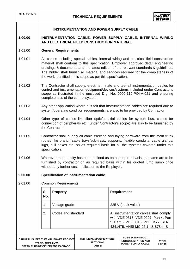
2.00.00 Specification of Instrumentation cable
2.01.00 Common Requirements
S. No.
Property Requirement
1 Voltage grade 225 V (peak value)
2. Codes and standard All instrumentation cables shall comply with VDE 0815, VDE 0207, Part 4, Part 5, Part 6, VDE 0816, VDE 0472, SEN 4241475, ANSI MC 96.1, IS-8784, IS-
199
CLAUSE NO.
TECHNICAL REQUIREMENTS
DARLIPALI SUPER THERMAL POWER PROJECT
STAGE-I (2X800 MW) STEAM TURBINE GENERATOR PACKAGE
TECHNICAL SPECIFICATIONS SECTION-VI
PART-B
SUB-SECTION-IIIC-07 INSTRUMENTATION AND POWER SUPPLY CABLE
PAGE 3 OF 19
S. No.
Property Requirement
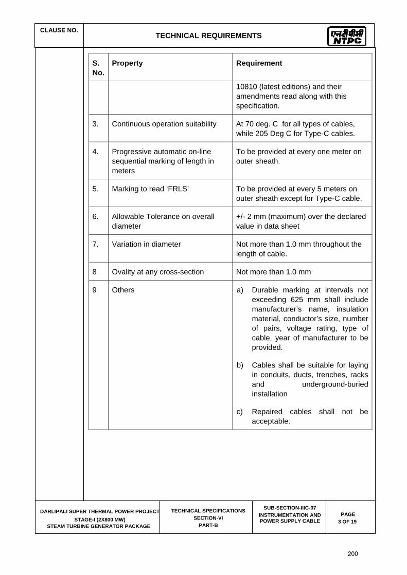
10810 (latest editions) and their amendments read along with this specification.
3. Continuous operation suitability At 70 deg. C for all types of cables, while 205 Deg C for Type-C cables.
4. Progressive automatic on-line sequential marking of length in meters
To be provided at every one meter on outer sheath.
5. Marking to read ‘FRLS’ To be provided at every 5 meters on outer sheath except for Type-C cable.
6. Allowable Tolerance on overall diameter
+/- 2 mm (maximum) over the declared value in data sheet
7. Variation in diameter Not more than 1.0 mm throughout the length of cable.
8 Ovality at any cross-section Not more than 1.0 mm
9 Others a) Durable marking at intervals not exceeding 625 mm shall include manufacturer’s name, insulation material, conductor’s size, number of pairs, voltage rating, type of cable, year of manufacturer to be provided.
b) Cables shall be suitable for laying in conduits, ducts, trenches, racks and underground-buried installation
c) Repaired cables shall not be acceptable.
200