specification sr- 142 - iec.co.il · pdf fileannexure “b” and summary of data...
TRANSCRIPT
JAN 2015
THE ISRAEL ELECTRIC CORPORATION LTD. PLANNING DEVELOPMENT AND TECHNOLOGY DIVISION
RELIABILITY AND H.V. EQUIPMENT DEPARTMENT
SR- 142 SR- 142
SPECIFICATION
SR- 142 AUTOMATIC RESONANCE
CONTROLLER FOR PETERSEN COILS
IN HV SUBSTATIONS

ANNEXURE “B” AND SUMMARY OF DATA SPECIFICATION SR-142
B-2
THE ISRAEL ELECTRIC CORPORATION LTD. PLANNING DEVELOPMENT AND TECHNOLOGY DIVISION
RELIABILITY AND H.V. EQUIPMENT DEPARTMENT
SPECIFICATION SR- 142
FOR
AUTOMATIC RESONANCE CONTROLLER FOR PETERSEN COILS IN HV SUBSTATIONS
VERSION A SIGNATURE VERSION B SIGNATURE
PREPARED M. BEN-YEHUDA 5.1.15
CHECKED DR. H. BEN HAIM
M. CHAUSHU
7.1.15
APPROVED D. AMDUR 8.1.15
ANNEXURE “B” AND SUMMARY OF DATA SPECIFICATION SR-142
B-3
TABLE OF CONTENTS
ANNEXURE “B” AND SUMMARY OF DATA
1. PURCHASER ......................................................................................................... 1
2. NAME OF PROJECT .............................................................................................. 1
3. SCOPE OF WORK ................................................................................................. 1
3.1. THE SCOPE OF SUPPLY SHALL INCLUDE: ......................................... 1
4. STANDARDS ......................................................................................................... 2
5. NETWORK and SECURITY SAFEGUARDS REQUIREMENTS ............................ 3
6. QUALITY management system and INTERCHANGEABILITY ............................ 3
7. SYSTEM DATA ...................................................................................................... 4
7.1. HV System type I: .................................................................................................. 4
7.2. HV System type II: ................................................................................................. 5
8. SPECIAL REQUIREMENTS FOR ENVIRONMENTAL PROTECTION ................... 5
9. Evaluation of Contractor’s Technical Proposal: ................................................. 6
10. MANUFACTURER / CONTRACTOR ...................................................................... 8
11. SERVICE CONDITIONS ......................................................................................... 9
11.1. CLIMATIC CONDITIONS ..................................................................... 9
11.2. ENVIRONMENTAL CONDITIONS ....................................................... 9
11.3. SEISMIC QUALIFICATION LEVEL .................................................... 10
11.4. ELECTROMAGNETIC COMPATIBILITY ........................................... 10
11.5. ACCELERATION DURING TRANSPORTATION .............................. 11
11.6. OTHER REQUIREMENTS ................................................................. 11
11.7. NAME PLATES .................................................................................. 11
12. TESTS ...................................................................................................................13
12.1. TESTS GENERAL .............................................................................. 13
12.2. TYPE TESTS FOR ARC/CIU ............................................................. 13
12.3. FACTORY ACCEPTANCE TESTS FOR ARC/CIU ............................ 15
13. Design and construction .....................................................................................16
13.1. GENERAL REQUIREMENTS............................................................. 16
13.2. METAL CUBICLE ............................................................................... 16
ANNEXURE “B” AND SUMMARY OF DATA SPECIFICATION SR-142
B-4
13.3. CONTROL METHOD ......................................................................... 19
13.4. HARDWARE REQUIREMENTS OF CONTROLLER ........................ 20
13.5. SOFTWARE REQUIREMENTS OF CONTROLLER .......................... 21
13.6. TUNING CONTROL ........................................................................... 23
13.7. I/O DATA OF CONTROLLER ............................................................. 24
13.8. COMMUNICATION OF CONTROLLER ............................................. 27
13.9. HUMAN MACHINE INTERFACE OF CONTROLLER ........................ 27
13.10. CURRENT INJECTION UNIT TECHNICAL DATA ............................ 28
13.11. I/O DATA OF CURRENT INJECTION UNIT ...................................... 29
13.12. MOUNTING REQUIREMENTS .......................................................... 31
14. DELIVERY, PACKING, SHIPMENT AND STORAGE ............................................32
15. commissioning .....................................................................................................34
16. QUALITY CONTROL, RMS, MAINTENANCE AND INSPECTION ....................37
16.1. QUALITY CONTROL .......................................................................... 37
16.2. RELIABILITY, MAINTAINABILITY AND SAFETY (RMS) ................ 38
16.3. MAINTENANCE AND INSPECTION .................................................. 38
17. technical documents to accompany the proposal .............................................39
18. technical documents after notification of award ...............................................42
19. COMMENTS BY MANUFACTURER ON ANNEXURE “B” AND SUMMARY OF DATA ..............................................................................................................................45
20. EXCEPTIONS FROM REQUIREMENTS ..............................................................46
21. CONFORMITY WITH PROPOSAL DOCUMENTS.................................................47
APPENDIXES:
No. 1: PROCEDURE FOR HANDLING OF NON-CONFORMANCES.
No. 2: RELIABILITY, MAINTAINABILITY AND SAFETY (RMS) REQUIREMENTS.
No. 3: QUALITY REQUIREMENTS Q-APP-02
No. 4: NETWORK & SECURITY SAFEGUARDS REQUIREMENTS FOR CONTROL PROTECTION AND DATA ACQUISITION SYSTEMS IN TRANSMISSION & SUBSTATION
No. 5: STANDARD EPD-3/1999- REVISION “F” - CONTROL CUBICLES WIRING - I.E.Co. STANDARD SPECIFICATION
No. 6: SPECIFICATION CL.172/00 FOR COATING THE ARC SUPPRESSION REACTORS
No. 7: SPECIFICATION FOR PAINTING ON GALVANIZED SURFACES BY WET or ELECTROSTATIC POWDER PAINTING CL-716

ANNEXURE “B” AND SUMMARY OF DATA SPECIFICATION SR-142
B - 1
SPECIFICATION
AUTOMATIC RESONANCE CONTROLLER
FOR PETERSEN COILS
1. PURCHASER
The Israel Electric Corporation Limited (I.E.Co.)
2. NAME OF PROJECT
AUTOMATIC RESONANCE CONTROLLER for PETERSEN COILS in two types, 24kV and 36kV, of HV network power subsystem.
3. SCOPE OF WORK
Design, develop, manufacture, test, preserve, pack, furnish for overseas shipping at port subject to co-ordination with Purchaser (for supply aboard), all in accordance with this Specification as detailed there under:
3.1. THE SCOPE OF SUPPLY SHALL INCLUDE:
ITEM 1 – Automatic Resonance Controller (ARC) for automatic tuning of the coil inductive current. The ARC shall be delivered loose.
ITEM 2 – Current Injection Unit (CIU) to assist tuning at very symmetrical networks. The CIU shall be delivered loose.
ITEM 3 - Spare parts and Renewal Materials:
Contractor is required to submit a detailed list of recommended Spare Parts and Renewal Materials including itemized prices and manufacturer catalog numbers.
ITEM 4 - Test Equipment and Maintenance Tools:
Contractor is required to submit a detailed list of recommended test equipment (including hardware and software for setting) and maintenance tools including itemized price and manufacturer catalog numbers.
ITEM 5 - Training Course
Training course which to be held in IECo facilities in order to attain satisfactorily IECo's staff proficiency at maintenance actions. The training course shall include schedule and issues.

ANNEXURE “B” AND SUMMARY OF DATA SPECIFICATION SR-142
B - 2
ITEM 6 - Erection and Commissioning Supervision – OPTIONAL
Erection and Commissioning Supervision to be held in IECo facilities. The duration of the Commissioning Program shall attain satisfactorily IECo staff proficiency at commissioning actions.
4. STANDARDS
All equipment shall be designed, constructed and tested in accordance with the requirements of the latest published Recommendations of the International Electrotechanical Commission (IEC) and their amendments.
In case the requirements in this Specification differ from those in IEC Publications in any aspect the Automatic Resonance Controllers shall conform to the requirements in this specification concerning that item.
All aspects, tests, etc., not covered by the IEC Recommendations, shall be executed according to the latest published issue of official, or otherwise approved standards of the Manufacturer's country. In such cases, the standards themselves shall be supplied.
In case of updating, amending, replacing or withdrawing any mention standard, after issuing this specification, the impact of these changing on the Specification will be subjected to agreements between the Contractor and the Purchaser. The following standards are applicable in the relevant parts to the individual components of the ARC/CIU:
IEC 60721-3-4(1996) Classification of groups of environmental parameters and their severities Section 4: Stationary use at non weather-protected locations
IEC 60255-26(2013) Measuring relays and protection equipment – Part 26: Electromagnetic compatibility requirements
IEC 60255-27(2013) Measuring relays and protection equipment – Part 27: Product safety requirements
IEC 60255-21-1(1988) Electrical relays Part 21: Vibration, shock, bump and seismic tests on measuring relays and protection equipment - Section 1: Vibration tests (sinusoidal
IEC 60255-21-2(1988) Electrical relays Part 21: Vibration, shock, bump and seismic tests on measuring relays and protection equipment - Section 2: Shock and bump tests
IEC 60255-21-3(1993) Electrical relays - Part 21: Vibration, shock, bump and seismic tests on measuring relays and protection equipment - Section 3: Seismic tests
IEC 60529(2013) Degrees of protection provided by enclosures (IP Code)
IEC 60068-2-30 (2005) Environmental testing – Part 2-30: Tests – Test Db: Damp heat, cyclic (12 + 12 h cycle)
ANNEXURE “B” AND SUMMARY OF DATA SPECIFICATION SR-142
B - 3
IEC 60068-2-78(2012) Environmental testing – Part 2-78: Tests – Test Cab: Damp heat, steady state
IEC 61000-4-2(2008) Electromagnetic compatibility (EMC) – Part 4-2: Testing and measurement techniques – Electrostatic discharge immunity test
IEC 61000-4-3(2010) Electromagnetic compatibility (EMC) – Part 4-3: Testing and measurement techniques – Radiated, radio- frequency, electromagnetic field immunity test
IEC 61000-4-4(2012) Electromagnetic compatibility (EMC) – Part 4-4: Testing and measurement techniques – Electrical fast transient/burst immunity test
IEC 61000-4-5(2005) Electromagnetic compatibility (EMC) – Part 4-5: Testing and measurement techniques – Surge immunity test
IEC 61000-4-6(2013) Electromagnetic compatibility (EMC) – Part 4-6: Testing and measurement techniques –Immunity to conducted disturbances, induced by radio-frequency fields
IEC 61000-4-8(2009) Electromagnetic compatibility (EMC) – Part 4-8: Testing and measurement techniques – Power frequency magnetic field immunity test
IEC 61000-4-11(2004) Electromagnetic compatibility (EMC) – Part 4-11: Testing and measurement techniques – Voltage dips, short interruptions and voltage variations immunity tests
IEC 61850 Communication networks and systems in substations
ISO 9001:2008 Quality management systems requirements
IEEE 695-2005 Recommended Practice for Seismic Design of Substations
5. NETWORK AND SECURITY SAFEGUARDS REQUIREMENTS
The proposed Automatic Resonance Controller (ARC) and Current Injection Unit (CIU) shall applied the data security requirements, measures and appropriate procedures security to prevent the exposure of the company's critical infrastructures, exposure to information security risks, as well as to prevent access by unauthorized parties requirements as required in APPENDIX No. 4
6. QUALITY MANAGEMENT SYSTEM AND INTERCHANGEABILITY
6.1. Quality Management System (QMS) – certification, documentation, implementation and other quality issues:

ANNEXURE “B” AND SUMMARY OF DATA SPECIFICATION SR-142
B - 4
6.1.1. The Contractor and its main subcontractors shell have a Quality Management System (QMS) certified at least to ISO 9001:2008 requirements.
6.1.2. A valid certification , demonstrating compliance with this requirement , granted by a Certification Body (CB) which is a part of or belong to an International Certification Network of CB's , should be submitted to Purchaser with the bid.
6.1.3. The CB should be accredited by an Accreditation Body which is a member of the International Accreditation Forum Multilateral Arrangement (IAF MLA).
6.1.4. The Certificate should bare the marks of the CB, the above indicated Certification Network of CB's and its Accreditation Body.
6.1.5. The scope of activities indicated in the certificate of the QMS, should specifically cover the scope of work required by the tender/spec. (i.e. design, testing and manufacturing).
6.1.6. Further to the Contractor's QMS certification by any certification body, the Purchaser shall have the right to audit and comment about its QMS.
6.1.7. It is the Contractor's responsibility to assure that its sub contractor's and supplier's QMS and scope of supply meet Purchaser's quality requirements as imposed by the Purchaser in the Specification.
6.1.8. The selection of Contractor's subcontractors (for the contract) shall be subjected to Purchaser's approval.
6.1.9. The Contractor and its main subcontractors shell have a Quality Management System (QMS) certified at least to ISO 9001:2008 requirements.
6.2. Quality Control: The quality control requirements should be according to Appendix No. 3.
6.3. Interchangeability:
All components of every ARC/CIU shall be identical to the same type component in every other ARC/CIU respectively. This will enable them to be interchangeable both electrically and mechanically. When so interchanged they shall perform their function equally well in every aspect.
7. SYSTEM DATA
The system has the following characteristics:
7.1. HV SYSTEM TYPE I:
7.1.1. Rated system voltage (line to line) (kV)…….……………… 22
7.1.2. Highest system voltage (line to line) (kV)…..……………… 24
ANNEXURE “B” AND SUMMARY OF DATA SPECIFICATION SR-142
B - 5
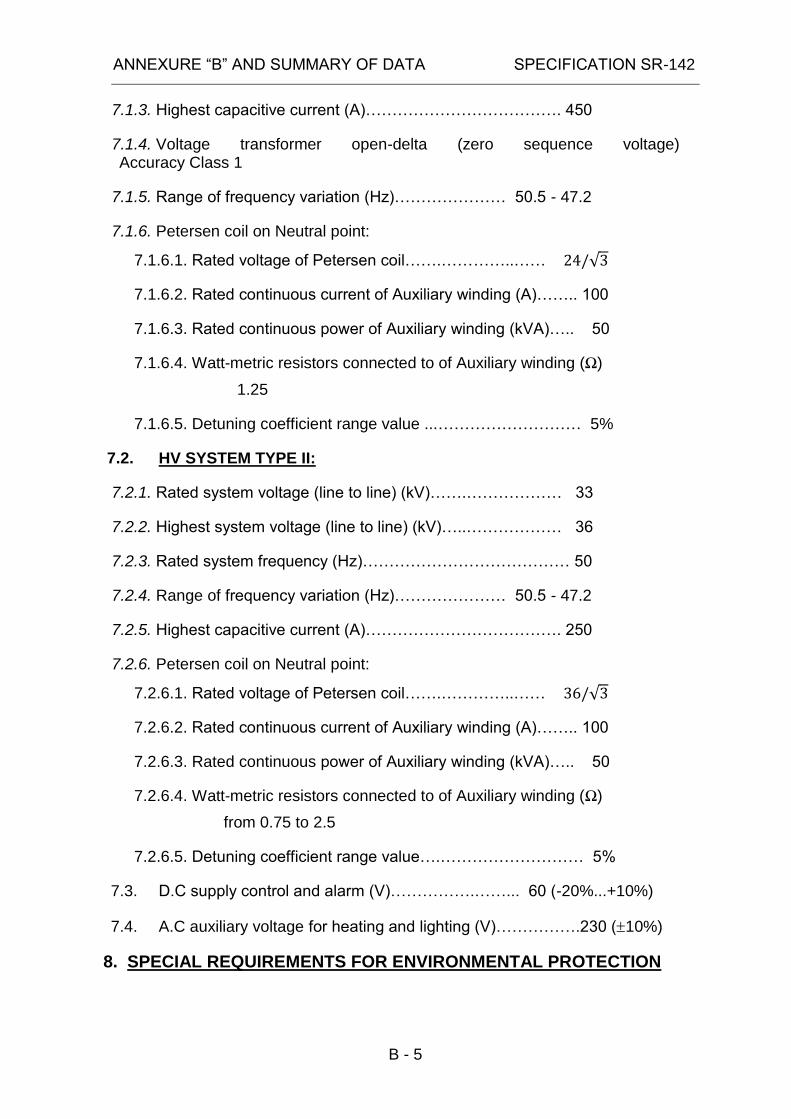
7.1.3. Highest capacitive current (A)………………………………. 450
7.1.4. Voltage transformer open-delta (zero sequence voltage) Accuracy Class 1
7.1.5. Range of frequency variation (Hz)………………… 50.5 - 47.2
7.1.6. Petersen coil on Neutral point:
7.1.6.1. Rated voltage of Petersen coil…….…………..…… √
7.1.6.2. Rated continuous current of Auxiliary winding (A)…….. 100
7.1.6.3. Rated continuous power of Auxiliary winding (kVA)….. 50
7.1.6.4. Watt-metric resistors connected to of Auxiliary winding (Ω)
1.25
7.1.6.5. Detuning coefficient range value ...……………………… 5%
7.2. HV SYSTEM TYPE II:
7.2.1. Rated system voltage (line to line) (kV)…….……………… 33
7.2.2. Highest system voltage (line to line) (kV)…..……………… 36
7.2.3. Rated system frequency (Hz)………………………………… 50
7.2.4. Range of frequency variation (Hz)………………… 50.5 - 47.2
7.2.5. Highest capacitive current (A)………………………………. 250
7.2.6. Petersen coil on Neutral point:
7.2.6.1. Rated voltage of Petersen coil…….…………..…… √
7.2.6.2. Rated continuous current of Auxiliary winding (A)…….. 100
7.2.6.3. Rated continuous power of Auxiliary winding (kVA)….. 50
7.2.6.4. Watt-metric resistors connected to of Auxiliary winding (Ω)
from 0.75 to 2.5
7.2.6.5. Detuning coefficient range value….……………………… 5%
7.3. D.C supply control and alarm (V)…………….……... 60 (-20%...+10%)
7.4. A.C auxiliary voltage for heating and lighting (V)…………….230 (10%)
8. SPECIAL REQUIREMENTS FOR ENVIRONMENTAL PROTECTION
ANNEXURE “B” AND SUMMARY OF DATA SPECIFICATION SR-142
B - 6
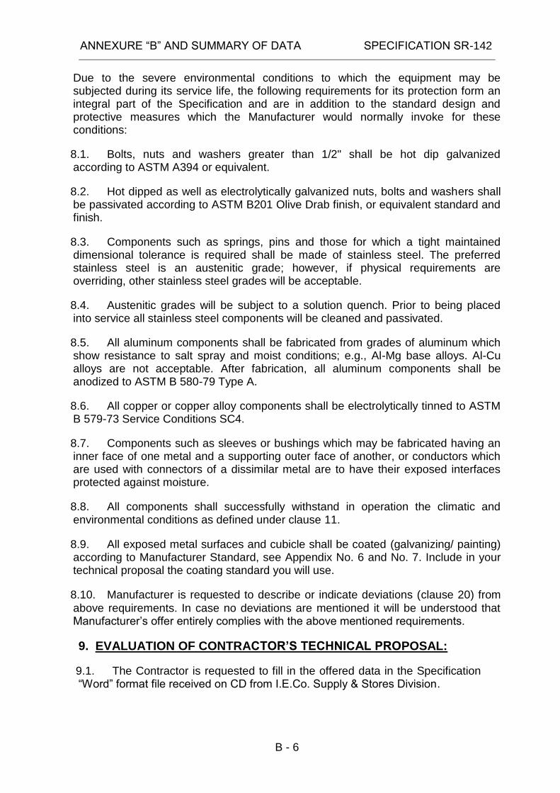
Due to the severe environmental conditions to which the equipment may be subjected during its service life, the following requirements for its protection form an integral part of the Specification and are in addition to the standard design and protective measures which the Manufacturer would normally invoke for these conditions:
8.1. Bolts, nuts and washers greater than 1/2" shall be hot dip galvanized according to ASTM A394 or equivalent.
8.2. Hot dipped as well as electrolytically galvanized nuts, bolts and washers shall be passivated according to ASTM B201 Olive Drab finish, or equivalent standard and finish.
8.3. Components such as springs, pins and those for which a tight maintained dimensional tolerance is required shall be made of stainless steel. The preferred stainless steel is an austenitic grade; however, if physical requirements are overriding, other stainless steel grades will be acceptable.
8.4. Austenitic grades will be subject to a solution quench. Prior to being placed into service all stainless steel components will be cleaned and passivated.
8.5. All aluminum components shall be fabricated from grades of aluminum which show resistance to salt spray and moist conditions; e.g., Al-Mg base alloys. Al-Cu alloys are not acceptable. After fabrication, all aluminum components shall be anodized to ASTM B 580-79 Type A.
8.6. All copper or copper alloy components shall be electrolytically tinned to ASTM B 579-73 Service Conditions SC4.
8.7. Components such as sleeves or bushings which may be fabricated having an inner face of one metal and a supporting outer face of another, or conductors which are used with connectors of a dissimilar metal are to have their exposed interfaces protected against moisture.
8.8. All components shall successfully withstand in operation the climatic and environmental conditions as defined under clause 11.
8.9. All exposed metal surfaces and cubicle shall be coated (galvanizing/ painting) according to Manufacturer Standard, see Appendix No. 6 and No. 7. Include in your technical proposal the coating standard you will use.
8.10. Manufacturer is requested to describe or indicate deviations (clause 20) from
above requirements. In case no deviations are mentioned it will be understood that Manufacturer’s offer entirely complies with the above mentioned requirements.
9. EVALUATION OF CONTRACTOR’S TECHNICAL PROPOSAL:
9.1. The Contractor is requested to fill in the offered data in the Specification “Word” format file received on CD from I.E.Co. Supply & Stores Division.
ANNEXURE “B” AND SUMMARY OF DATA SPECIFICATION SR-142
B - 7
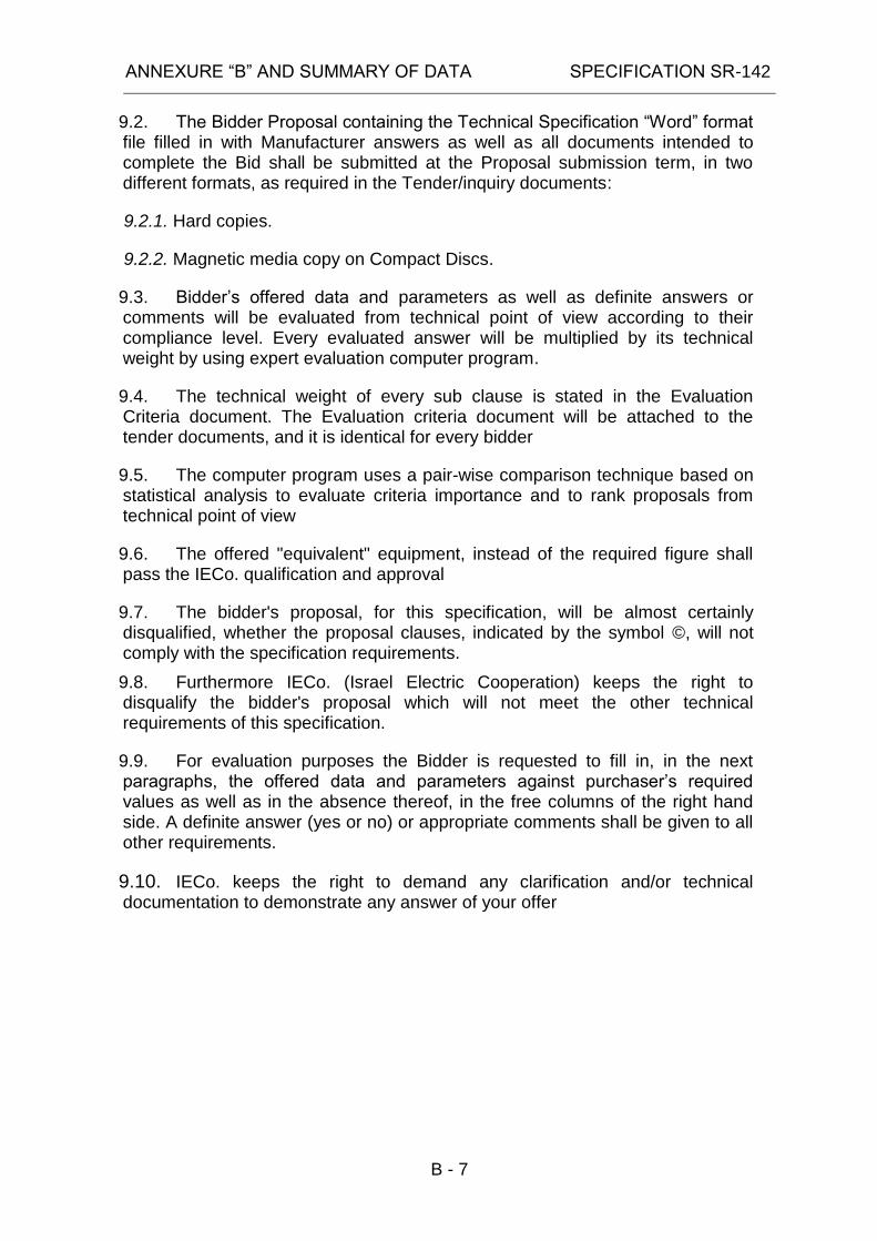
9.2. The Bidder Proposal containing the Technical Specification “Word” format file filled in with Manufacturer answers as well as all documents intended to complete the Bid shall be submitted at the Proposal submission term, in two different formats, as required in the Tender/inquiry documents:
9.2.1. Hard copies.
9.2.2. Magnetic media copy on Compact Discs.
9.3. Bidder’s offered data and parameters as well as definite answers or comments will be evaluated from technical point of view according to their compliance level. Every evaluated answer will be multiplied by its technical weight by using expert evaluation computer program.
9.4. The technical weight of every sub clause is stated in the Evaluation Criteria document. The Evaluation criteria document will be attached to the tender documents, and it is identical for every bidder
9.5. The computer program uses a pair-wise comparison technique based on statistical analysis to evaluate criteria importance and to rank proposals from technical point of view
9.6. The offered "equivalent" equipment, instead of the required figure shall pass the IECo. qualification and approval
9.7. The bidder's proposal, for this specification, will be almost certainly disqualified, whether the proposal clauses, indicated by the symbol ©, will not comply with the specification requirements.
9.8. Furthermore IECo. (Israel Electric Cooperation) keeps the right to disqualify the bidder's proposal which will not meet the other technical requirements of this specification.
9.9. For evaluation purposes the Bidder is requested to fill in, in the next paragraphs, the offered data and parameters against purchaser’s required values as well as in the absence thereof, in the free columns of the right hand side. A definite answer (yes or no) or appropriate comments shall be given to all other requirements.
9.10. IECo. keeps the right to demand any clarification and/or technical documentation to demonstrate any answer of your offer

ANNEXURE “B” AND SUMMARY OF DATA SPECIFICATION SR-142
B - 8
10. MANUFACTURER / CONTRACTOR
Name of Contractor
REQUIRED OFFERED
10.1. Contractor's name and address
10.2. Manufacturer's name and address (if different from Contractor)
10.3. Manufacturer's name and address of all subcontractors or sub suppliers. (Please insert list, name, address and status of Quality Management System, as ISO 9001:2008
10.4. Automatic Resonance Controller and Current Injection Unit type/model name (denomination)
Indicate also part number of manufacturer's products
10.5. Contractor's offer number
10.6. The offered type of Automatic Resonance Controller and Current Injection Unit shall be a proven design (not a prototype) with high experience in work (Manufacturer's declaration). Offerers shall provide with a reference list of controllers sold, specifying the company to which it was sold.
10.7. Period time of supplying which begins on order receiving time and ends on products delivery time

ANNEXURE “B” AND SUMMARY OF DATA SPECIFICATION SR-142
B - 9
11. SERVICE CONDITIONS
Name of Contractor
REQUIRED OFFERED
11.1. CLIMATIC CONDITIONS
11.1.1. Environmental parameters according to IEC 60721-3-4
11.1.2. Permissible ambient air temperature :
11.1.2.1. Maximum (C) + 50
11.1.2.2. Minimum (C) - 5
11.1.2.3. Yearly average(C) + 22
11.1.3. Permissible humidity :
11.1.3.1. Low relative/absolute humidity (%//g/m3)
4/0.003
11.1.3.2. High relative/absolute humidity (%//g/m3)
100/36
11.1.4. Air pressure:
11.1.4.1. Low air pressure (KPa) 70
11.1.4.2. High air pressure (KPa) 106
11.1.5. Rain intensity [mm/min] 15
11.1.6. Solar radiation: heating effect of solar radiation [W/m2]
1120
11.1.7. Maximum wind velocity measured at 10m above grade bare area at 3 sec duration.[m/sec] 1
44
11.2. ENVIRONMENTAL CONDITIONS
11.2.1. Environmental parameters according to ...... IEC 60721-3-4
1 Considering a 50 year mean return period

ANNEXURE “B” AND SUMMARY OF DATA SPECIFICATION SR-142
B - 10
11. SERVICE CONDITIONS
Name of Contractor
REQUIRED OFFERED
11.2.2. Severe atmospheric and industrial air pollution, dust, salt spray and sandstorms .............
11.2.3. Permissible altitude over the sea level [m] .......................................................................... .
1000
11.2.4. Water from sources other than rain: Spraying water and water jets with water velocity (m/sec) ......................................................
15
11.2.5. Chemically active substances according to ............................................................
Table IV 4C3
11.2.6. Mechanically active substances according to ............................................................
Table V 4S3
11.2.7. Sand [mg/m3] ............................................... 1000
11.2.8. Dust suspension [mg/m3] ............................. 15
11.2.9. Dust sedimentation (mg/m3.h] ...................... 40
11.3. SEISMIC QUALIFICATION LEVEL
11.3.1. The seismic design of the equipment and their supports shall be based on the seismic qualification requirements stated in standard .................................................................
IEEE 693-2005
11.3.2. The required seismic qualification level for equipment qualification shall be ........................
Moderate level
11.4. ELECTROMAGNETIC COMPATIBILITY ©
The equipment may be installed in an environment having the following maximum severity levels for disturbances according to ......................................
Indicate if it is complied with other standard
IEC 60255-26
11.4.1. Severity level for radiated radio frequency electromagnetic field (V/m) ....................
10
11.4.2. Severity level for electrostatic discharge (kV) .........................................................................
4

ANNEXURE “B” AND SUMMARY OF DATA SPECIFICATION SR-142
B - 11
11. SERVICE CONDITIONS
Name of Contractor
REQUIRED OFFERED
11.4.3. Severity level for power frequency magnetic field (V/m) ................................................
30
11.4.4. Severity level for fast transients (kV) 2
11.4.5. Severity level for slow damped oscillatory wave (kV) ...............................................
2.5
11.5. ACCELERATION DURING TRANSPORTATION
11.5.1. Vibration and shocks (non-stationary vibrations including shocks). The expected accelerations on the ARC/CIU transported on road may be :
11.5.1.1. Longitudinal acceleration ....................... 2.0g
11.5.1.2. Transversal acceleration ....................... 1.2g
11.5.1.3. Vertical acceleration .............................. 1.2g
11.6. OTHER REQUIREMENTS
11.6.1. Storage temperature limits :
11.6.1.1. Maximum (ºC) +50
11.6.1.2. Minimum (ºC) -5
11.6.2. Specify if special measures (air condition) should be taken for indoor mounting
11.6.3. The Automatic Resonance Controller and Current Injection Unit Shall be vermin proof
11.7. NAME PLATES
11.7.1. Each cubicle or panel shall be provided with Name Plates made of waterproof material, fitted in a visible position, including the following data:

ANNEXURE “B” AND SUMMARY OF DATA SPECIFICATION SR-142
B - 12
11. SERVICE CONDITIONS
Name of Contractor
REQUIRED OFFERED
11.7.2. Electrical scheme with denomination of each components, on inner side of the door ..........
11.7.3. Label (60x150mm), on outer side of the door, including: Manufacturer’s data, Cubicle/Panel name and type, I.E.Co. Order number, Technical Specification number and year of manufacture

ANNEXURE “B” AND SUMMARY OF DATA SPECIFICATION SR-142
B - 13
12. TESTS
Name of Contractor
REQUIRED OFFERED
12.1. TESTS GENERAL
12.1.1. Test reports of the proposed type equipment or similar equipment shall be submitted to prove that the design has the capability to meet all the ratings as specified in ANNEXURE "B" ......................................................
12.1.2. Type Test on the offered equipment shall be carried out as specified at a neutral Laboratory (e.g. KEMA) and shall be submitted to Purchaser with the tender .......................................
12.1.3. Production (Factory Acceptance) Tests shall be performed to check the quality and uniformity of the workmanship and materials used in the manufacture of all items in the Scope of Supply ................................................................
12.1.4. Each test value/result shall be indicated with permissible tolerance for .................................
12.1.5. Contractor shall notify the Purchaser eight (8) weeks before the date of execution the Factory Acceptance Tests ......................................
12.1.6. Contractor shall submit a list of all tests to be performed on site, after mounting of the offered equipment and during operation .................
12.2. TYPE TESTS FOR ARC/CIU ©
Type tests shall include the following tests:
12.2.1. Test of degree of protection test according to ............................................................................
IEC 60529
12.2.2. Impulse voltage test with 2.5kV impulses
waveform 1.2/50 s on all inputs and outputs circuits according to ................................................
IEC 60255-27
12.2.3. Dielectric test with 2.5kV-50Hz, 1min. of all inputs and outputs circuits according to ..................
IEC 60255-27

ANNEXURE “B” AND SUMMARY OF DATA SPECIFICATION SR-142
B - 14
12. TESTS
Name of Contractor
REQUIRED OFFERED
12.2.4. Radiated radio frequency electromagnetic field test of enclosure port according to ..................
IEC 61000-4-3
12.2.5. Electrostatic discharge test of enclosure port according to .....................................................
IEC 61000-4-2
12.2.6. Power frequency magnetic field test of enclosure port according to ....................................
IEC 61000-4-8
12.2.7. Conducted disturbance induced by radio-frequency fields test of power supply, input/output and communication ports and functional earth according to ............................................................
IEC 61000-4-6
12.2.8. Fast transient test of power supply, input/output, communication ports and functional earth according to ...................................................
IEC 61000-4-4
12.2.9. Surge test of power supply, input/output and communication ports according to ...................
IEC 61000-4-5
12.2.10. AC and DC voltage dips and interruption tests of power supply ports according to ................
IEC 61000-4-11
12.2.11. DC voltage gradual shutdown/start-up of power supply ports according to .............................
IEC 60255-26
12.2.12. Damp heat steady state test, according to . IEC 60068-2-78
12.2.13. Cyclic Temperature with humidity test, according to ............................................................
IEC 60068-2-30
12.2.14. Vibration test class 1, according to ............. IEC 60255 PT21-1
12.2.15. Shock and Bump test class 1, according to ............................................................................
IEC 60255 PT21-2
12.2.16. Seismic test class 2, according to .............. IEC 60255 PT21-3
12.2.17. Power consumption and overload test .......

ANNEXURE “B” AND SUMMARY OF DATA SPECIFICATION SR-142
B - 15
12. TESTS
Name of Contractor
REQUIRED OFFERED
12.2.18. Accuracy test for measuring elements and timers depending on frequency and amplitude of power supply and ambient temperature ............................................................
12.2.19. Operating and resetting time test ..............
12.2.20. Tests to prove all basic and additional functions of the required equipment
12.3. FACTORY ACCEPTANCE TESTS FOR ARC/CIU
The factory acceptance test shall be performed on each manufactured item and shall include the followings tests:
12.3.1. Dielectric test with 2.5kV-50Hz, 1min. of all inputs and outputs circuits according to ..................
IEC 60255-27
©
12.3.2. Checking of all hardware and software functions .................................................................
12.3.3. Measurement of pick-up values ...................
12.3.4. Measurement of tolerances and errors for pick-up values and timers .......................................
12.3.5. Functional tests including test of input and output circuits .........................................................
12.3.6. The factory acceptance test shall be carried out in the presence of Purchaser representatives .......................................................

ANNEXURE “B” AND SUMMARY OF DATA SPECIFICATION SR-142
B - 16
13. DESIGN AND CONSTRUCTION
Name of Contractor
REQUIRED OFFERED
13.1. GENERAL REQUIREMENTS
13.1.1. The Automatic Resonance Controller and Current Injection is intended to operate with Petersen Coil in 24kV and 36kV network
13.1.2. Type of the Current Injection for indoor version (denomination and manufacturer name)
13.1.3. Type of the Resonance Controller for rack 19" version (denomination and manufacturer name)
13.2. METAL CUBICLE
13.2.1. All necessary automatic control, protective relays, contactors etc., shall be provided by Contractor and assembled in a dust proof and weatherproof hot dip galvanized METAL CUBICLE, factory wired and tested
13.2.2. The Metal Cubicle shall be installed at indoor
13.2.3. Cubicle Design :
13.2.4. Access to the internal equipment of the cubicle shall be from the front only
13.2.5. Any manually controlled equipment shall not be mounted higher than 180 cm or lower than 60 cm.
13.2.6. The top part of the cubicle shall be provided with natural air ventilation to permit heat dissipation, having a degree of protection of
IP 51
13.2.7. Filters shall be provided behind the ventilation apertures.
13.2.8. The bottom part of the cubicle shall be of tropical design having a degree of protection of
IP 54
13.2.9. Two (2) lifting eyes at least shall be provided for lifting completely cubicle
ANNEXURE “B” AND SUMMARY OF DATA SPECIFICATION SR-142
B - 17
13. DESIGN AND CONSTRUCTION
Name of Contractor
REQUIRED OFFERED
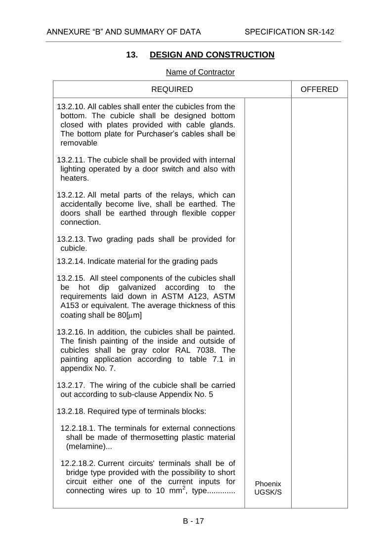
13.2.10. All cables shall enter the cubicles from the bottom. The cubicle shall be designed bottom closed with plates provided with cable glands. The bottom plate for Purchaser’s cables shall be removable
13.2.11. The cubicle shall be provided with internal lighting operated by a door switch and also with heaters.
13.2.12. All metal parts of the relays, which can accidentally become live, shall be earthed. The doors shall be earthed through flexible copper connection.
13.2.13. Two grading pads shall be provided for cubicle.
13.2.14. Indicate material for the grading pads
13.2.15. All steel components of the cubicles shall be hot dip galvanized according to the requirements laid down in ASTM A123, ASTM A153 or equivalent. The average thickness of this
coating shall be 80[m]
13.2.16. In addition, the cubicles shall be painted. The finish painting of the inside and outside of cubicles shall be gray color RAL 7038. The painting application according to table 7.1 in appendix No. 7.
13.2.17. The wiring of the cubicle shall be carried out according to sub-clause Appendix No. 5
13.2.18. Required type of terminals blocks:
12.2.18.1. The terminals for external connections shall be made of thermosetting plastic material (melamine)...
12.2.18.2. Current circuits' terminals shall be of bridge type provided with the possibility to short circuit either one of the current inputs for connecting wires up to 10 mm2, type.............
Phoenix UGSK/S

ANNEXURE “B” AND SUMMARY OF DATA SPECIFICATION SR-142
B - 18
13. DESIGN AND CONSTRUCTION
Name of Contractor
REQUIRED OFFERED
12.2.18.3. Control circuits, alarm circuits and voltage circuits for connecting wires up to 4 mm2, type.
Phoenix SSK UK6N
13.2.19. Equivalent terminals may be used, subjected of Purchaser approval.....................
13.2.20. Compression type (solder-less) lugs or ferrules shall be applied on the ends of all stranded wired for connection to terminal block or to relays.
For connection to screw type terminals, ring tongue tin plated lugs shall be used...............
13.2.21. Each terminal block shall be provided with not less than 10% spare terminals..............
13.2.22. The blocks shall be spaced to allow ample clearance on all sides. Cable supports shall be provided for Purchaser’s wiring.............
13.2.23. The terminal blocks shall not be mounted lower than 30cm from the bottom glands plate.
13.2.24. Terminals associated with individual items of equipment shall be grouped for convenient cable connection
13.2.25. Any non-metallic components such as terminal blocks, wired ducts, wired troughs, wired cleats, cable ties, etc. shall be manufactured from non-burning materials as defined by ASTM D635
13.2.26. Identification labels for wiring indicating destination, address (at both ends) shall be provided.
13.2.27. Wired and wired groups shall be installed in plastic wire ducts or packed in neatly formed bundles securely clamped or tired together and supported form the cubicle framework. Not more than 30 wires shall be bundled together in wire hinge loops

ANNEXURE “B” AND SUMMARY OF DATA SPECIFICATION SR-142
B - 19
13. DESIGN AND CONSTRUCTION
Name of Contractor
REQUIRED OFFERED
13.2.28. No more than one conductor shall be connected to any one terminal point of a terminal block
13.2.29. All spare contacts from the auxiliary relays and control switches shall be wired to the terminal blocks
13.2.30. Additional details of the circuits in the cubicles as well as design details will be settled between Contractor and Purchaser later
13.3. CONTROL METHOD
13.3.1. The coil current shall be adjustable continuously in range of rated current with step less adjustable plunger core coil .................
13.3.2. The Controller shall be able to find the correct tuning position of the coil even in very symmetrical networks with non-negligible disturbances, by current injection into auxiliary winding of Petersen coil
©
13.3.3. The Controller shall also operate normally if a fixed (non-adjustable) Petersen Coil is connected in parallel with the adjustable one. In this case, the fixed coil parameters are set into the Controller.
13.3.4. The Petersen Coil tuning in normal operation regimes while zero sequence voltage Uo applied to the Petersen Coil is, as a rule, less than 5% of its maximum value.
13.3.5. In additional to the automatic mode, a manual Petersen Coil tuning mode shall be provided. Change-over of these modes shall be performed with the aid of the Controller’s keyboard and through a binary input for remote change-over.
13.3.6. Current Injection can be switched on continuously or intermittently
ANNEXURE “B” AND SUMMARY OF DATA SPECIFICATION SR-142
B - 20
13. DESIGN AND CONSTRUCTION
Name of Contractor
REQUIRED OFFERED
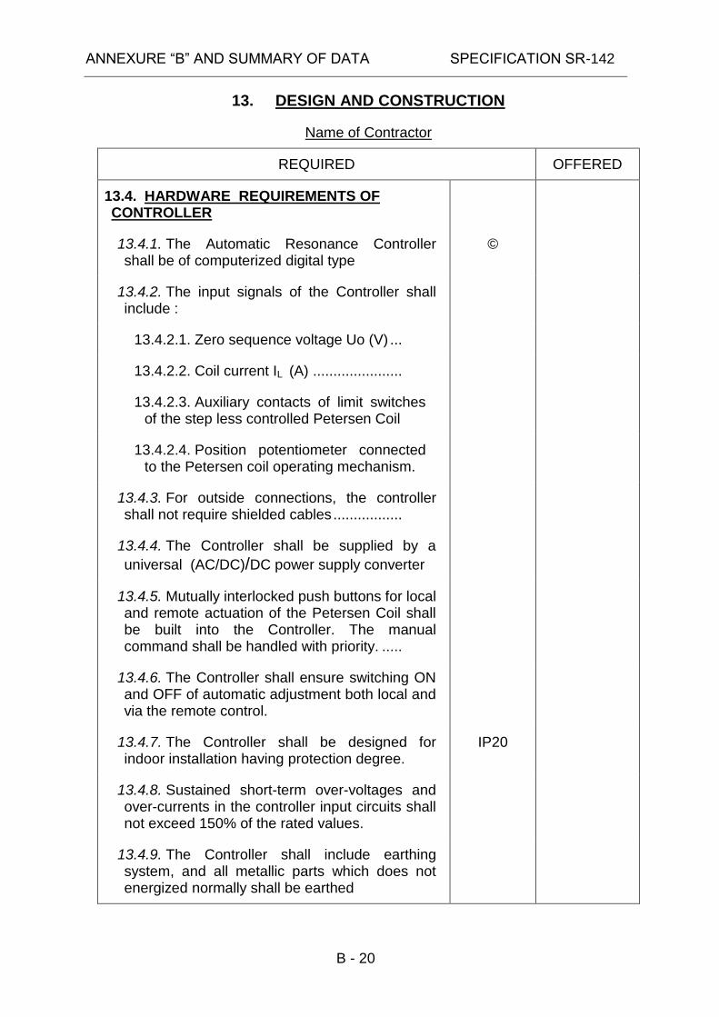
13.4. HARDWARE REQUIREMENTS OF CONTROLLER
13.4.1. The Automatic Resonance Controller shall be of computerized digital type
©
13.4.2. The input signals of the Controller shall include :
13.4.2.1. Zero sequence voltage Uo (V) ...
13.4.2.2. Coil current IL (A) ......................
13.4.2.3. Auxiliary contacts of limit switches of the step less controlled Petersen Coil
13.4.2.4. Position potentiometer connected to the Petersen coil operating mechanism.
13.4.3. For outside connections, the controller shall not require shielded cables .................
13.4.4. The Controller shall be supplied by a
universal (AC/DC)/DC power supply converter
13.4.5. Mutually interlocked push buttons for local and remote actuation of the Petersen Coil shall be built into the Controller. The manual command shall be handled with priority. .....
13.4.6. The Controller shall ensure switching ON and OFF of automatic adjustment both local and via the remote control.
13.4.7. The Controller shall be designed for indoor installation having protection degree.
IP20
13.4.8. Sustained short-term over-voltages and over-currents in the controller input circuits shall not exceed 150% of the rated values.
13.4.9. The Controller shall include earthing system, and all metallic parts which does not energized normally shall be earthed

ANNEXURE “B” AND SUMMARY OF DATA SPECIFICATION SR-142
B - 21
13. DESIGN AND CONSTRUCTION
Name of Contractor
REQUIRED OFFERED
13.5. SOFTWARE REQUIREMENTS OF CONTROLLER
13.5.1. The Controller shall have a built in automatically operated test for alerting in case of internal failure.
13.5.2. The Controller shall provide relevant signals in case of faults in its external circuits like, power supply interruptions, open or short-circuits in coil control units ..........................
13.5.3. All settings (or most of them) shall be done by software
13.5.4. The Controller shall memorize every retuning event and pertaining information, including:
13.5.4.1. Retuning date and time ..............
13.5.4.2. Petersen Coil current in the exact tuning position ........................................
13.5.4.3. Uo value on the retuning completion
13.5.4.4. Detuning (v) and damping (d) value
13.5.5. The Controller shall be provided with a setting of the type of compensation over or under, in the range of up to 20% .................
13.5.6. The Controller has to compute a correction to Petersen Coil position, taking into account the Petersen Coil non-linearity in order to provide experimental “impedance-voltage” curves depending on the actual Petersen Coil.
13.5.7. The full range adjustment time of operating mechanism (moving time from one end coil position to the other end) and the Controller delay time must be mutually coordinated .................................................

ANNEXURE “B” AND SUMMARY OF DATA SPECIFICATION SR-142
B - 22
13. DESIGN AND CONSTRUCTION
Name of Contractor
REQUIRED OFFERED
13.5.8. The Coil position shall be indicated by a potentiometer in the operating mechanism and can also be obtained by computation the ratio Uo/Io.
13.5.9. The Controller shall be provided with a counter to accumulate the number of automatic adjustments .................................................
13.5.10. The Controller shall ensure setting of the maximum adjustable current of the Petersen Coil
13.5.11. At each retuning the Controller shall compute and display the state parameters of the compensated network:
©
13.5.11.1. Detuning v................................
13.5.11.2. Damping d ...............................
13.5.11.3. Asymmetry k ...........................
13.5.12. The following signals shall be provided by the Controller:
13.5.12.1. Insufficient input voltage ..........
13.5.12.2. Too high asymmetry ................
13.5.12.3. Earth fault ................................
13.5.12.4. Insufficient Petersen Coil capacity...
13.5.12.5. Excessive insulation leakage ...
ANNEXURE “B” AND SUMMARY OF DATA SPECIFICATION SR-142
B - 23
13. DESIGN AND CONSTRUCTION
Name of Contractor
REQUIRED OFFERED
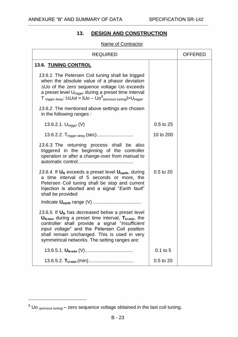
13.6. TUNING CONTROL
13.6.1. The Petersen Coil tuning shall be trigged when the absolute value of a phasor deviation
Uo of the zero sequence voltage Uo exceeds a preset level Utrigger during a preset time interval
T trigger delay: lUol = lUo – Uo8(previous tuning)l>Utrigger
13.6.2. The mentioned above settings are chosen in the following ranges :
13.6.2.1. Utrigger (V) 0.5 to 25
13.6.2.2. Ttrigger delay (sec) ........................... 10 to 200
13.6.3. The returning process shall be also triggered in the beginning of the controller operation or after a change-over from manual to automatic control .........................................
13.6.4. If UN exceeds a preset level Uearth, during a time interval of 5 seconds or more, the Petersen Coil tuning shall be stop and current Injection is aborted and a signal “Earth fault” shall be provided
Indicate Uearth range (V) ....................................
0.5 to 20
13.6.5. If UN has decreased below a preset level UN-min during a preset time interval, TU-min, the controller shall provide a signal “Insufficient input voltage” and the Petersen Coil position shall remain unchanged. This is used in very symmetrical networks. The setting ranges are:
13.6.5.1. UN-min (V).................................... 0.1 to 5
13.6.5.2. TU-min (min) ................................. 0.5 to 20
8 Uo (previous tuning) – zero sequence voltage obtained in the last coil tuning.

ANNEXURE “B” AND SUMMARY OF DATA SPECIFICATION SR-142
B - 24
13. DESIGN AND CONSTRUCTION
Name of Contractor
REQUIRED OFFERED
13.6.6. If UN exceeds a preset level UN-max, the Petersen Coil tuning shall be terminated and a signal “Too high asymmetry” shall be provided ....................................................................
Indicate UN-max range (V) ...................................
2 to 25
13.6.7. If the coil position changes in the process of tuning and the condition for generation of the signal “Insufficient input voltage” is not fulfilled but to reach the preset deviation value is impossible, then a signal “Insufficient Petersen Coil capacity” shall be provided and the coil shall be set in its maximum current position.
13.6.8. If damping exceeds a preset value (which can be set in a range of 0.03-0.40) a signal “Excessive insulation leakage” shall be provided ....................................................................
13.6.9. Tuning with Current Injection shall be calculate cyclic by using UOPEN-DELTA ICURRENT-
INJECTION and after changing control form manual to remote control
13.6.10. The Petersen Coil tuning accuracy under earth-fault conditions shall be not less than (%) ......................................................
With possibility of its detuning to a preset deviation value in the range of (%) ............................
The deviation value shall be displayed
± 0.1
± 20
13.6.11. The mentioned accuracy shall be kept under fluctuations of Uo voltage when its amplitude fluctuates in the limits of ±15%, with a frequency in the range of (Hz) .....................
0.1 to 2.0
13.6.12. The Controller shall be non-sensitive to power network load changes by using Current Injection unit.
13.7. I/O DATA OF CONTROLLER
13.7.1. The auxiliary DC power supply shall be provided through DC/DC converter.

ANNEXURE “B” AND SUMMARY OF DATA SPECIFICATION SR-142
B - 25
13. DESIGN AND CONSTRUCTION
Name of Contractor
REQUIRED OFFERED
13.7.1.1. Rated DC supply voltage (V) ..... 220
©
13.7.1.2. Voltage operating range (%) ...... +10 to –20
©
13.7.1.3. Power consumption quiescent (W) ...............................................................
13.7.1.4. Power consumption pick-up (W)
13.7.1.5. Bridging time during failure or short-circuit of DC supply voltage (ms) ............
50
13.7.2. Input quantities :
13.7.2.1. Rated current of CT's (A) ........... 5
©
13.7.2.2. Rated frequency (Hz) ................. 50
13.7.2.3. Load carrying capacity of current input continuous (A) ...............................
2xIn
13.7.2.4. Load carrying capacity of current input for 1 sec. (A)……….. .....................
13.7.2.5. Rated zero sequence voltage Un (V) ..........................................................
110
©
13.7.2.6. Continuous over voltage in voltage circuit (V) ................................................
1.2xUn
13.7.2.7. Rated burden for voltage circuit (VA) ........................................................
13.7.2.8. Rated burden for current circuit not more than (VA/phase) ............................
0.5
13.7.3. Signaling outputs :
13.7.3.1. Type of signaling output, static or electromechanical ..................................

ANNEXURE “B” AND SUMMARY OF DATA SPECIFICATION SR-142
B - 26
13. DESIGN AND CONSTRUCTION
Name of Contractor
REQUIRED OFFERED
13.7.3.2. Number of optical signal annunciation (LED) ................................
13.7.3.3. Number of signaling relays ........
13.7.3.4. NO contacts per relay ................
13.7.3.5. Maximum operating time of signaling relay (ms) ................................
13.7.3.6. Thermal ratings of contacts carry for 0.5 sec ..............................................
13.7.3.7. Make power at 220VDC (W) ...... 300
13.7.3.8. Breaking current for electromechanical signaling output at 220VDC and L/R less than 40 msec (A)
0.1
13.7.4. Optocoupler inputs :
13.7.4.1. Number of optocoupler inputs ....
13.7.4.2. Operating time (ms) ...................
13.7.4.3. Rated voltage for optocoupler (VDC) .....................................................
220
©
13.7.4.4. Input signal voltage low/high (V/V) ...............................................................
13.7.4.5. Maximum signal current (mA) ....
13.7.5. Analog output
13.7.5.1. Number of Analog channels ......
13.7.5.2. Signal current range (mA) .........
13.7.6. The internal real-time clock of the unit shall be synchronized via an input by an external synchronizing system.
IRIG B input
13.7.7. The accuracy of time synchronizing shall be of 1msec. ...............................................

ANNEXURE “B” AND SUMMARY OF DATA SPECIFICATION SR-142
B - 27
13. DESIGN AND CONSTRUCTION
Name of Contractor
REQUIRED OFFERED
13.8. COMMUNICATION OF CONTROLLER
13.8.1. Operator terminal interface by using serial interface for communication with a PC terminal (type) ...........................................................
©
USB/RJ45
13.8.2. Serial interface for communication with a Substation Control System or for communication over telephone networks using a modem. The transmission protocol for communication with the substation control system shall comply with the requirement of IEC 61850 standard.
©
13.8.2.1. Data transfer interface connection type ........................................................
RJ45/
RS485
13.8.2.2. Data transfer interface connection transmission speed (baud) .....................
13.8.2.3. Data transfer interface connection transmission distance (m) ......................
13.9. HUMAN MACHINE INTERFACE OF CONTROLLER
The Controller unit shall be provided with the following Human Machine Interface (HMI) facilities :
13.9.1. The HMI operating language shall be English.
©
13.9.2. The HMI facilities shall be used for Controller setting, for data exchange with a switching station control, for reading of events, for reading of primary system data (voltages, currents, etc.) and for diagnostic purposes.
13.9.3. The Controller shall be provided with a LCD screen for displaying setting, data exchange, events reading and diagnostic data. ....................................................................
13.9.3.1. Indicate screen size [mm]
13.9.3.2. Indicate screen resolution [pixels]
ANNEXURE “B” AND SUMMARY OF DATA SPECIFICATION SR-142
B - 28
13. DESIGN AND CONSTRUCTION
Name of Contractor
REQUIRED OFFERED
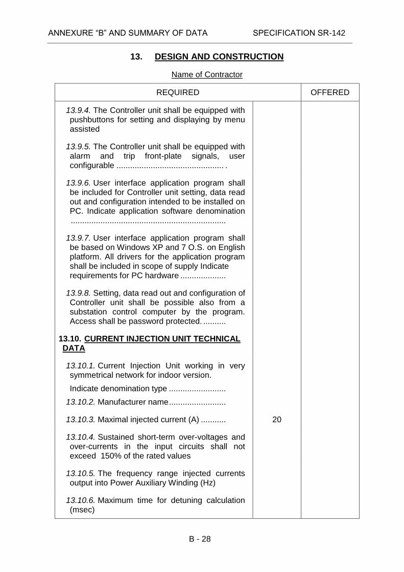
13.9.4. The Controller unit shall be equipped with pushbuttons for setting and displaying by menu assisted
13.9.5. The Controller unit shall be equipped with alarm and trip front-plate signals, user configurable ............................................... .
13.9.6. User interface application program shall be included for Controller unit setting, data read out and configuration intended to be installed on PC. Indicate application software denomination ....................................................................
13.9.7. User interface application program shall be based on Windows XP and 7 O.S. on English platform. All drivers for the application program shall be included in scope of supply Indicate requirements for PC hardware ....................
13.9.8. Setting, data read out and configuration of Controller unit shall be possible also from a substation control computer by the program. Access shall be password protected. ..........
13.10. CURRENT INJECTION UNIT TECHNICAL DATA
13.10.1. Current Injection Unit working in very symmetrical network for indoor version.
Indicate denomination type .........................
13.10.2. Manufacturer name .........................
13.10.3. Maximal injected current (A) ........... 20
13.10.4. Sustained short-term over-voltages and over-currents in the input circuits shall not exceed 150% of the rated values
13.10.5. The frequency range injected currents output into Power Auxiliary Winding (Hz)
13.10.6. Maximum time for detuning calculation (msec)

ANNEXURE “B” AND SUMMARY OF DATA SPECIFICATION SR-142
B - 29
13. DESIGN AND CONSTRUCTION
Name of Contractor
REQUIRED OFFERED
13.10.7. Maximum influence on Zero sequence voltage produced by injection current (U0%)
5%
13.10.8. Maximum Influence on positive sequence voltage produced by injection current (Un%)
13.10.9. Maximum Influence on loading of Power Auxiliary Winding produced by injection current (PPAW%)
13.10.10. Minimum current injected continuously or periodically at a very symmetrical network for supervision network purposes.
13.10.11. Minimum power consumption of the Current Injection unit (kW)
13.11. I/O DATA OF CURRENT INJECTION UNIT
13.11.1. DC power supply :
13.11.1.1. The auxiliary power supply shall be provided through DC/DC converter.
13.11.1.2. Rated DC supply voltage (V) ... 220
13.11.1.3. Voltage operating range (%) .... +10 to –20
13.11.1.4. Power consumption quiescent (W) ...............................................................
13.11.1.5. Power consumption operative (W) ...............................................................
13.11.1.6. Bridging time during failure or short-circuit of DC supply voltage (ms) ..
50
13.11.2. Current Input quantities:
13.11.2.1. Rated current of CT's (A) ......... 5
©
13.11.2.2. Rated frequency (Hz) ............... 50

ANNEXURE “B” AND SUMMARY OF DATA SPECIFICATION SR-142
B - 30
13. DESIGN AND CONSTRUCTION
Name of Contractor
REQUIRED OFFERED
13.11.2.3. Load carrying capacity of current input continuous (A) ...............................
1.2 x In
13.11.2.4. Rated burden for current circuit (VA) ........................................................
0.5
13.11.3. Voltage Input quantities:
13.11.3.1. Rated of synchronized voltage (VAC) .....................................................
13.11.3.2. Indicate the number of Voltage phases(1 or 3)
230
13.11.3.3. Rated zero sequence voltage Un (VAC) .....................................................
110
©
13.11.3.4. Rated frequency (Hz) ............... 50
13.11.3.5. Continuous over voltage in voltage circuit (V) ................................................
1.2 Un
13.11.3.6. Rated burden for voltage circuit (VA) ........................................................
13.11.4. Signaling outputs :
13.11.4.1. Number of optical signal annunciation (LED) ................................
13.11.5. Binary inputs:
13.11.5.1. Number of optocoupler inputs ..
13.11.5.2. Operating time (ms) .................
13.11.5.3. Rated voltage for optocoupler (VDC) .....................................................
220
©
13.11.5.4. Input signal voltage low/high (V/V) ...............................................................
13.11.5.5. Maximum signal current (mA) ..
13.11.6. Binary output:

ANNEXURE “B” AND SUMMARY OF DATA SPECIFICATION SR-142
B - 31
13. DESIGN AND CONSTRUCTION
Name of Contractor
REQUIRED OFFERED
13.11.6.1. Number of binary relay output..
13.11.6.2. Number of N.O. contacts per relay ...............................................................
13.11.6.3. Maximum operating time of relay (ms) ........................................................
13.11.6.4. Thermal ratings of contacts carry for 0.5 sec ..............................................
13.11.6.5. Make power at 220VDC (W) ....
13.11.6.6. Breaking current for relay contact at 220VDC and L/R less than 40 msec (A)
13.11.7. Serial interfaces :
13.11.7.1. Data transfer to a central data unit :
13.11.7.2. Data transfer interface connection type ........................................................
13.11.7.3. Data transfer interface connection transmission speed (baud) .....................
13.11.7.4. Data transfer interface connection transmission distance (m) ......................
13.12. MOUNTING REQUIREMENTS
13.12.1. The type of mounting of the ARC unit: Panel mounting
13.12.1.1. Dimension (H/W/D) (mm) ........
13.12.1.2. Weight (Kg) ..............................
13.12.2. The type of mounting of the CIU unit:
13.12.2.1. Dimension (H/W/D) (mm) ........
13.12.2.2. Weight (Kg) ..............................
ANNEXURE “B” AND SUMMARY OF DATA SPECIFICATION SR-142
B - 32
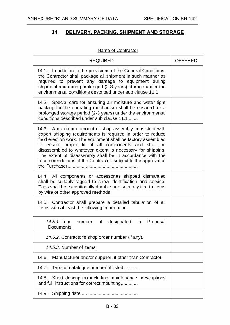
14. DELIVERY, PACKING, SHIPMENT AND STORAGE
Name of Contractor
REQUIRED OFFERED
14.1. In addition to the provisions of the General Conditions, the Contractor shall package all shipment in such manner as required to prevent any damage to equipment during shipment and during prolonged (2-3 years) storage under the environmental conditions described under sub clause 11.1
14.2. Special care for ensuring air moisture and water tight packing for the operating mechanism shall be ensured for a prolonged storage period (2-3 years) under the environmental conditions described under sub clause 11.1 .......
14.3. A maximum amount of shop assembly consistent with export shipping requirements is required in order to reduce field erection work. The equipment shall be factory assembled to ensure proper fit of all components and shall be disassembled to whatever extent is necessary for shipping. The extent of disassembly shall be in accordance with the recommendations of the Contractor, subject to the approval of the Purchaser ......................................................
14.4. All components or accessories shipped dismantled shall be suitably tagged to show identification and service. Tags shall be exceptionally durable and securely tied to items by wire or other approved methods
14.5. Contractor shall prepare a detailed tabulation of all items with at least the following information:
14.5.1. Item number, if designated in Proposal Documents,
14.5.2. Contractor's shop order number (if any),
14.5.3. Number of items,
14.6. Manufacturer and/or supplier, if other than Contractor,
14.7. Type or catalogue number, if listed, ..........
14.8. Short description including maintenance prescriptions and full instructions for correct mounting, ............
14.9. Shipping date, ...........................................

ANNEXURE “B” AND SUMMARY OF DATA SPECIFICATION SR-142
B - 33
14. DELIVERY, PACKING, SHIPMENT AND STORAGE
Name of Contractor
REQUIRED OFFERED
14.10. Shipping details. .......................................
14.11. The Contractor will be required to undertake to arrange on behalf of the Purchaser and in consultation with and at the expense of the Purchaser for the shipment in due time of the Automatic Resonance Controller to be supplied hereunder, on a vessel suitably equipped for loading the said equipment at the port of origin, for carrying the same and for unloading same at port of destination in Israel, and the Contractor shall further be required to undertake to have the Automatic Resonance Controller properly stowed on the said vessel, at Contractor's expense ..........................................
14.12. Total shipping weight (first stage):
14.12.1. Automatic Resonance Controller weight (Kg)
14.12.2. Current Injection Unit weight (Kg)
14.13. Total shipping volume (first stage):
14.13.1. Automatic Resonance Controller shipping volume (m3)
14.13.2. Current Injection Unit, shipping volume (m3)

ANNEXURE “B” AND SUMMARY OF DATA SPECIFICATION SR-142
B - 34
15. COMMISSIONING
Name of Contractor
REQUIRED OFFERED
15.1. The Contractor shall be responsible for all equipment covered under his contract ..................................
15.2. The Contractor shall prepare and submit three months prior to the start of commissioning, a Commissioning Program for approval by Purchaser ...................................
15.3. The Commissioning Program shall include indications for:
15.3.1. Commissioning inspection to detect faults which have occurred during transportation, storing or during assembly at its final location ........................................................
15.3.2. Preparation for use and procedures to describe the activities required to prepare systems for testing and operation.
15.3.3. Checking of rated data, connection, loading, etc. of the new equipment and necessary interface with the existing equipment supplied by others ..............................
15.3.4. Checking of indicating meters, relays, control and communications equipment and similar functions associated with the existing equipment .................................
15.3.5. Testing as detailed in tests on site program, including the following:
15.3.5.1. The test objective,
15.3.5.2. Test intent,
15.3.5.3. Required performance data,
15.3.5.4. Prerequisites,
15.3.5.5. Sequence of activities,
15.3.5.6. Acceptance criteria,
15.3.6. Putting the equipment into service ............
15.3.7. Final check ................................................
15.3.8. The critical limits of each criteria for which the equipment should be drawn out from service ........................

ANNEXURE “B” AND SUMMARY OF DATA SPECIFICATION SR-142
B - 35
15. COMMISSIONING
Name of Contractor
REQUIRED OFFERED
15.4. Changes and modifications to the Commissioning Program shall also be approved by Purchaser
15.5. Commissioning results shall be witnessed by the Purchaser and documented on forms to be agreed upon by the Contractor. The record shall include other such as omissions or unsatisfactory test results ....................................
15.6. The Contractor shall maintain an up-to-date record of all inspections and tests, which shall be handed over to the Purchaser at the completion of the site testing and commissioning .....................................................
15.7. The Contractor shall be responsible for making available to Purchaser a minimum of two complete sets of marked-up "as built" drawings before leaving the site. Contractor shall correct and reissue the original drawings as soon as possible
15.8. The Purchaser shall be responsible for the connection and disconnection of the new equipment to and from system, including first energization of new equipment, but with the advice and technical assistance of the Contractor (if required)
15.9. The Contractor shall be responsible for supplying commissioning personnel with a good knowledge in all relevant operations prior and for commissioning and will be requested to submit a list, giving name, experience and proposed duration on site (if required)...............................................
15.10. ................................................................... The commissioning personnel of Contractor shall be responsible for safety of personnel (where personnel ours or his own) involved in commissioning and shall take all possible precautions and be fully aware of the dangers involved in testing ..
15.11. In any case contractors personnel should also be insured against death and personal accident, and health while in Israel and be covered by employers liability insurance applicable in their country of origin

ANNEXURE “B” AND SUMMARY OF DATA SPECIFICATION SR-142
B - 36
15. COMMISSIONING
Name of Contractor
REQUIRED OFFERED
15.12. Major failure or damage to equipment will require either its return to the factory or assignment of a special crew to carry out repairs. Commissioning personnel shall repair minor failure as failures in metering, relaying control and communications equipment. All expensive in connection with damages and repairs as described above shall be paid by Contractor
ANNEXURE “B” AND SUMMARY OF DATA SPECIFICATION SR-142
B - 37
16. QUALITY CONTROL, RMS, MAINTENANCE AND INSPECTION
Name of Contractor
REQUIRED OFFERED
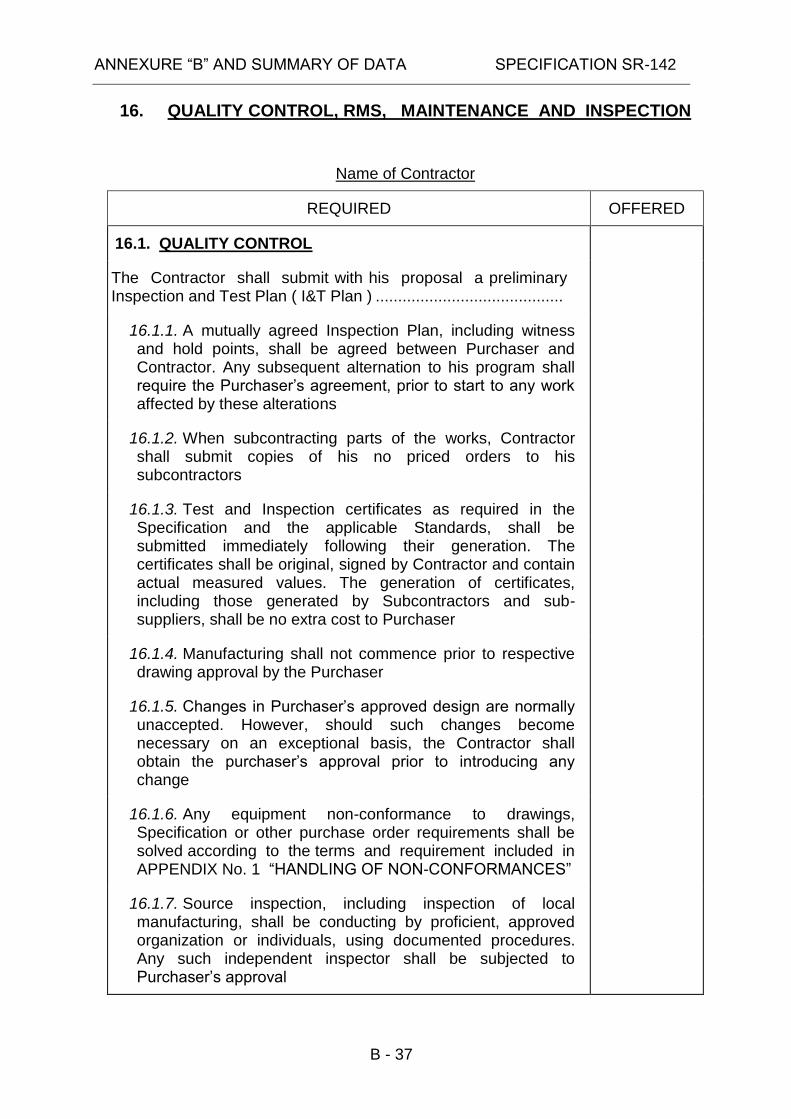
16.1. QUALITY CONTROL
The Contractor shall submit with his proposal a preliminary Inspection and Test Plan ( I&T Plan ) ..........................................
16.1.1. A mutually agreed Inspection Plan, including witness and hold points, shall be agreed between Purchaser and Contractor. Any subsequent alternation to his program shall require the Purchaser’s agreement, prior to start to any work affected by these alterations
16.1.2. When subcontracting parts of the works, Contractor shall submit copies of his no priced orders to his subcontractors
16.1.3. Test and Inspection certificates as required in the Specification and the applicable Standards, shall be submitted immediately following their generation. The certificates shall be original, signed by Contractor and contain actual measured values. The generation of certificates, including those generated by Subcontractors and sub-suppliers, shall be no extra cost to Purchaser
16.1.4. Manufacturing shall not commence prior to respective drawing approval by the Purchaser
16.1.5. Changes in Purchaser’s approved design are normally unaccepted. However, should such changes become necessary on an exceptional basis, the Contractor shall obtain the purchaser’s approval prior to introducing any change
16.1.6. Any equipment non-conformance to drawings, Specification or other purchase order requirements shall be solved according to the terms and requirement included in APPENDIX No. 1 “HANDLING OF NON-CONFORMANCES”
16.1.7. Source inspection, including inspection of local manufacturing, shall be conducting by proficient, approved organization or individuals, using documented procedures. Any such independent inspector shall be subjected to Purchaser’s approval

ANNEXURE “B” AND SUMMARY OF DATA SPECIFICATION SR-142
B - 38
16. QUALITY CONTROL, RMS, MAINTENANCE AND INSPECTION
Name of Contractor
REQUIRED OFFERED
16.1.8. All materials used in the manufacture of the equipment shall conform to the Specification, approved drawings and accepted Standards
16.2. RELIABILITY, MAINTAINABILITY AND SAFETY (RMS)
16.2.1. The proposed ARC/CIU shall comply with RMS requirements specified in APPENDIX No. 2
16.2.2. The Contractor shall submit the correct RMS data and information about the proposed ARC written in the RMS questionnaire
16.2.3. The proposed ARC/CIU will participate in Reliability Field Demonstration (RFD) specified in APPENDIX No. 2 and the Contractor will be responsible for consequences of RFD
16.2.4. The Contractor representative shall participate in Failure Review Board
16.3. MAINTENANCE AND INSPECTION
16.3.1. The proposed ARC/CIU shall be modular in order to facilitate the maintenance actions. Thus only the faulty module will be replaced.
16.3.2. Necessary maintenance work (please give details)
16.3.3. A complete set of tools for maintenance and repair work, shall be provided, together with relevant drawings or photos and full instructions for use in English
16.3.4. Time between successive periodical checking
16.3.5. Expected man hours required for periodical inspection and maintenance
16.3.6. Manufacturer shall ensure spare parts for Automatic Resonance Controller for a period of life duration

ANNEXURE “B” AND SUMMARY OF DATA SPECIFICATION SR-142
B - 39
17. TECHNICAL DOCUMENTS TO ACCOMPANY THE PROPOSAL
Name of Contractor
REQUIRED OFFERED
17.1. All data and descriptive material shall be in English
17.2. Description of the principles of operation of the offered equipment under various operating conditions
17.3. Description and drawing of the ARC including CIU
17.4. Operating instructions for ARC including CIU.
17.5. List of accessories with short description, technical data and catalogues
17.6. Information about design of structures
17.7. Example of routine test reports for offered equipment including test circuit, instruments used and description of method 2
17.8. Type test reports (authority, number and date) and special test for offered equipment including test circuit, instruments used and description method)
17.9. Final factory test report
17.10. Purchaser is interested in test values for offered equipment as supplied to various customers. Test reports for other types than offered can be considered only if guaranteed identical with those for offered types
17.11. Reliability and maintainability report
17.12. In addition Manufacturer is requested to fill in the enclosed APPENDIX No. 2 "Reliability, Maintainability, Safety (RMS) requirements" based on relevant information from users ( see also sub clause 16.2.2 Manufacturer shall describe the
system of relevant data collection from users
17.13. Shipping assembly drawings with overall size and weight.
2 In case tests have been performed also in other laboratory than Manufacturer's please
indicate.
ANNEXURE “B” AND SUMMARY OF DATA SPECIFICATION SR-142
B - 40
17. TECHNICAL DOCUMENTS TO ACCOMPANY THE PROPOSAL
Name of Contractor
REQUIRED OFFERED
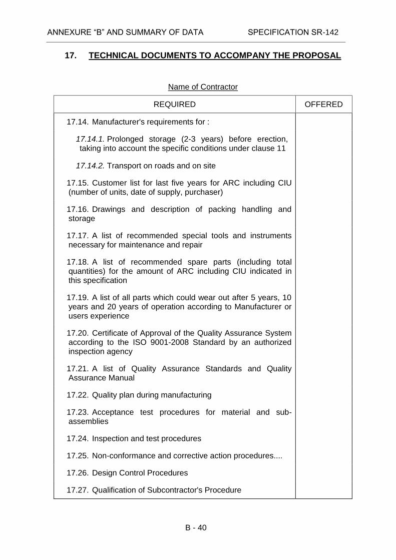
17.14. Manufacturer's requirements for :
17.14.1. Prolonged storage (2-3 years) before erection, taking into account the specific conditions under clause 11
17.14.2. Transport on roads and on site
17.15. Customer list for last five years for ARC including CIU (number of units, date of supply, purchaser)
17.16. Drawings and description of packing handling and storage
17.17. A list of recommended special tools and instruments necessary for maintenance and repair
17.18. A list of recommended spare parts (including total quantities) for the amount of ARC including CIU indicated in this specification
17.19. A list of all parts which could wear out after 5 years, 10 years and 20 years of operation according to Manufacturer or users experience
17.20. Certificate of Approval of the Quality Assurance System according to the ISO 9001-2008 Standard by an authorized inspection agency
17.21. A list of Quality Assurance Standards and Quality Assurance Manual
17.22. Quality plan during manufacturing
17.23. Acceptance test procedures for material and sub-assemblies
17.24. Inspection and test procedures
17.25. Non-conformance and corrective action procedures....
17.26. Design Control Procedures
17.27. Qualification of Subcontractor's Procedure

ANNEXURE “B” AND SUMMARY OF DATA SPECIFICATION SR-142
B - 41
17. TECHNICAL DOCUMENTS TO ACCOMPANY THE PROPOSAL
Name of Contractor
REQUIRED OFFERED
17.28. List of qualified suppliers of the most important parts and components (if applicable)
17.29. A list of optional items

ANNEXURE “B” AND SUMMARY OF DATA SPECIFICATION SR-142
B - 42
18. TECHNICAL DOCUMENTS AFTER NOTIFICATION OF AWARD
Name of Contractor
REQUIRED OFFERED
18.1. After notification of award, Contractor shall, within 30 days of the date of award, submit to the Purchaser for approval eight (8) sets of prints covering the following information:
18.1.1. Electrical schemes and diagrams for ARC including CIU and complete list of apparatus
18.1.2. Description and drawing of ground connector
18.1.3. Name plate drawings with all data fulfilled
18.1.4. Shipping assembly drawing with overall size and weight
18.1.5. Bill of materials
18.1.6. Instructions manuals, technical directives, drawings and any other relevant descriptive materials which shall contain all information required for the mounting, commissioning, operation, maintenance, periodic checking, periodic testing and repair of ARC including CIU.
18.2. Manufacturer is free to supply any additional information considered necessary for clarifying various aspects of operation, maintenance, etc.
18.3. Purchaser reserves himself the right to require all necessary additional data, descriptions, drawings, etc. that may contribute in completing information supplied by Manufacturer.
18.4. The drawings shall enable easy identification of all assemblies and parts of the equipment
18.5. If the prints are returned by the Purchaser and stamped "Approved Except as Noted", or relevant remarks are made in writing referring to the drawings, Contractor shall correct the drawings per the Purchaser's marking and shall resubmit required copies of the corrected drawings as stated above

ANNEXURE “B” AND SUMMARY OF DATA SPECIFICATION SR-142
B - 43
18. TECHNICAL DOCUMENTS AFTER NOTIFICATION OF AWARD
Name of Contractor
REQUIRED OFFERED
18.6. After approval of the above drawings and instruction books, but not less than 2 months before of delivery date, Contractor shall submit to the Purchaser for approval eight (8) sets of complete instruction books as may be required for erecting, operating, and maintaining the equipment. The instruction shall include recommended detailed procedures for commissioning and periodic testing and all pertinent test reports.
18.7. After approval of the above drawings and instruction books, but not less than 2 months before of delivery date, Contractor shall submit to the Purchaser Twelve (12) sets of prints of all drawings and one (1) reproducible print of each of those drawings
18.8. Instruction books shall include such drawing lists, performance test curves, lists of parts, etc., as may be required to give Purchaser complete information for the ordering of spare parts
18.9. All descriptive materials (lists, instruction books, etc.) should be numbered and dated for easy identification and reference purpose
18.10. All data and descriptive material in the above drawings and instruction books shall be in English. All dimensions shall be shown in metric units
18.11. All documents and drawings shall be provided with number of Purchaser order
18.12. Contractor shall provide two (2) copies of Quality Assurance Manual including a full description of Contractor’s Quality assurance program…………………….
18.13. Contractor shall furnish also the Quality Control documentation:
18.13.1. Inspection and Test Plan included in Contractor’s Quality Plan,
18.13.2. Quality Control Procedures,

ANNEXURE “B” AND SUMMARY OF DATA SPECIFICATION SR-142
B - 44
18. TECHNICAL DOCUMENTS AFTER NOTIFICATION OF AWARD
Name of Contractor
REQUIRED OFFERED
18.13.3. Electrical testing Procedures as per applicable Standards,
18.13.4. Non-conformance’s Procedures
18.14. Factory Acceptance test reports shall be submitted for approval 1 (one) month before delivery, the shipment cannot being released before Factory Acceptance tests approval
18.15. Commissioning program shall be submitted for approval 3 months before delivery
18.16. For information: Design Control Procedure (as applicable)

ANNEXURE “B” AND SUMMARY OF DATA SPECIFICATION SR-142
B - 45
19. COMMENTS BY MANUFACTURER ON ANNEXURE “B” AND SUMMARY OF DATA
Name of Contractor:

ANNEXURE “B” AND SUMMARY OF DATA SPECIFICATION SR-142
B - 46
20. EXCEPTIONS FROM REQUIREMENTS
Name of Contractor:
Manufacturer is requested to describe or indicate exceptions of the equipment and accessories from all requirements in this Specification.
In case no exceptions are mentioned it will be understood that Manufacturer’s offer entirely complies with all requirements in this Specification.

ANNEXURE “B” AND SUMMARY OF DATA SPECIFICATION SR-142
B - 47
21. CONFORMITY WITH PROPOSAL DOCUMENTS
Name of Contractor:
Contractor hereby certifies that he agrees to all provisions of the Proposal Documents unless exceptions are specifically and clearly listed in the proposal and identified as Exceptions.
Contractor’s printed terms and conditions are not considered specific exceptions. Any exceptions, which Contractor has taken, are listed on page B - 33.
Contractor hereby certifies that he agrees to all conditions of the cover letter of the Israel Electric Corporation Limited, which accompanied the Proposal Documents.
Signature of Contractor
Date of Proposal

ANNEXURE “B” AND SUMMARY OF DATA SPECIFICATION SR-142
APPENDIX No. 1

SR 142 APPENDIX NO. 1
___________________________________________________________________
The Israel Electric Corporation Ltd.
PROCEDURE
FOR
HANDLING OF NON-CONFORMANCES

SR 142 APPENDIX No. 1
___________________________________________________________________
2 of 3
It is the obligation of the Contactor to inform Israel Electric Corp. Ltd. (I.E.Co.) about
any deviation from the contract technical specifications, which occurs on any
action/item of the contract realization, such as design, raw materials, manufacturing
testing and inspection and so on. The deviations will be classified into the following
three (3) non conformance levels:
1. NON CONFORMANCE LEVELS
1.1. Non conformance (NC) of Level 1:
1.1.1. NC which do not affect the compliance to the contract technical
specifications and the contract value.
1.1.2. NC which leads to slight modification into the contract technical
specifications, but has certainly no effects on performance, neither on the
short term nor on the long term, as well as not on the contract value.
1.2. Non-conformance of Level 2:
1.2.1. NC which do not affect the contract value but leads to modification of
one or more the contract technical specifications, which has slight effects on
secondary performances.
1.2.2. Scrapping parts with influence on the delivery time.
1.3. Non-conformance of Level 3:
1.3.1. Any other NC which is not included in the previous levels (For
instance such a NC which can affect even uncertainly mandatory
requirement or contract value).
HANDLING OF NON CONFORMANCE
Contractor reporting duty according to each non conformance levels below:
1.4. Level 1: No duty of notification.
1.5. Level 2: Duty of notification.
Within one (1) week the Non Conformity Report will be
delivered to I.E.Co. Project Manager.
A Corrective Action (CA) Report is required, including the

SR 142 APPENDIX No. 1
___________________________________________________________________
3 of 3
influence on time schedule, or other relevant contract issue, if
any.
I.E.Co. has the right to send their remarks to the reports,
including discuss the NC level classification.
1.6. Level 3: Duty of notification and approval by IECo necessary.
1. The Contactor shall stop the manufacturing immediately.
2. The Contactor will deliver a NC Report to I.E.Co. Project
Manager within one (1) week.
3. When the disposition is to repair a detailed repair
procedure must be presented to I.E.Co for approval
immediately upon its issuing including a CA.
4. I.E.Co. will send its approval or rejection for the
disposition within one (1) week. Any and only
supplementary day will not be accounted as contactor
delay.
5. Only after I.E.Co.’s approval the Contractor can resume
manufacturing.
6. The NC equipment may be rejected in case of unsuitable
implementation of the repair procedure and/or the CA
taken.
7. Successful completion of the repair procedure and the
CA should be reported to I.E.Co.
ANNEXURE “B” AND SUMMARY OF DATA SPECIFICATION SR-142
APPENDIX No. 2

SR-142 APPENDIX No. 2
1 of 11
Reliability, Maintainability and Safety (RMS) Requirements
1.Requirements
I.E.Co. requires an Automatic Resonance Controller (ARC) for 24kV
overhead lines, in Israel, as described in Annexure “B” of Specification SR-
142. The following Reliability, Maintainability and Safety (RMS)
requirements shall characterize the new ARC device.
1.1.Reliability
The Contractor shall improve the design and manufacture the ARC for the
most possible higher reliability of the ARC, to achieve a very high Mean
Time Between Failures (MTBF), and Expected Operating Life (EOL).
1.1.1. The operational MTBF will be at least 50 Yrs.
Bidder Reaction:
1.1.2. The operational service life, EOL will be at least 20 Yrs.
Bidder Reaction:
1.2.Maintainability
1.2.1. Maintenance Policy
There will be 2 maintenance levels for the ARC:
1.2.1.1.Level “O” (Organizational): At I.E.Co.’s site, by I.E.Co.’s
technicians. At this level only removing and replacing of the faulty ARC
Important Notes: (1) For the RMS definitions please refer to paragraph 4 of this
Appendix (2) The Contractor is required to react on each and every one of the following paragraphs. (3) Please copy each paragraph of the following requirements into your reaction document and write your reaction right after each paragraph, using a different font. (4) In case of a lack of information/data, please write “No information/data available”.

SR-142 APPENDIX No. 2
2 of 11
and adjusting the new ARC will be allowed. The faulty ARC shall be
transferred for repairing to "D" level.
Bidder Reaction:
1.2.1.2.Level “D” (Depot): At Contractor’s representative Laboratory in
Israel. In this level, all maintenance actions shall be performed here.
Bidder Reaction:
1.2.2. Adjusting and Checking
Contractor’s trained I.E.Co.’s technicians will perform adjusting and
checking actions with I.E.Co.’s responsibility. I.E.Co. technicians will
perform these actions using contractor’s supplied documentation, and
I.E.Co.’s standard tools and test equipment. If special tools or special test
equipment will be required, the Contractor will supply them.
Bidder Reaction:
1.2.3. Preventive Maintenance and Periodical Checks
1.2.3.1.No Preventive Maintenance shall be required.
1.2.3.2.I.E.Co. will perform Periodical Checks every 2 Years in accordance
with contractor instructions
Bidder Reaction:
1.2.4. Corrective Maintenance
1.2.4.1.Level “O”
The Mean Time To Repair (MTTR) of the installed ARC at level “O”,
including checks and replacement will be less then 1/2 (half) an hour.
Bidder Reaction:
1.2.4.2.Turn Around Time
The Turn Around Time for any Maintenance Action will be less then 2
months and in accordance with contract requirement (See Paragraph
2.4).
Bidder Reaction:

SR-142 APPENDIX No. 2
3 of 11
1.3.Safety
The Contractor shall design and manufacture his ARC for I.E.Co. in such a
manner that it shall not endanger in any way any human being, neither
property, nor it causes any environmental damage. For achieving this
requirement, the Contractor is required to use the most advanced
engineering, and Safety Standards
Bidder Reaction:
2.Information/Data
2.1.Reliability
The Contractor shall declare the following Reliability parameters of the ARC:
2.1.1. The guaranteed value for MTBF under specified environmental
conditions is ____________Yrs.
2.1.2. The guaranteed value for Life Length (EOL) under specified
environmental conditions is ______ Yrs.
2.2.Maintainability
The Contractor shall declare the following Maintainability parameters of the
ARC:
2.2.1.Periodical Checks: No / Yes, every _______Yrs. The following is
performed:_____________________________________________________
______________________________________________________________
______________________________________________________________
( ) Possible at the field
( ) Manufacturer's Laboratory is mandatory
Special tools/equipment/instruments required at the field:________________
______________________________________________________________
______________________________________________________________
______________________________________________________________
Technician level ________________________________________________
______________________________________________________________
Mean Time to Check _____________________________________Hrs
2.2.2.Corrective Maintenance (Repair)
( ) Possible at the field

SR-142 APPENDIX No. 2
4 of 11
( ) Manufacturer's Laboratory is mandatory
Special tools/equipment/instruments required at the field ________________
______________________________________________________________
______________________________________________________________
______________________________________________________________
Technician level ________________________________________________
______________________________________________________________
______________________________________________________________
Mean Time To Repair ______________ Hrs
Maximum Time to Repair for Confidence level of 90% Hrs
Details________________________________________________________
______________________________________________________________
______________________________________________________________
2.3.Safety
Contractor shall indicate how he assures that his ARC cannot cause any
safety hazards at I.E.Co. He must clearly mention what safety measures,
and standards he used to Design the ARC. Contractor shall write them
below:
Safety measures and standards:____________________________________
______________________________________________________________
______________________________________________________________
______________________________________________________________
2.4.Spare Parts
Contractor shall present the method he is used to identify the needed spare
parts and their quantities for his offered ARCs, and submit his
recommendation list for these spare parts items
The following parameters should be considered for each spare part.
(1) Failure rate.
(2) Quantity in the ARC.
(3) Quantity of ARCs in this order
(4) Cost.

SR-142 APPENDIX No. 2
5 of 11
(5) Turn Around Time.
(6) Required Spare Parts availability.
Bidder Reaction:
2.5.Testability
Testability Analysis (FDP, FAP, etc), including the BIT.
Please check the relevant items
Testability by BIT: No / Yes, if Yes:
BIT type: ( ) Periodic ( ) Alarm ( ) initiated ( ) Power Up.
BIT Failure Detection Probability, FDP = detected/ total = ___
%.
BIT Failure isolation (FI) is down to:
( ) ARC level, ( ) Function level, ( ) module level, ( ) component
level.
BIT false Alarm Probability, FAP = ____ %
Failure alarm by: ( ) LCD ( ) LED ( ) Sound ( ) Other ,
Please specify________________________________________________
___________________________________________________________
___________________________________________________________
The above mentioned Testability parameters, FDP, and FAP were
determined by the following methods:_____________________________
____________________________________________________________
____________________________________________________________
2.6.Field Demonstration RMS data
In Addition to the RMS data mentioned above in Paragraph 2, Contractor
shall submit also the following historical information and data of his
proposed ARC. Please fill the information in the following table.

SR-142 APPENDIX No. 2
6 of 11
Table: Field Historical RMS Data for ____________________ Model
____________
Year 2009 2010 2011 2012 2013 2014
Total No. of supplied ARC's
Total No. of returns/ repairs due to defects/ faults/ failures/ errors
No. of Failures due to wrong design.
No. of Failures due to faulty production
No. of Failures due to bad use/handling
No. of Random failures
3. Demonstration/Tests
3.1.Purpose
The ARC that will be supplied by the Contractor to the I.E.Co. will be
participating in a “Reliability Field Demonstration” (RFD), in order to verify if
they stand the MTBF declared by the Contractor. I.E.Co. will accept the
ARC, only after successful completion of the RFD (when the test ended with
ACCEPT decision).
Bidder Reaction:
3.2.Failure Reporting Analysis and Corrective Action System
(FRACAS)
The I.E.Co. will implement an effective Failure Reporting Analysis and
Corrective Action System. In case of a failure, the I.E.Co. will register the
failure in a Logbook, with the following details:
- Date of occurrence.
- Failure description.
- Operating time to failure.

SR-142 APPENDIX No. 2
7 of 11
- Failure root cause.
- Failure end effect (consequence).
- Failure classification (relevant/Non-Relevant).
- Time to repair
- Corrective action
Bidder Reaction:
3.3.Principles
3.3.1.I.E.Co. will prepare the Test Plan for the ARC and implement it in
accordance with the "Sequential Test" procedures of Standard IEC-61124,
Reliability Testing – Compliance tests for constant failure rate and failure
intensity.
Bidder Reaction:
3.3.2.The parameter values for the test will be determined in a consultation
between Contractor, and I.E.Co. representatives.
Bidder Reaction:
3.3.3.No more than 2 systematic failures during the RFD are allowed. In case
of 3 systematic failures or more, the I.E.Co. has a privilege to stop the test
and to declare the ARC as "Rejected".
Bidder Reaction:
3.3.4.Following a "Systematic Failure" repair, the Contractor shall perform a
Corrective Action, as necessary, to all ARC units. The Corrective Action must
be done to Failure Review Board (FRB) satisfaction. After such a Corrective
Action, the FRB may decide, depends upon the failure severity, to zero the
test clock, and to restart the RFD from the beginning.
Bidder Reaction:
3.3.5.The Contractor does not have to invest any resources to the RFD,
except to participate in the FRB. However, the Contractor shall assume full
responsibility to the results and the consequences of the RFD. For the
purpose of the RFD, the Contractor should:

SR-142 APPENDIX No. 2
8 of 11
- Use suitable design to meet specifications.
- Select proper components, and parts.
- Use proper production processes.
- Apply rigorous Quality Control procedures.
Bidder Reaction:
3.3.6.Getting a “REJECT” result in the RFD will be considered as Contractor’s
noncompliance with the ARC specification.
Bidder Reaction:
3.4.Penalties
If the RFD is terminated in “Reject” decision, Contractor will expend his
Warranty Period for failures to a total period of five (5) years. In such a case
the Contractor will assume full responsibility for direct repair/replace costs
attributed to failures since the beginning of the Warranty Period, without any
cost to I.E.Co. whatsoever.
Bidder Reaction:
4.RMS Definitions
The following definitions are valid for all Reliability, Maintainability and Safety
(RMS) purposes in the specification for the Automatic Resonance Controller.
The RMS parameters are characteristics of the ARC design and production
only, when they are properly used and maintained.
(1) Failure
A Failure is any event where an ARC cease functioning or functions
outside of its specification limits, and requires a repair/replacement.
(2) Non Relevant Failure
A Non-Relevant failure for the purpose of the Failure Review Board (FRB)
is a failure that was classified by the FRB as such failure caused by:
- Bad handling, storage, transportation, or installation in I.E.Co.
- Test Equipment.
- External Force like: lightning, earthquake, abnormal storm, etc.
- Sabotage, or terror.

SR-142 APPENDIX No. 2
9 of 11
(3) Relevant Failure
A relevant failure for the purpose of the RFD is any failure that could
happen in real life, but could not be characterized as “non-relevant”.
(4) Failure Review Board
A Failure Review Board (FRB) is the only official, and authorized body
entitled to decide about failure matters, especially about failure
classification as “Relevant", or "Non Relevant”, to the RFD, The Contractor
will be represented in the FRB.
(5) Failure Rate
The failure rate, of an ARC is the number of failures per operating time
unit.
(6) MTBF
MTBF is the mean operating time between failures of ARC. MTBF = 1/.
(7) Reliability
Reliability is a design characteristic defining the ability of an ARC to
perform satisfactorily. Therefore: ARC reliability is the probability that an
ARC will perform without failures, for a pre-defined period of time, when
used under stated conditions (in I.E.Co.’s customer site). MTBF is a
reliability parameter.
(8) Life Length
The life length of an ARC is the time until the accumulated repair cost sum
up to the half of the price of a new one.
(9) Maintenance
Maintenance is any action taken by technical staff to:
- Restore a faulty item to its operable condition after a failure, or:
- Preserve the operable, or safety condition of a good item, or:
- Test the operable condition of an item.
(10) Maintenance Levels (echelons)
- Level “O” (Organizational): Performed on the ARC at I.E.Co. site, by
I.E.Co. technical staff.
- Level “D” (Depot): Performed on the ARC at Contractor’s representative
Laboratory in Israel.
(11) Corrective Maintenance

SR-142 APPENDIX No. 2
10 of 11
Corrective Maintenance (CM), or repair, is the maintenance action carried
out on an item of the ARC, after failure detection, and it intended to put the
item back into a state in which it can perform again its required function
satisfactorily (during the RFD).
(12) Preventive Maintenance
Preventive Maintenance (PM) is the maintenance actions carried out on a
good item, at predetermined intervals, or in accordance with prescribed
criteria, and intended to reduce the probability of a future failure, or
degradation of the functioning of the item.
(13) Maintenance Policy
Maintenance Policy is a description of the interrelationship between the
maintenance levels (echelons), the indenture levels of the ARC, the levels
of maintenance to be applied for the ARCs, and the required resources.
(14) MTTR
MTTR is the mean time required to perform a repair (including checks) or
replace of an ARC. The MTTR is given for the maintenance "O" level.
(15) Maintainability
Maintainability is a design characteristic defining the ability of an ARC
to be restored quickly to its operable condition after a failure.
Therefore, ARC maintainability is the probability that a failed ARC is
restored to its functioning condition, within specified period of time,
under stated condition, using stated procedures (defined by the
Contractor), and resources (defined by the I.E.Co.). MTTR is a
maintainability parameter.
(16) Built-In-Test (BIT)
A BIT is a test approach utilizing self-test hardware and software to test
all or part of the ARC functions.
(17) Testability
Testability is a design characteristic that allows the operational status
(operable, degraded, or failed) of an ARC to be accurately determined by a
BIT.
The testability is characterized by three parameters as follows:
- Failure Detection Probability, FDP - is the detectable failure rate divided
by the total failure rate (testability coverage), i.e.: detected/total).

SR-142 APPENDIX No. 2
11 of 11
- Failure Isolation, FI - is the level of the pinpointed identification of a failure
to a specific item within the ARC, i.e.: PCBs, module, parts.
- False Alarm Probability, FAP - is the probability of the BIT alarming of a
failure in an ARC, given that there was not any failure
(18) I.E.Co.
Israel Electric Corporation
(19) IEC
International Electrotechnical Commission

ANNEXURE “B” AND SUMMARY OF DATA SPECIFICATION SR-142
APPENDIX No. 3

THE ISRAEL ELECTRIC CORPORATION LTD. ORGANIZATION, QUALITY AND SAFETY DIVISION
QUALITY CONTROL UNIT APPENDICES FOR CONTRACTS / ORDERS TITLE Q - APP - 02
4 03/ 2011
PAGE 1 FROM 6
Spec. No. Rev.
Status Volume
QUALITY REQUIREMENTS
SUB TITLE
1. GENERAL
1.1 In addition to the provisions of the General Conditions – Annexure "A" and
without derogating from the generality there, the Quality Requirements as specified in this document constitute an integral part of the Contract between the Purchaser and the Contractor. Implementing these requirements shall not constitute any base/reason, for the Contractor to change the Contract schedule and/or price.
1.2 The Contractor shall make all the necessary arrangements and prepare all the
required and necessary means to enable IEC's Quality Control Unit Representative (see clause 2) to review, observe, audit, inspect, test and survey the Work - at any facilities where Work or any part thereof is performed, including those of Contractor and Sub- Contractors, without any additional cost to the Purchaser or any change in the Contract schedule.
1.3 The Contractor shall nominate, as part of the execution of the Contract a
quality engineer or a quality specialist to control and manage the quality requirements of the Contract. This person shall have the authority and responsibility with respect to all quality requirements of the Contract (including notifying the Purchaser about inspections, tests, etc.) and shall serve as Purchaser's liaison for quality matters.
1.4 The Contractor shall be responsible that all of the Contract’s quality
requirements are known, accepted and performed by its Sub- Contractors. Special attention should be given to Contractor's procurement control and its Sub- Contractor's design control, process and manufacturing control, purchasing control, nonconforming material/events control and inspection notification. Upon Purchaser's request Contractor shall submit un-priced copies of purchase orders pertaining to the Work/Contact.
PREPARED BY CHECKED BY APPROVED BY
B. Ben-Akiva Q.C. UNIT
QUALITY ENGINEERING
Y. Shubinsky Q.C. Dept. - North
MANAGER
R. Bandel Q.C. UNIT MANAGER
DATE AND SIGNATURE: 06/03/2011
DATE AND SIGNATURE: 06/03/2011
DATE AND SIGNATURE:
06/03/2011

THE ISRAEL ELECTRIC CORPORATION LTD. ORGANIZATION, QUALITY AND SAFETY DIVISION
QUALITY CONTROL UNIT APPENDICES FOR CONTRACTS / ORDERS TITLE Q - APP - 02
4 03/ 2011
PAGE 2 FROM 6
Spec. No. Rev.
Status Volume
QUALITY REQUIREMENTS
SUB TITLE
2. DEFINITIONS, CLASSIFICATIONS AND ABBREVIATIONS.
2.1. CORRECTIVE ACTION (CA) – As defined in ISO 9000:2005. 2.2. QUALITY PLAN (QP) - Plan, prepared by the Contractor especially for the
Contract, in accordance with ISO 10005 which covers all Contract stages.
2.3. INSPECTION AND TEST PLAN (ITP) – a plan, specifying all the inspections and tests for the Work throughout all Contract stages (from its initialing through design, in process inspection, type tests, product qualification, first article inspection, final inspection/s and test/s, packing, transportation and supply to the Purchaser, erection - including Site Acceptance Test and commissioning). ITP shall also specify Witness and Hold Points.
2.4. WITNESS POINT (WP) - a planned visit of the QCUR for purposes indicated
in clause 1.2 for specific point of the ITP or Quality Plan.
2.5. HOLD POINT (HP) – the same as WP but with the distinction that the Contractor is not permitted to proceed with its planned activities without having received Purchaser’s written approval.
2.6. NON CONFORMANCE (NC) - deviation from any specified Contract
requirement/s and/or from any quality characteristic of the Work. 2.7. NON CONFORMANCE REPORT (NCR) - a report, on Contractor’s numbered
serial form, describing the details of a Non conformance, from its detection through disposition and corrective action(s).
2.8. QUALITY CHARACTERISTIC – Any identifiable property of the Work (i.e.
physical ,chemical, functional, visual, technical, environmental, economical, statistical, legal etc.)
2.9. WORK - Scope of the Contract and the means to execute it. 2.10. QCUR - the Purchaser's Quality Control Unit Representative and/or any
authorized representative of it. 2.11. SPECIAL PROCESS - Irreversible manufacturing processes or processes
which require special or specific tools.

THE ISRAEL ELECTRIC CORPORATION LTD. ORGANIZATION, QUALITY AND SAFETY DIVISION
QUALITY CONTROL UNIT APPENDICES FOR CONTRACTS / ORDERS TITLE Q - APP - 02
4 03/ 2011
PAGE 3 FROM 6
Spec. No. Rev.
Status Volume
QUALITY REQUIREMENTS
SUB TITLE
3. QUALITY PLAN AND INSPECTION AND TEST PLAN
3.1 The Contractor shall prepare QP and ITP for all stages of the Contract. These plans shall be submitted to the Purchaser for approval within fourteen (14) days of initialing of the Contract by the parties. Contractor shall not amend, change or alter any part of the QP and/or ITP without the prior written approval of the Purchaser. Note: ITP shall conform to Exhibit 'A' attached hereto or any other form approved by the Purchaser.
3.2 Contractor shall not commence work prior to receiving Purchaser’s written
approval to the QP and ITP. 4. DOCUMENTATION
4.1 The Contractor shall submit to the Purchaser for review, along with the QP and ITP, its quality and manufacturing/operations procedures that pertain to the Work execution. The Purchaser has the right to receive explanations with respect thereto. Contractor shall provide Purchaser with all amendments and/or updates of documentation.
4.2 Special documents such as process procedures and inspection/test procedures written specifically for the Contract shall be submitted to the Purchaser, for review, comment and approval in accordance with Contract until the date agreed in there, but not less than twenty-one (21) days prior to its use.
4.3 The Contractor shall submit to the Purchaser, for review, comment and approval (as required by the Contract) all the process qualifications and the employees certifications for special processes which pertain to the Work and are relevant to the Contract execution.
4.4 Supplying Work which is not manufactured by the Contractor (under Contract terms) and which he has no control over the manufacturing process, shall not derogate from Contractors responsibility to supply the Purchaser with the documentation and quality records as indicated in Articles 4 and 7.

THE ISRAEL ELECTRIC CORPORATION LTD. ORGANIZATION, QUALITY AND SAFETY DIVISION
QUALITY CONTROL UNIT APPENDICES FOR CONTRACTS / ORDERS TITLE Q - APP - 02
4 03/ 2011
PAGE 4 FROM 6
Spec. No. Rev.
Status Volume
QUALITY REQUIREMENTS
SUB TITLE
5. INSPECTIONS AND TESTS
5.1 The Contractor shall have available all test and inspection equipment and/or any other means, required in Purchaser’s opinion, for the execution of Work and ITP.
5.2 If Contractor uses the services of a Sub - Contractor to carry out any
test/inspection required by the Work, only inspection companies certified to EN 45004 (level A or C) are acceptable.
5.2.1 Type test, Routine Test and Sample test shall be carried out according to
Contract requirements.
5.3 Any other qualification test (for mechanical equipment) shall be carried out in the presence of the QCUR, followed by all quality records. The serial manufacturing shall commence only after 1st Article/piece test have successfully carried out witnessed by the Purchaser's QCUR.
6. INSPECTION NOTIFICATION
6.1. The Contractor shall indicate each inspection/test and notify the Purchaser of it
in advance. An ITP schedule (on a GANT form) shall be prepared by the Contractor, within six (6) weeks after initialing of the Contract. Indications of inspection/test dates may in any event not be less than six (6) weeks in advance. Both inspection/test notification and ITP schedule shall be reported to the Purchaser's Project Management. In addition to the above ITP schedule, Contractor shall submit to Purchaser a final notice of planned tests/inspections not less than twenty-two (22) Israeli working days in advance.
6.2. Should Contractor fails to notify the Purchaser of a planned inspection/test, as
required, or in the event Contractor carries out a test/inspection without the required presence of the QCUR, Purchaser shall have the option of demanding that Contractor re-perform the test/inspection in the presence of QCUR at a time convenient to Purchaser and at no additional cost..
7. QUALITY RECORDS
7.1. The Quality Records stipulated in this clause shall be, either in Hebrew, in
dual/multi-language form with English, in English only, or if not available translated to English by Contractor.
7.2. Contractor shall submit to the Purchaser copy of the quality records documenting the inspections, tests or other quality operations of the Work, as indicated in the ITP, QP and the Contract. All quality records of skipped or missed WP and/or HP shall be submitted to Purchaser immediately after their generation.

THE ISRAEL ELECTRIC CORPORATION LTD. ORGANIZATION, QUALITY AND SAFETY DIVISION
QUALITY CONTROL UNIT APPENDICES FOR CONTRACTS / ORDERS TITLE Q - APP - 02
4 03/ 2011
PAGE 5 FROM 6
Spec. No. Rev.
Status Volume
QUALITY REQUIREMENTS
SUB TITLE
7.3. All Test and Inspection Certificates/ Reports of materials, operations and or
inspection/test, purchased or carried out for the Work and/or required by the applicable Standards, shall be submitted to the Purchaser immediately following their generation. These Certificates/Reports shall be original, in accordance with EN 10204:2004-3.1, containing actual measured values, signed and attested by Contractor. For any other document type, Contractor has to get Purchaser permission in advance.
7.4. Contractor shall make available to Purchaser upon its request, for review and comment, at Purchaser’s premises or other mutually agreed place (in Israel), the quality records of any - Type test, Routine test, Qualification test, First Article Inspection/Test, Process qualification, Special process and/or any other inspection/test/examination required by Purchaser, after initialing of the Contract, to evaluate the Work (at all stages) regardless of the QP and the ITP.
7.5. Submission of the documents and quality records, regarding the Equipment to
which the documents relate, to Purchaser, as specified in Articles 4 and 7, shall be a condition, precedent to shipment by Contractor and payment by Purchaser.
7.6. Quality records of inspections/tests and/or of process control and process evaluation pertaining to a Work such as shelf item, standard Equipment and/ or already completed Equipment to be supplied to Purchaser between 30 to 120 days after execution of the Contract, shall be immediately submitted to the Purchaser or at least 60 days prior to packing for shipment, respectively.
8. HANDLING OF NONCONFORMANCES AND CORRECTIVE
ACTIONS
8.1. It is Purchaser's policy to reject Work and/or Goods that do not conform to all contractual requirements, unless acceptance is in the best interests of Purchaser. Acceptance of nonconforming Work or Goods is the sole prerogative of Purchaser.
8.2. It is the Contractor’s obligation to report to Purchaser about any nonconforming item/event which pertain to the Work and are relevant to Contract execution.
8.3. If the Contractor fails to report about a non conformance on time, Purchaser may request Contractor to dismantle the nonconforming Work (to witness the NC) with no additional cost. The documentation and quality records concerning this NC shall be immediately submitted to the Purchaser.
8.4. Each NC should be followed by corrective action/s (CA). A NC which is not followed by CA shall be rejected.
8.5. Deviating from 8.4 can cause stoppage of the Work and its rejection till the proper CA is taken by the Contractor.

THE ISRAEL ELECTRIC CORPORATION LTD. ORGANIZATION, QUALITY AND SAFETY DIVISION
QUALITY CONTROL UNIT APPENDICES FOR CONTRACTS / ORDERS TITLE Q - APP - 02
4 03/ 2011
PAGE 6 FROM 6
Spec. No. Rev.
Status Volume
QUALITY REQUIREMENTS
SUB TITLE
EXHIBIT A
I&T Plan FORM
CONTRACTOR'S: NAME, I&T PLAN TITLE, THE PRODUCT INSPECTED/TESTED, and DOCUMENT IDENTITY &
APPROVAL.
PURCHASER'S: NAME AND PROJECT''S NAME AND LOCATION.
INSPECTED / TESTED BY
No.
THE INSPECTION OR TEST
APPLICABLEDCUMENTS
WP/HP OR
OTHER SUB-
CONT./ SUPP
CONTR- ACTOR
PURCH-
ASER
OTHER
THE REPORT /
CERTIFICATE AND
ITS REF. STD/ PROCEDURE
REMARKS
APPROVAL BY THE CONTRACTOR'S QUALITY ASSURANCE/CONTROL
NOMENCLATURE:

ANNEXURE “B” AND SUMMARY OF DATA SPECIFICATION SR-142
APPENDIX No. 4
NETWORK & SECURITY SAFEGUARDS REQUIREMENTS FOR CONTROL
PROTECTION AND DATA ACQUISITION SYSTEMS IN Transmission & substation
Division FACILITIES Page 1 of 13
Title:
NETWORK & SECURITY
SAFEGUARDS REQUIREMENTS FOR
CONTROL PROTECTION AND DATA
ACQUISITION SYSTEMS IN
Transmission & substation Division
FACILITIES
Document no.
20002-000000-2022
Rev.
01
Page
1
of
13
Doc. type
DOC
issued by Transmission &
substation Division
Language
English
Israel Electric Corporation
Rev.
Description kind of revision
00
First issue
Rev
Prepared
Date
1) Transmission & Substation Division
2) IT Division
3) Engineering Division
2022 December
00

NETWORK & SECURITY SAFEGUARDS REQUIREMENTS FOR CONTROL
PROTECTION AND DATA ACQUISITION SYSTEMS IN Transmission & substation
Division FACILITIES Page 2 of 13
Table of content
1 Scope…………………………………………………………………………… 3
2 Purpose of security safeguards…………………………………………… 3
3 General: IEC’s Specific Terms and Definitions……………………....... 4
4 Applicability…………………………………………………………………… 8
5 Requirements……………………………………..………………………….. 8
5.1 General Requirements
5.2 Security
5.2.1 Physical security
5.2.2 Logical security
5.3 Protection against viruses / worms / vandals / Trojan horses
5.4 Management of security safeguards
5.5 SCS-SCADA-DPMS systems interconnection
5.6 Security safeguards on application level
5.7 Means for disaster recovery
5.8 Remote Control / Maintenance / Support
5.9 Information exchange between IEC and Contractors / Suppliers
6 System Test…………………………………………………………………. 12
7 Abbreviations Glossary………………………………….……………….. 12

NETWORK & SECURITY SAFEGUARDS REQUIREMENTS FOR CONTROL
PROTECTION AND DATA ACQUISITION SYSTEMS IN Transmission & substation
Division FACILITIES Page 3 of 13
1. Scope
This document, intended as an annex to relevant specifications / contracts, deals with the issue of security safeguards for computerized control, protection and information systems, at a conceptual level. Data security is one of the most dynamic fields in the computerized systems environment and is in continuous change and adaptation to new threats. Therefore, this document does not aim to define specific solutions: the contractor / supplier shall propose adequate options, in keeping with global trends at the time of delivery of the supplied systems. Particular methods or technologies are mentioned below only for the sake of clarity.
2. Purposes of Security Safeguards
2.1 To ensure the safety of IEC personnel. 2.2 To prevent damage to IEC equipment. 2.3 To ensure the full operational capabilities of IEC computerized control, protection and information systems. 2.4 To maintain full system capabilities in the control and monitoring of IEC facilities. 2.5 To ensure the regular supply of high quality electricity to IEC’s clients. 2.6 To ensure the availability, integrity, authenticity and confidentiality of IEC data and systems.

NETWORK & SECURITY SAFEGUARDS REQUIREMENTS FOR CONTROL
PROTECTION AND DATA ACQUISITION SYSTEMS IN Transmission & substation
Division FACILITIES Page 4 of 13
3. General: IEC’s Specific Terms and Definitions
3.1 Communication Networks
Telecommunications network or computer network package is based on the
TCP/IP. A number of factors can be used simultaneously and securely.
Communications and security components are faster and support interfaces
with full branding L3 (in particular OSPF).
TCP data communication overlay will transport on OSI.
3.2 Communication Components
3.2.1 Network card (NIC - Network Interface Card): element that enables end
components quickly connect to the network and supports10/100/1000Mbps
network topology.
3.2.2 Components of communications and security: (Switch / FW) are used
to connect a link to the communication lines and elements in LAN & WAN
connections, including creating a secure communication logs and separation
3.3 Structure
3.3.1 Network topology: a model based on the Mesh.
3.3.2 OSI model (Open System Interconnection): a model based on a computer
network communication implementation.
3.3.3 TCP / IP model: the transport layer OSI model of computer networks
communication implementation.
3.3.4 Communication media: medium used to transport communications signals.
3.3.4.1 Couples intertwined: (Twisted pairs) local network communication
media, based on twisted pairs of copper cables intertwined.
3.3.4.2 RJ-45 connector's standard twisted pairs cables.
3.3.4.3 UTP (Unshielded Twisted Pairs) cable pairs woven without shielding
from external interference.
3.3.4.4 STP: (Shielded Twisted Pairs): each pair of wires included in flexible
metal shield for protection from electromagnetic interference.
3.3.4.5 Optical Fiber: communication media based on transparent materials
and principles of optics to transfer signals in the form of light.

NETWORK & SECURITY SAFEGUARDS REQUIREMENTS FOR CONTROL
PROTECTION AND DATA ACQUISITION SYSTEMS IN Transmission & substation
Division FACILITIES Page 5 of 13
LAN card installed network interface card end position be included on the
network, it is assigned a unique address for unique identification. Two
computers are connected with Ethernet communications; the authors have a
RJ45 cable to both ends of the cable. Each computer is connected directly
with the hub/switch, or FW that allows network computers to communicate.
3.4 Logical structure
3.4.1 Communication Protocol: A set of laws that create an agreed form of
communication.
3.4.2 Routing: A process that provides a means for planning a path for transferring
a packet of information between network endpoints.
3.4.3 IP Address (Internet Protocol Address): A unique address given to each
element on a computer network based on IP protocol.
3.4.4 LAN (Local Area Network): A computer network which spreads over a limited
geographical area (up to thousands of square meters).
3.4.5 VLAN (Virtual Local Area Network): LAN segment logically separated from
the rest of the network.
3.4.6 WAN (Wide Area Network): A computer network which connects the local
networks across a geographical space.
3.5 Standards and protocols.
3.5.1 Standards
3.5.1.1 802.1x - is a standard for access control for port-based networks. This
standard is used along with EAP methods, to enable supply access
control wired and wireless networks.
3.5.1.2 IEEE – (Institute of Electrical and Electronics Engineers) Institute of is
an organization involved in setting standards for computers and
communications).
3.5.1.3 ISO - An organization which establishes standards for products for
universal applications.

NETWORK & SECURITY SAFEGUARDS REQUIREMENTS FOR CONTROL
PROTECTION AND DATA ACQUISITION SYSTEMS IN Transmission & substation
Division FACILITIES Page 6 of 13
3.5.2 Protocols for specific uses
RFC number Description
2328 OSPF – Open Shortest Path First
1166 ARP – Address Resolution Protocol
792 ICMP – Internet Control Message Protocol
791, 917 IP – Internet Protocol
781 IP – IP Timestamp Option
2390 RARP – Reverse ARP
1035 DNS – Domain Name Server
1928 SOCKS
793, 3168 TCP – Transmission Control Protocol
768 UDP – User Datagram Protocol
2132, 3442 BOOTP – Bootstrap Protocol
1196 FUIP - Finger User Information Protocol
1276 Internet/X500 Translation
2254 LDAP - Lightweight Directory Access Protocol
1179 LPD/LPR – Printing
1094 NFS – Network File Services
1090 SMTP – Simple Mail Transfer Protocol
1081 SMTP/MIME, POP
1155, 1156, 1157 SNMP – Simple Network Management Protocol
1531 DHCP – Host Dynamic Configuration Protocol
22 SSH – Secure Shell
5246 VPN – Secure Sockets Layer
1079, 1372 TELNET - Telecommunication Network
1350 TFTP – Trivial FTP
1013 X Windows
959 FTP – File Transfer Protocol
468 FTP Data Compression
1945, 2616, 2817 HTTP – Hypertext Transfer Protocol
1057 RPC – Remote Procedure Call
738 Time Server
*** Designations will be reviewed and approved protocols by the State IEC

NETWORK & SECURITY SAFEGUARDS REQUIREMENTS FOR CONTROL
PROTECTION AND DATA ACQUISITION SYSTEMS IN Transmission & substation
Division FACILITIES Page 7 of 13
3.6 Command and Control
The central control of the switches, network and network required services will be
performed by a command and control system, which is required to provide:
3.6.1 Command and control system is required to provide a graphical interface to
control all components to-end network switches. (Switches, network and
network services required).
3.6.2 Required high integration of command and control system manufacturer's
switches.
3.6.3 All the switches, the network required network services, must be controlled
in real time.
3.6.4 Warnings and change status of the components will be reported and
displayed in the control system.
3.6.5 SNMP Agents must provide private MIB's include all network equipment
modules controlled by the switches, the functions and services running.
3.6.6 Control and Level 2 or higher.
3.6.7 Load reports, inventory, software versions are installed, special events,
errors, track configuration changes and more.
3.6.8 Command and control tools can run independently of the manufacturer in
addition to run through HPOV or ORION example.
3.6.9 Support for Policy based Networking, including an emphasis on service
quality management from end to end.
3.6.10 Equipment management capability through a Web browser.
3.6.11 Support for COPS Client.
3.6.12 Client support for LDAP.
3.6.13 Supported by SNMPv3.
3.6.14 RMON capability on all ports. SMON protocol can support or other similar
feature that allows to collect data for each Flow IP or application and export
them to separate.

NETWORK & SECURITY SAFEGUARDS REQUIREMENTS FOR CONTROL
PROTECTION AND DATA ACQUISITION SYSTEMS IN Transmission & substation
Division FACILITIES Page 8 of 13
4. Applicability
The security requirements shall apply to:
4.1 System architectures and designs.
4.2 Computer and microprocessor based systems / installations /devices
(hardware and software, both off-the-shelf and customized applications).
4.3 Communication networks (hardware and software, both off-the-shelf and
customized applications).
4.4 Real time or off-line systems.
4.5 Security equipment and capabilities.
4.6 Security implementation guidelines.
5. Requirements
5.1 General Requirements
Contractors / suppliers shall carefully address the following points:
5.1.1 Compliance with IEC’s general policy and rules of data security
defined throughout this document. Some aspects or nuances, specific to a particular project, will be decided during contract negotiations.
5.1.2 Both external (from outside IEC) and internal (from inside IEC) vulnerabilities.
5.1.3 Security measures on manufacturer’s production floor and during transportation.
5.1.4 Use of properly trained and skilled personnel (with respect to security aspects) both in production and support phase.
5.1.5 Clear identification of existent system vulnerabilities (still unsolved). 5.1.6 Detailed documentation regarding proposed security provisions
(including the above mentioned vulnerabilities). 5.1.7 The security provisions shall not prevent the system from
performing in all aspects according to the performance demanded by the technical section of the specification.
5.1.8 Prevention is preferred to post-intrusion detection. 5.1.9 When sub-contractors are involved, the main contractor still has the
full responsibility for overall compliance with security requirements. 5.1.10 Security provisions should be in accordance with generally
accepted security trends within computer community. 5.1.11 Use of state-of-the-art technologies. 5.1.12 Provide means for user-friendly periodical upgrades.

NETWORK & SECURITY SAFEGUARDS REQUIREMENTS FOR CONTROL
PROTECTION AND DATA ACQUISITION SYSTEMS IN Transmission & substation
Division FACILITIES Page 9 of 13
5.1.13 Security patches management procedure. 5.1.14 Software hardening (services should run only if needed, lock default
accounts). 5.1.15 Security equipment configuration. 5.1.16 Security and systems logs. 5.1.17 Network segregation (defining security zones and controlling traffic
between security zones) 5.1.18 Defining security aspects for Network protocols in use. 5.1.19 Authentication processes.(2 factor authentication) 5.1.20 Authorization management (Role-Based Access Control). 5.1.21 Redundancy. 5.1.22 System Trust Model.
5.1.23 User Trust Model. 5.1.24 Security levels. 5.1.25 Security Event Management. 5.1.26 Password Management.
5.2 Security
5.2.1 Physical security
In accordance with the project size and importance, the following points shall be considered and assessed:
5.2.1.1 Use of physical means of security (such as smart cards, tokens etc.) for user identification and authentication.
5.2.1.2 Seals and locks to avoid component theft (such as hard disk).
5.2.1.3 Use of external drives (CD, USB flash drives, memory cards etc.) with locked connector of access.
5.2.1.4 Use of fiber optic cables whenever appropriate (enhanced security protection).
5.2.1.5 If buildings or containers are supplied to house the purchased system, they will be equipped with security provisions approved by IEC (sturdy walls, steel doors, suitable locks, etc.)
5.2.1.6 Securing physical ports.
5.2.2 Logical security

NETWORK & SECURITY SAFEGUARDS REQUIREMENTS FOR CONTROL
PROTECTION AND DATA ACQUISITION SYSTEMS IN Transmission & substation
Division FACILITIES Page 10 of 13
Refers mainly to gateway between two or more Control / Monitoring Systems and other ones cover all the computer-based components:
5.2.2.1 Network protocols filtering. 5.2.2.2 (Network) address filtering. 5.2.2.3 Content filtering. 5.2.2.4 Intelligent filtering (rules). 5.2.2.5 Access Control Lists (ACL). 5.2.2.6 Concealment of the structure and nature of the data
systems or networks within the site. 5.2.2.7 Network traffic encryption. 5.2.2.8 Logs management, time stamping of Data Logs. 5.2.2.9 Security patches management and Firmware Updates. 5.2.2.10 OS and Software hardening. 5.2.2.11 Intrusion prevention / detection (IPS/IDS) 5.2.2.12 Security audits:
5.2.2.12.1 Logs 5.2.2.12.2 Monitoring of unusual events 5.2.2.12.3 Automate response (in case of intrusion)
5.2.2.13 Means for vulnerability analysis / assessment. 5.2.2.14 O.S. and programs hardening (definitions, options and
parameters shall be configured for the minimum, strictly necessary environment to successfully perform the required tasks).
5.2.2.15 Complex rules for passwords (shall complement the physical means for user identification and authentication).
5.2.2.16 DoS / DDoS prevention
5.3 Protection against viruses / worms / vandals / Trojan horses
5.3.1 Provision for compatible, efficient programs for online protection (on
all system computers, even when not explicitly exposed to such threats).
5.3.2 Detection, cleaning and logging of executed actions. 5.3.3 Methodology for secure and frequent updates.
5.4 Management of security safeguards
5.4.1 It is highly recommended that the provided security safeguards will
be managed through the same, integrated HMI, to the maximum possible extent.
5.4.2 Contractor / supplier shall provide friendly means (e.g. GUI) for: 5.4.2.1 configuration 5.4.2.2 monitoring 5.4.2.3 Testing

NETWORK & SECURITY SAFEGUARDS REQUIREMENTS FOR CONTROL
PROTECTION AND DATA ACQUISITION SYSTEMS IN Transmission & substation
Division FACILITIES Page 11 of 13
5.4.3 Updating / upgrading 5.4.4 Complex identification and authentication (at least two factors, such
as e-token and password) to access the control of security safeguards.
5.5 SCS-SCADA-DPMS systems interconnection
5.5.1 Security safeguards (such as dedicated electronic appliances,
protective gateways with at least ACL’s etc.) shall be used, when ever appropriate, at the interconnection point between systems.
5.5.2 Different suppliers of interconnected systems have to cooperate by providing the necessary information and taking part in inter-systems tests or start-ups.
5.5.3 Security serial SCADA communications. 5.5.4 Protection of routing protocols.
5.6 Security safeguards on application level
The control / monitoring application software has to provide protection against unintentional or hostile access to process data. While each manufacturer has its own approach (subject of decision during contract signing), there are common guidelines to be followed:
5.6.1 Implementation of secure programming rules, such as:
Input validation – whenever the input origination may constitute a threat.
Data base lock against "SQL injection".
Use of secure libraries throughout the code.
Well filtered error messages to prevent unveiling the code internal structure.
5.6.2 Minimal privilege (which still allows proper work environment). 5.6.3 Segregation of responsibilities (roles), e.g.: a) technicians, b)
operators, c) engineers, d) supervisors, e) system administrators, f) communication network administrators, g) security manager etc.
5.6.4 Different groups (classes) of security for writing (changing) process database points, e.g.: a) manual data update (lab data), b) alarm limit, c) alarm acknowledgement, d) command / set point, e) mode of operation, f) tuning, g) configuration etc.
5.6.5 Predefined scenarios for “which roles are permitted to do what tasks”.
5.7 Means for disaster recovery

NETWORK & SECURITY SAFEGUARDS REQUIREMENTS FOR CONTROL
PROTECTION AND DATA ACQUISITION SYSTEMS IN Transmission & substation
Division FACILITIES Page 12 of 13
If a disastrous shutdown happens, the system has to facilitate a rapid, easy and accurate recovery through:
5.7.1 Configuration data backup (automatically). 5.7.2 Key process data backup (automatically). 5.7.3 Mechanisms and predefined procedures for quick restoration
5.8 Remote Control / Maintenance / Support
Remote connections shall be avoided. When absolutely necessary, they shall follow the guidelines below:
5.8.1 From a technical point of view, the proposed connection –subject to
IEC's approval– shall be implemented securely, complying with IEC's corresponding procedures, and based on secure identification / authentication, authorization, encryption.
5.8.2 The connection shall be established for the shortest pre-specified period of time and only from pre-specified system(s) / location(s).
5.8.3 The connection shall be under the permanent supervision of authorized IEC personnel; IPS and / or IDS are recommended to monitor the connection.
5.8.4 Remote logins shall be logged in detail (who, when, for how long, from where, what actions have been performed etc.); providing adequate tool(s) for logs analysis shall be weighed.
5.9 Information exchange between IEC and Contractors / Suppliers
After contract award and through the startup period and site acceptance test there is an intense exchange of design data, documentation, software etc. between the Contractor / Sub-Contractors and IEC. Contractor's proposal shall detail all the hardware & software, methods and procedures for safe data exchange. Known, proven technologies, adapted to IEC’s infrastructure, are preferred. Guidelines are as follows:
5.9.1 Data encryption – decryption (optional). 5.9.2 Data source certification. 5.9.3 Data integrity certification. 5.9.4 Data receiving confirmation (at its destination). 5.9.5 Clear definition of IEC’s and other parties’ obligations for
implementing the safe information exchange.
6. System Test

NETWORK & SECURITY SAFEGUARDS REQUIREMENTS FOR CONTROL
PROTECTION AND DATA ACQUISITION SYSTEMS IN Transmission & substation
Division FACILITIES Page 13 of 13
6.1 A test proving the implementation of security safeguard requirements
should be run both on FAT and SAT.
6.2 Cyber vulnerability assessment on FAT and SAT.
6.3 Prior to test execution, a plan will be prepared by Contractor and then
discussed with and approved by Purchaser.
7. Abbreviations Glossary
7.1 ACL – Access Control List
7.2 SCS – Station Control System
7.3 DDoS – Distributed Denial of Service
7.4 DPMS – Data Processing and Monitoring System
7.5 DoS – Denial of Service
7.6 FAT – Factory Acceptance Test
7.7 GUI – Graphic User Interface
7.8 HMI – Human Machine Interface
7.9 IEC – Israel Electric Corporation Ltd.
7.10 IPS/IDS – Intrusion Prevention / Detection System
7.11 LAN – Local Area Network
7.12 EAP – External Authentication Protocol.
7.13 RFC – Request For Comments.

ANNEXURE “B” AND SUMMARY OF DATA SPECIFICATION SR-142
APPENDIX No. 5


ANNEXURE “B” AND SUMMARY OF DATA SPECIFICATION SR-142
APPENDIX No. 6

File: d-141707 updateed 15-7-2009.doc Page 1 of 3
.Israel Electric Corp. Ltd מ"חברת החשמל לישראל בע Generation & Transmission Group חטיבת ייצור והולכה Dpt Chemist Chief - Generation Division. מחלקת הכימאי הראשי-גף הייצור א Paints and coatings 04-8183362 - למלם דודא [email protected] Fax :8185706-04 8183158-04 - ליטני שי il.co.shay@iec
2009-217-141707 31.5.2009 (Update 15.7.09)
Specification for Coating Requirements of Load Transformers
The coating system shall supply protection against atmospheric corrosion for periods at least 15 year without need for maintenance.
Transformers shall be positioned in various environmental conditions. Some may be positioned in deserts and exposed to strong and direct sun radiation; other may be positioned in a polluted-marine environment classified as C5-M by ISO 12944-2.
Paints shall be applied in shop in the frame of SSPC – PA1. Field painting is not permitted.
Internal surfaces shall be painted only if such painting is a routine procedure of the transformer manufacturer, and can be proved to be successful by documents.
All external paints (and internal where applicable) shall be compatible with the transformer oil as supplied by the transformer manufacturer.
Internal paints shall not affect oil quality (as specified).
Cover painting shall be thicker and include tested antiskid solutions (Similar to MIL PRF24667B).
The transformer manufacturer is responsible for the paint quality.
Only coating systems for which the manufacturer has previous successful experience shall be suggested. In case of lack of experience in antiskid painting on the cover – the manufacturer may suggest an antiskid solution that was composed by the paint manufacturer.
All paint layers shall be by the same single paint manufacture.
The outer top-layer shade shall be RAL 7038. Internal shade (where applicable) shall be fair.
The final product shall be good looking, homogeneous, free from leaks and shall have a good adhesion to the transformer matrix.
The supplier shall suggest a coating system for the approval of Israel Electric Corp. Ltd. Such approval will include checking the suggested coating system to its purpose as well as compliance with all requirements of the current document.
The coating technical information shall be coordinated with the paints manufacturer and shall include at least:
• Materials
Paints manufacturer name and address, Generic classification of coating system, the full commercial paints name, technical datasheets of the paints and materials.
• Coating procedure description
Surface preparation procedures, description of application procedures, required surface roughness, special treatment of problematic areas (cover, thin edges, radiators, irregular thickness, stripe coats etc.

File: d-141707 updateed 15-7-2009.doc Page 2 of 3
• Quality control
List of Parameters to be measured and measuring standards (thickness, adhesion and their scattering are mandatory). Adhesion shall be according to " ISO 2409/2007 Paints and varnishes – Cross-cut test (methods A or B)"
• Previous experience:
The names and addresses of two (2) customers. Dates of application, project description.
• Maintenance repairing instructions: for damages during shipment of all painting systems
Appendix I: Examples for approved systems for some previous External manufacturers a. A Duplex system- Hot deep galvanized and painted (Information to be delivered by the
manufacturer):
• Galvanizing transformers is routine at the manufacturer's (indicate two customers)
• Galvanizing shall be according to "ASTM-A 153/2003 Std spec. for Zinc coating (Hot-Dip) on iron and steel" or by an international or regional accepted standard.
• The metal shall be suitable for galvanizing
• Surface preparation according to galvanizer's procedures
• Zinc thickness – 75 microns (minimum)
• Surface preparation for painting (without passivation).
• Paint system with the thickness of 120 micron (minimum), except cover having 220 microns (minimum) and antiskid requirements.
• Adhesion shall be of the upper grade according to standard and thickness.
b. Painted sprayed Zinc (Information to be delivered by the manufacturer):
• Submission of method and workers audition certificates
• Two customers' addresses with 5 years experience
• Surface preparation for Zinc spraying
• Zinc thickness of 150 microns (minimum), except cover having 220 microns of paint (minimum) and an antiskid requirements.
• Adhesion shall be of the upper grade according to standard and thickness.
c. A 3 layer system Zinc-rich/ Epoxy/ Polyurethane
• Zinc-rich base is the routine for the manufacturer (indicate two customers)
• Zinc-rich shall be stated according to ASTM-D 520
• Description of Surface preparation.
• Total Thickness of 250 micron (minimum, with base layer thickness of 70 microns) , except cover having 350 microns(minimum) and an antiskid requirements.
• Adhesion shall be of the upper grade according to standard and thickness
File: d-141707 updateed 15-7-2009.doc Page 3 of 3
d. A 3 layer system Epoxy/ Epoxy/ Polyurethane
• Epoxy/Epoxy/Polyurethane is the routine for the manufacturer (indicate two customers)
• Description of Surface preparation.
• Total Thickness of 350 micron (minimum, with base layer thickness of 70 microns), except cover having 450 microns (minimum) and an antiskid requirements.
• Adhesion shall be of the upper grade according to standard and thickness
Internal • Transformer declaration of this as a routine (indicate two customers).
• Paint manufacturer declaration for compliance with mineral transformer oil.
• Laboratory documentation for compliance with transformer oil
• Adhesion measuring method to be approved by IEC
Shay Litani Dr. Ehud Sutskover

ANNEXURE “B” AND SUMMARY OF DATA SPECIFICATION SR-142
APPENDIX No. 7

THE ISRAEL ELECRIC CORPORATION SPEC/PROCEDURE: CL-716/1600/99 GENERATION DIVISION ISSUE – 5 CHIEF CHEMIST DEPT. PAGE No. 1 of 7 (DATE: 09/03/07) Revised: June 2012
CL716-1600 rev 5 updated June 2012.doc Page 1 of 7
SPECIFICATION FOR PAINTING ON GALVANIZED SURFACES
BY WET or ELECTROSTATIC POWDER PAINTING
1. SCOPE
This specification covers the requirements for painting of steel surfaces hot dipped or
electrolytically galvanized.
Galvanized steel shall be protected by paint (duplex system) except for threaded items
such as nuts and bolts which will be chromated according to the instructions of the
laboratory of materials.
Painting on galvanized surfaces may be problematic and a test patch is
recommended in order to assure a proper adhesion of the primer on the prepared
surface.
In each project it's recommended to enable a patch test before the work.
The project manager will choose the painting system according to the environment
and to the kind of galvanized layer.
2. SURFACE PREPARATION
2.1 On hot dip Galvanized items
2.1.1 Solvent cleaning
Cleaning all surfaces from dirt, dust, oil, grease using a suitable
solvent to SSPC SP-1.
Approved “Chemitaas” products: “Ardox 6-551”, BC-70 or
similar products of other manufacturers.

THE ISRAEL ELECRIC CORPORATION SPEC/PROCEDURE: CL-716/1600/99 GENERATION DIVISION ISSUE – 5 CHIEF CHEMIST DEPT. PAGE No. 2 of 7 (DATE: 09/03/07) Revised: June 2012
CL716-1600 rev 5 updated June 2012.doc Page 2 of 7
2.1.2 Surface treatment
By one of the following methods:
A. Brush-off blast cleaning
According to SSPC-SP-7 specification.
Will be performed only by authorized workers.
Authorization shall be granted after ability to perform
roughening of the zinc coating and remove no more than 10
microns of the zinc layer. The zinc layer thickness shall be
examined before and after blasting.
B. Chemical treatment
Submerging the item in a phosphating bath type “ZINC-
PHOSPHATE” conforming to BS. 3189-1991standard.
2.2 On electrolytically galvanized items
2.2.1 Solvent cleaning
According to par. 2.1.1.
2.2.2 Surface treatment By one of the following methods:
A. Mechanical
The surface shall be roughened to a degree suitable for the
specified paint system.
Approved surface cleaning media are listed in par. 7.4.
B. Chemical treatment according to par. 2.1.2B.

THE ISRAEL ELECRIC CORPORATION SPEC/PROCEDURE: CL-716/1600/99 GENERATION DIVISION ISSUE – 5 CHIEF CHEMIST DEPT. PAGE No. 3 of 7 (DATE: 09/03/07) Revised: June 2012
CL716-1600 rev 5 updated June 2012.doc Page 3 of 7
3. PAINTING
ENVIRONMENT SUBSTRATE PAINTING SYSTEM THICKNESS MICRON
REMARKS
3.1 Internal location or external in a dry environment
3.1.1 Hot dip galvanizingzinc layer thickness over 80 micron
3.1.1.1 Liquid paints
Epoxy polyamide modified special for galvanizes surfaces / two component aliphatic polyurethane.
40
50
See par. 4.1 for approved manufactures and products see par. 6.1 and 6.2 remarks
Total 90
3.1.1.2 Electrostatic power painting with pure polyester powder
Total
60
60
See par. 4.2 for approved manufacturers and products. See par. 5 technical requirements.
3.1.2 Electrolyticaly galvanizing 20-40 micron zinc layer thickness
3.1.2.1 Liquid paints Epoxy polyamide modified special for galvanized surfaces
70
See par. 4.1 for approved manufactures and products
Two component aliphatic polyurethane.
50 See par. 6.1, 6.2 Remarks.
Total 120
` 3.1.2.2 Electrostatic powder painting with pure polyester powder
80
Total 80
See par. 4.2 for approved manufactures and products.
See par. 5 technical requirements.

THE ISRAEL ELECRIC CORPORATION SPEC/PROCEDURE: CL-716/1600/99 GENERATION DIVISION ISSUE – 5 CHIEF CHEMIST DEPT. PAGE No. 4 of 7 (DATE: 09/03/07) Revised: June 2012
CL716-1600 rev 5 updated June 2012.doc Page 4 of 7
ENVIRONMENT SUBSTRATE PAINTING SYSTEM THICKNESS MICRON
REMARKS
3.2 External location marine or industrial fume environment
3.2.1 Hot dip galvanizing zinc layer thickness over 80 micron
3.2.1.1 Liquid paint epoxy polyamide modified special for galvanized surfaces
70 See par. 4.1 for approved manufactures and products.
Two component Aliphatic Polyurethane
Total
50
120
See par. 6.1 and 6.2 Remarks
3.2.1.2 Electrostatic
powder painting Prime: Epoxy powder. Top: pure polyester powder Total
60 60
120
See par. 4.2 for approved manufacturer. See par. 5 technical requirements.
External location marine or industrial fume environment
3.2.2 Electrolitically galvanizing 20-40 micron zinc layer thickness
3.2.2.1 Epoxy polyamide modified special for galvanized surfaces. Two component aliphatic polyurethane Total
100
50
150
See par. 4 for approved manufacturers and products.
3.2.2.2 Electrostatic powder painting Prime: Epoxy powder. Top: pure polyester powder Total
60
60
120
See par. 4.2 for approved manufacturers. See par. 5 technical requirements.
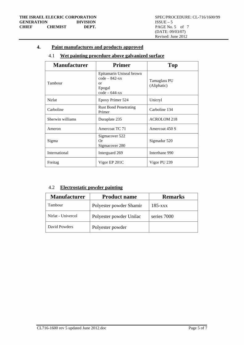
THE ISRAEL ELECRIC CORPORATION SPEC/PROCEDURE: CL-716/1600/99 GENERATION DIVISION ISSUE – 5 CHIEF CHEMIST DEPT. PAGE No. 5 of 7 (DATE: 09/03/07) Revised: June 2012
CL716-1600 rev 5 updated June 2012.doc Page 5 of 7
4. Paint manufactures and products approved
4.1 Wet painting procedure above galvanized surface
Top Primer Manufacturer
Tamaglass PU (Aliphatic)
Epitamarin Uniseal brown code – 842-xx or Epogal code – 644-xx
Tambour
UnicrylEpoxy Primer 524Nirlat
Carboline 134Rust Bond Penetrating PrimerCarboline
ACROLOM 218Duraplate 235Sherwin williams
Amercoat 450 SAmercoat TC 71 Ameron
Sigmadur 520Sigmacover 522 Or Sigmacover 280
Sigma
Interthane 990 Interguard 269 International
Vigor PU 239 Vigor EP 201C Freitag
4.2 Electrostatic powder painting
Remarks Product name Manufacturer
185-xxx Polyester powder Shamir Tambour
series 7000 Polyester powder Unilac Nirlat - Univercol
Polyester powder David Powders

THE ISRAEL ELECRIC CORPORATION SPEC/PROCEDURE: CL-716/1600/99 GENERATION DIVISION ISSUE – 5 CHIEF CHEMIST DEPT. PAGE No. 6 of 7 (DATE: 09/03/07) Revised: June 2012
CL716-1600 rev 5 updated June 2012.doc Page 6 of 7
5. Technical Requirement for electrostatic powder painting
Laboratory tests will be carried out on panels measuring 100 x 150 x 0.7 mm.
5.1 Thickness of Coating
At least 80 Microns. The test to be according to SSPC-PA1/1982.
5.2 Adhesion
Pull-off according to ASTM D 4541-85. Test dolly 20 mm. Using Acrylic
Adhesive (DP-805, Scotch-weld or equivalent). Minimum 1000 psi.
5.3 Hardness
Hardness of coating to scratching: 4000 gr. According to ISO R 1518.
5.4 Impact
According to ASTM D-2794: 25 Kg/cm. Will not be every cracking of
the coating, nor any detachment from the substrate.
5.5 Extensibility
ISO-1520-Erichsen Cupping: 6 mm without cracks or detachments.
5.6 Permeability
A coated panel will be partially submerged in pressure cooker containing
distilled water to a level of at least 25 mm. Cooking at least for two hours
after the appearance of steam.
After cooling of the cooker and the panel, the coating should be
examined: no bubbles should appear on the surface. (They are acceptable
only near the edges).
5.7 Resistance to Salt Spray Fog:
Three panels will be placed in al salt water chamber for 1000 hours after
being cross-cut in the center of the plate with an X, 50-70 mm long. After
drying for 24 hours at room temperature, adhesion to the cross-cut will be
examined.
Spread of rust along the lines and separation of the coating must not
exceed 2 mm. There must be no bubbles or rust spots on the surface
remote from the cut and the edges of the plate.

THE ISRAEL ELECRIC CORPORATION SPEC/PROCEDURE: CL-716/1600/99 GENERATION DIVISION ISSUE – 5 CHIEF CHEMIST DEPT. PAGE No. 7 of 7 (DATE: 09/03/07) Revised: June 2012
CL716-1600 rev 5 updated June 2012.doc Page 7 of 7
6. Quality assurance
Is based on the authorization of the process and manufacturer that shall be granted
after ability to supply panels that will conform the requirements specified in par.5.
During the fabrication only thickness off the coating will be checked. There are not
permited measurements under the specified thickness in par.5.1.
REMARKS
.1 Damaged hot dip galvanized surfaces must be repaired by applying at
least two coats of organic zinc rich coatings to give a minimum dry film
thickness of 60 micron.
Approved products:
“Z.R.C” – I.E.C - distributor carmel handasa catalog no. 3560067
“ ZINGA” - distributor m.b.l catalog no. 3560067.
ZINC-GLAD 5 - distributor Chemital. catalog no.3560067.
GLAVITE 90 E - distributor tambour catalog no.3560067
2. In the painting system will be involved only paints from the same
manufacturer
3. Every two successive coats must be colour contrasted.
4. I.E.C. will approve only paint products that permit over coating with the
paints specified in par 4.1.1. The result of adhesion test performed after over
coating according to Israeli Standard 785/27 will be at least level 1.
5. Surface profile producing media recommended: non-woven abrasive
wheels and discs such as: 3 M Scotch-Brite clean strip discs and wheels.
Coated abrasive discs (sending pads) as: Flap wheels such as: Grind 0
Flex Wheels from Merit Corporation
Needle guns consisting of a bundle of wire “needles” which can impact
the surface.
Prepared:
Y. Casapu Approved:
Dr. E. Sutskover
Revised by Shay Litani (June 2012)