specification for safety tfansformers (first revision)
TRANSCRIPT

IS : 1416 - 1972
Indian Standard SPECIFICATION FOR
SAFETY TFANSFORMERS
(First Revision)
( Fourth Reprint JUNE 1991 ) ( Incorporating Amendments No. 1, 2 and 3 )
t UDC 621’314’222’68
@ Copyright 1976
BUREAU OF INDIAN ST
MANAK BHAVAN, 9 BAHADUR SHAH NEW DELHI 110002
Gr 6
ANDARDS
ZAFAR MARG
F
1s : 1416- 1972
Indian Standard
SPECIFICATION FOR SAFETY TRANSFORMERS
( First Revision ) Electrical Appliances Sectional Committee, ETDC 43
Chairman
SHRI R. K. TANDAN
Members
SHRI S. N. BANWET
SHRI V. G. BAPAT
‘Representing
National Physical Laboratory ( CSIR ), New Delhi
Directorate General of Technical Development ( Co-ordination Section III ), New Delhi
Buildings & Communications Department, Government of Maharashtra
SHRI H. L. DESHPANDE ( Alta .ate) WQ CDR H. S. BHATIA Directorate of Technical Development & Produc-
SHRI H. C. PANDE (Alternate ) tion (Air ) ( Ministry of Defence ) , New Delhi
/CHIEF ENGINEER ( ELECTRICAL ) Central Public Works Department SURVEYOR OF WORKS
( ELECTRICAL I ) ( Alternate) SHRI S. S. CHITNIS
SHRI S. B. CHOILDIYA ( Alternafe) Elpro International Ltd, Poona
DEPUTY DIRECTOR (ELECTRICAL Railway Board ( Ministry of Railways ) ENQINEERINO )
DIRECTOR OF INDUSTRIES AND Department of Industries & Commerce, Govern- CONMERCE . ment of Tamil Nadu
SARI E N. NA~AYANASWAMY ( Alternate )
SHRI B. K. DOSHI Messrs Jashawantlal Kantilal, Bombay SHRI I. D. JAIN
SHRI R. S. JAIN ( Alternate ) Engineer-in-Chief’s Branch, Army Headquarters
SHRI RAJ KuM.~~ K~POOR Electrical Appliances Manufacturers Association, New Delhi
Sunr ARVIND V. KAS,\IXO~ SHRI D. D. KHOSLA
Tempo Industrial Corporation, Bombay Director of Industries, Government of Haryana,
Chandigarh SIIRI 0. P. Barry ( Alternate )
‘$1~1 S. Kunr~rt SHRI M. M. L. JIIA (Alternate)
National Radio & Electronics CO Ltd, Bombay
SHRI B. MAJ~~~DAR Small Scale Industries, Ministry of Industrial
SHRI J. V. BAP~RAJ ( Alternate) Development and Internal Trade, New Delhi
SHRIXATI B~ARGAVI MENON Lady Irwin College, New Delhi
( Continued on page 2 )
BUREAU OF INDIAN STANDARDS MANAK BHAVAN, 9 BAHADUR SHAH ZAFAR MARG
NEW DELHI 1 10002

IS I 1416 - 1972
( Continued from page 1 )
Mem berr Reprcsenfing
SHRI A. MITRA Directorate General of Supplies & Disposals SHRI V. S. KR~PALANI ( Alternate )
SHRI A. S. MOTAPRAM Refrigeration & Appliances Co Pvt Ltd, Poona SHRI VED KAPOOR ( Alternate )
SRRI S. K. MUKHERJEE National Test House, Calcutta SHRI B. MUKHOPADHYAY (Alternate 1
SHRI S. S. MUL~AONRAR SHRI S. K. MEHTA (Alfernafe)
SHRI S. NATARAJAN SIIRI R. IYAD~RAI ( Alfernafe )
SIXRI V. H. NAVKAL
Bajaj Electricals Ltd, Bombay
The Standard Electric Appliances, Tuticorin
The Bombay Electric Supply & Transport Under- taking, Bombay
SHRI R. V. S. RAO ( Alftrnafe ) SHRI JOGINDER SINGH PALL
SHRI HARDIT SINOH ( Affernafe ) SIXI~I V. S. RAO
SHRI SAT DEV ( Alfernafe ) SHRI L. N. SAKLANI
SHRI V. PAUL ( Alternate ) SI~RI Y. S. VENKATESWARAN,
Director ( Elec tech )
Ditz Electricals ( India ) Ltd, Delhi
Chief Inspectorate of Electronics, Ministry of Defcnce, Bangalore
Directorate of Industries, Delhi Administration, Delhi
Director General, IS1 ( fi-ofiio Meabtir )
Secretary
SIIRI HAXCHARAN SINGH Assistant Director ( Elec tech ), ISI
2
IS : 1416 - 1972
Indian Standard
SPECIFICATION FOR SAFETY TRANSFORMERS
( First Revision )
0. FOREWORD
0.1 This Indian Standard ( First Revision) was adopted by the Indian Standards Institution on 7 January 1972, after the draft finalized by the Electrical Appliances Sectiorral Committee had been approved by the Electrotechnical Division Council,
0.2 Safety transformers are used to supply distribution circuits, appliances or other equipment at extra low voltage. This standard covers the general, dety and performance requirements for safety transformers to ensure per- sonal safety against electric shock, safety against the effects of excessive temperature and fire, and reliable operation.
0.3 This standard was originally published in 1959. This revision has been brought out to make it up-to-date with respect to IS : 302-1973*. In this revision many requirements, especially the safety requirements and some others, such as protection against electric shock, temperature rise, electric strength, provision for carthing, crccpage and clearances, internal wiring, terminals and screws and rorrcctions have been more adequately included.
0.3.1 Another important cllange in this revision is the extending of the output voltage and power ratings from 25 V and 1 kVA to 32 V and 5 kVA respectively.
0.4 References to IS : 302- 1973. which is a necessary adjunct to this stand- ard, have been made. Should. however, any deviation exist between the requirements of IS : 302- 1973* and those of this standard, the provisions of the latter shall apply.
0.5 While preparing this standard, considerable assistance has been derived from CEE Pub 15-1961 Specification for safety isolating transformers, issued by International Commission on Rules for the Approval of Eltctrical Equipment.
~~~~~~~~ and saf.ty requirements for household and similar electrical appliances (fourth revision ).
3

IS : 1416 - 1972
0.6 For the purpose of deciding whether a particular requirement of thii standard is complied with, the final value, observed or calculated, express- ing the result of a test, shall be rounded off in accordance with IS : 2-1960*. The number of significant places retained in the rounded off value should be the same as that of the specified value in this standard.
1. SCOPE
1.1 This standard applies to stationary and portable, single-phase air-cooled safety transformers with extra-low output voltage, with a rated supply voltage not exceeding 250 V, a rated output not exceeding 5 kVA and a rated frequency of 50 Hz.
1.1.1 This standard applies to transformers, such as transformers for feed- ing extra-low voltage distribution circuits, transformers for heating blankets and for heating pads, transformers for portable tools, transformers for toys, bell transformers, hand lamp transformers, defrosting transformers and transformers for medical equipment.
1.1.2 Thii standard applies to transformers incorporated in appliances or other equipment, provided the conditions occurring in the appliance or equipment are taken into account. Examples of such transformers are: trans- formers in appliances for skin or hair treatment, transformers in solder- ing guns, transformers in medical or dental equipment and rectifier transformers.
1.2 It does not apply to oil-filled, sand-filled and similar transformers. In locations where special conditions prevail, as in ships, vehicles air field and the like, and in hazardous locations, for example, where explosions are liable to occ);ir, special constructions may be required.
1.3 This standard does not apply to transformers used in radio communi- cation equipment and similar purposes.
2. TERMINOLOGY
2.0 For the purpose of this standard, the definitions given in IS : 30241973t and the following shall apply.
NOTE - Where the terms voltage and current are used, they imply therms values, unless otherwise specified.
2.1 Safety Transformer - A transformer the input winding of’ which is electrically separated from the output windings, and which is designed to supply a distribution circuit, an appliance or other equipment at extra-low
*Rules for rounding off numerical values ( reuisen ). VGeneral and satety requirements for houwhold and similar electrical appliance (j&,th
rrtiton ) .
4

IS : 1416 - 19r12
voltage, that is, at a nominal voltage not exceeding 32 V between conductors.
2.2 Input Winding - The winding intended to be connected to the supply.
2.3 Output Winding - A winding to which the distribution circuit, appliance or other equipment for extra-low voltage is to be connected.
2.4 Rated Supply Voltage- The supply voltage assigned to the trans- former by the maker.
NOTE -If the input winding has tappings, the transformer is considered to have more than one rated supply voltage.
2.5 Rated Supply Voltage Range - The supply voltage range assigned to the transformer by the maker, expressed by its lower and upper limits.
NOTE -The rated supply voltage range refers to a single set of terminations; a transformer with a tapped input winding may have more than one rated supply voltage range.
2.6 Rated Frequency - The frequency assigned to the transformer by the maker.
2.7 Rated Output Current -The output current at rated supply voltage, and rated frequency and assigned to the transformer by the maker.
2.8 Rated Output Voltage - The output voltage at rated supply voltage, rated frequency and rattd output current at unity power factor, assigned to the transformer by the maker.
2.9 Rated Output - The product of the rated output voltage and the rated output current. If the transformer has more than one output winding or a tapped output winding, the rated output denotes the sum of the products of rated output voltage and rated output current for such circuits as may be loaded simultaneously.
2.10 No-Load Input -The input of the transformer when connected to rated supply voltage at rated frequency, with no-load on the output winding.
2.11 Short-Circuit Voltage -The voltage to be applied to input winding, when the windings are at room temperature, to produce in the short-circuited output winding a current equal to the rated output current.
NOTE - The short-circuit voltage is usually expressed as a percentage of the rated supply voltage.
2.12 Short-Circuit Proof Transformer - A transformer in which the temperature-rise does not exceed the specified limits when the transformer is overloaded or short-circuited.
2.13 Non-Inherently Short-Circuit Proof Transformer - A short- circuit proof transformer which incorporates a protective device, such as a
5

IS: 1416 - 1972
fuse, an overload release or a thermal cut-out, which opens the input circuit or the output circuit when the transformer is overloaded or short-circuited.
2.14 Inherently Short-Circuit Proof Transformer - A short-circuit proof transformer without any device for automatically opening the input circuit or the output circuit when the transformer is overloaded or short- circuited.
2.15 Non-Short-Circuit Proof Transformer - A transformer which is intended to be protected against, excessive temperature-rise by means of a protective device incorporated in the supply.
2.16 Hand Lamp Transformers supplying one or more hand lamps.
-A safety isolating transformer for
3. RATING AND CLASSIFICATION
3.1 Rated Voltage and Output
3.1.1 The rated output voltage shall not exceed 32 V. Preferred values for the rated output voltage are 6, 12, 24 and 32 V.
3.1.2 Preferred values for the rated output of single-phase transformers shall be chosen from the values given under 3.2 of IS : 302- 1973+ with the modifications that the rated output shall be expressed in kVA.
3.1.2.1 The rated output for transformers for toys shall not exceed 200 VA. For hand lamp transformers the rated output shall be not less than 25 VA, for rated output voltage not exceeding 12 V, and 60 VA, for other rated output voltages. For bell transformers the preferred values for rated output currents are 0’5, 1, 1’5 and 2 A.
3.2 Classification
3.2.1 The transformers shall be classified according to exposure of live parts as follows:
a) Unenclosed transformers, and b) Enclosed transformers. NOTE -For unenclosed transformers, the protection against electric shock is given
by the cwctusure of the appliance or other equipment in which the transformer is mounted.
4. DESIGN, CONSTRUCTION AND MATERIAL
4.1 In ad&lion ,to the following, relevant provisions of 5, 6 and 7 of IS : 302-1967* shall apply. The insulating materials, like enamel, varnish and leatheroid, and other materials like steel stamping shall conform to the relevant Indian Standards, wherever they exist. -
*General and safety requirements for household and similar electrical appliances (fourth wision ).
6

IS : 1416- 1972
d-1.1 PortabIe transformers having a rated output not exceeding 630 VA shall be of Class II ( double insulated ). shall be of Class II ( double insulated ).
In addition all transformers for toys
4.1.2 Class II (double insulated) transformers with accessible metal parts shall be provided with an insulating barrier in the form of an internal enclosure or the like, surrounding all parts of the input circuit, so that there is no possibility of bridging supplementary insulation or reinforced insulation. Such barriers shall be securely fixed in such a way that they cannot be removed without being seriously damaged or without making the transformer unfit for further use.
NOTE 1 - An adequate internal lining of insulating material or an adequ? L’ Internal’ insulating coating on metal enclosures, is deemed to be an insulating barrier. Lining tnetal enclosures with a ooating of lacquer, or with other material in the form of a coating which may be easily removed by scraping, is not deemed to be adequate.
NOTE 2 -A sleeve on an insulated conductor is not dccmcd to be adequate insu- lating barrier for the purpose of this requirement. The rcquirzment is met if the barrier is so fixed that it can only be removed by breaking or cutting.
4.1.3 If the input and output terminals are lscated on the same side of the transformer, they shall be separated by a barrier of insulating material which is integral with the transformer and, in addition the distance between ar,y terminal of the input circuit and every terminal of the output circuit, measured through the barrier, shall not be less than:
25 xnm for Portable transformers, and
50 mm for stationary transformers.
4.1.4 Portable drip-proof and splash-proof transformers having a rated output not exceeding 2’5 kVA shall be totally enclosed when fitted with wires in the manner prescribed by the manufacturer except that there shall be an effective drain hole at least 5 mm in diameter.
Watertight transformers shall be totally enclosed when fitted with wires in the manner prescribed by the manufacturer.
4.1.5 Bell transformers, hand lamp transformers and transformers for toys shall be enclosed transformers and portable hand lamp transformers shall be splash-proof. 5. COMPONENTS 5.1 In addition, to the requirements specified under 5.2 to 5.7 provisions of 5 of IS : 302- 1913* shall apply.
5.2 Socket-outlets in the output circuit shall not accept plugs complying with IS : 1293-1967t, neither shall it be possible to engage plugs accepted by socket-outlets in the output circuit, with socket-outlets complying with IS : 1293-1967t.
*General and safety requirements for household and similar electrical appliances (fourrh revision ).
jSpecification for three-pin plugs and socket-outlets (firsf reoision ).

IS t 1416 - 1972
5.3 Thermostats and thermal cut-outs shall comply with the requirements specified under 17 of IS : 302-1973 *. under 5.3.1 to 5.3.4 shall apply.
In addition, the requirements specified
5.301 Self-resetting thermal cut-outs and self-resetting overload releases shall not be used.
5.3.1.1 In case of toy transformers this requirement only applies to transformers with a short-circuit cument exceeding 20 A.
5.302 Thermal cut-outs incorporating low melting point alloys shall not be used for overload protection, unless frequent operation is not to be expected and the device is not easily accessible to the user, even after removal of the enclosure of the transformer.
NOTE - Transformers for heating-blankets and for heating-pads are examples where frequent operation of the protective device is not to be expected.
5.3.3 For toy transformers, self-resetting thermal cut-outs and self- resetting overload releases ( where provided ) shall operate reliably in extended use.
5.3.4 Non-self-resetting thermal cut-outs and non-self-resetting overload releases shall be trip-free and it shall be possible to reset them without removing covers.
5.4 Controllers, if any, shall be in the output circuit and shall operate reliably.
5.5 Protective dev.ices shall ndt operate with normal starting load,
5.6 Bare conductors shall be so fixed that the distance from one another and from the enclosure is adequately maintained.
5.7 Iqernal wiring shall not work loose when external wires are connected to the input or output terminals.
6. CHANGE OF VOLTAGE SETTING
6.1 Stationary transformers with more than one rated supply voltage shall be so constructed that the voltage setting cannot be changed without the aid of a tool.
Portable transformers shall have only one rated supply voltage.
NOTE 1 -Provisionally, portable transformers may have two rated supply voltages,
if the voltage setting can only be changed with the aid of a special purpose tool.
NOTE 2 -The requirement for stationary transformers is met if a tool has to be used to remove a cover before the voltage setting can be changed.
*General and safety requirements for household and similar electrical appliances ( fourfh revision ) .
8

IS t 1416 i 1972
Norm 3 - For the numose of this reauirement. a nortable transformer nrovided with a device for adjus&g' the input connections to suit supply voltage over a range of not more than 10 percent of the value corresponding with the midpoint of that range, is not constdered to be a transformer with more than ona rated supply voltage.
7. OUTPUT VOLTAGE UNDER LOAD
7.1 When the transformer is connected to rated supply voltage, at rated frequency, and loaded at rated output and unity power factory, the output voltage shall not differ from the rated value by more than:
10
10
15
10
percent for the output voltage of inherently short-circuit proof transformers with one rated output voltage,
percent for the highest output voltage of inherently short-circuit proof transformers with more than one rated output voltage,
percent for the other output voltages of inherently short-circuit proof transformers with more than one rated output voltage,
percent for the output voltages of transformers for toys, and
5 percent for the output voltages of other transformers. NOTE 1 - For transformers with more than one rated supply voltage, the require-
ment is applicable for each of the rated supply voltages.
NOTE 2 -For transformers with one or more rated supply voltage ranges, the requirement is applicable for the values of the rated supply voltage to which the other ratings refer ( see 12.2 ).
NOTE 3 - For transformrrs with tapped or multiple output windings which are not marked ( ste 12.3 ), the requirement applies only to the highest voltage setting of the control device.
8. NO-LOAD OUTPUT VOLTAGE
8.1 The no-load’ output voltage shall not exceed 32 V.
9. NO-LOAD CONDITIONS AND SHORT-CIRCUIT VOLTAGE
9.1 The no-load input current shall not exceed 33 percent of the value obtained by dividing the rated output in voltamperes, or 50, whichever is greater, by the rated supply voltage.
For bell transformers, the no-load input current shall not exceed 33 percent of the input current calculated from the rated output current, the rated output voltage and the rated supply voltage.
9.2 The no-load loss shall not exceed 3 W or 10 percent of the rated outpu: in voltampers, whichever is greater.
9.3 If there is a marking for short-circuit voltage, the short-circuit voltage measured shall not deviate by more than 20 percent from the value calculated from this marking.
9

tS:1416-1972
10. SHORT-CIRCUIT AND OVERLOAD PROTECTION
lo.,1 Transformers shall withstand short-circuits and overloads which may occur in normal use.
10.2 Portable transformers shall be short-circuit proof transformers, either inherently or non-inherently.
10.3 Unless there is a sound technical reason for the contrary, the protec- tive device of non-inherently short-circuit proof transformers shall be in the input circuit,
10.4 Transformers for toys shall be short-circuit proof transformers, either inherently or non-inherently, and shall withstand overloads which may occur in normal use; they shall not&corporate fuses.
10.5 If the short-circuit current exceeds 20 A, an overload release shall be incorporated in the input circuit,
10.6 Bell transformers shall be inherently short-circuit proof transformers and shall withstand overloads which may occur in normal use.
11. SAFETY AND PERFORMANCE REQUIREMENTS
11.1 Prptection Against Electric Shock -The provisions of 8 of IS : 302- 1973. shall apply in addition to those given under 11.1.1 to 11.1.5.
11.1.1 There shall be no connection between the output winding and the body or the earthing terminal, if any.
11.1.2 The input and output windings shall be seperated by an insu- lating barrier, and the construction shall be such that there is no possibility of any cohnection between these v+ndings, either directly or in&xcfly, through other metal parts,
11.1.2.1 In.particular, precautions shall be taken to prevent:
4 b) 4
4
4
displacement of input or output windings, or the turns thereof; displacement of internal wiring or wires for external connections; undue displacement of parts of windings, or of internal king,
in the event of rupture or loosening of connections; contact between accessible metal parts of Class I (functionally insulated ) transformers and conduits or metal sheaths of external wiring of the output circuit; contact between accessible metal parts of Class II ( double insu- lated) transformers and conduits or metal sheaths of supply wiring; and
*General and safety requirements fnr household and similar electrical appliances (fourth r&ion ) .
10

IS : 1416 - lM2
f) wires, screws, washers and the like from bridging any part of the insulation between the input circuit and the output circuits, including the windings, should they loosen or become free.
11.1.2.2 Neither the input winding nor the output windings shall be random wound.
NOTE 1 -Examples of constructions which comply with the requirements for windings of 11.1.2 are as follows:
a) Windings on separate spools of adequate insulating material, rigidly fixed with respect to each other and to the core of the transformer;
b) Windings on a single spool with a partition wall, both of adequate insulating material, provided that spool and partition wall are pressed or moulded in one piece, or that pushed-on partition walls have an intermediate sheath or covering over the joint between the spool and the partition wall; and
c) Concentric windings on cheekless formers, provided that:
1) each layer of the winding is interleaved with adequate insulating material projecting beyond the end turns of each layer.
2) a separate sheet of adequate insulating material of adequate thickness is provided between the input winding and the output windings, and
3) the windings are impregnated with a hard baking material which fully penetrates the interstices and effectively seals off the end turns.
NOTB 2 -It is not to be expected that two independent fixings will become loose at the same time.
11.103 Capacitors shall not be connected between:
a) input winding and output windings, b) input winding and core, and c) input winding and accessible metal parts.
11.1.4 In case of transformers for toys, it shall not be possible to gain access to live parts of the input circuit, or to metal parts separated from live parts by functional insulation only, even after the removal of covers, etc, which can be removed with the aid of common tools, such as pliers or screw-drivers.
llA5 In case of bell transformers, protection against a cidental J
contact with windings and live parts of the input circuit shall e ensured while connecting conductors to the output terminals,
11.2 Temperature Rise apply..
- *he provisions of 10 of IS : 302- 1973; shall /
113 Mechanical Strengtlcl- shall apply.
The provisions of 15.1 of IS : 302-1973.
11.4 Moisture Resimtance apply.
- The provisions of 13 of IS : 302- 1973. shall
*General and safety requirements for household and similar electrical appliances ‘(farrh retiion ) .
11
?
t.
IS:1416-1972
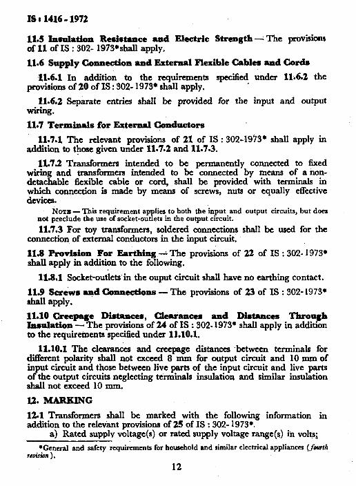
11.5 Insulation Resistance and Ektric Strength- The provisions of 11 of IS : 302- 1973+ shall apply.
11.6 Supply Connection andExternal Flexible Cables andCords
,11.6.1 In addition to the requirements specified under lli6.2 the provisions of 20 of IS : 302- 1973’ shall apply,
11.6.2 Separate entries shall be provided for the input and output WiliIlg.
11.7 Terminals for External Conductors
11.7.1 The relevant provisions of 21 of IS : 302-1973’ shall apply in addition to those given under 11.7.2 and 11.703.
11.7.2 Transformers intended to be permanently connected to fixed wiring and transformers intended to be connected by means of a non- detachable flexible cable or cord, shall be provided with terminals in which connection is made by means of screws, nuts or equally effective devices.
NOTE - This requirement applies to both the input and output circuits, but does not pr.eclude the use of socket-outlets in the output circuit.
11.7.3 For toy transformers, soldered connections shall be used for the connection of external conductors in the input circuit.
11.8 Provision For Earthing 2 The provisions of 22 of IS : 302- 1973’ shall apply in addition to the following,
11.8.1 Socket-outletsin the ouput circuit shall have no earthing contact.
113 Saows andConmctions - The provisions of 23 of IS : 302- 1973+ shall apply.
ll.;la~page Diaeeea, ClIearanees and Diatanees Jhro_vh - The provmons of 24 of IS : 302.1973. shall apply m addmon
to the requirements specified under 11.10.1.
11.10.1 The clearances and creepage distances .between terminals for diierent polarity shall not exceed 8 mm for output circuit and 10 mm of input circuit and those between live parts of the input circuit and live parts of the output circuits neglecting terminals insulation and similar insulation shall not exceed 10 mm.
12. MARKING
12.1 Transformers shall be marked with the following information in addition to the relevant provisions of 25 of IS : 302- 1973..
a) Rated supplv voltage(s) or rated supply voltage range(s) in volts;
*General and safety rcquircments for household and similar electrical appliances (fourlll f&.rion ) .
12
_.-
‘h (.
*
. ..“..

b) c> 4
4 f)
g>
h)
IS I 1416 - l!m
Rated output voltage(s) in volts;
Rated output in voltamperes or kilovoltamperes;
Bell transformers shall be marked with output current instead of output VA;
Rated frequency or frequencies in hertz;
Short-circuit voltage, expressed as a percentage of the rated supfly voltage, for stationary transformers with a rated output exceedmg 100 VA only;
Symbol for enclosed safety transformers or symbol for unenclosed safety transformers; whichever is applicable; and
Transformers for toys, bell transformers and hand lamp transform& shall be marked with the symbols specifying for these transformen instead’df the symbols for enclosed safety isolating transformem.
NOTE - If the transformer has more than one output winding, the short-circuit voltage to be marked is &lowest value for the various windings.
l2.1.1 The transformers may also be marked with the IS1 Certification Mark.
NOTE - The use oithe IS1 Certification Mark is governed by the proviaionr of the Indian Standards Institution ( Certification Mark8 ) Act and the Rule8 and Regulationa made thereunder. The IS1 Mark on products covered by an Indian Standard conveys the assurance that they have been produced to comply with the re uirements of that rtandard under a well-defined system of impection, testing and qua lty control which 1. h devised and stipervised by IS1 and operated by the producer. IS1 marked products are also continuously checked by ISI for conformity to that standard a# a further safeguard. Detaila of conditions under which a licence for the use of the IS1 Certifiu- tion Mark may be granted to manufacturers or processors, may be obtained from the Indian Standards Institution.
12.2 TransforIliers designed for a rated supply voltage range shall be so marked that it is clear to which value of the rated supply voltage the other markings depending on the rated supply voltages refer.
123 Transformers with tapped or multiple output windings shall be marked with the ‘rated output voltage for each tapping or winding, unless the transformer is intended for special purposes involving frequent changes in output voltage, and the rated output for each tapping or winding, unless it is the same for every tapping or winding.
12.3.1 The arrangement of the connections necessary to obtain the various output voltages shall be clearly indicated on the transfbrmer.
NOTE - Examples of transformers intended for special purposes involving frequent changes in output voltage are transformers for toys with variable speed and transfor- mers with variable output for special lighting purposes.
12.4 Non-short-circuit proof transformers shall, in addition, ‘be marked with the symbol for fuses, followed by the rated current in amperes of the appropriate protecting fuse-link.
13

JS : 1416 - 1972
12.4.1 Inherently short-circuit proof transformers shall, in addition, be marked with the symbol for inherently short-circuit proof trasnformers.
12.4.2 Non-inherently short-circuit proof transformers with incorporated fuses shall, in addition, be marked with the rated current in amperes of the protecting fuse-link, followed by the symbol for time-lag fuses, if applicable,
12.4.3 Non-inherently short-circuit proof transformers with incorporated interchangeable protective devices other than fuses shall, in addition, be marked with:
a) maker’s’ model or type reference of the device, and b) rating of the device.
12.5 Transformers provided with terminals for more than one rated supply voltage shall have either of the following additional markings:
a) A diagram showing circles to represent the terminals, the appro- priate circles being joined by lines,. with the corresponding values of the rated supply voltages placed adjacent to these lines; and
b) The values of the rated supply voltages, which shall be positioned near to the corresponding terminals, so that it is clear how the transformer should be connected to the supply.
12.6 When symbols are used, they shall be as follows:
a) Enclosed safety transformer
b) Unenclosed safety transformer
c) Fuse
dk Time-lag fuse
e) Inherently short-circuit proof transformer
14

f ) Transformers for toys
g) Bell transformers
h) Hand lamp ,transformer
12.7 The symbol for unenclosed safety transformers shall not be visible when the transformer is mounted in an appliance or other equipment.
12.8’Marking related to terminals shall be so pIaced that it is clearly discernible after removal of the cover, if necessary; it shall be such that there can be no confusion between input terminals and output terminals.
Marking related to interchangeable protective devices, shall be so placed on or adjacent to the bases of these devices, that it is clearly discernible after removal of the cover and the protective device, if necessary.
13. TE&TS
13.1 The tests specified in Table 1 shall constitute type tests &d those in Table 2 acceptance tests and those in Table 3 routine tests.
13.1.1 Type tests shall be carried out on the number of samples speci- fied below of safety transformers of the same model, type and ratings:
a) If it is not necessary to do the tests of 13.9.3, the number of samples is:
2 if the rated output does not exceed 100 VA. 1 if the rated output exceeds 100 VA.
b) If the tests of 13.9.3 have to be made, three additional samples are required, with a further three should these tests have to be repeated.
13.1.1.1 Criteria of agproval - All samples shall successfully pass all the type tests except a.5 mentioned in 13.9.3 for proving conformity with the requirements of this standard. of the type tests, testing
If any of the samples should fail in any authority, at its discretion, may call for fresh
samples not exceeding twice the original number and subject them again to ali tests or test in which failure(s) occurred, permitted in the repeat test(s).
No single failure shall be
15
IS : 1416 - 1972
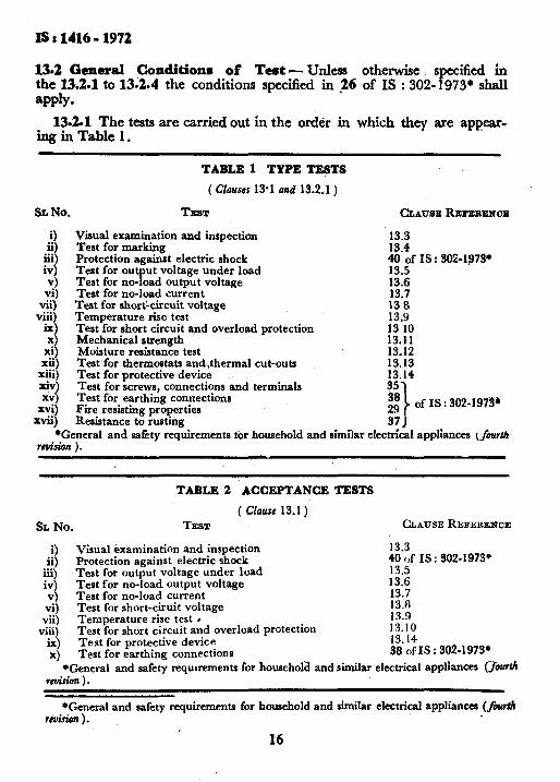
13.2 General Conditionm of Test - Unless otherwise specified in the 13.2.1 to 13.2.4 the conditions specifkd in 26 of IS : 302- 1973. shall
13.201 The tests are carried out in the o&r in which they are appear- inginTable 1.
SL No.
3 ii)
iii) iv) v)
TEST CLAUI~E~~E~EIWX
Visual examination and inspection 13.3 Test for marking 13.4 Protection against electric shock 40 of IS: $02~19791 Test for output voltage under load 13.5 Test for no-load output voltage 13.6
vi) Test for no-load current 13.7 vii) Test for shortlcircuit voltage 13 8
viii) Temperature rise test 13.9 ix) Test for short circuit and overload protection 13 10 x) .13.11
xi) Mechanical strength Moisture resistance test 13.12
xii) Test for thermostats and$hermal cut-outs 13.13 xiii) Test for protective device 13.14 xiv) Test for screws, connections and terminals xv)
Xvi) Test for earthing connections E Fire resisting properties
2q of IS : 302-19731
xvii) Resistance to rusting 3; 1 *General and safety requirements for household and similar electrical appliances &A/I
r#uis&Jn ) .
TABLE 1 TYPE TESTS
( CIousss 13.1 alui 13.2.1)
TABLE 2 ACCEPTANCE TESTS
( Cfause 13.1)
SL No. TEST CLAUSE REFERENCE
i) Visual examination and inspection 13.3 ii) Protection against electric shock 40 of IS : 302-1973.
iii) Test for output voltage under load 13.5 iv) Test for no-load. output voltage 13.6
v) Test for no-load current 13.7 vi) Test for short-ciruit voltage 13.8
vii) Temperature rise test l 13.9
viii) Test for short circuit and overload protection 13.10
ix) Test for protective device 13.14
x) Test for earthing connections 38 of IS : 302-1973’
*General and safety requirements for household and similar electrical appliances (&rti r&n 1.
*General and safety requirements for household and similar electrical appliances (f&a& r&.rio?J ).
16

IS: 1416-1972
TABLE 3 ROUTINE TESTS
( Clause 13.1)
SL No. TEST CLAUSEREFERENCE
9 Visual examination and inspection 13.3
ii) Protection against electric shock 40 of IS : 302-1973’
iii) Test for output voltage under load 13.5
iv) Test for no-load output voltage 13.6
v) Test for no-load current 13.7
vi) Test for short circuit voltage 13.8
vii) Test for earthing connections 38 of IS : 302-1973,
*General and safety requirements for household and similar electrical appliahces (four#~ revision ) .
13.2.2 For ac, test voltages shall be of substantially sine-wave form.
13.2.3 Transformers designed for more than one rated supply voltage, for a rated supply voltage range or for more than one rated frequency, are tested at the supply voltage or frequency that imposes the most severe conditions for the transformer in the test concerned.
13.2.4 If Class I ( functionally insulated ) transformers have parts with double insulation or reinforced insulation, such parts’ are also checked for compliance with the appropriate requirements specified for Class II ( double insulated ) transformers.
13.3 Visual Examination and Inspection-The safety transformer shall be visually examined and inspected for conformity with the relevent require- ments of 3.1, 4, 5, 6, IO, 11.1, 11.6 and 12.
13.4 Test for Marking - Compliance is checked by inspection and rubbing the marking by hand with a piece of cloth soaked with water and again with a piece of cloth soaked with petroleum spirit.
13.5 Test for Output Voltage Under Load - Compliance is checked by measuring the output voltage when steady conditions are established, the transformer being connected to rated supply voltage, at rated frequency, and loaded at rated output and umty power factor.
13.6 Test for No-Load Output Voltage - Compliance with the require- ments of 8.1 is checked by measuring the no-load output voltage, when the transformer, at room temperature, is connected to rated supply voltage, at rated frequency.
13.6.1 The measured no-load output voltage shall not exceed 32 V and the difference between the value measured and the output voltage measured during the test given in 13.5, expressed as a shall not exceed the value shown in Table 4,
percentage of the latter voltage,
17

IS : 1416 - 1972
TABLE 4 DIFFERENCE BETWEEN OUTPUT VOLTAGE AT NO-LOAD AND AT RATED OUTPUT
TYPE OF TRANSFORMER
Inherently short-circuit proof transformers:
Up to and including 63 VA
Over 63 to and including up 630 VA
Over 630 VA
Other transformers:
Up to and including 63 VA
Over 63 to and including up 630 VA
Over 630 VA
DIFFERENCE OF VOLTAGEM
percent
100
50
20
20
10
5
13.6.2 For hand lamp transformers, the measured no-load output voltage shall not exceed 32 V and the difference between the value measured and the output voltage measured during the test of 13.5 expressed as a percentage of the latter voltage, shall not exceed 7’5 percent.
NOTE 1 - For transformers with tapped or multiple output windings which are not marked ( see 12.3 ), the no-load output voltage is tncasurcd when the control device is at the highest voltage setting.
NOTE 2 - For transformers combined with a rcctilier, the output voltages are measured on both sides of the rectifier.
13.7 Test for No-Load . Current - Compl;ance with the requirements of 9.1 and 9.2 is checked by measuring the no-load loss, when the trans- former, at ‘room temperature, is connected to rated supply voltage, at rated frequency.
13.8 Test for Short-Circuit Voltage - Compliance with 9.3 is checked by measuring the short-circuit voltage, the transformer being at room temperature.
13.9 Temperatare Rise - Compliance with the requirements specified under 11.2.1 shall be checked by the test specified under 41 of IS : 302-1973*, unless otherwise modified by 13.9.1 to 13.9.3.
13.9.1 Unenclosed transformers are tested in a suitable enclosure. NOTE - Detriils with regard to the enclosure are under consideration.
13.9.2 The transformer is connected to rated supply voltage and loaded with rated output current at unity power factor; then the supply voltage is increased by 10 percent.
*General and safety requirements for household and similar electrical appliances (Jourfh reonion ) .
18

IS : 1416 - 1972
13.93 If there is doubt with regard to the classification of the winding insulation, the transformers are kept in a heating cabinet for 40 days ( 960 hours), except that they are removed for 1 hour and kept in an ambient temperature of 27 f 5°C on every third day.
The temperature of the air within the heating cabinet is maintained within 1°C of 18O”C, or of 80% plus the highest winding temperature rise determined during the temperature rise test, whichever is the higher.
The transformers are then subjected for 2 days ( 48 hours ) to moisture treatment in accordance with 43 of IS : 302-1973’ followed by an electric strength test as specified in 5.1 of IS : 302- 1973*, the test voltages being, however, reduced by 500 V and applied only between input and output windings and between these windings and the body.
Immediately afterwards, each transformer is fixed to a wooden board of approximately the same size as the perpendicular projection of the trans- former on to this board. The board is then released from a horizontal position, so that it falls through a distance of 50 mm on to a horizontal rigid wooden surface. Fifty such falls are made, at intervals of one second.
The transformers are then immediately subjected to ‘an electric strength test as specified in 42.3 of IS : 302-1973*, and are deemed not to comply if more than one sample fails.
If one sample fails, the tests of this clause are repeated on another set of three samples, all of which shall then comply with the repeated tests.
13.10 Test for Shortt;Circdt and Overload Protection
13.10.1 Compliance with the requirements specified in 10.1 is checked by the test of 13.102 for inherently short-circuit proof transformers, by the tests of 13.10.3-and 13.10.4 for non-inherently short-circuit proof transfor- mers and by the tests of 13.10.4 for other transformers.
Unenclosed transformers are tested in a suitable enclosure. NOTE 1 - For transformers with more than one output winding or a tapped output
winding, the results to be considerded are those showing the greatest temperature rise.
NOTE 2 - Details with regard to the enclosure are under consideration.
13.10.2 The output terminals of inherently short-circuit proof transfor- mers are short-circuited immediately after the temperature rise test, the position of the transformer being unchanged and the supply voltage being maintained at a value equal to 1’1 times rated supply voltage.
When steady conditions are established, temperature ‘rises are determined as described in 13.9; they shall not exceed the values shown in Table 5.
NOTE -For transformers for toys during the tests of 13.10.2 and 13.10.3, rectifiers, if any, in the output circuit are short-circuited.
*General and safety requirements for household and similar electrical appliances (&arUt revision ) .
19 ‘-

IS t 1416 - 1972
TABLE 3 LIMITS OF TEMPERATURE RISE
( Clauses 13.10.2, 13.10.3 and 13.10.4)
PARTS TEMPEBATU~E RISE OC
Windings insulated with:
Class A material 120
Class E material 145
Other material*
External enclosures 100
Rubber or polyvinyl chloride insulation 50
Supports of stationary transformers 70
*There is on limit specified for windings insulated with materials other.than those of Class A or Class E, but they shall withstand the tests of 13.9.3, the tempera- ture of the air within the heating cabinet being maintained within 1°C of 186”C, or of 80°C plus 0.6 times the highest winding temperature rise determined during the test of this clause, whichever is higher.
13.10.3 The output terminals of non-inherently short-circuit proof transformers are short-circuited immediately after the temperature rise test, the position of the transformer being unchanged.
The incoporated protective device shall operate before the temperature rises exceed the values shown in Table 5 for any value of the supply voltage between 0.9 and 1’ 1 times rated supply voltage.
In addition, transformers for toys with a short-circuit current exceeding 26 A are connected, in cold condition, to rated supply voltage and the output circuits are short-circuited.
The overload release shall operate within one second. NOTE -If the toy transformer has more than one output circuit, these are, if
necessary, short-circuited in turn.
13.10.4 Transformers other than inherently short-circuit proof trans- former, are operated under the conditions specified in 13.9, until steady conditions are established. The transformers are then loaded as specified below, the supply voltage being maintained at a value equal to 1’1 times rated supply voltage:
a) Non-short-circuit proof transformers are loaded for one hour so that the current in the input winding is equal to c times the value marked on the transformer as the rated current of the protecting fuse-link, where c has the value shown in Table 6.
b) The fuse-link of non-inherently short-circuit proof transformers is replaced by a link of negligible impedance, and the transformer

IS : lii6 - 1972
is kded for one hour so that the current in the fused circuit is equal to 2’1 times the rated current of the fuse-link.
NOTE -If the short-circuit current of the transformer is smaller than the current specified in items (a) and (b), the transformer is short-circuited until steady conditions are established.
c) Transformers incorporating thermal cut-outs are loaded so that the current attains the maximum possible value without causing the cut-out to operate, the test being continued until steady conditions are established.
d) Transformers incorporating overload releases are loaded to 95 percent of the tripping current of the release, until steady conditions are established.
For the purpose of this test, the tripping current is as follows:
1) The lowest current which will operate the release, for releases without time delay, and
2) The current which will operate the release with maximum delay, or after one hour, whichever is the shorter period, starting from room temperature for releases with time delay.
During the tests, the temperature rises shall not exceed the values shown in Table 5.
NOTE - The tests are made on each winding or section in turn the other windings or sections being loaded with their rated output current.
TABLE 6 VALUES OF c
VALUE MARKED AS RATED CURBENT OP PROTECTINQ FUSE-LINK
A
Up to and including 4
Over 4 up to and includmg 10
Over 10 up to and including 25
Over 25
C
2-l
I.9
1.75
1.6
13.11 Medanical Stren f
th - The stationar transformers shall be tested in accordance with 36.1 o 1s : 302-1973*. ?y he portable transformers shall be tested in accordance with 13.11.1.
13.11.1 Drop Test -The appliance shall be allowed to fall in % normal position of use, 50 times on a concrete floor, from a height of 5’0 cm;
*General and safety requinments for household and similar electrical applimca (fourth reaision ) .
21

IS:1416-1972
13.11.1.1 A typical test apparatus is shown in Fig.’ I.
AWLIAN C ‘E
50mm I:
FIG. 1 APPARATUS FOR DROP TEST
13.12 hfoistrve Resistance Test - The P
rovisions of 43 and 44 of IS : 302-1973+ shall apply, in addition to the allowing.
*General and safety requirements for household and similar electrical appliances (fourth reuision ) .
22

IS : 1416 - 1972
13.12.1 Insulation resistance between input and output winding shall be measured and it shall not be less than 5 megohm.
13.12.2 A high voltage test at 4 000 V shall be made between the live parts of input and output windings.
13.13 Tests for Thermostats and Thermal Cut-Outs
13.13.1 The transformer is connected to a voltage equal to 1’1 times rated supply voltage and the output terminals are short-circuited until the thermal cut-out or overload release operates.
After the transformer has cooled down to room temperature, the cut-out is reset, the fuse-link replaced or the release reset.
This cycle of operation is carried out ten’ times. During the test, no sustained arcing shall occur and there shall be no damage from other causes.
13.13.1.1 In case of toy transformers, for non-self-resetting thermal cut-outs and non-self-iesetting’ overload releases, the number of cycles of operations is increased to 1 000.
l3.,13.1.2 In case of toy transformers, the compliance with the require- ments of 5.3.3 is checked by short-circuiting the output terminals for 2 days ( 48 hours ), the transformer being connected to a voltage equal to 1’ 1 times rated supply voltage.
During the test, the device shall operate satisfactorily and no sustained -arcing shall occur.
13.13.1.3 Compliance with requirements of 5.3.4 is checked by short circuiting the output terminals, the transformer being connected to rated supply voltage.
It shall not be possible to maintain the thermal cut-out or the overload release in the ‘ on ’ position without removing any cover.
13.14 Test for Protective Device - Compliance with requirements of 6.2 is checked by the following test.
13.14.1 The transformer, with no-load, is connected to a voltage equal to 1.1 times rated supply voltage, non-short-circuit proof transformers being protected by A fuse with a rating in accordance with the marking of the transformer. The transformer is switched on and off 20 times, with an interval of one minute between each on and off operation,
13.14.2 The protective device for non-short-circuit proof transformers, namely, the fuse, shall not operate.
13.14.3 Unenclosed transformers are tested in a suitable enclosure. 13.14.4 The supply source shall be such that there is no appreciable drop
in voltage as a result of the inrusli current. NOTE - &tails with rt-gard to the enclosure are under consideration.
23

BUREAU OF INDIAN STANDARDS
Headquarters :
Manak Bhavan, 9 Bahadur Shah Zafar Marg, NEW DELHI 110002
Telephones : zzi yi 73: Telegrams : Manaksanstha (Common to all Offices,
Regional Offices:
Central : Manak Bhavan. 9, Bahadur Shah Zafar Marg,
NEW DELHI 110002
*Eastern : l/14 C.I.T. Scheme VII M. V.I.P. Road, Maniktola, CALCUTTA 700054
Northern : SC0 445-446, Sector 35-C, CHANDIGARH 160036
Southern : C.I.T. Campus, IV Cross Road, MADRAS 600113
twestern : Manakalaya, E9 MIDC, Marol, Andheri (East), BOMBAY 400093
Branch Offices :
‘Pushpak’, Nurmohamed Shaikh Marg, Khanpur, AHMADABAD 380001
SPeenya Industrial Area, 1 st Stage, Bangalore-Tumkur Road, BANGALORE 560058
Gangotri Complex, 5th Floor, Bhadbhada Road, T.T. Nagar, BHOPAL 462003
Plot No. 82/83, Lewis Road, BHUBANESHWAR 751002
Kalai Kathir Building, 6/48-A Avanasi Road, COIMBATORE 641037
Quality Marking Centre, N.H. IV, N.I.T., FARIDABAD 121001
Savitri Complex, 116 G.T. Road, GHAZIABAD 201001
5315 Ward No. 29, R.G. Barua Road, 5th By-lane, GUWAHATI 781003
5-8-56 C L. N. Gupta Marg, (Nampally Station Road), HYDERABAD 500001
R 14 Yudhister Marg, C Scheme, JAIPUR 302005
117/418 B Sariodaya Nagar, KANPUR 208005
Plot No. A-9, House No. 561/63, Sindhu Nag&, Kanpur Road, LUCKNDW 226005
Patliputra Industrial Estate, PATNA 800013
District Industries Centre Complex, Bagh-e-Ali Maidan, SRINAGAR 180011
T.C. No, 14/1421, University P.O., Palayam, THIRUVANANTHAPURAM 695034
Inspection Office (With Sale Point)
Pushpanjali, First Floor, 205-A, West High Court Road, Shankar Nagar Square, NAGPUR 440010
Institution of Engineers (India) Building, 1332 Shivaji Nagar, PUNE 411005
*Sales Oftice Calcutta is at 5 Chowringheo Approach, P.O. Prmcep Street, CALCUTTA
tSales Office is at Novelty Chambers, Grant Road, BOMBAY
*Sales Office is at Unity Building, Narasimharaja Square, BANGALORE
Telephone
331 01 31
331 13 75
37 86 62
53 38 43
235 02 16
632 92 95
2 63 48
39 49 55
55 40 21
5 36 27
2 67 05 -
8-71 19 96
3 3177
231083
6 34 76
21 68 76
5 55 07
6 23 05 -
6 21 04
52 51 71
5 24 35
27 68 00
89 65 28
22 39 71
Printed at Print-O- Bind, New Delhi. India